US9457158B2 - Air trap for intravenous pump - Google Patents
Air trap for intravenous pumpDownload PDFInfo
- Publication number
- US9457158B2 US9457158B2US13/640,519US201113640519AUS9457158B2US 9457158 B2US9457158 B2US 9457158B2US 201113640519 AUS201113640519 AUS 201113640519AUS 9457158 B2US9457158 B2US 9457158B2
- Authority
- US
- United States
- Prior art keywords
- fluid
- set interface
- air
- air chamber
- valve
- Prior art date
- Legal status (The legal status is an assumption and is not a legal conclusion. Google has not performed a legal analysis and makes no representation as to the accuracy of the status listed.)
- Expired - Fee Related
Links
- 238000001990intravenous administrationMethods0.000titleclaimsabstractdescription21
- 239000012530fluidSubstances0.000claimsabstractdescription128
- 238000013022ventingMethods0.000claimsabstractdescription56
- 238000011282treatmentMethods0.000claimsdescription21
- 230000001954sterilising effectEffects0.000claimsdescription15
- 238000004659sterilization and disinfectionMethods0.000claimsdescription15
- 230000037452primingEffects0.000claimsdescription13
- 238000005086pumpingMethods0.000claimsdescription10
- 230000009471actionEffects0.000claimsdescription9
- 230000008859changeEffects0.000claimsdescription4
- 238000000034methodMethods0.000description9
- 238000002512chemotherapyMethods0.000description8
- 238000001802infusionMethods0.000description8
- 239000012528membraneSubstances0.000description7
- 231100000331toxicToxicity0.000description6
- 230000002588toxic effectEffects0.000description6
- 239000007789gasSubstances0.000description5
- 238000011109contaminationMethods0.000description4
- 239000003814drugSubstances0.000description4
- 238000004519manufacturing processMethods0.000description4
- 229940079593drugDrugs0.000description3
- 239000000126substanceSubstances0.000description3
- 238000011144upstream manufacturingMethods0.000description3
- 238000009825accumulationMethods0.000description2
- 230000008901benefitEffects0.000description2
- 230000007246mechanismEffects0.000description2
- 238000012986modificationMethods0.000description2
- 230000004048modificationEffects0.000description2
- 230000008569processEffects0.000description2
- 230000005355Hall effectEffects0.000description1
- 229940044683chemotherapy drugDrugs0.000description1
- 238000010276constructionMethods0.000description1
- 238000005516engineering processMethods0.000description1
- 238000007667floatingMethods0.000description1
- 239000003517fumeSubstances0.000description1
- 239000003978infusion fluidSubstances0.000description1
- 230000009191jumpingEffects0.000description1
- 230000001473noxious effectEffects0.000description1
- 230000008520organizationEffects0.000description1
- 238000006467substitution reactionMethods0.000description1
- 238000012360testing methodMethods0.000description1
- 231100000925very toxicToxicity0.000description1
Images


Classifications
- A—HUMAN NECESSITIES
- A61—MEDICAL OR VETERINARY SCIENCE; HYGIENE
- A61M—DEVICES FOR INTRODUCING MEDIA INTO, OR ONTO, THE BODY; DEVICES FOR TRANSDUCING BODY MEDIA OR FOR TAKING MEDIA FROM THE BODY; DEVICES FOR PRODUCING OR ENDING SLEEP OR STUPOR
- A61M5/00—Devices for bringing media into the body in a subcutaneous, intra-vascular or intramuscular way; Accessories therefor, e.g. filling or cleaning devices, arm-rests
- A61M5/14—Infusion devices, e.g. infusing by gravity; Blood infusion; Accessories therefor
- A61M5/142—Pressure infusion, e.g. using pumps
- A—HUMAN NECESSITIES
- A61—MEDICAL OR VETERINARY SCIENCE; HYGIENE
- A61M—DEVICES FOR INTRODUCING MEDIA INTO, OR ONTO, THE BODY; DEVICES FOR TRANSDUCING BODY MEDIA OR FOR TAKING MEDIA FROM THE BODY; DEVICES FOR PRODUCING OR ENDING SLEEP OR STUPOR
- A61M5/00—Devices for bringing media into the body in a subcutaneous, intra-vascular or intramuscular way; Accessories therefor, e.g. filling or cleaning devices, arm-rests
- A61M5/14—Infusion devices, e.g. infusing by gravity; Blood infusion; Accessories therefor
- A61M5/1413—Modular systems comprising interconnecting elements
- A—HUMAN NECESSITIES
- A61—MEDICAL OR VETERINARY SCIENCE; HYGIENE
- A61M—DEVICES FOR INTRODUCING MEDIA INTO, OR ONTO, THE BODY; DEVICES FOR TRANSDUCING BODY MEDIA OR FOR TAKING MEDIA FROM THE BODY; DEVICES FOR PRODUCING OR ENDING SLEEP OR STUPOR
- A61M5/00—Devices for bringing media into the body in a subcutaneous, intra-vascular or intramuscular way; Accessories therefor, e.g. filling or cleaning devices, arm-rests
- A61M5/36—Devices for bringing media into the body in a subcutaneous, intra-vascular or intramuscular way; Accessories therefor, e.g. filling or cleaning devices, arm-rests with means for eliminating or preventing injection or infusion of air into body
- A61M5/365—Air detectors
- A—HUMAN NECESSITIES
- A61—MEDICAL OR VETERINARY SCIENCE; HYGIENE
- A61M—DEVICES FOR INTRODUCING MEDIA INTO, OR ONTO, THE BODY; DEVICES FOR TRANSDUCING BODY MEDIA OR FOR TAKING MEDIA FROM THE BODY; DEVICES FOR PRODUCING OR ENDING SLEEP OR STUPOR
- A61M2205/00—General characteristics of the apparatus
- A61M2205/60—General characteristics of the apparatus with identification means
- A61M2205/6054—Magnetic identification systems
Definitions
- the present inventionrelates to infusion pumps for medical treatments generally and to handling of air and air in the pump system in particular.
- An intravenous (IV) systemtypically includes a bag holding the fluids to be infused, tubes connecting the bag to the patient and a pump to regulate the flow of fluids into the patient.
- Such pumpsare utilized for providing many types of fluid, chemotherapy being but one example.
- the chemicals for chemotherapyare typically very expensive and very toxic. This requires that minimal amounts of the chemicals be wasted and that the medical staff, who are generally healthy, not be exposed to the toxic drugs. Unfortunately, current pump technology does not ensure this.
- the problemis that the toxic fluids generate air as they move through the IV tubes and only a small amount of air may be introduced into a patient's bloodstream.
- Current pumpshave an air bubble detector, to detect the presence of air (as an air bubble) and to stop the operation of the pump as a result of a small amount of air (for example, 1 ml) passing to the patient within a pre-defined period of time (such as 15 min) or single bubbles that are more than a pre-determined size (0.2 ml as an example).
- the pumpalerts the medical staff, which detaches the tubes, refills them with fluid (usually by spilling some of the fluid into a container of some kind) removing the air bubbles in the process and restarts the pump.
- patients receiving chemotherapyare very sensitive to contamination, which may happen when the tubes are detached.
- an intravenous pump systemincluding an intravenous pump having an air bubble detector; a separate air trap module and a patient line.
- the air trap moduleis connectable to a set interface which is operatable upon by the intravenous pump.
- the air trap moduleincludes an air chamber capable of receiving fluids and air, a plurality of valves controlling the flow of the fluids and air, and an air vent.
- the patient lineis connectable to the air trap module and to a patient.
- the air trap moduleincludes an actuator to control the state of the valves to enable, at least during a venting mode, the pump to push air out of the air chamber via the vent without disconnecting the patient from the patient line.
- an intravenous lineincluding an air trap module at least connectable to a source of intravenous fluid, a set interface connectable to the air trap module and operatable upon by an intravenous pump, a return line connectable to the set interface and to the air trap module and a patient line connectable to the air trap module and to a patient.
- the systemincludes a return line connectable to the set interface and to the air trap module.
- the pumppumps fluid through the return line and back into the air chamber.
- the valvesinclude a venting valve at least to control the flow of air out of the air chamber, a patient valve controlling the patient line and a lower valve at least to control the flow of fluid from the air chamber to the set interface.
- the venting valveis located generally at the top of the air trap module.
- the air trap moduleincludes a bypass path to pass incoming fluid to the set interface to be pumped into the air chamber via the return line when the venting valve is open.
- the air chamberholds 2-4 ml.
- the actuatorincludes a unit to change the valves among a plurality of states.
- one of the statesis a treatment state during which at least the patient line valve is open, the venting valve is shut and the bypass path is closed.
- Another stateis a priming state wherein the patient line valve is open, the venting valve is shut, the bypass path is closed and an upper fluid valve, near the top of the air chamber, is open.
- the actuatormay be either a manual dial or one or more electro mechanical actuators.
- the electro mechanical actuatorsare controllable by the pump.
- the air detector of the pumpdetects the presence of air and controls the valves to change among treatment, venting and priming states accordingly.
- the valvesmay alternatively include a venting valve at least to control the flow of air out of the air chamber, a patient valve controlling the patient line, an upper fluid valve, near the top of the air chamber, and a lower valve at least to control the flow of fluid from the air chamber to the set interface.
- the patient and the lower valvesare open and the venting and the upper valves are shut.
- the priming statethe patient and upper valves are open and the venting and lower valves are shut.
- the venting statethe patient and lower valves are closed and the venting and upper valves are open.
- the manual dialincludes an actuator locking mechanism to lock the actuator between states.
- the venting valveincludes a buoy valve at least to keep fluid from exiting through the vent.
- the ventcan be a swabbable valve connector.
- the air chamberincludes unit for indicating fluid/air level.
- the air trap moduleincludes a positioning connector to connect the air trap module in a predefined position relative to the pump.
- the positioning connectorcan include an identifier to be sensed by the pump.
- the linecan include a unit to connect the air trap module upstream of the pump.
- a method for an intravenous pumpincludes during venting of an air trap module, pumping a pre-defined volume downstream of the pump.
- the pre-defined volumeis a function of the volume of an air trap chamber forming part of the air trap module.
- the methodincludes receiving input of the volume of a receiving collecting unit and determining when the collecting volume is at least close to filled as a function of multiple pumping cycles of the pre-determined volume.
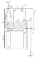
- FIGS. 1A, 1B and 1Care schematic illustrations of three operational modes of an infusion pump with a connectable air trap module, constructed and operative in accordance with a preferred embodiment of the present invention
- FIG. 1Dis a schematic illustration of an operational mode of an infusion pump with a connectable air trap module, constructed and operative in accordance with an embodiment of the present invention.
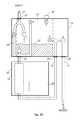
- FIGS. 2A, 2B and 2Care schematic illustrations of three operational modes of an infusion pump with an alternative connectable air trap module, constructed and operative in accordance with an alternative, preferred embodiment of the present invention
- FIG. 2Dis a schematic illustration of an operational mode of an infusion pump with a connectable air trap module, constructed and operative in accordance with an embodiment of the present invention
- FIGS. 3A and 3Bare isometric illustrations of an exemplary embodiment of air trap module of FIG. 1 connected to a pump;
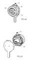
- FIGS. 4A and 4Bare isometric illustrations of the air trap module of FIG. 3 with a dial knob actuator in the front and an air trap chamber in the back;
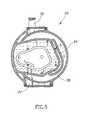
- FIG. 5is a back view illustration of the air chamber of FIG. 4B indicating the locations of the various valves in air trap module;
- FIG. 6Ais an exploded view of the elements of the air trap module of FIG. 3 ;
- FIG. 6Bis an isometric illustration of the some of the inner elements of FIG. 6A combined together;
- FIG. 6Cis a sectional view of the module of FIG. 6A (not exploded);
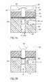
- FIGS. 7A and 7Bare schematic cross sectional illustrations of a typical valve in the air trap module of FIG. 3 , detailing the disengagement (open) and engagement (close) of a typical valve spool, respectively;
- FIG. 8is an isometric illustration of an undulating underside of a dial of the air trap module of FIG. 3 ;
- FIGS. 9A, 9B, 9C and 9Dare schematic illustrations of the fluid flow for each of a treatment, priming, venting and sterilization states, respectively.
- FIGS. 10A and 10Bare schematic illustrations of elements of the air trap module of FIG. 3 utilized in manufacture and, in particular, for the sterilization mode during manufacture.
- Applicantshave realized that adding a stand-alone air trap chamber, separate from the pump and as part of the tubing connecting the bag to the pump, may enable the air bubbles to be collected in one place, to be safely removed.
- the fluid already in the tubesmay be utilized to push the air out of the air trap chamber and into a closed container, thereby removing the air without detaching the tubes from the pump or from the patient and without the need to spill fluid to refill the tubes.
- the lack of spillagerepresents a significant savings, not to mention the fact that, with little or no spillage, the dosage prescribed is the dosage received.
- bypass fluidmay be returned to the air trap chamber to push the air out of the air trap.
- the pumpmay pull the air out of the air trap chamber directly to the vent. In both cases, the air trap is refilled with fresh fluid.
- the apparatus described belowis particularly relevant for chemotherapy applications, where spillage is of great concern; however, it will be appreciated that the apparatus may be utilized for all types of infusion operations since the apparatus of the present invention may maintain a closed system which may minimize patient contamination. It will also minimize the time needed to remove air from the IV system.
- FIGS. 1A, 1B and 1Cillustrate three alternate operational modes of an infusion pump 10 with a connectable air trap module 12 , connected to the tubes providing fluids, such as chemotherapy fluids, to the patient.
- Pump 10may operate on a “set interface” 14 , which may be a portion of the tubes capable of receiving the pumping action. Pump 10 may also provide an air bubble detector (not shown) to stop the pump action if an air bubble is detected in set interface 14 .
- the air trap chambermay be combined with the set interface as one physical unit Reference is further made to FIG. 1D , which is substantially similar to FIG. 1A further including air bubble detector 50 .
- Air trap module 12may be connected to set interface 14 , prior to pump 10 and above it, thereby to receive air flowing in the supply line 21 .
- Air trap module 12may have an air trap chamber 16 and a vent 18 therein, as well as a plurality of valves to control the flow of fluid into and out of air trap chamber 16 and to control the flow of air out of air trap chamber 16 .
- FIGS. 1A, 1B and 1Cthere are 7 valves, labeled 1 - 7 .
- FIGS. 2A, 2B and 2Cdescribed hereinbelow, there are 4 valves.
- air trap module 12may also have four line connections, a supply connection 20 to a supply line 21 , a set interface connection 22 to tubing connected to set interface 14 , a return connection 24 connectable to a return line 25 connected after set interface 14 and a patient connection 26 connectable to a patient line 27 connectable to the patient.
- Air trap module 12 of FIG. 1may have 7 valves (indicated by circles), to control the fluid and air flow through the various lines.
- the 7 valvesmay be a supply line valve 1 controlling supply line 21 into air trap chamber 16 , an upper valve 2 controlling fluid (or accumulated fumes) flowing from the top of air trap chamber 16 , a patient valve 3 controlling fluid flow from return line 25 into patient line 27 , a lower valve 4 controlling fluid flow into set interface 14 , a bypass valve 5 controlling flow from supply line 21 into an internal bypass line 29 , a return valve 6 controlling flow from return line 25 back into air trap chamber 16 and a venting valve 7 venting air out of air trap chamber 16 .
- a treatment mode shown in FIG. 1Aduring which the fluid (chemotherapy or otherwise) may be provided to the patient
- a priming mode shown in FIG. 1Bduring which the various tubes may be filled completely with fluid
- a venting mode shown in FIG. 1Cduring which toxic air, in the chemotherapy case, trapped in air trap chamber 16 may be pushed out of vent 18 and into any suitably closed unit, such as a syringe 19 (shown), an empty bag, etc., thereby to keep the toxic air from affecting any of the staff.
- vent 18 and its associated venting valve 7may be located generally at the top of air trap chamber 16 , thereby to allow the air to rise and to be pulled out without squeezing air trap chamber 16 .
- all valves 1 - 7may be open, thereby connecting all internal passages. This may allow free flow of sterilization gases throughout module 16 , a typical requirement for an ETO type of sterilization. Typically, this mode may be active only during manufacturing or by a specially trained technician and may no longer be accessible once regular operation begins.
- fluidmay flow from the supply line, through pump 10 , to the patient.
- supply valve 1is open (indicated by an open circle) for fluid to flow from supply line 21 into air trap chamber 16 and lower valve 4 is open for fluid to flow out of air trap chamber 16 and into set interface 14 .
- air bubbles flowing with the fluidmay break away from the flow and may rise into air trap chamber 16 where they will start to accumulate.
- Patient valve 3is open for fluid to flow from return line 25 into patient line 27 . However, the remaining valves are closed (indicated by an X in the circle) to keep fluid from flowing to the wrong places.
- air trap chamber 16may have some fluid in it, as indicated by a fluid line 30 . Typically in this mode at least part of the air trap module is filled with fluid.
- fluidmay flow to fill up the lines, before the lines are attached to the patient. No air may be allowed to be in the system.
- air trap chamber 16may be filled fully with fluid such that the fluid will flow out of upper valve 2 directly to set interface 14 .
- supply valve 1is open for fluid to flow into air trap chamber 16 and patient valve 3 is also open for fluid to flow from return line 25 into patient line 27 . The remaining valves are closed. Fluid may be allowed to flow to the end of patient line 27 , in order to prime the system.
- the chemotherapy fluidmay generate gases which form air bubbles in the flow, typically as the fluid flows from supply line 21 .
- Air trap chamber 16may trap these gases and may fill up.
- FIG. 1Cshows a fluid line 32 in the lower portion of air trap chamber 16 .
- air trap chamber 16may be filled entirely with air.
- air bubblesmay start to flow through valve 4 until they enter set interface 14 , where they may be detected by the air bubble detector forming part of pump 10 .
- the air bubble detectormay shut off the action of pump 10 and may activate an alarm which may not stop until a member of the medical staff may come to shut it off.
- the staff membermay then switch air trap module 12 to the venting mode, to remove the air from air trap chamber 16 and from set interface 14 , as follows:
- bypass valve 5may provide fluid directly from supply line 21 through set interface 14 to return line 25 and return valve 6 may allow the fluid from return line 25 to flow back into air trap chamber 16 , thereby filling air trap chamber 16 with fluid (indicated by arrow 34 ) which, in turn, may push the toxic air through valve 7 and out vent 18 , preferably into a closed unit, such as syringe 19 .
- valvessupply valve 1 , lower valve 4 , upper valve 2 and patient valve 3 , are all closed, to keep the air from the patient.
- the present inventionmay flush undesired air out of air trap chamber 16 , without disengaging patient line 27 from the patient and without exposing staff members to any of the noxious air.
- FIGS. 2A, 2B and 2Cillustrate the same three modes as FIGS. 1A, 1B and 1C but for a four valve air trap module 40 . Similar items carry similar reference numerals. As in the previous embodiment, there is an air trap chamber 16 and there are four line connections 20 , 22 , 24 and 26 , connected as in the previous embodiment to line 21 , set interface 14 , return line 25 and patient line 27 , respectively. Reference is further made to FIG. 2D , which is substantially similar to FIG. 2A further including air bubble detector 50 .
- valves 41 - 44there may be four valves 41 - 44 to air trap module 40 , two controlling flow through air trap chamber 16 and two controlling the output flow, either to patient line 27 or to vent 18 .
- the two controlling flow through air trap chamber 16may be an upper valve 41 controlling fluid and air flowing from the top of air trap chamber 16 and a lower valve 42 controlling fluid flow from air trap chamber 16 into set interface 14 .
- the two controlling the outputmay be a patient valve 43 controlling fluid flow into the patient, and a venting valve 44 venting undesired air out of air trap module 40 .
- fluidmay flow directly from supply line 21 into air trap module 40 , being pulled into air trap module 40 by the operation of pump 10 .
- Lower valve 42is open for fluid to flow out of air trap module 40 and into set interface 14 .
- Patient valve 43is also open, for fluid to flow out of air trap module 40 and into patient line 27 . However, the remaining valves are closed.
- fluidmay flow to fill air trap module 40 such that the fluid may flow out of upper valve 41 directly to set interface 14 , through return line 25 , and into patient line 27 via patient valve 43 .
- fluidmay be allowed to flow to the end of patient line 27 , in order to prime the system.
- the airmay be pumped by pump 10 out of upper valve 41 , through return line 25 and out through vent 18 .
- lower valve 42 and patient valve 43are closed, to keep air from the patient, and upper valve 41 and vent valve 44 are opened.
- fluidwill begin to flow from supply line 21 , filling air trap chamber 16 and return line 25 , such that, once all of the air is removed, the system may return to the treatment mode.
- the air detector of pump 10may be shut off during removal of the air, so as not to detect the air flowing past the pump during the removal process.
- Venting valve 7 or 44may be any suitable venting valve.
- itmay have a buoy to prevent the flow fluid out vent 18 once all of the air has been removed. If the buoy is a one directional buoy, the buoy may rise up the valve as the fluids rise in air chamber 16 and may block the opening of valve 7 or 44 as a result. This may keep fluids from being vented into the collection bag or syringe 19 . If the buoy is a two directional buoy, it may also prevent the return of existed fluids collected in a collection bag back to the air trap chamber system. Vent 18 may have a check valve, typically a swabbable valve connector, which may prevent accidental air discharge.
- air trap chamber 16has two valves, lower valve 4 or 42 and upper valve 2 or 41 to control the flow of fluid and/or air, depending on the operational mode. It will be appreciated that this enables air trap module 12 or 40 to handle both the presence of fluid and the presence of air without having to disconnect the patient from patient line 27 .
- air trap chamber 16may provide a buffer for collecting air. Its size may define the amount of air to be collected which, in turn, may define the amount of time the medical staff has between air removals. It is possible that, with the existence of this buffer per patient, the medical staff may be able to clear the various air trap chambers of a treatment room of patients before the various air trap chambers 16 fill up completely.
- air trap modules 12 and 40may be connected to any suitable type of pump.
- pump 10For each of the operational modes, pump 10 merely pumps in a forward direction; where the fluid or air goes is controlled by valves 1 - 7 or 41 - 44 .
- airmay reach the air detector of pump 10 which may cause pump 10 to stop operating.
- the air detector of pump 10may remain operative during venting of the air.
- valves 1 - 7 or 41 - 44may be implemented mechanically or electro-mechanically.
- mechanical configurationthere may preferably be a single actuator controlling all valves states.
- electro-mechanical caseeach valve may be separately programmed or they may be programmed to open or close as a group.
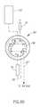
- FIGS. 3A and 3Billustrate an exemplary embodiment of the seven valve air trap module, implemented as a round unit with mechanically controlled valves.
- FIG. 3Aillustrates the air trap module 50 connected to the pump and FIG. 3B details how the connection to pump 10 is implemented.
- FIG. 3Ashows air trap module 50 , with vent 18 , connected to pump 10 with return line 25 and patient line 27 .
- FIG. 3Aalso shows a housing 52 for set interface 14 .
- FIG. 3Bshows a holder 54 forming part of a pump cradle used to hold pump 10 to an IV pole. Holder 54 may include flanges 55 to hold a stick-like portion 53 of air trap module 50 in place.
- stick 58may include an identification element 57 , such as a small magnet, therein and holder 54 may include an identifying sensor 59 , such as a Hall effect sensor. Sensor 59 may sense the presence or absence of identification element 57 and may provide its output to pump 10 . Element 57 and sensor 59 may enable automatic set recognition when air trap module 12 or 40 may be attached on to the pump.
- an identification element 57such as a small magnet
- holder 54may include an identifying sensor 59 , such as a Hall effect sensor.
- Sensor 59may sense the presence or absence of identification element 57 and may provide its output to pump 10 .
- Element 57 and sensor 59may enable automatic set recognition when air trap module 12 or 40 may be attached on to the pump.
- stick 53may allow the air trap module to be maintained in its correct position, upstream of the pump, allowing proper air accumulation in air chamber 16 .
- the internal air bubble sensor of pump 10may detect the bubbles and may stop pumping fluid, thereby protecting the patient.
- Stick 53is only one embodiment; other fastening elements may maintain proper air accumulation as well
- FIGS. 4A and 4Bdetail air trap module 50 with a dial knob 56 in front and an approximately oval shaped volume 58 functioning as air trap chamber 16 in the back.
- Volume 58may be of any size; for example, it may hold 2-4 ml.
- Module 50may also include fluid gauge minimum and maximum level indicators 60 and 62 , to provide an indication of the level of fluid in volume 58 .
- Volume 58may be formed of a clear plastic such that a user can see the air/fluid level at any time; thus, indicators 60 and 62 may simply mark the lowest and highest volume levels.
- module 50may be connected to a fluid level meter to better determine the air level in chamber 16 .
- the metermay be a floating ball.
- the air trap chambermay have an integrated electrical level meter which may trigger alarms and/or may trigger the start or stop of various modes.
- the knob in FIG. 4Amay be rotated only after the user pushes it slightly inwards. After releasing the knob, it will spring back to lock itself safely in one of the operating modes.
- Dial knob 56may have multiple positions, each controlling a different mode of operation. Four positions are shown, for infusion, venting, priming and an optional sterilization mode (labeled ETO). As will be described in more detail hereinbelow, as knob 56 moves from one position to another, the valves open and close to come to the states discussed hereinabove. It will be appreciated that knob 56 is a single handle which provides all modes. This may provide a simple and relatively reliable operation.
- FIG. 5indicates the locations of the various valves 1 - 7 in air trap module 50 . Note that venting valve 7 is near vent 18 , bypass valve 5 is above a bypass path 64 and patient valve 3 is above connection 26 to patient line 27 .
- FIGS. 6A, 6B and 6Cdetail air trap module 50 , where FIG. 6A provides the elements of air trap module 50 in exploded view, FIG. 6B illustrates the inner elements combined and FIG. 6C is a sectional view of the module.
- Module 50may comprise a top cover 70 , dial knob 56 , a dial 72 , seven valve spools 74 , a hive 76 of holes, a flexible seal membrane 78 , a main body 80 and a bottom cover 82 . Note that volume 58 is formed when bottom cover 82 is connected to body 80 .
- FIG. 6Bshows valve spools 74 positioned above dial 72 . Note the central cylinder, labeled 81 , within which dial knob 56 rotates. It will be appreciated that each valve spool 74 may move up and down within an associated hole 84 of hive 76 and may press against seal membrane 78 to open and close its associated valve. Dial 72 may be designed, as described hereinbelow, to press the appropriate set of valve spools 74 for each mode.
- Spool 74may be held in place by one of holes 84 in hive 76 and may be held against flexible seal membrane 78 .
- Dial 72may comprise an undulating underside 90 which may have recesses 92 and protrusions 94 , where protrusions 94 may press each spool 74 down into seal membrane 78 while recesses 92 may allow each spool 74 to rise, typically pushed back by seal membrane 78 .
- the arrangement of the recesses 92 and protrusions 94may determine which valves open and which close for each of the operational modes.
- a concentric valve configurationcomprising a first conduit 96 , optionally vertical, in the center of the valve module and a second conduit 98 , optionally horizontal, connected together via a circular ditch-like groove 100 .
- the top circular lips of conduit 96 and groove 100may be located underneath membrane 78 .
- recess 92may be above spool 74 and thus, spool 74 may not press against seal 78 .
- groove 100may be open and the two conduits 96 and 98 may be connected and fluid and/or air may flow therebetween.
- protrusion 94may engage spool 74 , thereby pushing it into seal membrane 78 which may then push against groove 100 , disconnecting the two conduits 96 and 98 and stopping the flow of fluid and/or air.
- FIG. 8illustrates undulating underside 90 of dial 72 .
- Underside 90may have a plurality of recesses 92 and protrusions 94 , not evenly spaced around dial 72 .
- the distance between neighboring protrusions 94may be a function of which valves 1 - 7 are open or closed for which mode.
- protrusions 94may enable the present invention to provide a double action safety feature, such as a make before break feature, for changing from one mode to another.
- recesses 92may be located such that, when turning from one mode to another, certain released spools 74 may be closed by their respective protrusions 94 before other spools 74 may be opened by their respective recesses 92 .
- Thismay enable one mode disengage completely before the next mode engages, which may be useful for the venting mode which may cause a buildup of pressure in air trap module 16 .
- This pressuremay be released when returning from venting mode back to treatment mode by ensuring that closed supply valve 1 will open (to release pressure back into supply line 21 instead of into the patient) before open return valve 6 is closed and closed patient valve 3 is opened.
- FIGS. 9A, 9B, 9C and 9Dillustrate the fluid flow for each of the treatment, priming, venting and sterilization states, respectively, for air trap module 50 .
- fluidflows from a fluid bag 110 to supply valve 1 , through chamber 58 to lower valve 4 through set interface 14 (operated on by pump 10 ) and return line 25 and from return line 25 to patient valve 3 .
- fluidflows from fluid bag 110 , to supply valve 1 , through chamber 58 to upper valve 2 , through set interface 14 and return line 25 to patient valve 3 and from there to patient line 27 .
- all valves 1 - 7are open to allow sterilization air to circulate through all of the tubing, air chamber 58 , and all manifolds and conduits.
- dial 72may have a protrusion 120 that, during assembly, may be aligned with an assembly recess 122 in top cover 70 . Moreover, dial 72 may have a flexible snap edge 124 which may be aligned, also during assembly, on top of an operating range edge 126 in hive 76 .
- protrusion 120may be part of cover 70 and assembly recess 122 may be part of dial 72 .
- air trap module 50may remain in the sterilization mode until first use, at which point the user may switch the dial to one of the operating modes.
- dial 72may move out of assembly recess 122 , resulting in snap edge 124 moving off of operating range edge 126 and into an operating range defined by range edge 126 and another range edge 127 .
- the described mechanismprevents switching the air trap module back to ETO mode once the user has switched it to one of the other operational modes (e.g. treatment, priming or venting).
- the other operational modese.g. treatment, priming or venting
- each valve in the air trap modulemay have its own electro mechanical actuator.
- the actuatorsmay be connected to a microcontroller which may be located in the module or in the pump.
- the microcontrollermay control the valves in a predefined manner, such as that described hereinabove or in accordance with any other manner or as programmed by a user.
- the electro mechanical valve actuatorsmay have a linear or rotary construction.
- the electro mechanical valve actuatorsmay be assembled in a separate assembly that may be snapped onto the air trap module. It may be constructed for multiple uses and may also have a secondary, manual actuator for when the electro mechanical actuator is not working.
- the pumpmay control the operation of the air trap module and may activate the various valves according to the modes discussed hereinabove.
- the air detector of the pumpmay detect the presence of air and may control the valves to change from the treatment to venting and back. It may also control the priming state.
- the air trap modulemay have 7 or 4 valves, as desired.
- the pumpmay drive an amount of fluid that is equivalent to the volume of air trap chamber 50 plus a small amount. This is a safety feature to prevent the pump from pushing the piston of the syringe out and spilling the medicine if the nurse forgets to stop the pump operation.
- the small amountis provided in case a small pressure is built up in the syringe, to ensure that all the air is removed. If the syringe is stuck, a pressure detector of the pump will alert of the pressure build up.
- the pressure to start moving itmay require a higher pressure.
- ittypically requires 1-2 levels of pressure to start the air drive to the syringe and a lower level of pressure to continue to drive it.
- the pumpmay require the medical staff to input the volume of the syringe or collecting bag, typically prior to the first air removal. The pump may then alert the medical staff after the total air removed (over the course of a few removals) may reach the syringe volume.
- air trap module 50may include a syringe holder to physically block the syringe from jumping out of vent 18 if the pump operation was not stopped in time and resulted in an over flow.
Landscapes
- Health & Medical Sciences (AREA)
- Heart & Thoracic Surgery (AREA)
- Vascular Medicine (AREA)
- Engineering & Computer Science (AREA)
- Anesthesiology (AREA)
- Biomedical Technology (AREA)
- Hematology (AREA)
- Life Sciences & Earth Sciences (AREA)
- Animal Behavior & Ethology (AREA)
- General Health & Medical Sciences (AREA)
- Public Health (AREA)
- Veterinary Medicine (AREA)
- Emergency Medicine (AREA)
- Infusion, Injection, And Reservoir Apparatuses (AREA)
Abstract
Description
Claims (20)
Priority Applications (1)
| Application Number | Priority Date | Filing Date | Title |
|---|---|---|---|
| US13/640,519US9457158B2 (en) | 2010-04-12 | 2011-04-12 | Air trap for intravenous pump |
Applications Claiming Priority (3)
| Application Number | Priority Date | Filing Date | Title |
|---|---|---|---|
| US28285810P | 2010-04-12 | 2010-04-12 | |
| PCT/IB2011/051586WO2011128850A2 (en) | 2010-04-12 | 2011-04-12 | Air trap for intravenous pump |
| US13/640,519US9457158B2 (en) | 2010-04-12 | 2011-04-12 | Air trap for intravenous pump |
Related Parent Applications (1)
| Application Number | Title | Priority Date | Filing Date |
|---|---|---|---|
| PCT/IB2011/051586A-371-Of-InternationalWO2011128850A2 (en) | 2010-04-12 | 2011-04-12 | Air trap for intravenous pump |
Related Child Applications (1)
| Application Number | Title | Priority Date | Filing Date |
|---|---|---|---|
| US15/276,893ContinuationUS20170080146A1 (en) | 2010-04-12 | 2016-09-27 | Air trap for intravenous pump |
Publications (2)
| Publication Number | Publication Date |
|---|---|
| US20130116620A1 US20130116620A1 (en) | 2013-05-09 |
| US9457158B2true US9457158B2 (en) | 2016-10-04 |
Family
ID=44799102
Family Applications (2)
| Application Number | Title | Priority Date | Filing Date |
|---|---|---|---|
| US13/640,519Expired - Fee RelatedUS9457158B2 (en) | 2010-04-12 | 2011-04-12 | Air trap for intravenous pump |
| US15/276,893AbandonedUS20170080146A1 (en) | 2010-04-12 | 2016-09-27 | Air trap for intravenous pump |
Family Applications After (1)
| Application Number | Title | Priority Date | Filing Date |
|---|---|---|---|
| US15/276,893AbandonedUS20170080146A1 (en) | 2010-04-12 | 2016-09-27 | Air trap for intravenous pump |
Country Status (3)
| Country | Link |
|---|---|
| US (2) | US9457158B2 (en) |
| EP (1) | EP2558147A4 (en) |
| WO (1) | WO2011128850A2 (en) |
Families Citing this family (17)
| Publication number | Priority date | Publication date | Assignee | Title |
|---|---|---|---|---|
| IL165365A0 (en) | 2004-11-24 | 2006-01-15 | Q Core Ltd | Finger-type peristaltic pump |
| US8308457B2 (en) | 2004-11-24 | 2012-11-13 | Q-Core Medical Ltd. | Peristaltic infusion pump with locking mechanism |
| IL179234A0 (en) | 2006-11-13 | 2007-03-08 | Q Core Ltd | An anti-free flow mechanism |
| IL179231A0 (en) | 2006-11-13 | 2007-03-08 | Q Core Ltd | A finger-type peristaltic pump comprising a ribbed anvil |
| US8535025B2 (en) | 2006-11-13 | 2013-09-17 | Q-Core Medical Ltd. | Magnetically balanced finger-type peristaltic pump |
| US8371832B2 (en) | 2009-12-22 | 2013-02-12 | Q-Core Medical Ltd. | Peristaltic pump with linear flow control |
| US9457158B2 (en) | 2010-04-12 | 2016-10-04 | Q-Core Medical Ltd. | Air trap for intravenous pump |
| US9674811B2 (en) | 2011-01-16 | 2017-06-06 | Q-Core Medical Ltd. | Methods, apparatus and systems for medical device communication, control and localization |
| US9726167B2 (en) | 2011-06-27 | 2017-08-08 | Q-Core Medical Ltd. | Methods, circuits, devices, apparatuses, encasements and systems for identifying if a medical infusion system is decalibrated |
| JP2014527881A (en) | 2011-09-21 | 2014-10-23 | ベイヤー メディカル ケア インク. | Continuous multi-fluid pump device, drive and actuation system and method |
| US9855110B2 (en) | 2013-02-05 | 2018-01-02 | Q-Core Medical Ltd. | Methods, apparatus and systems for operating a medical device including an accelerometer |
| WO2014149013A2 (en)* | 2013-03-22 | 2014-09-25 | Özel Erkan | An infusion set that operates with an infusion pump, which restrains the flow of air from the serum set to the patient and prevents said air to mix with ambient air |
| US10507319B2 (en) | 2015-01-09 | 2019-12-17 | Bayer Healthcare Llc | Multiple fluid delivery system with multi-use disposable set and features thereof |
| EP4397335A3 (en) | 2019-01-30 | 2024-09-25 | Tessen Solutions Limited | A bubble trap device |
| ES2933693T3 (en) | 2019-11-18 | 2023-02-13 | Eitan Medical Ltd | Rapid test for medical pump |
| EP4188480A1 (en)* | 2020-07-29 | 2023-06-07 | Tessen Solutions Limited | Infusion apparatus |
| CN117643658B (en)* | 2024-01-30 | 2024-04-09 | 佳木斯大学 | Gynaecology's tumour nursing infusion pump safe portable device |
Citations (245)
| Publication number | Priority date | Publication date | Assignee | Title |
|---|---|---|---|---|
| US2056322A (en) | 1933-05-20 | 1936-10-06 | E C Atkins And Company | Globe valve |
| US2393838A (en) | 1943-11-10 | 1946-01-29 | Foundation For Clinical And Su | Drop by drop pump |
| US2743898A (en) | 1953-10-30 | 1956-05-01 | Exxon Research Engineering Co | Magnetic valve for control of fluid or fluidized solids flow |
| US2981115A (en) | 1958-12-03 | 1961-04-25 | Mefina Sa | Device for converting electric signals into mechanical displacements |
| US3443585A (en) | 1967-07-03 | 1969-05-13 | North American Rockwell | Magnetically operated multi-valve assembly |
| US3511583A (en) | 1968-09-24 | 1970-05-12 | Gen Motors Corp | Magnetic fluid actuating pump |
| US3677667A (en) | 1970-08-28 | 1972-07-18 | Clyde A Morrison | Peristaltic fluid pump |
| US3778195A (en) | 1972-07-20 | 1973-12-11 | G Bamberg | Pump for parenteral injections and the like |
| US3982725A (en) | 1974-06-27 | 1976-09-28 | Keystone International, Inc. | Valve actuator |
| US3982722A (en) | 1975-11-21 | 1976-09-28 | General Motors Corporation | Magnetic control valve |
| US4014318A (en) | 1973-08-20 | 1977-03-29 | Dockum James M | Circulatory assist device and system |
| US4039269A (en) | 1976-01-19 | 1977-08-02 | The Lynkeus Corporation | Flexible tube pump having linear cam actuation of distributor means |
| US4155362A (en) | 1976-01-26 | 1979-05-22 | Baxter Travenol Laboratories, Inc. | Method and apparatus for metered infusion of fluids |
| US4178138A (en) | 1976-05-05 | 1979-12-11 | Frank Iles | Cartridge for peristaltic pump |
| US4236880A (en) | 1979-03-09 | 1980-12-02 | Archibald Development Labs, Inc. | Nonpulsating IV pump and disposable pump chamber |
| US4270532A (en) | 1977-12-28 | 1981-06-02 | Siemens Aktiengesellschaft | Device for the pre-programmable infusion of liquids |
| US4290346A (en) | 1979-04-30 | 1981-09-22 | Abbott Laboratories | Intravenous pump chamber |
| US4320781A (en) | 1978-10-16 | 1982-03-23 | Regie Nationale Des Usines Renault | Three-way electrically-actuated hydraulic distributor |
| US4373525A (en) | 1980-02-12 | 1983-02-15 | Terumo Corporation | Method and apparatus for detecting occlusion in fluid-infusion tube of peristaltic type fluid-infusion pump |
| WO1984000691A1 (en) | 1982-08-12 | 1984-03-01 | American Hospital Supply Corp | Linear peristaltic pumping apparatus and disposable casette therefor |
| US4450375A (en) | 1982-11-12 | 1984-05-22 | Kiwi Coders Corporation | Piezoelectric fluid control device |
| US4479797A (en) | 1981-07-04 | 1984-10-30 | Terumo Corporation | Medication infusion device |
| US4489863A (en) | 1982-02-11 | 1984-12-25 | International Business Machines Corporation | Precision fluid dispense valve |
| JPS6043188A (en) | 1983-08-19 | 1985-03-07 | Hitachi Ltd | Liquid discharging device |
| US4650469A (en) | 1984-10-19 | 1987-03-17 | Deltec Systems, Inc. | Drug delivery system |
| EP0215249A1 (en) | 1985-08-05 | 1987-03-25 | Nikkiso Co., Ltd. | A transfusion apparatus |
| US4671792A (en) | 1986-02-18 | 1987-06-09 | American Hospital Supply Corporation | Pressure-regulating peristaltic pump |
| EP0225158A2 (en) | 1985-11-26 | 1987-06-10 | Imed Corporation | Dual mode I.V. infusion device |
| US4682135A (en) | 1985-04-03 | 1987-07-21 | Teijin Seiki Company Limited | Elastic support members for an electric actuator |
| US4725205A (en) | 1987-01-30 | 1988-02-16 | Fisher Scientific Group Inc. | Peristaltic pump with cam action compensator |
| US4728265A (en) | 1987-01-30 | 1988-03-01 | Fisher Scientific Group Inc. | Peristaltic pump with cam action compensator |
| US4741736A (en) | 1986-12-10 | 1988-05-03 | I-Flow Corporation | Programmable infusion pump |
| US4748003A (en) | 1986-03-11 | 1988-05-31 | Riley Medical Incorporated | Container for flash sterilization |
| US4755168A (en) | 1987-01-27 | 1988-07-05 | Pat Romanelli | Medical drainage pump with irrigation |
| EP0315312A1 (en) | 1987-11-02 | 1989-05-10 | Imed Corporation | Device and method for detecting a partial restriction |
| US4867744A (en) | 1987-05-21 | 1989-09-19 | Baxter International Inc. | Peristaltic linear pump with contoured rollers |
| FR2632529A1 (en) | 1988-06-14 | 1989-12-15 | Celsa Composants Electr Sa | Improvements to drug injection apparatuses with a removable container |
| US4893991A (en) | 1987-05-27 | 1990-01-16 | Heminway James F | Method and means for improving efficiency of peristaltic pumps |
| US4927411A (en) | 1987-05-01 | 1990-05-22 | Abbott Laboratories | Drive mechanism for disposable fluid infusion pumping cassette |
| US4954256A (en) | 1989-05-15 | 1990-09-04 | Pall Corporation | Hydrophobic membranes |
| US4954046A (en) | 1989-12-08 | 1990-09-04 | Imed Corporation | Peristaltic pump with mechanism for maintaining linear flow |
| US4978335A (en) | 1989-09-29 | 1990-12-18 | Medex, Inc. | Infusion pump with bar code input to computer |
| EP0429866A1 (en) | 1989-11-02 | 1991-06-05 | Ivac Corporation | Apparatus and method for measuring pressure in a fluid line for detecting an occlusion in said fluid line |
| US5061241A (en)* | 1989-01-19 | 1991-10-29 | Stephens Jr Harry W | Rapid infusion device |
| WO1991016933A1 (en) | 1990-05-04 | 1991-11-14 | Block Medical, Inc. | Disposable infusion apparatus with peristaltic pump |
| US5074756A (en) | 1988-05-17 | 1991-12-24 | Patient Solutions, Inc. | Infusion device with disposable elements |
| US5078683A (en) | 1990-05-04 | 1992-01-07 | Block Medical, Inc. | Programmable infusion system |
| US5088904A (en) | 1989-07-24 | 1992-02-18 | Terumo Kabushiki Kaisha | Transfusion pump |
| US5096385A (en) | 1989-11-08 | 1992-03-17 | Ivac Corporation | Method and system for upstream occlusion detection |
| US5103211A (en) | 1989-11-02 | 1992-04-07 | Ivac Corporation | Apparatus for detecting fluid line occlusion |
| EP0483794A1 (en) | 1990-10-31 | 1992-05-06 | Terumo Kabushiki Kaisha | Transfusion pump |
| US5151019A (en) | 1988-11-04 | 1992-09-29 | Danby Medical Engineering Ltd. | Pumping device having inlet and outlet valves adjacent opposed sides of a tube deforming device |
| US5165874A (en) | 1990-05-04 | 1992-11-24 | Block Medical, Inc. | Disposable infusion apparatus and peristaltic pump for use therewith |
| US5213483A (en) | 1991-06-19 | 1993-05-25 | Strato Medical Corporation | Peristaltic infusion pump with removable cassette and mechanically keyed tube set |
| US5222946A (en) | 1986-03-04 | 1993-06-29 | Deka Products Limited Partnership | Compact intravenous fluid delivery system |
| US5246347A (en) | 1988-05-17 | 1993-09-21 | Patients Solutions, Inc. | Infusion device with disposable elements |
| US5257978A (en) | 1992-07-14 | 1993-11-02 | Habley Medical Technology Corporation | IV safety module |
| WO1993025816A1 (en) | 1992-06-09 | 1993-12-23 | Sabratek Corporation | Programmable infusion pump with interchangeable tubing |
| US5286176A (en) | 1993-05-06 | 1994-02-15 | The United States Of America As Represented By The Secretary Of The Navy | Electromagnetic pump |
| US5290158A (en) | 1989-07-31 | 1994-03-01 | Terumo Kabushiki Kaisha | Peristaltic pump |
| WO1994008647A1 (en) | 1992-10-15 | 1994-04-28 | The General Hospital Corporation | An infusion pump with an electronically loadable drug library |
| US5308333A (en) | 1991-12-06 | 1994-05-03 | Baxter International Inc. | Air eliminating intravenous infusion pump set |
| JPH06169992A (en) | 1992-12-01 | 1994-06-21 | Sharp Corp | Peristaltic infusion pump |
| US5338157A (en) | 1992-09-09 | 1994-08-16 | Pharmacia Deltec, Inc. | Systems and methods for communicating with ambulatory medical devices such as drug delivery devices |
| US5429485A (en) | 1992-12-18 | 1995-07-04 | Minnesota Mining And Manufacturing Company | Plural inlet pumping cassette with integral manifold |
| WO1996003168A1 (en) | 1994-07-27 | 1996-02-08 | Sims Deltec, Inc. | Occlusion detection system for an infusion pump |
| US5499969A (en) | 1992-02-05 | 1996-03-19 | Nestle S.A. | Microsurgical cassette |
| US5509439A (en) | 1992-05-28 | 1996-04-23 | Atos S.P.A. | Electromagnetically controlled operating device in particular for valves and electrohydraulic applications |
| US5527295A (en) | 1995-02-22 | 1996-06-18 | Wing; Michael L. | Gravitational, magnetic, floating ball valve |
| US5542826A (en) | 1994-09-12 | 1996-08-06 | Ivac Corporation | Fluid delivery system with mounting linkage |
| WO1996030679A1 (en) | 1995-03-27 | 1996-10-03 | Zevex, Inc. | Pinch clip occluder for infusion sets |
| US5569188A (en) | 1995-04-11 | 1996-10-29 | Mackool; Richard J. | Apparatus for controlling fluid flow through a surgical instrument and the temperature of an ultrasonic instrument |
| US5575631A (en) | 1996-03-12 | 1996-11-19 | Ahmad-Maher Moubayed | Curvilinear peristaltic pump |
| US5575309A (en) | 1993-04-03 | 1996-11-19 | Blp Components Limited | Solenoid actuator |
| US5577891A (en) | 1993-11-30 | 1996-11-26 | Instech Laboratories, Inc. | Low power portable resuscitation pump |
| US5593134A (en) | 1995-02-21 | 1997-01-14 | Applied Power Inc. | Magnetically assisted piezo-electric valve actuator |
| US5601420A (en) | 1994-09-12 | 1997-02-11 | Ivac Medical Systems, Inc. | Interlock, latching, and retaining mechanism for an infusion pump |
| US5628619A (en) | 1995-03-06 | 1997-05-13 | Sabratek Corporation | Infusion pump having power-saving modes |
| US5658250A (en) | 1993-07-13 | 1997-08-19 | Sims Deltec, Inc. | Systems and methods for operating ambulatory medical devices such as drug delivery devices |
| US5658252A (en) | 1993-11-22 | 1997-08-19 | Sims Deltec, Inc. | Drug pump including pressure plate and tube |
| US5660529A (en) | 1994-12-06 | 1997-08-26 | Mcgaw, Inc. | Linear peristaltic pump with reshaping fingers interdigitated with pumping elements |
| WO1997034084A1 (en) | 1996-03-12 | 1997-09-18 | Moubayed Ahmad Maher | Peristaltic pump with pinch fingers for providing complete occlusion |
| US5669877A (en) | 1994-03-07 | 1997-09-23 | Sims Deltec, Inc. | Systems and methods for automated testing of medical equipment |
| US5683233A (en) | 1996-10-18 | 1997-11-04 | Moubayed; Ahmad-Maher | Non-rolling type peristaltic pump having pressure plate mounted tube biasing means |
| WO1998004301A1 (en) | 1996-07-25 | 1998-02-05 | Alaris Medical Systems, Inc. | Infusion device with disposable elements |
| FR2753236A1 (en) | 1996-09-10 | 1998-03-13 | Conseilray Sa | MINIATURE PERISTALTIC PUMP |
| WO1998013080A2 (en) | 1996-08-14 | 1998-04-02 | Sims Deltec, Inc. | Free-flow protection devices and methods |
| US5742519A (en) | 1994-08-19 | 1998-04-21 | Spectrel Partners, L.L.C. | Integrated systems for testing and certifying the physical, functional, and electrical performance of IV pumps |
| US5782805A (en) | 1996-04-10 | 1998-07-21 | Meinzer; Randolph | Medical infusion pump |
| US5788669A (en) | 1995-11-22 | 1998-08-04 | Sims Deltec, Inc. | Pump tracking system |
| US5791881A (en) | 1996-10-18 | 1998-08-11 | Moubayed; Ahmad-Maher | Curvilinear peristaltic pump with occlusion detection means |
| EP0858812A2 (en) | 1997-02-17 | 1998-08-19 | Micrel, Microelectronic Applications Center Ltd. | Linear peristaltic pump |
| US5803712A (en) | 1988-05-17 | 1998-09-08 | Patient Solutions, Inc. | Method of measuring an occlusion in an infusion device with disposable elements |
| US5807322A (en) | 1994-03-21 | 1998-09-15 | Graseby Medical Limited | Pumping and pressure detection using flexible tubes |
| WO1998047551A1 (en) | 1997-04-18 | 1998-10-29 | Societe Des Produits Nestle S.A. | Peristaltic pump |
| US5876370A (en) | 1995-10-11 | 1999-03-02 | Sims Deltec, Inc. | Intermittent fluid delivery apparatus and method |
| US5896076A (en) | 1997-12-29 | 1999-04-20 | Motran Ind Inc | Force actuator with dual magnetic operation |
| US5909724A (en) | 1996-03-29 | 1999-06-08 | Mazda Motor Corporation | Engine control method |
| US5924852A (en) | 1996-03-12 | 1999-07-20 | Moubayed; Ahmad-Maher | Linear peristaltic pump |
| US5935099A (en) | 1992-09-09 | 1999-08-10 | Sims Deltec, Inc. | Drug pump systems and methods |
| US5943633A (en) | 1996-01-05 | 1999-08-24 | Sabratek Corporation | Automatic infusion pump tester |
| WO1999058178A1 (en) | 1998-05-13 | 1999-11-18 | Infutec Medical Systems Ltd. | Infusion pump calibration device and method |
| US5996964A (en) | 1997-05-19 | 1999-12-07 | Q-Core Ltd. | Magnetic flow controller |
| US6095189A (en) | 1997-05-19 | 2000-08-01 | Q-Core Ltd. | Magnetic valve |
| EP1031358A1 (en) | 1999-02-23 | 2000-08-30 | Fresenius Vial SA | Control procedure for a linear peristaltic pump |
| US6164921A (en) | 1998-11-09 | 2000-12-26 | Moubayed; Ahmad Maher | Curvilinear peristaltic pump having insertable tubing assembly |
| US6165874A (en) | 1997-07-03 | 2000-12-26 | The United States Of America As Represented By The Administrator Of The National Aeronautics And Space Administration | Method for growth of crystal surfaces and growth of heteroepitaxial single crystal films thereon |
| US6213723B1 (en) | 1996-06-24 | 2001-04-10 | Baxter International Inc. | Volumetric infusion pump |
| US6213739B1 (en) | 1997-01-17 | 2001-04-10 | Niagara Pump Corporation | Linear peristaltic pump |
| US6234773B1 (en) | 1994-12-06 | 2001-05-22 | B-Braun Medical, Inc. | Linear peristaltic pump with reshaping fingers interdigitated with pumping elements |
| US6241704B1 (en) | 1901-11-22 | 2001-06-05 | Sims Deltec, Inc. | Drug pump systems and methods |
| WO2001039816A2 (en) | 1999-12-01 | 2001-06-07 | B. Braun Medical, Inc. | Improved security infusion pump with bar code reader |
| US6261262B1 (en) | 1997-06-12 | 2001-07-17 | Abbott Laboratories | Pump with anti-free flow feature |
| US6280408B1 (en) | 1992-11-09 | 2001-08-28 | Anatole J. Sipin | Controlled fluid transfer system |
| WO2001065232A1 (en) | 2000-02-28 | 2001-09-07 | Alaris Medical Systems, Inc. | Force sensor assembly for an infusion pump |
| US20010029321A1 (en) | 2000-02-25 | 2001-10-11 | Klemens Beetz | System for patient monitoring |
| US6339410B1 (en) | 1997-07-22 | 2002-01-15 | Tellassist, Inc. | Apparatus and method for language translation between patient and caregiver, and for communication with speech deficient patients |
| JP2002057738A (en) | 2000-08-10 | 2002-02-22 | Nec Corp | Frame transfer device, frame transfer method and frame transfer system |
| WO2002036044A2 (en) | 2000-10-31 | 2002-05-10 | B. Braun Medical, Inc. | Patient medication iv delivery pump with wireless communication to a hospital information management system |
| WO2002038204A2 (en) | 2000-11-07 | 2002-05-16 | Baxter International Inc. | Occlusion detection method and system for ambulatory drug infusion pump |
| US20020056675A1 (en) | 2000-08-31 | 2002-05-16 | Ramesh Hegde | Gas vent filter construction incorporating a hollow fiber membrane assembly |
| WO2002049509A2 (en) | 2000-12-21 | 2002-06-27 | Insulet Corporation | Medical apparatus remote control and method |
| DE10118086A1 (en) | 2000-12-23 | 2002-07-11 | Ingolf Jasch | Device, especially hose pump, for high volume transport, dosing, compression and mixing of media or material, uses three or more linearly arranged moving stamping elements controlled to move fluid along a hose |
| US6422057B1 (en) | 1998-09-29 | 2002-07-23 | Deltec, Inc. | Drug pump testing system and methods |
| WO2002068015A2 (en) | 2001-02-22 | 2002-09-06 | Insulet Corporation | Modular infusion device and method |
| US6450773B1 (en) | 2001-03-13 | 2002-09-17 | Terabeam Corporation | Piezoelectric vacuum pump and method |
| US20020156402A1 (en) | 1998-06-16 | 2002-10-24 | Philippe-Guy E. Woog | Sonic therapeutic machine for the body |
| US20020165503A1 (en) | 2001-05-04 | 2002-11-07 | Morris Matthew G. | Medical instrument flow stop interface |
| US20030034887A1 (en) | 2001-03-12 | 2003-02-20 | Crabtree Timothy L. | Article locator system |
| US20030040700A1 (en) | 2001-07-31 | 2003-02-27 | Scott Laboratories, Inc. | Apparatuses and methods for providing IV infusion administration |
| US6537244B2 (en) | 1999-01-19 | 2003-03-25 | Assistive Technology Products, Inc. | Methods and apparatus for delivering fluids |
| WO2003027503A1 (en) | 2001-09-24 | 2003-04-03 | Digipump Ltd. | Piezoelectric pump |
| US20030065536A1 (en) | 2001-08-13 | 2003-04-03 | Hansen Henrik Egesborg | Portable device and method of communicating medical data information |
| US20030109988A1 (en) | 2001-10-12 | 2003-06-12 | Geissler Randolph K. | Three-dimensional GPS-assisted tracking device |
| US20030140928A1 (en) | 2002-01-29 | 2003-07-31 | Tuan Bui | Medical treatment verification system and method |
| US20030141981A1 (en) | 2002-01-29 | 2003-07-31 | Tuan Bui | System and method for operating medical devices |
| US6622542B2 (en) | 2001-03-20 | 2003-09-23 | Therox, Inc. | Bubble detector and method of use thereof |
| US20030182586A1 (en) | 2002-03-20 | 2003-09-25 | Kabushiki Kaisha Toshiba | Information-processing apparatus having a user-switching function and user-switching method for use in the apparatus |
| WO2003080158A1 (en) | 2002-03-21 | 2003-10-02 | Hospira, Inc. | Pump and tube set thereof |
| EP1350955A2 (en) | 2002-04-05 | 2003-10-08 | Sigma International | Peristaltic pump |
| US6692241B2 (en) | 2000-08-14 | 2004-02-17 | Terumo Kabushiki Kaisha | Infusion pump |
| US6733476B2 (en) | 2001-04-13 | 2004-05-11 | Medtronic, Inc. | Implantable drug delivery device with peristaltic pump having a bobbin roller assembly |
| JP2004141418A (en) | 2002-10-24 | 2004-05-20 | Top:Kk | Cassette for infusion pump |
| WO2004070548A2 (en) | 2003-02-01 | 2004-08-19 | Baxter International Inc. | System and method for verifying medical device operational parameters |
| US20040167804A1 (en) | 2002-04-30 | 2004-08-26 | Simpson Thomas L.C. | Medical data communication notification and messaging system and method |
| US20040172222A1 (en) | 2002-01-29 | 2004-09-02 | Simpson Thomas L. C. | System and method for notification and escalation of medical data |
| US20040181314A1 (en) | 2003-03-10 | 2004-09-16 | Zaleski John R. | Healthcare system supporting multiple network connected fluid administration pumps |
| US20040191112A1 (en) | 2003-03-31 | 2004-09-30 | Steris Inc. | Hydrogen peroxide injection system having closed-loop flow control |
| US20040204685A1 (en) | 2003-02-06 | 2004-10-14 | Medical Device Group, Inc. | Flexible IV site protector and method of using same |
| WO2004093648A2 (en) | 2003-04-18 | 2004-11-04 | Insulet Corporation | User interface for infusion pump remote controller and method of using the same |
| US20050001369A1 (en) | 2003-01-27 | 2005-01-06 | Cross Christopher Todd | Sheet material clamp |
| US20050055242A1 (en) | 2002-04-30 | 2005-03-10 | Bryan Bello | System and method for medical data tracking, analysis and reporting for healthcare system |
| US20050088409A1 (en) | 2002-02-28 | 2005-04-28 | Cees Van Berkel | Method of providing a display for a gui |
| US20050112001A1 (en) | 1999-04-19 | 2005-05-26 | Leybold Vakuum Gmbh, A Corporation Of Germany | Reciprocating piston drive mechanism |
| US6902549B2 (en) | 2002-07-01 | 2005-06-07 | Koninklijke Philips Electronics, N.V. | Fluid-advancing fiber |
| US20050171501A1 (en)* | 2004-02-03 | 2005-08-04 | Thomas Kelly | Intravenous solution producing systems and methods |
| US20050191196A1 (en) | 2000-09-22 | 2005-09-01 | Tanner Howard M. | Micro-volume infusion pump systems and methods of making the same |
| WO2005089263A2 (en) | 2004-03-13 | 2005-09-29 | B-Braun Medical, Inc. | Patient medication iv delivery pump with wireless communication to a hospital information management system |
| US20060051218A1 (en) | 2004-09-06 | 2006-03-09 | Herbert Harttig | Push-pull operated pump for a microfluidic system |
| US7018361B2 (en) | 2002-06-14 | 2006-03-28 | Baxter International Inc. | Infusion pump |
| US7022075B2 (en) | 1999-08-20 | 2006-04-04 | Zonare Medical Systems, Inc. | User interface for handheld imaging devices |
| US20060083644A1 (en) | 2004-10-12 | 2006-04-20 | Zumbrum Michael A | Dynamically tensioned peristaltic tubing pump |
| US7048720B1 (en) | 2004-05-03 | 2006-05-23 | Infusive Technologies, Llc | Multi-chamber, sequential dose dispensing syringe |
| WO2006056986A1 (en) | 2004-11-24 | 2006-06-01 | Q-Core Ltd. | Finger-type peristaltic pump |
| US20060173419A1 (en)* | 2005-02-02 | 2006-08-03 | Malcolm David R | Medical fluid delivery system and method relating to the same |
| US20060213249A1 (en) | 2005-03-28 | 2006-09-28 | Medrad, Inc. | Devices, systems and method for calibration of systems |
| US7122026B2 (en) | 2002-04-22 | 2006-10-17 | Medtronic, Inc. | Implantable infusion device with optimized peristaltic pump motor drive |
| US7131966B1 (en) | 1998-08-28 | 2006-11-07 | Yehuda Tamari | Automated means to remove air from venous blood during CPB |
| US7163385B2 (en) | 2002-11-21 | 2007-01-16 | California Institute Of Technology | Hydroimpedance pump |
| US20070032098A1 (en) | 2005-08-04 | 2007-02-08 | Staccato Communications, Inc. | Rechargeable wireless adapters |
| US20070048161A1 (en) | 2005-08-26 | 2007-03-01 | Ahmad-Maher Moubayed | Rotary axial peristaltic pumps and related methods |
| US20070060872A1 (en) | 2005-02-14 | 2007-03-15 | Hall W D | Apparatus and methods for analyzing body fluid samples |
| US20070135866A1 (en) | 2005-12-14 | 2007-06-14 | Welch Allyn Inc. | Medical device wireless adapter |
| US20070154336A1 (en) | 2005-11-17 | 2007-07-05 | Seiko Epson Corporation | Fluid transportation device |
| US20070217931A1 (en) | 2006-03-15 | 2007-09-20 | Estes Judson B | Peristaltic pump with field generator |
| WO2007133259A1 (en) | 2006-04-18 | 2007-11-22 | Gambro Bct, Inc. | Extracorporeal blood processing apparatus with pump balancing |
| US20080067462A1 (en) | 2006-08-09 | 2008-03-20 | Miller Pavel T | Stopcock With Swabbable Valve |
| US20080071251A1 (en) | 2006-09-18 | 2008-03-20 | Maas Medical, Llc | Method and system for controlled infusion of therapeutic substances |
| US20080095649A1 (en) | 2002-11-14 | 2008-04-24 | Zvi Ben-Shalom | Peristaltic Pump |
| WO2008059498A2 (en) | 2006-11-13 | 2008-05-22 | Q-Core Ltd. | A keying mechanism for a finger-type peristaltic infusion pump which is interconnected with one of a plurality of passive mechanical interfaces |
| WO2008059499A2 (en) | 2006-11-13 | 2008-05-22 | Q-Core Ltd. | An anti-free flow mechanism |
| WO2008059492A2 (en) | 2006-11-13 | 2008-05-22 | Q-Core Ltd. | A finger-type peristaltic pump comprising a ribbed anvil |
| WO2008059494A2 (en) | 2006-11-13 | 2008-05-22 | Q-Core Ltd. | Magnetically balanced finger-type peristaltic pump |
| WO2008059496A2 (en) | 2006-11-13 | 2008-05-22 | Q-Core Ltd. | Magnetic means of reducing the parasitic output of periodic systems and associated method |
| WO2008059493A2 (en) | 2006-11-13 | 2008-05-22 | Q-Core Ltd. | An open/close mechanism of passive mechanical interface and a finger-type peristaltic infusion pump |
| WO2008059495A2 (en) | 2006-11-13 | 2008-05-22 | Q-Core Ltd. | Gui for infusion pumps |
| US20080146995A1 (en)* | 2005-03-17 | 2008-06-19 | Smisson-Cartledge Biomedical Llc | Alignment and Attachment of a Heat Exchanger Cartridge to a Pump Device |
| US20080144560A1 (en) | 2006-12-15 | 2008-06-19 | Qualcomm Incorporated | Channel access scheme for ultra-wide band communication |
| WO2008130644A1 (en) | 2007-04-18 | 2008-10-30 | Ceramatec, Inc. | Fluid delivery device with flow rate control |
| US20080275307A1 (en) | 2004-02-06 | 2008-11-06 | Koninklijke Philips Electronics N.V. | Telemetry System With out of Range Notification Features |
| US20090088675A1 (en) | 2007-10-01 | 2009-04-02 | Baxter International Inc. | Fluid and air handling in blood and dialysis circuits |
| US7525432B2 (en) | 2004-09-15 | 2009-04-28 | Radarfind Corporation | Methods, identification tags and computer program products for automated location and monitoring of mobile devices |
| US20090163864A1 (en) | 2007-12-21 | 2009-06-25 | Breznock Eugene M | Method and apparatus for prevention of catheter air intake |
| US20090221964A1 (en) | 2004-11-24 | 2009-09-03 | Q-Core Medical Ltd | Peristaltic infusion pump with locking mechanism |
| US20090240201A1 (en) | 2006-11-13 | 2009-09-24 | Q-Core Medical Ltd | Magnetically balanced finger-type peristaltic pump |
| US20090270810A1 (en) | 2008-04-01 | 2009-10-29 | Debelser David | Security Features for a Medical Infusion Pump |
| US20090300507A1 (en) | 2008-05-27 | 2009-12-03 | Prabhu Raghavan | Wireless medical room control arrangement for control of a plurality of medical devices |
| US20100016781A1 (en) | 2005-08-29 | 2010-01-21 | Mizuo Nakayama | Iontophoresis device selecting drug to be administered on the basis of information form sensor |
| US20100082001A1 (en) | 2008-04-01 | 2010-04-01 | Kent Beck | Anti-free flow mechanism for enteral feeding pumps |
| US7698156B2 (en) | 2002-01-29 | 2010-04-13 | Baxter International Inc. | System and method for identifying data streams associated with medical equipment |
| US7704227B2 (en) | 2006-11-29 | 2010-04-27 | Medtronic Minimed, Inc. | Methods and apparatuses for detecting medical device acceleration, temperature, and humidity conditions |
| WO2010053702A1 (en) | 2008-11-07 | 2010-05-14 | Delphi Technologies, Inc. | Method of automatically programming an infusion pump |
| WO2010053703A1 (en) | 2008-11-07 | 2010-05-14 | Delphi Technologies, Inc. | Method of loading a drug library into an infusion pump |
| US20100168545A1 (en) | 2005-03-10 | 2010-07-01 | Dexcom, Inc. | System and methods for processing analyte sensor data for sensor calibration |
| WO2010091313A2 (en) | 2009-02-06 | 2010-08-12 | Zevex, Inc. | Automatic safety occluder |
| US20100211002A1 (en) | 2009-02-18 | 2010-08-19 | Davis David L | Electromagnetic infusion pump with integral flow monitor |
| US20100228223A1 (en)* | 2009-03-09 | 2010-09-09 | Williams Jeffrey B | Surgical fluid management system heater assembly and cartridge |
| US20100234708A1 (en) | 2009-03-16 | 2010-09-16 | Harvey Buck | Wirelessly configurable medical device for a broadcast network system |
| US20100279652A1 (en) | 2009-05-01 | 2010-11-04 | Apple Inc. | Remotely Locating and Commanding a Mobile Device |
| EP1557186B1 (en) | 2004-01-20 | 2010-11-17 | Sorin Group Deutschland GmbH | Automatic air removal system |
| US7840260B2 (en) | 2004-01-20 | 2010-11-23 | Yainax Medical, LLC | Iontophoretic intra-tympanic drug delivery system |
| US7892332B2 (en)* | 2007-10-01 | 2011-02-22 | Baxter International Inc. | Dialysis systems having air traps with internal structures to enhance air removal |
| US20110152831A1 (en) | 2009-12-22 | 2011-06-23 | Q-Core Medical Ltd | Peristaltic Pump with Linear Flow Control |
| US20110152772A1 (en) | 2009-12-22 | 2011-06-23 | Q-Core Medical Ltd | Peristaltic Pump with Bi-Directional Pressure Sensor |
| US20110148624A1 (en) | 2009-12-22 | 2011-06-23 | Mindray Ds Usa, Inc. | Systems and methods for determining a location of a medical device |
| US20110167133A1 (en) | 2010-01-05 | 2011-07-07 | Jain Praduman D | System, method, and device for medical device data capture and processing |
| US20110251856A1 (en) | 1998-11-09 | 2011-10-13 | Polymer Technology Systems, Inc. | Health monitoring and diagnostic device and network-based health assessment and medical records maintenance system |
| WO2011128850A2 (en) | 2010-04-12 | 2011-10-20 | Q Core Medical Ltd | Air trap for intravenous pump |
| US20110282291A1 (en) | 2008-09-19 | 2011-11-17 | C.R. Bard, Inc. | Medical device securement system |
| US20120059389A1 (en) | 2009-02-20 | 2012-03-08 | Loren Robert Larson | Implantable Micro-Generator Devices with Optimized Configuration, Methods of Use, Systems and Kits Therefor |
| US20120062387A1 (en) | 2010-09-10 | 2012-03-15 | Daniel Vik | Human interface device input filter based on motion |
| US20120136305A1 (en) | 2009-06-25 | 2012-05-31 | Nestec S.A. | Pinch clamp assembly for an infusion cassette |
| US8197235B2 (en) | 2009-02-18 | 2012-06-12 | Davis David L | Infusion pump with integrated permanent magnet |
| WO2012095829A2 (en) | 2011-01-16 | 2012-07-19 | Q-Core Medical Ltd. | Methods, apparatus and systems for medical device communication, control and localization |
| WO2012095827A1 (en) | 2011-01-16 | 2012-07-19 | Q-Core Medical Ltd. | Methods, apparatus and systems for metering fluid flow |
| US8241018B2 (en) | 2009-09-10 | 2012-08-14 | Tyco Healthcare Group Lp | Compact peristaltic medical pump |
| US20120241525A1 (en) | 2011-03-22 | 2012-09-27 | Gregory Borges | Displaying a barcode on a display of an infusion pump |
| US20130006666A1 (en) | 2011-07-01 | 2013-01-03 | Baxa Corporation | Systems and methods for intelligent patient interface device |
| WO2013001425A2 (en) | 2011-06-27 | 2013-01-03 | Q-Core Medical Ltd. | Methods, circuits, devices, apparatuses, encasements and systems for identifying if a medical infusion system is decalibrated |
| US20130046508A1 (en) | 2011-08-19 | 2013-02-21 | Kunal Sur | Pattern recognition system and method for the detection of stuck fluid droplets in a fluid delivery line of an infusion system |
| WO2013028704A1 (en) | 2011-08-23 | 2013-02-28 | Venetec International, Inc. | Medical article securement device |
| WO2013090748A1 (en) | 2011-12-16 | 2013-06-20 | University Of Virginia Patent Foundation | Channel separation device and related method thereof |
| US8489427B2 (en) | 2002-01-29 | 2013-07-16 | Baxter International Inc. | Wireless medical data communication system and method |
| US20130345623A1 (en) | 2012-06-22 | 2013-12-26 | Fresenius Medical Care Deutschland Gmbh | Device and method for creation and display of graphic coding specific for medical devices and medical treatments |
| US8672875B2 (en) | 2003-12-31 | 2014-03-18 | Carefusion 303, Inc. | Medication safety enhancement for secondary infusion |
| US20140222377A1 (en) | 2013-02-05 | 2014-08-07 | Q-Core Medical Ltd. | Methods, Apparatus and Systems for Operating a Medical Device including an Accelerometer |
| US20140276564A1 (en) | 2013-03-14 | 2014-09-18 | Baxter Healthcare Sa | Pump controller and pump for individualized healthcare use |
| US20140378901A1 (en) | 2013-06-23 | 2014-12-25 | Q-Core Medical Ltd. | Mechanical pump to tube interfaces, systems including the interfaces and methods for producing same |
| US20150038187A1 (en) | 2009-12-09 | 2015-02-05 | Texas Instruments Incorporated | Address space partitioning and filtering for discretionary wireless connection response |
| US20150073338A1 (en) | 2013-09-10 | 2015-03-12 | Covidien Lp | Enteral feeding pump with acceleration sensor and related methods therefor |
| US20150105726A1 (en) | 2012-07-19 | 2015-04-16 | Asante Solutions, Inc. | Infusion Pump System and Method |
| US20150137988A1 (en) | 2012-05-18 | 2015-05-21 | University Of Florida Research Foundation, Incorporated | Patient in-the-loop participatory care and monitoring |
| US20150141955A1 (en) | 2013-11-19 | 2015-05-21 | Timothy L. Ruchti | Infusion pump automation system and method |
| US20150172921A1 (en) | 2013-12-18 | 2015-06-18 | Medtronic Minimed, Inc. | Secure communication by user selectable communication range |
| US20150182694A1 (en) | 2013-12-26 | 2015-07-02 | Tandem Diabetes Care, Inc. | Safety processor for wireless control of a drug delivery device |
- 2011
- 2011-04-12USUS13/640,519patent/US9457158B2/ennot_activeExpired - Fee Related
- 2011-04-12EPEP11768544.6Apatent/EP2558147A4/ennot_activeWithdrawn
- 2011-04-12WOPCT/IB2011/051586patent/WO2011128850A2/enactiveApplication Filing
- 2016
- 2016-09-27USUS15/276,893patent/US20170080146A1/ennot_activeAbandoned
Patent Citations (346)
| Publication number | Priority date | Publication date | Assignee | Title |
|---|---|---|---|---|
| US6241704B1 (en) | 1901-11-22 | 2001-06-05 | Sims Deltec, Inc. | Drug pump systems and methods |
| US2056322A (en) | 1933-05-20 | 1936-10-06 | E C Atkins And Company | Globe valve |
| US2393838A (en) | 1943-11-10 | 1946-01-29 | Foundation For Clinical And Su | Drop by drop pump |
| US2743898A (en) | 1953-10-30 | 1956-05-01 | Exxon Research Engineering Co | Magnetic valve for control of fluid or fluidized solids flow |
| US2981115A (en) | 1958-12-03 | 1961-04-25 | Mefina Sa | Device for converting electric signals into mechanical displacements |
| US3443585A (en) | 1967-07-03 | 1969-05-13 | North American Rockwell | Magnetically operated multi-valve assembly |
| US3511583A (en) | 1968-09-24 | 1970-05-12 | Gen Motors Corp | Magnetic fluid actuating pump |
| US3677667A (en) | 1970-08-28 | 1972-07-18 | Clyde A Morrison | Peristaltic fluid pump |
| US3778195A (en) | 1972-07-20 | 1973-12-11 | G Bamberg | Pump for parenteral injections and the like |
| US4014318A (en) | 1973-08-20 | 1977-03-29 | Dockum James M | Circulatory assist device and system |
| US3982725A (en) | 1974-06-27 | 1976-09-28 | Keystone International, Inc. | Valve actuator |
| US3982722A (en) | 1975-11-21 | 1976-09-28 | General Motors Corporation | Magnetic control valve |
| US4039269A (en) | 1976-01-19 | 1977-08-02 | The Lynkeus Corporation | Flexible tube pump having linear cam actuation of distributor means |
| US4155362A (en) | 1976-01-26 | 1979-05-22 | Baxter Travenol Laboratories, Inc. | Method and apparatus for metered infusion of fluids |
| US4178138A (en) | 1976-05-05 | 1979-12-11 | Frank Iles | Cartridge for peristaltic pump |
| US4270532A (en) | 1977-12-28 | 1981-06-02 | Siemens Aktiengesellschaft | Device for the pre-programmable infusion of liquids |
| US4320781A (en) | 1978-10-16 | 1982-03-23 | Regie Nationale Des Usines Renault | Three-way electrically-actuated hydraulic distributor |
| US4236880A (en) | 1979-03-09 | 1980-12-02 | Archibald Development Labs, Inc. | Nonpulsating IV pump and disposable pump chamber |
| US4290346A (en) | 1979-04-30 | 1981-09-22 | Abbott Laboratories | Intravenous pump chamber |
| US4373525A (en) | 1980-02-12 | 1983-02-15 | Terumo Corporation | Method and apparatus for detecting occlusion in fluid-infusion tube of peristaltic type fluid-infusion pump |
| US4479797A (en) | 1981-07-04 | 1984-10-30 | Terumo Corporation | Medication infusion device |
| US4489863A (en) | 1982-02-11 | 1984-12-25 | International Business Machines Corporation | Precision fluid dispense valve |
| WO1984000691A1 (en) | 1982-08-12 | 1984-03-01 | American Hospital Supply Corp | Linear peristaltic pumping apparatus and disposable casette therefor |
| US4493706A (en) | 1982-08-12 | 1985-01-15 | American Hospital Supply Corporation | Linear peristaltic pumping apparatus and disposable casette therefor |
| US4450375A (en) | 1982-11-12 | 1984-05-22 | Kiwi Coders Corporation | Piezoelectric fluid control device |
| JPS6043188A (en) | 1983-08-19 | 1985-03-07 | Hitachi Ltd | Liquid discharging device |
| US4650469A (en) | 1984-10-19 | 1987-03-17 | Deltec Systems, Inc. | Drug delivery system |
| US4682135A (en) | 1985-04-03 | 1987-07-21 | Teijin Seiki Company Limited | Elastic support members for an electric actuator |
| EP0215249A1 (en) | 1985-08-05 | 1987-03-25 | Nikkiso Co., Ltd. | A transfusion apparatus |
| US4690673A (en) | 1985-11-26 | 1987-09-01 | Imed Corporation | Dual mode I.V. infusion device with distal sensor |
| EP0225158A2 (en) | 1985-11-26 | 1987-06-10 | Imed Corporation | Dual mode I.V. infusion device |
| US4671792A (en) | 1986-02-18 | 1987-06-09 | American Hospital Supply Corporation | Pressure-regulating peristaltic pump |
| US5222946A (en) | 1986-03-04 | 1993-06-29 | Deka Products Limited Partnership | Compact intravenous fluid delivery system |
| US4748003A (en) | 1986-03-11 | 1988-05-31 | Riley Medical Incorporated | Container for flash sterilization |
| US4741736A (en) | 1986-12-10 | 1988-05-03 | I-Flow Corporation | Programmable infusion pump |
| US4755168A (en) | 1987-01-27 | 1988-07-05 | Pat Romanelli | Medical drainage pump with irrigation |
| US4725205A (en) | 1987-01-30 | 1988-02-16 | Fisher Scientific Group Inc. | Peristaltic pump with cam action compensator |
| US4728265A (en) | 1987-01-30 | 1988-03-01 | Fisher Scientific Group Inc. | Peristaltic pump with cam action compensator |
| US4927411A (en) | 1987-05-01 | 1990-05-22 | Abbott Laboratories | Drive mechanism for disposable fluid infusion pumping cassette |
| US4867744A (en) | 1987-05-21 | 1989-09-19 | Baxter International Inc. | Peristaltic linear pump with contoured rollers |
| US4893991A (en) | 1987-05-27 | 1990-01-16 | Heminway James F | Method and means for improving efficiency of peristaltic pumps |
| US4836752A (en) | 1987-11-02 | 1989-06-06 | Fisher Scientific Company | Partial restriction detector |
| EP0315312A1 (en) | 1987-11-02 | 1989-05-10 | Imed Corporation | Device and method for detecting a partial restriction |
| US6312227B1 (en) | 1988-05-17 | 2001-11-06 | I-Flow Corp. | Infusion device with disposable elements |
| US6742992B2 (en) | 1988-05-17 | 2004-06-01 | I-Flow Corporation | Infusion device with disposable elements |
| US5803712A (en) | 1988-05-17 | 1998-09-08 | Patient Solutions, Inc. | Method of measuring an occlusion in an infusion device with disposable elements |
| US20080015506A1 (en) | 1988-05-17 | 2008-01-17 | Davis David L | Infusion device with disposable elements |
| US5246347A (en) | 1988-05-17 | 1993-09-21 | Patients Solutions, Inc. | Infusion device with disposable elements |
| US6146109A (en) | 1988-05-17 | 2000-11-14 | Alaris Medical Systems, Inc. | Infusion device with disposable elements |
| US5074756A (en) | 1988-05-17 | 1991-12-24 | Patient Solutions, Inc. | Infusion device with disposable elements |
| US5584667A (en) | 1988-05-17 | 1996-12-17 | Davis; David L. | Method of providing uniform flow from an infusion device |
| US20020094287A1 (en) | 1988-05-17 | 2002-07-18 | Davis David Lyle | Infusion device with disposable elements |
| FR2632529A1 (en) | 1988-06-14 | 1989-12-15 | Celsa Composants Electr Sa | Improvements to drug injection apparatuses with a removable container |
| US5151019A (en) | 1988-11-04 | 1992-09-29 | Danby Medical Engineering Ltd. | Pumping device having inlet and outlet valves adjacent opposed sides of a tube deforming device |
| USRE37074E1 (en) | 1988-11-04 | 2001-02-27 | Baxter Intl. Inc. | Pumping device having inlet and outlet valves adjacent opposed sides of a tube deforming device |
| US5061241A (en)* | 1989-01-19 | 1991-10-29 | Stephens Jr Harry W | Rapid infusion device |
| US4954256A (en) | 1989-05-15 | 1990-09-04 | Pall Corporation | Hydrophobic membranes |
| US5152680A (en) | 1989-07-24 | 1992-10-06 | Terumo Kabushiki Kaisha | Transfusion pump |
| US5088904A (en) | 1989-07-24 | 1992-02-18 | Terumo Kabushiki Kaisha | Transfusion pump |
| US5290158A (en) | 1989-07-31 | 1994-03-01 | Terumo Kabushiki Kaisha | Peristaltic pump |
| US4978335A (en) | 1989-09-29 | 1990-12-18 | Medex, Inc. | Infusion pump with bar code input to computer |
| US5103211A (en) | 1989-11-02 | 1992-04-07 | Ivac Corporation | Apparatus for detecting fluid line occlusion |
| EP0429866A1 (en) | 1989-11-02 | 1991-06-05 | Ivac Corporation | Apparatus and method for measuring pressure in a fluid line for detecting an occlusion in said fluid line |
| US5096385A (en) | 1989-11-08 | 1992-03-17 | Ivac Corporation | Method and system for upstream occlusion detection |
| US4954046A (en) | 1989-12-08 | 1990-09-04 | Imed Corporation | Peristaltic pump with mechanism for maintaining linear flow |
| WO1991016933A1 (en) | 1990-05-04 | 1991-11-14 | Block Medical, Inc. | Disposable infusion apparatus with peristaltic pump |
| US5078683A (en) | 1990-05-04 | 1992-01-07 | Block Medical, Inc. | Programmable infusion system |
| US5165874A (en) | 1990-05-04 | 1992-11-24 | Block Medical, Inc. | Disposable infusion apparatus and peristaltic pump for use therewith |
| EP0483794A1 (en) | 1990-10-31 | 1992-05-06 | Terumo Kabushiki Kaisha | Transfusion pump |
| US5219327A (en) | 1990-10-31 | 1993-06-15 | Terumo Kabushiki Kaisha | Transfusion pump |
| US5213483A (en) | 1991-06-19 | 1993-05-25 | Strato Medical Corporation | Peristaltic infusion pump with removable cassette and mechanically keyed tube set |
| US5308333A (en) | 1991-12-06 | 1994-05-03 | Baxter International Inc. | Air eliminating intravenous infusion pump set |
| US5499969A (en) | 1992-02-05 | 1996-03-19 | Nestle S.A. | Microsurgical cassette |
| US5509439A (en) | 1992-05-28 | 1996-04-23 | Atos S.P.A. | Electromagnetically controlled operating device in particular for valves and electrohydraulic applications |
| WO1993025816A1 (en) | 1992-06-09 | 1993-12-23 | Sabratek Corporation | Programmable infusion pump with interchangeable tubing |
| US5395320A (en) | 1992-06-09 | 1995-03-07 | Sabratek Corporation | Programmable infusion pump with interchangeable tubing |
| US5257978A (en) | 1992-07-14 | 1993-11-02 | Habley Medical Technology Corporation | IV safety module |
| US20080065016A1 (en) | 1992-09-09 | 2008-03-13 | Deltec, Inc. | Drug pump systems and methods |
| US20080065007A1 (en) | 1992-09-09 | 2008-03-13 | Deltec, Inc. | Drug pump systems and methods |
| US5338157A (en) | 1992-09-09 | 1994-08-16 | Pharmacia Deltec, Inc. | Systems and methods for communicating with ambulatory medical devices such as drug delivery devices |
| US5338157B1 (en) | 1992-09-09 | 1999-11-02 | Sims Deltec Inc | Systems and methods for communicating with ambulat |
| US6024539A (en) | 1992-09-09 | 2000-02-15 | Sims Deltec, Inc. | Systems and methods for communicating with ambulatory medical devices such as drug delivery devices |
| US5485408A (en) | 1992-09-09 | 1996-01-16 | Sims Deltec, Inc. | Pump simulation apparatus |
| US6475180B2 (en) | 1992-09-09 | 2002-11-05 | Sims Deltec, Inc. | Drug pump systems and methods |
| US7347836B2 (en) | 1992-09-09 | 2008-03-25 | Smiths Medical, Inc. | Drug pump systems and methods |
| US5935099A (en) | 1992-09-09 | 1999-08-10 | Sims Deltec, Inc. | Drug pump systems and methods |
| US7654976B2 (en) | 1992-09-09 | 2010-02-02 | Smiths Medical Asd, Inc. | Drug pump systems and methods |
| WO1994008647A1 (en) | 1992-10-15 | 1994-04-28 | The General Hospital Corporation | An infusion pump with an electronically loadable drug library |
| US6280408B1 (en) | 1992-11-09 | 2001-08-28 | Anatole J. Sipin | Controlled fluid transfer system |
| JPH06169992A (en) | 1992-12-01 | 1994-06-21 | Sharp Corp | Peristaltic infusion pump |
| US5429485A (en) | 1992-12-18 | 1995-07-04 | Minnesota Mining And Manufacturing Company | Plural inlet pumping cassette with integral manifold |
| US5575309A (en) | 1993-04-03 | 1996-11-19 | Blp Components Limited | Solenoid actuator |
| US5286176A (en) | 1993-05-06 | 1994-02-15 | The United States Of America As Represented By The Secretary Of The Navy | Electromagnetic pump |
| US5658250A (en) | 1993-07-13 | 1997-08-19 | Sims Deltec, Inc. | Systems and methods for operating ambulatory medical devices such as drug delivery devices |
| US5658252A (en) | 1993-11-22 | 1997-08-19 | Sims Deltec, Inc. | Drug pump including pressure plate and tube |
| US5577891A (en) | 1993-11-30 | 1996-11-26 | Instech Laboratories, Inc. | Low power portable resuscitation pump |
| US5669877A (en) | 1994-03-07 | 1997-09-23 | Sims Deltec, Inc. | Systems and methods for automated testing of medical equipment |
| US5807322A (en) | 1994-03-21 | 1998-09-15 | Graseby Medical Limited | Pumping and pressure detection using flexible tubes |
| WO1996003168A1 (en) | 1994-07-27 | 1996-02-08 | Sims Deltec, Inc. | Occlusion detection system for an infusion pump |
| US5695473A (en) | 1994-07-27 | 1997-12-09 | Sims Deltec, Inc. | Occlusion detection system for an infusion pump |
| US5935106A (en) | 1994-07-27 | 1999-08-10 | Sims Deltec, Inc. | Occlusion detection system for an infusion pump |
| US5742519A (en) | 1994-08-19 | 1998-04-21 | Spectrel Partners, L.L.C. | Integrated systems for testing and certifying the physical, functional, and electrical performance of IV pumps |
| US5601420A (en) | 1994-09-12 | 1997-02-11 | Ivac Medical Systems, Inc. | Interlock, latching, and retaining mechanism for an infusion pump |
| US5542826A (en) | 1994-09-12 | 1996-08-06 | Ivac Corporation | Fluid delivery system with mounting linkage |
| US6234773B1 (en) | 1994-12-06 | 2001-05-22 | B-Braun Medical, Inc. | Linear peristaltic pump with reshaping fingers interdigitated with pumping elements |
| US5888052A (en) | 1994-12-06 | 1999-03-30 | Mcgraw, Inc. | Linear peristaltic pump with reshaping fingers intedigitated with pumping elements |
| US5660529A (en) | 1994-12-06 | 1997-08-26 | Mcgaw, Inc. | Linear peristaltic pump with reshaping fingers interdigitated with pumping elements |
| US5593134A (en) | 1995-02-21 | 1997-01-14 | Applied Power Inc. | Magnetically assisted piezo-electric valve actuator |
| US5527295A (en) | 1995-02-22 | 1996-06-18 | Wing; Michael L. | Gravitational, magnetic, floating ball valve |
| US5628619A (en) | 1995-03-06 | 1997-05-13 | Sabratek Corporation | Infusion pump having power-saving modes |
| US5791880A (en) | 1995-03-06 | 1998-08-11 | Sabratek Corporation | Infusion pump having power-saving modes |
| US5810323A (en) | 1995-03-27 | 1998-09-22 | Zevex, Inc. | Pinch clip occluder for infusion sets |
| WO1996030679A1 (en) | 1995-03-27 | 1996-10-03 | Zevex, Inc. | Pinch clip occluder for infusion sets |
| US5704584A (en) | 1995-03-27 | 1998-01-06 | Zevex, Inc. | Pinch clip occluder for infusion sets |
| US5569188A (en) | 1995-04-11 | 1996-10-29 | Mackool; Richard J. | Apparatus for controlling fluid flow through a surgical instrument and the temperature of an ultrasonic instrument |
| US5876370A (en) | 1995-10-11 | 1999-03-02 | Sims Deltec, Inc. | Intermittent fluid delivery apparatus and method |
| US5788669A (en) | 1995-11-22 | 1998-08-04 | Sims Deltec, Inc. | Pump tracking system |
| US5943633A (en) | 1996-01-05 | 1999-08-24 | Sabratek Corporation | Automatic infusion pump tester |
| US5575631A (en) | 1996-03-12 | 1996-11-19 | Ahmad-Maher Moubayed | Curvilinear peristaltic pump |
| US5924852A (en) | 1996-03-12 | 1999-07-20 | Moubayed; Ahmad-Maher | Linear peristaltic pump |
| WO1997034084A1 (en) | 1996-03-12 | 1997-09-18 | Moubayed Ahmad Maher | Peristaltic pump with pinch fingers for providing complete occlusion |
| US5909724A (en) | 1996-03-29 | 1999-06-08 | Mazda Motor Corporation | Engine control method |
| US5782805A (en) | 1996-04-10 | 1998-07-21 | Meinzer; Randolph | Medical infusion pump |
| US6213723B1 (en) | 1996-06-24 | 2001-04-10 | Baxter International Inc. | Volumetric infusion pump |
| WO1998004301A1 (en) | 1996-07-25 | 1998-02-05 | Alaris Medical Systems, Inc. | Infusion device with disposable elements |
| US6110153A (en) | 1996-07-25 | 2000-08-29 | Alaris Medical Systems, Inc. | Infusion device with optical sensor |
| US5853386A (en) | 1996-07-25 | 1998-12-29 | Alaris Medical Systems, Inc. | Infusion device with disposable elements |
| US5954485A (en) | 1996-08-14 | 1999-09-21 | Sims Deltec, Inc. | Free-flow protection devices and methods |
| WO1998013080A2 (en) | 1996-08-14 | 1998-04-02 | Sims Deltec, Inc. | Free-flow protection devices and methods |
| FR2753236A1 (en) | 1996-09-10 | 1998-03-13 | Conseilray Sa | MINIATURE PERISTALTIC PUMP |
| US6203296B1 (en) | 1996-09-10 | 2001-03-20 | Counseil-Ray S.A. | Miniature peristaltic pump |
| US5791881A (en) | 1996-10-18 | 1998-08-11 | Moubayed; Ahmad-Maher | Curvilinear peristaltic pump with occlusion detection means |
| US5683233A (en) | 1996-10-18 | 1997-11-04 | Moubayed; Ahmad-Maher | Non-rolling type peristaltic pump having pressure plate mounted tube biasing means |
| US6213739B1 (en) | 1997-01-17 | 2001-04-10 | Niagara Pump Corporation | Linear peristaltic pump |
| EP0858812A2 (en) | 1997-02-17 | 1998-08-19 | Micrel, Microelectronic Applications Center Ltd. | Linear peristaltic pump |
| US5980490A (en) | 1997-02-17 | 1999-11-09 | Micrel, Microelectronic Applications Center Ltd. | Linear peristaltic pump |
| WO1998047551A1 (en) | 1997-04-18 | 1998-10-29 | Societe Des Produits Nestle S.A. | Peristaltic pump |
| US6095189A (en) | 1997-05-19 | 2000-08-01 | Q-Core Ltd. | Magnetic valve |
| US5996964A (en) | 1997-05-19 | 1999-12-07 | Q-Core Ltd. | Magnetic flow controller |
| US6261262B1 (en) | 1997-06-12 | 2001-07-17 | Abbott Laboratories | Pump with anti-free flow feature |
| US6165874A (en) | 1997-07-03 | 2000-12-26 | The United States Of America As Represented By The Administrator Of The National Aeronautics And Space Administration | Method for growth of crystal surfaces and growth of heteroepitaxial single crystal films thereon |
| US6339410B1 (en) | 1997-07-22 | 2002-01-15 | Tellassist, Inc. | Apparatus and method for language translation between patient and caregiver, and for communication with speech deficient patients |
| US5896076A (en) | 1997-12-29 | 1999-04-20 | Motran Ind Inc | Force actuator with dual magnetic operation |
| WO1999058178A1 (en) | 1998-05-13 | 1999-11-18 | Infutec Medical Systems Ltd. | Infusion pump calibration device and method |
| US20020156402A1 (en) | 1998-06-16 | 2002-10-24 | Philippe-Guy E. Woog | Sonic therapeutic machine for the body |
| US7131966B1 (en) | 1998-08-28 | 2006-11-07 | Yehuda Tamari | Automated means to remove air from venous blood during CPB |
| US6422057B1 (en) | 1998-09-29 | 2002-07-23 | Deltec, Inc. | Drug pump testing system and methods |
| US20110251856A1 (en) | 1998-11-09 | 2011-10-13 | Polymer Technology Systems, Inc. | Health monitoring and diagnostic device and network-based health assessment and medical records maintenance system |
| US6371732B1 (en) | 1998-11-09 | 2002-04-16 | Ahmad Maher Moubayed | Curvilinear peristaltic pump |
| US8257654B2 (en) | 1998-11-09 | 2012-09-04 | Polymer Technology Systems, Inc. | Health monitoring and diagnostic device and network-based health assessment and medical records maintenance system |
| US6164921A (en) | 1998-11-09 | 2000-12-26 | Moubayed; Ahmad Maher | Curvilinear peristaltic pump having insertable tubing assembly |
| US6537244B2 (en) | 1999-01-19 | 2003-03-25 | Assistive Technology Products, Inc. | Methods and apparatus for delivering fluids |
| EP1031358A1 (en) | 1999-02-23 | 2000-08-30 | Fresenius Vial SA | Control procedure for a linear peristaltic pump |
| US6558347B1 (en) | 1999-02-23 | 2003-05-06 | Fresenius Vial Sa | Control device and process for a pumping device |
| US20050112001A1 (en) | 1999-04-19 | 2005-05-26 | Leybold Vakuum Gmbh, A Corporation Of Germany | Reciprocating piston drive mechanism |
| US7022075B2 (en) | 1999-08-20 | 2006-04-04 | Zonare Medical Systems, Inc. | User interface for handheld imaging devices |
| US7645258B2 (en) | 1999-12-01 | 2010-01-12 | B. Braun Medical, Inc. | Patient medication IV delivery pump with wireless communication to a hospital information management system |
| US6790198B1 (en) | 1999-12-01 | 2004-09-14 | B-Braun Medical, Inc. | Patient medication IV delivery pump with wireless communication to a hospital information management system |
| WO2001039816A2 (en) | 1999-12-01 | 2001-06-07 | B. Braun Medical, Inc. | Improved security infusion pump with bar code reader |
| US6519569B1 (en) | 1999-12-01 | 2003-02-11 | B. Braun Medical, Inc. | Security infusion pump with bar code reader |
| US20090203329A1 (en) | 1999-12-01 | 2009-08-13 | B. Braun Medical, Inc. | Patient Medication IV Delivery Pump with Wireless Communication to a Hospital Information Management System |
| US20010029321A1 (en) | 2000-02-25 | 2001-10-11 | Klemens Beetz | System for patient monitoring |
| US6544171B2 (en) | 2000-02-25 | 2003-04-08 | Biotronik Mess- Und Therapiegerate Gmbh & Co. Ingenieurburo Berlin | System for patient monitoring |
| US6347553B1 (en) | 2000-02-28 | 2002-02-19 | Alaris Medical Systems, Inc. | Force sensor assembly for an infusion pump |
| WO2001065232A1 (en) | 2000-02-28 | 2001-09-07 | Alaris Medical Systems, Inc. | Force sensor assembly for an infusion pump |
| JP2002057738A (en) | 2000-08-10 | 2002-02-22 | Nec Corp | Frame transfer device, frame transfer method and frame transfer system |
| US6692241B2 (en) | 2000-08-14 | 2004-02-17 | Terumo Kabushiki Kaisha | Infusion pump |
| US20020056675A1 (en) | 2000-08-31 | 2002-05-16 | Ramesh Hegde | Gas vent filter construction incorporating a hollow fiber membrane assembly |
| US20050191196A1 (en) | 2000-09-22 | 2005-09-01 | Tanner Howard M. | Micro-volume infusion pump systems and methods of making the same |
| WO2002036044A2 (en) | 2000-10-31 | 2002-05-10 | B. Braun Medical, Inc. | Patient medication iv delivery pump with wireless communication to a hospital information management system |
| US6648861B2 (en) | 2000-11-07 | 2003-11-18 | Baxter International Inc. | Occlusion detection method and system for ambulatory drug infusion pump |
| WO2002038204A2 (en) | 2000-11-07 | 2002-05-16 | Baxter International Inc. | Occlusion detection method and system for ambulatory drug infusion pump |
| US6572604B1 (en) | 2000-11-07 | 2003-06-03 | Baxter International Inc. | Occlusion detection method and system for ambulatory drug infusion pump |
| US6768425B2 (en) | 2000-12-21 | 2004-07-27 | Insulet Corporation | Medical apparatus remote control and method |
| US20040235446A1 (en) | 2000-12-21 | 2004-11-25 | Flaherty J. Christopher | Medical apparatus remote control and method |
| WO2002049509A2 (en) | 2000-12-21 | 2002-06-27 | Insulet Corporation | Medical apparatus remote control and method |
| EP1611834A2 (en) | 2000-12-21 | 2006-01-04 | Insulet Corporation | Medical apparatus remote control and method |
| DE10118086A1 (en) | 2000-12-23 | 2002-07-11 | Ingolf Jasch | Device, especially hose pump, for high volume transport, dosing, compression and mixing of media or material, uses three or more linearly arranged moving stamping elements controlled to move fluid along a hose |
| US20040204673A1 (en) | 2001-02-22 | 2004-10-14 | Flaherty J. Christopher | Modular infusion device and method |
| US6749587B2 (en) | 2001-02-22 | 2004-06-15 | Insulet Corporation | Modular infusion device and method |
| WO2002068015A2 (en) | 2001-02-22 | 2002-09-06 | Insulet Corporation | Modular infusion device and method |
| US20030034887A1 (en) | 2001-03-12 | 2003-02-20 | Crabtree Timothy L. | Article locator system |
| US6788199B2 (en) | 2001-03-12 | 2004-09-07 | Eureka Technology Partners, Llc | Article locator system |
| US6450773B1 (en) | 2001-03-13 | 2002-09-17 | Terabeam Corporation | Piezoelectric vacuum pump and method |
| US6622542B2 (en) | 2001-03-20 | 2003-09-23 | Therox, Inc. | Bubble detector and method of use thereof |
| US6733476B2 (en) | 2001-04-13 | 2004-05-11 | Medtronic, Inc. | Implantable drug delivery device with peristaltic pump having a bobbin roller assembly |
| US20020165503A1 (en) | 2001-05-04 | 2002-11-07 | Morris Matthew G. | Medical instrument flow stop interface |
| US20030040700A1 (en) | 2001-07-31 | 2003-02-27 | Scott Laboratories, Inc. | Apparatuses and methods for providing IV infusion administration |
| US20030065536A1 (en) | 2001-08-13 | 2003-04-03 | Hansen Henrik Egesborg | Portable device and method of communicating medical data information |
| WO2003027503A1 (en) | 2001-09-24 | 2003-04-03 | Digipump Ltd. | Piezoelectric pump |
| US20030109988A1 (en) | 2001-10-12 | 2003-06-12 | Geissler Randolph K. | Three-dimensional GPS-assisted tracking device |
| US20040172222A1 (en) | 2002-01-29 | 2004-09-02 | Simpson Thomas L. C. | System and method for notification and escalation of medical data |
| US7698156B2 (en) | 2002-01-29 | 2010-04-13 | Baxter International Inc. | System and method for identifying data streams associated with medical equipment |
| US20030140928A1 (en) | 2002-01-29 | 2003-07-31 | Tuan Bui | Medical treatment verification system and method |
| US8214231B2 (en) | 2002-01-29 | 2012-07-03 | Baxter International, Inc. | System and method for identifying data streams associated with medical equipment |
| US8489427B2 (en) | 2002-01-29 | 2013-07-16 | Baxter International Inc. | Wireless medical data communication system and method |
| US20030141981A1 (en) | 2002-01-29 | 2003-07-31 | Tuan Bui | System and method for operating medical devices |
| US20050088409A1 (en) | 2002-02-28 | 2005-04-28 | Cees Van Berkel | Method of providing a display for a gui |
| US20030182586A1 (en) | 2002-03-20 | 2003-09-25 | Kabushiki Kaisha Toshiba | Information-processing apparatus having a user-switching function and user-switching method for use in the apparatus |
| WO2003080158A1 (en) | 2002-03-21 | 2003-10-02 | Hospira, Inc. | Pump and tube set thereof |
| EP1485149B1 (en) | 2002-03-21 | 2008-07-09 | Hospira, Inc. | Tube set for a pump |
| US6942473B2 (en) | 2002-03-21 | 2005-09-13 | Hospira, Inc. | Pump and tube set thereof |
| US20050214146A1 (en) | 2002-04-05 | 2005-09-29 | Corwin Kenneth J | Energy-saving anti-free flow portable pump for use with standard PVC IV tubing |
| EP1350955A2 (en) | 2002-04-05 | 2003-10-08 | Sigma International | Peristaltic pump |
| US7059840B2 (en) | 2002-04-05 | 2006-06-13 | Sigma International | Energy-saving, anti-free flow portable pump for use with standard PVC IV tubing |
| US7122026B2 (en) | 2002-04-22 | 2006-10-17 | Medtronic, Inc. | Implantable infusion device with optimized peristaltic pump motor drive |
| US20040167804A1 (en) | 2002-04-30 | 2004-08-26 | Simpson Thomas L.C. | Medical data communication notification and messaging system and method |
| US20050055242A1 (en) | 2002-04-30 | 2005-03-10 | Bryan Bello | System and method for medical data tracking, analysis and reporting for healthcare system |
| US8234128B2 (en) | 2002-04-30 | 2012-07-31 | Baxter International, Inc. | System and method for verifying medical device operational parameters |
| US7018361B2 (en) | 2002-06-14 | 2006-03-28 | Baxter International Inc. | Infusion pump |
| US20140197824A1 (en) | 2002-06-14 | 2014-07-17 | Baxter International Inc. | Infusion pump |
| US6902549B2 (en) | 2002-07-01 | 2005-06-07 | Koninklijke Philips Electronics, N.V. | Fluid-advancing fiber |
| JP2004141418A (en) | 2002-10-24 | 2004-05-20 | Top:Kk | Cassette for infusion pump |
| US20080095649A1 (en) | 2002-11-14 | 2008-04-24 | Zvi Ben-Shalom | Peristaltic Pump |
| US7695255B2 (en) | 2002-11-14 | 2010-04-13 | Q-Core Medical Ltd | Peristaltic pump |
| US7163385B2 (en) | 2002-11-21 | 2007-01-16 | California Institute Of Technology | Hydroimpedance pump |
| US20050001369A1 (en) | 2003-01-27 | 2005-01-06 | Cross Christopher Todd | Sheet material clamp |
| WO2004070548A2 (en) | 2003-02-01 | 2004-08-19 | Baxter International Inc. | System and method for verifying medical device operational parameters |
| US20040204685A1 (en) | 2003-02-06 | 2004-10-14 | Medical Device Group, Inc. | Flexible IV site protector and method of using same |
| US20040181314A1 (en) | 2003-03-10 | 2004-09-16 | Zaleski John R. | Healthcare system supporting multiple network connected fluid administration pumps |
| US20040191112A1 (en) | 2003-03-31 | 2004-09-30 | Steris Inc. | Hydrogen peroxide injection system having closed-loop flow control |
| WO2004093648A2 (en) | 2003-04-18 | 2004-11-04 | Insulet Corporation | User interface for infusion pump remote controller and method of using the same |
| US20070118405A1 (en) | 2003-04-18 | 2007-05-24 | Insulet Corporation | User Interface For Infusion Pump Remote Controller And Method Of Using The Same |
| US20050022274A1 (en) | 2003-04-18 | 2005-01-27 | Robert Campbell | User interface for infusion pump remote controller and method of using the same |
| US8672875B2 (en) | 2003-12-31 | 2014-03-18 | Carefusion 303, Inc. | Medication safety enhancement for secondary infusion |
| EP1557186B1 (en) | 2004-01-20 | 2010-11-17 | Sorin Group Deutschland GmbH | Automatic air removal system |
| US7840260B2 (en) | 2004-01-20 | 2010-11-23 | Yainax Medical, LLC | Iontophoretic intra-tympanic drug delivery system |
| US20050171501A1 (en)* | 2004-02-03 | 2005-08-04 | Thomas Kelly | Intravenous solution producing systems and methods |
| US20080275307A1 (en) | 2004-02-06 | 2008-11-06 | Koninklijke Philips Electronics N.V. | Telemetry System With out of Range Notification Features |
| WO2005089263A2 (en) | 2004-03-13 | 2005-09-29 | B-Braun Medical, Inc. | Patient medication iv delivery pump with wireless communication to a hospital information management system |
| US7048720B1 (en) | 2004-05-03 | 2006-05-23 | Infusive Technologies, Llc | Multi-chamber, sequential dose dispensing syringe |
| US20060051218A1 (en) | 2004-09-06 | 2006-03-09 | Herbert Harttig | Push-pull operated pump for a microfluidic system |
| US7525432B2 (en) | 2004-09-15 | 2009-04-28 | Radarfind Corporation | Methods, identification tags and computer program products for automated location and monitoring of mobile devices |
| US20060083644A1 (en) | 2004-10-12 | 2006-04-20 | Zumbrum Michael A | Dynamically tensioned peristaltic tubing pump |
| US20110318208A1 (en) | 2004-11-24 | 2011-12-29 | Uri Goldor | Finger-type peristaltic pump |
| WO2006056986A1 (en) | 2004-11-24 | 2006-06-01 | Q-Core Ltd. | Finger-type peristaltic pump |
| US8678793B2 (en) | 2004-11-24 | 2014-03-25 | Q-Core Medical Ltd. | Finger-type peristaltic pump |
| US20130116623A1 (en) | 2004-11-24 | 2013-05-09 | Q-Core Medical Ltd. | Peristaltic infusion pump with locking mechanism |
| US20090221964A1 (en) | 2004-11-24 | 2009-09-03 | Q-Core Medical Ltd | Peristaltic infusion pump with locking mechanism |
| US20070269324A1 (en) | 2004-11-24 | 2007-11-22 | O-Core Ltd. | Finger-Type Peristaltic Pump |
| US8308457B2 (en) | 2004-11-24 | 2012-11-13 | Q-Core Medical Ltd. | Peristaltic infusion pump with locking mechanism |
| US20140369872A1 (en) | 2004-11-24 | 2014-12-18 | Q-Core Medical Ltd. | Finger-type peristaltic pump |
| US8029253B2 (en) | 2004-11-24 | 2011-10-04 | Q-Core Medical Ltd. | Finger-type peristaltic pump |
| US20060173419A1 (en)* | 2005-02-02 | 2006-08-03 | Malcolm David R | Medical fluid delivery system and method relating to the same |
| US20070060872A1 (en) | 2005-02-14 | 2007-03-15 | Hall W D | Apparatus and methods for analyzing body fluid samples |
| US8579816B2 (en) | 2005-03-10 | 2013-11-12 | Dexcom, Inc. | System and methods for processing analyte sensor data for sensor calibration |
| US20100168545A1 (en) | 2005-03-10 | 2010-07-01 | Dexcom, Inc. | System and methods for processing analyte sensor data for sensor calibration |
| US7896834B2 (en) | 2005-03-17 | 2011-03-01 | Smisson-Cartledge Biomedical Llc | Alignment and attachment of a heat exchanger cartridge to a pump device |
| US20080145249A1 (en) | 2005-03-17 | 2008-06-19 | Smisson-Cartledge Biomedical Llc | Dynamic Range Motor For A Pump Device |
| US20080146995A1 (en)* | 2005-03-17 | 2008-06-19 | Smisson-Cartledge Biomedical Llc | Alignment and Attachment of a Heat Exchanger Cartridge to a Pump Device |
| US20060213249A1 (en) | 2005-03-28 | 2006-09-28 | Medrad, Inc. | Devices, systems and method for calibration of systems |
| US20070032098A1 (en) | 2005-08-04 | 2007-02-08 | Staccato Communications, Inc. | Rechargeable wireless adapters |
| US20070048161A1 (en) | 2005-08-26 | 2007-03-01 | Ahmad-Maher Moubayed | Rotary axial peristaltic pumps and related methods |
| US7556481B2 (en) | 2005-08-26 | 2009-07-07 | Baxter International Inc. | Rotary axial peristaltic pumps and related methods |
| US7762795B2 (en) | 2005-08-26 | 2010-07-27 | Baxter International Inc. | Rotary axial peristaltic pumps and related methods |
| US20100016781A1 (en) | 2005-08-29 | 2010-01-21 | Mizuo Nakayama | Iontophoresis device selecting drug to be administered on the basis of information form sensor |
| US20070154336A1 (en) | 2005-11-17 | 2007-07-05 | Seiko Epson Corporation | Fluid transportation device |
| US20070135866A1 (en) | 2005-12-14 | 2007-06-14 | Welch Allyn Inc. | Medical device wireless adapter |
| US20070217931A1 (en) | 2006-03-15 | 2007-09-20 | Estes Judson B | Peristaltic pump with field generator |
| WO2007133259A1 (en) | 2006-04-18 | 2007-11-22 | Gambro Bct, Inc. | Extracorporeal blood processing apparatus with pump balancing |
| US20080067462A1 (en) | 2006-08-09 | 2008-03-20 | Miller Pavel T | Stopcock With Swabbable Valve |
| US7963946B2 (en) | 2006-09-18 | 2011-06-21 | Baxter International Inc. | Method and system for controlled infusion of therapeutic substances |
| US7938796B2 (en) | 2006-09-18 | 2011-05-10 | Baxter International Inc. | Method and system for controlled infusion of therapeutic substances |
| US20080071251A1 (en) | 2006-09-18 | 2008-03-20 | Maas Medical, Llc | Method and system for controlled infusion of therapeutic substances |
| WO2008036658A2 (en) | 2006-09-18 | 2008-03-27 | Baxter International Inc. | Method and system for controlled infusion of therapeutic substances |
| US8182445B2 (en) | 2006-09-18 | 2012-05-22 | Baxter International Inc. | Method and system for controlled infusion of therapeutic substances |
| US8025634B1 (en) | 2006-09-18 | 2011-09-27 | Baxter International Inc. | Method and system for controlled infusion of therapeutic substances |
| US20100036322A1 (en) | 2006-11-13 | 2010-02-11 | Q-Core Medical Ltd. | Anti-free flow mechanism |
| WO2008059495A2 (en) | 2006-11-13 | 2008-05-22 | Q-Core Ltd. | Gui for infusion pumps |
| US9056160B2 (en) | 2006-11-13 | 2015-06-16 | Q-Core Medical Ltd | Magnetically balanced finger-type peristaltic pump |
| WO2008059498A2 (en) | 2006-11-13 | 2008-05-22 | Q-Core Ltd. | A keying mechanism for a finger-type peristaltic infusion pump which is interconnected with one of a plurality of passive mechanical interfaces |
| WO2008059499A2 (en) | 2006-11-13 | 2008-05-22 | Q-Core Ltd. | An anti-free flow mechanism |
| WO2008059492A2 (en) | 2006-11-13 | 2008-05-22 | Q-Core Ltd. | A finger-type peristaltic pump comprising a ribbed anvil |
| US8337168B2 (en) | 2006-11-13 | 2012-12-25 | Q-Core Medical Ltd. | Finger-type peristaltic pump comprising a ribbed anvil |
| WO2008059494A2 (en) | 2006-11-13 | 2008-05-22 | Q-Core Ltd. | Magnetically balanced finger-type peristaltic pump |
| US20090317268A1 (en) | 2006-11-13 | 2009-12-24 | Q-Core Medical Ltd | Finger-type peristaltic pump comprising a ribbed anvil |
| US20140005631A1 (en) | 2006-11-13 | 2014-01-02 | Q-Core Medical Ltd. | Magnetically balanced finger-type peristaltic pump |
| US20090240201A1 (en) | 2006-11-13 | 2009-09-24 | Q-Core Medical Ltd | Magnetically balanced finger-type peristaltic pump |
| WO2008059496A2 (en) | 2006-11-13 | 2008-05-22 | Q-Core Ltd. | Magnetic means of reducing the parasitic output of periodic systems and associated method |
| US8535025B2 (en) | 2006-11-13 | 2013-09-17 | Q-Core Medical Ltd. | Magnetically balanced finger-type peristaltic pump |
| WO2008059493A2 (en) | 2006-11-13 | 2008-05-22 | Q-Core Ltd. | An open/close mechanism of passive mechanical interface and a finger-type peristaltic infusion pump |
| US20130142670A1 (en) | 2006-11-13 | 2013-06-06 | Q-Core Medical Ltd. | Finger-type peristaltic pump comprising a ribbed anvil |
| US7704227B2 (en) | 2006-11-29 | 2010-04-27 | Medtronic Minimed, Inc. | Methods and apparatuses for detecting medical device acceleration, temperature, and humidity conditions |
| US8363583B2 (en) | 2006-12-15 | 2013-01-29 | Qualcomm Incorporated | Channel access scheme for ultra-wide band communication |
| US20080144560A1 (en) | 2006-12-15 | 2008-06-19 | Qualcomm Incorporated | Channel access scheme for ultra-wide band communication |
| WO2008130644A1 (en) | 2007-04-18 | 2008-10-30 | Ceramatec, Inc. | Fluid delivery device with flow rate control |
| US8444587B2 (en) | 2007-10-01 | 2013-05-21 | Baxter International Inc. | Fluid and air handling in blood and dialysis circuits |
| US7892332B2 (en)* | 2007-10-01 | 2011-02-22 | Baxter International Inc. | Dialysis systems having air traps with internal structures to enhance air removal |
| US20090088675A1 (en) | 2007-10-01 | 2009-04-02 | Baxter International Inc. | Fluid and air handling in blood and dialysis circuits |
| US7935102B2 (en) | 2007-12-21 | 2011-05-03 | Indian Wells Medical, Inc | Method and apparatus for prevention of catheter air intake |
| US20090163864A1 (en) | 2007-12-21 | 2009-06-25 | Breznock Eugene M | Method and apparatus for prevention of catheter air intake |
| US8343111B2 (en) | 2008-04-01 | 2013-01-01 | Zevex, Inc. | Anti-free flow mechanism for enteral feeding pumps |
| US20090270810A1 (en) | 2008-04-01 | 2009-10-29 | Debelser David | Security Features for a Medical Infusion Pump |
| US20100082001A1 (en) | 2008-04-01 | 2010-04-01 | Kent Beck | Anti-free flow mechanism for enteral feeding pumps |
| US20090300507A1 (en) | 2008-05-27 | 2009-12-03 | Prabhu Raghavan | Wireless medical room control arrangement for control of a plurality of medical devices |
| US20110282291A1 (en) | 2008-09-19 | 2011-11-17 | C.R. Bard, Inc. | Medical device securement system |
| WO2010053702A1 (en) | 2008-11-07 | 2010-05-14 | Delphi Technologies, Inc. | Method of automatically programming an infusion pump |
| US8352290B2 (en) | 2008-11-07 | 2013-01-08 | Curlin Medical Inc. | Method of automatically programming an infusion pump |
| US20110264043A1 (en) | 2008-11-07 | 2011-10-27 | Curlin Medical Inc. | Method of loading a drug library into an infusion pump |
| WO2010053703A1 (en) | 2008-11-07 | 2010-05-14 | Delphi Technologies, Inc. | Method of loading a drug library into an infusion pump |
| US7998121B2 (en) | 2009-02-06 | 2011-08-16 | Zevex, Inc. | Automatic safety occluder |
| WO2010091313A2 (en) | 2009-02-06 | 2010-08-12 | Zevex, Inc. | Automatic safety occluder |
| US20110276000A1 (en) | 2009-02-06 | 2011-11-10 | Mark Stringham | Automatic safety occluder |
| US8197235B2 (en) | 2009-02-18 | 2012-06-12 | Davis David L | Infusion pump with integrated permanent magnet |
| US20100211002A1 (en) | 2009-02-18 | 2010-08-19 | Davis David L | Electromagnetic infusion pump with integral flow monitor |
| US20120059389A1 (en) | 2009-02-20 | 2012-03-08 | Loren Robert Larson | Implantable Micro-Generator Devices with Optimized Configuration, Methods of Use, Systems and Kits Therefor |
| US20100228223A1 (en)* | 2009-03-09 | 2010-09-09 | Williams Jeffrey B | Surgical fluid management system heater assembly and cartridge |
| US20100234708A1 (en) | 2009-03-16 | 2010-09-16 | Harvey Buck | Wirelessly configurable medical device for a broadcast network system |
| US8666367B2 (en) | 2009-05-01 | 2014-03-04 | Apple Inc. | Remotely locating and commanding a mobile device |
| US20100279652A1 (en) | 2009-05-01 | 2010-11-04 | Apple Inc. | Remotely Locating and Commanding a Mobile Device |
| US20120136305A1 (en) | 2009-06-25 | 2012-05-31 | Nestec S.A. | Pinch clamp assembly for an infusion cassette |
| US8241018B2 (en) | 2009-09-10 | 2012-08-14 | Tyco Healthcare Group Lp | Compact peristaltic medical pump |
| US20150038187A1 (en) | 2009-12-09 | 2015-02-05 | Texas Instruments Incorporated | Address space partitioning and filtering for discretionary wireless connection response |
| US8371832B2 (en) | 2009-12-22 | 2013-02-12 | Q-Core Medical Ltd. | Peristaltic pump with linear flow control |
| US20110152772A1 (en) | 2009-12-22 | 2011-06-23 | Q-Core Medical Ltd | Peristaltic Pump with Bi-Directional Pressure Sensor |
| US20150192120A1 (en) | 2009-12-22 | 2015-07-09 | Q-Core Medical Ltd. | Peristaltic pump with linear flow control |
| US8334768B2 (en) | 2009-12-22 | 2012-12-18 | Mindray Ds Usa, Inc. | Systems and methods for determining a location of a medical device |
| US8920144B2 (en) | 2009-12-22 | 2014-12-30 | Q-Core Medical Ltd. | Peristaltic pump with linear flow control |
| US8142400B2 (en) | 2009-12-22 | 2012-03-27 | Q-Core Medical Ltd. | Peristaltic pump with bi-directional pressure sensor |
| US20110152831A1 (en) | 2009-12-22 | 2011-06-23 | Q-Core Medical Ltd | Peristaltic Pump with Linear Flow Control |
| US20110148624A1 (en) | 2009-12-22 | 2011-06-23 | Mindray Ds Usa, Inc. | Systems and methods for determining a location of a medical device |
| US20130209275A1 (en) | 2009-12-22 | 2013-08-15 | Q-Core Medical Ltd. | Peristaltic pump with linear flow control |
| US20110167133A1 (en) | 2010-01-05 | 2011-07-07 | Jain Praduman D | System, method, and device for medical device data capture and processing |
| WO2011128850A2 (en) | 2010-04-12 | 2011-10-20 | Q Core Medical Ltd | Air trap for intravenous pump |
| US20130116620A1 (en) | 2010-04-12 | 2013-05-09 | Q-Core Medical Ltd. | Air trap for intravenous pump |
| US20120062387A1 (en) | 2010-09-10 | 2012-03-15 | Daniel Vik | Human interface device input filter based on motion |
| WO2012095829A2 (en) | 2011-01-16 | 2012-07-19 | Q-Core Medical Ltd. | Methods, apparatus and systems for medical device communication, control and localization |
| US20130279370A1 (en) | 2011-01-16 | 2013-10-24 | Q-Core Medical Ltd. | Methods, apparatus and systems for medical device communication, control and localization |
| WO2012095827A1 (en) | 2011-01-16 | 2012-07-19 | Q-Core Medical Ltd. | Methods, apparatus and systems for metering fluid flow |
| US20120241525A1 (en) | 2011-03-22 | 2012-09-27 | Gregory Borges | Displaying a barcode on a display of an infusion pump |
| US20140119954A1 (en) | 2011-06-27 | 2014-05-01 | Q-Core Medical Ltd. | Methods, Circuits, Devices, Apparatuses, Encasements and Systems for Identifying if a Medical Infusion System is Decalibrated |
| WO2013001425A2 (en) | 2011-06-27 | 2013-01-03 | Q-Core Medical Ltd. | Methods, circuits, devices, apparatuses, encasements and systems for identifying if a medical infusion system is decalibrated |
| US20130006666A1 (en) | 2011-07-01 | 2013-01-03 | Baxa Corporation | Systems and methods for intelligent patient interface device |
| US20130046508A1 (en) | 2011-08-19 | 2013-02-21 | Kunal Sur | Pattern recognition system and method for the detection of stuck fluid droplets in a fluid delivery line of an infusion system |
| WO2013028704A1 (en) | 2011-08-23 | 2013-02-28 | Venetec International, Inc. | Medical article securement device |
| WO2013090748A1 (en) | 2011-12-16 | 2013-06-20 | University Of Virginia Patent Foundation | Channel separation device and related method thereof |
| US20150137988A1 (en) | 2012-05-18 | 2015-05-21 | University Of Florida Research Foundation, Incorporated | Patient in-the-loop participatory care and monitoring |
| US20130345623A1 (en) | 2012-06-22 | 2013-12-26 | Fresenius Medical Care Deutschland Gmbh | Device and method for creation and display of graphic coding specific for medical devices and medical treatments |
| US20150105726A1 (en) | 2012-07-19 | 2015-04-16 | Asante Solutions, Inc. | Infusion Pump System and Method |
| US20140222377A1 (en) | 2013-02-05 | 2014-08-07 | Q-Core Medical Ltd. | Methods, Apparatus and Systems for Operating a Medical Device including an Accelerometer |
| US20140276564A1 (en) | 2013-03-14 | 2014-09-18 | Baxter Healthcare Sa | Pump controller and pump for individualized healthcare use |
| US20140378901A1 (en) | 2013-06-23 | 2014-12-25 | Q-Core Medical Ltd. | Mechanical pump to tube interfaces, systems including the interfaces and methods for producing same |
| US20150073338A1 (en) | 2013-09-10 | 2015-03-12 | Covidien Lp | Enteral feeding pump with acceleration sensor and related methods therefor |
| US20150141955A1 (en) | 2013-11-19 | 2015-05-21 | Timothy L. Ruchti | Infusion pump automation system and method |
| US20150172921A1 (en) | 2013-12-18 | 2015-06-18 | Medtronic Minimed, Inc. | Secure communication by user selectable communication range |
| US20150182694A1 (en) | 2013-12-26 | 2015-07-02 | Tandem Diabetes Care, Inc. | Safety processor for wireless control of a drug delivery device |
Non-Patent Citations (141)
| Title |
|---|
| Chinese Patent Application No. 200580045471.3 "Finger-type peristaltic pump" Official Action dated Jul. 18, 2008 and English translation thereof (7 pages). |
| Chinese Patent Application No. 200780041966.8 Official Action dated Jul. 13, 2010 (7 pages). |
| Chinese Patent Application No. 200780041966.8 Response to Official Action dated Jul. 13, 2010, as submitted (6 pages). |
| Chinese Patent Application No. 200780041966.8, translation of Notification of Grant, issued Jan. 28, 2011 (2 pages). |
| European Application No. 05810500.8 Official Action dated Jan. 23, 2012 (4 pages). |
| European Application No. 05810500.8 Official Action dated Jul. 6, 2009 (5 pages). |
| European Application No. 05810500.8 Official Action dated Nov. 3, 2014 (5 pages). |
| European Application No. 05810500.8 Response to Official Action dated Jan. 23, 2012, submitted May 22, 2012 (6 pages). |
| European Application No. 05810500.8 Response to Official Action dated Jul. 6, 2009, submitted Oct. 15, 2009 (8 pages). |
| European Application No. 05810500.8 Response to Official Action dated Nov. 3, 2014, submitted Mar. 9, 2015 (31 pages). |
| European Application No. 10192477.7 Official Action dated Jul. 6, 2015 (5 pages). |
| European Application No. 11768544.6 Response to Official Action dated Dec. 2, 2014, submitted May 29, 2015 (12 pages). |
| European Application No. 11768544.6 Supplementary Partial European Search Report dated Nov. 13, 2014 (7 pages). |
| European Application No. 12734200.4 Response to Official Communication dated Sep. 4, 2014, submitted Mar. 4, 2015 (16 pages). |
| European Application No. 12734200.4 Supplementary European Search Report dated Aug. 18, 2014 (6 pages). |
| European Application No. 12805094.5 Response to Supplementary Partial European Search Report submitted Apr. 2, 2015 (1 page). |
| European Application No. 12805094.5 Supplementary European Search Report dated Jun. 30, 2015 (14 pages). |
| European Application No. 12805094.5 Supplementary Partial European Search Report dated Feb. 23, 2015 (8 pages). |
| European Patent Application No. 10192477.7 Response to Search Report dated May 10, 2011, submitted Dec. 28, 2011. |
| European Patent Application No. 10192477.7 Search Report dated May 10, 2011 (5 pages). |
| Honeywell Sensing and Control, "FSSI500NSB force sensor", Golden Valley, Minnesota, USA, 1998-2004 http://sccatalog.honeywell.com/imc/printfriendly.asp?FAM~force&PN-FSSI500NSB (5 pages). |
| Honeywell Sensing and Control, "FSSI500NSB force sensor", Golden Valley, Minnesota, USA, 1998-2004 http://sccatalog.honeywell.com/imc/printfriendly.asp?FAM˜force&PN-FSSI500NSB (5 pages). |
| Indian Patent Application No. 2344KOLNP2007 Office Action dated Dec. 31, 2014 (2 pages). |
| Indian Patent Application No. 2344KOLNP2007 Response to Office Action dated Dec. 31, 2014, submitted Aug. 7, 2015 (19 pages). |
| International Application PCT/IB2011/051586 Patentability Report dated Oct. 16, 2012 (9 pages). |
| International Application PCT/IB2011/051586 Search Report dated Oct. 27, 2011 (3 pages). |
| International Application PCT/IB2012/050189 Patentability Report dated Jul. 16, 2013 (5 pages). |
| International Application PCT/IB2012/050189 Search Report dated May 30, 2012 (2 pages). |
| International Application PCT/IB2012/050192 Patentability Report dated Jul. 16, 2013 (6 pages). |
| International Application PCT/IB2012/050192 Search Report dated Aug. 17, 2012 (2 pages). |
| International Application PCT/IB2012/053149 Search Report dated Jan. 15, 2013 (2 pages). |
| International Application PCT/IL1997/000289 Search report dated Jan. 27, 1998 (18 pages). |
| International Application PCT/IL1997/000290 Search Report dated Jan. 27, 1998 (18 pages). |
| International Application PCT/IL2003/000947 Search Report dated Mar. 3, 2004 (43 pages). |
| International Application PCT/IL2005/001249 Search Report dated Apr. 5, 2006 (18 pages). |
| International Application PCT/IL2007/001398 Patentability Report dated May 19, 2009 (6 pages). |
| International Application PCT/IL2007/001398 Search Report dated Jun. 11, 2008 (2 pages). |
| International Application PCT/IL2007/001399 Patentability Report dated May 19, 2009 (9 pages). |
| International Application PCT/IL2007/001399 Search Report dated Jun. 4, 2008 (3 pages). |
| International Application PCT/IL2007/001400 Patentability Report dated May 19, 2009 (10 pages). |
| International Application PCT/IL2007/001400 Search Report dated Jul. 15, 2008 (3 pages). |
| International Application PCT/IL2007/001401 Patentability Report dated May 19, 2009 (11 pages). |
| International Application PCT/IL2007/001401 Search Report dated Sep. 24, 2008 (2 pages). |
| International Application PCT/IL2007/001402 Patentability Report dated May 19, 2009 (4 pages). |
| International Application PCT/IL2007/001402 Search Report dated Jun. 20, 2008 (3 pages). |
| International Application PCT/IL2007/001404 Patentability Report dated May 19, 2009 (7 pages). |
| International Application PCT/IL2007/001404 Search Report dated Jul. 14, 2008 (2 pages). |
| International Application PCT/IL2007/001405 Patentability Report dated May 19, 2009 (7 pages). |
| International Application PCT/IL2007/001405 Search Report dated Jul. 21, 2008 (4 pages). |
| PCT Appl. No. PCT/IB14/62106 International Search Report and Written Opinion dated Feb. 24, 2015 (8 pages). |
| PCT Appl. No. PCT/IB15/50873 International Search Report and Written Opinion dated Jun. 25, 2015 (8 pages). |
| U.S. Appl. No. 09/125,438 Official Action dated Jul. 15, 1999 (7 pages). |
| U.S. Appl. No. 09/125,438 Official Action dated May 3, 1999 (4 pages). |
| U.S. Appl. No. 10/535,103 Official Action dated Feb. 2, 2009 (9 pages). |
| U.S. Appl. No. 11/791,599 Notice of Allowance issued Jun. 14, 2011 (5 pages). |
| U.S. Appl. No. 11/791,599 Official Action (Final) dated Mar. 31, 2011 (13 pages). |
| U.S. Appl. No. 11/791,599 Official Action (Non-Final) dated Aug. 19, 2010 (16 pages). |
| U.S. Appl. No. 11/791,599 Response to Official Action (Final) dated Mar. 31, 2011, submitted May 23, 2011 (7 pages). |
| U.S. Appl. No. 11/791,599 Response to Official Action (Non-Final) dated Aug. 19, 2010, submitted Jan. 11, 2011 (8 pages). |
| U.S. Appl. No. 12/463,399 Advisory Action and Applicant Initiated Interview Summary dated Mar. 8, 2012 (8 pages). |
| U.S. Appl. No. 12/463,399 Notice of Allowance issued Apr. 29, 2013 (14 pages). |
| U.S. Appl. No. 12/463,399 Official Action (Final) dated Dec. 13, 2011 (7 pages). |
| U.S. Appl. No. 12/463,399 Official Action (Non-Final) dated Jul. 21, 2011 (15 pages). |
| U.S. Appl. No. 12/463,399 Response to Official Action (Final) dated Dec. 13, 2011, submitted Feb. 12, 2012 (10 pages). |
| U.S. Appl. No. 12/463,399 Response to Official Action (Final) dated Dec. 13, 2011, submitted Mar. 26, 2012 with Request for Continued Examination (13 pages). |
| U.S. Appl. No. 12/463,399 Response to Official Action (Non-Final) dated Jul. 21, 2011, submitted Oct. 21, 2011 (5 pages). |
| U.S. Appl. No. 12/464,202 Notice of Allowance issued Jul. 11, 2012 (5 pages). |
| U.S. Appl. No. 12/464,202 Official Action (Non-Final) dated Oct. 3, 2011 (7 pages). |
| U.S. Appl. No. 12/464,202 Response to Official Action (Non-Final) dated Oct. 3, 2011, submitted Feb. 12, 2012 (12 pages). |
| U.S. Appl. No. 12/514,310 Notice of Allowance issued Aug. 22, 2012 (7 pages). |
| U.S. Appl. No. 12/514,310 Official Action (Final) dated Jan. 20, 2012 (10 pages). |
| U.S. Appl. No. 12/514,310 Official Action (Non-Final) dated Jul. 21, 2011 (8 pages). |
| U.S. Appl. No. 12/514,310 Official Action (Non-Final) dated May 25, 2012 (7 pages). |
| U.S. Appl. No. 12/514,310 Response to Official Action (Final) dated Jan. 20, 2012, submitted Apr. 25, 2012 with Request for Continued Examination (11 pages). |
| U.S. Appl. No. 12/514,310 Response to Official Action (Non-Final) dated Jul. 21, 2011, submitted Oct. 21, 2011 (8 pages). |
| U.S. Appl. No. 12/514,310 Response to Official Action (Non-Final) dated May 25, 2012, submitted Jun. 28, 2012 (6 pages). |
| U.S. Appl. No. 12/514,311 Examiner Interview Summary Record dated Mar. 4, 2011 (4 pages). |
| U.S. Appl. No. 12/514,311 Official Action (Advisory Action) dated Aug. 5, 2015 (6 pages). |
| U.S. Appl. No. 12/514,311 Official Action (Advisory Action) dated Jul. 1, 2015 (8 pages). |
| U.S. Appl. No. 12/514,311 Official Action (Final) dated Apr. 20, 2015 (12 pages). |
| U.S. Appl. No. 12/514,311 Official Action (Final) dated Feb. 18, 2011 (7 pages). |
| U.S. Appl. No. 12/514,311 Official Action (Non-Final) dated Oct. 7, 2014 (11 pages). |
| U.S. Appl. No. 12/514,311 Official Action (Non-Final) dated Sep. 16, 2010 (10 pages). |
| U.S. Appl. No. 12/514,311 Response to Official Action (Advisory Action) dated Jul. 1, 2015, submitted Jul. 20, 2015 (8 pages). |
| U.S. Appl. No. 12/514,311 Response to Official Action (Final) dated Apr. 20, 2015, submitted Jun. 21, 2015 (10 pages). |
| U.S. Appl. No. 12/514,311 Response to Official Action (Final) dated Feb. 18, 2011, submitted Mar. 31, 2011 with Request for Continued Examination (9 pages). |
| U.S. Appl. No. 12/514,311 Response to Official Action (Non-Final) dated Oct. 7, 2014, submitted Jan. 7, 2015 (5 pages). |
| U.S. Appl. No. 12/514,311 Response to Official Action (Non-Final) dated Sep. 16, 2010, submitted Dec. 9, 2010 (23 pages). |
| U.S. Appl. No. 12/644,026 Notice of Allowance issued Oct. 11, 2012 (10 pages). |
| U.S. Appl. No. 12/644,026 Official Action (Non-Final) dated Apr. 6, 2012 (12 pages). |
| U.S. Appl. No. 12/644,026 Response to Official Action (Non-Final) dated Apr. 6, 2012, submitted Jul. 5, 2012 (11 pages). |
| U.S. Appl. No. 12/644,027 Notice of Allowance issued Nov. 17, 2011 (5 pages). |
| U.S. Appl. No. 12/644,027 Official Action (Non-Final) dated Apr. 28, 2011 (7 pages). |
| U.S. Appl. No. 12/644,027 Response to Official Action (Non-Final) dated Apr. 28, 2011, submitted Jul. 21, 2011 (10 pages). |
| U.S. Appl. No. 13/229,798 Notice of Allowance issued Apr. 19, 2013 (6 pages). |
| U.S. Appl. No. 13/229,798 Notice of Allowance issued Nov. 14, 2013 (54 pages). |
| U.S. Appl. No. 13/229,798 Notice of Withdrawal from Issue dated May 13, 2013 (1 page). |
| U.S. Appl. No. 13/229,798 Official Action (Non-Final) dated Dec. 26, 2012 (10 pages). |
| U.S. Appl. No. 13/229,798 Official Action (Non-Final) dated Jun. 21, 2013 (6 pages). |
| U.S. Appl. No. 13/229,798 Response to Official Action (Non-Final) dated Dec. 26, 2012, submitted Mar. 21, 2013 (13 pages). |
| U.S. Appl. No. 13/229,798 Response to Official Action (Non-Final) dated Jun. 21, 2013, submitted Oct. 21, 2013 (3 pages). |
| U.S. Appl. No. 13/640,519 Official Action (Final) dated Oct. 1, 2014 (11 pages). |
| U.S. Appl. No. 13/640,519 Official Action (Non-Final) dated Dec. 24, 2013 (7 pages). |
| U.S. Appl. No. 13/640,519 Official Action (Non-Final) dated Mar. 20, 2014 (15 pages). |
| U.S. Appl. No. 13/640,519 Official Action (Non-Final) dated May 6, 2015 (13 pages). |
| U.S. Appl. No. 13/640,519 Response to Official Action (Final) dated Oct. 1, 2014, submitted Dec. 28, 2014 (15 pages). |
| U.S. Appl. No. 13/640,519 Response to Official Action (Non-Final) dated Dec. 24, 2013, submitted Jan. 16, 2014 (2 pages). |
| U.S. Appl. No. 13/640,519 Response to Official Action (Non-Final) dated Mar. 20, 2014, submitted Jun. 17, 2014 (14 pages). |
| U.S. Appl. No. 13/651,420 Official Action (Final) dated Apr. 24, 2014 (8 pages). |
| U.S. Appl. No. 13/651,420 Official Action (Final) dated Jun. 9, 2015 (9 pages). |
| U.S. Appl. No. 13/651,420 Official Action (Final) dated Mar. 16, 2015 (6 pages). |
| U.S. Appl. No. 13/651,420 Official Action (Non-Final) dated Aug. 19, 2014 (10 pages). |
| U.S. Appl. No. 13/651,420 Official Action (Non-Final) dated Jan. 6, 2014 (8 pages). |
| U.S. Appl. No. 13/651,420 Official Action (Non-Final) dated Nov. 4, 2013 (8 pages). |
| U.S. Appl. No. 13/651,420 Response to Official Action (Final) dated Apr. 24, 2014, submitted Jul. 22, 2014 with Request for Continued Examination (15 pages). |
| U.S. Appl. No. 13/651,420 Response to Official Action (Final) dated Mar. 16, 2015, submitted May 14, 2015 (5 pages). |
| U.S. Appl. No. 13/651,420 Response to Official Action (Non-Final) dated Aug. 19, 2014, submitted Dec. 18, 2014 (7 pages). |
| U.S. Appl. No. 13/651,420 Response to Official Action (Non-Final) dated Jan. 6, 2014, submitted Mar. 5, 2014 (9 pages). |
| U.S. Appl. No. 13/651,420 Response to Official Action (Non-Final) dated Nov. 4, 2013, submitted Nov. 21, 2013 (2 pages). |
| U.S. Appl. No. 13/681,440 Official Action (Final) dated Apr. 24, 2015 (21 pages). |
| U.S. Appl. No. 13/681,440 Official Action (Final) dated Feb. 14, 2014 (14 pages). |
| U.S. Appl. No. 13/681,440 Official Action (Non-Final) dated Oct. 24, 2013 (11 pages). |
| U.S. Appl. No. 13/681,440 Official Action (Non-Final) dated Sep. 2, 2014 (19 pages). |
| U.S. Appl. No. 13/681,440 Response to Official Action (Final) dated Feb. 14, 2014, submitted Jul. 14, 2014 with Request for Continued Examination (14 pages). |
| U.S. Appl. No. 13/681,440 Response to Official Action (Non-Final) dated Oct. 24, 2013, submitted Jan. 20, 2014 (10 pages). |
| U.S. Appl. No. 13/681,440 Response to Official Action (Non-Final) dated Sep. 2, 2014, submitted Feb. 25, 2015 (12 pages). |
| U.S. Appl. No. 13/742,454 Notice of Allowance issued Aug. 21, 2014 (10 pages). |
| U.S. Appl. No. 13/742,454 Official Action (Final) dated Mar. 28, 2014 (14 pages). |
| U.S. Appl. No. 13/742,454 Official Action (Non-Final) dated Oct. 7, 2013 (13 pages). |
| U.S. Appl. No. 13/742,454 Response to Official Action (Final) dated Mar. 28, 2014, submitted Jun. 29, 2014 with Request for Continued Examination (10 pages). |
| U.S. Appl. No. 13/742,454 Response to Official Action (Non-Final) dated Oct. 7, 2013, submitted Jan. 6, 2014 (7 pages). |
| U.S. Appl. No. 13/924,572 Official Action (Non-Final) dated Dec. 2, 2014 (13 pages). |
| U.S. Appl. No. 13/924,572 Official Action (Non-Final) dated May 14, 2015 (12 pages). |
| U.S. Appl. No. 13/924,572 Response to Official Action (Non-Final) dated Dec. 2, 2014, submitted Mar. 26, 2015 (11 pages). |
| U.S. Appl. No. 13/978,538 Official Action (Non-Final) dated Jan. 23, 2015 (24 pages). |
| U.S. Appl. No. 13/978,538 Official Action (Non-Final) dated Jul. 24, 2015 (16 pages). |
| U.S. Appl. No. 13/978,538 Response to Official Action (Non-Final) dated Jan. 23, 2015, submitted May 21, 2015 (13 pages). |
| U.S. Appl. No. 14/016,105 Notice of Allowance dated Feb. 17, 2015 (14 pages). |
| U.S. Appl. No. 14/016,105 Official Action (Non-Final) dated Oct. 15, 2014 (10 pages). |
| U.S. Appl. No. 14/016,105 Response to Official Action (Non-Final) dated Oct. 15, 2014, submitted Jan. 14, 2015 (7 pages). |
| U.S. Appl. No. 14/181,673 Official Action (Non-Final) dated Jun. 3, 2015 (12 pages). |
Also Published As
| Publication number | Publication date |
|---|---|
| US20170080146A1 (en) | 2017-03-23 |
| WO2011128850A3 (en) | 2012-02-16 |
| EP2558147A4 (en) | 2014-12-17 |
| EP2558147A2 (en) | 2013-02-20 |
| WO2011128850A2 (en) | 2011-10-20 |
| US20130116620A1 (en) | 2013-05-09 |
Similar Documents
| Publication | Publication Date | Title |
|---|---|---|
| US9457158B2 (en) | Air trap for intravenous pump | |
| US11547811B2 (en) | Set connector systems for venting a fluid reservoir | |
| JP6486416B2 (en) | Sensing system for detecting substances in dialysate | |
| US7517335B2 (en) | Device for administering of medication in fluid form | |
| CN106102798B (en) | Liquid level monitoring equipment | |
| ES2902977T3 (en) | Syringe pumps for automatic drug mixers. | |
| ES2945322T3 (en) | Fluid Transfer Devices and Methods of Use | |
| JP2006509599A (en) | Magnetic automatic stop valve | |
| KR20220042387A (en) | Priming device for drip chambers in fluid injection systems | |
| TW202412866A (en) | Systems and methods for substantially continuous intravenous infusion of the same or substantially the same medical fluid with fluid source replacements | |
| SE520340C2 (en) | Ambulatory diaphragm pump | |
| US8047405B2 (en) | Volumetric is fluid dispensing devices, systems, and methods | |
| WO2016179033A2 (en) | Fluid infusion systems and methods | |
| JP2015502773A (en) | Sensing system for detecting substances in dialysate | |
| US20230108800A1 (en) | Infusion pump with multiple reservoirs | |
| WO2014160021A1 (en) | Bulk fluid source injector systems | |
| AU2019239845B2 (en) | Medical infusion pump for delivery of a fluid | |
| ES2387806T3 (en) | Refueling fluid / air overflow assembly for reprocessor | |
| JP2018533993A (en) | Sensing system for detecting substances in dialysate | |
| CN109789303B (en) | Purification device for a system for administering a medical treatment fluid | |
| US20240277923A1 (en) | Transcutaneous Drug Delivery System with Pump Backpack | |
| JP7326455B2 (en) | Feed caps, drive heads and drive systems | |
| WO1999058187A1 (en) | A clamping system for infusion pumps, a clamp and a clamp magazine for use therewith | |
| EA040525B1 (en) | FEEDING CAP, DRIVE HEAD AND DRIVE SYSTEM | |
| US20130072791A1 (en) | Contrast saver for invasive angiographic procedures |
Legal Events
| Date | Code | Title | Description |
|---|---|---|---|
| AS | Assignment | Owner name:Q-CORE MEDICAL LTD., ISRAEL Free format text:ASSIGNMENT OF ASSIGNORS INTEREST;ASSIGNORS:ROTEM, SHACHAR;EITAN, BOAZ;EITAN, SHAUL;AND OTHERS;REEL/FRAME:029628/0516 Effective date:20121015 | |
| STCF | Information on status: patent grant | Free format text:PATENTED CASE | |
| MAFP | Maintenance fee payment | Free format text:PAYMENT OF MAINTENANCE FEE, 4TH YR, SMALL ENTITY (ORIGINAL EVENT CODE: M2551); ENTITY STATUS OF PATENT OWNER: SMALL ENTITY Year of fee payment:4 | |
| AS | Assignment | Owner name:VIOLA CREDIT FIVE FUND, ISRAEL Free format text:SECURITY INTEREST;ASSIGNOR:Q-CORE MEDICAL LTD.;REEL/FRAME:055189/0802 Effective date:20201031 Owner name:SHAKED INVESTMENTS (G.P.), ISRAEL Free format text:SECURITY INTEREST;ASSIGNOR:Q-CORE MEDICAL LTD.;REEL/FRAME:055189/0802 Effective date:20201031 | |
| AS | Assignment | Owner name:EITAN MEDICAL LTD, ISRAEL Free format text:RELEASE BY SECURED PARTY;ASSIGNORS:VIOLA CREDIT FIVE FUND;SHAKED INVESTMENTS (G.P.);REEL/FRAME:060435/0517 Effective date:20220621 | |
| AS | Assignment | Owner name:MIZRAHI TEFAHOT BANK LTD., ISRAEL Free format text:SECURITY INTEREST;ASSIGNOR:EITAN MEDICAL LTD.;REEL/FRAME:060361/0495 Effective date:20220621 | |
| AS | Assignment | Owner name:EITAN MEDICAL LTD., ISRAEL Free format text:CHANGE OF NAME;ASSIGNOR:Q-CORE MEDICAL LTD;REEL/FRAME:062746/0697 Effective date:20210824 | |
| AS | Assignment | Owner name:MIZRAHI TEFAHOT LTD., ISRAEL Free format text:SECURITY INTEREST;ASSIGNOR:EITAN MEDICAL LTD.;REEL/FRAME:066879/0979 Effective date:20230806 | |
| FEPP | Fee payment procedure | Free format text:MAINTENANCE FEE REMINDER MAILED (ORIGINAL EVENT CODE: REM.); ENTITY STATUS OF PATENT OWNER: SMALL ENTITY | |
| LAPS | Lapse for failure to pay maintenance fees | Free format text:PATENT EXPIRED FOR FAILURE TO PAY MAINTENANCE FEES (ORIGINAL EVENT CODE: EXP.); ENTITY STATUS OF PATENT OWNER: SMALL ENTITY | |
| STCH | Information on status: patent discontinuation | Free format text:PATENT EXPIRED DUE TO NONPAYMENT OF MAINTENANCE FEES UNDER 37 CFR 1.362 | |
| FP | Lapsed due to failure to pay maintenance fee | Effective date:20241004 |