US9456918B2 - Orthosis and method of use for treatment and rehabilitation of dropfoot - Google Patents
Orthosis and method of use for treatment and rehabilitation of dropfootDownload PDFInfo
- Publication number
- US9456918B2 US9456918B2US13/759,776US201313759776AUS9456918B2US 9456918 B2US9456918 B2US 9456918B2US 201313759776 AUS201313759776 AUS 201313759776AUS 9456918 B2US9456918 B2US 9456918B2
- Authority
- US
- United States
- Prior art keywords
- foot
- orthosis
- intended wearer
- electrodes
- sensors
- Prior art date
- Legal status (The legal status is an assumption and is not a legal conclusion. Google has not performed a legal analysis and makes no representation as to the accuracy of the status listed.)
- Active - Reinstated, expires
Links
- 238000000034methodMethods0.000titleclaimsabstractdescription33
- 210000002683footAnatomy0.000claimsabstractdescription71
- 210000003205muscleAnatomy0.000claimsabstractdescription58
- 230000000638stimulationEffects0.000claimsabstractdescription34
- 210000003423ankleAnatomy0.000claimsabstractdescription18
- 230000005021gaitEffects0.000claimsabstractdescription5
- 230000006641stabilisationEffects0.000claimsabstract3
- 238000011105stabilizationMethods0.000claimsabstract3
- 230000004913activationEffects0.000claimsdescription14
- 210000003371toeAnatomy0.000claimsdescription14
- 210000001872metatarsal boneAnatomy0.000claimsdescription4
- 230000004936stimulating effectEffects0.000claimsdescription3
- 210000001255halluxAnatomy0.000claimsdescription2
- 208000004067FlatfootDiseases0.000claims4
- 238000002560therapeutic procedureMethods0.000claims1
- 230000006870functionEffects0.000description7
- 230000000694effectsEffects0.000description6
- 230000008569processEffects0.000description6
- 230000003993interactionEffects0.000description5
- 239000000463materialSubstances0.000description4
- 230000008901benefitEffects0.000description3
- 230000000737periodic effectEffects0.000description3
- 230000004044responseEffects0.000description3
- 210000000544articulatio talocruralisAnatomy0.000description2
- 230000009849deactivationEffects0.000description2
- 238000010586diagramMethods0.000description2
- 238000011084recoveryMethods0.000description2
- 206010010356Congenital anomalyDiseases0.000description1
- 206010061159Foot deformityDiseases0.000description1
- 206010062575Muscle contractureDiseases0.000description1
- 230000009471actionEffects0.000description1
- 208000006111contractureDiseases0.000description1
- 230000003247decreasing effectEffects0.000description1
- 238000005516engineering processMethods0.000description1
- 230000003203everyday effectEffects0.000description1
- 230000005284excitationEffects0.000description1
- 210000004744fore-footAnatomy0.000description1
- 230000005714functional activityEffects0.000description1
- 230000000977initiatory effectEffects0.000description1
- 208000014674injuryDiseases0.000description1
- 230000007774longtermEffects0.000description1
- 230000007246mechanismEffects0.000description1
- 210000000452mid-footAnatomy0.000description1
- 230000004118muscle contractionEffects0.000description1
- 230000003767neural controlEffects0.000description1
- 230000007935neutral effectEffects0.000description1
- 230000001575pathological effectEffects0.000description1
- 230000007170pathologyEffects0.000description1
- 210000004345peroneal nerveAnatomy0.000description1
- 210000004872soft tissueAnatomy0.000description1
- 239000012815thermoplastic materialSubstances0.000description1
- 230000008733traumaEffects0.000description1
- 230000035899viabilityEffects0.000description1
Images


Classifications
- A—HUMAN NECESSITIES
- A61—MEDICAL OR VETERINARY SCIENCE; HYGIENE
- A61F—FILTERS IMPLANTABLE INTO BLOOD VESSELS; PROSTHESES; DEVICES PROVIDING PATENCY TO, OR PREVENTING COLLAPSING OF, TUBULAR STRUCTURES OF THE BODY, e.g. STENTS; ORTHOPAEDIC, NURSING OR CONTRACEPTIVE DEVICES; FOMENTATION; TREATMENT OR PROTECTION OF EYES OR EARS; BANDAGES, DRESSINGS OR ABSORBENT PADS; FIRST-AID KITS
- A61F5/00—Orthopaedic methods or devices for non-surgical treatment of bones or joints; Nursing devices ; Anti-rape devices
- A61F5/01—Orthopaedic devices, e.g. long-term immobilising or pressure directing devices for treating broken or deformed bones such as splints, casts or braces
- A61F5/0102—Orthopaedic devices, e.g. long-term immobilising or pressure directing devices for treating broken or deformed bones such as splints, casts or braces specially adapted for correcting deformities of the limbs or for supporting them; Ortheses, e.g. with articulations
- A61F5/0127—Orthopaedic devices, e.g. long-term immobilising or pressure directing devices for treating broken or deformed bones such as splints, casts or braces specially adapted for correcting deformities of the limbs or for supporting them; Ortheses, e.g. with articulations for the feet
- A—HUMAN NECESSITIES
- A61—MEDICAL OR VETERINARY SCIENCE; HYGIENE
- A61B—DIAGNOSIS; SURGERY; IDENTIFICATION
- A61B5/00—Measuring for diagnostic purposes; Identification of persons
- A61B5/103—Measuring devices for testing the shape, pattern, colour, size or movement of the body or parts thereof, for diagnostic purposes
- A61B5/1036—Measuring load distribution, e.g. podologic studies
- A—HUMAN NECESSITIES
- A61—MEDICAL OR VETERINARY SCIENCE; HYGIENE
- A61H—PHYSICAL THERAPY APPARATUS, e.g. DEVICES FOR LOCATING OR STIMULATING REFLEX POINTS IN THE BODY; ARTIFICIAL RESPIRATION; MASSAGE; BATHING DEVICES FOR SPECIAL THERAPEUTIC OR HYGIENIC PURPOSES OR SPECIFIC PARTS OF THE BODY
- A61H3/00—Appliances for aiding patients or disabled persons to walk about
- A—HUMAN NECESSITIES
- A61—MEDICAL OR VETERINARY SCIENCE; HYGIENE
- A61N—ELECTROTHERAPY; MAGNETOTHERAPY; RADIATION THERAPY; ULTRASOUND THERAPY
- A61N1/00—Electrotherapy; Circuits therefor
- A61N1/18—Applying electric currents by contact electrodes
- A61N1/32—Applying electric currents by contact electrodes alternating or intermittent currents
- A61N1/36—Applying electric currents by contact electrodes alternating or intermittent currents for stimulation
- A61N1/36003—Applying electric currents by contact electrodes alternating or intermittent currents for stimulation of motor muscles, e.g. for walking assistance
- A—HUMAN NECESSITIES
- A61—MEDICAL OR VETERINARY SCIENCE; HYGIENE
- A61B—DIAGNOSIS; SURGERY; IDENTIFICATION
- A61B5/00—Measuring for diagnostic purposes; Identification of persons
- A61B5/45—For evaluating or diagnosing the musculoskeletal system or teeth
- A61B5/4519—Muscles
- A—HUMAN NECESSITIES
- A61—MEDICAL OR VETERINARY SCIENCE; HYGIENE
- A61B—DIAGNOSIS; SURGERY; IDENTIFICATION
- A61B5/00—Measuring for diagnostic purposes; Identification of persons
- A61B5/45—For evaluating or diagnosing the musculoskeletal system or teeth
- A61B5/4528—Joints
Definitions
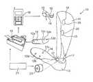
- a bracehaving an upper portion provided with a plurality of electrodes, a lower portion pivotally connected to the upper portion, a controller, and a plurality of sensors operably connected to the controller.
- the controlleris operably connected to the plurality of electrodes to control the electrodes responsive to a signal from the controller.
- adjustable timing circuitryis provided. This circuitry overrides the stimulation circuitry through the sensors and provides intermittent recovery periods without stimulation to prevent onset of fatigue. During such recovery periods, the timing circuitry activates the joint solenoid so the joint in the ankle-foot orthosis becomes locked to provide passive resistance.
Landscapes
- Health & Medical Sciences (AREA)
- Life Sciences & Earth Sciences (AREA)
- Public Health (AREA)
- Veterinary Medicine (AREA)
- Animal Behavior & Ethology (AREA)
- General Health & Medical Sciences (AREA)
- Engineering & Computer Science (AREA)
- Biomedical Technology (AREA)
- Physical Education & Sports Medicine (AREA)
- Heart & Thoracic Surgery (AREA)
- Radiology & Medical Imaging (AREA)
- Pathology (AREA)
- Orthopedic Medicine & Surgery (AREA)
- Nuclear Medicine, Radiotherapy & Molecular Imaging (AREA)
- Nursing (AREA)
- Dentistry (AREA)
- Oral & Maxillofacial Surgery (AREA)
- Physics & Mathematics (AREA)
- Biophysics (AREA)
- Vascular Medicine (AREA)
- Medical Informatics (AREA)
- Molecular Biology (AREA)
- Surgery (AREA)
- Epidemiology (AREA)
- Pain & Pain Management (AREA)
- Rehabilitation Therapy (AREA)
- Rehabilitation Tools (AREA)
- Electrotherapy Devices (AREA)
Abstract
Description
Claims (19)
Priority Applications (1)
| Application Number | Priority Date | Filing Date | Title |
|---|---|---|---|
| US13/759,776US9456918B2 (en) | 2006-06-30 | 2013-02-05 | Orthosis and method of use for treatment and rehabilitation of dropfoot |
Applications Claiming Priority (4)
| Application Number | Priority Date | Filing Date | Title |
|---|---|---|---|
| US80636406P | 2006-06-30 | 2006-06-30 | |
| PCT/US2007/072535WO2008005865A1 (en) | 2006-06-30 | 2007-06-29 | Orthosis and method of use for treatment and rehabilitation of dropfoot |
| US30587810A | 2010-06-22 | 2010-06-22 | |
| US13/759,776US9456918B2 (en) | 2006-06-30 | 2013-02-05 | Orthosis and method of use for treatment and rehabilitation of dropfoot |
Related Parent Applications (3)
| Application Number | Title | Priority Date | Filing Date |
|---|---|---|---|
| PCT/US2007/072535DivisionWO2008005865A1 (en) | 2006-06-30 | 2007-06-29 | Orthosis and method of use for treatment and rehabilitation of dropfoot |
| US12/305,878DivisionUS8500668B2 (en) | 2006-06-30 | 2007-06-29 | Orthosis and method of use for treatment and rehabilitation of dropfoot |
| US30587810ADivision | 2006-06-30 | 2010-06-22 |
Publications (2)
| Publication Number | Publication Date |
|---|---|
| US20130165830A1 US20130165830A1 (en) | 2013-06-27 |
| US9456918B2true US9456918B2 (en) | 2016-10-04 |
Family
ID=38894901
Family Applications (2)
| Application Number | Title | Priority Date | Filing Date |
|---|---|---|---|
| US12/305,878Active2030-11-09US8500668B2 (en) | 2006-06-30 | 2007-06-29 | Orthosis and method of use for treatment and rehabilitation of dropfoot |
| US13/759,776Active - Reinstated2029-07-29US9456918B2 (en) | 2006-06-30 | 2013-02-05 | Orthosis and method of use for treatment and rehabilitation of dropfoot |
Family Applications Before (1)
| Application Number | Title | Priority Date | Filing Date |
|---|---|---|---|
| US12/305,878Active2030-11-09US8500668B2 (en) | 2006-06-30 | 2007-06-29 | Orthosis and method of use for treatment and rehabilitation of dropfoot |
Country Status (2)
| Country | Link |
|---|---|
| US (2) | US8500668B2 (en) |
| WO (1) | WO2008005865A1 (en) |
Cited By (4)
| Publication number | Priority date | Publication date | Assignee | Title |
|---|---|---|---|---|
| US20170333278A1 (en)* | 2016-05-19 | 2017-11-23 | Hyundai Motor Company | Wearable walkng assist robot and method for controlling the same |
| US20180028806A1 (en)* | 2016-07-29 | 2018-02-01 | Otto Bock Healthcare Gmbh | Orthosis |
| KR20210141018A (en)* | 2020-05-15 | 2021-11-23 | 인제대학교 산학협력단 | Food drop holder |
| US11654280B2 (en) | 2018-02-13 | 2023-05-23 | Ekso Bionics Holdings, Inc. | Structural integration and enhanced control of functional electrical stimulation in an exoskeleton device |
Families Citing this family (49)
| Publication number | Priority date | Publication date | Assignee | Title |
|---|---|---|---|---|
| US7899556B2 (en) | 2005-11-16 | 2011-03-01 | Bioness Neuromodulation Ltd. | Orthosis for a gait modulation system |
| US8972017B2 (en) | 2005-11-16 | 2015-03-03 | Bioness Neuromodulation Ltd. | Gait modulation system and method |
| EP2586489B1 (en) | 2006-05-01 | 2014-12-24 | Bioness Neuromodulation Ltd | Improved functional electrical stimulation systems |
| WO2008066856A2 (en)* | 2006-11-27 | 2008-06-05 | Northeastern University | Patient specific ankle-foot orthotic device |
| US20090043357A1 (en)* | 2007-08-07 | 2009-02-12 | The Hong Kong Polytechnic University | Wireless real-time feedback control functional electrical stimulation system |
| DE102009030217A1 (en) | 2009-06-23 | 2011-01-05 | Otto Bock Healthcare Products Gmbh | Method for setting up a controller and orthopedic device |
| KR101709605B1 (en)* | 2009-07-01 | 2017-02-23 | 렉스 바이오닉스 리미티드 | Control system for a mobility aid |
| GB2474239B (en)* | 2009-10-06 | 2011-10-19 | Salisbury Nhs Foundation Trust | Apparatus for electrical stimulation of the body |
| US20110137375A1 (en)* | 2009-12-03 | 2011-06-09 | Mcbride Keith | System and method for detection of inversion and eversion of the foot using a multi-chamber insole |
| EP2512591A4 (en)* | 2009-12-15 | 2013-09-18 | Neurodan As | A system for electrical stimulation of nerves |
| WO2012050908A2 (en)* | 2010-09-28 | 2012-04-19 | Orthocare Innovations Llc | Computerized orthotic prescription system |
| US9011346B2 (en) | 2011-01-27 | 2015-04-21 | The Board Of Trustees Of The Leland Stanford Junior University | Systems and methods for monitoring the circulatory system |
| US20140094873A1 (en)* | 2011-05-17 | 2014-04-03 | Nordic Neurostim Aps | Footwear product for functional electrical stimulation |
| GB2493904B (en) | 2011-08-12 | 2014-03-19 | Actegy Ltd | Apparatus for providing electrical stimulation to a subject |
| US8560077B2 (en) | 2011-10-04 | 2013-10-15 | Feinstein Patents Llc | Universal musculoskeletal rehab device (brace, sleeve, or pad) for electrical treatment modalities and biofeedback response monitoring |
| WO2014089331A1 (en) | 2012-12-06 | 2014-06-12 | Ossur Hf | Electrical stimulation for orthopedic devices |
| US9867985B2 (en) | 2014-03-24 | 2018-01-16 | Bioness Inc. | Systems and apparatus for gait modulation and methods of use |
| US9943241B2 (en) | 2014-06-12 | 2018-04-17 | PhysioWave, Inc. | Impedance measurement devices, systems, and methods |
| US9546898B2 (en) | 2014-06-12 | 2017-01-17 | PhysioWave, Inc. | Fitness testing scale |
| US10130273B2 (en) | 2014-06-12 | 2018-11-20 | PhysioWave, Inc. | Device and method having automatic user-responsive and user-specific physiological-meter platform |
| US9568354B2 (en) | 2014-06-12 | 2017-02-14 | PhysioWave, Inc. | Multifunction scale with large-area display |
| US9949662B2 (en) | 2014-06-12 | 2018-04-24 | PhysioWave, Inc. | Device and method having automatic user recognition and obtaining impedance-measurement signals |
| US9693696B2 (en) | 2014-08-07 | 2017-07-04 | PhysioWave, Inc. | System with user-physiological data updates |
| US10500081B2 (en) | 2015-06-12 | 2019-12-10 | Becker Orthopedic Appliance Company | Triple action orthotic ankle joint and methods |
| US11395753B2 (en) | 2015-06-12 | 2022-07-26 | Becker Orthopedic Appliance Company | Orthotic joint devices, joint device components, and methods |
| US10945671B2 (en) | 2015-06-23 | 2021-03-16 | PhysioWave, Inc. | Determining physiological parameters using movement detection |
| US10436630B2 (en) | 2015-11-20 | 2019-10-08 | PhysioWave, Inc. | Scale-based user-physiological data hierarchy service apparatuses and methods |
| US10923217B2 (en) | 2015-11-20 | 2021-02-16 | PhysioWave, Inc. | Condition or treatment assessment methods and platform apparatuses |
| US10395055B2 (en) | 2015-11-20 | 2019-08-27 | PhysioWave, Inc. | Scale-based data access control methods and apparatuses |
| US10553306B2 (en) | 2015-11-20 | 2020-02-04 | PhysioWave, Inc. | Scaled-based methods and apparatuses for automatically updating patient profiles |
| US11561126B2 (en) | 2015-11-20 | 2023-01-24 | PhysioWave, Inc. | Scale-based user-physiological heuristic systems |
| US10980483B2 (en) | 2015-11-20 | 2021-04-20 | PhysioWave, Inc. | Remote physiologic parameter determination methods and platform apparatuses |
| WO2017123608A1 (en) | 2016-01-11 | 2017-07-20 | Bioness Inc. | Systems and apparatus for gait modulation and methods of use |
| US10390772B1 (en) | 2016-05-04 | 2019-08-27 | PhysioWave, Inc. | Scale-based on-demand care system |
| US10215619B1 (en) | 2016-09-06 | 2019-02-26 | PhysioWave, Inc. | Scale-based time synchrony |
| EP3525729B1 (en)* | 2016-10-13 | 2023-08-02 | Dephy, Inc. | Unidirectional actuated exoskeleton device |
| KR102349103B1 (en) | 2016-11-09 | 2022-01-07 | 한국로봇융합연구원 | Ankle rehabilitation apparatus for neurological disease |
| US10874539B2 (en) | 2017-05-05 | 2020-12-29 | Becker Orthopedic Appliance Company | Configurable orthosis and method of definitive orthotic design, fabrication and validation |
| DE102017110762A1 (en)* | 2017-05-17 | 2018-11-22 | Ottobock Se & Co. Kgaa | Method for determining malpositions in the structure of a prosthesis |
| US11045381B2 (en)* | 2017-07-20 | 2021-06-29 | Bose Corporation | Augmenting human motion |
| EP3492049A1 (en)* | 2017-11-09 | 2019-06-05 | Michael Natsis | Support tray arrangement |
| USD866788S1 (en)* | 2018-06-14 | 2019-11-12 | Shenzhen Fit King Health Tech. Co., Ltd | Leg massager |
| USD866787S1 (en)* | 2018-06-14 | 2019-11-12 | Shenzhen Fit King Health Tech. Co., Ltd | Leg massager |
| KR102550854B1 (en) | 2018-12-13 | 2023-07-04 | 삼성전자주식회사 | Method and device for assisting walking |
| CN113924069B (en) | 2019-04-08 | 2024-12-13 | Lb2科技有限公司 | Lower limb orthosis |
| DE102019210103A1 (en)* | 2019-07-09 | 2021-01-14 | Dindia Gutmann | Portable device and method for mobilizing a person with a neurologically caused walking disorder as a result of impaired proprioception and a carrying aid for such a device |
| US12318610B1 (en) | 2019-10-18 | 2025-06-03 | Enlighten Mobility Llc | Gait trainer with neuromodulation integration |
| CN111407428B (en)* | 2020-03-30 | 2021-02-26 | 山东大学齐鲁医院(青岛) | Tibiofibular joint stability detector under jaw type |
| US12186220B1 (en)* | 2024-06-21 | 2025-01-07 | Joseph B Sia | Stimulating foot brace |
Citations (12)
| Publication number | Priority date | Publication date | Assignee | Title |
|---|---|---|---|---|
| US5112296A (en) | 1991-04-30 | 1992-05-12 | The Board Of Supervisors Of Louisiana State University | Biofeedback activated orthosis for foot-drop rehabilitation |
| US5121747A (en) | 1985-11-06 | 1992-06-16 | University Of Strathclyde | Hybrid orthosis |
| US5306230A (en) | 1992-09-23 | 1994-04-26 | Rob Bodine/Capra Research | Knee extending orthotic appliance |
| US5476441A (en) | 1993-09-30 | 1995-12-19 | Massachusetts Institute Of Technology | Controlled-brake orthosis |
| US5643332A (en) | 1995-09-20 | 1997-07-01 | Neuromotion Inc. | Assembly for functional electrical stimulation during movement |
| US5748845A (en) | 1995-07-31 | 1998-05-05 | Motorola, Inc. | FES method and system for controlling the movement of a limb |
| US6377178B1 (en) | 2000-06-20 | 2002-04-23 | William DeToro | Therapeutic ankle & foot apparatus having a contact sensor mechanism |
| US6507757B1 (en)* | 2000-06-20 | 2003-01-14 | Ian Douglas Swain | Apparatus for electrical stimulation of the body |
| US6602217B2 (en) | 2001-10-16 | 2003-08-05 | Ck Partners, Llc | Foot drop assistance device |
| US6676618B2 (en) | 2000-03-14 | 2004-01-13 | Henrik Spang Andersen | Ankle-foot orthosis and a method for making the same |
| US20050070834A1 (en) | 2003-09-25 | 2005-03-31 | Massachusetts Institute Of Technology | Active Ankle Foot Orthosis |
| US6926687B2 (en) | 2003-09-26 | 2005-08-09 | Daniel J. Shields | Ankle-foot orthosis |
- 2007
- 2007-06-29USUS12/305,878patent/US8500668B2/enactiveActive
- 2007-06-29WOPCT/US2007/072535patent/WO2008005865A1/enactiveApplication Filing
- 2013
- 2013-02-05USUS13/759,776patent/US9456918B2/enactiveActive - Reinstated
Patent Citations (13)
| Publication number | Priority date | Publication date | Assignee | Title |
|---|---|---|---|---|
| US5121747A (en) | 1985-11-06 | 1992-06-16 | University Of Strathclyde | Hybrid orthosis |
| US5112296A (en) | 1991-04-30 | 1992-05-12 | The Board Of Supervisors Of Louisiana State University | Biofeedback activated orthosis for foot-drop rehabilitation |
| US5306230A (en) | 1992-09-23 | 1994-04-26 | Rob Bodine/Capra Research | Knee extending orthotic appliance |
| US5476441A (en) | 1993-09-30 | 1995-12-19 | Massachusetts Institute Of Technology | Controlled-brake orthosis |
| US5748845A (en) | 1995-07-31 | 1998-05-05 | Motorola, Inc. | FES method and system for controlling the movement of a limb |
| US5814093A (en) | 1995-09-20 | 1998-09-29 | Neuromotion Inc. | Assembly for functional electrical stimulation during movement |
| US5643332A (en) | 1995-09-20 | 1997-07-01 | Neuromotion Inc. | Assembly for functional electrical stimulation during movement |
| US6676618B2 (en) | 2000-03-14 | 2004-01-13 | Henrik Spang Andersen | Ankle-foot orthosis and a method for making the same |
| US6377178B1 (en) | 2000-06-20 | 2002-04-23 | William DeToro | Therapeutic ankle & foot apparatus having a contact sensor mechanism |
| US6507757B1 (en)* | 2000-06-20 | 2003-01-14 | Ian Douglas Swain | Apparatus for electrical stimulation of the body |
| US6602217B2 (en) | 2001-10-16 | 2003-08-05 | Ck Partners, Llc | Foot drop assistance device |
| US20050070834A1 (en) | 2003-09-25 | 2005-03-31 | Massachusetts Institute Of Technology | Active Ankle Foot Orthosis |
| US6926687B2 (en) | 2003-09-26 | 2005-08-09 | Daniel J. Shields | Ankle-foot orthosis |
Non-Patent Citations (2)
| Title |
|---|
| Kern, H., et al.; Denervated muscles in humans: limitations and problems of currently used functional electrical stimulation training protocols; Artificial Organs; Apr. 4, 2002; 26(3); 216-218. |
| LaMontagne, E., et al.; "Let's Walk" Ankle Foot Orthotic Development; College of Engineering, Drexel University; Mar. 26, 2007; pp. 1-21; Retrieved from Drexel E-Repository and Archive (IDEA) http://idea.library.drexel.edu/. |
Cited By (7)
| Publication number | Priority date | Publication date | Assignee | Title |
|---|---|---|---|---|
| US20170333278A1 (en)* | 2016-05-19 | 2017-11-23 | Hyundai Motor Company | Wearable walkng assist robot and method for controlling the same |
| US10765583B2 (en)* | 2016-05-19 | 2020-09-08 | Hyundai Motor Company | Wearable walking assist robot and method for controlling the same |
| US11944580B2 (en) | 2016-05-19 | 2024-04-02 | Hyundai Motor Company | Wearable walking assist robot and method for controlling the same |
| US20180028806A1 (en)* | 2016-07-29 | 2018-02-01 | Otto Bock Healthcare Gmbh | Orthosis |
| US11654280B2 (en) | 2018-02-13 | 2023-05-23 | Ekso Bionics Holdings, Inc. | Structural integration and enhanced control of functional electrical stimulation in an exoskeleton device |
| US12324914B2 (en) | 2018-02-13 | 2025-06-10 | Ekso Bionics Holdings, Inc. | Structural integration and enhanced control of functional electrical stimulation in an exoskeleton device |
| KR20210141018A (en)* | 2020-05-15 | 2021-11-23 | 인제대학교 산학협력단 | Food drop holder |
Also Published As
| Publication number | Publication date |
|---|---|
| US20130165830A1 (en) | 2013-06-27 |
| US20100262044A1 (en) | 2010-10-14 |
| US8500668B2 (en) | 2013-08-06 |
| WO2008005865A1 (en) | 2008-01-10 |
Similar Documents
| Publication | Publication Date | Title |
|---|---|---|
| US9456918B2 (en) | Orthosis and method of use for treatment and rehabilitation of dropfoot | |
| CN106659892B (en) | Systems and methods for functional electrical stimulation | |
| US8452410B2 (en) | Method and device for reflex-based functional gait training | |
| US11672983B2 (en) | Sensor in clothing of limbs or footwear | |
| US20040122483A1 (en) | Neuroprosthesis system for improved lower-limb function | |
| US8892213B2 (en) | Orthotic feedback system | |
| KR100946186B1 (en) | Robot Orthosis Of Not | |
| US20070203435A1 (en) | System And Method For Gait Synchronized Vibratory Stimulation Of The Feet | |
| US20060085047A1 (en) | Neuromuscular electrical stimulation of the foot muscles for prevention of deep vein thrombosis and pulmonary embolism with motion detection control | |
| US20180126158A1 (en) | Systems and Methods for Functional Restoration and Rehabilitation of Posture, Gait and Movement | |
| CN111167010A (en) | Control system for motion reconstruction and/or recovery of patients | |
| US11580877B2 (en) | Movement reconstruction control system | |
| EP2485803B1 (en) | Apparatus for functional electrical stimulation of the body | |
| US9480300B2 (en) | Orthotic device | |
| US20250134761A1 (en) | Muscle passive haptic rehabilitation systems and methods for treating neurological dysfunctions | |
| CN215131154U (en) | Correcting shoe combining ankle-foot orthosis with functional electrical stimulation | |
| Waters et al. | Lower Extremity Management of Hemiparesis. | |
| HK40082656A (en) | Gait event-driven, phase-dependent and multi-modal foot rehabilitation system and use method thereof | |
| JP2006006916A (en) | Walking aid for hemiplegia patient | |
| KR101143722B1 (en) | Gait assistance device for a hemiplegia | |
| HK1235725A1 (en) | System and method for functional electrical stimulation | |
| HK1235725B (en) | System and method for functional electrical stimulation |
Legal Events
| Date | Code | Title | Description |
|---|---|---|---|
| ZAAA | Notice of allowance and fees due | Free format text:ORIGINAL CODE: NOA | |
| ZAAB | Notice of allowance mailed | Free format text:ORIGINAL CODE: MN/=. | |
| STCF | Information on status: patent grant | Free format text:PATENTED CASE | |
| FEPP | Fee payment procedure | Free format text:MAINTENANCE FEE REMINDER MAILED (ORIGINAL EVENT CODE: REM.); ENTITY STATUS OF PATENT OWNER: SMALL ENTITY | |
| FEPP | Fee payment procedure | Free format text:SURCHARGE FOR LATE PAYMENT, SMALL ENTITY (ORIGINAL EVENT CODE: M2554); ENTITY STATUS OF PATENT OWNER: SMALL ENTITY | |
| MAFP | Maintenance fee payment | Free format text:PAYMENT OF MAINTENANCE FEE, 4TH YR, SMALL ENTITY (ORIGINAL EVENT CODE: M2551); ENTITY STATUS OF PATENT OWNER: SMALL ENTITY Year of fee payment:4 | |
| FEPP | Fee payment procedure | Free format text:MAINTENANCE FEE REMINDER MAILED (ORIGINAL EVENT CODE: REM.); ENTITY STATUS OF PATENT OWNER: SMALL ENTITY | |
| LAPS | Lapse for failure to pay maintenance fees | Free format text:PATENT EXPIRED FOR FAILURE TO PAY MAINTENANCE FEES (ORIGINAL EVENT CODE: EXP.); ENTITY STATUS OF PATENT OWNER: SMALL ENTITY | |
| STCH | Information on status: patent discontinuation | Free format text:PATENT EXPIRED DUE TO NONPAYMENT OF MAINTENANCE FEES UNDER 37 CFR 1.362 | |
| PRDP | Patent reinstated due to the acceptance of a late maintenance fee | Effective date:20241126 | |
| FEPP | Fee payment procedure | Free format text:PETITION RELATED TO MAINTENANCE FEES FILED (ORIGINAL EVENT CODE: PMFP); ENTITY STATUS OF PATENT OWNER: SMALL ENTITY Free format text:PETITION RELATED TO MAINTENANCE FEES GRANTED (ORIGINAL EVENT CODE: PMFG); ENTITY STATUS OF PATENT OWNER: SMALL ENTITY Free format text:SURCHARGE, PETITION TO ACCEPT PYMT AFTER EXP, UNINTENTIONAL. (ORIGINAL EVENT CODE: M2558); ENTITY STATUS OF PATENT OWNER: SMALL ENTITY | |
| MAFP | Maintenance fee payment | Free format text:PAYMENT OF MAINTENANCE FEE, 8TH YR, SMALL ENTITY (ORIGINAL EVENT CODE: M2552); ENTITY STATUS OF PATENT OWNER: SMALL ENTITY Year of fee payment:8 | |
| STCF | Information on status: patent grant | Free format text:PATENTED CASE | |
| FP | Lapsed due to failure to pay maintenance fee | Effective date:20241004 |