US9456904B2 - Facet fixation device - Google Patents
Facet fixation deviceDownload PDFInfo
- Publication number
- US9456904B2 US9456904B2US14/061,570US201314061570AUS9456904B2US 9456904 B2US9456904 B2US 9456904B2US 201314061570 AUS201314061570 AUS 201314061570AUS 9456904 B2US9456904 B2US 9456904B2
- Authority
- US
- United States
- Prior art keywords
- shaped body
- elongated component
- implant assembly
- implant
- assembly
- Prior art date
- Legal status (The legal status is an assumption and is not a legal conclusion. Google has not performed a legal analysis and makes no representation as to the accuracy of the status listed.)
- Active, expires
Links
Images


Classifications
- A—HUMAN NECESSITIES
- A61—MEDICAL OR VETERINARY SCIENCE; HYGIENE
- A61F—FILTERS IMPLANTABLE INTO BLOOD VESSELS; PROSTHESES; DEVICES PROVIDING PATENCY TO, OR PREVENTING COLLAPSING OF, TUBULAR STRUCTURES OF THE BODY, e.g. STENTS; ORTHOPAEDIC, NURSING OR CONTRACEPTIVE DEVICES; FOMENTATION; TREATMENT OR PROTECTION OF EYES OR EARS; BANDAGES, DRESSINGS OR ABSORBENT PADS; FIRST-AID KITS
- A61F2/00—Filters implantable into blood vessels; Prostheses, i.e. artificial substitutes or replacements for parts of the body; Appliances for connecting them with the body; Devices providing patency to, or preventing collapsing of, tubular structures of the body, e.g. stents
- A61F2/02—Prostheses implantable into the body
- A61F2/30—Joints
- A61F2/44—Joints for the spine, e.g. vertebrae, spinal discs
- A61F2/4455—Joints for the spine, e.g. vertebrae, spinal discs for the fusion of spinal bodies, e.g. intervertebral fusion of adjacent spinal bodies, e.g. fusion cages
- A—HUMAN NECESSITIES
- A61—MEDICAL OR VETERINARY SCIENCE; HYGIENE
- A61B—DIAGNOSIS; SURGERY; IDENTIFICATION
- A61B17/00—Surgical instruments, devices or methods
- A61B17/56—Surgical instruments or methods for treatment of bones or joints; Devices specially adapted therefor
- A61B17/58—Surgical instruments or methods for treatment of bones or joints; Devices specially adapted therefor for osteosynthesis, e.g. bone plates, screws or setting implements
- A61B17/68—Internal fixation devices, including fasteners and spinal fixators, even if a part thereof projects from the skin
- A61B17/70—Spinal positioners or stabilisers, e.g. stabilisers comprising fluid filler in an implant
- A61B17/7062—Devices acting on, attached to, or simulating the effect of, vertebral processes, vertebral facets or ribs ; Tools for such devices
- A61B17/7064—Devices acting on, attached to, or simulating the effect of, vertebral facets; Tools therefor
Definitions
- the human lumbar spineincludes individual vertebras that are connected to each other via a three joint complex—the vertebral disc and two facet joints. Under normal circumstances these structures function to protect the neural structures and to allow us to stand erect, bear axial loads, and be flexible for bending and rotation. When disorders of the spine occur due to disease or trauma, one or more of these spinal structures may function abnormally resulting in pain. In these pathologic circumstances, surgery may be required to stabilize the spine, protect the neural structures, and to relieve patient discomfort.
- posterior stabilization rods and pedicle screwsin combination with the insertion of an intervertebral implant is an effective method of spinal fusion.
- the operating procedure for implanting pedicle screws and rodsis very invasive, and can result in many different postoperative problems. Accordingly, it is desirable to provide alternatives to pedicle screws and rods that provide stabilization to augment the intervertebral procedure.
- the inventionfeatures an implant assembly for stabilization of a facet joint including an implant having a U-shaped body.
- the U-shaped bodycomprises a rounded front end, an open back end, first and second elongated components extending from the rounded front end, forming the U-shaped body and ending at the open back end and a helical structure extending within the U-shaped body that serves as a locking mechanism.
- FIG. 1Ashows a perspective view of an implant assembly in accordance of an embodiment of the invention
- FIG. 1Bshows a side view of an implant assembly in accordance of an embodiment of the invention
- FIG. 1Cshows a side view of an implant assembly in accordance of an embodiment of the invention
- FIG. 1Dshows a top view of an implant assembly in accordance of an embodiment of the invention
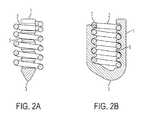
- FIGS. 2A and 2Bshow a cross-section view of an implant assembly in accordance of an embodiment of the invention.
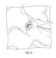
- FIGS. 3 and 4show the placement of an implant assembly in a facet joint in accordance with an embodiment of the invention.
- An embodiment of the inventionis directed to an implant assembly for stabilization of a spinal facet joint including an implant having a U-shaped body wherein the U-shaped body comprises a rounded front end, an open back end, first and second elongated components extending from the rounded front end, forming the U-shaped body and ending at the open back end and a helical structure extending within the U-shaped body that serves as a locking mechanism.
- the U-shaped bodycomprises a rounded front end, an open back end, first and second elongated components extending from the rounded front end, forming the U-shaped body and ending at the open back end and a helical structure extending within the U-shaped body that serves as a locking mechanism.
- grooves or threadsare introduced in the first and second elongated components.
- the helical structurelocks the U-shaped body in place within a joint.
- the insertion of the U-shaped bodygenerally distracts the facet joint.
- Biologically active materials meant to promote fusioni.e. stem cells, bone void filler, etc. can be inserted into the space created by the insertion of the implant assembly.
- the assemblycomprises bilateral placement of two sets of implants. In certain aspects of the invention, the assembly is used in conjunction with an intervertebral implant.
- An embodiment of the inventionallows the soft tissues in the facet joint to be removed and the facet joint to be treated with stem cells, synthetic bone substitute, BMP or any other biologically active substance which promotes fusion. This is enabled by a U-shaped body.
- the U-shaped bodywhen placed in the joint space, expands the joint space and creates the necessary space to remove the native soft tissues.
- grooves and/or threadsare introduced in the first and second elongated components to secure the implant in place.
- a helical structurein place of grooves or threads in the first and second elongated components, is introduced into the open part of the U-shaped body.
- the helical structureanchors the U-shaped body to the bone.
- the U-shaped body/spaceris open on one end. This allows the surgeon to work on the joint space after the spacer is placed and with the joint distracted. This extra space will allow the surgeon to used reamers, rasps, drills, rongures, files, etc. to remove more soft tissue from the joint.
- the ability to remove residual soft tissue from joints being fusedis advantageous because these tissues can lead to non-unions and pseudoarthrosis.
- the surgeonimplants the helical anchor which locks the spacer in place to prevent migration. This is accomplished while minimizing the volume of the anchor by using a helical shape instead of a fenestrated screw.
- the helical anchoris self-locking as the final turn is made
- biologically active materials meant to promote fusioni.e. stem cells, bone void filler, etc.
- biologically active materials meant to promote fusioncan be inserted into the space within the helical anchor. Contact between the inserted material and native bone is maximized by the helical nature of the anchor, because of its low volume and open structure.
- An embodiment of the inventionis directed to a lumbar facet fixation device intended to be used in conjunction with an anterior fusion.
- the facet fixation device describedshould provide supplementation stabilization to the spine while a biological fusion matures in the interbody space and the two associated facet joints at that level.
- the deviceis installed in such a way that the facet joint is easily prepared to accept a biologically active material that will promote bone fusion in the joint.
- the devicehas a largely open structure relative to the bone proximate the facet joint which will allow for a relatively large volume of biologically active material to be placed and for the resultant mature bone fusion mass to be well connected to the native tissues.
- the implant assemblyis comprised of two components: a U-shaped spacer and a helical bone anchor.
- FIGS. 1A to 1D and FIGS. 2A to 2Bshow standard and isometric views of the implant assembly of the claimed invention.
- the implant assembly 10comprising a U-shaped spacer 1 is shown.
- the U-shaped spacer 1is not necessarily symmetric about any plane.
- one arm 1 ais longer than the other 1 b .
- the bottom of the U-shaped spacer 3is angled.
- the purpose of the variation in sizes of the arms of the spacer and the angled shaped of the bottom of the spaceris to allow the U-shaped spacer to accommodate the shape of the facet joint in which it is inserted, and the several shapes and sizes that would be necessary to accommodate various patient anatomy and spinal levels.
- a helical anchor 2is inserted into the U-shaped spacer 1 .
- the helical anchor 2is similar in shape to a compression spring.
- the arms of the U-shaped spacercomprise grooves 4 on both faces of the arms as shown in FIG. 1A . The grooves 4 increase friction between the spacer 1 and the bone when the implant assembly 10 is placed within a joint of a subject (as shown in FIGS. 3 and 4 ).
- the U-shaped spacer 1comprises indentations 5 , which are shaped to accommodate the helical anchor 5 .
- the indentations 5interact with the helical anchor 2 and accommodate the portions of the helical anchor that contact the inner face of the U-shaped spacer 1 .
- the indentations 5are configured to position the helical anchor 2 within the U-shaped spacer. In other embodiments of the invention, the indentations 5 capture the helix at each of the indentations 5 .
- the leading edge 6 and trailing edge 7 of the helical anchor 2are shown in FIG. 1C .
- the pitch of the leading edge 6is unchanged.
- the leading edge 6is shaped into a point to facilitate the insertion of the implant assembly 10 into a joint.
- the trailing edge 7has a variable pitch. The purpose of the variable pitch for the trailing edge 7 is to provide a locking mechanism for the helical anchor 2 within the implant assembly 10 .
- the pitchis reduced, which causes the trailing edge 7 to snap into place where it contacts an arm of the U-shaped spacer 1 .
- the variable pitch feature of the trailing edge 7provides a surgeon with tactile feedback indicating that the anchor 2 is fully inserted into the spacer 1 .
- an internal space 2 ais formed within the helical anchor.
- the internal space 2 ais bounded by the helical anchor 2 and the sides and bottom of the U-shaped spacer 1 .
- the internal space 2 ais typically filled with biologically active material that is meant to promote fusion i.e. stem cells, bone void filler, etc.
- the outer edge 2 b of the helical anchorcontacts the bone within a joint and anchors the U-shaped spacer 1 to the bone and prevents the migration of the implant assembly 10 after it has been inserted into a facet joint.
- FIG. 2Ashows a representation of a cross-section 2 A- 2 A as set forth in FIG. 1B .
- FIG. 2Ashows the coils of the helical anchor 2 housed within the indentations 5 of the U-shaped spacer 1 .
- FIG. 2Bshows a representation of a cross-section 2 B- 2 B as set forth in FIG. 1C .
- FIG. 2Bshows the coils of the helical anchor 2 housed within the indentations 5 of the U-shaped spacer 1 and the locked position of the trailing edge 7 where it contacts an arm of the U-shaped spacer 1 .
- FIG. 3illustrates two assembled implants implanted bilaterally in the facet joint of the lumbar spine.
- FIG. 4shows a close-up view of one of implants from FIG. 3 .
- An embodiment of the inventionprovides a surgical procedure using the implant assembly of the claimed invention.
- a facet jointis targeted with a k-wire using the trajectory from an lateral to medial, superior to inferior approach such that the k-wire enters between the inferior articular surface of the superior vertebra and the superior articular process of the inferior vertebra.
- a series of dialatorsis used over the initial k-wire to split the muscle and blunt dissect to the facet joint. All but the largest dilator and the k-wire are removed.
- a cannulated drillis used to drill over the k-wire to the anterior aspect of the facet joint. The drill has an outer diameter that is slightly larger than the internal diameter of the helical anchor.
- a box chisselis used to prepare the joint for the spacer by making a rectangular cut slightly larger than the spacer into the joint.
- the U-Shape spacerin inserted in the correct orientation, usually angled bottom end ( 3 ) first, based on the shape of the facet and the shape of the implant. Trials may be used to determine the proper shape and height for the facet joint. The correct size will fill the joint and distract the joint to provide ligamentous tension on the spacer to stabilize the spine and spacer. Standard instruments are used to clear all tissues that remain in the joint inside the U-Shape of the spacer. Using a custom inserter, the helical anchor is inserted by rotating it into the U-shaped spacer until the end of the anchor snaps below either arm ( 1 a or 1 b ) of the spacer, preventing the anchor from reversing out of the bone.
- the space inside the U-shaped spacer and inside the helical anchoris filled with a biologically active material designed to promote bone fusion, or a combination of materials.
- a packing toolis used to compress the material and generate contact with the native bone.
- the implant constructcan be capped with a component designed to retain the material and prevent its movements while maturation occurs. This can be integrated into the helical anchor, spacer or a separate component. If necessary, the procedure can be repeated on another area of the spinal unit.
Landscapes
- Health & Medical Sciences (AREA)
- Orthopedic Medicine & Surgery (AREA)
- Neurology (AREA)
- Engineering & Computer Science (AREA)
- Biomedical Technology (AREA)
- Life Sciences & Earth Sciences (AREA)
- Surgery (AREA)
- General Health & Medical Sciences (AREA)
- Veterinary Medicine (AREA)
- Heart & Thoracic Surgery (AREA)
- Public Health (AREA)
- Animal Behavior & Ethology (AREA)
- Molecular Biology (AREA)
- Medical Informatics (AREA)
- Nuclear Medicine, Radiotherapy & Molecular Imaging (AREA)
- Cardiology (AREA)
- Oral & Maxillofacial Surgery (AREA)
- Transplantation (AREA)
- Vascular Medicine (AREA)
- Prostheses (AREA)
- Surgical Instruments (AREA)
Abstract
Description
Claims (17)
Priority Applications (1)
| Application Number | Priority Date | Filing Date | Title |
|---|---|---|---|
| US14/061,570US9456904B2 (en) | 2012-10-23 | 2013-10-23 | Facet fixation device |
Applications Claiming Priority (2)
| Application Number | Priority Date | Filing Date | Title |
|---|---|---|---|
| US201261717513P | 2012-10-23 | 2012-10-23 | |
| US14/061,570US9456904B2 (en) | 2012-10-23 | 2013-10-23 | Facet fixation device |
Publications (2)
| Publication Number | Publication Date |
|---|---|
| US20140114418A1 US20140114418A1 (en) | 2014-04-24 |
| US9456904B2true US9456904B2 (en) | 2016-10-04 |
Family
ID=50486041
Family Applications (1)
| Application Number | Title | Priority Date | Filing Date |
|---|---|---|---|
| US14/061,570Active2034-01-21US9456904B2 (en) | 2012-10-23 | 2013-10-23 | Facet fixation device |
Country Status (1)
| Country | Link |
|---|---|
| US (1) | US9456904B2 (en) |
Cited By (2)
| Publication number | Priority date | Publication date | Assignee | Title |
|---|---|---|---|---|
| US20170156879A1 (en)* | 2015-12-02 | 2017-06-08 | Brian Patrick Janowski | Helical lock spacer, instruments and methods |
| US20190090922A1 (en)* | 2017-09-22 | 2019-03-28 | Howmedica Osteonics Corp. | Distal Radius Wedge Screw |
Families Citing this family (10)
| Publication number | Priority date | Publication date | Assignee | Title |
|---|---|---|---|---|
| WO2013059763A1 (en)* | 2011-10-21 | 2013-04-25 | Custom Spine, Inc. | Facet screw system and method |
| US10492921B2 (en) | 2015-04-29 | 2019-12-03 | Institute for Musculoskeletal Science and Education, Ltd. | Implant with arched bone contacting elements |
| US10449051B2 (en)* | 2015-04-29 | 2019-10-22 | Institute for Musculoskeletal Science and Education, Ltd. | Implant with curved bone contacting elements |
| JP6768001B2 (en) | 2015-04-29 | 2020-10-14 | インスティテュート フォー マスキュロスケレタル サイエンス アンド エジュケイション,リミテッド | Coiled implants and systems and how to make them |
| US10478312B2 (en) | 2016-10-25 | 2019-11-19 | Institute for Musculoskeletal Science and Education, Ltd. | Implant with protected fusion zones |
| US11033394B2 (en) | 2016-10-25 | 2021-06-15 | Institute for Musculoskeletal Science and Education, Ltd. | Implant with multi-layer bone interfacing lattice |
| US10512549B2 (en) | 2017-03-13 | 2019-12-24 | Institute for Musculoskeletal Science and Education, Ltd. | Implant with structural members arranged around a ring |
| US10940015B2 (en) | 2017-11-21 | 2021-03-09 | Institute for Musculoskeletal Science and Education, Ltd. | Implant with improved flow characteristics |
| US10744001B2 (en) | 2017-11-21 | 2020-08-18 | Institute for Musculoskeletal Science and Education, Ltd. | Implant with improved bone contact |
| FR3132625B1 (en)* | 2022-02-17 | 2024-04-12 | Sc Medica | IMPLANT DEVICE FOR PERFORMING A POSTERIOR SPINAL ARTHRODESIS AT THE LEVEL OF A FACET JOINT, AND SYSTEM COMPRISING SAID IMPLANT AND ITS PLACEMENT TOOL. |
Citations (9)
| Publication number | Priority date | Publication date | Assignee | Title |
|---|---|---|---|---|
| US20040082953A1 (en)* | 2000-07-31 | 2004-04-29 | Dominique Petit | Cage for immobilization of the spine and for osteosynthesis, method of manufacturing a cage, method of implanting a cage, and method of removing a cage |
| US6824564B2 (en)* | 1997-04-25 | 2004-11-30 | Stryker France, Sas | Two-part intersomatic implant |
| US20050143733A1 (en)* | 2002-02-11 | 2005-06-30 | Dominique Petit | System for fixing a part to a bone element |
| US7291170B2 (en)* | 2000-05-18 | 2007-11-06 | Ldr Medical | Intersomatic cage with unified grafts |
| US20080255666A1 (en)* | 2007-04-13 | 2008-10-16 | Depuy Spine, Inc. | Facet fixation and fusion wedge and method of use |
| US20090306671A1 (en)* | 2008-06-06 | 2009-12-10 | Providence Medical Technology, Inc. | Facet joint implants and delivery tools |
| US20100331895A1 (en)* | 2005-08-15 | 2010-12-30 | Berend Linke | Osteosynthetic device |
| US20110166660A1 (en)* | 2008-09-02 | 2011-07-07 | Synthes Usa, Llc | Implant with spiral anchor |
| US8900310B2 (en)* | 2012-04-05 | 2014-12-02 | Zimmer Spine, Inc. | Interbody spacer |
- 2013
- 2013-10-23USUS14/061,570patent/US9456904B2/enactiveActive
Patent Citations (9)
| Publication number | Priority date | Publication date | Assignee | Title |
|---|---|---|---|---|
| US6824564B2 (en)* | 1997-04-25 | 2004-11-30 | Stryker France, Sas | Two-part intersomatic implant |
| US7291170B2 (en)* | 2000-05-18 | 2007-11-06 | Ldr Medical | Intersomatic cage with unified grafts |
| US20040082953A1 (en)* | 2000-07-31 | 2004-04-29 | Dominique Petit | Cage for immobilization of the spine and for osteosynthesis, method of manufacturing a cage, method of implanting a cage, and method of removing a cage |
| US20050143733A1 (en)* | 2002-02-11 | 2005-06-30 | Dominique Petit | System for fixing a part to a bone element |
| US20100331895A1 (en)* | 2005-08-15 | 2010-12-30 | Berend Linke | Osteosynthetic device |
| US20080255666A1 (en)* | 2007-04-13 | 2008-10-16 | Depuy Spine, Inc. | Facet fixation and fusion wedge and method of use |
| US20090306671A1 (en)* | 2008-06-06 | 2009-12-10 | Providence Medical Technology, Inc. | Facet joint implants and delivery tools |
| US20110166660A1 (en)* | 2008-09-02 | 2011-07-07 | Synthes Usa, Llc | Implant with spiral anchor |
| US8900310B2 (en)* | 2012-04-05 | 2014-12-02 | Zimmer Spine, Inc. | Interbody spacer |
Cited By (4)
| Publication number | Priority date | Publication date | Assignee | Title |
|---|---|---|---|---|
| US20170156879A1 (en)* | 2015-12-02 | 2017-06-08 | Brian Patrick Janowski | Helical lock spacer, instruments and methods |
| US10166116B2 (en)* | 2015-12-02 | 2019-01-01 | Brian Patrick Janowski | Helical lock spacer, instruments and methods |
| US20190090922A1 (en)* | 2017-09-22 | 2019-03-28 | Howmedica Osteonics Corp. | Distal Radius Wedge Screw |
| US10828077B2 (en)* | 2017-09-22 | 2020-11-10 | Howmedica Osteonics Corp. | Distal radius wedge screw |
Also Published As
| Publication number | Publication date |
|---|---|
| US20140114418A1 (en) | 2014-04-24 |
Similar Documents
| Publication | Publication Date | Title |
|---|---|---|
| US9456904B2 (en) | Facet fixation device | |
| US11826084B2 (en) | System and method for bone fusing implants | |
| US10092329B2 (en) | Posterior functionally dynamic stabilization system | |
| US8460341B2 (en) | Dynamic facet replacement system | |
| US8241329B2 (en) | Device and method for the prevention of multi-level vertebral extension | |
| US20190105082A1 (en) | Systems and methods for posterior dynamic stabilization of the spine | |
| US8162981B2 (en) | Method and apparatus for spinal facet fusion | |
| US8002802B2 (en) | Devices and methods for inter-vertebral orthopedic device placement | |
| US7935136B2 (en) | Facet joint fusion devices and methods | |
| US8906092B2 (en) | Spinous process fixation devices and methods of use | |
| US9375239B2 (en) | Spinal fixation devices and methods of use | |
| US20090171394A1 (en) | Devices And Methods For The Treatment Of Facet Joint Disease | |
| US20100087923A1 (en) | Implants for facet joint repair and methods use | |
| US20060276790A1 (en) | Minimally invasive facet joint repair | |
| US20070288014A1 (en) | Spine treatment devices and methods | |
| US20080021466A1 (en) | Spine treatment devices and methods | |
| US20060293662A1 (en) | Spinous process spacer | |
| JP2012520131A (en) | Surgical tether device and method of use | |
| WO2009152256A2 (en) | Intraosseous transpedicular methods and devices | |
| US20080177333A1 (en) | Adjustable jacking implant | |
| WO2010127359A1 (en) | Method and apparatus for spinal interbody fusion | |
| AU2017281696B2 (en) | Method and apparatus for spinal facet fusion | |
| EP2629703A2 (en) | Method and apparatus for spinal facet fusion |
Legal Events
| Date | Code | Title | Description |
|---|---|---|---|
| AS | Assignment | Owner name:SPINESMITH PARTNERS, L.P., TEXAS Free format text:ASSIGNMENT OF ASSIGNORS INTEREST;ASSIGNORS:LANDRY, MICHAEL;DUNWORTH, KEVIN;REEL/FRAME:032405/0221 Effective date:20140304 | |
| AS | Assignment | Owner name:SILICON VALLEY BANK, CALIFORNIA Free format text:SECURITY INTEREST;ASSIGNOR:SPINESMITH HOLDINGS, LLC;REEL/FRAME:035014/0066 Effective date:20150110 | |
| STCF | Information on status: patent grant | Free format text:PATENTED CASE | |
| AS | Assignment | Owner name:BLUEARC MEZZANINE PARTNERS I, L.P., GEORGIA Free format text:SECURITY INTEREST;ASSIGNOR:SPINESMITH HOLDINGS, LLC;REEL/FRAME:042071/0370 Effective date:20170315 | |
| AS | Assignment | Owner name:AMERICAN BANK, N.A., TEXAS Free format text:SECURITY INTEREST;ASSIGNOR:SPINESMITH HOLDINGS, LLC;REEL/FRAME:044882/0096 Effective date:20171206 | |
| AS | Assignment | Owner name:BLUEARC MEZZANINE PARTNERS I, LP, GEORGIA Free format text:SECURITY INTEREST;ASSIGNOR:SPINESMITH HOLDINGS, LLC;REEL/FRAME:048839/0655 Effective date:20190329 | |
| AS | Assignment | Owner name:SPINESMITH HOLDINGS, LLC, TEXAS Free format text:RELEASE BY SECURED PARTY;ASSIGNOR:SILICON VALLEY BANK;REEL/FRAME:048853/0183 Effective date:20190408 | |
| MAFP | Maintenance fee payment | Free format text:PAYMENT OF MAINTENANCE FEE, 4TH YR, SMALL ENTITY (ORIGINAL EVENT CODE: M2551); ENTITY STATUS OF PATENT OWNER: SMALL ENTITY Year of fee payment:4 | |
| MAFP | Maintenance fee payment | Free format text:PAYMENT OF MAINTENANCE FEE, 8TH YR, SMALL ENTITY (ORIGINAL EVENT CODE: M2552); ENTITY STATUS OF PATENT OWNER: SMALL ENTITY Year of fee payment:8 |