US9456354B2 - Non-line of sight wireless communication system and method - Google Patents
Non-line of sight wireless communication system and methodDownload PDFInfo
- Publication number
- US9456354B2 US9456354B2US13/445,869US201213445869AUS9456354B2US 9456354 B2US9456354 B2US 9456354B2US 201213445869 AUS201213445869 AUS 201213445869AUS 9456354 B2US9456354 B2US 9456354B2
- Authority
- US
- United States
- Prior art keywords
- broadcast radio
- terminal
- link
- central
- radio
- Prior art date
- Legal status (The legal status is an assumption and is not a legal conclusion. Google has not performed a legal analysis and makes no representation as to the accuracy of the status listed.)
- Active, expires
Links
- 238000000034methodMethods0.000titleclaimsabstractdescription61
- 238000004891communicationMethods0.000titleclaimsdescription11
- 230000003044adaptive effectEffects0.000claimsdescription39
- 238000012545processingMethods0.000claimsdescription18
- 230000008569processEffects0.000claimsdescription8
- 238000003491arrayMethods0.000claimsdescription6
- 230000004931aggregating effectEffects0.000claimsdescription2
- 230000002452interceptive effectEffects0.000claimsdescription2
- 239000002131composite materialSubstances0.000claims1
- 238000000638solvent extractionMethods0.000claims1
- 239000013598vectorSubstances0.000description33
- 239000011159matrix materialSubstances0.000description29
- 230000010287polarizationEffects0.000description24
- 230000003595spectral effectEffects0.000description12
- 230000006870functionEffects0.000description9
- 230000001965increasing effectEffects0.000description7
- 230000009977dual effectEffects0.000description6
- 239000000203mixtureSubstances0.000description6
- 238000001228spectrumMethods0.000description6
- 230000005540biological transmissionEffects0.000description5
- 238000006880cross-coupling reactionMethods0.000description5
- 238000005516engineering processMethods0.000description4
- 238000009472formulationMethods0.000description4
- 239000000047productSubstances0.000description4
- 230000011664signalingEffects0.000description4
- 230000000694effectsEffects0.000description3
- 239000000945fillerSubstances0.000description3
- 230000014509gene expressionEffects0.000description3
- 238000005457optimizationMethods0.000description3
- 238000006467substitution reactionMethods0.000description3
- 230000008901benefitEffects0.000description2
- 230000015572biosynthetic processEffects0.000description2
- 230000015556catabolic processEffects0.000description2
- 238000006243chemical reactionMethods0.000description2
- 230000001186cumulative effectEffects0.000description2
- 238000000354decomposition reactionMethods0.000description2
- 238000005034decorationMethods0.000description2
- 238000006731degradation reactionMethods0.000description2
- 239000006185dispersionSubstances0.000description2
- 238000005562fadingMethods0.000description2
- 230000010076replicationEffects0.000description2
- 230000004044responseEffects0.000description2
- 230000002123temporal effectEffects0.000description2
- 238000012549trainingMethods0.000description2
- 101710195281Chlorophyll a-b binding proteinProteins0.000description1
- 101710143415Chlorophyll a-b binding protein 1, chloroplasticProteins0.000description1
- 101710181042Chlorophyll a-b binding protein 1A, chloroplasticProteins0.000description1
- 101710091905Chlorophyll a-b binding protein 2, chloroplasticProteins0.000description1
- 101710095244Chlorophyll a-b binding protein 3, chloroplasticProteins0.000description1
- 101710127489Chlorophyll a-b binding protein of LHCII type 1Proteins0.000description1
- 101710184917Chlorophyll a-b binding protein of LHCII type I, chloroplasticProteins0.000description1
- 101710102593Chlorophyll a-b binding protein, chloroplasticProteins0.000description1
- RYGMFSIKBFXOCR-UHFFFAOYSA-NCopperChemical compound[Cu]RYGMFSIKBFXOCR-UHFFFAOYSA-N0.000description1
- 238000003775Density Functional TheoryMethods0.000description1
- 241000196324EmbryophytaSpecies0.000description1
- 244000068988Glycine maxSpecies0.000description1
- 230000006978adaptationEffects0.000description1
- 238000013459approachMethods0.000description1
- 230000002457bidirectional effectEffects0.000description1
- 239000000969carrierSubstances0.000description1
- 230000001413cellular effectEffects0.000description1
- 230000001427coherent effectEffects0.000description1
- 229910052802copperInorganic materials0.000description1
- 239000010949copperSubstances0.000description1
- 238000012937correctionMethods0.000description1
- 125000004122cyclic groupChemical group0.000description1
- 230000007423decreaseEffects0.000description1
- 230000001934delayEffects0.000description1
- 230000003111delayed effectEffects0.000description1
- 230000001419dependent effectEffects0.000description1
- 238000005538encapsulationMethods0.000description1
- 230000002708enhancing effectEffects0.000description1
- 239000000835fiberSubstances0.000description1
- 230000001771impaired effectEffects0.000description1
- 230000006872improvementEffects0.000description1
- 238000007689inspectionMethods0.000description1
- 230000007246mechanismEffects0.000description1
- 230000000135prohibitive effectEffects0.000description1
- 230000009467reductionEffects0.000description1
- 230000035945sensitivityEffects0.000description1
- 238000000926separation methodMethods0.000description1
- 238000007493shaping processMethods0.000description1
- 239000013589supplementSubstances0.000description1
- 238000013509system migrationMethods0.000description1
- 230000009466transformationEffects0.000description1
- 230000001131transforming effectEffects0.000description1
- 238000004260weight controlMethods0.000description1
Images


Classifications
- H—ELECTRICITY
- H04—ELECTRIC COMMUNICATION TECHNIQUE
- H04W—WIRELESS COMMUNICATION NETWORKS
- H04W16/00—Network planning, e.g. coverage or traffic planning tools; Network deployment, e.g. resource partitioning or cells structures
- H04W16/24—Cell structures
- H04W16/28—Cell structures using beam steering
- H—ELECTRICITY
- H04—ELECTRIC COMMUNICATION TECHNIQUE
- H04B—TRANSMISSION
- H04B7/00—Radio transmission systems, i.e. using radiation field
- H04B7/02—Diversity systems; Multi-antenna system, i.e. transmission or reception using multiple antennas
- H04B7/04—Diversity systems; Multi-antenna system, i.e. transmission or reception using multiple antennas using two or more spaced independent antennas
- H04B7/06—Diversity systems; Multi-antenna system, i.e. transmission or reception using multiple antennas using two or more spaced independent antennas at the transmitting station
- H04B7/0613—Diversity systems; Multi-antenna system, i.e. transmission or reception using multiple antennas using two or more spaced independent antennas at the transmitting station using simultaneous transmission
- H04B7/0615—Diversity systems; Multi-antenna system, i.e. transmission or reception using multiple antennas using two or more spaced independent antennas at the transmitting station using simultaneous transmission of weighted versions of same signal
- H04B7/0617—Diversity systems; Multi-antenna system, i.e. transmission or reception using multiple antennas using two or more spaced independent antennas at the transmitting station using simultaneous transmission of weighted versions of same signal for beam forming
- H—ELECTRICITY
- H04—ELECTRIC COMMUNICATION TECHNIQUE
- H04B—TRANSMISSION
- H04B7/00—Radio transmission systems, i.e. using radiation field
- H04B7/02—Diversity systems; Multi-antenna system, i.e. transmission or reception using multiple antennas
- H04B7/10—Polarisation diversity; Directional diversity
- H—ELECTRICITY
- H04—ELECTRIC COMMUNICATION TECHNIQUE
- H04W—WIRELESS COMMUNICATION NETWORKS
- H04W24/00—Supervisory, monitoring or testing arrangements
- H04W24/02—Arrangements for optimising operational condition
- H—ELECTRICITY
- H04—ELECTRIC COMMUNICATION TECHNIQUE
- H04W—WIRELESS COMMUNICATION NETWORKS
- H04W52/00—Power management, e.g. Transmission Power Control [TPC] or power classes
- H04W52/04—Transmission power control [TPC]
- H04W52/38—TPC being performed in particular situations
- H04W52/42—TPC being performed in particular situations in systems with time, space, frequency or polarisation diversity
Definitions
- the disclosurerelates a wireless backhaul system that uses non-line of sight wireless communications and the non-line of sight wireless communications system and method.
- a backhaul systemis a communication system that is used to communicate certain data from a cellular network, for example, back to the central system in a communications system.
- Various different backhaul systemsare well known that are both wireless communication systems and wired communication systems.
- Most of the current wireless backhaul systemsare point to point (P2P) systems that operate in the licensed FDD (frequency division multiplexed or a frequency division protocol) microwave bands from 6 GHz to 80 GHz.
- P2Ppoint to point
- FDDfrequency division multiplexed or a frequency division protocol
- These systemsuse high gain parabolic dishes which must be manually pointed and also rely on the low sidelobe performance of the dish to reduce (but not eliminate) co-channel interference.
- these productsmust be used where line-of-sight is available.
- wireless carriersare migrating from a traditional macro-cellular network topology 10 to a micro-cellular and pico-cellular topologies 20 as shown in FIG. 1 . That is, instead of using a few high-high powered base-stations to cover large areas, they supplement these with many outdoor micro-cells and pico-cells as shown in FIG. 1 .
- the base station capacity(measured in Mbps) has been increasing slowly as operators migrate from 2.5G and 3G technologies (HSDPA, HSPA, CDMA 2000, CDMA EVO, etc) to 4G technologies (WiMax and LTE).
- 4G technologyincreases spectral efficiency only 50% relative to the previous generation.
- 4Gwill not solve the 10-fold increase needed to maintain a macro-cell topology while increasing user capacity.
- emerging wireless architecturessolve the throughput problem by increasing “capacity density” (measured in Mbps per km 2 ), and not by increasing capacity alone.
- micro- and pico-cellsIncreasing capacity density 10-fold can be solved by a dense deployment of micro- and pico-cells. Although these cells have limited range (100 to 500 meters), they retain the capacity similar to macro-cells, for the LTE standard 15 Mbps in 10 MHz of bandwidth and 39 Mbps in 10 MHz of bandwidth with 3-sectored implementations. Thus, a macro-cell with a range of 1 km (urban propagation) and capacity density of 15 Mbps/km 2 , evolves into a micro-cellular topology featuring a capacity density of 135 Mbps/km 2 using 9 micro-cells.
- FIG. 1illustrates a typical backhaul system migration from macro-cells
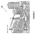
- FIG. 2illustrates an example of a non-line of sight system such as a non-line of sight, point to multipoint backhaul star architecture system;
- FIG. 3illustrates an example of an implementation of a wireless non-line of sight backhaul system
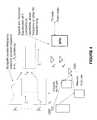
- FIG. 4illustrates details of the operation of the wireless non-line of sight backhaul system
- FIG. 5illustrates a method for multiplicative spectral efficiency in the non-line of sight system
- FIG. 6illustrates an example of an implementation of both concentrating backhaul radio and the terminating backhaul radios of the system
- FIG. 7illustrates an example of a 2-dimensional beamforming network subsystem
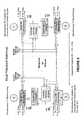
- FIG. 8illustrates an implementation of the communication protocol between the CBR and TBR of the system
- FIG. 9illustrates a set of uplink and downlink RF channels on the system.
- FIG. 10illustrates the RD channels.
- the disclosureis particularly applicable to a wireless non-line of sight backhaul system and method described below and it is in this context that the disclosure will be described. It will be appreciated, however, that the system and method has greater utility since the wireless non-line of sight backhaul system and method can be implemented in other manners that are within the scope of the disclosure.
- the systemis a wireless, non-line of sight backhaul system that enables self alignment and realignment of the antennas beams of the wireless radios of the system, that provides robust operation in licensed and unlicensed frequency bands, that facilitates the use of a reduced number of frequency channels from M to 1 and that enables operation in a non-line of sight (NLOS) propagation environment.
- the systemmay provide an increase in effective link spectral efficiency by using Extreme Interference Cancellation (EIC) and up to double the spectral efficiency by using two polarizations.
- EICExtreme Interference Cancellation
- the systemalso provides an improvement in link reliability by reducing fading.
- the systemalso cancels the radio interference to optimize signal to interference and noise ratio (SINR) and cancels interference from other self-generated co-channel interference.
- SINRsignal to interference and noise ratio
- the systemcan be operated in a line of sight, near line of sight and non-line of sight radio frequency (RF) propagation environments.
- the systemalso provides multi-target beam-forming that enhances spectral efficiency and can provided exceptional data concentration in small amounts of spectrum.
- the non-line of sight system described belowmay be use a single radio frequency channel to support the wireless backhaul requirements of a carrier. Now, an implementation of the system is described in more detail.
- FIG. 2illustrates an example of a non-line of sight system 30 such as a non-line of sight, point to multipoint backhaul star architecture system.
- the non-line of sight systemhas a star topology with a point-to-concentrating multipoint (P2CMP) connectivity that has two types of wireless nodes: concentrator backhaul radios (CBRs) and terminating backhaul radios (TBRs).
- the non-line of sight system 30may also have a point to point architecture, a multiple point to point architecture and a point to multipoint architecture.
- Each node in this wireless architecturemay be referenced simply as concentrator nodes (CN) and end nodes (EN) evocative of their positions in the network.
- CNconcentrator nodes
- ENend nodes
- Each concentrator nodeaggregates traffic from L full bandwidth TBRs with capacity Q for a total of L*Q bps.
- the P2CMPalso embodies the notion of L*L sb TBRs links with capacity Q/L sb connected to the CBR where L sb is the number of subbands using either frequency division multiplexing (FDM) or time division multiplexing (TDM).
- FDMfrequency division multiplexing
- TDMtime division multiplexing
- Each TBRis attached to the micro or pico base station thus providing wireless backhaul connectivity.
- the physical connection with the TBRis via the native output of the base station.
- FIG. 3illustrates an example of an implementation of a wireless non-line of sight backhaul system 50 .
- the systemhas one or more links (microwave or RF links) terminated at a central backhaul radio 54 (CBR).
- CBRcentral backhaul radio
- the systemhas M links where M is a number greater than 1.
- Each linkis comprised of a termination backhaul radio 52 (TBR) and 1/Mth of the CBR with a data capacity of Q bps per link where Q is a predetermined number that ranges from 1 to 15 bps.
- the data capacity measured at the CBR 54is M*Q bps.
- Each linkis comprised of a shared adaptive array 58 at the CBR 54 and one or more directional antennas 60 at each TBR.
- the antenna at each TBRcan be realized with an adaptive array. If each TBR has an adaptive array, then the TBR will self align its antenna pattern to the CBR. This is accomplished by computing the array's beamforming weights using the frame start preamble (FSP) of the CBR as a reference. The weights may be computed from the Weiner equation using the array covariance matrix and the cross-correlation of the data with the FSP. Alternately, known reference symbols in the CBR may be used instead of the FSP as the desired signal. For all TBR antenna types, the CBR will self align its antenna pattern to all of the TBRs.
- FSPframe start preamble
- the CBR and TBR adaptive arraysseek to maximize the signal-to-interference and noise ratio (SINR) by pointing an antenna beam toward the other end of the link, and by reducing interference by directing spatial nulls of the array toward these sources of link degradation.
- SINRsignal-to-interference and noise ratio
- the wireless backhaul system 50may have an architecture as shown in FIG. 3 which there is a central/concentrating backhaul radio (CBR) 54 that is communicating with up to 10 terminating backhaul radios (TBRs) 52 and each of the TBRs may be located adjacent a picocell and provide a connection between the picocell and the network as a backhaul network.
- CBRcentral/concentrating backhaul radio
- TBRsterminating backhaul radios
- a wireless backhaulis used to connect wireless base stations to the core network and/or the operator's point-of-presence and facilitates the backhaul connection of all types of base stations, including femto, pico, micro, mini, and macro base stations.
- this same technologyis effective in wireless broadband bridging and last mile extensions of copper, cable and fiber plant.
- the wireless backhaul system described hereinis able to handle the capacity requirements of 3G systems, 4G systems and future wireless protocols (including wireless data protocols.)
- the CBR 54may further comprise an adaptive antenna array 58 (that permit multiple simultaneous beams of the same channel) and a piece of CBR shared equipment 56 .
- the CBR 54can handle multiple simultaneous beams using the same channel because the system is able to perform extreme interference cancellation to eliminate interference between the various TBR signals. In this invention, this is accomplished by directing spatial nulls in the array antenna pattern in the directions of all interfering TBR while forming a beam peak in the direction of the desired TBR. Moreover, this process is replicated for each desired TBR connected to the CBR thus forming multiple beams and mutual spatial nulling that cancels interference.
- the CBR-like hubcan usually handle multiple beams, but those beams each use separate RF channels which wastes bandwidth.
- EICextreme interference cancellation
- Multi-target beamformingintroduces a unique beam and interference nulling solution for each TBR 52 .
- the CBR 54issues M beams, one each to M TBRs.
- Each of these beamsmay use one of M separate frequency channels, or one of M separate subchannels within the overall channel. Alternately, the beams may use the same frequency channel.
- the adaptive arrayeliminates the interference from the M ⁇ 1 other beams using spatial nulling techniques. Alternately, the beams may use a combination of M/K channels or subchannels where K is integer sub-multiple of M. In this case, the adaptive array eliminates the interference from the M/K ⁇ 1 other beams using spatial nulling techniques.
- the non-line-of-sight backhaul operationinvolves angle and delay spread array processing to remove the effects of frequency selective channel responses due to multipath. This process is described using the channel model described in Equation (B1) through (B2) Moreover, it deals with multiple copies of the signal arriving from Q disparate angles of arrival. Conceptually, this involves creating a separate beamforming/null steering solution for each of Q signal paths at each delay spread value, then adaptive combining the Q outputs of the individual paths to optimize the SINR of the link. Two-dimensional beamforming in space for each time-delayed multipath is used. This may be implemented as a tapped delay line beamformer. Alternately, the beamforming operations may be realized efficiently by transforming the array signals between the frequency and time domains.
- the 2 dimensional beamformercan operate on 2M antennas where M in the number of antennas with one polarization.
- Many algorithms as described aboveyield an optimal solution to this problem if all antennas/polarizations are used in the formulation.
- FIG. 4illustrates details of the operation of the wireless non-line of sight backhaul system.
- a NLOS signal paththat may be diffracted or reflected
- Each TBR 52using its adaptive antenna array (to receive multiple signals) and a beamformer (BFN), can perform spatial and temporal equalization of the various signals received by the antenna array (A 1 , . . . , An) to extract the signal from the multipath signals caused by the NLOS signal paths. This allows the wireless backhaul system to work without line of sight between the radios.
- Adaptive beamformingis used at both the CBR 54 and TBRs 52 to increase array gain and reduce interference.
- N 1 and N 2 antennasare adaptively combined to yield the optimum signal-to-interference and noise (SINR) ratio at both ends of the link.
- SINRsignal-to-interference and noise
- a CBR adaptive beamis pointed in the direction of the TBR and the TBR points its adaptive beam back to the CBR as shown in FIG. 3 .
- N 1 ⁇ 1 spatial nulls (zeros)are directed at interference caused by other TBRs (managed interference) in the network while N 2 ⁇ 1 spatial nulls (zeros) are directed at interference caused by other CBRs.
- the number of antennas N 1 and N 2can range from 2 to 256.
- the desired linkmay achieve its highest capacity since it will be essentially noise limited rather that interference limited. Moreover, since a range of a link is now not interference limited but is dependent only on path loss to the TBR's location, the EIRP and the receiver's sensitivity are enhanced by the 2-dimensional beamforming gain at the TBR and CBR.
- the adaptive beamforming solutionoptimizes the receiver SINR and may be updated rapidly to follow any temporal changes in the signal's angle of arrival, power levels, phase, time delay or other changes in the vector signature received on the array due to multipath or time-varying multipath.
- Special reference symbols embedded within the uplink and downlink transmissionprovide the signal structure so that algorithms can generate adaptive weights which cancel interference and direct beams even in time varying propagation channels without operator intervention. For example, those processes are described in Equations (C1) through (C23) for Space Time Adaptive Processing (STAP) and Equations (E1) through (E15d) through Space Frequency Adaptive Processing (SFAP).
- FIG. 5illustrates a method for multiplicative spectral efficiency in the non-line of sight system.
- Multi-beam array processingextends single beam beamforming by providing L simultaneous links to L TBRs 52 within the footprint of the CBR 54 using the same RF channel at full bandwidth. It accomplishes this by using at least N ⁇ 1 spatial nulls per link to remove co-channel interference caused by other L ⁇ 1 TBRs in attached to the CBR cell as shown in FIG. 5 .
- each linkoptimizes SINR in the presence of the co-channel self-interference to maximize throughput.
- TDDtime-division duplexing
- the system described herewill preserve the “null directions” in the downlink transmission by using a retro-directive computation of the array processing solution.
- TBRsexperience no undesired interference from the other in-cell links and other out-of-cell CBRs.
- the downlink capacityis maximized for all in-cell links and out-of-cell CBRs.
- TDD multi-beam array processing described above and used by the systemhas remarkable implications.
- the capacity of the CBRhas increased L-fold because the CBR now serves L times as many TBRs in any time epoch.
- the spectral efficiencyis L times greater. This enables broadband backhaul to be deployable in modest amounts of spectrum.
- the system and method described hereinsupports an entire metro-area backhaul or BWA network with a single frequency channel, thus minimizing the need for large amounts of spectrum.
- FIG. 6illustrates an example of an implementation of both concentrating backhaul radio 54 and the terminating backhaul radios 52 of the system.
- both the CBR 54 and each TBR 52has four subsystems including an antenna subsystem 100 , a transceiver subsystem 102 , a beamforming subsystem 104 , such as a 2-dimensional beamforming system and a baseband radio subsystem 106 .
- the antenna subsystem 100may comprise a plurality of antennas 101 , such as N 1 as described above wherein N 1 is a predetermined number of antennas in the adaptive array for each TBR or N 2 antennas wherein N 2 is a predetermined number of antennas in the adaptive array for the CBR.
- Each antennahas 2 feed points that are orthogonal (or quasi-orthogonal).
- the orthogonal (or quasi-orthogonal) feed pointsmay be vertical/horizontal, left-hand-circular/right-hand-circular, or slant left/slant right as examples.
- the vertical/horizontal (V/H) feed points for each antennaare shown in FIG. 6 .
- Each antennamay be passive or active.
- the antennascan be arrayed in a linear array, a two dimensional array or a 3-dimensional array.
- Example geometries of the antennasinclude flat panel, circular, semi-circular, square or cubic implementations.
- the antennasmaybe placed in the array in an arbitrary fashion as well.
- the transceiver subsystem 102may further comprise a plurality of transceivers 102 a , such as N 1 transceivers for each TBR and N 2 for the CBR, that provide one channel for each of the 2 polarization feeds from the associated antenna as shown in FIG. 6 .
- Each transceiver channelprovides a radio frequency (RF) receiver and an RF transmitter.
- Each transceiver 102 aprovides coherent or quasi-coherent down-conversion and up-conversion between RF and a complex baseband.
- Each RF receiver in each transceivermay include a preselection filter, a low noise amplifier, a mixer, low pass filter and local oscillator to convert the RF signal down to the complex baseband in a well known manner.
- the complex basebandmay be converted to digital in-phase and quadrature signals using two analog-to-digital converters in a converter unit 102 b.
- Each RF transmitter in each transceivermay include two digital-to-analog converters in the converter unit 102 b , two low pass filters, a mixer and a local oscillator (LO) to convert the baseband signal to RF in a well known manner.
- the LOcan be shared between the receiver and the transmitter.
- the output of the mixerdrives an RF preamplifier, transmit (Tx) filter and power amplifier completing the transmitter.
- the transmitter and receiverare connected to the antenna feed via a TR switch (TDD) or a diplexing filter (FDD).
- TDDTR switch
- FDDdiplexing filter
- the beamforming subsystem 104may receive the signals from each of the transceivers as shown in FIG. 6 .
- the beamforming subsystemmay have a weigh processor 104 a and a beamforming network (BFN) 104 b that is implemented using a processor to perform the beamforming processes described below.
- BFNbeamforming network
- a two dimensional (2D) space-time adaptive processing (STAP) or space-frequency adaptive processing (SFAP) bidirectional beam forming networkmay be used.
- the beamforming subsystem 104is also connected to the baseband radio subsystem 106 that has a plurality of well known baseband radios ( 1 to K in FIG. 6 ) that are coupled to a hub or switch to route the data traffic.
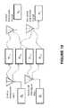
- FIG. 7illustrates an example of a 2-dimensional beamforming network subsystem 104 .
- the subsystemis realized in the digital domain as a tapped-delayline for each antenna polarization.
- the output of each tapped delaylineis summed with the outputs of the other delaylines for each antenna and polarization to form the output.
- Two 2D-BFNsare implemented, one for each polarization where the dimension of the 2D-BFNs are 2N 1 ⁇ K where K is the number of taps.
- FIG. 7shows signal flow a receiver described above. For the transmitter, the signal flow is reversed through the beamformer 104 .
- the computation of the weights for the 2D-BFNis mechanized by the weight control processor 104 c .
- the receiver signal vectors at the delay tapsare made available to the processor in order to compute the complex weights at each tap.
- a number of optimal and near optimal algorithmsare detailed in subsequent sections.
- the 2D-BFNmay be implement in hardware (discrete logic, ASICs, SOCs), software (on a DSP, CPU or GPU), or firmware (e.g. FPGA). Note the 2D-BFN may be implemented in the analog domain at baseband, IF or RF.
- two 2D-BFNsare implemented for each of the L TBRs attached to the CBR.
- N 2 antennasare processed.
- the dimension of the 2D-BRNsis 2N 2 ⁇ K where K is the number of taps.
- a pair of 2D-BRN of dimension N 2 ⁇ Kmay be used if the channel is reciprocal and the TBR uses a pair of 2N 2 ⁇ K 2D-BRN.
- the subsystem 104may contain an optional data direction feedback circuit 104 d . This circuit and its advantages will be described later in the description of the system.
- the baseband subsystem 106may further comprise a dual channel baseband radio processer (BRP).
- the BRPis comprised of a physical layer, media access controller (MAC) and a network layer.
- the physical (PHY) layerimplements modulation/demodulation, coding/decoding, encryption/decryption, and other PHY functions.
- the MACprovides frame building, scheduling, queuing, flow control, and layer 2 signaling.
- the network layerprovides the interface between the core network and MAC implementing encapsulation, packet inspection, shaping, policing, and QoS mechanism.
- the BRPcan be implemented with industry-wide radio standards such as GSM, W-CMDA, IEEE-802.16 and LTE or be implemented with a custom PHY and MAC.
- P2CMPpoint-to-concentrating multipoint
- Traditional MW backhauluses a point-to-point backhaul radio architecture.
- the point-to-concentrating multipoint (P2CMP) architectureshares the cost of all common CBR equipment such as antennas, transceivers, LNAs, PAs, filters, local oscillators, system control, backplanes, powering, and cabling cost over L TBRs with capacity Q per link, thus lowering the overall cost of each link.
- Traditional point to multipoint (P2MP)cannot make the same claim since the capacity per link is only Q/M.
- P2MPis normalized to the capacity of Q bps per link, the cost per link is often higher that the P2P equivalent, or the spectral efficiency is degraded by a factor of L such that spectrum cost become prohibitive.
- the system described hereinimplements simultaneous array adaption of all TBRs receiving the desired downlink CBR signals and sequential adaption of each end of the link.
- two independent data streamsare transmitted on the vertical and horizontal arrays from the CBR.
- All TBRscompute receiver weight vectors IV of the downlink that are applied to the TBR beamformers to estimate the downlink signals.
- the TBRsalso estimate the SINR, ⁇ right arrow over ( ⁇ ) ⁇ for the data stream(s) and sends it to the other end of the link as payload or signaling.
- the TBR transmit weightsare formed from the scaled conjugate of received weight vectors noting again the decoration denotes uplink.
- the transmit weightsare scaled by the power control variable and sent to the transmit beamformer where the uplink data is processed before sending the weighted data streams to the antenna arrays.
- the CBRthen receives all uplink signals from L TBRs and computes receiver weight vectors where j is the TBR link index.
- the uplink SINR jis also computed for each of the links and will be sent to the TBRs on the downlink.
- the transmit weights ⁇ right arrow over (g) ⁇ jare computed from the scaled conjugate of the receive weights ⁇ tilde over (w) ⁇ j and applied to the downlink data.
- w iis the N 1 ⁇ 1 weight vector at the end node for link i
- H ijis the N 1 ⁇ N 2 complex channel matrix for the CBR associated with link j to the end node associated with link i
- g jis the N 2 ⁇ 1 normalized downlink weight vector
- ⁇ square root over (p j ) ⁇is the complex transmit voltage on the downlink j
- d j (n)is the transmit signal for downlink j at time sample n
- ⁇ i (n)is a complex white Gaussian noise process seen at TBR i.
- the uplink and downlink RF channelsare depicted in FIG. 9 .
- the tilde decorationdenotes uplink in FIG. 9 . From FIG.
- the optimal transmitter weightsare the scaled conjugate of the receiver weights. This is known as retro-directive beamforming.
- the transmit poweris adaptively adjusted using an algorithm driven by the receive SINR and a target SINR ⁇ j , then the network of CBRs and TBRs will converge to their target SINRs using minimum total network power P as described in the equations above. If the total network power can be minimized, then interference into adjacent cells is minimized thus enhancing the capacity of these cells and the overall network performance in general.
- the target SINRis determined by the bit error rate requirements of the communication link as determined by the modulation and coding scheme.
- One simple method of power controlcomputes the new power level from last power level and ratio of the target SINR to the received SINR.
- ⁇ jis the target SINR to close the link at acceptable BER and ⁇ is the SINR as defined above
- the systemhas equalization gains (to be defined later) since the system needs the per-subcarrier equalization to be reflected in the power control on the transmit side of the equation.
- the effectis cumulative over all the nodes in the network. Note this algorithm estimates the SINR of link continuously. If it is too high with respect to the target SINR, then the next Tx power is reduced by ratio between the target and current SINR.
- Each receiverwill optimize its beamformer weights by maximizing the SINRs at both ends of the link. Normally we place no constraints on the weights. However it is possible to place structural constraints on the weights to simplify computations. If our optimization process increases the SINR and if our SINR targets remain constant; we will necessarily obtain a new solution that decreases all of the transmit powers and thus reducing P according to the equation above.
- the model of the received data x(n)can be expressed as the sum of multipath signals arriving on p distinguishable paths each with steering vector a p .
- the received dataalso includes spatial white Gaussian interference i(n) generated.
- ⁇ square root over ( ⁇ p ) ⁇ e ⁇ j ⁇ pis the amplitude and phase of path p
- a pis the steering vector for path p
- ⁇ pis the time delay for path p
- d(n)is the transmitted data
- i(n)is the interference vector modeled as Gaussian white noise.
- the dimension of matrix Ais N antenna sensors by P multipaths.
- An estimate ⁇ circumflex over (d) ⁇ (n) of the original signal d(n)can be realized by processing the received data with a 2-dimensional filter in the dimensions of space and time, hence a space-time adaptive processor (STAP).
- This filtermay be written as the linear convolution of receive vector x(n) at time n with the K 1 +K 2 +1 time taps of the filter where each time tap has coefficients w H (k) for ⁇ K 1 ⁇ k ⁇ K 2 ;
- the error between the output of the STAP filter ⁇ circumflex over (d) ⁇ (n) and the desired signal d(n)can be expressed as ⁇ (n).
- ⁇ (n)The error between the output of the STAP filter ⁇ circumflex over (d) ⁇ (n) and the desired signal d(n) can be expressed as ⁇ (n).
- the time averaged error powercan be written as follows:
- the partial differentials with respect to the tap weightscan be taken as follows:
- DFTDiscrete Fourier Transform
- an FFT and IFFTcan be used to replace the DFT in the above equations.
- the weight solution for the space-time filterrequires the formation of K covariance matrices of dimension N ⁇ N and K cross-correlation vectors of length N. This is a considerable reduction in computation complexity compared to the original problem.
- R xis the Cholesky factor of the covariance matrix R xx .
- the 2-dimensional STAP beamformermay be realized in the frequency domain by exploiting the Fourier Transform of the baseband signals from the array.
- the signalis “channelized” by the transform into multiple frequency subbands such that the array response is constant or nearly constant across the subchannel.
- the subchannel frequency supportshould be a fraction of the inverse of the RMS delay dispersion of the signal's multi-path components.
- narrowband beamformingmay be performed on each subchannel. This is known as Space Frequency Adaptive Processing (SFAP).
- SFAPSpace Frequency Adaptive Processing
- SFAPmay be the preferred embodiment for many signal types including OFDM, OFDMA and SC-FDMA. These signals are naturally constructed in the frequency domain using data subchannels, pilots for demodulation and preambles as can be observed by examining the specifications for LTE and 802.16.
- Xis the received signal matrix of M rows of time samples by N antennas
- wis the CBR receive beamforming weight vector of length K
- dis the desired symbol vector of length M
- eis the error in this model due to noise plus interference.
- R xthe Cholesky factor matrix of the auto-correlation matrix and is a N by N upper-triangular matrix.
- the formulation of the (A1) through (A15)assumes that the matrix X contains M subcarriers in the estimation of the first and second order statistics. For each subcarrier, this may be satisfied by collecting M subcarriers over the time interval of JT s where T s is the symbol time of the OFDM(A) baseband. J is selected to satisfy certain constraints dictated by the mis-adjustment of the linear combiner with respect to the desired signal.
- a nominal figure of merit for Mis 4 times the degrees of freedom (4 ⁇ DOF) for a mis-adjustment loss of ⁇ 1 dB.
- TBPtime-bandwidth product
- This formulationis valid provided that the phase and amplitude of the steering vector is relatively constant over the subband of M sc subcarriers. In fact, this method is advantageous in lowering the number of training symbols to meet the TBR required for link adaption.
- the methodmay add a final processing step to improve performance for a constrained number of subcarriers and model the collection of data over the subband as a constant steering vector perturbed by small variation in phase and amplitude. Often, this is a low order model in both amplitude and phase. Hence, is a small phase and amplitude ramp across the subband can be estimated accurately by pilot subcarriers present/insert in the baseband of the signal (e.g. Wimax and LTE).
- the final processing in the frequency domainis to collect the first and second order statistics and to estimate the post beamforming phase and amplitude tilt across the subband for receiver processing. Then upon transmit, conjugate the phase and apply the amplitude corrections while applying them to the transmitter weight derived from the receiver weight vector.
- the phase and amplitude tiltis unique for each subcarrier within in the subband.
- each subcarrierhas a unique linear combiner Rx weight and Tx weight conjugate.
- This processis defined as subband equalization and yield superior network performance. It is an additional component in achieving EIC.
- Equalizationin this context, optimizes components of W.
- the methodis refusing to optimize over all the components of G.
- the degrees of freedom associated with just the equalization componentsthat's half the degrees of freedom in the network and this performance suffers.
- Better performanceis achieved optimizing both transmit and receive weights according to min w min G P(W,G).
- Reciprocityproves that the optimal G are the conjugate of the concentrator receiver weights and thus are included the equalization gains as well. The effect is cumulative over all the nodes in the network.
- P(W,G)is reciprocal means that optimizing over equalization gains and transmitting with them necessarily improves all nodes in the network.
- the real-time capacity requirements of equipment attachedi.e. a base station
- MCSmodulation and coding scheme
- Thisis known as MCS downshifting and upshifting.
- a moving average of the uplink and downlink capacityis computed by subtracting the “filler” symbols from the total symbols in order to estimate the number of “traffic” symbols.
- a new and lower MCS levelis computed that would essentially pack all symbols and remove the filler. Headroom is added to this computation so as not to remove all filler. This is now the safe MCS level and the downshift can be commanded to the new level via PHY signaling (e.g.
- MAPMAP
- the data queues for the uplink and downlinkare monitored. If these are not emptied on each transmission interval, a higher MCS is warranted and the safe MCS level can be computed from a queue statistics.
- the upshiftcan be commanded to the new level via PHY signaling (e.g. MAP). Since the SINR requirements are lower for a MCS downshift, the TX power of the link can be lowered reducing interference power. Thus, downshifting increases the overall capacity of the network by allowing additional links (>L) or higher MCS levels for other links.
- the TBRsmay establish connections to multiple CBRs for the purpose of selecting the best serving CBR.
- the best serving CBRmay be sensed by computing the SINR of each link, estimating the quality of the multipath channel, determining the loading of the CBR, estimating the potential SINR degradation to other links currently connected to the CBR, or any combinations of these metrics.
- the TBRwill then request connection to the best serving CBR and generate a neighbor list of other CBRs.
- the listwill include the required timing parameters and power levels to each CBR.
- a TBRcan quickly switch over to another CBR if either the CBR fails or the propagation channel becomes impaired. This provides a level of network resiliency and reliability.
- the full capacity Q bps of each linkcan be subdivided into L sb sublinks with each with capacity Q/L s b. This maybe realized by using L sb subbands in the frequency domain. Alternately, a frame of data symbols may be divided into L sb subzones in the time domain. Note, that various linear combinations of capacity may be realized by aggregating integer numbers of subbands and/or subzones. A combination of subbanding and subzoning is also supported.
- the systemmay transmit with two independent data streams d 1 (n) and d 2 (n) on two different polarization with transmit weight g 1 and g 2 , respectively. This effectively doubles the data rate.
- d 1 (n) and d 2 (n)on two different polarization with transmit weight g 1 and g 2 , respectively.
- the receiversees a mixture of the desired data d 1 (n) via the principle channel matrix H 11 and an interference term d 2 (n) via the cross coupling matrix of the other polarization H 12 according the first equation below.
- the receiver for the orthogonal polarizationsees a mixture the desired data d 2 (n) via the principle channel matrix H 22 and an interference term d 1 (n) via the cross coupling term of the other polarization H 21 according the second equation below.
- x 1 ( n )H 11 g 1 ⁇ square root over ( p 1 ) ⁇ d 1 ( n )+ H 12 g 2 ⁇ square root over ( p 2 ) ⁇ d 2 ( n )+ i 1 ( n ) (F1a)
- x 2 ( n )H 21 g 1 ⁇ square root over ( p 1 ) ⁇ d 1 ( n )+ H 22 g 2 ⁇ square root over ( p 2 ) ⁇ d 2 ( n )+ i 2 ( n ) (F1b)
- the first equationmaybe recast as the desired signal being received on aperture a 11 (n) in the presence of cross-coupled interference on aperture a 12 (n) and generalized interference aperture i 1 (n) where the apertures are defined here.
- a 11 ( n )H 11 g 1 (F2a)
- a 12 ( n )H 12 g 2 (F2b)
- the optimal weights for the down link(CBR to TBR) can be computed by forming the 2N 1 ⁇ 1 receiver data vector and computing the relevant first and second order statistics below. This is the optimal MMSE solution for narrowband signals.
- x ⁇ ( n )[ x 1 ⁇ ( n ) x 2 ⁇ ( n ) ] ( F ⁇ ⁇ 3 ⁇ a )
- w ⁇ 1R xx - 1 ⁇ R xd 1 ( F ⁇ ⁇ 4 ⁇ a )
- w ⁇ 2R xx - 1 ⁇ R xd 2 ( F ⁇ ⁇ 4 ⁇ b )
- the weight solutionscan be computed as above with 2N 2 degrees of freedom, or with substantially lower complexity via the equations below.
- this inventioncomputes weights using x 1 (n) and x 2 (n) instead of x(n).
- the polarization wavefrontsarrive without cross-coupling since the TBR transmit weights were derived from the conjugate of the downlink TBR receive weights which are known to removed the cross-coupling components.
- 1R x 1 N 1 ⁇ 1 R N 1 d 1 (F5a)
- 2R x 2 N 2 ⁇ 1 R N 2 d 2 (F5b)
- any orthogonally polarized antennas setsmay be substituted with the same result such as verticaland horizontal, slant left and right, or RHCP and LHCP.
- the reference signals for link adaptionmay be realized from special training symbols, embedded pilots (e.g OFDM pilots for data demodulation), preambles, statistical significant data replications, baseband signal replications (e.g. cyclic prefix) in either the time or frequency domain, the signal's known constellation (known modulus), or by data directed feedback techniques using payload data or by combinations of above.
- embedded pilotse.g OFDM pilots for data demodulation
- preamblese.g. OFDM pilots for data demodulation
- statistical significant data replicationse.g. OFDM pilots for data demodulation
- baseband signal replicationse.g. cyclic prefix
- the signal's known constellationknown modulus
- the CBRsends the desired vertical and horizontal reference signals d v (k) and d h (k) on the vertical and horizontal array respectively simultaneously.
- the reference signalsare generated by modulating OFMDA subcarriers in the frequency domain using elements of codes derived from CAZAC sequences. Alternately, the reference signals can be the modulation on the data symbols of a single carrier in the time domain.
- CAZAC codesare a set of orthogonal codes with constant amplitude and zero circular auto-correlation and low circular cross-correlation. Hence d v (k) and d h (k) have low or zero cross-correlation.
- CAZAC codes from the same familyare assigned to each TBR within the footprint of the CBR.
- R xx ⁇ 1 and R xdare estimated over a block of P*L/B subcarriers containing the reference signals where P is the number of OFMDA symbols modulated by the reference signal and B is the number of subbands.
- a subbandis defined as a group of KB adjacent subcarriers where the relative differences between steering vectors measured on each member subcarrier as small.
- the linear combiner weights for the receiverare updated for each block of reference signal subcarriers.
- the SINR of the received signalmaybe also estimated over this block. The SINR is useful for transmission power control when relayed to the other end of the link.
- the 2D-BFN weight accuracy derived from abovecan be enhanced by computing the first and second order statistics over a longer time interval not limited to the reference symbols.
- the data payload part of the framemay be used.
- One embodimentcorrelates a delayed copy of the received data at multiple tap delays with an estimate of the data re-modulated using the same modulation and coding scheme (MCS) of the link. The data covariance is computed over this same time interval.
- MCSmodulation and coding scheme
- DDFmay extract reference symbols from the entire receive interval. This enables robust interference cancellation of unmanaged interference occurring in the data payload part of the subframe and but not available in the reference symbol part of the subframe. In this case, this is the preference embodiment for unlicensed frequency bands or licensed bands with unmanaged interference.
- the CBRperforms a link “concentration” function by simultaneously connecting to L TBRs using L (single polarization) or 2L (dual polarization) sets of STAP weights.
- Lsingle polarization
- 2Ldual polarization
- d lshould have low or zero cross-correlation among all d j where j ⁇ l.
- u lis the index over L links connected to the CBR and 1 ⁇ l ⁇ L. Note for best performance, d l should have low or zero cross-correlation among all d l where j ⁇ l.
- the CBR antenna power delivered by each power amplifier (PA)is the sum of all powers for L links as weighted by the complex element g m of the transmit weight vector g where m is the antenna/PA index.
- Powermust be allocated to each link to maintain the target SINR and the total power to each PA cannot exceed the P PA .
- One techniqueis to allocate equal maximum power P PA /L for each link. This is a very conservative method and suboptimal since some links require more power and some require less due to distance variation from the CBR. This method causes the power required at the PA to be over specified.
- pis the initial estimate of the link powers derived from initial ranging.
- the power p pa to each PAcan then be evaluated using the power scaling factors from each of L transmit weights contained in G post multiplied by the initial estimate of p max .
- a new p maxcan be computed by a variety of functions, methods and/or iterations. If there is a reasonable spread between power requirements of the links due to “near-far” distance variation, then this method yields significantly better performance.
- This systemmay thus be called dynamic multiuser power allocation and can improve the power available to TBRs at the edge of coverage by 2-6 dB depending on L, N 1 , N 2 and spatial distribution of the end points.
Landscapes
- Engineering & Computer Science (AREA)
- Computer Networks & Wireless Communication (AREA)
- Signal Processing (AREA)
- Radio Transmission System (AREA)
- Mobile Radio Communication Systems (AREA)
Abstract
Description


yi(n)=wiHHijgj√{square root over (pj)}{dot over (a)}j(n)+wiεi(n)
γi≡|wiHHiigi|2pi/Σj≠i|wiHHijgj|2pj+σ32wiHwi (A1)
γi≡Tiipi/Σj≠iTijpj+ρ32 (A2)
T↓ij≡(w→↓i↑HH↓ijw←↓j↑*p↓i)/(∥w→↓i↑|↑2∥w←↓∥↑2) (A3)
g↓≡(w←↓j↑*)/∥w←↓j↑∥↑2 (A4)
p=[p0,p1. . . pN-1]T (A5)
P=1Tp (A6)
p(l+1)=p(l)*
x(n)=Ad(n)+i(n) (B1)
A≡[a1,a2, . . . aP] (B2)
d(n)≡[√{square root over (α1)}e−jθ
rxd(−k)≡<x(n−k)d*(n))n (C16)
Rxx(k′,−k)≡Rxx(k′−k)≡<x(n−k)xH(n−k′)>n (C17)
RXXW=Rxd (C19)
- where
FE≡[ωmk] For 0≦m,k≦K−1 and ω=e−j2π/K (D1)
F−1=FH (D2)
W(k′)=F−1
Xw=d+e (E1)
XHXw=XHd+XHe (E2)
XHe=0 (E3)
Rxxw=Rxd (E4)
Rxx=XHX (E5)
Rxd=XHd (E6)
w=Rxx−1Rxd (E7)
e=X(XHX)−1XHd−d (E8)
σe2=eHe/N (E9)
Nσe2==dHd−dHX(XHX)−1XHd (E10)
Nσe2=dHd−Re(RxdHw) (E11)
X′=QRx (E11a)
QHQ=I (E11b)
Rxx=RxHQHQRx (E11c)
Rxx=RHxRx (E12)
Nσe2=dHd−RxdH(RxHRx)−1Rxd (E13)
Nσe2=dHd−uHu (E14)
u=Rx−HRxd (E15)
RxHu=Rxd (E15a)
w=Rx−1Rx−HRxd (E15b)
Rxw=Rx−HRxd (E15c)
Rxw=u (E15d)
x1(n)=H11g1√{square root over (p1)}d1(n)+H12g2√{square root over (p2)}d2(n)+i1(n) (F1a)
x2(n)=H21g1√{square root over (p1)}d1(n)+H22g2√{square root over (p2)}d2(n)+i2(n) (F1b)
a11(n)=H11g1 (F2a)
a12(n)=H12g2 (F2b)

d(k)=e−j2πr/L[k
w=Rxx−1Rxd (F6)
ul=Rx−1Rxd
Rxwl=ul (G3)
p=[p0,p1. . . pL-1]T (H1)
P=1Tp (H2)
p→pmax□ (H3)
ppa=Gpmax□ (H4)
f[pmax pa,ppa]□→pmax□ (H5)
Claims (18)
Priority Applications (6)
| Application Number | Priority Date | Filing Date | Title |
|---|---|---|---|
| US13/445,869US9456354B2 (en) | 2012-04-12 | 2012-04-12 | Non-line of sight wireless communication system and method |
| US14/214,229US9735940B1 (en) | 2012-04-12 | 2014-03-14 | System architecture for optimizing the capacity of adaptive array systems |
| US15/012,615US10432275B2 (en) | 2012-04-12 | 2016-02-01 | Non-line of sight wireless communication system and method |
| US15/640,980US11025394B1 (en) | 2012-04-12 | 2017-07-03 | System architecture for optimizing the capacity of adaptive array systems |
| US16/589,019US11831372B2 (en) | 2012-04-12 | 2019-09-30 | Non-line of sight wireless communication system and method |
| US17/326,780US12206616B1 (en) | 2012-04-12 | 2021-05-21 | Duplexing transceivers, system, and methods for optimizing the capacity of adaptive communication systems |
Applications Claiming Priority (1)
| Application Number | Priority Date | Filing Date | Title |
|---|---|---|---|
| US13/445,869US9456354B2 (en) | 2012-04-12 | 2012-04-12 | Non-line of sight wireless communication system and method |
Related Parent Applications (1)
| Application Number | Title | Priority Date | Filing Date |
|---|---|---|---|
| US13/445,861ContinuationUS9325409B1 (en) | 2012-04-12 | 2012-04-12 | Non-line of sight wireless communication system and method |
Related Child Applications (3)
| Application Number | Title | Priority Date | Filing Date |
|---|---|---|---|
| US13/445,863ContinuationUS9252908B1 (en) | 2012-04-12 | 2012-04-12 | Non-line of sight wireless communication system and method |
| US13/445,863Continuation-In-PartUS9252908B1 (en) | 2012-04-12 | 2012-04-12 | Non-line of sight wireless communication system and method |
| US14/214,229Continuation-In-PartUS9735940B1 (en) | 2012-04-12 | 2014-03-14 | System architecture for optimizing the capacity of adaptive array systems |
Publications (2)
| Publication Number | Publication Date |
|---|---|
| US20160135060A1 US20160135060A1 (en) | 2016-05-12 |
| US9456354B2true US9456354B2 (en) | 2016-09-27 |
Family
ID=55913310
Family Applications (1)
| Application Number | Title | Priority Date | Filing Date |
|---|---|---|---|
| US13/445,869Active2034-04-26US9456354B2 (en) | 2012-04-12 | 2012-04-12 | Non-line of sight wireless communication system and method |
Country Status (1)
| Country | Link |
|---|---|
| US (1) | US9456354B2 (en) |
Cited By (18)
| Publication number | Priority date | Publication date | Assignee | Title |
|---|---|---|---|---|
| US20170338921A1 (en) | 2011-10-17 | 2017-11-23 | Golba Llc | Method and system for high-throughput and low-power communication links in a distributed transceiver network |
| US10110270B2 (en) | 2013-03-14 | 2018-10-23 | Tarana Wireless, Inc. | Precision array processing using semi-coherent transceivers |
| US10321332B2 (en) | 2017-05-30 | 2019-06-11 | Movandi Corporation | Non-line-of-sight (NLOS) coverage for millimeter wave communication |
| US20190181916A1 (en)* | 2017-12-08 | 2019-06-13 | Movandi Corporation | Controlled Power Transmission in Radio Frequency (RF) Device Network |
| US20190181560A1 (en) | 2017-12-08 | 2019-06-13 | Movandi Corporation | Signal Cancellation in Radio Frequency (RF) Device Network |
| US10348394B1 (en) | 2014-03-14 | 2019-07-09 | Tarana Wireless, Inc. | System architecture and method for enhancing wireless networks with mini-satellites and pseudollites and adaptive antenna processing |
| US10348371B2 (en) | 2017-12-07 | 2019-07-09 | Movandi Corporation | Optimized multi-beam antenna array network with an extended radio frequency range |
| US20190267721A1 (en) | 2018-02-26 | 2019-08-29 | Movandi Corporation | Waveguide antenna element-based beam forming phased array antenna system for millimeter wave communication |
| US10419943B1 (en) | 2018-06-15 | 2019-09-17 | At&T Intellectual Property I, L.P. | Overlay of millimeter wave (mmWave) on citizens broadband radio service (CBRS) for next generation fixed wireless (NGFW) deployment |
| US10432275B2 (en) | 2012-04-12 | 2019-10-01 | Tarana Wireless, Inc. | Non-line of sight wireless communication system and method |
| US10432798B1 (en) | 2018-05-25 | 2019-10-01 | At&T Intellectual Property I, L.P. | System, method, and apparatus for service grouping of users to different speed tiers for wireless communication |
| US10499456B1 (en) | 2013-03-15 | 2019-12-03 | Tarana Wireless, Inc. | Distributed capacity base station architecture for broadband access with enhanced in-band GPS co-existence |
| US10608727B2 (en) | 2012-08-08 | 2020-03-31 | Golba Llc | Method and system for a distributed configurable transceiver architecture and implementation |
| US10798537B2 (en) | 2018-07-09 | 2020-10-06 | At&T Intellectual Property I, L.P. | Next generation fixed wireless qualification tool for speed-tier based subscription |
| US20210143543A1 (en)* | 2018-08-03 | 2021-05-13 | Viasat, Inc. | Antenna array system with disparate beam forming networks and non-linear filtering to mitigate interference |
| US11018752B2 (en) | 2017-07-11 | 2021-05-25 | Silicon Valley Bank | Reconfigurable and modular active repeater device |
| US11025394B1 (en) | 2012-04-12 | 2021-06-01 | Tarana Wireless, Inc. | System architecture for optimizing the capacity of adaptive array systems |
| US11088457B2 (en) | 2018-02-26 | 2021-08-10 | Silicon Valley Bank | Waveguide antenna element based beam forming phased array antenna system for millimeter wave communication |
Families Citing this family (3)
| Publication number | Priority date | Publication date | Assignee | Title |
|---|---|---|---|---|
| US9338661B2 (en) | 2013-04-09 | 2016-05-10 | Maxlinear, Inc. | Spatial routing among microwave backhaul transceivers |
| US9716572B2 (en)* | 2014-10-30 | 2017-07-25 | At&T Intellectual Property I, L.P. | MIMO based adaptive beamforming over OFDMA architecture |
| KR102721403B1 (en)* | 2017-02-24 | 2024-10-25 | 삼성전자주식회사 | Apparatus and method for transmitting reference siganls in wireless communication system |
Citations (54)
| Publication number | Priority date | Publication date | Assignee | Title |
|---|---|---|---|---|
| WO1998020633A2 (en) | 1996-11-07 | 1998-05-14 | Wavtrace, Inc. | System and method for broadband millimeter wave data communication |
| US6122260A (en) | 1996-12-16 | 2000-09-19 | Civil Telecommunications, Inc. | Smart antenna CDMA wireless communication system |
| GB2350265A (en) | 1999-05-21 | 2000-11-22 | Adaptive Broadband Ltd | Using subscriber terminals to provide backhaul data channels |
| US6219561B1 (en) | 1996-10-18 | 2001-04-17 | Cisco Systems, Inc. | Wireless communication network using time-varying vector channel equalization for adaptive spatial equalization |
| US6289062B1 (en) | 1998-12-11 | 2001-09-11 | Nortel Networks Limited | Method and apparatus for high rate data communication utilizing an adaptive antenna array |
| WO2002005493A2 (en) | 2000-06-26 | 2002-01-17 | Aperto Networks, Inc. | High-capacity integrated wireless backhaul for broadband access networks |
| US20020042290A1 (en) | 2000-10-11 | 2002-04-11 | Williams Terry L. | Method and apparatus employing a remote wireless repeater for calibrating a wireless base station having an adaptive antenna array |
| WO2002063896A1 (en) | 2001-02-05 | 2002-08-15 | Soma Networks, Inc. | Wireless local loop antenna |
| US20030035468A1 (en) | 2001-05-17 | 2003-02-20 | Corbaton Ivan Jesus Fernandez | System and method for adjusting combiner weights using an adaptive algorithm in wireless communications system |
| US6580328B2 (en) | 1998-11-04 | 2003-06-17 | Broadcom Corporation | Lock detector for phase locked loops |
| US6795424B1 (en) | 1998-06-30 | 2004-09-21 | Tellabs Operations, Inc. | Method and apparatus for interference suppression in orthogonal frequency division multiplexed (OFDM) wireless communication systems |
| US6865169B1 (en) | 1999-11-02 | 2005-03-08 | Ipwireless, Inc. | Cellular wireless internet access system using spread spectrum and internet protocol |
| WO2005101882A1 (en) | 2004-04-19 | 2005-10-27 | Telefonaktiebolaget Lm Ericsson (Publ) | Dynamic allocation of radio resources |
| WO2007082142A2 (en) | 2006-01-12 | 2007-07-19 | Motorola, Inc. | Communicating user and backhaul data with the same wireless time-frequency resources in an sdma system |
| US7333455B1 (en) | 2004-04-27 | 2008-02-19 | Piping Hot Networks Ltd | Multiple input multiple output (MIMO) wireless communications system |
| US7340279B2 (en) | 2001-03-23 | 2008-03-04 | Qualcomm Incorporated | Wireless communications with an adaptive antenna array |
| WO2008033369A2 (en) | 2006-09-14 | 2008-03-20 | Interdigital Technology Corporation | Assigning cell and resource blocks by optimizing interference |
| US7366120B2 (en) | 2004-10-18 | 2008-04-29 | Nortel Networks, Ltd | Method and apparatus for improving quality of service over meshed bachaul facilities in a wireless network |
| US20080117101A1 (en) | 2006-11-17 | 2008-05-22 | Vic Pan | Geo-location using distributed composite gps signals |
| US20080130496A1 (en) | 2006-12-01 | 2008-06-05 | Bandrich Inc. | Method and system for video transmission using 3g mobile network |
| US20080233967A1 (en) | 2007-03-23 | 2008-09-25 | Juan Montojo | Backhaul communication for interference management |
| US20080247388A1 (en) | 2007-04-03 | 2008-10-09 | Qualcomm Incorporated | Transferring a session in a cluster |
| US20080261602A1 (en) | 2007-04-18 | 2008-10-23 | Qualcomm Incorporated | Backhaul network for femto base stations |
| US20080317014A1 (en) | 2007-06-21 | 2008-12-25 | Elektrobit Wireless Communications Ltd. | Method for optimizing spatial modulation in a wireless link and network element thereto |
| US7493129B1 (en) | 2002-09-12 | 2009-02-17 | At&T Mobility Ii Llc | Method and apparatus to maintain network coverage when using a transport media to communicate with a remote antenna |
| US7502355B2 (en) | 2005-03-04 | 2009-03-10 | Cisco Technology, Inc. | Adaptive multiplexing device for multi-carrier wireless telecommunication systems |
| US20090110033A1 (en)* | 1998-02-12 | 2009-04-30 | Lot 41 Acquisition Foundation, Llc | Multicarrier sub-layer for direct sequence channel and multiple-access coding |
| EP2071745A1 (en) | 2007-12-14 | 2009-06-17 | Sony Corporation | Beam steering algorithm for NLOS wireless systems with predefined parameters |
| US7567543B2 (en) | 2005-10-24 | 2009-07-28 | Nec Laboratories America, Inc. | Method and apparatus for cross layer resource allocation for wireless backhaul networks |
| WO2009119463A2 (en) | 2008-03-27 | 2009-10-01 | Mitsubishi Electric Corporation | Method for allocating channel resources in orthogonal frequency-division multiple access network |
| US7640020B2 (en) | 2005-12-19 | 2009-12-29 | Motorola, Inc. | Method and apparatus for assigning backhaul methods |
| US7646752B1 (en) | 2003-12-31 | 2010-01-12 | Nortel Networks Limited | Multi-hop wireless backhaul network and method |
| WO2010003509A1 (en) | 2008-06-17 | 2010-01-14 | Nec Europe Ltd. | Method of subcarrier allocation in an ofdma-based communication network and network |
| WO2010013245A1 (en) | 2008-07-29 | 2010-02-04 | Alvarion Ltd. | Uplink resource control |
| US20100035620A1 (en) | 2008-08-07 | 2010-02-11 | Nortel Networks Limited | Wireless system |
| US20100046595A1 (en) | 2008-08-19 | 2010-02-25 | Qualcomm Incorporated | Semi-coherent timing propagation for geran multislot configurations |
| US7688739B2 (en) | 2005-08-02 | 2010-03-30 | Trilliant Networks, Inc. | Method and apparatus for maximizing data transmission capacity of a mesh network |
| US20100087149A1 (en) | 2008-09-30 | 2010-04-08 | Murari Srinivasan | Measuring communicating and using interference information |
| US7720444B2 (en) | 1999-10-21 | 2010-05-18 | Broadcom Corporation | Adaptive radio transceiver with a local oscillator |
| US20100195619A1 (en) | 2009-02-05 | 2010-08-05 | Mitsubishi Electric Corporation | Method and a device for adjusting the transmission power of signals |
| US20100215032A1 (en) | 2009-02-20 | 2010-08-26 | Beceem Communications Inc. | Synchronization and Frame Structure Determination of a Base Station |
| US20100254295A1 (en) | 2009-04-03 | 2010-10-07 | Electronics And Telecommunications Research Institute | Multicast and broadcast data transmission method |
| US7839856B2 (en) | 2007-06-06 | 2010-11-23 | Cisco Technology, Inc. | Centrally controlled routing with tagged packet forwarding in a wireless mesh network |
| US20110039509A1 (en) | 2009-08-13 | 2011-02-17 | Wolfgang Bruchner | Wireless receiver |
| US20110051731A1 (en) | 2009-08-31 | 2011-03-03 | Xiaowen Mang | Methods and apparatus to reassign quality of service priorities in a communication network |
| US20110269410A1 (en) | 2010-04-28 | 2011-11-03 | Mitsubishi Heavy Industries, Ltd. | Radio communication apparatus, radio network system, and data link construction method used for the same |
| US20110274032A1 (en) | 2009-01-06 | 2011-11-10 | Xiaobing Leng | Base station, relay station, mobile terminal for implementing relay and the corresponding method |
| WO2012037643A1 (en) | 2010-09-13 | 2012-03-29 | Blinq Wireless Inc. | System and method for co-channel interference measurement and managed adaptive resource allocation for wireless backhaul |
| US20120108257A1 (en) | 2010-10-27 | 2012-05-03 | Korea Advanced Institute Of Science And Technology | Communication method of base station and target terminal |
| US20120129539A1 (en) | 2010-11-19 | 2012-05-24 | Seyed Mohammad Ali Arad | Method and System for Frequency Reuse in Multi-Cell Deployment Model of a Wireless Backhaul Network |
| US20130094522A1 (en) | 2011-10-17 | 2013-04-18 | Mehran Moshfeghi | Method and system for utilizing multiplexing to increase throughput in a network of distributed transceivers with array processing |
| US20130142136A1 (en)* | 2011-10-21 | 2013-06-06 | Samsung Electronics Co., Ltd. | Methods and apparatus for adaptive wireless backhaul and networks |
| US8502733B1 (en) | 2012-02-10 | 2013-08-06 | CBF Networks, Inc. | Transmit co-channel spectrum sharing |
| US8531471B2 (en) | 2008-11-13 | 2013-09-10 | Intel Corporation | Shared virtual memory |
- 2012
- 2012-04-12USUS13/445,869patent/US9456354B2/enactiveActive
Patent Citations (59)
| Publication number | Priority date | Publication date | Assignee | Title |
|---|---|---|---|---|
| US6219561B1 (en) | 1996-10-18 | 2001-04-17 | Cisco Systems, Inc. | Wireless communication network using time-varying vector channel equalization for adaptive spatial equalization |
| WO1998020633A2 (en) | 1996-11-07 | 1998-05-14 | Wavtrace, Inc. | System and method for broadband millimeter wave data communication |
| US6122260A (en) | 1996-12-16 | 2000-09-19 | Civil Telecommunications, Inc. | Smart antenna CDMA wireless communication system |
| US20090110033A1 (en)* | 1998-02-12 | 2009-04-30 | Lot 41 Acquisition Foundation, Llc | Multicarrier sub-layer for direct sequence channel and multiple-access coding |
| US6795424B1 (en) | 1998-06-30 | 2004-09-21 | Tellabs Operations, Inc. | Method and apparatus for interference suppression in orthogonal frequency division multiplexed (OFDM) wireless communication systems |
| US6580328B2 (en) | 1998-11-04 | 2003-06-17 | Broadcom Corporation | Lock detector for phase locked loops |
| US6289062B1 (en) | 1998-12-11 | 2001-09-11 | Nortel Networks Limited | Method and apparatus for high rate data communication utilizing an adaptive antenna array |
| GB2350265A (en) | 1999-05-21 | 2000-11-22 | Adaptive Broadband Ltd | Using subscriber terminals to provide backhaul data channels |
| US7720444B2 (en) | 1999-10-21 | 2010-05-18 | Broadcom Corporation | Adaptive radio transceiver with a local oscillator |
| US6865169B1 (en) | 1999-11-02 | 2005-03-08 | Ipwireless, Inc. | Cellular wireless internet access system using spread spectrum and internet protocol |
| WO2002005493A2 (en) | 2000-06-26 | 2002-01-17 | Aperto Networks, Inc. | High-capacity integrated wireless backhaul for broadband access networks |
| US20020042290A1 (en) | 2000-10-11 | 2002-04-11 | Williams Terry L. | Method and apparatus employing a remote wireless repeater for calibrating a wireless base station having an adaptive antenna array |
| WO2002063896A1 (en) | 2001-02-05 | 2002-08-15 | Soma Networks, Inc. | Wireless local loop antenna |
| US7340279B2 (en) | 2001-03-23 | 2008-03-04 | Qualcomm Incorporated | Wireless communications with an adaptive antenna array |
| US20030035468A1 (en) | 2001-05-17 | 2003-02-20 | Corbaton Ivan Jesus Fernandez | System and method for adjusting combiner weights using an adaptive algorithm in wireless communications system |
| US7493129B1 (en) | 2002-09-12 | 2009-02-17 | At&T Mobility Ii Llc | Method and apparatus to maintain network coverage when using a transport media to communicate with a remote antenna |
| US20100067476A1 (en) | 2003-12-31 | 2010-03-18 | Nortel Networks Limited | Multi-hop wireless backhaul network and method |
| US7646752B1 (en) | 2003-12-31 | 2010-01-12 | Nortel Networks Limited | Multi-hop wireless backhaul network and method |
| WO2005101882A1 (en) | 2004-04-19 | 2005-10-27 | Telefonaktiebolaget Lm Ericsson (Publ) | Dynamic allocation of radio resources |
| US7333455B1 (en) | 2004-04-27 | 2008-02-19 | Piping Hot Networks Ltd | Multiple input multiple output (MIMO) wireless communications system |
| US7366120B2 (en) | 2004-10-18 | 2008-04-29 | Nortel Networks, Ltd | Method and apparatus for improving quality of service over meshed bachaul facilities in a wireless network |
| US7502355B2 (en) | 2005-03-04 | 2009-03-10 | Cisco Technology, Inc. | Adaptive multiplexing device for multi-carrier wireless telecommunication systems |
| US7688739B2 (en) | 2005-08-02 | 2010-03-30 | Trilliant Networks, Inc. | Method and apparatus for maximizing data transmission capacity of a mesh network |
| US7567543B2 (en) | 2005-10-24 | 2009-07-28 | Nec Laboratories America, Inc. | Method and apparatus for cross layer resource allocation for wireless backhaul networks |
| US7640020B2 (en) | 2005-12-19 | 2009-12-29 | Motorola, Inc. | Method and apparatus for assigning backhaul methods |
| WO2007082142A2 (en) | 2006-01-12 | 2007-07-19 | Motorola, Inc. | Communicating user and backhaul data with the same wireless time-frequency resources in an sdma system |
| WO2008033369A2 (en) | 2006-09-14 | 2008-03-20 | Interdigital Technology Corporation | Assigning cell and resource blocks by optimizing interference |
| US20080117101A1 (en) | 2006-11-17 | 2008-05-22 | Vic Pan | Geo-location using distributed composite gps signals |
| US20080130496A1 (en) | 2006-12-01 | 2008-06-05 | Bandrich Inc. | Method and system for video transmission using 3g mobile network |
| US20080233967A1 (en) | 2007-03-23 | 2008-09-25 | Juan Montojo | Backhaul communication for interference management |
| JP2010522516A (en) | 2007-03-23 | 2010-07-01 | クゥアルコム・インコーポレイテッド | Backhaul communication for interference management |
| US20080247388A1 (en) | 2007-04-03 | 2008-10-09 | Qualcomm Incorporated | Transferring a session in a cluster |
| US20080261602A1 (en) | 2007-04-18 | 2008-10-23 | Qualcomm Incorporated | Backhaul network for femto base stations |
| JP2010525678A (en) | 2007-04-18 | 2010-07-22 | クゥアルコム・インコーポレイテッド | Backhaul network for femto base stations |
| US7839856B2 (en) | 2007-06-06 | 2010-11-23 | Cisco Technology, Inc. | Centrally controlled routing with tagged packet forwarding in a wireless mesh network |
| US20080317014A1 (en) | 2007-06-21 | 2008-12-25 | Elektrobit Wireless Communications Ltd. | Method for optimizing spatial modulation in a wireless link and network element thereto |
| EP2071745A1 (en) | 2007-12-14 | 2009-06-17 | Sony Corporation | Beam steering algorithm for NLOS wireless systems with predefined parameters |
| WO2009119463A2 (en) | 2008-03-27 | 2009-10-01 | Mitsubishi Electric Corporation | Method for allocating channel resources in orthogonal frequency-division multiple access network |
| WO2010003509A1 (en) | 2008-06-17 | 2010-01-14 | Nec Europe Ltd. | Method of subcarrier allocation in an ofdma-based communication network and network |
| WO2010013245A1 (en) | 2008-07-29 | 2010-02-04 | Alvarion Ltd. | Uplink resource control |
| US20100035620A1 (en) | 2008-08-07 | 2010-02-11 | Nortel Networks Limited | Wireless system |
| US20100046595A1 (en) | 2008-08-19 | 2010-02-25 | Qualcomm Incorporated | Semi-coherent timing propagation for geran multislot configurations |
| US20100087149A1 (en) | 2008-09-30 | 2010-04-08 | Murari Srinivasan | Measuring communicating and using interference information |
| US8531471B2 (en) | 2008-11-13 | 2013-09-10 | Intel Corporation | Shared virtual memory |
| US20110274032A1 (en) | 2009-01-06 | 2011-11-10 | Xiaobing Leng | Base station, relay station, mobile terminal for implementing relay and the corresponding method |
| US20100195619A1 (en) | 2009-02-05 | 2010-08-05 | Mitsubishi Electric Corporation | Method and a device for adjusting the transmission power of signals |
| JP2010183573A (en) | 2009-02-05 | 2010-08-19 | Mitsubishi Electric R & D Centre Europe Bv | Method and device for adjusting transmission power of signal transferred and/or received by first base station, computer program product of the method, and method and device for transferring information for enabling adjustment of transmission power |
| US20100215032A1 (en) | 2009-02-20 | 2010-08-26 | Beceem Communications Inc. | Synchronization and Frame Structure Determination of a Base Station |
| US20100254295A1 (en) | 2009-04-03 | 2010-10-07 | Electronics And Telecommunications Research Institute | Multicast and broadcast data transmission method |
| US20110039509A1 (en) | 2009-08-13 | 2011-02-17 | Wolfgang Bruchner | Wireless receiver |
| US20110051731A1 (en) | 2009-08-31 | 2011-03-03 | Xiaowen Mang | Methods and apparatus to reassign quality of service priorities in a communication network |
| US20110269410A1 (en) | 2010-04-28 | 2011-11-03 | Mitsubishi Heavy Industries, Ltd. | Radio communication apparatus, radio network system, and data link construction method used for the same |
| WO2012037643A1 (en) | 2010-09-13 | 2012-03-29 | Blinq Wireless Inc. | System and method for co-channel interference measurement and managed adaptive resource allocation for wireless backhaul |
| US20120108257A1 (en) | 2010-10-27 | 2012-05-03 | Korea Advanced Institute Of Science And Technology | Communication method of base station and target terminal |
| US20120129539A1 (en) | 2010-11-19 | 2012-05-24 | Seyed Mohammad Ali Arad | Method and System for Frequency Reuse in Multi-Cell Deployment Model of a Wireless Backhaul Network |
| US20130094522A1 (en) | 2011-10-17 | 2013-04-18 | Mehran Moshfeghi | Method and system for utilizing multiplexing to increase throughput in a network of distributed transceivers with array processing |
| US20130142136A1 (en)* | 2011-10-21 | 2013-06-06 | Samsung Electronics Co., Ltd. | Methods and apparatus for adaptive wireless backhaul and networks |
| US8502733B1 (en) | 2012-02-10 | 2013-08-06 | CBF Networks, Inc. | Transmit co-channel spectrum sharing |
| US20130207841A1 (en)* | 2012-02-10 | 2013-08-15 | Kevin J. Negus | Transmit co-channel spectrum sharing |
Non-Patent Citations (7)
| Title |
|---|
| "Adaptive Frequency-Domain Equalization and Diversity Combining for Broadband Wireless Communications" by Martin V. Clark; IEEE Journal; dated Oct. 1998. |
| "Echo Cancellation and Channel Estimation for On-Channel Repeaters in DVB-T/H Networks" by Karim M. Nasr et al.; Brunel University; dated after Jan. 2006. |
| "Load- and Interference-Aware Channel Assignment for Dual-Radio Mesh Backhauls" by Michelle X. Gong et al.; IEEE Communications Society; dated 2008. |
| "Signal Acquisition and Tracking with Adaptive Arrays in the Digital Mobile Radio System IS-54 with Flat Fading" by Jack H. Winters; IEEE Transactions; dated Nov. 4, 1993. |
| "The Bits and Flops of the N-hop Multilateration Primitive for Node Localization Problems" by Andreas Savvides et al.; UCLA; dated Sep. 28, 2002. |
| PCT International Search Report of PCT/US14/26696; dated Sep. 19, 2014; (2 pgs.). |
| PCT Written Opinion of the International Searching Authority of PCT/US14/26696; dated Sep. 19, 2014; (4 pgs.). |
Cited By (46)
| Publication number | Priority date | Publication date | Assignee | Title |
|---|---|---|---|---|
| US10581567B2 (en) | 2011-10-17 | 2020-03-03 | Golba Llc | Method and system for high-throughput and low-power communication links in a distributed transceiver network |
| US11018816B2 (en) | 2011-10-17 | 2021-05-25 | Golba Llc | Method and system for a repeater network that utilizes distributed transceivers with array processing |
| US11075723B2 (en) | 2011-10-17 | 2021-07-27 | Golba Llc | Method and system for MIMO transmission in a distributed transceiver network |
| US10965411B2 (en) | 2011-10-17 | 2021-03-30 | Golba Llc | Method and system for a repeater network that utilizes distributed transceivers with array processing |
| US10958389B2 (en) | 2011-10-17 | 2021-03-23 | Golba Llc | Method and system for providing diversity in a network that utilizes distributed transceivers with array processing |
| US10873431B2 (en) | 2011-10-17 | 2020-12-22 | Golba Llc | Method and system for utilizing multiplexing to increase throughput in a network of distributed transceivers with array processing |
| US20170338921A1 (en) | 2011-10-17 | 2017-11-23 | Golba Llc | Method and system for high-throughput and low-power communication links in a distributed transceiver network |
| US11075724B2 (en) | 2011-10-17 | 2021-07-27 | Golba Llc | Method and system for a repeater network that utilizes distributed transceivers with array processing |
| US11108512B2 (en) | 2011-10-17 | 2021-08-31 | Golba Llc | Method and system for centralized or distributed resource management in a distributed transceiver network |
| US11128415B2 (en) | 2011-10-17 | 2021-09-21 | Golba Llc | Method and system for a repeater network that utilizes distributed transceivers with array processing |
| US11133903B2 (en) | 2011-10-17 | 2021-09-28 | Golba Llc | Method and system for centralized distributed transceiver management |
| US11831372B2 (en) | 2012-04-12 | 2023-11-28 | Tarana Wireless, Inc. | Non-line of sight wireless communication system and method |
| US10432275B2 (en) | 2012-04-12 | 2019-10-01 | Tarana Wireless, Inc. | Non-line of sight wireless communication system and method |
| US12206616B1 (en) | 2012-04-12 | 2025-01-21 | Tarana Wireless, Inc. | Duplexing transceivers, system, and methods for optimizing the capacity of adaptive communication systems |
| US11025394B1 (en) | 2012-04-12 | 2021-06-01 | Tarana Wireless, Inc. | System architecture for optimizing the capacity of adaptive array systems |
| US11128367B2 (en) | 2012-08-08 | 2021-09-21 | Golba Llc | Method and system for optimizing communication in leaky wave distributed transceiver environments |
| US10735079B2 (en)* | 2012-08-08 | 2020-08-04 | Golba Llc | Method and system for distributed transceivers and mobile device connectivity |
| US10608727B2 (en) | 2012-08-08 | 2020-03-31 | Golba Llc | Method and system for a distributed configurable transceiver architecture and implementation |
| US11552669B2 (en) | 2013-03-14 | 2023-01-10 | Tarana Wireless, Inc. | Precision array processing using semi-coherent transceivers |
| US10110270B2 (en) | 2013-03-14 | 2018-10-23 | Tarana Wireless, Inc. | Precision array processing using semi-coherent transceivers |
| US10499456B1 (en) | 2013-03-15 | 2019-12-03 | Tarana Wireless, Inc. | Distributed capacity base station architecture for broadband access with enhanced in-band GPS co-existence |
| US12255724B2 (en) | 2014-03-14 | 2025-03-18 | Tarana Wireless, Inc. | System architecture and method for duplexing with high mobility networks including air based nodes and computing devices |
| US11115111B1 (en) | 2014-03-14 | 2021-09-07 | Tarana Wireless, Inc. | System architecture and method for high mobility networking including air based nodes and computing devices |
| US10348394B1 (en) | 2014-03-14 | 2019-07-09 | Tarana Wireless, Inc. | System architecture and method for enhancing wireless networks with mini-satellites and pseudollites and adaptive antenna processing |
| US10721634B2 (en) | 2017-05-30 | 2020-07-21 | Movandi Corporation | Non-line-of-sight (NLOS) coverage for millimeter wave communication |
| US10321332B2 (en) | 2017-05-30 | 2019-06-11 | Movandi Corporation | Non-line-of-sight (NLOS) coverage for millimeter wave communication |
| US11018752B2 (en) | 2017-07-11 | 2021-05-25 | Silicon Valley Bank | Reconfigurable and modular active repeater device |
| US10587313B2 (en) | 2017-12-07 | 2020-03-10 | Movandi Corporation | Optimized multi-beam antenna array network with an extended radio frequency range |
| US10348371B2 (en) | 2017-12-07 | 2019-07-09 | Movandi Corporation | Optimized multi-beam antenna array network with an extended radio frequency range |
| US10862559B2 (en) | 2017-12-08 | 2020-12-08 | Movandi Corporation | Signal cancellation in radio frequency (RF) device network |
| US20190181916A1 (en)* | 2017-12-08 | 2019-06-13 | Movandi Corporation | Controlled Power Transmission in Radio Frequency (RF) Device Network |
| US20190181560A1 (en) | 2017-12-08 | 2019-06-13 | Movandi Corporation | Signal Cancellation in Radio Frequency (RF) Device Network |
| US10666326B2 (en)* | 2017-12-08 | 2020-05-26 | Movandi Corporation | Controlled power transmission in radio frequency (RF) device network |
| US10637159B2 (en) | 2018-02-26 | 2020-04-28 | Movandi Corporation | Waveguide antenna element-based beam forming phased array antenna system for millimeter wave communication |
| US11088457B2 (en) | 2018-02-26 | 2021-08-10 | Silicon Valley Bank | Waveguide antenna element based beam forming phased array antenna system for millimeter wave communication |
| US11108167B2 (en) | 2018-02-26 | 2021-08-31 | Silicon Valley Bank | Waveguide antenna element-based beam forming phased array antenna system for millimeter wave communication |
| US20190267721A1 (en) | 2018-02-26 | 2019-08-29 | Movandi Corporation | Waveguide antenna element-based beam forming phased array antenna system for millimeter wave communication |
| US10701217B2 (en) | 2018-05-25 | 2020-06-30 | At&T Intellectual Property I, L.P. | System, method, and apparatus for service grouping of users to different speed tiers for wireless communication |
| US10432798B1 (en) | 2018-05-25 | 2019-10-01 | At&T Intellectual Property I, L.P. | System, method, and apparatus for service grouping of users to different speed tiers for wireless communication |
| US11140560B2 (en) | 2018-06-15 | 2021-10-05 | At&T Intellectual Property I, L.P. | Overlay of millimeter wave (mmWave) on citizens broadband radio service (CBRS) for next generation fixed wireless (NGFW) deployment |
| US10419943B1 (en) | 2018-06-15 | 2019-09-17 | At&T Intellectual Property I, L.P. | Overlay of millimeter wave (mmWave) on citizens broadband radio service (CBRS) for next generation fixed wireless (NGFW) deployment |
| US11665550B2 (en) | 2018-06-15 | 2023-05-30 | At&T Intellectual Property I, L.P. | Overlay of millimeter wave (mmWave) on citizens broadband radio service (CBRS) for next generation fixed wireless (NGFW) deployment |
| US10694395B2 (en) | 2018-06-15 | 2020-06-23 | At&T Intellectual Property I, L.P. | Overlay of millimeter wave (mmWave) on citizens broadband radio service (CBRS) for next generation fixed wireless (NGFW) deployment |
| US10798537B2 (en) | 2018-07-09 | 2020-10-06 | At&T Intellectual Property I, L.P. | Next generation fixed wireless qualification tool for speed-tier based subscription |
| US12126091B2 (en)* | 2018-08-03 | 2024-10-22 | Viasat, Inc. | Antenna array system with disparate beam forming networks and non-linear filtering to mitigate interference |
| US20210143543A1 (en)* | 2018-08-03 | 2021-05-13 | Viasat, Inc. | Antenna array system with disparate beam forming networks and non-linear filtering to mitigate interference |
Also Published As
| Publication number | Publication date |
|---|---|
| US20160135060A1 (en) | 2016-05-12 |
Similar Documents
| Publication | Publication Date | Title |
|---|---|---|
| US11831372B2 (en) | Non-line of sight wireless communication system and method | |
| US9456354B2 (en) | Non-line of sight wireless communication system and method | |
| US9325409B1 (en) | Non-line of sight wireless communication system and method | |
| US12206616B1 (en) | Duplexing transceivers, system, and methods for optimizing the capacity of adaptive communication systems | |
| US11012136B2 (en) | Beamforming in a MU-MIMO wireless communication system with relays | |
| US11160078B2 (en) | Backhaul radio with adaptive beamforming and sample alignment | |
| US6377636B1 (en) | Method and wireless communications system using coordinated transmission and training for interference mitigation | |
| US8160013B2 (en) | Method of transmitting data in multi-cell cooperative wireless communication system | |
| US9100835B2 (en) | Method and apparatus of wireless communication using directional antennas | |
| JP2016506681A (en) | Method and apparatus for uplink power control in a wireless communication system based on beamforming | |
| Riera-Palou et al. | Enhancing cell-free Massive MIMO networks through leo satellite integration | |
| Femenias et al. | Reduced-complexity downlink cell-free mmWave massive MIMO systems with fronthaul constraints | |
| Okuyama et al. | Antenna deployment for 5G ultra high-density distributed antenna system at low SHF bands | |
| CN101807979A (en) | Method for multi-user pre-coding based on single-antenna power constraint in wireless communication | |
| Zhou et al. | Performance analysis of millimeter wave NOMA networks with beam misalignment | |
| Panda | Performance optimization of cell-free massive MIMO system with power control approach | |
| Riera-Palou et al. | Sleep mode strategies for energy efficient cell-free massive MIMO in 5G deployments | |
| Wang et al. | Ray-tracing based performance evaluation of 5G mmWave massive MIMO in hotspots | |
| EP3200357A1 (en) | Non-line of sight wireless communication system and method | |
| Salem et al. | Radio resource management in OFDMA-based cellular networks enhanced with fixed and nomadic relays | |
| HK1242059A1 (en) | Non-line of sight wireless communication system and method | |
| HK1242059A (en) | Non-line of sight wireless communication system and method | |
| Tateishi et al. | Experimental evaluation of advanced beam tracking with CSI acquisition for 5G radio access | |
| Kumagai et al. | Scheduler reducing CSI feedback overhead and computational complexity for 5G ultra high-density distributed antenna systems with hybrid BF | |
| Chen et al. | A novel interference suppression method in wireless relay networks |
Legal Events
| Date | Code | Title | Description |
|---|---|---|---|
| AS | Assignment | Owner name:TARANA WIRELESS, INC., CALIFORNIA Free format text:ASSIGNMENT OF ASSIGNORS INTEREST;ASSIGNOR:BRANLUND, DALE;REEL/FRAME:032139/0981 Effective date:20131022 | |
| STCF | Information on status: patent grant | Free format text:PATENTED CASE | |
| MAFP | Maintenance fee payment | Free format text:PAYMENT OF MAINTENANCE FEE, 4TH YR, SMALL ENTITY (ORIGINAL EVENT CODE: M2551); ENTITY STATUS OF PATENT OWNER: SMALL ENTITY Year of fee payment:4 | |
| AS | Assignment | Owner name:TRINITY CAPITAL INC., ARIZONA Free format text:SECURITY INTEREST;ASSIGNOR:TARANA WIRELESS, INC.;REEL/FRAME:056724/0885 Effective date:20210630 | |
| AS | Assignment | Owner name:TARANA WIRELESS, INC., CALIFORNIA Free format text:RELEASE OF SECURITY INTEREST IN INTELLECTUAL PROPERTY AT REEL/FRAME NO. 56724/0885;ASSIGNOR:TRINITY CAPITAL INC.;REEL/FRAME:062075/0067 Effective date:20221205 | |
| MAFP | Maintenance fee payment | Free format text:PAYMENT OF MAINTENANCE FEE, 8TH YR, SMALL ENTITY (ORIGINAL EVENT CODE: M2552); ENTITY STATUS OF PATENT OWNER: SMALL ENTITY Year of fee payment:8 | |
| AS | Assignment | Owner name:TRINITY CAPITAL INC., ARIZONA Free format text:SECURITY INTEREST;ASSIGNOR:TARANA WIRELESS, INC.;REEL/FRAME:068667/0768 Effective date:20240923 | |
| AS | Assignment | Owner name:BANC OF CALIFORNIA, NORTH CAROLINA Free format text:SECURITY INTEREST;ASSIGNOR:TARANA WIRELESS, INC.;REEL/FRAME:068709/0140 Effective date:20240924 |