US9451971B2 - Intramedullary fixation assembly and devices and methods for installing the same - Google Patents
Intramedullary fixation assembly and devices and methods for installing the sameDownload PDFInfo
- Publication number
- US9451971B2 US9451971B2US12/389,137US38913709AUS9451971B2US 9451971 B2US9451971 B2US 9451971B2US 38913709 AUS38913709 AUS 38913709AUS 9451971 B2US9451971 B2US 9451971B2
- Authority
- US
- United States
- Prior art keywords
- fixation member
- fastener
- spaced arms
- radius
- fixation
- Prior art date
- Legal status (The legal status is an assumption and is not a legal conclusion. Google has not performed a legal analysis and makes no representation as to the accuracy of the status listed.)
- Expired - Lifetime, expires
Links
Images


Classifications
- A—HUMAN NECESSITIES
- A61—MEDICAL OR VETERINARY SCIENCE; HYGIENE
- A61B—DIAGNOSIS; SURGERY; IDENTIFICATION
- A61B17/00—Surgical instruments, devices or methods
- A61B17/16—Instruments for performing osteoclasis; Drills or chisels for bones; Trepans
- A61B17/17—Guides or aligning means for drills, mills, pins or wires
- A61B17/1725—Guides or aligning means for drills, mills, pins or wires for applying transverse screws or pins through intramedullary nails or pins
- A—HUMAN NECESSITIES
- A61—MEDICAL OR VETERINARY SCIENCE; HYGIENE
- A61B—DIAGNOSIS; SURGERY; IDENTIFICATION
- A61B17/00—Surgical instruments, devices or methods
- A61B17/16—Instruments for performing osteoclasis; Drills or chisels for bones; Trepans
- A61B17/1662—Instruments for performing osteoclasis; Drills or chisels for bones; Trepans for particular parts of the body
- A61B17/1664—Instruments for performing osteoclasis; Drills or chisels for bones; Trepans for particular parts of the body for the hip
- A61B17/1668—Instruments for performing osteoclasis; Drills or chisels for bones; Trepans for particular parts of the body for the hip for the upper femur
- A—HUMAN NECESSITIES
- A61—MEDICAL OR VETERINARY SCIENCE; HYGIENE
- A61B—DIAGNOSIS; SURGERY; IDENTIFICATION
- A61B17/00—Surgical instruments, devices or methods
- A61B17/16—Instruments for performing osteoclasis; Drills or chisels for bones; Trepans
- A61B17/1662—Instruments for performing osteoclasis; Drills or chisels for bones; Trepans for particular parts of the body
- A61B17/1684—Instruments for performing osteoclasis; Drills or chisels for bones; Trepans for particular parts of the body for the shoulder
- A—HUMAN NECESSITIES
- A61—MEDICAL OR VETERINARY SCIENCE; HYGIENE
- A61B—DIAGNOSIS; SURGERY; IDENTIFICATION
- A61B17/00—Surgical instruments, devices or methods
- A61B17/56—Surgical instruments or methods for treatment of bones or joints; Devices specially adapted therefor
- A61B17/58—Surgical instruments or methods for treatment of bones or joints; Devices specially adapted therefor for osteosynthesis, e.g. bone plates, screws or setting implements
- A61B17/68—Internal fixation devices, including fasteners and spinal fixators, even if a part thereof projects from the skin
- A61B17/72—Intramedullary devices, e.g. pins or nails
- A—HUMAN NECESSITIES
- A61—MEDICAL OR VETERINARY SCIENCE; HYGIENE
- A61B—DIAGNOSIS; SURGERY; IDENTIFICATION
- A61B17/00—Surgical instruments, devices or methods
- A61B17/56—Surgical instruments or methods for treatment of bones or joints; Devices specially adapted therefor
- A61B17/58—Surgical instruments or methods for treatment of bones or joints; Devices specially adapted therefor for osteosynthesis, e.g. bone plates, screws or setting implements
- A61B17/88—Osteosynthesis instruments; Methods or means for implanting or extracting internal or external fixation devices
- A61B17/8875—Screwdrivers, spanners or wrenches
- A—HUMAN NECESSITIES
- A61—MEDICAL OR VETERINARY SCIENCE; HYGIENE
- A61B—DIAGNOSIS; SURGERY; IDENTIFICATION
- A61B17/00—Surgical instruments, devices or methods
- A61B17/16—Instruments for performing osteoclasis; Drills or chisels for bones; Trepans
- A61B17/1659—Surgical rasps, files, planes, or scrapers
- A—HUMAN NECESSITIES
- A61—MEDICAL OR VETERINARY SCIENCE; HYGIENE
- A61B—DIAGNOSIS; SURGERY; IDENTIFICATION
- A61B17/00—Surgical instruments, devices or methods
- A61B17/56—Surgical instruments or methods for treatment of bones or joints; Devices specially adapted therefor
- A61B17/58—Surgical instruments or methods for treatment of bones or joints; Devices specially adapted therefor for osteosynthesis, e.g. bone plates, screws or setting implements
- A61B17/68—Internal fixation devices, including fasteners and spinal fixators, even if a part thereof projects from the skin
- A61B17/84—Fasteners therefor or fasteners being internal fixation devices
- A61B17/846—Nails or pins, i.e. anchors without movable parts, holding by friction only, with or without structured surface
- A61B17/848—Kirschner wires, i.e. thin, long nails
- A—HUMAN NECESSITIES
- A61—MEDICAL OR VETERINARY SCIENCE; HYGIENE
- A61B—DIAGNOSIS; SURGERY; IDENTIFICATION
- A61B17/00—Surgical instruments, devices or methods
- A61B17/56—Surgical instruments or methods for treatment of bones or joints; Devices specially adapted therefor
- A61B17/58—Surgical instruments or methods for treatment of bones or joints; Devices specially adapted therefor for osteosynthesis, e.g. bone plates, screws or setting implements
- A61B17/68—Internal fixation devices, including fasteners and spinal fixators, even if a part thereof projects from the skin
- A61B17/84—Fasteners therefor or fasteners being internal fixation devices
- A61B17/86—Pins or screws or threaded wires; nuts therefor
- A61B17/8605—Heads, i.e. proximal ends projecting from bone
- A61B17/861—Heads, i.e. proximal ends projecting from bone specially shaped for gripping driver
- A—HUMAN NECESSITIES
- A61—MEDICAL OR VETERINARY SCIENCE; HYGIENE
- A61B—DIAGNOSIS; SURGERY; IDENTIFICATION
- A61B17/00—Surgical instruments, devices or methods
- A61B2017/0046—Surgical instruments, devices or methods with a releasable handle; with handle and operating part separable
- A—HUMAN NECESSITIES
- A61—MEDICAL OR VETERINARY SCIENCE; HYGIENE
- A61B—DIAGNOSIS; SURGERY; IDENTIFICATION
- A61B17/00—Surgical instruments, devices or methods
- A61B17/56—Surgical instruments or methods for treatment of bones or joints; Devices specially adapted therefor
- A61B17/58—Surgical instruments or methods for treatment of bones or joints; Devices specially adapted therefor for osteosynthesis, e.g. bone plates, screws or setting implements
- A61B17/88—Osteosynthesis instruments; Methods or means for implanting or extracting internal or external fixation devices
- A61B17/92—Impactors or extractors, e.g. for removing intramedullary devices
- A61B2017/922—Devices for impaction, impact element
- A—HUMAN NECESSITIES
- A61—MEDICAL OR VETERINARY SCIENCE; HYGIENE
- A61B—DIAGNOSIS; SURGERY; IDENTIFICATION
- A61B90/00—Instruments, implements or accessories specially adapted for surgery or diagnosis and not covered by any of the groups A61B1/00 - A61B50/00, e.g. for luxation treatment or for protecting wound edges
- A61B90/06—Measuring instruments not otherwise provided for
- A61B2090/062—Measuring instruments not otherwise provided for penetration depth
Definitions
- the present inventionis related to the use of orthopedic fixation devices and devices for installing the same, and in particular, to intramedullary fixation devices and guides for facilitating installation and fixation of the same.
- Bone platesare fairly common in the elderly population, often due to the onset of osteoporosis. Long bone fractures may be reduced by the use of assorted conventional bone plates. For example, a bone plate may be attached to the outside surface of two adjacent fragments of a long bone and then secured by inserting bone screws through openings in the bone plate. Problems may arise with such bone plates, however, in that the soft tissues covering the bone plates may become irritated by passage or movement over the bone plates.
- An alternative to bone platesare intramedullary nails or rods that extend through a medullary canal defined within the fractured long bone.
- the nails or rodsare typically fastened to the fractured portions of the long bones with bone screws.
- the nails or rodsare placed into the medullary canal by insertion through a hole which is drilled into one end of the long bone. For instance, to reduce a fractured femur with an intramedullary rod or nail, a hole is drilled through the articular cartilage between the condyles to provide access for the rod. Because the intramedullary nails or rods are contained within the medullary canal, they avoid the problems with soft tissue associated with plates. However, insertion of these rods through holes in the ends of the longs bones requires damaging the articular cartilage on the ends of the long bones.
- the intramedullary fixation device 25includes an elongated axially extending rod 26 with a distal portion 27 and a proximal portion 28 .
- the fixation devicealso includes a distal fixation member 30 and proximal fixation members 35 .
- the distal fixation memberextends through the distal portion of the rod and into a distal fracture fragment 18 .
- the proximal fixation membersextend through the proximal portion of the rod and the portion of the radius proximal the fracture line.
- the '775 patentdescribes avoiding end insertion of the rod through the cartilage of the distal radius by using a laterally positioned bone window 16 defined in the distal fracture fragment.
- the '775 patentdiscloses an intramedullary fixation device for reducing a distal radius fracture without insertion through cartilage on the end of the distal radius, other long bones, such as the humerus, femur and tibia are also often fractured and require repair.
- fixation devicefor all long bones that is insertable into the medullary shaft of the long bones. It would also be advantageous if the fixation device were capable of insertion without damaging the articular cartilage of the long bones.
- the present inventionaddresses the above needs and achieves other advantages by providing an intramedullary fixation assembly usable with different long bone types and a guide assembly for guiding deployment of the intramedullary fixation assembly.
- the intramedullary fixation assemblyincludes a fixation member that has ends and a curved body extending between the ends.
- the curved body of the fixation memberhas a radius of curvature extending from a first end configured to extend between a side aperture defined in a first fragment through the medulary canal and into a second fragment, regardless of the type of the long bone.
- Fastenersare used to fix the fixation member to the bone fragments and are guided by a guide assembly.
- the guide assemblyincludes a guide body defining openings configured to guide the fasteners through openings defined in the fixation member and into the bone fragments.
- a fixation end of the guide bodyincludes a pair of opposing, converging surfaces that are configured to engage in a positive fit with an exposed end of the fixation member accessible through the side aperture in the first fragment.
- the positive fitfacilitates accurate positioning of the guide body and, as a result, of the fixation member fasteners.
- the present inventionincludes an intramedullary fixation assembly for repairing any of a plurality of long bone types.
- Each of the long bonesdefines a medullary canal fractured into at least a first and second adjacent bone fragments.
- the first bone fragmenthas a free end with an articular cartilage surface and defines a side aperture.
- the side apertureis positioned subjacent the articular cartilage surface of the first bone fragment and extends into the medullary canal.
- a plurality of fastenerse.g., a first fastener and a second fastener
- each having an elongate body with a head end and an opposite, bone-securing endare included in the intramedullary fixation device.
- a fixation member of the intramedullary fixation deviceincludes a first end, a second end and a curved body extending between the first and second ends.
- the curved bodydefines at least one fastener opening positioned proximate the first end and configured to allow passage of the first fastener therethrough and into the first bone fragment.
- a second fastener openingpositioned proximate the second end and configured to allow passage of the second fastener therethrough and into the second bone fragment.
- the curved bodyhas a radius of curvature extending from the first end that is configured to allow passage of the fixation member through the side aperture of the first bone fragment and into the medullary canal until the first end of the fixation member is positioned adjacent the side aperture, and within a portion of the medullary canal defined within the first bone fragment, and the second end of the fixation member is positioned within a portion of the medullary canal defined within the second bone fragment.
- the fixation assemblycan be used to reduce and secure a fracture of any of the various types of human long bone types.
- the curved bodyhas a smooth, continuous curvature that extends from its first end to its second end.
- the radius of curvatureis preferably defined by a centerline extending from the first end to the second end.
- the curved bodypreferably includes smoothly curving concave and convex sides configured to facilitate passage of the fixation member through the side aperture and into the medullary canal.
- the first and second endsmay be tapered to facilitate insertion through the side aperture and into the medullary canal.
- the same radius of curvature extending from the first endcan be used for a plurality of lengths for the curved body, allowing the design to be extended to various long bone types.
- the radius of curvature extending from the first endranges from between 1.5 to 5 inches, and more preferably, about a radius of curvature of approximately 2 to 4 inches, or 2.6 to 3.4 inches.
- the present inventionincludes a guide assembly for facilitating placement of a plurality of bone fasteners of an intramedullary fixation assembly through predefined locations on a fixation member of the intramedullary fixation assembly.
- the fixation memberextends through a medullary canal defined within a long bone and has an exposed end accessible through a side aperture defined by the long bone.
- Included in the guide assemblyis at least one guide fastener configured to extend into the exposed end of the fixation member so as to be secured to the fixation member.
- a guide bodyincludes a fixation end and defines a plurality of fastener guide openings. These guide openings are configured to orient the bone fasteners extending through the guide openings with the predefined locations on the fixation member.
- the fixation enddefines an opening configured to allow passage of the guide fastener through the guide body and into the exposed end of the fixation member.
- the fixation endincludes at least one pair of surfaces positioned opposite each other and generally extending in a converging direction. These surfaces are, as a result, configured to engage in a positive fit with the exposed end of the fixation member when the guide body is secured thereto with the guide fastener. This positive fit reduces the motion between the guide body and the fixation member, thereby improving the ability of the guide openings to accurately guide the bone fasteners through the predetermined locations on the fixation member.
- the pair of surfacesmay be portions of a convex surface or prong configured to extend within a concave surface defined within the exposed end of the fixation member.
- the convex surfaceis configured to reach a positive fit prior to full contact between the remaining (non-convex and non-concave) surfaces of the fixation end and the exposed end.
- the present inventionhas many advantages.
- the inventionhas many attributes that facilitate its use for different types of human long bone. Maintaining a constant radius of curvature of a first end of the curved body allows for different sized long bones and different types of long bone to be accommodated merely by extending the arc further to produce a greater “hook” on increasing sizes of fixation members. This overcomes the increase in not only the length of the long bone, but also the increase in distance between widened end and width of the medullary canal, facilitating its use on different and larger types of long bones.
- a radius of curvature in the ranges of 1.5 to 5 inchesfacilitates use with different types of long bone, especially when the curved body curves continuously along its length and the ends are tapered for easy insertion.
- the use of a cruciform shape and positive fit or wedge effect used for the concave indentations and the prongsprovides rotational and translational stability of the fixation member when attached to the guide assembly.
- the positive fit or wedge effectoperates to center and reduce micro-motion between the targeting guide and the rest of the guide assembly.
- FIG. 1is a perspective view of a long bone fracture repaired using an intramedullary fixation assembly of one embodiment of the present invention
- FIG. 2is an elevation view of the long bone fracture and intramedullary fixation assembly of FIG. 1 ;
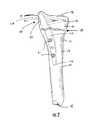
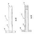
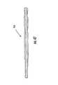
- FIG. 3is a side elevation view of a fixation member of the intramedullary fixation assembly of FIG. 1 ;
- FIG. 4is another side elevation view of a fixation member of the intramedullary fixation assembly of FIG. 1 ;
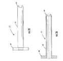
- FIG. 5is another side elevation view of a fixation member of the intramedullary fixation assembly of FIG. 1 ;
- FIG. 6is another side elevation view of a fixation member of the intramedullary fixation assembly of FIG. 1 ;
- FIG. 7is a sectional view of the fixation member of FIG. 6 ;
- FIG. 8is a sectional view of the fixation member of FIG. 6 ;
- FIG. 9is a sectional view of the fixation member of FIG. 6 ;
- FIG. 10is a sectional view of the fixation member of FIG. 6 ;
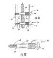
- FIG. 11is a sectional view of a portion of the fixation member and a pair of bone fasteners of the intramedullary fixation assembly of FIG. 1 ;
- FIG. 12is a sectional view of one of the bone fasteners shown in FIG. 11 ;
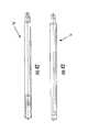
- FIG. 13is a side elevation view of a fixation member of another embodiment of the present invention, including a stem extending from one of its ends;
- FIG. 14is another side elevation view of the fixation member of FIG. 13 ;
- FIG. 15is a plan view of a head end of one of the bone fasteners shown in FIG. 11 ;
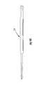
- FIG. 16is a side elevation view of the bone fastener shown in FIG. 15 ;
- FIG. 17is a sectional view of the bone fastener shown in FIG. 15 ;
- FIG. 18is a plan view of a head of a k-wire for use as a bone fastener in another embodiment of an intramedullary fixation assembly of the present invention.
- FIG. 19is a sectional view of the k-wire shown in FIG. 18 ;
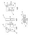
- FIG. 20is a side elevation view of an outrigger frame of a guide assembly of another embodiment of the present invention shown in FIG. 53 ;
- FIG. 21is a plan view of the outrigger frame of FIG. 20 ;
- FIG. 22is another side elevation view of the outrigger frame of FIG. 20 ;
- FIG. 23is plan view of a targeting guide of the guide assembly of the present invention shown in FIG. 53 ;
- FIG. 24is a side elevation view of the targeting guide of FIG. 23 ;
- FIG. 25is another plan view of the targeting guide of FIG. 23 ;
- FIG. 26is a sectional view of the targeting guide of FIG. 25 ;
- FIGS. 27-30are various views of the targeting guide of another embodiment of the present invention.
- FIG. 31is a side elevation view of a screw-in drill guide which is part of the outrigger frame of FIG. 20 ;
- FIG. 32is a sectional view of the screw-in drill guide of FIG. 31 ;
- FIG. 33is a side elevation view of a drill guide of another embodiment of the present invention.
- FIG. 34is a sectional view of the drill guide of FIG. 33 ;
- FIG. 35is a side elevation view of a screw guide of a guide assembly as shown in FIG. 59 ;
- FIG. 36is a sectional view of the screw guide of FIG. 35 ;
- FIG. 37is a side elevation view of guide member of the outrigger frame shown in FIG. 20 ;
- FIG. 38is a sectional view of the guide member of FIG. 37 ;
- FIGS. 39 and 40show a perspective view of attachment of a set of four prongs on the guide member of FIG. 37 within a set of four recesses defined in an end of the fixation member shown in FIG. 6 ;
- FIG. 41is an enlarged view of the prongs and recesses of FIG. 39 forming an interference fit
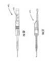
- FIGS. 42 and 43show a side elevation view of a fastener driving drill bit of another embodiment of the present invention.
- FIG. 44is a side elevation of a drill bit of another embodiment of the present invention.
- FIG. 45is a plan view of a hand driver of another embodiment of the present invention.
- FIG. 46is a side elevation view of the hand driver of FIG. 45 ;
- FIG. 47is a sectional view of a cannulated drill bit of another embodiment of the present invention.
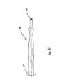
- FIG. 48is a side elevation view of a trialing broach assembly of another embodiment of the present invention.
- FIG. 49is a side elevation of a handle of the trialing broach assembly shown in FIG. 48 ;
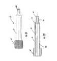
- FIG. 50is a side elevation view of a depth indicator of another embodiment of the present invention.
- FIG. 51is a sectional view of the depth indicator of FIG. 50 ;
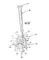
- FIG. 52is a perspective view of the trialing broach assembly of FIG. 48 show inserted into a long bone
- FIG. 53is a perspective view of the fixation member of FIG. 3 connected to the guide assembly of the present invention.
- FIG. 54is a perspective view of the fixation member and guide assembly of FIG. 53 , wherein the fixation member has been positioned in the medullary canal of the fractured long bone;
- FIG. 55is a perspective view of the guide assembly and fixation member shown in FIG. 54 , wherein the guide assembly is guiding drilling through an opening in the fixation member and into the long bone;
- FIG. 56is a perspective view of the guide assembly and fixation member shown in FIG. 54 , wherein drilling is being guided through another opening in the fixation member;
- FIG. 57is a perspective view of the guide assembly and fixation member of FIG. 54 guiding placement of a bone fastener, such as the bone fasteners shown in FIGS. 11 and 12 , through the bone and the opening in the fixation member;
- a bone fastenersuch as the bone fasteners shown in FIGS. 11 and 12
- FIG. 58is a perspective view of placement of another bone fastener using the assemblies of FIG. 57 ;
- FIG. 59is a perspective view of placement of yet another bone fastener using the assemblies of FIG. 57 ;
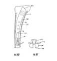
- FIG. 60is a sectional view of a long bone and a fixation member of another embodiment of the present invention, wherein the fixation member includes a split tail;
- FIG. 61is a sectional view of a bone fastener of another embodiment of the present invention positioned within the split tail of the fixation member of FIG. 60 ;
- FIG. 62is a sectional view of a long bone and a fixation member of another embodiment of the present invention, wherein the fixation member includes a split tail;
- FIG. 63is a sectional view of the long bone and fixation member of FIG. 62 wherein one arm of the split tail is threaded to allow splaying of the split tail
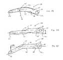
- FIG. 64is a side elevation view of an impactor having a U-shaped end and fixation member defining U-shaped slots for receiving the end of the impactor in another embodiment of the present invention
- FIG. 65is a sectional view of the U-shaped impactor and slot of FIG. 64 ;
- FIGS. 66-72show assorted views of an S-shaped, positive fit connection between a guide assembly and fixation member of another embodiment of the present invention.
- FIG. 73is a side elevation view of a fixation member of another embodiment of the present invention having a bow tilt
- FIG. 74is a side elevation view of a fixation member of another embodiment of the present invention having a linear offset
- FIG. 75is a side elevation view of a fixation member of another embodiment of the present invention having an angular bend.
- FIGS. 1 and 2An intramedullary fixation assembly 10 of one embodiment of the present invention is shown installed in a long bone 11 of a patient in FIGS. 1 and 2 .
- the long bonecould be any of a number of long bones, such as a femur, tibia, radius or humerus.
- the fixation assembly 10is most suited to repairing fractures of the long bone 11 wherein the fracture is at one end near an articular cartilage surface 12 and wherein it is desired to leave the articular surface undisrupted during the repair.
- the long boneincludes a widened end 13 that supports the articular cartilage surface which tapers to a more narrow shaft 14 .
- a medullary canal 15Extending within the shaft 14 and a portion of the widened end 13 is a medullary canal 15 .
- every type of long bonewill have the afore-described characteristics, such as the shaft 14 being relatively narrower than the end 13 .
- the proportional geometry of the different long boneswill vary due to their biology and function.
- the terms “different long bones,” “various long bones,” and other, related termsdo not refer to the same type of long bone in different people, but different types of long bones, such as a femur versus a tibia, or radius, or humerus.
- the intramedullary fixation assemblycould be used to repair somewhat more complex fractures, but is shown being used to repair a first bone fragment 16 separated from a second bone fragment 17 by a single fracture line 18 .
- a side aperture 19is defined in a lateral surface of the widened end 13 , subjacent the articular cartilage surface 12 , to allow insertion of the intramedullary fixation assembly 10 .
- the intramedullary fixation assembly 10includes an elongate fixation member 20 and a plurality of fasteners 21 that extend through the elongate fixation member to attach it to the long bone 11 above and below the fracture line 18 and thereby reduce the fracture, for example as shown in FIGS. 1 and 2 .
- the elongate fixation member 20preferably, when positioned within the medullary canal 15 of the long bone 11 (regardless of its type), has a first end 22 positioned adjacent the side aperture 19 . Extending from the first end, through the rest of the aperture and into the medullary canal 15 of the first bone fragment 16 , is a curved body 24 (shown in broken lines in FIGS. 1 and 2 ) of the fixation member 20 .
- the curved body 24extends to a second end 23 which is positioned within the medullary canal 15 of the second bone fragment 17 .
- a radius of curvature of the curved body 24is selected to promote smooth insertion of the curved body through the side aperture 19 and into the medullary canal 15 despite differences in the width of the widened end 13 and the shaft 14 and medullary canal 15 between the various types of long bone 11 .
- FIGS. 3-14one embodiment of the fixation member 20 of the present invention is shown in FIGS. 3-14 .
- the first end 22 of the fixation member 20has two intersecting flat surfaces, including an exposed first end surface 27 that is accessible through the side aperture 19 and an adjacent first end surface 28 that is at a right angle to the exposed surface, as shown in FIG. 4 .
- the second end 23 of the fixation member 20has a rounded profile with a radius of about 0.08 inches, as shown in FIG. 4 , and edges rounded to about a 0.06 inch radius, as shown in FIG. 5 .
- the curved body 24 of the fixation member 20includes a convex side 29 and a concave side 30 that are on opposite sides of the curved body.
- the sideshave radii of curvature with a similar center, but the center of the convex side changes so that the sides converge in a slight taper as they extend to the second end 23 , as shown in FIG. 4 .
- the radius of curvature of the concave side 30is about 3.12 inches and the radius of curvature of the convex side 29 is about 3.36 inches near the first end 22 when measured from a first center 31 positioned about 2.14 inches from the plane of the adjacent first end surface 28 and about 2.47 inches from the plane of the exposed first end surface 27 .
- the radius of curvature of the convex side 29shifts to about 2.68 inches at a second center 32 that is positioned about 1.89 inches from the plane of the adjacent first end surface 28 and about 1.5 inches from the plane of the exposed first end surface 27 .
- this shiftproduces the taper near the second end 23 of the fixation member 20 .
- maintaining a constant radius of curvature near the first end 22 of the curved body 24allows for different sized and different types of long bones to be accommodated merely by extending the arc further to produce a greater “hook.” This overcomes the increase in not only the length of the long bone 11 , but also the increase in distance between widened end 13 and width of the medullary canal 15 , facilitating its use on different and larger types of long bones. If measured from the centerline of the curved body 24 , the radius of curvature can actually be constant between the sides 29 , 30 and the ends 22 , 23 regardless of the amount of taper.
- This radius of curvaturecan also be maintained while the arc length of the curved body 24 is extended to account for increased length of the long bone 11 and increased offset between the side aperture 19 and the position of the medullary canal 15 .
- an entire kit of fixation memberscould have the same radius of curvature but be usable in different types and lengths of long bones.
- a second pair of opposite, side surfaces 33extend between the convex side 29 and concave side 30 , as shown in FIGS. 3 and 5 . Similar to the convex side 29 and concave side 30 , the side surfaces 33 taper slightly toward each other as they extend from the first end 22 to the second end 23 of the curved body 24 . However, the side surfaces 33 in the illustrated embodiment are relatively planar, as opposed to the curved shape of the sides 29 , 30 . Advantageously, the taper of the sides 29 , 30 , 33 , the continuous curve of the curved body 24 between the ends 22 , 23 and the rounded profile of the second end 23 help to facilitate insertion through the side aperture 19 and into the medullary canal 15 .
- continuousdiffers from “constant” in reference to curvature herein in that a continuous curvature is not necessarily a constant curvature.
- radii of curvaturewithin about the ranges cited above, with variations of about 1.5 to 5 inches, allow the fixation member 20 to be employed in different (preferably human) long bones with only variations in the overall length of the fixation member.
- the fixation member 20there may be some adaptations of the fixation member 20 beyond extension of the arc length, such as through the application of a tilt.
- the tiltwould generally not be in the curvature defined by the convex and concave sides 29 , 30 to accommodate curvature in different long bones.
- a volar tiltmay be used to accommodate the volar tilt in the saggital plane of the human radius.
- volar tiltfacilitates better filling of the medullary canal of the distal radius and can improve stabilization of the fixation member 20 .
- the tiltcan be accomplished, for example, through the use of a radial bow, as shown in FIG. 73 , a linear offset, as shown in FIG. 74 , or an angular bend, as shown in FIG. 75 .
- the radial bowranges from about 4 to 8 inches (100 to 200 mm) of curvature.
- the linear offsetis about 2 to 5 mm and the angular bend is about a 10° to 20° angle.
- a plurality of fastener openingsare defined in the fixation member. These fastener openings include a side aperture accessible fastener opening 34 , a pair of fastener openings 35 extending between the curved convex side 29 and concave side 30 , and fastener openings 36 extending between the side surfaces 33 .
- the fastener opening 34extends from the exposed first end surface 27 (which is accessible through the side aperture 19 when the fixation member 20 is installed) through a portion of the curved body 24 and to the convex side 29 , as shown in FIGS. 4 and 5 .
- the fastener opening 34includes a guide portion 38 and a fastener head portion 39 that is generally more narrow than the guide portion.
- Both of the portionsare threaded, as shown in FIGS. 7 and 8 , to facilitate a secure fit by the fasteners 21 and various installation devices, as will be described in more detail below.
- the pair of fastener openings 35which extend between the sides 29 , 30 extend through the curved body 24 nearer the first end 22 so as to be within the first bone fragment 16 , as shown in FIG. 5 .
- Each of the fastener openingsalso has a threaded fastener portion 39 similar to the fastener opening 34 , but a non-threaded guide portion 38 , as shown in FIGS. 9 and 10 .
- These fastener openings 35extend at different, divergent angles than each other and the orientation of the fastener opening 34 which is relatively orthogonal with respect to the exposed first end surface 27 and the convex side 29 , as shown in FIG. 3 .
- the fastener openings of the present invention(such as the fastener openings 35 ) need not all be aligned with the axis of the fixation member.
- angles of the fastener openings 34 , 35may be configured so that the fasteners extend subjacent to the articular cartilage for improved fixation. Generally, this will require the fastener openings 34 , 35 to extend at some acute angle, such as an angle between about 50° and 85° (depending on the origin of the fastener opening), and preferably about 60° to 70°, with respect to the fixation member body. Basically, these angles are to match the inclination angle of the articular surface so as to provide a buttress effect for the articular cartilage.
- the ulnar inclination angle of the articular cartilage on the radiusis about 23° (resulting in a 67° fastener opening angle).
- the buttress effectis also improved by the sub-chondral placement of the first end surface 28 that is adjacent and at a right angle with respect to the exposed first end surface 27 so as to underlie the articular cartilage.
- three fastener openings 36are defined in the curved body 24 at a position nearer the second end 23 of the fixation member 20 .
- the two outer ones of the fastener openings 36are configured to receive threaded fasteners 21 , similar to the fastener openings 34 , 35 , but the center one of the fastener openings 36 is configured to receive a relatively smaller diameter k-wire fastener 41 , as shown in FIG. 6 .
- the larger of the fastener openings 36are not threaded to allow a slip fit of the threaded fasteners 21 without damaging the threads, as will be described below.
- the threaded fasteners 21are shown in greater detail by FIGS. 15-17 and the k-wire fastener 41 by FIGS. 18 and 19 .
- Each of the fasteners 21 , 41is shown as being driven by a Phillips-type, or cruciform-type, head ( FIGS. 15, 17 and 18 ), but may be configured for mating with a driver in any number of ways, such as with an Allan-type head or flat head.
- Each of the illustrated threaded fasteners 21includes a head 42 , a threaded shaft 43 , a non-threaded shaft portion 45 and a bone-securing end 44 , as shown in FIG. 16 .
- each of the threaded fasteners 21has a larger diameter than its shaft 43 , so as to prevent the threaded fastener from passing through tapped openings in the first layer of cortical bone.
- the diameter of the head 42is still small enough to pass through a screw guide 51 , or other guide, positioned by the guide assembly 50 within the guide portion 38 , as will be described in more detail below.
- the headWhen the threaded fasteners 21 are inserted through the openings 34 , 35 and into the first bone fragment 16 , the head is configured to reside in the guide portion 38 , the threaded shaft 43 in the threaded fastener portion 39 and the bone-securing layer is configured to attach to the distant layer of cortical bone opposite the side aperture 19 and subjacent the articular cartilage surface 12 , as shown in FIGS. 1 and 2 .
- the threaded shaft 43When inserted through the openings 36 and into the second bone fragment 17 , the threaded shaft 43 is configured to attach to the first layer of cortical bone, the non-threaded shaft portion 45 is configured to reside in the openings 36 in a slip fit and the bone-securing end 44 is configured to attach to the distant layer of cortical bone opposite the first layer of cortical bone, as shown in FIG. 11 .
- the fastener head 42is configured to abut the first layer of cortical bone, and may have a rounded shape to minimize irritation of the overlying tissues, as shown in FIG. 12 .
- the threaded fasteners 21when used in the openings 36 , the threaded fasteners 21 become bi-cortical screws, firmly attaching to two layers of cortical bone.
- the non-threaded shaft 45may include a chamfer 63 to help locate the screw in the openings 36 as it is advanced through the fixation member 20 .
- the bone-securing end 44preferably has threads and an outer diameter that is smaller than the minimum, trough diameter of the threads on the threaded shaft 43 and the diameter of the un-threaded shaft portion to prevent the bone-securing end from locking up or fretting the threads when passing through the fastener portion 39 .
- a neck 46 on each of the threaded fasteners 21also prevents lockup by providing space between the threaded fastener shaft 43 and fastener head 42 , as shown in FIGS. 16 and 17 . As shown in FIG.
- the k-wire fastener 41also includes a fastener head 42 , a neck 46 , a threaded shaft 43 and a non-threaded shaft portion 45 , but its bone securing end 44 is not threaded for easier insertion as the first fastener.
- the threaded shaft 43 of one of the threaded or k-wire fasteners 21 , 41mates with the threaded fastener portion 39 of its respective one of the fastener openings 34 , 35 and 36 and the bone-securing end 44 extends into the long bone 11 for a secure fit, as shown in FIGS. 1 and 2 .
- fastenerstwo types are described herein that are preferred, other types of fasteners may also be employed, including other types of wires, screws, etc., and still be within the purview of the present invention as long as some portion of the fastener secures itself to the fixation member 20 and another portion to the long bone 11 .
- FIGS. 20-30illustrate the guide assembly 50 of the present invention that is used to position the screw guide 51 , a screw-in drill guide 52 and a plurality of other drill guides 53 , shown in FIGS. 31-36 .
- the guide assembly 50includes an outrigger frame 54 having a curved, hook-shaped body 55 including a first end 56 for positioning fasteners 21 within the first end 22 of the fixation member 20 and the first bone fragment 16 , and a second end 57 for positioning fasteners within the second end 23 of the fixation member and the second bone fragment 17 , as shown in FIGS. 20-22 .
- the outrigger frame 54also includes a guide member 58 that has a truncated pyramid shape and extends from a flat surface of the first end 56 of the hook-shaped body 55 , as shown in FIGS. 20 and 22 .
- the guide member 58tapers as it extends outward from the hook-shaped body and ends in four prongs 59 , as shown in FIGS. 37-40 .
- Each of the prongs 59has a rounded shape with opposing edge surfaces 60 angled toward each other (i.e., they are generally converging) as they extend outwards from the end of the truncated pyramid shape.
- the guide member 58 and its subjacent portion of the hook-shaped body 55define a stepped opening 61 , as shown in FIG. 38 , that is sized to receive the screw-in drill guide 52 (shown in FIGS. 31 and 32 ).
- the stepped opening 61includes shoulders 62 that prevent the passage of the screw-in drill guide 52 .
- the screw-in drill guide 52includes a burled knob 65 , an elongate shaft 66 , a tapered shoulder 67 and a threaded tip 68 .
- the burled knobprovides 65 a gripping surface for tightening the screw-in drill guide 52 and its relatively large diameter acts as a stop against passage of the screw-in drill guide through the stepped opening 61 when inserted therein and tightened.
- the elongate shaft 66extends from the burled knob and tapers at the tapered shoulder 67 down to the diameter of the threaded tip 68 . This shape allows passage of the threaded tip through and out of the stepped opening 61 so that the threaded tip 68 can be advanced into the threads of the guide portion 38 of the fastener opening 34 .
- a guide openingthat extends from the burled knob 52 through to the threaded tip 68 and includes a large diameter portion 70 that tapers to a small diameter portion 71 near the threaded tip, as shown in FIG. 32 .
- This change in diameterhelps to concentrically center the fasteners 21 as they are advanced through the screw-in drill guide 52 and into the fastener opening 34 defined in the fixation member 20 , as will be described below.
- the guide member 58 and its prongs 59which are also spaced in a cruciform or cross pattern similar to the indentations 40 , are advanced into the indentations, as shown in FIG. 40 .
- the cruciform patterncombined with the positive fit, firmly locks the outrigger frame 54 to the fixation member 20 before and during guidance of insertion of the various fasteners 21 , 41 .
- This firm attachmentguards against relative motion of the guide assembly 50 with respect to the fixation member 20 , so that misalignment of the guides 51 , 52 , 53 is reduced even with just a single point of attachment of the guide assembly to the fixation member.
- the cruciform shape and positive fitare particularly effective at restricting rotation between the guide assembly and fixation member, which can be a problem due to the relative length and cantilevered configuration of the guide assembly and fixation member, especially on the larger long bones such as the tibia and femur. It should be noted, however, that the positive fit of the prongs 59 in the concave indentations 40 could be accomplished in other ways, such as by having the indentations on the guide member 58 instead of the exposed first end surface 27 of the fixation member 20 .
- the positive or press fitmay be implemented or facilitated, as shown for example in FIG. 41 , by slightly over-sizing a male fitting portion (e.g., the prongs 59 ) with respect to a female portion (e.g., the concave indentations 40 ) so that the angled opposing surfaces (e.g., converging edge surfaces 60 ) are in contact and the tip of the male portion, and other remaining flat surfaces have minimal contact to allow the angled surfaces to wedge into each other.
- a male fitting portione.g., the prongs 59
- a female portione.g., the concave indentations 40
- the first end 56further supports two screw guides 51 that are integrally connected to, and extend from, the first end of the hook-shaped body, as shown in FIGS. 20-22 .
- These screw guides 51are cylindrical tubes that define openings extending therethrough and are oriented so as to have an axis collinear and aligned with the axes of the of the pair of openings 35 defined in the curved body 24 of the fixation member 20 .
- the screw guides 51are oriented so that the fasteners 21 extend at an angle into the first bone fragment 16 right below the articular cartilage surface 12 , as shown in FIGS. 1 and 2 .
- the first end 56also includes a handle mount 37 defining a threaded opening.
- the channel member 72has an elongate rectangular shape, as shown by FIGS. 21 and 22 , and includes a pair of channel arms 73 extending away and along the length of the rectangular shape, as shown in FIGS. 20 and 21 .
- Each of the armsdefines an angled surface 74 extending toward the other one of the arms and the arms are spaced from each other and parallel so as to define a channel. Extending into the channel defined between the arms 73 is a stop 75 .
- the second end 57 and the channel member 72define a locking member opening 76 that extends into the channel between the arms 73 .
- the locking member opening 76is sized and includes threads to receive advancement of a locking member 77 , as shown in FIGS. 20 and 22 .
- the locking memberincludes its own burled knob 78 to facilitate its advancement and also has a frusto-conical shaped distal locking tip 79 that extends out of the locking member opening 76 and into the channel between the arms 73 when the locking member 77 is fully advanced, as shown in FIGS. 20 and 21 .
- a targeting guide 80(as shown in FIGS. 23-26 ) that is configured to support and orient the drill guides 53 and screw guides 51 that are used to guide insertion of the fasteners 21 , 41 through the fixation member 20 and into the long bone 11 .
- Different targeting guides 80can also be used for different sized fixation members 20 (e.g., as shown in FIGS. 27-30 ), and can be employed in right and left handed configurations depending on the type of long bone being treated and the orientation of the side aperture 19 .
- the targeting guideincludes a guide portion 81 and a slide attachment portion 82 .
- the guide portion 81defines a plurality of guide openings 83 sized for the passage of screw guides 51 or drill guides 53 sized for threaded fasteners 21 or for the smaller diameter k-wire fasteners 41 .
- the guide openings 83are positioned along an arc (as shown in FIGS. 23 and 25 ) to correspond to the placement of the openings 36 through the side surfaces 33 of the curved body 24 so as to guide the fasteners 21 , 41 into the openings 36 .
- one of the smaller diameter openings 83may be placed to orient insertion of one of the k-wire fasteners 41 external to the fixation member 20 to avoid additional holes in the fixation member and provide for temporary securing of the guide assembly 50 .
- the slide attachment portion 82is generally rectangular and defines a pair of slots 84 that extend to one edge of the side attachment portion. As is shown in FIG. 26 , these slots are defined by a pair of angled, opposing surfaces 85 . In addition, at about a midpoint along one edge of the slide attachment portion 82 is defined a circular centering divot 86 with sloped sides, as shown in FIGS. 24 and 26 .
- the pair of slots 84 of the slide attachment portion 82are inserted between the channel arms 73 until approximately at the end of travel of the slots. Then, the locking member 77 is advanced in the opening 76 until the locking tip 79 enters the centering divot 86 .
- the sloped sides of the centering divot 86interact with the sloped edges of the locking tip 79 which forces the targeting guide 80 to center and forms a relatively tight, positive fit.
- each of the screw and drill guides 51 , 53include a grip flange 48 at one end of an elongate shaft 49 that defines teeth 47 at its other end.
- a guide shaft openingthat tapers from a wider to narrower diameter near the teeth 47 , as shown in FIG. 34 .
- the elongate shaft 49 of the screw guide 51also defines a guide shaft, but this guide shaft has a constant diameter because, as described above, the fasteners 21 , 41 are restrained by the structure of the fixation member 20 from advancing too far.
- the drill guides 53are first inserted into the guide openings 83 of the guide portion 81 of the targeting guide and are advanced until the teeth 47 contact skin or bone (so as to prevent rotation of the guides).
- a pilot holeis drilled using the drill bit 90 guided by the drill guides 53 .
- the drill guides 53are removed and screw guides 51 are inserted in the guide openings 83 until the teeth 47 contact skin or bone.
- the selected one of the threaded or k-wire fasteners 21 , 41are advanced at the end of a driver 91 (as shown in FIGS. 42 and 43 ) until penetrating the fixation member 20 through one of the openings 36 and into the long bone 11 (in this case the second bone fragment 17 ).
- the driver 91 or drill bit 90may be advanced using power or by hand, such as by a hand driver 92 , as shown in FIGS. 45 and 46 .
- a k-wireis inserted into a lateral side of the widened end 13 of the long bone 11 subjacent the articular cartilage surface 12 and used to guide a cannulated drill bit 94 , as shown in FIG. 47 .
- the cannulated drill bitclears the side aperture 19 and a conventional bone awl (not shown) is used to open the medullary canal 15 of cancellous bone.
- a trialing broach 95is pushed, twisted, hammered, etc., into the long bone 11 through the side aperture 19 to approximate the size of the fixation member 20 .
- the trialing broachincludes a handle 98 and an awl point 99 .
- the handle 98includes a head 100 that facilitates gripping and hammering at one end and a threaded connector 101 at the other end, as shown in FIG. 49 .
- This threaded connectoris similar to the threaded tip 68 of the screw-in drill guide allowing the exchange of the awl point 99 with other awl points of different sizes, each having threaded opening at one end similar to the threaded opening 34 on the fixation member 20 .
- the awl point 99has some type of teeth or cutter (as shown symbolically by the cross-hatch pattern 96 ) to aid in bone removal and sizing.
- the trialing broaches 95may eliminate the need for many awls and cutting tools. However, other conventional tools, such as reamers and awls could also be employed to clear bone.
- Each of the broaches 95may also include a depth indicator, such as the notch 97 shown in FIG. 48 , that indicates the correct depth for that size of fixation member 20 .
- the depth indicator or notch 97may include the use of fluorescent paint so as to be easily visually detectable.
- an appropriately sized fixation member 20is selected based on the various above-described measurements.
- the handle 98 of the trialing broach 95is removed from the awl point 99 and attached to the threaded opening defined in the handle mount 37 via the threaded connector 101 on the handle, as shown in FIG. 53 .
- the outrigger frame 54 of the guide assembly 50is attached to the fixation member.
- the screw-in drill guide 52is extended through the stepped opening 61 of the guide member 58 and its threaded tip 68 is advanced into the threaded opening 34 of the guide assembly.
- This assemblymates the prongs 59 with the concave indentations 40 , thereby locking out micro-motion and rotation between the outrigger frame 54 and the fixation member 20 , as shown in FIGS. 39 and 40 .
- the targeting guide 80is attached to the channel member 72 by sliding the channel arms 73 within the pair of slots 84 on the guide portion 81 until the targeting guide is against the stop 75 . Then, the locking member 77 is advanced in the opening 76 until the locking tip 79 enters the centering divot 86 .
- the sloped sides of the centering divot 86interact with the sloped edges of the locking tip 79 which forces the targeting guide 80 to center and forms a relatively tight, positive fit. Once the locking tip 79 bottoms within the centering divot 86 , further advancement of the locking tip pushes the angled, opposing surfaces 85 of the slots against the angled surfaces 74 of the channel arms 73 .
- the handle 98 and guide assembly 50are then used to slide the fixation member 20 , as facilitated by the tapered ends 22 , 23 through the side aperture 19 and into the medullary canal 15 , as shown in FIG. 54 .
- the handle 98is then unscrewed from the handle mount 37 .
- the fixation member 20may include radio-lucent targeting indicia to aid in positioning of the fixation member and guide assembly 50 .
- the length of the handle 98allows for easy readjustment of the position of the fixation member 20 .
- Smaller guide openings 83 on the targeting guide 80are used to place a temporary k-wire fastener 41 , such as by using the smaller opening falling outside of the fixation member 20 . This allows for a temporary fixation into both the first and second bone fragments 16 , 17 .
- the drill guides 53are placed into the appropriately sized openings 83 .
- the dual-diameter drill bit 90is advanced into the drill guides 53 , the screw guides 51 connected to the hook-shaped body 55 (if necessary) and the guide member 58 to form pilot holes in the long bone 11 , as shown in FIGS. 55 and 56 .
- the depth of these holesare then tested using a depth gauge 102 , as shown in FIGS. 50 and 51 .
- the depth gauge 102may also employ fluorescent paint to ensure clear readability, such as on measurement numbers and hash marks 103 .
- the depth measurementsfacilitate selection of fasteners 21 , 41 of the appropriate length.
- the drilled holesare then tapped (not shown) to prepare them for insertion of threaded fasteners 21 .
- the drill guides 53are replaced with the screw guides 51 (if necessary) and the threaded fasteners 21 are advanced through the aligned openings 34 , 35 , 36 in the fixation member 20 and the long bone 11 so as to connect the bone fragments 16 , 17 , as shown in FIGS. 57, 58 and 59 .
- the guide assembly 50 and handle 98can then be removed by removal of the temporary k-wire fastener 41 and the screw-in drill guide 52 .
- the fixation member 20 of the intramedullary fixation assembly 10may include a tail portion 105 extending from, or as part of, the second end 23 , as shown in FIGS. 13 and 14 .
- the tail portionhas a much smaller diameter or thickness than the curved body 24 and is relatively straight to conform to the straightness of the shaft 14 of the long bone 11 .
- the tail portionin some circumstances can improve the tightness of fit of the fixation member 20 in the second bone fragment 17 with its extra length.
- Another option for improving the fit within the second bone fragmentis to employ the use of a split tail 106 , as shown in FIG. 60 .
- the split taildefines a slot 107 that separates the split tail into two spaced arms that are drawn against the cortical wall and urged apart as a tapered screw 108 is advanced through the slot, as shown in FIG. 61 .
- the slot 107 of the split tail 106may also be placed in an opposite plane with a threaded opening in one of the arms so that passage of a standard screw therethrough pushes the arms apart for additional stability, as shown in FIGS. 60 and 61 .
- the split tail portion 105has a spring bias due to construction from a flexible material, such as a metal material, and wherein the split tail is defined by a coronal slot.
- the fixation member 20may be shaped to accommodate a driving handle 110 by having defined in its first end 22 a pair of U-shaped slots 112 on either side of the fixation member, as shown in FIGS. 62 and 63 .
- the driving handle 110includes a horseshoe or U-shaped impact end 111 that straddles the fixation member 20 , inserting into the U-shaped slots 112 wherein the rounded shapes avoid eccentric loading while the fixation member is being driven into the medullary canal 15 .
- Clearancemay also be defined in the guide assembly 50 for the impact end 111 to allow the guide assembly to remain attached during driving.
- the slots 112may also be defined in the guide assembly 50 for driving the fixation member 20 via its attachment to the guide assembly.
- the guide member 58may include a pair of S-curved fittings 113 , as shown in FIGS. 64, 65, 66 and 67 , that are configured to mate in a positive fit with S-curved slots 114 defined on the first end 22 of the fixation member 20 , as shown in FIGS. 68, 69 and 70 .
- the inventionhas many advantages.
- the inventionhas many attributes that facilitate its use for different types of human long bone 11 wherein the fixation device extends from the metaphysis to the diaphysis (via the positioning of the side aperture 19 ), but not through the epiphysis, so as to avoid damaging the articular cartilage.
- Maintaining a constant radius of curvature near the first end 22 of the curved body 24allows for different sized long bones to be accommodated merely by extending the arc further to produce a greater “hook.” This overcomes the increase in not only the length of the long bone 11 , but also the increase in distance between widened end 13 and width of the medullary canal, facilitating its use on different and larger types of long bones.
- use of a radius of curvature in the range of 1.5 to 5 inchesfacilitates use with different types of long bone 11 , especially when the curved body 24 curves continuously along its length and the ends 22 , 23 are tapered for easy insertion.
- the use of a cruciform shape and positive fit or wedge effect used for the concave indentations 40 and the prongs 59provides rotational and translational stability of the fixation member 20 when attached to the guide assembly 50 .
- the positive fit or wedge effectoperates to center and reduce micro-motion between the targeting guide 80 and the rest of the guide assembly 50 .
- Use of the positive fit of the channel arms 73 , the locking tip 79 , the slots 84 and the centering divot 86is capable of achieving an accuracy in the range of one hundredths of an inch.
- the improved positioning from the positive fitallows the single guide assembly 50 to facilitate placement of all of the fasteners, eliminating the need to use multiple assemblies and select openings via X-rays or other visual or manual method.
- fixation member 20 and guide assembly 50Use of k-wire fasteners 41 and k-wire sized guide openings 83 and openings 36 in the curved body 24 of the fixation member 20 allow the fixation member 20 and guide assembly 50 to be temporarily fixed to the long bone 11 after reduction of the fracture. This allows the health care personnel to use both hands to insert the remaining fasteners 21 , 41 .
- the cannulated, screw-in drill guide 52 with its internal guide shaftallows for insertion of fasteners 21 , 41 into both the first and second bone fragments 16 , 17 without removal or reconfiguration of the guide assembly 50 .
- the stop 75prevents mounting of a left oriented targeting guide 80 to a left-handed outrigger frame 54 and vice-versa for a right handed outrigger frame.
- the dual diameters 70 , 71 of the drill guides 53ensure concentricity of the dual-diameter drill bit 90 .
- the fixation member 20may have defined on its outer surface grooves or texture (similar to the awl point 99 ) that facilitates a tight fit in the medullary canal 15 or can hold biologic or pharmacologic materials to facilitate bone ingrowth. Therefore, it is to be understood that the inventions are not to be limited to the specific embodiments disclosed and that modifications and other embodiments are intended to be included within the scope of the appended claims. Although specific terms are employed herein, they are used in a generic and descriptive sense only and not for purposes of limitation.
Landscapes
- Health & Medical Sciences (AREA)
- Surgery (AREA)
- Life Sciences & Earth Sciences (AREA)
- Orthopedic Medicine & Surgery (AREA)
- Biomedical Technology (AREA)
- Public Health (AREA)
- Veterinary Medicine (AREA)
- Engineering & Computer Science (AREA)
- Nuclear Medicine, Radiotherapy & Molecular Imaging (AREA)
- Heart & Thoracic Surgery (AREA)
- Medical Informatics (AREA)
- Molecular Biology (AREA)
- Animal Behavior & Ethology (AREA)
- General Health & Medical Sciences (AREA)
- Dentistry (AREA)
- Oral & Maxillofacial Surgery (AREA)
- Neurology (AREA)
- Surgical Instruments (AREA)
Abstract
Description
Claims (25)
Priority Applications (1)
| Application Number | Priority Date | Filing Date | Title |
|---|---|---|---|
| US12/389,137US9451971B2 (en) | 2004-07-15 | 2009-02-19 | Intramedullary fixation assembly and devices and methods for installing the same |
Applications Claiming Priority (3)
| Application Number | Priority Date | Filing Date | Title |
|---|---|---|---|
| US10/891,737US20060015101A1 (en) | 2004-07-15 | 2004-07-15 | Intramedullary fixation assembly and devices and methods for installing the same |
| US11/948,189US20080091203A1 (en) | 2004-07-15 | 2007-11-30 | Intramedullary fixation assembly and devices and methods for installing the same |
| US12/389,137US9451971B2 (en) | 2004-07-15 | 2009-02-19 | Intramedullary fixation assembly and devices and methods for installing the same |
Related Parent Applications (1)
| Application Number | Title | Priority Date | Filing Date |
|---|---|---|---|
| US11/948,189ContinuationUS20080091203A1 (en) | 2004-07-15 | 2007-11-30 | Intramedullary fixation assembly and devices and methods for installing the same |
Publications (2)
| Publication Number | Publication Date |
|---|---|
| US20090157079A1 US20090157079A1 (en) | 2009-06-18 |
| US9451971B2true US9451971B2 (en) | 2016-09-27 |
Family
ID=35600433
Family Applications (3)
| Application Number | Title | Priority Date | Filing Date |
|---|---|---|---|
| US10/891,737AbandonedUS20060015101A1 (en) | 2004-07-15 | 2004-07-15 | Intramedullary fixation assembly and devices and methods for installing the same |
| US11/948,189AbandonedUS20080091203A1 (en) | 2004-07-15 | 2007-11-30 | Intramedullary fixation assembly and devices and methods for installing the same |
| US12/389,137Expired - LifetimeUS9451971B2 (en) | 2004-07-15 | 2009-02-19 | Intramedullary fixation assembly and devices and methods for installing the same |
Family Applications Before (2)
| Application Number | Title | Priority Date | Filing Date |
|---|---|---|---|
| US10/891,737AbandonedUS20060015101A1 (en) | 2004-07-15 | 2004-07-15 | Intramedullary fixation assembly and devices and methods for installing the same |
| US11/948,189AbandonedUS20080091203A1 (en) | 2004-07-15 | 2007-11-30 | Intramedullary fixation assembly and devices and methods for installing the same |
Country Status (1)
| Country | Link |
|---|---|
| US (3) | US20060015101A1 (en) |
Cited By (2)
| Publication number | Priority date | Publication date | Assignee | Title |
|---|---|---|---|---|
| US10610270B2 (en) | 2018-01-15 | 2020-04-07 | Glw, Inc. | Hybrid intramedullary rods |
| US11202663B2 (en) | 2019-02-13 | 2021-12-21 | Globus Medical, Inc. | Proximal humeral stabilization systems and methods thereof |
Families Citing this family (117)
| Publication number | Priority date | Publication date | Assignee | Title |
|---|---|---|---|---|
| US6045551A (en) | 1998-02-06 | 2000-04-04 | Bonutti; Peter M. | Bone suture |
| US6592609B1 (en)* | 1999-08-09 | 2003-07-15 | Bonutti 2003 Trust-A | Method and apparatus for securing tissue |
| US6368343B1 (en) | 2000-03-13 | 2002-04-09 | Peter M. Bonutti | Method of using ultrasonic vibration to secure body tissue |
| US6447516B1 (en) | 1999-08-09 | 2002-09-10 | Peter M. Bonutti | Method of securing tissue |
| US6635073B2 (en) | 2000-05-03 | 2003-10-21 | Peter M. Bonutti | Method of securing body tissue |
| US20060041260A1 (en)* | 2000-02-01 | 2006-02-23 | Orbay Jorge L | Fixation system with plate having holes with divergent axes and multidirectional fixators for use therethrough |
| US20040153073A1 (en)* | 2000-02-01 | 2004-08-05 | Hand Innovations, Inc. | Orthopedic fixation system including plate element with threaded holes having divergent axes |
| US7695502B2 (en)* | 2000-02-01 | 2010-04-13 | Depuy Products, Inc. | Bone stabilization system including plate having fixed-angle holes together with unidirectional locking screws and surgeon-directed locking screws |
| US6706046B2 (en) | 2000-02-01 | 2004-03-16 | Hand Innovations, Inc. | Intramedullary fixation device for metaphyseal long bone fractures and methods of using the same |
| US8932330B2 (en)* | 2000-03-13 | 2015-01-13 | P Tech, Llc | Method and device for securing body tissue |
| US7094251B2 (en) | 2002-08-27 | 2006-08-22 | Marctec, Llc. | Apparatus and method for securing a suture |
| US9138222B2 (en) | 2000-03-13 | 2015-09-22 | P Tech, Llc | Method and device for securing body tissue |
| US6527775B1 (en) | 2000-09-22 | 2003-03-04 | Piper Medical, Inc. | Intramedullary interlocking fixation device for the distal radius |
| US6719765B2 (en) | 2001-12-03 | 2004-04-13 | Bonutti 2003 Trust-A | Magnetic suturing system and method |
| US9155544B2 (en) | 2002-03-20 | 2015-10-13 | P Tech, Llc | Robotic systems and methods |
| US7938850B2 (en)* | 2002-05-30 | 2011-05-10 | Depuy Products, Inc. | Nail plate |
| US20060149257A1 (en)* | 2002-05-30 | 2006-07-06 | Orbay Jorge L | Fracture fixation device |
| US20040111090A1 (en)* | 2002-10-03 | 2004-06-10 | The University Of North Carolina At Chapel Hill | Modification of percutaneous intrafocal plate system |
| US20050187551A1 (en)* | 2002-12-02 | 2005-08-25 | Orbay Jorge L. | Bone plate system with bone screws fixed by secondary compression |
| US7780664B2 (en)* | 2002-12-10 | 2010-08-24 | Depuy Products, Inc. | Endosteal nail |
| US7497864B2 (en) | 2003-04-30 | 2009-03-03 | Marctec, Llc. | Tissue fastener and methods for using same |
| US8182485B1 (en) | 2003-11-21 | 2012-05-22 | Toby Orthopaedics, Llc | Fracture fixation system |
| US20080039873A1 (en)* | 2004-03-09 | 2008-02-14 | Marctec, Llc. | Method and device for securing body tissue |
| US9271766B2 (en) | 2004-10-26 | 2016-03-01 | P Tech, Llc | Devices and methods for stabilizing tissue and implants |
| US20060089646A1 (en) | 2004-10-26 | 2006-04-27 | Bonutti Peter M | Devices and methods for stabilizing tissue and implants |
| US9463012B2 (en) | 2004-10-26 | 2016-10-11 | P Tech, Llc | Apparatus for guiding and positioning an implant |
| US9173647B2 (en) | 2004-10-26 | 2015-11-03 | P Tech, Llc | Tissue fixation system |
| CA2596266C (en)* | 2005-01-28 | 2015-03-31 | Depuy Products, Inc. | Nail plate system |
| US9089323B2 (en) | 2005-02-22 | 2015-07-28 | P Tech, Llc | Device and method for securing body tissue |
| US9060820B2 (en) | 2005-05-18 | 2015-06-23 | Sonoma Orthopedic Products, Inc. | Segmented intramedullary fracture fixation devices and methods |
| US8961516B2 (en) | 2005-05-18 | 2015-02-24 | Sonoma Orthopedic Products, Inc. | Straight intramedullary fracture fixation devices and methods |
| US20060264951A1 (en)* | 2005-05-18 | 2006-11-23 | Nelson Charles L | Minimally Invasive Actuable Bone Fixation Devices Having a Retractable Interdigitation Process |
| US7905909B2 (en)* | 2005-09-19 | 2011-03-15 | Depuy Products, Inc. | Bone stabilization system including multi-directional threaded fixation element |
| US20070173835A1 (en)* | 2006-01-13 | 2007-07-26 | Medoff Robert J | Intramedullary implant for fracture fixation and method of using the same |
| US7967820B2 (en) | 2006-02-07 | 2011-06-28 | P Tech, Llc. | Methods and devices for trauma welding |
| US11253296B2 (en) | 2006-02-07 | 2022-02-22 | P Tech, Llc | Methods and devices for intracorporeal bonding of implants with thermal energy |
| US11278331B2 (en) | 2006-02-07 | 2022-03-22 | P Tech Llc | Method and devices for intracorporeal bonding of implants with thermal energy |
| US9439642B2 (en) | 2006-02-07 | 2016-09-13 | P Tech, Llc | Methods and devices for utilizing bondable materials |
| US8496657B2 (en) | 2006-02-07 | 2013-07-30 | P Tech, Llc. | Methods for utilizing vibratory energy to weld, stake and/or remove implants |
| US11246638B2 (en) | 2006-05-03 | 2022-02-15 | P Tech, Llc | Methods and devices for utilizing bondable materials |
| US7637908B1 (en)* | 2006-06-08 | 2009-12-29 | Eduardo Gonzalez-Hernandez | System and method for intramedullary subchondral support fixation of radial head fractures |
| US20080147122A1 (en)* | 2006-10-12 | 2008-06-19 | Jackson Roger P | Dynamic stabilization connecting member with molded inner segment and surrounding external elastomer |
| US20080149115A1 (en)* | 2006-11-22 | 2008-06-26 | Sonoma Orthopedic Products, Inc. | Surgical station for orthopedic reconstruction surgery |
| CA2669737A1 (en)* | 2006-11-22 | 2008-05-29 | Sonoma Orthopedic Products, Inc. | Surgical tools for use in deploying bone repair devices |
| EP2094163A2 (en)* | 2006-11-22 | 2009-09-02 | Sonoma Orthopedic Products, Inc. | Curved orthopedic tool |
| WO2008064346A2 (en) | 2006-11-22 | 2008-05-29 | Sonoma Orthopedic Products, Inc. | Fracture fixation device, tools and methods |
| US8617185B2 (en) | 2007-02-13 | 2013-12-31 | P Tech, Llc. | Fixation device |
| US7722611B2 (en)* | 2007-03-05 | 2010-05-25 | Depuy Products, Inc. | Method of treating a clavicle fracture |
| AU2008256740A1 (en) | 2007-05-25 | 2008-12-04 | Zimmer, Gmbh | Reinforced intramedullary nail |
| FR2917283B1 (en)* | 2007-06-13 | 2010-05-21 | Cie Financiere Et Medicale | INSTRUMENT FOR THE INSTALLATION OF A PROSTHESIS OF SHOULDER. |
| KR101503665B1 (en)* | 2007-06-22 | 2015-03-18 | 이픽스 오소페딕스, 인코포레이티드 | Intramedullary rod for pivoting a fastener |
| US8157803B1 (en)* | 2007-08-21 | 2012-04-17 | Surgical Implant Generation Network | Bone fixation using an intramedullary nail interlocked with a buttress member |
| US8771283B2 (en)* | 2007-12-17 | 2014-07-08 | Wright Medical Technology, Inc. | Guide assembly for intramedullary fixation and method of using the same |
| FR2926208B1 (en)* | 2008-01-08 | 2010-12-31 | X Nov | ANCILLARY, IN PARTICULAR FOR THE INSTALLATION OF A HIP PROSTHESIS. |
| US20090228010A1 (en) | 2008-03-10 | 2009-09-10 | Eduardo Gonzalez-Hernandez | Bone fixation system |
| US8152807B2 (en)* | 2008-03-31 | 2012-04-10 | Olecranail Llc | Intramedullary device assembly and associated method |
| AU2008354730A1 (en) | 2008-04-17 | 2009-10-22 | Toby Orthopaedics, Inc. | Soft tissue attachment system and clip |
| US8652179B2 (en)* | 2008-05-02 | 2014-02-18 | The Cleveland Clinic Foundation | Bone plate extender and extension system for bone restoration and methods of use thereof |
| US8915918B2 (en)* | 2008-05-02 | 2014-12-23 | Thomas James Graham | Bone plate system for bone restoration and methods of use thereof |
| US8608783B2 (en)* | 2008-05-08 | 2013-12-17 | The Cleveland Clinic Foundation | Bone plate with flange member and methods of use thereof |
| US8628533B2 (en)* | 2008-05-08 | 2014-01-14 | The Cleveland Clinic Foundation | Bone plate with reduction aids and methods of use thereof |
| JP2011523889A (en)* | 2008-06-10 | 2011-08-25 | ソノマ・オーソペディック・プロダクツ・インコーポレーテッド | Device, tool and method for fixing fractures |
| EP2133034B1 (en)* | 2008-06-13 | 2011-12-28 | Orthofix S.r.l. | Intramedullary nail to be inserted into a fractured long bone |
| USD601701S1 (en)* | 2008-06-13 | 2009-10-06 | Yechiel Gotfried | Surgical instrument |
| US8328806B2 (en)* | 2008-06-24 | 2012-12-11 | Extremity Medical, Llc | Fixation system, an intramedullary fixation assembly and method of use |
| US9289220B2 (en) | 2008-06-24 | 2016-03-22 | Extremity Medical Llc | Intramedullary fixation assembly and method of use |
| US9044282B2 (en) | 2008-06-24 | 2015-06-02 | Extremity Medical Llc | Intraosseous intramedullary fixation assembly and method of use |
| US8303589B2 (en) | 2008-06-24 | 2012-11-06 | Extremity Medical Llc | Fixation system, an intramedullary fixation assembly and method of use |
| US8313487B2 (en)* | 2008-06-24 | 2012-11-20 | Extremity Medical Llc | Fixation system, an intramedullary fixation assembly and method of use |
| US9017329B2 (en)* | 2008-06-24 | 2015-04-28 | Extremity Medical, Llc | Intramedullary fixation assembly and method of use |
| US8343199B2 (en)* | 2008-06-24 | 2013-01-01 | Extremity Medical, Llc | Intramedullary fixation screw, a fixation system, and method of fixation of the subtalar joint |
| US20110230884A1 (en)* | 2008-06-24 | 2011-09-22 | Adam Mantzaris | Hybrid intramedullary fixation assembly and method of use |
| US8167952B2 (en)* | 2008-09-03 | 2012-05-01 | The Cleveland Clinic Foundation | Arthroplastic implant with shield for basilar joint and related methods |
| US8343228B2 (en)* | 2008-09-03 | 2013-01-01 | The Cleveland Clinic Foundation | Arthroplastic implant with anchor peg for basilar joint and related methods |
| US8231625B2 (en)* | 2008-09-03 | 2012-07-31 | The Cleveland Clinic Foundation | Modular bone fixation device for treatment of fractures and related methods |
| US8506641B2 (en)* | 2008-09-03 | 2013-08-13 | The Cleveland Clinic Foundation | Arthrodesis implant for finger joints and related methods |
| US20120022534A1 (en)* | 2008-09-17 | 2012-01-26 | Skeletal Dynamics Llc | Intramedullary arthrodesis nail and method of use |
| US8586489B2 (en)* | 2008-09-19 | 2013-11-19 | J.B. Martin Company Inc. | Woven fabric |
| JP2012504027A (en) | 2008-09-26 | 2012-02-16 | ソノマ・オーソペディック・プロダクツ・インコーポレーテッド | Bone fixation device, tool and method |
| US8790343B2 (en) | 2008-10-11 | 2014-07-29 | Epix Orthopaedics, Inc. | Intramedullary rod with pivotable and fixed fasteners and method for using same |
| ES2524076T3 (en) | 2008-10-15 | 2014-12-04 | Zimmer Gmbh | Intramedullary nail |
| US20100234846A1 (en)* | 2009-03-13 | 2010-09-16 | Eglseder W Andrew | Intramedullary radial head locking pin implant |
| CN102413779B (en) | 2009-05-05 | 2014-03-12 | 斯恩蒂斯有限公司 | nail locking system |
| US8282636B2 (en) | 2009-08-10 | 2012-10-09 | Imds Corporation | Orthopedic external fixator and method of use |
| WO2011050842A1 (en)* | 2009-10-28 | 2011-05-05 | CHIRMAT Sàrl | Device for positioning and adjusting a viewing axis |
| CN102740786A (en)* | 2009-12-22 | 2012-10-17 | 托比骨科有限公司 | Bone plate and tool assembly and method for use thereof |
| US8603148B2 (en) | 2010-05-07 | 2013-12-10 | Raymond B. Raven, III | System for treating bone fractures |
| WO2012021764A2 (en) | 2010-08-13 | 2012-02-16 | Smith & Nephew, Inc. | Orthopaedic implants and methods |
| US8961573B2 (en) | 2010-10-05 | 2015-02-24 | Toby Orthopaedics, Inc. | System and method for facilitating repair and reattachment of comminuted bone portions |
| WO2012058448A2 (en) | 2010-10-27 | 2012-05-03 | Toby Orthopaedics, Llc | System and method for fracture replacement of comminuted bone fractures or portions thereof adjacent bone joints |
| WO2012119146A2 (en) | 2011-03-03 | 2012-09-07 | Toby Orthopaedics, Llc | Anterior lesser tuberosity fixed angle fixation device and method of use associated therewith |
| GB201105243D0 (en) | 2011-03-29 | 2011-05-11 | Depuy Ireland | An implant |
| US9271772B2 (en) | 2011-10-27 | 2016-03-01 | Toby Orthopaedics, Inc. | System and method for fracture replacement of comminuted bone fractures or portions thereof adjacent bone joints |
| US9730797B2 (en) | 2011-10-27 | 2017-08-15 | Toby Orthopaedics, Inc. | Bone joint replacement and repair assembly and method of repairing and replacing a bone joint |
| US9402667B2 (en) | 2011-11-09 | 2016-08-02 | Eduardo Gonzalez-Hernandez | Apparatus and method for use of the apparatus for fracture fixation of the distal humerus |
| JP6247644B2 (en) | 2012-02-08 | 2017-12-13 | エピックス オーソペディックス インコーポレイテッド | Implant insertion device having a continuously adjustable targeting assembly |
| US11051864B2 (en)* | 2012-08-30 | 2021-07-06 | DePuy Synthes Products, Inc. | Intramedullary fixation assembly |
| US9084685B2 (en)* | 2012-09-28 | 2015-07-21 | DePuy Synthes Products, Inc. | Femoral prosthesis with insertion/extraction feature |
| US9398928B2 (en) | 2012-09-28 | 2016-07-26 | DePuy Synthes Products, Inc. | Adjustable height arthroplasty plate |
| US9283008B2 (en) | 2012-12-17 | 2016-03-15 | Toby Orthopaedics, Inc. | Bone plate for plate osteosynthesis and method for use thereof |
| US10076377B2 (en) | 2013-01-05 | 2018-09-18 | P Tech, Llc | Fixation systems and methods |
| US10123828B2 (en) | 2013-03-15 | 2018-11-13 | Epix Orthopaedics, Inc. | Implantable device with pivotable fastener and self-adjusting set screw |
| US9333014B2 (en) | 2013-03-15 | 2016-05-10 | Eduardo Gonzalez-Hernandez | Bone fixation and reduction apparatus and method for fixation and reduction of a distal bone fracture and malunion |
| DE102013005414A1 (en)* | 2013-03-28 | 2014-10-02 | Dietmar Wolter | Osteosynthesis system for the multidirectional, angularly stable treatment of fractures of long bones including an intramedullary nail and bone screws |
| WO2015017074A1 (en)* | 2013-07-02 | 2015-02-05 | Cmarr Enterprises | Curved tibiotalar fusion nail and method of use |
| WO2015042392A1 (en) | 2013-09-19 | 2015-03-26 | Zlotolow Dan | Variable angle blade plate system and method |
| US20170042591A9 (en)* | 2013-12-12 | 2017-02-16 | Extremity Designs, Llc | Intramedullary anchor-screw fracture fixation |
| US9770278B2 (en) | 2014-01-17 | 2017-09-26 | Arthrex, Inc. | Dual tip guide wire |
| US9814499B2 (en) | 2014-09-30 | 2017-11-14 | Arthrex, Inc. | Intramedullary fracture fixation devices and methods |
| US10258328B2 (en) | 2015-01-12 | 2019-04-16 | Extremity Medical, Llc | Fixation assembly and method of use |
| US10058393B2 (en) | 2015-10-21 | 2018-08-28 | P Tech, Llc | Systems and methods for navigation and visualization |
| WO2018187770A1 (en) | 2017-04-06 | 2018-10-11 | Extremity Medical, Llc | Orthopedic plate with modular peg and compression screw |
| MX2020003481A (en) | 2017-10-11 | 2020-12-07 | Howmedica Osteonics Corp | Humeral fixation plate guides. |
| US10881436B2 (en) | 2017-10-27 | 2021-01-05 | Wright Medical Technology, Inc. | Implant with intramedullary portion and offset extramedullary portion |
| EP4009888B1 (en)* | 2019-10-09 | 2023-07-19 | Kaj Klaue | Bone nail |
| CN110811933B (en)* | 2019-12-12 | 2021-09-03 | 安徽中健三维科技有限公司 | Titanium alloy bone defect support based on 3D printing technology |
| EP4426235A4 (en)* | 2021-11-03 | 2025-08-27 | Actuos Llc | UNICOMPARTIMENTAL KNEE ARTHROPOLASTY SYSTEMS AND PROCEDURES |
Citations (237)
| Publication number | Priority date | Publication date | Assignee | Title |
|---|---|---|---|---|
| US2500370A (en) | 1947-06-30 | 1950-03-14 | Mckibbin Genevieve | Repair of femur fracture |
| US2682265A (en) | 1951-12-28 | 1954-06-29 | Marie B Collison | Trochanteric plate and artificial femoral head |
| US3334624A (en) | 1963-09-26 | 1967-08-08 | Synthes Ag | Intramedullary nail |
| US3433220A (en) | 1966-12-30 | 1969-03-18 | Robert E Zickel | Intramedullary rod and cross-nail assembly for treating femur fractures |
| US3709218A (en) | 1970-04-24 | 1973-01-09 | W Halloran | Combination intramedullary fixation and external bone compression apparatus |
| US3741205A (en) | 1971-06-14 | 1973-06-26 | K Markolf | Bone fixation plate |
| US3760802A (en) | 1971-02-26 | 1973-09-25 | Fischer Artur | Supporting device for fractured tubular bones |
| US3781917A (en) | 1970-10-13 | 1974-01-01 | R Mathys | Hip joint prosthesis |
| US3939498A (en) | 1974-05-29 | 1976-02-24 | National Research Development Corporation | Endoprosthetic femoral head |
| GB1428653A (en) | 1972-02-23 | 1976-03-17 | Nat Res Dev | Fracture fixing device |
| US3973278A (en) | 1974-07-08 | 1976-08-10 | Yakov Isaevich Shersher | Artificial hip-joint |
| US3977398A (en) | 1976-01-12 | 1976-08-31 | The Sampson Corporation | Fluted sub-trochanteric nail system |
| US4011863A (en) | 1976-07-19 | 1977-03-15 | Zickel Robert E | Supracondylar prosthetic nail |
| US4055172A (en) | 1973-07-18 | 1977-10-25 | Josef Ender | Nail and set for correctly resetting fractured bones for their immediate re-use |
| US4091806A (en) | 1976-01-13 | 1978-05-30 | Jacob Aginsky | Intramedullary compression nail for the treatment of bone fractures |
| US4101985A (en) | 1976-03-20 | 1978-07-25 | Friedrich Baumann | Hip-joint prosthesis |
| US4103683A (en) | 1977-06-03 | 1978-08-01 | Neufeld John A | Sub-trochanteric nail |
| US4135507A (en) | 1977-05-20 | 1979-01-23 | Harris Leslie J | Condylocephalic nail for fixation of pertrochanteric fractures |
| US4169470A (en) | 1977-10-19 | 1979-10-02 | Ender Hans G | Surgical nail for use in setting bone fractures, and tool for emplacing same |
| US4227518A (en) | 1978-02-12 | 1980-10-14 | Jacob Aginsky | Intramedullary retraction nail for fixation of comminuted fractured bones |
| US4237875A (en) | 1979-02-23 | 1980-12-09 | Towmotor Corporation | Dynamic intramedullary compression nailing |
| US4274754A (en) | 1979-10-31 | 1981-06-23 | Grumman Aerospace Corporation | Double locking device |
| US4338926A (en) | 1980-11-21 | 1982-07-13 | Howmedica, Inc. | Bone fracture prosthesis with controlled stiffness |
| US4393868A (en) | 1981-02-20 | 1983-07-19 | Ace Orthopedic Manufacturing Inc. | Colles fracture fixature device |
| EP0091499A1 (en) | 1982-04-10 | 1983-10-19 | Metallwerk Plansee Gesellschaft M.B.H. | Fluted intramedullary leg nail |
| US4423721A (en) | 1978-09-04 | 1984-01-03 | Schwarzkopf Development Corporation | Device for insertion and extraction of medullary nails |
| US4446857A (en) | 1978-09-04 | 1984-05-08 | Schwarzkopf Development Corporation | Medullary nail and process for the production thereof |
| US4453539A (en) | 1982-03-01 | 1984-06-12 | The University Of Toledo | Expandable intramedullary nail for the fixation of bone fractures |
| US4467793A (en) | 1979-12-14 | 1984-08-28 | Ender Hans G | Instrumentarium for reducing and fixing of pertrochanterous and subtrochanterous fractures as well as insert member forming part of this instrumentarium |
| US4473069A (en) | 1981-07-17 | 1984-09-25 | Lars Kolmert | Device for interconnecting an elastic nail and a cross screw |
| US4475545A (en)* | 1982-12-06 | 1984-10-09 | Ender Hans G | Bone-nail |
| US4483335A (en) | 1982-06-02 | 1984-11-20 | Tornier S.A. | Nails for femoral fractures |
| US4493317A (en) | 1980-11-20 | 1985-01-15 | Synthes Ltd. (U.S.A.) | Surgical compression plate and drill guide |
| US4513744A (en) | 1981-03-16 | 1985-04-30 | Synthes Ag | Surgical compression plate |
| US4522202A (en) | 1981-01-12 | 1985-06-11 | Schwarzkopf Development Corporation | Curved intramedullary lower leg spike |
| US4541424A (en) | 1982-03-30 | 1985-09-17 | Howmedica International, Inc. | Distal aiming device for a locking nail |
| US4590930A (en) | 1983-06-22 | 1986-05-27 | Lloyd A. Kurth | Fixation device and process for an intramedullary nail |
| US4622959A (en) | 1985-03-05 | 1986-11-18 | Marcus Randall E | Multi-use femoral intramedullary nail |
| US4630601A (en) | 1982-05-18 | 1986-12-23 | Howmedica International, Inc. | Bone nail for the treatment of fractures |
| US4667663A (en) | 1983-07-13 | 1987-05-26 | Keizo Miyata | Intramedullary nail used to unite separated fragments of fractured long bone |
| EP0118778B1 (en) | 1983-03-09 | 1987-06-03 | HOWMEDICA INTERNATIONAL, INC. Zweigniederlassung Kiel | Fixing nail |
| US4697585A (en) | 1985-01-11 | 1987-10-06 | Williams Michael O | Appliance for fixing fractures of the femur |
| US4705027A (en)* | 1984-05-14 | 1987-11-10 | Synthes Ltd. (U.S.A.) | Intramedullary nail |
| US4733654A (en) | 1986-05-29 | 1988-03-29 | Marino James F | Intramedullar nailing assembly |
| FR2586554B1 (en) | 1985-08-27 | 1988-05-20 | Zimmer Sa | GUIDANCE, POSITIONING AND DRILLING PROBE FOR MEDULAR NAIL AND APPROPRIATE MEDULAR NAIL |
| US4775381A (en) | 1985-05-06 | 1988-10-04 | Metripond Merleggyar | Hip prosthesis |
| US4781181A (en) | 1985-08-27 | 1988-11-01 | Zimmer, S.A. | Boring sensor for intramedullary nail and corresponding intramedullary nail |
| US4794919A (en) | 1986-01-31 | 1989-01-03 | Nilsson John S | Fixating device |
| US4805607A (en) | 1987-12-03 | 1989-02-21 | Boehringer Mannheim Corporation | Modular intramedullary nail system |
| US4846162A (en) | 1987-09-14 | 1989-07-11 | Moehring H David | Orthopedic nail and method of bone fracture fixation |
| US4854312A (en) | 1988-04-13 | 1989-08-08 | The University Of Toledo | Expanding intramedullary nail |
| US4858602A (en) | 1985-12-06 | 1989-08-22 | Howmedica GmbH Werk Schonkirchen | Bone nail for the treatment of upper arm fractures |
| US4875474A (en) | 1988-01-29 | 1989-10-24 | Biomet, Inc. | Variable wall thickness interlocking intramedullary nail |
| US4877019A (en) | 1986-12-02 | 1989-10-31 | Pierre Vives | Intramedullary nail and apparatus for its insertion |
| EP0355411A1 (en) | 1988-08-10 | 1990-02-28 | Ace Medical Company | Intramedullary rod for femur stabilization |
| US4911153A (en) | 1988-02-04 | 1990-03-27 | Biomet, Inc. | Orthopedic surgical instrument |
| US4943291A (en) | 1987-12-18 | 1990-07-24 | Zimmer S.A. | Drilling feeler, in particular for positioning and securing a medullary nail |
| US4944764A (en) | 1988-04-26 | 1990-07-31 | Headcorn Instrumentation Ltd. | Hip prosthesis |
| US4946459A (en) | 1989-12-04 | 1990-08-07 | Georgia Tech Research Corporation | Intramedullary device |
| US4976714A (en) | 1988-07-07 | 1990-12-11 | Michael's France | Universal intramedullary nail, particularly for the thighbone |
| US4976258A (en) | 1983-03-09 | 1990-12-11 | Howmedica International, Inc. | Locking nail |
| US4998912A (en) | 1989-03-02 | 1991-03-12 | Board Of Regents, The University Of Texas System | Diverging gynecological template |
| US5013314A (en) | 1985-11-05 | 1991-05-07 | Intreprinderea Industria Tehnico-Medicala | Instrumentation and method for inserting flexible implants into fractured bones |
| US5035697A (en) | 1990-03-20 | 1991-07-30 | Synthes (U.S.A.) | Orthopedic medullary nail |
| US5041115A (en) | 1988-03-14 | 1991-08-20 | Synthes (U.S.A.) | Medullary nail for the tibia |
| US5057103A (en) | 1990-05-01 | 1991-10-15 | Davis Emsley A | Compressive intramedullary nail |
| US5057110A (en) | 1988-12-01 | 1991-10-15 | Johnson & Johnson | Intramedullar nail |
| US5066296A (en) | 1989-02-02 | 1991-11-19 | Pfizer Hopsital Products Group, Inc. | Apparatus for treating a fracture |
| US5084053A (en) | 1989-10-25 | 1992-01-28 | Ender Hans G | Bone nail and tool for the connection to the distal end area of such a bone nail |
| US5100404A (en) | 1990-09-04 | 1992-03-31 | Beth Israel Hospital | Intramedullary nailing method and apparatus |
| US5122146A (en) | 1988-02-04 | 1992-06-16 | Pfizer Hospital Products Group, Inc. | Apparatus for reducing a fracture |
| US5135527A (en) | 1989-10-25 | 1992-08-04 | Ender Hans G | Instrumentarium for repositioning and fixing petrochanterous and subtrochanterous fractures |
| US5167666A (en) | 1987-07-10 | 1992-12-01 | Kernforschungszentrum Karlsruhe Gmbh | Endoprosthesis for the femoral part of a hip joint |
| FR2668360B1 (en) | 1990-10-25 | 1993-02-19 | Armor | DEVICE FOR OSTEOSYNTHESIS OF A HIGH OR STAGEED FRACTURE OF THE FEMUR. |
| US5190543A (en) | 1990-11-26 | 1993-03-02 | Synthes (U.S.A.) | Anchoring device |
| US5197966A (en) | 1992-05-22 | 1993-03-30 | Sommerkamp T Greg | Radiodorsal buttress blade plate implant for repairing distal radius fractures |
| US5211645A (en) | 1989-07-04 | 1993-05-18 | Rainer Baumgart | Device for guiding an internal saw for long tubular bone osteotomy |
| US5239569A (en) | 1989-03-10 | 1993-08-24 | Michael Saleh | Radiographic analysis of bones |
| US5248313A (en) | 1991-04-17 | 1993-09-28 | Greene Bruce L | Fibular intramedullary rod |
| US5263955A (en) | 1989-07-04 | 1993-11-23 | Rainer Baumgart | Medullary nail |
| US5268000A (en) | 1992-09-15 | 1993-12-07 | Ottieri Marco T | Intramedullary nail |
| US5281224A (en) | 1993-01-05 | 1994-01-25 | Orthofix S.R.L. | Centering means for holes of intramedullary nails |
| US5295991A (en) | 1991-05-24 | 1994-03-22 | Synthes (U.S.A.) | Surgical instrument for positioning osteosynthetic elements |
| US5334192A (en) | 1991-01-30 | 1994-08-02 | Homwedica Gmbh | Targeting device for an implant |
| US5352228A (en) | 1993-05-10 | 1994-10-04 | Kummer Frederick J | Apparatus and method to provide compression for a locked intramedullary nail |
| US5356410A (en) | 1991-12-13 | 1994-10-18 | Dietmar Pennig | Adjuvant for osteosynthesis in the case of pertrochanteric fracture of the neck of the femur |
| US5364399A (en) | 1993-02-05 | 1994-11-15 | Danek Medical, Inc. | Anterior cervical plating system |
| US5397328A (en) | 1991-12-07 | 1995-03-14 | Howmedica Gmbh | Bone nail for spoke bone fractures |
| US5411503A (en) | 1993-06-18 | 1995-05-02 | Hollstien; Steven B. | Instrumentation for distal targeting of locking screws in intramedullary nails |
| US5415660A (en) | 1994-01-07 | 1995-05-16 | Regents Of The University Of Minnesota | Implantable limb lengthening nail driven by a shape memory alloy |
| US5429638A (en) | 1993-02-12 | 1995-07-04 | The Cleveland Clinic Foundation | Bone transport and lengthening system |
| US5433718A (en) | 1992-08-20 | 1995-07-18 | Brinker; Mark | Antibiotic eluding intramedullary nail apparatus |
| US5441500A (en) | 1991-01-30 | 1995-08-15 | Howmedica Gmbh | Bone nail |
| US5443466A (en) | 1991-12-13 | 1995-08-22 | Shah; Mrugesh K. | Method and apparatus for treating fractures of a bone |
| US5458654A (en) | 1993-07-14 | 1995-10-17 | Ao-Forschungsinstitut Davos | Screw-fixed femoral component for hip joint prosthesis |
| US5472444A (en)* | 1994-05-13 | 1995-12-05 | Acumed, Inc. | Humeral nail for fixation of proximal humeral fractures |
| EP0491138B1 (en) | 1990-12-17 | 1996-01-10 | Synthes AG, Chur | Device for holding broken bones in fixed position |
| US5484438A (en) | 1992-02-13 | 1996-01-16 | Pennig; Dietmar | Intramedullary nail with screw-receiving solid insert |
| US5499986A (en) | 1994-01-07 | 1996-03-19 | Smith & Nephew Richards Inc. | Quick release handle apparatus for removing and inserting intramedullary nails |
| US5536269A (en) | 1993-02-18 | 1996-07-16 | Genesis Orthopedics | Bone and tissue lengthening device |
| US5549610A (en) | 1994-10-31 | 1996-08-27 | Smith & Nephew Richards Inc. | Femoral intramedullary nail |
| US5569262A (en) | 1995-05-19 | 1996-10-29 | Carney; William P. | Guide tool for surgical devices |
| US5573536A (en) | 1991-08-09 | 1996-11-12 | Howmedica Gmbh | Locking nail for treating femoral fractures |
| US5578035A (en) | 1995-05-16 | 1996-11-26 | Lin; Chih-I | Expandable bone marrow cavity fixation device |
| US5586985A (en) | 1994-10-26 | 1996-12-24 | Regents Of The University Of Minnesota | Method and apparatus for fixation of distal radius fractures |
| US5620445A (en) | 1994-07-15 | 1997-04-15 | Brosnahan; Robert | Modular intramedullary nail |
| US5620449A (en) | 1994-07-28 | 1997-04-15 | Orthofix, S.R.L. | Mechanical system for blind nail-hole alignment of bone screws |
| US5626579A (en) | 1993-02-12 | 1997-05-06 | The Cleveland Clinic Foundation | Bone transport and lengthening system |
| US5643258A (en) | 1994-08-10 | 1997-07-01 | Howmedica Gmbh | Device for stabilizing long bones |
| US5645545A (en) | 1995-08-14 | 1997-07-08 | Zimmer, Inc. | Self reaming intramedullary nail and method for using the same |
| EP0649289B1 (en) | 1992-05-21 | 1997-07-23 | PUTNAM, Matthew D. | Apparatus for dividing transverse carpal ligament |
| US5653709A (en) | 1992-12-04 | 1997-08-05 | Synthes (U.S.A.) | Modular marrow nail |
| US5658287A (en) | 1995-06-05 | 1997-08-19 | Gruppo Industriale Bioimpianti S.R.L. | Locked intramedullary nail, suitable in particular for fractures of the femur |
| US5658283A (en) | 1995-02-15 | 1997-08-19 | Huebner; Randall J. | External fixator for repairing fractures |
| US5665086A (en) | 1994-05-20 | 1997-09-09 | Asahi Kogaku Kogyo Kabushiki Kaisha | Instrument for inserting an intramedullary nail in a bone |
| US5681318A (en) | 1992-02-13 | 1997-10-28 | Orthofix S.R.L. | Medullary cavity template |
| US5690634A (en) | 1993-09-15 | 1997-11-25 | Synthes (U.S.A.) | Medullary drill head |
| US5697934A (en) | 1996-12-02 | 1997-12-16 | Huebner; Randall J. | Tension band wiring pin and method |
| US5697930A (en) | 1995-01-30 | 1997-12-16 | Asahi Kogaku Kogyo Kabushiki Kaisha | Intramedullary nail for humerus |
| US5713902A (en) | 1993-06-01 | 1998-02-03 | Endocare Ag | Osteosynthesis auxiliary for the treatment of subtrochanteric peritrochanteric and femoral-neck fractures |
| US5718704A (en) | 1995-02-14 | 1998-02-17 | Medoff; Robert J. | L-shape surgical buttress plate |
| WO1998018397A1 (en) | 1996-10-28 | 1998-05-07 | Smith & Nephew, Inc. | Cannulated modular intramedullary nail |
| US5766180A (en) | 1995-07-31 | 1998-06-16 | Winquist; Robert A. | Nail extraction kit and method |
| US5766179A (en) | 1997-03-05 | 1998-06-16 | Orthofix S.R.L. | Mechanical system for blind nail-hole alignment of bone screws |
| US5766174A (en) | 1995-09-26 | 1998-06-16 | Orthologic Corporation | Intramedullary bone fixation device |
| US5776194A (en) | 1996-04-25 | 1998-07-07 | Nuvana Medical Innovations, Llc | Intermedullary rod apparatus and methods of repairing proximal humerus fractures |
| US5779705A (en) | 1994-06-10 | 1998-07-14 | Matthews; Michael Gordon | Intramedullary nail |
| US5853413A (en) | 1997-04-18 | 1998-12-29 | Bristol-Myers Squibb Company | Wrist fusion plate |
| US5941878A (en) | 1995-02-14 | 1999-08-24 | Medoff; Robert J. | Implantable, surgical buttressing device |
| US5954722A (en) | 1997-07-29 | 1999-09-21 | Depuy Acromed, Inc. | Polyaxial locking plate |
| US5961553A (en) | 1995-02-13 | 1999-10-05 | Medinov-Amp | Long bone elongation device |
| US5976134A (en) | 1995-06-01 | 1999-11-02 | Huebner; Randall J. | External fixator for repairing fractures |
| US5997490A (en) | 1997-02-12 | 1999-12-07 | Exogen, Inc. | Method and system for therapeutically treating bone fractures and osteoporosis |
| US6001101A (en) | 1994-07-05 | 1999-12-14 | Depuy France | Screw device with threaded head for permitting the coaptation of two bone fragments |
| US6010506A (en) | 1998-09-14 | 2000-01-04 | Smith & Nephew, Inc. | Intramedullary nail hybrid bow |
| US6010505A (en) | 1996-09-05 | 2000-01-04 | Howmedica Gmbh | Supra condylus bone nail |
| US6019761A (en) | 1998-12-23 | 2000-02-01 | Gustilo; Ramon B. | Intramedullary nail and method of use |
| US6033407A (en) | 1998-01-27 | 2000-03-07 | Behrens; Alfred F. | Apparatus and method for intramedullary nailing and intramedullary nail therefor |
| US6056755A (en) | 1996-05-09 | 2000-05-02 | Horas; Uwe Peter | Method for transporting a bone segment in order to bridge a bone defect and device for carrying out the method |
| WO2000025681A1 (en) | 1998-11-02 | 2000-05-11 | Grampian Healthcare National Health Service Trust | Fracture treatment |
| US6074392A (en) | 1998-09-01 | 2000-06-13 | Durham; Alfred A. | Method and devices for use in bone fixation procedures |
| US6077264A (en) | 1996-04-05 | 2000-06-20 | Chemello; Antonio | Intramedullary nail for the osteosynthesis of bone fractures |
| US6080159A (en) | 1996-07-16 | 2000-06-27 | Sulzer Orthopedics Ltd. | Ascending centromedullary thigh bone pin with mechanical clamping of its two ends |
| US6093192A (en) | 1998-04-24 | 2000-07-25 | Aap Implanate Aktiengesellschaft | Target device for proximal and distal locking of medullary nails without X-rays |
| US6096040A (en) | 1996-06-14 | 2000-08-01 | Depuy Ace Medical Company | Upper extremity bone plates |
| US6120504A (en) | 1998-12-10 | 2000-09-19 | Biomet Inc. | Intramedullary nail having dual distal bore formation |
| US6123709A (en) | 1997-07-25 | 2000-09-26 | Jones; Andrew R. | Bone buttress plate and method of using same |
| US6123708A (en)* | 1999-02-03 | 2000-09-26 | Pioneer Laboratories, Inc. | Intramedullary bone fixation rod |
| US6126661A (en) | 1997-01-20 | 2000-10-03 | Orthofix S.R.L. | Intramedullary cavity nail and kit for the treatment of fractures of the hip |
| US6146384A (en) | 1995-10-13 | 2000-11-14 | Sdgi Holdings, Inc. | Orthopedic fixation device and method of implantation |
| US6168628B1 (en) | 1998-03-17 | 2001-01-02 | Acumed, Inc. | Shoulder Prosthesis |
| US6200321B1 (en) | 1998-09-10 | 2001-03-13 | Hand Innovations, Inc. | Fracture fixation system |
| US6206880B1 (en) | 2000-02-21 | 2001-03-27 | Abbas Karladani | Method for percutaneous intramedullary nailing of tibial shaft fractures |
| US6221074B1 (en) | 1999-06-10 | 2001-04-24 | Orthodyne, Inc. | Femoral intramedullary rod system |
| US6221073B1 (en) | 1999-08-20 | 2001-04-24 | Kinetikos Medical, Inc. | Wrist fusion apparatus and method |
| US6228086B1 (en) | 1997-03-19 | 2001-05-08 | Stryker Trauma-Selzach Ag | Modular intramedullary nail |
| US6231576B1 (en) | 1996-12-02 | 2001-05-15 | Synthes (U.S.A.) | Flat intramedullary nail |
| US6245075B1 (en) | 1997-01-07 | 2001-06-12 | Wittenstein Motion Control Gmbh | Distraction device for moving apart two bone sections |
| US6248109B1 (en) | 1998-07-30 | 2001-06-19 | Waldemar Link (Gmbh & Co.) | Implant for interconnecting two bone fragments |
| US6261289B1 (en) | 1998-10-26 | 2001-07-17 | Mark Levy | Expandable orthopedic device |
| US20010011172A1 (en) | 2000-02-01 | 2001-08-02 | Hand Innovations, Inc. | Volar fixation system with articulating stabilization pegs |
| US6270499B1 (en) | 1997-10-20 | 2001-08-07 | Synthes (U.S.A.) | Bone fixation device |
| WO2001056452A2 (en) | 2000-02-01 | 2001-08-09 | Hand Innovations, Inc. | Volar fixation system |
| US6283969B1 (en) | 2000-03-10 | 2001-09-04 | Wright Medical Technology, Inc. | Bone plating system |
| US6296645B1 (en) | 1999-04-09 | 2001-10-02 | Depuy Orthopaedics, Inc. | Intramedullary nail with non-metal spacers |
| US6319253B1 (en) | 1998-03-05 | 2001-11-20 | Synthes (U.S.A) | Intramedullary nail with locking hole |
| US6355069B1 (en) | 1998-08-20 | 2002-03-12 | Depuys Orthopaedics, Inc. | Bone engaging prosthesis |
| US20020032446A1 (en) | 2000-02-01 | 2002-03-14 | Orbay Jorge L. | Fixation plate system for dorsal wrist fracture fixation |
| US6379360B1 (en) | 1998-03-11 | 2002-04-30 | Synthes (Usa) | Spiral blade insertion instrument |
| US6379359B1 (en) | 2000-05-05 | 2002-04-30 | University Of North Carolina At Chapel Hill | Percutaneous intrafocal plate system |
| US6383185B1 (en) | 1999-03-01 | 2002-05-07 | Rainer Baumgart | Medullary nail for the distraction of bones |
| US6387098B1 (en) | 1999-10-21 | 2002-05-14 | Peter Alexander Cole | Intramedullary catheter nail apparatus and method |
| US6395033B1 (en) | 2000-04-10 | 2002-05-28 | Tyco Healthcare Group Lp | Dynamic fusion mechanostat devices |
| US6409768B1 (en) | 2000-03-16 | 2002-06-25 | Slobodan Tepic | Screw anchored joint prosthesis |
| US6416516B1 (en) | 1999-02-16 | 2002-07-09 | Wittenstein Gmbh & Co. Kg | Active intramedullary nail for the distraction of bone parts |
| US6423066B1 (en) | 1998-12-28 | 2002-07-23 | Stryker Trauma Gmbh | Neck screw |
| US20020111629A1 (en) | 1999-05-27 | 2002-08-15 | Jonathan Phillips | Pediatric intramedullary nail and method |
| US6443954B1 (en) | 2001-04-24 | 2002-09-03 | Dale G. Bramlet | Femoral nail intramedullary system |
| US20020143337A1 (en) | 2000-02-01 | 2002-10-03 | Hand Innovations, Inc. | Fixation device for metaphyseal long bone fractures |
| US20020143338A1 (en) | 2000-02-01 | 2002-10-03 | Hand Innovations, Inc. | Fixation system with multidirectional stabilization pegs |
| US6461360B1 (en) | 1999-05-12 | 2002-10-08 | Sulzer Orthopedics Ltd. | Locking nail for the repair of femur shaft fractures |
| US20020151897A1 (en) | 2001-03-30 | 2002-10-17 | Zirkle Lewis G. | Method and apparatus for locating and stabilizing an orthopedic implant |
| US20020156474A1 (en) | 2001-04-20 | 2002-10-24 | Michael Wack | Polyaxial locking plate |
| US6488684B2 (en) | 2001-04-25 | 2002-12-03 | Dale G. Bramlet | Intramedullary nail |
| US20020183753A1 (en) | 1995-06-26 | 2002-12-05 | Manderson Easton L. | Rod implant for osteosynthesis of long bones |
| US6508820B2 (en) | 2000-02-03 | 2003-01-21 | Joel Patrick Bales | Intramedullary interlock screw |
| US6508819B1 (en) | 2001-08-28 | 2003-01-21 | Hand Innovations, Inc. | Method of dorsal wrist fracture fixation |
| US6514253B1 (en) | 2000-11-22 | 2003-02-04 | Meei-Huei Yao | Apparatus for locating interlocking intramedullary nails |
| US6524313B1 (en) | 1999-10-14 | 2003-02-25 | Pega Medical | Intramedullary nail system |
| US6524314B1 (en) | 2001-08-24 | 2003-02-25 | John C. Dean | Interlocking intramedullary nail |
| US6527775B1 (en)* | 2000-09-22 | 2003-03-04 | Piper Medical, Inc. | Intramedullary interlocking fixation device for the distal radius |
| US6533788B1 (en) | 2001-11-01 | 2003-03-18 | Hand Innovations, Inc. | Locking device for intramedullary pin fixation |
| US20030055428A1 (en) | 2001-09-12 | 2003-03-20 | Swanson Todd V. | Method and apparatus for treating supracondylar fractures of the femur |
| US20030069581A1 (en) | 2001-10-04 | 2003-04-10 | Stinson David T. | Universal intramedullary nails, systems and methods of use thereof |
| US6547791B1 (en) | 1998-07-27 | 2003-04-15 | Stryker Trauma - Selzach Ag | Retrograde tibial nail |
| US20030073999A1 (en) | 2001-10-12 | 2003-04-17 | Putnam Matthew D. | Intramedullary rod for wrist fixation |
| US6554833B2 (en) | 1998-10-26 | 2003-04-29 | Expanding Orthopedics, Inc. | Expandable orthopedic device |
| US20030083661A1 (en) | 2000-02-01 | 2003-05-01 | Hand Innovations, Inc. | Intramedullary fixation device for metaphyseal long bone fractures and methods of using the same |
| US20030083660A1 (en) | 2000-02-01 | 2003-05-01 | Hand Innovations, Inc. | Bone fracture fixation systems with both multidirectional and unidirectional stabilization pegs |
| US6572620B1 (en) | 2001-11-16 | 2003-06-03 | Lew C. Schon | Modular, blade-rod, intramedullary fixation device |
| US20030105461A1 (en) | 2001-11-30 | 2003-06-05 | Putnam Matthew D. | Wrist surgery devices and techniques |
| US6579294B2 (en) | 2000-07-26 | 2003-06-17 | Stryker Trauma Gmbh | Locking nail for fracture fixation |
| US6607531B2 (en) | 1998-11-17 | 2003-08-19 | Synthes (Usa) | Medullary nail for the surgical treatment of forearm fractures |
| US6623486B1 (en) | 1999-09-13 | 2003-09-23 | Synthes (U.S.A.) | bone plating system |
| US6629976B1 (en)* | 1999-11-01 | 2003-10-07 | Sulzer Orthopedics, Ltd. | Radius marrow nail |
| US6648889B2 (en) | 2001-04-24 | 2003-11-18 | Dale G. Bramlet | Intramedullary hip nail with bifurcated lock |
| US6658189B2 (en) | 2000-05-25 | 2003-12-02 | Kyocera Corporation | Broadband amplified spontaneous emission light source |
| US6656189B1 (en) | 2000-05-25 | 2003-12-02 | Synthes (Usa) | Radiolucent aiming guide |
| US6660009B1 (en) | 2002-05-15 | 2003-12-09 | Carlos A. Azar | Fracture fixation system |
| US6669701B2 (en)* | 2000-01-27 | 2003-12-30 | Synthes (Usa) | Bone plate |
| US6702823B2 (en) | 2002-01-14 | 2004-03-09 | Hit Medica S.R.L. | Device for identifying the position of intramedullary nail securement screw holes |
| US6702816B2 (en)* | 2001-05-25 | 2004-03-09 | Sulzer Orthopedics Ltd. | Femur marrow nail for insertion at the knee joint |
| US20040082955A1 (en)* | 2001-03-30 | 2004-04-29 | Zirkle Lewis G. | Method and apparatus for locating and stabilizing an orthopedic implant |
| US6730087B1 (en) | 1998-07-02 | 2004-05-04 | Michael Butsch | Bone distraction device |
| US6736818B2 (en) | 1999-11-11 | 2004-05-18 | Synthes (U.S.A.) | Radially expandable intramedullary nail |
| US6755862B2 (en) | 2000-01-03 | 2004-06-29 | Orthoscope Ltd. | Intramedullary support strut |
| US20040172026A1 (en) | 2002-08-28 | 2004-09-02 | Carl Ekholm | Humeral nail |
| US6796984B2 (en) | 2000-02-29 | 2004-09-28 | Soubeiran Andre Arnaud | Device for relative displacement of two bodies |
| EP1330988B1 (en) | 2002-01-18 | 2004-10-13 | Aesculap AG & Co. KG | Intramedullary implant for osteosynthesis |
| US6808527B2 (en) | 2000-04-10 | 2004-10-26 | Depuy Orthopaedics, Inc. | Intramedullary nail with snap-in window insert |
| US20050055024A1 (en)* | 2003-09-08 | 2005-03-10 | James Anthony H. | Orthopaedic implant and screw assembly |
| US6866665B2 (en) | 2003-03-27 | 2005-03-15 | Hand Innovations, Llc | Bone fracture fixation system with subchondral and articular surface support |
| US20050075637A1 (en)* | 2003-04-04 | 2005-04-07 | Semet Elliot Charles | Interlocking IM nails with outer screw |
| US6926720B2 (en) | 2003-10-15 | 2005-08-09 | Hand Innovations, Llc | Jig assembly for implantation of a fracture fixation device |
| US20050182406A1 (en) | 2004-01-23 | 2005-08-18 | Orbay Jorge L. | System for stabilization of fractures of convex articular bone surfaces including subchondral support structure |
| US20050277936A1 (en) | 2004-06-11 | 2005-12-15 | Mark Siravo | Intramedullary rod with spiraling flutes |
| US7018380B2 (en) | 1999-06-10 | 2006-03-28 | Cole J Dean | Femoral intramedullary rod system |
| US7033365B2 (en) | 2004-06-02 | 2006-04-25 | Synthes (Usa) | Implant assembly device |
| US20060235394A1 (en) | 2002-09-27 | 2006-10-19 | Daniel Martin | Intramedullary nail |
| US20060241605A1 (en) | 2003-10-21 | 2006-10-26 | Andre Schlienger | Intramedullary nail |
| US20070016203A1 (en) | 2003-12-19 | 2007-01-18 | Andre Schlienger | Intramedullary nail |
| US7175633B2 (en) | 2001-10-17 | 2007-02-13 | Synthes (Usa) | Orthopedic implant insertion instruments |
| US20070156144A1 (en) | 2004-06-24 | 2007-07-05 | Dieter Ulrich | Intramedullary nail |
| US20070276385A1 (en) | 2004-02-23 | 2007-11-29 | Synthes Gmbh | Intramedullary Nail |
| US20070288019A1 (en) | 2004-06-22 | 2007-12-13 | Andre Schlienger | Intramedullary Nail |
| US20080058813A1 (en) | 2003-07-08 | 2008-03-06 | Yechiel Gotfried | Apparatus and method fixing a fractured bone |
| EP1095626B1 (en) | 1999-11-01 | 2016-02-24 | Zimmer GmbH | Intramedullary nail for the radius |
Family Cites Families (4)
| Publication number | Priority date | Publication date | Assignee | Title |
|---|---|---|---|---|
| US447545A (en)* | 1891-03-03 | Fence | ||
| US5010506A (en)* | 1989-06-19 | 1991-04-23 | Rockwell International Corporation | Spurious level reduction and control method for direct digital synthesizers |
| EP1128391A1 (en)* | 2000-02-22 | 2001-08-29 | STMicroelectronics S.r.l. | A method and a circuit architecture for testing an integrated circuit comprising a programmable, non-volatile memory |
| DE102005026181A1 (en)* | 2005-06-06 | 2006-12-07 | Rittal Res Electronic Systems Gmbh & Co. Kg | Component carrier, has two module carriers arranged together, and plug-in cards electrically contacted at rear-side carrier by plug-in connections, where module carriers are detachably connected with rear-sided carrier |
- 2004
- 2004-07-15USUS10/891,737patent/US20060015101A1/ennot_activeAbandoned
- 2007
- 2007-11-30USUS11/948,189patent/US20080091203A1/ennot_activeAbandoned
- 2009
- 2009-02-19USUS12/389,137patent/US9451971B2/ennot_activeExpired - Lifetime
Patent Citations (267)
| Publication number | Priority date | Publication date | Assignee | Title |
|---|---|---|---|---|
| US2500370A (en) | 1947-06-30 | 1950-03-14 | Mckibbin Genevieve | Repair of femur fracture |
| US2682265A (en) | 1951-12-28 | 1954-06-29 | Marie B Collison | Trochanteric plate and artificial femoral head |
| US3334624A (en) | 1963-09-26 | 1967-08-08 | Synthes Ag | Intramedullary nail |
| US3433220A (en) | 1966-12-30 | 1969-03-18 | Robert E Zickel | Intramedullary rod and cross-nail assembly for treating femur fractures |
| US3709218A (en) | 1970-04-24 | 1973-01-09 | W Halloran | Combination intramedullary fixation and external bone compression apparatus |
| US3781917A (en) | 1970-10-13 | 1974-01-01 | R Mathys | Hip joint prosthesis |
| DE7115713U (en) | 1971-02-26 | 1975-06-26 | Fischer A | |
| US3760802A (en) | 1971-02-26 | 1973-09-25 | Fischer Artur | Supporting device for fractured tubular bones |
| US3741205A (en) | 1971-06-14 | 1973-06-26 | K Markolf | Bone fixation plate |
| GB1428653A (en) | 1972-02-23 | 1976-03-17 | Nat Res Dev | Fracture fixing device |
| US4055172A (en) | 1973-07-18 | 1977-10-25 | Josef Ender | Nail and set for correctly resetting fractured bones for their immediate re-use |
| US3939498A (en) | 1974-05-29 | 1976-02-24 | National Research Development Corporation | Endoprosthetic femoral head |
| US3973278A (en) | 1974-07-08 | 1976-08-10 | Yakov Isaevich Shersher | Artificial hip-joint |
| US3977398A (en) | 1976-01-12 | 1976-08-31 | The Sampson Corporation | Fluted sub-trochanteric nail system |
| US4091806A (en) | 1976-01-13 | 1978-05-30 | Jacob Aginsky | Intramedullary compression nail for the treatment of bone fractures |
| US4101985A (en) | 1976-03-20 | 1978-07-25 | Friedrich Baumann | Hip-joint prosthesis |
| US4011863A (en) | 1976-07-19 | 1977-03-15 | Zickel Robert E | Supracondylar prosthetic nail |
| US4135507A (en) | 1977-05-20 | 1979-01-23 | Harris Leslie J | Condylocephalic nail for fixation of pertrochanteric fractures |
| US4103683A (en) | 1977-06-03 | 1978-08-01 | Neufeld John A | Sub-trochanteric nail |
| US4169470A (en) | 1977-10-19 | 1979-10-02 | Ender Hans G | Surgical nail for use in setting bone fractures, and tool for emplacing same |
| US4227518A (en) | 1978-02-12 | 1980-10-14 | Jacob Aginsky | Intramedullary retraction nail for fixation of comminuted fractured bones |
| US4423721A (en) | 1978-09-04 | 1984-01-03 | Schwarzkopf Development Corporation | Device for insertion and extraction of medullary nails |
| US4446857A (en) | 1978-09-04 | 1984-05-08 | Schwarzkopf Development Corporation | Medullary nail and process for the production thereof |
| US4237875A (en) | 1979-02-23 | 1980-12-09 | Towmotor Corporation | Dynamic intramedullary compression nailing |
| US4274754A (en) | 1979-10-31 | 1981-06-23 | Grumman Aerospace Corporation | Double locking device |
| US4467793A (en) | 1979-12-14 | 1984-08-28 | Ender Hans G | Instrumentarium for reducing and fixing of pertrochanterous and subtrochanterous fractures as well as insert member forming part of this instrumentarium |
| US4493317A (en) | 1980-11-20 | 1985-01-15 | Synthes Ltd. (U.S.A.) | Surgical compression plate and drill guide |
| US4338926A (en) | 1980-11-21 | 1982-07-13 | Howmedica, Inc. | Bone fracture prosthesis with controlled stiffness |
| US4522202A (en) | 1981-01-12 | 1985-06-11 | Schwarzkopf Development Corporation | Curved intramedullary lower leg spike |
| US4393868A (en) | 1981-02-20 | 1983-07-19 | Ace Orthopedic Manufacturing Inc. | Colles fracture fixature device |
| US4513744A (en) | 1981-03-16 | 1985-04-30 | Synthes Ag | Surgical compression plate |
| US4473069A (en) | 1981-07-17 | 1984-09-25 | Lars Kolmert | Device for interconnecting an elastic nail and a cross screw |
| US4453539A (en) | 1982-03-01 | 1984-06-12 | The University Of Toledo | Expandable intramedullary nail for the fixation of bone fractures |
| US4541424A (en) | 1982-03-30 | 1985-09-17 | Howmedica International, Inc. | Distal aiming device for a locking nail |
| EP0091499A1 (en) | 1982-04-10 | 1983-10-19 | Metallwerk Plansee Gesellschaft M.B.H. | Fluted intramedullary leg nail |
| US4630601A (en) | 1982-05-18 | 1986-12-23 | Howmedica International, Inc. | Bone nail for the treatment of fractures |
| US4712541A (en) | 1982-05-18 | 1987-12-15 | Howmedica International, Inc. | Bone nail and instruments for the treatment of fractures |
| US4483335A (en) | 1982-06-02 | 1984-11-20 | Tornier S.A. | Nails for femoral fractures |
| US4475545A (en)* | 1982-12-06 | 1984-10-09 | Ender Hans G | Bone-nail |
| EP0118778B1 (en) | 1983-03-09 | 1987-06-03 | HOWMEDICA INTERNATIONAL, INC. Zweigniederlassung Kiel | Fixing nail |
| US4976258A (en) | 1983-03-09 | 1990-12-11 | Howmedica International, Inc. | Locking nail |
| US4590930A (en) | 1983-06-22 | 1986-05-27 | Lloyd A. Kurth | Fixation device and process for an intramedullary nail |
| US4667663A (en) | 1983-07-13 | 1987-05-26 | Keizo Miyata | Intramedullary nail used to unite separated fragments of fractured long bone |
| US4705027A (en)* | 1984-05-14 | 1987-11-10 | Synthes Ltd. (U.S.A.) | Intramedullary nail |
| US4697585A (en) | 1985-01-11 | 1987-10-06 | Williams Michael O | Appliance for fixing fractures of the femur |
| US4622959A (en) | 1985-03-05 | 1986-11-18 | Marcus Randall E | Multi-use femoral intramedullary nail |
| US4775381A (en) | 1985-05-06 | 1988-10-04 | Metripond Merleggyar | Hip prosthesis |
| FR2586554B1 (en) | 1985-08-27 | 1988-05-20 | Zimmer Sa | GUIDANCE, POSITIONING AND DRILLING PROBE FOR MEDULAR NAIL AND APPROPRIATE MEDULAR NAIL |
| US4781181A (en) | 1985-08-27 | 1988-11-01 | Zimmer, S.A. | Boring sensor for intramedullary nail and corresponding intramedullary nail |
| US5013314A (en) | 1985-11-05 | 1991-05-07 | Intreprinderea Industria Tehnico-Medicala | Instrumentation and method for inserting flexible implants into fractured bones |
| US4858602A (en) | 1985-12-06 | 1989-08-22 | Howmedica GmbH Werk Schonkirchen | Bone nail for the treatment of upper arm fractures |
| US4794919A (en) | 1986-01-31 | 1989-01-03 | Nilsson John S | Fixating device |
| US4733654A (en) | 1986-05-29 | 1988-03-29 | Marino James F | Intramedullar nailing assembly |
| US4877019A (en) | 1986-12-02 | 1989-10-31 | Pierre Vives | Intramedullary nail and apparatus for its insertion |
| US5167666A (en) | 1987-07-10 | 1992-12-01 | Kernforschungszentrum Karlsruhe Gmbh | Endoprosthesis for the femoral part of a hip joint |
| US4846162A (en) | 1987-09-14 | 1989-07-11 | Moehring H David | Orthopedic nail and method of bone fracture fixation |
| US4805607A (en) | 1987-12-03 | 1989-02-21 | Boehringer Mannheim Corporation | Modular intramedullary nail system |
| US4943291A (en) | 1987-12-18 | 1990-07-24 | Zimmer S.A. | Drilling feeler, in particular for positioning and securing a medullary nail |
| US4875474A (en) | 1988-01-29 | 1989-10-24 | Biomet, Inc. | Variable wall thickness interlocking intramedullary nail |
| US4911153A (en) | 1988-02-04 | 1990-03-27 | Biomet, Inc. | Orthopedic surgical instrument |
| US5122146A (en) | 1988-02-04 | 1992-06-16 | Pfizer Hospital Products Group, Inc. | Apparatus for reducing a fracture |
| US5041115A (en) | 1988-03-14 | 1991-08-20 | Synthes (U.S.A.) | Medullary nail for the tibia |
| US4854312A (en) | 1988-04-13 | 1989-08-08 | The University Of Toledo | Expanding intramedullary nail |
| US4944764A (en) | 1988-04-26 | 1990-07-31 | Headcorn Instrumentation Ltd. | Hip prosthesis |
| US4976714A (en) | 1988-07-07 | 1990-12-11 | Michael's France | Universal intramedullary nail, particularly for the thighbone |
| EP0355411A1 (en) | 1988-08-10 | 1990-02-28 | Ace Medical Company | Intramedullary rod for femur stabilization |
| US5057110A (en) | 1988-12-01 | 1991-10-15 | Johnson & Johnson | Intramedullar nail |
| US5201735A (en) | 1989-02-02 | 1993-04-13 | Pfizer Hospital Products Group, Inc. | Apparatus and method for treating a fracture |
| US5066296A (en) | 1989-02-02 | 1991-11-19 | Pfizer Hopsital Products Group, Inc. | Apparatus for treating a fracture |
| US4998912A (en) | 1989-03-02 | 1991-03-12 | Board Of Regents, The University Of Texas System | Diverging gynecological template |
| US5239569A (en) | 1989-03-10 | 1993-08-24 | Michael Saleh | Radiographic analysis of bones |
| US5263955A (en) | 1989-07-04 | 1993-11-23 | Rainer Baumgart | Medullary nail |
| US5211645A (en) | 1989-07-04 | 1993-05-18 | Rainer Baumgart | Device for guiding an internal saw for long tubular bone osteotomy |
| US5135527A (en) | 1989-10-25 | 1992-08-04 | Ender Hans G | Instrumentarium for repositioning and fixing petrochanterous and subtrochanterous fractures |
| US5084053A (en) | 1989-10-25 | 1992-01-28 | Ender Hans G | Bone nail and tool for the connection to the distal end area of such a bone nail |
| US4946459A (en) | 1989-12-04 | 1990-08-07 | Georgia Tech Research Corporation | Intramedullary device |
| US5035697A (en) | 1990-03-20 | 1991-07-30 | Synthes (U.S.A.) | Orthopedic medullary nail |
| US5057103A (en) | 1990-05-01 | 1991-10-15 | Davis Emsley A | Compressive intramedullary nail |
| US5100404A (en) | 1990-09-04 | 1992-03-31 | Beth Israel Hospital | Intramedullary nailing method and apparatus |
| FR2668360B1 (en) | 1990-10-25 | 1993-02-19 | Armor | DEVICE FOR OSTEOSYNTHESIS OF A HIGH OR STAGEED FRACTURE OF THE FEMUR. |
| US5190543A (en) | 1990-11-26 | 1993-03-02 | Synthes (U.S.A.) | Anchoring device |
| EP0491138B1 (en) | 1990-12-17 | 1996-01-10 | Synthes AG, Chur | Device for holding broken bones in fixed position |
| US5441500A (en) | 1991-01-30 | 1995-08-15 | Howmedica Gmbh | Bone nail |
| US5334192A (en) | 1991-01-30 | 1994-08-02 | Homwedica Gmbh | Targeting device for an implant |
| US5248313A (en) | 1991-04-17 | 1993-09-28 | Greene Bruce L | Fibular intramedullary rod |
| US5295991A (en) | 1991-05-24 | 1994-03-22 | Synthes (U.S.A.) | Surgical instrument for positioning osteosynthetic elements |
| US5573536A (en) | 1991-08-09 | 1996-11-12 | Howmedica Gmbh | Locking nail for treating femoral fractures |
| US5397328A (en) | 1991-12-07 | 1995-03-14 | Howmedica Gmbh | Bone nail for spoke bone fractures |
| US5356410A (en) | 1991-12-13 | 1994-10-18 | Dietmar Pennig | Adjuvant for osteosynthesis in the case of pertrochanteric fracture of the neck of the femur |
| US5443466A (en) | 1991-12-13 | 1995-08-22 | Shah; Mrugesh K. | Method and apparatus for treating fractures of a bone |
| US5681318A (en) | 1992-02-13 | 1997-10-28 | Orthofix S.R.L. | Medullary cavity template |
| US5484438A (en) | 1992-02-13 | 1996-01-16 | Pennig; Dietmar | Intramedullary nail with screw-receiving solid insert |
| EP0649289B1 (en) | 1992-05-21 | 1997-07-23 | PUTNAM, Matthew D. | Apparatus for dividing transverse carpal ligament |
| US5197966A (en) | 1992-05-22 | 1993-03-30 | Sommerkamp T Greg | Radiodorsal buttress blade plate implant for repairing distal radius fractures |
| US5433718A (en) | 1992-08-20 | 1995-07-18 | Brinker; Mark | Antibiotic eluding intramedullary nail apparatus |
| US5618286A (en) | 1992-08-20 | 1997-04-08 | Brinker; Mark | Antibiotic eluding intramedullary nail apparatus |
| US5268000A (en) | 1992-09-15 | 1993-12-07 | Ottieri Marco T | Intramedullary nail |
| US5653709A (en) | 1992-12-04 | 1997-08-05 | Synthes (U.S.A.) | Modular marrow nail |
| US5281224A (en) | 1993-01-05 | 1994-01-25 | Orthofix S.R.L. | Centering means for holes of intramedullary nails |
| US5364399A (en) | 1993-02-05 | 1994-11-15 | Danek Medical, Inc. | Anterior cervical plating system |
| US5429638A (en) | 1993-02-12 | 1995-07-04 | The Cleveland Clinic Foundation | Bone transport and lengthening system |
| US5626579A (en) | 1993-02-12 | 1997-05-06 | The Cleveland Clinic Foundation | Bone transport and lengthening system |
| US5536269A (en) | 1993-02-18 | 1996-07-16 | Genesis Orthopedics | Bone and tissue lengthening device |
| US5352228A (en) | 1993-05-10 | 1994-10-04 | Kummer Frederick J | Apparatus and method to provide compression for a locked intramedullary nail |
| US5713902A (en) | 1993-06-01 | 1998-02-03 | Endocare Ag | Osteosynthesis auxiliary for the treatment of subtrochanteric peritrochanteric and femoral-neck fractures |
| US5928235A (en) | 1993-06-01 | 1999-07-27 | Endocare Ag | Osteosynthesis auxiliary for the treatment of subtrochanteric, peritrochanteric, and femoral-neck fractures |
| US6224601B1 (en) | 1993-06-01 | 2001-05-01 | Endocare Ag | Osteosynthesis auxiliary for the treatment of subtrochanteric, peritochanteric and femoral-neck fractures |
| US5411503A (en) | 1993-06-18 | 1995-05-02 | Hollstien; Steven B. | Instrumentation for distal targeting of locking screws in intramedullary nails |
| US5458654A (en) | 1993-07-14 | 1995-10-17 | Ao-Forschungsinstitut Davos | Screw-fixed femoral component for hip joint prosthesis |
| US5690634A (en) | 1993-09-15 | 1997-11-25 | Synthes (U.S.A.) | Medullary drill head |
| US5499986A (en) | 1994-01-07 | 1996-03-19 | Smith & Nephew Richards Inc. | Quick release handle apparatus for removing and inserting intramedullary nails |
| US5415660A (en) | 1994-01-07 | 1995-05-16 | Regents Of The University Of Minnesota | Implantable limb lengthening nail driven by a shape memory alloy |
| US5472444A (en)* | 1994-05-13 | 1995-12-05 | Acumed, Inc. | Humeral nail for fixation of proximal humeral fractures |
| US5665086A (en) | 1994-05-20 | 1997-09-09 | Asahi Kogaku Kogyo Kabushiki Kaisha | Instrument for inserting an intramedullary nail in a bone |
| US5779705A (en) | 1994-06-10 | 1998-07-14 | Matthews; Michael Gordon | Intramedullary nail |
| US6001101A (en) | 1994-07-05 | 1999-12-14 | Depuy France | Screw device with threaded head for permitting the coaptation of two bone fragments |
| US5620445A (en) | 1994-07-15 | 1997-04-15 | Brosnahan; Robert | Modular intramedullary nail |
| US5620449A (en) | 1994-07-28 | 1997-04-15 | Orthofix, S.R.L. | Mechanical system for blind nail-hole alignment of bone screws |
| US5643258A (en) | 1994-08-10 | 1997-07-01 | Howmedica Gmbh | Device for stabilizing long bones |
| US5586985A (en) | 1994-10-26 | 1996-12-24 | Regents Of The University Of Minnesota | Method and apparatus for fixation of distal radius fractures |
| US5549610A (en) | 1994-10-31 | 1996-08-27 | Smith & Nephew Richards Inc. | Femoral intramedullary nail |
| US5697930A (en) | 1995-01-30 | 1997-12-16 | Asahi Kogaku Kogyo Kabushiki Kaisha | Intramedullary nail for humerus |
| US5961553A (en) | 1995-02-13 | 1999-10-05 | Medinov-Amp | Long bone elongation device |
| US5941878A (en) | 1995-02-14 | 1999-08-24 | Medoff; Robert J. | Implantable, surgical buttressing device |
| US5718704A (en) | 1995-02-14 | 1998-02-17 | Medoff; Robert J. | L-shape surgical buttress plate |
| US5658283A (en) | 1995-02-15 | 1997-08-19 | Huebner; Randall J. | External fixator for repairing fractures |
| US5578035A (en) | 1995-05-16 | 1996-11-26 | Lin; Chih-I | Expandable bone marrow cavity fixation device |
| US5569262A (en) | 1995-05-19 | 1996-10-29 | Carney; William P. | Guide tool for surgical devices |
| US5976134A (en) | 1995-06-01 | 1999-11-02 | Huebner; Randall J. | External fixator for repairing fractures |
| US5658287A (en) | 1995-06-05 | 1997-08-19 | Gruppo Industriale Bioimpianti S.R.L. | Locked intramedullary nail, suitable in particular for fractures of the femur |
| US20020183753A1 (en) | 1995-06-26 | 2002-12-05 | Manderson Easton L. | Rod implant for osteosynthesis of long bones |
| US5766180A (en) | 1995-07-31 | 1998-06-16 | Winquist; Robert A. | Nail extraction kit and method |
| US5645545A (en) | 1995-08-14 | 1997-07-08 | Zimmer, Inc. | Self reaming intramedullary nail and method for using the same |
| US5766174A (en) | 1995-09-26 | 1998-06-16 | Orthologic Corporation | Intramedullary bone fixation device |
| US6146384A (en) | 1995-10-13 | 2000-11-14 | Sdgi Holdings, Inc. | Orthopedic fixation device and method of implantation |
| US6077264A (en) | 1996-04-05 | 2000-06-20 | Chemello; Antonio | Intramedullary nail for the osteosynthesis of bone fractures |
| US5776194A (en) | 1996-04-25 | 1998-07-07 | Nuvana Medical Innovations, Llc | Intermedullary rod apparatus and methods of repairing proximal humerus fractures |
| US6056755A (en) | 1996-05-09 | 2000-05-02 | Horas; Uwe Peter | Method for transporting a bone segment in order to bridge a bone defect and device for carrying out the method |
| US6096040A (en) | 1996-06-14 | 2000-08-01 | Depuy Ace Medical Company | Upper extremity bone plates |
| US6080159A (en) | 1996-07-16 | 2000-06-27 | Sulzer Orthopedics Ltd. | Ascending centromedullary thigh bone pin with mechanical clamping of its two ends |
| US6010505A (en) | 1996-09-05 | 2000-01-04 | Howmedica Gmbh | Supra condylus bone nail |
| WO1998018397A1 (en) | 1996-10-28 | 1998-05-07 | Smith & Nephew, Inc. | Cannulated modular intramedullary nail |
| US5697934A (en) | 1996-12-02 | 1997-12-16 | Huebner; Randall J. | Tension band wiring pin and method |
| US6231576B1 (en) | 1996-12-02 | 2001-05-15 | Synthes (U.S.A.) | Flat intramedullary nail |
| US6245075B1 (en) | 1997-01-07 | 2001-06-12 | Wittenstein Motion Control Gmbh | Distraction device for moving apart two bone sections |
| US6126661A (en) | 1997-01-20 | 2000-10-03 | Orthofix S.R.L. | Intramedullary cavity nail and kit for the treatment of fractures of the hip |
| US5997490A (en) | 1997-02-12 | 1999-12-07 | Exogen, Inc. | Method and system for therapeutically treating bone fractures and osteoporosis |
| US6022349A (en) | 1997-02-12 | 2000-02-08 | Exogen, Inc. | Method and system for therapeutically treating bone fractures and osteoporosis |
| US5766179A (en) | 1997-03-05 | 1998-06-16 | Orthofix S.R.L. | Mechanical system for blind nail-hole alignment of bone screws |
| US6027506A (en) | 1997-03-05 | 2000-02-22 | Orthofix, S.R.L. | Mechanical system for blind nail-hole alignment of bone screws |
| US6228086B1 (en) | 1997-03-19 | 2001-05-08 | Stryker Trauma-Selzach Ag | Modular intramedullary nail |
| US5853413A (en) | 1997-04-18 | 1998-12-29 | Bristol-Myers Squibb Company | Wrist fusion plate |
| US6123709A (en) | 1997-07-25 | 2000-09-26 | Jones; Andrew R. | Bone buttress plate and method of using same |
| US5954722A (en) | 1997-07-29 | 1999-09-21 | Depuy Acromed, Inc. | Polyaxial locking plate |
| US6270499B1 (en) | 1997-10-20 | 2001-08-07 | Synthes (U.S.A.) | Bone fixation device |
| US6033407A (en) | 1998-01-27 | 2000-03-07 | Behrens; Alfred F. | Apparatus and method for intramedullary nailing and intramedullary nail therefor |
| US6319253B1 (en) | 1998-03-05 | 2001-11-20 | Synthes (U.S.A) | Intramedullary nail with locking hole |
| US6379360B1 (en) | 1998-03-11 | 2002-04-30 | Synthes (Usa) | Spiral blade insertion instrument |
| US6168628B1 (en) | 1998-03-17 | 2001-01-02 | Acumed, Inc. | Shoulder Prosthesis |
| US6093192A (en) | 1998-04-24 | 2000-07-25 | Aap Implanate Aktiengesellschaft | Target device for proximal and distal locking of medullary nails without X-rays |
| US6730087B1 (en) | 1998-07-02 | 2004-05-04 | Michael Butsch | Bone distraction device |
| US6547791B1 (en) | 1998-07-27 | 2003-04-15 | Stryker Trauma - Selzach Ag | Retrograde tibial nail |
| US6248109B1 (en) | 1998-07-30 | 2001-06-19 | Waldemar Link (Gmbh & Co.) | Implant for interconnecting two bone fragments |
| US6355069B1 (en) | 1998-08-20 | 2002-03-12 | Depuys Orthopaedics, Inc. | Bone engaging prosthesis |
| US6074392A (en) | 1998-09-01 | 2000-06-13 | Durham; Alfred A. | Method and devices for use in bone fixation procedures |
| US6273892B1 (en) | 1998-09-10 | 2001-08-14 | Hand Innovations, Inc. | Fracture fixation system |
| US6200321B1 (en) | 1998-09-10 | 2001-03-13 | Hand Innovations, Inc. | Fracture fixation system |
| US6010506A (en) | 1998-09-14 | 2000-01-04 | Smith & Nephew, Inc. | Intramedullary nail hybrid bow |
| US6554833B2 (en) | 1998-10-26 | 2003-04-29 | Expanding Orthopedics, Inc. | Expandable orthopedic device |
| US6261289B1 (en) | 1998-10-26 | 2001-07-17 | Mark Levy | Expandable orthopedic device |
| JP2002528217A (en) | 1998-11-02 | 2002-09-03 | グランピアン ヘルスケア ナショナル ヘルス サービス トラスト | How to treat a fracture |
| WO2000025681A1 (en) | 1998-11-02 | 2000-05-11 | Grampian Healthcare National Health Service Trust | Fracture treatment |
| US6607531B2 (en) | 1998-11-17 | 2003-08-19 | Synthes (Usa) | Medullary nail for the surgical treatment of forearm fractures |
| US6120504A (en) | 1998-12-10 | 2000-09-19 | Biomet Inc. | Intramedullary nail having dual distal bore formation |
| US6019761A (en) | 1998-12-23 | 2000-02-01 | Gustilo; Ramon B. | Intramedullary nail and method of use |
| US6423066B1 (en) | 1998-12-28 | 2002-07-23 | Stryker Trauma Gmbh | Neck screw |
| US6123708A (en)* | 1999-02-03 | 2000-09-26 | Pioneer Laboratories, Inc. | Intramedullary bone fixation rod |
| US6416516B1 (en) | 1999-02-16 | 2002-07-09 | Wittenstein Gmbh & Co. Kg | Active intramedullary nail for the distraction of bone parts |
| US6383185B1 (en) | 1999-03-01 | 2002-05-07 | Rainer Baumgart | Medullary nail for the distraction of bones |
| US6786908B2 (en) | 1999-04-09 | 2004-09-07 | Depuy Orthopaedics, Inc. | Bone fracture support implant with non-metal spacers |
| US6709436B1 (en) | 1999-04-09 | 2004-03-23 | Depuy Orthopaedics, Inc. | Non-metal spacers for intramedullary nail |
| US6296645B1 (en) | 1999-04-09 | 2001-10-02 | Depuy Orthopaedics, Inc. | Intramedullary nail with non-metal spacers |
| US6461360B1 (en) | 1999-05-12 | 2002-10-08 | Sulzer Orthopedics Ltd. | Locking nail for the repair of femur shaft fractures |
| US20020111629A1 (en) | 1999-05-27 | 2002-08-15 | Jonathan Phillips | Pediatric intramedullary nail and method |
| US7018380B2 (en) | 1999-06-10 | 2006-03-28 | Cole J Dean | Femoral intramedullary rod system |
| US6221074B1 (en) | 1999-06-10 | 2001-04-24 | Orthodyne, Inc. | Femoral intramedullary rod system |
| US6402753B1 (en) | 1999-06-10 | 2002-06-11 | Orthodyne, Inc. | Femoral intramedullary rod system |
| US7041104B1 (en) | 1999-06-10 | 2006-05-09 | Orthodyne, Inc. | Femoral intramedullary rod system |
| US6221073B1 (en) | 1999-08-20 | 2001-04-24 | Kinetikos Medical, Inc. | Wrist fusion apparatus and method |
| US6623486B1 (en) | 1999-09-13 | 2003-09-23 | Synthes (U.S.A.) | bone plating system |
| US6524313B1 (en) | 1999-10-14 | 2003-02-25 | Pega Medical | Intramedullary nail system |
| US6387098B1 (en) | 1999-10-21 | 2002-05-14 | Peter Alexander Cole | Intramedullary catheter nail apparatus and method |
| EP1095626B1 (en) | 1999-11-01 | 2016-02-24 | Zimmer GmbH | Intramedullary nail for the radius |
| US6629976B1 (en)* | 1999-11-01 | 2003-10-07 | Sulzer Orthopedics, Ltd. | Radius marrow nail |
| US6736818B2 (en) | 1999-11-11 | 2004-05-18 | Synthes (U.S.A.) | Radially expandable intramedullary nail |
| US6755862B2 (en) | 2000-01-03 | 2004-06-29 | Orthoscope Ltd. | Intramedullary support strut |
| US6669701B2 (en)* | 2000-01-27 | 2003-12-30 | Synthes (Usa) | Bone plate |
| US20020143338A1 (en) | 2000-02-01 | 2002-10-03 | Hand Innovations, Inc. | Fixation system with multidirectional stabilization pegs |
| US6730090B2 (en) | 2000-02-01 | 2004-05-04 | Hand Innovations, Inc. | Fixation device for metaphyseal long bone fractures |
| US6440135B2 (en) | 2000-02-01 | 2002-08-27 | Hand Innovations, Inc. | Volar fixation system with articulating stabilization pegs |
| WO2001056452A2 (en) | 2000-02-01 | 2001-08-09 | Hand Innovations, Inc. | Volar fixation system |
| US20020032446A1 (en) | 2000-02-01 | 2002-03-14 | Orbay Jorge L. | Fixation plate system for dorsal wrist fracture fixation |
| US6706046B2 (en) | 2000-02-01 | 2004-03-16 | Hand Innovations, Inc. | Intramedullary fixation device for metaphyseal long bone fractures and methods of using the same |
| US20010011172A1 (en) | 2000-02-01 | 2001-08-02 | Hand Innovations, Inc. | Volar fixation system with articulating stabilization pegs |
| US6364882B1 (en) | 2000-02-01 | 2002-04-02 | Hand Innovations, Inc. | Volar fixation system |
| US6893444B2 (en) | 2000-02-01 | 2005-05-17 | Hand Innovations, Llc | Bone fracture fixation systems with both multidirectional and unidirectional stabilization pegs |
| US6767351B2 (en) | 2000-02-01 | 2004-07-27 | Hand Innovations, Inc. | Fixation system with multidirectional stabilization pegs |
| US6358250B1 (en) | 2000-02-01 | 2002-03-19 | Hand Innovations, Inc. | Volar fixation system |
| US20030083660A1 (en) | 2000-02-01 | 2003-05-01 | Hand Innovations, Inc. | Bone fracture fixation systems with both multidirectional and unidirectional stabilization pegs |
| US20030083661A1 (en) | 2000-02-01 | 2003-05-01 | Hand Innovations, Inc. | Intramedullary fixation device for metaphyseal long bone fractures and methods of using the same |
| US20020143337A1 (en) | 2000-02-01 | 2002-10-03 | Hand Innovations, Inc. | Fixation device for metaphyseal long bone fractures |
| US6508820B2 (en) | 2000-02-03 | 2003-01-21 | Joel Patrick Bales | Intramedullary interlock screw |
| US6206880B1 (en) | 2000-02-21 | 2001-03-27 | Abbas Karladani | Method for percutaneous intramedullary nailing of tibial shaft fractures |
| US6796984B2 (en) | 2000-02-29 | 2004-09-28 | Soubeiran Andre Arnaud | Device for relative displacement of two bodies |
| US6283969B1 (en) | 2000-03-10 | 2001-09-04 | Wright Medical Technology, Inc. | Bone plating system |
| US6409768B1 (en) | 2000-03-16 | 2002-06-25 | Slobodan Tepic | Screw anchored joint prosthesis |
| US6395033B1 (en) | 2000-04-10 | 2002-05-28 | Tyco Healthcare Group Lp | Dynamic fusion mechanostat devices |
| US6808527B2 (en) | 2000-04-10 | 2004-10-26 | Depuy Orthopaedics, Inc. | Intramedullary nail with snap-in window insert |
| US6379359B1 (en) | 2000-05-05 | 2002-04-30 | University Of North Carolina At Chapel Hill | Percutaneous intrafocal plate system |
| US6658189B2 (en) | 2000-05-25 | 2003-12-02 | Kyocera Corporation | Broadband amplified spontaneous emission light source |
| US6656189B1 (en) | 2000-05-25 | 2003-12-02 | Synthes (Usa) | Radiolucent aiming guide |
| US6579294B2 (en) | 2000-07-26 | 2003-06-17 | Stryker Trauma Gmbh | Locking nail for fracture fixation |
| US20060200143A1 (en) | 2000-09-22 | 2006-09-07 | Piper Medical, Inc. | Kits with intramedullary interlocking fixation devices for the distal radius |
| US20060200144A1 (en) | 2000-09-22 | 2006-09-07 | Warburton Mark J | Intramedullary interlocking fixation devices for the distal radius |
| US7160302B2 (en) | 2000-09-22 | 2007-01-09 | Piper Medical, Inc. | Intramedullary interlocking fixation device for the distal radius |
| US6527775B1 (en)* | 2000-09-22 | 2003-03-04 | Piper Medical, Inc. | Intramedullary interlocking fixation device for the distal radius |
| US6514253B1 (en) | 2000-11-22 | 2003-02-04 | Meei-Huei Yao | Apparatus for locating interlocking intramedullary nails |
| US20040082955A1 (en)* | 2001-03-30 | 2004-04-29 | Zirkle Lewis G. | Method and apparatus for locating and stabilizing an orthopedic implant |
| US20020151897A1 (en) | 2001-03-30 | 2002-10-17 | Zirkle Lewis G. | Method and apparatus for locating and stabilizing an orthopedic implant |
| US20020156474A1 (en) | 2001-04-20 | 2002-10-24 | Michael Wack | Polyaxial locking plate |
| US6648889B2 (en) | 2001-04-24 | 2003-11-18 | Dale G. Bramlet | Intramedullary hip nail with bifurcated lock |
| US6443954B1 (en) | 2001-04-24 | 2002-09-03 | Dale G. Bramlet | Femoral nail intramedullary system |
| US6488684B2 (en) | 2001-04-25 | 2002-12-03 | Dale G. Bramlet | Intramedullary nail |
| US6702816B2 (en)* | 2001-05-25 | 2004-03-09 | Sulzer Orthopedics Ltd. | Femur marrow nail for insertion at the knee joint |
| US6524314B1 (en) | 2001-08-24 | 2003-02-25 | John C. Dean | Interlocking intramedullary nail |
| US6508819B1 (en) | 2001-08-28 | 2003-01-21 | Hand Innovations, Inc. | Method of dorsal wrist fracture fixation |
| US20030055428A1 (en) | 2001-09-12 | 2003-03-20 | Swanson Todd V. | Method and apparatus for treating supracondylar fractures of the femur |
| US6652529B2 (en) | 2001-09-12 | 2003-11-25 | Todd V. Swanson | Method and apparatus for treating supracondylar fractures of the femur |
| US20030069581A1 (en) | 2001-10-04 | 2003-04-10 | Stinson David T. | Universal intramedullary nails, systems and methods of use thereof |
| US20030073999A1 (en) | 2001-10-12 | 2003-04-17 | Putnam Matthew D. | Intramedullary rod for wrist fixation |
| US6793659B2 (en) | 2001-10-12 | 2004-09-21 | Regents Of The University Of Minnesota | Intramedullary rod for wrist fixation |
| US7175633B2 (en) | 2001-10-17 | 2007-02-13 | Synthes (Usa) | Orthopedic implant insertion instruments |
| WO2003037160A2 (en) | 2001-11-01 | 2003-05-08 | Hand Innovations, Inc. | Locking device for intramedullary pin fixation |
| US6533788B1 (en) | 2001-11-01 | 2003-03-18 | Hand Innovations, Inc. | Locking device for intramedullary pin fixation |
| US6572620B1 (en) | 2001-11-16 | 2003-06-03 | Lew C. Schon | Modular, blade-rod, intramedullary fixation device |
| US20030105461A1 (en) | 2001-11-30 | 2003-06-05 | Putnam Matthew D. | Wrist surgery devices and techniques |
| US6702823B2 (en) | 2002-01-14 | 2004-03-09 | Hit Medica S.R.L. | Device for identifying the position of intramedullary nail securement screw holes |
| EP1330988B1 (en) | 2002-01-18 | 2004-10-13 | Aesculap AG & Co. KG | Intramedullary implant for osteosynthesis |
| US6660009B1 (en) | 2002-05-15 | 2003-12-09 | Carlos A. Azar | Fracture fixation system |
| US7247156B2 (en) | 2002-08-28 | 2007-07-24 | Stryker Trauma Gmbh | Humeral nail |
| US20070255283A1 (en) | 2002-08-28 | 2007-11-01 | Stryker Trauma Gmbh | Humeral nail |
| US20040172026A1 (en) | 2002-08-28 | 2004-09-02 | Carl Ekholm | Humeral nail |
| US20060235394A1 (en) | 2002-09-27 | 2006-10-19 | Daniel Martin | Intramedullary nail |
| US6866665B2 (en) | 2003-03-27 | 2005-03-15 | Hand Innovations, Llc | Bone fracture fixation system with subchondral and articular surface support |
| US20050075637A1 (en)* | 2003-04-04 | 2005-04-07 | Semet Elliot Charles | Interlocking IM nails with outer screw |
| US7455673B2 (en) | 2003-07-08 | 2008-11-25 | Yechiel Gotfried | Intramedullary nail system and method for fixation of a fractured bone |
| US20080058813A1 (en) | 2003-07-08 | 2008-03-06 | Yechiel Gotfried | Apparatus and method fixing a fractured bone |
| US20050055024A1 (en)* | 2003-09-08 | 2005-03-10 | James Anthony H. | Orthopaedic implant and screw assembly |
| US6926720B2 (en) | 2003-10-15 | 2005-08-09 | Hand Innovations, Llc | Jig assembly for implantation of a fracture fixation device |
| US20060241605A1 (en) | 2003-10-21 | 2006-10-26 | Andre Schlienger | Intramedullary nail |
| US20070016203A1 (en) | 2003-12-19 | 2007-01-18 | Andre Schlienger | Intramedullary nail |
| US20050182406A1 (en) | 2004-01-23 | 2005-08-18 | Orbay Jorge L. | System for stabilization of fractures of convex articular bone surfaces including subchondral support structure |
| US20070276385A1 (en) | 2004-02-23 | 2007-11-29 | Synthes Gmbh | Intramedullary Nail |
| US7033365B2 (en) | 2004-06-02 | 2006-04-25 | Synthes (Usa) | Implant assembly device |
| US20050277936A1 (en) | 2004-06-11 | 2005-12-15 | Mark Siravo | Intramedullary rod with spiraling flutes |
| US20070288019A1 (en) | 2004-06-22 | 2007-12-13 | Andre Schlienger | Intramedullary Nail |
| US20070156144A1 (en) | 2004-06-24 | 2007-07-05 | Dieter Ulrich | Intramedullary nail |
Non-Patent Citations (17)
| Title |
|---|
| "Intramedullary Fixation: Metaphysical/Diaphyseal Solutions," Zimmer, 6 pages (2000). |
| "Proximal Humeral Nailing System: Operative Technique," Stryker Corporation (2003), 20 pages. |
| "RAL Nail System: Titanium for Your Most Demanding Cases," ACUMED 00674, 13 pages. |
| "The Alta Tibial/Humeral Rod Module for Reamed and Non-Reamed Procedures," Alta Modular Trauma System, (1992), 10 pages. |
| "The Next Generation in Nail Fixation: Symposium: Current Concepts in Femoral Nailing," vol. 26(2) (1993), 35 pages. |
| "Uniflex Humeral Nail System," Biomet Inc. (1991), 16 pages. |
| "URTN Unreamed-Tibial Nail"; SYNTHES and the AO/ASIF, (date unknown, but thought to be before Sep. 2000 for the purposes of examination), 32 pages. |
| "Vector Intertrochanteric"; BIOMET Medical Products, Inc. © 1993, 6 pages. |
| Charles P. Melone, Jr., MD, Distal Radius Fractures: Patterns of Articular Fragmentation, Orthopedic Clinics of North America, Apr. 1993, pp. 239-253, vol. 24 No. 2. |
| F. Fitoussi, W.Y. IP, S.P. Chow, Treatment of Displaced Intra-Articular Fractures of the Distal End of the Radius with Plates Article, JBJA Journal of Bone and Joint Surgery-American 1996-1998, Sep. 1997, 17 pgs., vol. 79-A, No. 9. |
| H. Drobetz, E. Kutscha-Lissberg, Osteosynthesis of distal radial fractures with a volar locking screw plate system, International Orthopaedics, Aug. 21, 2002, pp. 1-6, Springer-Verlag 2002. |
| International Search Report, PCT International Search Report mailed Feb. 14, 2006 for PCT/US2005/025059 (Filed Jul. 14, 2005). |
| Jorge L. Orbay, Diego L. Fernandez, Volar Fixation for Dorsally Displaced Fractures of the Distal Radius: A Preliminary Report, The Journal of Hand Surgery, 2002, pp. 205-215, Miami, Florida. |
| Jorge L. Orbay, The Treatment of Unstable Distal Radius Fractures with Volar Fixation, Hand Surgery, Dec. 2000, pp. 103-112, vol. 5 No. 2, World Scientific Publishing Company. |
| Richard S. Smith, John C. Crick, Jorge Alonso, Marshall Horowitz, Open Reduction and Internal Fixation of Volar Lip Fractures of the Distal Radius, Journal of Orthopaedic Trauma, 1988, pp. 181-187, vol. 2 No. 3, Raven Press, Ltd., New York. |
| Smith's Type I Fracture, Fractures of the Hand & Wrist, p. 254. |
| Timothy A. Damron, MD, Peter J.L. Jebson, MD, Venkat K. Rao, MD, William D. Engber, MD, Mark A Norden, BS, Biomechanical Analysis of Dorsal Plate Fixation in Proximal Phalangeal Fractures, Annals of Plastic Surgery, Apr. 2, 1993, pp. 270-275, Little, Brown & Company. |
Cited By (6)
| Publication number | Priority date | Publication date | Assignee | Title |
|---|---|---|---|---|
| US10610270B2 (en) | 2018-01-15 | 2020-04-07 | Glw, Inc. | Hybrid intramedullary rods |
| US11826083B2 (en) | 2018-01-15 | 2023-11-28 | Glw, Inc. | Hybrid intramedullary rods |
| US11202663B2 (en) | 2019-02-13 | 2021-12-21 | Globus Medical, Inc. | Proximal humeral stabilization systems and methods thereof |
| US11259848B2 (en) | 2019-02-13 | 2022-03-01 | Globus Medical, Inc. | Proximal humeral stabilization systems and methods thereof |
| US12076063B2 (en) | 2019-02-13 | 2024-09-03 | Globus Medical, Inc. | Proximal humeral stabilization systems and methods thereof |
| US12185993B2 (en) | 2019-02-13 | 2025-01-07 | Globus Medical, Inc. | Proximal humeral stabilization systems and methods thereof |
Also Published As
| Publication number | Publication date |
|---|---|
| US20090157079A1 (en) | 2009-06-18 |
| US20080091203A1 (en) | 2008-04-17 |
| US20060015101A1 (en) | 2006-01-19 |
Similar Documents
| Publication | Publication Date | Title |
|---|---|---|
| US9451971B2 (en) | Intramedullary fixation assembly and devices and methods for installing the same | |
| US7588577B2 (en) | Guide assembly for intramedullary fixation and method of using the same | |
| US9662153B2 (en) | Guide assembly for intramedullary fixation and method of using the same | |
| US12150681B2 (en) | Intramedullary implant with proximal plate and method for its use | |
| US10357293B2 (en) | Bone plate with alternating chamfers | |
| EP0411273B1 (en) | Osteosynthetic assembly with twist fixation plate | |
| EP2072016B1 (en) | Bone plate instrument and method | |
| US7299561B2 (en) | Gauge system for use in implantation of a fracture fixation device | |
| US20240285319A1 (en) | Retrograde femoral intramedullary nail, and related systems and methods | |
| AU2014265115B2 (en) | Guide assembly for intramedullary fixation and method of using the same |
Legal Events
| Date | Code | Title | Description |
|---|---|---|---|
| STCF | Information on status: patent grant | Free format text:PATENTED CASE | |
| AS | Assignment | Owner name:MIDCAP FINANCIAL TRUST, AS AGENT, MARYLAND Free format text:SECURITY INTEREST;ASSIGNOR:WRIGHT MEDICAL TECHNOLOGY, INC.;REEL/FRAME:041257/0126 Effective date:20161223 | |
| MAFP | Maintenance fee payment | Free format text:PAYMENT OF MAINTENANCE FEE, 4TH YEAR, LARGE ENTITY (ORIGINAL EVENT CODE: M1551); ENTITY STATUS OF PATENT OWNER: LARGE ENTITY Year of fee payment:4 | |
| AS | Assignment | Owner name:WRIGHT MEDICAL CAPITAL, INC., TENNESSEE Free format text:RELEASE BY SECURED PARTY;ASSIGNOR:MIDCAP FUNDING IV TRUST;REEL/FRAME:054480/0001 Effective date:20201112 Owner name:ORTHOPRO, L.L.C., TENNESSEE Free format text:RELEASE BY SECURED PARTY;ASSIGNOR:MIDCAP FUNDING IV TRUST;REEL/FRAME:054480/0001 Effective date:20201112 Owner name:BIOMIMETIC THERAPEUTICS CANADA, INC., TENNESSEE Free format text:RELEASE BY SECURED PARTY;ASSIGNOR:MIDCAP FUNDING IV TRUST;REEL/FRAME:054480/0001 Effective date:20201112 Owner name:WHITE BOX ORTHOPEDICS, LLC, TENNESSEE Free format text:RELEASE BY SECURED PARTY;ASSIGNOR:MIDCAP FUNDING IV TRUST;REEL/FRAME:054480/0001 Effective date:20201112 Owner name:SOLANA SURGICAL, LLC, TENNESSEE Free format text:RELEASE BY SECURED PARTY;ASSIGNOR:MIDCAP FUNDING IV TRUST;REEL/FRAME:054480/0001 Effective date:20201112 Owner name:ORTHOHELIX SURGICAL DESIGNS, INC., MINNESOTA Free format text:RELEASE BY SECURED PARTY;ASSIGNOR:MIDCAP FUNDING IV TRUST;REEL/FRAME:054480/0001 Effective date:20201112 Owner name:INBONE TECHNOLOGIES, INC., TENNESSEE Free format text:RELEASE BY SECURED PARTY;ASSIGNOR:MIDCAP FUNDING IV TRUST;REEL/FRAME:054480/0001 Effective date:20201112 Owner name:WRIGHT MEDICAL GROUP INTELLECTUAL PROPERTY, INC., TENNESSEE Free format text:RELEASE BY SECURED PARTY;ASSIGNOR:MIDCAP FUNDING IV TRUST;REEL/FRAME:054480/0001 Effective date:20201112 Owner name:BIOMIMETIC THERAPEUTICS USA, INC., TENNESSEE Free format text:RELEASE BY SECURED PARTY;ASSIGNOR:MIDCAP FUNDING IV TRUST;REEL/FRAME:054480/0001 Effective date:20201112 Owner name:BIOMIMETIC THERAPEUTICS, LLC, TENNESSEE Free format text:RELEASE BY SECURED PARTY;ASSIGNOR:MIDCAP FUNDING IV TRUST;REEL/FRAME:054480/0001 Effective date:20201112 Owner name:TORNIER US HOLDINGS, INC., MINNESOTA Free format text:RELEASE BY SECURED PARTY;ASSIGNOR:MIDCAP FUNDING IV TRUST;REEL/FRAME:054480/0001 Effective date:20201112 Owner name:WRIGHT MEDICAL TECHNOLOGY, INC., TENNESSEE Free format text:RELEASE BY SECURED PARTY;ASSIGNOR:MIDCAP FUNDING IV TRUST;REEL/FRAME:054480/0001 Effective date:20201112 Owner name:TROOPER HOLDINGS INC., MINNESOTA Free format text:RELEASE BY SECURED PARTY;ASSIGNOR:MIDCAP FUNDING IV TRUST;REEL/FRAME:054480/0001 Effective date:20201112 Owner name:WRIGHT MEDICAL GROUP N.V., NETHERLANDS Free format text:RELEASE BY SECURED PARTY;ASSIGNOR:MIDCAP FUNDING IV TRUST;REEL/FRAME:054480/0001 Effective date:20201112 Owner name:TORNIER, INC., MINNESOTA Free format text:RELEASE BY SECURED PARTY;ASSIGNOR:MIDCAP FUNDING IV TRUST;REEL/FRAME:054480/0001 Effective date:20201112 Owner name:WRIGHT MEDICAL GROUP, INC., TENNESSEE Free format text:RELEASE BY SECURED PARTY;ASSIGNOR:MIDCAP FUNDING IV TRUST;REEL/FRAME:054480/0001 Effective date:20201112 | |
| MAFP | Maintenance fee payment | Free format text:PAYMENT OF MAINTENANCE FEE, 8TH YEAR, LARGE ENTITY (ORIGINAL EVENT CODE: M1552); ENTITY STATUS OF PATENT OWNER: LARGE ENTITY Year of fee payment:8 |