US9451491B2 - Methods and apparatus relating to generating and transmitting initial and additional control information report sets in a wireless system - Google Patents
Methods and apparatus relating to generating and transmitting initial and additional control information report sets in a wireless systemDownload PDFInfo
- Publication number
- US9451491B2 US9451491B2US11/333,814US33381406AUS9451491B2US 9451491 B2US9451491 B2US 9451491B2US 33381406 AUS33381406 AUS 33381406AUS 9451491 B2US9451491 B2US 9451491B2
- Authority
- US
- United States
- Prior art keywords
- report
- information
- mode
- initial
- wireless terminal
- Prior art date
- Legal status (The legal status is an assumption and is not a legal conclusion. Google has not performed a legal analysis and makes no representation as to the accuracy of the status listed.)
- Active, expires
Links
Images


Classifications
- H—ELECTRICITY
- H04—ELECTRIC COMMUNICATION TECHNIQUE
- H04W—WIRELESS COMMUNICATION NETWORKS
- H04W24/00—Supervisory, monitoring or testing arrangements
- H04W24/10—Scheduling measurement reports ; Arrangements for measurement reports
- H—ELECTRICITY
- H04—ELECTRIC COMMUNICATION TECHNIQUE
- H04B—TRANSMISSION
- H04B17/00—Monitoring; Testing
- H04B17/30—Monitoring; Testing of propagation channels
- H04B17/309—Measuring or estimating channel quality parameters
- H04B17/345—Interference values
- H—ELECTRICITY
- H04—ELECTRIC COMMUNICATION TECHNIQUE
- H04L—TRANSMISSION OF DIGITAL INFORMATION, e.g. TELEGRAPHIC COMMUNICATION
- H04L47/00—Traffic control in data switching networks
- H04L47/10—Flow control; Congestion control
- H—ELECTRICITY
- H04—ELECTRIC COMMUNICATION TECHNIQUE
- H04W—WIRELESS COMMUNICATION NETWORKS
- H04W28/00—Network traffic management; Network resource management
- H04W28/16—Central resource management; Negotiation of resources or communication parameters, e.g. negotiating bandwidth or QoS [Quality of Service]
- H04W28/18—Negotiating wireless communication parameters
- H—ELECTRICITY
- H04—ELECTRIC COMMUNICATION TECHNIQUE
- H04W—WIRELESS COMMUNICATION NETWORKS
- H04W52/00—Power management, e.g. Transmission Power Control [TPC] or power classes
- H04W52/02—Power saving arrangements
- H04W52/0209—Power saving arrangements in terminal devices
- H—ELECTRICITY
- H04—ELECTRIC COMMUNICATION TECHNIQUE
- H04W—WIRELESS COMMUNICATION NETWORKS
- H04W52/00—Power management, e.g. Transmission Power Control [TPC] or power classes
- H04W52/04—Transmission power control [TPC]
- H04W52/30—Transmission power control [TPC] using constraints in the total amount of available transmission power
- H04W52/36—Transmission power control [TPC] using constraints in the total amount of available transmission power with a discrete range or set of values, e.g. step size, ramping or offsets
- H04W52/365—Power headroom reporting
- H04W72/005—
- H04W72/1284—
- H—ELECTRICITY
- H04—ELECTRIC COMMUNICATION TECHNIQUE
- H04W—WIRELESS COMMUNICATION NETWORKS
- H04W72/00—Local resource management
- H04W72/20—Control channels or signalling for resource management
- H04W72/21—Control channels or signalling for resource management in the uplink direction of a wireless link, i.e. towards the network
- H—ELECTRICITY
- H04—ELECTRIC COMMUNICATION TECHNIQUE
- H04W—WIRELESS COMMUNICATION NETWORKS
- H04W72/00—Local resource management
- H04W72/30—Resource management for broadcast services
- H—ELECTRICITY
- H04—ELECTRIC COMMUNICATION TECHNIQUE
- H04L—TRANSMISSION OF DIGITAL INFORMATION, e.g. TELEGRAPHIC COMMUNICATION
- H04L1/00—Arrangements for detecting or preventing errors in the information received
- H04L1/0001—Systems modifying transmission characteristics according to link quality, e.g. power backoff
- H04L1/0023—Systems modifying transmission characteristics according to link quality, e.g. power backoff characterised by the signalling
- H04L1/0026—Transmission of channel quality indication
- H—ELECTRICITY
- H04—ELECTRIC COMMUNICATION TECHNIQUE
- H04L—TRANSMISSION OF DIGITAL INFORMATION, e.g. TELEGRAPHIC COMMUNICATION
- H04L27/00—Modulated-carrier systems
- H04L27/26—Systems using multi-frequency codes
- H04L27/2601—Multicarrier modulation systems
- H04L27/2602—Signal structure
- H—ELECTRICITY
- H04—ELECTRIC COMMUNICATION TECHNIQUE
- H04W—WIRELESS COMMUNICATION NETWORKS
- H04W28/00—Network traffic management; Network resource management
- H04W28/02—Traffic management, e.g. flow control or congestion control
- H04W28/10—Flow control between communication endpoints
- H04W28/12—Flow control between communication endpoints using signalling between network elements
- H—ELECTRICITY
- H04—ELECTRIC COMMUNICATION TECHNIQUE
- H04W—WIRELESS COMMUNICATION NETWORKS
- H04W28/00—Network traffic management; Network resource management
- H04W28/16—Central resource management; Negotiation of resources or communication parameters, e.g. negotiating bandwidth or QoS [Quality of Service]
- H04W28/24—Negotiating SLA [Service Level Agreement]; Negotiating QoS [Quality of Service]
- H—ELECTRICITY
- H04—ELECTRIC COMMUNICATION TECHNIQUE
- H04W—WIRELESS COMMUNICATION NETWORKS
- H04W72/00—Local resource management
- H04W72/12—Wireless traffic scheduling
- H04W72/1221—Wireless traffic scheduling based on age of data to be sent
- H04W72/1236—
- H04W72/1242—
- H04W72/1252—
- H—ELECTRICITY
- H04—ELECTRIC COMMUNICATION TECHNIQUE
- H04W—WIRELESS COMMUNICATION NETWORKS
- H04W72/00—Local resource management
- H04W72/50—Allocation or scheduling criteria for wireless resources
- H04W72/52—Allocation or scheduling criteria for wireless resources based on load
- H—ELECTRICITY
- H04—ELECTRIC COMMUNICATION TECHNIQUE
- H04W—WIRELESS COMMUNICATION NETWORKS
- H04W72/00—Local resource management
- H04W72/50—Allocation or scheduling criteria for wireless resources
- H04W72/54—Allocation or scheduling criteria for wireless resources based on quality criteria
- H04W72/543—Allocation or scheduling criteria for wireless resources based on quality criteria based on requested quality, e.g. QoS
- H—ELECTRICITY
- H04—ELECTRIC COMMUNICATION TECHNIQUE
- H04W—WIRELESS COMMUNICATION NETWORKS
- H04W72/00—Local resource management
- H04W72/50—Allocation or scheduling criteria for wireless resources
- H04W72/56—Allocation or scheduling criteria for wireless resources based on priority criteria
- H04W72/566—Allocation or scheduling criteria for wireless resources based on priority criteria of the information or information source or recipient
- H04W72/569—Allocation or scheduling criteria for wireless resources based on priority criteria of the information or information source or recipient of the traffic information
- Y—GENERAL TAGGING OF NEW TECHNOLOGICAL DEVELOPMENTS; GENERAL TAGGING OF CROSS-SECTIONAL TECHNOLOGIES SPANNING OVER SEVERAL SECTIONS OF THE IPC; TECHNICAL SUBJECTS COVERED BY FORMER USPC CROSS-REFERENCE ART COLLECTIONS [XRACs] AND DIGESTS
- Y02—TECHNOLOGIES OR APPLICATIONS FOR MITIGATION OR ADAPTATION AGAINST CLIMATE CHANGE
- Y02D—CLIMATE CHANGE MITIGATION TECHNOLOGIES IN INFORMATION AND COMMUNICATION TECHNOLOGIES [ICT], I.E. INFORMATION AND COMMUNICATION TECHNOLOGIES AIMING AT THE REDUCTION OF THEIR OWN ENERGY USE
- Y02D30/00—Reducing energy consumption in communication networks
- Y02D30/70—Reducing energy consumption in communication networks in wireless communication networks
Definitions
- the present inventionrelates to wireless communications methods and apparatus and, more particularly, to methods and apparatus for reporting and interpreting communicated control information.
- a wireless terminalIn multiple access wireless communications systems, multiple wireless terminals are typically in competition for limited air link resources.
- a wireless terminaloperating in a state supporting uplink and downlink user data traffic signaling, typically needs to communicate control information reports to its base station attachment point. Information communicated by such control information reports allows the base station attachment point to characterize the wireless terminal and effectively allocate resources.
- One approach to being able to support increased numbers of usersis to include various different states of wireless terminal operation which require lower levels of air link resources but still allow the wireless terminal to be a registered user, e.g., a sleep state and a hold state in which the wireless terminal does not have a dedicated control channel for communicating uplink control reports. Then, the wireless terminal can be transitioned to and maintained in a state in which a dedicated uplink control channel is provided to the wireless terminal as needed or permitted.
- a wireless terminal being maintained in a state in which the wireless terminal is permitted to transmit user data state on an ongoing basistypically needs to routinely communicate control channel information reports, and one approach is to use a recurring reporting structure.
- the recurring reporting structuremay be over a relatively long time interval, and some of the reports may be rather infrequently reported.
- This simplified approach of using a recurring reporting structure for the dedicated control channel, although useful for ongoing control channel reporting,is not well suited for initial entry into a state in which the wireless terminal is allocated uplink resources for communicating user data such as text, audio, and/or application data.
- the base station attachment pointmay have to wait for a long time to receive a particular infrequently transmitted report, which may be important to efficient resource allocation.
- the present inventionis directed to methods and apparatus of reporting control information and using reported control information.
- a wireless terminalsends an initial control information report set including one or more control information reports to a base station.
- the events which may trigger the transmission of an initial report setmay include a state transition event where the mobile node transitions from a less active state to a more active state.
- a handoff operation or other change in the point of attachment being used by the wireless terminalmay also trigger the transmission of an initial control information report set.
- the initial control information report setprovides information that is useful in quickly providing information that is of interest to a base station when a wireless terminal is migrating to a state in which the wireless terminal may transmit user data to a base station attachment point.
- the migrationmay be from a less active state of the current connection to a more active state of the current connection, e.g. from an access state or hold state to an on state or from a state with respect to a connection with another attachment point to a connection with the current attachment point as part of a handoff operation where the wireless terminal is provided with the opportunity to transmit user data after the handoff.
- the initial control information reportmay be transmitted following entry into the cell or sector and/or upon transitioning from a relatively inactive state such as a sleep state or hold state into a more active state, e.g., a state supporting uplink user data signaling.
- the control informationmay provide information about signal interference, transmission power levels, signal-to-noise ratios, self-noise, uplink traffic channel queues, and/or other information useful to a base station, e.g., from a transmission scheduling and/or uplink transmission control perspective.
- the wireless terminalAfter transmission of the initial control information report set, the wireless terminal transmits additional information report sets while it remains active in a state supporting uplink user data signaling.
- the additional information report setsare in accordance with a recurring uplink reporting structure.
- the initial information report setis made to be the same size as a report set in the recurring transmission report set timing structure so that it can be transmitted in place of a report set that would otherwise have been transmitted in accordance with the recurring report set timing structure.
- the initial and recurring report setsmay be, and in various embodiments are, transmitted by wireless terminals on segments of a dedicated control channel.
- an initial reporting structure for an uplink dedicated control channelis used by a wireless terminal and base station following a transition to a state in which the wireless terminal can transmit user data from a state in which the wireless terminal previously could not transmit user data, e.g., a transition to an ON state, from e.g., a Sleep state or Hold state.
- the initial reporting structurein accordance with the invention, overrides a recurring scheduled uplink reporting structure. Subsequently while continuing operation in the state in which the wireless terminal can transmit user data, e.g., an ON state, the recurring scheduled reporting structure for the uplink dedicated control channel is followed by the wireless terminal.
- the initial reporting structureprovides for communication of at least some information reports, e.g., infrequently scheduled reports, which would not have been otherwise communicated during the same time interval if the recurring scheduled reporting structure had not been overridden.
- information reportse.g., infrequently scheduled reports
- the use of initial report setsfacilitates a rapid overall understanding by the serving base station attachment point of the wireless terminal's status.
- the use of initial reports sets, in accordance with the present inventionis beneficial, to facilitate rapid access of a wireless terminal with respect to a new base station attachment point, to improve handoff operations, and/or to facilitate a frequent switching capability of a wireless terminal between different states, e.g., ON, hold, sleep.
- the present inventionis directed to wireless terminal methods and apparatus as well as base station methods and apparatus.
- Various particular exemplary embodimentswill now be described. It is not necessary to use all of the exemplary embodiments or features of the exemplary embodiments which will now be discussed to use the present invention.
- a wireless terminalis operated to report control information.
- the wireless terminaloperates to transmit an initial control information report set and a first additional control information report set.
- initial control information report setis transmitted following at least one of: (i) a transition from a first mode of wireless terminal operation to a second mode of wireless terminal operation and (ii) a handoff operation from a first connection to a second connection, said transmission of said initial control information report set having a first duration equal to a first time period.
- Other conditions/actionsmay also trigger transmission of an initial information report set.
- the first additional control information report setis transmitted at a point following the transmission of the initial information report set and for a period of time which is the same as the first time period the first additional control information set.
- the first additional control information setwill normally be different, e.g., include at least some different information, from the initial control information report set.
- An exemplary wireless terminal implemented in accordance with some embodiments of the present inventionincludes: a report transmission control module, an initial report generation module, and a scheduled report generation module.
- the report transmission control modulecontrols the wireless terminal to transmit an initial information report set following a transition by the wireless terminal from a first mode of operation to a second mode of operation and to transmit scheduled reports according to an uplink reporting schedule following transmission of said initial report set.
- the initial report generation moduleis responsive to said report transmission control module for generating said initial information report set as a function of a point in time with respect to an uplink transmission schedule at which said initial report set is to be transmitted.
- the scheduled report generation modulegenerates scheduled report information sets following said initial information report.
- the transmission of the initial information reportmay occur in place of transmitting reports in accordance with a portion of said predetermined report sequence.
- a base station implemented in accordance with one exemplary embodiment of the inventionincludes: (i) information indicating a recurring uplink reporting structure and at least some dedicated control channel report set format information indicating the format of uplink reports to be transmitted by the wireless terminal at predetermined points in time within said recurring uplink reporting structure; (ii) information indicating the format of initial reports to said base station following a transition of said wireless terminal into an ON state into which said wireless terminal may request dedicated uplink traffic channel resources and transmit user data to said base station; and (iii) a receiver, e.g., an OFDM receiver, for receiving uplink signals including report information sets from a wireless terminal.
- a receivere.g., an OFDM receiver
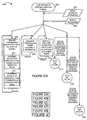
- FIG. 1is a drawing of an exemplary communication system implemented in accordance with the present invention.
- FIG. 2illustrates an exemplary base station, implemented in accordance with the invention.
- FIG. 3illustrates an exemplary wireless terminal, e.g., mobile node, implemented in accordance with the present invention.
- FIG. 4is a drawing of exemplary uplink dedicated control channel (DCCH) segments in an exemplary uplink timing and frequency structure in an exemplary orthogonal frequency division multiplexing (OFDM) multiple access wireless communications system.
- DCCHdownlink dedicated control channel
- OFDMorthogonal frequency division multiplexing
- FIG. 5includes a drawing of an exemplary dedicated control channel in an exemplary uplink timing and frequency structure in an exemplary orthogonal frequency division multiplexing (OFDM) multiple access wireless communications system at a time when each set of DCCH segments corresponding to a logical DCCH channel tone is in the full-tone format.
- OFDMorthogonal frequency division multiplexing
- FIG. 6includes a drawing of an exemplary dedicated control channel in an exemplary uplink timing and frequency structure in an exemplary orthogonal frequency division multiplexing (OFDM) multiple access wireless communications system at a time when each set of DCCH segments corresponding to a logical DCCH channel tone is in the split-tone format.
- OFDMorthogonal frequency division multiplexing
- FIG. 7includes a drawing of an exemplary dedicated control channel in an exemplary uplink timing and frequency structure in an exemplary orthogonal frequency division multiplexing (OFDM) multiple access wireless communications system at a time when some of the sets of DCCH segments corresponding to a logical DCCH channel tone are in the full-tone format and some of the sets of DCCH segments corresponding to a logical DCCH channel tone are in the split-tone format.
- OFDMorthogonal frequency division multiplexing
- FIG. 8is a drawing illustrating the use of format and mode in an exemplary uplink DCCH in accordance with the present invention, the mode defining the interpretation of the information bits in the DCCH segments.
- FIG. 9illustrates several examples corresponding to FIG. 8 illustrating different modes of operation.
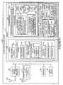
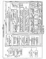
- FIG. 10is a drawing illustrating an exemplary default mode of the full tone format in a beaconslot for a given DCCH tone.
- FIG. 11illustrates an exemplary definition of the default mode in the full-tone format of the uplink DCCH segments in the first uplink superslot after the WT migrates to the ON state.
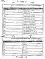
- FIG. 12is an exemplary summary list of dedicated control reports (DCRs) in the full-tone format for the default mode.
- DCRsdedicated control reports
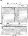
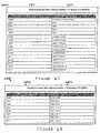
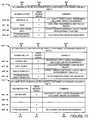
- FIG. 13is a table of an exemplary format for an exemplary 5 bit downlink SNR report (DLSNR 5 ) in non-DL macrodiversity mode.
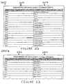
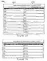
- FIG. 14is a table of an exemplary format of 5 bit downlink SNR report (DLSNR 5 ) in DL macrodiversity mode.
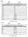
- FIG. 15is a table of an exemplary format of an exemplary 3 bit downlink delta SNR report (DLDSNR 3 ).
- FIG. 16is a table of an exemplary format for an exemplary 1 bit uplink request (ULRQST 1 ) report.
- FIG. 17is an exemplary table used to calculate exemplary control parameters y and z, the control parameters y and z being used in determining uplink multi-bit request reports conveying transmission request group queue information.
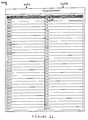
- FIG. 26is a table identifying bit format and interpretations associated with each of 32 bit patterns for an exemplary 5 bit uplink transmitter power backoff report (ULTxBKF 5 ), in accordance with the present invention.
- FIG. 27includes an exemplary power scaling factor table relating tone block power tier number to power scaling factor, implemented in accordance with the present invention.
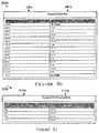
- FIG. 28is an exemplary uplink loading factor table used in communicating base station sector loading information, implemented in accordance with the present invention.
- FIG. 29is a table illustrating an exemplary format for a 4 bit downlink beacon ratio report (DLBNR 4 ), in accordance with the present invention.
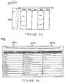
- FIG. 30is a drawing of an exemplary table describing the format of an exemplary 4 bit downlink self-noise saturation level of SNR report (DLSSNR 4 ), in accordance with the present invention.
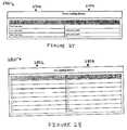
- FIG. 31is a drawing of a table illustrating an example of mapping between indicator report information bits and the type of report carried by the corresponding flexible report.
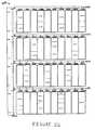
- FIG. 32is a drawing illustrating an exemplary default mode of the split tone format in a beaconslot for a given DCCH tone for an exemplary wireless terminal.
- FIG. 33illustrates an exemplary definition of the default mode in the split-tone format of the uplink DCCH segments in the first uplink superslot after the WT migrates to the ON state.
- FIG. 34provides an exemplary summary list of dedicated control reports (DCRs) in the split-tone format for the default mode.
- DCRsdedicated control reports
- FIG. 35is a table identifying bit format and interpretations associated with each of 16 bit patterns for an exemplary 4 bit uplink transmission backoff report (ULTxBKF 4 ), in accordance with the present invention.
- FIG. 36is an example of mapping between indicator report information bits and the type of report carried by the corresponding flexible report.
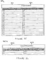
- FIG. 37is an exemplary specification of uplink dedicated control channel segment modulation coding in full-tone format.
- FIG. 38is a drawing of a table illustrating an exemplary specification of uplink dedicated control channel segment modulation coding in split-tone format.
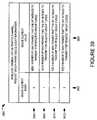
- FIG. 39is a drawing of a table illustrating exemplary wireless terminal uplink traffic channel frame request group queue count information.
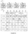
- FIG. 40includes drawings illustrating an exemplary set of four request group queues being maintained by a wireless terminal and drawings illustrating exemplary mappings of uplink data stream traffic flows to request queues for two exemplary wireless terminals, in accordance with an exemplary embodiment of the present invention.
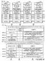
- FIG. 41illustrates an exemplary request group queue structure, multiple request dictionaries, a plurality of types of uplink traffic channel request reports, and grouping of sets of queues in accordance with exemplary formats used for each of the types of reports.
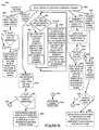
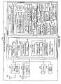
- FIG. 42comprising the combination of FIG. 42A , FIG. 42B , FIG. 42C , FIG. 42D , and FIG. 42E is a flowchart of an exemplary method of operating a wireless terminal in accordance with the present invention.
- FIG. 43is a flowchart of an exemplary method of operating a wireless terminal in accordance with the present invention.
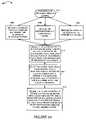
- FIG. 44is a flowchart of an exemplary method of operating a wireless terminal to report control information in accordance with the present invention.
- FIGS. 45 and 46are used to illustrate the use of an initial control information report set in an exemplary embodiment of the present invention.
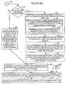
- FIG. 47is a flowchart of an exemplary method of operating a communications device in accordance with the present invention; the communications device including information indicating a predetermined report sequence for use in controlling the transmission of a plurality of different control information reports on a recurring basis.
- FIG. 48illustrates two exemplary different formats of initial control channel information report sets, the different format report sets including at least one segment conveying different sets of reports, in accordance with various embodiments of the present invention.
- FIG. 49illustrates a plurality of different initial control information report sets in accordance with various embodiments of the present invention, the different initial control information report sets having different numbers of segments.
- FIG. 50is a flowchart of an exemplary method of operating a wireless terminal in accordance with the present invention.
- FIG. 51is a drawing illustrating exemplary full-tone DCCH mode segments and exemplary split-tone DCCH mode segments allocated to exemplary wireless terminals, in accordance with various embodiments of the present invention.
- FIG. 52is a flowchart of a drawing of an exemplary method of operating a base station in accordance with the present invention.
- FIG. 53is a drawing illustrating exemplary full-tone DCCH mode segments and exemplary split-tone DCCH mode segments allocated to exemplary wireless terminals, in accordance with various embodiments of the present invention.
- FIG. 54is a drawing of a flowchart of an exemplary method of operating a wireless terminal in accordance with the present invention.
- FIG. 55is a drawing of an exemplary wireless terminal, e.g., mobile node, implemented in accordance with the present invention and using methods of the present invention.
- FIG. 56is a drawing of an exemplary base station, e.g., access node, implemented in accordance with the present invention and using methods of the present invention.
- FIG. 57is a drawing of an exemplary wireless terminal, e.g., mobile node, implemented in accordance with the present invention and using methods of the present invention.
- FIG. 58is a drawing of an exemplary base station, e.g., access node, implemented in accordance with the present invention and using methods of the present invention.
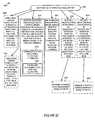
- FIG. 59comprising the combination of FIG. 59A , FIG. 59B and FIG. 59C is a flowchart of an exemplary method of operating a wireless terminal in accordance with the present invention.
- FIG. 60is a flowchart of an exemplary method of operating a wireless terminal to provide transmission power information to a base station in accordance with the present invention.
- FIG. 61is a table of an exemplary format for an exemplary 1 bit uplink request (ULRQST 1 ) report.
- FIG. 62is an exemplary table used to calculate exemplary control parameters y and z, the control parameters y and z being used in determining uplink multi-bit request reports conveying transmission request group queue information.
- FIG. 63 and FIG. 64define an exemplary request dictionary with the RD reference number equal to 0.
- FIG. 65 and FIG. 66includes tables which define an exemplary request dictionary with the RD reference number equal to 1.
- FIG. 67 and FIG. 68include tables which define an exemplary request dictionary with the RD reference number equal to 2.
- FIG. 69 and FIG. 70include tables which define an exemplary request dictionary with the RD reference number equal to 3.
- FIG. 71is a drawing of an exemplary wireless terminal, e.g., mobile node, implemented in accordance with the present invention and using methods of the present invention.
- FIG. 72is a drawing of an exemplary wireless terminal, e.g., mobile node, implemented in accordance with the present invention and using methods of the present invention.
- FIG. 73illustrates exemplary mapping for an exemplary wireless terminal of uplink data stream traffic flows to its request group queues at different times in accordance with various embodiments of the present invention.
- FIG. 74is a drawing of an exemplary wireless terminal, e.g., mobile node, implemented in accordance with the present invention and using methods of the present invention.
- FIG. 75is a drawing used to explain features of an exemplary embodiment of the present invention using a wireless terminal transmission power report.
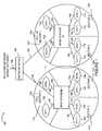
- FIG. 1shows an exemplary communication system 100 implemented in accordance with the present invention.
- Exemplary communications system 100includes multiple cells: cell 1 102 , cell M 104 .
- Exemplary system 100is, e.g., an exemplary orthogonal frequency division multiplexing (OFDM) spread spectrum wireless communications system such as a multiple access OFDM system.
- Each sectorsupports one or more carriers and/or downlink tones blocks. In some embodiments, each downlink tone block has a corresponding uplink tone block.
- Cell 102includes a first sector, sector 1 110 , a second sector, sector 2 112 , and a third sector, sector 3 114 .
- cell M 104includes a first sector, sector 1 122 , a second sector, sector 2 124 , and a third sector, sector 3 126 .
- Cell 1 102includes a base station (BS), base station 1 106 , and a plurality of wireless terminals (WTs) in each sector 110 , 112 , 114 .
- BSbase station
- WTswireless terminals
- Sector 1 110includes WT( 1 ) 136 and WT(N) 138 coupled to BS 106 via wireless links 140 , 142 , respectively;
- sector 2 112includes WT( 1 ′) 144 and WT(N′) 146 coupled to BS 106 via wireless links 148 , 150 , respectively;
- sector 3 114includes WT( 1 ′′) 152 and WT(N′′) 154 coupled to BS 106 via wireless links 156 , 158 , respectively.
- cell M 104includes base station M 108 , and a plurality of wireless terminals (WTs) in each sector 122 , 124 , 126 .
- WTswireless terminals
- Sector 1 122includes WT( 1 ′′′′) 168 and WT(N′′′′) 170 coupled to BS M 108 via wireless links 180 , 182 , respectively;
- sector 2 124includes WT( 1 ′′′′′) 172 and WT(N′′′′′) 174 coupled to BS M 108 via wireless links 184 , 186 , respectively;
- sector 3 126includes WT( 1 ′′′′′′) 176 and WT(N′′′′′′) 178 coupled to BS M 108 via wireless links 188 , 190 , respectively.
- System 100also includes a network node 160 which is coupled to BS 1 106 and BS M 108 via network links 162 , 164 , respectively.
- Network node 160is also coupled to other network nodes, e.g., other base stations, AAA server nodes, intermediate nodes, routers, etc. and the Internet via network link 166 .
- Network links 162 , 164 , 166may be, e.g., fiber optic cables.
- Each wireless, e.g. WT 1 136includes a transmitter as well as a receiver.
- At least some of the wireless terminalsare mobile nodes which may move through system 100 and may communicate via wireless links with the base station in the cell in which the WT is currently located, e.g., using a base station sector attachment point.
- the wireless terminals, (WTs), e.g. WT( 1 ) 136may communicate with peer nodes, e.g., other WTs in system 100 or outside system 100 via a base station, e.g. BS 106 , and/or network node 160 .
- WTs, e.g., WT( 1 ) 136may be mobile communications devices such as cell phones, personal data assistants with wireless modems, laptop computers with wireless modems, data terminals with wireless modems, etc.
- FIG. 2illustrates an exemplary base station 12 , implemented in accordance with the invention.
- Exemplary base station 12may be any of the exemplary base stations of FIG. 1 .
- the base station 12includes antennas 203 , 205 and receiver transmitter modules 202 , 204 .
- the receiver module 202includes a decoder 233 while the transmitter module 204 includes an encoder 235 .
- the modules 202 , 204are coupled by a bus 230 to an I/O interface 208 , processor (e.g., CPU) 206 and memory 210 .
- the I/O interface 208couples the base station 12 to other network nodes and/or the Internet.
- the memory 210includes routines, which when executed by the processor 206 , causes the base station 12 to operate in accordance with the invention.
- Memory 210includes communications routines 223 used for controlling the base station 12 to perform various communications operations and implement various communications protocols.
- the memory 210also includes a base station control routine 225 used to control the base station 12 to implement the steps of methods of the present invention.
- the base station control routine 225includes a scheduling module 226 used to control transmission scheduling and/or communication resource allocation. Thus, module 226 may serve as a scheduler.
- Base station control routine 225also includes dedicated control channel modules 227 which implement methods of the present invention, e.g., processing received DCCH reports, performing control related to DCCH mode, allocating DCCH segments, etc.
- Memory 210also includes information used by communications routines 223 , and control routine 225 .
- the data/information 212includes a set of data/information for a plurality of wireless terminal (WT 1 data/info 213 , WT N data/info 213 ′.
- WT 1 data/information 213includes mode information 231 , DCCH report information 233 , resource information 235 and sessions information 237 .
- Data/information 212also includes system data/information 229 .
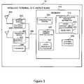
- FIG. 3illustrates an exemplary wireless terminal 14 , e.g., mobile node implemented in accordance with the present invention.
- Exemplary wireless terminal 14may be any of the exemplary wireless terminals of FIG. 1 .
- the wireless terminal 14e.g., mobile node may be used as a mobile terminal (MT).
- the wireless terminal 14includes receiver and transmitter antennas 303 , 305 which are coupled to receiver and transmitter modules 302 , 304 respectively.
- the receiver module 302includes a decoder 333 while the transmitter module 304 includes an encoder 335 .
- the receiver/transmitter modules 302 , 304are coupled by a bus 305 to a memory 310 .
- Processor 306under control of one or more routines stored in memory 310 causes the wireless terminal 14 to operate in accordance with the methods of the present invention.
- memory 310includes communications routine 323 and wireless terminal control routine 325 .
- Communications routine 323is used for controlling the wireless terminal 14 to perform various communications operations and implement various communications protocols.
- the wireless terminal control routine 325is responsible for insuring that the wireless terminal operates in accordance with the methods of the present invention and performs the steps in regard to wireless terminal operations.
- Wireless terminal control routine 325includes DCCH modules 327 , which implement methods of the present invention, e.g., control the performing of measurements used in DCCH reports, generate DCCH reports, control transmission of DCCH reports, control DCCH mode, etc.
- the memory 310also includes user/device/session/resource information 312 which may be accessed and used to implement the methods of the present invention and/or data structures used to implement the invention.
- Information 312includes DCCH report information 330 and mode information 332 .
- Memory 310also includes system data/information 329 , e.g., including uplink and downlink channel structure information.
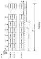
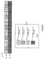
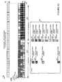
- FIG. 4is a drawing 400 of exemplary uplink dedicated control channel (DCCH) segments in an exemplary uplink timing and frequency structure in an exemplary orthogonal frequency division multiplexing (OFDM) multiple access wireless communications system.
- the uplink dedicated control channelis used to send Dedicated Control Reports (DCR) from wireless terminals to base stations.
- DCRDedicated Control Reports
- Vertical axis 402plots logical uplink tone index while horizontal axis 404 plots the uplink index of the halfslot within a beaconslot.
- an uplink tone blockincludes 113 logical uplink tones indexed ( 0 , . . .
- the first 9 OFDM symbol transmission time periods within a superslotare an access interval, and the dedicated control channel does not use the air link resources of the access interval.
- the exemplary dedicated control channelis subdivided into 31 logical tones (uplink tone index 81 406 , uplink tone index 82 408 , . . . , uplink tone index 111 410 ).
- Each logical uplink tone ( 81 , . . . , 111 ) in the logical uplink frequency structurecorresponds to a logical tone indexed with respect to the DCCH channel ( 0 , . . . , 30 ).
- each tone in the dedicated control channelthere are 40 segments in the beaconslot corresponding to forty columns ( 412 , 414 , 416 , 418 , 420 , 422 , . . . , 424 ).
- the segment structurerepeats on a beaconslot basis.
- For a given tone in the dedicated control channelthere are 40 segments corresponding to a beaconslot 428 ; each of the eight superslots of the beaconslot includes 5 successive segments for the given tone.
- first superslot 426 of beaconslot 428corresponding to tone 0 of the DCCH, there are five indexed segments (segment [ 0 ][ 0 ], segment [ 0 ][ 1 ], segment [ 0 ][ 2 ], segment [ 0 ][ 3 ], segment [ 0 ][ 4 ]).
- first superslot 426 of beaconslot 428corresponding to tone 1 of the DCCH, there are five indexed segments (segment [ 1 ][ 0 ], segment [ 1 ][ 1 ], segment [ 1 ][ 2 ], segment [ 1 ][ 3 ], segment [ 1 ][ 4 ]).
- first superslot 426 of beaconslot 428corresponding to tone 30 of the DCCH, there are five indexed segments (segment [ 30 ][ 0 ], segment [ 30 ][ 1 ], segment [ 30 ][ 2 ], segment [ 30 ][ 3 ], segment [ 30 ][ 4 ]).
- each segmente.g., segment [ 0 ][ 0 ]
- each segmentcomprises one tone for 3 successive half-slots, e.g., representing an allocated uplink air link resource of 21 OFDM tone-symbols.
- logical uplink tonesare hopped to physical tones in accordance with an uplink tone hopping sequence such that the physical tone associated with a logical tone may be different for successive half-slots, but remains constant during a given half-slot.
- a set of uplink dedicated control channel segments corresponding to a given tonecan use one of a plurality of different formats.
- the set of DCCH segmentscan use one of two formats: split tone format and full-tone format.
- the full tone formatthe set of uplink DCCH segments corresponding to a tone are used by a single wireless terminal.
- the split tone formatthe set of uplink DCCH segment corresponding to the tone are shared by up to three wireless terminals in a time division multiplexing manner.
- the base station and/or the wireless terminalcan, in some embodiments, change the format for a given DCCH tone, using predetermined protocols.
- the format of the uplink DCCH segments corresponding to a different DCCH tonecan, in some embodiments, be independently set and may be different.
- the wireless terminalin either format, shall support a default mode of the uplink dedicated control channel segments. In some embodiments, the wireless terminal supports the default mode of the uplink dedicated control channel segments and one or more additional modes of the uplink dedicated control channel segments. Such a mode defines the interpretation of the information bits in the uplink dedicated control channel segments.
- the base station and/or the WTcan, in some embodiments, change the mode, e.g., using an upper layer configuration protocol.
- the uplink DCCH segments corresponding to a different tone or those corresponding to the same tone but used by different WTscan be independently set and may be different.
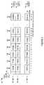
- FIG. 5includes a drawing 500 of an exemplary dedicated control channel in an exemplary uplink timing and frequency structure in an exemplary orthogonal frequency division multiplexing (OFDM) multiple access wireless communications system.
- Drawing 500may represent the DCCH 400 of FIG. 4 , at a time when each set of DCCH segments corresponding to a tone is in the full-tone format.
- Vertical axis 502plots logical tone index of the DCCH while horizontal axis 504 plots the uplink index of the halfslot within a beaconslot.
- the exemplary dedicated control channelis subdivided into 31 logical tones (tone index 0 506 , tone index 1 508 , . . . , tone index 30 510 ).
- Each logical tone of the dedicated control channelmay be assigned by the base station to a different wireless terminal using the base station as its current point of attachment. For example, logical (tone 0 506 , tone 1 508 , . . . , tone 30 510 ) may be currently assigned to (WT A 530 , WT B 532 , . . . , WT N′ 534 ), respectively.
- FIG. 6includes a drawing 600 of an exemplary dedicated control channel in an exemplary uplink timing and frequency structure in an exemplary orthogonal frequency division multiplexing (OFDM) multiple access wireless communications system.
- Drawing 600may represent the DCCH 400 of FIG. 4 , at a time when each set of DCCH segments corresponding to a tone is in the split-tone format.
- Vertical axis 602plots logical tone index of the DCCH while horizontal axis 604 plots the uplink index of the halfslot within a beaconslot.
- the exemplary dedicated control channelis subdivided into 31 logical tones (tone index 0 606 , tone index 1 608 , . . . , tone index 30 610 ).
- each tone in the dedicated control channelthere are 40 segments in the beaconslot corresponding to forty columns ( 612 , 614 , 616 , 618 , 620 , 622 , . . . , 624 ).
- Each logical tone of the dedicated control channelmay be assigned by the base station to up to 3 different wireless terminals using the base station as their current point of attachment.
- the segmentsalternate between the three wireless terminals, with 13 segments being allocated for each of the three wireless terminals, and the 40 th segment is reserved.
- This exemplary division of air link resources of the DCCH channelrepresents a total of 93 different wireless terminals being allocated DCCH channel resources for the exemplary beaconslot.
- logical tone 0 606may be currently assigned to and shared by WT A 630 , WT B 632 , and WT C 634 ; logical tone 1 608 may be currently assigned to and shared by WT D 636 , WT E 638 , and WT F 640 ; logical tone 30 610 may be currently assigned to WT M′′′ 642 , WT N′′′ 644 , and WT O′′′ 646 .
- each of the exemplary WTs( 630 , 632 , 634 , 636 , 638 , 640 , 642 , 644 , 646 ) is allocated 13 DCCH segments.
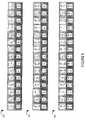
- FIG. 7includes a drawing 700 of an exemplary dedicated control channel in an exemplary uplink timing and frequency structure in an exemplary orthogonal frequency division multiplexing (OFDM) multiple access wireless communications system.
- Drawing 700may represent the DCCH 400 of FIG. 4 , at a time when some of the sets of DCCH segments corresponding to a tone are in the full-tone format and some of the sets of DCCH segments corresponding to a tone are in the split-tone format.
- Vertical axis 702plots logical tone index of the DCCH while horizontal axis 704 plots the uplink index of the halfslot within a beaconslot.
- the exemplary dedicated control channelis subdivided into 31 logical tones (tone index 0 706 , tone index 1 708 , tone index 2 709 , . . . , tone index 30 710 ).
- the set of segments corresponding to logical tone 0 708is in split-tone format and is currently assigned to and shared by WT A 730 , WT B 732 , and WTC 734 , each receiving 13 segments with one segment being reserved.
- the set of segments corresponding to logical tone 1 708is also in split-tone format, but is currently assigned to and shared by two WTs, WT D 736 , WT E 738 , each receiving 13 segments.
- tone 1 708there is a set of 13 unassigned segments, and one reserved segment.
- the set of segments corresponding to logical tone 2 709is also in split-tone format, but is currently assigned to one WT, WT F 739 , receiving 13 segments.
- For tone 2 709there are two sets with 13 unassigned segments per set, and one reserved segment.
- the set of segments corresponding to logical tone 30 710is in full-tone format and is currently assigned to WT P′ 740 , with WTP′ 740 receiving the full 40 segments to use.
- FIG. 8is a drawing 800 illustrating the use of format and mode in an exemplary uplink DCCH in accordance with the present invention, the mode defining the interpretation of the information bits in the DCCH segments.
- Row 802corresponding to one tone of the DCCH, illustrates 15 successive segments of the DCCH, in which the split tone-format is used and thus the tone is shared by three wireless terminals, and the mode used by any one of the three WTs can be different.
- row 804illustrates 15 successive DCCH segments using the full tone format and is used by a single wireless terminal.
- segments with vertical line shading 806are used by a 1 st WT user
- segments with diagonal line shading 808are used by a 2 nd WT user
- segments with horizontal line shading 810are used by a 3 rd WT user
- segments with crosshatch shading 812are used by a 4 th WT user.
- FIG. 9illustrates several examples corresponding to drawing 800 illustrating different modes of operation.
- 1 st , 2 nd and 3 rd WTsare sharing a DCCH tone in the split tone format while the 4 th WT is using a tone in the full tone format.
- Each of the WTs corresponding to the example of drawing 900are using the default mode of uplink dedicated control channel segments, following a default mode interpretation of the information bits in the DCCH segments.
- the default mode for split tone format (D s )is different than the default mode for full tone format (D F ).
- 1 st , 2 nd and 3 rd WTsare sharing a DCCH tone in the split tone format while the 4 th WT is using a tone in the full tone format.
- Each of the (1 st , 2 nd , and 3 rd ) WTs corresponding to the example of drawing 920are using different modes of uplink dedicated control channel segments, each following different interpretations of the information bits in the DCCH segments.
- the 1 st WTis using mode 2 for split-tone format
- the 2 nd wireless terminalis using the default mode for split-tone format
- the 3 rd WTis using mode 1 for split-tone format.
- the 4 th WTis using the default mode for full-tone format.
- 1 st , 2 nd and 3 rd WTsare sharing a DCCH tone in the split tone format while the 4 th WT is using a tone in the full tone format.
- Each of the (1 st , 2 nd , 3 rd , and 4 th ) WTs corresponding to the example of drawing 940are using different modes of uplink dedicated control channel segments, each following different interpretations of the information bits in the DCCH segments.
- the 1 st WTis using mode 2 for split-tone format
- the 2 nd wireless terminalis using the default mode for split-tone format
- the 3 rd WTis using mode 1 for split tone format
- the 4 th WTis using mode 3 for full-tone format.
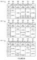
- FIG. 10is a drawing 1099 illustrating an exemplary default mode of the full tone format in a beaconslot for a given DCCH tone.
- each block( 1000 , 1001 , 1002 , 1003 , 1004 , 1005 , 1006 , 1007 , 1008 , 1009 , 1010 , 1011 , 1012 , 1013 , 1014 , 1015 , 1016 , 1017 , 1018 , 1019 , 1020 , 1021 , 1022 , 1023 , 1024 , 1025 , 1026 , 1027 , 1028 , 1029 , 1030 , 1031 , 1032 , 1033 , 1034 , 1035 , 1036 , 1037 , 1038 , 1039 ) represents one segment whose index s 2 ( 0 , .
- Each blocke.g., block 1000 representing segment 0 , conveys 6 information bits; each block comprises 6 rows corresponding to the 6 bits in the segment, where the bits are listed from the most significant bit to the least significant bit downwards from the top row to the bottom row as shown in rectangular region 1043 .
- the framing format shown in FIG. 10is used repeatedly in every beaconslot, when the default mode of full-tone format is used, with the following exception.
- the WTshall use the framing format shown in FIG. 11 .
- the first uplink superslotis defined: for a scenario when the WT migrates to the ON state from the ACCESS state, for a scenario when the WT migrates to the ON state from a HOLD state, and for a scenario when the WT migrates to the ON state from the ON state of another connection.
- FIG. 11illustrates an exemplary definition of the default mode in the full-tone format of the uplink DCCH segments in the first uplink superslot after the WT migrates to the ON state.
- Each blocke.g., block 1100 representing segment 0 of the superslot, conveys 6 information bits; each block comprises 6 rows corresponding to the 6 bits in the segment, where the bits are listed from the most significant bit to the least significant bit downwards from the top row to the bottom row as shown in rectangular region 1108 .
- the WTin the scenario of migrating from the HOLD to ON state, the WT starts to transmit the uplink DCCH channel from the beginning of the first UL superslot, and therefore the first uplink DCCH segment shall transport the information bits in the leftmost information column of FIG. 11 , the information bits of segment 1100 .
- the WTuses the framing format shown in FIG. 10 without the above exception of using the format shown in FIG. 11 .
- the uplink DCCH channel segmentsswitch to the framing format of FIG. 10 .
- the point of switching the framing formatmay or may not be the beginning of a beaconslot.
- Each uplink DCCH segmentis used to transmit a set of Dedicated Control Channel Reports (DCRs).
- DCRsDedicated Control Channel Reports
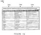
- An exemplary summary list of DCRs in the full-tone format for the default modeis given in table 1200 FIG. 12 .
- the information of table 1200is applicable to the partitioned segments of FIGS. 10 and 11 .
- Each segment of FIG. 10 and 11includes two or more reports as described in table 1200 .
- First column 1202 of table 1200describes abbreviated names used for each exemplary report. The name of each report ends with a number which specifies the number of bits of the DCR.
- Second column 1204 of table 1200briefly describes each named report.
- Third column 1206specifies the segment index s 2 of FIG. 10 , in which a DCR is to be transmitted, and corresponds to a mapping between table 1200 and FIG. 10 .
- the exemplary 5 bit absolute report of downlink signal to noise ratioshall now be described.
- the exemplary DLSNR 5uses one of the following two mode formats.
- the non-DL macrodiversity mode formatis used.
- the DL-macrodiversity mode formatis used if the WT is in the DL-macrodiversity mode; otherwise the non-macrodiversity mode format is used.
- whether the WT is in the DL-macrodiversity mode and/or how the WT switches between the DL macrodiversity mode and the non-DL macrodiversity modeare specified in an upper layer protocol.
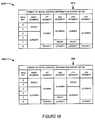
- FIG. 13is a table 1300 of an exemplary format of DLSNR 5 in non-DL macrodiversity mode.
- First column 1302list 32 possible bit pattern that may be represented by the 5 bits of the report.
- Second column 1304lists the value of wtDLPICHSNR being communicated to the base station via the report. In this example, incremental levels from ⁇ 12 dB to 29 dB can be indicated corresponding to 31 different bit patterns, while bit pattern 11111 is reserved.
- the DLSNR 5 reportis set to bit pattern 00000; if the calculated wtDLPICHSNR based on measurement is ⁇ 11.6 dB, the DLSNR 5 report is set to bit pattern 00000 because in table 1300 the entry with ⁇ 12 dB is the closet to the calculated value of ⁇ 11.6 dB; if the calculated wtDLPICHSNR based on measurement is ⁇ 11.4 dB, the DLSNR 5 report is set to bit pattern 00001 because in table 1300 the entry with ⁇ 11 dB is the closet to the calculated value of ⁇ 11.4 dB.
- FIG. 14is a table 1400 of an exemplary format of DLSNR 5 in DL macrodiversity mode.
- First column 1402list 32 possible bit patterns that may be represented by the 5 bits of the report.
- Second column 1404lists the value of wtDLPICHSNR being communicated to the base station via the report and an indication as to whether or not the connection is preferred.
- incremental levels of SNR from ⁇ 12 db to 13 dBcan be indicated corresponding to 32 different bit patterns. Sixteen of the bit patterns correspond to the case where the connection is not preferred; while the remaining sixteen bit patterns correspond to the case where the connection is preferred.
- the highest SNR value that can be indicated when a link is preferredis greater than the highest SNR value that can be indicated when a link is not preferred.
- the lowest SNR that can be indicated when a link is preferredis greater than the lowest SNR value that can be indicated when a link is not preferred.
- the wireless terminalindicates one and only one connection to be the preferred connection at any given time. Furthermore, in some such embodiments, if the WT indicates that a connection is preferred in a DLSNR 5 report, then the WT sends at least NumConsecutive Preferred consecutive DLSNR 5 reports indicating that the connection is preferred before the WT is allowed to a send a DLSNR 5 report indicating that another connection becomes the preferred one.
- the value of the parameter NumConsecutive preferreddepends on the format of the uplink DCCH channel, e.g., full-tone format vs split-tone format). In some embodiments the WT gets the parameter NumConsecutivePreferred in an upper level protocol. In some embodiments, the default value of NumConsecutivePreferred is 10 in the full-tone format.
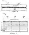
- FIG. 15is a table 1500 of an exemplary format of DLDSNR 3 .
- First column 1502lists 9 possible bit patterns that may represent the 3 information bits of the report.
- Second column 1504lists the reported difference in wtDLPICHSNR being communicated to the base station via the report ranging from ⁇ 5 dB to 5 dB.
- uplink traffic channel request reportswill now be described.
- three types of uplink traffic channel request reportsare used: an exemplary single bit uplink traffic channel request report (ULRQST 1 ), an exemplary three bit uplink traffic channel request report (ULRQST 3 ), and an exemplary four bit uplink traffic channel request report (ULRQST 4 ).
- the WTuses an ULRQST 1 , ULRQST 3 , or ULRQST 4 to report the status of the MAC frame queues at the WT transmitter.
- the MAC framesare constructed from the LLC frames, which are constructed from packets of upper layer protocols.
- any packetbelongs to one of four request groups (RG 0 , RG 1 , RG 2 , or RG 3 ).
- the mapping of packets to request groupsis done through higher layer protocols.
- the WTreports the number of MAC frames in the 4 request groups that the WT may intend to transmit. In the ARQ protocol, those MAC frames are marked as “new” or “to be retransmitted”.
- the WTshould report the information about N[ 0 : 3 ] to the base station sector so that the base station sector can utilize the information in an uplink scheduling algorithm to determine the assignment of uplink traffic channel segments.
- the WTuses the single bit uplink traffic channel request report (ULRQST 1 ) to report N[ 0 ]+N[ 1 ] according to table 1600 of FIG. 16 .
- Table 1600is an exemplary format for an ULRQST 1 report.
- First column 1602indicates the two possible bit patterns that may be conveyed while second column 1604 indicates the meaning of each bit pattern. If the bit pattern is 0, that indicates that there are no MAC frames that the WT intends to transmit in either request group 0 or request group 1 . If the bit pattern is 1, that indicates that the WT has at least one MAC frame in request group 0 or request group 1 that the WT intends to communicate.
- multiple request dictionariesare supported.
- a request dictionarydefines the interpretation of the information bits in uplink traffic channel request reports in the uplink dedicated control channel segments.
- the WTuses one request dictionary.
- the WTuses a default request dictionary.
- the WT and base station sectoruse an upper layer configuration protocol.
- the WTwhen the WT migrates from the ON state to the HOLD state, the WT keeps the last request dictionary used in the ON state so that when the WT migrates from the HOLD state to the ON state later, the WT continues to use the same request dictionary until the request dictionary is explicitly changed; however, if the WT leaves the ACTIVE state, then the memory of the last request dictionary is cleared.
- the ACTIVE stateincludes the ON state and the Hold state, but does not include the ACCESS state and sleep state.
- the wireless terminalfirst calculates one or more of the following two control parameters y and z, and uses one of the request dictionaries, e.g., Request dictionary (RD) reference number 0, RD reference number 1 , RD reference number 2 , RD reference number 3 .
- Table 1700 of FIG. 17is an exemplary table used to calculate control parameters y and z. First column 1702 lists a condition; second column 1704 lists the corresponding value of output control parameter y; third column 1706 lists the corresponding value of output control parameter z.
- x(in dBs) represents the value of the most recent 5 bit uplink transmit backoff report (ULTXBKF 5 ) and the value b (in dBs) of the most recent 4 bit downlink beacon ratio report (DLBNR 4 ).
- the WTchecks if the condition from first row 1710 is satisfied. If the test condition is satisfied, then the WT uses the corresponding y and z values of the row for calculating the ULRQST 3 or ULRQST 4 . However, if the condition is not satisfied the testing continues with the next row 1712 .
- Testingcontinues proceeding down the table 1700 in order from top to bottom ( 1710 , 1712 , 1714 , 1716 , 1718 , 1720 , 1722 , 1724 , 1726 , 1728 ) until the condition listed in column 1702 for a given row is satisfied.
- the WTuses an ULRQST 3 or ULRQST 4 to report the actual N[ 0 : 3 ] of the MAC frames queues according to a request dictionary.
- a request dictionaryis identified by a request dictionary (RD) reference number.
- At least some request dictionariesare such that any ULRQST 4 or ULRQST 3 may not completely include the actual N[ 0 : 3 ].
- a reportis in effect a quantized version of the actual N[ 0 : 3 ].
- the WTsends a report to minimize the discrepancy between the reported and actual MAC frame queues first for request group 0 and 1 , and then for request group 2 , and finally for request group 3 .
- the WThas the flexibility of determining a report to benefit the WT most. For example, assume that the WT is using exemplary request dictionary 1 (See FIGS.
- the WTmay use an ULRQST 4 to report N[ 1 ]+N[ 3 ] and use an ULRQST 3 to report N[ 2 ] and N[ 0 ].
- First column 1802identifies the bit pattern and bit ordering, most significant bit to least significant bit.
- Second column 1804identifies the interpretation associated with each bit pattern.
- An ULRQST 4 of table 1800conveys one of: (i) no change from the previous 4 bit uplink request, (ii) information about the N[ 0 ], and (iii) information about a composite of N[ 1 ]+N[ 2 ]+N[ 3 ] as a function of either control parameter y or control parameter z of table 1700 of FIG. 17 .
- First column 1902identifies the bit pattern and bit ordering, most significant bit to least significant bit.
- Second column 1904identifies the interpretation associated with each bit pattern.
- An ULRQST 3 of table 1900conveys: (i) information about the N[ 0 ] and (ii) information about a composite of N[ 1 ]+N[ 2 ]+N[ 3 ] as a function of control parameter y of table 1700 of FIG. 17 .
- First column 2002identifies the bit pattern and bit ordering, most significant bit to least significant bit.
- Second column 2004identifies the interpretation associated with each bit pattern.
- An ULRQST 4 of table 2000conveys one of: (i) no change from the previous 4 bit uplink request, (ii) information about the N[ 2 ], and (iii) information about a composite of N[ 1 ]+N[ 3 ] as a function of either control parameter y or control parameter z of table 1700 of FIG. 17 .
- First column 2102identifies the bit pattern and bit ordering, most significant bit to least significant bit.
- Second column 2104identifies the interpretation associated with each bit pattern.
- An ULRQST 3 of table 2100conveys: (i) information about N[ 0 ] and (ii) information about N[ 2 ].
- First column 2202identifies the bit pattern and bit ordering, most significant bit to least significant bit.
- Second column 2204identifies the interpretation associated with each bit pattern.
- An ULRQST 4 of table 2200conveys one of: (i) no change from the previous 4 bit uplink request, (ii) information about the N[ 1 ], and (iii) information about a composite of N[ 2 ]+N[ 3 ] as a function of either control parameter y or control parameter z of table 1700 of FIG. 17 .
- First column 2302identifies the bit pattern and bit ordering, most significant bit to least significant bit.
- Second column 2304identifies the interpretation associated with each bit pattern.
- An ULRQST 3 of table 2300conveys: (i) information about N[ 0 ] and (ii) information about N[ 1 ].
- First column 2402identifies the bit pattern and bit ordering, most significant bit to least significant bit.
- Second column 2404identifies the interpretation associated with each bit pattern.
- An ULRQST 4 of table 2400conveys one of: (i) no change from the previous 4 bit uplink request, (ii) information about N[ 1 ], (iii) information about N[ 2 ], and (iv) information about N[ 3 ] as a function of either control parameter y or control parameter z of table 1700 of FIG. 17 .
- First column 2502identifies the bit pattern and bit ordering, most significant bit to least significant bit.
- Second column 2504identifies the interpretation associated with each bit pattern.
- An ULRQST 3 of table 2500conveys: (i) information about N[ 0 ] and (ii) information about N[ 1 ].
- the methods of the present inventionfacilitate a wide range of reporting possibilities.
- control parameterse.g., based on SNR and backoff reports
- Table 1800 of FIG. 18For a four bit request where each bit pattern corresponds to a fixed interpretations and does not rely on control parameters, 16 possibilities exists.
- four of the bit patterns(0011, 0100, 0101, and 0110) can each have two different interpretations since control parameter y can have value 1 or 2.
- control parameter zcan have any of the values (1, 2, 3, 4, 5, 6, 7, 8, 9, 10). This use of control parameters expands the range of reporting for the 4 bit request report from 16 different possibilities to 111 possibilities.
- a wireless terminal backoff reportreports an amount of remaining power that the WT has to use for uplink transmissions for non-DCCH segments, e.g., including uplink traffic channel segment(s) after taking into account the power used to transmit the DCCH segments.
- wtULDCCHBackOffwtPowerMax ⁇ wtULDCCHTxPower; where wtULDCCHTxPower denotes the per-tone transmission power of the uplink DCCH channel in dBm, and wtPowerMax is the maximum transmission power value of the WT, also in dBm.
- the wtULDCCHTxPowerrepresents the instantaneous power and is calculated using the wtPowerNominal in the halfslot immediately preceeding the current uplink DCCH segment.
- the per tone power of the uplink DCCH channel relative to wtPowerNominalis 0 dBs.
- the value of wtPowerMaxdepends on the device capability of the WT, upon system specifications and/or upon regulations. In some embodiments, the determination of wtPowerMax is implementation dependent.
- FIG. 26is a table 2600 identifying bit format and interpretations associated with each of 32 bit patterns for an exemplary 5 bit uplink transmitter power backoff report (ULTxBKF 5 ), in accordance with the present invention.
- First column 2602identifies the bit pattern and bit ordering, most significant bit to least significant bit.
- Second column 2604identifies the reported WT uplink DCCH Backoff report values in dBs corresponding to each bit pattern. In this exemplary embodiment 30 distinct levels can be reported ranging from 6.5 dB to 40 dBs; two bit patterns are left as reserved.
- a wireless terminalcalculates wtULDCCHBackoff, e.g., as indicated above, selects the closet entry in table 2600 and uses that bit pattern for the report.
- the beacon ratio reportprovides information which is a function of received measured downlink broadcast signals, e.g., beacon signals and/or pilot signals, from a serving base station sector and from one or more other interfering base station sectors.
- the beacon ratio reportcan be used to estimate the relative proximity of the WT to other base station sectors.
- the beacon ratio reportcan be, and in some embodiments is, used at the serving BS sector in controlling the uplink rate of the WT to prevent excessive interference to other sectors.
- the beacon ratio reportin some embodiments, is based on two factors: (i) estimated channel gain ratios, denoted G i , and (ii) loading factors, denoted b i .
- the channel gain ratiosare defined, in some embodiments, as follows.
- the WTdetermines an estimate of the ratio of the uplink channel gain from the WT to any interfering Base station sector i (BSS i) to the channel gain from the WT to the serving BSS. This ratio is denoted as G i .
- the uplink channel gain ratiois not directly measurable at the WT.
- the ratiocan be estimated by comparing the relative received power of downlink signals from the serving and interfering BSSs.
- the reference downlink signalis the downlink beacon signal, which is well-suited for this purpose since it can be detected in very low SNR.
- beacon signalshave a higher per tone transmission power level than other downlink signals from a base station sector.
- the characteristics of the beacon signalare such that precise timing synchronization is not necessary to detect and measure the beacon signal.
- the beacon signalis, in some embodiments, a high power narrowband, e.g., single tone, two OFDM symbol transmission time period wide signal.
- a WTis able to detect and measure a beacon signal from a base station sector, where the detection and/or measurement of other downlink broadcast signals, e.g., pilot signals may not be feasible.
- the power measurement of the beacon signalmay not provide a very accurate representation of average channel gain, especially in a fading environment where the power changes rapidly.
- one beacon signalwhich occupies 2 successive OFDM symbol transmission time periods in duration and which corresponds to a downlink tone block of a base station sector, is transmitted for every beaconslot of 912 OFDM symbol transmission time periods.
- Pilot signalsare often transmitted much more frequently than beacon signals, e.g., in some embodiments pilot signals are transmitted during 896 out of the 912 OFDM symbol transmission time periods of a beaconslot. If the WT can detect the pilot signal from the BS sector, it can estimate the received beacon signal strength from the measured received pilot signal instead of using a beacon signal measurement.
- the scaling factors K, Z i and Z 0are either system constants, or can be inferred by the WT, from other information from the BS. In some embodiments, some of the scaling factors (K, Z i , Z 0 ) are system constants and some of the scaling factors (K, Z i , Z 0 ) are inferred by the WT, from other information form the BS.
- the scaling factors, Z i and Z 0are a function of the downlink tone block.
- an exemplary BSShas three power tier levels, and one of the three power tier levels is associated with each downlink tone block corresponding to a BSS attachment point. In some such embodiments, a different one of the three power tier levels is associated with each of the different tone blocks of the BSS.
- each power tier levelis associated with a nominal bss power level (e.g., one of bssPowerNominal 0 , bssPowerNominal 1 , and bssPowerNominal 2 ) and the pilot channel signal is transmitted at a relative power level with respect to a nominal bss power level for the tone block, e.g., 7.2 dB above the nominal bss power level being used by the tone block; however, the beacon per tone relative transmission power level for the BSS is the same irrespective of the tone block from which the beacon is transmitted, e.g., 23.8 dB above the bss power level used by the power tier 0 block (bssPowerNominal 0 ).
- a nominal bss power levele.g., one of bssPowerNominal 0 , bssPowerNominal 1 , and bssPowerNominal 2
- the pilot channel signalis transmitted at a relative power level with
- the beacon transmit powerwould be the same in each of the tone blocks, while the pilot transmit power is different, e.g. with the pilot transmit power of different tone blocks corresponding to different power tier levels.
- FIG. 27includes exemplary power scaling factor table 2700 , implemented in accordance with the present invention.
- First column 2702lists the use of the tone block as either a tier 0 tone block, tier 1 tone block, or tier 2 tone block.
- Second column 2704lists the scaling factor associated with each tier ( 0 , 1 , 2 ) tone block, as (1, bssPowerBackoff 01 , bssPowerBackoff 02 ), respectively.
- bssPowerBackoff 01is 6 dBs while bssPowerBackoff 02 is 12 dB.
- the DCCH DLBNR 4 reportcan be one of a generic beacon ratio report and a special beacon ratio report.
- a downlink traffic control channele.g., a DL.TCCH.FLASH channel
- a generic beacon ratio reportmeasures the relative interference cost the WT would generate to all the interfering beacons or the “closest” interfering beacon, if the WT were to transmit to the serving BSS in the current connection.
- a special beacon ratio reportmeasures the relative interference cost the WT would generate to a specific BSS, if the WT were to transmit to the serving BSS in the current connection.
- the specific BSSis the one indicated using information received in the Request for DLBNR 4 field of the special downlink frame.
- the specific BSSis the one whose bssSlope is equal to the value of the “Request for DLBNR 4 report field”, e.g., in unsigned integer format, and whose bssSectorType is equal to mod(ulUltraslotBeaconslotIndex, 3 ), where ulUltraslotBeaconslotIndex is the uplink index of the beaconslot within the ultraslot of the current connection.
- both the generic and the special beacon ratiosare determined from the calculated channel gain ratios G 1 , G 2 . . . , as follows.
- the WTreceives an uplink loading factor sent in a downlink broadcast system subchannel and determines a variable b 0 from uplink loading factor table 2800 of FIG. 28 .
- Table 2800includes a first column 2802 listing eight different values that may be used for the uplink loading factor ( 0 , 1 , 2 , 3 , 4 , 5 , 6 , 7 ); second column lists the corresponding values for the b value in dB (0, ⁇ 1, ⁇ 2, ⁇ 3, ⁇ 4, ⁇ 6, ⁇ 9, ⁇ infinity), respectively.
- the WTcalculates the following power ratio as the generic beacon ratio report: b 0 /(G 1 b 1 +G 2 b 2 + . . . ) when ulUltraslotBeaconslot Index is even or b 0 /max(G 1 b 1 +G 2 b 2 + . . . ) when ulUltraslotBeaconslotIndex is odd, where ulUltraslotBeaconslotIndex is the uplink index of the beaconslot within the ultraslot of the current connection and the operation+represents a regular addition.
- the WTWhen required to send a specific beacon ratio report, the WT, in some embodiments, calculates b 0 /(G k B k ), where index k represents the specific BSS k. In some embodiments, there are 18 indexed beaconslots within an ultraslot.
- FIG. 29is a table 2900 illustrating an exemplary format for a 4 bit downlink beacon ratio report (DLBNR 4 ), in accordance with the present invention.
- First column 2902lists the 16 various bit patterns that the report can convey, while second column 2904 lists the reported power ratio reported corresponding to each bit pattern, e.g., ranging from ⁇ 3 dB to 26 dBs.
- the wireless terminalreports the generic and specific beacon ratio reports by selecting and communicating the DLBNR 4 table entry that is closed to the determined report value.
- the generic and specific beacon ratio reportsuse the same table for DLBNR 4 , in some embodiments, different tables may be used.
- the WTderives the saturation level of the DL SNR, which is defined to be the DL SNR that the WT receiver would measure on a received signal if the BSS transmitted the signal at infinite power, if the base station were capable of transmitting such a signal and the wireless terminal was capable of measuring such a signal.
- the saturation levelcan be, and in some embodiments is, determined by the self-noise of the WT receiver, which may be caused by factor such as channel estimation errors.
- the followingis an exemplary method to derive the saturation level of the DL SNR.
- the saturation level of the DL SNRis equal to 1/a 0 .
- DL.NCHdownlink Null channel
- Table 3000 of FIG. 30is such an exemplary table describing the format of DLSSNR 4 .
- First column 3002indicates the 16 different possible bit patterns that can be conveyed by the DLSSNR 4 report, and second column 3004 lists saturation levels of DL SNR that are communicated corresponding to each bit pattern ranging from 8.75 dB to 29.75 dBs.
- a flexible reportis included in the DCCH, such that the WT decides which type of report to communicate and, the type of report can change from one flexible reporting opportunity to the next for a given WT using its allocated dedicated control channel segments.
- the WTuses a 2 bit type report (TYPE 2 ) to indicate the type of report selected by the WT to be communicated in a 4 bit body report (BODY 4 ) of the same DCCH segment including both the TYPE 2 and BODY 4 reports.
- Table 3100 of FIG. 31is an example of mapping between TYPE 2 report information bits and the type of report carried by the corresponding BODY 4 report.
- First column 3102indicates the four possible bit patterns for the 2 bit TYPE 2 report.
- Second column 3104indicates the type of report to be carried in the BODY 4 report of the same uplink dedicated control channel segment corresponding to the TYPE 2 report.
- Table 3100indicates that: bit pattern 00 indicates that BODY 4 report will be an ULRQST 4 report, Bit pattern 01 indicates the BODY 4 report will be a DLSSNR 4 report, and bit patterns 10 and 11 are reserved.
- a WTselects the TYPE 2 and BODY 4 reports by assessing the relative importance of the different types of reports from among which the selection may occur, e.g., the reports listed in table 3100 .
- the WTcan select the TYPE 2 independently from one segment to another.
- FIG. 32is a drawing 3299 illustrating an exemplary default mode of the split tone format in a beaconslot for a given DCCH tone for a first WT.
- each block( 3200 , 3201 , 3202 , 3203 3204 , 3205 , 3206 , 3207 , 3208 , 3209 , 3210 , 3211 , 3212 , 3213 , 3214 , 3215 , 3216 , 3217 , 3218 , 3219 , 3220 , 3221 , 3222 , 3223 , 3224 , 3225 , 3226 , 3227 , 3228 , 3229 , 3230 , 3231 , 3232 , 3323 , 3234 , 3235 , 3236 , 3237 , 3238 , 3239 ) represents one segment whose index s 2 ( 0 , .
- Each blocke.g., block 3200 representing segment 0 , conveys 8 information bits; each block comprises 8 rows corresponding to the 8 bits in the segment, where the bits are listed from the most significant bit to the least significant bit downwards from the top row to the bottom row as shown in rectangular region 3243 .
- the framing format shown in FIG. 32is used repeatedly in every beaconslot, when the default mode of split-tone format is used, with the following exception.
- the WTshall use the framing format shown in FIG. 33 .
- the first uplink superslotis defined: for a scenario when the WT migrates to the ON state from the ACCESS state, for a scenario when the WT migrates to the ON state from a HOLD state, and for a scenario when the WT migrates to the ON state from the ON state of another connection.
- FIG. 33illustrates an exemplary definition of the default mode in the split-tone format of the uplink DCCH segments in the first uplink superslot after the WT migrates to the ON state.
- Each blocke.g., block 3300 representing segment 0 of the superslot, conveys 8 information bits; each block comprises 8 rows corresponding to the 8 bits in the segment, where the bits are listed from the most significant bit to the least significant bit downwards from the top row to the bottom row as shown in rectangular region 3308 .
- the WTin the scenario of migrating from the HOLD to ON state, the WT starts to transmit the uplink DCCH channel from the beginning of the first UL superslot, and therefore the first uplink DCCH segment shall transport the information bits in the leftmost information column of FIG. 33 , the information bits of segment 3300 .
- the WTin the scenario of migrating from the ACCESS state to the ON state, the WT does not necessarily start from the beginning of the first UL superslot, but does still transmit the uplink DCCH segments according to the framing format specified in FIG. 33 .
- superlsot indexed halfslots ( 1 - 3 )correspond to one segment
- superslot indexed halfslots ( 10 - 12 )correspond to the next segment for the WT.
- the WTuses the framing format shown in FIG. 32 without the above exception of using the format shown in FIG. 33 .
- the uplink DCCH channel segmentsswitch to the framing format of FIG. 32 .
- the point of switching the framing formatmay or may not be the beginning of a beaconslot.
- there are five DCCH segments for a given DCCH tone for a superslot. For example, suppose that the first uplink superslot is of uplink beaconslot superslot index2, where beaconslot superslot index range is from 0 to 7 (superslot 0 , superlot 1 , . . . , superslot 7 ).
- Each uplink DCCH segmentis used to transmit a set of Dedicated Control Channel Reports (DCRs).
- DCRsDedicated Control Channel Reports
- An exemplary summary list of DCRs in the split-tone format for the default modeis given in table 3400 FIG. 34 .
- the information of table 3400is applicable to the partitioned segments of FIGS. 32 and 33 .
- Each segment of FIG. 32 and 33includes two or more reports as described in table 3400 .
- First column 3402 of table 3400describes abbreviated names used for each exemplary report. The name of each report ends with a number which specifies the number of bits of the DCR.
- Second column 3404 of table 3400briefly describes each named report.
- Third column 3406specifies the segment index s 2 of FIG. 32 , in which a DCR is to be transmitted, and corresponds to a mapping between table 3400 and FIG. 32 .
- FIGS. 32, 33 and 34describe the segments (indexed segments 0 , 3 , 6 , 9 , 12 , 15 , 18 , 21 , 24 , 27 , 30 , 33 , and 36 ) corresponding to a first WT in split tone format for default mode.
- a second wireless terminal that use the split tone format of default mode on the same logical tone in the DCCHwill follow the same report pattern but the segments will be shifted by one, thus the second WT uses indexed segments ( 1 , 4 , 7 , 10 , 13 , 16 , 19 , 22 , 25 , 28 , 31 , 34 , and 37 ).
- FIG. 32describes the segments (indexed segments 0 , 3 , 6 , 9 , 12 , 15 , 18 , 21 , 24 , 27 , 30 , 33 , and 36 ) corresponding to a first WT in split tone format for default mode.
- a second wireless terminal that use the split tone format of default mode on the same logical tone in the DCCHwill follow the same report pattern but the segments will be shifted by one, thus the second WT uses indexed segments 3301 and 3304 .
- a third wireless terminal that use the split tone format of default mode on the same logical tone in the DCCHwill follow the same report pattern but the segments will be shifted by two, thus the third WT uses indexed segments ( 2 , 5 , 8 , 11 , 14 , 17 , 20 , 23 , 26 , 29 , 33 , 35 , and 38 ).
- a third wireless terminal that use the split tone format of default mode on the same logical tone in the DCCHwill follow the same report pattern but the segments will be shifted by two, thus the third WT uses indexed segments 3305 .
- FIG. 33provides a representation corresponding to the replacement of the first superslot of a beaconslot corresponding to table 3299 , e.g., segment 3300 replaces segment 3200 and/or segment 3303 replaces segment 3203 .
- segment 3300replaces segment 3200
- segment 3303replaces segment 3203 .
- FIG. 32for each superslot, one or two segments are allocated to an exemplary wireless terminal using split-tone DCCH format, and the location of the allocated segments varies depending on the superslot of the beaconslot.
- segment 3300when used, is used to replace the first scheduled DCCH segment of a superslot and segment 3303 , when used, is used to replace the second scheduled DCCH segment of a superslot.
- segment 3300may replace segment 3206 and/or segment 3303 may replace segment 3309 .
- segment 3300may replace segment 3212 .
- the 5 bit absolute report of DL SNRfollows the same format in split-tone format default mode as used in the full-tone format default mode.
- the default value of NumConsecutivePreferredis different in the split-tone format than in the full-tone format, e.g., 6 in the split tone format default mode vs 10 in the full tone format default mode.
- the 3 bit DLDSNR 3 reportfollows the same format in the split-tone format default mode as used in the full-tone format default mode.
- the 4 bit DLSSNR 4 reportfollows the same format in the split-tone format default mode as used in the full-tone format default mode.
- the 4 bit uplink transmission backoff report (ULTxBKF 4 ) of the split tone format default modeis generated similarly to the ULTxBKF 5 of full tone format default mode, except table 3500 of FIG. 35 is used for the report.
- FIG. 35is a table 3500 identifying bit format and interpretations associated with each of 16 bit patterns for an exemplary 4 bit uplink transmission backoff report (ULTxBKF 4 ), in accordance with the present invention.
- First column 3502identifies the bit pattern and bit ordering, most significant bit to least significant bit.
- Second column 3504identifies the reported WT uplink DCCH Backoff report values in dBs corresponding to each bit pattern each bit pattern. In this exemplary embodiment 16 distinct levels can be reported ranging from 6 dB to 36 dBs.
- a wireless terminalcalculates wtULDCCHBackoff, e.g., as indicated above, selects the closest entry in table 3500 and uses that bit pattern for the report.
- the 4 bit DLBNR 4 reportfollows the same format in the split-tone format default mode as used in the full-tone format default mode.
- the 3 bit ULRQST 3 reportfollows the same format in the split-tone format default mode as used in the full-tone format default mode.
- the 4 bit ULRQST 4 reportfollows the same format in the split-tone format default mode as used in the full-tone format default mode.
- a flexible reportis included in the DCCH in the split-tone format in the default mode, such that the WT decides which type of report to communicate and, the type of report can change from one flexible reporting opportunity to the next for a given WT using its allocated dedicated control channel segments.
- the WTuses a 1 bit type report (TYPE 1 ) to indicate the type of report selected by the WT to be communicated in a 4 bit body report (BODY 4 ) of the same DCCH segment including both the TYPE 1 and BODY 4 reports.
- Table 3600 of FIG. 36is an example of mapping between TYPE 1 report information bits and the type of report carried by the corresponding BODY 4 report.
- First column 3602indicates the two possible bit patterns for the 1 bit TYPE 1 report.
- Second column 3604indicates the type of report to be carried in the BODY 4 report of the same uplink dedicated control channel segment corresponding to the TYPE 1 report.
- Table 3600indicates that: bit pattern 0 indicates that BODY 4 report will be an ULRQST 4 report, Bit pattern 01 indicates the BODY 4 report will be a Reserved report.
- a WTselects the TYPE 1 and BODY 4 reports by assessing the relative importance if the different types of reports from among which the selection may occur, e.g., the reports listed in table 3600 .
- the WTcan select the TYPE 1 independently from one segment to another.
- the encoding and modulation scheme used when the uplink dedicated control channel segment uses the full-tone formatis different than the encoding and modulation scheme used when the uplink dedicated control channel segment uses the split-tone format.
- b 5 , b 4 , b 3 , b 2 , b 1 , and b 0denote the information bits to be transmitted in the uplink dedicated control channel segment, where b 5 is the most significant bit and b 0 is the least significant bit.
- c 2 c 1 C 0(b 5 b 4 b 3 ). ⁇ (b 2 b 1 b 0 ), where. ⁇ is a bit-wise logical OR operation.
- the WTdetermines a group of seven modulation-symbols from information bit groups b 5 b 4 b 3 according to Table 3700 of FIG. 37 .
- Table 3700is an exemplary specification of uplink dedicated control channel segment modulation coding in full-tone format.
- First column 3702 of table 3700includes bit patterns for 3 ordered information bits;
- second column 3704includes corresponding sets of seven ordered coded modulation symbols, each set corresponding to a different possible bit pattern.
- the seven modulation-symbols determined from b 5 b 4 b 3are to be the seven most significant coded modulation-symbols of the output of the coding and modulation operation.
- the WTdetermines a group of seven modulation-symbols from information bit groups b 2 b 1 b 0 similarly using table 3700 , and uses the seven modulation-symbols obtained as the next most significant coded modulation-symbols of the output of the encoding and modulation operation.
- the WTdetermines a group of seven modulation-symbols from information bit groups c 2 c 1 c 0 similarly using table 3700 , and use the seven modulation-symbols obtained as the least significant coded modulation-symbols of the output of the coding and modulation operation.
- b 7 , b 6 , b 5 , b 4 , b 3 , b 2 , b 1 , and b 0denote the information bits to be transmitted in the uplink dedicated control channel segment, where b 7 is the most significant bit and b 0 is the least significant bit.
- c 3 c 2 c 1 c 0(b 7 b 6 b 5 b 4 ). ⁇ (b 3 b 2 b 1 b 0 ), where. ⁇ is a bit-wise logical OR operation.
- the WTdetermines a group of seven modulation-symbols from information bit groups b 7 b 6 b 5 b 4 according to Table 3800 of FIG. 38 .
- Table 3800is an exemplary specification of uplink dedicated control channel segment modulation coding in split-tone format.
- First column 3802 of table 3800includes bit patterns for 4 ordered information bits;
- second column 3804includes corresponding sets of seven ordered coded modulation symbols, each set corresponding to a different possible bit pattern.
- the seven modulation-symbols determined from b 7 b 6 b 5 b 4are to be the seven most significant coded modulation-symbols of the output of the coding and modulation operation.
- the WTdetermines a group of seven modulation-symbols from information bit groups b 3 b 2 b 1 b 0 similarly using table 3800 , and uses the seven modulation-symbols obtained as the next most significant coded modulation-symbols of the output of the encoding and modulation operation.
- the WTdetermines a group of seven modulation-symbols from information bit groups c 3 c 2 c 1 c 0 similarly using table 3800 , and uses the seven modulation-symbols obtained as the least significant coded modulation-symbols of the output of the coding and modulation operation.
- FIG. 39is a drawing of a table 3900 illustrating exemplary wireless terminal uplink traffic channel frame request group queue count information. Each wireless terminal maintains and updates its request group count information.
- there are four request groups(RG 0 , RG 1 , RG 2 , RG 3 ). Other embodiments may use different numbers of request groups. In some embodiments, different WTs in the system may have different numbers of request groups.
- First column 3902lists queue element index and second column 3904 lists queue element value.
- Drawing 4000 of FIG. 40includes an exemplary set of four request group queues ( 4002 , 4004 , 4006 , 4008 ) being maintained by a wireless terminal, in accordance with an exemplary embodiment of the present invention.
- Queue 0 4002is the queue for request group 0 information.
- Queue 0 information 4002includes a count of the total number of frames, e.g., MAC frames, of queue 0 traffic (N[ 0 ]) that the WT intends to transmit 4010 and the corresponding frames of uplink traffic (frame 1 4012 , frame 2 , 4014 , frame 3 4016 , . . . , frame N 0 4018 ).
- Queue 1 4004is the queue for request group 1 information.
- Queue 1 information 4004includes a count of the total number of frames, e.g., MAC frames, of queue 1 traffic (N[ 1 ]) that the WT intends to transmit 4020 and the corresponding frames of uplink traffic (frame 1 4022 , frame 2 , 4024 , frame 3 4026 , . . . , frame N 1 4028 ).
- Queue 2 4006is the queue for request group 2 information.
- Queue 2 information 4006includes a count of the total number of frames, e.g., MAC frames, of queue 2 traffic (N[ 2 ]) that the WT intends to transmit 4030 and the corresponding frames of uplink traffic (frame 1 4032 , frame 2 , 4034 , frame 3 4036 , . .
- Queue 3 4008is the queue for request group 3 information.
- Queue 3 information 4008includes a count of the total number of frames, e.g., MAC frames, of queue 3 traffic (N[ 3 ]) that the WT intends to transmit 4040 and the corresponding frames of uplink traffic (frame 1 4042 , frame 2 , 4044 , frame 3 4046 , . . . , frame N 3 4048 ).
- the request queuesfor at least some wireless terminals, are priority queues.
- request group 0 queue 4002is used for the highest priority traffic
- request group 1 queue 4004is used for the 2 nd highest priority traffic
- request group 2 queue 4006is used for the third highest priority traffic
- request group 3 queue 4008is used for the lowest priority traffic, from the perspective of the individual wireless terminal.
- the traffic in at least some request queues during at least some times for at least some wireless terminalshave different priorities.
- priorityis one factor considered when mapping a traffic flow to a request queue.
- priorityis one factor considered when scheduling/transmitting traffic.
- priorityis representative of relative importance. In some embodiments, all other factors being equal, traffic belonging to a higher priority is scheduled/transmitted more often than traffic belonging to lower priorities.
- Drawing 4052 of FIG. 40illustrates exemplary mapping for a first WT, WT A, of uplink data stream traffic flows to its request group queues.
- First column 4054includes information type of the data stream traffic flow;
- second column 4056includes the identified queue (request group);
- third column 4058includes comments.
- First row 4060indicates that control information is mapped to request group 0 queue. Flows mapped to the request group 0 queue are considered high priority, have strict latency requirements, require low latency and/or have low bandwidth requirements.
- Second row 4062indicates that voice information is mapped to request group 1 queue. Flows mapped to the request group 1 queue also require low latency but have a lower priority level than request group 0 .
- Third row 4064indicates that gaming and audio stream application A is mapped to request group 2 queue.
- Fourth row 4066indicates that FTP, web browsing, and video stream application A are mapped to request group 3 queue. Flows mapped to the request group 3 , are delay insensitive and/or require high bandwidth.
- Drawing 4072 of FIG. 40illustrates exemplary mapping for a second WT, WTB, of uplink data stream traffic flows to its request group queues.
- First column 4074includes information type of the data stream traffic flow;
- second column 4076includes the identified queue (request group);
- third column 4078includes comments.
- First row 4080indicates that control information is mapped to request group 0 queue. Flows mapped to the request group 0 queue are considered high priority, have strict latency requirements, require low latency and/or have low bandwidth requirements.
- Second row 4082indicates that voice and audio stream application A information are mapped to request group 1 queue. Flows mapped to the request group 1 queue also require low latency but have a lower priority level than request group 0 .
- Third row 4084indicates that gaming and audio stream application B, and image stream application A are mapped to request group 2 queue. For flows mapped to the request group 2 , latency is somewhat important and the bandwidth requirements are slightly higher than for voice. Fourth row 4086 indicates that FTP, web browsing, and image stream application B are mapped to request group 3 queue. Flows mapped to the request group 3 , are delay insensitive and/or require high bandwidth.
- WT A and WT Buse different mapping from their uplink data stream traffic flows to their set of request group queues.
- audio stream application Ais mapped to request group queue 2 for WTA, while the same audio stream application A is mapped to request group queue 1 for WTB.
- different WTsmay have different types of uplink data stream traffic flows.
- WT Bincludes an audio stream application B that is not included for WT A.
- This approachallows each WT to customize and/or optimize its request queue mapping to match the different types of data being communicated via its uplink traffic channel segments.
- a mobile nodesuch as a voice and text message cell phone has different types of data streams than a mobile data terminal used primarily for on-line gaming and web browsing, and would typically have a different mapping of data streams to request group queues.
- the mapping from uplink data stream traffic flows to request group queues for a WTmay change with time.
- Drawing 4001 of FIG. 40Aillustrates exemplary mapping for a WT C at a first time T 1 , of uplink data stream traffic flows to its request group queues.
- First column 4003includes information type of the data stream traffic flow;
- second column 4005includes the identified queue (request group);
- third column 4007includes comments.
- First row 4009indicates that control information is mapped to request group 0 queue. Flows mapped to the request group 0 queue are considered high priority, have strict latency requirements, require low latency and/or have low bandwidth requirements.
- Second row 4011indicates that voice information is mapped to request group 1 queue.
- Flows mapped to the request group 1 queuealso require low latency but have a lower priority level than request group 0 .
- Third row 4013indicates that gaming and audio stream application A is mapped to request group 2 queue. For flows mapped to the request group 2 , latency is somewhat important and the bandwidth requirements are slightly higher than for voice.
- Fourth row 4015indicates that FTP, web browsing, and video stream application A are mapped to request group 3 queue. Flows mapped to the request group 3 , are delay insensitive and/or require high bandwidth.
- Drawing 4017 of FIG. 40Aillustrates exemplary mapping for a WT C at a second time T 2 , of uplink data stream traffic flows to its request group queues.
- First column 4019includes information type of the data stream traffic flow;
- second column 4021includes the identified queue (request group);
- third column 4023includes comments.
- First row 4025indicates that control information is mapped to request group 0 queue. Flows mapped to the request group 0 queue are considered high priority, have strict latency requirements, require low latency and/or have low bandwidth requirements.
- Second row 4027indicates that voice application and a gaming application is mapped to request group 1 queue. Flows mapped to the request group 1 queue also require low latency but have a lower priority level than request group 0 .
- Third row 4029indicates that video streaming application A is mapped to request group 2 queue. For flows mapped to the request group 2 , latency is somewhat important and the bandwidth requirements are slightly higher than for voice.
- Fourth row 4031indicates that FTP, web browsing and video streaming application B are mapped to request group 3 queue. Flows mapped to the request group 3 , are delay insensitive and/or require high bandwidth.
- Drawing 4033 of FIG. 73illustrates exemplary mapping for a WT C at a third time T 3 , of uplink data stream traffic flows to its request group queues.
- First column 4035includes information type of the data stream traffic flow;
- second column 4037includes the identified queue (request group);
- third column 4039includes comments.
- First row 4041indicates that control information is mapped to request group 0 queue. Flows mapped to the request group 0 queue are considered high priority, have strict latency requirements, require low latency and/or have low bandwidth requirements.
- Second row 4043 and third row 4045indicate that no data traffic applications are mapped to request group 1 and request group 2 queues, respectively.
- Fourth row 4047indicates that FTP and web browsing are mapped to request group 3 queue. Flows mapped to the request group 3 , are delay insensitive and/or require high bandwidth.
- WT Cuses different mappings from their uplink data stream traffic flows to their set of request group queues at the three times T 1 , T 2 and T 3 .
- audio stream application Ais mapped to request group queue 2 at time T 1
- the same audio stream application Ais mapped to request group queue 1 at time T 2 .
- the WTmay have different types of uplink data stream traffic flows at different times.
- the WTincludes a video stream application B that is not included at time T 1 .
- the WTmay have no uplink data stream traffic flows mapped to a specific request group queue at a given time.
- FIG. 41illustrates an exemplary request group queue structure, multiple request dictionaries, a plurality of types of uplink traffic channel request reports, and grouping of sets of queues in accordance with exemplary formats used for each of the types of reports.
- the exemplary structureaccommodates four request dictionaries.
- the exemplary structureuses three types of uplink traffic channel request reports (a 1 bit report, a 3-bit report, and a 4-bit report).
- FIG. 41includes: exemplary queue 0 (request group 0 ) information 4102 which includes the total number of frames, e.g., MAC frames, of queue 0 traffic that an exemplary WT intends to transmit (N[ 0 ]) 4110 , exemplary queue 1 (request group 1 ) information 4104 which includes the total number of frames, e.g., MAC frames, of queue 1 traffic that an exemplary WT intends to transmit (N[ 1 ]) 4112 , exemplary queue 2 (request group 2 ) information 4106 which includes the total number of frames, e.g., MAC frames, of queue 2 traffic that an exemplary WT intends to transmit (N[ 2 ]) 4114 , and exemplary queue 3 (request group 3 ) information 4108 which includes the total number of frames, e.g., MAC frames, of queue 3 traffic that an exemplary WT intends to transmit (N[ 3 ]) 4116 .
- the set of queue 0 info 4102 , queue 1 info 4104 , queue 2 info 4106 and queue 3 info 4108correspond to one WT in the system.
- Each WT in the systemmaintains its set of queues, tracking uplink traffic frames that it may intend to transmit.
- Table 4118identifies grouping of queue sets used by different types of request reports as a function of the dictionary in use.
- Column 4120identifies the dictionary.
- the first type of exemplary reportis, e.g., a 1 bit information report.
- Column 4122identifies the first set of queues used for first type reports.
- the first set of queuesis the set ⁇ queue 0 and queue 1 ⁇ for the first type of report irrespective of the request dictionary.
- Column 4124identifies the second set of queues used for second type reports.
- the second set of queuesis the set ⁇ queue 0 ⁇ for the second type of report irrespective of the request dictionary.
- Column 4126identifies the third set of queues used for second type reports.
- the third set of queuesis: (i) the set ⁇ queue 1 , queue 2 , queue 3 ⁇ for the second type of report for request dictionary 0 , (ii) the set of ⁇ queue 2 ⁇ for the second type of report for request dictionary 1 , and (iii) the set of ⁇ queue 1 ⁇ for the second type of report for dictionary 2 and 3 .
- the third type of reportuses a fourth and fifth set of queues for each dictionary.
- the third type of reportuses a sixth set of queues for dictionaries 1 , 2 , and 3 .
- the third type of reportuses a seventh set of queues for dictionary 3 .
- Column 4128identifies that the fourth set of queues for the third type of report is the set ⁇ queue 0 ⁇ irrespective of the dictionary.
- Column 4130identifies that the fifth set of queues for the third type of report is the set ⁇ queue 1 , queue 2 , queue 3 ⁇ for dictionary 0 , the set ⁇ queue 2 ⁇ for dictionary 1 , the set ⁇ queue 1 ⁇ for dictionaries 2 and 3 .
- Column 4132identifies that the sixth set of queues for the third type of report is the set ⁇ queue 1 , queue 3 ⁇ for dictionary 1 , the set ⁇ queue 2 , queue 3 ⁇ for dictionary 2 , and the set ⁇ queue 2 ⁇ for dictionary 3 .
- Column 4134identifies that the seventh set of queues for the third type of report is the set ⁇ queue 3 ⁇ for dictionary 3 .
- the (first, second, and third) types of reportsmay be the exemplary (ULRQST 1 , ULRQST 3 , and ULRQST 4 ) reports, respectively, of FIGS. 16-25 .
- the sets of queues used(See table 4118 ) will be described with respect to the dictionary 0 for the exemplary ULRQST 1 , ULRQST 3 , and ULRQST 4 .
- Queue stats of second set of queues ⁇ queue 0 ⁇ and third set of queues ⁇ queue 1 , queue 2 , queue 3 ⁇are jointly coded in an ULRQST 3 .
- Queue stats of fourth set of queues ⁇ queue 0 ⁇ or the fifth set of queues ⁇ queue 1 , queue 2 , queue 3 ⁇are coded in an ULRQST 4 .
- the first type of reportis independent of request dictionary and uses the first set of queues of table 4118
- a second type of reportcommunicates queue stat information about both a second set of queues and a corresponding third set of queues from table 4118
- a third type of reportcommunicates queue stat information about one of: a fourth sets of queues, a corresponding fifth set of queues, a corresponding sixth set of queues, and a corresponding seventh set of queues.
- FIG. 42is a flowchart 4200 of an exemplary method of operating a wireless terminal in accordance with the present invention.
- Operation of the exemplary methodstarts in step 4202 , where the WT is powered on and initialized.
- Queue definition information 4204e.g., mapping information defining mapping of traffic flows from various applications into MAC frames of specific request group queues and various grouping of request groups into sets of request groups, and sets of request dictionary information 4206 are available for use by the wireless terminal.
- the information 4204 and 4206may be pre-stored in the wireless terminal in non-volatile memory.
- a default request dictionary from among the plurality of available request dictionariesis used by the wireless terminal initially, e.g., request dictionary 0 . Operation proceeds from start step 4202 to steps 4208 , 4210 and 4212 .
- step 4208the wireless terminal maintains transmission queue stats for a plurality of queues, e.g., request group 0 queue, request group 1 queue, request group 2 queue and request group 3 queue.
- Step 4208includes sub-step 4214 and sub-step 4216 .
- the wireless terminalincrements queue stats when data to be transmitted is added to a queue. For example, new packets from an uplink data stream flow, e.g., a voice communications session flow, are mapped as MAC frames to one of the request groups, e.g., request group 1 queue and a queue stat, e.g., N[ 1 ] representing the total number of request group 1 frames that the WT intends to transmit is updated.
- different wireless terminalsuse different mappings.
- the WTdecrements the queue stats when data to be transmitted is removed from a queue. For example, the data to be transmitted may be removed from the queue because the data has been transmitted, the data has been transmitted and a positive acknowledgement was received, the data no longer needs to be transmitted because a data validity timer has expired, or the data no longer needs to be transmitted because the communications session has been terminated.
- the wireless terminalIn step 4210 , the wireless terminal generates transmission power availability information. For example, the wireless terminal calculates the wireless terminal transmission backoff power, determines a wireless terminal transmission backoff power report value, and stores backoff power information. Step 4210 is performed on an ongoing basis with the stored information being updated, e.g., in accordance with a DCCH structure.
- the wireless terminalIn step 4212 , the wireless terminal generates transmission path loss information for at least two physical attachment points. For example, the wireless terminal measures received pilot and/or beacon signals from at least two physical attachment points calculates a ratio value, determines a beacon ratio report value, e.g., corresponding to a generic beacon ratio report of a first or second type or a specific beacon ratio report, and stores the beacon ratio report information. Step 4212 is performed on an ongoing basis with the stored information being updated, e.g. in accordance with a DCCH structure.
- each reporting opportunity in a (first, second, third) set of predetermined transmission queue stats reporting opportunities operationgoes to (sub-routine 1 4224 , sub-routine 2 4238 , subroutine 3 4256 ), via (step 4218 , step 4220 , step 4222 ), respectively.
- each first set of predetermined transmission queue stat reporting opportunitiescorresponds to each one-bit uplink traffic channel request reporting opportunity in the timing structure. For example, if a WT is communicating over DCCH segments using the full-tone DCCH format default mode, e.g., of FIG. 10 , the WT receives 16 opportunities to send ULRQST 1 in a beaconslot.
- each second set of predetermined transmission queue stat reporting opportunitiescorresponds to each three-bit uplink traffic channel request reporting opportunity in the timing structure. For example, if a WT is communicating over DCCH segments using the full-tone DCCH format default mode, e.g., of FIG. 10 , the WT receives 12 opportunities to send ULRQST 3 in a beaconslot. If a WT is communicating over DCCH segments using the split-tone DCCH format default mode, e.g., of FIG. 32 , the WT receives 6 opportunities to send ULRQST 3 in a beaconslot.
- each third set of predetermined transmission queue stat reporting opportunitiescorresponds to each four-bit uplink traffic channel request reporting opportunity in the timing structure.
- a WTFor example, if a WT is communicating over DCCH segments using the full-tone DCCH format default mode, e.g., of FIG. 10 , the WT receives 9 opportunities to send ULRQST 4 in a beaconslot. If a WT is communicating over DCCH segments using the split-tone DCCH format default mode, e.g., of FIG. 32 , the WT receives 6 opportunities to send ULRQST 4 in a beaconslot. For each flexible report in which the WT decides to send an ULRQST 4 , operation also goes to sub-routine 4256 via connecting node 4222 .
- Operationstarts in step 4226 , and the WT receives backlog information for a first set of queues, e.g. the set of ⁇ Queue 0 , Queue 1 ⁇ where the information received is N[ 0 ]+N[ 1 ]. Operation proceeds from step 4226 to step 4230 .
- a first number of information bitse.g., 1 information bit
- step 4230the WT transmits a first number of information bits, e.g., 1 information bit, indicating a traffic backlog in the first set of queues, e.g. the information bit is set equal to 1. Operation proceeds from either step 4232 or step 4234 to return step 4236 .
- step 4240the WT receives backlog information for a second set of queues, e.g. the set of ⁇ Queue 0 ⁇ where the information received is N[ 0 ].
- the WTalso receives backlog information for a third set of queues, e.g., the set ⁇ queue 1 , queue 2 , queue 3 ⁇ or ⁇ queue 2 ⁇ or ⁇ queue 1 ⁇ depending on the request dictionary in use by the WT.
- the WTmay receive (N[ 1 ]+N[ 2 ]+N[ 3 ], N[ 2 ], N[ 1 ], N[ 1 ]), respectively. Operation proceeds from step 4240 to step 4246 .
- step 4246the WT jointly encodes the backlog information corresponding to the second and third sets of queues into a second predetermined number of information bits, e.g., 3, said joint encoding optionally including quantization.
- sub-step 4248 and sub-step 4250are performed as part of step 4246 .
- sub-step 4248 and sub-step 4250are performed as part of step 4246 .
- Sub-step 4248directs operation to a quantization level control factor subroutine.
- Sub-step 4250calculates a quantization level as a function of a determined control factor.
- each of the quantization levelsare calculated as a function of control factor y.
- sub-steps 4248 and 4250are performed in determining the information bit pattern to place in the ULRQST 3 report.
- request dictionary 1as shown in FIG. 21 .
- none of the quantization levelsare calculated as a function of a control factor, e.g. y or z, and therefore sub-step 4248 and 4250 are not performed.
- Operationproceeds from step 4246 to step 4252 , where the WT transmits the jointly coded backlog information for the second and third sets of queues using the second predetermined number of information bits, e.g., 3 information bits. Operation proceeds from step 4252 to return step 4254 .
- Operationstarts in step 4258 , and the WT receives backlog information for a fourth set of queues, e.g. the set of ⁇ Queue 0 ⁇ where the information received is N[ 0 ].
- the WTalso receives backlog information for a fifth set of queues, e.g., the set ⁇ queue 1 , queue 2 , queue 3 ⁇ or ⁇ queue 2 ⁇ or ⁇ queue 1 ⁇ depending on the request dictionary in use by the WT.
- the WTmay receive (N[ 1 ]+N[ 2 ]+N[ 3 ], N[ 2 ], N[ 1 ], N[ 1 ]), respectively.
- the WTmay also receives backlog information for a sixth set of queues, e.g., the set ⁇ queue 1 , queue 3 ⁇ or ⁇ queue 2 , queue 3 ⁇ or ⁇ queue 2 ⁇ depending on the request dictionary in use by the WT.
- the WTmay receive (N[ 1 ]+N[ 3 ], N[ 2 ]+N[ 3 ], N[ 2 ]), respectively.
- the WTmay also receive backlog information for a seventh set of queues, e.g., the set ⁇ queue 3 ⁇ if request dictionary 3 is in use by the WT. Operation proceeds from step 4258 to step 4266 .
- step 4268the WT encodes the backlog information corresponding to one of the fourth, fifth, sixth, and seventh sets of queues into a third predetermined number of information bits, e.g., 4, said encoding optionally including quantization.
- sub-step 4270 and sub-step 4272are performed as part of step 4268 .
- sub-step 4270 and sub-step 4272are performed as part of step 4268 .
- Sub-step 4270directs operation to a quantization level control factor subroutine.
- Sub-step 4272calculates a quantization level as a function of a determined control factor.
- Operationproceeds from step 4268 to step 4274 , where the WT transmits the coded backlog information for one of the fourth, fifth, sixth, and seventh sets of queues using the third predetermined number of information bits, e.g., 4 information bits. Operation proceeds from step 4274 to return step 4276 .
- Exemplary quantization level control factor subroutine 4278will now be described.
- the exemplary quantization level control factor subroutine 4278 implementationincludes the use of table 1700 of FIG. 17 .
- First column 1702lists a condition;
- second column 1704lists the corresponding value of output control parameter y;
- third column 1706lists the corresponding value of output control parameter Z.
- Operationstarts in step 4279 , and the subroutine receives power information 4280 , e.g., the last DCCH transmitter power backoff report, and path loss information 4282 , e.g., the last reported beacon ratio report. Operation proceeds from step 4279 to step 4284 , where the WT checks as to whether or not the power information and path loss information satisfy a first criteria.
- step 4288the WT checks as to whether or not the power information and path loss information satisfy a second criteria.
- step 4292the wireless terminal tests as to whether or not the power information and path loss information satisfy an Nth criteria.
- step 4286the WT returns at least one control factor value, e.g., Y and/or Z.
- FIG. 43is a flowchart 4300 of an exemplary method of operating a wireless terminal in accordance with the present invention. Operation starts in step 4302 , where the wireless terminal is powered on, initialized, has established a connection with a base station. Operation proceeds from start step 4302 to step 4304 .
- step 4304the wireless terminal determines whether the WT is operating in a full-tone format DCCH mode or a split-tone format DCCH mode. For each DCCH segment allocated to the WT in full-tone format DCCH mode, the WT proceeds from step 4304 to step 4306 . For each DCCH segment allocated to the WT in split-tone format DCCH mode, the WT proceeds from step 4304 to step 4308 .
- step 4306the WT determines a set of 21 coded modulation-symbol values from 6 information bits (b 5 , b 4 , b 3 , b 2 , b 1 , b 0 ).
- Step 4306includes sub-steps 4312 , 4314 , 4316 , and 4318 .
- Operationproceeds from step 4312 to step 4314 .
- the WTdetermines the seven most-significant modulation symbols using a first mapping function and 3 bits (b 5 , b 4 , b 3 ) as input.
- Operationproceeds from sub-step 4314 to sub-step 4316 .
- the WTdetermines the seven next most significant modulation symbols using the first mapping function and 3 bits (b 2 , b 1 , b 0 ) as input.
- Operationproceeds from sub-step 4316 to sub-step 4318 .
- the WTdetermines the seven least-significant modulation symbol using the first mapping function and 3 bits (c 2 , c 1 , c 0 ) as input.
- step 4308the WT determines a set of 21 coded modulation-symbol values from 8 information bits (b 7 , b 6 , b 5 , b 4 , b 3 , b 2 , b 1 , b 0 ).
- Step 4308includes sub-steps 4320 , 4322 , 4324 , and 4326 .
- the WTdetermines 4 additional bits (c 3 , c 2 , c 1 , c 0 ) as a function of the 8 information bits.
- c 3 c 2 c 1 c 0(b 7 b 6 b 5 b 4 ). ⁇ (b 3 b 2 b 1 b 0 ) where. ⁇ is a bit wise exclusive OR operation. Operation proceeds from step 4320 to step 4322 . In sub-step 4322 , the WT determines the seven most-significant modulation symbols using a second mapping function and 4 bits (b 7 , b 6 , b 5 , b 4 ) as input. Operation proceeds from sub-step 4322 to sub-step 4324 .
- sub-step 4324the WT determines the seven next most significant modulation symbols using the second mapping function and 4 bits (b 3 , b 2 , b 1 , b 0 ) as input. Operation proceeds from sub-step 4324 to sub-step 4326 . In sub-step 4326 , the WT determines the seven least-significant modulation symbol using the second mapping function and 4 bits (c 3 , c 2 , c 1 , c 0 ) as input.
- step 4310the wireless terminal transmits the twenty-one determined modulation symbols of the segment.
- each DCCH segmentcorresponds to 21 OFDM tone symbols each tone-symbol of the DCCH segment using the same single logical tone in the uplink timing and frequency structure.
- the logical tonemay be hopped during a DCCH segment, e.g., the same logical tone may corresponds to three different physical tones in the uplink tone block being used for the connection, with each physical tone remaining the same for seven successive OFDM symbol transmission time periods.
- each segmentcorresponds to multiple DCCH reports.
- the first mapping functionis represented by table 3700 of FIG. 37
- the second mapping functionis represented by table 3800 of FIG. 38 .
- FIG. 44is a flowchart 4400 of an exemplary method of operating a wireless terminal to report control information in accordance with the present invention. Operation starts in step 4402 , where the wireless terminal is powered up and initialized. Operation proceeds from start step 4402 to step 4404 .
- the WTchecks as to whether or not one of the following has occurred: (i) a transition from a first mode of WT operation to a second mode of WT operation and (ii) a handoff operation from a first connection to a second connection while remaining in the second mode of operation.
- the second mode of operationis an ON mode of operation and said first mode of operation is one of a hold mode of operation, a sleep mode of operation, and an ACCESS mode of operation.
- the wireless terminalcan transmit user data on an uplink and during the hold and sleep modes of operation the wireless terminal is precluded from transmitting user data on said uplink. If one of the conditions checked for in step 4404 has occurred, operation proceeds to step 4406 ; otherwise, operation proceeds back to step 4404 where the checks are again performed.
- step 4406the WT transmits an initial control information report set, said transmission of the initial control information report set having a first duration equal to a first time period.
- the initial control information report setcan include one or a plurality of reports. Operation proceeds from step 4406 to step 4408 .
- step 4408the WT checks as to whether or not the WT is in the 2 nd mode of operation. If the WT is in the second mode of operation, operation proceeds from step 4408 to step 4410 ; otherwise operation proceeds to step 4404 .
- the WTtransmits a first additional control information report set, said transmission of the first additional control information report set for a period of time which is the same as first time period, the first additional control information report set being different than from said initial control information report set.
- the initial control information report setis different from the first additional control information report set due to the initial and first additional control information report sets having different formats.
- the initial control information report setincludes at least one report that is not included in the first additional control information report set. In some such embodiments, the initial control information report set includes at least two reports that are not included in the first additional control information report set.
- the at least one report that is not included in the first additional control information report setis one of an interference report and a wireless terminal transmission power availability report. Operation proceeds from step 4410 to step 4412 .
- the WTchecks as to whether or not the WT is in the 2 nd mode of operation. If the WT is in the second mode of operation, operation proceeds from step 4412 to step 4414 ; otherwise operation proceeds to step 4404 .
- step 4414the WT transmits a second additional control information report set for a period of time which is the same as said first time period, said second additional control information report including at least one report that is not included in said first additional control information report set. Operation proceeds from step 4414 to step 4416 .
- step 4416the WT checks as to whether or not the WT is in the 2 nd mode of operation. If the WT is in the second mode of operation, operation proceeds from step 4416 to step 4410 ; otherwise operation proceeds to step 4404 .
- FIGS. 45 and 46are used to illustrate an exemplary embodiment of the present invention.
- FIGS. 45 and 46are applicable to some embodiments discussed with respect to flowchart 4400 of FIG. 44 .
- Drawing 4500 of FIG. 45includes a initial control information report set 4502 , followed by a first additional control information report set 4504 , followed by a second additional control information report set 4506 , followed by a 2 nd iteration of first additional control information report set 4508 , followed by a 2 nd iteration of second additional control information 4510 .
- Each control information report set( 4502 , 4504 , 4506 , 4508 , 4510 ) has a corresponding transmission time period ( 4512 , 4514 , 4516 , 4518 , 4520 ), respectively, where the duration of each of the time periods ( 4512 , 4514 , 4516 , 4518 , 4520 ) is the same, the duration being 105 OFDM symbol transmission time periods.
- Dotted line 4522indicates that an event occurred slightly previous to the transmission of the initial control information report set transmission, the event being one of (i) a mode transition from an access mode as indicated by block 4524 to an ON state as indicated by block 4526 , (ii) a mode transition from a HOLD state as indicated by block 4528 to an ON state as indicated by block 4530 , and (iii) a handoff operation from a first connection in an ON state as indicated by block 4532 to a second connection in an ON state as indicated by block 4534 .
- initial control information report set 4502 , first additional control information report set 4504 and second control information report set 4506may be communicated during a first beaconslot, while 2 nd iteration of first additional control information report set 4508 and 2 nd iteration of second additional control information report set 4510 may be communicated during the next beaconslot.
- each information report setmay correspond to a superslot within the beaconslot.
- the initial control information report setcorresponds to FIG. 11 ; the first additional control information report set corresponding to indexed segments 30 - 34 of the beaconslot; the second additional control information set corresponds to indexed segments 30 - 39 of the beaconslot.
- FIG. 45describes such an exemplary mapping.
- Drawing 4600 of FIG. 46describes the format of an exemplary initial control information report set.
- First column 4602identifies the bit definition ( 5 , 4 , 3 , 2 , 1 , 0 ).
- Second column 4604identifies that the first segment includes a RSVD 2 report and a ULRQST 4 report.
- Third column 4606identifies that the second segment includes a DLSNR 5 report and an ULRQST 1 report.
- Fourth column 4608identifies that the third segment includes a DLSSNR 4 report, a RSVD 1 report, and an ULRQST 1 report.
- Fifth column 4610identifies that the fourth segment includes a DLBNR 4 report, a RSVD 1 report, and a ULRQST 1 report.
- Sixth column 4612identifies that the fifth segment includes an ULTXBKF 5 report and an ULRQST 1 report.
- Drawing 4630describes the format of an exemplary 1 st additional control information report set.
- First column 4632identifies the bit definition ( 5 , 4 , 3 , 2 , 1 , 0 ).
- Second column 4634identifies the first segment includes a DLSNR 5 report and a ULRQST 1 report.
- Third column 4636identifies that the second segment includes a RSVD 2 report and an ULRQST 4 report.
- Fourth column 4638identifies that the third segment includes a DLDSNR 3 report and an ULRQST 3 report.
- Fifth column 4640identifies that the fourth segment includes a DLSNR 5 report and a ULRQST 1 report.
- Sixth column 4642identifies that the sixth segment includes an RSVD 2 report and an ULRQST 4 report.
- Drawing 4660describes the format of an exemplary 2 nd additional control information report set.
- First column 4662identifies the bit definition ( 5 , 4 , 3 , 2 , 1 , 0 ).
- Second column 4664identifies the first segment includes a DLDSNR 3 report and a ULRQST 3 report.
- Third column 4666identifies that the second segment includes a DLSSNR 4 report, a RSVD 1 report and an ULRQST 1 report.
- Fourth column 4668identifies that the third segment includes a DLSNR 5 report and an ULRQST 1 report.
- Fifth column 4670identifies that the fourth segment includes a RSVD 2 report and a ULRQST 4 report.
- Sixth column 4672identifies that the sixth segment includes a DLDSNR 3 report and an ULRQST 3 report.
- the initial and first additional reports setswill be different because they use different formats.
- the initial control information report setincludes at least two reports, DLBNR 4 and ULTXBKF 5 , that are not included in the first additional control information report set.
- the DLBNR 4is an interference report and the ULTXBKF 5 is a wireless terminal power availability report.
- the second additional reportincludes at least one additional report that is not included in the first additional report, RSVD 1 report.
- FIG. 47is a flowchart 4700 of an exemplary method of operating a communications device in accordance with the present invention; the communications device including information indicating a predetermined report sequence for use in controlling the transmission of a plurality of different control information reports on a recurring basis.
- the communications deviceis a wireless terminal, e.g., a mobile node.
- the wireless terminalmay be one of a plurality of wireless terminals in a multiple access orthogonal frequency division multiplexing (OFDM) wireless communications system.
- OFDMorthogonal frequency division multiplexing
- step 4704the communications device checks as to whether or at least one of the following has occurred: (i) a transition from a first mode of communications device operation to a second mode of communications device operation and (ii) a handoff operation from a first connection, e.g., with a first base station sector physical attachment point, to a second connection, e.g., with a second base station sector physical attachment point, while remaining in the second mode of communications device operation.
- the second mode of communications device operationis an ON mode of operation
- the first mode of operationis one of a hold mode of operation and a sleep mode of operation.
- the communications devicecan transmit user data on an uplink during the ON mode of operation and is precluded from transmitting user data on the uplink during the hold and sleep modes of operation.
- step 4704If at least one of the tested conditions of step 4704 was satisfied, then operation proceeds from step 4704 to either step 4706 or step 4708 depending upon the embodiment.
- Step 4706is an optional step included in some embodiments, but omitted in other embodiments.
- Step 4706is included in some embodiments where the communications device supports a plurality of different initial condition control information report sets.
- the communications deviceselects which one of the plurality of initial control information report sets to transmit as a function of the portion of the sequence to be replaced. Operation proceeds from step 4706 to step 4708 .
- the communications devicetransmits an initial control information report set.
- transmitting an initial control information report setincludes transmitting at least one report which would not have been transmitted during the time period used to transmit the initial report if the transmitted reports had followed the predetermined sequence.
- the at least one report which would not have been transmitted during the time period used to transmit the initial report if the transmitted reports had followed the predetermined sequenceis one of an interference report, e.g., a beacon ratio report, and a communications device transmission power availability report, e.g., a communications device transmitter power backoff report.
- the initial control information report setcan include one or a plurality of reports.
- transmitting an initial control information report setincludes transmitting said initial control information report set on a dedicated uplink control channel.
- the dedicated uplink control channelis a single tone channel.
- the single tone of the single tone channelis hopped over time, e.g., the single logical channel tone changes to different physical tones due to tone hopping.
- the predetermined report sequencerepeats over a time period which is greater than a transmission time period used to transmit said initial report set.
- a predetermined reporting sequencerepeats on a beaconslot basis, with a beaconslot being 912 OFDM symbol transmission time interval periods, while an exemplary time period used to transmit an initial report set may be 105 OFDM symbol transmission time periods.
- step 4708Operation proceeds from step 4708 to step 4710 , where the communications device checks as to whether it is in the second mode of operation. If the communications device is in the 2 nd mode of operation, operation proceeds to step 4712 ; otherwise, operation proceeds to step 4704 . In step 4712 , the communications device transmits an additional control information report set in accordance with the information indicated in the predetermined reporting sequence. Operation proceeds from step 4712 to step 4710 .
- step 4712 following an initial control information report set transmission of step 4708includes a first additional control information report set, wherein the initial control information report set includes at least one information report set that is not included in the first additional control information report set.
- the at least one information report that is not included in said first additional control information report setis one of an interference report, e.g., a beacon ratio report, and a communications device power availability report, e.g., a communications device transmission power backoff report.
- the repetition of step 4712 following an initial control information report of step 4712includes the transmission of a first additional control information report set, followed by a second additional control information report set, followed by another first additional control information report set, where the second additional control information report set includes at least one report that is not included in the first additional control information report set.
- the predetermined report sequenceis the report sequence of 40 indexed segments for the uplink dedicated control channel segments in a beaconslot as illustrated by drawing 1099 of FIG. 10 . Further consider that the segments of the predetermined report sequence are grouped on a superslot basis with segment indexes ( 0 - 4 ), ( 5 - 9 ), ( 10 - 14 ), ( 15 - 19 ), ( 20 - 24 ), ( 25 - 29 ), ( 30 - 34 ), ( 35 - 39 ), and each group corresponds to a superslot of the beaconslot.
- the communications deviceuses the initial report set as indicated in Table 1199 of FIG. 11 for the first superslot, and then uses the predetermined sequence of table 1099 of FIG. 10 for subsequent superslots while remaining in the ON state.
- the initial report setcan replace any of the sets corresponding to segment index grouping ( 0 - 4 ), ( 5 - 9 ), ( 10 - 14 ), ( 15 - 19 ), ( 20 - 24 ), ( 25 - 29 ), ( 30 - 34 , ( 35 - 39 ), depending upon when the state transition to the ON mode of operation occurs.
- FIG. 48illustrates two exemplary different formats of control channel information report sets 4800 and 4850 .
- the 4 th segment 4810includes a DLBNR 4 report, a RSVD 1 report, and an ULRQST 1 report
- the 4 th segment 4860includes a RSVD 2 report and a ULRQST 4 report.
- the format of initial control information report set # 2 4850is used; otherwise the format of initial control information report set # 1 is used. Note that in the exemplary predetermined reporting sequence of FIG. 10 , the 4 bit downlink beacon ratio report, DLBNR 4 , only occurs once during a beaconslot, and it occurs in the 4 th superslot of the beaconslot.
- the 2 nd set of formats of initial reports 4850is used in the 3 rd superslot, since in the next subsequent superslot of the beaconslot (the 4 th superslot), the communications device is scheduled, in accordance with the predetermined structure of FIG. 10 , to transmit the DLBNR 4 report.
- FIG. 49illustrates initial control information report set # 1 4900 , initial control information report set # 2 4910 initial control information report set # 3 4920 initial control information report set # 4 4930 initial control information report set # 5 4940 .
- initial control information report set # 1 4900is used.
- initial control information report set # 2 4910is used.
- initial control information report set # 3 4920is used.
- initial control information report set # 4 4930is used.
- initial control information report set # 5 4940is used.
- FIG. 50is a flowchart of an exemplary method of operating a wireless terminal in accordance with the present invention.
- the wireless terminalmay be a mobile node in an exemplary spread spectrum multiple access orthogonal frequency division multiplexing (OFDM) wireless communications system.
- Operationstarts in step 5002 , where the wireless terminal has been powered on, established a communications link with a base station sector attachment point, has been allocated dedicated control channel segments to use for uplink dedicated control channel reports, and has been established in either a first mode of operation or a second mode of operation.
- the first mode of operationis a full-tone mode of dedicated control channel operation
- the second mode of operationis a split tone mode of dedicated control channel operation.
- each of the dedicated control channel segmentsincludes the same number of tone-symbols, e.g., 21 tone-symbols. Operation proceeds from start step 5002 to step 5004 .
- Two exemplary types of embodimentsare illustrated in flowchart 5000 .
- the base stationsends mode control signals to command changes between first and second modes of operation. In such exemplary embodiments, operation proceeds from step 5002 to steps 5010 and 5020 .
- the wireless terminalrequests mode transitions between first and second modes. In such an embodiment, operation proceeds from step 5002 to steps 5026 and step 5034 .
- Embodimentsare also possible, in accordance with the present invention, where the base station can command mode changes without input from the wireless terminal, and where the wireless terminal can request mode changes, e.g., with the base station and wireless terminal each being capable of initiating a mode change.
- step 5004the WT checks as to whether the WT is currently in a first or second mode of operation. If the WT is currently in a first mode of operation, e.g., a full tone mode, operation proceeds from step 5004 to step 5006 .
- step 5006the WT uses a first set of dedicated control channel segments during a first period of time, said first set including a first number of dedicated control channel segments.
- step 5008the WT uses a second set of dedicated control channel segments during a second period of time having the same duration of as said first time period, said second set of control channel segments including fewer segments than said first number of segments.
- the first set in the full-tone modeincludes 40 DCCH segments using a single logical tone
- the second set in the split-tone modeincludes 13 DCCH segments using a single logical tone.
- the single logical tone used by the WT in the full-modemay be same or different than the single logical tone used in the split tone mode.
- the first set in full-tone modeincludes 39 DCCH segments using a single logical tone
- the second set in the split-tone modeincludes 13 DCCH segments using a single logical tone.
- the first number of segments divided by the second number of segmentsis the integer 3 .
- the single logical tone used by the WT in the full-modemay be same or different than the single logical tone used in the split tone mode.
- the second set of dedicated control channel segments used by the WTis, in some embodiments, a subset of a larger set of dedicated control channel segments that can be used by the same or a different WT in a full-tone mode of operation during a time period that is not the second time period.
- the first set of dedicated control channel segments used during the first period of time by the wireless terminalcan be the larger set of dedicated control channel segments, and the first and second sets of dedicated control channel segments can correspond to the same logical tone.
- Operationproceeds from step 5002 to step 5010 for each 1 st type of mode control signal directed to the WT, e.g., a mode control signal commanding the WT to switch from a first mode to a second mode of operation.
- the WTreceives a first type mode control signal from a base station.
- Operationproceeds from step 5010 to step 5012 .
- the WTchecks as to whether or not it is currently in a first mode of operation. If the wireless terminal is in a first mode of operation, operation proceeds to step 5014 where the WT switches from a first mode of operation to a second mode of operation in response to said received control signal.
- step 5012determines whether the WT is currently in the first mode of operation. If it is determined in step 5012 that the WT is not currently in the first mode of operation, the WT proceeds via connecting node A 5016 to step 5018 , where the WT stops the implementation of the mode change since there is a misunderstanding between the base station and WT.
- Operationproceeds from step 5002 to step 5020 for each 2 nd type of mode control signal directed to the WT, e.g., a mode control signal commanding the WT to switch from a second mode to a first mode of operation.
- the WTreceives a second type mode control signal from a base station.
- Operationproceeds from step 5020 to step 5022 .
- the WTchecks as to whether or not it is currently in a second mode of operation. If the wireless terminal is in a second mode of operation, operation proceeds to step 5024 where the WT switches from a second mode of operation to a first mode of operation in response to said received second mode control signal.
- step 5022if it is determined in step 5022 that the WT is not currently in the second mode of operation, the WT proceeds via connecting node A 5016 to step 5018 , where the WT stops the implementation of the mode change since there is a misunderstanding between the base station and WT.
- the first and/or second type of mode control change command signal from a base stationalso include information identifying whether the logical tone used by the WT will change following the mode switch and, in some embodiments, information identifying the logical tone to be used by the WT in the new mode.
- the WTsignals the base station, e.g., indicating that there is a misunderstanding and that a mode transition has not been completed.
- Operationproceeds from step 5002 to step 5026 for each time that the wireless terminal proceeds to initiate a mode change from a first mode of operation, e.g., full-tone DCCH mode, to a second mode of operation, e.g., split-tone DCCH mode.
- the WTtransmits a mode control signal to a base station.
- the WTreceives an acknowledgement signal from the base station.
- Operationproceeds from step 5028 to step 5030 .
- step 5030if the received acknowledgement signal is a positive acknowledgment, operation proceeds to step 5032 , where the wireless terminal switches from a first mode of operation to a second mode of operation in response to said received positive acknowledgement signal.
- the WTdetermines that the received signal is a negative acknowledgment signal or the WT cannot successfully decode the received signal the WT proceeds via connecting node A 5016 to step 5018 where the WT stops the mode change operation.
- Operationproceeds from step 5002 to step 5034 for each time that the wireless terminal proceeds to initiate a mode change from a second mode of operation, e.g., split-tone DCCH mode, to a second mode of operation, e.g., full-tone DCCH mode.
- the WTtransmits a mode control signal to a base station.
- step 5034the WT receives an acknowledgement signal from the base station.
- step 5036the WT receives an acknowledgement signal from the base station.
- step 5038if the received acknowledgement signal is a positive acknowledgment, operation proceeds to step 5040 , where the wireless terminal switches from a second mode of operation to a first mode of operation in response to said received positive acknowledgement signal.
- the WTdetermines that the received signal is a negative acknowledgment signal or the WT cannot successfully decode the received signal the WT proceeds via connecting node A 5016 to step 5018 where the WT stops the mode change operation.
- FIG. 51is a drawing illustrating exemplary operation in accordance with the present invention.
- the dedicated control channelis structured to use a repeating pattern of 16 segments indexed from 0 to 15 , for each logical tone in the dedicated control channel.
- Other embodiments, in accordance with the present inventionmay use a different number of indexed DCCH segments in a recurring pattern, e.g., 40 segments.
- Four exemplary logical DCCH tones, indexed ( 0 , 1 , 2 , 3 )are illustrated in FIG. 51 .
- each segmentoccupies the same amount of air link resources.
- each segmenthas same number of tone-symbols, e.g., 21 tone-symbols.
- Drawing 5100identifies the index of the segments over time for two successive iterations of the pattern corresponding to a logical tone in drawing 5104 .
- Drawing 5104plots logical DCCH tone index on vertical axis 5106 vs time on horizontal axis 5108 .
- a first time period 5110 and a second time period 5112are shown which have the same duration.
- Legend 5114identifies: (i) squares with widely spaced crosshatch shading 5116 represents WT 1 full-tone DCCH mode segments, (ii) squares with widely spaced vertical and horizontal line shading 5118 represent WT 4 full-tone DCCH mode segments, (iii) squares with narrowly spaced vertical and horizontal line shading 5120 represent WT 5 full-tone DCCH mode segments, (iv) squares with fine crosshatch shading 5122 represent WT 6 full-tone DCCH mode segments, (v) squares with widely spaced diagonal line shading sloping upward from left to right 5124 represent WT 1 split-tone DCCH mode segments, (vi) squares with narrowly spaced diagonal line shading sloping downward from left to right 5126 represent WT 2 split-tone DCCH mode segments, (vii) squares with
- WT 1is in full-tone DCCH mode during the first time period 5110 and uses a set of 15 segments (indexed 0 - 14 ) corresponding to logical tone 0 during that time period.
- WT 1is in split-tone DCCH mode and uses a set of 5 segments with index values ( 0 , 3 , 6 , 9 , 12 ) corresponding to logical tone 0 , which is a subset of the set of segments used during the 1 st time period 5110 .
- WT 4is in full-tone DCCH mode during 1 st time period 5110 and uses a set of 15 segments (indexed 0 - 14 ) corresponding to logical tone 2
- WT 4is in split tone format during 2 nd time period 5112 and uses a set of 5 segments with index values ( 1 , 4 , 7 , 10 , 13 ) corresponding to logical tone 3
- the set of 5 segments with index values ( 1 , 4 , 7 , 10 , 13 ) corresponding to logical tone 3is part of a larger set of segments used by WT 6 in full-tone DCCH mode during the 1 st time period 5110 .
- FIG. 52is a flowchart 5200 of an exemplary method of operating a base station in accordance with the present invention. Operation of the exemplary method starts in step 5202 , where the base station is powered on and initialized. Operation proceeds to steps 5204 and steps 5206 . In step 5204 , the base station, on an ongoing basis, partitions the dedicated control channel resources between full-tone DCCH sub-channels and split tone DCCH sub-channel and allocates the full-tone and split tone DCCH sub-channels among a plurality of wireless terminals.
- each logical tonecorresponds to 40 DCCH channel segments in a single iteration of a repeating pattern, e.g., on a beaconslot basis.
- the base station sector attachment pointcan have allocated DCCH segments to 31 WTs.
- the DCCH channelis partitioned and may include a mixture of full and split tone sub-channels, e.g., to accommodate current loading conditions and current needs of the WTs using the base station as their attachment point.
- FIG. 53illustrates exemplary partitioning and allocation of dedicated control channel resources for another exemplary embodiment, e.g., an embodiment using 16 indexed DCCH segments corresponding to a logical tone which repeat on a recurring basis.
- the method described with respect to FIG. 53may be used in step 5204 and may be extended to other embodiments.
- Step 5204includes sub-step 5216 , in which the base station communicates to the WTs sub-channel allocation information.
- Sub-step 5216includes sub-step 5218 .
- the base stationassigns user identifiers to WTs receiving allocation of dedicated control channel segments, e.g., On state user identifiers.
- the base stationreceives uplink signals from WTs including dedicated control channel reports communicated on the allocated DCCH sub-channels.
- the wireless terminalsuse different coding to communicate information transmitted in DCCH segments during a full-tone DCCH mode of operation and during a split-tone DCCH mode of operation; therefore the base station performs different decoding operations based on the mode.
- the base stationsends mode control signals to command changes between first and second modes of operation, e.g., between full-tone DCCH mode and split-tone DCCH mode. In such exemplary embodiments, operation proceeds from step 5202 to steps 5208 and 5010 .
- the wireless terminalrequests mode transitions between first and second modes, e.g., between full-tone DCCH mode and split-tone DCCH mode. In such an embodiment, operation proceeds from step 5202 to steps 5212 and step 5214 .
- Embodimentsare also possible, in accordance with the present invention, where the base station can command mode changes without input from the wireless terminal, and where the wireless terminal can request mode changes, e.g., with the base station and wireless terminal each being capable of initiating a mode change.
- Operationproceeds to step 5208 for each instance where the base station decides to command a WT to change from a first mode, e.g., full-mode DCCH mode to a second mode, e.g. split-tone DCCH mode.
- the base stationsends a mode control signal to a WT to initiate a WT transition from a first mode, e.g., full-tone DCCH mode, to a second mode, e.g., split-tone DCCH mode.
- step 5210Operation proceeds to step 5210 for each instance where the base station decides to command a WT to change from the second mode, e.g., split-mode DCCH mode, to the first mode, e.g. full-tone DCCH mode.
- the base stationsends a mode control signal to a WT to initiate a WT transition from the second mode, e.g., split-tone DCCH mode, to the first mode, e.g., full-tone DCCH mode.
- step 5212Operation proceeds to step 5212 for each instance where the base station receives a request from a WT to change from a first mode, e.g., full-tone DCCH mode to a second mode, e.g. split-tone DCCH mode.
- the base stationreceives a mode control signal from a WT requesting a transition from a first mode of operation to a second mode of operation, e.g., from full-tone DCCH mode to split-tone DCCH mode.
- step 5220if the base station decides to accommodate the request.
- the base stationtransmits a positive acknowledgement signal to the WT which sent the request.
- step 5214Operation proceeds to step 5214 for each instance where the base station receives a request from a WT to change from a second mode, e.g., split-tone DCCH mode to a first mode, e.g. full-tone DCCH mode.
- the base stationreceives a mode control signal from a WT requesting a transition from a second mode of operation to a first mode of operation, e.g., from split-tone DCCH mode to full-tone DCCH mode.
- step 5222if the base station decides to accommodate the request.
- the base stationtransmits a positive acknowledgement signal to the WT which sent the request.
- FIG. 53is a drawing illustrating exemplary operation in accordance with the present invention.
- the dedicated control channelis structured to use a repeating pattern of 16 segments indexed from 0 to 15 , for each logical tone in the dedicated control channel.
- Other embodiments, in accordance with the present inventionmay use a different number of indexed DCCH segments in a recurring pattern, e.g., 40 segments.
- Three exemplary logical DCCH tones, indexed ( 0 , 1 , 2 )are illustrated in FIG. 53 .
- each segmentoccupies the same amount of air link resources.
- each segmenthas same number of tone-symbols, e.g., 21 tone-symbols.
- Drawing 5300identifies the index of the segments over time for two successive iterations of the recurring indexing pattern corresponding to a logical tone in drawing 5304 .
- Drawing 5304plots logical DCCH tone index on vertical axis 5306 vs time on horizontal axis 5308 .
- a first time period 5310 and a second time period 5312are shown which have the same duration.
- Legend 5314identifies: (i) squares with widely spaced crosshatch shading 5316 represents WT 1 full-tone DCCH mode segments, (ii) squares with narrowly spaced crosshatch shading 5318 represents WT 2 full-tone DCCH mode segments, (iii) squares with widely spaced vertical and horizontal line shading 5320 represent WT 4 full-tone DCCH mode segments, (iv) squares with narrowly spaced vertical and horizontal line shading 5322 represent WT 9 full-tone DCCH mode segments, (v) squares with widely spaced diagonal line shading sloping upward from left to right 5324 represent WT 1 split-tone DCCH mode segments (vi) squares with narrowly spaced diagonal line shading sloping downward from left to right 5326 represent WT 2 split-tone DCCH mode segments, (vii) square
- WT 1is in full-tone DCCH mode during the first time period 5310 and uses a set of 15 segments (indexed 0 - 14 ) corresponding to logical tone 0 during that time period.
- a base stationallocated a first dedicated control sub-channel to WT 1 , the first dedicated control sub-channel including the set of 15 segments (indexed 0 - 14 ) corresponding to logical tone 0 for use during I st time period 5310 .
- WT 2 , WT 3 , and WT 4are each split-tone DCCH mode during the first time period 5310 and each use a set of 5 segments indexed (( 0 , 3 , 6 , 9 , 12 ), ( 1 , 4 , 7 , 10 , 13 ), ( 2 , 5 , 8 , 11 , 14 )), respectively corresponding to the same logical tone, logical tone 1 during 1 st time period 5310 .
- a base stationallocated a (second, third, and fourth) dedicated control sub-channel to (WT 2 , WT 3 , WT 3 ), the (second, third, and fourth) dedicated control sub-channels each including a set of 5 segments with index values (( 0 , 3 , 6 , 9 , 12 ), ( 1 , 4 , 7 , 10 , 13 ), ( 2 , 5 , 8 , 11 , 14 )), respectively corresponding to the same logical tone, logical tone 1 during 1 st time period 5310 .
- WT 6 , WT 7 , and WT 8are each split-tone DCCH mode during the first time period 5310 and each use a set of 5 segments indexed (( 0 , 3 , 6 , 9 , 12 ), ( 1 , 4 , 7 , 10 , 13 ), ( 2 , 5 , 8 , 11 , 14 )), respectively corresponding to the same logical tone, logical tone 2 during 1 st time period 5310 .
- a base stationallocated a (fifth, sixth, and seventh) dedicated control sub-channel to (WT 6 , WT 7 , WT 8 ), the (fifth, sixth, and seventh) dedicated control sub-channels each including a set of 5 segments with index values (( 0 , 3 , 6 , 9 , 12 ), ( 1 , 4 , 7 , 10 , 13 ), ( 2 , 5 , 8 , 11 , 14 )), respectively corresponding to the same logical tone, logical tone 2 during 1 st time period 5310 .
- (WT 1 , WT 5 )are in split-tone DCCH mode during the second time period 5312 and each uses a set of 5 segments with index values ( 0 , 3 , 6 , 9 , 12 ), ( 1 , 4 , 7 , 10 , 13 )), respectively, corresponding to logical tone 0 during the second time period 5312 .
- a base stationallocated an (eighth, ninth) dedicated control sub-channel to (WT 1 , WT 5 ), the (eighth, ninth) dedicated control sub-channel including the set of 5 segments with index ( 0 , 3 , 6 , 9 , 12 ), ( 1 , 4 , 7 , 10 , 13 )), respectively, corresponding to logical tone 0 during the second time period 5312 .
- WT 1used logical tone 0 during the first time period
- WT 5did not use logical tone 0 during the first time period.
- (WT 2 )is in full-tone DCCH mode during the second time period 5312 and uses a set of 15 segments indexed ( 0 - 14 ) corresponding to logical tone 1 during the second time period 5312 .
- a base stationallocated a (tenth) dedicated control sub-channel to (WT 2 ), the dedicated control sub-channel including the set of 15 segments indexed ( 0 - 14 ) corresponding to logical tone 1 during the second time period 5312 .
- WT 2is one of the WTs from the set of (WT 2 , WT 3 , WT 4 ) which used logical tone 1 during the first time period 5310 .
- (WT 9 )is in full-tone DCCH mode during the second time period 5312 and each uses a set of 15 segments indexed ( 0 - 14 ) corresponding to logical tone 2 during the second time period 5312 .
- a base stationallocated an (eleventh) dedicated control sub-channel to (WT 9 ), the dedicated control sub-channel including the set of 15 segments indexed ( 0 - 14 ) corresponding to logical tone 2 during the second time period 5312 .
- WT 9is a different WT than the WTs (WT 6 , WT 7 , WT 8 ) which used logical tone 2 during the first time period 5310 .
- the logical tones(tone 0 , tone 1 , tone 2 ) are subjected to an uplink tone hopping operation which determines which physical tones the logical tones correspond to for each of a plurality of symbol transmission time periods, e.g., in the first time period 5310 .
- logical tones 0 , 1 , and 2may be part of a logical channel structure including 113 logical tones, which are hopped, in accordance with a hopping sequence to a set of 113 physical tones used for uplink signaling.
- each DCCH segmentcorresponds to a single logical tone and corresponds to 21 successive OFDM symbol transmission time intervals.
- the logical toneis hopped such that the logical tone corresponding to three physical tones, with the wireless terminal using each physical tone for seven consecutive symbol transmission time intervals of the segment.
- an exemplary 1 st and 2 nd time periodmay each include 39 DCCH segments, e.g., the first 39 DCCH segments of a beaconslot corresponding to the logical tone.
- a WTis allocated by the base station a set of 39 DCCH segments for the 1 st or 2 nd time period corresponding to the allocation.
- a WTis allocated a set of 13 DCCH segments for the 1 st or 2 nd time period corresponding to the allocation.
- the 40 th indexed segmentcan also be allocated to and used by the WT in full-tone mode.
- the 40 th indexed segmentis a reserved segment.
- FIG. 54is a drawing of a flowchart 5400 of an exemplary method of operating a wireless terminal in accordance with the present invention. Operation starts in step 5402 where the wireless terminal is powered on and initialized. Operation proceeds from step 5402 to steps 5404 , 5406 , and 5408 .
- the wireless terminalmeasures the received power of a downlink null channel (DL.NCH) and determines an interference power (N).
- DL.NCHdownlink null channel
- Ninterference power
- the Null channelcorresponds to predetermined tone-symbols in an exemplary downlink timing and frequency structure used by the base station serving as the current attachment point for the wireless terminal in which the base station intentionally does not transmit using those tone-symbols; therefore, received power on the NULL channel measured by the wireless terminal receiver represents interference.
- step 5406the wireless terminal measures the received power (G*P 0 ) of a downlink pilot channel (DL.PICH).
- step 5408the wireless terminal measures the signal to noise ratio (SNR 0 ) of the downlink pilot channel (DL.PICH). Operation proceeds from steps 5404 , 5406 , and 5408 to step 5410 .
- the wireless terminaltransmits the generated report to the base station, said generated report being communicated using a dedicated control channel segment allocated to the wireless terminal, e.g., using a predetermined portion of a predetermined indexed dedicated control channel segment.
- FIG. 55is a drawing of an exemplary wireless terminal 5500 , e.g., mobile node, implemented in accordance with the present invention and using methods of the present invention.
- Exemplary WT 5500may be any of the wireless terminals of the exemplary system of FIG. 1 .
- Exemplary wireless terminal 5500includes a receiver module 5502 , a transmitter module 5504 , a processor 5506 , user I/O devices 5508 , and a memory 5510 coupled together via a bus 5512 over which the wireless terminal 5500 interchanges data and information.
- the receiver module 5502e.g., an OFDM receiver, is coupled to a receive antenna 5503 via which the wireless terminal 5500 receives downlink signals from base stations.
- Downlink signals received by the wireless terminal 5500include: mode control signals, mode control request response signals, assignment signals including the assignment of user identifiers, e.g., an ON identifier associated with a logical uplink dedicated control channel tone, uplink and/or downlink traffic channel assignment signals, downlink traffic channel signals, and downlink base station identification signals.
- Receiver module 5502includes a decoder 5518 via which the wireless terminal 5500 decodes received signals which had been encoded prior to transmission by the base station.
- the transmitter module 5504e.g., an OFDM transmitter, is coupled to a transmit antenna 5505 via which the wireless terminal 5500 transmits uplink signals to base stations. In some embodiments, the same antenna is used for transmitter and receiver.
- Uplink signals transmitted by the wireless terminalinclude: mode request signals, access signals, dedicated control channel segment signals during first and second modes of operation, and uplink traffic channel signals.
- Transmitter module 5504includes an encoder 5520 via which the wireless terminal 5500 encodes at least some uplink signals prior to transmission.
- Encoder 5520includes a 1 st coding module 5522 and a 2 nd coding module 5524 .
- 1 st coding module 5522codes information to be transmitted in DCCH segments during the first mode of operation according to a first coding method.
- 2 nd coding module 5524codes information to be transmitted in DCCH segments during the second mode of operation according to a second coding method; the first and second coding methods are different.
- User I/O devices 5508e.g., microphone, keyboard, keypad, mouse, switches, camera, display, speaker, etc., are used to input data/information, output data/information, and control at least some functions of the wireless terminal, e.g., initiate a communications session.
- Memory 5510includes routines 5526 and data/information 5528 .
- the processor 5506e.g., a CPU, executes the routines 5526 and uses the data/information 5528 in memory 5510 to control the operation of the wireless terminal 5500 and implement methods of the present invention.
- Routines 5526include a communications routine 5530 and wireless terminal control routines 5532 .
- the communications routine 5530implements the various communications protocols used by the wireless terminal 5500 .
- the wireless terminal control routines 5532control operation of the wireless terminal 5500 including controlling operation of the receiver module 5502 , transmitter module 5504 and user I/O devices 5508 .
- Wireless terminal control routines 5532include a first mode dedicated control channel communications module 5534 , a second mode dedicated control channel communications module 5536 , a dedicated control channel mode control module 5538 , a mode request signal generation module 5540 , a response detection module 5542 , and an uplink dedicated control channel tone determination module 5543 .
- the first mode dedicated control channel communications module 5534controls dedicated control channel communications using a first set of dedicated control channel segments during a first mode of operation, said first set including a first number of control channel segments for a first period of time.
- the first modeis, in some embodiments, a full tone mode, of dedicated control channel operation.
- the second mode dedicated control channel communications module 5536controls dedicated control channel communications using a second set of dedicated control channel segments during a second mode of operation, said second set of dedicated control channel segments corresponding to a time period having the same duration as said first period of time, said second set of dedicated control channel segments including fewer segments than said first number of dedicated control channel segments.
- the second modeis, in some embodiments, a split-tone mode, of dedicated control channel operation.
- a dedicated control channel segment whether in the first mode or the second mode of operationuses the same amount of uplink air link resources, e.g., the same number of tone-symbols, e.g., 21 tone-symbols.
- a dedicated control channel segmentmay correspond to one logical tone in the timing and frequency structure being used by the base station, but may correspond to three physical tones with three sets of seven tone-symbols each being associated with a different physical uplink tone in accordance with uplink tone hopping information.
- DCCH mode control module 5538controls switching into one said first mode of operation and said second mode of operation in response to a received mode control signal from a base station, e.g., a mode control command signal from a base station.
- the mode control signalalso identifies, for the split tone mode of operation, which set of uplink dedicated control channel segments is associated with the split tone mode of operation. For example, for a given logical DCCH channel tone, in split tone operation, there may be a plurality, e.g., three, non-overlapping sets of DCCH segments and the mode control signal may identify which of the sets is to be associated with the wireless terminal.
- DCCH mode control module 5538controls switching into a requested mode of operation which is one of the first mode of operation, e.g., full-tone DCCH mode, and the second mode of operation, e.g., split-tone DCCH mode, in response to a received affirmative request acknowledgment signal.
- a requested mode of operationwhich is one of the first mode of operation, e.g., full-tone DCCH mode, and the second mode of operation, e.g., split-tone DCCH mode
- Mode request generation module 5540generates a mode request signal indicating a requested mode of DCCH operation.
- Response detection module 5542detects a response to said mode request signal from the base station. The output of response detection module 5542 is used by the DCCH mode control module 5538 to determine if the wireless terminal 5500 is to be switched into the requested mode of operation.
- Uplink DCCH tone determination module 5543determines the physical tone to which an assigned logical DCCH tone corresponds to over time based on the uplink tone hopping information stored in the wireless terminal.
- Data/information 5528includes user/device/session/resource information 5544 , system data/information 5546 , current mode of operation information 5548 , terminal ID information 5550 , DCCH logical tone information 5552 , mode request signal information 5554 , timing information 5556 , base station identification information 5558 , data 5560 , DCCH segment signal information 5562 , and mode request response signal information 5564 .
- User/device/session/resource information 5544includes information corresponding to peer nodes in communications sessions with WT 5500 , address information, routing information, session information including authentication information, and resource information including allocated DCCH segments and uplink and/or downlink traffic channel segments associated with the communications session which are allocated to WT 5500 .
- Current mode of operation information 5548includes information identifying whether the wireless terminal is currently in a first, e.g., full-tone DCCH mode of operation, or a second, e.g., split-tone DCCH mode of operation. In some embodiments, the first and second modes of operation with respect to the DCCH both correspond to wireless terminal On states of operation. Current mode of operation information 5548 also includes information identifying other modes of wireless terminal operation, e.g., sleep, hold, etc. Terminal identifier information 5550 includes base station assigned wireless terminal identifiers, e.g., registered user identifier and/or an ON state identifier.
- the ON state identifieris associated with a DCCH logical tone being used by the base station sector attachment point which allocated the On state identifier to the wireless terminal.
- DCCH logical tone information 5552includes, when the wireless terminal is in one of first mode of DCCH operation and a second mode of DCCH operation, information identifying the DCCH logical tone currently allocated to the wireless terminal to use when communicating uplink DCCH segment signals.
- Timing information 5556includes information identifying the wireless terminals current timing within the repetitive timing structure being used by the base stations serving as an attachment point for the wireless terminal.
- Base station identification information 5558includes base station identifiers, base station sector identifiers, and base station tone block and/or carrier identifiers associated with the base station sector attachment point being used by the wireless terminal.
- Data 5560includes uplink and/or downlink user data being communicated in communications sessions, e.g., voice, audio data, image data, text data, file data.
- DCCH segment signal information 5562includes information to be communicated corresponding to DCCH segments allocated to the wireless terminal, e.g., information bits to be communicated in DCCH segments representing various control information reports.
- Mode request signal information 5554includes information corresponding to mode request signals generated by module 5540 .
- Mode request response signal information 5564includes response information detected by module 5542 .
- System data/information 5546includes full tone mode DCCH information 5566 , split-tone mode DCCH information 5568 , and a plurality of sets of base station data/information (base station 1 data/information 5570 , . . . , base station M data/information 5572 ).
- Full tone mode DCCH information 5566includes channel structure information 5574 and segment coding information 5576 .
- Full tone mode DCCH channel structure information 5574includes information identifying segments and reports to be communicated in segments when the wireless terminal is in a full-tone DCCH mode of operation.
- each logical DCCH tone when in the full-tone modefollowing a recurring pattern of forty DCCH segments associated with the single logical DCCH tone in the DCCH channel.
- Full tone mode DCCH segment coding information 5576includes information used by 1 st coding module 5522 to encode DCCH segments.
- Split-tone mode DCCH information 5568includes channel structure information 5578 and segment coding information 5580 .
- Split-tone mode DCCH channel structure information 5578includes information identifying segments and reports to be communicated in segments when the wireless terminal is in a split-tone DCCH mode of operation.
- each logical DCCH tone when in the split-tone modeis split over time among up to three different WTs.
- a WTreceives a set of 13 DCCH segments to use out of 40 segments in a recurring pattern, each set of 13 DCCH segments being non-overlapping with the other two sets of 13 DCCH segments.
- Split-tone mode DCCH segment coding information 5580includes information used by 2 nd coding module 5524 to encode DCCH segments.
- WT 5500can be allocated a set of DCCH channel segments in a recurring structure while in the split-tone mode of DCCH operation which is a subset of a larger set of DCCH channel segments used in the full-tone mode of operation.
- Base station 1 data/information 5570includes base station identification information used to identify base station, sector, carrier and/or tone block associated with an attachment point.
- Base station 1 data/information 5570also includes downlink timing/frequency structure information 5582 and uplink timing/frequency structure information 5584 .
- Uplink timing/frequency structure information 5584includes uplink tone hopping information 5586 .
- FIG. 56is a drawing of an exemplary base station 5600 , e.g., access node, implemented in accordance with the present invention and using methods of the present invention.
- Exemplary base station 5600may be any of the base stations of the exemplary system of FIG. 1 .
- Exemplary base station 5600includes a receiver module 5602 , a transmitter module 5604 , a processor 5608 , an I/O interface 5610 , and a memory 5612 coupled together via a bus 5614 over which the various elements interchange data and information.
- Receiver module 5602receives uplink signals from a plurality of wireless terminals via receive antenna 5603 .
- the uplink signalsinclude dedicated control channel segment signals from wireless terminals, requests for mode changes, and uplink traffic channel segment signals.
- Receiver module 5602includes a decoder module 5615 for decoding uplink signals which were encoded prior to transmission by the wireless terminals.
- the decoder module 5615includes a first decoder sub-module 5616 and a second decoder sub-module 5618 .
- the first decoder sub-module 5616decodes information received in dedicated control channel segments corresponding to logical tones used in a full-tone DCCH mode of operation.
- the second decoder sub-module 5618decodes information received in dedicated control channel segments corresponding to logical tones used in a split-tone DCCH mode of operation; the first and second decoder sub-modules ( 5616 , 5618 ) implement different decoding methods.
- Transmitter module 5604e.g., an OFDM transmitter, transmits downlink signals to wireless terminals via transmit antenna 5605 .
- Transmitted downlink signalsinclude registration signals, DCCH control signals, traffic channel assignment signals, and downlink traffic channel signals.
- I/O interface 5610provides an interface for coupling the base station 5600 to other network nodes, e.g., other base stations, AAA server nodes, home agent nodes, routers, etc., and/or the Internet. I/O interface 5610 allows a wireless terminal using base station 5600 as its point of network attachment to communicate with peer nodes, e.g., other wireless terminals, in different cells, via a backhaul communication network.
- network nodese.g., other base stations, AAA server nodes, home agent nodes, routers, etc.
- I/O interface 5610allows a wireless terminal using base station 5600 as its point of network attachment to communicate with peer nodes, e.g., other wireless terminals, in different cells, via a backhaul communication network.
- Memory 5612includes routines 5620 and data/information 5622 .
- the processor 5608e.g. a CPU, executes the routines 5620 and uses the data/information 5622 in memory 5612 to control the operation of the base station 5600 and implement methods of the present invention.
- Routines 5620include a communications routines 5624 , and base station control routines 5626 .
- the communications routines 5624implement the various communications protocols used by the base station 5600 .
- Base station control routines 5626include a control channel resource allocation module 5628 , a logical tone dedication module 5630 , a wireless terminal dedicated control channel mode control module 5632 , and a scheduler module 5634 .
- the control channel resource allocation module 5628allocates dedicated control channel resources including logical tones corresponding to dedicated control channel segments in an uplink.
- the control channel resource allocation module 5628includes a full tone allocation sub-module 5636 and a split-tone allocation sub-module 5638 .
- the full tone allocation sub-module 5636allocates one of said logical tones corresponding to the dedicated control channel to a single wireless terminal.
- the split-tone allocation sub-module 5638allocates different sets of dedicated control channel segments corresponding to one of the logical tones corresponding to the dedicated control channel to a plurality of wireless terminals to be used on a time shared basis with each of the plurality of wireless terminal being dedicated a different non-overlapping portion of time in which said logical tone is to be used on a time shared basis.
- a single logical dedicated control channel tonemay be allocated to and shared by up three wireless terminals in the split-tone mode of operation.
- full tone allocation sub-module 5636may be operating on none, some, or each of the DCCH channel tones; at any given time the split-tone allocation sub-module 5638 may be operating on none, some, or each of the DCCH channel tones.
- the logical tone dedication module 5630controls whether a logical dedicated control channel tone is to be used to implement a full tone dedicated control channel or a split-tone dedicated control channel.
- the logical tone dedication module 5630is responsive to wireless terminal loading to adjust the number of logical tones dedicated to full-tone dedicated control channels and to split-tone dedicated control channels.
- the logical tone dedication module 5630is responsive to requests from a wireless terminal to operate in either a full-tone mode or a split-tone mode and adjusts the allocation of logical tones as a function of received wireless terminal requests.
- base station 5600for a given sector and uplink tone block uses a set of logical tones for the dedicated control channels, e.g., 31 logical tones, and at any given time the logical dedicated control channel tones are partitioned among full-tone mode logical tones and split-tone mode logical tones by logical tone dedication module 5630 .
- Wireless terminal dedicated control channel mode control module 5632generates control signals for indicating logical tone assignments and dedicated control channel mode assignments to wireless terminals.
- a wireless terminalis assigned an ON state identifier by the generated control signals, and the value of the ON identifier is associated with a particular logical dedicated control channel tone in the uplink channel structure.
- the assignments generated by module 5632indicate that a wireless terminal corresponding to an assignment should operate in a full tone or split-tone mode with respect to an assigned logical tone.
- the split tone mode assignmentsfurther indicate which of a plurality of segments corresponding to an assigned logical dedicated control channel tone the wireless terminal corresponding to the assignment should use.
- Scheduler module 5634schedules uplink and/or downlink traffic channel segments to wireless terminals, e.g., to wireless terminals which are using the base station 5600 as their point of network attachment, are in an On state and currently have an assigned dedicated control channel either in split-tone mode or full-tone mode.
- Data/information 5622includes system data/information 5640 , current DCCH logical tone implementation information 5642 , received DCCH signal information 5644 , DCCH control signal information 5646 , and a plurality of sets of wireless terminal data/information 5648 (WT 1 data/information 5650 , . . . , WT N data/information 5652 ).
- System data/information 5640includes full tone mode DCCH information 5654 , split-tone mode DCCH information 5656 , downlink timing/frequency structure information 5658 and uplink timing/frequency structure information 5660 .
- Full-tone mode DCCH information 5654includes full-tone mode channel structure information 5662 and full tone mode segment coding information 5664 .
- Split-tone mode DCCH information 5656includes split-tone mode channel structure information 5666 and split-tone mode segment coding information 5668 .
- Uplink timing/frequency structure information 5660includes uplink tone hopping information 5660 .
- Each single logical tone in an uplink tone block channel structurecorresponds to a physical tone which is hopped in frequency over time. For example consider a single logical dedicated control channel tone.
- each DCCH segment corresponding to the single logical DCCH tonecomprises 21 OFDM tone-symbols corresponding to a first physical tone used for seven consecutive OFDM symbol time periods, a second physical tone used for seven consecutive OFDM symbol time periods, and a third physical tone used for seven consecutive OFDM symbol time periods, the first, second, and third tones being selected in accordance with an implemented uplink tone-hopping sequence known to both the base station and wireless terminal.
- the first, second and third physical tonesare different.
- Current DCCH logical tone implementation information 5642includes information identifying the decisions of logical tone dedication module 5630 , e.g., whether each given logical dedicated control channel tone is currently being used in full-tone format or split-tone format.
- Received DCCH signal information 5644includes information received on any of the dedicated control channel segments in the uplink dedicated control channel structure of the base station 5600 .
- DCCH control signal information 5646includes assignment information corresponding to assigning dedicated control channel logical tones and modes of dedicated control channel operation.
- DCCH control signal information 5646also includes received requests from a wireless terminal for a dedicated control channel, requests for a DCCH mode of operation, and/or requests for a change of DCCH mode of operation.
- DCCH control signal information 5646also includes acknowledgment signaling information in response to received requests from wireless terminals.
- WT 1 data/information 5650includes identification information 5662 , received DCCH information 5664 , and user data 5666 .
- Identification information 5662includes a base station assigned WT On identifier 5668 and mode information 5670 .
- the base station assigned On identifier valueis associated with a logical dedicated control channel tone in the uplink channel structure used by the base station.
- Mode information 5650includes information identifying whether the WT is in a full-tone DCCH mode of operation or a split-tone mode DCCH mode of operation, and when the WT is in a split tone-mode information associating the WT with a subset of DCCH segments associated with the logical tone.
- Received DCCH information 5664includes received DCCH reports associated with WT 1 , e.g., conveying uplink traffic channel requests, beacon ratio reports, power reports, self-noise reports, and/or signal to noise ratio reports.
- User data 5666includes uplink and/or downlink traffic channel user data associated with WT 1 , e.g., voice data, audio data, image data, text data, file data, etc., corresponding to communications sessions and communicated via uplink and/or downlink traffic channel segments allocated to the WT 1 .
- FIG. 57is a drawing of an exemplary wireless terminal 5700 , e.g., mobile node, implemented in accordance with the present invention and using methods of the present invention.
- Exemplary WT 5700may be any of the wireless terminals of the exemplary system of FIG. 1 .
- Exemplary wireless terminal 5700includes a receiver module 5702 , a transmitter module 5704 , a processor 5706 , user I/O devices 5708 , and a memory 5710 coupled together via a bus 5712 over which the wireless terminal interchanges data and information.
- the receiver module 5702e.g., an OFDM receiver, is coupled to a receive antenna 5703 via which the wireless terminal 5700 receives downlink signals from base stations.
- Downlink signals received by the wireless terminal 5700include beacon signals, pilot signals, registration response signals, power control signals, timing control signals, assignments of wireless terminal identifiers, e.g., an On state identifier corresponding to a DCCH channel logical tone, other DCCH assignment information, e.g., used to identify a set of DCCH channel segments in a uplink repetitive structure, assignments of uplink traffic channel segments and/or assignment of downlink traffic channel segments.
- Receiver module 5702includes a decoder 5714 via which the wireless terminal 5700 decodes received signals which had been encoded prior to transmission by the base station.
- the transmitter module 5704e.g., an OFDM transmitter, is coupled to a transmit antenna 5705 via which the wireless terminal 5700 transmits uplink signals to base stations.
- Uplink signals transmitted by the wireless terminal 5700include: access signals, handoff signals, power control signals, timing control signals, DCCH channel segment signals, and uplink traffic channel segment signals.
- DCCH channel segment signalsinclude initial DCCH report set signals and scheduled DCCH report set signals.
- the same antennais used for transmitter and receiver.
- Transmitter module 5704includes an encoder 5716 via which the wireless terminal 5700 encodes at least some uplink signals prior to transmission.
- User I/O devices 5708e.g., microphone, keyboard, keypad, mouse, switches, camera, display, speaker, etc., are used to input data/information, output data/information, and control at least some functions of the wireless terminal, e.g., initiate a communications session.
- Memory 5710includes routines 5718 and data/information 5720 .
- the processor 5706e.g., a CPU, executes the routines 5718 and uses the data/information 5720 in memory 5710 to control the operation of the wireless terminal 5700 and implement methods of the present invention.
- Routines 5718include a communications routine 5722 and wireless terminal control routines 5724 .
- the communications routine 5722implements the various communications protocols used by the wireless terminal 5700 .
- the wireless terminal control routines 5724control operation of the wireless terminal 5700 including controlling operation of the receiver module 5702 , transmitter module 5704 and user I/O devices 5708 .
- Wireless terminal control routines 5724include a report transmission control module 5726 , an initial report generation module 5728 , a scheduled report generation module 5730 , and a timing control module 5732 .
- the report transmission control module 5726includes a handoff detection module 5734 .
- the initial report generation module 5728includes a report size set determination sub-module 5736 .
- Report transmission control modulecontrols the wireless terminal 5700 to transmit an initial information report set following the transition by said wireless terminal from a first mode of operation to a second mode of operation and to transmit scheduled reports according to an uplink reporting schedule following transmission of said initial report set.
- the first mode of operationis one of a sleep state and a hold state and the second mode of operation is an ON state, e.g., an On state in which the wireless terminal is permitted to transmit user data.
- the wireless terminalin the second mode, e.g., ON state, the wireless terminal has a dedicated uplink reporting channel for reporting information including requests for uplink traffic channel resources which can be used to transmit user data.
- the wireless terminalin the first mode, e.g., sleep state or Hold state, the wireless terminal does not have a dedicated uplink reporting channel for reporting information including requests for uplink traffic channel resources which can be used to transmit user data.
- the initial report generation module 5728which is responsive to the report transmission control module 5726 , generates an initial information report set as a function of a point in time with respect to an uplink transmission schedule at which said initial report set is to be transmitted.
- Scheduled report generation module 5730generates scheduled report information sets to be transmitted following said initial information report.
- the timing control module 5732correlates the uplink reporting structure based on downlink signals received from the base station, e.g., as part of closed loop timing control. In some embodiments, the timing control module 5732 is implemented, either partially or entirely as a timing control circuit.
- the handoff detection module 5734detects a handoff from a first access node attachment point to a second access node attachment point and controls the wireless terminal to generate an initial information report set following certain types of identified handoffs, the generated initial information report set to be transmitted to the second access node attachment point.
- the certain types of identified handoffsinclude, in some embodiments, handoffs in which the wireless terminal transitions though an access state of operation with respect to the second access node attachment point before going to an On state with respect to the second access node.
- the first and access node attachment pointsmay correspond to different access nodes located in different cells which are not timing synchronized with respect to one another and the wireless terminal needs to go through the access state to achieve timing synchronization with respect to the second access node.
- the handoff detection module 5734controls the wireless terminal to forgo the generation and transmission of an initial information report following a handoff from a first access node attachment point to a second access node attachment point, under certain other types of handoffs, and to proceed directly into transmitting scheduled report information sets.
- the first and second access node attachment pointsmay be timing synchronized and correspond to the same access node, e.g., different adjacent sectors and/or tone blocks
- the certain other type of handoffis, e.g., a handoff which involves a transition from an ON state with respect to the first attachment point to an On state with respect to the second attachment point without having to transition through an access state.
- Report set size determination sub-module 5736determines an initial report set size as a function of the point in time with respect to the uplink transmission schedule at which said initial report is to be transmitted.
- an initial report information set sizeis, in some embodiments, one of a plurality of set sizes, e.g., corresponding to one, two three, four or five DCCH segments, depending upon where in the uplink timing structure the initial report transmission is to be started, e.g., the point within a superslot.
- the types of reports included in the initial report setis a function of where in the uplink timing structure the initial report transmission is to be started, e.g., depending upon the superslot location within a beaconslot.
- Data/information 5720includes user/device/session/resource information 5738 , system data/information 5740 , base station identification information 5742 , terminal identification information 5744 , timing control information 5746 , current state of operation information 5748 , DCCH channel information 5750 , initial report time information 5752 , determined initial report size information 5754 , initial report control information 5756 , generated initial report information set 5758 , generated scheduled information report information sets 5760 , handoff information 5762 , uplink traffic request information 5764 , and user data 5766 .
- the initial report control informationincludes size information 5768 and time information 5770 .
- User/device/session/resource information 5738includes information user identification information, e.g., user log-in IDs, passwords and user priority information, device information, e.g., device identification information and device characteristic parameters, session information, e.g., information pertaining to peers, e.g., other WTs in communications sessions with WT 5700 , communications session information such as session keys, addressing and/or routing information, and resource information, e.g., uplink and/or downlink air link segments and/or identifiers allocated to the WT 5700 .
- user identification informatione.g., user log-in IDs, passwords and user priority information
- device informatione.g., device identification information and device characteristic parameters
- session informatione.g., information pertaining to peers, e.g., other WTs in communications sessions with WT 5700
- communications session informationsuch as session keys, addressing and/or routing information
- resource informatione.g., uplink and/or downlink air link
- System data/information 5740includes a plurality of sets of base station information (base station 1 data/information 5772 , . . . , base station M data/information 5774 ), recurring uplink reporting structure information 5780 , and initial DCCH report information 5790 .
- Base station 1 data/information 5772includes downlink timing/frequency structure information 5776 and uplink timing/frequency structure information 5778 .
- Downlink timing/frequency structure information 5776includes downlink logical tone structure identifying various channels and segments, e.g., assignment, beacon, pilot, downlink traffic channel, etc., in a repetitive downlink structure and identifying timing, e.g., OFDM symbol time duration, indexing, groupings of OFDM symbol times, e.g., into slots, superslots, beaconslots, ultraslots, etc.
- Information 5776also includes base station identification information, e.g., cell, sector, and carrier/tone block identification information.
- Information 5776also includes downlink tone hopping information used to map logical tones to physical tones.
- Uplink timing/frequency structure information 5778includes uplink logical tone structure identifying various channels and segments, e.g., access, assignment, power control channels, timing control channels, dedicated control channel (DCCH), uplink traffic channel, etc., in a repetitive uplink structure and identifying timing, e.g., OFDM symbol time duration, indexing, groupings of OFDM symbol times, e.g., into halfslots, slots, superslots, beaconslots, ultraslots, etc., as well as information correlating the downlink to uplink timing BS 1 , e.g., a timing offset between the uplink and downlink repetitive timing structures at the base station.
- Information 5778also includes uplink tone hopping information used to map logical tones to physical tones.
- Recurring uplink reporting structure information 5780includes DCCH reports' format information 5782 , and DCCH report sets information 5784 .
- DCCH report sets information 5784includes sets information 5786 and time information 5788 .
- the recurring uplink reporting structure information 5780includes, in some embodiments, information identifying a recurring pattern of a fixed number of indexed DCCH segments, e.g., 40 indexed DCCH segments.
- Each of the indexed DCCH segmentsincludes one of more types of DCCH reports, e.g., uplink traffic channel request reports, interference reports such as beacon ratio reports, different SNR reports, etc.
- DCCH reports' format information 5782e.g., for each type of report associating a fixed number of information bits with different potential bit patterns and interpretations of information conveyed by the corresponding bit pattern.
- DCCH report sets information 5784identifies different grouping of reports associated with different indexed segments in the recurring DCCH reporting structure.
- Sets information 5786identifies for each indexed DCCH segment identified by a corresponding time information entry 5788 a set of reports communicated in the segment and the order of those reports in the segment.
- Initial DCCH report information 5790includes format information 5792 and report set information 5794 .
- the format information 5792includes information indicating the format of initial reports sets to be transmitted.
- the formats of the initial reports, groupings, and/or number of initial reports to be transmitted in an initial report setdepend on the time at which the initial report set is to be transmitted, e.g., with respect to a recurring uplink timing structure.
- Report set information 5794includes information identifying various initial reports sets, e.g., number of reports, types of reports, and ordered grouping of reports, e.g., associated with DCCH segments to be communicated in the initial report.
- Base station identification information 5742includes information identifying the base station attachment point being used by the wireless terminal.
- Base station identification information 5742includes physical attachment point identifiers, e.g., cell, sector and carrier/tone block identifiers associated with the base station attachment point. In some embodiments, at least some of the base station identifier information is communicated via beacon signals.
- Base station identification information 5742also includes base station address information.
- Terminal identification information 5744includes base station assigned identifiers associated with the wireless terminal, e.g., a registered user identifier and a On state identifier, the On state identifier being associated with a logical DCCH tone to be used by the wireless terminal.
- Timing control information 5746includes received downlink signals from the base station used by the timing control module 5732 for correlating the uplink reporting structure, at least some of the received downlink timing control signals being used for closed loop timing control. Timing control information 5746 also includes information identifying the current timing with respect to repetitive uplink and downlink timing structures, e.g., an OFDM symbol transmission time period with respect to the structures.
- Current state of operation information 5748includes information identifying the wireless terminal's current state of operation, e.g., sleep, hold, ON. Current state of operation information 5748 also includes information identifying when a WT is in a full-tone DCCH mode of operation or in a split-tone mode of DCCH operation, in an access process, or in the process of a handoff.
- current state of operation information 5748includes, information identifying whether a wireless terminal is communicating an initial DCCH report set or communicating recurring reporting structure information DCCH report sets, when the wireless terminal is assigned a logical DCCH channel tone to use.
- Initial report time information 5752includes information identifying the point in time with respect to an uplink transmission schedule at which the initial DCCH report set is to be transmitted.
- Determined initial report size information 5754is an output of the report set size determination sub-module 5736 .
- Initial report control information 5756includes information used by the initial report generation module 5728 to control the content of an initial report set.
- Initial report control information 5756includes size information 5768 and time information 5770 .
- Generated initial report information set 5758is an initial report set generated by wireless terminal initial report generation module 5728 using the data/information 5720 including initial DCCH report structure information 5790 , initial report control information 5756 , and information to be included in the reports of the initial report such as, e.g., uplink traffic channel request information 5764 , SNR information, and measured interference information.
- Generated scheduled report information sets 5760includes generated scheduled information report sets, e.g., each set corresponding to a scheduled DCCH segment to be used by the wireless terminal.
- the generated scheduled report information sets 5760being generated by the scheduled report generation module 5730 using the data/information 5720 including the recurring uplink reporting structure information 5780 , and information to be included in the reports of the initial report such as, e.g., uplink traffic channel request information 5764 , SNR information, and measured interference information.
- Uplink traffic request information 5764includes information pertaining to requests for uplink traffic channel segment resources, e.g., number of frames of uplink user data to be communicated corresponding to different request group queues.
- User data 5766includes, voice data, audio data, image data, text data, file data to be communicated via uplink traffic channel segments and/or received via downlink traffic channel segments.
- FIG. 58is a drawing of an exemplary base station 5800 , e.g., access node, implemented in accordance with the present invention and using methods of the present invention.
- Exemplary base station 5800may be any of the base stations of the exemplary system of FIG. 1 .
- Exemplary base station 5800includes a receiver module 5802 , a transmitter module 5804 , a processor 5806 , an I/O interface 5808 , and a memory 5810 coupled together via a bus 5812 over which the various elements interchange data and information.
- Receiver module 5802receives uplink signals from a plurality of wireless terminals via receive antenna 5803 .
- the uplink signalsinclude dedicated control channel report information sets from wireless terminals, access signals, requests for mode changes, and uplink traffic channel segment signals.
- Receiver module 5802includes a decoder module 5814 for decoding uplink signals which were encoded prior to transmission by the wireless terminals.
- Transmitter module 5804e.g., an OFDM transmitter, transmits downlink signals to wireless terminals via transmit antenna 5805 .
- Transmitted downlink signalsinclude registration signals, DCCH control signals, traffic channel assignment signals, and downlink traffic channel signals.
- I/O interface 5808provides an interface for coupling the base station 5800 to other network nodes, e.g., other base stations, AAA server nodes, home agent nodes, routers, etc., and/or the Internet. I/O interface 5808 allows a wireless terminal using base station 5800 as its point of network attachment to communicate with peer nodes, e.g., other wireless terminals, in different cells, via a backhaul communication network.
- network nodese.g., other base stations, AAA server nodes, home agent nodes, routers, etc.
- I/O interface 5808allows a wireless terminal using base station 5800 as its point of network attachment to communicate with peer nodes, e.g., other wireless terminals, in different cells, via a backhaul communication network.
- Memory 5810includes routines 5820 and data/information 5822 .
- the processor 5806e.g. a CPU, executes the routines 5820 and uses the data/information 5822 in memory 5810 to control the operation of the base station 5800 and implement methods of the present invention.
- Routines 5820include a communications routines 5824 and base station control routines 5826 .
- the communications routines 5824implement the various communications protocols used by the base station 5800 .
- Base station control routines 5826include a scheduler module 5828 , a report set interpretation module 5830 , an access module 5832 , a handoff module 5834 , and a registered wireless terminal state transition module 5836 .
- Scheduler module 5828schedules uplink and/or downlink traffic channel segments to wireless terminals, e.g., to wireless terminals which are using the base station 5800 as their point of network attachment, are in an On state and currently have an assigned dedicated control channel either in split-tone mode or full-tone mode.
- Report set interpretation module 5830e.g., a DCCH report set interpretation module, includes an initial report set interpretation sub-module 5838 and a recurring reporting structure report set interpretation sub-module 5840 .
- Report set interpretation module 5830interprets each received DCCH report set in accordance with the initial DCCH report information 5850 or the recurring uplink reporting structure information 5848 .
- Report set interpretation module 5830is responsive to transitions by wireless terminals to the ON state.
- Report set interpretation module 5830interprets as an initial information report set, a DCCH report information set received from a wireless terminal immediately after one of: a migration of the wireless terminal to an On state from a hold state with respect to the current connection, a migration of the wireless terminal to an On state from an access state with respect to the current connection, and a migration of the wireless terminal to an On state from an On state which existed with respect to another connection prior to a handoff to the base station.
- Report set interpretation module 5830includes an initial report set interpretation sub-module 5838 and a recurring reporting structure report set interpretation sub-module 5840 .
- Initial report set interpretation sub-module 5838processes received information report sets, e.g., corresponding to a received DCCH segment, which have been determined to be an initial DCCH report set, using data/information 5822 including initial DCCH report information 5850 , to obtain interpreted initial report set information.
- Recurring reporting structure report set interpretation sub-module 5840processes received information report sets, e.g., corresponding to a received DCCH segment, which have been determined to be a recurring reporting structure DCCH report set, using data/information 5822 including recurring uplink reporting structure information 5848 , to obtain interpreted recurring structure report set information.
- Access module 5832controls operations relating to wireless terminal access operations. For example, a wireless terminal transitions through the access mode to an On state achieving uplink timing synchronization with a base station attachment point and receiving a WT On state identifier associated with a logical DCCH channel tone in the uplink timing and frequency structure to be used to communicate uplink DCCH segment signals. Following this transition to the On state, the initial report set interpretation sub-module 5838 is activated to process DCCH segments for the remainder of a superslot, e.g., one, two, three, four, or five DCCH segments, then operation is transferred to the recurring reporting structure report set interpretation sub-module 5840 to process subsequent DCCH segments from the wireless terminal.
- the number of DCCH segments and/or the format used for those segments processed by module 5838 before transferring control to module 5840is a function of the time at which the access occurs with respect to the recurring uplink DCCH reporting structure.
- Handoff module 5834controls operations pertaining to handoffs a wireless terminal from one attachment point to another attachment point. For example, a wireless terminal in an ON state of operation with a first base station attachment point may perform a handoff operation to base station 5800 to transition into an ON state with respect to a second base station attachment point, the second base station attachment point being a base station 5800 attachment point, and the handoff module 5834 activates the initial report set interpretation sub-module 5838 .
- Registered wireless terminal state transition module 5836performs operations related to mode changes of wireless terminals which have registered with the base station. For example, a registered wireless terminal currently in a Hold state of operation in which the wireless terminal is precluded from transmitting uplink user data may transition to an On state of operation in which the WT is assigned an ON state identifier associated with a DCCH logical channel tone and in which the wireless terminal can receive uplink traffic channel segments which are to be used to communicate uplink user data. Registered WT state transition module 5836 activates initial report set interpretation sub-module 5838 in response to the mode transition from Hold to ON of the wireless terminal.
- Base station 5800manages a plurality of ON state wireless terminals. For a set of received DCCH segments, communicated from different wireless terminals, corresponding to the same time interval, the base station, at some times, processes some of the segments using the initial report set interpretation sub-module 5838 and some of the reports using the recurring reporting structure set interpretation sub-module 5840 .
- Data/information 5822includes system data/information 5842 , access signal information 5860 , handoff signal information 5862 , mode transition signaling information 5864 , time information 5866 , current DCCH logical tone implementation information 5868 , received DCCH segments information 5870 , base station identification information 5859 , and WT data/information 5872 .
- System data/information 5842includes downlink timing/frequency structure information 5844 , uplink timing/frequency structure information 5846 , recurring uplink reporting structure information 5848 , and initial DCCH report information 5850 .
- Recurring uplink reporting structure information 5848includes DCCH reports' format information 5852 and DCCH report sets information 5854 .
- DCCH report sets information 5854includes sets information 5856 and time information 5858 .
- Initial DCCH report information 5850includes format information 5851 and report set information 5853 .
- Downlink timing/frequency structure information 5844includes downlink logical tone structure identifying various channels and segments, e.g., assignment, beacon, pilot, downlink traffic channel, etc., in a repetitive downlink structure and identifying timing, e.g., OFDM symbol time duration, indexing, groupings of OFDM symbol times, e.g., into slots, superslots, beaconslots, ultraslots, etc.
- Information 5844also includes base station identification information, e.g., cell, sector, and carrier/tone block identification information.
- Information 5844also includes downlink tone hopping information used to map logical tones to physical tones.
- Uplink timing/frequency structure information 5846includes uplink logical tone structure identifying various channels and segments, e.g., access, assignment, power control channels, power control channels, dedicated control channel (DCCH), uplink traffic channel, etc., in a repetitive uplink structure and identifying timing, e.g., OFDM symbol time duration, indexing, groupings of OFDM symbol times, e.g., into halfslots, slots, superslots, beaconslots, ultraslots, etc., as well as information correlating the downlink to uplink timing, e.g., a timing offset between the uplink and downlink repetitive timing structures at the base station.
- Information 5846also includes uplink tone hopping information used to map logical tones to physical tones.
- Recurring uplink reporting structure information 5848includes DCCH reports' format information 5852 , and DCCH report sets information 5848 .
- DCCH report sets information 5854includes sets information 5856 and time information 5858 .
- the recurring uplink reporting structure information 5848includes, in some embodiments, information identifying a recurring pattern of a fixed number of indexed DCCH segments, e.g., 40 indexed DCCH segments.
- Each of the indexed DCCH segmentsincludes one of more types of DCCH reports, e.g., uplink traffic channel request reports, interference reports such as beacon ratio reports, different SNR reports, etc.
- DCCH reports' format information 5852e.g., for each type of report associating a fixed number of information bits with different potential bit patterns and interpretations of information conveyed by the corresponding bit pattern.
- DCCH report sets information 5854identifies different grouping of reports associated with different indexed segments in the recurring DCCH reporting structure.
- Sets information 5856identifies for each indexed DCCH segment identified by a corresponding time information entry 5858 a set of reports communicated in the segment and the order of those reports in the segment.
- Initial DCCH report information 5850includes format information 5851 and report set information 5853 .
- the format information 5851includes information indicating the format of initial reports sets to be transmitted.
- Report set information 5853includes information identifying various initial reports sets, e.g., number of reports, types of reports, and ordered grouping of reports, e.g., associated with DCCH segments to be communicated in the initial report set.
- Base station identification information 5859includes information identifying the base station attachment point being used by the wireless terminal.
- Base station identification information 5859includes physical attachment point identifiers, e.g., cell, sector and carrier/tone block identifiers associated with the base station attachment point. In some embodiments, at least some of the base station identifier information is communicated via beacon signals.
- Base station identification informationalso includes base station address information.
- Access signal information 5860includes access request signals received from wireless terminals, access response signals sent to wireless terminal, timing signals related to the access, and base station internal signaling to activate the initial report interpretation sub-module 5838 in response to a transition from the access state to the On state for a wireless terminal.
- Handoff signal information 5862includes information pertaining to handoff operations including handoff signaling received from other base stations and base station internal signaling to activate the initial report interpretation sub-module 5838 in response to a transition from a WT ON state of another connection to a WT On state with respect to a base station 5800 attachment point connection.
- Mode transitioning signaling information 5864includes signals between a currently registered wireless terminal and base station 5800 regarding state changes, e.g., a change from hold state to On state, and base station internal signaling to activate the initial report set interpretation sub-module 5838 in response to state transitions, e.g., Hold to On.
- Registered WT state transition module 5836also deactivates recurring reporting structure report set interpretation sub-module 5840 with respect to a wireless terminal in response to some state changes, e.g., a wireless terminal transition from ON state to one of Hold state, sleep state, or Off state.
- Time information 5866includes current time information, e.g., an indexed OFDM symbol time period within a recurring uplink timing structure being used by the base station.
- Current DCCH logical tone implementation information 5868includes information identifying which of the base stations logical DCCH tones are currently in a full-tone DCCH mode and which are in a split-tone DCCH mode.
- Received DCCH segments information 5860includes information from received DCCH segments corresponding to a plurality of WT users currently assigned logical DCCH tones.
- WT data/information 5872includes a plurality of sets of wireless terminal information (WT 1 data/information 5874 , . . . , WT N data/information 5876 ).
- WT 1 data/information 5874includes identification information 5886 , mode information 5888 , received DCCH information 5880 , processed DCCH information 5882 , and user data 5884 .
- Received DCCH information 5880includes initial received report set information 5892 and recurring report structure received report sets information 5894 .
- Processed DCCH information 5882includes interpreted initial report set information 5896 and interpreted recurring structure report sets information 5898 .
- Identification information 5886includes a base station assigned wireless terminal registration identifier, addressing information associated with WT 1 .
- the identification information 5886includes a WT On state identifier, the On state identifier associated with a logical DCCH channel tone to be used by the wireless terminal to communicate DCCH segment signals.
- Mode information 5888includes information identifying the current state of WT 1 , e.g., sleep state, Hold state, access state, On state, in the process of a handoff, etc., and information further qualifying the ON state, e.g., full tone DCCH On or split-tone DCCH On.
- User data 5884includes uplink and/or downlink traffic channel segment information, e.g., voice data, audio data, image data, text data, file data, etc., to be received from/communicated to a peer node of WT 1 in a communications session with WT 1 .
- uplink and/or downlink traffic channel segment informatione.g., voice data, audio data, image data, text data, file data, etc.
- Initial received report set information 5892includes a set of information corresponding to a WT 1 DCCH segment which was communicated using format in accordance with an initial reporting information 5850 and is interpreted by module 5838 recovering interpreted initial report information set information 5896 .
- Recurring report structure received report sets information 5894includes a set of information corresponding to a WT 1 DCCH segment which was communicated using format in accordance with recurring uplink reporting structure information 5848 and is interpreted by module 5840 recovering a interpreted recurring report information set information 5898 .
- FIG. 59comprising the combination of FIG. 59A , FIG. 59B and FIG. 59C is a flowchart 5900 of an exemplary method of operating a wireless terminal in accordance with the present invention.
- the exemplary methodstarts in step 5901 where the wireless terminal is powered up and initialized. Operation proceeds from step 5901 to steps 5902 and step 5904 .
- the wireless terminaltracks, on an ongoing basis, current time in relation to an uplink recurring DCCH reporting schedule and in relation to uplink tone hopping information.
- Time information 5906is output from step 5902 to be used in other steps of the method.
- step 5904the wireless terminal receives a base station On state identifier associated with a DCCH logical tone in an uplink channel structure of an access node serving as the wireless terminal's point of attachment. Operation proceeds from step 5904 to step 5908 .
- step 5908the wireless terminal receives information identifying whether the wireless terminal should be in a full-tone DCCH mode of operation or a split-tone DCCH mode of operation, said information indicating split-tone DCCH mode of operation also identifying one among a plurality of sets of DCCH segments associated with the DCCH logical tone.
- a wireless terminalwhen in full-tone DCCH mode, a wireless terminal is allocated a single logical DCCH tone corresponds to a recurring set of 40 indexed DCCH segments in an uplink channel structure, but while in a split-tone mode of operation, a wireless terminal is allocated a single logical DCCH tone which is time shared such that the wireless terminal receives a set of 13 indexed segments in a recurring uplink channel structure and two other wireless terminals may each be allocated a different set of 13 segments in the uplink channel structure.
- the information communicated in steps 5904 and 5908are communicated in the same message. Operation proceeds from step 5908 to step 5910 .
- step 5910the wireless terminal proceeds to step 5912 if the wireless terminal has determined that it in full-tone DCCH mode, while operation proceeds to step 5914 if the wireless terminal has determined that it in split-tone DCCH mode.
- the wireless terminalidentifies DCCH communication segments allocated to the wireless terminal using time information 5906 and the identified logical DCCH tone. For example, in an exemplary embodiment, for each beacon slot, the wireless terminal identifies a set of 40 indexed DCCH segments corresponding to assigned logical DCCH tone. Operation proceeds from step 5912 to step 5916 , for each identified communications segment. In step 5916 , the wireless terminal using time information 5906 , the indexed value of the DCCH segment within the recurring structure, and stored information associating sets of report types with each indexed segment, identifies a set of report types to be communicated in the DCCH communications segment. Operation proceeds from step 5916 via connecting node A 5920 to step 5924 .
- step 5924the wireless terminal checks as to whether any of report types identified in step 5916 include a flexible report. If any of the identified report types indicate a flexible report, then operation proceeds from step 5924 to step 5928 ; otherwise operation proceeds from step 5924 to step 5926 .
- step 5926the wireless terminal, for each fixed type information report of the segment, maps the information to be conveyed to a fixed number of information bits corresponding to the report size, said fixed type of information reports being dictated by a reporting schedule. Operation proceeds from step 5926 to step 5942 .
- step 5928the wireless terminal selects which type of report from among a plurality of fixed type information report types to include as a flexible report body.
- Step 5928includes sub-step 5930 .
- the wireless terminalperforms the selection as a function of a report prioritization operation.
- Sub-step 5930includes sub-step 5932 and 5934 .
- the wireless terminalconsiders the amount of uplink data queued for communication to the access node, e.g., the backlog in a plurality of request queues, and at least one signal interference measurement, e.g., a beacon ratio report.
- the wireless terminaldetermines an amount of change in information previously reported in at least one report, e.g., a measured change in a downlink saturation level of self-noise SNR report. Operation proceeds from step 5928 to step 5936 .
- step 5936the wireless terminal codes the type of flexible body report into a type identifier, e.g., a two bit flexible report body identifier. Operation proceeds from step 5936 to step 5938 .
- step 5938the wireless terminal maps the information to be conveyed in the flexible report body in accordance with the selected report type to a number of information bits corresponding to the flexible report body size. Operation proceeds from step 5938 to either step 5940 or step 5942 .
- Step 5942is an optional step, included in some embodiments.
- step 5940for each fixed type information report of the segment in addition to the flexible report, map the information to be conveyed to a fixed number of information bits corresponding to the report size.
- a DCCH segment including a flexible reportwhen in the full-tone mode utilizes the full number of information bits communicated by the segment for itself, e.g., the segment conveys 6 information bits, 2 bits are used for identifying the type of report and 4 bits used for conveying the body of the report.
- step 5940is not performed.
- the total number of bits conveyed by a DCCH segment in the full-tone DCCH modeis greater than the number of bits represented by the flexible report and step 5940 is included to utilize the remaining information bits of the segment.
- the segmentconveys a total of 7 information bits 6 of which are utilized by the flexible report and 1 is used for a fixed one information bit uplink traffic request report.
- step 5942the wireless terminal performs coding and modulation operations to generate a set of modulation symbols to represent the one or more reports to be communicated in the DCCH segment. Operation proceeds from step 5942 to step 5944 .
- step 5944the wireless terminal, for each modulation symbol of the set of generated modulation symbols determines, using time information 5906 and tone hopping information, the physical tone to be used to convey the modulation symbol.
- each DCCH segmentcorresponds to 21 OFDM tone-symbols each tone symbol being used to convey one QPSK modulation symbol, each of the 21 OFDM tone-symbols corresponding to the same logical DCCH tone; however due to uplink tone hopping, 7 OFDM tone symbols in a first set of seven successive OFDM symbol time periods corresponding to a first physical tone, a second set of seven OFDM tone-symbols in a second set of seven successive OFDM symbol time periods corresponding to a second physical tone, and a third set of seven successive OFDM symbol time periods corresponding to a third physical tone, the first second and third physical tones being different. Operation proceeds from step 5944 to step 5946 . In step 5946 , the wireless terminal transmits each modulation symbol of the DCCH segment using the determined corresponding physical tone.
- the wireless terminalidentifies DCCH communication segments allocated to the wireless terminal using time information 5906 , the identified logical DCCH tone, and the information identifying the one among the plurality of sets of DCCH segments. For example, in an exemplary embodiment, for each beacon slot, the wireless terminal identifies a set of 13 indexed DCCH segments corresponding to assigned logical DCCH tone. Operation proceeds from step 5914 to step 5918 , for each identified DCCH communications segment.
- step 5918the wireless terminal using time information 5906 , the indexed value of the DCCH segment within the recurring structure, and stored information associating sets of report types with each indexed segment, identifies a set of report types to be communicated in the DCCH communications segment. Operation proceeds form step 5916 via connecting node B 5922 to step 5948 .
- step 5948the wireless terminal checks as to whether any of report types identified in step 5918 include a flexible report. If any of the identified report types indicate a flexible report, then operation proceeds from step 5948 to step 5952 ; otherwise operation proceeds from step 5948 to step 5950 .
- step 5950the wireless terminal, for each fixed type information report of the segment, maps the information to be conveyed to a fixed number of information bits corresponding to the report size, said fixed type of information reports being dictated by a reporting schedule. Operation proceeds from step 5950 to step 5966 .
- step 5952the wireless terminal selects which type of report from among a plurality of fixed type information report types to include as a flexible report body.
- Step 5952includes sub-step 5954 .
- the wireless terminalperforms the selection as a function of a report prioritization operation.
- Sub-step 5954includes sub-step 5956 and 5958 .
- the wireless terminalconsiders the amount of uplink data queued for communication to the access node, e.g., the backlog in a plurality of request queues, and at least one signal interference measurement, e.g., a beacon ratio report.
- the wireless terminaldetermines an amount of change in information previously reported in at least one report, e.g., a measured change in a downlink saturation level of self-noise SNR report. Operation proceeds from step 5952 to step 5960 .
- step 5960the wireless terminal codes the type of flexible body report into a type identifier, e.g., a single bit flexible report body identifier. Operation proceeds from step 5960 to step 5962 .
- step 5962the wireless terminal maps the information to be conveyed in the flexible report body in accordance with the selected report type to a number of information bits corresponding to the flexible report body size. Operation proceeds from step 5962 to either step 5964 or step 5966 .
- Step 5964is an optional step, included in some embodiments. In step 5964 , for each fixed type information report of the segment in addition to the flexible report, map the information to be conveyed to a fixed number of information bits corresponding to the report size.
- a DCCH segment including a flexible reportwhen in the split-tone mode utilizes the full number of information bits communicated by the segment for itself, and in such an embodiment, step 5964 is not performed.
- the total number of bits conveyed by a DCCH segment in the split-tone DCCH modeis greater than the number of bits represented by the flexible report and step 5940 is included to utilize the remaining information bits of the segment.
- the segmentconveys a total of 8 information bits 6 of which are utilized by the flexible report and 1 information bit is used for a fixed one information bit uplink traffic request report, and 1 information bit is used for another predetermined report type.
- the size of the body of the flexible reportvaries corresponding to different selections of the type of report to be conveyed by the flexible report, e.g., a 4 bit uplink traffic channel request or a five bit uplink transmission power backoff report, and the remainder of the available bits in the segment can be allocated to predetermined fixed report types, e.g., 1 or 2 bits.
- step 5966the wireless terminal performs coding and modulation operations to generate a set of modulation symbols to represent the one or more reports to be communicated in the DCCH segment. Operation proceeds from step 5966 to step 5968 .
- step 5968the wireless terminal, for each modulation symbol of the set of generated modulation symbols determines, using time information 5906 and tone hopping information, the physical tone to be used to convey the modulation symbol.
- each DCCH segmentcorresponds to 21 OFDM tone-symbols each tone symbol being used to convey one QPSK modulation symbol, each of the 21 OFDM tone-symbols corresponding to the same logical DCCH tone; however due to uplink tone hopping, 7 OFDM tone symbols in a first set of seven successive OFDM symbol time periods corresponding to a first physical tone, a second set of seven OFDM tone-symbols in a second set of seven successive OFDM symbol time periods corresponding to a second physical tone, and a third set of seven successive OFDM symbol time periods corresponding to a third physical tone, the first second and third physical tones being determined in accordance with tone hopping information and may be different. Operation proceeds from step 5968 to step 5970 . In step 5970 , the wireless terminal transmits each modulation symbol of the DCCH segment using the determined corresponding physical tone.
- FIG. 60is a flowchart 6000 of an exemplary method of operating a wireless terminal to provide transmission power information to a base station in accordance with the present invention. Operation starts in step 6002 .
- the wireless terminalmay have been previously powered on, established a connection with a base station, have transitioned in the ON state of operation, and been assigned dedicated control channel segments to use in either a full-tone or split tone mode of DCCH operation.
- the full-tone DCCH mode of operationis in some embodiments, a mode in which the wireless tone is dedicated a single logical tone channel used for DCCH segments which is not shared with other wireless terminal, while the split tone-DCCH mode of operation is, in some embodiments, a mode in which the wireless terminal is dedicated a portion of a single logical DCCH tone channel which can be allocated to be used on a time shared with another wireless terminal or terminals. Operation proceeds from start step 6002 to step 6004 .
- the wireless terminalIn step 6004 , the wireless terminal generates a power report indicating a ratio of a maximum transmit power of the wireless terminal to the transmit power of a reference signal having a power level known to the wireless terminal at a point in time corresponding to the power report.
- the power reportis a backoff report, e.g., a wireless terminal transmission power backoff report, indicating a dB value.
- the maximum transmission power valuedepends on a power output capability of the wireless terminal.
- the maximum transmission poweris specified by a government regulation limiting the maximum output power level of the wireless terminal.
- the reference signalis controlled by the wireless terminal based upon at least one closed loop power level control signal received from a base station.
- the reference signalis a control information signal transmitted over a dedicated control channel to the base station.
- the reference signalin some embodiments, is measured for received power level by the base station to which it is transmitted.
- the dedicated control channelis a single tone control channel which corresponds to a single logical tone dedicated to the wireless terminal for use in transmitting control information.
- the power reportis a power report corresponding to a single instant in time.
- the known reference signalis a signal transmitted on the same channel as the power report, e.g., the same DCCH channel.
- Step 6004includes sub-step 6006 , sub-step 6008 , sub-step 6010 , and sub-step 6012 .
- sub-step 6006the wireless terminal performs a subtraction operation including subtracting a per-tone transmission power of an uplink dedicated control channel in dBm from a maximum transmission power of wireless terminal in dBm. Operation proceeds from sub-step 6006 to sub-step 6008 .
- sub-step 6008the wireless terminal proceeds to different sub-steps depending upon whether the wireless terminal is in a full-tone DCCH mode of operation or a split-tone DCCH mode of operation. If the wireless terminal is in full-tone DCCH mode of operation, operation proceeds from sub-step 6008 to sub-step 6010 . If the wireless terminal is in split-tone DCCH mode of operation, operation proceeds from sub-step 6008 to sub-step 6012 .
- the wireless terminalIn sub-step 6010 , the wireless terminal generates a power report in accordance with a first format, e.g., a 5 information bit power report. For example the result of sub-step 6006 is compared to a plurality of different levels, each level corresponding to a different 5 bit pattern, the level closet to the result of sub-step 6006 is selected for the report, and the bit pattern corresponding to that level is used for the report. In one exemplary embodiment, the levels range from 6.5 dBs to 40 dBs. (See FIG. 26 .) In sub-step 6012 the wireless terminal generates a power report in accordance with a second format, e.g., a 4 information bit power report.
- a second formate.g., a 4 information bit power report.
- the result of sub-step 6006is compared to a plurality of different levels, each level corresponding to a different 4 bit pattern, the level closet to the result of sub-step 6006 is selected for the report, and the bit pattern corresponding to that level is used for the report.
- the levelsrange from 6 dBs to 36 dBs. (See FIG. 35 .) Operation proceeds from step 6004 to step 6014 .
- step 6014the wireless terminal is operated to transmit the generated power report to a base station.
- Step 6014includes sub-steps 6016 , 6018 , 6020 , 6022 , and 6028 .
- sub-step 6016the wireless terminal proceeds to different sub-steps depending upon whether the wireless terminal is in a full-tone DCCH mode of operation or a split-tone DCCH mode of operation. If the wireless terminal is in full-tone DCCH mode of operation, operation proceeds from sub-step 6016 to sub-step 6018 . If the wireless terminal is in split-tone DCCH mode of operation, operation proceeds from sub-step 6016 to sub-step 6020 .
- the wireless terminalcombines the generated power report with additional information bit(s), e.g., 1 additional information bit, and jointly codes the set of combined information bits, e.g., set of 6 information bits, to generate a set of modulation symbols for a DCCH segment, e.g., a set of 21 modulation symbols.
- additional information bitis, in some embodiments, a single information bit uplink traffic channel resource request report.
- the wireless terminalcombines the generated power report with additional information bit(s), e.g., 4 additional information bits, and jointly codes the set of combined information bits, e.g., set of 8 information bits, to generate a set of modulation symbols for a DCCH segment, e.g., a set of 21 modulation symbols.
- additional information bit(s)e.g., 4 additional information bits
- the set of 4 additional information bitis, in some embodiments, a 4 information bit uplink traffic channel resource request report. Operation proceeds from sub-step 6018 or sub-step 6020 to sub-step 6022 .
- sub-step 6022the wireless terminal determines the single OFDM tone used during each of a plurality of consecutive OFDM symbol transmission time periods for the DCCH segment.
- Sub-step 6022includes sub-step 6024 and sub-step 6026 .
- the wireless terminaldetermines the logical DCCH channel tone assigned to the wireless terminal, and in sub-step 6026 , the wireless terminal determines a physical tone to which the logical DCCH channel tone corresponds at different points in time based on tone hopping information.
- an exemplary DCCH segmentcorresponds to a single DCCH channel logical tone and the DCCH segment includes 21 OFDM tone-symbols, one OFDM tone-symbol for each of the 21 consecutive OFDM symbol transmission time intervals, the same physical tone used for a first set of seven, a second physical tone used for a second set of seven, and a third physical tone used for a third set of seven.
- Operationproceeds from sub-step 6022 to sub-step 6028 .
- the wireless terminalfor each OFDM symbol transmission time period, corresponding to the DCCH segment, transmits a modulation symbol from the set of generated modulation symbols using the determined physical tone for that point in time.
- step 6014Operation proceeds from step 6014 to step 6004 , where the wireless terminal proceeds to generate another power report.
- the power reportis transmitted twice during each recurring cycle of a dedicated control channel reporting structure used to control transmission of control information by the wireless terminal.
- the power reportis transmitted, on average at least once every 500 OFDM symbol transmission time periods but on average at intervals spaced apart by at least 200 symbol transmission time intervals.
- the wireless terminaluses an ULRQST 1 , ULRQST 3 or ULRQST 4 to report the status of the MAC frame queues at the WT transmitter.
- the WT transmittermaintains MAC frame queues, which buffers the MAC frames to be transmitted over the link.
- the MAC framesare converted from the LLC frames, which are constructed from packets of upper layer protocols.
- An uplink user data packetbelongs to one of 4 request groups. A packet is associated with a particular request group. If the packet belongs to one request group, then each of the MAC frames of that packet also belong to that request group.
- the WTreports the number of MAC frames in the 4 request groups that the WT may intend to transmit. In the ARQ protocol, those MAC frames are marked as “new” or “to be retransmitted”.
- the WTreports the information about N[0:3] to the base station sector (BSS) so that the BSS can utilize the information in an uplink (UL) scheduling algorithm to determine the assignment of uplink traffic channel (UL.TCH) segments.
- BSSbase station sector
- ULuplink
- the WTuses an ULRQST 1 to report N[0]+N[1] according to Table 6100 of FIG. 61 .
- the WTuses only one request dictionary.
- the WTuses the default request dictionary.
- the WT and the BSSuses an upper layer configuration protocol.
- the WTmigrates from the ON state to the HOLD state, the WT keeps the last request dictionary used in the ON state so that when the WT migrates from the HOLD state to the ON state later, the WT continues to use the same request dictionary until the request dictionary is explicitly changed.
- the WTleaves the ACTIVE state, then the memory of the last request dictionary used is cleared.
- the base station sectorbroadcasts the value of ulTCHrateFlashAssignmentOffset in a downlink broadcast channel.
- the WTuses ulTCHrateFlashAssignmentOffset equal to 0 dB until the WT receives the value from the broadcast channel.
- the WTuses an ULRQST 3 or ULRQST 4 to report the actual N[0:3] of the MAC frame queues according to a request dictionary.
- a request dictionaryis identified by a request dictionary (RD) reference number.
- any ULRQST 4 or ULRQST 3 reportmay not completely include the actual N[0:3].
- a reportis in effect a quantized version of the actual N[0:3].
- a general guidelineis that the WT should send a report to minimize the discrepancy between the reported and the actual MAC frames queues first for request groups 0 and 1 , and then for request group 2 , and finally for request group 3 .
- the WThas the flexibility of determining a report to benefit the WT the most. For example, when the WT is using the request dictionary 2 , the WT may use an ULRQST 4 to report N[1]+N[3] and use an ULRQST 3 to report N[2].
- Table 6300 of FIG. 63 and Table 6400 of FIG. 64define an exemplary request dictionary with the RD reference number equal to 0.
- d 123ceil(((N[1]+N[2]+N[3] ⁇ N 123,min )/(y*g)),whereN 123,min and g are variables determined by the most recent ULRQST 4 report as per Table 6300 .
- Table 6500 of FIG. 65 and Table 6600 of FIG. 66define an exemplary request dictionary with the RD reference number equal to 1.
- Table 6700 of FIG. 67 and Table 6800 of FIG. 68define an exemplary request dictionary with the RD reference number equal to 2.
- Table 6900 of FIG. 69 and Table 7000 of FIG. 70define an exemplary request dictionary with the RD reference number equal to 3.
- FIG. 71is a drawing of an exemplary wireless terminal 7100 , e.g., mobile node, implemented in accordance with the present invention and using methods of the present invention.
- Exemplary WT 7100may be any of the wireless terminals of the exemplary system of FIG. 1 .
- Exemplary WT 7100may be any of the WTs ( 136 , 138 , 144 , 146 , 152 , 154 , 168 , 170 , 172 , 174 , 176 , 178 ) of exemplary system 100 of FIG. 1 .
- Exemplary wireless terminal 7100includes a receiver module 7102 , a transmitter module 7104 , a processor 7106 , user I/O devices 7108 , and a memory 7110 coupled together via a bus 7112 via which the various elements may interchange data and information.
- Memory 7110includes routines 7118 and data/information 7120 .
- the processor 7106e.g., a CPU, executes the routines 7118 and uses the data/information 7120 in memory 7110 to control the operation of the wireless terminal 7100 and implement methods of the present invention.
- Receiver module 7102e.g., an OFDM receiver
- Receiver module 7102is coupled to receive antenna 7103 via which the wireless terminal 7100 receives downlink signals from base stations.
- Receiver module 7102includes a decoder 7114 which decodes at least some of the received downlink signals.
- Transmitter module 7104e.g., an OFDM transmitter, is coupled to a transmit antenna 7105 via which the wireless terminal 7100 transmits uplink signals to base stations.
- Transmitter module 7104is used for transmitting a plurality of different types of fixed reports using uplink dedicated control channel segments dedicated to the wireless terminal.
- Transmitter module 7104is also used for transmitting flexible reports using uplink dedicated control channel segments dedicated to the wireless terminal, the uplink DCCH segments which include a flexible report being the same size as at least some of the uplink DCCH segments which include fixed type reports and do not include a flexible report.
- Transmitter module 7104includes an encoder 7116 which is used to encode at least some of the uplink signals prior to transmission.
- each individual dedicated control channel uplink segmentis encoded independently of other dedicated control channel uplink segments.
- the same antennais used for both the transmitter and receiver.
- User I/O devices 7108e.g., microphone, keyboard, keypad, switches, camera, speaker, display, etc., are used to input/output user data, control applications, and control the operation of the wireless terminal, e.g., allowing a user of WT 7100 to initiate a communications session.
- Routines 7118includes a communications routine 7122 and wireless terminal control routines 7124 .
- Communications routine 7122performs various communications protocols used by wireless terminal 7100 .
- Wireless terminal control routines 7124include a fixed type report control module 7126 , a flexible type report control module 7128 , an uplink tone hopping module 7130 , an identifier module 7132 , and a coding module 7134 .
- Fixed type report control module 7126controls the transmission of a plurality of different types of fixed type information reports according to a reporting schedule, said fixed type information reports being of a type dictated by the reporting schedule.
- Flexible type report control module 7128controls transmission of flexible reports at predetermined locations in the reporting schedule, said flexible type reports being of report types selected by the flexible report control module from a plurality of reports which can be reported using a flexible report.
- Flexible report control module 7128includes a report prioritization module 7136 .
- the report prioritization module 7136takes into consideration the amount of uplink data queued for communication to the base station and a least one signal interference measurement, when determining which one of a plurality of alternative reports should be communicated in a flexible report.
- Report prioritization module 7138also includes a change determination module 7138 , which determines an amount of change in information previously reported in at least one report.
- the wireless terminal 7100may select to use the flexible report to communicate an uplink traffic channel request report instead of a saturation level of SNR report.
- Uplink tone hopping module 7130determines, based on stored tone hopping information, for transmission purposes, the physical tone corresponding to the logical assigned DCCH channel tone at different points in time corresponding to the transmission of dedicated segments. For example, in one exemplary embodiment, a DCCH segment corresponds to three dwells, each dwell using the same physical tone for seven successive OFDM symbol transmission time intervals; however, the physical tone associated with the different dwells is determined by tone hopping information and may be different.
- Identifier module 7132generates flexible type report identifiers to be communicated with flexible reports, the report type identifiers communicated with an individual flexible report indicating the type of flexible report being communicated. In various embodiments, the identifier module 7132 generates a report which indicates the type of flexible report which corresponds to the report type identifier. In this exemplary embodiment, an individual flexible type report is communicated in the same DCCH segment with the corresponding report type identifier. In this exemplary embodiment, identifier module 7132 is not used for fixed type reports as there is a predetermined understanding between the base station and wireless terminal as to the type of fixed report being communicated based on position of the fixed report within the recurring reporting structure.
- Coding module 7134codes an individual flexible report identifier and a corresponding flexible report together in a single coding unit corresponding to the DCCH communications segment in which they are transmitted. In some embodiments, coding module 7134 operates in conjunction with encoder 7116 .
- Data/information 7120includes user/device/session/resource information 7140 , system data/information 7142 , generated fixed type report 1 7144 , . . . , generated fixed type report n 7146 , selected type of flexible report 7148 , generated flexible report 7150 , flexible report type identifier 7152 , coded DCCH segment information 7154 , DCCH channel information 7156 including assigned logical tone information 7158 , base station identification information 7160 , terminal identification information 7162 , timing information 7164 , amount of uplink data queued 7166 , signal interference information 7168 , and report change information 7170 .
- Assigned logical tone information 7158identifies a base station assigned single logical uplink dedicated control channel tone to be used by the WT 7100 for communicating uplink DCCH segment signals conveying fixed and flexible reports.
- the single assigned logical DCCH toneis associated with a base station assigned ON state identifier.
- User/device/session/resource information 7140includes information pertaining to communications sessions, e.g., peer node information, addressing information, routing information, state information, and resource information identifying uplink and downlink air link resources, e.g., segments, allocated to WT 7100 .
- Generated fixed type of report 1 7144is a fixed type report corresponding to one of the plurality of fixed types of reports supported by WT 7100 and has been generated using fixed type report information 7188 .
- Generated fixed type of report n 7146is a fixed type report corresponding to one of the plurality of fixed types of reports supported by WT 7100 and has been generated using fixed type report information 7188 .
- Selected type of flexible report 7148is information identifying the wireless terminal's selection for the type of report to be communicated in the flexible report, e.g., a pattern of two bits identifying one of four patterns corresponding to a TYPE 2 report of FIG. 31 .
- Generated flexible report 7150is a flexible type report corresponding to one of the plurality of types of reports which may be selected by WT 7100 to be communicated in a flexible report and has been generated using flexible type report information 7190 , e.g., a pattern of four bits corresponding to a BODY 4 report and representing a bit pattern of one of an ULRQST 4 report, e.g., of FIG. 18 , or a DLSSNR 4 report of FIG. 30 .
- Coded DCCH segment information 7154is an output of coding module 7134 , e.g., a coded DCCH segment corresponding to a Type 2 and Body 4 report or a coded DCCH segment corresponding to a mixture of fixed type reports.
- DCCH channel information 7156includes information identifying DCCH segments allocated to WT 7100 , e.g., information identifying a DCCH mode of operation, e.g., a full-tone DCCH mode or a split tone DCCH mode and information identifying an assigned logical DCCH tone 7158 in a DCCH channel structure being used by the base station attachment point.
- Base station identification information 7160includes information identifying the base station attachment point being used by WT 7200 , e.g., information identifying a base station, base station sector, and/or carrier or tone block pair associated with the attachment point.
- Terminal identification information 7162includes WT 7100 identification information and base station assigned wireless terminal identifiers temporarily associated with WT 7100 , e.g., a registered user identifier, an active user identifier, an ON state identifier associated with a logical DCCH channel tone.
- Timing information 7164includes current timing information, e.g., identifying a current OFDM symbol time within a recurring timing structure. Timing information 7164 is used by fixed type control module 7126 in conjunction with uplink timing/frequency structure information 7178 and fixed type report transmission scheduling information 7184 in deciding when to transmit different types of fixed reports.
- Timing information 7164is used by flexible report control module 7128 in conjunction with uplink timing/frequency structure information 7178 and flexible type report transmission scheduling information 7186 in deciding when to transmit a flexible report.
- Amount of uplink data queued 7166e.g., amounts of MAC frames in request group queues and/or combinations of amounts of MAC frames in request group queue sets, is used by report prioritization module 7136 in selecting the type of report to be communicated in a flexible report slot.
- Signal interference information 7168is also used by prioritization module 7136 in selecting the type of report to be communicated in a flexible report slot.
- Report change information 7170e.g., information indicating deltas from previously communicated DCCH reports, obtained from change determination module 7138 is used by report prioritization module 7136 in selecting the type of report to be communicated in a flexible report slot.
- System data/information 7142includes a plurality of sets of base station data/information (BS 1 data/information 7172 , . . . , BS M data/information 7174 ), DCCH report transmission scheduling information 7182 , fixed type report information 7188 , and flexible type report information 7190 .
- BS 1 data/information 7172includes downlink timing and frequency structure information 7176 and uplink timing/frequency structure information 7178 .
- Downlink timing/frequency structure information 7176includes downlink carrier information, downlink tone block information, number of downlink tones, downlink tone hopping information, downlink channel segment information, OFDM symbol timing information, and grouping of OFDM symbols.
- Uplink timing/frequency structure information 7178includes uplink carrier information, uplink tone block information, number of uplink tones, uplink tone hopping information, uplink channel segment information, OFDM symbol timing information, and grouping of OFDM symbols.
- the uplink timing/frequency structure information 7178includes tone hopping information 7180 .
- DCCH report transmission scheduling information 7182is used in controlling the transmission of reports to a base station, e.g., access node, using dedicated segments of a communications control channel.
- DCCH transmission scheduling information 7182includes information identifying the composite of different DCCH segments in a recurring reporting schedule identifying the location and type of fixed type reports within the recurring schedule and identifying the location of flexible type reports within the recurring schedule.
- Report transmission scheduling information 7182includes fixed type report information 7184 and flexible type report information 7186 .
- the recurring scheduleincludes 40 indexed DCCH segments, and the composite of each indexed segment in terms of fixed and/or flexible report inclusion is identified by report transmission scheduling information 7182 .
- the BODY 4 reportsare flexible reports and the TYPE 2 reports are identifier reports identifying the type of report communicated in a corresponding BODY 4 report for the same DCCH segment.
- the other illustrated reportse.g., DLSNR 5 report, ULRQST 1 report, DLDNSNR 3 report, ULRQST 3 report, RSVD 2 report, ULRQST 4 report, ULTXBKF 5 report, DLBNR 4 report, RSVD 1 report, and DLSSNR 4 report, are fixed type reports.
- the reporting scheduleincludes at least 8 times as many fixed reports as flexible reports in one iteration of the reporting schedule. In some embodiments, the reporting schedule includes, on average, less than one dedicated control channel segment used to report a flexible report for each nine dedicated control channel segments used to transmit a fixed report.
- Fixed type report information 7188includes information identifying the format for each of the plurality of fixed types of reports communicated over the dedicated control channel, e.g., number of information bits associated with a report and interpretation given to each of the possible bit patterns that can be communicated.
- the plurality of fixed type information reportsinclude: uplink traffic channel request reports, a wireless terminal self-nose report, e.g., a downlink saturation level of self-noise SNR report, an absolute report of downlink SNR, a relative report of downlink SNR, an uplink transmission power report, e.g., a WT transmission power backoff report, and an interference report, e.g., a beacon ratio report.
- 13, 15, 16, 18, 19,26,29, and 30illustrate exemplary fixed type report information 7188 corresponding to a DLSNR 5 report, a DLDSNR 3 report, a ULRQST 1 report, a ULRQST 4 report, an ULRQST 3 report, an ULTxBKF 5 report, and a DLBNR 4 report, respectively.
- Flexible type report information 7190includes information identifying the format for each of the potential types of reports that may be selected to be communicated in a flexible report that is to communicated over the dedicated control channel, e.g., number of information bits associated with a report and interpretation given to each of the possible bit patterns that can be communicated. Flexible type report information 7190 also includes information identifying a flexible type indicator report to accompany the flexible report, e.g., number of information bits associated with the flexible type indicator report and designation of the type of flexible report that each bit pattern signifies. In some embodiments, at least some of the types of reports that may be selected by the WT to be communicated in a flexible report are the same as the fixed type of report.
- the flexible reportcan selected from a set of reports including a 4 bit uplink traffic channel request report and a 4 bit downlink saturation level of SNR report, the 4 bit uplink traffic channel request report and the 4 bit downlink saturation level of SNR report following the same format used when communicated as a fixed type report in a predetermined fixed position in the recurring reporting schedule.
- FIGS. 31, 18, and 30illustrate exemplary flexible type report information 7190 .
- FIG. 72is a drawing of an exemplary wireless terminal 7200 , e.g., mobile node, implemented in accordance with the present invention and using methods of the present invention.
- Exemplary WT 7200may be any of the wireless terminals of the exemplary system of FIG. 1 .
- Exemplary WT 7200may be any of the WTs ( 136 , 138 , 144 , 146 , 152 , 154 , 168 , 170 , 172 , 174 , 176 , 178 ) of exemplary system 100 of FIG. 1 .
- Exemplary wireless terminal 7200includes a receiver module 7202 , a transmitter module 7204 , a processor 7206 , user I/O devices 7208 , and a memory 7210 coupled together via a bus 7212 over which the various elements may interchange data/information.
- Memory 7210includes routines 7218 and data/information 7220 .
- the processor 7206e.g., a CPU, executes the routines 7218 and uses the data/information 7220 in memory 7210 to control the operation of the wireless terminal 7200 and implement methods of the present invention.
- Receiver module 7202e.g., an OFDM receiver, is coupled to receive antenna 7203 via which the wireless terminal 7200 receives downlink signals from base stations.
- Receiver module 7202includes a decoder 7214 which decodes at least some of the received downlink signals.
- Received downlink signalsinclude signals conveying base station attachment point identification information, e.g., beacon signals, and signals including base station assigned wireless terminal identifiers, e.g., an ON state identifier assigned to WT 7200 by a base station attachment point, the ON state identifier associated with dedicated control channel segments to be used by WT 7200 .
- Other received downlink signalsinclude assignment signals corresponding to uplink and/or downlink traffic channel segments and downlink traffic channel segment signals. Assignments of uplink traffic channel segments by a base station attachment point to WT 7200 may be in response to received backlog information reports from WT 7200 .
- Transmitter module 7204e.g., an OFDM transmitter, is coupled to a transmit antenna 7205 via which the wireless terminal 7200 transmits uplink signals to base stations. Transmitter module 7204 is used for transmitting at least some of the generated backlog information reports. The transmitted generated backlog information reports are transmitted by transmitter module 7204 in uplink control channel segments dedicated to the wireless terminal 7200 . Transmitter module 7204 is also used for transmitting uplink traffic channel segment signals. Transmitter module 7204 includes an encoder 7216 which is used to encode at least some of the uplink signals prior to transmission. In some embodiments, each individual dedicated control channel uplink segment is encoded independently of other dedicated control channel uplink segments. In various embodiments, the same antenna is used for both the transmitter and receiver.
- User I/O devices 7208e.g., microphone, keyboard, keypad, switches, camera, speaker, display, etc., are used to input/output user data, control applications, and control the operation of the wireless terminal, e.g., allowing a user of WT 7200 to initiate a communications session.
- Routines 7218includes a communications routine 7222 and wireless terminal control routines 7224 .
- Communications routine 7222performs various communications protocols used by wireless terminal 7200 .
- Wireless terminal control routines 7224controls operations of the wireless terminal 7200 including receiver module 7202 control, transmitter module 7204 control, and user I/O devices 7208 control. Wireless terminal control routines 7224 are used to implement methods of the present invention.
- Wireless terminal control routines 7224include a queue status monitoring module 7226 , a transmission backlog report generation module 7228 , a transmission backlog report control module 7230 , and a coding module 7332 .
- Queue status monitoring module 7266monitors the amount of information in at least one of a plurality of different queues used to store information to be transmitted. The amount of information in a queue changes over time, e.g., as additional data/information needs to be transmitted, data/information is successfully transmitted, data/information needs to be retransmitted, data/information is dropped, e.g., due to a time consideration or due to the termination of a session or application.
- Transmission backlog report generation module 7288generates different bit size backlog information reports providing transmission backlog information, e.g.
- Transmission backlog report control module 7230controls the transmission of generated backlog information reports.
- Transmission backlog report generation module 7228includes an information grouping module 7234 .
- Information grouping module 7234groups status information corresponding to different sets of queues. Grouping module 7234 supports different information groupings for backlog information reports of different bit sizes.
- Coding module 7332codes information to be transmitted in dedicated uplink control channel segments, and for at least some segments, the coding module 7332 codes a transmission backlog report with at least one additional backlog report used to communicate non-backlog control information. Possible additional reports, which are encoded with transmission backlog reports for a DCCH segment, include signal to noise ratio reports, self-noise report, an interference report, and a wireless terminal transmission power report.
- Data/information 7220includes user/device/session/resource information 7236 , system data/information 7238 , queue information 7240 , DCCH channel information 7242 including assigned logical tone information 7244 ,base station identification information 7246 , terminal identification information 7248 , timing information 7250 , combined request group information 7252 , generated 1 bit uplink request report 7254 , generated 3 bit uplink request report 7256 , generated 4 bit uplink request report 7258 , generated additional DCCH report 7260 , and coded DCCH segment information 7262 .
- User/device/session/resource information 7236includes information pertaining to communications sessions, e.g., peer node information, addressing information, routing information, state information, and resource information identifying uplink and downlink air link resources, e.g., segments, allocated to WT 7200 .
- Queue information 7240includes user data that WT 7200 intends to transmit, e.g., MAC frames of user data associated with a queue, and information identifying the amount of user data that WT 7200 intends to transmit, e.g., a total number of MAC frames associated with a queue.
- Queue information 7240includes request group 0 information 7264 , request group 1 information 7266 , request group 2 information 7268 , and request group 3 information 7270 .
- DCCH channel information 7242includes information identifying DCCH segments allocated to WT 7200 , e.g., information identifying a DCCH mode of operation, e.g., a full-tone DCCH mode or a split tone DCCH mode and information identifying an assigned logical DCCH tone 7244 in a DCCH channel structure being used by the base station attachment point.
- Base station identification information 7246includes information identifying the base station attachment point being used by WT 7200 , e.g., information identifying a base station, base station sector, and/or carrier or tone block pair associated with the attachment point.
- Terminal identification information 7248includes WT 7200 identification information and base station assigned wireless terminal identifiers temporarily associated with WT 7200 , e.g., a registered user identifier, an active user identifier, an ON state identifier associated with a logical DCCH channel tone.
- Timing information 7250includes current timing information, e.g., identifying a current OFDM symbol time within a recurring timing structure. Timing information 7250 is used by transmission backlog report control module 7230 in conjunction with uplink timing/frequency structure information 7278 and stored transmission backlog reporting schedule information 7281 in deciding when to transmit different types of backlog reports.
- Combined request group information 7254includes information pertaining to combinations of request groups, e.g., a value identifying the amount of information, e.g., total number of MAC frames, to be transmitted corresponding to the combination of request group 0 and request group 1 .
- Generated 1 bit uplink request report 7254is a 1 information bit transmission backlog report generated by transmission backlog report generation module 7228 using queue information 7240 and/or combined request group information 7252 , and 1 bit size report mapping information 7290 .
- Generated 3 bit uplink request report 7256is a 3 information bit transmission backlog report generated by transmission backlog report generation module 7228 using queue information 7240 and/or combined request group information 7252 , and 3 bit size report mapping information 7292 .
- Generated 4 bit uplink request report 7258is a 4 information bit transmission backlog report generated by transmission backlog report generation module 7228 using queue information 7240 and/or combined request group information 7252 , and 4 bit size report mapping information 7294 .
- Generated additional DCCH report 7260is, e.g., a generated downlink absolute SNR report, a generated delta SNR report, a generated interference report, e.g., a beacon ratio report, a generated self-noise report, e.g., a WT self-noise report of saturation level of SNR, a WT power report, e.g., a WT transmission power backoff report.
- Coding module 7234codes a transmission backlog report 7254 , 7256 , 7258 , with a generated additional report 7260 , for a given DCCH segment, obtaining coded DCCH segment information.
- each DCCH segmentis the same size, e.g., uses the same number of tone-symbols, regardless of whether the transmission backlog report included in the DCCH segment is a 1 bit report, 3 bit report, or 4 bit report.
- a 1 bit UL request transmission backlog reportis jointly coded with a 5 bit downlink absolute SNR report
- a 3 bit UL request transmission backlog reportis jointly coded with a 3 bit downlink delta SNR report
- for another DCCH segmenta 4 bit UL request transmission backlog report is jointly coded with a 2 bit reserved report.
- System data/information 7238includes a plurality of sets of base station information (BS 1 data/information 7272 , . . . , BS M data/information 7274 ), dedicated control channel report transmission reporting schedule information 7280 , stored transmission backlog report mapping information 7288 , and queue sets' information 7296 .
- BS 1 data/information 7272includes downlink timing/frequency structure information 7276 and uplink timing/frequency structure information 7278 .
- Downlink timing/frequency structure information 7276includes downlink carrier information, downlink tone block information, number of downlink tones, downlink tone hopping information, downlink channel segment information, OFDM symbol timing information, and grouping of OFDM symbols.
- Uplink timing/frequency structure information 7278includes uplink carrier information, uplink tone block information, number of uplink tones, uplink tone hopping information, uplink channel segment information, OFDM symbol timing information, and grouping of OFDM symbols.
- DCCH report transmission reporting schedule information 7280includes stored transmission backlog reporting schedule information 7281 .
- FIG. 10provides exemplary DCCH transmission schedule information corresponding to a recurring schedule of 40 indexed DCCH segments in a beaconslot for a full-tone DCCH mode of operation, the beaconslot being a structure used in the timing/frequency structure of the base station.
- Stored transmission backlog reporting schedule informationincludes information identifying the location of each of transmission backlog reports, e.g., the location of the ULRQST 1 , ULRQST 3 , and ULRQST 4 reports in FIG. 10 .
- the stored transmission backlog reporting scheduling information 7281is used by the transmission backlog report control module 7230 in determining when to transmit a report of a particular bit size.
- the stored transmission backlog reporting schedule information 7281includes 1 bit size report information 7282 , 3 bit size report information 7284 , and 4 bit size report information 7286 . For example, with respect to FIG.
- the stored transmission backlog scheduling information 7281indicates that more 1 bit size backlog reports are to be transmitted than 3 bit size backlog reports in one iteration of the transmission report schedule.
- the stored transmission backlog scheduling information 7281also indicates that more or the same number of 3 bit size backlog reports are to be transmitted than 4 bit size backlog reports in one iteration of the transmission report schedule. For example, in FIG. 10 , there are 16 identified ULRQST 1 reports, 12 identified ULRQST 3 reports, and 9 identified ULRQST 4 reports. In this exemplary embodiment corresponding to FIG.
- the flexible reports, Body 4 reportsmay convey a 4 bit ULRQST report, and under a case where the 3 flexible reports, of one iteration of the reporting structure, carry a ULRQST 4 report, the wireless terminal communicates 12 ULRQST 4 reports.
- Stored transmission backlog report mapping information 7288includes 1 bit size report information 7290 , 3 bit size report information 7292 , and 4 bit size report information 7294 .
- Examples of 1 bit size report mapping information 7290includes FIG. 16 and FIG. 61 .
- Examples of 3 bit size report mapping informationinclude FIGS. 19, 21, 23, 25, 64, 66, 68, and 70 .
- Examples of 4 bit size report mapping informationinclude FIGS. 18, 20, 22, 24, 63, 65, 67, and 69 .
- Stored transmission backlog mapping information 7288includes information indicating a mapping between queue status information and bit patterns that can be communicated using the different bit size backlog reports.
- the 1 bit size backlog reportprovides backlog information corresponding to a plurality of different transmission queues; the one bit indicates the existence of information to be transmitted or lack thereof corresponding to the combination of request group 0 and request group 1 .
- the smallest bit size, e.g., 1 bit size, backlog reportis used for highest priority traffic, e.g., where the highest priority is voice or control traffic.
- the second bit size reporte.g., the 3 bit size report, communicates a delta, with respect to a previously communicated third bit size report, e.g., 4 bit size report; FIGS. 63 and 64 illustrates such a relationship.
- the second fixed size reporte.g., the 3 bit size report
- the second type of reportcommunicates information on a second set of queues and a third set of queues.
- the third size reporte.g., the 4 bit size report
- the one set of queuesincludes one request group queue, two request group queues, or three request group queues.
- a third fixed size reporte.g., the four bit size report is capable of communicating backlog information corresponding to any of the different request group queues.
- a third type reportcommunicates information on one of a fourth set of queues, a fifth set of queues, a sixth set of queues or a seventh set of queues, and for any given dictionary the third type of report is capable of communicating information pertaining to RG 0 , RG 1 , RG 2 , and RG 3 .
- Queue sets' information 7296including information identifying grouping of queues to be used when generating transmission backlog reports.
- FIG. 41illustrates exemplary groupings of queues used in various exemplary types of transmission backlog reports.
- FIG. 74is a drawing of an exemplary wireless terminal 7400 , e.g., mobile node, implemented in accordance with the present invention and using methods of the present invention.
- Exemplary wireless terminal 7400may be any of the wireless terminals of FIG. 1 .
- Exemplary wireless terminal 7400includes a receiver module 7402 , a transmitter module 7404 , a processor 7406 , user I/O devices 7408 , and memory 7410 coupled together via a bus 7412 over which the various elements interchange data and information.
- Memory 7410includes routines 7418 and data/information 7420 .
- the processor 7406e.g., a CPU, executes the routines 7418 and uses the data/information 7420 in memory 7410 to control the operation of the wireless terminal 7400 and implement methods of the present invention.
- User I/O devices 7408e.g., microphone, keyboard, keypad, switches, camera, display, speaker, etc., are used to input user data, output user data, allow a user to control applications, and/or control various functions of the wireless terminal, e.g., initiate a communications session.
- Receiver module 7402e.g., an OFDM receiver, is coupled to a receive antenna 7403 via which the wireless terminal 7400 receives downlink signals from base stations.
- Received downlink signalsinclude, e.g., beacon signals, pilot signals, downlink traffic channel signals, power control signals including closed loop power control signals, timing control signals, assignment signals, registration response signals, and signals including base station assigned wireless terminal identifiers, e.g., an ON state identifier associated with a DCCH logical channel tone.
- Receiver module 7402includes a decoder 7414 used to decode at least some of the received downlink signals.
- Transmitter module 7404e.g., an OFDM transmitter, is coupled to a transmit antenna 7405 via which the wireless terminal 7400 transmits uplink signals to base stations.
- the same antennais used for receiver and transmitter, e.g., the antenna is coupled through a duplexer module to receiver module 7402 and transmitter module 7404 .
- Uplink signalsinclude, e.g., registration request signals, dedicated control channel segment signals, e.g., conveying a reference signal which can be measured by a base station and reports including WT power reports such as a WT transmission power backoff report, and uplink traffic channel segment signals.
- Transmitter module 7404includes an encoder 7416 used to encode at least some of the uplink signals. DCCH segments, in this embodiment, are encoded on a per segment basis.
- Routines 7418includes a communications routine 7422 and wireless terminal control routines 7422 .
- the communications routine 7422implements the various communications protocols used by the wireless terminal 7400 .
- Wireless terminal control routines 7422include a report generation module 7426 , a wireless terminal transmission power control module 7430 , a dedicated control channel control module 7432 , a tone hopping module 7434 , and a report format control module 7436 .
- Report generation module 7426includes a computation sub-module 7428 .
- Report generation module 7426generates power reports, e.g., wireless terminal transmission power backoff reports, each power report indicating a ratio of a maximum transmit power of the wireless terminal to the transmit power of a reference signal having a power level known to the wireless terminal at a point in time corresponding to the power report.
- Wireless terminal transmission power control module 7430is used for controlling the wireless terminal's transmission power level based on information including at least one closed loop power level control signal received from a base station.
- the closed loop power control signal received from the base stationmay be a signal used to control the wireless terminal transmitter power so that a desired received power level is achieved at the base station.
- the base stationdoes not have actual knowledge of the wireless terminals actual transmission power level and/or maximum transmit power level.
- different devicesmay have different maximum transmit power levels, e.g., a desk top wireless terminal may have a different maximum transmission power capability than a portable notebook computer implemented wireless terminal, e.g., operating off battery power.
- Wireless terminal transmission power control module 7430performs closed loop power control adjustments of a transmission power level associated with the dedicated control channel.
- Dedicated control channel control module 7432determines which single logical tone in a plurality of logical tones is to be used for the dedicated control channel signaling, said single logical tone being dedicated to the wireless terminal for use in transmitting control signaling using a set of dedicated control channel segments.
- Tone hopping module 7434determines at different points in time a single physical OFDM tone to be used to communicate dedicated control channel information during a plurality of consecutive OFDM symbol transmission time intervals.
- a dedicated control channel segment corresponding to a single dedicated control channel logical toneincludes 21 OFDM tone-symbol, the 21 OFDM tone-symbols comprising three sets of 7 OFDM tone-symbols, each set of seven OFDM tone-symbols corresponding to a half-slot of seven consecutive OFDM symbol transmission time periods and corresponding to a physical OFDM tone, each of the three sets may correspond to a different physical OFDM tone with the OFDM tone for a set being determined in accordance with tone hopping information.
- Report format control module 7436controls the format of the power report as a function of which one of a plurality of dedicated control channel modes of operation is being used by the wireless terminal 7400 at the time the report is transmitted. For example, in one exemplary embodiment, the wireless terminal uses a 5 bit format for the power report when in a full-tone DCCH mode of operation and uses a 4 bit power report when in a split-tone mode of operation.
- Computation sub-module 7428subtracts a per-tone transmission power of an uplink dedicated control channel in dBm from a maximum transmission power of the wireless terminal in dBm.
- the maximum transmission poweris a set value, e.g., a predetermined value stored in the wireless terminal or a value communicated to the wireless terminal, e.g., from a base station, and stored in the wireless terminal.
- the maximum transmission powerdepends on a power output capacity of the wireless terminal. In some embodiments, the maximum transmission power is dependent upon the type of wireless terminal.
- the maximum transmission poweris dependent upon a mode of operation of the wireless terminal, e.g., with different modes corresponding to at least two of the following: operation using an external power source, operation using a battery, operation using a battery having a first level of energy reserve, operation using a battery having a second level of energy reserve, operation using a battery with an expected amount of energy reserve to support a first duration of operational time, operation using a battery with an expected amount of energy reserve to support a second duration of operational time, operation in a normal power mode, operation in a power saving mode said maximum transmit power in the power saving mode being lower than said maximum transmit power in said normal power mode.
- the maximum transmission power valueis a value which has been selected to be in compliance with a government regulation limiting the maximum output power level of the wireless terminal, e.g., the maximum transmission power value is selected to be the maximum permissible level.
- Different devicesmay have different maximum power level capabilities which may or may not be known to a base station.
- the base stationcan, and in some embodiments does, use the backoff report in determining the supportable uplink traffic channel data throughput, e.g., per transmission segment throughput, which can be supported by the wireless terminal. This is because the backoff report provides information about the additional power which can be used for traffic channel transmissions even though the base station may not know the actual transmission power level being used or the maximum capability of the wireless terminal since the backoff report is provided in the form of a ratio.
- the wireless terminalcan support one or more wireless connections at the same time, each connection having a corresponding maximum transmission power level.
- the maximum transmission power levelsmay be different for different connections.
- the maximum transmission power levelmay vary over time, e.g., as the number of connections being supported by the wireless terminal varies.
- the backoff reportprovides information which informs the base station about the available power for a given connection without requiring the base station to know about other possible existing connections which may be consuming power resources.
- Data/information 7420includes user/device/session/resource information 7440 , system data 7442 , received power control signal information 7484 , maximum transmission power information 7486 , DCCH power information 7490 , timing information 7492 , DCCH channel information 7494 , base station identification information 7498 , terminal identification information 7499 , power report information 7495 , additional DCCH reports' information 7493 , coded DCCH segment information 7491 , and DCCH mode information 7489 .
- DCCH channel information 7494includes assigned logical tone information 7496 , e.g., information identifying the single logical DCCH channel tone currently allocated to the wireless terminal by a base station attachment point.
- User/device/session/resource information 7440includes user identification information, username information, user security information, device identification information, device type information, device control parameters, session information such as peer node information, security information, state information, peer node identification information, peer node addressing information, routing information, air link resource information such as uplink and/or downlink channel segments assigned to WT 7400 .
- Received power control information 7484includes received WT power control commands from a base station, e.g., to increase, decrease or do not change the transmission power level of the wireless terminal with respect to a control channel being closed loop power controlled, e.g., a DCCH channel.
- Maximum transmit power information 7486includes a maximum wireless terminal transmit power value to be used in generating a power report.
- Reference signal information 7496includes information identifying the reference signal to be used in the power report calculation, e.g., as the DCCH channel signal, and a transmit power level of the reference signal at a point in time, the point in time being determined based on the start transmit time of the DCCH segment in which the power report is communicated and power report time offset information 7472 .
- DCCH power information 7490is the result of computation sub-module 7428 which the maximum transmit power information 7486 and the reference signal info 7497 as input.
- DCCH power information 7490is represented by a bit pattern in power report information 7495 for communicating a power report.
- Additional DCCH reports' information 7493includes information corresponding to other types of DCCH reports, e.g., other DCCH reports such as a 1 bit uplink traffic channel request report or a 4 bit uplink traffic channel request report, which is communicated in the same DCCH segment as a power report.
- Coded DCCH segment information 7491includes information representing a coded DCCH segment, e.g., a DCCH segment conveying a power report and an additional report.
- Timing information 7492includes information identifying the timing of the reference signal information and information identifying the timing of the start of a DCCH segment to be used to communicate a power report.
- Timing information 7492includes information identifying the current timing, e.g., relating indexed OFDM symbol timing within an uplink timing and frequency structure to recurring DCCH reporting schedule information, e.g., to indexed DCCH segments. Timing information 7492 is also used by the tone hopping module 7344 to determine tone hopping.
- Base station identification information 7498includes information identifying the base station, base station sector, and/or base station tone block associated with a base station attachment point being used by the wireless terminal.
- Terminal identification information 7499includes wireless terminal identification information including base station assigned wireless terminal identifiers, e.g., a base station assigned wireless terminal ON state identifier to be associated with DCCH channel segments.
- DCCH channel information 7496includes information identifying the DCCH channel, e.g., as a full-tone channel or as one of a plurality of split tone channel.
- Assigned logical tone information 7496includes information identifying the logical DCCH tone to be used by the WT 7400 for its DCCH channel, e.g., one DCCH logical tone from the set of tones identified by information 7454 , the identified tone corresponding to a base station assigned WT ON state identifier of terminal ID information 7499 .
- DCCH mode information 7489includes information identifying the current DCCH mode of operation, e.g., as a full-tone format mode of operation or a split-tone format mode of operation. In some embodiments, DCCH mode information 7489 also includes information identifying different mode of operation corresponding to different values for the maximum transmit power information, e.g., a normal mode and a power saving mode.
- System data/information 7442includes a plurality of sets of base station data/information (BS 1 data/information 7444 , BS M data/information 7446 ), DCCH transmission reporting schedule information 7462 , power report time offset information 7472 and DCCH report format information 7476 .
- BS 1 data/information 7442includes downlink timing/frequency structure information 7448 and uplink timing/frequency structure information 7450 .
- Downlink timing/frequency structure information 7448includes information identifying downlink tone sets, e.g., a tone block of 113 tones, downlink channel segment structure, downlink tone hopping information, downlink carrier frequency information, and downlink timing information including OFDM symbol timing information and grouping of OFDM symbols, as well as timing information relating the downlink and uplink.
- Uplink timing/frequency structure information 7450includes uplink logical tone set information 7452 , tone hopping information 7456 , timing structure information 7458 , and carrier information 7460 .
- Uplink logical tone set information 7452e.g., information corresponding to a set of 113 uplink logical tones in an uplink channel structure being used by a base station attachment point, includes DCCH logical channel tone information 7454 , e.g., information corresponding to a subset of 31 logical tones used for the dedicated control channel with a wireless terminal in the ON state using the BS 1 attachment point receiving one of the 31 tones to use for its dedicated control channel segment signaling.
- Carrier information 7460includes information identifying the uplink carrier frequency corresponding to a base station 1 attachment point.
- DCCH transmission reporting schedule information 7462includes DCCH full tone mode recurring reporting schedule information 7464 and split-tone mode recurring reporting schedule information 7466 .
- Full tone mode recurring reporting schedule information 7464includes power report schedule information 7468 .
- Split tone mode recurring reporting schedule information 7466includes power report schedule information 7470 .
- DCCH report format information 7476includes power report format information 7478 .
- Power report format information 7478includes full-tone mode information 7480 and split tone mode information 7482 .
- DCCH transmission reporting scheduling information 7462is used in controlling the transmission of generated DCCH reports.
- Full tone mode recurring reporting scheduling information 7464is in for controlling DCCH reports when the wireless terminal 7400 is operating in a full-tone mode of DCCH operation.
- Drawing 1099 of FIG. 10illustrates exemplary full-tone mode DCCCH recurring reporting schedule information 7464 .
- Drawing 3299 of FIG. 32illustrates exemplary split-tone mode DCCCH recurring reporting schedule information 7466 .
- DCCH report format information 7476indicates formats used for each of the DCCH reports, e.g., number of bits in a report, and the information associated with each of potential bit patterns that can be communicated with the report.
- Exemplary full-tone mode power report format information 7480includes information corresponding to Table 2600 of FIG. 26 illustrating the format of ULTxBKF 5 .
- Exemplary split-tone mode power report format information 7482includes information corresponding to Table 3500 of FIG. 35 illustrating the format of ULTxBKF 4 .
- Backoff Reports ULTxBKF 5 and ULTxBKF 4indicate a dB value.
- the time offset information 7472includes information indicating a time offset between the time to which the report information corresponds, e.g., the OFDM symbol transmission time interval prior to the transmission time of the report corresponding to the reference signal, e.g., DCCH signal, transmission power level and a start of the segment 1006 transmission.
- the reference signale.g., DCCH signal
- FIG. 75is a drawing 7500 used to explain features of an exemplary embodiment of the present invention using a wireless terminal transmission power report.
- Vertical axis 7502represents the transmission power level of the wireless terminal's dedicated control channel, e.g., a single tone channel, while horizontal axis represents time 7504 .
- the dedicated control channelis used by the wireless terminal to communicate various uplink control information reports via dedicated control channel segment signals.
- the various uplink control information reportsinclude a wireless terminal transmission power report, e.g., a WT transmission power backoff report, and other addition control information reports, e.g., uplink traffic channel request reports, interference reports, SNR reports, self-noise reports, etc.
- Each small shaded circlee.g., circle 7506 , is used to represent the transmission power level of the dedicated control channel at a corresponding point in time.
- each point in timecorresponds to an OFDM symbol transmission time interval and the identified power level is the power level associated with the modulation symbol corresponding to the single tone of the WT's DCCH channel during that OFDM symbol transmission time interval.
- each point in timecorresponds to a dwell, e.g., representing a fixed number, e.g., seven, of consecutive OFDM symbol transmission time periods using the same physical tone for the wireless terminal's DCCH channel.
- Dashed line box 7514represents a DCCH segment which conveys a WT transmission power backoff report.
- the segmentincludes multiple OFDM symbol transmission time periods.
- a DCCH segmentincludes 21 OFDM tone-symbols and includes 21 OFDM symbol transmission time intervals, one OFDM tone-symbol corresponding to each of the 21 OFDM symbol transmission time intervals.
- the exemplary transmission backoff reportindicates a ratio of a maximum transmission power of the WT, e.g., a set value, to the transmit power of a reference signal.
- the reference signalis the DCCH channel signal at a point in time which is offset from the start of the DCCH segment used to communicate the transmission power backoff report.
- Time 7516identifies the start of the DCCH segment conveying the WT transmission power backoff report.
- Time offset 7518e.g., a predetermined value, relates time 7516 to time 7512 which is the transmission time of the reference signal used to generate the power report of segment 7514 .
- X 7508identifies the reference signal in terms of a power level 7510 and the time 7512 .
- the system of the present inventionalso supports additional dedicated uplink control signaling channels, e.g., timing control channels and/or state transition request channels which may be dedicated to a wireless terminal.
- additional channelsmay exist in the case of the hold state in addition to the ON state with terminals in the ON-State being provided the DCCH control channel in addition to the timing and state transition request channels.
- Signaling on the timing control and/or state transition request channelsoccurs at a much lower rate than signaling on the DCCH control channel, e.g., at rate 1/5 or less from the wireless terminals perspective.
- the dedicated uplink channels provided in the hold statebased on Active user IDs assigned by the base station attachment point while DCCH channel resources are allocated by the base station attachment point based on information including an ON state identifier assigned by the base station attachment point.
- the techniques of the present inventionmay be implemented using software, hardware and/or a combination of software and hardware.
- the present inventionis directed to apparatus, e.g., mobile nodes such as mobile terminals, base stations, communications system which implement the present invention. It is also directed to methods, e.g., method of controlling and/or operating mobile nodes, base stations and/or communications systems, e.g., hosts, in accordance with the present invention.
- the present inventionis also directed to machine readable medium, e.g., ROM, RAM, CDs, hard discs, etc., which include machine readable instructions for controlling a machine to implement one or more steps in accordance with the present invention.
- nodes described hereinare implemented using one or more modules to perform the steps corresponding to one or more methods of the present invention, for example, signal processing, message generation and/or transmission steps.
- modulesmay be implemented using software, hardware or a combination of software and hardware.
- Many of the above described methods or method stepscan be implemented using machine executable instructions, such as software, included in a machine readable medium such as a memory device, e.g., RAM, floppy disk, etc. to control a machine, e.g., general purpose computer with or without additional hardware, to implement all or portions of the above described methods, e.g., in one or more nodes.
- the present inventionis directed to a machine-readable medium including machine executable instructions for causing a machine, e.g., processor and associated hardware, to perform one or more of the steps of the above-described method(s).
- the methods and apparatus of the present inventionmay be, and in various embodiments are, used with CDMA, orthogonal frequency division multiplexing (OFDM), and/or various other types of communications techniques which may be used to provide wireless communications links between access nodes and mobile nodes.
- the access nodesare implemented as base stations which establish communications links with mobile nodes using OFDM and/or CDMA.
- the mobile nodesare implemented as notebook computers, personal data assistants (PDAs), or other portable devices including receiver/transmitter circuits and logic and/or routines, for implementing the methods of the present invention.
Landscapes
- Engineering & Computer Science (AREA)
- Computer Networks & Wireless Communication (AREA)
- Signal Processing (AREA)
- Quality & Reliability (AREA)
- Physics & Mathematics (AREA)
- Electromagnetism (AREA)
- Mobile Radio Communication Systems (AREA)
- Communication Control (AREA)
Abstract
Description
wtDLPICHSNR=PilotSNR−Delta,
where pilotSNR is the measured SNR on the received downlink pilot channel signal in dB, and Delta is a difference between the pilot transmission power and an average per tone channel transmission power level, e.g. the average per tone downlink traffic channel transmission power. In some embodiments Delta=7.5 dB.
Gi=PBi/(PP0KZ0).
Gi=PPiKZi/(PP0KZ0)=PPiZi/(PP0Z0).
The scaling factors K, Ziand Z0are either system constants, or can be inferred by the WT, from other information from the BS. In some embodiments, some of the scaling factors (K, Zi, Z0) are system constants and some of the scaling factors (K, Zi, Z0) are inferred by the WT, from other information form the BS.
Claims (44)
Priority Applications (19)
| Application Number | Priority Date | Filing Date | Title |
|---|---|---|---|
| US11/333,814US9451491B2 (en) | 2005-12-22 | 2006-01-17 | Methods and apparatus relating to generating and transmitting initial and additional control information report sets in a wireless system |
| DE602006015355TDE602006015355D1 (en) | 2005-12-22 | 2006-12-20 | Method and device for transmitting control information of a communication device |
| CN2006800482455ACN101361387B (en) | 2005-12-22 | 2006-12-20 | Method and apparatus related to communication device control information reporting |
| EP09171266AEP2141948B1 (en) | 2005-12-22 | 2006-12-20 | Methods and apparatus for reporting communications device control information |
| CN201110242483.2ACN102395153B (en) | 2005-12-22 | 2006-12-20 | Communications device control information reporting related methods and apparatus |
| PCT/US2006/048582WO2007073487A2 (en) | 2005-12-22 | 2006-12-20 | Methods and apparatus for reporting communications device control information |
| EP09176642AEP2150080B1 (en) | 2005-12-22 | 2006-12-20 | Methods and apparatus for reporting communications device control information |
| ES09171258TES2385180T3 (en) | 2005-12-22 | 2006-12-20 | Methods and apparatus for notifying communications device control information |
| KR1020087018038AKR101013351B1 (en) | 2005-12-22 | 2006-12-20 | Method and apparatus for reporting communication device control information |
| EP09171258AEP2131617B1 (en) | 2005-12-22 | 2006-12-20 | Methods and apparatus for reporting communications device control information |
| AT06848749TATE473609T1 (en) | 2005-12-22 | 2006-12-20 | METHOD AND DEVICE FOR TRANSMITTING TAX INFORMATION TO A COMMUNICATION DEVICE |
| AT09176642TATE551859T1 (en) | 2005-12-22 | 2006-12-20 | METHOD AND DEVICE FOR TRANSMITTING TAX INFORMATION TO A COMMUNICATION DEVICE |
| AT09171258TATE551857T1 (en) | 2005-12-22 | 2006-12-20 | METHOD AND DEVICE FOR REPORTING CONTROL INFORMATION OF A COMMUNICATION DEVICE |
| EP09171255AEP2131616B1 (en) | 2005-12-22 | 2006-12-20 | Methods and apparatus for reporting communications device control information |
| ES09176642TES2383727T3 (en) | 2005-12-22 | 2006-12-20 | Methods and apparatus for notifying communications device control information |
| EP06848749AEP1964436B1 (en) | 2005-12-22 | 2006-12-20 | Methods and apparatus for reporting communications device control information |
| JP2008547481AJP5199119B2 (en) | 2005-12-22 | 2006-12-20 | Method and apparatus for reporting communication device control information |
| TW095148247ATW200742464A (en) | 2005-12-22 | 2006-12-21 | Communications device control information reporting related methods and apparatus |
| JP2012173389AJP5559267B2 (en) | 2005-12-22 | 2012-08-03 | Method and apparatus for reporting communication device control information |
Applications Claiming Priority (2)
| Application Number | Priority Date | Filing Date | Title |
|---|---|---|---|
| US75297305P | 2005-12-22 | 2005-12-22 | |
| US11/333,814US9451491B2 (en) | 2005-12-22 | 2006-01-17 | Methods and apparatus relating to generating and transmitting initial and additional control information report sets in a wireless system |
Publications (2)
| Publication Number | Publication Date |
|---|---|
| US20070149194A1 US20070149194A1 (en) | 2007-06-28 |
| US9451491B2true US9451491B2 (en) | 2016-09-20 |
Family
ID=38161950
Family Applications (1)
| Application Number | Title | Priority Date | Filing Date |
|---|---|---|---|
| US11/333,814Active2028-02-09US9451491B2 (en) | 2005-12-22 | 2006-01-17 | Methods and apparatus relating to generating and transmitting initial and additional control information report sets in a wireless system |
Country Status (10)
| Country | Link |
|---|---|
| US (1) | US9451491B2 (en) |
| EP (5) | EP2141948B1 (en) |
| JP (2) | JP5199119B2 (en) |
| KR (1) | KR101013351B1 (en) |
| CN (2) | CN102395153B (en) |
| AT (3) | ATE551857T1 (en) |
| DE (1) | DE602006015355D1 (en) |
| ES (2) | ES2383727T3 (en) |
| TW (1) | TW200742464A (en) |
| WO (1) | WO2007073487A2 (en) |
Cited By (2)
| Publication number | Priority date | Publication date | Assignee | Title |
|---|---|---|---|---|
| US10506487B2 (en)* | 2016-01-28 | 2019-12-10 | Google Llc | System and method for seamless mobility of user sessions with multi-access connectivity |
| US10959120B2 (en) | 2005-12-22 | 2021-03-23 | Qualcomm Incorporated | Methods and apparatus related to selecting control channel reporting formats |
Families Citing this family (71)
| Publication number | Priority date | Publication date | Assignee | Title |
|---|---|---|---|---|
| US7295509B2 (en) | 2000-09-13 | 2007-11-13 | Qualcomm, Incorporated | Signaling method in an OFDM multiple access system |
| US9130810B2 (en) | 2000-09-13 | 2015-09-08 | Qualcomm Incorporated | OFDM communications methods and apparatus |
| US7668541B2 (en) | 2003-01-31 | 2010-02-23 | Qualcomm Incorporated | Enhanced techniques for using core based nodes for state transfer |
| US7218948B2 (en) | 2003-02-24 | 2007-05-15 | Qualcomm Incorporated | Method of transmitting pilot tones in a multi-sector cell, including null pilot tones, for generating channel quality indicators |
| US9544860B2 (en) | 2003-02-24 | 2017-01-10 | Qualcomm Incorporated | Pilot signals for use in multi-sector cells |
| US8811348B2 (en) | 2003-02-24 | 2014-08-19 | Qualcomm Incorporated | Methods and apparatus for generating, communicating, and/or using information relating to self-noise |
| US9661519B2 (en) | 2003-02-24 | 2017-05-23 | Qualcomm Incorporated | Efficient reporting of information in a wireless communication system |
| US9137822B2 (en) | 2004-07-21 | 2015-09-15 | Qualcomm Incorporated | Efficient signaling over access channel |
| US9148256B2 (en) | 2004-07-21 | 2015-09-29 | Qualcomm Incorporated | Performance based rank prediction for MIMO design |
| RU2007117711A (en) | 2004-10-14 | 2008-11-20 | Квэлкомм Флэрион Текнолоджиз, Инк. (Us) | METHODS AND DEVICE FOR DETERMINING, TRANSMITTING, AND USING INFORMATION THAT MAY BE USED FOR INTERFERENCE MANAGEMENT |
| US8503938B2 (en) | 2004-10-14 | 2013-08-06 | Qualcomm Incorporated | Methods and apparatus for determining, communicating and using information including loading factors which can be used for interference control purposes |
| US9246560B2 (en) | 2005-03-10 | 2016-01-26 | Qualcomm Incorporated | Systems and methods for beamforming and rate control in a multi-input multi-output communication systems |
| US9154211B2 (en) | 2005-03-11 | 2015-10-06 | Qualcomm Incorporated | Systems and methods for beamforming feedback in multi antenna communication systems |
| US8446892B2 (en) | 2005-03-16 | 2013-05-21 | Qualcomm Incorporated | Channel structures for a quasi-orthogonal multiple-access communication system |
| US9143305B2 (en) | 2005-03-17 | 2015-09-22 | Qualcomm Incorporated | Pilot signal transmission for an orthogonal frequency division wireless communication system |
| US9520972B2 (en) | 2005-03-17 | 2016-12-13 | Qualcomm Incorporated | Pilot signal transmission for an orthogonal frequency division wireless communication system |
| US9461859B2 (en) | 2005-03-17 | 2016-10-04 | Qualcomm Incorporated | Pilot signal transmission for an orthogonal frequency division wireless communication system |
| US9184870B2 (en) | 2005-04-01 | 2015-11-10 | Qualcomm Incorporated | Systems and methods for control channel signaling |
| US9408220B2 (en) | 2005-04-19 | 2016-08-02 | Qualcomm Incorporated | Channel quality reporting for adaptive sectorization |
| US9036538B2 (en) | 2005-04-19 | 2015-05-19 | Qualcomm Incorporated | Frequency hopping design for single carrier FDMA systems |
| US8611284B2 (en) | 2005-05-31 | 2013-12-17 | Qualcomm Incorporated | Use of supplemental assignments to decrement resources |
| US8565194B2 (en) | 2005-10-27 | 2013-10-22 | Qualcomm Incorporated | Puncturing signaling channel for a wireless communication system |
| US8879511B2 (en) | 2005-10-27 | 2014-11-04 | Qualcomm Incorporated | Assignment acknowledgement for a wireless communication system |
| US8462859B2 (en) | 2005-06-01 | 2013-06-11 | Qualcomm Incorporated | Sphere decoding apparatus |
| US8599945B2 (en) | 2005-06-16 | 2013-12-03 | Qualcomm Incorporated | Robust rank prediction for a MIMO system |
| US9179319B2 (en) | 2005-06-16 | 2015-11-03 | Qualcomm Incorporated | Adaptive sectorization in cellular systems |
| US8885628B2 (en) | 2005-08-08 | 2014-11-11 | Qualcomm Incorporated | Code division multiplexing in a single-carrier frequency division multiple access system |
| US9209956B2 (en) | 2005-08-22 | 2015-12-08 | Qualcomm Incorporated | Segment sensitive scheduling |
| US20070041457A1 (en) | 2005-08-22 | 2007-02-22 | Tamer Kadous | Method and apparatus for providing antenna diversity in a wireless communication system |
| US8644292B2 (en) | 2005-08-24 | 2014-02-04 | Qualcomm Incorporated | Varied transmission time intervals for wireless communication system |
| US9136974B2 (en) | 2005-08-30 | 2015-09-15 | Qualcomm Incorporated | Precoding and SDMA support |
| US9078084B2 (en) | 2005-12-22 | 2015-07-07 | Qualcomm Incorporated | Method and apparatus for end node assisted neighbor discovery |
| US8982778B2 (en) | 2005-09-19 | 2015-03-17 | Qualcomm Incorporated | Packet routing in a wireless communications environment |
| US9066344B2 (en) | 2005-09-19 | 2015-06-23 | Qualcomm Incorporated | State synchronization of access routers |
| US9191840B2 (en) | 2005-10-14 | 2015-11-17 | Qualcomm Incorporated | Methods and apparatus for determining, communicating and using information which can be used for interference control |
| US8694042B2 (en) | 2005-10-14 | 2014-04-08 | Qualcomm Incorporated | Method and apparatus for determining a base station's transmission power budget |
| US9172453B2 (en) | 2005-10-27 | 2015-10-27 | Qualcomm Incorporated | Method and apparatus for pre-coding frequency division duplexing system |
| US9225488B2 (en) | 2005-10-27 | 2015-12-29 | Qualcomm Incorporated | Shared signaling channel |
| US9088384B2 (en) | 2005-10-27 | 2015-07-21 | Qualcomm Incorporated | Pilot symbol transmission in wireless communication systems |
| US8693405B2 (en) | 2005-10-27 | 2014-04-08 | Qualcomm Incorporated | SDMA resource management |
| US8045512B2 (en) | 2005-10-27 | 2011-10-25 | Qualcomm Incorporated | Scalable frequency band operation in wireless communication systems |
| US8582509B2 (en) | 2005-10-27 | 2013-11-12 | Qualcomm Incorporated | Scalable frequency band operation in wireless communication systems |
| US9225416B2 (en) | 2005-10-27 | 2015-12-29 | Qualcomm Incorporated | Varied signaling channels for a reverse link in a wireless communication system |
| US9144060B2 (en)* | 2005-10-27 | 2015-09-22 | Qualcomm Incorporated | Resource allocation for shared signaling channels |
| US8477684B2 (en) | 2005-10-27 | 2013-07-02 | Qualcomm Incorporated | Acknowledgement of control messages in a wireless communication system |
| US9210651B2 (en) | 2005-10-27 | 2015-12-08 | Qualcomm Incorporated | Method and apparatus for bootstraping information in a communication system |
| US8582548B2 (en) | 2005-11-18 | 2013-11-12 | Qualcomm Incorporated | Frequency division multiple access schemes for wireless communication |
| US8514771B2 (en) | 2005-12-22 | 2013-08-20 | Qualcomm Incorporated | Methods and apparatus for communicating and/or using transmission power information |
| US8437251B2 (en) | 2005-12-22 | 2013-05-07 | Qualcomm Incorporated | Methods and apparatus for communicating transmission backlog information |
| US9572179B2 (en) | 2005-12-22 | 2017-02-14 | Qualcomm Incorporated | Methods and apparatus for communicating transmission backlog information |
| US9473265B2 (en) | 2005-12-22 | 2016-10-18 | Qualcomm Incorporated | Methods and apparatus for communicating information utilizing a plurality of dictionaries |
| US9148795B2 (en) | 2005-12-22 | 2015-09-29 | Qualcomm Incorporated | Methods and apparatus for flexible reporting of control information |
| US9338767B2 (en) | 2005-12-22 | 2016-05-10 | Qualcomm Incorporated | Methods and apparatus of implementing and/or using a dedicated control channel |
| US9137072B2 (en) | 2005-12-22 | 2015-09-15 | Qualcomm Incorporated | Methods and apparatus for communicating control information |
| US9119220B2 (en) | 2005-12-22 | 2015-08-25 | Qualcomm Incorporated | Methods and apparatus for communicating backlog related information |
| US9125092B2 (en)* | 2005-12-22 | 2015-09-01 | Qualcomm Incorporated | Methods and apparatus for reporting and/or using control information |
| US20070253449A1 (en) | 2005-12-22 | 2007-11-01 | Arnab Das | Methods and apparatus related to determining, communicating, and/or using delay information |
| US9451491B2 (en) | 2005-12-22 | 2016-09-20 | Qualcomm Incorporated | Methods and apparatus relating to generating and transmitting initial and additional control information report sets in a wireless system |
| US9125093B2 (en) | 2005-12-22 | 2015-09-01 | Qualcomm Incorporated | Methods and apparatus related to custom control channel reporting formats |
| US8831607B2 (en) | 2006-01-05 | 2014-09-09 | Qualcomm Incorporated | Reverse link other sector communication |
| US9083355B2 (en) | 2006-02-24 | 2015-07-14 | Qualcomm Incorporated | Method and apparatus for end node assisted neighbor discovery |
| KR101354630B1 (en)* | 2006-03-22 | 2014-01-22 | 삼성전자주식회사 | Method for requesting resource based on timer in mobile telecommunication systems |
| US20070243882A1 (en) | 2006-04-12 | 2007-10-18 | Qualcomm Incorporated | Method and apparatus for locating a wireless local area network associated with a wireless wide area network |
| KR100961889B1 (en)* | 2006-11-17 | 2010-06-09 | 삼성전자주식회사 | Apparatus and Method for Sequential Scheduling of Multiple Input Multiple Output System |
| US9128178B2 (en)* | 2007-12-27 | 2015-09-08 | Seiko Epson Corporation | Correlation calculation process execution method, control circuit, signal processing circuit, and position calculation device |
| CN102124696A (en)* | 2008-06-18 | 2011-07-13 | 蜘蛛云无线股份有限公司 | Methods and apparatus for coordinating network monitoring and/or automating device confirgurations based on monitoring results |
| US7984132B2 (en)* | 2008-06-27 | 2011-07-19 | Qualcomm Incorporated | Multi-rate peer discovery methods and apparatus |
| US8189508B2 (en)* | 2008-06-27 | 2012-05-29 | Qualcomm Incorporated | Methods and apparatus for peer discovery assist |
| US9265037B2 (en) | 2012-09-14 | 2016-02-16 | Kt Corporation | Transmitting and receiving uplink control channel |
| EP3675565B1 (en) | 2014-10-28 | 2021-12-01 | Sony Group Corporation | Communication apparatus and communication method |
| US10123329B2 (en)* | 2015-10-07 | 2018-11-06 | Intel IP Corporation | Long training field in uplink multi-user multiple-input multiple-output communications |
Citations (441)
| Publication number | Priority date | Publication date | Assignee | Title |
|---|---|---|---|---|
| US4631720A (en)* | 1980-12-13 | 1986-12-23 | Licentia Patent-Verwaltungs-G.M.B.H. | Service integrated transmission system |
| US4660196A (en) | 1983-08-01 | 1987-04-21 | Scientific Atlanta, Inc. | Digital audio satellite transmission system |
| US4679244A (en) | 1984-02-29 | 1987-07-07 | Nippon Telegraph & Telephone Public Corporation | Method of transmitting terminating call signals within a restricted duration and a base station and a portable unit for use in the same |
| US4833701A (en) | 1988-01-27 | 1989-05-23 | Motorola, Inc. | Trunked communication system with nationwide roaming capability |
| US5128938A (en) | 1989-03-03 | 1992-07-07 | Motorola, Inc. | Energy saving protocol for a communication system |
| US5203013A (en) | 1990-09-10 | 1993-04-13 | Motorola, Inc. | Radio telephone system supporting busy and out-of-range function |
| WO1994008432A1 (en) | 1992-10-05 | 1994-04-14 | Ericsson Ge Mobile Communications, Inc. | Digital control channel |
| JPH06268574A (en) | 1993-03-11 | 1994-09-22 | Hitachi Ltd | Cellular mobile communications system |
| US5387905A (en) | 1992-10-05 | 1995-02-07 | Motorola, Inc. | Mutli-site group dispatch call method |
| US5434848A (en) | 1994-07-28 | 1995-07-18 | International Business Machines Corporation | Traffic management in packet communications networks |
| US5461645A (en) | 1993-05-18 | 1995-10-24 | Nec Corporation | Frequency stabilizing device |
| US5465389A (en) | 1994-02-25 | 1995-11-07 | At&T Corp. | Method of prioritizing handoff procedures in a cellular system |
| US5491837A (en) | 1994-03-07 | 1996-02-13 | Ericsson Inc. | Method and system for channel allocation using power control and mobile-assisted handover measurements |
| JPH088806Y2 (en) | 1989-11-23 | 1996-03-13 | 敏彦 三野 | Assembled tubular material |
| US5506865A (en) | 1992-11-24 | 1996-04-09 | Qualcomm Incorporated | Pilot carrier dot product circuit |
| US5537414A (en) | 1992-07-07 | 1996-07-16 | Hitachi, Ltd. | Method of wireless communication between base station and mobile station and multiple access communication system |
| WO1996023371A1 (en) | 1995-01-25 | 1996-08-01 | Ntt Mobile Communications Network Inc. | Mobile radio communication system |
| US5579307A (en) | 1995-03-23 | 1996-11-26 | Motorola, Inc. | Packet routing system and method with quasi-real-time control |
| CN1159262A (en) | 1994-03-21 | 1997-09-10 | 诺基亚电信公司 | Method for interference cancellation in cellular CDMA network |
| CN1159286A (en) | 1997-01-31 | 1997-09-17 | 屠乐平 | Antistaling agent for fruits and vegetables and production method thereof |
| JPH09307939A (en) | 1996-05-10 | 1997-11-28 | Mitsubishi Electric Corp | Wireless communication control device and wireless communication control method |
| JPH1022975A (en) | 1996-07-05 | 1998-01-23 | Nec Corp | Transmission power control method for code division multiplexing system cellular system |
| US5732328A (en) | 1995-04-25 | 1998-03-24 | Lucent Technologies Inc. | Method for power control in wireless networks for communicating multiple information classes |
| JPH10173585A (en) | 1996-12-06 | 1998-06-26 | Hitachi Ltd | Wireless communication system |
| WO1998045967A2 (en) | 1997-04-09 | 1998-10-15 | Nokia Telecommunications Oy | Reducing interference in a mobile communications system |
| US5835847A (en) | 1996-04-02 | 1998-11-10 | Qualcomm Incorporated | Pilot signal strength control for a low earth orbiting satellite communications system |
| US5867478A (en) | 1997-06-20 | 1999-02-02 | Motorola, Inc. | Synchronous coherent orthogonal frequency division multiplexing system, method, software and device |
| WO1999007090A1 (en) | 1997-07-31 | 1999-02-11 | Motorola Inc. | Method and apparatus for transmitting signals in a communication system |
| WO1999013600A1 (en) | 1997-09-09 | 1999-03-18 | Telefonaktiebolaget Lm Ericsson | Packet data communications scheduling in a spread spectrum communications system |
| US5898925A (en) | 1994-05-11 | 1999-04-27 | Nokia Telecommunications Oy | Method and arrangement for effecting transmission power control and/or handover of a mobile station assigned two or more time slots per frame in a TDMA telecommunications system |
| JPH11122167A (en) | 1997-08-12 | 1999-04-30 | Nec Corp | Transmission power control method and system therefor in code division and multiplex cellular moving radio communication system |
| US5915221A (en) | 1995-08-08 | 1999-06-22 | Telefonaktiebolaget Lm Ericsson | Neighbor cell list creation and verification in a telecommunications system |
| US5914950A (en) | 1997-04-08 | 1999-06-22 | Qualcomm Incorporated | Method and apparatus for reverse link rate scheduling |
| US5923650A (en) | 1997-04-08 | 1999-07-13 | Qualcomm Incorporated | Method and apparatus for reverse link rate scheduling |
| US5933421A (en) | 1997-02-06 | 1999-08-03 | At&T Wireless Services Inc. | Method for frequency division duplex communications |
| US5940771A (en) | 1991-05-13 | 1999-08-17 | Norand Corporation | Network supporting roaming, sleeping terminals |
| US5966662A (en) | 1994-06-28 | 1999-10-12 | Nokia Telecommunications Oy | Subscriber paging control in a mobile communication system |
| US5966657A (en) | 1997-07-24 | 1999-10-12 | Telefonaktiebolaget L M Ericsson (Publ) | Method and system for radio frequency measurement and automatic frequency planning in a cellular radio system |
| US5978657A (en) | 1995-01-19 | 1999-11-02 | Sony Corporation | Method of and apparatus for acquiring strength information from received signals transmitted by a plurality of base stations and for transmitting a signal thereof |
| WO1999059254A2 (en) | 1998-05-13 | 1999-11-18 | Samsung Electronics, Co., Ltd. | Device and method for a mobile station for receiving signals transmitted from a base station |
| KR19990084525A (en) | 1998-05-07 | 1999-12-06 | 구자홍 | Control Method of Medium Access Control Sublayer (MAC) of Mobile Communication System |
| US5999534A (en) | 1996-12-26 | 1999-12-07 | Daewoo Electronics Co., Ltd. | Method and apparatus for scheduling cells for use in a static priority scheduler |
| US6002676A (en) | 1997-06-30 | 1999-12-14 | Motorola, Inc. | Method and apparatus for selecting a resource in a communication system with resources having unbalanced load capacity |
| US6004276A (en) | 1997-03-03 | 1999-12-21 | Quinton Instrument Company | Open architecture cardiology information system |
| WO2000001188A1 (en) | 1998-06-30 | 2000-01-06 | Telefonaktiebolaget Lm Ericsson (Publ) | Channel allocation in a telecommunications system with asymmetric uplink and downlink traffic |
| JP2000049689A (en) | 1998-07-30 | 2000-02-18 | Ntt Mobil Communication Network Inc | Interference signal power measuring method |
| US6028842A (en) | 1996-12-23 | 2000-02-22 | Nortel Networks Corporation | Dynamic traffic conditioning |
| US6028843A (en) | 1997-03-25 | 2000-02-22 | International Business Machines Corporation | Earliest deadline first communications cell scheduler and scheduling method for transmitting earliest deadline cells first |
| GB2340693A (en) | 1998-04-13 | 2000-02-23 | Nec Corp | Spread spectrum communication system and base station thereof |
| US6035000A (en) | 1996-04-19 | 2000-03-07 | Amati Communications Corporation | Mitigating radio frequency interference in multi-carrier transmission systems |
| US6069871A (en) | 1997-07-21 | 2000-05-30 | Nortel Networks Corporation | Traffic allocation and dynamic load balancing in a multiple carrier cellular wireless communication system |
| US6070072A (en) | 1997-07-16 | 2000-05-30 | Motorola, Inc. | Method and apparatus for intelligently generating an error report in a radio communication system |
| US6073025A (en) | 1997-03-26 | 2000-06-06 | Nortel Networks Corporation | Base station power control during a soft hand-off |
| US6075025A (en) | 1993-10-15 | 2000-06-13 | Schering Corporation | Tricyclic carbamate compounds useful for inhibition of G-protein function and for treatment of proliferative diseases |
| US6122270A (en)* | 1995-01-28 | 2000-09-19 | Motorola, Inc. | Communications system and a method therefor |
| EP1037491A1 (en) | 1999-03-17 | 2000-09-20 | Motorola Limited | A CDMA cellular communication system and method of access therefor |
| EP1037419A2 (en) | 1999-03-18 | 2000-09-20 | Command Audio Corporation | Program links and bulletins for the delivery of digital audio |
| US6128506A (en) | 1997-09-24 | 2000-10-03 | Telefonaktiebolaget Lm Ericsson | Integrated power control and congestion control in a communication system |
| US6131016A (en) | 1997-08-27 | 2000-10-10 | At&T Corp | Method and apparatus for enhancing communication reception at a wireless communication terminal |
| US6141565A (en) | 1997-11-13 | 2000-10-31 | Metawave Communications Corporation | Dynamic mobile parameter optimization |
| US6169896B1 (en) | 1997-03-12 | 2001-01-02 | Emerald Bay Systems, Inc. | System for evaluating communication network services |
| WO2001001610A1 (en) | 1999-06-28 | 2001-01-04 | Samsung Electronics Co., Ltd. | Apparatus and method of controlling forward link power when in discontinuous transmission mode in a mobile communication system |
| US6173005B1 (en) | 1997-09-04 | 2001-01-09 | Motorola, Inc. | Apparatus and method for transmitting signals in a communication system |
| JP2001007761A (en) | 1999-05-21 | 2001-01-12 | Alcatel | Method for improving performance of a mobile radio communication system using power control |
| JP2001016152A (en) | 1999-06-30 | 2001-01-19 | Mitsubishi Electric Corp | Wireless relay device |
| US6181948B1 (en) | 1997-06-30 | 2001-01-30 | Nec Corporation | Radio base station receiving data transmission system for uplink site diversity of mobile communication system |
| KR20010014223A (en) | 1997-06-24 | 2001-02-26 | 에를링 블로메, 타게 뢰브그렌 | Sectorization of cellular cdma-system |
| CN1286821A (en) | 1998-01-21 | 2001-03-07 | 株式会社日立制作所 | Motor |
| CN1286832A (en) | 1998-09-30 | 2001-03-07 | 诺基亚网络有限公司 | Power Control for Wireless Systems |
| US6201793B1 (en) | 1998-03-16 | 2001-03-13 | Lucent Technologies | Packet delay estimation in high speed packet switches |
| US6205129B1 (en) | 1999-01-15 | 2001-03-20 | Qualcomm Inc. | Method and apparatus for variable and fixed forward link rate control in a mobile radio communications system |
| WO2001022759A1 (en) | 1999-09-20 | 2001-03-29 | Nokia Corporation | Reporting cell measurement results in a cellular communication system |
| EP1089500A2 (en) | 1999-09-30 | 2001-04-04 | Nortel Networks Limited | Fair packet scheduler and scheduling method for packet data radio |
| US6215791B1 (en) | 1997-04-30 | 2001-04-10 | Daewoo Electronics Co., Ltd. | Queue management system capable of controlling priority and jitter |
| WO2001035548A1 (en) | 1999-11-09 | 2001-05-17 | Arraycomm, Inc. | Downlink signal processing in cdma systems utilizing arrays of antennas |
| US6256478B1 (en) | 1999-02-18 | 2001-07-03 | Eastman Kodak Company | Dynamic packet sizing in an RF communications system |
| US6259927B1 (en) | 1997-06-06 | 2001-07-10 | Telefonaktiebolaget Lm Ericsson | Transmit power control in a radio communication system |
| US20010007552A1 (en) | 1996-09-27 | 2001-07-12 | Schiff Leonard N. | Method and apparatus for adjacent service area handoff in communication systems |
| US6263392B1 (en) | 1999-01-04 | 2001-07-17 | Mccauley Jack J. | Method and apparatus for interfacing multiple peripheral devices to a host computer |
| JP2001510974A (en) | 1997-07-21 | 2001-08-07 | クゥアルコム・インコーポレイテッド | Method and apparatus for selecting a reference station to communicate with a remote station |
| JP2001251680A (en) | 2000-03-06 | 2001-09-14 | Toshiba Corp | Data transmission system and its communication device |
| US6298233B1 (en) | 1999-08-13 | 2001-10-02 | Motorola, Inc. | Method and apparatus in a two-way wireless communication system for detection and deferred reporting of a communication difficulty |
| US6308080B1 (en) | 1997-05-16 | 2001-10-23 | Texas Instruments Incorporated | Power control in point-to-multipoint systems |
| US6310857B1 (en) | 1997-06-16 | 2001-10-30 | At&T Corp. | Method and apparatus for smoothing and multiplexing video data flows |
| US6311065B1 (en) | 1997-02-12 | 2001-10-30 | Fujitsu Limited | Mobile communication system for predicting a transfer location of a mobile station |
| US20010036181A1 (en) | 1999-12-23 | 2001-11-01 | Rogers Steven A. | Network switch with packet scheduling |
| WO2001082504A1 (en) | 2000-04-26 | 2001-11-01 | Samsung Electronics Co., Ltd | Method of supporting power control on dcch in bs |
| US20010046878A1 (en) | 2000-04-27 | 2001-11-29 | Samsung Electronics Co., Ltd | Method of supporting power control on supplemental channel in base station |
| WO2001099291A2 (en) | 2000-06-20 | 2001-12-27 | Motorola, Inc. | Improved handoff in a cellular network |
| US20010055293A1 (en) | 2000-02-09 | 2001-12-27 | Kourosh Parsa | Collision avoidance |
| CN1335036A (en) | 1998-12-11 | 2002-02-06 | 诺基亚移动电话有限公司 | transfer timing |
| EP1179962A2 (en) | 2000-08-09 | 2002-02-13 | SK Telecom Co., Ltd. | Handover method in wireless telecommunication systems supporting USTS |
| CN1338878A (en) | 2000-08-16 | 2002-03-06 | 朗迅科技公司 | Apparatus and method for obtaining up link in radio communication system |
| CN1338877A (en) | 2000-08-11 | 2002-03-06 | 朗迅科技公司 | Method and system for self adaptable data dispatch by load information of adjacent base station in TDMA system |
| US20020031105A1 (en) | 2000-05-01 | 2002-03-14 | Eldad Zeira | Downlink power control for multiple downlink time slots in TDD communication systems |
| US20020037729A1 (en) | 2000-09-28 | 2002-03-28 | Ntt Docomo, Inc. | Wireless communication apparatus and wireless channel assignment method |
| JP2002111627A (en) | 2000-08-01 | 2002-04-12 | Sony Internatl Europ Gmbh | Cellular communication system and information transmission method |
| US6374085B1 (en) | 1996-11-20 | 2002-04-16 | Qualcomm Incorporated | Method and apparatus for adjusting thresholds and measurements of received signals by anticipating power control commands yet to be executed |
| WO2002032183A1 (en) | 2000-10-13 | 2002-04-18 | Blue2Space Ab | A method and an arrangement for implementing communication between distributed radio modules and a single baseband |
| US6377955B1 (en) | 1999-03-30 | 2002-04-23 | Cisco Technology, Inc. | Method and apparatus for generating user-specified reports from radius information |
| US6377583B1 (en) | 1996-06-27 | 2002-04-23 | Xerox Corporation | Rate shaping in per-flow output queued routing mechanisms for unspecified bit rate service |
| US20020049040A1 (en) | 2000-08-02 | 2002-04-25 | Shigeru Sugaya | Wireless transmission method and wireless transmission apparatus |
| WO2002033841A1 (en) | 2000-10-20 | 2002-04-25 | Samsung Electronics Co., Ltd | Apparatus and method for transmitting a burst pilot channel in a mobile communication system |
| WO2002039760A2 (en) | 2000-11-07 | 2002-05-16 | Nokia Corporation | System for uplink scheduling of packet data traffic in wireless system |
| US6405047B1 (en) | 1999-12-01 | 2002-06-11 | Samsung Electronics, Co., Ltd. | Device and method for tracking mobile station's position in mobile communication system |
| US20020075835A1 (en) | 2000-12-20 | 2002-06-20 | Krishnakumar Anjur Sundaresan | Self-aligning backhaul system, method and apparatus |
| US20020077140A1 (en) | 2000-12-20 | 2002-06-20 | Pantelis Monogioudis | Method to control base station transmit power drift during soft handoffs |
| US20020082011A1 (en) | 2000-12-27 | 2002-06-27 | Kenichi Fujii | Wireless communication system |
| US20020080967A1 (en) | 2000-12-27 | 2002-06-27 | Samer Abdo | Wireless secure device |
| US6414946B1 (en) | 1997-11-19 | 2002-07-02 | Oki Electric Industry Co., Ltd. | Adaptive downlink transmission power control arbiter |
| US20020085516A1 (en) | 2000-12-28 | 2002-07-04 | Symbol Technologies, Inc. | Automatic and seamless vertical roaming between wireless local area network (WLAN) and wireless wide area network (WWAN) while maintaining an active voice or streaming data connection: systems, methods and program products |
| US20020093953A1 (en) | 2001-01-16 | 2002-07-18 | Ghassan Naim | System for uplink scheduling packet based data traffic in wireless system |
| US20020107028A1 (en) | 2001-02-02 | 2002-08-08 | Nokia Mobile Phones Ltd. | Method and system for locating a mobile terminal in a cellular radio network |
| EP1233637A1 (en) | 1999-11-10 | 2002-08-21 | NEC Corporation | Mobile communication system and method for controlling communication of the same |
| US6445917B1 (en) | 1999-05-19 | 2002-09-03 | Telefonaktiebolaget Lm Ericsson (Publ) | Mobile station measurements with event-based reporting |
| US20020122431A1 (en) | 2000-12-27 | 2002-09-05 | Samsung Electronics Co., Ltd. | Transmitting/receiving apparatus and method for packet data service in a mobile telecommunication system |
| US6453151B1 (en) | 1999-06-21 | 2002-09-17 | Lucent Technologies, Inc. | Method of reducing resource assignment overhead in wireless communication systems |
| WO2002073831A1 (en) | 2001-03-09 | 2002-09-19 | Broadstorm Telecommunications, Inc. | A communication system using ofdm for one direction and dsss for another direction |
| US20020136195A1 (en) | 1996-11-07 | 2002-09-26 | Interdigital Technology Corporation | Base station for compressing and transmitting high speed data |
| US20020142788A1 (en) | 1996-04-04 | 2002-10-03 | At&T Wireless Services, Inc. | Method for determining organization parameters in a wireless communication system |
| US20020143858A1 (en) | 2001-03-29 | 2002-10-03 | William Teague | Report scheduler |
| US20020147017A1 (en) | 2000-12-15 | 2002-10-10 | Xiaodong Li | Multi-carrier communications with adaptive cluster configuration and switching |
| US20020160802A1 (en) | 2000-03-30 | 2002-10-31 | Katsuhiko Hiramatsu | Mobile station apparatus and transmission power control method |
| US20020177452A1 (en) | 1998-04-08 | 2002-11-28 | Ville Ruutu | Calculation method in a radio system for calculating the geometrical time difference between transmitters |
| US6493539B1 (en) | 1999-07-28 | 2002-12-10 | Lucent Technologies Inc. | Providing an accurate timing source for locating the geographical position of a mobile |
| US20020186678A1 (en) | 2001-06-08 | 2002-12-12 | Motorola,Inc | Method and apparatus for resolving half duplex message collisions |
| WO2002104058A1 (en) | 2001-06-19 | 2002-12-27 | Nokia Corporation | Method and system for load sharing between a plurality of cells in a radio network system |
| US20030003921A1 (en) | 1998-12-18 | 2003-01-02 | Janne Laakso | Method for traffic load control in a telecommunication network |
| JP2003500911A (en) | 1999-05-14 | 2003-01-07 | クゥアルコム・インコーポレイテッド | Method and apparatus for efficient candidate frequency search while initiating handoff in code division multiple access communication |
| US20030007498A1 (en) | 1999-05-14 | 2003-01-09 | Bay Networks, Nc. | Multicast and unicast scheduling for a network device |
| US20030012212A1 (en) | 2001-03-14 | 2003-01-16 | Nortel Networks Limited | Method and apparatus for transmitting data over a network within a specified time limit |
| JP2003018641A (en) | 2001-06-28 | 2003-01-17 | Nec Corp | Cellular system, adjacent frequency interference evading method therefor, mobile station and base station control apparatus |
| US20030016641A1 (en) | 2001-05-14 | 2003-01-23 | Terry Stephen E. | Channel quality measurements for downlink resource allocation |
| US20030027587A1 (en) | 2001-06-13 | 2003-02-06 | Tantivy Communications, Inc. | System and method for coordination of wireless maintenance channel power control |
| US6526281B1 (en) | 1997-06-20 | 2003-02-25 | Tantivy Communications, Inc. | Dynamic bandwidth allocation to transmit a wireless protocol across a code division multiple access (CDMA) radio link |
| JP2003509983A (en) | 1999-09-15 | 2003-03-11 | エリクソン インコーポレイテッド | Method and apparatus for determining quality of service for communication between a mobile station and a packet radio communication network |
| US6538986B2 (en) | 1996-09-02 | 2003-03-25 | Stmicroelectronics N.V. | Data transmission system and method using nQAM constellation with a control channel superimposed on a user data channel |
| US20030064737A1 (en) | 2001-09-28 | 2003-04-03 | Patrik Eriksson | Method and apparatus for distortionless peak reduction |
| US6545999B1 (en)* | 1998-03-17 | 2003-04-08 | Sony Corporation | Wireless communicating method, wireless communicating system, communicating station, and controlling station |
| US6553336B1 (en)* | 1999-06-25 | 2003-04-22 | Telemonitor, Inc. | Smart remote monitoring system and method |
| US20030078067A1 (en) | 1998-08-25 | 2003-04-24 | Samsung Electronics Co., Ltd. | Reverse closed loop power control in control hold state for CDMA communication system |
| US20030095519A1 (en) | 2001-11-16 | 2003-05-22 | Richard Lee-Chee Kuo | Processing unexpected transmission interruptions in a wireless communications system |
| US20030114180A1 (en) | 2001-12-14 | 2003-06-19 | Black Peter J. | Systems and techniques for channel gain computations |
| DE10162564A1 (en) | 2001-12-19 | 2003-07-03 | Siemens Ag | Method for sending data via mobile RF channel to receiver by bit-loading message, the adaptive, coded and modulated data is sent to receiver via transmission channel |
| US20030123396A1 (en) | 2001-11-02 | 2003-07-03 | Samsung Electronics Co., Ltd. | Apparatus and method for reporting quality of downlink channel in W-CDMA communication systems supporting HSDPA |
| US20030123410A1 (en) | 2001-12-28 | 2003-07-03 | Lg Electronics Inc. | Compensating forward link speed |
| US6590890B1 (en) | 2000-03-03 | 2003-07-08 | Lucent Technologies Inc. | Method of packet scheduling, with improved delay performance, for wireless networks |
| US6597914B1 (en) | 1997-05-09 | 2003-07-22 | Nokia Corporation | Method for determining timing differences between radio transmitters and a radio network incorporating the same |
| US20030139197A1 (en) | 2001-11-19 | 2003-07-24 | At&T Corp. | WLAN having load balancing based on access point loading |
| US6600903B1 (en) | 1998-12-14 | 2003-07-29 | Nokia Mobile Phones Ltd. | Method for determining service availability |
| US20030144042A1 (en) | 2002-01-29 | 2003-07-31 | Aaron Weinfield | Negotiation of position information during low battery life |
| US6609007B1 (en) | 1999-09-14 | 2003-08-19 | Lucent Technologies Inc. | Apparatus and method for controlling the transmission power of the forward link of a wireless communication system |
| US20030157899A1 (en) | 2002-02-20 | 2003-08-21 | Nokia Corporation | System for rate control of multicast data delivery in a wireless network |
| JP2003244161A (en) | 2002-02-18 | 2003-08-29 | Ntt Comware Corp | Wireless LAN system connection device, wireless LAN connection method, wireless LAN system program, and recording medium for wireless LAN system |
| US20030169705A1 (en)* | 2002-03-05 | 2003-09-11 | Knisely Douglas N. | Method for cell switching in wireless communication systems |
| US6621808B1 (en) | 1999-08-13 | 2003-09-16 | International Business Machines Corporation | Adaptive power control based on a rake receiver configuration in wideband CDMA cellular systems (WCDMA) and methods of operation |
| US6625133B1 (en) | 1998-05-17 | 2003-09-23 | Lucent Technologies Inc. | System and method for link and media access control layer transaction initiation procedures |
| US20030185224A1 (en) | 1999-09-10 | 2003-10-02 | Kavita Ramanan | Method and apparatus for scheduling traffic to meet quality of service requirements in a communication network |
| US20030185285A1 (en) | 2002-03-26 | 2003-10-02 | Shilpa Talwar | Robust multiple chain receiver |
| US20030193915A1 (en)* | 1998-07-12 | 2003-10-16 | Hyun-Seok Lee | Device and method for gating transmission in a CDMA mobile communication system |
| US20030198204A1 (en) | 1999-01-13 | 2003-10-23 | Mukesh Taneja | Resource allocation in a communication system supporting application flows having quality of service requirements |
| US20030198206A1 (en) | 2002-01-10 | 2003-10-23 | Harris Corporation, Corporation Of The State Of Delaware | Method and device for establishing communication links and handling SP slot connection collisions in a communication system |
| US20030207693A1 (en) | 2002-05-03 | 2003-11-06 | Roderique William John | Data interface protocol for two-way radio communication systems |
| US20030206541A1 (en)* | 2002-05-03 | 2003-11-06 | Lg Electronics Inc. | Switch frame, method of transmitting the switch frame and a quality indicator channel structure including the switch frame |
| US20030207691A1 (en) | 2002-05-03 | 2003-11-06 | Huan-Yueh Chen | Flexible scheme for configuring "Traffic volume measurement reporting criteria" |
| WO2003094544A1 (en) | 2002-04-29 | 2003-11-13 | Nokia Corporation | Method and apparatus for ul interference avoidance by dl measurements and ifho |
| US20030214906A1 (en) | 2002-05-15 | 2003-11-20 | Hu Teck H. | In-band flow control methods for communications systems |
| US20030214928A1 (en) | 1997-10-14 | 2003-11-20 | Chuah Mooi Choo | Method for paging a device in a wireless network |
| US20030223354A1 (en) | 2002-05-30 | 2003-12-04 | Denso Corporation | SINR measurement method for OFDM communications systems |
| US6662024B2 (en) | 2001-05-16 | 2003-12-09 | Qualcomm Incorporated | Method and apparatus for allocating downlink resources in a multiple-input multiple-output (MIMO) communication system |
| WO2003105498A1 (en) | 2002-06-07 | 2003-12-18 | Nokia Corporation | Apparatus, and associated method, for performing reverse-link traffic measurements in a radio communication system |
| US20040001429A1 (en) | 2002-06-27 | 2004-01-01 | Jianglei Ma | Dual-mode shared OFDM methods/transmitters, receivers and systems |
| EP1377100A2 (en) | 1993-10-28 | 2004-01-02 | QUALCOMM Incorporated | Method and apparatus for reducing the average downlink transmitted power from base stations during soft handoff |
| US20040004954A1 (en) | 2002-05-10 | 2004-01-08 | Interdigital Technology Corporation | System and method for monitoring transmission sequence numbers assigned to protocol data units to detect and correct transmission errors |
| US6680909B1 (en) | 1999-11-04 | 2004-01-20 | International Business Machines Corporation | Media access control scheduling methodology in master driven time division duplex wireless Pico-cellular systems |
| US20040013103A1 (en)* | 2001-06-27 | 2004-01-22 | Hang Zhang | Communication of control information in wireless communication systems |
| US6697417B2 (en) | 2001-07-27 | 2004-02-24 | Qualcomm, Inc | System and method of estimating earliest arrival of CDMA forward and reverse link signals |
| US6710651B2 (en) | 2001-10-22 | 2004-03-23 | Kyocera Wireless Corp. | Systems and methods for controlling output power in a communication device |
| US20040057402A1 (en) | 2000-10-09 | 2004-03-25 | Gabriel Ramos | Channel allocation for communication system |
| US20040062206A1 (en) | 2002-09-30 | 2004-04-01 | Soong Anthony C.K. | System and method for fast reverse link scheduling in a wireless communication network |
| WO2004031918A2 (en) | 2002-10-03 | 2004-04-15 | Flarion Technologies, Inc. | Method to convey uplink traffic information |
| US20040082344A1 (en) | 2001-11-05 | 2004-04-29 | Moilanen Jani M. | Method for identification of base stations and for checking measurement values of an observed time difference between transmissions from base stations |
| US20040081089A1 (en)* | 2002-09-26 | 2004-04-29 | Sharp Laboratories Of America, Inc. | Transmitting data on scheduled channels in a centralized network |
| US20040085936A1 (en) | 2002-11-06 | 2004-05-06 | Nandu Gopalakrishnan | High speed dedicated physical control channel for use in wireless data transmissions from mobile devices |
| US20040091026A1 (en) | 2002-10-31 | 2004-05-13 | Takashi Nakayama | Circuit for detecting a shifted frequency, a method for detecting a shifted frequency and portable communication apparatus |
| US6742020B1 (en) | 2000-06-08 | 2004-05-25 | Hewlett-Packard Development Company, L.P. | System and method for managing data flow and measuring service in a storage network |
| US6745003B1 (en) | 1999-07-20 | 2004-06-01 | Andrew Corporation | Adaptive cancellation for wireless repeaters |
| US6745044B1 (en) | 2000-09-29 | 2004-06-01 | Qualcomm Incorporated | Method and apparatus for determining available transmit power in a wireless communication system |
| US20040111640A1 (en) | 2002-01-08 | 2004-06-10 | Baum Robert T. | IP based security applications using location, port and/or device identifier information |
| US6751187B2 (en) | 2001-05-17 | 2004-06-15 | Qualcomm Incorporated | Method and apparatus for processing data for transmission in a multi-channel communication system using selective channel transmission |
| US20040120411A1 (en) | 2002-10-25 | 2004-06-24 | Walton Jay Rodney | Closed-loop rate control for a multi-channel communication system |
| KR20040053859A (en) | 2002-12-16 | 2004-06-25 | 한국전자통신연구원 | system for down-link packet scheduling of mobile connuvication and method thereof, its program stored recording medium |
| US20040125776A1 (en) | 2002-12-26 | 2004-07-01 | Haugli Hans C. | Peer-to-peer wireless data communication system with progressive dynamic routing |
| US20040141466A1 (en) | 2003-01-08 | 2004-07-22 | Samsung Electronics Co., Ltd. | Apparatus and method for estimating a channel condition of a forward link in a mobile communication system |
| US20040147262A1 (en) | 2001-05-10 | 2004-07-29 | Pierre Lescuyer | System and method for message redirection between mobile telecommunication networks with different radio access technologies |
| US20040147276A1 (en) | 2002-12-17 | 2004-07-29 | Ralph Gholmieh | Reduced signaling power headroom feedback |
| US6771934B2 (en) | 2001-06-19 | 2004-08-03 | Telcordia Technologies, Inc. | Methods and systems for reducing interference across coverage cells |
| US20040160922A1 (en) | 2003-02-18 | 2004-08-19 | Sanjiv Nanda | Method and apparatus for controlling data rate of a reverse link in a communication system |
| US20040166869A1 (en) | 2003-02-19 | 2004-08-26 | Rajiv Laroia | Controlled superposition coding in multi-user communication systems |
| US20040166887A1 (en) | 2003-02-24 | 2004-08-26 | Rajiv Laroia | Pilot signals for use in multi-sector cells |
| US20040166886A1 (en) | 2003-02-24 | 2004-08-26 | Rajiv Laroia | Pilot signals for use in multi-sector cells |
| US6788963B2 (en) | 2002-08-08 | 2004-09-07 | Flarion Technologies, Inc. | Methods and apparatus for operating mobile nodes in multiple a states |
| US20040180658A1 (en) | 2002-02-18 | 2004-09-16 | Shigenori Uchida | Wireless communication system, wireless communication device and wireless communication method, and computer program |
| US20040184410A1 (en)* | 2003-02-05 | 2004-09-23 | Young-Jin Park | Apparatus and method for testing an xDSL transceiver unit-central office |
| WO2004084575A2 (en) | 2003-03-15 | 2004-09-30 | Nortel Networks Limited | Communicating a broadcast message to change data rates of mobile stations |
| US20040192371A1 (en) | 2003-03-24 | 2004-09-30 | Research In Motion Limited | Method and system for power control during the traffic channel initialization period in a CDMA network |
| KR20040084599A (en) | 2003-03-29 | 2004-10-06 | 에스케이 텔레콤주식회사 | Method and System for Packet Scheduling for Guaranteeing Minimum Transfer Delay in CDMA EV-DO Mobile Communication System |
| US20040196802A1 (en) | 2003-04-02 | 2004-10-07 | Samsung Electronics Co., Ltd. | Apparatus and method for controlling reverse link data rate of packet data in mobile communication system |
| US6804289B2 (en) | 1995-05-18 | 2004-10-12 | Canon Kabushiki Kaisha | Wireless communication system and method of controlling same |
| US6804521B2 (en) | 2000-01-18 | 2004-10-12 | Nortel Networks Limited | Multi-beam antenna system for high speed data |
| US20040203981A1 (en) | 2002-04-17 | 2004-10-14 | Budka Kenneth C. | Uplink power control algorithm |
| US20040203717A1 (en) | 2002-04-23 | 2004-10-14 | Edward Wingrowicz | Method, system and radio network management functionality for radio data mapping to physical location in a cellular telecommunications network |
| JP2004297284A (en) | 2003-03-26 | 2004-10-21 | Matsushita Electric Ind Co Ltd | Communication terminal device and wireless communication method |
| TW200423642A (en) | 2003-03-27 | 2004-11-01 | Harris Corp | Wireless communication network including data prioritization and packet reception error determination features and related methods |
| US20040218617A1 (en) | 2001-05-31 | 2004-11-04 | Mats Sagfors | Congestion and delay handling in a packet data network |
| CN1545252A (en) | 2003-11-13 | 2004-11-10 | 中兴通讯股份有限公司 | A method for implementing foreground data configuration in network management system |
| US20040223455A1 (en) | 2003-03-06 | 2004-11-11 | Nortel Networks Limited | Communicating in a reverse wireless link information relating to buffer status and data rate of a mobile station |
| US20040224677A1 (en) | 2003-05-07 | 2004-11-11 | Ravi Kuchibhotla | Buffer occupancy used in uplink scheduling for a communication device |
| WO2004098072A2 (en) | 2003-04-25 | 2004-11-11 | Motorola, Inc. , A Corporation Of The State Of Delaware | Method and apparatus for channel quality feedback within a communication system |
| US20040228313A1 (en) | 2003-05-16 | 2004-11-18 | Fang-Chen Cheng | Method of mapping data for uplink transmission in communication systems |
| WO2004100450A1 (en) | 2003-05-09 | 2004-11-18 | Koninklijke Philips Electronics N.V. | System and method for measurement report time stamping to ensure reference time correctness |
| US20040235510A1 (en) | 2001-05-21 | 2004-11-25 | Lucas Elicegui | Method and system for simultaneous bi-directional wireless communication between a user and first and second base stations |
| US20040233838A1 (en) | 2002-04-09 | 2004-11-25 | Hiroaki Sudo | Ofdm communication method and ofdm communication device |
| WO2004105420A1 (en) | 2003-05-16 | 2004-12-02 | International Business Machines Corporation | Method and apparatuf for load sharing in wireless access networks based on dynamic transmission power adjustment of access points |
| JP2004350052A (en) | 2003-05-22 | 2004-12-09 | Ntt Docomo Inc | Management node device, wireless terminal, wireless communication system, load balancing method and program |
| US20040248518A1 (en) | 2003-03-24 | 2004-12-09 | Kyocera Corporation | Wireless communication apparatus |
| US20040248568A1 (en) | 2003-02-18 | 2004-12-09 | Nortel Networks Limited. | Method of controlling a mode of reporting of measurements on a radio interface and radio network controller for the implementation of the method |
| WO2004077685A3 (en) | 2003-02-24 | 2004-12-16 | Flarion Technologies Inc | Pilot signals for use in multi-sector cells |
| US20040253996A1 (en)* | 2003-06-12 | 2004-12-16 | Industrial Technology Research Institute | Method and system for power-saving in a wireless local area network |
| US20040252647A1 (en) | 2003-06-16 | 2004-12-16 | Chang Li Fung | System and method to determine a bit error probability of received communications within a cellular wireless network |
| US20040252662A1 (en)* | 2003-06-13 | 2004-12-16 | Samsung Electronics Co., Ltd. | Method for controlling operational states of a MAC layer in an OFDM mobile communication system |
| WO2004110081A1 (en) | 2003-06-10 | 2004-12-16 | Nokia Corporation | Method and apparatus for switching mobile station between autonomous and scheduled transmissions |
| US20040259546A1 (en) | 2003-06-17 | 2004-12-23 | Telefonaktiebolaget Lm Ericsson (Publ) | System and method for locating a wireless local area network |
| US20040258040A1 (en) | 2003-06-05 | 2004-12-23 | Meshnetworks, Inc. | System and method to maximize channel utilization in a multi-channel wireless communiction network |
| US6836673B1 (en) | 2000-12-22 | 2004-12-28 | Arraycomm, Inc. | Mitigating ghost signal interference in adaptive array systems |
| KR20040110044A (en) | 2003-06-20 | 2004-12-29 | 김영용 | BBS(Buffer Based Scheduler) for CDMA 1x EV-DO type system supporting diverse multimedia traffic |
| US20040266474A1 (en) | 2003-06-25 | 2004-12-30 | Paul Petrus | Criteria for base station selection, including handover, in a wireless communication system |
| US20040264414A1 (en) | 2003-06-30 | 2004-12-30 | Motorola, Inc. | Fast handover through proactive registration |
| EP1493284A1 (en) | 2002-04-09 | 2005-01-05 | Siemens Aktiengesellschaft | Methods, configuration and computer program having program code means and computer program product for determining a position of a mobile communications device within a communications network |
| US20050003847A1 (en) | 2000-05-09 | 2005-01-06 | Love Robert T. | Method of dynamic transmit scheduling using channel quality feedback |
| US20050008892A1 (en) | 2002-02-01 | 2005-01-13 | Hiroshi Yamamoto | Fluorescent compositions comprising diketopyrrolopyrroles |
| US20050037775A1 (en) | 2003-06-27 | 2005-02-17 | Mark Moeglein | Method and apparatus for wireless network hybrid positioning |
| US20050047393A1 (en) | 2003-08-26 | 2005-03-03 | Jung-Tao Liu | Method and control channel for uplink signaling in a communication system |
| US20050047416A1 (en) | 2003-08-26 | 2005-03-03 | Samsung Electronics Co., Ltd. | Method and apparatus for scheduling assignment of uplink packet transmission in mobile telecommunication system |
| WO2005020490A1 (en) | 2003-08-13 | 2005-03-03 | Flarion Technologies, Inc. | Methods and apparatus of power control in wireless communication systems |
| US20050047344A1 (en) | 2003-09-01 | 2005-03-03 | Lg Electronics Inc. | Reverse link data rate control method in mobile communication system |
| US6865168B1 (en) | 1998-04-28 | 2005-03-08 | Oki Electric Industry Co., Ltd. | Multiplexing communication system |
| KR20050023187A (en) | 2003-08-27 | 2005-03-09 | 한국전자통신연구원 | Method of packet scheduling with power |
| US20050053099A1 (en) | 2003-09-05 | 2005-03-10 | Spear Stephen L. | Timing advance determinations in wireless communications devices and methods |
| US20050058637A1 (en) | 2001-01-26 | 2005-03-17 | Lynn Ralf Geiben | Serpin drugs for treatment of HIV infection and method of use thereof |
| US20050064821A1 (en) | 2003-09-22 | 2005-03-24 | Telefonaktiebolaget Lm Ericsson (Publ) | Alternative service management |
| US20050068922A1 (en) | 2003-09-25 | 2005-03-31 | Ahmad Jalali | Managing traffic in communications system having dissimilar CDMA channels |
| WO2005034438A1 (en) | 2003-09-30 | 2005-04-14 | Telefonaktiebolaget Lm Ericsson (Publ) | Method and apparatus for congestion control in high speed wireless packet data networks |
| KR20050039376A (en) | 2003-10-24 | 2005-04-29 | 한국전자통신연구원 | A packet scheduling system and a method of mobile telecommunication system |
| US6889056B2 (en) | 2001-04-30 | 2005-05-03 | Ntt Docomo, Inc. | Transmission control scheme |
| US6889257B1 (en) | 1999-12-03 | 2005-05-03 | Realnetworks, Inc. | System and method of transmitting data packets |
| US20050099987A1 (en) | 2003-11-07 | 2005-05-12 | Lester Joseph O. | Method for efficient bandwidth utilization in a wireless radio network |
| US6895364B2 (en) | 2000-08-30 | 2005-05-17 | Paul Banfer | Materials analytical review and reporting system |
| US6895005B1 (en) | 2001-04-23 | 2005-05-17 | Sprint Spectrum L.P. | Business logic server for facilitating the transmission of a data download to a mobile wireless unit |
| JP2005130482A (en) | 2003-10-17 | 2005-05-19 | Alcatel | Method for providing packetized data from a radio network controller to a base station |
| US20050111462A1 (en) | 2003-11-26 | 2005-05-26 | J. Rodney Walton | Quality of service scheduler for a wireless network |
| US20050111361A1 (en) | 2003-11-25 | 2005-05-26 | Hosein Patrick A. | Queuing delay based rate control |
| JP2005136773A (en) | 2003-10-31 | 2005-05-26 | Sony Ericsson Mobilecommunications Japan Inc | Radio transmission system, transmission side device, and reception side device |
| US6901270B1 (en) | 2000-11-17 | 2005-05-31 | Symbol Technologies, Inc. | Apparatus and method for wireless communication |
| JP2005142965A (en) | 2003-11-07 | 2005-06-02 | Sharp Corp | COMMUNICATION DEVICE, COMMUNICATION METHOD, COMMUNICATION PROGRAM, AND RECORDING MEDIUM CONTAINING COMMUNICATION PROGRAM |
| US20050122900A1 (en) | 2001-12-21 | 2005-06-09 | Martti Tuulos | Traffic control in an ip based network |
| US20050128999A1 (en) | 2003-12-10 | 2005-06-16 | Samsung Electronics Co., Ltd | Apparatus and method for transmitting reverse channel information of a mobile station in a mobile communication system |
| US20050136937A1 (en) | 2003-10-14 | 2005-06-23 | Feng Qian | Mobile station connection management utilizing suitable parameter information |
| US20050135320A1 (en) | 2001-02-15 | 2005-06-23 | Tiedemann Edward G.Jr. | Reverse link channel architecture for a wireless communication system |
| US20050143114A1 (en) | 2002-04-10 | 2005-06-30 | Koninkijke Phillips Electronics N.V. | Communication system using arq |
| WO2005060277A2 (en) | 2003-12-11 | 2005-06-30 | Qualcomm Incorporated | Method and apparatus for conveying sector load information to mobile stations |
| WO2005060271A1 (en) | 2003-12-18 | 2005-06-30 | University Of Durham | Method and apparatus for generating a stereoscopic image |
| US20050143084A1 (en)* | 2003-12-29 | 2005-06-30 | Jung-Fu Cheng | Network controlled channel information reporting |
| WO2005060132A1 (en) | 2003-12-18 | 2005-06-30 | Electronics And Telecommunications Research Institute | Method and apparatus for requesting and reporting channel quality information in mobile communication system |
| US6917607B1 (en) | 1999-05-31 | 2005-07-12 | Samsung Electronics Co., Ltd. | Apparatus and method for gated transmission in CDMA communication system |
| US20050152320A1 (en) | 2004-01-08 | 2005-07-14 | Interdigital Technology Corporation | Wireless communication method and apparatus for balancing the loads of access points by controlling access point transmission power levels |
| US20050157876A1 (en) | 2004-01-20 | 2005-07-21 | Samsung Electronics Co., Ltd. | Method for transmitting and receiving control information for encryption in a mobile communication system supporting multimedia broadcast/multicast service |
| US20050157803A1 (en) | 2004-01-20 | 2005-07-21 | Samsung Electronics Co., Ltd. | Modulating and coding apparatus and method in a high-rate wireless data communication system |
| WO2005065056A2 (en) | 2004-01-02 | 2005-07-21 | Electronics And Telecommunications Research Institute | A method for traffic indication and channel adaptation for the sleep mode terminals, and an apparatus thereof |
| WO2005069519A1 (en) | 2004-01-08 | 2005-07-28 | Interdigital Technology Corporation | Wireless communication method and apparatus for optimizing the performance of access points |
| US20050170782A1 (en) | 2004-02-04 | 2005-08-04 | Nokia Corporation | Method and apparatus to compensate quantization error of channel quality report |
| EP1564953A2 (en) | 2004-02-14 | 2005-08-17 | Samsung Electronics Co., Ltd. | Channel state information feedback method for multi-carrier communication system |
| US20050181732A1 (en) | 2004-02-18 | 2005-08-18 | Kang Joseph H. | Method and apparatus for determining at least an indication of return loss of an antenna |
| JP2005525730A (en) | 2002-02-25 | 2005-08-25 | クゥアルコム・インコーポレイテッド | Channel quality feedback for power control in CDMA systems |
| US20050185632A1 (en) | 2004-02-23 | 2005-08-25 | Microsoft Corporation | System and method for link quality source routing |
| JP2005526417A (en) | 2001-08-16 | 2005-09-02 | クゥアルコム・インコーポレイテッド | Method and apparatus for retransmission in a wireless communication system |
| EP1571762A1 (en) | 2002-11-28 | 2005-09-07 | Matsushita Electric Industrial Co., Ltd. | Base station device and adaptive modulation method |
| US20050195765A1 (en) | 2004-03-08 | 2005-09-08 | Infineon Technologies Ag | Dual carrier modulator for a multiband OFDM transceiver |
| US20050201353A1 (en) | 2004-01-09 | 2005-09-15 | Lg Electronics Inc. | Optimized radio bearer configuration for voice over IP |
| US20050207359A1 (en) | 2004-03-16 | 2005-09-22 | Nokia Corporation | Enhanced uplink dedicated channel - application protocol over lub/lur |
| US20050207335A1 (en) | 2004-03-22 | 2005-09-22 | Schmidl Timothy M | Downlink signaling for a multi-carrier communications system |
| US20050207373A1 (en) | 2004-03-16 | 2005-09-22 | Interdigital Technology Corporation | Method and system for allocating time slots for a common control channel |
| US20050220052A1 (en) | 2002-12-27 | 2005-10-06 | Matsushita Electric Industrial Co., Ltd. | Base station device and communication terminal device |
| US6957072B2 (en) | 2000-05-03 | 2005-10-18 | Telefonaktiebolaget Lm Ericsson (Publ) | Calibration of positioning systems |
| US20050232154A1 (en) | 2004-01-05 | 2005-10-20 | Samsung Electronics Co., Ltd. | Access network device for managing queue corresponding to real time multimedia traffic characteristics and method thereof |
| US20050243938A1 (en) | 2004-04-30 | 2005-11-03 | Analog Devices, B.V. | Multicarrier modulation systems |
| US20050250510A1 (en) | 2004-05-07 | 2005-11-10 | Jorma Kaikkonen | Reduced performance mode of operation for use as needed by a wireless communication terminal |
| US20050249118A1 (en) | 2004-05-07 | 2005-11-10 | Interdigital Technology Corporation | Method and apparatus for implementing a data lifespan timer for enhanced dedicated channel transmissions |
| US20050250509A1 (en) | 2001-04-19 | 2005-11-10 | Cisco Technology, Inc., A California Corporation | Method and system for managing real-time bandwidth request in a wireless network |
| WO2005107311A1 (en) | 2004-04-30 | 2005-11-10 | Mitsubishi Denki Kabushiki Kaisha | Mobile station, base station, communication system, data amount information transmitting method, transmission control information notifying method, and radio communication method |
| US20050250529A1 (en) | 2004-05-06 | 2005-11-10 | Funnell Nicola M | Cell selection in mobile communications |
| US6967937B1 (en) | 1999-12-17 | 2005-11-22 | Cingular Wireless Ii, Llc | Collision-free multiple access reservation scheme for multi-tone modulation links |
| US20050259662A1 (en) | 2004-05-19 | 2005-11-24 | Samsung Electronics., Ltd. | Method and apparatus for scheduling enhanced uplink dedicated channels in a mobile communication system |
| US20050265301A1 (en) | 2004-02-14 | 2005-12-01 | Samsung Electronics Co., Ltd. | Method of transmitting scheduling information on an enhanced uplink dedicated channel in a mobile communication system |
| JP2005333671A (en) | 2005-07-19 | 2005-12-02 | Matsushita Electric Ind Co Ltd | Wireless transmission apparatus and wireless transmission method |
| US20050281278A1 (en) | 2004-05-05 | 2005-12-22 | Qualcomm Incorporated | Method and apparatus for adaptive delay management |
| US20050281232A1 (en) | 2004-06-16 | 2005-12-22 | Samsung Electronics Co., Ltd. | Method and apparatus for reordering uplink data packets using transmission sequence numbers and time stamps in a mobile communication system |
| KR20050121274A (en) | 2003-05-09 | 2005-12-26 | 코닌클리즈케 필립스 일렉트로닉스 엔.브이. | System and method for specifying measurement request start time |
| WO2005125049A1 (en) | 2004-06-18 | 2005-12-29 | Matsushita Electric Industrial Co., Ltd. | Communication terminal apparatus, scheduling method, and transmission power deriving method |
| US20060003767A1 (en) | 2004-06-15 | 2006-01-05 | Samsung Electronics Co., Ltd. | System and method for supporting soft handover in a broadband wireless access communication system |
| US20060015357A1 (en) | 2004-07-16 | 2006-01-19 | First American Real Estate Solutions, L.P. | Method and apparatus for spatiotemporal valuation of real estate |
| US20060018284A1 (en) | 2003-07-16 | 2006-01-26 | Interdigital Technology Corporation | Method and apparatus for storing mobile station physical measurements and MAC performance statistics in a management information base of an access point |
| US20060019694A1 (en) | 2004-06-18 | 2006-01-26 | Arak Sutivong | Power control for a wireless communication system utilizing orthogonal multiplexing |
| US20060034174A1 (en) | 2004-08-11 | 2006-02-16 | Yasuyuki Nishibayashi | Communication apparatus and communication method |
| US20060040696A1 (en) | 2002-12-17 | 2006-02-23 | Jie Lin | Method and apparatus for transmission power control |
| US20060045013A1 (en) | 2004-08-27 | 2006-03-02 | Rath Vannithamby | Common rate control command generation |
| US20060056346A1 (en) | 2004-09-13 | 2006-03-16 | Fujitsu Limited | Uplink scheduling |
| US7024460B2 (en) | 2001-07-31 | 2006-04-04 | Bytemobile, Inc. | Service-based compression of content within a network communication system |
| US20060073836A1 (en) | 2003-12-05 | 2006-04-06 | Rajiv Laroia | Base station based methods and apparatus for supporting break before make handoffs in a multi-carrier system |
| US7027782B2 (en) | 2001-10-19 | 2006-04-11 | Samsung Electronics Co., Ltd. | Transceiver apparatus and method for efficient high-speed data retransmission and decoding in a CDMA mobile communication system |
| US20060079267A1 (en) | 2004-10-07 | 2006-04-13 | Samsung Electronics Co. Ltd | Apparatus and method for measuring and reporting uplink load in a cellular mobile communication system |
| US7031983B2 (en) | 1998-11-19 | 2006-04-18 | Navteq North America, Llc | Method and system for using real-time traffic broadcasts with navigation systems |
| US20060083161A1 (en) | 2003-02-24 | 2006-04-20 | Rajiv Laroia | Methods and apparatus for determining, communicating and using information which can be used for interference control purposes |
| US7034254B2 (en) | 2004-05-11 | 2006-04-25 | The Scott Fetzer Company | Heated delivery system |
| US20060089104A1 (en) | 2004-10-27 | 2006-04-27 | Nokia Corporation | Method for improving an HS-DSCH transport format allocation |
| US20060092881A1 (en) | 2004-10-14 | 2006-05-04 | Rajiv Laroia | Methods and apparatus for determining, communicating and using information which can be used for interference control purposes |
| JP2006514735A (en) | 2002-08-31 | 2006-05-11 | ローベルト ボツシユ ゲゼルシヤフト ミツト ベシユレンクテル ハフツング | Connecting conduit for measuring sensor |
| US20060104240A1 (en) | 2004-11-12 | 2006-05-18 | Benoist Sebire | Trigger for sending scheduling information in HSUPA |
| US20060120470A1 (en) | 2004-11-15 | 2006-06-08 | In-Seok Hwang | System for communicating channel quality information |
| US20060126497A1 (en) | 2004-11-23 | 2006-06-15 | Sung-Guk Na | Re-transmitting packet of polling-based wireless local area network (WLAN) |
| US20060128412A1 (en) | 2003-06-09 | 2006-06-15 | Soma Networks, Inc. | System and method for managing available uplink transmit power |
| US20060135193A1 (en)* | 2004-12-20 | 2006-06-22 | Rapeepat Ratasuk | Rapid channel quality based power control for high speed channels |
| US20060133346A1 (en) | 2004-12-17 | 2006-06-22 | Chheda Ashvin H | Voice over Internet protocol (VoIP) call admission and call regulation in a wireless network |
| US20060142032A1 (en) | 2004-12-23 | 2006-06-29 | Lucent Technologies, Inc. | Cell selection and inter-frequency handover |
| US20060140154A1 (en) | 2004-10-19 | 2006-06-29 | Yong-Jun Kwak | Method and apparatus for signaling user equipment status information for uplink data transmission in a mobile communication system |
| WO2006075293A1 (en) | 2005-01-12 | 2006-07-20 | Koninklijke Philips Electronics N.V. | Requesting permission from a base station to send packets queued at a mobile station according to its transmission delay |
| CN1265792C (en) | 2001-03-08 | 2006-07-26 | 肯塔基大学研究基金会 | Method for increasing leptin levels using nicotinic acid compounds |
| US20060165029A1 (en) | 2002-12-19 | 2006-07-27 | Koninklijke Philips Electronics N.V. | Protecting real-time data in wireless networks |
| US20060164981A1 (en) | 2005-01-26 | 2006-07-27 | Patrik Olsson | Method for processing traffic data in a wireless communications system |
| US20060176807A1 (en) | 2005-02-07 | 2006-08-10 | Chiutien Wu | Preemptive weighted round robin scheduler |
| US20060182022A1 (en) | 2003-10-03 | 2006-08-17 | Saied Abedi | Virtually centralized uplink scheduling |
| US20060205396A1 (en) | 2005-03-08 | 2006-09-14 | Rajiv Laroia | Methods and apparatus for implementing and using a rate indicator |
| US20060205356A1 (en) | 2005-03-09 | 2006-09-14 | Rajiv Laroia | Methods and apparatus for antenna control in a wireless terminal |
| US20060203765A1 (en) | 2005-03-08 | 2006-09-14 | Rajiv Laroia | Data rate methods and apparatus |
| US20060215604A1 (en) | 2005-03-24 | 2006-09-28 | Jens Mueckenheim | Scheduling method for enhanced uplink channels |
| US7120123B1 (en) | 1998-10-30 | 2006-10-10 | Broadcom Corporation | Pre-equalization technique for upstream communication between cable modem and headend |
| US7120448B2 (en) | 2001-04-06 | 2006-10-10 | Telefonaktiebolaget Lm Ericsson (Publ) | Method and system of link control |
| US20060246916A1 (en) | 2003-08-20 | 2006-11-02 | Matsushita Electric Industrial Co., Ltd. | Radio communication apparatus and subcarrier assignment method |
| US20060245452A1 (en) | 2005-04-29 | 2006-11-02 | Nokia Corporation | Method, apparatus and computer program to dynamically adjust segmentation at a protocol layer, such as at the medium access control (MAC) layer |
| US20060256747A1 (en) | 2005-05-16 | 2006-11-16 | Mikko Jaakkola | Terminal assisted WLAN access point rate adaptation |
| US7139536B2 (en) | 2003-12-02 | 2006-11-21 | Mediatek Inc. | Method and apparatus for I/Q imbalance calibration of a transmitter system |
| US20060270399A1 (en) | 2005-05-26 | 2006-11-30 | Qi Emily H | Methods and apparatus for providing information indicative of traffic delay of a wireless link |
| US20060285481A1 (en) | 2005-06-13 | 2006-12-21 | Lane Frank A | Communications system, methods and apparatus |
| US20060287743A1 (en) | 2005-06-16 | 2006-12-21 | Hemanth Sampath | Negotiated channel information reporting in a wireless communication system |
| US7158796B2 (en) | 2003-06-16 | 2007-01-02 | Qualcomm Incorporated | Apparatus, system, and method for autonomously managing reverse link communication resources in a distributed communication system |
| US20070004437A1 (en) | 2004-03-08 | 2007-01-04 | Hiroshi Harada | Communicating system, communicating method, base station, and mobile station |
| US7162203B1 (en) | 2002-08-01 | 2007-01-09 | Christopher Brunner | Method and system for adaptive modification of cell boundary |
| US7161909B2 (en) | 2004-04-23 | 2007-01-09 | Samsung Electronics Co., Ltd. | Method and system for acknowledging the receipt of a transmitted data stream in a wireless communication system |
| US20070010226A1 (en) | 2005-07-08 | 2007-01-11 | Rajiv Laroia | Wireless terminal methods and apparatus for DC tone special treatment |
| US7164883B2 (en) | 2001-02-14 | 2007-01-16 | Motorola. Inc. | Method and system for modeling and managing terrain, buildings, and infrastructure |
| US20070015541A1 (en) | 2005-07-13 | 2007-01-18 | Francis Dominique | Methods of multipath acquisition for dedicated traffic channels |
| US20070026803A1 (en)* | 2003-03-21 | 2007-02-01 | Peter Malm | Method and apparatus for link adaptation |
| US20070026808A1 (en) | 2005-08-01 | 2007-02-01 | Love Robert T | Channel quality indicator for time, frequency and spatial channel in terrestrial radio access network |
| US20070026810A1 (en) | 2005-08-01 | 2007-02-01 | Love Robert T | Channel quality indicator for time, frequency and spatial channel in terrestrial radio access network |
| US20070030828A1 (en) | 2005-08-05 | 2007-02-08 | Nokia Corporation | Coordinating uplink control channel gating with channel quality indicator reporting |
| US20070036116A1 (en) | 2005-08-12 | 2007-02-15 | Toshiba America Research, Inc. | Latency-aware service opportunity window-based (laso) scheduling |
| US20070054624A1 (en) | 2005-09-07 | 2007-03-08 | Sharp Kabushiki Kaisha | Broadcasting base station device, mobile terminal device, hierarchical modulation setup method, broadcast system, and hierarchical modulation setup computer program |
| US20070057952A1 (en) | 2005-09-14 | 2007-03-15 | Microsoft Corporation | Adaptive scheduling to maintain smooth frame rate |
| US20070066273A1 (en) | 2005-09-19 | 2007-03-22 | Rajiv Laroia | Wireless terminal methods and apparatus for use in a wireless communications system that uses a multi-mode base station |
| US20070070894A1 (en) | 2005-09-26 | 2007-03-29 | Fan Wang | Method to determine a scheduling priority value for a user data connection based on a quality of service requirement |
| US20070081492A1 (en) | 2003-09-23 | 2007-04-12 | Matsushita Electric Industrial Co., Ltd. | Protocol context transfer in a mobile communication system |
| JP2007509531A (en) | 2003-10-15 | 2007-04-12 | クゥアルコム・インコーポレイテッド | Method, apparatus and system for media access control |
| US20070081498A1 (en) | 2003-11-07 | 2007-04-12 | Mitsubishi Denki Kabushki Kaisha | Mobile station, communication system, communication control method |
| US7212821B2 (en) | 2003-12-05 | 2007-05-01 | Qualcomm Incorporated | Methods and apparatus for performing handoffs in a multi-carrier wireless communications system |
| US20070104164A1 (en) | 2004-10-14 | 2007-05-10 | Rajiv Laroia | Methods and apparatus for determining, communicating and using information including loading factors which can be used for interference control purposes |
| US20070104128A1 (en) | 2005-11-04 | 2007-05-10 | Rajiv Laroia | Methods and apparatus for selecting and signaling a preferred link among a plurality of maintained wireless communications links |
| CN1316140C (en) | 2003-03-21 | 2007-05-16 | 李国龙 | Combined working platform for oil/water well |
| US20070133412A1 (en) | 2003-10-31 | 2007-06-14 | Siemens Akiengesellschaft | Method of transferring data |
| US20070140179A1 (en) | 2004-01-09 | 2007-06-21 | Interdigital Technology Corporation | TFC and E-TFC selection for a user equipment |
| US20070141994A1 (en) | 2005-12-15 | 2007-06-21 | Jung-Fu Cheng | Efficient channel quality reporting and link adaptation for multi-carrier broadband wireless communication |
| US20070140168A1 (en) | 2005-10-14 | 2007-06-21 | Rajiv Laroia | Methods and apparatus for determining, communicating and using information which can be used for interference control |
| US20070149128A1 (en) | 2005-12-22 | 2007-06-28 | Arnab Das | Methods and apparatus for reporting and/or using control information |
| US20070149228A1 (en) | 2005-12-22 | 2007-06-28 | Arnab Das | Methods and apparatus for flexible reporting of control information |
| US20070149126A1 (en) | 2003-02-24 | 2007-06-28 | Sunddeep Rangan | Methods and apparatus for generating, communicating, and/or using information relating to self-noise |
| US20070149227A1 (en) | 2005-12-22 | 2007-06-28 | Vladimir Parizhsky | Methods and apparatus of implementing and/or using a dedicated control channel |
| US20070149238A1 (en) | 2005-12-22 | 2007-06-28 | Amab Das | Methods and apparatus for communicating and/or using transmission power information |
| US20070149137A1 (en) | 2005-12-22 | 2007-06-28 | Tom Richardson | Methods and apparatus for communicating control information |
| US20070147377A1 (en) | 2005-12-22 | 2007-06-28 | Rajiv Laroia | Communications methods and apparatus using physical attachment point identifiers |
| US20070149194A1 (en) | 2005-12-22 | 2007-06-28 | Arnab Das | Communications device control information reporting related methods and apparatus |
| US20070149132A1 (en) | 2005-12-22 | 2007-06-28 | Junyl Li | Methods and apparatus related to selecting control channel reporting formats |
| US20070147283A1 (en) | 2005-12-22 | 2007-06-28 | Rajiv Laroia | Method and apparatus for end node assisted neighbor discovery |
| US20070149129A1 (en) | 2005-12-22 | 2007-06-28 | Arnab Das | Methods and apparatus for communicating transmission backlog information |
| US20070149138A1 (en) | 2005-12-22 | 2007-06-28 | Arnab Das | Methods and apparatus for communicating information utilizing a plurality of dictionaries |
| US20070149131A1 (en) | 2005-12-22 | 2007-06-28 | Junyi Li | Methods and apparatus related to custom control channel reporting formats |
| US20070159969A1 (en) | 2005-12-22 | 2007-07-12 | Arnab Das | Methods and apparatus for communicating transmission backlog information |
| US20070168326A1 (en) | 2003-02-24 | 2007-07-19 | Arnab Das | Efficient reporting of information in a wireless communication system |
| US20070177510A1 (en) | 2006-01-31 | 2007-08-02 | Natarajan Kadathur S | Method and apparatus for handoff control in mobile communications systems |
| US20070183308A1 (en) | 2001-06-11 | 2007-08-09 | Unique Broadband Systems, Inc. | OFDM Multiple Sub-Channel Communication System |
| JP2007522692A (en) | 2003-10-15 | 2007-08-09 | クゥアルコム・インコーポレイテッド | Fast media access control and direct link protocol |
| US7277709B2 (en) | 2001-08-16 | 2007-10-02 | Fujitsu Limited | Cell selection |
| US7277737B1 (en)* | 1998-11-13 | 2007-10-02 | Robert Bosch GmbH | Method for power-saving operation of communication terminals in a communication system in especially in a wireless communication systems |
| EP1841259A2 (en) | 2006-03-28 | 2007-10-03 | Fujitsu Ltd. | Sub-band notification method and terminal apparatus |
| US7280814B2 (en) | 2001-04-24 | 2007-10-09 | At&T Bls Intellectual Property, Inc. | Wireless frequency re-use determination systems and methods |
| WO2007031956A3 (en) | 2005-09-16 | 2007-10-18 | Koninkl Philips Electronics Nv | Spectrum measurement management for dynamic spectrum access wireless systems |
| US20070243882A1 (en) | 2006-04-12 | 2007-10-18 | Qualcomm Incorporated | Method and apparatus for locating a wireless local area network associated with a wireless wide area network |
| US20070249360A1 (en) | 2005-12-22 | 2007-10-25 | Arnab Das | Methods and aparatus related to determining, communicating, and/or using delay information in a wireless communications system |
| US20070253355A1 (en) | 2005-10-14 | 2007-11-01 | Prashanth Hande | Methods and apparatus for broadcasting loading information corresponding to neighboring base stations |
| US20070258365A1 (en) | 2005-12-22 | 2007-11-08 | Arnab Das | Methods and apparatus for communicating backlog related information |
| US7299277B1 (en) | 2002-01-10 | 2007-11-20 | Network General Technology | Media module apparatus and method for use in a network monitoring environment |
| US7317921B2 (en) | 2005-04-19 | 2008-01-08 | Lucent Technologies Inc. | Responding to changes in measurement of system load in spread spectrum communication systems |
| WO2004084452A3 (en) | 2003-03-21 | 2008-01-17 | Ericsson Telefon Ab L M | Method and apparatus for link adaptation |
| EP1594260B1 (en) | 2004-05-04 | 2008-01-23 | Alcatel Lucent | Method for inter-cell interference coordination with power planning for OFDM mobile communication system |
| US20080031368A1 (en) | 2005-11-29 | 2008-02-07 | Bengt Lindoff | Efficient cell selection |
| US20080037474A1 (en) | 2004-09-08 | 2008-02-14 | Mitsubishi Electric Corporation | Mobile Station, Base Station, Communication System, and Communication Method |
| US20080051086A2 (en) | 2004-08-10 | 2008-02-28 | Nextel Communications, Inc. | System and Method for Handoff Between Base Stations |
| US20080057969A1 (en) | 2006-09-05 | 2008-03-06 | Motorola, Inc. | Method and apparatus for providing channel quality feedback in a wireless communication system |
| US7349667B2 (en) | 2001-10-19 | 2008-03-25 | Texas Instruments Incorporated | Simplified noise estimation and/or beamforming for wireless communications |
| US7356635B2 (en) | 2004-09-24 | 2008-04-08 | Cypress Semiconductor Corp. | Compressed report descriptors for USB devices |
| US7362702B2 (en) | 2001-10-18 | 2008-04-22 | Qlogic, Corporation | Router with routing processors and methods for virtualization |
| US20080144521A1 (en) | 2005-01-21 | 2008-06-19 | Koninklijke Philips Electronics, N.V. | Measuring And Monitoring Qos In Service Differentiated Wireless Networks |
| US7395058B1 (en) | 2000-10-23 | 2008-07-01 | Verizon Laboratories Inc. | Method and system for analyzing digital wireless network performance |
| US20080159235A1 (en) | 2003-11-07 | 2008-07-03 | Samsung Electronics Co., Ltd. | System and method for performing handover in a broadband wireless access communication system |
| US20080167047A1 (en) | 2003-10-03 | 2008-07-10 | Saied Abedi | Cell Selection in Soft Handover Using User Equipments' Buffer Occupancies as Occupancies as a Selection Criterion |
| US7447148B2 (en) | 2003-10-28 | 2008-11-04 | Ntt Docomo, Inc. | Method for supporting scalable and reliable multicast in TDMA/TDD systems using feedback suppression techniques |
| US20090004983A1 (en) | 2004-10-29 | 2009-01-01 | Broadcom Corporation | Method and system for a second order input intercept point (iip2) correction |
| US7486638B2 (en) | 2002-01-31 | 2009-02-03 | Ntt Docomo, Inc. | Base station, control device, communication system and communication method |
| US20090034455A1 (en) | 2004-11-09 | 2009-02-05 | Young Dae Lee | Method of transmitting/receiving control information of data channel for enhanced uplink data transmission |
| US7519013B2 (en) | 2005-06-30 | 2009-04-14 | Nokia Corporation | Spatial reuse in a wireless communications network |
| US20090106507A1 (en) | 2007-10-22 | 2009-04-23 | Maurizio Skerlj | Memory System and Method for Using a Memory System with Virtual Address Translation Capabilities |
| US20090103507A1 (en) | 2005-05-11 | 2009-04-23 | Jian Gu | Method, Apparatus and Computer Program Product to Provide Enhanced Reverse Link Medium Access Control in a Multi-Carrier Wireless Communications System |
| US7525971B2 (en) | 2005-03-16 | 2009-04-28 | Alcatel-Lucent Usa Inc. | Software-hardware partitioning of a scheduled medium-access protocol |
| US7558572B2 (en) | 2005-12-21 | 2009-07-07 | Qualcomm Incorporated | Methods and apparatus for determining and/or communicating parameter switching point information in wireless communications systems including wireless terminals supporting multiple wireless connections |
| US20090252122A1 (en) | 2005-05-31 | 2009-10-08 | Nokia Corporation | Method for reducing interference |
| US20090303900A1 (en) | 2005-01-05 | 2009-12-10 | Samsung Electronics Co., Ltd. | Apparatus and method for transmitting/receiving channel quality information in a communication system |
| US7668573B2 (en) | 2002-08-08 | 2010-02-23 | Qualcomm Incorporated | Wireless timing and power control |
| US7743284B1 (en) | 2007-04-27 | 2010-06-22 | Netapp, Inc. | Method and apparatus for reporting storage device and storage system data |
| US20100177731A1 (en) | 2005-01-18 | 2010-07-15 | Airvana, Inc., A Massachusetts Corporation | Reverse link rate and stability control |
| US20110090812A1 (en) | 2002-11-14 | 2011-04-21 | Nec Corporation | Method of collecting information in mobile communication system |
| US8040831B2 (en) | 2005-03-04 | 2011-10-18 | Cisco Technology, Inc. | Method and system for control channel beamforming |
| US20120140756A1 (en) | 2003-07-16 | 2012-06-07 | Interdigital Technology Corporation | Method and system for transferring information between network management entities of a wireless communication system |
| US8325621B2 (en) | 2007-04-20 | 2012-12-04 | Telefonaktiebolaget Lm Ericsson (Publ) | Inter-cell interference co-ordination |
Family Cites Families (4)
| Publication number | Priority date | Publication date | Assignee | Title |
|---|---|---|---|---|
| US6546481B1 (en)* | 1999-11-05 | 2003-04-08 | Ip - First Llc | Split history tables for branch prediction |
| US20030234304A1 (en) | 2002-06-20 | 2003-12-25 | Weifang Miao | Superfine powders and methods for manufacture of said powders |
| CA2504841C (en)* | 2002-11-07 | 2013-09-03 | Nokia Corporation | Transport format data transmission |
| US7039370B2 (en)* | 2003-10-16 | 2006-05-02 | Flarion Technologies, Inc. | Methods and apparatus of providing transmit and/or receive diversity with multiple antennas in wireless communication systems |
- 2006
- 2006-01-17USUS11/333,814patent/US9451491B2/enactiveActive
- 2006-12-20WOPCT/US2006/048582patent/WO2007073487A2/enactiveApplication Filing
- 2006-12-20ATAT09171258Tpatent/ATE551857T1/enactive
- 2006-12-20ESES09176642Tpatent/ES2383727T3/enactiveActive
- 2006-12-20DEDE602006015355Tpatent/DE602006015355D1/enactiveActive
- 2006-12-20EPEP09171266Apatent/EP2141948B1/enactiveActive
- 2006-12-20ATAT09176642Tpatent/ATE551859T1/enactive
- 2006-12-20KRKR1020087018038Apatent/KR101013351B1/enactiveActive
- 2006-12-20ATAT06848749Tpatent/ATE473609T1/ennot_activeIP Right Cessation
- 2006-12-20EPEP09176642Apatent/EP2150080B1/enactiveActive
- 2006-12-20CNCN201110242483.2Apatent/CN102395153B/enactiveActive
- 2006-12-20ESES09171258Tpatent/ES2385180T3/enactiveActive
- 2006-12-20JPJP2008547481Apatent/JP5199119B2/enactiveActive
- 2006-12-20CNCN2006800482455Apatent/CN101361387B/enactiveActive
- 2006-12-20EPEP09171258Apatent/EP2131617B1/enactiveActive
- 2006-12-20EPEP09171255Apatent/EP2131616B1/enactiveActive
- 2006-12-20EPEP06848749Apatent/EP1964436B1/enactiveActive
- 2006-12-21TWTW095148247Apatent/TW200742464A/enunknown
- 2012
- 2012-08-03JPJP2012173389Apatent/JP5559267B2/enactiveActive
Patent Citations (555)
| Publication number | Priority date | Publication date | Assignee | Title |
|---|---|---|---|---|
| US4631720A (en)* | 1980-12-13 | 1986-12-23 | Licentia Patent-Verwaltungs-G.M.B.H. | Service integrated transmission system |
| US4660196A (en) | 1983-08-01 | 1987-04-21 | Scientific Atlanta, Inc. | Digital audio satellite transmission system |
| US4679244A (en) | 1984-02-29 | 1987-07-07 | Nippon Telegraph & Telephone Public Corporation | Method of transmitting terminating call signals within a restricted duration and a base station and a portable unit for use in the same |
| US4833701A (en) | 1988-01-27 | 1989-05-23 | Motorola, Inc. | Trunked communication system with nationwide roaming capability |
| US5128938A (en) | 1989-03-03 | 1992-07-07 | Motorola, Inc. | Energy saving protocol for a communication system |
| JPH088806Y2 (en) | 1989-11-23 | 1996-03-13 | 敏彦 三野 | Assembled tubular material |
| US5203013A (en) | 1990-09-10 | 1993-04-13 | Motorola, Inc. | Radio telephone system supporting busy and out-of-range function |
| US5940771A (en) | 1991-05-13 | 1999-08-17 | Norand Corporation | Network supporting roaming, sleeping terminals |
| US5537414A (en) | 1992-07-07 | 1996-07-16 | Hitachi, Ltd. | Method of wireless communication between base station and mobile station and multiple access communication system |
| RU2149518C1 (en) | 1992-10-05 | 2000-05-20 | Эрикссон Инк | Process of transmission of broadcast information |
| US5387905A (en) | 1992-10-05 | 1995-02-07 | Motorola, Inc. | Mutli-site group dispatch call method |
| WO1994008432A1 (en) | 1992-10-05 | 1994-04-14 | Ericsson Ge Mobile Communications, Inc. | Digital control channel |
| RU2202154C2 (en) | 1992-11-24 | 2003-04-10 | Квэлкомм Инкорпорейтед | Device for evaluating relative value for part of data signal in communication system; device and method for evaluating value of data signal cophasal with pilot-signal |
| US5506865A (en) | 1992-11-24 | 1996-04-09 | Qualcomm Incorporated | Pilot carrier dot product circuit |
| JPH06268574A (en) | 1993-03-11 | 1994-09-22 | Hitachi Ltd | Cellular mobile communications system |
| US5461645A (en) | 1993-05-18 | 1995-10-24 | Nec Corporation | Frequency stabilizing device |
| US6075025A (en) | 1993-10-15 | 2000-06-13 | Schering Corporation | Tricyclic carbamate compounds useful for inhibition of G-protein function and for treatment of proliferative diseases |
| EP1377100A2 (en) | 1993-10-28 | 2004-01-02 | QUALCOMM Incorporated | Method and apparatus for reducing the average downlink transmitted power from base stations during soft handoff |
| US5465389A (en) | 1994-02-25 | 1995-11-07 | At&T Corp. | Method of prioritizing handoff procedures in a cellular system |
| US5491837A (en) | 1994-03-07 | 1996-02-13 | Ericsson Inc. | Method and system for channel allocation using power control and mobile-assisted handover measurements |
| CN1159262A (en) | 1994-03-21 | 1997-09-10 | 诺基亚电信公司 | Method for interference cancellation in cellular CDMA network |
| US5898925A (en) | 1994-05-11 | 1999-04-27 | Nokia Telecommunications Oy | Method and arrangement for effecting transmission power control and/or handover of a mobile station assigned two or more time slots per frame in a TDMA telecommunications system |
| US5966662A (en) | 1994-06-28 | 1999-10-12 | Nokia Telecommunications Oy | Subscriber paging control in a mobile communication system |
| US5434848A (en) | 1994-07-28 | 1995-07-18 | International Business Machines Corporation | Traffic management in packet communications networks |
| US5978657A (en) | 1995-01-19 | 1999-11-02 | Sony Corporation | Method of and apparatus for acquiring strength information from received signals transmitted by a plurality of base stations and for transmitting a signal thereof |
| WO1996023371A1 (en) | 1995-01-25 | 1996-08-01 | Ntt Mobile Communications Network Inc. | Mobile radio communication system |
| US6122270A (en)* | 1995-01-28 | 2000-09-19 | Motorola, Inc. | Communications system and a method therefor |
| US5579307A (en) | 1995-03-23 | 1996-11-26 | Motorola, Inc. | Packet routing system and method with quasi-real-time control |
| US5732328A (en) | 1995-04-25 | 1998-03-24 | Lucent Technologies Inc. | Method for power control in wireless networks for communicating multiple information classes |
| US6804289B2 (en) | 1995-05-18 | 2004-10-12 | Canon Kabushiki Kaisha | Wireless communication system and method of controlling same |
| US5915221A (en) | 1995-08-08 | 1999-06-22 | Telefonaktiebolaget Lm Ericsson | Neighbor cell list creation and verification in a telecommunications system |
| RU2188506C2 (en) | 1996-04-02 | 2002-08-27 | Квэлкомм Инкорпорейтед | Pilot-signal power control for communication systems using low-orbit satellites |
| US5835847A (en) | 1996-04-02 | 1998-11-10 | Qualcomm Incorporated | Pilot signal strength control for a low earth orbiting satellite communications system |
| US7043254B2 (en) | 1996-04-04 | 2006-05-09 | Cingular Wireless Ii, Llc | Method for determining organization parameters in a wireless communication system |
| US20020142788A1 (en) | 1996-04-04 | 2002-10-03 | At&T Wireless Services, Inc. | Method for determining organization parameters in a wireless communication system |
| US6035000A (en) | 1996-04-19 | 2000-03-07 | Amati Communications Corporation | Mitigating radio frequency interference in multi-carrier transmission systems |
| JPH09307939A (en) | 1996-05-10 | 1997-11-28 | Mitsubishi Electric Corp | Wireless communication control device and wireless communication control method |
| US6377583B1 (en) | 1996-06-27 | 2002-04-23 | Xerox Corporation | Rate shaping in per-flow output queued routing mechanisms for unspecified bit rate service |
| US6026081A (en) | 1996-07-05 | 2000-02-15 | Nec Corporation | Method of controlling power on forward link in a cellular |
| JPH1022975A (en) | 1996-07-05 | 1998-01-23 | Nec Corp | Transmission power control method for code division multiplexing system cellular system |
| US6538986B2 (en) | 1996-09-02 | 2003-03-25 | Stmicroelectronics N.V. | Data transmission system and method using nQAM constellation with a control channel superimposed on a user data channel |
| US20010007552A1 (en) | 1996-09-27 | 2001-07-12 | Schiff Leonard N. | Method and apparatus for adjacent service area handoff in communication systems |
| US20020136195A1 (en) | 1996-11-07 | 2002-09-26 | Interdigital Technology Corporation | Base station for compressing and transmitting high speed data |
| US7061885B2 (en) | 1996-11-07 | 2006-06-13 | Interdigital Technology Corporation | Base station for compressing and transmitting high speed data |
| US6374085B1 (en) | 1996-11-20 | 2002-04-16 | Qualcomm Incorporated | Method and apparatus for adjusting thresholds and measurements of received signals by anticipating power control commands yet to be executed |
| JPH10173585A (en) | 1996-12-06 | 1998-06-26 | Hitachi Ltd | Wireless communication system |
| US6028842A (en) | 1996-12-23 | 2000-02-22 | Nortel Networks Corporation | Dynamic traffic conditioning |
| US5999534A (en) | 1996-12-26 | 1999-12-07 | Daewoo Electronics Co., Ltd. | Method and apparatus for scheduling cells for use in a static priority scheduler |
| CN1159286A (en) | 1997-01-31 | 1997-09-17 | 屠乐平 | Antistaling agent for fruits and vegetables and production method thereof |
| US5933421A (en) | 1997-02-06 | 1999-08-03 | At&T Wireless Services Inc. | Method for frequency division duplex communications |
| US6311065B1 (en) | 1997-02-12 | 2001-10-30 | Fujitsu Limited | Mobile communication system for predicting a transfer location of a mobile station |
| US6004276A (en) | 1997-03-03 | 1999-12-21 | Quinton Instrument Company | Open architecture cardiology information system |
| US6169896B1 (en) | 1997-03-12 | 2001-01-02 | Emerald Bay Systems, Inc. | System for evaluating communication network services |
| US6028843A (en) | 1997-03-25 | 2000-02-22 | International Business Machines Corporation | Earliest deadline first communications cell scheduler and scheduling method for transmitting earliest deadline cells first |
| US6073025A (en) | 1997-03-26 | 2000-06-06 | Nortel Networks Corporation | Base station power control during a soft hand-off |
| US5914950A (en) | 1997-04-08 | 1999-06-22 | Qualcomm Incorporated | Method and apparatus for reverse link rate scheduling |
| US5923650A (en) | 1997-04-08 | 1999-07-13 | Qualcomm Incorporated | Method and apparatus for reverse link rate scheduling |
| WO1998045967A2 (en) | 1997-04-09 | 1998-10-15 | Nokia Telecommunications Oy | Reducing interference in a mobile communications system |
| US6215791B1 (en) | 1997-04-30 | 2001-04-10 | Daewoo Electronics Co., Ltd. | Queue management system capable of controlling priority and jitter |
| US6597914B1 (en) | 1997-05-09 | 2003-07-22 | Nokia Corporation | Method for determining timing differences between radio transmitters and a radio network incorporating the same |
| US6308080B1 (en) | 1997-05-16 | 2001-10-23 | Texas Instruments Incorporated | Power control in point-to-multipoint systems |
| US6259927B1 (en) | 1997-06-06 | 2001-07-10 | Telefonaktiebolaget Lm Ericsson | Transmit power control in a radio communication system |
| US6310857B1 (en) | 1997-06-16 | 2001-10-30 | At&T Corp. | Method and apparatus for smoothing and multiplexing video data flows |
| US5867478A (en) | 1997-06-20 | 1999-02-02 | Motorola, Inc. | Synchronous coherent orthogonal frequency division multiplexing system, method, software and device |
| US6526281B1 (en) | 1997-06-20 | 2003-02-25 | Tantivy Communications, Inc. | Dynamic bandwidth allocation to transmit a wireless protocol across a code division multiple access (CDMA) radio link |
| KR20010014223A (en) | 1997-06-24 | 2001-02-26 | 에를링 블로메, 타게 뢰브그렌 | Sectorization of cellular cdma-system |
| US6181948B1 (en) | 1997-06-30 | 2001-01-30 | Nec Corporation | Radio base station receiving data transmission system for uplink site diversity of mobile communication system |
| US6002676A (en) | 1997-06-30 | 1999-12-14 | Motorola, Inc. | Method and apparatus for selecting a resource in a communication system with resources having unbalanced load capacity |
| US6070072A (en) | 1997-07-16 | 2000-05-30 | Motorola, Inc. | Method and apparatus for intelligently generating an error report in a radio communication system |
| JP2001510974A (en) | 1997-07-21 | 2001-08-07 | クゥアルコム・インコーポレイテッド | Method and apparatus for selecting a reference station to communicate with a remote station |
| US6069871A (en) | 1997-07-21 | 2000-05-30 | Nortel Networks Corporation | Traffic allocation and dynamic load balancing in a multiple carrier cellular wireless communication system |
| US5966657A (en) | 1997-07-24 | 1999-10-12 | Telefonaktiebolaget L M Ericsson (Publ) | Method and system for radio frequency measurement and automatic frequency planning in a cellular radio system |
| WO1999007090A1 (en) | 1997-07-31 | 1999-02-11 | Motorola Inc. | Method and apparatus for transmitting signals in a communication system |
| JPH11122167A (en) | 1997-08-12 | 1999-04-30 | Nec Corp | Transmission power control method and system therefor in code division and multiplex cellular moving radio communication system |
| US6131016A (en) | 1997-08-27 | 2000-10-10 | At&T Corp | Method and apparatus for enhancing communication reception at a wireless communication terminal |
| US6173005B1 (en) | 1997-09-04 | 2001-01-09 | Motorola, Inc. | Apparatus and method for transmitting signals in a communication system |
| WO1999013600A1 (en) | 1997-09-09 | 1999-03-18 | Telefonaktiebolaget Lm Ericsson | Packet data communications scheduling in a spread spectrum communications system |
| US6236646B1 (en) | 1997-09-09 | 2001-05-22 | Telefonaktiebolaget Lm Ericsson (Publ) | Packet data communications scheduling in a spread spectrum communications system |
| US6128506A (en) | 1997-09-24 | 2000-10-03 | Telefonaktiebolaget Lm Ericsson | Integrated power control and congestion control in a communication system |
| US7197025B2 (en) | 1997-10-14 | 2007-03-27 | Lucent Technologies Inc. | Method for paging a device in a wireless network |
| US20030214928A1 (en) | 1997-10-14 | 2003-11-20 | Chuah Mooi Choo | Method for paging a device in a wireless network |
| US6141565A (en) | 1997-11-13 | 2000-10-31 | Metawave Communications Corporation | Dynamic mobile parameter optimization |
| US6414946B1 (en) | 1997-11-19 | 2002-07-02 | Oki Electric Industry Co., Ltd. | Adaptive downlink transmission power control arbiter |
| CN1286821A (en) | 1998-01-21 | 2001-03-07 | 株式会社日立制作所 | Motor |
| US6201793B1 (en) | 1998-03-16 | 2001-03-13 | Lucent Technologies | Packet delay estimation in high speed packet switches |
| US6545999B1 (en)* | 1998-03-17 | 2003-04-08 | Sony Corporation | Wireless communicating method, wireless communicating system, communicating station, and controlling station |
| US20020177452A1 (en) | 1998-04-08 | 2002-11-28 | Ville Ruutu | Calculation method in a radio system for calculating the geometrical time difference between transmitters |
| GB2340693A (en) | 1998-04-13 | 2000-02-23 | Nec Corp | Spread spectrum communication system and base station thereof |
| US6865168B1 (en) | 1998-04-28 | 2005-03-08 | Oki Electric Industry Co., Ltd. | Multiplexing communication system |
| KR19990084525A (en) | 1998-05-07 | 1999-12-06 | 구자홍 | Control Method of Medium Access Control Sublayer (MAC) of Mobile Communication System |
| RU2181529C2 (en) | 1998-05-13 | 2002-04-20 | Самсунг Электроникс Ко., Лтд. | Device and method for receiving base station transmitted signals by mobile station |
| WO1999059254A2 (en) | 1998-05-13 | 1999-11-18 | Samsung Electronics, Co., Ltd. | Device and method for a mobile station for receiving signals transmitted from a base station |
| US6625133B1 (en) | 1998-05-17 | 2003-09-23 | Lucent Technologies Inc. | System and method for link and media access control layer transaction initiation procedures |
| WO2000001188A1 (en) | 1998-06-30 | 2000-01-06 | Telefonaktiebolaget Lm Ericsson (Publ) | Channel allocation in a telecommunications system with asymmetric uplink and downlink traffic |
| US20030193915A1 (en)* | 1998-07-12 | 2003-10-16 | Hyun-Seok Lee | Device and method for gating transmission in a CDMA mobile communication system |
| JP2000049689A (en) | 1998-07-30 | 2000-02-18 | Ntt Mobil Communication Network Inc | Interference signal power measuring method |
| US20030078067A1 (en) | 1998-08-25 | 2003-04-24 | Samsung Electronics Co., Ltd. | Reverse closed loop power control in control hold state for CDMA communication system |
| US6816476B2 (en) | 1998-08-25 | 2004-11-09 | Samsung Electronics Co., Ltd. | Reverse closed loop power control in control hold state for CDMA communication system |
| CN1286832A (en) | 1998-09-30 | 2001-03-07 | 诺基亚网络有限公司 | Power Control for Wireless Systems |
| US7120123B1 (en) | 1998-10-30 | 2006-10-10 | Broadcom Corporation | Pre-equalization technique for upstream communication between cable modem and headend |
| US7277737B1 (en)* | 1998-11-13 | 2007-10-02 | Robert Bosch GmbH | Method for power-saving operation of communication terminals in a communication system in especially in a wireless communication systems |
| US7031983B2 (en) | 1998-11-19 | 2006-04-18 | Navteq North America, Llc | Method and system for using real-time traffic broadcasts with navigation systems |
| US7039029B2 (en) | 1998-12-07 | 2006-05-02 | Samsung Electronics Co., Ltd. | Device and method for gating transmission in a CDMA mobile communication system |
| CN1335036A (en) | 1998-12-11 | 2002-02-06 | 诺基亚移动电话有限公司 | transfer timing |
| US6600903B1 (en) | 1998-12-14 | 2003-07-29 | Nokia Mobile Phones Ltd. | Method for determining service availability |
| US6671512B2 (en) | 1998-12-18 | 2003-12-30 | Nokia Corporation | Method for traffic load control in a telecommunication network |
| US20030003921A1 (en) | 1998-12-18 | 2003-01-02 | Janne Laakso | Method for traffic load control in a telecommunication network |
| US6263392B1 (en) | 1999-01-04 | 2001-07-17 | Mccauley Jack J. | Method and apparatus for interfacing multiple peripheral devices to a host computer |
| US20030198204A1 (en) | 1999-01-13 | 2003-10-23 | Mukesh Taneja | Resource allocation in a communication system supporting application flows having quality of service requirements |
| US6205129B1 (en) | 1999-01-15 | 2001-03-20 | Qualcomm Inc. | Method and apparatus for variable and fixed forward link rate control in a mobile radio communications system |
| US6256478B1 (en) | 1999-02-18 | 2001-07-03 | Eastman Kodak Company | Dynamic packet sizing in an RF communications system |
| EP1037491A1 (en) | 1999-03-17 | 2000-09-20 | Motorola Limited | A CDMA cellular communication system and method of access therefor |
| EP1037419A2 (en) | 1999-03-18 | 2000-09-20 | Command Audio Corporation | Program links and bulletins for the delivery of digital audio |
| US6377955B1 (en) | 1999-03-30 | 2002-04-23 | Cisco Technology, Inc. | Method and apparatus for generating user-specified reports from radius information |
| US20030007498A1 (en) | 1999-05-14 | 2003-01-09 | Bay Networks, Nc. | Multicast and unicast scheduling for a network device |
| JP2003500911A (en) | 1999-05-14 | 2003-01-07 | クゥアルコム・インコーポレイテッド | Method and apparatus for efficient candidate frequency search while initiating handoff in code division multiple access communication |
| US6445917B1 (en) | 1999-05-19 | 2002-09-03 | Telefonaktiebolaget Lm Ericsson (Publ) | Mobile station measurements with event-based reporting |
| EP1054518B1 (en) | 1999-05-21 | 2004-04-28 | Alcatel Alsthom Compagnie Generale D'electricite | A method for improving performances of a mobile radiocommunication system using power control |
| JP2001007761A (en) | 1999-05-21 | 2001-01-12 | Alcatel | Method for improving performance of a mobile radio communication system using power control |
| US6917607B1 (en) | 1999-05-31 | 2005-07-12 | Samsung Electronics Co., Ltd. | Apparatus and method for gated transmission in CDMA communication system |
| US6453151B1 (en) | 1999-06-21 | 2002-09-17 | Lucent Technologies, Inc. | Method of reducing resource assignment overhead in wireless communication systems |
| US6553336B1 (en)* | 1999-06-25 | 2003-04-22 | Telemonitor, Inc. | Smart remote monitoring system and method |
| US7283836B2 (en) | 1999-06-28 | 2007-10-16 | Samsung Electronics Co., Ltd. | Apparatus and method of controlling forward link power when in discontinuous transmission mode in a mobile communication system |
| WO2001001610A1 (en) | 1999-06-28 | 2001-01-04 | Samsung Electronics Co., Ltd. | Apparatus and method of controlling forward link power when in discontinuous transmission mode in a mobile communication system |
| JP2001016152A (en) | 1999-06-30 | 2001-01-19 | Mitsubishi Electric Corp | Wireless relay device |
| US6745003B1 (en) | 1999-07-20 | 2004-06-01 | Andrew Corporation | Adaptive cancellation for wireless repeaters |
| US6493539B1 (en) | 1999-07-28 | 2002-12-10 | Lucent Technologies Inc. | Providing an accurate timing source for locating the geographical position of a mobile |
| US6621808B1 (en) | 1999-08-13 | 2003-09-16 | International Business Machines Corporation | Adaptive power control based on a rake receiver configuration in wideband CDMA cellular systems (WCDMA) and methods of operation |
| US6298233B1 (en) | 1999-08-13 | 2001-10-02 | Motorola, Inc. | Method and apparatus in a two-way wireless communication system for detection and deferred reporting of a communication difficulty |
| US20030185224A1 (en) | 1999-09-10 | 2003-10-02 | Kavita Ramanan | Method and apparatus for scheduling traffic to meet quality of service requirements in a communication network |
| US6609007B1 (en) | 1999-09-14 | 2003-08-19 | Lucent Technologies Inc. | Apparatus and method for controlling the transmission power of the forward link of a wireless communication system |
| JP2003509983A (en) | 1999-09-15 | 2003-03-11 | エリクソン インコーポレイテッド | Method and apparatus for determining quality of service for communication between a mobile station and a packet radio communication network |
| US7092672B1 (en) | 1999-09-20 | 2006-08-15 | Nokia Corporation | Reporting cell measurement results in a cellular communication system |
| EP1221273A1 (en) | 1999-09-20 | 2002-07-10 | Nokia Corporation | Reporting cell measurement results in a cellular communication system |
| WO2001022759A1 (en) | 1999-09-20 | 2001-03-29 | Nokia Corporation | Reporting cell measurement results in a cellular communication system |
| EP1089500A2 (en) | 1999-09-30 | 2001-04-04 | Nortel Networks Limited | Fair packet scheduler and scheduling method for packet data radio |
| US6680909B1 (en) | 1999-11-04 | 2004-01-20 | International Business Machines Corporation | Media access control scheduling methodology in master driven time division duplex wireless Pico-cellular systems |
| WO2001035548A1 (en) | 1999-11-09 | 2001-05-17 | Arraycomm, Inc. | Downlink signal processing in cdma systems utilizing arrays of antennas |
| EP1233637A1 (en) | 1999-11-10 | 2002-08-21 | NEC Corporation | Mobile communication system and method for controlling communication of the same |
| US6405047B1 (en) | 1999-12-01 | 2002-06-11 | Samsung Electronics, Co., Ltd. | Device and method for tracking mobile station's position in mobile communication system |
| US6889257B1 (en) | 1999-12-03 | 2005-05-03 | Realnetworks, Inc. | System and method of transmitting data packets |
| US6967937B1 (en) | 1999-12-17 | 2005-11-22 | Cingular Wireless Ii, Llc | Collision-free multiple access reservation scheme for multi-tone modulation links |
| US20010036181A1 (en) | 1999-12-23 | 2001-11-01 | Rogers Steven A. | Network switch with packet scheduling |
| US6804521B2 (en) | 2000-01-18 | 2004-10-12 | Nortel Networks Limited | Multi-beam antenna system for high speed data |
| US20010055293A1 (en) | 2000-02-09 | 2001-12-27 | Kourosh Parsa | Collision avoidance |
| US6590890B1 (en) | 2000-03-03 | 2003-07-08 | Lucent Technologies Inc. | Method of packet scheduling, with improved delay performance, for wireless networks |
| JP2001251680A (en) | 2000-03-06 | 2001-09-14 | Toshiba Corp | Data transmission system and its communication device |
| US6912405B2 (en) | 2000-03-30 | 2005-06-28 | Matsushita Electric Industrial Co., Ltd. | Mobile station apparatus and transmission power control method |
| US20020160802A1 (en) | 2000-03-30 | 2002-10-31 | Katsuhiko Hiramatsu | Mobile station apparatus and transmission power control method |
| US20020012326A1 (en) | 2000-04-26 | 2002-01-31 | Samsung Electonics Co. Ltd | Method of supporting power control on a DCCH in base station transceiver system and a base station controller |
| WO2001082504A1 (en) | 2000-04-26 | 2001-11-01 | Samsung Electronics Co., Ltd | Method of supporting power control on dcch in bs |
| US20010046878A1 (en) | 2000-04-27 | 2001-11-29 | Samsung Electronics Co., Ltd | Method of supporting power control on supplemental channel in base station |
| US6901268B2 (en) | 2000-04-27 | 2005-05-31 | Samsung Electronics Co., Ltd. | Method of supporting power control on supplemental channel in base station |
| US20020031105A1 (en) | 2000-05-01 | 2002-03-14 | Eldad Zeira | Downlink power control for multiple downlink time slots in TDD communication systems |
| US6957072B2 (en) | 2000-05-03 | 2005-10-18 | Telefonaktiebolaget Lm Ericsson (Publ) | Calibration of positioning systems |
| US7397803B2 (en) | 2000-05-09 | 2008-07-08 | Motorola, Inc. | Method of dynamic transmit scheduling using channel quality feedback |
| US20050003847A1 (en) | 2000-05-09 | 2005-01-06 | Love Robert T. | Method of dynamic transmit scheduling using channel quality feedback |
| US6742020B1 (en) | 2000-06-08 | 2004-05-25 | Hewlett-Packard Development Company, L.P. | System and method for managing data flow and measuring service in a storage network |
| WO2001099291A2 (en) | 2000-06-20 | 2001-12-27 | Motorola, Inc. | Improved handoff in a cellular network |
| JP2002111627A (en) | 2000-08-01 | 2002-04-12 | Sony Internatl Europ Gmbh | Cellular communication system and information transmission method |
| US20020049040A1 (en) | 2000-08-02 | 2002-04-25 | Shigeru Sugaya | Wireless transmission method and wireless transmission apparatus |
| US6968156B2 (en) | 2000-08-02 | 2005-11-22 | Sony Corporation | Wireless transmission method and wireless transmission apparatus |
| US6892071B2 (en) | 2000-08-09 | 2005-05-10 | Sk Telecom Co., Ltd. | Handover method in wireless telecommunication system supporting USTS |
| US20020045448A1 (en) | 2000-08-09 | 2002-04-18 | Seong-Soo Park | Handover method in wireless telecommunication system supporting USTS |
| EP1179962A2 (en) | 2000-08-09 | 2002-02-13 | SK Telecom Co., Ltd. | Handover method in wireless telecommunication systems supporting USTS |
| EP1180881B1 (en) | 2000-08-11 | 2003-10-01 | Lucent Technologies Inc. | Adaptive data scheduling using neighboring base station load information for TDMA systems |
| JP2002077992A (en) | 2000-08-11 | 2002-03-15 | Lucent Technol Inc | Base station, system comprising base station and method of transmitting information to wireless device in communication system |
| CN1338877A (en) | 2000-08-11 | 2002-03-06 | 朗迅科技公司 | Method and system for self adaptable data dispatch by load information of adjacent base station in TDMA system |
| CN1338878A (en) | 2000-08-16 | 2002-03-06 | 朗迅科技公司 | Apparatus and method for obtaining up link in radio communication system |
| EP1180907A3 (en) | 2000-08-16 | 2002-05-29 | Lucent Technologies Inc. | Apparatus and method for acquiring an uplink traffic channel in a wireless communications system |
| US6895364B2 (en) | 2000-08-30 | 2005-05-17 | Paul Banfer | Materials analytical review and reporting system |
| US20020037729A1 (en) | 2000-09-28 | 2002-03-28 | Ntt Docomo, Inc. | Wireless communication apparatus and wireless channel assignment method |
| US6745044B1 (en) | 2000-09-29 | 2004-06-01 | Qualcomm Incorporated | Method and apparatus for determining available transmit power in a wireless communication system |
| US20040057402A1 (en) | 2000-10-09 | 2004-03-25 | Gabriel Ramos | Channel allocation for communication system |
| WO2002032183A1 (en) | 2000-10-13 | 2002-04-18 | Blue2Space Ab | A method and an arrangement for implementing communication between distributed radio modules and a single baseband |
| WO2002033841A1 (en) | 2000-10-20 | 2002-04-25 | Samsung Electronics Co., Ltd | Apparatus and method for transmitting a burst pilot channel in a mobile communication system |
| US7395058B1 (en) | 2000-10-23 | 2008-07-01 | Verizon Laboratories Inc. | Method and system for analyzing digital wireless network performance |
| JP2004533731A (en) | 2000-11-07 | 2004-11-04 | ノキア コーポレイション | System for uplink scheduling packet based on data traffic in wireless system |
| WO2002039760A2 (en) | 2000-11-07 | 2002-05-16 | Nokia Corporation | System for uplink scheduling of packet data traffic in wireless system |
| US6901270B1 (en) | 2000-11-17 | 2005-05-31 | Symbol Technologies, Inc. | Apparatus and method for wireless communication |
| WO2002049305A9 (en) | 2000-12-15 | 2003-12-24 | Broadstorm Telecommunications | Ofdma with adaptive subcarrier-cluster configuration and selective loading |
| US20020147017A1 (en) | 2000-12-15 | 2002-10-10 | Xiaodong Li | Multi-carrier communications with adaptive cluster configuration and switching |
| US7146172B2 (en) | 2000-12-15 | 2006-12-05 | Adaptix, Inc. | Multi-carrier communications with adaptive cluster configuration and switching |
| US20020075835A1 (en) | 2000-12-20 | 2002-06-20 | Krishnakumar Anjur Sundaresan | Self-aligning backhaul system, method and apparatus |
| US20020077140A1 (en) | 2000-12-20 | 2002-06-20 | Pantelis Monogioudis | Method to control base station transmit power drift during soft handoffs |
| US7006841B2 (en) | 2000-12-20 | 2006-02-28 | Lucent Technologies Inc | Method to control base station transmit power drift during soft handoffs |
| US6836673B1 (en) | 2000-12-22 | 2004-12-28 | Arraycomm, Inc. | Mitigating ghost signal interference in adaptive array systems |
| US20020122431A1 (en) | 2000-12-27 | 2002-09-05 | Samsung Electronics Co., Ltd. | Transmitting/receiving apparatus and method for packet data service in a mobile telecommunication system |
| US7203493B2 (en) | 2000-12-27 | 2007-04-10 | Canon Kabushiki Kaisha | Wireless communication system |
| US20020080967A1 (en) | 2000-12-27 | 2002-06-27 | Samer Abdo | Wireless secure device |
| US7283559B2 (en) | 2000-12-27 | 2007-10-16 | Samsung Electronics Co., Ltd. | Transmitting/receiving apparatus and method for packet data service in a mobile telecommunication system |
| US20020082011A1 (en) | 2000-12-27 | 2002-06-27 | Kenichi Fujii | Wireless communication system |
| US20020085516A1 (en) | 2000-12-28 | 2002-07-04 | Symbol Technologies, Inc. | Automatic and seamless vertical roaming between wireless local area network (WLAN) and wireless wide area network (WWAN) while maintaining an active voice or streaming data connection: systems, methods and program products |
| US20020093953A1 (en) | 2001-01-16 | 2002-07-18 | Ghassan Naim | System for uplink scheduling packet based data traffic in wireless system |
| US20050058637A1 (en) | 2001-01-26 | 2005-03-17 | Lynn Ralf Geiben | Serpin drugs for treatment of HIV infection and method of use thereof |
| US7510828B2 (en) | 2001-01-26 | 2009-03-31 | Ralf Geiben Lynn | Method of decreasing the infectivity of HIV in a biological sample through the administration of S-antithrombin |
| JP2002262330A (en) | 2001-02-02 | 2002-09-13 | Nokia Corp | Method and apparatus for locating a mobile terminal in a cellular radio system |
| US20020107028A1 (en) | 2001-02-02 | 2002-08-08 | Nokia Mobile Phones Ltd. | Method and system for locating a mobile terminal in a cellular radio network |
| US7164883B2 (en) | 2001-02-14 | 2007-01-16 | Motorola. Inc. | Method and system for modeling and managing terrain, buildings, and infrastructure |
| US20050135320A1 (en) | 2001-02-15 | 2005-06-23 | Tiedemann Edward G.Jr. | Reverse link channel architecture for a wireless communication system |
| CN1265792C (en) | 2001-03-08 | 2006-07-26 | 肯塔基大学研究基金会 | Method for increasing leptin levels using nicotinic acid compounds |
| CN1507708A (en) | 2001-03-09 | 2004-06-23 | ˹���ķ��Ź�˾ | Communication system using OFDM in one direction and DSSS in another direction |
| US6940827B2 (en) | 2001-03-09 | 2005-09-06 | Adaptix, Inc. | Communication system using OFDM for one direction and DSSS for another direction |
| WO2002073831A1 (en) | 2001-03-09 | 2002-09-19 | Broadstorm Telecommunications, Inc. | A communication system using ofdm for one direction and dsss for another direction |
| US20030012212A1 (en) | 2001-03-14 | 2003-01-16 | Nortel Networks Limited | Method and apparatus for transmitting data over a network within a specified time limit |
| US20020143858A1 (en) | 2001-03-29 | 2002-10-03 | William Teague | Report scheduler |
| US7120448B2 (en) | 2001-04-06 | 2006-10-10 | Telefonaktiebolaget Lm Ericsson (Publ) | Method and system of link control |
| US20050250509A1 (en) | 2001-04-19 | 2005-11-10 | Cisco Technology, Inc., A California Corporation | Method and system for managing real-time bandwidth request in a wireless network |
| US6895005B1 (en) | 2001-04-23 | 2005-05-17 | Sprint Spectrum L.P. | Business logic server for facilitating the transmission of a data download to a mobile wireless unit |
| US7280814B2 (en) | 2001-04-24 | 2007-10-09 | At&T Bls Intellectual Property, Inc. | Wireless frequency re-use determination systems and methods |
| US6889056B2 (en) | 2001-04-30 | 2005-05-03 | Ntt Docomo, Inc. | Transmission control scheme |
| US7123910B2 (en) | 2001-05-10 | 2006-10-17 | Nortel Networks Limited | System and method for message redirection between mobile telecommunication networks with different radio access technologies |
| US20040147262A1 (en) | 2001-05-10 | 2004-07-29 | Pierre Lescuyer | System and method for message redirection between mobile telecommunication networks with different radio access technologies |
| US20030016641A1 (en) | 2001-05-14 | 2003-01-23 | Terry Stephen E. | Channel quality measurements for downlink resource allocation |
| US6662024B2 (en) | 2001-05-16 | 2003-12-09 | Qualcomm Incorporated | Method and apparatus for allocating downlink resources in a multiple-input multiple-output (MIMO) communication system |
| US6751187B2 (en) | 2001-05-17 | 2004-06-15 | Qualcomm Incorporated | Method and apparatus for processing data for transmission in a multi-channel communication system using selective channel transmission |
| US20040235510A1 (en) | 2001-05-21 | 2004-11-25 | Lucas Elicegui | Method and system for simultaneous bi-directional wireless communication between a user and first and second base stations |
| US20040218617A1 (en) | 2001-05-31 | 2004-11-04 | Mats Sagfors | Congestion and delay handling in a packet data network |
| US20020186678A1 (en) | 2001-06-08 | 2002-12-12 | Motorola,Inc | Method and apparatus for resolving half duplex message collisions |
| US20070183308A1 (en) | 2001-06-11 | 2007-08-09 | Unique Broadband Systems, Inc. | OFDM Multiple Sub-Channel Communication System |
| US20030027587A1 (en) | 2001-06-13 | 2003-02-06 | Tantivy Communications, Inc. | System and method for coordination of wireless maintenance channel power control |
| WO2002101941A3 (en) | 2001-06-13 | 2003-07-31 | Tantivy Comm Inc | System and method for coordination of wireless maintenance channel power control |
| US6771934B2 (en) | 2001-06-19 | 2004-08-03 | Telcordia Technologies, Inc. | Methods and systems for reducing interference across coverage cells |
| WO2002104058A1 (en) | 2001-06-19 | 2002-12-27 | Nokia Corporation | Method and system for load sharing between a plurality of cells in a radio network system |
| US20040013103A1 (en)* | 2001-06-27 | 2004-01-22 | Hang Zhang | Communication of control information in wireless communication systems |
| JP2003018641A (en) | 2001-06-28 | 2003-01-17 | Nec Corp | Cellular system, adjacent frequency interference evading method therefor, mobile station and base station control apparatus |
| KR20040018526A (en) | 2001-07-27 | 2004-03-03 | 콸콤 인코포레이티드 | System and method of estimating earliest arrival of cdma forward and reverse link signals |
| US6697417B2 (en) | 2001-07-27 | 2004-02-24 | Qualcomm, Inc | System and method of estimating earliest arrival of CDMA forward and reverse link signals |
| US7024460B2 (en) | 2001-07-31 | 2006-04-04 | Bytemobile, Inc. | Service-based compression of content within a network communication system |
| US7277709B2 (en) | 2001-08-16 | 2007-10-02 | Fujitsu Limited | Cell selection |
| JP2005526417A (en) | 2001-08-16 | 2005-09-02 | クゥアルコム・インコーポレイテッド | Method and apparatus for retransmission in a wireless communication system |
| US20030064737A1 (en) | 2001-09-28 | 2003-04-03 | Patrik Eriksson | Method and apparatus for distortionless peak reduction |
| US7362702B2 (en) | 2001-10-18 | 2008-04-22 | Qlogic, Corporation | Router with routing processors and methods for virtualization |
| US7349667B2 (en) | 2001-10-19 | 2008-03-25 | Texas Instruments Incorporated | Simplified noise estimation and/or beamforming for wireless communications |
| US7027782B2 (en) | 2001-10-19 | 2006-04-11 | Samsung Electronics Co., Ltd. | Transceiver apparatus and method for efficient high-speed data retransmission and decoding in a CDMA mobile communication system |
| US6710651B2 (en) | 2001-10-22 | 2004-03-23 | Kyocera Wireless Corp. | Systems and methods for controlling output power in a communication device |
| US20030123396A1 (en) | 2001-11-02 | 2003-07-03 | Samsung Electronics Co., Ltd. | Apparatus and method for reporting quality of downlink channel in W-CDMA communication systems supporting HSDPA |
| US20040082344A1 (en) | 2001-11-05 | 2004-04-29 | Moilanen Jani M. | Method for identification of base stations and for checking measurement values of an observed time difference between transmissions from base stations |
| US20030095519A1 (en) | 2001-11-16 | 2003-05-22 | Richard Lee-Chee Kuo | Processing unexpected transmission interruptions in a wireless communications system |
| US6904016B2 (en) | 2001-11-16 | 2005-06-07 | Asustek Computer Inc. | Processing unexpected transmission interruptions in a wireless communications system |
| US7400901B2 (en) | 2001-11-19 | 2008-07-15 | At&T Corp. | WLAN having load balancing based on access point loading |
| US20030139197A1 (en) | 2001-11-19 | 2003-07-24 | At&T Corp. | WLAN having load balancing based on access point loading |
| US20030114180A1 (en) | 2001-12-14 | 2003-06-19 | Black Peter J. | Systems and techniques for channel gain computations |
| DE10162564A1 (en) | 2001-12-19 | 2003-07-03 | Siemens Ag | Method for sending data via mobile RF channel to receiver by bit-loading message, the adaptive, coded and modulated data is sent to receiver via transmission channel |
| US20050122900A1 (en) | 2001-12-21 | 2005-06-09 | Martti Tuulos | Traffic control in an ip based network |
| US20030123410A1 (en) | 2001-12-28 | 2003-07-03 | Lg Electronics Inc. | Compensating forward link speed |
| US20040111640A1 (en) | 2002-01-08 | 2004-06-10 | Baum Robert T. | IP based security applications using location, port and/or device identifier information |
| US20030198206A1 (en) | 2002-01-10 | 2003-10-23 | Harris Corporation, Corporation Of The State Of Delaware | Method and device for establishing communication links and handling SP slot connection collisions in a communication system |
| US6798761B2 (en) | 2002-01-10 | 2004-09-28 | Harris Corporation | Method and device for establishing communication links and handling SP slot connection collisions in a communication system |
| US7299277B1 (en) | 2002-01-10 | 2007-11-20 | Network General Technology | Media module apparatus and method for use in a network monitoring environment |
| US20030144042A1 (en) | 2002-01-29 | 2003-07-31 | Aaron Weinfield | Negotiation of position information during low battery life |
| US7486638B2 (en) | 2002-01-31 | 2009-02-03 | Ntt Docomo, Inc. | Base station, control device, communication system and communication method |
| US20050008892A1 (en) | 2002-02-01 | 2005-01-13 | Hiroshi Yamamoto | Fluorescent compositions comprising diketopyrrolopyrroles |
| US7502614B2 (en) | 2002-02-18 | 2009-03-10 | Sony Corporation | Radio communication system, radio communication apparatus and radio communication method, and computer program |
| US20040180658A1 (en) | 2002-02-18 | 2004-09-16 | Shigenori Uchida | Wireless communication system, wireless communication device and wireless communication method, and computer program |
| JP2003244161A (en) | 2002-02-18 | 2003-08-29 | Ntt Comware Corp | Wireless LAN system connection device, wireless LAN connection method, wireless LAN system program, and recording medium for wireless LAN system |
| US7054643B2 (en) | 2002-02-20 | 2006-05-30 | Nokia Corporation | System for rate control of multicast data delivery in a wireless network |
| US20030157899A1 (en) | 2002-02-20 | 2003-08-21 | Nokia Corporation | System for rate control of multicast data delivery in a wireless network |
| JP2005525730A (en) | 2002-02-25 | 2005-08-25 | クゥアルコム・インコーポレイテッド | Channel quality feedback for power control in CDMA systems |
| US20030169705A1 (en)* | 2002-03-05 | 2003-09-11 | Knisely Douglas N. | Method for cell switching in wireless communication systems |
| US20030185285A1 (en) | 2002-03-26 | 2003-10-02 | Shilpa Talwar | Robust multiple chain receiver |
| US7463577B2 (en) | 2002-04-09 | 2008-12-09 | Panasonic Corporation | OFDM communication method and OFDM communication device |
| EP1493284A1 (en) | 2002-04-09 | 2005-01-05 | Siemens Aktiengesellschaft | Methods, configuration and computer program having program code means and computer program product for determining a position of a mobile communications device within a communications network |
| US20040233838A1 (en) | 2002-04-09 | 2004-11-25 | Hiroaki Sudo | Ofdm communication method and ofdm communication device |
| US20060234722A1 (en) | 2002-04-09 | 2006-10-19 | Uwe Hanebeck | Methods, configuration and computer program having program code means and computer program product for determining a position of a mobile communications device within a communications network |
| US7561893B2 (en) | 2002-04-10 | 2009-07-14 | Koninklijke Philips Electronics N.V. | Communication system using ARQ |
| US20050143114A1 (en) | 2002-04-10 | 2005-06-30 | Koninkijke Phillips Electronics N.V. | Communication system using arq |
| US20040203981A1 (en) | 2002-04-17 | 2004-10-14 | Budka Kenneth C. | Uplink power control algorithm |
| US7340267B2 (en) | 2002-04-17 | 2008-03-04 | Lucent Technologies Inc. | Uplink power control algorithm |
| US20040203717A1 (en) | 2002-04-23 | 2004-10-14 | Edward Wingrowicz | Method, system and radio network management functionality for radio data mapping to physical location in a cellular telecommunications network |
| WO2003094544A1 (en) | 2002-04-29 | 2003-11-13 | Nokia Corporation | Method and apparatus for ul interference avoidance by dl measurements and ifho |
| US20030207693A1 (en) | 2002-05-03 | 2003-11-06 | Roderique William John | Data interface protocol for two-way radio communication systems |
| US20030206541A1 (en)* | 2002-05-03 | 2003-11-06 | Lg Electronics Inc. | Switch frame, method of transmitting the switch frame and a quality indicator channel structure including the switch frame |
| US20030207691A1 (en) | 2002-05-03 | 2003-11-06 | Huan-Yueh Chen | Flexible scheme for configuring "Traffic volume measurement reporting criteria" |
| US7430206B2 (en) | 2002-05-10 | 2008-09-30 | Interdigital Technology Corporation | Wireless communication method and apparatus for detecting and correcting transmission errors |
| US20040004954A1 (en) | 2002-05-10 | 2004-01-08 | Interdigital Technology Corporation | System and method for monitoring transmission sequence numbers assigned to protocol data units to detect and correct transmission errors |
| US20030214906A1 (en) | 2002-05-15 | 2003-11-20 | Hu Teck H. | In-band flow control methods for communications systems |
| US20030223354A1 (en) | 2002-05-30 | 2003-12-04 | Denso Corporation | SINR measurement method for OFDM communications systems |
| US7260054B2 (en) | 2002-05-30 | 2007-08-21 | Denso Corporation | SINR measurement method for OFDM communications systems |
| WO2003105498A1 (en) | 2002-06-07 | 2003-12-18 | Nokia Corporation | Apparatus, and associated method, for performing reverse-link traffic measurements in a radio communication system |
| US20040001429A1 (en) | 2002-06-27 | 2004-01-01 | Jianglei Ma | Dual-mode shared OFDM methods/transmitters, receivers and systems |
| US7162203B1 (en) | 2002-08-01 | 2007-01-09 | Christopher Brunner | Method and system for adaptive modification of cell boundary |
| US20070109999A1 (en) | 2002-08-01 | 2007-05-17 | Christopher Brunner | Method and system for adaptive modification of cell boundary |
| US7668573B2 (en) | 2002-08-08 | 2010-02-23 | Qualcomm Incorporated | Wireless timing and power control |
| US6788963B2 (en) | 2002-08-08 | 2004-09-07 | Flarion Technologies, Inc. | Methods and apparatus for operating mobile nodes in multiple a states |
| JP2006514735A (en) | 2002-08-31 | 2006-05-11 | ローベルト ボツシユ ゲゼルシヤフト ミツト ベシユレンクテル ハフツング | Connecting conduit for measuring sensor |
| US20040081089A1 (en)* | 2002-09-26 | 2004-04-29 | Sharp Laboratories Of America, Inc. | Transmitting data on scheduled channels in a centralized network |
| US20040062206A1 (en) | 2002-09-30 | 2004-04-01 | Soong Anthony C.K. | System and method for fast reverse link scheduling in a wireless communication network |
| US7382755B2 (en) | 2002-10-03 | 2008-06-03 | Qualcomm Incorporated | Method to convey uplink traffic information |
| WO2004031918A2 (en) | 2002-10-03 | 2004-04-15 | Flarion Technologies, Inc. | Method to convey uplink traffic information |
| US20040127226A1 (en) | 2002-10-03 | 2004-07-01 | Rakesh Dugad | Method to convey uplink traffic information |
| US20040120411A1 (en) | 2002-10-25 | 2004-06-24 | Walton Jay Rodney | Closed-loop rate control for a multi-channel communication system |
| JP2004153585A (en) | 2002-10-31 | 2004-05-27 | Sony Ericsson Mobilecommunications Japan Inc | Circuit and method for detecting frequency shift and portable communication terminal |
| US20040091026A1 (en) | 2002-10-31 | 2004-05-13 | Takashi Nakayama | Circuit for detecting a shifted frequency, a method for detecting a shifted frequency and portable communication apparatus |
| US20040085936A1 (en) | 2002-11-06 | 2004-05-06 | Nandu Gopalakrishnan | High speed dedicated physical control channel for use in wireless data transmissions from mobile devices |
| US20110090812A1 (en) | 2002-11-14 | 2011-04-21 | Nec Corporation | Method of collecting information in mobile communication system |
| EP1571762A1 (en) | 2002-11-28 | 2005-09-07 | Matsushita Electric Industrial Co., Ltd. | Base station device and adaptive modulation method |
| KR20040053859A (en) | 2002-12-16 | 2004-06-25 | 한국전자통신연구원 | system for down-link packet scheduling of mobile connuvication and method thereof, its program stored recording medium |
| US20040147276A1 (en) | 2002-12-17 | 2004-07-29 | Ralph Gholmieh | Reduced signaling power headroom feedback |
| US20060040696A1 (en) | 2002-12-17 | 2006-02-23 | Jie Lin | Method and apparatus for transmission power control |
| US7245935B2 (en) | 2002-12-17 | 2007-07-17 | Motorola, Inc. | Method and apparatus for transmission power control |
| US20060165029A1 (en) | 2002-12-19 | 2006-07-27 | Koninklijke Philips Electronics N.V. | Protecting real-time data in wireless networks |
| US20040125776A1 (en) | 2002-12-26 | 2004-07-01 | Haugli Hans C. | Peer-to-peer wireless data communication system with progressive dynamic routing |
| US20050220052A1 (en) | 2002-12-27 | 2005-10-06 | Matsushita Electric Industrial Co., Ltd. | Base station device and communication terminal device |
| US20040141466A1 (en) | 2003-01-08 | 2004-07-22 | Samsung Electronics Co., Ltd. | Apparatus and method for estimating a channel condition of a forward link in a mobile communication system |
| US7321563B2 (en) | 2003-01-08 | 2008-01-22 | Samsung Electronics Co., Ltd. | Apparatus and method for estimating a channel condition of a forward link in a mobile communication system |
| US20040184410A1 (en)* | 2003-02-05 | 2004-09-23 | Young-Jin Park | Apparatus and method for testing an xDSL transceiver unit-central office |
| US20040248568A1 (en) | 2003-02-18 | 2004-12-09 | Nortel Networks Limited. | Method of controlling a mode of reporting of measurements on a radio interface and radio network controller for the implementation of the method |
| US7418260B2 (en) | 2003-02-18 | 2008-08-26 | Alcatel Lucent | Method of controlling a mode of reporting of measurements on a radio interface and radio network controller for the implementation of the method |
| US20040160922A1 (en) | 2003-02-18 | 2004-08-19 | Sanjiv Nanda | Method and apparatus for controlling data rate of a reverse link in a communication system |
| JP2006518578A (en) | 2003-02-19 | 2006-08-10 | フラリオン テクノロジーズ,インコーポレーテッド | Method and apparatus for enhanced coding in a multi-user communication system |
| US20040166869A1 (en) | 2003-02-19 | 2004-08-26 | Rajiv Laroia | Controlled superposition coding in multi-user communication systems |
| US20070213087A1 (en) | 2003-02-24 | 2007-09-13 | Qualcomm Incorporated | Method of transmitting pilot tones in a multi-sector cell, including null pilot tones, for generating channel quality indicators |
| JP2011045054A (en) | 2003-02-24 | 2011-03-03 | Qualcomm Inc | Pilot signal for use in multi-sector cell |
| US20040166886A1 (en) | 2003-02-24 | 2004-08-26 | Rajiv Laroia | Pilot signals for use in multi-sector cells |
| US20040166887A1 (en) | 2003-02-24 | 2004-08-26 | Rajiv Laroia | Pilot signals for use in multi-sector cells |
| KR20050099633A (en) | 2003-02-24 | 2005-10-14 | 플래리온 테크놀러지스 인크 | Pilot signals for use in multi-sector cells |
| US20070149126A1 (en) | 2003-02-24 | 2007-06-28 | Sunddeep Rangan | Methods and apparatus for generating, communicating, and/or using information relating to self-noise |
| WO2004077685A3 (en) | 2003-02-24 | 2004-12-16 | Flarion Technologies Inc | Pilot signals for use in multi-sector cells |
| US20060083161A1 (en) | 2003-02-24 | 2006-04-20 | Rajiv Laroia | Methods and apparatus for determining, communicating and using information which can be used for interference control purposes |
| US7218948B2 (en) | 2003-02-24 | 2007-05-15 | Qualcomm Incorporated | Method of transmitting pilot tones in a multi-sector cell, including null pilot tones, for generating channel quality indicators |
| US20070168326A1 (en) | 2003-02-24 | 2007-07-19 | Arnab Das | Efficient reporting of information in a wireless communication system |
| JP2007525044A (en) | 2003-02-24 | 2007-08-30 | クゥアルコム・フラリオン・テクノロジーズ、インコーポレイテッド | Pilot signal used in multi-sector cell |
| US20040223455A1 (en) | 2003-03-06 | 2004-11-11 | Nortel Networks Limited | Communicating in a reverse wireless link information relating to buffer status and data rate of a mobile station |
| US7142548B2 (en) | 2003-03-06 | 2006-11-28 | Nortel Networks Limited | Communicating in a reverse wireless link information relating to buffer status and data rate of a mobile station |
| WO2004084503A3 (en) | 2003-03-15 | 2005-01-20 | Nortel Networks Ltd | Communicating in a reverse wireless link information relating to buffer status and data rate of a mobile station |
| WO2004084575A2 (en) | 2003-03-15 | 2004-09-30 | Nortel Networks Limited | Communicating a broadcast message to change data rates of mobile stations |
| US20070026803A1 (en)* | 2003-03-21 | 2007-02-01 | Peter Malm | Method and apparatus for link adaptation |
| WO2004084452A3 (en) | 2003-03-21 | 2008-01-17 | Ericsson Telefon Ab L M | Method and apparatus for link adaptation |
| CN1316140C (en) | 2003-03-21 | 2007-05-16 | 李国龙 | Combined working platform for oil/water well |
| US20040248518A1 (en) | 2003-03-24 | 2004-12-09 | Kyocera Corporation | Wireless communication apparatus |
| US20040192371A1 (en) | 2003-03-24 | 2004-09-30 | Research In Motion Limited | Method and system for power control during the traffic channel initialization period in a CDMA network |
| US20060079257A1 (en)* | 2003-03-26 | 2006-04-13 | Matsushita Electric Industrial Co., Ltd. | Communication terminal device and radio communication method |
| JP2004297284A (en) | 2003-03-26 | 2004-10-21 | Matsushita Electric Ind Co Ltd | Communication terminal device and wireless communication method |
| TW200423642A (en) | 2003-03-27 | 2004-11-01 | Harris Corp | Wireless communication network including data prioritization and packet reception error determination features and related methods |
| KR20040084599A (en) | 2003-03-29 | 2004-10-06 | 에스케이 텔레콤주식회사 | Method and System for Packet Scheduling for Guaranteeing Minimum Transfer Delay in CDMA EV-DO Mobile Communication System |
| US20040196802A1 (en) | 2003-04-02 | 2004-10-07 | Samsung Electronics Co., Ltd. | Apparatus and method for controlling reverse link data rate of packet data in mobile communication system |
| US20050289256A1 (en) | 2003-04-25 | 2005-12-29 | Cudak Mark C | Method and apparatus for channel quality feedback within a communication system |
| WO2004098072A2 (en) | 2003-04-25 | 2004-11-11 | Motorola, Inc. , A Corporation Of The State Of Delaware | Method and apparatus for channel quality feedback within a communication system |
| US20040224677A1 (en) | 2003-05-07 | 2004-11-11 | Ravi Kuchibhotla | Buffer occupancy used in uplink scheduling for a communication device |
| US20070002806A1 (en) | 2003-05-09 | 2007-01-04 | Koninklijke Philips Electronics N.V. | System and method for measurement report time stamping to ensure reference time |
| JP2006526323A (en) | 2003-05-09 | 2006-11-16 | コーニンクレッカ フィリップス エレクトロニクス エヌ ヴィ | Measurement report time stamping apparatus and method for guaranteeing accuracy of reference time |
| WO2004100450A1 (en) | 2003-05-09 | 2004-11-18 | Koninklijke Philips Electronics N.V. | System and method for measurement report time stamping to ensure reference time correctness |
| US20070002757A1 (en) | 2003-05-09 | 2007-01-04 | Koninklijke Philips Electronics N.V. | System and method for specifying measurement request start time |
| US7519033B2 (en) | 2003-05-09 | 2009-04-14 | Koninklijke Philips Electronics N.V. | System and method for measurement report time stamping to ensure reference time correctness |
| KR20060012282A (en) | 2003-05-09 | 2006-02-07 | 코닌클리즈케 필립스 일렉트로닉스 엔.브이. | A method of generating a measurement report between a plurality of stations of a LAN, a method of ensuring the accuracy of a time reference of a measurement requested between a plurality of stations of a LAN and a resource measurement report generating device between a plurality of stations of a LAN |
| KR20050121274A (en) | 2003-05-09 | 2005-12-26 | 코닌클리즈케 필립스 일렉트로닉스 엔.브이. | System and method for specifying measurement request start time |
| US20040228313A1 (en) | 2003-05-16 | 2004-11-18 | Fang-Chen Cheng | Method of mapping data for uplink transmission in communication systems |
| WO2004105420A1 (en) | 2003-05-16 | 2004-12-02 | International Business Machines Corporation | Method and apparatuf for load sharing in wireless access networks based on dynamic transmission power adjustment of access points |
| JP2004350052A (en) | 2003-05-22 | 2004-12-09 | Ntt Docomo Inc | Management node device, wireless terminal, wireless communication system, load balancing method and program |
| US20040258040A1 (en) | 2003-06-05 | 2004-12-23 | Meshnetworks, Inc. | System and method to maximize channel utilization in a multi-channel wireless communiction network |
| US20060128412A1 (en) | 2003-06-09 | 2006-06-15 | Soma Networks, Inc. | System and method for managing available uplink transmit power |
| US20060128410A1 (en) | 2003-06-10 | 2006-06-15 | Derryberry Thomas R | Method and apparatus for switching mobile station between autonomous and scheduled transmissions |
| WO2004110081A1 (en) | 2003-06-10 | 2004-12-16 | Nokia Corporation | Method and apparatus for switching mobile station between autonomous and scheduled transmissions |
| US7412265B2 (en) | 2003-06-12 | 2008-08-12 | Industrial Technology Research Institute | Method and system for power-saving in a wireless local area network |
| US20040253996A1 (en)* | 2003-06-12 | 2004-12-16 | Industrial Technology Research Institute | Method and system for power-saving in a wireless local area network |
| US20040252662A1 (en)* | 2003-06-13 | 2004-12-16 | Samsung Electronics Co., Ltd. | Method for controlling operational states of a MAC layer in an OFDM mobile communication system |
| US7319680B2 (en) | 2003-06-13 | 2008-01-15 | Samsung Electronics Co., Ltd. | Method for controlling operational states of a MAC layer in an OFDM mobile communication system |
| US7158796B2 (en) | 2003-06-16 | 2007-01-02 | Qualcomm Incorporated | Apparatus, system, and method for autonomously managing reverse link communication resources in a distributed communication system |
| US20040252647A1 (en) | 2003-06-16 | 2004-12-16 | Chang Li Fung | System and method to determine a bit error probability of received communications within a cellular wireless network |
| US20040259546A1 (en) | 2003-06-17 | 2004-12-23 | Telefonaktiebolaget Lm Ericsson (Publ) | System and method for locating a wireless local area network |
| KR20040110044A (en) | 2003-06-20 | 2004-12-29 | 김영용 | BBS(Buffer Based Scheduler) for CDMA 1x EV-DO type system supporting diverse multimedia traffic |
| US20040266474A1 (en) | 2003-06-25 | 2004-12-30 | Paul Petrus | Criteria for base station selection, including handover, in a wireless communication system |
| US6954643B2 (en) | 2003-06-25 | 2005-10-11 | Arraycomm Llc | Criteria for base station selection, including handover, in a wireless communication system |
| US20050037775A1 (en) | 2003-06-27 | 2005-02-17 | Mark Moeglein | Method and apparatus for wireless network hybrid positioning |
| US20040264414A1 (en) | 2003-06-30 | 2004-12-30 | Motorola, Inc. | Fast handover through proactive registration |
| US20060018284A1 (en) | 2003-07-16 | 2006-01-26 | Interdigital Technology Corporation | Method and apparatus for storing mobile station physical measurements and MAC performance statistics in a management information base of an access point |
| US20120140756A1 (en) | 2003-07-16 | 2012-06-07 | Interdigital Technology Corporation | Method and system for transferring information between network management entities of a wireless communication system |
| WO2005020490A1 (en) | 2003-08-13 | 2005-03-03 | Flarion Technologies, Inc. | Methods and apparatus of power control in wireless communication systems |
| US7420939B2 (en) | 2003-08-13 | 2008-09-02 | Qualcomm Incorporated | Methods and apparatus of power control in wireless communication systems |
| US20060246916A1 (en) | 2003-08-20 | 2006-11-02 | Matsushita Electric Industrial Co., Ltd. | Radio communication apparatus and subcarrier assignment method |
| US7522544B2 (en) | 2003-08-20 | 2009-04-21 | Panasonic Corporation | Radio communication apparatus and subcarrier assignment method |
| US20050047416A1 (en) | 2003-08-26 | 2005-03-03 | Samsung Electronics Co., Ltd. | Method and apparatus for scheduling assignment of uplink packet transmission in mobile telecommunication system |
| KR20050021083A (en) | 2003-08-26 | 2005-03-07 | 삼성전자주식회사 | Method for scheduling assignment of uplink packet transmission |
| JP2005073276A (en) | 2003-08-26 | 2005-03-17 | Samsung Electronics Co Ltd | Scheduling assignment method and apparatus for uplink packet transmission in a mobile communication system |
| EP1511245B1 (en) | 2003-08-26 | 2009-03-11 | Samsung Electronics Co., Ltd. | Scheduling packet transmission in a mobile telecommunication system |
| US20050047393A1 (en) | 2003-08-26 | 2005-03-03 | Jung-Tao Liu | Method and control channel for uplink signaling in a communication system |
| KR20050023187A (en) | 2003-08-27 | 2005-03-09 | 한국전자통신연구원 | Method of packet scheduling with power |
| US20050047344A1 (en) | 2003-09-01 | 2005-03-03 | Lg Electronics Inc. | Reverse link data rate control method in mobile communication system |
| US7486620B2 (en) | 2003-09-01 | 2009-02-03 | Lg Electronics Inc. | Reverse link data rate control method in mobile communication system |
| US20050053099A1 (en) | 2003-09-05 | 2005-03-10 | Spear Stephen L. | Timing advance determinations in wireless communications devices and methods |
| US20050064821A1 (en) | 2003-09-22 | 2005-03-24 | Telefonaktiebolaget Lm Ericsson (Publ) | Alternative service management |
| US20070081492A1 (en) | 2003-09-23 | 2007-04-12 | Matsushita Electric Industrial Co., Ltd. | Protocol context transfer in a mobile communication system |
| US7508792B2 (en) | 2003-09-23 | 2009-03-24 | Panasonic Corporation | Protocol context transfer in a mobile communication system |
| US20050068922A1 (en) | 2003-09-25 | 2005-03-31 | Ahmad Jalali | Managing traffic in communications system having dissimilar CDMA channels |
| WO2005034438A1 (en) | 2003-09-30 | 2005-04-14 | Telefonaktiebolaget Lm Ericsson (Publ) | Method and apparatus for congestion control in high speed wireless packet data networks |
| US20060182022A1 (en) | 2003-10-03 | 2006-08-17 | Saied Abedi | Virtually centralized uplink scheduling |
| US20080167047A1 (en) | 2003-10-03 | 2008-07-10 | Saied Abedi | Cell Selection in Soft Handover Using User Equipments' Buffer Occupancies as Occupancies as a Selection Criterion |
| US20050136937A1 (en) | 2003-10-14 | 2005-06-23 | Feng Qian | Mobile station connection management utilizing suitable parameter information |
| JP2007509531A (en) | 2003-10-15 | 2007-04-12 | クゥアルコム・インコーポレイテッド | Method, apparatus and system for media access control |
| JP2007522692A (en) | 2003-10-15 | 2007-08-09 | クゥアルコム・インコーポレイテッド | Fast media access control and direct link protocol |
| JP2005130482A (en) | 2003-10-17 | 2005-05-19 | Alcatel | Method for providing packetized data from a radio network controller to a base station |
| KR20050039376A (en) | 2003-10-24 | 2005-04-29 | 한국전자통신연구원 | A packet scheduling system and a method of mobile telecommunication system |
| US7447148B2 (en) | 2003-10-28 | 2008-11-04 | Ntt Docomo, Inc. | Method for supporting scalable and reliable multicast in TDMA/TDD systems using feedback suppression techniques |
| JP2005136773A (en) | 2003-10-31 | 2005-05-26 | Sony Ericsson Mobilecommunications Japan Inc | Radio transmission system, transmission side device, and reception side device |
| US20070133412A1 (en) | 2003-10-31 | 2007-06-14 | Siemens Akiengesellschaft | Method of transferring data |
| US7558235B2 (en) | 2003-11-07 | 2009-07-07 | Motorola, Inc. | Method for efficient bandwidth utilization in a wireless radio network |
| US20070081498A1 (en) | 2003-11-07 | 2007-04-12 | Mitsubishi Denki Kabushki Kaisha | Mobile station, communication system, communication control method |
| US20080159235A1 (en) | 2003-11-07 | 2008-07-03 | Samsung Electronics Co., Ltd. | System and method for performing handover in a broadband wireless access communication system |
| US20050099987A1 (en) | 2003-11-07 | 2005-05-12 | Lester Joseph O. | Method for efficient bandwidth utilization in a wireless radio network |
| JP2005142965A (en) | 2003-11-07 | 2005-06-02 | Sharp Corp | COMMUNICATION DEVICE, COMMUNICATION METHOD, COMMUNICATION PROGRAM, AND RECORDING MEDIUM CONTAINING COMMUNICATION PROGRAM |
| CN1545252A (en) | 2003-11-13 | 2004-11-10 | 中兴通讯股份有限公司 | A method for implementing foreground data configuration in network management system |
| US20050111361A1 (en) | 2003-11-25 | 2005-05-26 | Hosein Patrick A. | Queuing delay based rate control |
| US20050111462A1 (en) | 2003-11-26 | 2005-05-26 | J. Rodney Walton | Quality of service scheduler for a wireless network |
| US7139536B2 (en) | 2003-12-02 | 2006-11-21 | Mediatek Inc. | Method and apparatus for I/Q imbalance calibration of a transmitter system |
| US7047009B2 (en) | 2003-12-05 | 2006-05-16 | Flarion Technologies, Inc. | Base station based methods and apparatus for supporting break before make handoffs in a multi-carrier system |
| US20060073836A1 (en) | 2003-12-05 | 2006-04-06 | Rajiv Laroia | Base station based methods and apparatus for supporting break before make handoffs in a multi-carrier system |
| US7212821B2 (en) | 2003-12-05 | 2007-05-01 | Qualcomm Incorporated | Methods and apparatus for performing handoffs in a multi-carrier wireless communications system |
| US20050128999A1 (en) | 2003-12-10 | 2005-06-16 | Samsung Electronics Co., Ltd | Apparatus and method for transmitting reverse channel information of a mobile station in a mobile communication system |
| US7512076B2 (en) | 2003-12-10 | 2009-03-31 | Samsung Electronics Co., Ltd. | Apparatus and method for transmitting reverse channel information of a mobile station in a mobile communication system |
| WO2005057812A1 (en) | 2003-12-10 | 2005-06-23 | Samsung Electronics Co., Ltd. | Apparatus and method for transmitting reverse channel information of a mobile station in a mobile communication system |
| JP2007514364A (en) | 2003-12-10 | 2007-05-31 | サムスン エレクトロニクス カンパニー リミテッド | Apparatus and method for transmitting reverse channel information of mobile station in mobile communication system |
| US20050201331A1 (en) | 2003-12-11 | 2005-09-15 | Qualcomm Incorporated | Conveying sector load information to mobile stations |
| WO2005060277A2 (en) | 2003-12-11 | 2005-06-30 | Qualcomm Incorporated | Method and apparatus for conveying sector load information to mobile stations |
| WO2005060132A1 (en) | 2003-12-18 | 2005-06-30 | Electronics And Telecommunications Research Institute | Method and apparatus for requesting and reporting channel quality information in mobile communication system |
| WO2005060271A1 (en) | 2003-12-18 | 2005-06-30 | University Of Durham | Method and apparatus for generating a stereoscopic image |
| US20050143084A1 (en)* | 2003-12-29 | 2005-06-30 | Jung-Fu Cheng | Network controlled channel information reporting |
| WO2005065056A2 (en) | 2004-01-02 | 2005-07-21 | Electronics And Telecommunications Research Institute | A method for traffic indication and channel adaptation for the sleep mode terminals, and an apparatus thereof |
| WO2005065056A3 (en) | 2004-01-02 | 2005-09-01 | Electronics And Telecomm | A method for traffic indication and channel adaptation for the sleep mode terminals, and an apparatus thereof |
| US20050232154A1 (en) | 2004-01-05 | 2005-10-20 | Samsung Electronics Co., Ltd. | Access network device for managing queue corresponding to real time multimedia traffic characteristics and method thereof |
| US20050152320A1 (en) | 2004-01-08 | 2005-07-14 | Interdigital Technology Corporation | Wireless communication method and apparatus for balancing the loads of access points by controlling access point transmission power levels |
| WO2005069519A1 (en) | 2004-01-08 | 2005-07-28 | Interdigital Technology Corporation | Wireless communication method and apparatus for optimizing the performance of access points |
| US20070140179A1 (en) | 2004-01-09 | 2007-06-21 | Interdigital Technology Corporation | TFC and E-TFC selection for a user equipment |
| US20050201353A1 (en) | 2004-01-09 | 2005-09-15 | Lg Electronics Inc. | Optimized radio bearer configuration for voice over IP |
| US20050157803A1 (en) | 2004-01-20 | 2005-07-21 | Samsung Electronics Co., Ltd. | Modulating and coding apparatus and method in a high-rate wireless data communication system |
| US7526091B2 (en) | 2004-01-20 | 2009-04-28 | Samsung Electronics Co., Ltd | Method for transmitting and receiving control information for encryption in a mobile communication system supporting multimedia broadcast/multicast service |
| US20050157876A1 (en) | 2004-01-20 | 2005-07-21 | Samsung Electronics Co., Ltd. | Method for transmitting and receiving control information for encryption in a mobile communication system supporting multimedia broadcast/multicast service |
| US20050170782A1 (en) | 2004-02-04 | 2005-08-04 | Nokia Corporation | Method and apparatus to compensate quantization error of channel quality report |
| EP1564953A2 (en) | 2004-02-14 | 2005-08-17 | Samsung Electronics Co., Ltd. | Channel state information feedback method for multi-carrier communication system |
| CN1684457A (en) | 2004-02-14 | 2005-10-19 | 三星电子株式会社 | Channel State Information Feedback Method for Multi-carrier Communication System |
| US20050265301A1 (en) | 2004-02-14 | 2005-12-01 | Samsung Electronics Co., Ltd. | Method of transmitting scheduling information on an enhanced uplink dedicated channel in a mobile communication system |
| US20050181732A1 (en) | 2004-02-18 | 2005-08-18 | Kang Joseph H. | Method and apparatus for determining at least an indication of return loss of an antenna |
| US20050185632A1 (en) | 2004-02-23 | 2005-08-25 | Microsoft Corporation | System and method for link quality source routing |
| US20050195765A1 (en) | 2004-03-08 | 2005-09-08 | Infineon Technologies Ag | Dual carrier modulator for a multiband OFDM transceiver |
| US20070004437A1 (en) | 2004-03-08 | 2007-01-04 | Hiroshi Harada | Communicating system, communicating method, base station, and mobile station |
| US7512185B2 (en) | 2004-03-08 | 2009-03-31 | Infineon Technologies Ag | Dual carrier modulator for a multiband OFDM UWB transceiver |
| US20050207373A1 (en) | 2004-03-16 | 2005-09-22 | Interdigital Technology Corporation | Method and system for allocating time slots for a common control channel |
| US20050207359A1 (en) | 2004-03-16 | 2005-09-22 | Nokia Corporation | Enhanced uplink dedicated channel - application protocol over lub/lur |
| US20050207335A1 (en) | 2004-03-22 | 2005-09-22 | Schmidl Timothy M | Downlink signaling for a multi-carrier communications system |
| US7161909B2 (en) | 2004-04-23 | 2007-01-09 | Samsung Electronics Co., Ltd. | Method and system for acknowledging the receipt of a transmitted data stream in a wireless communication system |
| US20080212524A1 (en) | 2004-04-30 | 2008-09-04 | Kazuhito Niwano | Mobile Station, Base Station, Communication System, Amount-of-Data Information Transmission Method, Transmission-Control-Information Notification Method, and Wireless Communication Method |
| WO2005107311A1 (en) | 2004-04-30 | 2005-11-10 | Mitsubishi Denki Kabushiki Kaisha | Mobile station, base station, communication system, data amount information transmitting method, transmission control information notifying method, and radio communication method |
| US20050243938A1 (en) | 2004-04-30 | 2005-11-03 | Analog Devices, B.V. | Multicarrier modulation systems |
| EP1594260B1 (en) | 2004-05-04 | 2008-01-23 | Alcatel Lucent | Method for inter-cell interference coordination with power planning for OFDM mobile communication system |
| US20050281278A1 (en) | 2004-05-05 | 2005-12-22 | Qualcomm Incorporated | Method and apparatus for adaptive delay management |
| US20050250529A1 (en) | 2004-05-06 | 2005-11-10 | Funnell Nicola M | Cell selection in mobile communications |
| US20050249118A1 (en) | 2004-05-07 | 2005-11-10 | Interdigital Technology Corporation | Method and apparatus for implementing a data lifespan timer for enhanced dedicated channel transmissions |
| US20050250510A1 (en) | 2004-05-07 | 2005-11-10 | Jorma Kaikkonen | Reduced performance mode of operation for use as needed by a wireless communication terminal |
| US7034254B2 (en) | 2004-05-11 | 2006-04-25 | The Scott Fetzer Company | Heated delivery system |
| US20050259662A1 (en) | 2004-05-19 | 2005-11-24 | Samsung Electronics., Ltd. | Method and apparatus for scheduling enhanced uplink dedicated channels in a mobile communication system |
| US20060003767A1 (en) | 2004-06-15 | 2006-01-05 | Samsung Electronics Co., Ltd. | System and method for supporting soft handover in a broadband wireless access communication system |
| US20050281232A1 (en) | 2004-06-16 | 2005-12-22 | Samsung Electronics Co., Ltd. | Method and apparatus for reordering uplink data packets using transmission sequence numbers and time stamps in a mobile communication system |
| US20080076462A1 (en) | 2004-06-18 | 2008-03-27 | Matsushita Electric Industrial Co., Ltd. | Communication Terminal Apparatus, Scheduling Method, and Transmission Power Deriving Method |
| US20060019694A1 (en) | 2004-06-18 | 2006-01-26 | Arak Sutivong | Power control for a wireless communication system utilizing orthogonal multiplexing |
| WO2005125049A1 (en) | 2004-06-18 | 2005-12-29 | Matsushita Electric Industrial Co., Ltd. | Communication terminal apparatus, scheduling method, and transmission power deriving method |
| EP1758276A1 (en) | 2004-06-18 | 2007-02-28 | Matsushita Electric Industrial Co., Ltd. | Communication terminal apparatus, scheduling method, and transmission power deriving method |
| US20060015357A1 (en) | 2004-07-16 | 2006-01-19 | First American Real Estate Solutions, L.P. | Method and apparatus for spatiotemporal valuation of real estate |
| US20080051086A2 (en) | 2004-08-10 | 2008-02-28 | Nextel Communications, Inc. | System and Method for Handoff Between Base Stations |
| US20060034174A1 (en) | 2004-08-11 | 2006-02-16 | Yasuyuki Nishibayashi | Communication apparatus and communication method |
| US20060045013A1 (en) | 2004-08-27 | 2006-03-02 | Rath Vannithamby | Common rate control command generation |
| US20080037474A1 (en) | 2004-09-08 | 2008-02-14 | Mitsubishi Electric Corporation | Mobile Station, Base Station, Communication System, and Communication Method |
| US20060056346A1 (en) | 2004-09-13 | 2006-03-16 | Fujitsu Limited | Uplink scheduling |
| US7356635B2 (en) | 2004-09-24 | 2008-04-08 | Cypress Semiconductor Corp. | Compressed report descriptors for USB devices |
| US20060079267A1 (en) | 2004-10-07 | 2006-04-13 | Samsung Electronics Co. Ltd | Apparatus and method for measuring and reporting uplink load in a cellular mobile communication system |
| US20070104164A1 (en) | 2004-10-14 | 2007-05-10 | Rajiv Laroia | Methods and apparatus for determining, communicating and using information including loading factors which can be used for interference control purposes |
| WO2006044718A2 (en) | 2004-10-14 | 2006-04-27 | Flarion Technologies, Inc. | Methods and apparatus for determining, communicating and using information which can be used for interference control purposes |
| US20060092881A1 (en) | 2004-10-14 | 2006-05-04 | Rajiv Laroia | Methods and apparatus for determining, communicating and using information which can be used for interference control purposes |
| US20060140154A1 (en) | 2004-10-19 | 2006-06-29 | Yong-Jun Kwak | Method and apparatus for signaling user equipment status information for uplink data transmission in a mobile communication system |
| US20060089104A1 (en) | 2004-10-27 | 2006-04-27 | Nokia Corporation | Method for improving an HS-DSCH transport format allocation |
| US20090004983A1 (en) | 2004-10-29 | 2009-01-01 | Broadcom Corporation | Method and system for a second order input intercept point (iip2) correction |
| US20090034455A1 (en) | 2004-11-09 | 2009-02-05 | Young Dae Lee | Method of transmitting/receiving control information of data channel for enhanced uplink data transmission |
| US20060104240A1 (en) | 2004-11-12 | 2006-05-18 | Benoist Sebire | Trigger for sending scheduling information in HSUPA |
| US20060120470A1 (en) | 2004-11-15 | 2006-06-08 | In-Seok Hwang | System for communicating channel quality information |
| US20060126497A1 (en) | 2004-11-23 | 2006-06-15 | Sung-Guk Na | Re-transmitting packet of polling-based wireless local area network (WLAN) |
| US20060133346A1 (en) | 2004-12-17 | 2006-06-22 | Chheda Ashvin H | Voice over Internet protocol (VoIP) call admission and call regulation in a wireless network |
| US20060135193A1 (en)* | 2004-12-20 | 2006-06-22 | Rapeepat Ratasuk | Rapid channel quality based power control for high speed channels |
| US7430420B2 (en) | 2004-12-23 | 2008-09-30 | Lucent Technologies Inc. | Cell selection and inter-frequency handover |
| US20060142032A1 (en) | 2004-12-23 | 2006-06-29 | Lucent Technologies, Inc. | Cell selection and inter-frequency handover |
| US20090303900A1 (en) | 2005-01-05 | 2009-12-10 | Samsung Electronics Co., Ltd. | Apparatus and method for transmitting/receiving channel quality information in a communication system |
| WO2006075293A1 (en) | 2005-01-12 | 2006-07-20 | Koninklijke Philips Electronics N.V. | Requesting permission from a base station to send packets queued at a mobile station according to its transmission delay |
| US20100177731A1 (en) | 2005-01-18 | 2010-07-15 | Airvana, Inc., A Massachusetts Corporation | Reverse link rate and stability control |
| US20080144521A1 (en) | 2005-01-21 | 2008-06-19 | Koninklijke Philips Electronics, N.V. | Measuring And Monitoring Qos In Service Differentiated Wireless Networks |
| US20060164981A1 (en) | 2005-01-26 | 2006-07-27 | Patrik Olsson | Method for processing traffic data in a wireless communications system |
| US7430207B2 (en) | 2005-02-07 | 2008-09-30 | Reti Corporation | Preemptive weighted round robin scheduler |
| US20060176807A1 (en) | 2005-02-07 | 2006-08-10 | Chiutien Wu | Preemptive weighted round robin scheduler |
| US8040831B2 (en) | 2005-03-04 | 2011-10-18 | Cisco Technology, Inc. | Method and system for control channel beamforming |
| US20060203765A1 (en) | 2005-03-08 | 2006-09-14 | Rajiv Laroia | Data rate methods and apparatus |
| US20060205396A1 (en) | 2005-03-08 | 2006-09-14 | Rajiv Laroia | Methods and apparatus for implementing and using a rate indicator |
| US20060205356A1 (en) | 2005-03-09 | 2006-09-14 | Rajiv Laroia | Methods and apparatus for antenna control in a wireless terminal |
| US7525971B2 (en) | 2005-03-16 | 2009-04-28 | Alcatel-Lucent Usa Inc. | Software-hardware partitioning of a scheduled medium-access protocol |
| US20060215604A1 (en) | 2005-03-24 | 2006-09-28 | Jens Mueckenheim | Scheduling method for enhanced uplink channels |
| US7317921B2 (en) | 2005-04-19 | 2008-01-08 | Lucent Technologies Inc. | Responding to changes in measurement of system load in spread spectrum communication systems |
| US20060245452A1 (en) | 2005-04-29 | 2006-11-02 | Nokia Corporation | Method, apparatus and computer program to dynamically adjust segmentation at a protocol layer, such as at the medium access control (MAC) layer |
| US20090103507A1 (en) | 2005-05-11 | 2009-04-23 | Jian Gu | Method, Apparatus and Computer Program Product to Provide Enhanced Reverse Link Medium Access Control in a Multi-Carrier Wireless Communications System |
| US20060256747A1 (en) | 2005-05-16 | 2006-11-16 | Mikko Jaakkola | Terminal assisted WLAN access point rate adaptation |
| US20060270399A1 (en) | 2005-05-26 | 2006-11-30 | Qi Emily H | Methods and apparatus for providing information indicative of traffic delay of a wireless link |
| US7269406B2 (en) | 2005-05-26 | 2007-09-11 | Intel Corporation | Methods and apparatus for providing information indicative of traffic delay of a wireless link |
| US20090252122A1 (en) | 2005-05-31 | 2009-10-08 | Nokia Corporation | Method for reducing interference |
| US20060285481A1 (en) | 2005-06-13 | 2006-12-21 | Lane Frank A | Communications system, methods and apparatus |
| US20060287743A1 (en) | 2005-06-16 | 2006-12-21 | Hemanth Sampath | Negotiated channel information reporting in a wireless communication system |
| US7519013B2 (en) | 2005-06-30 | 2009-04-14 | Nokia Corporation | Spatial reuse in a wireless communications network |
| US20070010226A1 (en) | 2005-07-08 | 2007-01-11 | Rajiv Laroia | Wireless terminal methods and apparatus for DC tone special treatment |
| US20070015541A1 (en) | 2005-07-13 | 2007-01-18 | Francis Dominique | Methods of multipath acquisition for dedicated traffic channels |
| JP2005333671A (en) | 2005-07-19 | 2005-12-02 | Matsushita Electric Ind Co Ltd | Wireless transmission apparatus and wireless transmission method |
| US20070026808A1 (en) | 2005-08-01 | 2007-02-01 | Love Robert T | Channel quality indicator for time, frequency and spatial channel in terrestrial radio access network |
| US20070026810A1 (en) | 2005-08-01 | 2007-02-01 | Love Robert T | Channel quality indicator for time, frequency and spatial channel in terrestrial radio access network |
| US20070030828A1 (en) | 2005-08-05 | 2007-02-08 | Nokia Corporation | Coordinating uplink control channel gating with channel quality indicator reporting |
| US20070036116A1 (en) | 2005-08-12 | 2007-02-15 | Toshiba America Research, Inc. | Latency-aware service opportunity window-based (laso) scheduling |
| US20070054624A1 (en) | 2005-09-07 | 2007-03-08 | Sharp Kabushiki Kaisha | Broadcasting base station device, mobile terminal device, hierarchical modulation setup method, broadcast system, and hierarchical modulation setup computer program |
| US20070057952A1 (en) | 2005-09-14 | 2007-03-15 | Microsoft Corporation | Adaptive scheduling to maintain smooth frame rate |
| WO2007031956A3 (en) | 2005-09-16 | 2007-10-18 | Koninkl Philips Electronics Nv | Spectrum measurement management for dynamic spectrum access wireless systems |
| US20070066273A1 (en) | 2005-09-19 | 2007-03-22 | Rajiv Laroia | Wireless terminal methods and apparatus for use in a wireless communications system that uses a multi-mode base station |
| US20070070894A1 (en) | 2005-09-26 | 2007-03-29 | Fan Wang | Method to determine a scheduling priority value for a user data connection based on a quality of service requirement |
| US20150043374A1 (en) | 2005-10-14 | 2015-02-12 | Qualcomm Incorporated | Methods and apparatus for broadcasting loading information corresponding to neighboring base stations |
| US20070253385A1 (en) | 2005-10-14 | 2007-11-01 | Junyi Li | Methods and apparatus for controlling a base stations's transmission power |
| US20070253355A1 (en) | 2005-10-14 | 2007-11-01 | Prashanth Hande | Methods and apparatus for broadcasting loading information corresponding to neighboring base stations |
| US20070140168A1 (en) | 2005-10-14 | 2007-06-21 | Rajiv Laroia | Methods and apparatus for determining, communicating and using information which can be used for interference control |
| US20070104128A1 (en) | 2005-11-04 | 2007-05-10 | Rajiv Laroia | Methods and apparatus for selecting and signaling a preferred link among a plurality of maintained wireless communications links |
| US20080031368A1 (en) | 2005-11-29 | 2008-02-07 | Bengt Lindoff | Efficient cell selection |
| US20070141994A1 (en) | 2005-12-15 | 2007-06-21 | Jung-Fu Cheng | Efficient channel quality reporting and link adaptation for multi-carrier broadband wireless communication |
| US7558572B2 (en) | 2005-12-21 | 2009-07-07 | Qualcomm Incorporated | Methods and apparatus for determining and/or communicating parameter switching point information in wireless communications systems including wireless terminals supporting multiple wireless connections |
| US20100220626A1 (en) | 2005-12-22 | 2010-09-02 | Qualcomm Incorporated | Methods and apparatus for communicating transmission backlog information |
| US20070149227A1 (en) | 2005-12-22 | 2007-06-28 | Vladimir Parizhsky | Methods and apparatus of implementing and/or using a dedicated control channel |
| US20070149132A1 (en) | 2005-12-22 | 2007-06-28 | Junyl Li | Methods and apparatus related to selecting control channel reporting formats |
| US20070147283A1 (en) | 2005-12-22 | 2007-06-28 | Rajiv Laroia | Method and apparatus for end node assisted neighbor discovery |
| US20070149129A1 (en) | 2005-12-22 | 2007-06-28 | Arnab Das | Methods and apparatus for communicating transmission backlog information |
| US20070149138A1 (en) | 2005-12-22 | 2007-06-28 | Arnab Das | Methods and apparatus for communicating information utilizing a plurality of dictionaries |
| US20070149131A1 (en) | 2005-12-22 | 2007-06-28 | Junyi Li | Methods and apparatus related to custom control channel reporting formats |
| WO2007073487A2 (en) | 2005-12-22 | 2007-06-28 | Qualcomm Incorporated | Methods and apparatus for reporting communications device control information |
| US20070159969A1 (en) | 2005-12-22 | 2007-07-12 | Arnab Das | Methods and apparatus for communicating transmission backlog information |
| US20150334590A1 (en) | 2005-12-22 | 2015-11-19 | Qualcomm Incorporated | Methods and appartus for reporting and/or using control information |
| US20150333948A1 (en) | 2005-12-22 | 2015-11-19 | Qualcomm Incorporated | Methods and apparatus for communicating control information |
| US20070149238A1 (en) | 2005-12-22 | 2007-06-28 | Amab Das | Methods and apparatus for communicating and/or using transmission power information |
| US20130242888A1 (en) | 2005-12-22 | 2013-09-19 | Qualcomm Incorporated | Methods and apparatus for communicating transmission backlog information |
| US20070147377A1 (en) | 2005-12-22 | 2007-06-28 | Rajiv Laroia | Communications methods and apparatus using physical attachment point identifiers |
| US20070249360A1 (en) | 2005-12-22 | 2007-10-25 | Arnab Das | Methods and aparatus related to determining, communicating, and/or using delay information in a wireless communications system |
| US20130230027A1 (en) | 2005-12-22 | 2013-09-05 | Qualcomm Incorporated | Methods and apparatus for communicating and/or using transmission power information |
| US20070249287A1 (en) | 2005-12-22 | 2007-10-25 | Arnab Das | Methods and apparatus for selecting between a plurality of dictionaries |
| US20070253449A1 (en) | 2005-12-22 | 2007-11-01 | Arnab Das | Methods and apparatus related to determining, communicating, and/or using delay information |
| US20070149128A1 (en) | 2005-12-22 | 2007-06-28 | Arnab Das | Methods and apparatus for reporting and/or using control information |
| US8437251B2 (en) | 2005-12-22 | 2013-05-07 | Qualcomm Incorporated | Methods and apparatus for communicating transmission backlog information |
| US20070149228A1 (en) | 2005-12-22 | 2007-06-28 | Arnab Das | Methods and apparatus for flexible reporting of control information |
| US20070149137A1 (en) | 2005-12-22 | 2007-06-28 | Tom Richardson | Methods and apparatus for communicating control information |
| US20070253358A1 (en) | 2005-12-22 | 2007-11-01 | Arnab Das | Methods and apparatus related to selecting reporting alternative in a request report |
| US20070253357A1 (en) | 2005-12-22 | 2007-11-01 | Arnab Das | Methods and apparatus related to selecting a request group for a request report |
| US20070258365A1 (en) | 2005-12-22 | 2007-11-08 | Arnab Das | Methods and apparatus for communicating backlog related information |
| US20070149194A1 (en) | 2005-12-22 | 2007-06-28 | Arnab Das | Communications device control information reporting related methods and apparatus |
| US20070177510A1 (en) | 2006-01-31 | 2007-08-02 | Natarajan Kadathur S | Method and apparatus for handoff control in mobile communications systems |
| EP1841259A2 (en) | 2006-03-28 | 2007-10-03 | Fujitsu Ltd. | Sub-band notification method and terminal apparatus |
| US20110149789A1 (en) | 2006-04-12 | 2011-06-23 | Qualcomm Incorporated | Locating a wireless local area network associated with a wireless wide area network |
| US20070243882A1 (en) | 2006-04-12 | 2007-10-18 | Qualcomm Incorporated | Method and apparatus for locating a wireless local area network associated with a wireless wide area network |
| US20080057969A1 (en) | 2006-09-05 | 2008-03-06 | Motorola, Inc. | Method and apparatus for providing channel quality feedback in a wireless communication system |
| US8325621B2 (en) | 2007-04-20 | 2012-12-04 | Telefonaktiebolaget Lm Ericsson (Publ) | Inter-cell interference co-ordination |
| US7743284B1 (en) | 2007-04-27 | 2010-06-22 | Netapp, Inc. | Method and apparatus for reporting storage device and storage system data |
| US20090106507A1 (en) | 2007-10-22 | 2009-04-23 | Maurizio Skerlj | Memory System and Method for Using a Memory System with Virtual Address Translation Capabilities |
Non-Patent Citations (36)
| Title |
|---|
| "Partial International Search Report-PCTIUS061048582, International Search Authority-European Patent Office Apr. 14, 2008". |
| 3GPP TSG RAN2#45bis. "EDCH Buffer Status Reporting," R2-050026, Sophia Antipolis, France, Jan. 10-14, 2005, URL:http://www.3gpp.org/ftp/tsg-ran/WG2-RL2/TSG2-45bis/Dcs/R2-050026.zip. |
| 3GPP TSG-RAN WG2 meeting #48. "Scheduling Information Contents," R2-051957, London, United Kingdom, Aug. 29, 2005; URL:http://3gpp.org/ftp/tsg-ran/WG2-RL2/TSGR2-48/Docments/R2-095517.zip. |
| 3GPP: ETSI TS 125 331 V6.3.0: Radio Resource Control (RRC) protocol specification (3GPP TS 25.331 version 6.3.0 Release 6), Sep. 1, 2004, pp. 49, 202-209, 220,221:406,579-585, 589, 930. |
| Chang, Cheng-Ta: "Downlink Transmit Power Issues in a WCDMA Cellular System," Dec. 14, 2004, p. 3, Fig 1, Retrieved online: http://wintech.ee.nctu.edu.tw/handoff/MediaTek/Material/Wintech/l214/Downlink%20Tran smit%20Power%20Issues%20in%20a%20WCDMA%20Cellular%20System.pdf. |
| Ericsson: Discussion on SIR Measurement, TSG-RAN Working Group 4 (Radio) meeting #18, R4-010895, Berlin, Germany, 3GPP TS 25.101 V3.7.0, Jul. 9, 2001, URL:http://www.3gpp.org/ftp/tsg-ran/WG4-Radio/TSGR4-18/Docs/R4-010895.zip. |
| European Search Report/Search Opinion-EP09171256, Search Authority Berlin, Nov. 26, 2009. |
| European Search ReportiSearch Opinion-EP09171255, Search Authority Berlin, Nov. 26, 2009. |
| European Search Reprot/Search Opinion-EP09171258, Search Authority-Berlin, Nov. 26, 2009. |
| Gunnarson, F., et al.: "Uplink Admission Control in WCDMA Based on Relative Load Estimates", IEEE International Conference on Communications, vol. 1, pp. 3091-3095, IEEE, New York, NY USA (Apr. 28, 2002). |
| Gunnarsson, G. et al.."Location Trial System for Mobile Phones," Global Telecommunications Conference, 1998. GLOBECOM 98. The Bridge to Global Integration. IEEE, vol. 4, pp. 2211-2216, Nov. 8-12, 1998. |
| Hang Zhang et al, "Clean up for Closed-Loop MIMO in H-ARQ MAP IE", IEEE P802.16e/D7 Broadband Wireless Access Working Group , pp. 1-6, Mar. 10, 2010. |
| Hang Zhang et al, "Clean up for Closed-Loop MIMO in H-ARQ MAP IE", IEEE P802.16e/D7 Broadband Wireless Access Working Group <http://ieee802.org/16>, pp. 1-6, Mar. 10, 2010. |
| Hobfeld, T. et al., "Supporting Vertical Handover by Using a Pastry Peer-to-Peer Overlay Network," Fourth Annual IEEE International Conference on Pervasive Computing and Communications Workshops, 2006. PERCOM Workshops 2006. Mar. 13-17, 2006, pp. 163-167, p. 164, paragraph III, IEEE, Piscataway, NJ, USA, XP010910514, ISBN: 0-7695-2520-2. |
| Hosein, et al., "Optimal Assignment of Mobile Station Serving Sector for the Forward Link of a Time-Shared Wireless Packet Data Channel," Fifth IEE International Conference on 3G Mobile Communication Technologies (3G 2004), Oct. 18-20, 2004, pp. 654-658. |
| IEEE P802.16e/D5: "Draft IEEE Standard for Local and metropolitan area networks, Part 16: Air Interface for Fixed and Mobile Broadband Wireless Access Systems Amendment for Physical and Medium Access Control Layers for Combined Fixed and Mobile Operation in Licensed Bands", pp. 1-356, Sep. 2004. |
| IEEE P802.16e/D5: "Draft IEEE Standard for Local and metropolitan area networks, Part 16: Air Interface for Fixed and Mobile Broadband Wireless Access Systems Amendment for Physical and Medium Access Control Layers for Combines Fixed and Mobile Operation in Licensed Band", pp. 184-190, Sep. 2004. |
| International Preliminary Report on Patentability-PCTIUS061048582, International Search Authority-The International Bureau of WIPO-Geneva, Switzerland-Sep. 30, 2008. |
| International Search Report-PCTIUS061048582, International Search Authority-European Patent Office Aug. 5, 2008. |
| Kwon, et al., "Quasi-Dedicated Access Scheme for Uplink Realtime Services in Future Wireless Communication Systems," Vehicular Technology Conference, 2005. VTC 2005-Spring. 2005 IEEE 61st Stockholm, Sweden, Apr. 20-May 1, 2005, Piscataway, NJ, USA, May 30, 2005, pp. 3117-3121. |
| LG Electronics Inc., "Relative Buffer Status Reporting", 3GPP TSG-RAN WG2 meeting #46bis, R2-050852, Apr. 2005, pp. 1-3, URL, htpp://www.3gpp.org/ftp/tsg-ran/WG2-RL2/TSGR2-46bis/Documents/R2-050852.zip. |
| Majmundar, "Impact of Mobile-Originated Short Message Service on the Digital Control Channel of TDMA Systems," Vehicular Technology Conference, 2000. IEEE VTS Fall VTC 2000. 52nd Sep. 24-28, 2000, Piscataway, NJ, USA, IEEE, Sep. 24, 2000, pp. 1550-1555. |
| Samsung: "Uplink control signaling structure (Revision of R1-041086)." 3GPP TSG-RAN WG1 Meeting #38bis, Tdoc R1-041222, 3GPP, Sep. 20, 2004; URL: http://www.3gpp.org/ftp/tsg-ran/WG1-RL1/TSGR1-38bis/Dcs/R1-041222.zip. |
| Supplementary European Search Report-EP04713438, Search Authority-The Hague Patent Office, Nov. 30, 2010. |
| Taiwan Search Report-TW095148274-TIPO-Jul. 22, 2014. |
| Tim/Tilab, Blu, Mobilkom Austria, One2one,Telefonica: "Re-introduction of SIR measurement," 3GPP TSG-RAN4 Meeting #17, R4-010647, 3GPP, Goteborg Sweden, May 21, 2001, URL: http://www.3gpp.org/ftp/tsg-ran/WG4-Radio/TSGR4-17/Docs/R4-010647.Zip. |
| Translation of Office Action in Chinese application 200680047991.2 corresponding to U.S. Appl. No. 11/608,785, citing, CN1604685 dated Dec. 31, 2010. |
| Translation of Office Action in Japan application 2008-535788 corresponding to U.S. Appl. No. 11/549,604, citing WO200560277, WO200534438, US200599987, JP2004350052, JP09307939 and US2005136937 dated Jan. 4, 2011. |
| Translation of Office Action in Japan application 2008-547460 corresponding to U.S. Appl. No. 11/333,771, citing JP2006514735 and JP2001007761 dated Mar. 15, 2011. |
| Translation of Office Action in Japan application 2010-275603 corresponding to U.S. Appl. No. 11/251,069, citing 3GPP Etsi TS 125 331; Tim/Timlab-R4-010647; Ericsson R4-010895; and JP2003018641A dated Feb. 8, 2011. |
| Translation of Office Action in Japanese application 2008-535738 corresponding to U.S. Appl. No. 11/486,714, citing JP2007514378, JP2003510887 and WO9623371 dated Nov. 16, 2010. |
| Translation of Office Action in Japanese application 2008-535789 corresponding to U.S. Appl. No. 11/549,611, citing JP2003244161, JP200277992 and JP2001016152 dated Jan. 18, 2011. |
| Translation of Office Action in Ukraine application 200508984 corresponding to U.S. Appl. No. 11/748,433, citing US20020160802, WO0232183, RU2181529, WO9845967, EP1377100, US5867478, US20010007552, US6035000 and US5933421 dated Dec. 9, 2010. |
| Translation of Office Action in Ukraine Application 201010406 corresponding to U.S. Appl. No. 11/748,433, citing US5867478, US20010007552, US6035000, US5933421, WO02073831, WO02032183, RU2181529 and EP1377100 dated Feb. 22, 2011. |
| Wada, "Study of an OFDM Cellular System Using a Single Band," 2002 Communication Society Convention, Collection of Lecture Papers 1, Japan, IEEE, Aug. 20, 2002, p. 355, B-5-58. |
| Written Opinion-PCTIUS061048582, International Search Authority-European Patent Office-Aug. 5, 2008. |
Cited By (2)
| Publication number | Priority date | Publication date | Assignee | Title |
|---|---|---|---|---|
| US10959120B2 (en) | 2005-12-22 | 2021-03-23 | Qualcomm Incorporated | Methods and apparatus related to selecting control channel reporting formats |
| US10506487B2 (en)* | 2016-01-28 | 2019-12-10 | Google Llc | System and method for seamless mobility of user sessions with multi-access connectivity |
Also Published As
| Publication number | Publication date |
|---|---|
| ATE551859T1 (en) | 2012-04-15 |
| EP1964436B1 (en) | 2010-07-07 |
| EP2131617A3 (en) | 2009-12-30 |
| EP1964436A2 (en) | 2008-09-03 |
| WO2007073487A8 (en) | 2008-10-30 |
| EP2141948B1 (en) | 2012-08-15 |
| DE602006015355D1 (en) | 2010-08-19 |
| JP2009521854A (en) | 2009-06-04 |
| ATE473609T1 (en) | 2010-07-15 |
| CN101361387A (en) | 2009-02-04 |
| EP2150080A3 (en) | 2010-02-24 |
| CN101361387B (en) | 2012-04-04 |
| ES2385180T3 (en) | 2012-07-19 |
| ATE551857T1 (en) | 2012-04-15 |
| EP2131617A2 (en) | 2009-12-09 |
| KR20080089429A (en) | 2008-10-06 |
| EP2141948A1 (en) | 2010-01-06 |
| JP5559267B2 (en) | 2014-07-23 |
| EP2150080B1 (en) | 2012-03-28 |
| ES2383727T3 (en) | 2012-06-25 |
| JP5199119B2 (en) | 2013-05-15 |
| EP2131616A2 (en) | 2009-12-09 |
| CN102395153B (en) | 2017-03-22 |
| EP2131616B1 (en) | 2012-08-15 |
| JP2012257300A (en) | 2012-12-27 |
| CN102395153A (en) | 2012-03-28 |
| EP2131616A3 (en) | 2009-12-30 |
| WO2007073487A2 (en) | 2007-06-28 |
| EP2150080A2 (en) | 2010-02-03 |
| KR101013351B1 (en) | 2011-02-14 |
| US20070149194A1 (en) | 2007-06-28 |
| TW200742464A (en) | 2007-11-01 |
| EP2131617B1 (en) | 2012-03-28 |
| WO2007073487A3 (en) | 2008-08-14 |
Similar Documents
| Publication | Publication Date | Title |
|---|---|---|
| US9451491B2 (en) | Methods and apparatus relating to generating and transmitting initial and additional control information report sets in a wireless system | |
| US10645693B2 (en) | Methods and apparatus of implementing and/or using a control channel | |
| US8514771B2 (en) | Methods and apparatus for communicating and/or using transmission power information | |
| US8437251B2 (en) | Methods and apparatus for communicating transmission backlog information | |
| US9148795B2 (en) | Methods and apparatus for flexible reporting of control information | |
| US9893917B2 (en) | Methods and apparatus for communicating control information | |
| US9338795B2 (en) | Methods and apparatus for communicating transmission backlog information | |
| US9125092B2 (en) | Methods and apparatus for reporting and/or using control information | |
| US20070149138A1 (en) | Methods and apparatus for communicating information utilizing a plurality of dictionaries | |
| HK1138142A1 (en) | Methods and apparatus of implementing and/or using a dedicated control channel | |
| HK1138142B (en) | Methods and apparatus of implementing and/or using a dedicated control channel |
Legal Events
| Date | Code | Title | Description |
|---|---|---|---|
| AS | Assignment | Owner name:QUALCOMM FLARION TECHNOLOGIES, INC., NEW JERSEY Free format text:ASSIGNMENT OF ASSIGNORS INTEREST;ASSIGNORS:DAS, ARNAB;ANIGSTEIN, ALEJANDRO;REEL/FRAME:017534/0642 Effective date:20060421 | |
| AS | Assignment | Owner name:QUALCOMM FLARION TECHNOLOGIES, INC.,CALIFORNIA Free format text:MERGER;ASSIGNOR:FLARION TECHNOLOGIES, INC.;REEL/FRAME:018972/0611 Effective date:20060118 Owner name:QUALCOMM FLARION TECHNOLOGIES, INC., CALIFORNIA Free format text:MERGER;ASSIGNOR:FLARION TECHNOLOGIES, INC.;REEL/FRAME:018972/0611 Effective date:20060118 | |
| AS | Assignment | Owner name:QUALCOMM INCORPORATED,CALIFORNIA Free format text:ASSIGNMENT OF ASSIGNORS INTEREST;ASSIGNOR:QUALCOMM FLARION TECHNOLGIES, INC.;REEL/FRAME:019235/0562 Effective date:20070419 Owner name:QUALCOMM INCORPORATED, CALIFORNIA Free format text:ASSIGNMENT OF ASSIGNORS INTEREST;ASSIGNOR:QUALCOMM FLARION TECHNOLGIES, INC.;REEL/FRAME:019235/0562 Effective date:20070419 | |
| STCF | Information on status: patent grant | Free format text:PATENTED CASE | |
| MAFP | Maintenance fee payment | Free format text:PAYMENT OF MAINTENANCE FEE, 4TH YEAR, LARGE ENTITY (ORIGINAL EVENT CODE: M1551); ENTITY STATUS OF PATENT OWNER: LARGE ENTITY Year of fee payment:4 | |
| MAFP | Maintenance fee payment | Free format text:PAYMENT OF MAINTENANCE FEE, 8TH YEAR, LARGE ENTITY (ORIGINAL EVENT CODE: M1552); ENTITY STATUS OF PATENT OWNER: LARGE ENTITY Year of fee payment:8 |