US9450686B2 - Testing an upstream path of a cable network - Google Patents
Testing an upstream path of a cable networkDownload PDFInfo
- Publication number
- US9450686B2 US9450686B2US13/174,272US201113174272AUS9450686B2US 9450686 B2US9450686 B2US 9450686B2US 201113174272 AUS201113174272 AUS 201113174272AUS 9450686 B2US9450686 B2US 9450686B2
- Authority
- US
- United States
- Prior art keywords
- upstream data
- data packet
- upstream
- quality information
- test
- Prior art date
- Legal status (The legal status is an assumption and is not a legal conclusion. Google has not performed a legal analysis and makes no representation as to the accuracy of the status listed.)
- Active, expires
Links
- 238000012360testing methodMethods0.000titleclaimsabstractdescription183
- 238000011144upstream manufacturingMethods0.000titleclaimsabstractdescription164
- 238000004891communicationMethods0.000claimsabstractdescription29
- 230000006854communicationEffects0.000claimsabstractdescription29
- 238000000034methodMethods0.000claimsabstractdescription17
- 230000004044responseEffects0.000claimsdescription13
- 238000010998test methodMethods0.000claimsdescription5
- 238000001914filtrationMethods0.000abstractdescription15
- 238000004458analytical methodMethods0.000abstractdescription8
- 230000008569processEffects0.000abstractdescription2
- 230000003595spectral effectEffects0.000description10
- 238000010586diagramMethods0.000description7
- 238000005259measurementMethods0.000description6
- 230000005540biological transmissionEffects0.000description4
- 238000011045prefiltrationMethods0.000description4
- 230000002457bidirectional effectEffects0.000description3
- 230000007175bidirectional communicationEffects0.000description2
- 230000015556catabolic processEffects0.000description2
- 230000008878couplingEffects0.000description2
- 238000010168coupling processMethods0.000description2
- 238000005859coupling reactionMethods0.000description2
- 238000006731degradation reactionMethods0.000description2
- 230000006872improvementEffects0.000description2
- 238000012545processingMethods0.000description2
- 238000013024troubleshootingMethods0.000description2
- 230000003321amplificationEffects0.000description1
- 230000009286beneficial effectEffects0.000description1
- 238000012937correctionMethods0.000description1
- 230000000694effectsEffects0.000description1
- 238000012423maintenanceMethods0.000description1
- 238000010295mobile communicationMethods0.000description1
- 238000012986modificationMethods0.000description1
- 230000004048modificationEffects0.000description1
- 238000003199nucleic acid amplification methodMethods0.000description1
- 230000001902propagating effectEffects0.000description1
- 238000010223real-time analysisMethods0.000description1
- 230000008439repair processEffects0.000description1
- 238000000926separation methodMethods0.000description1
- 208000024891symptomDiseases0.000description1
Images


Classifications
- H—ELECTRICITY
- H04—ELECTRIC COMMUNICATION TECHNIQUE
- H04B—TRANSMISSION
- H04B17/00—Monitoring; Testing
- H—ELECTRICITY
- H04—ELECTRIC COMMUNICATION TECHNIQUE
- H04B—TRANSMISSION
- H04B17/00—Monitoring; Testing
- H04B17/30—Monitoring; Testing of propagation channels
- H04B17/309—Measuring or estimating channel quality parameters
- H—ELECTRICITY
- H04—ELECTRIC COMMUNICATION TECHNIQUE
- H04L—TRANSMISSION OF DIGITAL INFORMATION, e.g. TELEGRAPHIC COMMUNICATION
- H04L1/00—Arrangements for detecting or preventing errors in the information received
- H04L1/24—Testing correct operation
- H—ELECTRICITY
- H04—ELECTRIC COMMUNICATION TECHNIQUE
- H04L—TRANSMISSION OF DIGITAL INFORMATION, e.g. TELEGRAPHIC COMMUNICATION
- H04L43/00—Arrangements for monitoring or testing data switching networks
- H04L43/02—Capturing of monitoring data
- H04L43/026—Capturing of monitoring data using flow identification
- H—ELECTRICITY
- H04—ELECTRIC COMMUNICATION TECHNIQUE
- H04L—TRANSMISSION OF DIGITAL INFORMATION, e.g. TELEGRAPHIC COMMUNICATION
- H04L43/00—Arrangements for monitoring or testing data switching networks
- H04L43/02—Capturing of monitoring data
- H04L43/028—Capturing of monitoring data by filtering
- H—ELECTRICITY
- H04—ELECTRIC COMMUNICATION TECHNIQUE
- H04L—TRANSMISSION OF DIGITAL INFORMATION, e.g. TELEGRAPHIC COMMUNICATION
- H04L43/00—Arrangements for monitoring or testing data switching networks
- H04L43/04—Processing captured monitoring data, e.g. for logfile generation
- H04L43/045—Processing captured monitoring data, e.g. for logfile generation for graphical visualisation of monitoring data
- H—ELECTRICITY
- H04—ELECTRIC COMMUNICATION TECHNIQUE
- H04L—TRANSMISSION OF DIGITAL INFORMATION, e.g. TELEGRAPHIC COMMUNICATION
- H04L43/00—Arrangements for monitoring or testing data switching networks
- H04L43/50—Testing arrangements
- H—ELECTRICITY
- H04—ELECTRIC COMMUNICATION TECHNIQUE
- H04L—TRANSMISSION OF DIGITAL INFORMATION, e.g. TELEGRAPHIC COMMUNICATION
- H04L2101/00—Indexing scheme associated with group H04L61/00
- H04L2101/60—Types of network addresses
- H04L2101/618—Details of network addresses
- H04L2101/622—Layer-2 addresses, e.g. medium access control [MAC] addresses
- H—ELECTRICITY
- H04—ELECTRIC COMMUNICATION TECHNIQUE
- H04L—TRANSMISSION OF DIGITAL INFORMATION, e.g. TELEGRAPHIC COMMUNICATION
- H04L25/00—Baseband systems
- H04L25/02—Details ; arrangements for supplying electrical power along data transmission lines
- H04L25/03—Shaping networks in transmitter or receiver, e.g. adaptive shaping networks
- H04L25/03006—Arrangements for removing intersymbol interference
- H04L25/03343—Arrangements at the transmitter end
- H—ELECTRICITY
- H04—ELECTRIC COMMUNICATION TECHNIQUE
- H04L—TRANSMISSION OF DIGITAL INFORMATION, e.g. TELEGRAPHIC COMMUNICATION
- H04L27/00—Modulated-carrier systems
- H04L27/32—Carrier systems characterised by combinations of two or more of the types covered by groups H04L27/02, H04L27/10, H04L27/18 or H04L27/26
- H04L27/34—Amplitude- and phase-modulated carrier systems, e.g. quadrature-amplitude modulated carrier systems
- H04L27/36—Modulator circuits; Transmitter circuits
- H04L27/366—Arrangements for compensating undesirable properties of the transmission path between the modulator and the demodulator
Definitions
- the present inventionrelates to network testing, and in particular to testing of an upstream signal path of a cable network.
- Cable networkshave, in recent years, moved beyond merely broadcasting television signals over a co-ax cable to subscribers in their homes. Subscribers of a cable network nowadays have a modem allowing the transmission of digital signals upstream toward the headend of the network.
- a modemallowing the transmission of digital signals upstream toward the headend of the network.
- services afforded by cable modemsare: an Internet service, a home shopping service using a television catalogue, and a voice-over-IP phone service.
- the upstream and the downstream signalsoccupy separate frequency bands called upstream and downstream spectral bands.
- the upstream spectral bandtypically spans from 5 MHz to 42 MHz, while the downstream spectral band typically spans from 50 MHz to 860 MHz.
- Downstream information channel signalsco-propagate in the downstream spectral band, and upstream signals co-propagate in the upstream spectral band.
- the frequency separation of the upstream and the downstream signalsallows bidirectional amplification of these signals propagating in a common cable in opposite directions.
- the upstream frequency channelsare used in a so called time-division multiplexing (TDM) mode.
- TDMtime-division multiplexing
- Each cable modemis assigned a time slot, within which it is allowed to transmit information.
- the time slotsare assigned dynamically by a cable modem termination system (CMTS) disposed at the headend.
- CMTScable modem termination system
- the time slot informationis communicated by CMTS to individual cable modems via an allocated downstream channel.
- Subscribersaccess available network resources by using a data communication bridge established between CMTS and individual cable modems. Subscribers send data from their digital devices into cable modems, which then relay the data to the CMTS.
- the CMTSrelays the information to appropriate services such as Internet servers, for example.
- Information destined to the subscriber digital deviceis provided from the Internet servers to the CMTS, which in turn relays the information to individual cable modems.
- the cable modemsthen relay the information to the digital devices used by the subscribers
- DOCSISData Over Cable Service Interface Specification
- a technician willing to fix a network problemmust first analyze the symptoms of the problem at the headend, then determine a geographical location of the fault, then drive there and attempt to fix the problem, then drive back to the headend and make sure the problem is fixed.
- test data packetsare generated by a test device connected to a remote node.
- the test data packetshave the destination address of the test device itself. Therefore, when the test data packets are transmitted to the headend, the headend automatically routes them back to the test device.
- the test packetsare then received, demodulated, and analyzed by the test device for faults.
- the test apparatus of Miller et al.cannot distinguish whether the degradation has occurred in the upstream path or the downstream path of the network.
- Volpe et al.describes a test system that is configured to receive all upstream/downstream channels and demodulate upstream packets.
- a database of MAC/SID addressesis built, which allows the test system to eventually determine where the packets came from. Once the database is built, the origin of faulty data packets can be determined.
- the test system of Volpelacks a capability to troubleshoot a particular upstream signal problem in real time.
- Test systems for upstream signal analysisare known in the art.
- PathTrakTM and QAMTrackTM test systemsmanufactured by JDSU Corporation located in San Jose, Calif., USA, allow for upstream signal demodulation, analysis, and MAC address filtering at the headend.
- the results of the analysiscan be made available for remote clients through a web browser interface.
- To test a particular node or a cable modemone can specify a MAC address of a cable modem under test. Provided that enough time is given to the PathTrak system, an upstream signal burst from the cable modem under test can be captured at the headend and subsequently analyzed for faults.
- the prior artis lacking a test method and a system allowing a technician to analyze and troubleshoot upstream path problems by performing a real-time analysis of test data packets generated by a specific device in the field and received at the headend of a cable network.
- the present inventionprovides such a device and a method.
- a test system of the present inventionperforms capture and analysis of upstream data packets generated by a specific terminal device of the cable network in process of a normal operation of the terminal device.
- the terminal deviceis specified by a technician using a test instrument connected to a node of the cable network.
- a test modulelocated at the headend, performs the necessary analysis of the upstream data packet generated by the specified terminal device, and reports the results to the test instrument.
- the test instrumentitself can send upstream test data packets to test the upstream path between the node and the headend.
- the techniciancan request a particular terminal device to send, on a command from the test instrument relayed at the headend to the terminal device, an upstream test packet of a pre-determined length.
- the test moduleis capable to pre-filter upstream data packets based on the packet length, to speed up upstream packet processing and analysis.
- the pre-filteringcan also be based on the packet repetition rate: only data packets of a pre-defined length or repetition rate, or both, are selected for demodulation.
- the selected upstream data packetsare demodulated, and the origin of the data packets is determined by locating an identifier of a source of the data packet. For example, media access control (MAC) addresses can be used to determine the packet origin.
- MACmedia access control
- QAMquadrature amplitude modulation
- MERmodulation error ratio
- pre-equalization information of the upstream data packetscan be taken into account mathematically when calculating a spectral response of the upstream path traveled by the demodulated upstream data packets with matching MAC addresses.
- a method of testing an upstream path of a cable network including a headend and a node connected to the headendcomprising:
- step (e)obtaining, at the headend, the signal quality information of the upstream data packet demodulated in step (c), wherein the signal quality information is corrected for pre-equalization using the at least one pre-equalization coefficient obtained in step (d).
- a method of testing an upstream path of a cable network including a headend and a node connected to the headendcomprising:
- step (d)obtaining, at the headend, the signal quality information of the upstream data packet demodulated in step (c),
- step (c)includes pre-filtering upstream data packets based on packet length, so that only upstream data packets having the target packet length are selected for demodulation.
- an apparatus for testing an upstream path of a cable networkincluding a headend and a node connected to the headend, the apparatus comprising:
- test instrumentfor operably coupling to the node, wherein the test instrument is configured for sending a request to the headend to demodulate and obtain signal quality information of an upstream data packet generated by a first terminal device connected to the cable network, and
- test moduledisposed at the headend, the test module including:
- a demodulatorcoupled to the communication circuit, for demodulating the upstream data packet generated by the first terminal device
- a processorcoupled to the demodulator and the communication circuit, for obtaining the signal quality information of the demodulated upstream data packet, wherein the signal quality information is corrected for pre-equalization using at least one pre-equalization coefficient used by the first terminal device to generate the upstream data packet.
- the communication circuitis configured for communicating thus obtained signal quality information back to the test instrument.
- the test instrumentpreferably has a display for displaying the obtained signal quality information.
- an apparatus for testing an upstream path of a cable networkincluding a headend and a node connected to the headend, the apparatus comprising:
- test instrumentfor operably coupling to the node, wherein the test instrument is configured for sending a request to the headend to demodulate and obtain signal quality information of an upstream data packet generated by a first terminal device connected to the cable network, and
- test moduledisposed at the headend, the test module including:
- a demodulatorcoupled to the communication circuit, for demodulating the upstream data packet generated by the first terminal device
- a processorcoupled to the demodulator and the communication circuit, for obtaining the signal quality information of the demodulated upstream data packet.
- the test instrumentis configured to generate upstream data packets of a fixed length
- the test moduleis configured to pre-filter upstream data packets based on packet length, thus considerably reducing time of identifying the upstream data packet generated by the first terminal device.
- a cable networkcomprising the above test apparatus, the headend, the node connected to the headend, and a plurality of terminal devices connected to the node, the plurality of terminal devices including a first terminal device,
- the first terminal deviceis configured for generation of an upstream test data packet of a first length selectable by the test module
- test moduleis configured to send, upon receiving a command form the test instrument, a request to the first terminal device to generate the upstream test data packet of the first length;
- test moduleis configured to pre-filter upstream data packets based on packet length, for identifying the upstream test data packet of the first length.
- FIG. 1is a diagram of a cable network, showing a test instrument of the invention coupled to a node of the network;
- FIG. 2is a block diagram of a test module located at the headend of the cable network of FIG. 1 ;
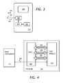
- FIG. 3is a block diagram of the test instrument of FIG. 1 ;
- FIG. 4is a block diagram showing a connection between the test instrument, the test module of FIG. 2 , and a cable modem termination system (CMTS) of the cable network of FIG. 1 ;
- CMTScable modem termination system
- FIG. 5is a block diagram of a test system for testing the upstream path according to an embodiment of the invention, showing flow of commands between modules of the system;
- FIG. 6is a block diagram of upstream packet pre-filtering apparatus according to an embodiment of the invention.
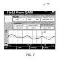
- FIG. 7is an example view of a display of the test instrument, showing signal quality information
- a cable network 100includes a headend 101 , a plurality of nodes 102 , and a plurality of terminal devices 104 .
- a cable plant 106connects the terminal devices 104 to the respective nodes 102 , and the nodes 102 to the headend 101 .
- the terminal devices 104can include digital TV boxes, VoIP phone systems, and cable modems.
- the headendsends downstream signals 108 to the terminal devices 104 through the cable plant 106 .
- the downstream signals 110include TV broadcasting signals, as well as DOCSIS downstream data packets and control signals.
- the terminal devices 104send upstream signals 110 , for example DOCSIS upstream data bursts.
- the test module 121includes a communication circuit 202 for receiving the test request 112 and the upstream data packet 124 , a demodulator 204 coupled to the communication circuit 202 , for demodulating the upstream data packet 124 , and a processor 206 coupled to the demodulator 204 and to the communication circuit 202 , for calculating signal quality parameters of the demodulated upstream data packet and for sending, through the communication circuit 202 , signal quality information 128 back to the test instrument 111 .
- the pre-equalization coefficientsare stored in a database 129 located at the headend 101 .
- the database 129associates the terminal devices 104 connected to the cable network 100 with pre-equalization coefficients that have been sent by the cable modem termination system (CMTS) of the headend 101 to the terminal devices 104 for use in generation of the upstream transmission signals 110 .
- CMTScable modem termination system
- Upstream signal pre-equalizationis known to a person skilled in the art to be a part of the DOCSIS communication protocol.
- the pre-equalization coefficientscan be obtained from the database 129 .
- the pre-equalization coefficientscan be supplied by the test instrument 111 .
- the pre-equalization coefficientscan be included in the payload of the upstream data packet 124 . After demodulation of the upstream data packet 124 , these coefficients will be obtained by the processor 206 , which can use them to correct the signal quality information 128 for pre-equalization.
- the test instrument 111establishes a line of communication 402 with the test module 121 .
- the test module 121performs measurements 406 of various signals in a CMTS 404 , to obtain the signal quality data.
- the line of communication 402can be formed based on a service DOCSIS channel, an out-of-band (OOB) service channel, or, if time permits to make such a connection, a separate regular DOCSIS bidirectional communications channel.
- OOBout-of-band
- the test instrument 111To perform signal quality measurements, the test instrument 111 first establishes a regular DOCSIS communication channel with the CMTS 404 , as indicated by “Establish DOCSIS” command 504 . Then, the test instrument 111 opens a TCP/IP communications session with an interoperations server 502 , as indicated by “Open Interoperation Session” command 506 .
- the interoperations server 502is a Web based application that uses a standard Web browser to communicate with the test instrument 111 .
- the interoperations server 502provides the test instrument 111 with a list of currently active nodes 102 of the cable network 100 .
- pre-filtering of upstream data packets at the headendis used to improve speed and reliability of detecting and processing the upstream data packets 124 sent by the test instrument 111 .
- a pre-filtering apparatus 600is a part of the test module 121 .
- the pre-filtering apparatus 600includes a packet duration filter 602 , the demodulator 204 , a MAC filter 604 , and the processor 206 .
- the packet duration filter 602filters the upstream traffic 110 , passing through packets having a duration of the upstream packet 124 .
- the upstream packet 124 generated by the test instrument 111passes through the packet duration filter 602 and is demodulated by the demodulator 204 .
- Packet length pre-filteringcan result in a dramatic improvement of the filtering speed. For example, at an upstream packet rate of 1000 data packets per second, plus 50 packets per second generated by the test instrument 111 , and at 100 millisecond demodulation time by the demodulator 204 of the test module 121 , the test module 121 will miss 99% of data packets, so that only one test data packet 124 from the test instrument 111 will be detected every two seconds. When the packet length pre-filtering is implemented with 99% efficiency, approximately only 10 packets out of the 1000 unwanted packets will be demodulated, which results in 60 packets per second traffic arriving at the input of the demodulator 204 .
- FIG. 7an example view 700 of the display 308 of the test instrument 111 is presented.
- the MER and the pre-equalized MER(“UnEQ MER”) are equal to each other and are equal to 20 dB.
- the in-band responseshows a spectral ripple 702 .
- a method of testing the upstream path 110 of the cable network 100is presented.
- the request 112is sent from the test instrument 111 to the test module 121 of the headend 101 to demodulate and obtain signal quality information of the upstream data packet 124 generated by the test instrument 111 .
- any one of the terminal devices 104can also be selected at this step.
- the device to receiving the packet 124 fromis identified by a device identifier selectable by the test instrument.
- QAM quality informationcan be included in the signal quality information 128 .
- the signal quality information 128may be communicated to the test instrument 111 in a variety of ways, for example by using a dedicated DOCSIS downstream channel, or by using a DOCSIS service channel.
- the step 806 of receiving and demodulating the upstream data packet 124preferably includes a step of pre-filtering upstream data packets based on the packet length, as explained above, so that only upstream data packets having the target packet length are selected for the time-consuming step of demodulation.
- the target packet lengthis selected by obtaining a probability distribution of upstream packet lengths in the cable network, and selecting a packet length having a probability of no more than a certain value, preferably 25%, of a maximum probability of the probability distribution, as the target packet length.
- the target packet lengthhas to be selected out of the set of lengths allowed by the CMTS 404 according to DOCSIS communications protocol.
- the test instrumentis configured for generating the upstream data packets 124 of a target packet length periodically, that is, at regular time intervals.
- the upstream traffic 110is filtered based on arrival time of the upstream data packets of the target packet length, thereby identifying the upstream data packets generated by the test instrument at the regular time intervals.
- the functionality of upstream packet pre-filtering based on the arrival time or frequency of the upstream data packets 124 generated by the test instruments 111can be used to automatically discover and register the test instrument 111 at the headend 101 of the cable network 100 .
- the test instrument 111sends a command to the test module 121 to pre-filter upstream data packets based on the packet length and arrival time (or frequency). This pre-filtering is performed before demodulation and thus can be done quickly and efficiently.
- the pre-filtered upstream data packets 124are analyzed for a device ID. If all of them have the same device ID, it is taken to be the ID of the test instrument.
Landscapes
- Engineering & Computer Science (AREA)
- Computer Networks & Wireless Communication (AREA)
- Signal Processing (AREA)
- Physics & Mathematics (AREA)
- Electromagnetism (AREA)
- Data Mining & Analysis (AREA)
- Quality & Reliability (AREA)
- Data Exchanges In Wide-Area Networks (AREA)
- Maintenance And Management Of Digital Transmission (AREA)
Abstract
Description
Claims (12)
Priority Applications (3)
| Application Number | Priority Date | Filing Date | Title |
|---|---|---|---|
| US13/174,272US9450686B2 (en) | 2011-06-30 | 2011-06-30 | Testing an upstream path of a cable network |
| US15/262,875US10063454B2 (en) | 2011-06-30 | 2016-09-12 | Testing an upstream path of a cable network |
| US16/107,318US10873522B2 (en) | 2011-06-30 | 2018-08-21 | Testing an upstream path of a cable network |
Applications Claiming Priority (1)
| Application Number | Priority Date | Filing Date | Title |
|---|---|---|---|
| US13/174,272US9450686B2 (en) | 2011-06-30 | 2011-06-30 | Testing an upstream path of a cable network |
Related Child Applications (1)
| Application Number | Title | Priority Date | Filing Date |
|---|---|---|---|
| US15/262,875ContinuationUS10063454B2 (en) | 2011-06-30 | 2016-09-12 | Testing an upstream path of a cable network |
Publications (2)
| Publication Number | Publication Date |
|---|---|
| US20130003565A1 US20130003565A1 (en) | 2013-01-03 |
| US9450686B2true US9450686B2 (en) | 2016-09-20 |
Family
ID=47390585
Family Applications (3)
| Application Number | Title | Priority Date | Filing Date |
|---|---|---|---|
| US13/174,272Active2033-06-02US9450686B2 (en) | 2011-06-30 | 2011-06-30 | Testing an upstream path of a cable network |
| US15/262,875ActiveUS10063454B2 (en) | 2011-06-30 | 2016-09-12 | Testing an upstream path of a cable network |
| US16/107,318Active2031-08-06US10873522B2 (en) | 2011-06-30 | 2018-08-21 | Testing an upstream path of a cable network |
Family Applications After (2)
| Application Number | Title | Priority Date | Filing Date |
|---|---|---|---|
| US15/262,875ActiveUS10063454B2 (en) | 2011-06-30 | 2016-09-12 | Testing an upstream path of a cable network |
| US16/107,318Active2031-08-06US10873522B2 (en) | 2011-06-30 | 2018-08-21 | Testing an upstream path of a cable network |
Country Status (1)
| Country | Link |
|---|---|
| US (3) | US9450686B2 (en) |
Cited By (2)
| Publication number | Priority date | Publication date | Assignee | Title |
|---|---|---|---|---|
| US10554866B2 (en)* | 2017-11-16 | 2020-02-04 | Viavi Solutions, Inc. | Methods for locating a noise source in a CATV system |
| US10728595B2 (en) | 2016-06-07 | 2020-07-28 | Viavi Solutions Inc. | Upstream sweep test with sweep server signaling |
Families Citing this family (28)
| Publication number | Priority date | Publication date | Assignee | Title |
|---|---|---|---|---|
| US9088355B2 (en) | 2006-03-24 | 2015-07-21 | Arris Technology, Inc. | Method and apparatus for determining the dynamic range of an optical link in an HFC network |
| US9021086B2 (en)* | 2011-10-21 | 2015-04-28 | Comcast Cable Communications, Llc | System and method for network management |
| US8837302B2 (en)* | 2012-04-27 | 2014-09-16 | Motorola Mobility Llc | Mapping a network fault |
| US8868736B2 (en) | 2012-04-27 | 2014-10-21 | Motorola Mobility Llc | Estimating a severity level of a network fault |
| US8867371B2 (en)* | 2012-04-27 | 2014-10-21 | Motorola Mobility Llc | Estimating physical locations of network faults |
| CA2887484C (en) | 2012-10-15 | 2018-07-31 | Trilithic, Inc. | Icon-based home certification, in-home leakage testing, and antenna matching pad |
| US10764532B2 (en) | 2012-10-30 | 2020-09-01 | Viavi Solutions Inc. | Method and system for locating ingress utilizing customer premises equipment |
| US9197886B2 (en) | 2013-03-13 | 2015-11-24 | Arris Enterprises, Inc. | Detecting plant degradation using peer-comparison |
| US10477199B2 (en) | 2013-03-15 | 2019-11-12 | Arris Enterprises Llc | Method for identifying and prioritizing fault location in a cable plant |
| US9042236B2 (en) | 2013-03-15 | 2015-05-26 | Arris Technology, Inc. | Method using equalization data to determine defects in a cable plant |
| US9025469B2 (en) | 2013-03-15 | 2015-05-05 | Arris Technology, Inc. | Method for estimating cable plant topology |
| US10623809B2 (en)* | 2014-08-22 | 2020-04-14 | Viavi Solutions, Inc. | CATV return band sweeping using data over cable service interface specification carrier |
| US9729257B2 (en)* | 2014-09-24 | 2017-08-08 | Cable Television Laboratories, Inc. | Isolating an upstream noise source in a cable television network |
| CN104297802B (en)* | 2014-09-24 | 2017-12-05 | 国家电网公司 | A kind of cable line tester |
| US9237040B1 (en)* | 2015-03-10 | 2016-01-12 | Cisco Technologies, Inc. | Pre-equalization enhancement for telecommunication networks |
| CN108141379B (en)* | 2015-09-15 | 2021-07-13 | 昕诺飞控股有限公司 | Supply of wireless devices without keypads |
| US11418450B2 (en)* | 2016-05-27 | 2022-08-16 | Vecima Networks Inc. | Upstream channels for distributed CMTS |
| US11121938B2 (en)* | 2016-09-14 | 2021-09-14 | Telecom Italia S.P.A. | Performance measurement in a packet-switched communication network |
| US10594555B2 (en)* | 2016-12-16 | 2020-03-17 | Intelligent Platforms, Llc | Cloud-enabled testing of control systems |
| US11323353B1 (en) | 2016-12-30 | 2022-05-03 | Wells Fargo Bank, N.A. | Assessing system effectiveness |
| US10411988B1 (en)* | 2016-12-30 | 2019-09-10 | Wells Fargo Bank, N.A. | Data injection testing |
| US10181997B2 (en)* | 2017-03-06 | 2019-01-15 | Keysight Technologies Singapore (Holdings) Pte. Ltd. | Methods, systems and computer readable media for providing receive port resiliency in a network equipment test device |
| US10707917B2 (en) | 2017-11-08 | 2020-07-07 | Viavi Solutions, Inc. | Instrument, system, and method for locating a leakage source |
| US10715212B2 (en) | 2018-05-10 | 2020-07-14 | Viavi Solutions Inc. | Instruments and methods of detecting intermittent noise in a cable network system |
| CN109861880B (en)* | 2019-01-23 | 2021-03-12 | 四川虹美智能科技有限公司 | Production detection method and device of wireless communication module |
| US10958485B1 (en)* | 2019-12-11 | 2021-03-23 | Viavi Solutions Inc. | Methods and systems for performing analysis and correlation of DOCSIS 3.1 pre-equalization coefficients |
| US11888539B1 (en) | 2021-02-24 | 2024-01-30 | Veex Inc. | On demand frequency testing |
| CA3175654A1 (en)* | 2021-09-17 | 2023-03-17 | Comcast Cable Communications, Llc | Network management for band splits |
Citations (35)
| Publication number | Priority date | Publication date | Assignee | Title |
|---|---|---|---|---|
| US5790523A (en) | 1993-09-17 | 1998-08-04 | Scientific-Atlanta, Inc. | Testing facility for a broadband communications system |
| WO2000013424A1 (en) | 1998-09-02 | 2000-03-09 | Wavetek Wandel Goltermann, Inc. | Catv return path impairment detection and location system |
| US20020019983A1 (en) | 2000-06-05 | 2002-02-14 | Emsley Brett W. | Testing instrument |
| US6370163B1 (en)* | 1998-03-11 | 2002-04-09 | Siemens Information And Communications Network, Inc. | Apparatus and method for speech transport with adaptive packet size |
| US6425132B1 (en) | 1998-04-06 | 2002-07-23 | Wavetek Corporation | Ingress testing of CATV system utilizing remote selection of CATV node |
| US20020136165A1 (en)* | 2001-03-23 | 2002-09-26 | Roger Ady | Cable modem with autonomous diagnostic function |
| US20030126255A1 (en) | 2001-11-26 | 2003-07-03 | Rice Daniel J. | Network performance parameterizing |
| US6650698B1 (en)* | 1999-09-29 | 2003-11-18 | Conexant Systems, Inc. | Non-linear equalization for the upstream data connection of 56K PCM modems |
| US20040073937A1 (en)* | 2002-09-30 | 2004-04-15 | Williams Thomas H. | System and method to test network performance with impairments |
| US20040088733A1 (en) | 2002-11-04 | 2004-05-06 | Havens Daniel W. | Broadband network test system and method |
| US6791995B1 (en)* | 2002-06-13 | 2004-09-14 | Terayon Communications Systems, Inc. | Multichannel, multimode DOCSIS headend receiver |
| US20040244043A1 (en)* | 2003-05-28 | 2004-12-02 | Lind Paul Alan | Wideband DOCSIS on catv systems using port-trunking |
| US20050047442A1 (en) | 2003-08-25 | 2005-03-03 | Brady Volpe | Method and apparatus for collectively and selectively analyzing the signal integrity of individual cable modems on a DOCSIS network |
| US20050144648A1 (en)* | 2003-10-31 | 2005-06-30 | Gotwals Michael D. | Communication network analysis apparatus with internetwork connectivity |
| US7010730B1 (en) | 2000-11-01 | 2006-03-07 | Sunrise Telecom Incorporated | System and method for testing the upstream channel of a cable network |
| US7061973B1 (en)* | 2000-02-03 | 2006-06-13 | General Electric Capital Corporation | Data mode signaling system for PCM modem adaptation |
| US20070121712A1 (en)* | 2005-11-10 | 2007-05-31 | Acterna Llc | Characterizing Broadband Communication Networks |
| US20070133425A1 (en) | 2005-12-07 | 2007-06-14 | Jds Uniphase Corporation | End Of Line Monitor Using DOCSIS |
| US7403486B2 (en) | 2003-10-31 | 2008-07-22 | Acterna | Signal level measurement and data connection quality analysis apparatus and methods |
| US20080291990A1 (en)* | 2007-05-23 | 2008-11-27 | Nec Corporation | Reception quality measuring apparatus and reception quality measuring method |
| US20080291840A1 (en) | 2007-05-22 | 2008-11-27 | General Instrument Corporation | Method and Apparatus for Selecting a Network Element for Testing a Network |
| US20080298270A1 (en) | 2007-06-04 | 2008-12-04 | Acterna Llc | Upstream Signal Quality Monitoring |
| US7489641B2 (en) | 2005-04-25 | 2009-02-10 | Acterna | Data connection quality analysis apparatus and methods |
| US20090213737A1 (en) | 2008-02-21 | 2009-08-27 | Sunrise Telecom Incorporated | Test system with return sweep level setting |
| US20090271836A1 (en) | 2008-04-25 | 2009-10-29 | Ben Maxson | Testing catv networks with direct sequence spread spectrum signals |
| US20090268034A1 (en) | 2008-04-28 | 2009-10-29 | Actena Llc | Measuring the frequency response of a catv network |
| US20100080133A1 (en)* | 2006-11-06 | 2010-04-01 | Avi Oron | Media session identification method for ip networks |
| US7715437B2 (en) | 2001-09-27 | 2010-05-11 | Broadcom Corporation | Highly integrated media access control |
| US20100158093A1 (en) | 2008-12-23 | 2010-06-24 | General Instrument Corporation | Methods and System for Determining a Dominant Impairment of an Impaired Communication Channel |
| US20100157824A1 (en) | 2008-12-23 | 2010-06-24 | General Instrument Corporation | Methods and System for Determining a Dominant Impairment of an Impaired Communication Channel |
| US7792183B2 (en)* | 2006-10-12 | 2010-09-07 | Acterna Llc | Digital quality index for QAM digital signals |
| US7796526B2 (en) | 2003-10-31 | 2010-09-14 | Acterna | Versatile communication network test apparatus and methods |
| US20100309805A1 (en)* | 2009-06-04 | 2010-12-09 | Jones Jr Richard Earl | Testing upstream cable channels |
| US7873322B2 (en) | 2005-06-14 | 2011-01-18 | Acterna Llc | Ingress susceptibility on return path |
| US7885195B2 (en) | 2008-02-26 | 2011-02-08 | Sunrise Telecom Incorporated | Test system with user selectable channel |
Family Cites Families (17)
| Publication number | Priority date | Publication date | Assignee | Title |
|---|---|---|---|---|
| JPH1168849A (en)* | 1997-08-12 | 1999-03-09 | Kokusai Denshin Denwa Co Ltd <Kdd> | Traffic generator and method for determining traffic generation function |
| US6515967B1 (en)* | 1998-06-30 | 2003-02-04 | Cisco Technology, Inc. | Method and apparatus for detecting a fault in a multicast routing infrastructure |
| US7103065B1 (en)* | 1998-10-30 | 2006-09-05 | Broadcom Corporation | Data packet fragmentation in a cable modem system |
| US7177369B2 (en)* | 2001-04-27 | 2007-02-13 | Vivato, Inc. | Multipath communication methods and apparatuses |
| FR2829638B1 (en)* | 2001-09-07 | 2003-12-12 | Thales Sa | METHOD AND DEVICE FOR ANTI-INTERFERENCE, IN RECEPTION, OF A BROADBAND RADIOELECTRIC SIGNAL |
| US7362800B1 (en)* | 2002-07-12 | 2008-04-22 | Rambus Inc. | Auto-configured equalizer |
| US7333558B2 (en)* | 2003-03-31 | 2008-02-19 | Intel Corporation | Digitally pre-equalizing signals |
| US20060007999A1 (en)* | 2004-07-08 | 2006-01-12 | Gomez Ramon A | Method and system for enhancing image rejection in communications receivers using test tones and a baseband equalizer |
| US7630318B2 (en)* | 2004-12-15 | 2009-12-08 | Agilent Technologies, Inc. | Filtering wireless network packets |
| US8223830B2 (en)* | 2009-06-18 | 2012-07-17 | Agilent Technologies, Inc. | Method and apparatus for determining equalization coefficients |
| US8526485B2 (en)* | 2009-09-23 | 2013-09-03 | General Instrument Corporation | Using equalization coefficients of end devices in a cable television network to determine and diagnose impairments in upstream channels |
| US20110137991A1 (en)* | 2009-12-01 | 2011-06-09 | Lester Paul Russell | Systems and methods for management and collaboration in a private network |
| US9900406B1 (en)* | 2010-02-02 | 2018-02-20 | Arris Enterprises Llc | Method and apparatus for demand-based cable upstream channel assignment |
| US8724689B2 (en)* | 2011-03-09 | 2014-05-13 | Broadcom Corporation | Narrowband ingress estimation and characterization using equalizer taps |
| EP2552042B1 (en)* | 2011-07-28 | 2013-03-13 | Fraunhofer-Gesellschaft zur Förderung der angewandten Forschung e.V. | Demultiplexing of a packet-based transport stream |
| US9094117B1 (en)* | 2012-01-17 | 2015-07-28 | Clariphy Communications, Inc. | Channel diagnostics based on equalizer coefficients |
| US10747688B2 (en)* | 2016-12-22 | 2020-08-18 | Intel Corporation | Low latency retimer |
- 2011
- 2011-06-30USUS13/174,272patent/US9450686B2/enactiveActive
- 2016
- 2016-09-12USUS15/262,875patent/US10063454B2/enactiveActive
- 2018
- 2018-08-21USUS16/107,318patent/US10873522B2/enactiveActive
Patent Citations (36)
| Publication number | Priority date | Publication date | Assignee | Title |
|---|---|---|---|---|
| US5790523A (en) | 1993-09-17 | 1998-08-04 | Scientific-Atlanta, Inc. | Testing facility for a broadband communications system |
| US6370163B1 (en)* | 1998-03-11 | 2002-04-09 | Siemens Information And Communications Network, Inc. | Apparatus and method for speech transport with adaptive packet size |
| US6425132B1 (en) | 1998-04-06 | 2002-07-23 | Wavetek Corporation | Ingress testing of CATV system utilizing remote selection of CATV node |
| WO2000013424A1 (en) | 1998-09-02 | 2000-03-09 | Wavetek Wandel Goltermann, Inc. | Catv return path impairment detection and location system |
| US6650698B1 (en)* | 1999-09-29 | 2003-11-18 | Conexant Systems, Inc. | Non-linear equalization for the upstream data connection of 56K PCM modems |
| US7061973B1 (en)* | 2000-02-03 | 2006-06-13 | General Electric Capital Corporation | Data mode signaling system for PCM modem adaptation |
| US20020019983A1 (en) | 2000-06-05 | 2002-02-14 | Emsley Brett W. | Testing instrument |
| US7010730B1 (en) | 2000-11-01 | 2006-03-07 | Sunrise Telecom Incorporated | System and method for testing the upstream channel of a cable network |
| US20020136165A1 (en)* | 2001-03-23 | 2002-09-26 | Roger Ady | Cable modem with autonomous diagnostic function |
| US7715437B2 (en) | 2001-09-27 | 2010-05-11 | Broadcom Corporation | Highly integrated media access control |
| US20030126255A1 (en) | 2001-11-26 | 2003-07-03 | Rice Daniel J. | Network performance parameterizing |
| US6791995B1 (en)* | 2002-06-13 | 2004-09-14 | Terayon Communications Systems, Inc. | Multichannel, multimode DOCSIS headend receiver |
| US20040073937A1 (en)* | 2002-09-30 | 2004-04-15 | Williams Thomas H. | System and method to test network performance with impairments |
| US7451472B2 (en) | 2002-09-30 | 2008-11-11 | Cable Television Laboratories, Inc. | System and method to test network performance with impairments |
| US20040088733A1 (en) | 2002-11-04 | 2004-05-06 | Havens Daniel W. | Broadband network test system and method |
| US20040244043A1 (en)* | 2003-05-28 | 2004-12-02 | Lind Paul Alan | Wideband DOCSIS on catv systems using port-trunking |
| US20050047442A1 (en) | 2003-08-25 | 2005-03-03 | Brady Volpe | Method and apparatus for collectively and selectively analyzing the signal integrity of individual cable modems on a DOCSIS network |
| US7403486B2 (en) | 2003-10-31 | 2008-07-22 | Acterna | Signal level measurement and data connection quality analysis apparatus and methods |
| US7796526B2 (en) | 2003-10-31 | 2010-09-14 | Acterna | Versatile communication network test apparatus and methods |
| US20050144648A1 (en)* | 2003-10-31 | 2005-06-30 | Gotwals Michael D. | Communication network analysis apparatus with internetwork connectivity |
| US7489641B2 (en) | 2005-04-25 | 2009-02-10 | Acterna | Data connection quality analysis apparatus and methods |
| US7873322B2 (en) | 2005-06-14 | 2011-01-18 | Acterna Llc | Ingress susceptibility on return path |
| US20070121712A1 (en)* | 2005-11-10 | 2007-05-31 | Acterna Llc | Characterizing Broadband Communication Networks |
| US20070133425A1 (en) | 2005-12-07 | 2007-06-14 | Jds Uniphase Corporation | End Of Line Monitor Using DOCSIS |
| US7792183B2 (en)* | 2006-10-12 | 2010-09-07 | Acterna Llc | Digital quality index for QAM digital signals |
| US20100080133A1 (en)* | 2006-11-06 | 2010-04-01 | Avi Oron | Media session identification method for ip networks |
| US20080291840A1 (en) | 2007-05-22 | 2008-11-27 | General Instrument Corporation | Method and Apparatus for Selecting a Network Element for Testing a Network |
| US20080291990A1 (en)* | 2007-05-23 | 2008-11-27 | Nec Corporation | Reception quality measuring apparatus and reception quality measuring method |
| US20080298270A1 (en) | 2007-06-04 | 2008-12-04 | Acterna Llc | Upstream Signal Quality Monitoring |
| US20090213737A1 (en) | 2008-02-21 | 2009-08-27 | Sunrise Telecom Incorporated | Test system with return sweep level setting |
| US7885195B2 (en) | 2008-02-26 | 2011-02-08 | Sunrise Telecom Incorporated | Test system with user selectable channel |
| US20090271836A1 (en) | 2008-04-25 | 2009-10-29 | Ben Maxson | Testing catv networks with direct sequence spread spectrum signals |
| US20090268034A1 (en) | 2008-04-28 | 2009-10-29 | Actena Llc | Measuring the frequency response of a catv network |
| US20100157824A1 (en) | 2008-12-23 | 2010-06-24 | General Instrument Corporation | Methods and System for Determining a Dominant Impairment of an Impaired Communication Channel |
| US20100158093A1 (en) | 2008-12-23 | 2010-06-24 | General Instrument Corporation | Methods and System for Determining a Dominant Impairment of an Impaired Communication Channel |
| US20100309805A1 (en)* | 2009-06-04 | 2010-12-09 | Jones Jr Richard Earl | Testing upstream cable channels |
Non-Patent Citations (2)
| Title |
|---|
| JDS Uniphase Corporation, "PathTrak WebView Software", Jul. 2009, 4 pages. |
| Jim Walsh, "PathTrak QAMTrakAnalyzer Functionality", Mar. 16, 2009, pp. 1-13. |
Cited By (3)
| Publication number | Priority date | Publication date | Assignee | Title |
|---|---|---|---|---|
| US10728595B2 (en) | 2016-06-07 | 2020-07-28 | Viavi Solutions Inc. | Upstream sweep test with sweep server signaling |
| US11595710B2 (en) | 2016-06-07 | 2023-02-28 | Viavi Solutions Inc. | Upstream sweep test with sweep server signaling |
| US10554866B2 (en)* | 2017-11-16 | 2020-02-04 | Viavi Solutions, Inc. | Methods for locating a noise source in a CATV system |
Also Published As
| Publication number | Publication date |
|---|---|
| US20160380871A1 (en) | 2016-12-29 |
| US10063454B2 (en) | 2018-08-28 |
| US20190075038A1 (en) | 2019-03-07 |
| US20130003565A1 (en) | 2013-01-03 |
| US10873522B2 (en) | 2020-12-22 |
Similar Documents
| Publication | Publication Date | Title |
|---|---|---|
| US10873522B2 (en) | Testing an upstream path of a cable network | |
| US20250132986A1 (en) | Intelligent monitoring and testing system for cable network | |
| EP1717991B1 (en) | Data connection quality analysis and methods | |
| US8649421B2 (en) | Cable modem for network measurements | |
| US7403486B2 (en) | Signal level measurement and data connection quality analysis apparatus and methods | |
| US8325613B2 (en) | Characterizing broadband communication networks | |
| US7693081B1 (en) | Integrated IP DSLAM test monitor | |
| US11159414B2 (en) | Edge analytics | |
| US10764532B2 (en) | Method and system for locating ingress utilizing customer premises equipment | |
| US7860017B2 (en) | Network assessment and fault isolation | |
| US8279764B2 (en) | Method and apparatus for selecting a network element for testing a network | |
| US7796526B2 (en) | Versatile communication network test apparatus and methods | |
| US20070107034A1 (en) | Combination meter for evaluating video delivered via Internet protocol | |
| US20110001833A1 (en) | Computerized device and method for analyzing signals in a multimedia over coax alliance (moca) network and similar tdm / encrypted networks | |
| WO2007084946A2 (en) | Hierarchical communications network with upstream signal controllable from head end | |
| CN107318046B (en) | Internet television service transmission quality monitoring method and system | |
| CN110431807A (en) | The method, apparatus and system of IPTV service quality testing | |
| US20140029654A1 (en) | Method and apparatus for characterizing impulse noiseand optimizing data link efficiency | |
| US20050144648A1 (en) | Communication network analysis apparatus with internetwork connectivity | |
| CN102325060B (en) | Link bandwidth test method and router | |
| US7944848B2 (en) | Upstream signal quality monitoring | |
| US8427974B2 (en) | Identifying an origin of a DOCSIS upstream burst | |
| KR20070120257A (en) | Quality Analysis System and Analysis Method for Real-time Service in Next Generation Network | |
| Koyama et al. | Monitoring Tool for IP-based Program-production Systems in Conjunction with NMOS Control Information | |
| KR20210030169A (en) | Supporting apparatus for iptv channel monitoring, and control method thereof |
Legal Events
| Date | Code | Title | Description |
|---|---|---|---|
| AS | Assignment | Owner name:ACTERNA LLC, MARYLAND Free format text:ASSIGNMENT OF ASSIGNORS INTEREST;ASSIGNORS:GOTWALS, MICHAEL D.;JONES, DAVID W.;REEL/FRAME:026532/0277 Effective date:20110623 | |
| AS | Assignment | Owner name:JDS UNIPHASE CORPORATION, CALIFORNIA Free format text:ASSIGNMENT OF ASSIGNORS INTEREST;ASSIGNOR:ACTERNA LLC;REEL/FRAME:030968/0139 Effective date:20130627 | |
| AS | Assignment | Owner name:VIAVI SOLUTIONS INC., CALIFORNIA Free format text:CHANGE OF NAME;ASSIGNOR:JDS UNIPHASE CORPORATION;REEL/FRAME:037061/0277 Effective date:20150731 | |
| STCF | Information on status: patent grant | Free format text:PATENTED CASE | |
| FEPP | Fee payment procedure | Free format text:PAYOR NUMBER ASSIGNED (ORIGINAL EVENT CODE: ASPN); ENTITY STATUS OF PATENT OWNER: LARGE ENTITY | |
| MAFP | Maintenance fee payment | Free format text:PAYMENT OF MAINTENANCE FEE, 4TH YEAR, LARGE ENTITY (ORIGINAL EVENT CODE: M1551); ENTITY STATUS OF PATENT OWNER: LARGE ENTITY Year of fee payment:4 | |
| AS | Assignment | Owner name:WELLS FARGO BANK, NATIONAL ASSOCIATION, AS ADMINISTRATIVE AGENT, COLORADO Free format text:SECURITY INTEREST;ASSIGNORS:VIAVI SOLUTIONS INC.;3Z TELECOM, INC.;ACTERNA LLC;AND OTHERS;REEL/FRAME:052729/0321 Effective date:20200519 | |
| AS | Assignment | Owner name:RPC PHOTONICS, INC., NEW YORK Free format text:TERMINATIONS OF SECURITY INTEREST AT REEL 052729, FRAME 0321;ASSIGNOR:WELLS FARGO BANK, NATIONAL ASSOCIATION, AS ADMINISTRATIVE AGENT;REEL/FRAME:058666/0639 Effective date:20211229 Owner name:VIAVI SOLUTIONS INC., CALIFORNIA Free format text:TERMINATIONS OF SECURITY INTEREST AT REEL 052729, FRAME 0321;ASSIGNOR:WELLS FARGO BANK, NATIONAL ASSOCIATION, AS ADMINISTRATIVE AGENT;REEL/FRAME:058666/0639 Effective date:20211229 | |
| MAFP | Maintenance fee payment | Free format text:PAYMENT OF MAINTENANCE FEE, 8TH YEAR, LARGE ENTITY (ORIGINAL EVENT CODE: M1552); ENTITY STATUS OF PATENT OWNER: LARGE ENTITY Year of fee payment:8 |