US9446518B1 - Leg collision avoidance in a robotic device - Google Patents
Leg collision avoidance in a robotic deviceDownload PDFInfo
- Publication number
- US9446518B1 US9446518B1US14/538,777US201414538777AUS9446518B1US 9446518 B1US9446518 B1US 9446518B1US 201414538777 AUS201414538777 AUS 201414538777AUS 9446518 B1US9446518 B1US 9446518B1
- Authority
- US
- United States
- Prior art keywords
- foot
- swing
- stance
- robot
- determining
- Prior art date
- Legal status (The legal status is an assumption and is not a legal conclusion. Google has not performed a legal analysis and makes no representation as to the accuracy of the status listed.)
- Active, expires
Links
- 238000000034methodMethods0.000claimsdescription14
- 230000006870functionEffects0.000claimsdescription9
- 238000004519manufacturing processMethods0.000claims6
- 210000002683footAnatomy0.000description244
- 210000002414legAnatomy0.000description72
- 230000005021gaitEffects0.000description26
- 238000013500data storageMethods0.000description7
- 238000004891communicationMethods0.000description6
- 210000003127kneeAnatomy0.000description5
- 238000012544monitoring processMethods0.000description5
- 238000013461designMethods0.000description4
- 230000001133accelerationEffects0.000description3
- 238000013459approachMethods0.000description3
- 239000000463materialSubstances0.000description3
- 238000005259measurementMethods0.000description3
- 230000008569processEffects0.000description3
- 238000012545processingMethods0.000description3
- 230000004913activationEffects0.000description2
- QBWCMBCROVPCKQ-UHFFFAOYSA-Nchlorous acidChemical compoundOCl=OQBWCMBCROVPCKQ-UHFFFAOYSA-N0.000description2
- 238000012937correctionMethods0.000description2
- 230000009849deactivationEffects0.000description2
- 230000000694effectsEffects0.000description2
- 239000012530fluidSubstances0.000description2
- 210000001624hipAnatomy0.000description2
- 230000003287optical effectEffects0.000description2
- 239000007787solidSubstances0.000description2
- 210000000689upper legAnatomy0.000description2
- 206010017577Gait disturbanceDiseases0.000description1
- 210000000544articulatio talocruralisAnatomy0.000description1
- 238000002485combustion reactionMethods0.000description1
- 238000004141dimensional analysisMethods0.000description1
- 238000005516engineering processMethods0.000description1
- 238000011156evaluationMethods0.000description1
- 210000003414extremityAnatomy0.000description1
- 230000005484gravityEffects0.000description1
- 230000003993interactionEffects0.000description1
- 229910052751metalInorganic materials0.000description1
- 239000002184metalSubstances0.000description1
- 150000002739metalsChemical class0.000description1
- 230000005019pattern of movementEffects0.000description1
- 229920003023plasticPolymers0.000description1
- 239000004033plasticSubstances0.000description1
- 230000008439repair processEffects0.000description1
- 230000004044responseEffects0.000description1
- 230000000452restraining effectEffects0.000description1
- 239000011435rockSubstances0.000description1
- 239000004576sandSubstances0.000description1
- 230000001953sensory effectEffects0.000description1
- 238000012546transferMethods0.000description1
- 238000003466weldingMethods0.000description1
Images


Classifications
- B—PERFORMING OPERATIONS; TRANSPORTING
- B25—HAND TOOLS; PORTABLE POWER-DRIVEN TOOLS; MANIPULATORS
- B25J—MANIPULATORS; CHAMBERS PROVIDED WITH MANIPULATION DEVICES
- B25J9/00—Programme-controlled manipulators
- B25J9/16—Programme controls
- B25J9/1656—Programme controls characterised by programming, planning systems for manipulators
- B25J9/1664—Programme controls characterised by programming, planning systems for manipulators characterised by motion, path, trajectory planning
- B25J9/1666—Avoiding collision or forbidden zones
- B—PERFORMING OPERATIONS; TRANSPORTING
- B62—LAND VEHICLES FOR TRAVELLING OTHERWISE THAN ON RAILS
- B62D—MOTOR VEHICLES; TRAILERS
- B62D57/00—Vehicles characterised by having other propulsion or other ground- engaging means than wheels or endless track, alone or in addition to wheels or endless track
- B—PERFORMING OPERATIONS; TRANSPORTING
- B25—HAND TOOLS; PORTABLE POWER-DRIVEN TOOLS; MANIPULATORS
- B25J—MANIPULATORS; CHAMBERS PROVIDED WITH MANIPULATION DEVICES
- B25J9/00—Programme-controlled manipulators
- B25J9/16—Programme controls
- B25J9/1674—Programme controls characterised by safety, monitoring, diagnostic
- B25J9/1676—Avoiding collision or forbidden zones
- G—PHYSICS
- G05—CONTROLLING; REGULATING
- G05B—CONTROL OR REGULATING SYSTEMS IN GENERAL; FUNCTIONAL ELEMENTS OF SUCH SYSTEMS; MONITORING OR TESTING ARRANGEMENTS FOR SUCH SYSTEMS OR ELEMENTS
- G05B2219/00—Program-control systems
- G05B2219/30—Nc systems
- G05B2219/39—Robotics, robotics to robotics hand
- G05B2219/39096—Self-collision, internal collison, collision between links of one robot
- Y—GENERAL TAGGING OF NEW TECHNOLOGICAL DEVELOPMENTS; GENERAL TAGGING OF CROSS-SECTIONAL TECHNOLOGIES SPANNING OVER SEVERAL SECTIONS OF THE IPC; TECHNICAL SUBJECTS COVERED BY FORMER USPC CROSS-REFERENCE ART COLLECTIONS [XRACs] AND DIGESTS
- Y10—TECHNICAL SUBJECTS COVERED BY FORMER USPC
- Y10S—TECHNICAL SUBJECTS COVERED BY FORMER USPC CROSS-REFERENCE ART COLLECTIONS [XRACs] AND DIGESTS
- Y10S901/00—Robots
- Y10S901/01—Mobile robot
- Y—GENERAL TAGGING OF NEW TECHNOLOGICAL DEVELOPMENTS; GENERAL TAGGING OF CROSS-SECTIONAL TECHNOLOGIES SPANNING OVER SEVERAL SECTIONS OF THE IPC; TECHNICAL SUBJECTS COVERED BY FORMER USPC CROSS-REFERENCE ART COLLECTIONS [XRACs] AND DIGESTS
- Y10—TECHNICAL SUBJECTS COVERED BY FORMER USPC
- Y10S—TECHNICAL SUBJECTS COVERED BY FORMER USPC CROSS-REFERENCE ART COLLECTIONS [XRACs] AND DIGESTS
- Y10S901/00—Robots
- Y10S901/02—Arm motion controller
- Y—GENERAL TAGGING OF NEW TECHNOLOGICAL DEVELOPMENTS; GENERAL TAGGING OF CROSS-SECTIONAL TECHNOLOGIES SPANNING OVER SEVERAL SECTIONS OF THE IPC; TECHNICAL SUBJECTS COVERED BY FORMER USPC CROSS-REFERENCE ART COLLECTIONS [XRACs] AND DIGESTS
- Y10—TECHNICAL SUBJECTS COVERED BY FORMER USPC
- Y10S—TECHNICAL SUBJECTS COVERED BY FORMER USPC CROSS-REFERENCE ART COLLECTIONS [XRACs] AND DIGESTS
- Y10S901/00—Robots
- Y10S901/27—Arm part
- Y10S901/28—Joint
Definitions
- Robotic devicesmay be used for applications involving material handling, transportation, welding, assembly, and dispensing, among others.
- the manner in which these robotic systems operateis becoming more intelligent, efficient, and intuitive.
- robotic systemsbecome increasingly prevalent in numerous aspects of modern life, the desire for efficient robotic systems becomes apparent. Therefore, a demand for efficient robotic systems has helped open up a field of innovation in actuators, movement, sensing techniques, as well as component design and assembly.
- the present disclosuregenerally relates to controlling a legged robot. Specifically, implementations described herein may allow for efficient operation of a legged robot that may determine and avoid a potential leg collision between a swing leg and a stance leg.
- a first example implementationmay include (i) determining a touchdown location for a swing foot of a biped robot, the biped robot having a stance foot, where the swing foot and stance foot are each coupled to a body of the biped robot, (ii) determining a lateral position of the touchdown location relative to the stance foot, (iii) determining a lateral position of the swing foot relative to the stance foot, (iv) based on one or more of the determined lateral positions of the touchdown location and the swing foot, each relative to the stance foot, determining an intermediate swing point for the swing foot, where the intermediate swing point is not on a line defined by the swing foot and the touchdown location, (v) causing, by the biped robot, the swing foot to move to the intermediate swing point, and (vi) after causing the swing foot to move to the intermediate swing point, causing the swing foot to move to the touchdown location.
- a second example implementationmay include (i) determining a touchdown location for a swing foot of a biped robot, the biped robot having a stance foot, where the swing foot and stance foot are each coupled to a body of the biped robot, (ii) determining a forward velocity of the biped robot, (iii) determining a lateral position of the touchdown location relative to the stance foot, (v) based on the determined forward velocity of the biped robot and the determined lateral position of the touchdown location relative to the stance foot, updating the touchdown location, and (vi) causing, by the biped robot the swing foot to move to the updated touchdown location.
- a third example implementationmay include a system having means for performing operations in accordance with the first example implementation.
- a fourth example implementationmay include a system having means for performing operations in accordance with the second example implementation.
- a fifth example implementationmay include a biped robot having (i) a body, (ii) a swing foot coupled to the body, (iii) a stance foot coupled to the body, (iv) a processor; (v) a non-transitory computer readable medium; and (vi) program instructions stored on the non-transitory computer readable medium that, when executed by the processor, cause the biped robot to perform operations in accordance with the first example implementation.
- a sixth example implementationmay include a biped robot having (i) a body, (ii) a swing foot coupled to the body, (iii) a stance foot coupled to the body, (iv) a processor; (v) a non-transitory computer readable medium; and (vi) program instructions stored on the non-transitory computer readable medium that, when executed by the processor, cause the biped robot to perform operations in accordance with the second example implementation.
- FIG. 1illustrates a configuration of a robotic system, according to an example implementation.
- FIG. 2illustrates a quadruped robot, according to an example implementation.
- FIG. 3illustrates another quadruped robot, according to an example implementation.
- FIG. 4illustrates a biped robot, according to an example implementation.
- FIG. 5is a flowchart according to an example implementation.
- FIG. 6Aillustrates a swing foot and a stance foot of a robot, according to an example implementation.
- FIG. 6Billustrates the swing foot and the stance foot of the robot, according to the example implementation shown in FIG. 6A .
- FIG. 7Aillustrates the swing foot and the stance foot of the robot, according to another example implementation.
- FIG. 7Billustrates the swing foot and the stance foot of the robot, according to the example implementation shown in FIG. 7A .
- FIG. 8Aillustrates the swing foot and the stance foot of the robot, according to yet another example implementation.
- FIG. 8Billustrates the swing foot and the stance foot of the robot, according to the example implementation shown in FIG. 8A .
- FIG. 9is a flowchart according to an example implementation.
- FIG. 10Aillustrates a swing foot and a stance foot of a robot, according to an example implementation.
- FIG. 10Billustrates the swing foot and the stance foot of the robot, according to the example implementation shown in FIG. 10A .
- Example implementationsare described herein.
- the words “example,” “exemplary,” and “illustrative”are used herein to mean “serving as an example, instance, or illustration.” Any implementation or feature described herein as being an “example,” being “exemplary,” or being “illustrative” is not necessarily to be construed as preferred or advantageous over other implementations or features.
- the example implementations described hereinare not meant to be limiting.
- the aspects of the present disclosure, as generally described herein and illustrated in the figurescan be arranged, substituted, combined, separated, and designed in a wide variety of different configurations, all of which are contemplated herein.
- figuresare not drawn to scale and are used for illustrative purposes only. Moreover, the figures are representational only and not all components are shown. For example, additional structural or restraining components might not be shown.
- Example implementationsrelate to the determination and avoidance of potential leg collisions of a robot.
- the determination of potential leg collisionsmay involve determining forward and lateral positions of a swing foot and a touchdown location for the swing foot, both in relation to a stance foot. Avoiding a potential leg collision may involve adjusting a swing path of the swing foot, and/or updating the touchdown location.
- an example robotmay determine potential collisions of its legs by monitoring, via received sensor data, the movement and position of each of the links and joints in both of its legs. This may allow the robot to determine potential collisions between each of these components. For instance, the robot may monitor the trajectory of the robot's right knee in relation to the robot's left thigh, left knee, left shin, and left foot, and may do the same for the robot's right thigh, right shin, right foot, and so forth. This may result in a relatively large computational demand on the processor(s) of the robot.
- determining corrective measures to avoid the potential collisionmay also require a relatively large amount of processor capacity and time. For example, altering the trajectory of a swing leg to avoid one joint-joint or joint-link collision might not ensure that all determined collisions have been avoided. Thus, the robot may need to determine multiple possible corrections simultaneously. Nonetheless, this approach may be desirable in some applications, where relatively large gait disturbances, such as adductions or abductions of the legs, may be possible.
- the determination of potential leg collisionsmay be simplified based on the morphology of the robot.
- the joints of the robot's swing legmay maintain a relatively constant relationship during most gaits, such that the hip, knee, and foot remain in approximately the same plane, which may be referred to as a swing plane.
- the hip, knee, and foot of the stance legmay remain in approximately the same stance plane.
- these planesmay rotate about the respective hips of the robot as the feet move laterally, the hips of the robot remain a fixed distance from each other. Therefore, as the feet approach a collision, the distance between the two planes increases in the direction of the robot's hips.
- the robotmay simplify its determination of potential leg collisions by determining only the relative forward and lateral positions of its feet. This simplified approach to determining potential leg collisions may be less complex, and therefore require less computation and a lower processor demand, while retaining the same operation and achieving the same outcome.
- the biped robot in a walking gaitmay include a stance foot (e.g., the left foot) and a swing foot (e.g., the right foot) for a given step.
- the biped robotmay determine a desired touchdown location for the swing foot, and may further determine the lateral positions of the determined touchdown location and the swing foot, each relative to the stance foot. If the biped robot determines that one or both of (i) the position of the determined touchdown location or (ii) the position of the swing foot is laterally outside of (e.g., to the left of) the stance foot, a leg collision may potentially occur.
- the biped robotmay monitor the forward position of the swing foot relative to the stance foot, which may allow the biped robot to further simplify the leg collision monitoring. For example, when the biped robot determines that the swing foot has moved forward past the front of the stance foot, the biped robot may discontinue the lateral collision monitoring described above, as a leg collision is no longer likely. This may further reduce the computation and processor demand for leg collision monitoring while retaining the same operation and achieving the same outcome.
- the robotmay also determine a gait correction to avoid the collision by considering only the forward and lateral positions of the feet. For example, the biped robot may determine an intermediate swing point for the swing foot. The intermediate swing point may be approximately located at one of the medial corners of the stance foot. The biped robot may then cause the swing foot to move to the intermediate swing point. After reaching the intermediate swing point, the swing foot may be clear of the stance foot, and thus the biped robot may cause the swing foot to move to the originally determined touchdown location. Thus, the biped robot may accomplish both operations of determining a potential leg collision and avoiding the leg collision by reducing a three-dimensional system to a two-dimensional analysis.
- the biped robotmay determine an expanded footprint for one or both of the feet to further avoid leg collisions.
- the stance footmay have a given footprint based on the structure of the foot.
- the biped robotmay determine an expanded footprint that is larger than the structural footprint of the foot, and then determine the relative lateral positions of the swing foot, stance foot, and touchdown location, as well as the intermediate swing point(s), based on the expanded footprint.
- FIG. 1illustrates an example configuration of a robotic system.
- the robotic system 100represents an example robotic system configured to perform the implementations described herein. Additionally, the robotic system 100 may be configured to operate autonomously, semi-autonomously, and/or using directions provided by user(s), and may exist in various forms, such as a biped robot or a quadruped robot, among other examples. Furthermore, the robotic system 100 may also be referred to as a robotic device, mobile robot, or robot, among others.
- the robotic system 100may include processor(s) 102 , data storage 104 , program instructions 106 , and controller(s) 108 , which together may be part of a control system 118 .
- the robotic system 100may also include sensor(s) 112 , power source(s) 114 , mechanical components 110 , and electrical components 116 .
- the robotic system 100is shown for illustration purposes as robotic system 100 and may include more or less components within various examples.
- the components of robotic system 100may be connected in any manner, including wired or wireless connections, etc. Further, in some examples, components of the robotic system 100 may be positioned on multiple entities rather than a single entity. Other example illustrations of robotic system 100 may exist.
- Processor(s) 102may operate as one or more general-purpose processors or special purpose processors (e.g., digital signal processors, application specific integrated circuits, etc.).
- the processor(s) 102may be configured to execute computer-readable program instructions 106 that are stored in the data storage 104 and are executable to provide the operations of the robotic system 100 described herein.
- the program instructions 106may be executable to provide functionality of controller(s) 108 , where the controller(s) 108 may be configured to cause activation and deactivation of the mechanical components 110 and the electrical components 116 .
- the data storage 104may exist as various types of storage configured to hold memory.
- the data storage 104may include or take the form of one or more computer-readable storage media that can be read or accessed by processor(s) 102 .
- the one or more computer-readable storage mediacan include volatile and/or non-volatile storage components, such as optical, magnetic, organic or other memory or disc storage, which can be integrated in whole or in part with processor(s) 102 .
- the data storage 104can be implemented using a single physical device (e.g., one optical, magnetic, organic or other memory or disc storage unit), while in other implementations, the data storage 104 can be implemented using two or more physical devices, which may communicate via wired or wireless communication.
- the data storage 104may include additional data such as diagnostic data, among other possibilities.
- the robotic system 100may include at least one controller 108 , which may interface with the robotic system 100 .
- the controller 108may serve as a link between portions of the robotic system 100 , such as a link between mechanical components 110 and/or electrical components 116 .
- the controller 108may serve as an interface between the robotic system 100 and another computing device.
- the controller 108may serve as an interface between the robotic system 100 and a user(s).
- the controller 108may include various components for communicating with the robotic system 100 , including a joystick(s), buttons, among others.
- the example interfaces and communications noted abovemay be implemented via a wired or wireless connection, or both.
- the controller 108may perform other functions for the robotic system 100 as well. Other examples of controllers may exist.
- Mechanical components 110represent possible hardware of the robotic system 100 that may enable the robotic system 100 to operate and perform physical operations.
- the robotic system 100may include actuator(s), extendable leg(s) (“legs”), arm(s), wheel(s), one or more structured bodies for housing the computing system or other components, and other mechanical components.
- the mechanical components 110may depend on the design of the robotic system 100 and may also be based on the functions and/or tasks the robotic system 100 may be configured to perform. As such, depending on the operation and functions of the robotic system 100 , different mechanical components 110 may be available for the robotic system 100 to utilize.
- the robotic system 100may be configured to add and/or remove mechanical components 110 , which may involve assistance from a user and/or other robot.
- the robotic system 100may be initially configured with four legs, but may be altered by a user or the robotic system 100 to remove two of the four legs to operate as a biped.
- Other examples of mechanical components 110may be included within some implementations.
- the robotic system 100may include one or more sensor(s) 112 arranged to sense aspects of the robotic system 100 .
- the sensor(s) 112may include one or more force sensors arranged to measure load on various components of the robotic system 100 .
- the sensor(s) 112may include one or more force sensors on each leg. Such force sensors on the legs may measure the load on the actuators that move one or more members of the legs.
- the sensor(s) 112may further include one or more position sensors. Position sensors may sense the position of the actuators of the robotic system. In one implementation, position sensors may sense the extension, retraction, or rotation of the actuators on the legs of the robot.
- the sensor(s) 112may further include one or more velocity and/or acceleration sensors.
- the sensor(s) 112may include an inertial measurement unit (IMU). The IMU may sense velocity and acceleration in the world frame, with respect to the gravity vector. The velocity and acceleration of the IMU may then be translated to the robotic system, based on the location of the IMU in the robotic system and the kinematics of the robotic system.
- Other sensor(s) 112are also possible, including proximity sensors, motion sensors, load sensors, touch sensors, depth sensors, ultrasonic range sensors, and infrared sensors, among other possibilities.
- the sensor(s) 112may provide sensor data to the processor(s) 102 to allow for appropriate interaction of the robotic system 100 with the environment as well as monitoring of operation of the systems of the robotic system 100 .
- the sensor datamay be used in evaluation of various factors for activation and deactivation of mechanical components 110 and electrical components 116 by controller 108 and/or a computing system of the robotic system 100 .
- the sensor(s) 112may provide information indicative of the environment of the robot for the controller 108 and/or computing system to use to determine operations for the robotic system 100 .
- the sensor(s) 112may capture data corresponding to the terrain of the environment or location of nearby objects, which may assist with environment recognition and navigation, etc.
- the robotic system 100may include a sensor system that includes RADAR, LIDAR, SONAR, VICON®, one or more cameras, a global positioning system (GPS) transceiver, and/or other sensors for capturing information of the environment of the robotic system 100 .
- the sensor(s) 112may monitor the environment in real-time and detect obstacles, elements of the terrain, weather conditions, temperature, and/or other parameters of the environment for the robotic system 100 .
- the robotic system 100may include other sensor(s) 112 configured to receive information indicative of the state of the robotic system 100 , including sensor(s) 112 that may monitor the state of the various components of the robotic system 100 .
- the sensor(s) 112may measure activity of systems of the robotic system 100 and receive information based on the operation of the various features of the robotic system 100 , such the operation of extendable legs, arms, or other mechanical and/or electrical features of the robotic system 100 .
- the sensor data provided by the sensorsmay enable the computing system of the robotic system 100 to determine errors in operation as well as monitor overall functioning of components of the robotic system 100 .
- the computing systemmay use sensor data to determine a stability of the robotic system 100 during operations as well as measurements related to power levels, communication activities, components that require repair, among other information.
- the robotic system 100may include gyroscope(s), accelerometer(s), and/or other possible sensors to provide sensor data relating to the state of operation of the robot.
- sensor(s) 112may also monitor the current state of a function, such as a gait, that the robotic system 100 may currently be operating. Other example uses for the sensor(s) 112 may exist as well.
- the robotic system 100may also include one or more power source(s) 114 configured to supply power to various components of the robotic system 100 .
- the robotic system 100may include a hydraulic system, electrical system, batteries, and/or other types of power systems.
- the robotic system 100may include one or more batteries configured to provide charge to components that may receive charge via a wired and/or wireless connection.
- components of the mechanical components 110 and electrical components 116may each connect to a different power source or may be powered by the same power source.
- Components of the robotic system 100may connect to multiple power sources 114 as well.
- any type of power sourcemay be used to power the robotic system 100 , such as a gasoline engine.
- the power source(s) 114may charge using various types of charging, such as wired connections to an outside power source, wireless charging, combustion, or other examples.
- the robotic system 100may include a hydraulic system configured to provide power to the mechanical components 110 using fluid power. Components of the robotic system 100 may operate based on hydraulic fluid being transmitted throughout the hydraulic system to various hydraulic motors and hydraulic cylinders, for example. The hydraulic system of the robotic system 100 may transfer a large amount of power through small tubes, flexible hoses, or other links between components of the robotic system 100 . Other power sources may be included within the robotic system 100 within examples.
- the electrical components 116may include various components capable of processing, transferring, providing electrical charge or electric signals, for example.
- the electrical components 116may include electrical wires, circuitry, and/or wireless communication transmitters and receivers to enable operations of the robotic system 100 .
- the electrical components 116may interwork with the mechanical components 110 to enable the robotic system 100 to perform various functions.
- the electrical components 116may be configured to provide power from the power source(s) 114 to the various mechanical components 110 , for example.
- the robotic system 100may include electric motors. Other examples of electrical components 116 may exist as well.
- FIG. 2illustrates an example quadruped robot 200 , according to an example implementation.
- the robot 200may be configured to perform some of the methods described herein during operation.
- the robot 200includes a control system 202 , and legs 204 a , 204 b , 204 c , 204 d connected to a body 208 .
- Each legmay include a respective foot 206 a , 206 b , 206 c , 206 d that may contact the ground surface.
- the robot 200may also include sensors (e.g., sensor 210 ) configured to provide sensor data to the control system 202 of the robot 200 .
- the robot 200is illustrated carrying a load 212 on the body 208 .
- the robot 200may include more or less components and may additionally include components not shown in FIG. 2 .
- the robot 200may be a physical representation of the robotic system 100 shown in FIG. 1 or may be based on other configurations.
- the robot 200includes a computing system that may be made up of one or more computing devices configured to assist in various operations of the robot 200 , which may include processing data and providing outputs based on the data.
- the computing systemmay process information provided by various systems of the robot 200 (e.g., a sensor system) or from other sources (e.g., a user, another robot, a server) and may provide instructions to the systems to operate in response.
- the computing systemmay monitor systems of the robot 200 during operation, to determine errors and/or monitor regular operation, for example.
- the computing systemmay serve as a connection between the various systems of the robot 200 that coordinates the operations of the systems together to enable the robot 200 to perform functions.
- the operations described hereincorrespond to a computing system of a robot performing tasks, the computing system may be made of multiple devices, processors, controllers, and/or other entities configured to assist in the operation of the robot. Additionally, the computing system may operate using various types of memory and/or other components.
- the robot 200may include more or less legs within other examples.
- the configuration, position, and/or structure of the legs 204 a - 204 dmay vary in example implementations.
- the legs 204 a - 204 denable the robot 200 to move and may be configured to operate in multiple degrees of freedom to enable different techniques of travel to be performed.
- the legs 204 a - 204 dmay enable the robot 200 to travel at various speeds through mechanically controlling the legs 204 a - 204 d according to the mechanics set forth within different gaits.
- a gaitis a pattern of movement of the limbs of an animal, robot, or other mechanical structure.
- the robot 200may navigate by operating the legs 204 a - 204 d to perform various gaits.
- the robot 200may use one or more gaits to travel within an environment, which may involve selecting a gait based on speed, terrain, the need to maneuver, and/or energy efficiency.
- gaitsmay use different gaits due to differences in design that may prevent use of certain gaits. Although some gaits may have specific names (e.g., walk, trot, run, bound, gallop, etc.), the distinctions between gaits may overlap. The gaits may be classified based on footfall patterns—the locations on the ground surface for the placement the feet 206 a - 206 d . Similarly, gaits may also be classified based on mechanics.
- One or more systems of the robot 200may be configured to operate the legs 204 a - 204 d to cause the robotic 200 to move.
- the robot 200may include other mechanical components, which may be attached to the robot 200 at various positions.
- the robot 200may include mechanical arms, grippers, or other features.
- the legs 204 a - 204 dmay have other types of mechanical features that enable control upon various types of surfaces that the robot may encounter, such as wheels, etc. Other possibilities also exist.
- the body 208 of the robot 200connects to the legs 204 a - 204 d and may house various components of the robot 200 .
- the structure of the body 208may vary within examples and may further depend on particular operations that a given robot may have been designed to perform. For example, a robot developed to carry heavy loads may have a wide body that enables placement of the load. Similarly, a robot designed to reach high speeds may have a narrow, small body that does not have substantial weight.
- the body 208 as well as the legs 204may be developed using various types of materials, such as various metals or plastics. Within other examples, a robot may have a body with a different structure or made of other types of materials.
- the sensor(s) 210 of the robot 200may include various types of sensors, such as the camera or sensing system shown in FIG. 2 .
- the sensor(s) 210is positioned on the front of the body 208 , but may be placed at other positions of the robot as well.
- the robot 200may include a sensory system that includes force sensors, position sensors, IMUs, RADAR, LIDAR, SONAR, VICON®, GPS, accelerometer(s), gyroscope(s), and/or other types of sensors.
- the sensor(s) 210may be configured to measure parameters of the environment of the robot 200 as well as monitor internal operations of systems of the robot 200 .
- the robot 200may include sensors that monitor the accuracy of its systems to enable the computing system to detect a system within the robot 100 that may be operating incorrectly. Other uses of the sensor(s) 210 may be included within examples.
- the load 212 carried by the robot 200may represent various types of cargo that the robot 200 may transport.
- the load 212may also represent external batteries or other types of power sources (e.g., solar panels) that the robot 200 may utilize.
- the load 212represents one example use for which the robot 200 may be configured.
- the robot 200may be configured to perform other operations as well.
- the robot 200may also include various electrical components that may enable operation and communication between the mechanical features of the robot 200 .
- the robot 200may include one or more computing systems that include one or more processors configured to perform various operations, including processing inputs to provide control over the operation of the robot 200 .
- the computing systemmay include additional components, such as various types of storage and a power source, etc.
- the computing systemmay communicate with other systems of the robot 200 via wired or wireless connections and may further be configured to communicate with one or more users of the robot.
- the computing systemmay receive an input from a user indicating that the user wants the robot to perform a particular gait in a given direction.
- the computing systemmay process the input and may perform an operation that may cause the systems of the robot to perform the requested gait.
- the robot's electrical componentsmay include interfaces, wires, busses, and/or other communication links configured to enable systems of the robot to communicate.
- the robot 200may communicate with one or more users and/or other robots via various types of interfaces.
- the robot 200may receive input from a user via a joystick or similar type of interface.
- the computing systemmay be configured to measure the amount of force and other possible information from inputs received from a joystick interface.
- the robot 200may receive inputs and communicate with a user via other types of interfaces, such as a mobile device or a microphone.
- the computing system of the robot 200may be configured to process various types of inputs.
- FIG. 3illustrates another quadruped robot 300 according to an example implementation. Similar to robot 200 shown in FIG. 2 , the robot 300 may correspond to the robotic system 100 shown in FIG. 1 .
- the robot 300serves as another possible example of a robot that may be configured to perform some of the implementations described herein.
- FIG. 4illustrates a biped robot 400 according to another example implementation. Similar to robots 200 and 300 shown in FIGS. 2 and 3 , the robot 400 may correspond to the robotic system 100 shown in FIG. 1 , and may be configured to perform some of the implementations described herein. The robot 400 may include more or less components than those shown in FIG. 2 and discussed with respect to the robot 200 . For example, the robot 400 may include a control system 401 and legs 402 , 403 connected to a body 404 . Each leg may include a respective foot 405 , 406 , that may contact the ground surface. The robot 400 may also include sensors (e.g., sensor 407 ) configured to provide sensor data to the control system 401 of the robot 400 .
- sensorse.g., sensor 407
- Flow charts 500 and 900shown in FIGS. 5 and 9 respectively, present example operations that may be implemented by a biped robot, such as the example robot 400 shown in FIG. 4 .
- Flow charts 500 and 900may include one or more operations or actions as illustrated by one or more of the blocks shown in each figure. Although the blocks are illustrated in sequential order, these blocks may also be performed in parallel, and/or in a different order than those described herein. Also, the various blocks may be combined into fewer blocks, divided into additional blocks, and/or removed based upon the desired implementation.
- each blockmay represent a module, a segment, or a portion of program code, which includes one or more instructions executable by a processor for implementing specific logical operations.
- the program codemay be stored on any type of computer readable medium, for example, such as a storage device including a disk or hard drive.
- each blockmay represent circuitry that is wired to perform the specific logical operations.
- ground surfaceas used herein is meant to encompass any possible surface or terrain that the robot may encounter, and is not meant to be limiting.
- the ground surfacemay be indoors or outdoors, may be rigid or loose, such as sand or gravel, and may include discontinuities or irregularities such as stairs, rocks, fallen trees, debris, and the like. Numerous other examples exist.
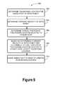
- FIG. 5is a flowchart 500 illustrating operations for determining and avoiding potential leg collisions in an example biped robot by focusing on foot collisions in two dimensions.
- the following paragraphsdiscuss a biped robot with two feet, however the operations may also be applicable to robots with a different number of feet, such as a quadruped robot with four feet, among other examples. Further, the operations discussed below may be performed by a robot that is walking, trotting, or running Other gaits are also possible.
- a biped robotmay determine a touchdown location for a swing foot that is coupled to a body of the biped robot.
- the biped robotmay be, for example, the biped robot 400 shown in FIG. 4 .
- the biped robot 400may also include a stance foot, and both the swing foot and stance foot may be coupled to a body of the robot 400 .
- the stance footmay be in contact with the ground surface, while the swing foot might not be in contact the ground surface.
- the touchdown location for the swing footrepresents a target location for the swing foot to contact the ground surface at the end of its swing trajectory. Further, the touchdown location may be determined by the robot 400 at a given frequency throughout a step, such as a frequency in the range of 1-10,000 Hz. For example, the robot may determine the touchdown location for the swing foot every five milliseconds.
- the touchdown location for a given stepmay be determined by the robot 400 based on a number of factors, such as the heading of the robot, and the current needs of the robot to maintain its balance or correct any gait errors that may have occurred. Gait errors may include a slip of the robot's foot or a collision with an obstacle, among other examples. However, in some cases the determined touchdown location may result in a swing trajectory for the swing foot that may collide with the stance leg.
- the robot 400may determine a lateral position of the touchdown location relative to the stance foot. Similarly, at block 506 , the robot 400 may determine a lateral position of the swing foot relative to the stance foot. In some cases, one or both of these may indicate that a potential collision is possible.
- the lateral positions of the robot's feetmay be determined based on data received from sensors of the robot 400 , such as position and movement sensors in the robot's legs 402 , 403 , which may provide data regarding the angles of the robot's leg joints.
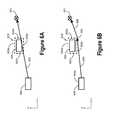
- FIG. 6Aillustrates a top view of the foot positions of the robot 400 walking from left to right in the forward (x-axis) direction.
- the stance footis the left foot 405
- the swing footis the right foot 406 , although other arrangements are possible.
- FIG. 6Aalso shows the determined touchdown location 601 .
- the robot 400may approximate the touchdown location 601 and the feet 405 , 406 as single points, without length or width.
- the stance foot 405 of the robot 400may have a footprint, shown as the solid rectangle in FIG. 6A , that is based on the structural size and shape of the foot.
- the determination of the forward (x-axis) and lateral (y-axis) positions of the feet 405 , 406 and the touchdown location 601may additionally or alternatively be based on this representation of the footprint.
- the robot 400may expand the single point or footprint representation for the stance foot 405 in order to introduce a factor of safety in avoiding leg collisions. For example, the robot 400 may determine a lateral side 602 a , a medial side 602 b , a posterior side 602 c , and an anterior side 602 d of the stance foot 405 that is each outwardly offset from the footprint such that they define an expanded footprint 602 , shown as the dashed rectangle in FIG. 6A . The robot 400 may then base the determinations of the relative lateral positions of the feet and the touchdown location 601 on the expanded footprint 602 . A similar expanded footprint may additionally or alternatively be determined for swing foot 406 .
- the distance that the expanded footprint 602 is offset from the structural footprintmay be based on a number of factors, such as the robot's configuration, gait, and velocity, among other possibilities.
- the expanded footprint 602may be offset from the structural footprint of the stance foot 405 within the range of 2-10 centimeters.
- the robot 400may determine the expanded footprint 602 disproportionately on different sides of the stance foot 405 in some cases.
- the determination of an expanded footprintmay also be used in an implementation involving a quadruped robot, and may be relatively larger, where the structural footprint of the foot may be relatively smaller than that of a biped robot. Other examples are also possible.
- the robot 400may determine that the touchdown location 601 is laterally outside of the medial side 602 b of the stance foot 405 . Because of the lateral position of the touchdown location 601 , a line 603 representing a potential swing trajectory from the swing foot 406 to the touchdown location 601 indicates a potential collision.
- the robot 400may, based on one or more of the determined lateral positions of the touchdown location 601 and the swing foot 406 , each relative to the stance foot 405 , determine an intermediate swing point 604 for the swing foot 406 .
- the intermediate swing pointrepresents a two-dimensional point through which the swing foot 406 may move without colliding with the stance foot 405 .
- the intermediate swing point 604is not on the line 603 defined by the swing foot 406 and the touchdown location 601 , so as to avoid the potential collision.
- the determination of the intermediate swing point 604is based on the lateral position of the touchdown location 601 relative to the stance foot 405 .
- the robot 400may determine the intermediate swing point 604 to be medial to the medial side 602 a of the stance foot 405 and anterior to the anterior side 602 d of the stance foot 405 .
- the intermediate swing point 604may be determined based on the expanded footprint 602 , and placed at the medial-anterior corner of the expanded footprint 602 as shown in FIG. 6B .
- other locations for the intermediate swing point 604are also possible.
- the robotmay cause the swing foot 406 to move to the intermediate swing point 604 .
- the robot 400may cause the actuators in the hip, knee, and/or ankle joints to move the robot's leg such that the trajectory of the swing foot 406 follows a line 605 from its current position to the intermediate swing point 604 .
- the robot 400may cause a medial edge 406 a of the swing foot 406 to move to the intermediate swing point 604 .
- the robotmay determine an expanded footprint, as discussed above, for the swing foot 406 , and may cause a medial side of the expanded footprint to move to the intermediate swing point 604 .
- the robot 400may determine the size of the stance foot's expanded footprint 602 based on the width of the swing foot 406 , and may cause the center of the swing foot 406 to move to the intermediate swing point 604 .
- the determination of potential leg collisions and the avoidance of the collisionsare accomplished by the robot 400 in two dimensions, by focusing on the forward and lateral positions of the touchdown location and robot's feet 405 , 406 .
- the intermediate swing point 604is a two-dimensional point, without a vertical (z-axis) component. Therefore, while the robot 400 may alter the forward and/or lateral trajectory of the swing foot 406 to cause the swing foot 406 to move to the intermediate swing point 604 , the vertical component of the swing foot's trajectory 406 (i.e., it's height off the ground surface) might not need to be adjusted.
- the robot 400may cause the swing foot 406 to move to the touchdown location 601 .
- the robot 400may cause the trajectory of the swing foot 406 to follow a line 606 from the intermediate swing point 604 to the touchdown location 601 .
- the robot 400may place the swing foot 406 in the originally determined touchdown location, while also avoiding the potential collision of its legs.
- the robot 400may repeat the operations of determining the lateral positions of the touchdown location 601 and the swing foot 406 , each relative to the stance foot 405 , at a frequency until the robot 404 detects an indication to stop repeating the operations.
- the frequencymay be within the range of 1-10,000 Hz. Other frequencies are also possible depending on the size, configuration, and gait of the robot, among other considerations.
- the robot 400may determine the relative lateral positions of its feet and the touchdown location every three milliseconds. This may allow the robot 400 to respond to disturbances that may occur during a step, while the swing foot 406 is following a determined swing trajectory. Based on the updated relative lateral positions of the feet and touchdown location, the robot 404 may also update the intermediate swing point 604 as necessary.
- the robot 400may detect an indication to stop determining the lateral positions of the touchdown location 601 and the swing foot 406 , each relative to the stance foot 405 . For example, for a given step of the robot 400 , once the swing foot 406 passes the stance foot 405 in the forward direction, a collision of the robot's legs might no longer be likely to occur. Thus, the determination of the relative lateral positions might be temporarily discontinued.
- the robot 400may determine a forward position of the swing foot 406 relative to the stance foot 405 at a given frequency.
- the indication to stop repeating the determination of relative lateral positionsmay include an indication that the forward position of the swing foot 406 is anterior to the anterior side 602 d of the stance foot 405 .
- the robot 400may then resume determining the relative lateral positions of its feet and the next touchdown location.
- the potential leg collisionmay be determined based on the lateral position of the touchdown location 601 relative to the stance foot 405 .
- a potential leg collisionmay alternatively be determined based on the lateral position of the swing foot 406 relative to the stance foot 405 .
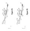
- FIG. 7Aillustrates another top view of the foot positions of the robot 400 and a touchdown location 701 , here in a different configuration.
- the robot 400may determine that the swing foot 406 is laterally outside of the medial side 602 b of the stance foot 405 . Because of the lateral position of the swing foot 406 , a line 702 representing a potential swing trajectory from the swing foot 406 to the touchdown location 701 indicates a potential collision.
- the robot 404may determine an intermediate swing point 703 for the swing foot 406 , as shown in FIG. 7B .
- the intermediate swing point 703might not be on the line 702 defined by the swing foot 406 and the touchdown location 701 , so as to avoid the potential collision. Rather, the robot 400 may determine an intermediate swing point 703 that is medial to the medial side 602 a of the stance foot 405 and posterior to the posterior side 602 c of the stance foot 405 .
- the intermediate swing point 703is shown at the medial-posterior corner of the expanded footprint 602 , however other locations are also possible.
- the robot 400may then cause the swing foot 406 to move to the intermediate swing point 703 , for example, along the line 704 .
- the robot 400may cause the medial edge 406 a of the swing foot 406 to move to the intermediate swing point 703 , among other possibilities noted above.
- the robot 400may cause the swing foot 406 to move to the touchdown location 701 .
- the robot 400may cause the trajectory of the swing foot 406 to follow a line 705 from the intermediate swing point 703 to the touchdown location 701 .
- FIG. 8Aillustrates another example configuration of the feet and touchdown location 801 for the robot 400 .
- the robot 400may determine that both the swing foot 406 and the touchdown location 801 are laterally outside of the medial side 602 b of the stance foot 405 , and thus a line 802 representing a potential swing trajectory from the swing foot 406 to the touchdown location 801 indicates a potential collision.
- the robot 400may determine two intermediate swing points, as shown in FIG. 8B .
- the robot 400may determine a first intermediate swing point 803 that is medial to the medial side 602 a of the stance foot 405 and posterior to the posterior side 602 c of the stance foot 405 .
- the robot 400may also determine a second intermediate swing point 804 that is medial to the medial side 602 a of the stance foot 405 and anterior to the anterior side 602 c of the stance foot 405 .
- the intermediate swing points 803 , 804are shown at the medial corners of the expanded footprint 602 , however other locations are possible.
- the robot 400may then cause the swing foot 406 to move to the first intermediate swing point 803 , for example, along the line 805 .
- the robot 400may cause the medial edge 406 a of the swing foot 406 to move to the intermediate swing point 805 , among other possibilities noted above.
- the robot 400may cause the swing foot 406 to move to the second intermediate swing point 804 .
- the robot 400may cause the trajectory of the swing foot 406 to follow a line 806 from the first intermediate swing point 803 to the second intermediate swing point 804 .
- the robot 400may then cause the swing foot 406 to move to the touchdown location 801 , for example, along the line 807 .
- FIG. 9is another flowchart 900 illustrating operations for determining and avoiding potential leg collisions in an example biped robot by focusing on foot collisions in two dimensions.
- the following paragraphsdiscuss a biped robot with two feet, however the operations may also be applicable to robots with a different number of feet, such as a quadruped robot with four feet, among other examples. Further, the operations discussed below may be performed by a robot that is walking, trotting, or running. Other gaits are also possible.
- a biped robotmay determine a touchdown location for a swing foot that is coupled to a body of the biped robot.
- the biped robotmay be, for example, the biped robot 400 shown in FIG. 4 .
- the biped robot 400may also include a stance foot, which may also be coupled to the body 404 of the robot 400 .
- the stance footmay be in contact with the ground surface, while the swing foot might not be in contact the ground surface.
- the touchdown locationmay correspond to a target location where the swing foot may contact the ground surface at the end of its swing trajectory.
- the touchdown location for a given stepmay be determined by the robot 400 based on a number of factors, such as the heading of the robot, and the current needs of the robot to maintain its balance or correct any gait errors that may have occurred. Gait errors may include a slip of the robot's foot or a collision with an obstacle, among other examples. However, in some cases the determined touchdown location may result in a swing trajectory for the swing foot that may collide with the stance leg.
- the robot 400may determine a lateral position of the touchdown location relative to the stance foot.
- the lateral positions of the robot's feetmay be determined based on data received from sensors of the robot 400 , such as position and movement sensors in the robot's legs 402 , 403 , which may provide data regarding the angles of the robot's leg joints.
- the lateral position of the touchdown location relative to the stance footmay indicate a potential leg collision.
- FIG. 10Aillustrates a top view of the foot positions of the robot 400 walking from left to right in the forward (x-axis) direction.
- the stance footis the left foot 405
- the swing footis the right foot 406 , although other arrangements are possible.
- FIG. 10Aalso shows the determined touchdown location 1001 .
- the stance foot 405 of the robot 400may have a structural footprint, shown as the solid rectangle in FIG. 10A , that is based on the size and shape of the foot. Thus, the determination of the lateral (y-axis) positions of the feet and the touchdown location may be based on this footprint. However, as described above, the robot 400 may also determine a lateral side 602 a , a medial side 602 b , a posterior side 602 c , and an anterior side 602 d of the stance foot 405 that collectively define an expanded footprint 602 , shown as the dashed rectangle in FIG. 10A .
- the robot 400may determine that the touchdown location 1001 is laterally outside of the medial side 602 b of the stance foot 405 . Because of the lateral position of the touchdown location 1001 , a line 1002 representing a potential swing trajectory from the swing foot 406 to the touchdown location 1001 indicates a potential collision.
- the robot 400may be taking relatively small steps, which may correspond to moving at forward velocity that is relatively low.
- the touchdown location 1001 for the swing foot 406 of the robot 400might not be forward of the stance foot 405 , as shown in FIG. 10A . Rather, the touchdown location 1001 may partially or wholly overlap with the stance foot 405 . Consequently, the determination of only the relative lateral positions of the robot's feet and the touchdown location might not identify the full extent of the potential leg collision.
- the robot 400might not have the ability to place the swing foot 406 at the touchdown location 1001 , regardless of any intermediate swing points that may be determined.
- the robot 400may, at block 906 , determine a forward velocity of the robot 400 .
- the forward velocitymay be determined based on data received from sensors of the robot 400 , such as movement and positions sensors in the robot's legs 402 , 403 , or an inertial measurement unit within the robot's body 404 . Other examples are also possible.
- the robot 400may determine that the forward velocity of the robot 400 is less than a non-zero threshold velocity.
- the threshold velocitymay be within the range of 0.1 to 0.8 meters per second.
- the non-zero threshold velocitymay be 0.5 meters per second.
- Other thresholdsare possible, and may vary depending on the configuration, size, and gait of the robot.
- the robot 400may, based on the determined forward velocity of the robot 400 and the determined lateral position of the touchdown location 1001 relative to the stance foot 405 , update the touchdown location 1001 .
- the robot 400may determine that the forward velocity of the robot 400 is less than the non-zero threshold velocity, which may indicate relatively small steps, and that the touchdown location 1001 is laterally outside of the stance foot 405 . These two determinations, in conjunction, may indicate that the touchdown location 1001 is overlapping with the stance foot 405 .
- the robot 400may update the touchdown location 1001 by moving it such that the swing foot 406 moves along a swing trajectory that does not collide with the stance foot 405 .
- the robot 400may move the touchdown location 1001 anterior to the anterior side 602 d of the stance foot 405 , as shown in FIG. 10B . This may cause the swing foot 406 to move through the intermediate swing point 1004 , which may be at the medial-anterior corner of the expanded footprint 602 , although other locations are also possible.
- the robot 400may need to take a backward step. For example, if the robot 400 has a relatively low or perhaps a zero forward velocity, a disturbance may cause the robot 400 to begin to fall backwards. In this case, the same logic as above may apply in the lateral direction, but may be reversed in the forward direction. Thus, the robot 400 may update the touchdown location 1001 by moving it posterior to the posterior side of the stance foot 405 .
- the robot 400may cause the swing foot 406 to move to the updated touchdown location 1003 .
- the robotmay cause the swing foot 406 to move the intermediate swing point 1004 , on line 1005 for example, before causing the swing foot 406 to move to the updated touchdown location 1003 .
- the robot 400may cause the medial edge 406 a of the swing foot 406 to move to the intermediate swing point 1004 , among other possibilities noted above.
- the robot 400may then cause the swing foot 406 to move to the updated touchdown location 1003 along line 1006 , which may be collinear with line 1005 .
- the robot 400may repeat the operations described with respect to flowchart 900 at a given frequency. Similarly, the robot 400 may determine the forward position of the swing foot with respect to the stance foot 405 , and may stop repeating the operations upon detecting an indication that the swing foot 405 is anterior to the anterior side 602 d of the stance foot.
Landscapes
- Engineering & Computer Science (AREA)
- Mechanical Engineering (AREA)
- Robotics (AREA)
- Chemical & Material Sciences (AREA)
- Combustion & Propulsion (AREA)
- Transportation (AREA)
- Manipulator (AREA)
Abstract
Description
Claims (18)
Priority Applications (2)
| Application Number | Priority Date | Filing Date | Title |
|---|---|---|---|
| US14/538,777US9446518B1 (en) | 2014-11-11 | 2014-11-11 | Leg collision avoidance in a robotic device |
| US15/232,439US9969087B1 (en) | 2014-11-11 | 2016-08-09 | Leg collision avoidance in a robotic device |
Applications Claiming Priority (1)
| Application Number | Priority Date | Filing Date | Title |
|---|---|---|---|
| US14/538,777US9446518B1 (en) | 2014-11-11 | 2014-11-11 | Leg collision avoidance in a robotic device |
Related Child Applications (1)
| Application Number | Title | Priority Date | Filing Date |
|---|---|---|---|
| US15/232,439ContinuationUS9969087B1 (en) | 2014-11-11 | 2016-08-09 | Leg collision avoidance in a robotic device |
Publications (1)
| Publication Number | Publication Date |
|---|---|
| US9446518B1true US9446518B1 (en) | 2016-09-20 |
Family
ID=56896071
Family Applications (2)
| Application Number | Title | Priority Date | Filing Date |
|---|---|---|---|
| US14/538,777Active2035-02-11US9446518B1 (en) | 2014-11-11 | 2014-11-11 | Leg collision avoidance in a robotic device |
| US15/232,439ActiveUS9969087B1 (en) | 2014-11-11 | 2016-08-09 | Leg collision avoidance in a robotic device |
Family Applications After (1)
| Application Number | Title | Priority Date | Filing Date |
|---|---|---|---|
| US15/232,439ActiveUS9969087B1 (en) | 2014-11-11 | 2016-08-09 | Leg collision avoidance in a robotic device |
Country Status (1)
| Country | Link |
|---|---|
| US (2) | US9446518B1 (en) |
Cited By (19)
| Publication number | Priority date | Publication date | Assignee | Title |
|---|---|---|---|---|
| US9561592B1 (en)* | 2015-05-15 | 2017-02-07 | Google Inc. | Ground plane compensation for legged robots |
| US20170361465A1 (en)* | 2016-06-20 | 2017-12-21 | X Development Llc | Localization of a Mobile System |
| US10081098B1 (en) | 2014-08-25 | 2018-09-25 | Boston Dynamics, Inc. | Generalized coordinate surrogates for integrated estimation and control |
| US10179619B1 (en)* | 2016-03-30 | 2019-01-15 | Schaft Inc. | Robotic foot sensor |
| US10239208B1 (en)* | 2015-09-15 | 2019-03-26 | Boston Dynamics, Inc. | Determination of robotic step path |
| US10583879B1 (en) | 2016-03-22 | 2020-03-10 | Boston Dynamics, Inc. | Mitigating sensor noise in legged robots |
| WO2020209888A1 (en)* | 2019-04-12 | 2020-10-15 | Boston Dynamics, Inc. | Robotically negotiating stairs |
| US11188081B2 (en) | 2015-05-12 | 2021-11-30 | Boston Dynamics, Inc. | Auto-swing height adjustment |
| US11203385B1 (en) | 2014-08-25 | 2021-12-21 | Boston Dynamics, Inc. | Slip detection for robotic locomotion |
| US11599128B2 (en) | 2020-04-22 | 2023-03-07 | Boston Dynamics, Inc. | Perception and fitting for a stair tracker |
| US11654985B2 (en) | 2014-12-30 | 2023-05-23 | Boston Dynamics, Inc. | Mechanically-timed footsteps for a robotic device |
| US11654569B2 (en) | 2014-08-25 | 2023-05-23 | Boston Dynamics, Inc. | Handling gait disturbances with asynchronous timing |
| US11818406B2 (en)* | 2020-07-23 | 2023-11-14 | Western Digital Technologies, Inc. | Data storage server with on-demand media subtitles |
| US11999423B2 (en) | 2019-08-06 | 2024-06-04 | Boston Dynamics, Inc. | Leg swing trajectories |
| US12077229B2 (en) | 2020-04-22 | 2024-09-03 | Boston Dynamics, Inc. | Stair tracking for modeled and perceived terrain |
| US12094195B2 (en) | 2020-04-20 | 2024-09-17 | Boston Dynamics, Inc. | Identifying stairs from footfalls |
| US12097609B2 (en) | 2016-01-25 | 2024-09-24 | Boston Dynamics, Inc. | Continuous slip recovery |
| US12214497B2 (en) | 2019-08-06 | 2025-02-04 | Boston Dynamics, Inc. | Footstep contact detection |
| USD1085192S1 (en) | 2023-12-15 | 2025-07-22 | Boston Dynamics, Inc. | Robotic device |
Citations (94)
| Publication number | Priority date | Publication date | Assignee | Title |
|---|---|---|---|---|
| US4834200A (en)* | 1986-12-15 | 1989-05-30 | Agency Of Industrial Science & Technology | Method and apparatus for dynamic walking control of robot |
| US5355064A (en)* | 1992-03-04 | 1994-10-11 | Honda Giken Kogyo Kabushiki Kaisha | Control system for legged mobile robot |
| US5416393A (en)* | 1992-05-20 | 1995-05-16 | Honda Giken Kogyo Kabushiki Kaisha | Legged mobile robot foot structure |
| US5459659A (en)* | 1992-05-29 | 1995-10-17 | Honda Giken Kogyo Kabushiki Kaisha | Attitude stabilization control system for a legged mobile robot |
| US5808433A (en)* | 1995-09-29 | 1998-09-15 | Honda Giken Kogyo Kabushiki Kaisha | Method of generating gait of legged walking robot and system for controlling its locomotion |
| US5974366A (en)* | 1996-12-18 | 1999-10-26 | Honda Giken Kogyo Kabushiki Kaisha | Apparatus for detecting the landing position of foot sole of legged moving robot |
| US6064167A (en)* | 1997-08-04 | 2000-05-16 | Honda Giken Kogyo Kabushiki Kaisha | Control system for controlling the knee joint actuators of a legged robot in response to a detected fall condition so as to lower the center of gravity of the robot |
| US6177776B1 (en)* | 1997-06-20 | 2001-01-23 | Honda Giken Kogyo Kabushiki Kaisha | Apparatus for recognizing the landed state of foot of legged moving robot |
| US6374157B1 (en)* | 1998-11-30 | 2002-04-16 | Sony Corporation | Robot device and control method thereof |
| US6484068B1 (en)* | 2001-07-24 | 2002-11-19 | Sony Corporation | Robot apparatus and method for controlling jumping of robot device |
| US20020183897A1 (en)* | 1999-09-20 | 2002-12-05 | Sony Corporation | Ambulation control apparatus and ambulation control method of robot |
| US6493607B1 (en)* | 1994-11-09 | 2002-12-10 | Amada America, Inc. | Method for planning/controlling robot motion |
| US20030009259A1 (en)* | 2000-04-03 | 2003-01-09 | Yuichi Hattori | Robot moving on legs and control method therefor, and relative movement measuring sensor for robot moving on legs |
| US20030154201A1 (en)* | 2002-02-13 | 2003-08-14 | Canon Kabushiki Kaisha | Data storage format for topography data |
| US20040044440A1 (en)* | 2000-11-17 | 2004-03-04 | Toru Takenaka | Gait pattern generating device for legged mobile robot |
| US20040099450A1 (en)* | 2002-11-25 | 2004-05-27 | Kee-Man Kwok | Electric toy |
| US20040167641A1 (en)* | 2001-06-27 | 2004-08-26 | Masakazu Kawai | Method of estimating floor reactions of bipedal walking body, and method of estimating joint moments of bipedal walking body |
| US20040172165A1 (en)* | 2002-12-05 | 2004-09-02 | Sony Corporation | Legged mobile robot |
| US20040193323A1 (en)* | 2003-03-31 | 2004-09-30 | Honda Motor Co., Ltd. | Biped robot control system |
| US20040230340A1 (en)* | 2003-03-28 | 2004-11-18 | Masaki Fukuchi | Behavior controlling apparatus, behavior control method, behavior control program and mobile robot apparatus |
| US20040236467A1 (en)* | 2001-08-29 | 2004-11-25 | Shigeo Sano | Remote control device of bipedal mobile robot |
| US20050021176A1 (en)* | 2001-12-28 | 2005-01-27 | Toru Takenaka | Gait producing device for leg type movable robot |
| US20050067993A1 (en)* | 2002-02-15 | 2005-03-31 | Keisuke Kato | Leg device for leg type movable robot, and method of controlling leg type movable robot |
| US20050075755A1 (en)* | 2001-12-28 | 2005-04-07 | Honda Giken Kogyo Kabushiki Kaisha | Gait generation device for legged mobile robot |
| US20050113973A1 (en)* | 2003-08-25 | 2005-05-26 | Sony Corporation | Robot and attitude control method of robot |
| US20050110448A1 (en)* | 2002-01-18 | 2005-05-26 | Honda Giken Kogyo Kabushiki Kaisha | Controller of legged mobile robot |
| US6943520B2 (en)* | 2001-06-07 | 2005-09-13 | Japan Science And Technology Agency | Two-legs walking type moving device, method and device for controlling its walking |
| US20050216097A1 (en)* | 2004-03-16 | 2005-09-29 | Jerome Rifkin | Tensegrity joints for prosthetic, orthotic, and robotic devices |
| US20050228539A1 (en)* | 2002-04-26 | 2005-10-13 | Honda Giken Kogyo Kabushiki Kaisha | Control device and footstep determination device for legged mobile robot |
| US20050240307A1 (en)* | 2002-03-18 | 2005-10-27 | Yoshihiro Kuroki | Robot device , legged locomotion robot operation control device and operation control method, legged locomotion robot sensor system, and locomotion device |
| US7013201B2 (en)* | 1999-11-24 | 2006-03-14 | Sony Corporation | Legged mobile robot and method of controlling operation of the same |
| US20060064203A1 (en)* | 2004-07-07 | 2006-03-23 | Takanori Goto | Method for making mobile unit accompany objective person |
| US20060076167A1 (en)* | 2004-10-01 | 2006-04-13 | Mark Setrakian | Bimodal conveyance mechanism |
| US7076331B1 (en)* | 1998-11-30 | 2006-07-11 | Sony Corporation | Robot, method of robot control, and program recording medium |
| US20060173578A1 (en)* | 2003-06-27 | 2006-08-03 | Honda Motor Co., Ltd. | Controller of legged mobile robot |
| US20060247800A1 (en)* | 2003-06-27 | 2006-11-02 | Honda Motor Co., Ltd. | Gait generation device for legged mobile robot |
| US20070003915A1 (en)* | 2004-08-11 | 2007-01-04 | Templeman James N | Simulated locomotion method and apparatus |
| US20070150095A1 (en)* | 2005-12-27 | 2007-06-28 | Fujitsu Limited | Robot controller |
| US20070156283A1 (en)* | 2004-01-13 | 2007-07-05 | Honda Motor Co., Ltd. | Gait generator for mobile robot |
| US20070220637A1 (en)* | 2006-02-09 | 2007-09-20 | Gen Endo | Robot apparatus and method of controlling the same |
| US20070227786A1 (en)* | 2004-10-01 | 2007-10-04 | Hillis W D | Virtual-wheeled vehicle |
| US20080160873A1 (en)* | 2006-12-27 | 2008-07-03 | Tomy Company, Ltd. | Robot toy and assembling method thereof |
| US20090030530A1 (en)* | 2002-04-12 | 2009-01-29 | Martin James J | Electronically controlled prosthetic system |
| US20090171503A1 (en)* | 2004-02-06 | 2009-07-02 | Honda Motor Co., Ltd. | Gait generating device of mobile robot |
| US20090306821A1 (en)* | 2008-06-04 | 2009-12-10 | Samsung Electronics Co., Ltd. | Robot and method of controlling walking thereof |
| US20100057253A1 (en)* | 2008-09-04 | 2010-03-04 | Samsung Electronics Co., Ltd. | Robot and method of controlling safety thereof |
| US20100252395A1 (en)* | 2007-12-19 | 2010-10-07 | Metso Minerals, Inc. | Method for moving a material processing device, a device for processing mineral material, and a frame for a processing device |
| US20100292838A1 (en)* | 2009-05-15 | 2010-11-18 | Honda Motor Co., Ltd. | Machine Learning Approach for Predicting Humanoid Robot Fall |
| US20110009241A1 (en)* | 2009-04-10 | 2011-01-13 | Sovoz, Inc. | Virtual locomotion controller apparatus and methods |
| US20110098857A1 (en)* | 2009-10-28 | 2011-04-28 | Honda Motor Co., Ltd. | Control device for legged mobile body |
| US20110098860A1 (en)* | 2009-10-28 | 2011-04-28 | Honda Motor Co., Ltd. | Control device for legged mobile robot |
| US7949430B2 (en)* | 2006-11-29 | 2011-05-24 | Honda Motor Co., Ltd. | Determination of foot placement for humanoid push recovery |
| US20110172825A1 (en)* | 2010-01-12 | 2011-07-14 | Samsung Electronics Co., Ltd. | Walking control apparatus of robot and method of controlling the same |
| US20110178637A1 (en)* | 2010-01-18 | 2011-07-21 | Samsung Electronics Co., Ltd. | Walking control apparatus of robot and method of controlling the same |
| US20110224827A1 (en)* | 2009-04-22 | 2011-09-15 | Toyota Jidosha Kabushiki Kaisha | Robot controller, robot control method, and legged robot |
| US20110231050A1 (en)* | 2010-03-22 | 2011-09-22 | Goulding John R | In-Line Legged Robot Vehicle and Method for Operating |
| US20110301756A1 (en)* | 2010-06-07 | 2011-12-08 | Honda Motor Co., Ltd. | Control device for legged mobile robot |
| US8195332B2 (en)* | 2007-11-21 | 2012-06-05 | Honda Motor Co., Ltd. | Learning capture points for humanoid push recovery |
| US8239084B2 (en)* | 2006-09-11 | 2012-08-07 | Hitachi, Ltd. | Moving device |
| US20120245734A1 (en)* | 2011-03-21 | 2012-09-27 | Seungkook Yun | Humanoid robot push recovery on level and non-level ground |
| US20120259463A1 (en)* | 2009-12-28 | 2012-10-11 | Honda Motor Co., Ltd. | Robot control device |
| US20120277907A1 (en)* | 2011-04-28 | 2012-11-01 | Waseda University | Trajectory planning method, trajectory planning system and trajectory planning and control system |
| US8306657B2 (en)* | 2009-10-28 | 2012-11-06 | Honda Motor Co., Ltd. | Control device for legged mobile robot |
| US8311731B2 (en)* | 2007-03-23 | 2012-11-13 | Honda Research Institute Europe Gmbh | Robots with collision avoidance functionality |
| US20120310412A1 (en)* | 2011-05-30 | 2012-12-06 | Samsung Electronics Co., Ltd. | Robot and control method thereof |
| US20120316683A1 (en)* | 2011-06-10 | 2012-12-13 | Samsung Electronics Co., Ltd. | Balance control apparatus of robot and control method thereof |
| US20120316682A1 (en)* | 2011-06-10 | 2012-12-13 | Samsung Electronics Co., Ltd. | Balance control apparatus of robot and control method thereof |
| US8386076B2 (en)* | 2007-09-12 | 2013-02-26 | Toyota Jidosha Kabushiki Kaisha | Legged robot and its control method |
| US20130079929A1 (en)* | 2011-09-28 | 2013-03-28 | Samsung Electronics Co., Ltd. | Robot and control method thereof |
| US20130144439A1 (en)* | 2011-12-06 | 2013-06-06 | Samsung Electronics Co., Ltd. | Walking robot and control method thereof |
| US20130184861A1 (en)* | 2011-07-06 | 2013-07-18 | Jerry E. Pratt | Humanoid Robot that can Dynamically Walk with Limited Available Footholds in the Presence of Disturbances |
| US20130206488A1 (en)* | 2012-02-13 | 2013-08-15 | Panasonic Corporation | Legged robot |
| US8532824B2 (en)* | 2009-12-28 | 2013-09-10 | Honda Motor Co., Ltd. | Control device for robot |
| US8565921B2 (en)* | 2010-07-22 | 2013-10-22 | Toyota Jidosha Kabushiki Kaisha | Biped walking robot |
| US8583283B2 (en)* | 2004-03-23 | 2013-11-12 | Honda Motor Co., Ltd. | Legged mobile robot and control system thereof |
| US20140019082A1 (en)* | 2012-07-11 | 2014-01-16 | National Cheng Kung University | Method of calculating step length |
| US8688307B2 (en)* | 2008-09-29 | 2014-04-01 | Honda Motor Co., Ltd. | Moving device and method for controlling same |
| US8738178B2 (en)* | 2005-10-19 | 2014-05-27 | Korea Institute Of Science And Technology | Method for controlling the walk of humanoid robot |
| US8825391B1 (en)* | 2011-08-04 | 2014-09-02 | Google Inc. | Building elevation maps from laser data |
| US8855820B2 (en)* | 2012-01-10 | 2014-10-07 | Honda Motor Co., Ltd. | Leg motion trajectory generation device for legged mobile robot |
| US8924021B2 (en)* | 2006-04-27 | 2014-12-30 | Honda Motor Co., Ltd. | Control of robots from human motion descriptors |
| US8948956B2 (en)* | 2009-11-20 | 2015-02-03 | Murata Machinery, Ltd. | Autonomous mobile body and control method of same |
| US20150051734A1 (en)* | 2013-08-15 | 2015-02-19 | Yu Zheng | Human motion tracking control with strict contact force contstraints for floating-base humanoid robots |
| US8965573B2 (en)* | 2009-06-30 | 2015-02-24 | Aldebaran Robotics | Method for controlling the walking motion of a mobile robot, and robot implementing said method |
| US20150073592A1 (en)* | 2013-09-06 | 2015-03-12 | Honda Motor Co., Ltd. | Control device for legged mobile robot |
| US20150120044A1 (en)* | 2013-10-31 | 2015-04-30 | Disney Enterprises, Inc. | Method for gait generation and tracking control for a bipedal walking robot |
| US20150134080A1 (en)* | 2013-11-14 | 2015-05-14 | Samsung Electronics Co., Ltd. | Wearable robot and method for controlling the same |
| US9044862B2 (en)* | 2009-08-10 | 2015-06-02 | Samsung Electronics Co., Ltd. | Path planning apparatus and method for robot |
| US20150202768A1 (en)* | 2014-01-20 | 2015-07-23 | Toyota Jidosha Kabushiki Kaisha | Biped walking robot control method and biped walking robot control system |
| US9102055B1 (en)* | 2013-03-15 | 2015-08-11 | Industrial Perception, Inc. | Detection and reconstruction of an environment to facilitate robotic interaction with the environment |
| US9207678B2 (en)* | 2013-05-07 | 2015-12-08 | Hanwha Techwin Co., Ltd. | Method and apparatus for constructing map for mobile robot |
| US9266233B2 (en)* | 2013-03-15 | 2016-02-23 | Sri International | Exosuit system |
| US9317743B2 (en)* | 2012-05-10 | 2016-04-19 | President And Fellows Of Harvard College | System and method for automatically discovering, characterizing, classifying and semi-automatically labeling animal behavior and quantitative phenotyping of behaviors in animals |
| US9352470B1 (en)* | 2014-11-11 | 2016-05-31 | Google Inc. | Yaw slip handling in a robotic device |
Family Cites Families (39)
| Publication number | Priority date | Publication date | Assignee | Title |
|---|---|---|---|---|
| JP2520019B2 (en) | 1989-06-29 | 1996-07-31 | 本田技研工業株式会社 | Drive controller for legged mobile robot |
| US5432417A (en) | 1992-04-30 | 1995-07-11 | Honda Giken Kogyo Kabushiki Kaisha | Locomotion control system for legged mobile robot |
| JP3330710B2 (en) | 1993-12-30 | 2002-09-30 | 本田技研工業株式会社 | Mobile robot position detection and control device |
| US5644204A (en) | 1994-11-03 | 1997-07-01 | Nagle; John | Anti-slip control for a legged robot and realisitc simulation of a legged creature |
| JP3662996B2 (en) | 1996-01-25 | 2005-06-22 | 本田技研工業株式会社 | Walking control device for legged mobile robot |
| JP3726032B2 (en) | 2001-04-27 | 2005-12-14 | 本田技研工業株式会社 | Target motion generator for legged mobile robot |
| JP3672867B2 (en) | 2001-12-25 | 2005-07-20 | 本田技研工業株式会社 | Landing shock absorber for legged mobile robot |
| JP3652643B2 (en) | 2001-12-25 | 2005-05-25 | 本田技研工業株式会社 | Landing shock absorber for legged mobile robot |
| JP3574952B2 (en) | 2002-02-18 | 2004-10-06 | 独立行政法人 科学技術振興機構 | Bipod walking type moving device and its walking control device |
| CN100364728C (en) | 2002-03-15 | 2008-01-30 | 索尼公司 | Operation control device for leg-type mobile robot and operation control method and robot device |
| US6999851B2 (en) | 2002-08-30 | 2006-02-14 | Sony Corporation | Robot apparatus and motion controlling method therefor |
| US7236852B2 (en) | 2002-10-11 | 2007-06-26 | Sony Corporation | Motion controlling apparatus and method and remote controlling apparatus and method for legged mobile robot |
| US7603199B2 (en) | 2003-11-27 | 2009-10-13 | Honda Motor Co., Ltd. | Control device for mobile body |
| JP4168943B2 (en) | 2004-01-28 | 2008-10-22 | トヨタ自動車株式会社 | Legged robot and walking control method for legged robot |
| JP4971977B2 (en) | 2004-03-31 | 2012-07-11 | 本田技研工業株式会社 | A method for controlling a legged robot based on the rate of change of angular momentum |
| JP4485279B2 (en) | 2004-08-02 | 2010-06-16 | 本田技研工業株式会社 | Gait generation device and control device for legged mobile robot |
| JP4808626B2 (en) | 2004-10-15 | 2011-11-02 | 本田技研工業株式会社 | Gait generator for legged mobile robot |
| JP4531520B2 (en) | 2004-10-15 | 2010-08-25 | 本田技研工業株式会社 | Control device for legged mobile robot |
| US8512415B2 (en) | 2005-03-31 | 2013-08-20 | Massachusetts Institute Of Technology | Powered ankle-foot prothesis |
| JP4641252B2 (en) | 2005-12-12 | 2011-03-02 | 本田技研工業株式会社 | Gait generator for legged mobile robot |
| JP4591419B2 (en) | 2006-07-18 | 2010-12-01 | トヨタ自動車株式会社 | Robot and its control method |
| JP4692443B2 (en) | 2006-09-06 | 2011-06-01 | トヨタ自動車株式会社 | Legged robot |
| KR100815247B1 (en) | 2006-10-17 | 2008-03-19 | 한양대학교 산학협력단 | Quadruped walking robot |
| AU2007317538A1 (en) | 2006-11-03 | 2008-05-15 | University Of Georgia Research Foundation | Interfacing with virtual reality |
| JP2008183701A (en)* | 2007-01-30 | 2008-08-14 | Kochi Univ Of Technology | Structural model of outdoor riding robot for health promotion and its walking method |
| KR100856824B1 (en) | 2007-07-23 | 2008-09-05 | 재단법인서울대학교산학협력재단 | Character simulation method and system |
| JP4466715B2 (en) | 2007-10-25 | 2010-05-26 | トヨタ自動車株式会社 | Legged robot and control method thereof |
| KR20110074520A (en) | 2008-09-04 | 2011-06-30 | 아이워크, 아이엔씨. | Hybrid Terrain-Adaptive Prosthetic Systems |
| US8369991B2 (en) | 2008-12-19 | 2013-02-05 | Honda Motor Co., Ltd. | Humanoid fall direction change among multiple objects |
| US8332068B2 (en) | 2008-12-19 | 2012-12-11 | Honda Motor Co., Ltd. | Intelligent stepping for humanoid fall direction change |
| KR101553653B1 (en) | 2009-01-07 | 2015-09-16 | 삼성전자 주식회사 | apparatus and method for detecting slip of robot |
| JP5219956B2 (en) | 2009-07-23 | 2013-06-26 | 本田技研工業株式会社 | Control device for moving body |
| WO2011106543A1 (en) | 2010-02-25 | 2011-09-01 | Honda Motor Co., Ltd. | A momentum-based balance controller for humanoid robots on non-level and non-stationary ground |
| US8396593B2 (en) | 2010-03-01 | 2013-03-12 | Honda Motor Co., Ltd. | Gait generating device of legged mobile robot |
| US9120512B2 (en) | 2010-04-22 | 2015-09-01 | Honda Motor Co., Ltd. | Control device and gait generating device for bipedal mobile robot |
| JP5854695B2 (en) | 2010-09-22 | 2016-02-09 | キヤノン株式会社 | Robot apparatus control method and robot apparatus |
| KR101809972B1 (en) | 2010-12-21 | 2017-12-18 | 삼성전자주식회사 | Walking robot and control method thereof |
| US8721737B2 (en) | 2011-02-03 | 2014-05-13 | Marquette University | Passive ankle prosthesis with energy return simulating that of a natural ankle |
| US9156159B2 (en) | 2012-03-08 | 2015-10-13 | Disney Enterprises Inc. | Robot cyclic locomotion using a dynamic object |
- 2014
- 2014-11-11USUS14/538,777patent/US9446518B1/enactiveActive
- 2016
- 2016-08-09USUS15/232,439patent/US9969087B1/enactiveActive
Patent Citations (100)
| Publication number | Priority date | Publication date | Assignee | Title |
|---|---|---|---|---|
| US4834200A (en)* | 1986-12-15 | 1989-05-30 | Agency Of Industrial Science & Technology | Method and apparatus for dynamic walking control of robot |
| US5355064A (en)* | 1992-03-04 | 1994-10-11 | Honda Giken Kogyo Kabushiki Kaisha | Control system for legged mobile robot |
| US5416393A (en)* | 1992-05-20 | 1995-05-16 | Honda Giken Kogyo Kabushiki Kaisha | Legged mobile robot foot structure |
| US5459659A (en)* | 1992-05-29 | 1995-10-17 | Honda Giken Kogyo Kabushiki Kaisha | Attitude stabilization control system for a legged mobile robot |
| US6493607B1 (en)* | 1994-11-09 | 2002-12-10 | Amada America, Inc. | Method for planning/controlling robot motion |
| US5808433A (en)* | 1995-09-29 | 1998-09-15 | Honda Giken Kogyo Kabushiki Kaisha | Method of generating gait of legged walking robot and system for controlling its locomotion |
| US5974366A (en)* | 1996-12-18 | 1999-10-26 | Honda Giken Kogyo Kabushiki Kaisha | Apparatus for detecting the landing position of foot sole of legged moving robot |
| US6177776B1 (en)* | 1997-06-20 | 2001-01-23 | Honda Giken Kogyo Kabushiki Kaisha | Apparatus for recognizing the landed state of foot of legged moving robot |
| US6064167A (en)* | 1997-08-04 | 2000-05-16 | Honda Giken Kogyo Kabushiki Kaisha | Control system for controlling the knee joint actuators of a legged robot in response to a detected fall condition so as to lower the center of gravity of the robot |
| US7076331B1 (en)* | 1998-11-30 | 2006-07-11 | Sony Corporation | Robot, method of robot control, and program recording medium |
| US6374157B1 (en)* | 1998-11-30 | 2002-04-16 | Sony Corporation | Robot device and control method thereof |
| US20020183897A1 (en)* | 1999-09-20 | 2002-12-05 | Sony Corporation | Ambulation control apparatus and ambulation control method of robot |
| US7013201B2 (en)* | 1999-11-24 | 2006-03-14 | Sony Corporation | Legged mobile robot and method of controlling operation of the same |
| US20030009259A1 (en)* | 2000-04-03 | 2003-01-09 | Yuichi Hattori | Robot moving on legs and control method therefor, and relative movement measuring sensor for robot moving on legs |
| US20040044440A1 (en)* | 2000-11-17 | 2004-03-04 | Toru Takenaka | Gait pattern generating device for legged mobile robot |
| US6943520B2 (en)* | 2001-06-07 | 2005-09-13 | Japan Science And Technology Agency | Two-legs walking type moving device, method and device for controlling its walking |
| US20040167641A1 (en)* | 2001-06-27 | 2004-08-26 | Masakazu Kawai | Method of estimating floor reactions of bipedal walking body, and method of estimating joint moments of bipedal walking body |
| US6484068B1 (en)* | 2001-07-24 | 2002-11-19 | Sony Corporation | Robot apparatus and method for controlling jumping of robot device |
| US20040236467A1 (en)* | 2001-08-29 | 2004-11-25 | Shigeo Sano | Remote control device of bipedal mobile robot |
| US20050075755A1 (en)* | 2001-12-28 | 2005-04-07 | Honda Giken Kogyo Kabushiki Kaisha | Gait generation device for legged mobile robot |
| US20050021176A1 (en)* | 2001-12-28 | 2005-01-27 | Toru Takenaka | Gait producing device for leg type movable robot |
| US20050110448A1 (en)* | 2002-01-18 | 2005-05-26 | Honda Giken Kogyo Kabushiki Kaisha | Controller of legged mobile robot |
| US20030154201A1 (en)* | 2002-02-13 | 2003-08-14 | Canon Kabushiki Kaisha | Data storage format for topography data |
| US20050067993A1 (en)* | 2002-02-15 | 2005-03-31 | Keisuke Kato | Leg device for leg type movable robot, and method of controlling leg type movable robot |
| US6992455B2 (en)* | 2002-02-15 | 2006-01-31 | Sony Corporation | Leg device for leg type movable robot, and method of controlling leg type movable robot |
| US20050240307A1 (en)* | 2002-03-18 | 2005-10-27 | Yoshihiro Kuroki | Robot device , legged locomotion robot operation control device and operation control method, legged locomotion robot sensor system, and locomotion device |
| US20090030530A1 (en)* | 2002-04-12 | 2009-01-29 | Martin James J | Electronically controlled prosthetic system |
| US20050228539A1 (en)* | 2002-04-26 | 2005-10-13 | Honda Giken Kogyo Kabushiki Kaisha | Control device and footstep determination device for legged mobile robot |
| US20040099450A1 (en)* | 2002-11-25 | 2004-05-27 | Kee-Man Kwok | Electric toy |
| US20040172165A1 (en)* | 2002-12-05 | 2004-09-02 | Sony Corporation | Legged mobile robot |
| US20040230340A1 (en)* | 2003-03-28 | 2004-11-18 | Masaki Fukuchi | Behavior controlling apparatus, behavior control method, behavior control program and mobile robot apparatus |
| US20040193323A1 (en)* | 2003-03-31 | 2004-09-30 | Honda Motor Co., Ltd. | Biped robot control system |
| US20060173578A1 (en)* | 2003-06-27 | 2006-08-03 | Honda Motor Co., Ltd. | Controller of legged mobile robot |
| US20060247800A1 (en)* | 2003-06-27 | 2006-11-02 | Honda Motor Co., Ltd. | Gait generation device for legged mobile robot |
| US7734378B2 (en)* | 2003-06-27 | 2010-06-08 | Honda Motor Co., Ltd. | Gait generation device for legged mobile robot |
| US20050113973A1 (en)* | 2003-08-25 | 2005-05-26 | Sony Corporation | Robot and attitude control method of robot |
| US7657345B2 (en)* | 2003-08-25 | 2010-02-02 | Sony Corporation | Robot and attitude control method of robot |
| US20070156283A1 (en)* | 2004-01-13 | 2007-07-05 | Honda Motor Co., Ltd. | Gait generator for mobile robot |
| US20090171503A1 (en)* | 2004-02-06 | 2009-07-02 | Honda Motor Co., Ltd. | Gait generating device of mobile robot |
| US20050216097A1 (en)* | 2004-03-16 | 2005-09-29 | Jerome Rifkin | Tensegrity joints for prosthetic, orthotic, and robotic devices |
| US8583283B2 (en)* | 2004-03-23 | 2013-11-12 | Honda Motor Co., Ltd. | Legged mobile robot and control system thereof |
| US20060064203A1 (en)* | 2004-07-07 | 2006-03-23 | Takanori Goto | Method for making mobile unit accompany objective person |
| US20070003915A1 (en)* | 2004-08-11 | 2007-01-04 | Templeman James N | Simulated locomotion method and apparatus |
| US20060076167A1 (en)* | 2004-10-01 | 2006-04-13 | Mark Setrakian | Bimodal conveyance mechanism |
| US20070227786A1 (en)* | 2004-10-01 | 2007-10-04 | Hillis W D | Virtual-wheeled vehicle |
| US8738178B2 (en)* | 2005-10-19 | 2014-05-27 | Korea Institute Of Science And Technology | Method for controlling the walk of humanoid robot |
| US20070150095A1 (en)* | 2005-12-27 | 2007-06-28 | Fujitsu Limited | Robot controller |
| US20070220637A1 (en)* | 2006-02-09 | 2007-09-20 | Gen Endo | Robot apparatus and method of controlling the same |
| US8924021B2 (en)* | 2006-04-27 | 2014-12-30 | Honda Motor Co., Ltd. | Control of robots from human motion descriptors |
| US8239084B2 (en)* | 2006-09-11 | 2012-08-07 | Hitachi, Ltd. | Moving device |
| US7949430B2 (en)* | 2006-11-29 | 2011-05-24 | Honda Motor Co., Ltd. | Determination of foot placement for humanoid push recovery |
| US20080160873A1 (en)* | 2006-12-27 | 2008-07-03 | Tomy Company, Ltd. | Robot toy and assembling method thereof |
| US8311731B2 (en)* | 2007-03-23 | 2012-11-13 | Honda Research Institute Europe Gmbh | Robots with collision avoidance functionality |
| US8386076B2 (en)* | 2007-09-12 | 2013-02-26 | Toyota Jidosha Kabushiki Kaisha | Legged robot and its control method |
| US8195332B2 (en)* | 2007-11-21 | 2012-06-05 | Honda Motor Co., Ltd. | Learning capture points for humanoid push recovery |
| US20100252395A1 (en)* | 2007-12-19 | 2010-10-07 | Metso Minerals, Inc. | Method for moving a material processing device, a device for processing mineral material, and a frame for a processing device |
| US20090306821A1 (en)* | 2008-06-04 | 2009-12-10 | Samsung Electronics Co., Ltd. | Robot and method of controlling walking thereof |
| US20100057253A1 (en)* | 2008-09-04 | 2010-03-04 | Samsung Electronics Co., Ltd. | Robot and method of controlling safety thereof |
| US8688307B2 (en)* | 2008-09-29 | 2014-04-01 | Honda Motor Co., Ltd. | Moving device and method for controlling same |
| US20110009241A1 (en)* | 2009-04-10 | 2011-01-13 | Sovoz, Inc. | Virtual locomotion controller apparatus and methods |
| US20110224827A1 (en)* | 2009-04-22 | 2011-09-15 | Toyota Jidosha Kabushiki Kaisha | Robot controller, robot control method, and legged robot |
| US20100292838A1 (en)* | 2009-05-15 | 2010-11-18 | Honda Motor Co., Ltd. | Machine Learning Approach for Predicting Humanoid Robot Fall |
| US8965573B2 (en)* | 2009-06-30 | 2015-02-24 | Aldebaran Robotics | Method for controlling the walking motion of a mobile robot, and robot implementing said method |
| US9044862B2 (en)* | 2009-08-10 | 2015-06-02 | Samsung Electronics Co., Ltd. | Path planning apparatus and method for robot |
| US8306657B2 (en)* | 2009-10-28 | 2012-11-06 | Honda Motor Co., Ltd. | Control device for legged mobile robot |
| US20110098857A1 (en)* | 2009-10-28 | 2011-04-28 | Honda Motor Co., Ltd. | Control device for legged mobile body |
| US20110098860A1 (en)* | 2009-10-28 | 2011-04-28 | Honda Motor Co., Ltd. | Control device for legged mobile robot |
| US8948956B2 (en)* | 2009-11-20 | 2015-02-03 | Murata Machinery, Ltd. | Autonomous mobile body and control method of same |
| US8532824B2 (en)* | 2009-12-28 | 2013-09-10 | Honda Motor Co., Ltd. | Control device for robot |
| US20120259463A1 (en)* | 2009-12-28 | 2012-10-11 | Honda Motor Co., Ltd. | Robot control device |
| US20110172825A1 (en)* | 2010-01-12 | 2011-07-14 | Samsung Electronics Co., Ltd. | Walking control apparatus of robot and method of controlling the same |
| US20110178637A1 (en)* | 2010-01-18 | 2011-07-21 | Samsung Electronics Co., Ltd. | Walking control apparatus of robot and method of controlling the same |
| US20110231050A1 (en)* | 2010-03-22 | 2011-09-22 | Goulding John R | In-Line Legged Robot Vehicle and Method for Operating |
| US8630763B2 (en)* | 2010-03-22 | 2014-01-14 | John R. Goulding | Method of operating an in-line legged robot vehicle |
| US20110301756A1 (en)* | 2010-06-07 | 2011-12-08 | Honda Motor Co., Ltd. | Control device for legged mobile robot |
| US8565921B2 (en)* | 2010-07-22 | 2013-10-22 | Toyota Jidosha Kabushiki Kaisha | Biped walking robot |
| US8849454B2 (en)* | 2011-03-21 | 2014-09-30 | Honda Motor Co., Ltd. | Humanoid robot push recovery on level and non-level ground |
| US20120245734A1 (en)* | 2011-03-21 | 2012-09-27 | Seungkook Yun | Humanoid robot push recovery on level and non-level ground |
| US20120277907A1 (en)* | 2011-04-28 | 2012-11-01 | Waseda University | Trajectory planning method, trajectory planning system and trajectory planning and control system |
| US20120310412A1 (en)* | 2011-05-30 | 2012-12-06 | Samsung Electronics Co., Ltd. | Robot and control method thereof |
| US8855821B2 (en) | 2011-05-30 | 2014-10-07 | Samsung Electronics Co., Ltd. | Robot and control method thereof |
| US20120316683A1 (en)* | 2011-06-10 | 2012-12-13 | Samsung Electronics Co., Ltd. | Balance control apparatus of robot and control method thereof |
| US20120316682A1 (en)* | 2011-06-10 | 2012-12-13 | Samsung Electronics Co., Ltd. | Balance control apparatus of robot and control method thereof |
| US20130184861A1 (en)* | 2011-07-06 | 2013-07-18 | Jerry E. Pratt | Humanoid Robot that can Dynamically Walk with Limited Available Footholds in the Presence of Disturbances |
| US8825391B1 (en)* | 2011-08-04 | 2014-09-02 | Google Inc. | Building elevation maps from laser data |
| US20130079929A1 (en)* | 2011-09-28 | 2013-03-28 | Samsung Electronics Co., Ltd. | Robot and control method thereof |
| US20130144439A1 (en)* | 2011-12-06 | 2013-06-06 | Samsung Electronics Co., Ltd. | Walking robot and control method thereof |
| US8855820B2 (en)* | 2012-01-10 | 2014-10-07 | Honda Motor Co., Ltd. | Leg motion trajectory generation device for legged mobile robot |
| US20130206488A1 (en)* | 2012-02-13 | 2013-08-15 | Panasonic Corporation | Legged robot |
| US9317743B2 (en)* | 2012-05-10 | 2016-04-19 | President And Fellows Of Harvard College | System and method for automatically discovering, characterizing, classifying and semi-automatically labeling animal behavior and quantitative phenotyping of behaviors in animals |
| US20140019082A1 (en)* | 2012-07-11 | 2014-01-16 | National Cheng Kung University | Method of calculating step length |
| US9102055B1 (en)* | 2013-03-15 | 2015-08-11 | Industrial Perception, Inc. | Detection and reconstruction of an environment to facilitate robotic interaction with the environment |
| US9266233B2 (en)* | 2013-03-15 | 2016-02-23 | Sri International | Exosuit system |
| US9207678B2 (en)* | 2013-05-07 | 2015-12-08 | Hanwha Techwin Co., Ltd. | Method and apparatus for constructing map for mobile robot |
| US20150051734A1 (en)* | 2013-08-15 | 2015-02-19 | Yu Zheng | Human motion tracking control with strict contact force contstraints for floating-base humanoid robots |
| US20150073592A1 (en)* | 2013-09-06 | 2015-03-12 | Honda Motor Co., Ltd. | Control device for legged mobile robot |
| US20150120044A1 (en)* | 2013-10-31 | 2015-04-30 | Disney Enterprises, Inc. | Method for gait generation and tracking control for a bipedal walking robot |
| US20150134080A1 (en)* | 2013-11-14 | 2015-05-14 | Samsung Electronics Co., Ltd. | Wearable robot and method for controlling the same |
| US20150202768A1 (en)* | 2014-01-20 | 2015-07-23 | Toyota Jidosha Kabushiki Kaisha | Biped walking robot control method and biped walking robot control system |
| US9352470B1 (en)* | 2014-11-11 | 2016-05-31 | Google Inc. | Yaw slip handling in a robotic device |
Non-Patent Citations (7)
| Title |
|---|
| Bajracharya, et al., "High fidelity day/night stereo mapping with vegetation and negative obstacle detection for vision-in-the-loop walking," 2013 IEEE/RSJ International Conference on Intelligent Robots and Systems (IROS), Nov. 2013, pp. 3663-3670, IEEE, Tokyo, Japan. |
| Finale Doshi, Emma Brunskill, Alexander Shkolnik, Thomas Kollar, Khashayar Rohanimanesh, Russ Tedrake, Nicholas Roy "Collision Detection in Legged Locomotion using Supervised Learning", 2007, 6 pages, MIT Cambridge, US. |
| Koolen et al., "Capturability-Based Analysis and Control of Legged Locomotion, Part 1: Theory and Application to Three Simple Gait Models," The International Journal of Robotics Research, 2012, pp. 1094-1113, vol. 31, No. 9. |
| Non-Final Office Action mailed on Apr. 15, 2016, issued in connection with U.S. Appl. No. 14/585,542, filed Dec. 30, 2014, 12 pages. |
| Non-Final Office Action mailed on Apr. 29, 2016, issued in connection with U.S. Appl. No. 14/709,830, filed May 12, 2015, 39 pages. |
| Pratt et al., "Capturability-Based Analysis and Control of Legged Locomotion, Part 2: Application to M2V2, a Lower Body Humanoid," The International Journal of Robotics Research, Apr. 2011, pp. 1-25. |
| Pratt et al., "Capture Point: A Step Toward Humanoid Push Recovery," IEEE Humanoid Robots, 2006 6th IEEE-RAS International Conference, Symposium, Dec. 2-6, 2006, pp. 1-8, Genoa, Italy. |
Cited By (42)
| Publication number | Priority date | Publication date | Assignee | Title |
|---|---|---|---|---|
| US11027415B1 (en) | 2014-08-25 | 2021-06-08 | Boston Dynamics, Inc. | Generalized coordinate surrogates for integrated estimation and control |
| US12384038B2 (en) | 2014-08-25 | 2025-08-12 | Boston Dynamics, Inc. | Generalized coordinate surrogates for integrated estimation and control |
| US12139217B2 (en) | 2014-08-25 | 2024-11-12 | Boston Dynamics, Inc. | Slip detection for robotic locomotion |
| US12128570B2 (en) | 2014-08-25 | 2024-10-29 | Boston Dynamics, Inc. | Handling gait disturbances with asynchronous timing |
| US10081098B1 (en) | 2014-08-25 | 2018-09-25 | Boston Dynamics, Inc. | Generalized coordinate surrogates for integrated estimation and control |
| US11731277B2 (en) | 2014-08-25 | 2023-08-22 | Boston Dynamics, Inc. | Generalized coordinate surrogates for integrated estimation and control |
| US11654569B2 (en) | 2014-08-25 | 2023-05-23 | Boston Dynamics, Inc. | Handling gait disturbances with asynchronous timing |
| US11654984B2 (en) | 2014-08-25 | 2023-05-23 | Boston Dynamics, Inc. | Slip detection for robotic locomotion |
| US11203385B1 (en) | 2014-08-25 | 2021-12-21 | Boston Dynamics, Inc. | Slip detection for robotic locomotion |
| US11654985B2 (en) | 2014-12-30 | 2023-05-23 | Boston Dynamics, Inc. | Mechanically-timed footsteps for a robotic device |
| US12365407B2 (en) | 2014-12-30 | 2025-07-22 | Boston Dynamics, Inc. | Mechanically-timed footsteps for a robotic device |
| US20220057800A1 (en)* | 2015-05-12 | 2022-02-24 | Boston Dynamics, Inc. | Auto-Swing Height Adjustment |
| US12130625B2 (en)* | 2015-05-12 | 2024-10-29 | Boston Dynamics, Inc. | Auto swing-height adjustment |
| US11188081B2 (en) | 2015-05-12 | 2021-11-30 | Boston Dynamics, Inc. | Auto-swing height adjustment |
| US11726481B2 (en)* | 2015-05-12 | 2023-08-15 | Boston Dynamics, Inc. | Auto-swing height adjustment |
| US20230333559A1 (en)* | 2015-05-12 | 2023-10-19 | Boston Dynamics, Inc. | Auto swing-height adjustment |
| US9908240B1 (en)* | 2015-05-15 | 2018-03-06 | Boston Dynamics, Inc. | Ground plane compensation for legged robots |
| US9561592B1 (en)* | 2015-05-15 | 2017-02-07 | Google Inc. | Ground plane compensation for legged robots |
| US12427662B2 (en) | 2015-09-15 | 2025-09-30 | Boston Dynamics, Inc. | Determination of robotic step path |
| US11413750B2 (en) | 2015-09-15 | 2022-08-16 | Boston Dynamics, Inc. | Determination of robotic step path |
| US10456916B2 (en)* | 2015-09-15 | 2019-10-29 | Boston Dynamics, Inc. | Determination of robotic step path |
| US10239208B1 (en)* | 2015-09-15 | 2019-03-26 | Boston Dynamics, Inc. | Determination of robotic step path |
| US12097609B2 (en) | 2016-01-25 | 2024-09-24 | Boston Dynamics, Inc. | Continuous slip recovery |
| US11780515B2 (en) | 2016-03-22 | 2023-10-10 | Boston Dynamics, Inc. | Mitigating sensor noise in legged robots |
| US10583879B1 (en) | 2016-03-22 | 2020-03-10 | Boston Dynamics, Inc. | Mitigating sensor noise in legged robots |
| US11124252B2 (en) | 2016-03-22 | 2021-09-21 | Boston Dynamics, Inc. | Mitigating sensor noise in legged robots |
| US10179619B1 (en)* | 2016-03-30 | 2019-01-15 | Schaft Inc. | Robotic foot sensor |
| US20170361465A1 (en)* | 2016-06-20 | 2017-12-21 | X Development Llc | Localization of a Mobile System |
| US9868214B2 (en)* | 2016-06-20 | 2018-01-16 | X Development Llc | Localization of a mobile system |
| US12151380B2 (en) | 2019-04-12 | 2024-11-26 | Boston Dynamics, Inc. | Robotically negotiating stairs |
| US11548151B2 (en) | 2019-04-12 | 2023-01-10 | Boston Dynamics, Inc. | Robotically negotiating stairs |
| CN113661462A (en)* | 2019-04-12 | 2021-11-16 | 波士顿动力公司 | Robot passes through stairs |
| US11660752B2 (en) | 2019-04-12 | 2023-05-30 | Boston Dynamics, Inc. | Perception and fitting for a stair tracker |
| WO2020209888A1 (en)* | 2019-04-12 | 2020-10-15 | Boston Dynamics, Inc. | Robotically negotiating stairs |
| US11123869B2 (en)* | 2019-04-12 | 2021-09-21 | Boston Dynamics, Inc. | Robotically negotiating stairs |
| US11999423B2 (en) | 2019-08-06 | 2024-06-04 | Boston Dynamics, Inc. | Leg swing trajectories |
| US12214497B2 (en) | 2019-08-06 | 2025-02-04 | Boston Dynamics, Inc. | Footstep contact detection |
| US12094195B2 (en) | 2020-04-20 | 2024-09-17 | Boston Dynamics, Inc. | Identifying stairs from footfalls |
| US12077229B2 (en) | 2020-04-22 | 2024-09-03 | Boston Dynamics, Inc. | Stair tracking for modeled and perceived terrain |
| US11599128B2 (en) | 2020-04-22 | 2023-03-07 | Boston Dynamics, Inc. | Perception and fitting for a stair tracker |
| US11818406B2 (en)* | 2020-07-23 | 2023-11-14 | Western Digital Technologies, Inc. | Data storage server with on-demand media subtitles |
| USD1085192S1 (en) | 2023-12-15 | 2025-07-22 | Boston Dynamics, Inc. | Robotic device |
Also Published As
| Publication number | Publication date |
|---|---|
| US9969087B1 (en) | 2018-05-15 |
Similar Documents
| Publication | Publication Date | Title |
|---|---|---|
| US9969087B1 (en) | Leg collision avoidance in a robotic device | |
| US12365407B2 (en) | Mechanically-timed footsteps for a robotic device | |
| US12139217B2 (en) | Slip detection for robotic locomotion | |
| US12128570B2 (en) | Handling gait disturbances with asynchronous timing | |
| US10226870B1 (en) | Yaw slip handling in a robotic device | |
| US12130625B2 (en) | Auto swing-height adjustment | |
| US9926025B1 (en) | Slip avoidance | |
| US9908240B1 (en) | Ground plane compensation for legged robots | |
| US9555846B1 (en) | Pelvis structure for humanoid robot | |
| US9833899B1 (en) | Adaptive response to load | |
| US10179619B1 (en) | Robotic foot sensor | |
| US9395726B1 (en) | Methods and devices for bound and gallop gaits |
Legal Events
| Date | Code | Title | Description |
|---|---|---|---|
| AS | Assignment | Owner name:GOOGLE INC., CALIFORNIA Free format text:ASSIGNMENT OF ASSIGNORS INTEREST;ASSIGNOR:BLANKESPOOR, KEVIN;REEL/FRAME:034176/0777 Effective date:20141111 | |
| STCF | Information on status: patent grant | Free format text:PATENTED CASE | |
| AS | Assignment | Owner name:BOSTON DYNAMICS, INC., MASSACHUSETTS Free format text:ASSIGNMENT OF ASSIGNORS INTEREST;ASSIGNOR:GOOGLE, INC.;REEL/FRAME:043811/0967 Effective date:20160307 | |
| AS | Assignment | Owner name:GOOGLE LLC, CALIFORNIA Free format text:CHANGE OF NAME;ASSIGNOR:GOOGLE INC.;REEL/FRAME:044144/0001 Effective date:20170929 | |
| MAFP | Maintenance fee payment | Free format text:PAYMENT OF MAINTENANCE FEE, 4TH YEAR, LARGE ENTITY (ORIGINAL EVENT CODE: M1551); ENTITY STATUS OF PATENT OWNER: LARGE ENTITY Year of fee payment:4 | |
| AS | Assignment | Owner name:BOSTON DYNAMICS, INC., DELAWARE Free format text:CHANGE OF NAME;ASSIGNOR:BOSTON DYNAMICS, INC.;REEL/FRAME:057711/0202 Effective date:20210614 | |
| AS | Assignment | Owner name:BOSTON DYNAMICS, INC., DELAWARE Free format text:CORRECTIVE ASSIGNMENT TO CORRECT THE REMOVE APPLICATIONS NUMBERS 63127573 AND 11/302759 AND THE CITY OF THE ASSIGNEE PREVIOUSLY RECORDED AT REEL: 057111 FRAME: 0202. ASSIGNOR(S) HEREBY CONFIRMS THE ASSIGNMENT;ASSIGNOR:BOSTON DYNAMICS, INC.;REEL/FRAME:057964/0415 Effective date:20210614 | |
| AS | Assignment | Owner name:GOOGLE LLC, CALIFORNIA Free format text:CORRECTIVE ASSIGNMENT TO CORRECT THE THE REMOVAL OF THE INCORRECTLY RECORDED APPLICATION NUMBERS 14/149802 AND 15/419313 PREVIOUSLY RECORDED AT REEL: 44144 FRAME: 1. ASSIGNOR(S) HEREBY CONFIRMS THE CHANGE OF NAME;ASSIGNOR:GOOGLE INC.;REEL/FRAME:068092/0502 Effective date:20170929 | |
| MAFP | Maintenance fee payment | Free format text:PAYMENT OF MAINTENANCE FEE, 8TH YEAR, LARGE ENTITY (ORIGINAL EVENT CODE: M1552); ENTITY STATUS OF PATENT OWNER: LARGE ENTITY Year of fee payment:8 |