US9446229B2 - Catheter - Google Patents
CatheterDownload PDFInfo
- Publication number
- US9446229B2 US9446229B2US10/844,639US84463904AUS9446229B2US 9446229 B2US9446229 B2US 9446229B2US 84463904 AUS84463904 AUS 84463904AUS 9446229 B2US9446229 B2US 9446229B2
- Authority
- US
- United States
- Prior art keywords
- catheter
- mantle
- electrical contacts
- temperature
- temperature sensor
- Prior art date
- Legal status (The legal status is an assumption and is not a legal conclusion. Google has not performed a legal analysis and makes no representation as to the accuracy of the status listed.)
- Expired - Fee Related
Links
Images


Classifications
- A—HUMAN NECESSITIES
- A61—MEDICAL OR VETERINARY SCIENCE; HYGIENE
- A61N—ELECTROTHERAPY; MAGNETOTHERAPY; RADIATION THERAPY; ULTRASOUND THERAPY
- A61N1/00—Electrotherapy; Circuits therefor
- A61N1/40—Applying electric fields by inductive or capacitive coupling ; Applying radio-frequency signals
- A—HUMAN NECESSITIES
- A61—MEDICAL OR VETERINARY SCIENCE; HYGIENE
- A61N—ELECTROTHERAPY; MAGNETOTHERAPY; RADIATION THERAPY; ULTRASOUND THERAPY
- A61N1/00—Electrotherapy; Circuits therefor
- A61N1/02—Details
- A61N1/04—Electrodes
- A61N1/05—Electrodes for implantation or insertion into the body, e.g. heart electrode
- A61N1/0526—Head electrodes
- A61N1/0529—Electrodes for brain stimulation
- A—HUMAN NECESSITIES
- A61—MEDICAL OR VETERINARY SCIENCE; HYGIENE
- A61N—ELECTROTHERAPY; MAGNETOTHERAPY; RADIATION THERAPY; ULTRASOUND THERAPY
- A61N1/00—Electrotherapy; Circuits therefor
- A61N1/02—Details
- A61N1/04—Electrodes
- A61N1/05—Electrodes for implantation or insertion into the body, e.g. heart electrode
- A61N1/0551—Spinal or peripheral nerve electrodes
- A—HUMAN NECESSITIES
- A61—MEDICAL OR VETERINARY SCIENCE; HYGIENE
- A61N—ELECTROTHERAPY; MAGNETOTHERAPY; RADIATION THERAPY; ULTRASOUND THERAPY
- A61N1/00—Electrotherapy; Circuits therefor
- A61N1/02—Details
- A61N1/04—Electrodes
- A61N1/06—Electrodes for high-frequency therapy
- A—HUMAN NECESSITIES
- A61—MEDICAL OR VETERINARY SCIENCE; HYGIENE
- A61N—ELECTROTHERAPY; MAGNETOTHERAPY; RADIATION THERAPY; ULTRASOUND THERAPY
- A61N1/00—Electrotherapy; Circuits therefor
- A61N1/18—Applying electric currents by contact electrodes
- A61N1/32—Applying electric currents by contact electrodes alternating or intermittent currents
- A61N1/36—Applying electric currents by contact electrodes alternating or intermittent currents for stimulation
- A61N1/3605—Implantable neurostimulators for stimulating central or peripheral nerve system
- A61N1/36128—Control systems
- A61N1/36135—Control systems using physiological parameters
- A61N1/36139—Control systems using physiological parameters with automatic adjustment
- A—HUMAN NECESSITIES
- A61—MEDICAL OR VETERINARY SCIENCE; HYGIENE
- A61B—DIAGNOSIS; SURGERY; IDENTIFICATION
- A61B18/00—Surgical instruments, devices or methods for transferring non-mechanical forms of energy to or from the body
- A61B2018/00315—Surgical instruments, devices or methods for transferring non-mechanical forms of energy to or from the body for treatment of particular body parts
- A61B2018/00434—Neural system
- A61B2018/0044—Spinal cord
- A—HUMAN NECESSITIES
- A61—MEDICAL OR VETERINARY SCIENCE; HYGIENE
- A61B—DIAGNOSIS; SURGERY; IDENTIFICATION
- A61B18/00—Surgical instruments, devices or methods for transferring non-mechanical forms of energy to or from the body
- A61B2018/00636—Sensing and controlling the application of energy
- A61B2018/00666—Sensing and controlling the application of energy using a threshold value
- A61B2018/00678—Sensing and controlling the application of energy using a threshold value upper
- A—HUMAN NECESSITIES
- A61—MEDICAL OR VETERINARY SCIENCE; HYGIENE
- A61B—DIAGNOSIS; SURGERY; IDENTIFICATION
- A61B18/00—Surgical instruments, devices or methods for transferring non-mechanical forms of energy to or from the body
- A61B2018/00636—Sensing and controlling the application of energy
- A61B2018/00696—Controlled or regulated parameters
- A61B2018/00714—Temperature
- A—HUMAN NECESSITIES
- A61—MEDICAL OR VETERINARY SCIENCE; HYGIENE
- A61N—ELECTROTHERAPY; MAGNETOTHERAPY; RADIATION THERAPY; ULTRASOUND THERAPY
- A61N1/00—Electrotherapy; Circuits therefor
- A61N1/18—Applying electric currents by contact electrodes
- A61N1/32—Applying electric currents by contact electrodes alternating or intermittent currents
- A61N1/36—Applying electric currents by contact electrodes alternating or intermittent currents for stimulation
- A61N1/3605—Implantable neurostimulators for stimulating central or peripheral nerve system
- A61N1/3606—Implantable neurostimulators for stimulating central or peripheral nerve system adapted for a particular treatment
- A61N1/36071—Pain
Definitions
- This inventionrelates to nerve stimulation by electrically applying high frequency (radio frequency) energy to a localized region of a body.
- this inventionrelates to a flexible catheter or lead for treatment of a nervous system. More particularly this invention relates to a flexible epidural catheter and a method for applying pulsed radio frequency electrical energy to a region in the spinal canal.
- a fully implantable embodiment of the catheterfurther comprises a transducer being adapted to be subcutaneously implanted.
- Cathetersare known technical medical products which are manufactured for various intended purposes of usage in diagnostics or therapy.
- epidural cathetersare known which can be inserted by a physician into the epidural space in the region of the spinal canal so as to be able to inject pain-killing drugs, for example.
- Such a methodis particularly applied in treatment of chronic pain.
- the cathetercan remain in the body for a time period of 1 to 30 days, for example, and the injection of the drugs can be effected through external or implanted pumps.
- electrodesare used in therapy of chronic pain.
- electrodes for implantationare known, which are connected to a pulse generator for permanent stimulation of the spinal cord or the nerves.
- electrodes for stimulationwhich are connected to a transducer that is to be subcutaneously implanted. In this case the pulses of the generator are transmitted inductively to the transducer through the skin of the patient.
- special needleswhich are connected to a generator of pulsed high frequency. Such special needles and high frequency generators are used to trigger the release of pain-inhibiting substances in the spinal cord by selectively stimulating nerves, thereby effecting a pain treatment.
- an epidural catheterhaving at least three electrodes arranged in line.
- the electrodesserve to electrically stimulate nerves or the spinal cord.
- a channel for administration of drugscan be provided to allow for injecting pain-killing drugs in addition to the electrical stimulation of the spinal cord.
- U.S. Pat. No. 4,379,462 to Borkan et al.shows a catheter electrode assembly for spinal cord stimulation which, unlike the present invention, does not include a channel for drug delivery. Frequencies ranging from 10 to 1400 Hz are applied in the stimulation.
- the catheterincludes an implantable pulse generator and, at a separate branch of the catheter, an implantable drug reservoir.
- U.S. Pat. No. 5,423,877 to Mackeyshows a catheter for use in acute pain management intended for electrical stimulation of the epidural space of the spinal cord.
- the cathetercomprises a conduit for delivery of drugs.
- the catheterproduces a longitudinally elongated electrical field, as leads of the catheter will electrically stimulate a longitudinal distance of from 10 to 15 cm. However, this is not suitable for selective stimulation of nerves.
- U.S. Pat. No. 5,374,285 to Vaiani et al.discloses a spinal electrode catheter which can be connected to a stimulator.
- U.S. Pat. No. 5,081,990 to Deletisshows a catheter for spinal epidural injection of drugs and measurement of evoked potentials. Measuring electrodes located on the tip of the catheter are connected to a voltage detector. The electrodes are, however, not adapted for electrical stimulation.
- German patent application DE 36 02 219 A1shows a flexible epidural neuroelectrode comprising a channel with lateral apertures.
- the electrode or catheterallows to administer pharmacological solutions epidurally and to measure the evoked spinal potentials at the same time (spinal cord monitoring).
- the electrodeis, however, not adapted for electrical stimulation.
- European patent application 1 145 731 A2shows a multi-lumen, multi-functional catheter system.
- the catheter systemis intended for use for a therapy of the parenchymal tissues of the brain.
- sampling of fluids within the extracellular and interstitial spaces of the brain, spinal cord, or other body tissuesconcurrently with drug delivery or electrical recording/stimulating.
- Information gathered by a sensing element or measuring deviceis received by a host computer to evaluate a treatment procedure or patient conditions around the locality of treatment.
- a treatment procedurewould be evaluated either by an operator or by artificial intelligence.
- Possible sensing systemsinclude thermometric sensing systems.
- the application EP 1 145 731 A2does not provide for a flexible epidural catheter having electrical contacts for stimulation.
- a further object of the inventionis to provide a catheter which is adapted for stimulation with pulsed high frequency.
- a further object of the inventionis to provide a catheter and a method for applying pulsed radio frequency energy to a region in the spinal canal.
- a further object of the inventionis to provide a flexible lead for treatment of a nervous system, which is suitable for a larger range of application than conventional catheters, electrodes or special needles, and a method for treatment of a nervous system using said lead.
- a flexible catheterparticularly a flexible epidural catheter, according to the present invention, which comprises at least two electrical contacts in a distal region of the catheter; leads of the electrical contacts are located inside the catheter; two of the leads have a connection for a high frequency pulse generator for nerve stimulation.
- the stimulation catheter for insertion in a bodyis part of a stimulation system, the system further comprising an external contact; said external contact being adapted to be exposed to an external part of said body.
- pulsed high frequencycan be applied between said contact in a distal region of the catheter and said external contact.
- nerve conductioncan be measured beginning at the nerve root.
- said radio frequency energycan be applied between said first and second contacts.
- Pulsed high frequencycan be applied between said two contacts using a bipolar signal generator, for example.
- a catheter having at least one electrical contact at a distal regionis suited for usage with a unipolar pulse generator like, for example, one of the device N50 of the company Stryker Howmedica, the device RFG-3C+ of the company Radionics, and the device Neurotherm of the company RDG Medical.
- the catheter of the inventionis adapted to be inserted into one of an epidural space, a spinal space, a paravertebral space, an intracerebral region, and regions of ganglia of the head or neck.
- the catheteris an epidural catheter.
- a pulsed high frequency currentvia two electrical contacts to the spinal cord or the spinal nerves instead of or additionally to the injection of pain-killing drugs, according to requirements.
- the catheter according to the inventionopens up a distinctly enlarged range of application as compared to a conventional catheter or conventional needles.
- the catheterenables the stimulation of spinal dorsal nerve roots proximal to the spinal nerve ganglia with radio frequency and allows to apply pulsed radio frequency (PRF) in the spinal canal and other targets. New treatments are thus possible. With the catheter and the PRF it is possible to reach vulnerable structures and to treat them with PRF without fear of damaging them.
- PRFpulsed radio frequency
- the inventionincludes providing a method for applying pulsed radio frequency energy to a region of the spinal canal, this method comprising the steps of:
- the methodfurther comprises the step of probing a position of the catheter by applying a test stimulation signal via said electrical contacts and thereby probing a sensual response to the test stimulation signal; thereby gaining information about the position of the catheter relative to the at least one of spinal nerves and a part of a spinal cord which is to be treated.
- the test stimulation signalis applied between two electrical contacts in the distal region of the catheter, even if the pulsed high frequency energy is applied between one of these contacts and an external contact.
- a method for applying pulsed radio frequency energy to at least one of a nerve, a nerve root, a nerve ganglion, and a part of a spinal cord in a space of a spinal canalcan be carried out following the steps of:
- the methodfurther comprises a step of repeatedly adjusting the catheter to different positions. Thereby, several of nerve roots and parts of the spinal cord can be treated, for example, one after another, without having to insert the catheter twice.
- the inventionincludes providing a flexible endoscopic probe.
- the endoscopic probecomprises at least one electrical contact in a distal region of the probe, a connection for a high frequency pulse generator for nerve stimulation; and at least one electrical conductor running inside the probe; the conductor connecting said at least one contact to said connection.
- the endoscopic probeallows to position the contact under endoscopic control and to apply pulsed high frequency endoscopically.
- the endoscopic probeis compatible to standard light cables.
- the endoscopic probecan also be combined with the catheter to one combined catheter/endoscopic probe for stimulation with pulsed high frequency.
- the endoscopic probeis at least a double lumen probe. One lumen contains an optical conductor, and another lumen contains a lead or the electrical conductor, thereby constituting a lead.
- a leadwithout a lumen for transport of liquid instead of the catheter.
- a flexible leadBy inserting a flexible lead into one of an epidural space, spinal space, paravertebral space, intercerebral region and ganglia of the head and neck, it is possible to treat at least one of a nerve, a nerve root, a nerve ganglion, a part of the spinal cord and a part of the brain, for example.
- the leadcan also pass through an endoscopic probe. This allows to position the lead under endoscopic control and to apply pulsed high frequency endoscopically.
- the leadfurther comprises a temperature sensor at the distal region of the lead, leads of the temperature sensor being located inside the lead, and the method further comprises the step of:
- the methodcomprises the steps of:
- Indications and targets for application of pulsed radio frequency with the invented catheter, lead and methodare: pain treatment, diagnostic and therapeutic stimulation, injection of medicaments. All locations in the spinal canal from the medulla oblongata to the hiatus sacralis can be treated.
- indications and targetsare: treatment of sympathetic and parasympathetic nerves and fibers in vascular diseases, treatment of spasticity, treatment of spastic and motor disorders and pain in: the brain, midbrain, thalamus, hypothalamus, gasserian ganglion, cerebellum, medulla oblongata, spinal cord, nerve roots and nerves in the spinal canal, retrograde and direct stimulation of the dorsal root ganglia, dorsal root entry zone (DREZ), stimulation of the dorsal column.
- DREZdorsal root entry zone
- the indicationis presently estimated to be at least similar to all indications of the PRF and temperature denervations.
- treatmentsare possible: radicular diseases as the post herpetic neuropathy, mono- or polyneuropathies, complex regional pain syndrome (CRPS), neuralgia, ischaemic disease, pain, spasticity and motor disorders.
- CRPScomplex regional pain syndrome
- the catheter of the inventionfurther comprises a distal aperture of at least one hose line being located between two of the contacts.
- a distal aperture of at least one hose linebeing located between two of the contacts.
- the contacts of the catheterare disposed in a row along the longitudinal direction of the catheter.
- the catheterends at its distal end with a contact the outer surface of which has the shape of a cap.
- At least one of the contactspreferably has an outer surface having the shape of an annular strip encircling the catheter.
- the catheteris also connectable to pulse generators being applicable for permanent stimulation of nerves.
- the leads of the contactscan be disposed within a hollow space of the catheter which is separated from the inner space of each hose line.
- the leads of the contactscan also run within the wall of the catheter.
- the cathetercan also comprise a hose line in the form of a tube disposed within the catheter and, for example, filling a hollow space of the catheter.
- the outer diameter of the catheteris less or equal 1.67 mm, more preferably 1.33 mm, and the catheter preferably has a length of at least about 60 cm.
- the contactsare disposed one after another at a distance of a few millimeters along the longitudinal direction of the catheter. Preferably, said distance is 4 mm.
- the catheterfurther comprises a temperature sensor in the distal region of the catheter: leads of the temperature sensor are located inside the catheter.
- a method as described abovecan be carried out, the method further comprising the step of monitoring a temperature using the temperature sensor at the distal region of the catheter, wherein in the step of operating the pulsed radio frequency generator, the pulsed radio frequency energy is applied depending in a predetermined way on the monitored temperature. For example, at least one parameter of the pulse generation is automatically changed when a specific temperature has been reached.
- a temperature monitoring circuit or devicecan be provided which automatically switches off or temporarily suppresses the stimulation when an upper temperature limit of 42° C. is reached so as to avoid thermal damaging of the tissue.
- nerves or the spinal cordcan be treated with pulses or pulsed high frequency the parameters of which can be varied within larger boundaries without having to worry about thermally damaging the tissue.
- pulsed high frequencywhich is high in energy.
- Such frequencycan also be used with frequently repeated stimulation or permanent stimulation over a longer time, because an accumulated rise of temperature can reliably be monitored.
- the invented catheteropens up a still larger range of application compared to a conventional stimulation catheter.
- the temperature sensoris a thermocouple, for instance of the type nickel-chromium/nickel.
- the advantage of a thermocoupleis that its thermal voltage is independent of the geometry of the point of contact of the two leads.
- the thermocouplecan be manufactured with very thin wires having an accordingly low thermal inertia, resulting in immediate detection of an increase of temperature. Since a thermocouple is an active sensor, conducting resistance is unproblematic.
- the leads of the temperature sensorcan be the wires of the thermocouple.
- the temperature sensoris thermally connected to one of the electrical contacts. In this way, the temperature can be measured directly at the heated spot, and a good thermal contact is achieved.
- One of the connecting leads of the temperature sensorcan also serve as a lead of one of the electrical contacts. Thereby, one lead is saved.
- the leads of the contacts and/or the connecting leads of the temperature sensorcan be disposed within a hollow space of the catheter which is separated from the inner space of each hose line.
- the leads of the contacts and/or the connecting leads of the temperature sensorcan also run within the wall of the catheter.
- the cathetercomprises a transducer; the electrical contacts are connected via the leads to the transducer, and the transducer is adapted to be subcutaneously implanted and is adapted to transmit high frequency pulses for nerve stimulation onto the leads; the catheter further comprises a port in a proximal area of the catheter; the port is adapted to be subcutaneously implanted.
- the catheteris an epidural catheter.
- the catheterAfter insertion of the catheter, the catheter can be completely implanted, including the transducer and the port, beneath the skin near to the point of entrance into the body.
- the catheterWhen later using the catheter for stimulation of the spinal cord or of nerves, for example, the risk of infection is reduced due to the closed skin and the risk of complications is reduced.
- the catheter being concealed below the skinis easier to handle for the patient.
- the implanted portcan, for example, be configured in form of a septum, which can be reached from external and pierced with a injection needle.
- this embodiment of the catheterhas further distinct advantages of usage over a conventional catheter and thereby opens up an even further range of application.
- a drug pumpcan be provided being likewise implantable.
- a drug pumpcan be provided being likewise implantable.
- the transducercomprises a device for storing energy.
- This devicecan effect the energy supply of a drug pump, for example.
- the high frequency pulsescan be transmitted inductively from an external device to the transducer, for example.
- energycan be supplied inductively to the transducer, and the transducer itself generates the pulses for nerve stimulation.
- the transducercan also comprise a pulse generator for stimulation or permanent stimulation of nerves.
- the transducercomprises a coil.
- the coilcan be a coil for sending and receiving.
- the catheteris adapted to send signals to a device outside the body.
- the catheterfurther comprises a temperature sensor in the distal region of the catheter, and leads of the temperature sensor are located inside the catheter.
- a temperature sensorin the distal region of the catheter, and leads of the temperature sensor are located inside the catheter.
- the transduceris adapted to receive a signal effected by the temperature sensor.
- the transducercan send signals to an external device, and a monitoring circuit can be provided externally or disposed within the transducer, said monitoring circuit automatically switching off or temporarily suppressing the stimulation when an upper temperature limit of 42° C., for example, has been reached, so that thermal damaging of the tissue can be avoided.
- the transduceris adapted to receive an electrical signal from the electrical contacts.
- a measurement of an excitation potential of a nervecan take place, for example.
- the catheterfurther comprises an injection chamber for the catheter being located at the port.
- the injection chambercan also serve as a reservoir chamber for an implantable drug pump.
- the transducer and the portare disposed in a flat casing being subcutaneously implantable.
- the combination of the port and the transducer in one casingfacilitates locating them in case a drug is to be injected into the catheter, for example.
- the casingcan accommodate the coil of the transducer, for example, and can serve as a supporting surface for the injection chamber or for the port, thus facilitating the handling when introducing an injection needle into the port.
- All embodiments of the catheter or lead mentioned abovecan be implanted to remain in the body for a period of, for example, up to several days or weeks. In this way, high frequency pulses can be applied at several times.
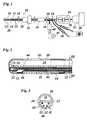
- FIG. 1is a schematic view of an epidural catheter having two contacts, a thermocouple, and a hose line;
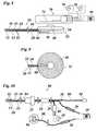
- FIG. 2is a schematic longitudinal sectional view of a tip of a first embodiment of an epidural catheter
- FIG. 3is a transverse sectional view of the catheter of FIG. 2 ;
- FIGS. 4 and 5show a second embodiment of a catheter in views corresponding to FIGS. 2 and 3 ;
- FIGS. 6 and 7show a third embodiment of a catheter in views corresponding to FIGS. 2 and 3 ;
- FIG. 8is a schematic view of an embodiment of an epidural catheter having a transducer with a coil within a flat casing being subcutaneously implantable, as well as an external device having an antenna;
- FIG. 9is another view of the casing and the transducer with the coil
- FIG. 10is a schematic view of a stimulation lead passing through an endoscopic probe; the lead having one electrical contact and a thermocouple;
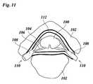
- FIG. 11is a cross-sectional anatomical view of a spinal cord in a spinal column.
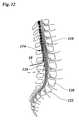
- FIG. 12is a sectional view of a spine taken along the length of the spine
- FIG. 1shows an epidural catheter 10 comprising in its distal region a distal contact 12 and a proximal contact 14 between which a lateral aperture 16 of a hose line 18 is disposed.
- Contacts 12 and 14are drawn with hatching.
- the distal contact 12forms a cap encasing the end of the catheter 10 .
- the proximal contact 14forms an annular strip encircling the catheter 10 .
- the edges of the contacts 12 and 14are flush with a mantle 20 of the catheter 10 made of silicone rubber.
- the outer diameter of the mantle 20is 1.33 mm, corresponding to a specification of 4 French.
- the contacts 12 and 14extend to a length approximately corresponding to the outer diameter of the mantle 20 .
- the contacts 12 and 14are offset to each other by approximately 4 mm in longitudinal direction of the catheter 10 .
- the overall length of the shown epidural catheter 10is 60 cm, however, other lengths are also conceivable.
- thermocouple 21( FIG. 2 ) is thermally connected to the distal contact 12 .
- Electrical leads 22 for the electrical contacts 12 , 14 as well as connecting wires 23 and 24 of the thermocouple 21run within the mantle 20 parallel to hose line 18 and are, like hose line 18 , indicated with dashed lines in FIG. 1 .
- Thermocouple 21is of the type nickel-chromium/nickel, wire 23 being of nickel-chromium and wire 24 being of nickel.
- the internal configuration of catheter 10will be further explained below with FIGS. 2 and 3 .
- Catheter 10comprises a fixation device 25 which can serve to fasten the catheter to a point where the catheter enters a body, the element 25 being configured like in a conventional implantable catheter. Furthermore, in a known manner an aseptic guide wire (not shown) is disposed within the hose line that serves to push the catheter 10 to the desired position in the spinal canal and is then retreated. The guide wire is slightly bendable in the region of its leading end.
- the electrical leads 22are led out of the mantle 20 of catheter 10 in form of electrically isolated wires 28 , and wires 23 and 24 are led out of the mantle 20 into an isolated cord 29 .
- the hose line 18continues within a mantle 30 , which is a continuation of mantle 20 , to a connector 32 .
- Said connectorserves for connecting a syringe or a drug pump and is configured in a conventional manner.
- a clip 34that allows to clamp hose line 18 and re-open it by releasing clip 34 .
- the clip 34is configured in a conventional manner, as well, and can also be disposed at the connection 32 .
- Wires 28are provided with electrical connectors 36 and 38 .
- Connector 36is connected to the distal contact 12
- a connector 38is connected to the proximal contact 14 of the catheter.
- Connectors 36 and 38are merely schematically shown in the drawing, and can be encoded in terms of color and/or in terms of the shape of contacts of the connectors.
- Said connectorsare adapted to be directly or via an adapter (not shown) connected to a pulse generator 39 generating a pulsed high frequency current.
- the pulse generator 39can, for example, be the device N50 of the company Stryker Howmedica, the device RFG-3C+ of the company Radionics, or the device Neurotherm of the company RDG Medical.
- the connectors 36 , 38 , wires 28 , leads 22 , and the contacts 12 and 14are adapted both for application of pulses for a test stimulation of nerves or of a spinal cord having, for example, a voltage in the range of 0 to 12 V, a frequency in the range of 50 to 150 Hz, and a pulse width in the range of 150 to 400 microseconds, as well as for applying pulsed high frequency, for example, within a voltage ranging from 20 to 30 V and a pulsed frequency of 500 kHz and a pulse width of 20 ms.
- the numerical values givenare only examples to illustrate the range of application of the catheter.
- a bipolar connector 40 of cord 29being secured against connecting with the wrong polarity, is connected to the wires 23 and 24 of the thermocouple 21 .
- Connector 40is adapted for connecting to a measuring device 41 , which measures the temperature in the region of the distal contact 12 of the catheter using the thermocouple 21 .
- the measuring device 41can be integrated into the pulse generator 39 in form of an appropriate circuit, for example, or can be connected to the pulse generator, so as to automatically effect a switching off or a change of parameters of pulse generation when a specific temperature is reached; said specific temperature being adjustable.
- an adaptive or stepwise control of pulse generationcan be provided that reduces the power and/or frequency of the pulses when an intended upper temperature limit is approached.
- the pulse generationcan be temporarily stopped until a sufficiently low temperature is reached again.
- FIG. 2shows the tip of the catheter 10 of FIG. 1 as a longitudinal sectional view, though the catheter 10 as well as the leads 22 and wires 23 , 24 disposed in front of and behind the plane of the drawing are shown in a sectional view.
- the electrical leads 22 and wires 23 , 24each comprise an isolation 42 .
- Leads 22are internally soldered to the distal contact 12 and the proximal contact 14 respectively.
- the thermocouple 21is formed by a contact point of the nickel-chromium wire 23 and the nickel wire 24 and is connected to the contact 12 via the wire 23 in immediate proximity. Thus, a good heat conduction between the contact 12 and the thermocouple 21 is accomplished.
- the mantle 20 of the catheter 10comprises an internal partition wall 44 dividing the inside of the catheter 10 into a first hollow space forming the hose line 18 and a second hollow space 46 .
- the leads 22 and wires 23 , 24run within this second hollow space 46 .
- the electrical contacts 12 and 14are separated from the hose line 18 by the mantle 20 .
- the lateral aperture 16 of the mantle 20opens the hose line 18 to the outside.
- FIG. 3shows a cross-sectional view of the catheter 10 along the line III-III of FIG. 2 .
- the arrangement of leads 22 and wires 23 , 24 within the second hollow space 46 of the mantle 20is shown.
- FIGS. 4 and 5show a second embodiment, wherein the mantle 20 has no internal partition wall 44 forming a second hollow space 46 . Instead the electrical leads 22 and the wires 23 , 24 with their respective isolations 42 run within a thickened area of the wall of the mantle 20 of the catheter 10 .
- the hose line 18is formed inside the mantle 20 in a way similar to the first embodiment.
- FIGS. 6 and 7show a third embodiment which differs from the second embodiment in that inside the mantle 20 , there is an additional internal tubular layer 48 forming the hose line 18 .
- the mantle 20encloses the tube formed by the internal layer 48 as well as the isolations 42 of the electrical leads 22 and wires 23 , 24 .
- the internal layer 48is tightly connected to the mantle 20 .
- the internal layer 48can also be a part of a mantle of the catheter constituted of two or more layers.
- the tube formed by the inner layer 48ends on the other side of the aperture 16 . It can, however, also extend into the cap formed by the distal contact 12 as indicated by chain dotted lines.
- the internal layer 48is isolated by the mantle 20 from the contacts 12 and 14 .
- the catheter of the inventioncan also have a configuration that differs from these embodiments, for example a combination of the inner layer 48 of FIG. 7 with the two hollow spaces of the mantle 20 of FIG. 3 , or a different location of the thermocouple 21 .
- the electrical contact 12can also be configured having the shape of an annular strip. It goes without saying that more than the two shown contacts can be provided.
- FIGS. 8 and 9show another embodiment of the catheter 10 the distal part of which is constituted similar to the catheter of the third embodiment shown in FIGS. 6 and 7 .
- the catheterAs the proximal end of the catheter 10 , the catheter is seamlessly connected to a flat casing 52 .
- the upper region of the casing 52contains an injection chamber 54 which is connected to the hose line 18 .
- the upper wall of the injection chamber 24comprises a bulge forming a port 56 in form of an injection septum.
- the injection chamber of the implanted catheteris accessible from external by way of an injection needle, for example.
- the injection septumis made in a known manner such that its wall is sufficiently dense and elastic so as to provide a reliable sealing after an injection needle previously inserted through the septum is retracted.
- the coil 58is arranged spirally, as can be seen more clearly in FIG. 9 .
- the coil 58is a sending and receiving coil and is connected to a transducer 60 .
- the transducer 60has several functions which will be explained hereinafter.
- an aperture for introducing the guide wireis closed before implanting the casing.
- the electrical leads 22 and the wires 23 , 24are connected to the transducer 60 .
- the transduceris adapted to measure currents and/or voltages.
- the transducer 60can measure a thermovoltage on the wires 23 and 24 of the thermocouple, thereby monitoring the temperature at the distal end of the catheter 10 .
- the transducer 60can also measure potentials between the electrical contacts 12 and 14 , for example. Such potentials can provide information about the excitation condition of nerve roots or the spinal cord, for example.
- the transducer 60is addressed by an external device 70 comprising an antenna 72 cooperating with the sending and receiving coil 58 of the transducer 60 .
- the pulse generator 39 and indication devices 76are connectable to the external device 70 .
- the pulse generator 39produces a pulsed high frequency current.
- the high frequency pulsesare inductively transmitted by the antenna 72 to the coil 58 and are relayed by the transducer 60 to the leads 22 of the electrical contacts 12 and 14 .
- the contacts 12 and 14 , the leads 22 , and the transducer 60 and the coil 58are adapted both for application of pulses for a test stimulation of nerves or of a spinal cord having, for example, a voltage in the range of 0 to 12 V, a frequency in the range of 50 to 150 Hz, and a pulse width in the range of 150 to 400 microseconds, as well as for applying pulsed high frequency, for example, within a voltage ranging from 20 to 30 V and a pulsed frequency of 500 kHz and a pulse width of 20 ms.
- the numerical values givenare only examples to illustrate the range of application of the catheter.
- the transducer 60can send signals via the coil 58 to the external device 70 , which receives the signals by means of its antenna 72 .
- Informationcan be transmitted concerning the temperature measured by the temperature sensor as well as information concerning electrical signals the transducer 60 receives from the electrical contacts 12 and 14 .
- further signalscan be transmitted from the transducer 60 to the external device 70 or in the opposite direction for control purposes, for example.
- the indication devices 76can display measured voltages, currents or temperatures.
- the transducer 60can effect an automatic switching off or changing of parameters of pulse generation of the pulse generator 39 by means of control signals, for example.
- an adaptive or stepwise control of pulse generationcan be provided that reduces the power and/or frequency of the pulses when an intended upper temperature limit is approached.
- the pulse generationcan be temporarily stopped until a sufficiently low temperature is reached again.
- FIG. 9shows the casing 52 of the catheter 10 of FIG. 8 as viewed from the bottom of FIG. 8 .
- the spiral configuration of the coil 58is visible.
- FIG. 10shows an endoscopic probe 80 with a light conductor 82 that contains optical fibers for light delivery and visualization, as is known in the art.
- the endoscopic probe 80also comprises a stimulation lead 84 having a distal electrical contact 12 in the distal region of the probe 80 .
- the light conductor 82ends at the distal end of the probe 80 .
- the endoscopic probe 80 and the stimulation lead 84are configured similar to the catheter 10 of FIG. 1 , the major difference being that the hose line 18 is replaced by the light conductor 82 . Therefore, similar parts are numbered with the same numbers as in FIG. 1 , and the respective parts of the description of the catheter of FIG. 1 are included herein by reference.
- Another difference to the catheter 10 of FIG. 1is that the stimulation lead 84 has only one contact 12 in its distal region. This contact 12 is connected to the connector 36 .
- a second, external contact 86is connected via a wire 88 to the connector 38 .
- Contact 12forms an annular strip encircling the probe 80 .
- a thermocoupleis thermally connected to the contact 12 .
- the light conductor 82continues within a light cable 90 that is compatible to standard light cables for endoscopy and ends at a connector 92 .
- FIG. 11shows a sectional view of a spinal cord 100 and a spinal column at a level of a vertebra 102 .
- Dorsal roots 104 and ventral roots 106 as well as spinal ganglia 108 of spinal nerves 110are indicated.
- an epidural space 112is shown into which the catheter 10 is to be inserted.
- FIG. 12schematically shows insertion of the partially shown catheter 10 into the spine.
- the catheter 10can be placed at the medullary conus 114 and cauda equina 116 .
- the 12th thoracic vertebra 118 , the 5th lumbar vertebra 120 and the 1st sacral vertebra 122are indicated.
- the catheter 10can be inserted in a similar manner as conventional spinal cord stimulation (SCS) electrodes.
- a guide wire(mandrel) is used to steer the catheter in place and can be bent. The procedure is as easy as the placement of an SCS.
- the catheteris, for example, inserted at the contralateral or ipsilateral side into the mid-line of epidural space 112 or laterally and pushed obliquely upwards, passing the dorsal roots 104 of the spinal nerves 110 .
- the catheter 10is usually inserted under local or general anesthesia percutaneously through a Tuhoy needle by the loss of resistance technique into the epidural space 112 .
- the catheter 10is then pushed forward in an oblique way to lie at the dorso-lateral wall of the spinal canal.
- the point of insertiondepends on the nerves intended to treat. If, for example, it is intended to treat the lumbar nerves the catheter is introduced at the L 2 / 3 space, as indicated in FIG. 12 , pushing it up to the Th. 12 level, thus enabling to stimulate the nerves Th 12 up to L 5 . Or if it is intended to stimulate the sacral nerves the catheter has to be inserted at a deeper level L 3 / 4 , as indicated with a dashed line, pushing it up to the level L 1 . Then it is possible to treat the entire lumbar roots in addition to all sacral roots.
- the response of the patientis an accurate indication for the distances of the tip to the desired nerve.
- the catheter 10After inserting and pushing upwards the catheter 10 , at first the most cranial nerve root is stimulated and there, the PRF application is performed. Then, while stimulating, the catheter 10 is slowly retrieved. The sensations diminish and then when reaching the next nerve root rise again. There, the next PRF application is started. This procedure is repeated until all nerve roots positioned in the course of the catheter have been treated.
- the temperature sensor at the tipallows to be continuously informed about the temperatures at the tip.
- the catheter 10can be left in place up to 30 days. The procedures can be repeated at the same or any other level. It is also possible to add the catheter to an implantable device to repeat the PRF application at any time, as described herein before.
- the catheter 10is cannulated and allows to inject fluids, like steroids and other substances used in adhesiolysis, if desired. Medicaments can be injected as in any other catheter. Thus, it is possible to stimulate the dorsal nerve roots and ganglia proximal to the spinal ganglia and to apply PRF.
- this flexible catheteris easier and safer to use.
- the distal contactapplies PRF and stimulation with all possible frequencies. This enables a very accurate positioning of the tip.
- Adapterscan be provided for to connect the catheter to any radio frequency generator.
- nerve conductioncan be measured.
- the catheterallows direct application of pulsed radio frequency to neural structures in the skull, the epidural space and in the spinal canal. This was until today impossible. It largely extends the use of radio frequency which was limited by using thermo-lesion needles outside of the epidural space, the spinal cord or canal. It is safer than heat and can be applied directly to the spinal cord. A permanent temperature control at the top of the catheter makes the procedure safe.
- Adhesiolysis and the injection of steroidsare possible. Exact placement by stimulation is another benefit of the catheter.
- the new oblique application techniquecould be of great therapeutic value.
Landscapes
- Health & Medical Sciences (AREA)
- Life Sciences & Earth Sciences (AREA)
- General Health & Medical Sciences (AREA)
- Animal Behavior & Ethology (AREA)
- Veterinary Medicine (AREA)
- Public Health (AREA)
- Engineering & Computer Science (AREA)
- Biomedical Technology (AREA)
- Nuclear Medicine, Radiotherapy & Molecular Imaging (AREA)
- Radiology & Medical Imaging (AREA)
- Neurosurgery (AREA)
- Neurology (AREA)
- Heart & Thoracic Surgery (AREA)
- Cardiology (AREA)
- Orthopedic Medicine & Surgery (AREA)
- Psychology (AREA)
- Biophysics (AREA)
- Physiology (AREA)
- Media Introduction/Drainage Providing Device (AREA)
Abstract
Description
- inserting a flexible epidural catheter into said region, said catheter having at least two electrical contacts in a distal region of the catheter;
- operating a pulsed radio frequency generator; the pulsed radio frequency generator being coupled to the electrical contacts; thereby applying pulsed radio frequency energy via said electrical contacts to at least one of the spinal cord or spinal nerves;
- inserting a flexible catheter percutaneously into said space, the catheter having at least one electrical contact at its distal region;
- then pushing the catheter forward, thereby positioning said at least one contact in the spinal canal;
- adjusting the catheter such that said at least one electrical contact is in a region of the at least one of a nerve, a nerve root, a nerve ganglion, and a part of the spinal cord; and
- operating a pulsed radio frequency generator, thereby applying pulsed radio frequency energy via the at least one electrical contact to the region of the at least one of a nerve, a nerve root, a nerve ganglion, and a part of a spinal cord. Thereby, the at least one of a nerve, a nerve root, a nerve ganglion, and a part of a spinal cord is treated.
- monitoring a temperature using the temperature sensor at the distal region of the lead;
- wherein in the step of operating the pulsed radio frequency generator, the pulsed radio frequency energy is applied depending in a predetermined way on the monitored temperature.
- displacing the lead to a second localized region; and then
- repeating the step of operating the pulsed radio frequency generator;
- whereby in said second localized region at least one of a nerve, a nerve root, a nerve ganglion, a part of the spinal cord and a part of the brain is treated.
Claims (10)
Priority Applications (3)
| Application Number | Priority Date | Filing Date | Title |
|---|---|---|---|
| US11/049,247US9168368B2 (en) | 2003-04-08 | 2005-02-02 | Method for applying pulsed radio frequency energy to the spinal canal |
| US14/865,183US9950185B2 (en) | 2003-04-08 | 2015-09-25 | Method for applying pulsed radio frequency energy to the spinal canal |
| US15/916,372US10322292B2 (en) | 2003-04-08 | 2018-03-09 | Method for applying pulsed radio frequency energy to the spinal canal |
Applications Claiming Priority (9)
| Application Number | Priority Date | Filing Date | Title |
|---|---|---|---|
| DE2003212110DE20312110U1 (en) | 2003-04-08 | 2003-04-08 | Flexible epidural catheter for treating nerves system, has internally arranged leads of respective electrical contacts, connected with high frequency pulse generator for nerve stimulation |
| DE20308422UDE20308422U1 (en) | 2003-05-27 | 2003-05-27 | Flexible epidural catheter for treating nerves system, has internally arranged leads of respective electrical contacts, connected with high frequency pulse generator for nerve stimulation |
| DE20308422U | 2003-05-27 | ||
| DE20308422.5 | 2003-05-27 | ||
| DE20312110U | 2003-08-04 | ||
| DE20312110.4 | 2003-08-04 | ||
| DE202004000852U | 2004-01-20 | ||
| DE202004000852.1 | 2004-01-20 | ||
| DE202004000852UDE202004000852U1 (en) | 2004-01-20 | 2004-01-20 | catheter |
Related Child Applications (1)
| Application Number | Title | Priority Date | Filing Date |
|---|---|---|---|
| US11/049,247Continuation-In-PartUS9168368B2 (en) | 2003-04-08 | 2005-02-02 | Method for applying pulsed radio frequency energy to the spinal canal |
Publications (2)
| Publication Number | Publication Date |
|---|---|
| US20040210290A1 US20040210290A1 (en) | 2004-10-21 |
| US9446229B2true US9446229B2 (en) | 2016-09-20 |
Family
ID=33162606
Family Applications (4)
| Application Number | Title | Priority Date | Filing Date |
|---|---|---|---|
| US10/844,639Expired - Fee RelatedUS9446229B2 (en) | 2003-04-08 | 2004-05-13 | Catheter |
| US11/049,247Expired - Fee RelatedUS9168368B2 (en) | 2003-04-08 | 2005-02-02 | Method for applying pulsed radio frequency energy to the spinal canal |
| US14/865,183Expired - LifetimeUS9950185B2 (en) | 2003-04-08 | 2015-09-25 | Method for applying pulsed radio frequency energy to the spinal canal |
| US15/916,372Expired - Fee RelatedUS10322292B2 (en) | 2003-04-08 | 2018-03-09 | Method for applying pulsed radio frequency energy to the spinal canal |
Family Applications After (3)
| Application Number | Title | Priority Date | Filing Date |
|---|---|---|---|
| US11/049,247Expired - Fee RelatedUS9168368B2 (en) | 2003-04-08 | 2005-02-02 | Method for applying pulsed radio frequency energy to the spinal canal |
| US14/865,183Expired - LifetimeUS9950185B2 (en) | 2003-04-08 | 2015-09-25 | Method for applying pulsed radio frequency energy to the spinal canal |
| US15/916,372Expired - Fee RelatedUS10322292B2 (en) | 2003-04-08 | 2018-03-09 | Method for applying pulsed radio frequency energy to the spinal canal |
Country Status (1)
| Country | Link |
|---|---|
| US (4) | US9446229B2 (en) |
Cited By (15)
| Publication number | Priority date | Publication date | Assignee | Title |
|---|---|---|---|---|
| US9724151B2 (en) | 2013-08-08 | 2017-08-08 | Relievant Medsystems, Inc. | Modulating nerves within bone using bone fasteners |
| US9775627B2 (en) | 2012-11-05 | 2017-10-03 | Relievant Medsystems, Inc. | Systems and methods for creating curved paths through bone and modulating nerves within the bone |
| US10028753B2 (en) | 2008-09-26 | 2018-07-24 | Relievant Medsystems, Inc. | Spine treatment kits |
| US10111704B2 (en) | 2002-09-30 | 2018-10-30 | Relievant Medsystems, Inc. | Intraosseous nerve treatment |
| US10265099B2 (en) | 2008-09-26 | 2019-04-23 | Relievant Medsystems, Inc. | Systems for accessing nerves within bone |
| US10390877B2 (en) | 2011-12-30 | 2019-08-27 | Relievant Medsystems, Inc. | Systems and methods for treating back pain |
| US10463423B2 (en) | 2003-03-28 | 2019-11-05 | Relievant Medsystems, Inc. | Thermal denervation devices and methods |
| US10588691B2 (en) | 2012-09-12 | 2020-03-17 | Relievant Medsystems, Inc. | Radiofrequency ablation of tissue within a vertebral body |
| USRE48460E1 (en) | 2002-09-30 | 2021-03-09 | Relievant Medsystems, Inc. | Method of treating an intraosseous nerve |
| US11007010B2 (en) | 2019-09-12 | 2021-05-18 | Relevant Medsysterns, Inc. | Curved bone access systems |
| US11717342B2 (en) | 2019-04-11 | 2023-08-08 | Gyrus Acmi, Inc. | Medical device |
| US11766288B2 (en) | 2019-02-22 | 2023-09-26 | Gyrus Acmi, Inc. | Flexible bipolar sheath |
| US12039731B2 (en) | 2020-12-22 | 2024-07-16 | Relievant Medsystems, Inc. | Prediction of candidates for spinal neuromodulation |
| US12082876B1 (en) | 2020-09-28 | 2024-09-10 | Relievant Medsystems, Inc. | Introducer drill |
| US12433668B1 (en) | 2021-11-08 | 2025-10-07 | Relievant Medsystems, Inc. | Impedance stoppage mitigation during radiofrequency tissue ablation procedures |
Families Citing this family (56)
| Publication number | Priority date | Publication date | Assignee | Title |
|---|---|---|---|---|
| US7837719B2 (en) | 2002-05-09 | 2010-11-23 | Daemen College | Electrical stimulation unit and waterbath system |
| DE202004000852U1 (en)* | 2004-01-20 | 2005-06-02 | Omar-Pasha, Omar | catheter |
| US9446229B2 (en)* | 2003-04-08 | 2016-09-20 | Omar Omar-Pasha | Catheter |
| US20120277839A1 (en) | 2004-09-08 | 2012-11-01 | Kramer Jeffery M | Selective stimulation to modulate the sympathetic nervous system |
| US7337005B2 (en)* | 2004-09-08 | 2008-02-26 | Spinal Modulations, Inc. | Methods for stimulating a nerve root ganglion |
| US9205261B2 (en) | 2004-09-08 | 2015-12-08 | The Board Of Trustees Of The Leland Stanford Junior University | Neurostimulation methods and systems |
| DE202005000544U1 (en)* | 2005-01-13 | 2006-05-24 | Mantsch, Christian | Medical electrode system |
| US8075556B2 (en)* | 2006-05-23 | 2011-12-13 | Andres Betts | High frequency epidural neuromodulation catheter for effectuating RF treatment in spinal canal and method of using same |
| US8103356B2 (en)* | 2006-05-23 | 2012-01-24 | Vertech, Inc. | High frequency epidural neuromodulation catheter without needle for effectuating RF treatment |
| EP1880662A1 (en)* | 2006-07-19 | 2008-01-23 | Bioampere Research S.r.l. | Videoguide for medical use in diagnostics and mini-invasive therapeutic treatment |
| US9314618B2 (en) | 2006-12-06 | 2016-04-19 | Spinal Modulation, Inc. | Implantable flexible circuit leads and methods of use |
| CA2671250A1 (en) | 2006-12-06 | 2008-06-12 | Spinal Modulation, Inc. | Hard tissue anchors and delivery devices |
| WO2008070808A2 (en) | 2006-12-06 | 2008-06-12 | Spinal Modulation, Inc. | Expandable stimulation leads and methods of use |
| JP5414531B2 (en) | 2006-12-06 | 2014-02-12 | スパイナル・モデュレーション・インコーポレイテッド | Delivery device and systems and methods for stimulating neural tissue at multiple spinal levels |
| EP2091604B1 (en)* | 2006-12-14 | 2012-09-05 | William F. Urmey | Catheter positioning system |
| JP5562648B2 (en) | 2007-01-29 | 2014-07-30 | スパイナル・モデュレーション・インコーポレイテッド | Non-stitched top retaining mechanism |
| US8353943B2 (en)* | 2008-08-29 | 2013-01-15 | Cook Medical Technologies Llc | Variable weave graft with metal strand reinforcement for in situ fenestration |
| EP2373378B1 (en) | 2008-10-27 | 2017-04-26 | Spinal Modulation Inc. | Selective stimulation systems and signal parameters for medical conditions |
| US8380318B2 (en) | 2009-03-24 | 2013-02-19 | Spinal Modulation, Inc. | Pain management with stimulation subthreshold to paresthesia |
| WO2010132816A2 (en) | 2009-05-15 | 2010-11-18 | Spinal Modulation, Inc. | Methods, systems and devices for neuromodulating spinal anatomy |
| CA2798961A1 (en) | 2010-05-10 | 2011-11-17 | Spinal Modulation, Inc. | Methods, systems and devices for reducing migration |
| CA2746948C (en) | 2010-07-21 | 2019-01-15 | Diros Technology Inc. | Advanced multi-purpose catheter probes for diagnostic and therapeutic procedures |
| US8805519B2 (en) | 2010-09-30 | 2014-08-12 | Nevro Corporation | Systems and methods for detecting intrathecal penetration |
| US8965482B2 (en) | 2010-09-30 | 2015-02-24 | Nevro Corporation | Systems and methods for positioning implanted devices in a patient |
| CN103561811A (en) | 2011-02-02 | 2014-02-05 | 脊髓调制公司 | Devices, systems and methods for the targeted treatment of movement disorders |
| US20170050017A1 (en)* | 2013-02-25 | 2017-02-23 | Cosman Medical, Inc. | Electrosurgical System |
| US10076384B2 (en) | 2013-03-08 | 2018-09-18 | Symple Surgical, Inc. | Balloon catheter apparatus with microwave emitter |
| CA2903843C (en) | 2013-03-15 | 2019-03-05 | Alfred E. Mann Foundation For Scientific Research | Current sensing multiple output current stimulators with fast turn on time |
| US9780596B2 (en) | 2013-07-29 | 2017-10-03 | Alfred E. Mann Foundation For Scientific Research | Microprocessor controlled class E driver |
| WO2015179177A1 (en) | 2014-05-20 | 2015-11-26 | Nevro Corporation | Implanted pulse generators with reduced power consumption via signal strength/duration characteristics, and associated systems and methods |
| CA2958210C (en) | 2014-08-15 | 2023-09-26 | Axonics Modulation Technologies, Inc. | Integrated electromyographic clinician programmer for use with an implantable neurostimulator |
| AU2015301401B2 (en) | 2014-08-15 | 2020-01-16 | Axonics Modulation Technologies, Inc. | Electromyographic lead positioning and stimulation titration in a nerve stimulation system for treatment of overactive bladder |
| ES2782556T3 (en) | 2014-08-15 | 2020-09-15 | Axonics Modulation Tech Inc | System for neurostimulation electrode configurations based on neuronal location |
| AU2015301398B2 (en) | 2014-08-15 | 2020-05-21 | Axonics Modulation Technologies, Inc. | Implantable lead affixation structure for nerve stimulation to alleviate bladder dysfunction and other indications |
| CA3208375A1 (en) | 2014-08-15 | 2016-02-18 | Axonics, Inc. | External pulse generator device and associated methods for trial nerve stimulation |
| KR101653888B1 (en)* | 2014-12-31 | 2016-09-02 | 영남대학교 산학협력단 | Passive type trans-sacral implanted epidural pulsed radio frequency stimulator for spinal cord stimulation |
| KR101653889B1 (en)* | 2014-12-31 | 2016-09-09 | 영남대학교 산학협력단 | Active type trans-sacral implanted epidural pulsed radio frequency stimulator for spinal cord stimulation |
| CA2973192C (en) | 2015-01-09 | 2023-04-04 | Axonics Modulation Technologies, Inc. | Improved antenna and methods of use for an implantable nerve stimulator |
| JP6751718B2 (en) | 2015-01-09 | 2020-09-09 | アクソニクス モジュレーション テクノロジーズ インコーポレイテッド | Mounting devices and related methods for use with neurostimulation charging devices |
| CN107427675B (en) | 2015-01-09 | 2021-10-26 | 艾克索尼克斯股份有限公司 | Patient remote control and associated method for use with a neurostimulation system |
| AU2016291554B2 (en) | 2015-07-10 | 2021-01-07 | Axonics Modulation Technologies, Inc. | Implantable nerve stimulator having internal electronics without ASIC and methods of use |
| US10300277B1 (en) | 2015-12-14 | 2019-05-28 | Nevro Corp. | Variable amplitude signals for neurological therapy, and associated systems and methods |
| JP6876363B2 (en) | 2016-01-29 | 2021-05-26 | アクソニクス モジュレーション テクノロジーズ インコーポレイテッド | Methods and systems for frequency adjustment that optimize the charging of implantable neurostimulators |
| WO2017139784A1 (en) | 2016-02-12 | 2017-08-17 | Axonics Modulation Technologies, Inc. | External pulse generator device and associated methods for trial nerve stimulation |
| US10980999B2 (en) | 2017-03-09 | 2021-04-20 | Nevro Corp. | Paddle leads and delivery tools, and associated systems and methods |
| WO2019152553A1 (en) | 2018-01-30 | 2019-08-08 | Jon Parker | Efficient use of an implantable pulse generator battery, and associated systems and methods |
| WO2019165108A1 (en) | 2018-02-22 | 2019-08-29 | Axonics Modulation Technologies, Inc. | Neurostimulation leads for trial nerve stimulation and methods of use |
| WO2019191423A1 (en) | 2018-03-29 | 2019-10-03 | Nevro Corp. | Leads having sidewall openings, and associated systems and methods |
| DE102018120761A1 (en)* | 2018-08-24 | 2020-02-27 | Biotronik Se & Co. Kg | Electrode lead with integrated deformation sensor |
| US11058875B1 (en) | 2018-09-19 | 2021-07-13 | Nevro Corp. | Motor function in spinal cord injury patients via electrical stimulation, and associated systems and methods |
| US11590352B2 (en) | 2019-01-29 | 2023-02-28 | Nevro Corp. | Ramped therapeutic signals for modulating inhibitory interneurons, and associated systems and methods |
| US11642537B2 (en) | 2019-03-11 | 2023-05-09 | Axonics, Inc. | Charging device with off-center coil |
| AU2020244792A1 (en)* | 2019-03-25 | 2021-11-11 | Ennovation, Llc | Neuromodulation catheter |
| US11439829B2 (en) | 2019-05-24 | 2022-09-13 | Axonics, Inc. | Clinician programmer methods and systems for maintaining target operating temperatures |
| WO2020242900A1 (en) | 2019-05-24 | 2020-12-03 | Axonics Modulation Technologies, Inc. | Trainer device for a neurostimulator programmer and associated methods of use with a neurostimulation system |
| US12420103B1 (en) | 2020-08-20 | 2025-09-23 | Axonics, Inc. | Neurostimulation leads with reduced current leakage |
Citations (19)
| Publication number | Priority date | Publication date | Assignee | Title |
|---|---|---|---|---|
| US4379462A (en) | 1980-10-29 | 1983-04-12 | Neuromed, Inc. | Multi-electrode catheter assembly for spinal cord stimulation |
| US4607639A (en) | 1984-05-18 | 1986-08-26 | Regents Of The University Of California | Method and system for controlling bladder evacuation |
| DE3602219A1 (en) | 1986-01-25 | 1987-07-30 | Vygon Erzeugnisse | Neuroelectrode |
| US4762517A (en)* | 1986-09-18 | 1988-08-09 | Healthcare Technologies, Inc. | Subcutaneously-implanted drug delivery system for intravenous injections, and the like |
| US5081990A (en) | 1990-05-11 | 1992-01-21 | New York University | Catheter for spinal epidural injection of drugs and measurement of evoked potentials |
| WO1992007605A1 (en) | 1990-11-05 | 1992-05-14 | Ravi Xavier | Implantable drug dispensing multielectrode catheter |
| US5374285A (en) | 1992-07-31 | 1994-12-20 | Aries S.R.L. | Spinal electrode catheter |
| EP0644736A1 (en) | 1992-04-08 | 1995-03-29 | Danek Medical, Inc. | Endoscope for direct visualization of the spine and epidural space |
| US5423877A (en) | 1992-05-04 | 1995-06-13 | David C. Mackey | Method and device for acute pain management by simultaneous spinal cord electrical stimulation and drug infusion |
| US5713923A (en) | 1996-05-13 | 1998-02-03 | Medtronic, Inc. | Techniques for treating epilepsy by brain stimulation and drug infusion |
| US6208881B1 (en)* | 1998-10-20 | 2001-03-27 | Micropure Medical, Inc. | Catheter with thin film electrodes and method for making same |
| US6227203B1 (en)* | 1998-02-12 | 2001-05-08 | Medtronic, Inc. | Techniques for controlling abnormal involuntary movements by brain stimulation and drug infusion |
| US6246912B1 (en)* | 1996-06-27 | 2001-06-12 | Sherwood Services Ag | Modulated high frequency tissue modification |
| US20010023348A1 (en) | 1996-10-23 | 2001-09-20 | Ashley John E. | Catheter for delivery of energy to a surgical site |
| EP1145731A2 (en) | 2000-04-12 | 2001-10-17 | Regents Of The University Of Minnesota | Multi-probe system |
| US6322549B1 (en) | 1998-02-20 | 2001-11-27 | Arthocare Corporation | Systems and methods for electrosurgical treatment of tissue in the brain and spinal cord |
| EP1181947A2 (en) | 2000-08-17 | 2002-02-27 | William N. Borkan | Spinal cord stimulation leads |
| US20030004549A1 (en)* | 2000-10-26 | 2003-01-02 | Medtronic, Inc. | Method and apparatus to minimize the effects of a cardiac insult |
| US6770070B1 (en)* | 2000-03-17 | 2004-08-03 | Rita Medical Systems, Inc. | Lung treatment apparatus and method |
Family Cites Families (6)
| Publication number | Priority date | Publication date | Assignee | Title |
|---|---|---|---|---|
| US4044774A (en) | 1976-02-23 | 1977-08-30 | Medtronic, Inc. | Percutaneously inserted spinal cord stimulation lead |
| US4468628A (en) | 1983-01-17 | 1984-08-28 | Tektronix, Inc. | Differential amplifier with high common-mode rejection |
| US4907589A (en)* | 1988-04-29 | 1990-03-13 | Cosman Eric R | Automatic over-temperature control apparatus for a therapeutic heating device |
| US6146380A (en) | 1998-01-09 | 2000-11-14 | Radionics, Inc. | Bent tip electrical surgical probe |
| US7167756B1 (en) | 2000-04-28 | 2007-01-23 | Medtronic, Inc. | Battery recharge management for an implantable medical device |
| US9446229B2 (en)* | 2003-04-08 | 2016-09-20 | Omar Omar-Pasha | Catheter |
- 2004
- 2004-05-13USUS10/844,639patent/US9446229B2/ennot_activeExpired - Fee Related
- 2005
- 2005-02-02USUS11/049,247patent/US9168368B2/ennot_activeExpired - Fee Related
- 2015
- 2015-09-25USUS14/865,183patent/US9950185B2/ennot_activeExpired - Lifetime
- 2018
- 2018-03-09USUS15/916,372patent/US10322292B2/ennot_activeExpired - Fee Related
Patent Citations (19)
| Publication number | Priority date | Publication date | Assignee | Title |
|---|---|---|---|---|
| US4379462A (en) | 1980-10-29 | 1983-04-12 | Neuromed, Inc. | Multi-electrode catheter assembly for spinal cord stimulation |
| US4607639A (en) | 1984-05-18 | 1986-08-26 | Regents Of The University Of California | Method and system for controlling bladder evacuation |
| DE3602219A1 (en) | 1986-01-25 | 1987-07-30 | Vygon Erzeugnisse | Neuroelectrode |
| US4762517A (en)* | 1986-09-18 | 1988-08-09 | Healthcare Technologies, Inc. | Subcutaneously-implanted drug delivery system for intravenous injections, and the like |
| US5081990A (en) | 1990-05-11 | 1992-01-21 | New York University | Catheter for spinal epidural injection of drugs and measurement of evoked potentials |
| WO1992007605A1 (en) | 1990-11-05 | 1992-05-14 | Ravi Xavier | Implantable drug dispensing multielectrode catheter |
| EP0644736A1 (en) | 1992-04-08 | 1995-03-29 | Danek Medical, Inc. | Endoscope for direct visualization of the spine and epidural space |
| US5423877A (en) | 1992-05-04 | 1995-06-13 | David C. Mackey | Method and device for acute pain management by simultaneous spinal cord electrical stimulation and drug infusion |
| US5374285A (en) | 1992-07-31 | 1994-12-20 | Aries S.R.L. | Spinal electrode catheter |
| US5713923A (en) | 1996-05-13 | 1998-02-03 | Medtronic, Inc. | Techniques for treating epilepsy by brain stimulation and drug infusion |
| US6246912B1 (en)* | 1996-06-27 | 2001-06-12 | Sherwood Services Ag | Modulated high frequency tissue modification |
| US20010023348A1 (en) | 1996-10-23 | 2001-09-20 | Ashley John E. | Catheter for delivery of energy to a surgical site |
| US6227203B1 (en)* | 1998-02-12 | 2001-05-08 | Medtronic, Inc. | Techniques for controlling abnormal involuntary movements by brain stimulation and drug infusion |
| US6322549B1 (en) | 1998-02-20 | 2001-11-27 | Arthocare Corporation | Systems and methods for electrosurgical treatment of tissue in the brain and spinal cord |
| US6208881B1 (en)* | 1998-10-20 | 2001-03-27 | Micropure Medical, Inc. | Catheter with thin film electrodes and method for making same |
| US6770070B1 (en)* | 2000-03-17 | 2004-08-03 | Rita Medical Systems, Inc. | Lung treatment apparatus and method |
| EP1145731A2 (en) | 2000-04-12 | 2001-10-17 | Regents Of The University Of Minnesota | Multi-probe system |
| EP1181947A2 (en) | 2000-08-17 | 2002-02-27 | William N. Borkan | Spinal cord stimulation leads |
| US20030004549A1 (en)* | 2000-10-26 | 2003-01-02 | Medtronic, Inc. | Method and apparatus to minimize the effects of a cardiac insult |
Cited By (40)
| Publication number | Priority date | Publication date | Assignee | Title |
|---|---|---|---|---|
| US11596468B2 (en) | 2002-09-30 | 2023-03-07 | Relievant Medsystems, Inc. | Intraosseous nerve treatment |
| USRE48460E1 (en) | 2002-09-30 | 2021-03-09 | Relievant Medsystems, Inc. | Method of treating an intraosseous nerve |
| US10111704B2 (en) | 2002-09-30 | 2018-10-30 | Relievant Medsystems, Inc. | Intraosseous nerve treatment |
| US10478246B2 (en) | 2002-09-30 | 2019-11-19 | Relievant Medsystems, Inc. | Ablation of tissue within vertebral body involving internal cooling |
| US10463423B2 (en) | 2003-03-28 | 2019-11-05 | Relievant Medsystems, Inc. | Thermal denervation devices and methods |
| US10265099B2 (en) | 2008-09-26 | 2019-04-23 | Relievant Medsystems, Inc. | Systems for accessing nerves within bone |
| US10905440B2 (en) | 2008-09-26 | 2021-02-02 | Relievant Medsystems, Inc. | Nerve modulation systems |
| US12161350B2 (en) | 2008-09-26 | 2024-12-10 | Relievant Medsystems, Inc. | Systems for treating nerves within bone using steam |
| US12303166B2 (en) | 2008-09-26 | 2025-05-20 | Relievant Medsystems, Inc. | Methods for accessing nerves within bone |
| US11471171B2 (en) | 2008-09-26 | 2022-10-18 | Relievant Medsystems, Inc. | Bipolar radiofrequency ablation systems for treatment within bone |
| US12329412B2 (en) | 2008-09-26 | 2025-06-17 | Relievant Medsystems, Inc. | Systems for accessing nerves within bone |
| US10028753B2 (en) | 2008-09-26 | 2018-07-24 | Relievant Medsystems, Inc. | Spine treatment kits |
| US10390877B2 (en) | 2011-12-30 | 2019-08-27 | Relievant Medsystems, Inc. | Systems and methods for treating back pain |
| US12059193B2 (en) | 2011-12-30 | 2024-08-13 | Relievant Medsystems, Inc. | Methods of denervating vertebral body using external energy source |
| US11471210B2 (en) | 2011-12-30 | 2022-10-18 | Relievant Medsystems, Inc. | Methods of denervating vertebral body using external energy source |
| US10588691B2 (en) | 2012-09-12 | 2020-03-17 | Relievant Medsystems, Inc. | Radiofrequency ablation of tissue within a vertebral body |
| US11737814B2 (en) | 2012-09-12 | 2023-08-29 | Relievant Medsystems, Inc. | Cryotherapy treatment for back pain |
| US11701168B2 (en) | 2012-09-12 | 2023-07-18 | Relievant Medsystems, Inc. | Radiofrequency ablation of tissue within a vertebral body |
| US11690667B2 (en) | 2012-09-12 | 2023-07-04 | Relievant Medsystems, Inc. | Radiofrequency ablation of tissue within a vertebral body |
| US11234764B1 (en) | 2012-11-05 | 2022-02-01 | Relievant Medsystems, Inc. | Systems for navigation and treatment within a vertebral body |
| US11974759B2 (en) | 2012-11-05 | 2024-05-07 | Relievant Medsystems, Inc. | Methods of navigation and treatment within a vertebral body |
| US11291502B2 (en) | 2012-11-05 | 2022-04-05 | Relievant Medsystems, Inc. | Methods of navigation and treatment within a vertebral body |
| US9775627B2 (en) | 2012-11-05 | 2017-10-03 | Relievant Medsystems, Inc. | Systems and methods for creating curved paths through bone and modulating nerves within the bone |
| US10357258B2 (en) | 2012-11-05 | 2019-07-23 | Relievant Medsystems, Inc. | Systems and methods for creating curved paths through bone |
| US10517611B2 (en) | 2012-11-05 | 2019-12-31 | Relievant Medsystems, Inc. | Systems for navigation and treatment within a vertebral body |
| US11160563B2 (en) | 2012-11-05 | 2021-11-02 | Relievant Medsystems, Inc. | Systems for navigation and treatment within a vertebral body |
| US10456187B2 (en) | 2013-08-08 | 2019-10-29 | Relievant Medsystems, Inc. | Modulating nerves within bone using bone fasteners |
| US11065046B2 (en) | 2013-08-08 | 2021-07-20 | Relievant Medsystems, Inc. | Modulating nerves within bone |
| US12193719B2 (en) | 2013-08-08 | 2025-01-14 | Relievant Medsystems, Inc. | Modulating nerves within bone |
| US9724151B2 (en) | 2013-08-08 | 2017-08-08 | Relievant Medsystems, Inc. | Modulating nerves within bone using bone fasteners |
| US11766288B2 (en) | 2019-02-22 | 2023-09-26 | Gyrus Acmi, Inc. | Flexible bipolar sheath |
| US11717342B2 (en) | 2019-04-11 | 2023-08-08 | Gyrus Acmi, Inc. | Medical device |
| US11123103B2 (en) | 2019-09-12 | 2021-09-21 | Relievant Medsystems, Inc. | Introducer systems for bone access |
| US11202655B2 (en) | 2019-09-12 | 2021-12-21 | Relievant Medsystems, Inc. | Accessing and treating tissue within a vertebral body |
| US11007010B2 (en) | 2019-09-12 | 2021-05-18 | Relevant Medsysterns, Inc. | Curved bone access systems |
| US11207100B2 (en) | 2019-09-12 | 2021-12-28 | Relievant Medsystems, Inc. | Methods of detecting and treating back pain |
| US11426199B2 (en) | 2019-09-12 | 2022-08-30 | Relievant Medsystems, Inc. | Methods of treating a vertebral body |
| US12082876B1 (en) | 2020-09-28 | 2024-09-10 | Relievant Medsystems, Inc. | Introducer drill |
| US12039731B2 (en) | 2020-12-22 | 2024-07-16 | Relievant Medsystems, Inc. | Prediction of candidates for spinal neuromodulation |
| US12433668B1 (en) | 2021-11-08 | 2025-10-07 | Relievant Medsystems, Inc. | Impedance stoppage mitigation during radiofrequency tissue ablation procedures |
Also Published As
| Publication number | Publication date |
|---|---|
| US20050137667A1 (en) | 2005-06-23 |
| US9168368B2 (en) | 2015-10-27 |
| US20040210290A1 (en) | 2004-10-21 |
| US20180193656A1 (en) | 2018-07-12 |
| US10322292B2 (en) | 2019-06-18 |
| US20160008618A1 (en) | 2016-01-14 |
| US9950185B2 (en) | 2018-04-24 |
Similar Documents
| Publication | Publication Date | Title |
|---|---|---|
| US9446229B2 (en) | Catheter | |
| US6298256B1 (en) | Device and method for the location and catheterization of the surroundings of a nerve | |
| US20200077916A1 (en) | Method and System for Identification of Source of Chronic Pain and Treatment | |
| JP6035285B2 (en) | Neural stimulation method and system | |
| US20180361144A1 (en) | Apparatus for application of a pulsed radio frequency therapy in a vascular system or another cavity or tissue of the human or animal body | |
| US9402560B2 (en) | Advanced multi-purpose catheter probes for diagnostic and therapeutic procedures | |
| EP1276535B1 (en) | Instrument for delivery of anaesthetic drug | |
| US7949402B2 (en) | Neuro-stimulation and ablation system | |
| US9844644B2 (en) | Intravascular sheath with mapping capabilities to deliver therapeutic devices to a targeted location within a blood vessel | |
| AU2004240655A1 (en) | Instrument and method for delivery of anaesthetic drug | |
| US20090287140A1 (en) | Electrical stimulation and infusion introducer assembly | |
| KR101185944B1 (en) | Catheter set having guide wire | |
| US20210330977A1 (en) | Neuromodulation catheter | |
| CN103096965A (en) | Catheter set comprising guide wire | |
| US9042998B2 (en) | Medical electrode system | |
| RU2033821C1 (en) | Epidural neuroelectrode | |
| US20250025687A1 (en) | Medical lead and method of securing medical electrode leads | |
| ES2341175T3 (en) | MEDICAL SYSTEM OF ELECTRODES. | |
| WO2022010817A1 (en) | A catheter-through-catheter arrangement of stimulating catheters for providing pain control by nerve block and neuromodulation of peripheral nerves | |
| KR20220067642A (en) | Catheter apparatus suitable for treatment of different types of therapy | |
| KR20080093473A (en) | Neural Stimulation Block Set Using Electrode |
Legal Events
| Date | Code | Title | Description |
|---|---|---|---|
| AS | Assignment | Owner name:OMT GMBH, GERMANY Free format text:ASSIGNMENT OF ASSIGNORS INTEREST;ASSIGNOR:PASHA, OMAR OMAR;REEL/FRAME:015185/0843 Effective date:20040708 Owner name:PASHA, OMAR OMAR, GERMANY Free format text:ASSIGNMENT OF ASSIGNORS INTEREST;ASSIGNOR:PASHA, OMAR OMAR;REEL/FRAME:015185/0843 Effective date:20040708 | |
| AS | Assignment | Owner name:OMAR-PASHA, OMAR, GERMANY Free format text:ASSIGNMENT OF ASSIGNORS INTEREST;ASSIGNOR:OMT GMBH;REEL/FRAME:037255/0254 Effective date:20030807 | |
| STCF | Information on status: patent grant | Free format text:PATENTED CASE | |
| MAFP | Maintenance fee payment | Free format text:PAYMENT OF MAINTENANCE FEE, 4TH YR, SMALL ENTITY (ORIGINAL EVENT CODE: M2551); ENTITY STATUS OF PATENT OWNER: SMALL ENTITY Year of fee payment:4 | |
| FEPP | Fee payment procedure | Free format text:MAINTENANCE FEE REMINDER MAILED (ORIGINAL EVENT CODE: REM.); ENTITY STATUS OF PATENT OWNER: SMALL ENTITY | |
| LAPS | Lapse for failure to pay maintenance fees | Free format text:PATENT EXPIRED FOR FAILURE TO PAY MAINTENANCE FEES (ORIGINAL EVENT CODE: EXP.); ENTITY STATUS OF PATENT OWNER: SMALL ENTITY | |
| STCH | Information on status: patent discontinuation | Free format text:PATENT EXPIRED DUE TO NONPAYMENT OF MAINTENANCE FEES UNDER 37 CFR 1.362 | |
| FP | Lapsed due to failure to pay maintenance fee | Effective date:20240920 |