US9445918B1 - Expandable spinal fusion implants and related instruments and methods - Google Patents
Expandable spinal fusion implants and related instruments and methodsDownload PDFInfo
- Publication number
- US9445918B1 US9445918B1US14/060,558US201314060558AUS9445918B1US 9445918 B1US9445918 B1US 9445918B1US 201314060558 AUS201314060558 AUS 201314060558AUS 9445918 B1US9445918 B1US 9445918B1
- Authority
- US
- United States
- Prior art keywords
- spacer
- link
- graft
- view
- aperture
- Prior art date
- Legal status (The legal status is an assumption and is not a legal conclusion. Google has not performed a legal analysis and makes no representation as to the accuracy of the status listed.)
- Active
Links
- 239000007943implantSubstances0.000titleabstractdescription40
- 230000004927fusionEffects0.000titleabstractdescription3
- 238000000034methodMethods0.000titledescription8
- 125000006850spacer groupChemical group0.000claimsabstractdescription130
- 238000003780insertionMethods0.000claimsdescription73
- 230000037431insertionEffects0.000claimsdescription73
- 230000008878couplingEffects0.000claimsdescription15
- 238000010168coupling processMethods0.000claimsdescription15
- 238000005859coupling reactionMethods0.000claimsdescription15
- 210000000988bone and boneAnatomy0.000abstractdescription19
- 239000000316bone substituteSubstances0.000abstractdescription3
- 238000001356surgical procedureMethods0.000abstract1
- 238000002594fluoroscopyMethods0.000description11
- 210000002105tongueAnatomy0.000description11
- 239000000463materialSubstances0.000description7
- 230000007704transitionEffects0.000description7
- 230000013011matingEffects0.000description6
- 238000013459approachMethods0.000description5
- 230000006835compressionEffects0.000description4
- 238000007906compressionMethods0.000description4
- 230000007246mechanismEffects0.000description4
- 230000004913activationEffects0.000description3
- 238000013508migrationMethods0.000description3
- 238000012856packingMethods0.000description3
- 230000000149penetrating effectEffects0.000description3
- 210000004872soft tissueAnatomy0.000description3
- 210000001519tissueAnatomy0.000description3
- 0CCCC[C@]1[C@]2[C@@](C)C[C@]3C4(CCCC4)[C@@](CCCC)CCC[C@@]1C(C1[C@](C4CC4)C4[C@@](CCCC)C(CC)C[C@](C)C[C@@](C)CC#CCCCCC[C@](CC)C4)C1([C@@](*)CC)[C@]2CCC3Chemical compoundCCCC[C@]1[C@]2[C@@](C)C[C@]3C4(CCCC4)[C@@](CCCC)CCC[C@@]1C(C1[C@](C4CC4)C4[C@@](CCCC)C(CC)C[C@](C)C[C@@](C)CC#CCCCCC[C@](CC)C4)C1([C@@](*)CC)[C@]2CCC30.000description2
- 230000000295complement effectEffects0.000description2
- 238000002513implantationMethods0.000description2
- 230000002452interceptive effectEffects0.000description2
- 230000005012migrationEffects0.000description2
- 238000007789sealingMethods0.000description2
- 238000004513sizingMethods0.000description2
- 230000000007visual effectEffects0.000description2
- 210000002517zygapophyseal jointAnatomy0.000description2
- 244000045232Canavalia ensiformisSpecies0.000description1
- 208000007623LordosisDiseases0.000description1
- 235000010617Phaseolus lunatusNutrition0.000description1
- 241000283984RodentiaSpecies0.000description1
- 230000009471actionEffects0.000description1
- 210000003484anatomyAnatomy0.000description1
- 230000003466anti-cipated effectEffects0.000description1
- 230000008901benefitEffects0.000description1
- 230000015572biosynthetic processEffects0.000description1
- 230000000740bleeding effectEffects0.000description1
- 210000000845cartilageAnatomy0.000description1
- 238000004140cleaningMethods0.000description1
- 239000011436cobSubstances0.000description1
- 238000012790confirmationMethods0.000description1
- 230000006837decompressionEffects0.000description1
- 230000007423decreaseEffects0.000description1
- 230000003247decreasing effectEffects0.000description1
- 230000000994depressogenic effectEffects0.000description1
- 238000002224dissectionMethods0.000description1
- 210000005069earsAnatomy0.000description1
- 210000003195fasciaAnatomy0.000description1
- 230000003993interactionEffects0.000description1
- 230000003447ipsilateral effectEffects0.000description1
- 230000001788irregularEffects0.000description1
- 230000000670limiting effectEffects0.000description1
- 230000001045lordotic effectEffects0.000description1
- 238000012986modificationMethods0.000description1
- 230000004048modificationEffects0.000description1
- HLXZNVUGXRDIFK-UHFFFAOYSA-Nnickel titaniumChemical compound[Ti].[Ti].[Ti].[Ti].[Ti].[Ti].[Ti].[Ti].[Ti].[Ti].[Ti].[Ni].[Ni].[Ni].[Ni].[Ni].[Ni].[Ni].[Ni].[Ni].[Ni].[Ni].[Ni].[Ni].[Ni]HLXZNVUGXRDIFK-UHFFFAOYSA-N0.000description1
- 229910001000nickel titaniumInorganic materials0.000description1
- 230000035515penetrationEffects0.000description1
- 230000001817pituitary effectEffects0.000description1
- 230000008569processEffects0.000description1
- 230000003362replicative effectEffects0.000description1
- 230000000284resting effectEffects0.000description1
- 230000000452restraining effectEffects0.000description1
- 210000005065subchondral bone plateAnatomy0.000description1
- 238000012546transferMethods0.000description1
- 230000001131transforming effectEffects0.000description1
- 238000013519translationMethods0.000description1
Images


Classifications
- A—HUMAN NECESSITIES
- A61—MEDICAL OR VETERINARY SCIENCE; HYGIENE
- A61F—FILTERS IMPLANTABLE INTO BLOOD VESSELS; PROSTHESES; DEVICES PROVIDING PATENCY TO, OR PREVENTING COLLAPSING OF, TUBULAR STRUCTURES OF THE BODY, e.g. STENTS; ORTHOPAEDIC, NURSING OR CONTRACEPTIVE DEVICES; FOMENTATION; TREATMENT OR PROTECTION OF EYES OR EARS; BANDAGES, DRESSINGS OR ABSORBENT PADS; FIRST-AID KITS
- A61F2/00—Filters implantable into blood vessels; Prostheses, i.e. artificial substitutes or replacements for parts of the body; Appliances for connecting them with the body; Devices providing patency to, or preventing collapsing of, tubular structures of the body, e.g. stents
- A61F2/02—Prostheses implantable into the body
- A61F2/30—Joints
- A61F2/44—Joints for the spine, e.g. vertebrae, spinal discs
- A61F2/4455—Joints for the spine, e.g. vertebrae, spinal discs for the fusion of spinal bodies, e.g. intervertebral fusion of adjacent spinal bodies, e.g. fusion cages
- A61F2/4465—Joints for the spine, e.g. vertebrae, spinal discs for the fusion of spinal bodies, e.g. intervertebral fusion of adjacent spinal bodies, e.g. fusion cages having a circular or kidney shaped cross-section substantially perpendicular to the axis of the spine
- A—HUMAN NECESSITIES
- A61—MEDICAL OR VETERINARY SCIENCE; HYGIENE
- A61B—DIAGNOSIS; SURGERY; IDENTIFICATION
- A61B17/00—Surgical instruments, devices or methods
- A61B17/56—Surgical instruments or methods for treatment of bones or joints; Devices specially adapted therefor
- A61B17/58—Surgical instruments or methods for treatment of bones or joints; Devices specially adapted therefor for osteosynthesis, e.g. bone plates, screws or setting implements
- A61B17/88—Osteosynthesis instruments; Methods or means for implanting or extracting internal or external fixation devices
- A61B17/8802—Equipment for handling bone cement or other fluid fillers
- A61B17/8805—Equipment for handling bone cement or other fluid fillers for introducing fluid filler into bone or extracting it
- A61B17/8819—Equipment for handling bone cement or other fluid fillers for introducing fluid filler into bone or extracting it characterised by the introducer proximal part, e.g. cannula handle, or by parts which are inserted inside each other, e.g. stylet and cannula
- A—HUMAN NECESSITIES
- A61—MEDICAL OR VETERINARY SCIENCE; HYGIENE
- A61B—DIAGNOSIS; SURGERY; IDENTIFICATION
- A61B17/00—Surgical instruments, devices or methods
- A61B17/56—Surgical instruments or methods for treatment of bones or joints; Devices specially adapted therefor
- A61B17/58—Surgical instruments or methods for treatment of bones or joints; Devices specially adapted therefor for osteosynthesis, e.g. bone plates, screws or setting implements
- A61B17/88—Osteosynthesis instruments; Methods or means for implanting or extracting internal or external fixation devices
- A61B17/8802—Equipment for handling bone cement or other fluid fillers
- A61B17/8833—Osteosynthesis tools specially adapted for handling bone cement or fluid fillers; Means for supplying bone cement or fluid fillers to introducing tools, e.g. cartridge handling means
- A—HUMAN NECESSITIES
- A61—MEDICAL OR VETERINARY SCIENCE; HYGIENE
- A61F—FILTERS IMPLANTABLE INTO BLOOD VESSELS; PROSTHESES; DEVICES PROVIDING PATENCY TO, OR PREVENTING COLLAPSING OF, TUBULAR STRUCTURES OF THE BODY, e.g. STENTS; ORTHOPAEDIC, NURSING OR CONTRACEPTIVE DEVICES; FOMENTATION; TREATMENT OR PROTECTION OF EYES OR EARS; BANDAGES, DRESSINGS OR ABSORBENT PADS; FIRST-AID KITS
- A61F2/00—Filters implantable into blood vessels; Prostheses, i.e. artificial substitutes or replacements for parts of the body; Appliances for connecting them with the body; Devices providing patency to, or preventing collapsing of, tubular structures of the body, e.g. stents
- A61F2/02—Prostheses implantable into the body
- A61F2/30—Joints
- A61F2/30767—Special external or bone-contacting surface, e.g. coating for improving bone ingrowth
- A61F2/30771—Special external or bone-contacting surface, e.g. coating for improving bone ingrowth applied in original prostheses, e.g. holes or grooves
- A—HUMAN NECESSITIES
- A61—MEDICAL OR VETERINARY SCIENCE; HYGIENE
- A61F—FILTERS IMPLANTABLE INTO BLOOD VESSELS; PROSTHESES; DEVICES PROVIDING PATENCY TO, OR PREVENTING COLLAPSING OF, TUBULAR STRUCTURES OF THE BODY, e.g. STENTS; ORTHOPAEDIC, NURSING OR CONTRACEPTIVE DEVICES; FOMENTATION; TREATMENT OR PROTECTION OF EYES OR EARS; BANDAGES, DRESSINGS OR ABSORBENT PADS; FIRST-AID KITS
- A61F2/00—Filters implantable into blood vessels; Prostheses, i.e. artificial substitutes or replacements for parts of the body; Appliances for connecting them with the body; Devices providing patency to, or preventing collapsing of, tubular structures of the body, e.g. stents
- A61F2/02—Prostheses implantable into the body
- A61F2/30—Joints
- A61F2/44—Joints for the spine, e.g. vertebrae, spinal discs
- A61F2/4455—Joints for the spine, e.g. vertebrae, spinal discs for the fusion of spinal bodies, e.g. intervertebral fusion of adjacent spinal bodies, e.g. fusion cages
- A—HUMAN NECESSITIES
- A61—MEDICAL OR VETERINARY SCIENCE; HYGIENE
- A61F—FILTERS IMPLANTABLE INTO BLOOD VESSELS; PROSTHESES; DEVICES PROVIDING PATENCY TO, OR PREVENTING COLLAPSING OF, TUBULAR STRUCTURES OF THE BODY, e.g. STENTS; ORTHOPAEDIC, NURSING OR CONTRACEPTIVE DEVICES; FOMENTATION; TREATMENT OR PROTECTION OF EYES OR EARS; BANDAGES, DRESSINGS OR ABSORBENT PADS; FIRST-AID KITS
- A61F2/00—Filters implantable into blood vessels; Prostheses, i.e. artificial substitutes or replacements for parts of the body; Appliances for connecting them with the body; Devices providing patency to, or preventing collapsing of, tubular structures of the body, e.g. stents
- A61F2/02—Prostheses implantable into the body
- A61F2/30—Joints
- A61F2/46—Special tools for implanting artificial joints
- A61F2/4601—Special tools for implanting artificial joints for introducing bone substitute, for implanting bone graft implants or for compacting them in the bone cavity
- A—HUMAN NECESSITIES
- A61—MEDICAL OR VETERINARY SCIENCE; HYGIENE
- A61F—FILTERS IMPLANTABLE INTO BLOOD VESSELS; PROSTHESES; DEVICES PROVIDING PATENCY TO, OR PREVENTING COLLAPSING OF, TUBULAR STRUCTURES OF THE BODY, e.g. STENTS; ORTHOPAEDIC, NURSING OR CONTRACEPTIVE DEVICES; FOMENTATION; TREATMENT OR PROTECTION OF EYES OR EARS; BANDAGES, DRESSINGS OR ABSORBENT PADS; FIRST-AID KITS
- A61F2/00—Filters implantable into blood vessels; Prostheses, i.e. artificial substitutes or replacements for parts of the body; Appliances for connecting them with the body; Devices providing patency to, or preventing collapsing of, tubular structures of the body, e.g. stents
- A61F2/02—Prostheses implantable into the body
- A61F2/30—Joints
- A61F2/46—Special tools for implanting artificial joints
- A61F2/4684—Trial or dummy prostheses
- A—HUMAN NECESSITIES
- A61—MEDICAL OR VETERINARY SCIENCE; HYGIENE
- A61F—FILTERS IMPLANTABLE INTO BLOOD VESSELS; PROSTHESES; DEVICES PROVIDING PATENCY TO, OR PREVENTING COLLAPSING OF, TUBULAR STRUCTURES OF THE BODY, e.g. STENTS; ORTHOPAEDIC, NURSING OR CONTRACEPTIVE DEVICES; FOMENTATION; TREATMENT OR PROTECTION OF EYES OR EARS; BANDAGES, DRESSINGS OR ABSORBENT PADS; FIRST-AID KITS
- A61F2/00—Filters implantable into blood vessels; Prostheses, i.e. artificial substitutes or replacements for parts of the body; Appliances for connecting them with the body; Devices providing patency to, or preventing collapsing of, tubular structures of the body, e.g. stents
- A61F2/02—Prostheses implantable into the body
- A61F2/30—Joints
- A61F2/30721—Accessories
- A61F2/30749—Fixation appliances for connecting prostheses to the body
- A—HUMAN NECESSITIES
- A61—MEDICAL OR VETERINARY SCIENCE; HYGIENE
- A61F—FILTERS IMPLANTABLE INTO BLOOD VESSELS; PROSTHESES; DEVICES PROVIDING PATENCY TO, OR PREVENTING COLLAPSING OF, TUBULAR STRUCTURES OF THE BODY, e.g. STENTS; ORTHOPAEDIC, NURSING OR CONTRACEPTIVE DEVICES; FOMENTATION; TREATMENT OR PROTECTION OF EYES OR EARS; BANDAGES, DRESSINGS OR ABSORBENT PADS; FIRST-AID KITS
- A61F2/00—Filters implantable into blood vessels; Prostheses, i.e. artificial substitutes or replacements for parts of the body; Appliances for connecting them with the body; Devices providing patency to, or preventing collapsing of, tubular structures of the body, e.g. stents
- A61F2/02—Prostheses implantable into the body
- A61F2/30—Joints
- A61F2/44—Joints for the spine, e.g. vertebrae, spinal discs
- A61F2/4455—Joints for the spine, e.g. vertebrae, spinal discs for the fusion of spinal bodies, e.g. intervertebral fusion of adjacent spinal bodies, e.g. fusion cages
- A61F2/447—Joints for the spine, e.g. vertebrae, spinal discs for the fusion of spinal bodies, e.g. intervertebral fusion of adjacent spinal bodies, e.g. fusion cages substantially parallelepipedal, e.g. having a rectangular or trapezoidal cross-section
- A—HUMAN NECESSITIES
- A61—MEDICAL OR VETERINARY SCIENCE; HYGIENE
- A61F—FILTERS IMPLANTABLE INTO BLOOD VESSELS; PROSTHESES; DEVICES PROVIDING PATENCY TO, OR PREVENTING COLLAPSING OF, TUBULAR STRUCTURES OF THE BODY, e.g. STENTS; ORTHOPAEDIC, NURSING OR CONTRACEPTIVE DEVICES; FOMENTATION; TREATMENT OR PROTECTION OF EYES OR EARS; BANDAGES, DRESSINGS OR ABSORBENT PADS; FIRST-AID KITS
- A61F2/00—Filters implantable into blood vessels; Prostheses, i.e. artificial substitutes or replacements for parts of the body; Appliances for connecting them with the body; Devices providing patency to, or preventing collapsing of, tubular structures of the body, e.g. stents
- A61F2/02—Prostheses implantable into the body
- A61F2/30—Joints
- A61F2/46—Special tools for implanting artificial joints
- A61F2/4603—Special tools for implanting artificial joints for insertion or extraction of endoprosthetic joints or of accessories thereof
- A61F2/4611—Special tools for implanting artificial joints for insertion or extraction of endoprosthetic joints or of accessories thereof of spinal prostheses
- A—HUMAN NECESSITIES
- A61—MEDICAL OR VETERINARY SCIENCE; HYGIENE
- A61F—FILTERS IMPLANTABLE INTO BLOOD VESSELS; PROSTHESES; DEVICES PROVIDING PATENCY TO, OR PREVENTING COLLAPSING OF, TUBULAR STRUCTURES OF THE BODY, e.g. STENTS; ORTHOPAEDIC, NURSING OR CONTRACEPTIVE DEVICES; FOMENTATION; TREATMENT OR PROTECTION OF EYES OR EARS; BANDAGES, DRESSINGS OR ABSORBENT PADS; FIRST-AID KITS
- A61F2/00—Filters implantable into blood vessels; Prostheses, i.e. artificial substitutes or replacements for parts of the body; Appliances for connecting them with the body; Devices providing patency to, or preventing collapsing of, tubular structures of the body, e.g. stents
- A61F2/02—Prostheses implantable into the body
- A61F2/28—Bones
- A61F2002/2835—Bone graft implants for filling a bony defect or an endoprosthesis cavity, e.g. by synthetic material or biological material
- A—HUMAN NECESSITIES
- A61—MEDICAL OR VETERINARY SCIENCE; HYGIENE
- A61F—FILTERS IMPLANTABLE INTO BLOOD VESSELS; PROSTHESES; DEVICES PROVIDING PATENCY TO, OR PREVENTING COLLAPSING OF, TUBULAR STRUCTURES OF THE BODY, e.g. STENTS; ORTHOPAEDIC, NURSING OR CONTRACEPTIVE DEVICES; FOMENTATION; TREATMENT OR PROTECTION OF EYES OR EARS; BANDAGES, DRESSINGS OR ABSORBENT PADS; FIRST-AID KITS
- A61F2/00—Filters implantable into blood vessels; Prostheses, i.e. artificial substitutes or replacements for parts of the body; Appliances for connecting them with the body; Devices providing patency to, or preventing collapsing of, tubular structures of the body, e.g. stents
- A61F2/02—Prostheses implantable into the body
- A61F2/30—Joints
- A61F2002/30001—Additional features of subject-matter classified in A61F2/28, A61F2/30 and subgroups thereof
- A61F2002/30108—Shapes
- A61F2002/3011—Cross-sections or two-dimensional shapes
- A61F2002/30138—Convex polygonal shapes
- A61F2002/30143—Convex polygonal shapes hexagonal
- A—HUMAN NECESSITIES
- A61—MEDICAL OR VETERINARY SCIENCE; HYGIENE
- A61F—FILTERS IMPLANTABLE INTO BLOOD VESSELS; PROSTHESES; DEVICES PROVIDING PATENCY TO, OR PREVENTING COLLAPSING OF, TUBULAR STRUCTURES OF THE BODY, e.g. STENTS; ORTHOPAEDIC, NURSING OR CONTRACEPTIVE DEVICES; FOMENTATION; TREATMENT OR PROTECTION OF EYES OR EARS; BANDAGES, DRESSINGS OR ABSORBENT PADS; FIRST-AID KITS
- A61F2/00—Filters implantable into blood vessels; Prostheses, i.e. artificial substitutes or replacements for parts of the body; Appliances for connecting them with the body; Devices providing patency to, or preventing collapsing of, tubular structures of the body, e.g. stents
- A61F2/02—Prostheses implantable into the body
- A61F2/30—Joints
- A61F2002/30001—Additional features of subject-matter classified in A61F2/28, A61F2/30 and subgroups thereof
- A61F2002/30108—Shapes
- A61F2002/30199—Three-dimensional shapes
- A61F2002/302—Three-dimensional shapes toroidal, e.g. rings
- A—HUMAN NECESSITIES
- A61—MEDICAL OR VETERINARY SCIENCE; HYGIENE
- A61F—FILTERS IMPLANTABLE INTO BLOOD VESSELS; PROSTHESES; DEVICES PROVIDING PATENCY TO, OR PREVENTING COLLAPSING OF, TUBULAR STRUCTURES OF THE BODY, e.g. STENTS; ORTHOPAEDIC, NURSING OR CONTRACEPTIVE DEVICES; FOMENTATION; TREATMENT OR PROTECTION OF EYES OR EARS; BANDAGES, DRESSINGS OR ABSORBENT PADS; FIRST-AID KITS
- A61F2/00—Filters implantable into blood vessels; Prostheses, i.e. artificial substitutes or replacements for parts of the body; Appliances for connecting them with the body; Devices providing patency to, or preventing collapsing of, tubular structures of the body, e.g. stents
- A61F2/02—Prostheses implantable into the body
- A61F2/30—Joints
- A61F2002/30001—Additional features of subject-matter classified in A61F2/28, A61F2/30 and subgroups thereof
- A61F2002/30316—The prosthesis having different structural features at different locations within the same prosthesis; Connections between prosthetic parts; Special structural features of bone or joint prostheses not otherwise provided for
- A61F2002/30329—Connections or couplings between prosthetic parts, e.g. between modular parts; Connecting elements
- A61F2002/30383—Connections or couplings between prosthetic parts, e.g. between modular parts; Connecting elements made by laterally inserting a protrusion, e.g. a rib into a complementarily-shaped groove
- A—HUMAN NECESSITIES
- A61—MEDICAL OR VETERINARY SCIENCE; HYGIENE
- A61F—FILTERS IMPLANTABLE INTO BLOOD VESSELS; PROSTHESES; DEVICES PROVIDING PATENCY TO, OR PREVENTING COLLAPSING OF, TUBULAR STRUCTURES OF THE BODY, e.g. STENTS; ORTHOPAEDIC, NURSING OR CONTRACEPTIVE DEVICES; FOMENTATION; TREATMENT OR PROTECTION OF EYES OR EARS; BANDAGES, DRESSINGS OR ABSORBENT PADS; FIRST-AID KITS
- A61F2/00—Filters implantable into blood vessels; Prostheses, i.e. artificial substitutes or replacements for parts of the body; Appliances for connecting them with the body; Devices providing patency to, or preventing collapsing of, tubular structures of the body, e.g. stents
- A61F2/02—Prostheses implantable into the body
- A61F2/30—Joints
- A61F2002/30001—Additional features of subject-matter classified in A61F2/28, A61F2/30 and subgroups thereof
- A61F2002/30316—The prosthesis having different structural features at different locations within the same prosthesis; Connections between prosthetic parts; Special structural features of bone or joint prostheses not otherwise provided for
- A61F2002/30329—Connections or couplings between prosthetic parts, e.g. between modular parts; Connecting elements
- A61F2002/30405—Connections or couplings between prosthetic parts, e.g. between modular parts; Connecting elements made by screwing complementary threads machined on the parts themselves
- A—HUMAN NECESSITIES
- A61—MEDICAL OR VETERINARY SCIENCE; HYGIENE
- A61F—FILTERS IMPLANTABLE INTO BLOOD VESSELS; PROSTHESES; DEVICES PROVIDING PATENCY TO, OR PREVENTING COLLAPSING OF, TUBULAR STRUCTURES OF THE BODY, e.g. STENTS; ORTHOPAEDIC, NURSING OR CONTRACEPTIVE DEVICES; FOMENTATION; TREATMENT OR PROTECTION OF EYES OR EARS; BANDAGES, DRESSINGS OR ABSORBENT PADS; FIRST-AID KITS
- A61F2/00—Filters implantable into blood vessels; Prostheses, i.e. artificial substitutes or replacements for parts of the body; Appliances for connecting them with the body; Devices providing patency to, or preventing collapsing of, tubular structures of the body, e.g. stents
- A61F2/02—Prostheses implantable into the body
- A61F2/30—Joints
- A61F2002/30001—Additional features of subject-matter classified in A61F2/28, A61F2/30 and subgroups thereof
- A61F2002/30316—The prosthesis having different structural features at different locations within the same prosthesis; Connections between prosthetic parts; Special structural features of bone or joint prostheses not otherwise provided for
- A61F2002/30329—Connections or couplings between prosthetic parts, e.g. between modular parts; Connecting elements
- A61F2002/30471—Connections or couplings between prosthetic parts, e.g. between modular parts; Connecting elements connected by a hinged linkage mechanism, e.g. of the single-bar or multi-bar linkage type
- A—HUMAN NECESSITIES
- A61—MEDICAL OR VETERINARY SCIENCE; HYGIENE
- A61F—FILTERS IMPLANTABLE INTO BLOOD VESSELS; PROSTHESES; DEVICES PROVIDING PATENCY TO, OR PREVENTING COLLAPSING OF, TUBULAR STRUCTURES OF THE BODY, e.g. STENTS; ORTHOPAEDIC, NURSING OR CONTRACEPTIVE DEVICES; FOMENTATION; TREATMENT OR PROTECTION OF EYES OR EARS; BANDAGES, DRESSINGS OR ABSORBENT PADS; FIRST-AID KITS
- A61F2/00—Filters implantable into blood vessels; Prostheses, i.e. artificial substitutes or replacements for parts of the body; Appliances for connecting them with the body; Devices providing patency to, or preventing collapsing of, tubular structures of the body, e.g. stents
- A61F2/02—Prostheses implantable into the body
- A61F2/30—Joints
- A61F2002/30001—Additional features of subject-matter classified in A61F2/28, A61F2/30 and subgroups thereof
- A61F2002/30316—The prosthesis having different structural features at different locations within the same prosthesis; Connections between prosthetic parts; Special structural features of bone or joint prostheses not otherwise provided for
- A61F2002/30329—Connections or couplings between prosthetic parts, e.g. between modular parts; Connecting elements
- A61F2002/30476—Connections or couplings between prosthetic parts, e.g. between modular parts; Connecting elements locked by an additional locking mechanism
- A61F2002/30494—Cooperating protrusions and recesses, e.g. radial serrations, located on abutting end surfaces of a longitudinal connection
- A—HUMAN NECESSITIES
- A61—MEDICAL OR VETERINARY SCIENCE; HYGIENE
- A61F—FILTERS IMPLANTABLE INTO BLOOD VESSELS; PROSTHESES; DEVICES PROVIDING PATENCY TO, OR PREVENTING COLLAPSING OF, TUBULAR STRUCTURES OF THE BODY, e.g. STENTS; ORTHOPAEDIC, NURSING OR CONTRACEPTIVE DEVICES; FOMENTATION; TREATMENT OR PROTECTION OF EYES OR EARS; BANDAGES, DRESSINGS OR ABSORBENT PADS; FIRST-AID KITS
- A61F2/00—Filters implantable into blood vessels; Prostheses, i.e. artificial substitutes or replacements for parts of the body; Appliances for connecting them with the body; Devices providing patency to, or preventing collapsing of, tubular structures of the body, e.g. stents
- A61F2/02—Prostheses implantable into the body
- A61F2/30—Joints
- A61F2002/30001—Additional features of subject-matter classified in A61F2/28, A61F2/30 and subgroups thereof
- A61F2002/30316—The prosthesis having different structural features at different locations within the same prosthesis; Connections between prosthetic parts; Special structural features of bone or joint prostheses not otherwise provided for
- A61F2002/30329—Connections or couplings between prosthetic parts, e.g. between modular parts; Connecting elements
- A61F2002/30476—Connections or couplings between prosthetic parts, e.g. between modular parts; Connecting elements locked by an additional locking mechanism
- A61F2002/30505—Connections or couplings between prosthetic parts, e.g. between modular parts; Connecting elements locked by an additional locking mechanism spring biased
- A—HUMAN NECESSITIES
- A61—MEDICAL OR VETERINARY SCIENCE; HYGIENE
- A61F—FILTERS IMPLANTABLE INTO BLOOD VESSELS; PROSTHESES; DEVICES PROVIDING PATENCY TO, OR PREVENTING COLLAPSING OF, TUBULAR STRUCTURES OF THE BODY, e.g. STENTS; ORTHOPAEDIC, NURSING OR CONTRACEPTIVE DEVICES; FOMENTATION; TREATMENT OR PROTECTION OF EYES OR EARS; BANDAGES, DRESSINGS OR ABSORBENT PADS; FIRST-AID KITS
- A61F2/00—Filters implantable into blood vessels; Prostheses, i.e. artificial substitutes or replacements for parts of the body; Appliances for connecting them with the body; Devices providing patency to, or preventing collapsing of, tubular structures of the body, e.g. stents
- A61F2/02—Prostheses implantable into the body
- A61F2/30—Joints
- A61F2002/30001—Additional features of subject-matter classified in A61F2/28, A61F2/30 and subgroups thereof
- A61F2002/30316—The prosthesis having different structural features at different locations within the same prosthesis; Connections between prosthetic parts; Special structural features of bone or joint prostheses not otherwise provided for
- A61F2002/30329—Connections or couplings between prosthetic parts, e.g. between modular parts; Connecting elements
- A61F2002/30518—Connections or couplings between prosthetic parts, e.g. between modular parts; Connecting elements with possibility of relative movement between the prosthetic parts
- A61F2002/30523—Connections or couplings between prosthetic parts, e.g. between modular parts; Connecting elements with possibility of relative movement between the prosthetic parts by means of meshing gear teeth
- A—HUMAN NECESSITIES
- A61—MEDICAL OR VETERINARY SCIENCE; HYGIENE
- A61F—FILTERS IMPLANTABLE INTO BLOOD VESSELS; PROSTHESES; DEVICES PROVIDING PATENCY TO, OR PREVENTING COLLAPSING OF, TUBULAR STRUCTURES OF THE BODY, e.g. STENTS; ORTHOPAEDIC, NURSING OR CONTRACEPTIVE DEVICES; FOMENTATION; TREATMENT OR PROTECTION OF EYES OR EARS; BANDAGES, DRESSINGS OR ABSORBENT PADS; FIRST-AID KITS
- A61F2/00—Filters implantable into blood vessels; Prostheses, i.e. artificial substitutes or replacements for parts of the body; Appliances for connecting them with the body; Devices providing patency to, or preventing collapsing of, tubular structures of the body, e.g. stents
- A61F2/02—Prostheses implantable into the body
- A61F2/30—Joints
- A61F2002/30001—Additional features of subject-matter classified in A61F2/28, A61F2/30 and subgroups thereof
- A61F2002/30316—The prosthesis having different structural features at different locations within the same prosthesis; Connections between prosthetic parts; Special structural features of bone or joint prostheses not otherwise provided for
- A61F2002/30329—Connections or couplings between prosthetic parts, e.g. between modular parts; Connecting elements
- A61F2002/30518—Connections or couplings between prosthetic parts, e.g. between modular parts; Connecting elements with possibility of relative movement between the prosthetic parts
- A61F2002/30528—Means for limiting said movement
- A—HUMAN NECESSITIES
- A61—MEDICAL OR VETERINARY SCIENCE; HYGIENE
- A61F—FILTERS IMPLANTABLE INTO BLOOD VESSELS; PROSTHESES; DEVICES PROVIDING PATENCY TO, OR PREVENTING COLLAPSING OF, TUBULAR STRUCTURES OF THE BODY, e.g. STENTS; ORTHOPAEDIC, NURSING OR CONTRACEPTIVE DEVICES; FOMENTATION; TREATMENT OR PROTECTION OF EYES OR EARS; BANDAGES, DRESSINGS OR ABSORBENT PADS; FIRST-AID KITS
- A61F2/00—Filters implantable into blood vessels; Prostheses, i.e. artificial substitutes or replacements for parts of the body; Appliances for connecting them with the body; Devices providing patency to, or preventing collapsing of, tubular structures of the body, e.g. stents
- A61F2/02—Prostheses implantable into the body
- A61F2/30—Joints
- A61F2002/30001—Additional features of subject-matter classified in A61F2/28, A61F2/30 and subgroups thereof
- A61F2002/30316—The prosthesis having different structural features at different locations within the same prosthesis; Connections between prosthetic parts; Special structural features of bone or joint prostheses not otherwise provided for
- A61F2002/30535—Special structural features of bone or joint prostheses not otherwise provided for
- A61F2002/30537—Special structural features of bone or joint prostheses not otherwise provided for adjustable
- A61F2002/30545—Special structural features of bone or joint prostheses not otherwise provided for adjustable for adjusting a diameter
- A—HUMAN NECESSITIES
- A61—MEDICAL OR VETERINARY SCIENCE; HYGIENE
- A61F—FILTERS IMPLANTABLE INTO BLOOD VESSELS; PROSTHESES; DEVICES PROVIDING PATENCY TO, OR PREVENTING COLLAPSING OF, TUBULAR STRUCTURES OF THE BODY, e.g. STENTS; ORTHOPAEDIC, NURSING OR CONTRACEPTIVE DEVICES; FOMENTATION; TREATMENT OR PROTECTION OF EYES OR EARS; BANDAGES, DRESSINGS OR ABSORBENT PADS; FIRST-AID KITS
- A61F2/00—Filters implantable into blood vessels; Prostheses, i.e. artificial substitutes or replacements for parts of the body; Appliances for connecting them with the body; Devices providing patency to, or preventing collapsing of, tubular structures of the body, e.g. stents
- A61F2/02—Prostheses implantable into the body
- A61F2/30—Joints
- A61F2002/30001—Additional features of subject-matter classified in A61F2/28, A61F2/30 and subgroups thereof
- A61F2002/30316—The prosthesis having different structural features at different locations within the same prosthesis; Connections between prosthetic parts; Special structural features of bone or joint prostheses not otherwise provided for
- A61F2002/30535—Special structural features of bone or joint prostheses not otherwise provided for
- A61F2002/30537—Special structural features of bone or joint prostheses not otherwise provided for adjustable
- A61F2002/3055—Special structural features of bone or joint prostheses not otherwise provided for adjustable for adjusting length
- A—HUMAN NECESSITIES
- A61—MEDICAL OR VETERINARY SCIENCE; HYGIENE
- A61F—FILTERS IMPLANTABLE INTO BLOOD VESSELS; PROSTHESES; DEVICES PROVIDING PATENCY TO, OR PREVENTING COLLAPSING OF, TUBULAR STRUCTURES OF THE BODY, e.g. STENTS; ORTHOPAEDIC, NURSING OR CONTRACEPTIVE DEVICES; FOMENTATION; TREATMENT OR PROTECTION OF EYES OR EARS; BANDAGES, DRESSINGS OR ABSORBENT PADS; FIRST-AID KITS
- A61F2/00—Filters implantable into blood vessels; Prostheses, i.e. artificial substitutes or replacements for parts of the body; Appliances for connecting them with the body; Devices providing patency to, or preventing collapsing of, tubular structures of the body, e.g. stents
- A61F2/02—Prostheses implantable into the body
- A61F2/30—Joints
- A61F2002/30001—Additional features of subject-matter classified in A61F2/28, A61F2/30 and subgroups thereof
- A61F2002/30316—The prosthesis having different structural features at different locations within the same prosthesis; Connections between prosthetic parts; Special structural features of bone or joint prostheses not otherwise provided for
- A61F2002/30535—Special structural features of bone or joint prostheses not otherwise provided for
- A61F2002/30576—Special structural features of bone or joint prostheses not otherwise provided for with extending fixation tabs
- A61F2002/30578—Special structural features of bone or joint prostheses not otherwise provided for with extending fixation tabs having apertures, e.g. for receiving fixation screws
- A—HUMAN NECESSITIES
- A61—MEDICAL OR VETERINARY SCIENCE; HYGIENE
- A61F—FILTERS IMPLANTABLE INTO BLOOD VESSELS; PROSTHESES; DEVICES PROVIDING PATENCY TO, OR PREVENTING COLLAPSING OF, TUBULAR STRUCTURES OF THE BODY, e.g. STENTS; ORTHOPAEDIC, NURSING OR CONTRACEPTIVE DEVICES; FOMENTATION; TREATMENT OR PROTECTION OF EYES OR EARS; BANDAGES, DRESSINGS OR ABSORBENT PADS; FIRST-AID KITS
- A61F2/00—Filters implantable into blood vessels; Prostheses, i.e. artificial substitutes or replacements for parts of the body; Appliances for connecting them with the body; Devices providing patency to, or preventing collapsing of, tubular structures of the body, e.g. stents
- A61F2/02—Prostheses implantable into the body
- A61F2/30—Joints
- A61F2002/30001—Additional features of subject-matter classified in A61F2/28, A61F2/30 and subgroups thereof
- A61F2002/30316—The prosthesis having different structural features at different locations within the same prosthesis; Connections between prosthetic parts; Special structural features of bone or joint prostheses not otherwise provided for
- A61F2002/30535—Special structural features of bone or joint prostheses not otherwise provided for
- A61F2002/30579—Special structural features of bone or joint prostheses not otherwise provided for with mechanically expandable devices, e.g. fixation devices
- A—HUMAN NECESSITIES
- A61—MEDICAL OR VETERINARY SCIENCE; HYGIENE
- A61F—FILTERS IMPLANTABLE INTO BLOOD VESSELS; PROSTHESES; DEVICES PROVIDING PATENCY TO, OR PREVENTING COLLAPSING OF, TUBULAR STRUCTURES OF THE BODY, e.g. STENTS; ORTHOPAEDIC, NURSING OR CONTRACEPTIVE DEVICES; FOMENTATION; TREATMENT OR PROTECTION OF EYES OR EARS; BANDAGES, DRESSINGS OR ABSORBENT PADS; FIRST-AID KITS
- A61F2/00—Filters implantable into blood vessels; Prostheses, i.e. artificial substitutes or replacements for parts of the body; Appliances for connecting them with the body; Devices providing patency to, or preventing collapsing of, tubular structures of the body, e.g. stents
- A61F2/02—Prostheses implantable into the body
- A61F2/30—Joints
- A61F2002/30001—Additional features of subject-matter classified in A61F2/28, A61F2/30 and subgroups thereof
- A61F2002/30316—The prosthesis having different structural features at different locations within the same prosthesis; Connections between prosthetic parts; Special structural features of bone or joint prostheses not otherwise provided for
- A61F2002/30535—Special structural features of bone or joint prostheses not otherwise provided for
- A61F2002/30593—Special structural features of bone or joint prostheses not otherwise provided for hollow
- A—HUMAN NECESSITIES
- A61—MEDICAL OR VETERINARY SCIENCE; HYGIENE
- A61F—FILTERS IMPLANTABLE INTO BLOOD VESSELS; PROSTHESES; DEVICES PROVIDING PATENCY TO, OR PREVENTING COLLAPSING OF, TUBULAR STRUCTURES OF THE BODY, e.g. STENTS; ORTHOPAEDIC, NURSING OR CONTRACEPTIVE DEVICES; FOMENTATION; TREATMENT OR PROTECTION OF EYES OR EARS; BANDAGES, DRESSINGS OR ABSORBENT PADS; FIRST-AID KITS
- A61F2/00—Filters implantable into blood vessels; Prostheses, i.e. artificial substitutes or replacements for parts of the body; Appliances for connecting them with the body; Devices providing patency to, or preventing collapsing of, tubular structures of the body, e.g. stents
- A61F2/02—Prostheses implantable into the body
- A61F2/30—Joints
- A61F2002/30001—Additional features of subject-matter classified in A61F2/28, A61F2/30 and subgroups thereof
- A61F2002/30621—Features concerning the anatomical functioning or articulation of the prosthetic joint
- A61F2002/30622—Implant for fusing a joint or bone material
- A—HUMAN NECESSITIES
- A61—MEDICAL OR VETERINARY SCIENCE; HYGIENE
- A61F—FILTERS IMPLANTABLE INTO BLOOD VESSELS; PROSTHESES; DEVICES PROVIDING PATENCY TO, OR PREVENTING COLLAPSING OF, TUBULAR STRUCTURES OF THE BODY, e.g. STENTS; ORTHOPAEDIC, NURSING OR CONTRACEPTIVE DEVICES; FOMENTATION; TREATMENT OR PROTECTION OF EYES OR EARS; BANDAGES, DRESSINGS OR ABSORBENT PADS; FIRST-AID KITS
- A61F2/00—Filters implantable into blood vessels; Prostheses, i.e. artificial substitutes or replacements for parts of the body; Appliances for connecting them with the body; Devices providing patency to, or preventing collapsing of, tubular structures of the body, e.g. stents
- A61F2/02—Prostheses implantable into the body
- A61F2/30—Joints
- A61F2002/30001—Additional features of subject-matter classified in A61F2/28, A61F2/30 and subgroups thereof
- A61F2002/30621—Features concerning the anatomical functioning or articulation of the prosthetic joint
- A61F2002/30624—Hinged joint, e.g. with transverse axle restricting the movement
- A—HUMAN NECESSITIES
- A61—MEDICAL OR VETERINARY SCIENCE; HYGIENE
- A61F—FILTERS IMPLANTABLE INTO BLOOD VESSELS; PROSTHESES; DEVICES PROVIDING PATENCY TO, OR PREVENTING COLLAPSING OF, TUBULAR STRUCTURES OF THE BODY, e.g. STENTS; ORTHOPAEDIC, NURSING OR CONTRACEPTIVE DEVICES; FOMENTATION; TREATMENT OR PROTECTION OF EYES OR EARS; BANDAGES, DRESSINGS OR ABSORBENT PADS; FIRST-AID KITS
- A61F2/00—Filters implantable into blood vessels; Prostheses, i.e. artificial substitutes or replacements for parts of the body; Appliances for connecting them with the body; Devices providing patency to, or preventing collapsing of, tubular structures of the body, e.g. stents
- A61F2/02—Prostheses implantable into the body
- A61F2/30—Joints
- A61F2/30767—Special external or bone-contacting surface, e.g. coating for improving bone ingrowth
- A61F2/30771—Special external or bone-contacting surface, e.g. coating for improving bone ingrowth applied in original prostheses, e.g. holes or grooves
- A61F2002/30772—Apertures or holes, e.g. of circular cross section
- A61F2002/30784—Plurality of holes
- A61F2002/30787—Plurality of holes inclined obliquely with respect to each other
- A—HUMAN NECESSITIES
- A61—MEDICAL OR VETERINARY SCIENCE; HYGIENE
- A61F—FILTERS IMPLANTABLE INTO BLOOD VESSELS; PROSTHESES; DEVICES PROVIDING PATENCY TO, OR PREVENTING COLLAPSING OF, TUBULAR STRUCTURES OF THE BODY, e.g. STENTS; ORTHOPAEDIC, NURSING OR CONTRACEPTIVE DEVICES; FOMENTATION; TREATMENT OR PROTECTION OF EYES OR EARS; BANDAGES, DRESSINGS OR ABSORBENT PADS; FIRST-AID KITS
- A61F2/00—Filters implantable into blood vessels; Prostheses, i.e. artificial substitutes or replacements for parts of the body; Appliances for connecting them with the body; Devices providing patency to, or preventing collapsing of, tubular structures of the body, e.g. stents
- A61F2/02—Prostheses implantable into the body
- A61F2/30—Joints
- A61F2/30767—Special external or bone-contacting surface, e.g. coating for improving bone ingrowth
- A61F2/30771—Special external or bone-contacting surface, e.g. coating for improving bone ingrowth applied in original prostheses, e.g. holes or grooves
- A61F2002/3082—Grooves
- A61F2002/30827—Plurality of grooves
- A61F2002/30831—Plurality of grooves perpendicular with respect to each other
- A—HUMAN NECESSITIES
- A61—MEDICAL OR VETERINARY SCIENCE; HYGIENE
- A61F—FILTERS IMPLANTABLE INTO BLOOD VESSELS; PROSTHESES; DEVICES PROVIDING PATENCY TO, OR PREVENTING COLLAPSING OF, TUBULAR STRUCTURES OF THE BODY, e.g. STENTS; ORTHOPAEDIC, NURSING OR CONTRACEPTIVE DEVICES; FOMENTATION; TREATMENT OR PROTECTION OF EYES OR EARS; BANDAGES, DRESSINGS OR ABSORBENT PADS; FIRST-AID KITS
- A61F2/00—Filters implantable into blood vessels; Prostheses, i.e. artificial substitutes or replacements for parts of the body; Appliances for connecting them with the body; Devices providing patency to, or preventing collapsing of, tubular structures of the body, e.g. stents
- A61F2/02—Prostheses implantable into the body
- A61F2/30—Joints
- A61F2/30767—Special external or bone-contacting surface, e.g. coating for improving bone ingrowth
- A61F2/30771—Special external or bone-contacting surface, e.g. coating for improving bone ingrowth applied in original prostheses, e.g. holes or grooves
- A61F2002/30841—Sharp anchoring protrusions for impaction into the bone, e.g. sharp pins, spikes
- A61F2002/30843—Pyramidally-shaped
- A—HUMAN NECESSITIES
- A61—MEDICAL OR VETERINARY SCIENCE; HYGIENE
- A61F—FILTERS IMPLANTABLE INTO BLOOD VESSELS; PROSTHESES; DEVICES PROVIDING PATENCY TO, OR PREVENTING COLLAPSING OF, TUBULAR STRUCTURES OF THE BODY, e.g. STENTS; ORTHOPAEDIC, NURSING OR CONTRACEPTIVE DEVICES; FOMENTATION; TREATMENT OR PROTECTION OF EYES OR EARS; BANDAGES, DRESSINGS OR ABSORBENT PADS; FIRST-AID KITS
- A61F2/00—Filters implantable into blood vessels; Prostheses, i.e. artificial substitutes or replacements for parts of the body; Appliances for connecting them with the body; Devices providing patency to, or preventing collapsing of, tubular structures of the body, e.g. stents
- A61F2/02—Prostheses implantable into the body
- A61F2/30—Joints
- A61F2/44—Joints for the spine, e.g. vertebrae, spinal discs
- A61F2002/4415—Joints for the spine, e.g. vertebrae, spinal discs elements of the prosthesis being arranged in a chain like manner
- A—HUMAN NECESSITIES
- A61—MEDICAL OR VETERINARY SCIENCE; HYGIENE
- A61F—FILTERS IMPLANTABLE INTO BLOOD VESSELS; PROSTHESES; DEVICES PROVIDING PATENCY TO, OR PREVENTING COLLAPSING OF, TUBULAR STRUCTURES OF THE BODY, e.g. STENTS; ORTHOPAEDIC, NURSING OR CONTRACEPTIVE DEVICES; FOMENTATION; TREATMENT OR PROTECTION OF EYES OR EARS; BANDAGES, DRESSINGS OR ABSORBENT PADS; FIRST-AID KITS
- A61F2/00—Filters implantable into blood vessels; Prostheses, i.e. artificial substitutes or replacements for parts of the body; Appliances for connecting them with the body; Devices providing patency to, or preventing collapsing of, tubular structures of the body, e.g. stents
- A61F2/02—Prostheses implantable into the body
- A61F2/30—Joints
- A61F2/46—Special tools for implanting artificial joints
- A61F2/4603—Special tools for implanting artificial joints for insertion or extraction of endoprosthetic joints or of accessories thereof
- A61F2002/4625—Special tools for implanting artificial joints for insertion or extraction of endoprosthetic joints or of accessories thereof with relative movement between parts of the instrument during use
- A61F2002/4627—Special tools for implanting artificial joints for insertion or extraction of endoprosthetic joints or of accessories thereof with relative movement between parts of the instrument during use with linear motion along or rotating motion about the instrument axis or the implantation direction, e.g. telescopic, along a guiding rod, screwing inside the instrument
- A—HUMAN NECESSITIES
- A61—MEDICAL OR VETERINARY SCIENCE; HYGIENE
- A61F—FILTERS IMPLANTABLE INTO BLOOD VESSELS; PROSTHESES; DEVICES PROVIDING PATENCY TO, OR PREVENTING COLLAPSING OF, TUBULAR STRUCTURES OF THE BODY, e.g. STENTS; ORTHOPAEDIC, NURSING OR CONTRACEPTIVE DEVICES; FOMENTATION; TREATMENT OR PROTECTION OF EYES OR EARS; BANDAGES, DRESSINGS OR ABSORBENT PADS; FIRST-AID KITS
- A61F2/00—Filters implantable into blood vessels; Prostheses, i.e. artificial substitutes or replacements for parts of the body; Appliances for connecting them with the body; Devices providing patency to, or preventing collapsing of, tubular structures of the body, e.g. stents
- A61F2/02—Prostheses implantable into the body
- A61F2/30—Joints
- A61F2/46—Special tools for implanting artificial joints
- A61F2/4603—Special tools for implanting artificial joints for insertion or extraction of endoprosthetic joints or of accessories thereof
- A61F2002/4629—Special tools for implanting artificial joints for insertion or extraction of endoprosthetic joints or of accessories thereof connected to the endoprosthesis or implant via a threaded connection
- A—HUMAN NECESSITIES
- A61—MEDICAL OR VETERINARY SCIENCE; HYGIENE
- A61F—FILTERS IMPLANTABLE INTO BLOOD VESSELS; PROSTHESES; DEVICES PROVIDING PATENCY TO, OR PREVENTING COLLAPSING OF, TUBULAR STRUCTURES OF THE BODY, e.g. STENTS; ORTHOPAEDIC, NURSING OR CONTRACEPTIVE DEVICES; FOMENTATION; TREATMENT OR PROTECTION OF EYES OR EARS; BANDAGES, DRESSINGS OR ABSORBENT PADS; FIRST-AID KITS
- A61F2/00—Filters implantable into blood vessels; Prostheses, i.e. artificial substitutes or replacements for parts of the body; Appliances for connecting them with the body; Devices providing patency to, or preventing collapsing of, tubular structures of the body, e.g. stents
- A61F2/02—Prostheses implantable into the body
- A61F2/30—Joints
- A61F2/46—Special tools for implanting artificial joints
- A61F2002/4635—Special tools for implanting artificial joints using minimally invasive surgery
Definitions
- This applicationrelates generally to an intervertebral spacer and specialized instruments for choosing the correct size of implant, implanting the device within the intervertebral space, and for delivery of bone graft or bone substitute to the interior of the implant.
- a spacer templateis disclosed to assist the surgeon is choosing the correct implant size but also to help validate that the disc space has been properly prepared through removal of soft tissue that may impede the final spacer from transitioning to the expanded configuration.
- the implant and instrumentsinclude a system and method for the insertion of the device and for the controlled transition from the insertion configuration to the implanted configuration once the device is presented in its predetermined location between the vertebral bodies. This includes mechanisms for controlling the profile of the links to prevent formation into undesired profiles in the intervertebral space and mechanisms to maintain a preferred shape once the device reaches a fully implanted configuration.
- the insertion instrumentalso shares a minimally invasive elongated profile for use down a narrow surgical path.
- This instrumentnot only serves to attach, control and steer the implant into its predetermined location, it also controls the device's transition from the insertion configuration to the expanded implanted configuration and comprises features to prevent over expansion of the device.
- the instrumentcomprises features for attachment of a bone graft administration device and for directing the bone graft down a cannula in the instrument into the bone graft aperture defined by the expanded spacer links between the endplates.
- the instrumentis also configured for reattachment and for transitioning the implant device from an implanted configuration back to an insertion configuration.
- the implant deviceis well suited for minimally invasive insertion into the intervertebral space through a transforaminal surgical approach.
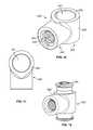
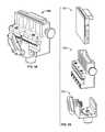
- FIG. 1is a front perspective view of an exemplary embodiment of an inserter attached to an expandable implant in its insertion configuration.
- FIG. 2is a partially exploded perspective view of the implant and inserter illustrated in FIG. 1 .
- FIG. 3is a distal end perspective view of the implant and inserter illustrated in FIG. 1 .
- FIG. 4is a partially exploded perspective view of the proximal end of the inserter illustrated in FIG. 1 .
- FIG. 5is a proximal end perspective view of an exemplary embodiment of an expandable interbody implant in its insertion configuration.
- FIG. 6is a lead end view of the expandable implant illustrated in FIG. 5 .
- FIG. 7is a side view of the expandable implant illustrated in FIG. 5 .
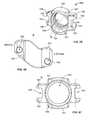
- FIG. 8Ais a proximal end perspective view of the bottom of an exemplary embodiment of an expandable spacer in its implanted configuration.
- FIG. 8Bis a superior view illustrating an expanded spacer resting on a vertebral endplate.
- FIG. 9is a posterior view of an expandable spacer adjusted for lordotic angle illustrating a decreasing height from anterior to posterior.
- FIG. 10is a top view of the implant illustrated in FIG. 8 .
- FIG. 11is an exploded perspective view of the implant illustrated in FIG. 8 .
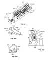
- FIG. 12is a front perspective view of an exemplary embodiment of a fastener pivot assembly.
- FIG. 13is a cross-sectional view of the fastener pivot assembly illustrated in FIG. 12 .
- FIG. 14is a front perspective view of an alternative coupling device.
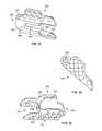
- FIG. 15is a top close up perspective view of teeth utilized on the endplate facing surface of the spacer.
- FIG. 16is a front perspective view of an exemplary embodiment of a coupling device.
- FIG. 17is a top view of the coupling device illustrated in FIG. 16 .
- FIG. 18is a front perspective view of an exemplary embodiment of a pivot coupler assembly.
- FIG. 35is an outside view of the link illustrated in FIG. 34 and illustrating lumbar angle L.
- FIG. 36is a top view of the link illustrated in FIG. 34 .
- FIG. 37is an inside perspective view of an exemplary embodiment of a medial intermediate link of the implant.
- FIG. 38is an inside perspective view of an exemplary embodiment of a medial distal link of the implant.
- FIG. 40is a top view of the medial distal link illustrated in FIG. 38 .
- FIG. 41is an outside perspective view of the medial distal link illustrated in FIG. 38 .
- FIG. 44is a bottom view of the lateral distal link illustrated in FIG. 42 .
- FIG. 45is an outside perspective view of the lateral distal link illustrated in FIG. 42 .
- FIG. 48is a side view of the control frame illustrated in FIG. 46 .
- FIG. 49is a cross-sectional view of the control frame illustrated in FIG. 46 along axis M-M.
- FIG. 52is a proximal end close up view of the expansion limiter mount.
- FIG. 53is front perspective view of an exemplary embodiment of the handle collar assembly.
- FIG. 54is an exploded view of the handle collar assembly illustrated in FIG. 53 .
- FIG. 56is a rear perspective view of an exemplary embodiment of an expansion handle.
- FIG. 58is a front perspective view of an exemplary embodiment of a graft inserter assembly.
- FIG. 60is an exploded view of a cartridge retainer portion of graft inserter assembly of FIG. 58 .
- FIG. 63is a rear perspective view of a cartridge retainer housing body.
- FIG. 65Cis a close-up perspective view of a chute door residing in a chute door recess.
- FIG. 68is an exploded view of a graft cartridge portion.
- FIG. 70is a top perspective view of a graft delivery guide portion of the graft inserter assembly.
- FIG. 84Aillustrates a paddle sizer
- FIG. 85illustrates sliding spacer on to the control arms of the insertion instrument and advancing fixation tube threads to secure spacer to the insertion instrument.
- FIG. 86illustrates pre-setting of the handle collar assembly on the control frame by the arrow pointing to no gap between rotating collar and inserter.
- FIG. 87Aillustrates an expansion rod
- FIG. 87Billustrates threading of the expansion rod through inserter and into coupler link.
- FIG. 88illustrates mounting expansion handle over the handle collar.
- FIG. 89illustrates rotation of the expansion handle to transition spacer to expanded configuration.
- FIG. 90illustrates confirmation of full spacer expansion as indicated by indicia on control frame by the arrow pointing to green indicator appears below collar.
- FIG. 91illustrates removal of expansion handle from handle collar.
- FIG. 92illustrates derotation of expansion rod to release it from the coupler for removal.
- FIG. 93A and FIG. 93Billustrate re-setting the handle collar assembly.
- FIG. 94illustrates the graft funnel inserted on the inserter.
- FIG. 95illustrates derotation of the lockwheel for removal of the instruments from the spacer.
- FIG. 1illustrates an exemplary embodiment of an expandable spacer and insertion assembly 101 with the spacer 100 in its insertion configuration and mounted to spacer inserter 300 .
- FIG. 2illustrates a partially exploded view of each portion of assembly 101 including spacer 100 , control frame 301 , handle collar 302 , fixation tube 303 , expansion rod 304 , expansion limiter 305 , and expansion handle 306 .
- FIG. 3is a distal end view of assembly 101 illustrating the small diameter profile when assembly 101 is in its insertion configuration.
- FIG. 5-7A closer view of spacer 100 in its insertion configuration is illustrated in FIG. 5-7 .
- the spacer 100comprises a proximal end 102 , a distal end 103 , a lateral side 104 , a medial side 105 , and support face 107 with opposing support face 106 .
- Teeth 108are inscribed on support face 106 and support face 107 and are configured to embed in the superior and inferior vertebral endplates to prevent migration of spacer 100 once the spacer is placed in its predetermined location between the vertebral bodies.
- FIG. 15illustrates teeth 108 which comprise a penetrating face 112 that is sufficiently narrow or pointed to penetrate the bone of the endplate, and positional faces 113 that upon penetration abut the bone and prevent migration across the endplate.
- the penetrating faces 112have a small square footprint and the positional faces 113 have a sloped rounded pyramid profile.
- Positional faces 113 of teeth 108broaden as they move away from the penetrating face 112 therein increasing anti-migration strength as spacer 100 settles into the endplate.
- a valley face 114seats against the bone as a limit to subsidence of the spacer 100 into the bone.
- Teeth 108 in this embodimentare manufactured using a rounded cutter spaced 90 degrees apart.
- the spacer 100Leading the distal end 103 of spacer 100 is nose 109 .
- the noseis configured for eased entry into the intervertebral space and may include tapered 110 and/or rounded 111 surfaces to ease the spacer 100 between the vertebral bodies and by pass soft tissue during entry.
- spacer 100assumes a narrow, compact, elongated form in order to minimize the size of the incision required for entry into the intervertebral space.
- the spacer 100 in this embodimenthas a generally rectangular profile with support faces 106 , 107 longer in length than the lateral 104 and medial 105 sides.
- the support faces 106 , 107are sloped to fit a predetermined lumbar angle between the patient's vertebrae as can be seen in FIG. 9 wherein the anterior links of spacer 100 slope to greater heights moving towards the posterior links.
- the vertebral bodyis strongest near the periphery of the endplate while the endplate profile is often described as oval, lima bean, or ‘race track’ shaped. Better fusions and overall better results are achieved when the interbody spacer is configured to rest on this dense bone near the endplate periphery while providing a large central graft aperture for the packing of bone graft. Therefore, in its expanded configuration, it is preferred that the outer perimeter of spacer 100 approximate the profile of the vertebral endplate as illustrated in FIG. 8A . Spacer 100 is illustrated in its expanded configuration in FIGS. 8-10 . In this preferred embodiment, the spacer comprises seven links and forms an irregular hexagon to generally assume the outer endplate ‘racetrack’ profile. In other embodiments, the number of links utilized in the spacer may vary.
- FIG. 11illustrates an exploded view of spacer 100 which is comprised of a plurality of links joined by joints 130 .
- the linkscomprise insertion link 115 with central axis ‘A’ located at proximal end 102 of spacer 100 which serves as the site of attachment for inserter 300 .
- Central axis ‘A’is configured to be generally collinear with the surgical access path. For example, if spacer 100 was configured for a lateral surgical approach, insertion link 115 would preferably be placed lateral with central axis ‘A’ directed along a lateral direction.
- spacer 100is configured for surgical insertion into the intervertebral space along a transforaminal surgical path indicated as ‘P’ in FIG. 8B .
- Insertion link 115is therefore positioned posterior laterally and axis-A is directed in a posterior lateral direction.
- the spacer 100 in this embodimentis configured for use from either the left or right side of the spine wherein a support face 140 or 141 that faces superior when inserted from one side will face inferior when inserted from the other. Consistent with the transforaminal surgical approach, spacer 100 is inserted with a definitive medial and lateral side therein assuring alignment of the inserter link with the surgical path regardless of left or right side entry.
- Joints 130provide movement between each link portion 115 - 121 in a plane generally parallel to the intervertebral space.
- the jointsmay assume any variety of forms such as ball and socket, snap, hinge, or a pin or knuckle joint.
- Pin jointsare utilized in the preferred embodiment and each link portion 115 - 121 comprises one or more capture tongue 158 configured to reside within a complementary capture groove 157 ( FIG. 31,33 ) on an adjacent link portion 115 - 121 to form an endless chain. In the expanded configuration, this chain of links defines a graft aperture 122 available for packing with bone graft or other bone substitute.
- Each link portion 115 - 121 of spacer 100may share a plurality of common features not necessarily labeled on each link.
- each linkis formed from a body 167 , each link except for the inserter link has teeth 108 , and link support faces 140 , 141 are common to each link and abut the endplates therein maintaining the predetermined intervertebral space.
- Adjacent links 115 - 121comprise a capture groove 157 and a capture tongue 158 aligned within said groove to form a joint 130 .
- Two capture walls 154 & 155define capture groove 157 .
- the interior of capture groove 157comprises one or more capture surfaces 159 - 160 ( FIG. 28,30 ).
- Capture tongue 158( FIG. 34 ) comprises opposing guide surfaces 161 and 162 .
- Pin wall 163extends vertical through capture tongue 158 and capture walls 154 & 155 therein defining pin aperture 164 with central axis-B.
- Joints 130are formed by configuring a capture tongue 158 within capture groove 157 and aligning axis-B. Pivot pins 129 are then pressed into pin apertures 164 except with insertion link 115 wherein shortened pivot pins 128 are utilized within pin apertures 164 ( FIG. 26 ).
- Each link 115 - 121 in this embodimentis configured with a pre-determined profile suitable to performing in the insertion configuration, the expanded configuration, and transitional configurations therebetween.
- FIG. 26illustrates a generally S-shaped profile of the insertion link 115 from a top view.
- a plurality of positional stops 165 interfering with each otherare configured to limit motion at each joint when spacer 100 moves from an insertion configuration to an expanded configuration. These positional stops 165 determine the final shape of the expanded implant. In the preferred embodiment for example, the positional stops 165 help guide the implant into the open generally hexagonal profile of FIG. 10 .
- the insertion link 115comprises a pair of opposing capture tongues 158 .
- a control guide 144is situated on insertion link 115 and in this embodiment is in the form of a pair of opposing grooves 145 cut parallel to axis-A through each control tongue 158 .
- the groovesare configured to accept control arms 350 of inserter instrument 300 when mounted to insertion link 115 .
- the grooves 145comprise surfaces 146 , 143 , and 142 upon which surfaces on control arms 350 act to impart forces and direction on the insertion link 115 .
- An inner wall 151 extending along axis-Adefines inserter aperture 149 .
- Inner wall 151may be threaded 150 for threaded attachment of insertion instrument 300 .
- instrument stop surface 156At the proximal end of insertion link 115 is instrument stop surface 156 which abuts instrument 300 when attached to insertion link 115 .
- the lateral-proximal (LP) link 121is illustrated in FIGS. 28-30 .
- This linkis connected by pin joint to the lateral side of inserter link 151 .
- LP link 168comprises two capture grooves 157 .
- the deeper capture groove 157is configured to house the elongated capture tongue 158 of insertion link 115 when elongated wall 169 of LP link abuts positional stop 165 in the insertion configuration.
- instrument channel 170Situated on the inside of link 168 . This channel accommodates portions of instrument 300 when spacer 100 is in the collapsed insertion configuration.
- FIGS. 31-33illustrate an embodiment of a medial proximal (MP) link Unlike LP link 121 , the MP link 116 comprises both a capture groove 157 and a capture tongue 158 . Some embodiments of the MP or LP links include an extension of control guide 144 in the outer surface of the link to accommodate control arms 350 of inserter instrument 300 .
- FIGS. 34 & 35Various embodiments of the lateral intermediate (LI) link 120 is illustrated in FIGS. 34 & 35 , and of the medial intermediate link (MI) 117 in FIGS. 36 & 37 .
- the embodiments shownillustrate an angulation between support face 140 and 141 to replicate the lumbar angle ‘L’ typically encountered between the endplates.
- This angulation between support facesmay be adjusted on any of the spacer links according to the anticipated final position within the intervertebral space. For example, if a link resides obliquely within the intervertebral space, then support faces may be angled accordingly to match the intervertebral space at this orientation.
- LI link 120utilizes a capture tongue 158 on each side of the link whereas the MI link 117 utilizes one capture tongue 158 and one capture groove 157 .
- One or more windows 171may be cut through the body 167 of link 117 , 120 between the inner 172 and outer 166 surface of the link.
- FIGS. 38-41illustrate various aspects of an exemplary embodiment of medial distal (MD) link 118 of spacer 100 .
- the MD linkcomprises a body 167 formed in the general shape of the number six. At one end, is a capture groove 157 utilized for creating a joint with adjacent MI link 117 .
- On one side of MD link 118is an extensive support face 140 with teeth 108 inscribed thereon.
- On an opposing sideis a smaller support face 141 .
- pocket 174Situated between outer surface 166 and aperture 173 is positioner pocket 174 .
- Pocket 174is configured with a support floor 176 , containing wall 177 , and stop wall 179 .
- coupler window 175Situated between inner surface 178 and aperture 173 is coupler window 175 .
- Cut into body 167is instrument channel 170 to accommodate portions of instrument 300 when spacer 100 is in its insertion configuration.
- the body 167 of MD link 118 and LD linkinclude a mating cutaway 182 defining mating surface 181 .
- MD link 118 and LD link 119are aligned on axis-C with mating surface 181 of each link in facing opposition.
- FIGS. 42-45illustrate various aspects of an exemplary embodiment of lateral distal (LD) link 119 of spacer 100 .
- the LD linkcomprises a body 167 formed in the general shape of the number six. At one end, is a capture groove 157 utilized for creating a joint with adjacent LI link 120 .
- One side of LD link 119comprises an extensive support face 140 with teeth 108 inscribed thereon. On an opposing side is a smaller support face 141 .
- pocket 174Situated between outer surface 166 and aperture 173 is positioner pocket 174 .
- Pocket 174is configured with a support floor 176 , containing wall 177 , and stop wall 179 .
- Inscribed into support floor 176is a C-shaped groove 180 .
- coupler window 175Situated between inner surface 178 and aperture 173 is coupler window 175 .
- Cut into body 167is instrument channel 170 to accommodate portions of instrument 300 when spacer 100 is in its insertion configuration.
- the body 167 of MD link 118 and LD link 119include a mating cutaway 182 defining mating surface 181 .
- MD link 118 and LD link 119are aligned on axis-C with mating surface 181 of each link in facing opposition.
- FIG. 23illustrates positioner coupling assembly 204 which is comprised of; fastener pivot assembly 200 illustrated in FIGS. 12 and 13 , positioner gear assembly 205 illustrated in FIG. 22 , and coupler 206 illustrated in FIG. 16 .
- Fastener pivot assembly 200secures MD link 118 and LD link 119 together and in this embodiment is in the form of a shoulder bolt 232 releasably attached to shoulder nut 233 through threaded interengagement 231 .
- fastener pivot assembly 200may be in other forms such as a rivet or a bolt threaded into the aperture of the opposing link
- Bolt 232 and nut 233comprise opposing restraining faces 234 that secure links 118 and 119 together when nut 233 is advanced.
- the shoulders 230 on nut 233 and bolt 232center links 118 and 119 along axis C.
- Coupler 206comprises a rounded body 240 with pivot aperture 241 extending through body along axis D.
- a coupling aperture 242extends along axis-E and is generally perpendicular to axis-D.
- the wall defining the coupling aperture 242is threaded for engagement with expansion rod 304 .
- Stop surface 243abuts an opposing surface on expansion rod 304 indicating the rod is fully engaged in coupling aperture 242 .
- Centering surface 244encircles the outer body 240 about axis D. In an assembled configuration, end surfaces 245 position coupler 206 between the MD and LD links 118 & 119 .
- Positioner gear assembly 205is configured to hold spacer 100 in a predetermined expanded or collapsed configuration.
- Assembly 205comprises an arc shaped integral spring positioner gear 209 mated with a complementing positioner gear 207 as illustrated in FIG. 22 .
- spring positioner gear 209comprises a biasing element here in the form of an integrated undulating spring 208 or equivalent biasing member. Providing the space required to compress is compression gap 223 and limit face 224 abuts and stops further compression at support floor 176 to prevent plastic deformation of spring 208 .
- a foot 210 of spring 208resides against support floor 176 of MD link 118 .
- spring 208may be in the form of a ‘Y’ as seen in FIG. 24 wherein the foot 210 is at the tip of arms of the Y, or other forms such a separate compression spring or leaf spring.
- the positioner gears 209 and 207comprise an arc shaped body 211 with radially cut teeth 212 cut into face wall 222 .
- a convex outer wall 213opposes a concave inner wall 214 sized to fit around centering surface 244 of coupler 206 .
- At the ends of each arcare position faces 215 .
- positioner gear 207comprises a seat face 216 opposite teeth 212 . Stepping below the seat face 216 is inner rim 217 comprising an outer position face 219 , an inner position face 220 , bottom face 218 , and top face 221 .
- inner rim 217 of positioner gear 207resides in C-shaped groove 180 of LD link 119 with seat face 216 directly adjacent support floor 176 .
- End surface 245 of coupler 206abuts against top face 221 to keep positioner gear 207 captured in positioner pocket 174 .
- Position faces 215 of positioner gearsare bound by stop walls 179 therein causing positioner gear 207 or 209 to rotate about axis C only as part of rotational movement of MD and LD links 118 and 119 .
- Axis-E and coupling aperture 242 of coupler 206reside within the coupler windows 175 of the MD and LD links with room to pivotably adjust as spacer 100 moves from an insertion configuration to an expanded configuration.
- instrument 300creates a tension force on coupler 206 drawing it near insertion link 115 .
- MD link 118 with captured spring positioner gear 209 housed within positioner pocket 174 and LD link 119 with positioner gear 207 captured within its own positioner pocket 174rotate about axis-C in opposite directions.
- This rotational motioncauses the opposing radial cut teeth 212 to move from a tip 225 to valley 227 orientation, to a tip 225 to tip 225 orientation therein imparting a translational motion of spring positioner gear 209 against spring 208 .
- Continued rotationwill cause tip 225 to seat in a new valley 227 .
- This mechanical arrangementprovides the surgeon a means to selectively expand or contract spacer 100 to predetermined positions once the instrument 300 imparts a sufficient tension or compression force on coupler 206 .
- spacer 100will remain in the predetermined expanded configuration once instrument 300 is removed as the patient's anatomy will be unable under normal circumstances to create forces on spacer 100 sufficient to overcome biasing force of spring 208 .
- a nitinol leaf springis configured about centering surface 244 of coupler with each leg of the leaf spring extending into the body of MD link 118 and LD link 119 . Said spring biases link 118 and 119 towards an expanded configuration with inserter 300 configured to work against bias force to keep spacer 100 in insertion configuration during insertion.
- the inserter 300comprises a control frame 301 with proximal end 331 and distal end 330 and is illustrated in FIGS. 46-57 .
- the frame 301comprises an elongated body 339 with an interior wall 340 defining a central working aperture 332 sized for gliding passage of fixation tube 303 and expansion rod 304 ( FIG. 2 ).
- the outer wall 380extends from the distal end 330 with a rectangular profile similar to spacer 100 in the insertion configuration. Extending from the distal end 330 of body 339 are one or more control arms 350 sized to be received within the opposing grooves 145 of control guide 144 of insertion link 115 .
- the control arms 350comprise a plurality of torque walls 341 facing surfaces 142 and 143 on insertion link 115 and are configured to transmit a torsional force to the insertion link 115 .
- Surfaces 146 of the inserter linkare captured between opposing walls 342 therein aligning axis-A of inserter link with axis-F of control frame 301 .
- Outer surfaces 343 of the control armsare sloped to minimize resistance against soft tissue during insertion and tip 345 is rounded for the same purpose.
- Link face 344is secured against stop surface 156 when spacer 100 is attached to spacer inserter 300 .
- link face 344 and stop surface 156comprise complementary non-planar surfaces assuring proper alignment of spacer and inserter (i.e. lateral side 104 of spacer and side marked ‘lateral’ on inserter 300 are co-aligned).
- Proximal to control arms 350are one or more windows 338 cut into body 339 to enhance cleaning after use.
- a counter-torque neck 333for attachment of a counter torque instrument.
- the counter-torque neck 333is in the form of a plurality opposing torque faces 346 wherein an instrument as simple as an open ended wrench may attach and limit torsional forces transmitted to the implant through inserter 300 .
- a bulb portion 347 of body 339is also at proximal end 331 of control frame 301 . Cut into bulb portion 347 is lock aperture 335 configured to house lock wheel 348 . Two sides of bulb 347 are substantially flattened into opposing finger faces 337 to provide access by the user's fingers to lock wheel 348 .
- collar neck 334Proximal along axis-F of body 339 from bulb portion 347 is collar neck 334 comprising threads 349 thereon configured for engagement with handle collar 302 .
- indicator 351here illustrated in the form of a groove. The groove may be painted or otherwise highlighted.
- limiter neck 336Located proximal to collar neck 334 of body 339 is limiter neck 336 .
- the limiter neckcomprises a proximal wall 352 , a centering wall 353 , a locator wall 354 , and a limiter groove 355 . In some embodiments limiter neck 336 is absent.
- Handle collar 302 assemblyis illustrated in FIGS. 53 and 54 and comprises an outer drive collar 367 and inner spin collar 366 .
- the outer drive collar 367comprises a central aperture 369 with threaded walls 360 configured for threaded engagement over threads of collar neck 334 .
- aperture 369is enlarged to house inner spin collar 366 .
- collar groove 359for seating expansion ring 368 .
- Ring 368also encircles inner spin collar 366 within ring groove 361 therein securing inner spin collar 366 within outer drive collar 367 but providing for free rotation of one collar about the other.
- Outer collar 367also comprises a distal stop surface 355 which when abutted against bulb portion 347 is configured as the starting point for collar 367 prior to transitioning spacer 100 from insertion configuration to expanded configuration.
- Drive 370Distally on outer collar 367 is drive 370 configured for moving collar by attachment of expansion handle 306 .
- Drive 370 in this embodimentis in the form of several flat drive surfaces 357 formed in a hexagon encircling central aperture 369 . Cut into each drive surface 357 is lock aperture 358 .
- Proximal to inner threaded walls 360is inner surface 356 sized to house outer surface 364 of inner spin collar 366 .
- Inner spin collar 366further comprises a spin aperture 362 defining an inner surface 365 enlarged to ride slightly above collar neck 334 threads. At proximal end of spin collar 366 is limiter surface 363 .
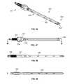
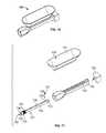
- Fixation tube 303is further illustrated in FIG. 55 .
- the tube 303comprises a linear elongated body with inner cannula 371 extending the length of the tube and cannula sized to house fixation rod 304 to slide therein.
- the outer surface 373 of tube 303 at the distal endis configured with threads 372 for threaded engagement with threads 150 of insertion link 115 .
- tube 303is perforated with pin apertures.
- Fixators 374 in the form of fixation pinsextend through lockwheel 348 and are housed within said pin apertures to fix lockwheel 348 in a predetermined location on tube 303 wherein when tube 303 is housed within control frame 301 , lockwheel 348 freely spins within lock aperture 335 .
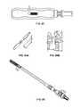
- FIGS. 2 and 4further illustrates expansion rod 304 .
- Protruding from the distal end of rod 304is a threaded boss 375 configured for threaded engagement within coupling aperture 242 .
- Stop surface 376abuts stop surface 243 of coupler 206 when rod 304 is fully engaged within aperture 242 .
- rod 304decreases in diameter.
- the expansion limiter 305prevents over expansion of spacer 100 when transitioning to the expanded configuration by limiting travel of expansion rod 304 .
- the limiter 305comprises a housing 315 with non-circular inner aperture 377 complementing profile of limiter neck 336 for sliding translational movement but not rotary. Cut into side of housing 315 is clip slot 378 configured for sliding entry of clip 318 therein securing housing 315 to expansion rod 304 proximal to step 320 .
- Lock button 316is housed in a button aperture 394 on side of housing (not viewable). Lock button 316 comprises elongated slot 317 wherein a rib (not viewable) within slot 317 releasably engages limiter groove 355 of control frame 301 . Biasing member 379 keeps rib engaged in groove 355 until lock button 316 is depressed by user providing for release of limiter 305 from limiter neck 336 .
- Expansion handle 306comprises a T-shaped body 321 as illustrated in FIGS. 56-57 and FIG. 4 .
- head recess 381sized to house enlarged head 310 of expansion rod 304 .
- head shelf 384At the base of the head recess 381 is head shelf 384 to capture head 310 in head recess 381 .
- head shelf 384is a narrowed neck slot 382 to provide passage of the elongated rod body of expansion rod 304 .
- Distal to head shelf 384is limiter recess 385 configured to house expansion limiter 305 .
- Collar recess 386is situated distal to limiter recess 385 , and is configured to fit over handle collar assembly 302 .
- the collar recess 386is bounded by two opposing collar drive surfaces 387 and a collar shelf 383 . Cut through collar shelf 383 is control aperture 388 sized to pass collar neck 334 of control frame 301 while simultaneously capturing outer drive collar 367 .
- This open configuration of head recess 381 , neck slot 386 , limiter recess 385 , collar recess 386 , and control aperture 388provide the means for rapid sideways removal of expansion handle 306 from the inserter 300 .
- handle 306With handle 306 connected to inserter 300 , torsional force applied by user to handle is transmitted through collar drive surfaces 387 to drive surface 357 of outer drive collar 367 therein causing handle collar assembly 302 to advance proximal or distally along with expansion rod 304 further causing spacer to transition between insertion and expanded configuration.
- Each lock 307releasably secure expansion handle 306 to handle collar 302 .
- Each lock 307comprises a lock lever 389 and bias member 312 in the form of a coiled spring.
- the lock lever 389 in this embodimentis in the shape of a teeter-totter comprising a pivot member 313 in the form of a pin, and a plunger 314 .
- Lock lever 389resides in lever recess 311 within body 321 of handle 306 .
- the lever 389is pinned into recess 311 by pivot member 313 extending between pivot apertures 309 and through body of lever 389 .
- Spring force produced by bias member 312causes plunger 314 to occupy plunger hole 310 and extend into collar recess 386 while simultaneously filling lock aperture 358 of outer drive collar.
- the handleis removed by the user by placing finger force on lever release surfaces 308 therein causing plungers 314 to retract and sliding handle 306 away.
- window 390On the rear side of expansion handle 306 is viewing window 390 cut between the outer wall of body 321 into limiter recess 385 .
- window 390provides a more intuitive method for viewing progress of spacer 100 transition from one configuration to another by noting position of limiter within window 390 .
- head drive pocket 391is integral to expansion handle 306 . This pocket 391 is configured with drive faces 392 complementing enlarged head 310 of expansion rod 304 wherein when handle 306 is removed from collar 302 , it can be used to apply greater torque to head 310 when necessary.
- the insertion instrumentmay be removed and a graft filling instrument may be attached to insertion link 115 .
- This instrumentmay be the form of an upright funnel with an elongated plunger at the proximal end, wherein the plunger pushes graft material down an elongated tube extending to the insertion link and into graft aperture 122 .
- a graft inserter assembly 500is illustrated in FIG. 58 .
- the graft inserteris configured to cooperate with the spacer & insertion assembly 101 to introduce bone graft into graft aperture 122 of spacer 100 .
- the inserter 500comprises a graft cartridge portion 501 , a cartridge retainer portion 502 , and a graft delivery guide portion 503 .
- the graft cartridge portion 501 in this embodimentis further illustrated in FIGS. 66-68 . It comprises a chute housing 504 , a cartridge door 505 , and cartridge handle 506 .
- the housing 504is formed of a flat rectangular body 537 with a plurality of chutes 507 , in this case partially opened, traveling from a proximal end top surface 516 to a distal end bottom surface 518 of chute housing 504 .
- the chutes 507have a chute wall 508 defining a cylindrical aperture configured for storage of graft and passage of a plunger to push the graft material in the chutes 507 from a proximal end to a distal end of the chute.
- the plungerfor example, may be in the form of the expansion rod 304 described earlier but with a blunt tip and length sufficient to push bone graft from the chutes 507 into graft aperture 122 of spacer 100 .
- the chutes 507may be open on one side along their length and separated by chute divider surface 509 .
- a handle 506is fixed to chute housing 504 , here by means of fixing pins 510 holding posts 511 in bores 512 located on the opposing side of chute housing 504 .
- Handle 506provides eased insertion and removal of chute housing 504 from cartridge retainer portion 502 .
- a lock recess 513cooperates with a releasable lock 514 , here in the form of a spring pin on the cartridge retainer 502 to secure chute housing 504 within retainer 502 .
- a pair of opposed channels 515are situated within side wall 517 . The channels 515 cooperate with bosses (not shown) within the cartridge retainer 502 to assure the chutes are properly centered within the retainer for the transfer of graft material therethrough.
- a cartridge door 505here in the shape of a flat square, comprises a hinge channel 519 for cooperation with hinge channel 520 and hinge pins 521 .
- the graft cartridge 501may be placed on a table laying on handle 506 with the graft door 505 opened therein exposing the open chutes 507 . Graft is then spread across the chute divider surfaces 509 and massaged into the open chutes until they are full. Excess graft is wiped from surface 509 and the graft door 505 is closed. The graft cartridge 501 can then be inserted into the retainer portion 502 .
- FIG. 60illustrates an exploded view of a cartridge retainer 502 illustrated in FIG. 59 .
- the retainer 502comprises a cartridge retainer housing 522 with a rack gear 523 fixed to the housing with locator pins 531 and fasteners 530 .
- Releasable lock 514is mounted to housing 522 within lock port 535 and comprises a lock plunger 532 , plunger biasing member 533 here in the form of a spring, and a release knob 534 .
- the springbiases the plunger towards interfering with lock recess 513 of chute housing 504 to secure it within retainer housing 522 until surgeon desires to remove it.
- the cartridge retainer housing 522is further illustrated in FIG. 61-63 .
- the housingcomprises a body 540 with top face 541 , front face 542 , opposed side faces 543 , rear face 544 , and bottom face 555 .
- Linearly cut into the rear face 544is rear guide recess 545 bounded by a lower guide wall 546 and an upper guide wall 547 .
- cut into the front face 542is front guide recess 548 defining an upper foot 550 and lower foot 549 .
- the front guide recess 548is bounded by a lower guide wall 546 and an upper guide wall 547 .
- a cartridge aperture 550extends from the top face 541 through the body 540 and bottom face 555 and is configured in size and profile to house graft cartridge 501 .
- a handle recess 549is cut through the rear face 544 and top face 541 . It is here cartridge handle 506 resides and stop surface 551 abuts handle 506 when cartridge 501 is fully seated within the cartridge aperture 550 .
- On side face 543is auxiliary port 553 with plug 554 .
- chute door recesses 556Cut into front face 542 and bottom face 555 are chute door recesses 556 to provide housing of chute doors 527 .
- Base wall 560 and containment walls 557guide the chute doors 527 down a linear path and hold the doors within the recesses 556 .
- pin aperture 558At the end of the recesses 556 is pin aperture 558 to hold one end of door pin 524 .
- Each chute door recess 556is separated by a chute wall 559 .
- chute plate recess 561Also cut into front face 542 and bottom face 555 is chute plate recess 561 for housing of chute plate 528 .
- locator pin aperture 563 and threaded hole 562Located on base wall 564 of recess 561 .
- pin apertures 563 and threaded hole 562located on upper guide wall 547 are pin apertures 563 and threaded hole 562 for placement of rack gear 523 and securement with fasteners 529 .
- chute doors 527reside within the chute door recesses 556 .
- the chute door 527 in this embodimentcomprises an L-shaped body 565 with enlarged head 566 ( FIGS. 65A & 65B ).
- the chute door 527is configured to slide along door pins 524 and resides between base wall 560 , chute wall 559 , and containment wall 557 .
- the door 527comprises a pin aperture 567 for passage of door pin 524 and a counter bore 568 to house end of biasing member 525 .
- Chute door 527further comprises a pair of opposing side walls 571 , and bottom wall 570 . Graft face 569 of chute door 527 seals chutes 507 during operation until the chute door is retracted for graft removal.
- Retraction of individual chute dooris controlled by retraction face 573 which is sloped and rides in high door groove 611 of graft delivery guide 503 ( FIG. 70 ) and boss face 568 of boss 572 rides in low door groove 611 . Portions of this mechanism are illustrated in FIG. 64 wherein a portion of the chute doors 527 are retracted therein permitting release of graft (may be assisted by a chute plunger), and others are fully covering of chutes 507 .
- FIG. 69illustrates an exploded view of an exemplary embodiment of a graft delivery guide portion 503 of graft inserter 500 .
- the guide portion 503comprises a coupler 600 with a U-shaped body configured to hold cartridge retainer 502 on a base wall 602 and two opposing upright walls 601 . Projecting inward from each upright wall 601 is capture wall 603 .
- One capture wall 603is configured to be received within the rear guide recess 545 , and the other within the front guide recess 548 wherein cartridge retainer 502 is captured within coupler 600 .
- Pinion gear 608resides in pinion aperture 609 and is secured in place by pins 622 about pinion shaft groove 612 when pins are pressed into pin holes 621 .
- Pinion gear 608comprises a locking aperture 613 extending therethrough for housing locking pin 615 . Pinned to the end of the shaft of pinion gear 608 is handle 616 using pins 619 .
- the handle 616comprises a sliding lock button 618 pinned to handle 616 utilizing pin 617 .
- Sliding lock button 618comprises a sloped activation surface 620 configured to engage locking pin 615 wherein when button 618 is slid in one direction, activation surface 620 will cause locking pin 615 to travel towards cartridge retainer 502 and held within one selector hole 536 of cartridge retainer housing 522 therein locking it in position.
- button 618is slid in the opposite direction, a gap is created between activation surface 620 and locking pin 615 wherein spring 614 will cause locking pin 615 to be removed from selector hole 536 .
- the cartridge retainer housing 522is free to translate parallel to upright walls 601 .
- Indicator 613aligns with indicia 574 to indicate the specific chute 507 aligned with graft port 623 of cannulated fastener 605 .
- FIGS. 71-76a graft funnel 700 is illustrated in FIGS. 71-76 .
- FIG. 71illustrates an exploded view of graft funnel 700 . It comprises funnel 701 , collector tube 702 , plunger tube 704 , sealing spring 705 , ball 706 , detent spring 707 , and rotation knob 703 .
- Graft funnel 700comprises a broad open mouth 708 with inclined funnel walls 709 leading to an elongated funnel outlet 710 .
- Outlet fitting 711is configured for fit and secured in funnel inlet 712 of collector tube 702 .
- the collector tube 702comprises a tubular elongated body 713 with central aperture 714 along entire length of body 713 defining inner surface 718 .
- Proximal to threads 716is spring wall 719 serving as a fixation surface for spring 705 .
- grip 715configured with ribs, knurling or other feature to ease user insertion of funnel 700 on the inserter.
- opposing ears 721At the proximal end are opposing ears 721 with a blind hole 717 drilled from one side of the ear to house a ball detent mechanism 706 , 707 cooperating with plunger tube 704 .
- Proximal face 720faces rotation knob 703 .
- Plunger tube 704comprises an elongated body 727 with central aperture 728 defining inner collector wall 730 .
- Aperture 728is sized to pass plunger type expansion rod for pushing graft toward spacer 100 .
- At the distal endis enlarged head 725 terminating with inserter face 726 .
- Graft inlet window 729provides for passage of graft material from funnel 701 into central aperture 728 .
- Proximal to graft inlet window 729is an elongated detent groove 724 for cupping ball 706 that provides a small amount of translation of plunger tube 704 within collector tube 702 .
- An opposing detent groove 724is mirrored on opposing side of plunger tube 704 .
- This ball detent system with elongatednot only holds plunger tube 704 within collector tube 702 , it also provides the users a means to quickly align the graft inlet window 729 with funnel outlet 710 to provide for graft placed into funnel 701 to flow into and fill central aperture 728 of plunger tube 704 .
- Knob 703comprises central aperture 722 having aperture walls configured to act on torsion faces 723 of plunger tube 704 . A 180 degree turn of knob 703 by the user will in turn rotate plunger tube 704 to opposing ball detent groove 724 therein sealing off the central aperture 728 of plunger tube 704 .
- Knob 703further comprises a widened aperture 731 at its proximal end through which expansion rod style plunger, as described earlier, is utilized to push the graft housed in the plunger tube 704 , through the fixation tube 303 and into graft aperture 122 .
- FIGS. 77-79illustrate spacer template 800 .
- Individual template instruments 800correspond to specific spacer 100 sizes and are used as a quick method of validating the fit of a spacer 100 prior to implantation in the intervertebral space.
- Template 800comprises a template spacer 801 further comprised of a series of pinned template links 802 generally replicating links 116 - 121 of spacer 100 with a few differences.
- teeth 108 on spacer 100are absent and replaced with a smooth surface 804 to provide eased insertion and removal of template 800 in and out of the intervertebral space.
- Windows 171 extending through inner surface 172 of select linksmay be removed.
- coupler 206is now integrated into expansion rod 806 and positioner gears 207 and 209 are removed.
- the functionally equivalent MD and LD links 118 , 110 in the template spacerhave been modified accordingly to house coupler 807 of expansion rod 806 .
- Expansion rod 806comprises an elongated body 829 .
- the distal end of the rod 806flattens into coupler 807 generally comprising a round disc with central aperture sized to house a fastener similar to fastener pivot assembly 200 used to secure links and coupler together.
- coupler 807generally comprising a round disc with central aperture sized to house a fastener similar to fastener pivot assembly 200 used to secure links and coupler together.
- torsion featureshere in the form of a male flat 808 , to inter-attach rod 806 within corresponding female flat 825 within expansion drum 810 .
- Pin 812secures drum 810 to rod 806 through pinhole 809 .
- the outerbody of expansion drum 810Located on the outerbody of expansion drum 810 , preferably at the proximal end is indicator 811 that is viewable through window 815 of handle 814 to monitor expansion progress of template spacer 801 .
- the outerbody of expansion drum 810comprises threads complementing threads 826 within drum aperture 817 .
- retainer groove 816At the distal end of drum aperture 817 is retainer groove 816 sized to house a portion of spring retainer ring 813 .
- Control tube 803comprises an elongated body 821 with central rod aperture 824 extending therethrough and sized to house sliding expansion rod 806 therein.
- retainer groove 819formed within control tube head 818 .
- the retainer groove 819is also configured to house a portion of spring retainer ring 813 wherein the ring holds handle 814 to control tube head 818 yet provides for rotational movement therebetween.
- torsional flats 820for attachment of a counter torque device such as an open end wrench or similar device.
- link control head 828At the distal end of control tube 803 is link control head 828 .
- the headcomprises one or more bosses 823 each having an integrated pin aperture 827 .
- control head 828is held with pins 822 to the corresponding template spacer links 802 .
- the corresponding insertion link 115is integrated into control tube 803 of spacer template 800 since the template links are not required to be released from the template instrument.
- control tube 803may be configured to be releasable from various spacer templates 800 .
- the outer surface of the control tubemay include indicia 830 to indicate instrument orientation (i.e. medial or lateral). By rotation of handle 814 , spacer template 800 is capable of transforming template spacer 801 between insertion and expanded configurations.
- the spacer 100 and methodare configured for a transforaminal surgical approach.
- the patientis placed on a radiolucent surgical table in the prone position.
- a retractoris positioned over the pre-determined operative level.
- Anatomic landmarksare identified followed by initial incisions localized at the disc space using fluoroscopy in the anterior/posterior (A/P) and lateral views.
- a radiographis taken and additional radiographs are taken at any time at the surgeon's discretion.
- the patient's pediclesare targeted above and below the affected level and the location of each is marked.
- a skin incisionis made between the pedicle markings with sizing appropriate for the retractor used.
- tissueis released from the facet joint at the affected level. Fascia or tissue at the pedicles preventing placement of the retractor is removed.
- the retractoris inserted over the facet joint and positioned and secured to be parallel to the disc space for the proper medial exposure trajectory.
- the surgeonthen performs a conventional facetectomy and decompression followed by annulotomy and discectomy. Using any combination of pituitary rongeurs, disc cutters, endplate scrapers, curettes, and rasps, the surgeon removes as much disc material from the disc space as possible. A variety of angled instruments are then used to prepare the contralateral/posterior and ipsilateral/anterior regions of the disc. The endplates are prepared to remove cartilage and expose bleeding subchondral bone.
- An appropriately sized spacer template 800with template spacer 801 in the collapsed configuration is selected and inserted down the surgical path at an oblique angle with the “MEDIAL” and “LATERAL” markings 830 on the instrument in the correct orientation relative to the patient's spine.
- the templateis inserted until the distal tip 831 of spacer 801 abuts the annulus at the anterior/contralateral region of the disc space ( FIG. 80 ).
- the distal tip 831is confirmed to be abutting the anterior annulus.
- anterior-posterior (A/P) fluoroscopythe distal tip is checked to assure it abuts the projected medial border of the contralateral pedicle. If necessary, a surgical mallet is used to impact the proximal end of handle 814 until it reaches the desired location.
- the handle 814 of template 800is advanced by clockwise rotation to expand the template ( FIG. 81 ).
- Full expansioncan be confirmed via fluoroscopy as the notches on the expanded template will be coincident in the direct A/P and direct lateral views as indicated in FIG. 82 .
- Full expansioncan be confirmed via visual indicator on the footprint template handle as illustrated in FIG. 83 .
- the spacer template 800is transitioned prior to removal by rotating the template handle counter-clockwise until it returns to a collapsed insertion configuration.
- the surgeonwill choose an alternate sized spacer template if necessary until the proper spacer template size has been determined using tactile feel and fluoroscopy. Additional disc tissue may be removed as needed to facilitate full expansion.
- An appropriately sized paddle sizeris then chosen as illustrated in FIG. 84 .
- a T-handleis attached to the end of the sizer and inserted into the disc space using an oblique trajectory.
- Appropriate “MEDIAL” and “LATERAL” instrument markingsare followed if the sizer is rotated to height relative to the patient. The sizing iterations are continued until the proper height and lordosis have been determined using tactile feel and lateral fluoroscopy.
- Handle collar assembly 302is advanced on collar neck 334 of control frame 301 until distal stop face 355 abuts bulb portion 347 of control frame 301 as illustrated in FIG. 86 .
- An optional expansion limiter 305may be attached to limiter neck 336 .
- An appropriately sized expansion rod 304 corresponding to the spacer 100 sizeis selected. Using enlarged head 310 , and leading with threaded boss 375 , the expansion rod 375 is advanced through working aperture 332 of control frame 301 and threaded (clockwise) into coupler aperture 242 of coupler 206 until stop surface 243 abuts stop surface 376 on expansion rod 304 as illustrated in FIG. 87 . Expansion handle 306 is then mounted over outer drive collar 367 while spacer 100 remains in the insertion configuration as illustrated in FIG. 88 .
- Spacer 100is then inserted down the surgical path into the disc space using an oblique trajectory while ensuring that the “MEDIAL” and “LATERAL” indicia 393 are in the correct orientation relative to the patient.
- the implantUnder fluoroscopy, the implant is expanded through rotation of the expansion handle as illustrated in FIG. 89 , while a distal directed force is maintained during expansion and the anterior aspect of the implant in monitored via fluoroscopy to assure it remains in the desired location. Tactile resistance may be felt when the implant is in its fully-expanded state. Full expansion can be confirmed via fluoroscopy as well as by visual indicator 351 on the implant inserter as seen in FIG. 90 . Radiographs may be taken to confirm correct placement of spacer 100 in the intervertebral space.
- handle 306may be derotated to return to the insertion configuration for spacer 100 removal or readjustment. When fully collapsed, the rotating collar on the inserter will be fully seated distally. Once proper placement is achieved, expansion handle 306 is removed from spacer inserter 300 by releasing handle lock 307 (if so equipped) and sliding handle 306 off as seen in FIG. 91 .
- the expansion rod 304is released from coupler 206 through derotation of enlarged head 310 as illustrated in FIG. 92 .
- the handle collar assembly 302is rotated until distal stop face 355 abuts bulb portion 347 of control frame 301 as illustrated in FIG. 93 .
- Graft funnel 700 as illustrated in FIG. 94 , or graft inserter assembly 500may now be attached to collar neck 334 (limiter neck 336 may be absent in some embodiments).
- the graft funnel 700is attached by advancing threaded 716 aperture of collector tube 702 over collar neck 334 until snug.
- the funnel 701is filled with autograft guided into the central aperture 728 of plunger tube 704 until full.
- knob 703the plunger tube 704 is rotated until ball detent engages at 180 degrees.
- An expansion rod style plungeris advanced down widened aperture 731 pushing graft into graft aperture 122 of spacer 100 . This action is repeated until graft aperture is filled to the desired level.
- the funnel 700is then removed from the implant inserter followed by removal of the implant inserter by rerotation of lockwheel 348 therein releasing spacer inserter 300 from spacer 100 as illustrated in FIG. 95 .
- the retractor and all instrumentsare then removed from the patient.
- the surgeonmy choose to take an A/P fluoroscopy image of the operative site with the C-Arm at 0 degrees and a lateral image with the C-Arm at 90 degrees.
- the applicable steps from aboveare utilized if additional implants are desired at an additional operative level as chosen by the surgeon.
- graft delivery guide 503is attached by advancing inserter tube 604 over collar neck 334 and tightening until snug.
- the cartridge retaineris set on a flat sterile surface against cartridge handle 506 with door 505 facing up.
- Door 505is opened and bone graft is spread across chutes 507 .
- Door 505is closed once chutes 507 are filled with desired amount of bone graft.
- Lock 514is withdrawn and cartridge retainer 501 is inserted into cartridge aperture 550 of the cartridge retainer housing 502 and secured by releasing lock 514 .
- the cartridge retainer housing 502 with cartridge retaineris then loaded into the right side of graft delivery guide wherein rear guide recess 545 and front guide recess 548 are captured between capture walls 603 .
- handle 616is rotated counter clockwise causing pinion gear 608 to advance rack gear and cartridge retainer 502 across coupler 600 until a selected chute aligns with indicator 613 .
- Sliding lock button 618may be engaged to secure cartridge retainer in place.
- the chute door 527 aligned with indicator 613 at center of coupler 600is opened by walls of curved low door groove 610 and high door groove 611 acting on retraction face 573 and boss face 568 against biasing member 525 .
- a fixation rod style plungeris used to push the bone graft for said open chute through graft port 623 and fixation tube 303 into graft aperture 122 .
- the cartridge retainer 502is advanced by the pinion gear 608 to the next chute and the plunger process is repeated until a desired amount of graft is pushed into graft aperture 122 .
- the graft inserter assembly and spacer insertermay then be removed.
Landscapes
- Health & Medical Sciences (AREA)
- Orthopedic Medicine & Surgery (AREA)
- Biomedical Technology (AREA)
- Engineering & Computer Science (AREA)
- Life Sciences & Earth Sciences (AREA)
- Transplantation (AREA)
- Animal Behavior & Ethology (AREA)
- Heart & Thoracic Surgery (AREA)
- General Health & Medical Sciences (AREA)
- Public Health (AREA)
- Veterinary Medicine (AREA)
- Cardiology (AREA)
- Vascular Medicine (AREA)
- Oral & Maxillofacial Surgery (AREA)
- Surgery (AREA)
- Neurology (AREA)
- Physical Education & Sports Medicine (AREA)
- Molecular Biology (AREA)
- Nuclear Medicine, Radiotherapy & Molecular Imaging (AREA)
- Medical Informatics (AREA)
- Prostheses (AREA)
Abstract
Description
Claims (7)
Priority Applications (6)
| Application Number | Priority Date | Filing Date | Title |
|---|---|---|---|
| US14/060,558US9445918B1 (en) | 2012-10-22 | 2013-10-22 | Expandable spinal fusion implants and related instruments and methods |
| US15/265,300US10350084B1 (en) | 2012-10-22 | 2016-09-14 | Expandable spinal fusion implant, related instruments and methods |
| US16/433,215US11399954B2 (en) | 2012-10-22 | 2019-06-06 | Expandable spinal fusion implant, related instruments and methods |
| US17/808,969US12048635B2 (en) | 2012-10-22 | 2022-06-24 | Expandable spinal fusion implant, related instruments and methods |
| US18/758,680US12310862B2 (en) | 2012-10-22 | 2024-06-28 | Expandable spinal fusion implant, related instruments and methods |
| US19/216,158US20250281305A1 (en) | 2012-10-22 | 2025-05-22 | Expandable spinal fusion implant, related instruments and methods |
Applications Claiming Priority (3)
| Application Number | Priority Date | Filing Date | Title |
|---|---|---|---|
| US201261717003P | 2012-10-22 | 2012-10-22 | |
| US201361793626P | 2013-03-15 | 2013-03-15 | |
| US14/060,558US9445918B1 (en) | 2012-10-22 | 2013-10-22 | Expandable spinal fusion implants and related instruments and methods |
Related Child Applications (1)
| Application Number | Title | Priority Date | Filing Date |
|---|---|---|---|
| US15/265,300ContinuationUS10350084B1 (en) | 2012-10-22 | 2016-09-14 | Expandable spinal fusion implant, related instruments and methods |
Publications (1)
| Publication Number | Publication Date |
|---|---|
| US9445918B1true US9445918B1 (en) | 2016-09-20 |
Family
ID=83509882
Family Applications (6)
| Application Number | Title | Priority Date | Filing Date |
|---|---|---|---|
| US14/060,558ActiveUS9445918B1 (en) | 2012-10-22 | 2013-10-22 | Expandable spinal fusion implants and related instruments and methods |
| US15/265,300Active2034-10-09US10350084B1 (en) | 2012-10-22 | 2016-09-14 | Expandable spinal fusion implant, related instruments and methods |
| US16/433,215Active2034-05-31US11399954B2 (en) | 2012-10-22 | 2019-06-06 | Expandable spinal fusion implant, related instruments and methods |
| US17/808,969ActiveUS12048635B2 (en) | 2012-10-22 | 2022-06-24 | Expandable spinal fusion implant, related instruments and methods |
| US18/758,680ActiveUS12310862B2 (en) | 2012-10-22 | 2024-06-28 | Expandable spinal fusion implant, related instruments and methods |
| US19/216,158PendingUS20250281305A1 (en) | 2012-10-22 | 2025-05-22 | Expandable spinal fusion implant, related instruments and methods |
Family Applications After (5)
| Application Number | Title | Priority Date | Filing Date |
|---|---|---|---|
| US15/265,300Active2034-10-09US10350084B1 (en) | 2012-10-22 | 2016-09-14 | Expandable spinal fusion implant, related instruments and methods |
| US16/433,215Active2034-05-31US11399954B2 (en) | 2012-10-22 | 2019-06-06 | Expandable spinal fusion implant, related instruments and methods |
| US17/808,969ActiveUS12048635B2 (en) | 2012-10-22 | 2022-06-24 | Expandable spinal fusion implant, related instruments and methods |
| US18/758,680ActiveUS12310862B2 (en) | 2012-10-22 | 2024-06-28 | Expandable spinal fusion implant, related instruments and methods |
| US19/216,158PendingUS20250281305A1 (en) | 2012-10-22 | 2025-05-22 | Expandable spinal fusion implant, related instruments and methods |
Country Status (1)
| Country | Link |
|---|---|
| US (6) | US9445918B1 (en) |
Cited By (58)
| Publication number | Priority date | Publication date | Assignee | Title |
|---|---|---|---|---|
| US20160022342A1 (en)* | 2014-07-23 | 2016-01-28 | Renovis Surgical Technologies, Inc. | Modular surgical tool assembly |
| US20160310293A1 (en)* | 2012-10-22 | 2016-10-27 | Cogent Spine, LLC | Devices and methods for spinal stabilization and instrumentation |
| US9867714B1 (en) | 2011-09-23 | 2018-01-16 | Samy Abdou | Spinal fixation devices and methods of use |
| EP3272315A1 (en)* | 2016-07-21 | 2018-01-24 | Medicon Eg Chirurgiemechaniker-Genossenschaft | Instrument for introducing a spinal implant and spinal implant |
| US9895235B2 (en)* | 2015-12-18 | 2018-02-20 | Warsaw Orthopedic, Inc. | Spinal implant system and method |
| WO2018081322A1 (en)* | 2016-10-25 | 2018-05-03 | Imds Llc | Methods and instrumentation for intervertebral cage expansion |
| US10034771B2 (en)* | 2016-05-11 | 2018-07-31 | Warsaw Orthopedic, Inc. | Spinal implant system and method |
| US10105238B2 (en) | 2015-08-25 | 2018-10-23 | Imds Llc | Expandable intervertebral implants |
| US10201431B2 (en) | 2011-02-14 | 2019-02-12 | Imds Llc | Expandable intervertebral implants and instruments |
| US10322014B2 (en) | 2013-09-09 | 2019-06-18 | Integrity Implants Inc. | Expandable trial with telescopic stabilizers |
| US10383743B2 (en) | 2016-09-21 | 2019-08-20 | Integrity Implants Inc. | Laterovertically-expanding fusion cage systems |
| US10507116B2 (en) | 2017-01-10 | 2019-12-17 | Integrity Implants Inc. | Expandable intervertebral fusion device |
| US10543107B2 (en) | 2009-12-07 | 2020-01-28 | Samy Abdou | Devices and methods for minimally invasive spinal stabilization and instrumentation |
| US10548740B1 (en) | 2016-10-25 | 2020-02-04 | Samy Abdou | Devices and methods for vertebral bone realignment |
| US10617530B2 (en) | 2011-07-14 | 2020-04-14 | Seaspine, Inc. | Laterally deflectable implant |
| US10695105B2 (en) | 2012-08-28 | 2020-06-30 | Samy Abdou | Spinal fixation devices and methods of use |
| US10709578B2 (en) | 2017-08-25 | 2020-07-14 | Integrity Implants Inc. | Surgical biologics delivery system and related methods |
| US10722380B1 (en)* | 2019-02-04 | 2020-07-28 | Bret Michael Berry | Laterally expandable spinal implant |
| US10758368B2 (en) | 2015-01-20 | 2020-09-01 | Integrity Implants Inc. | Stabilized, 4 beam intervertebral scaffolding system |
| US10786366B2 (en) | 2012-12-13 | 2020-09-29 | Integrity Implants Inc. | Angled, rigid intervertebral scaffolding |
| US10857003B1 (en) | 2015-10-14 | 2020-12-08 | Samy Abdou | Devices and methods for vertebral stabilization |
| US10918498B2 (en) | 2004-11-24 | 2021-02-16 | Samy Abdou | Devices and methods for inter-vertebral orthopedic device placement |
| US10940016B2 (en) | 2017-07-05 | 2021-03-09 | Medos International Sarl | Expandable intervertebral fusion cage |
| US10945859B2 (en) | 2018-01-29 | 2021-03-16 | Amplify Surgical, Inc. | Expanding fusion cages |
| US10973648B1 (en) | 2016-10-25 | 2021-04-13 | Samy Abdou | Devices and methods for vertebral bone realignment |
| EP3811905A1 (en)* | 2017-11-09 | 2021-04-28 | Globus Medical, Inc. | Instruments for installing an expandable intervertebral implant |
| US11006982B2 (en) | 2012-02-22 | 2021-05-18 | Samy Abdou | Spinous process fixation devices and methods of use |
| US20210251774A1 (en)* | 2018-04-27 | 2021-08-19 | Spina! Surgical Strategies, Inc., a Nevada corporation d/b/a Kleiner Device Labs | Tools for spinal surgery |
| US11173047B2 (en)* | 2018-06-07 | 2021-11-16 | Stryker European Operations Holdings Llc | Surgical instrument with angled drive shaft |
| US11179248B2 (en) | 2018-10-02 | 2021-11-23 | Samy Abdou | Devices and methods for spinal implantation |
| US11224522B2 (en) | 2017-07-24 | 2022-01-18 | Integrity Implants Inc. | Surgical implant and related methods |
| US11285018B2 (en) | 2018-03-01 | 2022-03-29 | Integrity Implants Inc. | Expandable fusion device with independent expansion systems |
| US11344424B2 (en) | 2017-06-14 | 2022-05-31 | Medos International Sarl | Expandable intervertebral implant and related methods |
| US11382768B2 (en) | 2010-09-23 | 2022-07-12 | DePuy Synthes Products, Inc. | Implant inserter having a laterally-extending dovetail engagement feature |
| US20220233327A1 (en)* | 2021-01-27 | 2022-07-28 | Amr Osman El-Naggar | Minimally Invasive Robotic Assisted Trans-Facet Lumbar Interbody Fusion |
| US11426290B2 (en) | 2015-03-06 | 2022-08-30 | DePuy Synthes Products, Inc. | Expandable intervertebral implant, system, kit and method |
| US11426286B2 (en) | 2020-03-06 | 2022-08-30 | Eit Emerging Implant Technologies Gmbh | Expandable intervertebral implant |
| US20220273455A1 (en)* | 2020-07-08 | 2022-09-01 | Globus Medical, Inc. | Expandable interbody fusions devices |
| US11446156B2 (en) | 2018-10-25 | 2022-09-20 | Medos International Sarl | Expandable intervertebral implant, inserter instrument, and related methods |
| US11446155B2 (en) | 2017-05-08 | 2022-09-20 | Medos International Sarl | Expandable cage |
| US11452607B2 (en) | 2010-10-11 | 2022-09-27 | DePuy Synthes Products, Inc. | Expandable interspinous process spacer implant |
| US11497616B2 (en) | 2012-11-09 | 2022-11-15 | DePuy Synthes Products, Inc. | Interbody device with opening to allow packing graft and other biologics |
| US11497619B2 (en) | 2013-03-07 | 2022-11-15 | DePuy Synthes Products, Inc. | Intervertebral implant |
| US11497622B2 (en)* | 2019-03-05 | 2022-11-15 | Ex Technology, Llc | Transversely expandable minimally invasive intervertebral cage and insertion and extraction device |
| US11529241B2 (en) | 2010-09-23 | 2022-12-20 | DePuy Synthes Products, Inc. | Fusion cage with in-line single piece fixation |
| US11596523B2 (en) | 2016-06-28 | 2023-03-07 | Eit Emerging Implant Technologies Gmbh | Expandable and angularly adjustable articulating intervertebral cages |
| CN115737220A (en)* | 2022-11-10 | 2023-03-07 | 北京大学第三医院(北京大学第三临床医学院) | Bone grafting instrument under ankle arthroscope |
| US11622868B2 (en) | 2007-06-26 | 2023-04-11 | DePuy Synthes Products, Inc. | Highly lordosed fusion cage |
| US11678996B2 (en) | 2010-09-23 | 2023-06-20 | DePuy Synthes Products, Inc. | Stand alone intervertebral fusion device |
| US11737888B1 (en)* | 2019-09-19 | 2023-08-29 | Advance Research System, Llc | Spinal fusion implant system and method |
| US11752009B2 (en) | 2021-04-06 | 2023-09-12 | Medos International Sarl | Expandable intervertebral fusion cage |
| US11844702B2 (en) | 2012-03-06 | 2023-12-19 | DePuy Synthes Products, Inc. | Nubbed plate |
| US11850160B2 (en) | 2021-03-26 | 2023-12-26 | Medos International Sarl | Expandable lordotic intervertebral fusion cage |
| US11911292B2 (en) | 2019-03-05 | 2024-02-27 | Octagon Spine Llc | Transversely expandable minimally invasive intervertebral cage |
| US12011361B2 (en) | 2008-04-05 | 2024-06-18 | DePuy Synthes Products, Inc. | Expandable intervertebral implant |
| US12090064B2 (en) | 2022-03-01 | 2024-09-17 | Medos International Sarl | Stabilization members for expandable intervertebral implants, and related systems and methods |
| US12329652B2 (en) | 2020-07-20 | 2025-06-17 | Integrity Implants Inc. | Expandable fusion device with independent expansion systems |
| US12390343B2 (en) | 2016-06-28 | 2025-08-19 | Eit Emerging Implant Technologies Gmbh | Expandable, angularly adjustable intervertebral cages |
Families Citing this family (8)
| Publication number | Priority date | Publication date | Assignee | Title |
|---|---|---|---|---|
| KR102392505B1 (en)* | 2020-08-04 | 2022-04-28 | 임병철 | Intervertebral cage |
| WO2022192512A1 (en)* | 2021-03-10 | 2022-09-15 | Amplify Surgical, Inc. | Drive instruments with retention mechanisms, medical implants, and related technologies |
| EP4312890A1 (en) | 2021-04-02 | 2024-02-07 | Nuvasive, Inc. | Expansion driver |
| JP2024514536A (en) | 2021-04-04 | 2024-04-02 | ニューヴェイジヴ,インコーポレイテッド | expandable implant |
| WO2023285675A1 (en) | 2021-07-16 | 2023-01-19 | Blue Ocean Spine Gmbh | Adjustable intervertebral cage, associated instrument and manufacturing process therefor |
| US11903572B2 (en) | 2021-09-14 | 2024-02-20 | Nuvasive, Inc. | Surgical instruments, systems, and methods with optical sensors |
| WO2024119139A1 (en) | 2022-12-01 | 2024-06-06 | Percheron Spine, Llc | Spinal implant and delivery system |
| US20250082478A1 (en)* | 2023-09-11 | 2025-03-13 | Amplify Surgical, Inc. | Drive instruments with retention mechanisms, medical implants, and related technologies |
Citations (314)
| Publication number | Priority date | Publication date | Assignee | Title |
|---|---|---|---|---|
| US2083922A (en) | 1935-12-19 | 1937-06-15 | Louis Otto E Roessel | Rake |
| US2647512A (en) | 1951-09-17 | 1953-08-04 | John R Johnson | Medicament applicator |
| US3614532A (en) | 1970-06-01 | 1971-10-19 | Gen Electric | Triggered vacuum gap keep-alive circuit |
| US4232670A (en) | 1978-06-30 | 1980-11-11 | Howmedica International, Inc. Zweigniederlassung | Tube type supply container for medical syringe |
| US4671263A (en) | 1984-07-11 | 1987-06-09 | Klaus Draenert | Device and process for mixing and applying bone cement |
| US4800875A (en) | 1987-08-20 | 1989-01-31 | Cedar Surgical, Inc. | Surgical funnel and method of using |
| US4877020A (en) | 1984-11-30 | 1989-10-31 | Vich Jose M O | Apparatus for bone graft |
| US4995867A (en) | 1990-01-24 | 1991-02-26 | Zollinger Eugene A | Aural medication dispenser |
| WO1992014423A1 (en) | 1991-02-22 | 1992-09-03 | Pisharodi Madhavan | Middle expandable intervertebral disk implant and method |
| EP0515912A2 (en) | 1991-05-30 | 1992-12-02 | Nonlinear Technologies Incorporated | Tunnel-structure to suppress propagation of pressure disturbances generated by travelling of high-speed trains |
| US5171278A (en) | 1991-02-22 | 1992-12-15 | Madhavan Pisharodi | Middle expandable intervertebral disk implants |
| US5235966A (en) | 1991-10-17 | 1993-08-17 | Jay Jamner | Endoscopic retractor |
| US5390683A (en) | 1991-02-22 | 1995-02-21 | Pisharodi; Madhavan | Spinal implantation methods utilizing a middle expandable implant |
| US5514135A (en) | 1993-07-06 | 1996-05-07 | Earle; Michael L. | Bone cement delivery gun |
| US5522899A (en) | 1988-06-28 | 1996-06-04 | Sofamor Danek Properties, Inc. | Artificial spinal fusion implants |
| US5596325A (en) | 1995-07-07 | 1997-01-21 | Nonlinear Technologies, Inc. | FM-CW radar transceiver |
| US5702454A (en) | 1993-04-21 | 1997-12-30 | Sulzer Orthopadie Ag | Process for implanting an invertebral prosthesis |
| US5782830A (en) | 1995-10-16 | 1998-07-21 | Sdgi Holdings, Inc. | Implant insertion device |
| US5861041A (en) | 1997-04-07 | 1999-01-19 | Arthit Sitiso | Intervertebral disk prosthesis and method of making the same |
| US5885299A (en) | 1994-09-15 | 1999-03-23 | Surgical Dynamics, Inc. | Apparatus and method for implant insertion |
| DE19710392C1 (en) | 1997-03-13 | 1999-07-01 | Haehnel Michael | Slipped disc implant comprises an extensible, hinged or wound body |
| US6019793A (en) | 1996-10-21 | 2000-02-01 | Synthes | Surgical prosthetic device |
| US6039761A (en) | 1997-02-12 | 2000-03-21 | Li Medical Technologies, Inc. | Intervertebral spacer and tool and method for emplacement thereof |
| US6110210A (en) | 1999-04-08 | 2000-08-29 | Raymedica, Inc. | Prosthetic spinal disc nucleus having selectively coupled bodies |
| US6113639A (en) | 1999-03-23 | 2000-09-05 | Raymedica, Inc. | Trial implant and trial implant kit for evaluating an intradiscal space |
| EP1043002A2 (en) | 1999-04-07 | 2000-10-11 | Christos Kalaitzis | Intervertebral disc replacement prosthesis |
| US6179873B1 (en) | 1995-08-11 | 2001-01-30 | Bernhard Zientek | Intervertebral implant, process for widening and instruments for implanting an intervertebral implant |
| US6193757B1 (en) | 1998-10-29 | 2001-02-27 | Sdgi Holdings, Inc. | Expandable intervertebral spacers |
| US6200347B1 (en) | 1999-01-05 | 2001-03-13 | Lifenet | Composite bone graft, method of making and using same |
| US6206923B1 (en) | 1999-01-08 | 2001-03-27 | Sdgi Holdings, Inc. | Flexible implant using partially demineralized bone |
| US6241734B1 (en) | 1998-08-14 | 2001-06-05 | Kyphon, Inc. | Systems and methods for placing materials into bone |
| US6251140B1 (en) | 1998-05-27 | 2001-06-26 | Nuvasive, Inc. | Interlocking spinal inserts |
| US6264655B1 (en) | 1995-06-07 | 2001-07-24 | Madhavan Pisharodi | Cervical disk and spinal stabilizer |
| US6280456B1 (en) | 1997-08-15 | 2001-08-28 | Kyphon Inc | Methods for treating bone |
| US6296149B1 (en) | 1999-04-16 | 2001-10-02 | Depuy Orthopaedics, Inc. | Monomer delivery device for bone cement delivery system |
| US6319257B1 (en) | 1999-12-20 | 2001-11-20 | Kinamed, Inc. | Inserter assembly |
| US6332895B1 (en) | 2000-03-08 | 2001-12-25 | Loubert Suddaby | Expandable intervertebral fusion implant having improved stability |
| US6387130B1 (en) | 1999-04-16 | 2002-05-14 | Nuvasive, Inc. | Segmented linked intervertebral implant systems |
| KR20020042627A (en) | 1999-07-28 | 2002-06-05 | 바트 비.브이. 엔지니어링 | Improved spinal fusion implants and tool for insertion |
| US20020106393A1 (en) | 2000-02-10 | 2002-08-08 | Bianchi John R. | Assembled implant, including mixed-composition segment |
| US6436140B1 (en) | 1998-08-28 | 2002-08-20 | Sofamor S.N.C. | Expandable interbody fusion cage and method for insertion |
| US6451057B1 (en) | 2001-10-29 | 2002-09-17 | Chen Po-Quang | Spinal plate element adjusting device having a threaded engagement |
| US6468311B2 (en) | 2001-01-22 | 2002-10-22 | Sdgi Holdings, Inc. | Modular interbody fusion implant |
| US6488710B2 (en) | 1999-07-02 | 2002-12-03 | Petrus Besselink | Reinforced expandable cage and method of deploying |
| US20030004574A1 (en) | 1999-10-08 | 2003-01-02 | Ferree Bret A. | Disc and annulus augmentation using biologic tissue |
| US6537320B1 (en) | 1998-10-30 | 2003-03-25 | Gary K. Michelson | Self-broaching, rotatable, push-in interbody spinal fusion implant and method for deployment thereof |
| US6558424B2 (en) | 2001-06-28 | 2003-05-06 | Depuy Acromed | Modular anatomic fusion device |
| US6582438B2 (en) | 2001-09-28 | 2003-06-24 | Imp, Inc. | Bone graft inserter device |
| US6613089B1 (en) | 2000-10-25 | 2003-09-02 | Sdgi Holdings, Inc. | Laterally expanding intervertebral fusion device |
| US6620169B1 (en) | 1999-08-26 | 2003-09-16 | Spineology Group, Llc. | Tools and method for processing and injecting bone graft |
| US6620196B1 (en) | 2000-08-30 | 2003-09-16 | Sdgi Holdings, Inc. | Intervertebral disc nucleus implants and methods |
| US20030176924A1 (en) | 2002-03-15 | 2003-09-18 | Christopher Burdett | Spinal implant |
| US20030220650A1 (en) | 2002-03-18 | 2003-11-27 | Major Eric D. | Minimally invasive bone manipulation device and method of use |
| US6676665B2 (en) | 2000-08-11 | 2004-01-13 | Sdgi Holdings, Inc. | Surgical instrumentation and method for treatment of the spine |
| US6676663B2 (en) | 2001-07-19 | 2004-01-13 | Higueras Antonio Perez | Applicator device for controllably injecting a surgical cement into bones |
| US20040010318A1 (en) | 2002-05-15 | 2004-01-15 | Ferree Bret A. | Conformable endplates for artificial disc replacement (ADR) devices and other applications |
| US20040068234A1 (en) | 2002-10-03 | 2004-04-08 | Jeff Martin | Bone graft particle delivery apparatus and method |
| US6723126B1 (en) | 2002-11-01 | 2004-04-20 | Sdgi Holdings, Inc. | Laterally expandable cage |
| US20040133280A1 (en) | 2002-11-21 | 2004-07-08 | Trieu Hai H. | Systems and techniques for interbody spinal stabilization with expandable devices |
| US6764514B1 (en) | 1999-04-26 | 2004-07-20 | Sdgi Holdings, Inc. | Prosthetic apparatus and method |
| US6783515B1 (en) | 1999-09-30 | 2004-08-31 | Arthrocare Corporation | High pressure delivery system |
| US20040193154A1 (en) | 2003-02-21 | 2004-09-30 | Osteobiologics, Inc. | Bone and cartilage implant delivery device |
| US6824564B2 (en) | 1997-04-25 | 2004-11-30 | Stryker France, Sas | Two-part intersomatic implant |
| US20040249459A1 (en) | 2003-06-02 | 2004-12-09 | Ferree Bret A. | Nucleus replacements with asymmetrical stiffness |
| US20040267272A1 (en) | 2003-05-12 | 2004-12-30 | Henniges Bruce D | Bone cement mixing and delivery system |
| US6855167B2 (en) | 2001-12-05 | 2005-02-15 | Osteotech, Inc. | Spinal intervertebral implant, interconnections for such implant and processes for making |
| US20050113762A1 (en) | 2003-11-24 | 2005-05-26 | Kay John F. | Minimally invasive high viscosity material delivery system |
| US20050131417A1 (en) | 2003-08-22 | 2005-06-16 | Ahern James W. | Kit for treating bony defects |
| US6936070B1 (en) | 2001-01-17 | 2005-08-30 | Nabil L. Muhanna | Intervertebral disc prosthesis and methods of implantation |
| US6942697B2 (en) | 2002-12-19 | 2005-09-13 | Co-Ligne Ag | Pair of lumbar interbody implants and method of fusing together adjoining vertebrae bodies |
| AU2005204244A1 (en) | 2001-02-12 | 2005-09-15 | Modmed Therapeutics, Inc | Multi-use surgical cement dispenser apparatus |
| WO2005089679A1 (en) | 2004-02-17 | 2005-09-29 | Frederic Fortin | Intervertebral annulus prosthesis |
| US20050222681A1 (en) | 2002-06-17 | 2005-10-06 | Richard Richley | Devices and methods for minimally invasive treatment of degenerated spinal discs |
| US20050228397A1 (en) | 1998-08-14 | 2005-10-13 | Malandain Hugues F | Cavity filling device |
| US20050256576A1 (en) | 2004-05-13 | 2005-11-17 | Moskowitz Nathan C | Artificial expansile total lumbar and thoracic discs for posterior placement without supplemental instrumentation and its adaptation for anterior placement of artificial cervical, thoracic and lumbar discs |
| US20050283245A1 (en) | 2003-08-05 | 2005-12-22 | Gordon Charles R | Method of insertion of an expandable intervertebral implant using a tool |
| US6986772B2 (en) | 2001-03-01 | 2006-01-17 | Michelson Gary K | Dynamic lordotic guard with movable extensions for creating an implantation space posteriorly in the lumbar spine |
| US20060036241A1 (en) | 2004-08-11 | 2006-02-16 | Tzony Siegal | Spinal surgery system and method |
| US7018413B2 (en) | 2001-10-24 | 2006-03-28 | Tutogen Medical Gmbh | Modular system for spinal column fusion |
| US20060069441A1 (en) | 2004-09-29 | 2006-03-30 | Zucherman James F | Posterior approach implant method for assembly of multi-piece artificial spinal disk replacement device in situ |
| US20060078423A1 (en) | 2004-10-08 | 2006-04-13 | Nonlinear Tech, Inc. | Bi-directional Blowers for Cooling Laptop Computers |
| US7037339B2 (en) | 2001-09-27 | 2006-05-02 | Zimmer Spine, Inc. | Modular spinal fusion device |
| US20060106462A1 (en) | 2002-04-16 | 2006-05-18 | Tsou Paul M | Implant material for minimally invasive spinal interbody fusion surgery |
| US20060142858A1 (en) | 2004-12-16 | 2006-06-29 | Dennis Colleran | Expandable implants for spinal disc replacement |
| US7070598B2 (en) | 2002-06-25 | 2006-07-04 | Sdgi Holdings, Inc. | Minimally invasive expanding spacer and method |
| WO2006072941A2 (en) | 2005-01-05 | 2006-07-13 | Tzony Siegal | Straight introduction device that assumes curved configuration |
| US7087055B2 (en) | 2002-06-25 | 2006-08-08 | Sdgi Holdings, Inc. | Minimally invasive expanding spacer and method |
| US7097648B1 (en) | 1999-01-27 | 2006-08-29 | Disc-O-Tech Medical Technologies Ltd. | Expandable element delivery system |
| JP2006223667A (en) | 2005-02-18 | 2006-08-31 | Kotobuki Ika Shoji Kk | Intervertebral implant |
| US20060195191A1 (en) | 2005-01-08 | 2006-08-31 | Alphaspine Inc. | Modular disc device |
| US7115132B2 (en) | 2001-07-16 | 2006-10-03 | Spinecore, Inc. | Static trials and related instruments and methods for use in implanting an artificial intervertebral disc |
| US7118579B2 (en) | 2001-02-04 | 2006-10-10 | Sdgi Holdings, Inc. | Instrumentation for inserting an expandable interbody spinal fusion implant |
| US20060235423A1 (en) | 2005-04-01 | 2006-10-19 | Cantu Alberto R | Apparatus having at least one actuatable planar surface and method using the same for a spinal procedure |
| US7128760B2 (en) | 2001-03-27 | 2006-10-31 | Warsaw Orthopedic, Inc. | Radially expanding interbody spinal fusion implants, instrumentation, and methods of insertion |
| US20060253202A1 (en) | 2005-05-05 | 2006-11-09 | Lipov Eugene G | Vertebral disc implant in fiber form |
| US20060265077A1 (en) | 2005-02-23 | 2006-11-23 | Zwirkoski Paul A | Spinal repair |
| US20070010845A1 (en) | 2005-07-08 | 2007-01-11 | Gorman Gong | Directionally controlled expandable device and methods for use |
| WO2007008568A2 (en) | 2005-07-08 | 2007-01-18 | Kyphon, Inc. | Expandable device and methods for use |
| WO2007009107A2 (en) | 2005-07-14 | 2007-01-18 | Stout Medical Group, P.L. | Expandable support device and method of use |
| US7169182B2 (en) | 2001-07-16 | 2007-01-30 | Spinecore, Inc. | Implanting an artificial intervertebral disc |
| US20070043376A1 (en) | 2003-02-21 | 2007-02-22 | Osteobiologics, Inc. | Bone and cartilage implant delivery device |
| US20070055300A1 (en) | 1994-01-26 | 2007-03-08 | Kyphon Inc. | Methods and devices for treating fractured and/or diseased bone using an expandable balloon structure that remains within the bone |
| US20070067034A1 (en) | 2005-08-31 | 2007-03-22 | Chirico Paul E | Implantable devices and methods for treating micro-architecture deterioration of bone tissue |
| US7196907B2 (en) | 2004-02-09 | 2007-03-27 | Wen-Chun Zheng | Elasto-plastic sockets for Land or Ball Grid Array packages and subsystem assembly |
| US7204851B2 (en) | 2000-08-30 | 2007-04-17 | Sdgi Holdings, Inc. | Method and apparatus for delivering an intervertebral disc implant |
| US20070093906A1 (en) | 2005-10-26 | 2007-04-26 | Zimmer Spine, Inc. | Nucleus implant and method |
| US20070093689A1 (en) | 1995-09-04 | 2007-04-26 | Active Implants Corporation | Method and apparatus for computerized surgery |
| WO2007048252A2 (en) | 2005-10-27 | 2007-05-03 | Kinetic Spine Technologies Inc. | Intervertebral implant |
| US7214243B2 (en) | 2002-10-21 | 2007-05-08 | 3Hbfm, Llc | Intervertebral disk prosthesis |
| US20070118222A1 (en) | 2005-11-21 | 2007-05-24 | Vertegen, Inc. | Intervertebral devices and methods |
| US7226453B2 (en) | 2004-03-31 | 2007-06-05 | Depuy Spine, Inc. | Instrument for inserting, adjusting and removing pedicle screws and other orthopedic implants |
| US7232463B2 (en) | 2002-10-23 | 2007-06-19 | U.S. Spinal Technologies, Llc | Intervertebral cage designs |
| WO2007076377A2 (en) | 2005-12-19 | 2007-07-05 | Stout Medical Group, L.P. | Expandable support device |
| US20070162135A1 (en) | 2005-06-15 | 2007-07-12 | Jerome Segal | Mechanical apparatus and method for artificial disc replacement |
| US20070161962A1 (en) | 2006-01-09 | 2007-07-12 | Edie Jason A | Device and method for moving fill material to an implant |
| US20070168043A1 (en) | 2006-01-13 | 2007-07-19 | Anova Corporation | Percutaneous cervical disc reconstruction |
| US20070173939A1 (en) | 2005-12-23 | 2007-07-26 | The Board Of Trustees Of The Leland Stanford Junior University | Systems and methods for fixation of bone with an expandable device |
| US7267690B2 (en) | 2005-03-09 | 2007-09-11 | Vertebral Technologies, Inc. | Interlocked modular disc nucleus prosthesis |
| US20070233272A1 (en) | 1999-02-23 | 2007-10-04 | Boyce Todd M | Shaped load-bearing osteoimplant and methods of making same |
| US20070233244A1 (en) | 2006-03-28 | 2007-10-04 | Depuy Spine, Inc. | Artificial Disc Replacement Using Posterior Approach |
| US20070260258A1 (en) | 2006-05-05 | 2007-11-08 | Robert Sommerich | Access and delivery needle for percutaneous vertebroplasty |
| US20070260318A1 (en) | 2006-05-03 | 2007-11-08 | Lawson Kevin J | Modular disc for spinal arthroplasty through a small posterior exposure with intradiscalor intervertebral assembly in-situ |
| US20070260314A1 (en) | 2006-05-02 | 2007-11-08 | Ashok Biyani | Transforaminal lumbar interbody fusion cage |
| FR2900814A1 (en) | 2006-05-15 | 2007-11-16 | Hassan Razian | INTERSOMATIC CAGE MAY BE INTERCALE BETWEEN TWO CONSECUTIVE VERTEBRA, AND INSTRUMENT FOR IMPLANTING SUCH AN INTERSOMATIC CAGE BETWEEN TWO CONSECUTIVE VERTEBERS |
| US7318839B2 (en) | 2003-07-23 | 2008-01-15 | Ebi, L.P. | Expandable spinal implant |
| US7325702B2 (en) | 2005-06-15 | 2008-02-05 | Pong-Jeu Lu | Orthopaedic paste delivering tool and method for continually delivering the paste |
| US7326216B2 (en) | 2003-04-02 | 2008-02-05 | Warsaw Orthopedic, Inc. | Methods and instrumentation for positioning implants in spinal disc space in an anterior lateral approach |
| US20080039855A1 (en) | 2006-07-26 | 2008-02-14 | Lambert Systems, L.L.C. | Device For Delivering Bone Cement Precursors, Composites Thereof, Supporting Members, And Methods Of Using The Same |
| US20080039942A1 (en) | 2006-08-11 | 2008-02-14 | Bergeron Brian J | Spinal implant |
| AU2001288840B2 (en) | 2000-02-10 | 2008-02-21 | Rti Biologics, Inc. | Assembled implant, including mixed-composition segment |
| US20080051707A1 (en) | 2006-08-25 | 2008-02-28 | Phan Christopher U | Apparatus and methods for use of expandable members in surgical applications |
| US20080065221A1 (en) | 2003-05-02 | 2008-03-13 | Neville Alleyne | Artificial spinal disk |
| US20080103597A1 (en) | 2004-12-28 | 2008-05-01 | Beat Lechmann | Intervertebral Prosthesis |
| US7371241B2 (en) | 2001-02-12 | 2008-05-13 | Modmed Therapeutics, Inc. | Multi-use surgical cement dispenser apparatus and kit for same |
| US20080119853A1 (en) | 2006-11-21 | 2008-05-22 | Jeffrey Felt | Methods and apparatus for minimally invasive modular interbody fusion devices |
| AU2008202235A1 (en) | 2000-02-10 | 2008-06-12 | Rti Biologics, Inc. | Assembled implant, including mixed-composition segment |
| US20080161933A1 (en) | 2005-09-26 | 2008-07-03 | Innvotec Surgical, Inc. | Selectively expanding spine cage, hydraulically controllable in three dimensions for vertebral body replacement |
| EP1941847A1 (en) | 2007-01-05 | 2008-07-09 | Orthopaedic & Spine Development | Expandable/compressible intervertebral prosthesis |
| WO2008088139A1 (en) | 2007-01-15 | 2008-07-24 | Hans Biomed. Cor | Spine insert |
| US20080195210A1 (en) | 2005-03-01 | 2008-08-14 | Columna Pty Ltd | Intervertebral Disc Restoration |
| US20080195156A1 (en) | 2003-10-23 | 2008-08-14 | Trans1 Inc. | Methods for Deploying Spinal Motion Preservation Assemblies |
| FR2913331A1 (en) | 2007-03-05 | 2008-09-12 | Hassan Razian | Intersomatic cage for being intercalated between two consecutive vertebrae, has elementary cages mounted such that planes of parts form angle when parts are in open position, and faces contact each other when parts are in closed position |
| US20080228192A1 (en) | 2005-09-28 | 2008-09-18 | Disc-O-Tech Medical Technologies, Ltd. | Cannula |
| US20080243130A1 (en) | 2007-03-30 | 2008-10-02 | Paris Michael W | Device for the delivery of viscous compositions |
| US20080249628A1 (en) | 2007-04-09 | 2008-10-09 | Moti Altarac | Multi-component interbody device |
| EP1980222A1 (en) | 2007-04-10 | 2008-10-15 | Hassan Razian | System for replacing a disc between two vertebrae |
| US7442210B2 (en) | 2005-06-15 | 2008-10-28 | Jerome Segal | Mechanical apparatus and method for artificial disc replacement |
| WO2008132322A2 (en) | 2007-03-09 | 2008-11-06 | Henry Graf | Intervertebral dynamic stabilisation assembly for arthrodesis |
| US20080281364A1 (en) | 2007-05-08 | 2008-11-13 | Spineworks Medical, Inc. | Systems, devices and methods for stabilizing bone |
| US20090008360A1 (en) | 2007-05-31 | 2009-01-08 | Graham Packaging Company, L.P. | Finish and closure for plastic pasteurizable container |
| US20090062422A1 (en) | 2005-06-13 | 2009-03-05 | Suonghyu & Hyon | Spinal Intervertebral Disk Replacement Material for Nucleus Pulposus and Production Method Thereof |
| US20090076607A1 (en) | 2007-09-19 | 2009-03-19 | Arthur Martinus Aalsma | Collapsible and Expandable Device and Methods of Using Same |
| US7507241B2 (en) | 2004-04-05 | 2009-03-24 | Expanding Orthopedics Inc. | Expandable bone device |
| US20090082872A1 (en) | 2006-04-06 | 2009-03-26 | Aesculap Ag | Intervertebral implant |
| US7513900B2 (en) | 2003-09-29 | 2009-04-07 | Boston Scientific Scimed, Inc. | Apparatus and methods for reducing compression bone fractures using high strength ribbed members |
| US20090093882A1 (en) | 2007-10-09 | 2009-04-09 | Oh Younghoon | Sliding interbody device |
| US20090099569A1 (en) | 2006-04-06 | 2009-04-16 | Aesculap Ag | Intervertebral implant |
| US20090131867A1 (en) | 2007-11-16 | 2009-05-21 | Liu Y King | Steerable vertebroplasty system with cavity creation element |
| US20090131950A1 (en) | 2007-11-16 | 2009-05-21 | Liu Y King | Vertebroplasty method with enhanced control |
| US20090157186A1 (en) | 2005-08-11 | 2009-06-18 | Sepitec Foundation | Inter-vertebral implant |
| US7572263B2 (en) | 1998-04-01 | 2009-08-11 | Arthrocare Corporation | High pressure applicator |
| US7575577B2 (en) | 2001-11-01 | 2009-08-18 | Spinewave | Devices and methods for the restoration of a spinal disc |
| US20090222018A1 (en) | 2006-03-20 | 2009-09-03 | Akross Ag | Instrument for Introducing Solid Fillers into the Interior of a Bone |
| US20090234454A1 (en) | 2008-03-12 | 2009-09-17 | Nonlinear Technologies Ltd. | Spinal Implant With Structural Support And Bone Interface Surfaces Formed from UHMWPE |
| US20090248092A1 (en) | 2008-03-26 | 2009-10-01 | Jonathan Bellas | Posterior Intervertebral Disc Inserter and Expansion Techniques |
| US7601157B2 (en) | 2001-11-01 | 2009-10-13 | Spine Wave, Inc. | Devices and methods for the restoration of a spinal disc |
| US20090270873A1 (en) | 2008-04-24 | 2009-10-29 | Fabian Henry F | Spine surgery method and inserter |
| US20090281628A1 (en) | 2008-04-08 | 2009-11-12 | Jean-Francois Oglaza | Apparatus for restoration of the spine and methods of use thereof |
| US7621956B2 (en) | 2003-07-31 | 2009-11-24 | Globus Medical, Inc. | Prosthetic spinal disc replacement |
| US20090292323A1 (en) | 2008-05-20 | 2009-11-26 | Chirico Paul E | Systems, devices and methods for posterior lumbar interbody fusion |
| US20090299378A1 (en) | 2008-06-02 | 2009-12-03 | Knopp Peter G | Controlled deployment handles for bone stabilization devices |
| US7632312B2 (en) | 2005-03-24 | 2009-12-15 | Neurocare International, Inc. | Artifical lumbar disc |
| US20090326543A1 (en) | 2008-06-30 | 2009-12-31 | Fabian Jr Henry F | Spine surgery method and extractor |
| US7641690B2 (en) | 2004-08-23 | 2010-01-05 | Abdou M Samy | Bone fixation and fusion device |
| US7641664B2 (en) | 2004-02-12 | 2010-01-05 | Warsaw Orthopedic, Inc. | Surgical instrumentation and method for treatment of a spinal structure |
| US20100010633A1 (en) | 2008-07-10 | 2010-01-14 | Kyphon Sarl | Deployable Arc Fusion Cage and Methods Associated Therewith |
| WO2010008353A1 (en) | 2008-07-15 | 2010-01-21 | Hays Saglik Urunleri Ic Ve Dis Ticaret Limited Sirketi | Less invasive intervertebral fusion cage |
| JP2010058345A (en) | 2008-09-02 | 2010-03-18 | Ricoh Co Ltd | Image forming apparatus |
| US7682394B2 (en) | 2005-06-08 | 2010-03-23 | Co-Ligne Ag | Method for repair of a spine and intervertebral implant |
| US7690381B2 (en) | 2005-02-10 | 2010-04-06 | Depuy Spine, Inc. | Intervertebral prosthetic disc and method for installing using a guidewire |
| US20100114107A1 (en) | 2000-08-30 | 2010-05-06 | Warsaw Orthopedic, Inc. | Intervertebral Disc Nucleus Implants and Methods |
| US7727279B2 (en) | 2005-06-03 | 2010-06-01 | Zipnick Richard I | Minimally invasive apparatus to manipulate and revitalize spinal column disc |
| US7731751B2 (en) | 2005-03-31 | 2010-06-08 | Life Spine, Inc. | Expandable spinal devices and method of insertion |
| US20100168858A1 (en) | 2008-12-30 | 2010-07-01 | Mitchell Hardenbrook | Expandable interbody implant and method |
| WO2010092613A1 (en) | 2009-02-13 | 2010-08-19 | 2B1 S.R.L. | Intervertebral disc prosthesis for stabilizing the lumbar spine and relevant kit |
| US7799056B2 (en) | 2007-12-31 | 2010-09-21 | Warsaw Orthopedic, Inc. | Bone fusion device and methods |
| US7803159B2 (en) | 2006-11-29 | 2010-09-28 | Mi4Spine, Llc | Disc space preparation device for spinal surgery |
| US20100268344A1 (en) | 2006-04-12 | 2010-10-21 | Spinalmotion, Inc. | Posterior Spinal Device and Method |
| US7823938B2 (en) | 2008-10-17 | 2010-11-02 | Honda Motor Co., Ltd. | Bumper faceplate with ports |
| US7850734B2 (en) | 2007-10-10 | 2010-12-14 | Custom Spine, Inc. | Sliding intervertebral implant |
| US7854766B2 (en) | 2004-05-13 | 2010-12-21 | Moskowitz Nathan C | Artificial total lumbar disc for unilateral safe and simple posterior placement in the lumbar spine, and removable bifunctional screw which drives vertical sliding expansile plate expansion, and interplate widening, and angled traction spikes |
| US7862617B2 (en) | 2004-07-27 | 2011-01-04 | Lamprich Medical, Llc | Spinal disc prosthesis apparatus and placement method |
| US20110009969A1 (en) | 2009-07-09 | 2011-01-13 | Puno Rolando M | Inter-Body Implantation System and Method |
| US7879095B2 (en) | 1994-03-18 | 2011-02-01 | Madhavan Pisharodi | Method of inserting, rotating and releasing a spring-loaded artificial disk |
| US7879103B2 (en) | 2005-04-15 | 2011-02-01 | Musculoskeletal Transplant Foundation | Vertebral disc repair |
| US7883512B2 (en) | 2000-05-25 | 2011-02-08 | Pajunk Ohg Besitzverwaltung | Apparatus for the application of bone cement |
| US7887589B2 (en) | 2004-11-23 | 2011-02-15 | Glenn Bradley J | Minimally invasive spinal disc stabilizer and insertion tool |
| US7887593B2 (en) | 2002-09-18 | 2011-02-15 | Warsaw Orthopedic, Inc. | Method of implanting natural tissue within the vertebral disc nucleus space using a drawstring |
| CN101972179A (en) | 2010-10-26 | 2011-02-16 | 申勇 | Adjustable cervical interbody fusion cage |
| US20110046740A1 (en) | 2009-08-24 | 2011-02-24 | UniMed Investment Inc. | Spinal implants, surgical instrument sets and methods of using the same |
| US7901409B2 (en) | 2006-01-20 | 2011-03-08 | Canaveral Villegas Living Trust | Intramedullar devices and methods to reduce and/or fix damaged bone |
| US7905920B2 (en) | 2004-08-19 | 2011-03-15 | Foster-Miller, Inc. | Support system for intervertebral fusion |
| US20110066192A1 (en) | 2009-09-15 | 2011-03-17 | William Frasier | Expandable Ring Intervertebral Fusion Device |
| US7918874B2 (en) | 2004-08-11 | 2011-04-05 | Nonlinear Technologies Ltd. | Devices for introduction into a body along a substantially straight guide to form a predefined curved configuration, and methods employing same |
| FR2951370A1 (en) | 2009-10-16 | 2011-04-22 | Arca Medica Gmbh | Intervertebral implant for replacing intervertebral disk to join patient's vertebrae, has anterior and posterior elements movable between opening and closing positions obtained by pivotment during contact of anterior element against plate |
| US7947078B2 (en) | 2007-01-09 | 2011-05-24 | Nonlinear Technologies Ltd. | Devices for forming curved or closed-loop structures |
| US20110125270A1 (en) | 2009-11-23 | 2011-05-26 | David C Paul | Prosthetic Spinal Disc Replacement |
| US7951199B2 (en) | 2005-06-15 | 2011-05-31 | Miller Jimmy D | Lateral expandable interbody fusion cage |
| US7959676B2 (en) | 2006-02-13 | 2011-06-14 | Lanx, Inc. | Method and apparatus for intervertebral disc support and repair |
| US7988735B2 (en) | 2005-06-15 | 2011-08-02 | Matthew Yurek | Mechanical apparatus and method for delivering materials into the inter-vertebral body space for nucleus replacement |
| US8002831B2 (en) | 2007-12-07 | 2011-08-23 | Custom Spine, Inc. | Modular lateral expansion device |
| US8002833B2 (en) | 2002-02-26 | 2011-08-23 | Warsaw Orthopedic, Inc. | Connectable interbody implant |
| US8007532B2 (en) | 2007-06-05 | 2011-08-30 | Manders Ernest K | Dimensionally adjustable soft tissue expander |
| US8007535B2 (en) | 2005-06-02 | 2011-08-30 | Zimmer Spine, Inc. | Interbody fusion ring and method of using the same |
| US8021429B2 (en) | 2007-03-08 | 2011-09-20 | Zimmer Spine, Inc. | Deployable segmented TLIF device |
| US20110230965A1 (en) | 2010-03-22 | 2011-09-22 | Gerald Schell | Percutaneous arthrodesis method and system |
| US8025697B2 (en) | 2006-09-21 | 2011-09-27 | Custom Spine, Inc. | Articulating interbody spacer, vertebral body replacement |
| US8034109B2 (en) | 2005-02-24 | 2011-10-11 | Morphogeny, Llc | Linked slideable and interlockable rotatable components |
| US8034034B2 (en) | 2009-01-12 | 2011-10-11 | Howmedica Osteonics Corp. | Syringe and method of use |
| US20110251689A1 (en) | 2010-04-08 | 2011-10-13 | Seifert Jody L | Intervertebral Implant |
| US8043381B2 (en) | 2007-10-29 | 2011-10-25 | Zimmer Spine, Inc. | Minimally invasive interbody device and method |
| US8043376B2 (en) | 2002-06-14 | 2011-10-25 | Us Spine, Inc. | Percutaneous posterior lateral in-situ cage |
| US20110276141A1 (en) | 2010-05-05 | 2011-11-10 | Alexandre Caratsch | Intervertebral spacer, system and method to distract adjacent vertebrae and insert a spacer |
| US8062303B2 (en) | 2006-08-16 | 2011-11-22 | K2M, Inc. | Apparatus and methods for inserting an implant |
| US8062373B2 (en) | 2005-09-27 | 2011-11-22 | Fabian Jr Henry F | Spine surgery method and motion preserving implant |
| US20110320000A1 (en) | 2010-06-24 | 2011-12-29 | O'neil Michael J | Multi-Segment Lateral Cage Adapted to Flex Substantially in the Coronal Plane |
| US8088147B2 (en) | 2006-10-24 | 2012-01-03 | Trans1 Inc. | Multi-membrane prosthetic nucleus |
| US20120004732A1 (en) | 2009-03-13 | 2012-01-05 | University Of Toledo | Minimally Invasive Collapsible Cage |
| US8100916B2 (en) | 2005-07-21 | 2012-01-24 | Depuy Spine, Inc. | Instrument for inserting, adjusting and removing a surgical implant |
| US8105382B2 (en) | 2006-12-07 | 2012-01-31 | Interventional Spine, Inc. | Intervertebral implant |
| US8137401B2 (en) | 2007-03-30 | 2012-03-20 | Depuy Spine, Inc. | Intervertebral device having expandable endplates |
| US20120083889A1 (en) | 2010-10-05 | 2012-04-05 | Alphatec Spine, Inc. | Intervertebral device and methods of use |
| US20120083887A1 (en) | 2010-10-05 | 2012-04-05 | Alphatec Spine, Inc. | Intervertebral device and methods of use |
| US20120089231A1 (en) | 2009-06-10 | 2012-04-12 | Creaspine | Intervertebral implant and tool for placing same |
| US8163026B2 (en) | 2007-04-05 | 2012-04-24 | Zimmer Spine, Inc. | Interbody implant |
| EP2446860A1 (en) | 2010-10-26 | 2012-05-02 | Christian Röbling | Spinal disc prosthesis |
| US20120123546A1 (en)* | 2010-11-15 | 2012-05-17 | MEDevice IP Holdings, LLC. | Implant apparatus for spinal fusion |
| WO2012065753A1 (en) | 2010-11-20 | 2012-05-24 | Ernst-Peter Strecker | Device for connecting bony structures |
| US20120143334A1 (en) | 1999-02-23 | 2012-06-07 | Warsaw Orthopedic, Inc. | Shaped load-bearing osteoimplant and methods of making the same |
| US8206423B2 (en) | 2004-08-11 | 2012-06-26 | NLT-Spine Ltd. | Devices for introduction into a body via a substantially straight conduit to form a predefined curved configuration, and methods employing such devices |
| US8241358B2 (en) | 2007-03-29 | 2012-08-14 | Life Spine, Inc. | Radially expandable spinal interbody device and implantation tool |
| US20120209386A1 (en)* | 2011-02-14 | 2012-08-16 | Medicinelodge, Inc. Dba Imds Co-Innovation | Expandable intervertebral implants and instruments |
| US8246622B2 (en) | 2008-07-27 | 2012-08-21 | NLT-Spine Ltd. | Tool and corresponding method for removal of material from within a body |
| US20120215316A1 (en) | 2011-02-14 | 2012-08-23 | Medicinelodge, Inc. Dba Imds Co-Innovation | Expandable intervertebral spacer |
| WO2012115631A1 (en) | 2011-02-23 | 2012-08-30 | Synthes Usa, Llc | Expandable interbody fusion implant |
| US20120232660A1 (en) | 2010-04-12 | 2012-09-13 | Daniel Davenport | Expandable Trial Assembly For Expandable Vertebral Implant |
| US8267939B2 (en) | 2008-02-28 | 2012-09-18 | Stryker Spine | Tool for implanting expandable intervertebral implant |
| US20120277754A1 (en) | 2011-04-27 | 2012-11-01 | Jiin-Huey Chern Lin | Method and apparatus for delivering cement paste into a bone cavity |
| US20120290094A1 (en) | 2002-06-25 | 2012-11-15 | Warsaw Orthopedic, Inc. | Minimally invasive expanding spacer and method |
| US20120296433A1 (en) | 2010-02-02 | 2012-11-22 | Azadeh Farin | Spine surgery device |
| US8317866B2 (en) | 2010-06-02 | 2012-11-27 | Warsaw Orthopedic, Inc. | System and methods for a laterally expanding implant |
| EP2526882A1 (en) | 2011-05-25 | 2012-11-28 | VA-Vijf management BV | Surgical instrument for spreading bone |
| US8323344B2 (en) | 2006-03-24 | 2012-12-04 | Ebi, Llc | Expandable spinal prosthesis |
| US20120310048A1 (en) | 2010-02-15 | 2012-12-06 | Nlt-Spine Ltd | Expanding conduits |
| US8328852B2 (en) | 2008-03-14 | 2012-12-11 | Mazor Robotics Ltd. | Segmented insert for intervertebral support |
| US8328818B1 (en) | 2007-08-31 | 2012-12-11 | Globus Medical, Inc. | Devices and methods for treating bone |
| US20130041471A1 (en)* | 2011-07-14 | 2013-02-14 | Nlt Spine Ltd. | Laterally Deflectable Implant |
| US8377137B2 (en) | 2007-11-05 | 2013-02-19 | Medicrea International | Intervertebral implant to immobilize one vertebra relative to another |
| US20130079882A1 (en) | 2011-07-25 | 2013-03-28 | Steve Wolfe | Far lateral spacer |
| US8409291B2 (en) | 2011-04-07 | 2013-04-02 | Warsaw Orthopedic, Inc. | Laterally expandable interbody spinal fusion implant |
| US20130103156A1 (en)* | 2011-10-19 | 2013-04-25 | Evan PACKER | Laterally expandable spinal prosthesis |
| US8439930B2 (en) | 2008-06-23 | 2013-05-14 | Apatech Ltd. | Dispensing instrument |
| US20130138214A1 (en) | 2010-05-27 | 2013-05-30 | Flexmedex, LLC | Support device and method of use |
| US20130144387A1 (en) | 2009-12-30 | 2013-06-06 | Spinal USA LLC | Spinal implant devices and methods |
| US20130158668A1 (en) | 2011-12-14 | 2013-06-20 | Biospine, Llc | Unilateral moveable interbody fusion device and method of use |
| US20130173004A1 (en) | 2010-08-24 | 2013-07-04 | Flexmedex, LLC | Support device and method for use |
| US8480748B2 (en) | 2010-10-07 | 2013-07-09 | Nicholas Poulos | Lordotic expandable interbody implant and method |
| US8486148B2 (en) | 2008-01-16 | 2013-07-16 | Life Spine, Inc. | Hinged spinal fusion cages |
| US8486149B2 (en) | 2011-02-23 | 2013-07-16 | DePuy Synthes Products, LLC | Expandable interbody fusion implant |
| US20130184823A1 (en) | 2008-07-23 | 2013-07-18 | Marc I. Malberg | Modular Nucleus Pulposus Prosthesis |
| US20130184822A1 (en) | 2009-09-18 | 2013-07-18 | Jeffrey B. Kleiner | Fusion Cage With Combined Biological Delivery System |
| US20130190877A1 (en)* | 2012-01-23 | 2013-07-25 | Mark Patrick Medina | Implant apparatus and method including tee and screw mechanism for spinal fusion |
| US20130190876A1 (en) | 2012-01-19 | 2013-07-25 | Warsaw Orthopedic, Inc. | Expandable interbody implant and methods of use |
| US20130197648A1 (en) | 2010-10-11 | 2013-08-01 | Heinrich Boehm | Implant for the spinal column and actuating instrument |
| US8512348B2 (en) | 2011-03-11 | 2013-08-20 | Warsaw Orthopedic, Inc. | Surgical tool for adjusting a spinal implant |
| US8540723B2 (en) | 2009-04-14 | 2013-09-24 | Dfine, Inc. | Medical system and method of use |
| US8551173B2 (en) | 2008-01-17 | 2013-10-08 | DePuy Synthes Products, LLC | Expandable intervertebral implant and associated method of manufacturing the same |
| US20130274883A1 (en) | 2012-04-13 | 2013-10-17 | Gary R. McLuen | Bone fusion device |
| US8562620B2 (en) | 2008-04-21 | 2013-10-22 | Dfine, Inc. | Bone treatment systems |
| US20130325128A1 (en)* | 2012-05-30 | 2013-12-05 | Jonathan Perloff | Expandable Interbody Spacer |
| US8608750B2 (en) | 2009-04-10 | 2013-12-17 | Tecres S.P.A. | Surgical device for injecting cement in a bone cavity |
| US8613771B2 (en) | 2009-05-15 | 2013-12-24 | Globus Medical, Inc. | Artificial disc |
| US8613773B2 (en) | 2007-12-05 | 2013-12-24 | Spinal U.S.A. | Disc nucleus replacement |
| US8632591B2 (en) | 2007-06-15 | 2014-01-21 | Ldr Medical | Nucleus prostheses |
| US8636803B2 (en) | 2009-04-07 | 2014-01-28 | Spinal Stabilization Technologies, Llc | Percutaneous implantable nuclear prosthesis |
| US20140031940A1 (en) | 2011-04-07 | 2014-01-30 | Ezzine Banouskou | Expandable Orthopedic Device |
| US8663331B2 (en) | 2007-11-30 | 2014-03-04 | Custom Spine, Inc. | Maximum support TLIF implant |
| US8672977B2 (en) | 2007-08-09 | 2014-03-18 | Nlt Spine Ltd. | Device and method for spinous process distraction |
| US8685095B2 (en) | 2011-04-19 | 2014-04-01 | Warsaw Orthopedic, Inc. | Expandable implant system and methods of use |
| US8696678B2 (en) | 2006-04-26 | 2014-04-15 | Summit Medical Limited | Medical treatment material delivery apparatus |
| EP2724915A1 (en) | 2012-05-25 | 2014-04-30 | NSK Ltd. | Position adjustment device for electric steering wheel |
| US8747473B2 (en) | 2007-11-30 | 2014-06-10 | Custom Spine, Inc. | Modular lateral expansion device |
| WO2014091029A1 (en) | 2012-12-14 | 2014-06-19 | Facet-Link Inc. | Laterally expandable intervertebral fusion implant |
| US20140188224A1 (en) | 2012-12-14 | 2014-07-03 | Facet-Link Inc. | Laterally expandable intervertebral fusion implant |
| US20140194992A1 (en) | 2013-01-04 | 2014-07-10 | Medevice Ip Holdings, Llc | Expandable interbody (lateral, posterior, anterior) multi-access cage for spinal surgery |
| US8795375B2 (en) | 2008-07-23 | 2014-08-05 | Resspond Spinal Systems | Modular nucleus pulposus prosthesis |
| US8808385B1 (en) | 2013-01-06 | 2014-08-19 | Medshape, Inc. | Mechanically-activated shape memory polymer spinal cage |
| US8828018B2 (en) | 2010-12-13 | 2014-09-09 | Ashraf A. Ragab | Bone cage placement device |
| US20140277490A1 (en) | 2012-05-30 | 2014-09-18 | Jonathan Perloff | Expandable Interbody Spacer |
| US8840648B2 (en) | 2009-04-01 | 2014-09-23 | Industrial Technology Research Institute | Spinal cage and implanting method thereof |
| US8845735B2 (en) | 2010-04-06 | 2014-09-30 | Hassan Razian | System for replacing an intervertebral disc |
| US8870959B2 (en) | 2009-11-24 | 2014-10-28 | Spine21 Ltd. | Spinal fusion cage having post-operative adjustable dimensions |
| US20140358246A1 (en) | 2011-07-05 | 2014-12-04 | Mark M. Levy | Bone structural device |
| US8932355B2 (en) | 2008-02-22 | 2015-01-13 | Coalign Innovations, Inc. | Spinal implant with expandable fixation |
| US8986386B2 (en) | 2009-03-12 | 2015-03-24 | Vexim Sas | Apparatus for bone restoration of the spine and methods of use |
| US8986388B2 (en) | 2010-07-15 | 2015-03-24 | N.L.T. Spine Ltd. | Surgical systems and methods for implanting deflectable implants |
| US8992618B2 (en) | 2004-04-26 | 2015-03-31 | DePuy Synthes Products, LLC | Intervertebral prosthesis or disk prosthesis |
| US20150112436A1 (en) | 2010-02-16 | 2015-04-23 | NLT-Spine Ltd. | Locking between levels of a multi-level helix device |
| US9044334B2 (en) | 2010-07-21 | 2015-06-02 | Nlt Spine Ltd. | Spinal surgery implants and delivery system |
| US9044333B2 (en) | 2007-07-27 | 2015-06-02 | R Tree Innovations, Llc | Inter-body implantation system and method |
| US9050194B2 (en) | 2009-05-06 | 2015-06-09 | Stryker Spine | Expandable spinal implant apparatus and method of use |
| US9060877B2 (en) | 2009-09-18 | 2015-06-23 | Spinal Surgical Strategies, Llc | Fusion cage with combined biological delivery system |
| US9066809B2 (en) | 2009-05-15 | 2015-06-30 | Globus Medical Inc. | Method for inserting and positioning an artificial disc |
| US9066813B2 (en) | 2011-06-03 | 2015-06-30 | Biomet Spine, Llc | Unidirectional dynamic interbody fusion device and method of use |
Family Cites Families (11)
| Publication number | Priority date | Publication date | Assignee | Title |
|---|---|---|---|---|
| US6033405A (en)* | 1994-09-15 | 2000-03-07 | Surgical Dynamics, Inc. | Apparatus and method for implant insertion |
| ES2164548B1 (en)* | 1999-08-05 | 2003-03-01 | Probitas Pharma Sa | DEVICE FOR DOSAGE OF FRAGUABLE MASS FOR VERTEBROPLASTIA AND OTHER SIMILAR OSEOS TREATMENTS. |
| JP4440888B2 (en) | 2003-11-04 | 2010-03-24 | スプラポリックス・ビー.ブイ. | Production of supramolecular polymer containing 4-deuterium bond unit in polymer backbone |
| US8029512B2 (en)* | 2004-10-26 | 2011-10-04 | Pioneer Surgical Technology | Spinal stabilization device and methods |
| DE102005045585A1 (en) | 2005-05-11 | 2006-11-16 | Liebherr-Hausgeräte Ochsenhausen GmbH | Cooling and / or freezing device and method for controlling the same |
| US9028550B2 (en) | 2005-09-26 | 2015-05-12 | Coalign Innovations, Inc. | Selectively expanding spine cage with enhanced bone graft infusion |
| US8685031B2 (en) | 2009-09-18 | 2014-04-01 | Spinal Surgical Strategies, Llc | Bone graft delivery system |
| US9033994B2 (en) | 2011-11-02 | 2015-05-19 | Spinesmith Partners, L.P. | Bone graft delivery device |
| PL219189B1 (en) | 2012-03-06 | 2015-03-31 | Lfc Spółka Z Ograniczoną Odpowiedzialnością | Interbody distance device for entering the biomaterial to the vertebral body and the application of the device |
| US8663332B1 (en) | 2012-12-13 | 2014-03-04 | Ouroboros Medical, Inc. | Bone graft distribution system |
| US20140324013A1 (en) | 2013-04-26 | 2014-10-30 | Medtronic-Xomed, Inc. | Delivery device for graft material |
- 2013
- 2013-10-22USUS14/060,558patent/US9445918B1/enactiveActive
- 2016
- 2016-09-14USUS15/265,300patent/US10350084B1/enactiveActive
- 2019
- 2019-06-06USUS16/433,215patent/US11399954B2/enactiveActive
- 2022
- 2022-06-24USUS17/808,969patent/US12048635B2/enactiveActive
- 2024
- 2024-06-28USUS18/758,680patent/US12310862B2/enactiveActive
- 2025
- 2025-05-22USUS19/216,158patent/US20250281305A1/enactivePending
Patent Citations (331)
| Publication number | Priority date | Publication date | Assignee | Title |
|---|---|---|---|---|
| US2083922A (en) | 1935-12-19 | 1937-06-15 | Louis Otto E Roessel | Rake |
| US2647512A (en) | 1951-09-17 | 1953-08-04 | John R Johnson | Medicament applicator |
| US3614532A (en) | 1970-06-01 | 1971-10-19 | Gen Electric | Triggered vacuum gap keep-alive circuit |
| US4232670A (en) | 1978-06-30 | 1980-11-11 | Howmedica International, Inc. Zweigniederlassung | Tube type supply container for medical syringe |
| US4671263A (en) | 1984-07-11 | 1987-06-09 | Klaus Draenert | Device and process for mixing and applying bone cement |
| US4877020A (en) | 1984-11-30 | 1989-10-31 | Vich Jose M O | Apparatus for bone graft |
| US4800875A (en) | 1987-08-20 | 1989-01-31 | Cedar Surgical, Inc. | Surgical funnel and method of using |
| US5522899A (en) | 1988-06-28 | 1996-06-04 | Sofamor Danek Properties, Inc. | Artificial spinal fusion implants |
| US4995867A (en) | 1990-01-24 | 1991-02-26 | Zollinger Eugene A | Aural medication dispenser |
| WO1992014423A1 (en) | 1991-02-22 | 1992-09-03 | Pisharodi Madhavan | Middle expandable intervertebral disk implant and method |
| US5171278A (en) | 1991-02-22 | 1992-12-15 | Madhavan Pisharodi | Middle expandable intervertebral disk implants |
| US5390683A (en) | 1991-02-22 | 1995-02-21 | Pisharodi; Madhavan | Spinal implantation methods utilizing a middle expandable implant |
| US5693100A (en) | 1991-02-22 | 1997-12-02 | Pisharodi; Madhavan | Middle expandable intervertebral disk implant |
| EP0515912A2 (en) | 1991-05-30 | 1992-12-02 | Nonlinear Technologies Incorporated | Tunnel-structure to suppress propagation of pressure disturbances generated by travelling of high-speed trains |
| US5235966A (en) | 1991-10-17 | 1993-08-17 | Jay Jamner | Endoscopic retractor |
| US5702454A (en) | 1993-04-21 | 1997-12-30 | Sulzer Orthopadie Ag | Process for implanting an invertebral prosthesis |
| US5514135A (en) | 1993-07-06 | 1996-05-07 | Earle; Michael L. | Bone cement delivery gun |
| US20070055300A1 (en) | 1994-01-26 | 2007-03-08 | Kyphon Inc. | Methods and devices for treating fractured and/or diseased bone using an expandable balloon structure that remains within the bone |
| US7879095B2 (en) | 1994-03-18 | 2011-02-01 | Madhavan Pisharodi | Method of inserting, rotating and releasing a spring-loaded artificial disk |
| US5885299A (en) | 1994-09-15 | 1999-03-23 | Surgical Dynamics, Inc. | Apparatus and method for implant insertion |
| US6264655B1 (en) | 1995-06-07 | 2001-07-24 | Madhavan Pisharodi | Cervical disk and spinal stabilizer |
| US5596325A (en) | 1995-07-07 | 1997-01-21 | Nonlinear Technologies, Inc. | FM-CW radar transceiver |
| US6179873B1 (en) | 1995-08-11 | 2001-01-30 | Bernhard Zientek | Intervertebral implant, process for widening and instruments for implanting an intervertebral implant |
| US20070093689A1 (en) | 1995-09-04 | 2007-04-26 | Active Implants Corporation | Method and apparatus for computerized surgery |
| US5782830A (en) | 1995-10-16 | 1998-07-21 | Sdgi Holdings, Inc. | Implant insertion device |
| US6019793A (en) | 1996-10-21 | 2000-02-01 | Synthes | Surgical prosthetic device |
| US6039761A (en) | 1997-02-12 | 2000-03-21 | Li Medical Technologies, Inc. | Intervertebral spacer and tool and method for emplacement thereof |
| DE19710392C1 (en) | 1997-03-13 | 1999-07-01 | Haehnel Michael | Slipped disc implant comprises an extensible, hinged or wound body |
| US5861041A (en) | 1997-04-07 | 1999-01-19 | Arthit Sitiso | Intervertebral disk prosthesis and method of making the same |
| US6824564B2 (en) | 1997-04-25 | 2004-11-30 | Stryker France, Sas | Two-part intersomatic implant |
| US20050071010A1 (en) | 1997-04-25 | 2005-03-31 | Yves Crozet | Intersomatic implants in two parts |
| US6280456B1 (en) | 1997-08-15 | 2001-08-28 | Kyphon Inc | Methods for treating bone |
| US7572263B2 (en) | 1998-04-01 | 2009-08-11 | Arthrocare Corporation | High pressure applicator |
| US6251140B1 (en) | 1998-05-27 | 2001-06-26 | Nuvasive, Inc. | Interlocking spinal inserts |
| US20050228397A1 (en) | 1998-08-14 | 2005-10-13 | Malandain Hugues F | Cavity filling device |
| US6241734B1 (en) | 1998-08-14 | 2001-06-05 | Kyphon, Inc. | Systems and methods for placing materials into bone |
| US6436140B1 (en) | 1998-08-28 | 2002-08-20 | Sofamor S.N.C. | Expandable interbody fusion cage and method for insertion |
| US7431735B2 (en) | 1998-08-28 | 2008-10-07 | Sofamor S.N.C. | Expandable interbody fusion cage |
| US6193757B1 (en) | 1998-10-29 | 2001-02-27 | Sdgi Holdings, Inc. | Expandable intervertebral spacers |
| US6537320B1 (en) | 1998-10-30 | 2003-03-25 | Gary K. Michelson | Self-broaching, rotatable, push-in interbody spinal fusion implant and method for deployment thereof |
| US6200347B1 (en) | 1999-01-05 | 2001-03-13 | Lifenet | Composite bone graft, method of making and using same |
| US6206923B1 (en) | 1999-01-08 | 2001-03-27 | Sdgi Holdings, Inc. | Flexible implant using partially demineralized bone |
| US7097648B1 (en) | 1999-01-27 | 2006-08-29 | Disc-O-Tech Medical Technologies Ltd. | Expandable element delivery system |
| US20070233272A1 (en) | 1999-02-23 | 2007-10-04 | Boyce Todd M | Shaped load-bearing osteoimplant and methods of making same |
| US20120143334A1 (en) | 1999-02-23 | 2012-06-07 | Warsaw Orthopedic, Inc. | Shaped load-bearing osteoimplant and methods of making the same |
| US6113639A (en) | 1999-03-23 | 2000-09-05 | Raymedica, Inc. | Trial implant and trial implant kit for evaluating an intradiscal space |
| EP1043002A2 (en) | 1999-04-07 | 2000-10-11 | Christos Kalaitzis | Intervertebral disc replacement prosthesis |
| US6110210A (en) | 1999-04-08 | 2000-08-29 | Raymedica, Inc. | Prosthetic spinal disc nucleus having selectively coupled bodies |
| US6296149B1 (en) | 1999-04-16 | 2001-10-02 | Depuy Orthopaedics, Inc. | Monomer delivery device for bone cement delivery system |
| US6387130B1 (en) | 1999-04-16 | 2002-05-14 | Nuvasive, Inc. | Segmented linked intervertebral implant systems |
| US6764514B1 (en) | 1999-04-26 | 2004-07-20 | Sdgi Holdings, Inc. | Prosthetic apparatus and method |
| US6488710B2 (en) | 1999-07-02 | 2002-12-03 | Petrus Besselink | Reinforced expandable cage and method of deploying |
| KR20020042627A (en) | 1999-07-28 | 2002-06-05 | 바트 비.브이. 엔지니어링 | Improved spinal fusion implants and tool for insertion |
| US6620169B1 (en) | 1999-08-26 | 2003-09-16 | Spineology Group, Llc. | Tools and method for processing and injecting bone graft |
| US6783515B1 (en) | 1999-09-30 | 2004-08-31 | Arthrocare Corporation | High pressure delivery system |
| US20030004574A1 (en) | 1999-10-08 | 2003-01-02 | Ferree Bret A. | Disc and annulus augmentation using biologic tissue |
| US6319257B1 (en) | 1999-12-20 | 2001-11-20 | Kinamed, Inc. | Inserter assembly |
| US20020106393A1 (en) | 2000-02-10 | 2002-08-08 | Bianchi John R. | Assembled implant, including mixed-composition segment |
| AU2001288840B2 (en) | 2000-02-10 | 2008-02-21 | Rti Biologics, Inc. | Assembled implant, including mixed-composition segment |
| AU2008202235A1 (en) | 2000-02-10 | 2008-06-12 | Rti Biologics, Inc. | Assembled implant, including mixed-composition segment |
| US6332895B1 (en) | 2000-03-08 | 2001-12-25 | Loubert Suddaby | Expandable intervertebral fusion implant having improved stability |
| US7883512B2 (en) | 2000-05-25 | 2011-02-08 | Pajunk Ohg Besitzverwaltung | Apparatus for the application of bone cement |
| US6676665B2 (en) | 2000-08-11 | 2004-01-13 | Sdgi Holdings, Inc. | Surgical instrumentation and method for treatment of the spine |
| US7204851B2 (en) | 2000-08-30 | 2007-04-17 | Sdgi Holdings, Inc. | Method and apparatus for delivering an intervertebral disc implant |
| US20100114107A1 (en) | 2000-08-30 | 2010-05-06 | Warsaw Orthopedic, Inc. | Intervertebral Disc Nucleus Implants and Methods |
| US7857818B2 (en) | 2000-08-30 | 2010-12-28 | Warsaw Orthopedic, Inc. | Method and apparatus for delivering an intervertebral disc implant |
| US6620196B1 (en) | 2000-08-30 | 2003-09-16 | Sdgi Holdings, Inc. | Intervertebral disc nucleus implants and methods |
| US6613089B1 (en) | 2000-10-25 | 2003-09-02 | Sdgi Holdings, Inc. | Laterally expanding intervertebral fusion device |
| US6936070B1 (en) | 2001-01-17 | 2005-08-30 | Nabil L. Muhanna | Intervertebral disc prosthesis and methods of implantation |
| US6468311B2 (en) | 2001-01-22 | 2002-10-22 | Sdgi Holdings, Inc. | Modular interbody fusion implant |
| US7118579B2 (en) | 2001-02-04 | 2006-10-10 | Sdgi Holdings, Inc. | Instrumentation for inserting an expandable interbody spinal fusion implant |
| US7371241B2 (en) | 2001-02-12 | 2008-05-13 | Modmed Therapeutics, Inc. | Multi-use surgical cement dispenser apparatus and kit for same |
| AU2005204244A1 (en) | 2001-02-12 | 2005-09-15 | Modmed Therapeutics, Inc | Multi-use surgical cement dispenser apparatus |
| US6986772B2 (en) | 2001-03-01 | 2006-01-17 | Michelson Gary K | Dynamic lordotic guard with movable extensions for creating an implantation space posteriorly in the lumbar spine |
| US7128760B2 (en) | 2001-03-27 | 2006-10-31 | Warsaw Orthopedic, Inc. | Radially expanding interbody spinal fusion implants, instrumentation, and methods of insertion |
| US6558424B2 (en) | 2001-06-28 | 2003-05-06 | Depuy Acromed | Modular anatomic fusion device |
| US7169182B2 (en) | 2001-07-16 | 2007-01-30 | Spinecore, Inc. | Implanting an artificial intervertebral disc |
| US8357167B2 (en) | 2001-07-16 | 2013-01-22 | Spinecore, Inc. | Artificial intervertebral disc trials with baseplates having inward tool engagement holes |
| US7115132B2 (en) | 2001-07-16 | 2006-10-03 | Spinecore, Inc. | Static trials and related instruments and methods for use in implanting an artificial intervertebral disc |
| US6676663B2 (en) | 2001-07-19 | 2004-01-13 | Higueras Antonio Perez | Applicator device for controllably injecting a surgical cement into bones |
| US7037339B2 (en) | 2001-09-27 | 2006-05-02 | Zimmer Spine, Inc. | Modular spinal fusion device |
| US6582438B2 (en) | 2001-09-28 | 2003-06-24 | Imp, Inc. | Bone graft inserter device |
| US7018413B2 (en) | 2001-10-24 | 2006-03-28 | Tutogen Medical Gmbh | Modular system for spinal column fusion |
| US6451057B1 (en) | 2001-10-29 | 2002-09-17 | Chen Po-Quang | Spinal plate element adjusting device having a threaded engagement |
| US7575577B2 (en) | 2001-11-01 | 2009-08-18 | Spinewave | Devices and methods for the restoration of a spinal disc |
| US7601157B2 (en) | 2001-11-01 | 2009-10-13 | Spine Wave, Inc. | Devices and methods for the restoration of a spinal disc |
| US6855167B2 (en) | 2001-12-05 | 2005-02-15 | Osteotech, Inc. | Spinal intervertebral implant, interconnections for such implant and processes for making |
| US8002833B2 (en) | 2002-02-26 | 2011-08-23 | Warsaw Orthopedic, Inc. | Connectable interbody implant |
| US20030176924A1 (en) | 2002-03-15 | 2003-09-18 | Christopher Burdett | Spinal implant |
| US20030220650A1 (en) | 2002-03-18 | 2003-11-27 | Major Eric D. | Minimally invasive bone manipulation device and method of use |
| US20060106462A1 (en) | 2002-04-16 | 2006-05-18 | Tsou Paul M | Implant material for minimally invasive spinal interbody fusion surgery |
| US20040010318A1 (en) | 2002-05-15 | 2004-01-15 | Ferree Bret A. | Conformable endplates for artificial disc replacement (ADR) devices and other applications |
| US8043376B2 (en) | 2002-06-14 | 2011-10-25 | Us Spine, Inc. | Percutaneous posterior lateral in-situ cage |
| US20050222681A1 (en) | 2002-06-17 | 2005-10-06 | Richard Richley | Devices and methods for minimally invasive treatment of degenerated spinal discs |
| US7070598B2 (en) | 2002-06-25 | 2006-07-04 | Sdgi Holdings, Inc. | Minimally invasive expanding spacer and method |
| US7087055B2 (en) | 2002-06-25 | 2006-08-08 | Sdgi Holdings, Inc. | Minimally invasive expanding spacer and method |
| US8317798B2 (en) | 2002-06-25 | 2012-11-27 | Warsaw Orthopedic | Minimally invasive expanding spacer and method |
| US20120290094A1 (en) | 2002-06-25 | 2012-11-15 | Warsaw Orthopedic, Inc. | Minimally invasive expanding spacer and method |
| US7887593B2 (en) | 2002-09-18 | 2011-02-15 | Warsaw Orthopedic, Inc. | Method of implanting natural tissue within the vertebral disc nucleus space using a drawstring |
| US20040068234A1 (en) | 2002-10-03 | 2004-04-08 | Jeff Martin | Bone graft particle delivery apparatus and method |
| US7214243B2 (en) | 2002-10-21 | 2007-05-08 | 3Hbfm, Llc | Intervertebral disk prosthesis |
| US7232463B2 (en) | 2002-10-23 | 2007-06-19 | U.S. Spinal Technologies, Llc | Intervertebral cage designs |
| US6723126B1 (en) | 2002-11-01 | 2004-04-20 | Sdgi Holdings, Inc. | Laterally expandable cage |
| US20040133280A1 (en) | 2002-11-21 | 2004-07-08 | Trieu Hai H. | Systems and techniques for interbody spinal stabilization with expandable devices |
| US6942697B2 (en) | 2002-12-19 | 2005-09-13 | Co-Ligne Ag | Pair of lumbar interbody implants and method of fusing together adjoining vertebrae bodies |
| US20040193154A1 (en) | 2003-02-21 | 2004-09-30 | Osteobiologics, Inc. | Bone and cartilage implant delivery device |
| US20070043376A1 (en) | 2003-02-21 | 2007-02-22 | Osteobiologics, Inc. | Bone and cartilage implant delivery device |
| US7326216B2 (en) | 2003-04-02 | 2008-02-05 | Warsaw Orthopedic, Inc. | Methods and instrumentation for positioning implants in spinal disc space in an anterior lateral approach |
| US20080065221A1 (en) | 2003-05-02 | 2008-03-13 | Neville Alleyne | Artificial spinal disk |
| US20040267272A1 (en) | 2003-05-12 | 2004-12-30 | Henniges Bruce D | Bone cement mixing and delivery system |
| US20040249459A1 (en) | 2003-06-02 | 2004-12-09 | Ferree Bret A. | Nucleus replacements with asymmetrical stiffness |
| US7318839B2 (en) | 2003-07-23 | 2008-01-15 | Ebi, L.P. | Expandable spinal implant |
| US7621956B2 (en) | 2003-07-31 | 2009-11-24 | Globus Medical, Inc. | Prosthetic spinal disc replacement |
| US20050283245A1 (en) | 2003-08-05 | 2005-12-22 | Gordon Charles R | Method of insertion of an expandable intervertebral implant using a tool |
| US7753958B2 (en) | 2003-08-05 | 2010-07-13 | Gordon Charles R | Expandable intervertebral implant |
| US20050131417A1 (en) | 2003-08-22 | 2005-06-16 | Ahern James W. | Kit for treating bony defects |
| US7513900B2 (en) | 2003-09-29 | 2009-04-07 | Boston Scientific Scimed, Inc. | Apparatus and methods for reducing compression bone fractures using high strength ribbed members |
| US20080195156A1 (en) | 2003-10-23 | 2008-08-14 | Trans1 Inc. | Methods for Deploying Spinal Motion Preservation Assemblies |
| US20050113762A1 (en) | 2003-11-24 | 2005-05-26 | Kay John F. | Minimally invasive high viscosity material delivery system |
| US7196907B2 (en) | 2004-02-09 | 2007-03-27 | Wen-Chun Zheng | Elasto-plastic sockets for Land or Ball Grid Array packages and subsystem assembly |
| US7641664B2 (en) | 2004-02-12 | 2010-01-05 | Warsaw Orthopedic, Inc. | Surgical instrumentation and method for treatment of a spinal structure |
| WO2005089679A1 (en) | 2004-02-17 | 2005-09-29 | Frederic Fortin | Intervertebral annulus prosthesis |
| US7226453B2 (en) | 2004-03-31 | 2007-06-05 | Depuy Spine, Inc. | Instrument for inserting, adjusting and removing pedicle screws and other orthopedic implants |
| US7507241B2 (en) | 2004-04-05 | 2009-03-24 | Expanding Orthopedics Inc. | Expandable bone device |
| US8992618B2 (en) | 2004-04-26 | 2015-03-31 | DePuy Synthes Products, LLC | Intervertebral prosthesis or disk prosthesis |
| US20050256576A1 (en) | 2004-05-13 | 2005-11-17 | Moskowitz Nathan C | Artificial expansile total lumbar and thoracic discs for posterior placement without supplemental instrumentation and its adaptation for anterior placement of artificial cervical, thoracic and lumbar discs |
| US7854766B2 (en) | 2004-05-13 | 2010-12-21 | Moskowitz Nathan C | Artificial total lumbar disc for unilateral safe and simple posterior placement in the lumbar spine, and removable bifunctional screw which drives vertical sliding expansile plate expansion, and interplate widening, and angled traction spikes |
| US7862617B2 (en) | 2004-07-27 | 2011-01-04 | Lamprich Medical, Llc | Spinal disc prosthesis apparatus and placement method |
| US20060036241A1 (en) | 2004-08-11 | 2006-02-16 | Tzony Siegal | Spinal surgery system and method |
| US7918874B2 (en) | 2004-08-11 | 2011-04-05 | Nonlinear Technologies Ltd. | Devices for introduction into a body along a substantially straight guide to form a predefined curved configuration, and methods employing same |
| US8206423B2 (en) | 2004-08-11 | 2012-06-26 | NLT-Spine Ltd. | Devices for introduction into a body via a substantially straight conduit to form a predefined curved configuration, and methods employing such devices |
| US8465524B2 (en) | 2004-08-11 | 2013-06-18 | Nlt Spine Ltd. | Devices for introduction into a body via a substantially straight conduit to form a predefined curved configuration, and methods employing such devices |
| US7905920B2 (en) | 2004-08-19 | 2011-03-15 | Foster-Miller, Inc. | Support system for intervertebral fusion |
| US7641690B2 (en) | 2004-08-23 | 2010-01-05 | Abdou M Samy | Bone fixation and fusion device |
| US20060069441A1 (en) | 2004-09-29 | 2006-03-30 | Zucherman James F | Posterior approach implant method for assembly of multi-piece artificial spinal disk replacement device in situ |
| US20060078423A1 (en) | 2004-10-08 | 2006-04-13 | Nonlinear Tech, Inc. | Bi-directional Blowers for Cooling Laptop Computers |
| US7887589B2 (en) | 2004-11-23 | 2011-02-15 | Glenn Bradley J | Minimally invasive spinal disc stabilizer and insertion tool |
| US20060142858A1 (en) | 2004-12-16 | 2006-06-29 | Dennis Colleran | Expandable implants for spinal disc replacement |
| US20080103597A1 (en) | 2004-12-28 | 2008-05-01 | Beat Lechmann | Intervertebral Prosthesis |
| WO2006072941A2 (en) | 2005-01-05 | 2006-07-13 | Tzony Siegal | Straight introduction device that assumes curved configuration |
| US20060195191A1 (en) | 2005-01-08 | 2006-08-31 | Alphaspine Inc. | Modular disc device |
| US7690381B2 (en) | 2005-02-10 | 2010-04-06 | Depuy Spine, Inc. | Intervertebral prosthetic disc and method for installing using a guidewire |
| JP2006223667A (en) | 2005-02-18 | 2006-08-31 | Kotobuki Ika Shoji Kk | Intervertebral implant |
| US20060265077A1 (en) | 2005-02-23 | 2006-11-23 | Zwirkoski Paul A | Spinal repair |
| US8034109B2 (en) | 2005-02-24 | 2011-10-11 | Morphogeny, Llc | Linked slideable and interlockable rotatable components |
| US20080195210A1 (en) | 2005-03-01 | 2008-08-14 | Columna Pty Ltd | Intervertebral Disc Restoration |
| US7267690B2 (en) | 2005-03-09 | 2007-09-11 | Vertebral Technologies, Inc. | Interlocked modular disc nucleus prosthesis |
| US7632312B2 (en) | 2005-03-24 | 2009-12-15 | Neurocare International, Inc. | Artifical lumbar disc |
| US7731751B2 (en) | 2005-03-31 | 2010-06-08 | Life Spine, Inc. | Expandable spinal devices and method of insertion |
| US20060235423A1 (en) | 2005-04-01 | 2006-10-19 | Cantu Alberto R | Apparatus having at least one actuatable planar surface and method using the same for a spinal procedure |
| US7879103B2 (en) | 2005-04-15 | 2011-02-01 | Musculoskeletal Transplant Foundation | Vertebral disc repair |
| US20060253202A1 (en) | 2005-05-05 | 2006-11-09 | Lipov Eugene G | Vertebral disc implant in fiber form |
| US8007535B2 (en) | 2005-06-02 | 2011-08-30 | Zimmer Spine, Inc. | Interbody fusion ring and method of using the same |
| US7727279B2 (en) | 2005-06-03 | 2010-06-01 | Zipnick Richard I | Minimally invasive apparatus to manipulate and revitalize spinal column disc |
| US7682394B2 (en) | 2005-06-08 | 2010-03-23 | Co-Ligne Ag | Method for repair of a spine and intervertebral implant |
| US9011545B2 (en) | 2005-06-13 | 2015-04-21 | Bmg Incorporated | Spinal intervertebral disk replacement material for nucleus pulposus and production method thereof |
| US20090062422A1 (en) | 2005-06-13 | 2009-03-05 | Suonghyu & Hyon | Spinal Intervertebral Disk Replacement Material for Nucleus Pulposus and Production Method Thereof |
| US7951199B2 (en) | 2005-06-15 | 2011-05-31 | Miller Jimmy D | Lateral expandable interbody fusion cage |
| US20070162135A1 (en) | 2005-06-15 | 2007-07-12 | Jerome Segal | Mechanical apparatus and method for artificial disc replacement |
| US7988735B2 (en) | 2005-06-15 | 2011-08-02 | Matthew Yurek | Mechanical apparatus and method for delivering materials into the inter-vertebral body space for nucleus replacement |
| US7442210B2 (en) | 2005-06-15 | 2008-10-28 | Jerome Segal | Mechanical apparatus and method for artificial disc replacement |
| US7325702B2 (en) | 2005-06-15 | 2008-02-05 | Pong-Jeu Lu | Orthopaedic paste delivering tool and method for continually delivering the paste |
| US20070010845A1 (en) | 2005-07-08 | 2007-01-11 | Gorman Gong | Directionally controlled expandable device and methods for use |
| WO2007008568A2 (en) | 2005-07-08 | 2007-01-18 | Kyphon, Inc. | Expandable device and methods for use |
| WO2007009107A2 (en) | 2005-07-14 | 2007-01-18 | Stout Medical Group, P.L. | Expandable support device and method of use |
| US20080183204A1 (en) | 2005-07-14 | 2008-07-31 | Stout Medical Group, L.P. | Expandable support device and method of use |
| US8100916B2 (en) | 2005-07-21 | 2012-01-24 | Depuy Spine, Inc. | Instrument for inserting, adjusting and removing a surgical implant |
| US20090157186A1 (en) | 2005-08-11 | 2009-06-18 | Sepitec Foundation | Inter-vertebral implant |
| US20070067034A1 (en) | 2005-08-31 | 2007-03-22 | Chirico Paul E | Implantable devices and methods for treating micro-architecture deterioration of bone tissue |
| US20080161933A1 (en) | 2005-09-26 | 2008-07-03 | Innvotec Surgical, Inc. | Selectively expanding spine cage, hydraulically controllable in three dimensions for vertebral body replacement |
| US8062373B2 (en) | 2005-09-27 | 2011-11-22 | Fabian Jr Henry F | Spine surgery method and motion preserving implant |
| US20080228192A1 (en) | 2005-09-28 | 2008-09-18 | Disc-O-Tech Medical Technologies, Ltd. | Cannula |
| US20070093906A1 (en) | 2005-10-26 | 2007-04-26 | Zimmer Spine, Inc. | Nucleus implant and method |
| WO2007048252A2 (en) | 2005-10-27 | 2007-05-03 | Kinetic Spine Technologies Inc. | Intervertebral implant |
| US20080208345A1 (en) | 2005-10-27 | 2008-08-28 | Kinetic Spine Technologies, Inc. | Intervertebral implant |
| US20070118222A1 (en) | 2005-11-21 | 2007-05-24 | Vertegen, Inc. | Intervertebral devices and methods |
| WO2007076377A2 (en) | 2005-12-19 | 2007-07-05 | Stout Medical Group, L.P. | Expandable support device |
| US20080281346A1 (en) | 2005-12-19 | 2008-11-13 | Stout Medical Group, L.P. | Expandable support device |
| US20070173939A1 (en) | 2005-12-23 | 2007-07-26 | The Board Of Trustees Of The Leland Stanford Junior University | Systems and methods for fixation of bone with an expandable device |
| US20070161962A1 (en) | 2006-01-09 | 2007-07-12 | Edie Jason A | Device and method for moving fill material to an implant |
| US20070168043A1 (en) | 2006-01-13 | 2007-07-19 | Anova Corporation | Percutaneous cervical disc reconstruction |
| US7901409B2 (en) | 2006-01-20 | 2011-03-08 | Canaveral Villegas Living Trust | Intramedullar devices and methods to reduce and/or fix damaged bone |
| US7959676B2 (en) | 2006-02-13 | 2011-06-14 | Lanx, Inc. | Method and apparatus for intervertebral disc support and repair |
| US20090222018A1 (en) | 2006-03-20 | 2009-09-03 | Akross Ag | Instrument for Introducing Solid Fillers into the Interior of a Bone |
| US8323344B2 (en) | 2006-03-24 | 2012-12-04 | Ebi, Llc | Expandable spinal prosthesis |
| US20070233244A1 (en) | 2006-03-28 | 2007-10-04 | Depuy Spine, Inc. | Artificial Disc Replacement Using Posterior Approach |
| US20090099569A1 (en) | 2006-04-06 | 2009-04-16 | Aesculap Ag | Intervertebral implant |
| US20090082872A1 (en) | 2006-04-06 | 2009-03-26 | Aesculap Ag | Intervertebral implant |
| US8486147B2 (en) | 2006-04-12 | 2013-07-16 | Spinalmotion, Inc. | Posterior spinal device and method |
| US20100268344A1 (en) | 2006-04-12 | 2010-10-21 | Spinalmotion, Inc. | Posterior Spinal Device and Method |
| US8696678B2 (en) | 2006-04-26 | 2014-04-15 | Summit Medical Limited | Medical treatment material delivery apparatus |
| US20070260314A1 (en) | 2006-05-02 | 2007-11-08 | Ashok Biyani | Transforaminal lumbar interbody fusion cage |
| US20070260318A1 (en) | 2006-05-03 | 2007-11-08 | Lawson Kevin J | Modular disc for spinal arthroplasty through a small posterior exposure with intradiscalor intervertebral assembly in-situ |
| US20070260258A1 (en) | 2006-05-05 | 2007-11-08 | Robert Sommerich | Access and delivery needle for percutaneous vertebroplasty |
| FR2900814A1 (en) | 2006-05-15 | 2007-11-16 | Hassan Razian | INTERSOMATIC CAGE MAY BE INTERCALE BETWEEN TWO CONSECUTIVE VERTEBRA, AND INSTRUMENT FOR IMPLANTING SUCH AN INTERSOMATIC CAGE BETWEEN TWO CONSECUTIVE VERTEBERS |
| US20080039855A1 (en) | 2006-07-26 | 2008-02-14 | Lambert Systems, L.L.C. | Device For Delivering Bone Cement Precursors, Composites Thereof, Supporting Members, And Methods Of Using The Same |
| US20080039942A1 (en) | 2006-08-11 | 2008-02-14 | Bergeron Brian J | Spinal implant |
| US8062303B2 (en) | 2006-08-16 | 2011-11-22 | K2M, Inc. | Apparatus and methods for inserting an implant |
| US20080051707A1 (en) | 2006-08-25 | 2008-02-28 | Phan Christopher U | Apparatus and methods for use of expandable members in surgical applications |
| US8025697B2 (en) | 2006-09-21 | 2011-09-27 | Custom Spine, Inc. | Articulating interbody spacer, vertebral body replacement |
| US8088147B2 (en) | 2006-10-24 | 2012-01-03 | Trans1 Inc. | Multi-membrane prosthetic nucleus |
| US20080119853A1 (en) | 2006-11-21 | 2008-05-22 | Jeffrey Felt | Methods and apparatus for minimally invasive modular interbody fusion devices |
| US7803159B2 (en) | 2006-11-29 | 2010-09-28 | Mi4Spine, Llc | Disc space preparation device for spinal surgery |
| US8105382B2 (en) | 2006-12-07 | 2012-01-31 | Interventional Spine, Inc. | Intervertebral implant |
| EP1941847A1 (en) | 2007-01-05 | 2008-07-09 | Orthopaedic & Spine Development | Expandable/compressible intervertebral prosthesis |
| US7947078B2 (en) | 2007-01-09 | 2011-05-24 | Nonlinear Technologies Ltd. | Devices for forming curved or closed-loop structures |
| WO2008088139A1 (en) | 2007-01-15 | 2008-07-24 | Hans Biomed. Cor | Spine insert |
| FR2913331A1 (en) | 2007-03-05 | 2008-09-12 | Hassan Razian | Intersomatic cage for being intercalated between two consecutive vertebrae, has elementary cages mounted such that planes of parts form angle when parts are in open position, and faces contact each other when parts are in closed position |
| US8021429B2 (en) | 2007-03-08 | 2011-09-20 | Zimmer Spine, Inc. | Deployable segmented TLIF device |
| WO2008132322A2 (en) | 2007-03-09 | 2008-11-06 | Henry Graf | Intervertebral dynamic stabilisation assembly for arthrodesis |
| US8241358B2 (en) | 2007-03-29 | 2012-08-14 | Life Spine, Inc. | Radially expandable spinal interbody device and implantation tool |
| US20080243130A1 (en) | 2007-03-30 | 2008-10-02 | Paris Michael W | Device for the delivery of viscous compositions |
| US8137401B2 (en) | 2007-03-30 | 2012-03-20 | Depuy Spine, Inc. | Intervertebral device having expandable endplates |
| US8163026B2 (en) | 2007-04-05 | 2012-04-24 | Zimmer Spine, Inc. | Interbody implant |
| US20080249628A1 (en) | 2007-04-09 | 2008-10-09 | Moti Altarac | Multi-component interbody device |
| EP1980222A1 (en) | 2007-04-10 | 2008-10-15 | Hassan Razian | System for replacing a disc between two vertebrae |
| US20080281364A1 (en) | 2007-05-08 | 2008-11-13 | Spineworks Medical, Inc. | Systems, devices and methods for stabilizing bone |
| US20090008360A1 (en) | 2007-05-31 | 2009-01-08 | Graham Packaging Company, L.P. | Finish and closure for plastic pasteurizable container |
| US8007532B2 (en) | 2007-06-05 | 2011-08-30 | Manders Ernest K | Dimensionally adjustable soft tissue expander |
| US8632591B2 (en) | 2007-06-15 | 2014-01-21 | Ldr Medical | Nucleus prostheses |
| US9044333B2 (en) | 2007-07-27 | 2015-06-02 | R Tree Innovations, Llc | Inter-body implantation system and method |
| US8672977B2 (en) | 2007-08-09 | 2014-03-18 | Nlt Spine Ltd. | Device and method for spinous process distraction |
| US8328818B1 (en) | 2007-08-31 | 2012-12-11 | Globus Medical, Inc. | Devices and methods for treating bone |
| US20090076607A1 (en) | 2007-09-19 | 2009-03-19 | Arthur Martinus Aalsma | Collapsible and Expandable Device and Methods of Using Same |
| US20090093882A1 (en) | 2007-10-09 | 2009-04-09 | Oh Younghoon | Sliding interbody device |
| US7850734B2 (en) | 2007-10-10 | 2010-12-14 | Custom Spine, Inc. | Sliding intervertebral implant |
| US8043381B2 (en) | 2007-10-29 | 2011-10-25 | Zimmer Spine, Inc. | Minimally invasive interbody device and method |
| US8377137B2 (en) | 2007-11-05 | 2013-02-19 | Medicrea International | Intervertebral implant to immobilize one vertebra relative to another |
| US20090131867A1 (en) | 2007-11-16 | 2009-05-21 | Liu Y King | Steerable vertebroplasty system with cavity creation element |
| US20090131950A1 (en) | 2007-11-16 | 2009-05-21 | Liu Y King | Vertebroplasty method with enhanced control |
| US8747473B2 (en) | 2007-11-30 | 2014-06-10 | Custom Spine, Inc. | Modular lateral expansion device |
| US8663331B2 (en) | 2007-11-30 | 2014-03-04 | Custom Spine, Inc. | Maximum support TLIF implant |
| US8613773B2 (en) | 2007-12-05 | 2013-12-24 | Spinal U.S.A. | Disc nucleus replacement |
| US8002831B2 (en) | 2007-12-07 | 2011-08-23 | Custom Spine, Inc. | Modular lateral expansion device |
| US7799056B2 (en) | 2007-12-31 | 2010-09-21 | Warsaw Orthopedic, Inc. | Bone fusion device and methods |
| US8486148B2 (en) | 2008-01-16 | 2013-07-16 | Life Spine, Inc. | Hinged spinal fusion cages |
| US8551173B2 (en) | 2008-01-17 | 2013-10-08 | DePuy Synthes Products, LLC | Expandable intervertebral implant and associated method of manufacturing the same |
| US8932355B2 (en) | 2008-02-22 | 2015-01-13 | Coalign Innovations, Inc. | Spinal implant with expandable fixation |
| US8267939B2 (en) | 2008-02-28 | 2012-09-18 | Stryker Spine | Tool for implanting expandable intervertebral implant |
| US20090234454A1 (en) | 2008-03-12 | 2009-09-17 | Nonlinear Technologies Ltd. | Spinal Implant With Structural Support And Bone Interface Surfaces Formed from UHMWPE |
| US8328852B2 (en) | 2008-03-14 | 2012-12-11 | Mazor Robotics Ltd. | Segmented insert for intervertebral support |
| US20090248092A1 (en) | 2008-03-26 | 2009-10-01 | Jonathan Bellas | Posterior Intervertebral Disc Inserter and Expansion Techniques |
| US20090281628A1 (en) | 2008-04-08 | 2009-11-12 | Jean-Francois Oglaza | Apparatus for restoration of the spine and methods of use thereof |
| US8562620B2 (en) | 2008-04-21 | 2013-10-22 | Dfine, Inc. | Bone treatment systems |
| US20090270873A1 (en) | 2008-04-24 | 2009-10-29 | Fabian Henry F | Spine surgery method and inserter |
| US20090292323A1 (en) | 2008-05-20 | 2009-11-26 | Chirico Paul E | Systems, devices and methods for posterior lumbar interbody fusion |
| US20090299378A1 (en) | 2008-06-02 | 2009-12-03 | Knopp Peter G | Controlled deployment handles for bone stabilization devices |
| US8439930B2 (en) | 2008-06-23 | 2013-05-14 | Apatech Ltd. | Dispensing instrument |
| US20090326543A1 (en) | 2008-06-30 | 2009-12-31 | Fabian Jr Henry F | Spine surgery method and extractor |
| US20100010633A1 (en) | 2008-07-10 | 2010-01-14 | Kyphon Sarl | Deployable Arc Fusion Cage and Methods Associated Therewith |
| WO2010008353A1 (en) | 2008-07-15 | 2010-01-21 | Hays Saglik Urunleri Ic Ve Dis Ticaret Limited Sirketi | Less invasive intervertebral fusion cage |
| US20130184823A1 (en) | 2008-07-23 | 2013-07-18 | Marc I. Malberg | Modular Nucleus Pulposus Prosthesis |
| US8795375B2 (en) | 2008-07-23 | 2014-08-05 | Resspond Spinal Systems | Modular nucleus pulposus prosthesis |
| US8246622B2 (en) | 2008-07-27 | 2012-08-21 | NLT-Spine Ltd. | Tool and corresponding method for removal of material from within a body |
| JP2010058345A (en) | 2008-09-02 | 2010-03-18 | Ricoh Co Ltd | Image forming apparatus |
| US7823938B2 (en) | 2008-10-17 | 2010-11-02 | Honda Motor Co., Ltd. | Bumper faceplate with ports |
| US20100168858A1 (en) | 2008-12-30 | 2010-07-01 | Mitchell Hardenbrook | Expandable interbody implant and method |
| US8034034B2 (en) | 2009-01-12 | 2011-10-11 | Howmedica Osteonics Corp. | Syringe and method of use |
| WO2010092613A1 (en) | 2009-02-13 | 2010-08-19 | 2B1 S.R.L. | Intervertebral disc prosthesis for stabilizing the lumbar spine and relevant kit |
| US8986386B2 (en) | 2009-03-12 | 2015-03-24 | Vexim Sas | Apparatus for bone restoration of the spine and methods of use |
| US20120004732A1 (en) | 2009-03-13 | 2012-01-05 | University Of Toledo | Minimally Invasive Collapsible Cage |
| US8840648B2 (en) | 2009-04-01 | 2014-09-23 | Industrial Technology Research Institute | Spinal cage and implanting method thereof |
| US8636803B2 (en) | 2009-04-07 | 2014-01-28 | Spinal Stabilization Technologies, Llc | Percutaneous implantable nuclear prosthesis |
| US8608750B2 (en) | 2009-04-10 | 2013-12-17 | Tecres S.P.A. | Surgical device for injecting cement in a bone cavity |
| US8540723B2 (en) | 2009-04-14 | 2013-09-24 | Dfine, Inc. | Medical system and method of use |
| US9050194B2 (en) | 2009-05-06 | 2015-06-09 | Stryker Spine | Expandable spinal implant apparatus and method of use |
| US8613771B2 (en) | 2009-05-15 | 2013-12-24 | Globus Medical, Inc. | Artificial disc |
| US9066809B2 (en) | 2009-05-15 | 2015-06-30 | Globus Medical Inc. | Method for inserting and positioning an artificial disc |
| US20120089231A1 (en) | 2009-06-10 | 2012-04-12 | Creaspine | Intervertebral implant and tool for placing same |
| US20110009969A1 (en) | 2009-07-09 | 2011-01-13 | Puno Rolando M | Inter-Body Implantation System and Method |
| US20110046740A1 (en) | 2009-08-24 | 2011-02-24 | UniMed Investment Inc. | Spinal implants, surgical instrument sets and methods of using the same |
| US20110066192A1 (en) | 2009-09-15 | 2011-03-17 | William Frasier | Expandable Ring Intervertebral Fusion Device |
| US20130184822A1 (en) | 2009-09-18 | 2013-07-18 | Jeffrey B. Kleiner | Fusion Cage With Combined Biological Delivery System |
| US9060877B2 (en) | 2009-09-18 | 2015-06-23 | Spinal Surgical Strategies, Llc | Fusion cage with combined biological delivery system |
| FR2951370A1 (en) | 2009-10-16 | 2011-04-22 | Arca Medica Gmbh | Intervertebral implant for replacing intervertebral disk to join patient's vertebrae, has anterior and posterior elements movable between opening and closing positions obtained by pivotment during contact of anterior element against plate |
| US20110125270A1 (en) | 2009-11-23 | 2011-05-26 | David C Paul | Prosthetic Spinal Disc Replacement |
| US8870959B2 (en) | 2009-11-24 | 2014-10-28 | Spine21 Ltd. | Spinal fusion cage having post-operative adjustable dimensions |
| US20130144387A1 (en) | 2009-12-30 | 2013-06-06 | Spinal USA LLC | Spinal implant devices and methods |
| US20120296433A1 (en) | 2010-02-02 | 2012-11-22 | Azadeh Farin | Spine surgery device |
| US20120310048A1 (en) | 2010-02-15 | 2012-12-06 | Nlt-Spine Ltd | Expanding conduits |
| US20150112436A1 (en) | 2010-02-16 | 2015-04-23 | NLT-Spine Ltd. | Locking between levels of a multi-level helix device |
| US20110230965A1 (en) | 2010-03-22 | 2011-09-22 | Gerald Schell | Percutaneous arthrodesis method and system |
| US8845735B2 (en) | 2010-04-06 | 2014-09-30 | Hassan Razian | System for replacing an intervertebral disc |
| US20110251689A1 (en) | 2010-04-08 | 2011-10-13 | Seifert Jody L | Intervertebral Implant |
| US20120232660A1 (en) | 2010-04-12 | 2012-09-13 | Daniel Davenport | Expandable Trial Assembly For Expandable Vertebral Implant |
| US20110276141A1 (en) | 2010-05-05 | 2011-11-10 | Alexandre Caratsch | Intervertebral spacer, system and method to distract adjacent vertebrae and insert a spacer |
| US20130138214A1 (en) | 2010-05-27 | 2013-05-30 | Flexmedex, LLC | Support device and method of use |
| US8317866B2 (en) | 2010-06-02 | 2012-11-27 | Warsaw Orthopedic, Inc. | System and methods for a laterally expanding implant |
| US20110320000A1 (en) | 2010-06-24 | 2011-12-29 | O'neil Michael J | Multi-Segment Lateral Cage Adapted to Flex Substantially in the Coronal Plane |
| US8986388B2 (en) | 2010-07-15 | 2015-03-24 | N.L.T. Spine Ltd. | Surgical systems and methods for implanting deflectable implants |
| US9044334B2 (en) | 2010-07-21 | 2015-06-02 | Nlt Spine Ltd. | Spinal surgery implants and delivery system |
| US20130173004A1 (en) | 2010-08-24 | 2013-07-04 | Flexmedex, LLC | Support device and method for use |
| US20120083887A1 (en) | 2010-10-05 | 2012-04-05 | Alphatec Spine, Inc. | Intervertebral device and methods of use |
| US20120083889A1 (en) | 2010-10-05 | 2012-04-05 | Alphatec Spine, Inc. | Intervertebral device and methods of use |
| US8480748B2 (en) | 2010-10-07 | 2013-07-09 | Nicholas Poulos | Lordotic expandable interbody implant and method |
| US20130197648A1 (en) | 2010-10-11 | 2013-08-01 | Heinrich Boehm | Implant for the spinal column and actuating instrument |
| CN101972179A (en) | 2010-10-26 | 2011-02-16 | 申勇 | Adjustable cervical interbody fusion cage |
| EP2446860A1 (en) | 2010-10-26 | 2012-05-02 | Christian Röbling | Spinal disc prosthesis |
| US20120123546A1 (en)* | 2010-11-15 | 2012-05-17 | MEDevice IP Holdings, LLC. | Implant apparatus for spinal fusion |
| WO2012065753A1 (en) | 2010-11-20 | 2012-05-24 | Ernst-Peter Strecker | Device for connecting bony structures |
| US8828018B2 (en) | 2010-12-13 | 2014-09-09 | Ashraf A. Ragab | Bone cage placement device |
| US8628576B2 (en) | 2011-02-14 | 2014-01-14 | Imds Corporation | Expandable intervertebral implants and instruments |
| US20120215316A1 (en) | 2011-02-14 | 2012-08-23 | Medicinelodge, Inc. Dba Imds Co-Innovation | Expandable intervertebral spacer |
| US20120209386A1 (en)* | 2011-02-14 | 2012-08-16 | Medicinelodge, Inc. Dba Imds Co-Innovation | Expandable intervertebral implants and instruments |
| WO2012115631A1 (en) | 2011-02-23 | 2012-08-30 | Synthes Usa, Llc | Expandable interbody fusion implant |
| US8486149B2 (en) | 2011-02-23 | 2013-07-16 | DePuy Synthes Products, LLC | Expandable interbody fusion implant |
| US8512348B2 (en) | 2011-03-11 | 2013-08-20 | Warsaw Orthopedic, Inc. | Surgical tool for adjusting a spinal implant |
| US8409291B2 (en) | 2011-04-07 | 2013-04-02 | Warsaw Orthopedic, Inc. | Laterally expandable interbody spinal fusion implant |
| US20140031940A1 (en) | 2011-04-07 | 2014-01-30 | Ezzine Banouskou | Expandable Orthopedic Device |
| US8685095B2 (en) | 2011-04-19 | 2014-04-01 | Warsaw Orthopedic, Inc. | Expandable implant system and methods of use |
| US20120277754A1 (en) | 2011-04-27 | 2012-11-01 | Jiin-Huey Chern Lin | Method and apparatus for delivering cement paste into a bone cavity |
| EP2526882A1 (en) | 2011-05-25 | 2012-11-28 | VA-Vijf management BV | Surgical instrument for spreading bone |
| US9066813B2 (en) | 2011-06-03 | 2015-06-30 | Biomet Spine, Llc | Unidirectional dynamic interbody fusion device and method of use |
| US20140358246A1 (en) | 2011-07-05 | 2014-12-04 | Mark M. Levy | Bone structural device |
| US20130041471A1 (en)* | 2011-07-14 | 2013-02-14 | Nlt Spine Ltd. | Laterally Deflectable Implant |
| US8777993B2 (en) | 2011-07-14 | 2014-07-15 | Nlt Spine Ltd | Laterally deflectable implant |
| US20130079882A1 (en) | 2011-07-25 | 2013-03-28 | Steve Wolfe | Far lateral spacer |
| US20130103156A1 (en)* | 2011-10-19 | 2013-04-25 | Evan PACKER | Laterally expandable spinal prosthesis |
| US20130158668A1 (en) | 2011-12-14 | 2013-06-20 | Biospine, Llc | Unilateral moveable interbody fusion device and method of use |
| US20130190876A1 (en) | 2012-01-19 | 2013-07-25 | Warsaw Orthopedic, Inc. | Expandable interbody implant and methods of use |
| US20130190877A1 (en)* | 2012-01-23 | 2013-07-25 | Mark Patrick Medina | Implant apparatus and method including tee and screw mechanism for spinal fusion |
| US8778027B2 (en) | 2012-01-23 | 2014-07-15 | Medevice Ip Holdings, Llc | Implant apparatus and method including tee and screw mechanism for spinal fusion |
| US20130274883A1 (en) | 2012-04-13 | 2013-10-17 | Gary R. McLuen | Bone fusion device |
| EP2724915A1 (en) | 2012-05-25 | 2014-04-30 | NSK Ltd. | Position adjustment device for electric steering wheel |
| US20130325128A1 (en)* | 2012-05-30 | 2013-12-05 | Jonathan Perloff | Expandable Interbody Spacer |
| US20140277490A1 (en) | 2012-05-30 | 2014-09-18 | Jonathan Perloff | Expandable Interbody Spacer |
| US20140052253A1 (en) | 2012-05-30 | 2014-02-20 | Jonathan Perloff | Expandable Interbody Spacer |
| US20140188224A1 (en) | 2012-12-14 | 2014-07-03 | Facet-Link Inc. | Laterally expandable intervertebral fusion implant |
| WO2014091029A1 (en) | 2012-12-14 | 2014-06-19 | Facet-Link Inc. | Laterally expandable intervertebral fusion implant |
| US20140194992A1 (en) | 2013-01-04 | 2014-07-10 | Medevice Ip Holdings, Llc | Expandable interbody (lateral, posterior, anterior) multi-access cage for spinal surgery |
| US8808385B1 (en) | 2013-01-06 | 2014-08-19 | Medshape, Inc. | Mechanically-activated shape memory polymer spinal cage |
Cited By (113)
| Publication number | Priority date | Publication date | Assignee | Title |
|---|---|---|---|---|
| US10918498B2 (en) | 2004-11-24 | 2021-02-16 | Samy Abdou | Devices and methods for inter-vertebral orthopedic device placement |
| US11096799B2 (en) | 2004-11-24 | 2021-08-24 | Samy Abdou | Devices and methods for inter-vertebral orthopedic device placement |
| US11992423B2 (en) | 2004-11-24 | 2024-05-28 | Samy Abdou | Devices and methods for inter-vertebral orthopedic device placement |
| US11622868B2 (en) | 2007-06-26 | 2023-04-11 | DePuy Synthes Products, Inc. | Highly lordosed fusion cage |
| US12011361B2 (en) | 2008-04-05 | 2024-06-18 | DePuy Synthes Products, Inc. | Expandable intervertebral implant |
| US10945861B2 (en) | 2009-12-07 | 2021-03-16 | Samy Abdou | Devices and methods for minimally invasive spinal stabilization and instrumentation |
| US10543107B2 (en) | 2009-12-07 | 2020-01-28 | Samy Abdou | Devices and methods for minimally invasive spinal stabilization and instrumentation |
| US10857004B2 (en) | 2009-12-07 | 2020-12-08 | Samy Abdou | Devices and methods for minimally invasive spinal stabilization and instrumentation |
| US10610380B2 (en) | 2009-12-07 | 2020-04-07 | Samy Abdou | Devices and methods for minimally invasive spinal stabilization and instrumentation |
| US11918486B2 (en) | 2009-12-07 | 2024-03-05 | Samy Abdou | Devices and methods for minimally invasive spinal stabilization and instrumentation |
| US11529241B2 (en) | 2010-09-23 | 2022-12-20 | DePuy Synthes Products, Inc. | Fusion cage with in-line single piece fixation |
| US12109127B2 (en) | 2010-09-23 | 2024-10-08 | DePuy Synthes Products, Inc. | Implant inserter having a laterally-extending dovetail engagement feature |
| US11678996B2 (en) | 2010-09-23 | 2023-06-20 | DePuy Synthes Products, Inc. | Stand alone intervertebral fusion device |
| US11382768B2 (en) | 2010-09-23 | 2022-07-12 | DePuy Synthes Products, Inc. | Implant inserter having a laterally-extending dovetail engagement feature |
| US11452607B2 (en) | 2010-10-11 | 2022-09-27 | DePuy Synthes Products, Inc. | Expandable interspinous process spacer implant |
| US10201431B2 (en) | 2011-02-14 | 2019-02-12 | Imds Llc | Expandable intervertebral implants and instruments |
| US12029655B2 (en) | 2011-07-14 | 2024-07-09 | Seaspine, Inc. | Laterally deflectable implant |
| US10617530B2 (en) | 2011-07-14 | 2020-04-14 | Seaspine, Inc. | Laterally deflectable implant |
| US11324608B2 (en) | 2011-09-23 | 2022-05-10 | Samy Abdou | Spinal fixation devices and methods of use |
| US10575961B1 (en) | 2011-09-23 | 2020-03-03 | Samy Abdou | Spinal fixation devices and methods of use |
| US9867714B1 (en) | 2011-09-23 | 2018-01-16 | Samy Abdou | Spinal fixation devices and methods of use |
| US11517449B2 (en) | 2011-09-23 | 2022-12-06 | Samy Abdou | Spinal fixation devices and methods of use |
| US12167973B2 (en) | 2011-09-23 | 2024-12-17 | Samy Abdou | Spinal fixation devices and methods of use |
| US9901458B1 (en) | 2011-09-23 | 2018-02-27 | Samy Abdou | Spinal fixation devices and methods of use |
| US11006982B2 (en) | 2012-02-22 | 2021-05-18 | Samy Abdou | Spinous process fixation devices and methods of use |
| US11839413B2 (en) | 2012-02-22 | 2023-12-12 | Samy Abdou | Spinous process fixation devices and methods of use |
| US11844702B2 (en) | 2012-03-06 | 2023-12-19 | DePuy Synthes Products, Inc. | Nubbed plate |
| US10695105B2 (en) | 2012-08-28 | 2020-06-30 | Samy Abdou | Spinal fixation devices and methods of use |
| US11559336B2 (en) | 2012-08-28 | 2023-01-24 | Samy Abdou | Spinal fixation devices and methods of use |
| US20160310293A1 (en)* | 2012-10-22 | 2016-10-27 | Cogent Spine, LLC | Devices and methods for spinal stabilization and instrumentation |
| US10111757B2 (en)* | 2012-10-22 | 2018-10-30 | Cogent Spine, LLC | Devices and methods for spinal stabilization and instrumentation |
| US11173040B2 (en)* | 2012-10-22 | 2021-11-16 | Cogent Spine, LLC | Devices and methods for spinal stabilization and instrumentation |
| US11918483B2 (en) | 2012-10-22 | 2024-03-05 | Cogent Spine Llc | Devices and methods for spinal stabilization and instrumentation |
| US11497616B2 (en) | 2012-11-09 | 2022-11-15 | DePuy Synthes Products, Inc. | Interbody device with opening to allow packing graft and other biologics |
| US11076968B2 (en) | 2012-12-13 | 2021-08-03 | Integrity Implants Inc. | Expandable scaffolding with a rigid, central beam |
| US12390344B2 (en) | 2012-12-13 | 2025-08-19 | Integrity Implants Inc. | Distributing graft material from an expandable cage |
| US10786366B2 (en) | 2012-12-13 | 2020-09-29 | Integrity Implants Inc. | Angled, rigid intervertebral scaffolding |
| US11234837B2 (en) | 2012-12-13 | 2022-02-01 | Integrity Implants Inc | Staged laterovertical expansion |
| US11497619B2 (en) | 2013-03-07 | 2022-11-15 | DePuy Synthes Products, Inc. | Intervertebral implant |
| US11850164B2 (en) | 2013-03-07 | 2023-12-26 | DePuy Synthes Products, Inc. | Intervertebral implant |
| US10322014B2 (en) | 2013-09-09 | 2019-06-18 | Integrity Implants Inc. | Expandable trial with telescopic stabilizers |
| US11253376B2 (en) | 2013-09-09 | 2022-02-22 | Integrity Implants Inc. | System for distracting and measuring an intervertebral space |
| US20160022342A1 (en)* | 2014-07-23 | 2016-01-28 | Renovis Surgical Technologies, Inc. | Modular surgical tool assembly |
| US9801735B2 (en)* | 2014-07-23 | 2017-10-31 | Renovis Surgical Technologies, Inc. | Modular surgical tool assembly |
| US10758368B2 (en) | 2015-01-20 | 2020-09-01 | Integrity Implants Inc. | Stabilized, 4 beam intervertebral scaffolding system |
| US11918484B2 (en) | 2015-01-20 | 2024-03-05 | Integrity Implants Inc. | Methods of stabilizing an inter vertebral scaffolding |
| US11426290B2 (en) | 2015-03-06 | 2022-08-30 | DePuy Synthes Products, Inc. | Expandable intervertebral implant, system, kit and method |
| US11813174B2 (en) | 2015-08-25 | 2023-11-14 | Amplify Surgical, Inc. | Expandable intervertebral implants |
| US10105238B2 (en) | 2015-08-25 | 2018-10-23 | Imds Llc | Expandable intervertebral implants |
| US12279966B2 (en) | 2015-08-25 | 2025-04-22 | Amplify Surgical, Inc. | Expandable intervertebral implants |
| US10857003B1 (en) | 2015-10-14 | 2020-12-08 | Samy Abdou | Devices and methods for vertebral stabilization |
| US11246718B2 (en) | 2015-10-14 | 2022-02-15 | Samy Abdou | Devices and methods for vertebral stabilization |
| US9895235B2 (en)* | 2015-12-18 | 2018-02-20 | Warsaw Orthopedic, Inc. | Spinal implant system and method |
| US10449059B2 (en)* | 2015-12-18 | 2019-10-22 | Warsaw Orthopedic, Inc. | Spinal implant system and method |
| US10034771B2 (en)* | 2016-05-11 | 2018-07-31 | Warsaw Orthopedic, Inc. | Spinal implant system and method |
| US12390343B2 (en) | 2016-06-28 | 2025-08-19 | Eit Emerging Implant Technologies Gmbh | Expandable, angularly adjustable intervertebral cages |
| US12433757B2 (en) | 2016-06-28 | 2025-10-07 | Eit Emerging Implant Technologies Gmbh | Expandable, angularly adjustable and articulating intervertebral cages |
| US11596522B2 (en) | 2016-06-28 | 2023-03-07 | Eit Emerging Implant Technologies Gmbh | Expandable and angularly adjustable intervertebral cages with articulating joint |
| US11596523B2 (en) | 2016-06-28 | 2023-03-07 | Eit Emerging Implant Technologies Gmbh | Expandable and angularly adjustable articulating intervertebral cages |
| EP3272315A1 (en)* | 2016-07-21 | 2018-01-24 | Medicon Eg Chirurgiemechaniker-Genossenschaft | Instrument for introducing a spinal implant and spinal implant |
| US10912653B2 (en) | 2016-09-21 | 2021-02-09 | Integrity Implants Inc. | Stabilized laterovertically-expanding fusion cage systems with tensioner |
| US11717415B2 (en) | 2016-09-21 | 2023-08-08 | Integrity Implants Inc. | Scaffolding with locking expansion member |
| US10383743B2 (en) | 2016-09-21 | 2019-08-20 | Integrity Implants Inc. | Laterovertically-expanding fusion cage systems |
| US11058548B1 (en) | 2016-10-25 | 2021-07-13 | Samy Abdou | Devices and methods for vertebral bone realignment |
| CN110114040B (en)* | 2016-10-25 | 2022-06-14 | 增强医疗公司 | Method and device for expansion of an intervertebral cage |
| US11752008B1 (en) | 2016-10-25 | 2023-09-12 | Samy Abdou | Devices and methods for vertebral bone realignment |
| US10993815B2 (en) | 2016-10-25 | 2021-05-04 | Imds Llc | Methods and instrumentation for intervertebral cage expansion |
| US11259935B1 (en) | 2016-10-25 | 2022-03-01 | Samy Abdou | Devices and methods for vertebral bone realignment |
| US10973648B1 (en) | 2016-10-25 | 2021-04-13 | Samy Abdou | Devices and methods for vertebral bone realignment |
| US12403020B2 (en)* | 2016-10-25 | 2025-09-02 | Amplify Surgical, Inc. | Methods and instrumentation for intervertebral cage expansion |
| CN110114040A (en)* | 2016-10-25 | 2019-08-09 | Imds公司 | Method and device for expansion of an intervertebral cage |
| US10548740B1 (en) | 2016-10-25 | 2020-02-04 | Samy Abdou | Devices and methods for vertebral bone realignment |
| US20210315714A1 (en)* | 2016-10-25 | 2021-10-14 | Amplify Surgical, Inc. | Methods and instrumentation for intervertebral cage expansion |
| US10744000B1 (en) | 2016-10-25 | 2020-08-18 | Samy Abdou | Devices and methods for vertebral bone realignment |
| WO2018081322A1 (en)* | 2016-10-25 | 2018-05-03 | Imds Llc | Methods and instrumentation for intervertebral cage expansion |
| US11951016B2 (en) | 2017-01-10 | 2024-04-09 | Integrity Implants Inc. | Spinal fusion device with staged expansion |
| US11033401B2 (en) | 2017-01-10 | 2021-06-15 | Integrity Implants Inc. | Expandable intervertebral fusion device |
| EP4623870A2 (en) | 2017-01-10 | 2025-10-01 | Integrity Implants Inc. | Expandable intervertebral fusion device |
| US11331197B2 (en) | 2017-01-10 | 2022-05-17 | Integrity Implants Inc. | Spinal fusion device with staged expansion |
| US10507116B2 (en) | 2017-01-10 | 2019-12-17 | Integrity Implants Inc. | Expandable intervertebral fusion device |
| US12427031B2 (en) | 2017-05-08 | 2025-09-30 | Medos International Sarl | Expandable cage |
| US11446155B2 (en) | 2017-05-08 | 2022-09-20 | Medos International Sarl | Expandable cage |
| US11344424B2 (en) | 2017-06-14 | 2022-05-31 | Medos International Sarl | Expandable intervertebral implant and related methods |
| US10940016B2 (en) | 2017-07-05 | 2021-03-09 | Medos International Sarl | Expandable intervertebral fusion cage |
| US11850165B2 (en) | 2017-07-24 | 2023-12-26 | Integrity Implants Inc. | Asymmetrically expandable cage |
| US11224522B2 (en) | 2017-07-24 | 2022-01-18 | Integrity Implants Inc. | Surgical implant and related methods |
| US10709578B2 (en) | 2017-08-25 | 2020-07-14 | Integrity Implants Inc. | Surgical biologics delivery system and related methods |
| EP3811905A1 (en)* | 2017-11-09 | 2021-04-28 | Globus Medical, Inc. | Instruments for installing an expandable intervertebral implant |
| US10945859B2 (en) | 2018-01-29 | 2021-03-16 | Amplify Surgical, Inc. | Expanding fusion cages |
| US11285018B2 (en) | 2018-03-01 | 2022-03-29 | Integrity Implants Inc. | Expandable fusion device with independent expansion systems |
| US11684484B2 (en) | 2018-03-01 | 2023-06-27 | Integrity Implants Inc. | Expandable fusion device with interdigitating fingers |
| US20210251774A1 (en)* | 2018-04-27 | 2021-08-19 | Spina! Surgical Strategies, Inc., a Nevada corporation d/b/a Kleiner Device Labs | Tools for spinal surgery |
| US11911293B2 (en)* | 2018-04-27 | 2024-02-27 | Spinal Surgical Strategies, Inc. | Tools for spinal surgery |
| US11173047B2 (en)* | 2018-06-07 | 2021-11-16 | Stryker European Operations Holdings Llc | Surgical instrument with angled drive shaft |
| US11179248B2 (en) | 2018-10-02 | 2021-11-23 | Samy Abdou | Devices and methods for spinal implantation |
| US11446156B2 (en) | 2018-10-25 | 2022-09-20 | Medos International Sarl | Expandable intervertebral implant, inserter instrument, and related methods |
| US10722380B1 (en)* | 2019-02-04 | 2020-07-28 | Bret Michael Berry | Laterally expandable spinal implant |
| US20200246157A1 (en)* | 2019-02-04 | 2020-08-06 | Bret Michael Berry | Laterally expandable spinal implant |
| US11911292B2 (en) | 2019-03-05 | 2024-02-27 | Octagon Spine Llc | Transversely expandable minimally invasive intervertebral cage |
| US11497622B2 (en)* | 2019-03-05 | 2022-11-15 | Ex Technology, Llc | Transversely expandable minimally invasive intervertebral cage and insertion and extraction device |
| US11737888B1 (en)* | 2019-09-19 | 2023-08-29 | Advance Research System, Llc | Spinal fusion implant system and method |
| US11806245B2 (en) | 2020-03-06 | 2023-11-07 | Eit Emerging Implant Technologies Gmbh | Expandable intervertebral implant |
| US11426286B2 (en) | 2020-03-06 | 2022-08-30 | Eit Emerging Implant Technologies Gmbh | Expandable intervertebral implant |
| US12178713B2 (en)* | 2020-07-08 | 2024-12-31 | Globus Medical, Inc. | Expandable interbody fusions devices |
| US20220273455A1 (en)* | 2020-07-08 | 2022-09-01 | Globus Medical, Inc. | Expandable interbody fusions devices |
| US12329652B2 (en) | 2020-07-20 | 2025-06-17 | Integrity Implants Inc. | Expandable fusion device with independent expansion systems |
| US11925566B2 (en)* | 2021-01-27 | 2024-03-12 | Amr Osman El-Naggar | Minimally invasive robotic assisted trans-facet lumbar interbody fusion |
| US20220233327A1 (en)* | 2021-01-27 | 2022-07-28 | Amr Osman El-Naggar | Minimally Invasive Robotic Assisted Trans-Facet Lumbar Interbody Fusion |
| US11850160B2 (en) | 2021-03-26 | 2023-12-26 | Medos International Sarl | Expandable lordotic intervertebral fusion cage |
| US11752009B2 (en) | 2021-04-06 | 2023-09-12 | Medos International Sarl | Expandable intervertebral fusion cage |
| US12023258B2 (en) | 2021-04-06 | 2024-07-02 | Medos International Sarl | Expandable intervertebral fusion cage |
| US12090064B2 (en) | 2022-03-01 | 2024-09-17 | Medos International Sarl | Stabilization members for expandable intervertebral implants, and related systems and methods |
| CN115737220A (en)* | 2022-11-10 | 2023-03-07 | 北京大学第三医院(北京大学第三临床医学院) | Bone grafting instrument under ankle arthroscope |
Also Published As
| Publication number | Publication date |
|---|---|
| US10350084B1 (en) | 2019-07-16 |
| US11399954B2 (en) | 2022-08-02 |
| US20220323237A1 (en) | 2022-10-13 |
| US20190328543A1 (en) | 2019-10-31 |
| US20250281305A1 (en) | 2025-09-11 |
| US20240350281A1 (en) | 2024-10-24 |
| US12048635B2 (en) | 2024-07-30 |
| US12310862B2 (en) | 2025-05-27 |
Similar Documents
| Publication | Publication Date | Title |
|---|---|---|
| US12048635B2 (en) | Expandable spinal fusion implant, related instruments and methods | |
| US11944551B2 (en) | Expandable vertebral implant | |
| AU2022241502B2 (en) | Minimally disruptive retractor and associated methods for spinal surgery | |
| US9867715B2 (en) | Expandable intervertebral implant | |
| US10034773B2 (en) | Expandable intervertebral implant | |
| US10299934B2 (en) | Expandable vertebral implant | |
| EP2967907B1 (en) | Expandable intervertebral implant | |
| CA2813287C (en) | Surgical implant with guiding rail | |
| US8740983B1 (en) | Spinal fusion implants and related methods | |
| US20170065306A1 (en) | Facet joint replacement instruments and methods | |
| US20070093897A1 (en) | System and method for fusion cage implantation | |
| US20140148907A1 (en) | Steerable spine implant insertion device and method | |
| US20050027300A1 (en) | Method and apparatus for artificial disc insertion | |
| US20060084986A1 (en) | Instrument and method for the insertion and alignment of an intervertebral implant | |
| US11779470B2 (en) | Devices for inserting and expanding spinal implants | |
| US20220175547A1 (en) | Dual-action expandable intervertebral implants | |
| WO2011068516A1 (en) | Facet joint replacement instruments and methods |
Legal Events
| Date | Code | Title | Description |
|---|---|---|---|
| AS | Assignment | Owner name:NUVASIVE, INC., CALIFORNIA Free format text:ASSIGNMENT OF ASSIGNORS INTEREST;ASSIGNORS:LIN, ERIKA;MALIK, JEREMY;DONAHOE, RYAN;AND OTHERS;SIGNING DATES FROM 20140107 TO 20140110;REEL/FRAME:037143/0425 | |
| STCF | Information on status: patent grant | Free format text:PATENTED CASE | |
| AS | Assignment | Owner name:BANK OF AMERICA, N.A., AS ADMINISTRATIVE AGENT, CALIFORNIA Free format text:NOTICE OF GRANT OF SECURITY INTEREST IN PATENTS;ASSIGNORS:NUVASIVE, INC.;IMPULSE MONITORING, INC.;REEL/FRAME:040634/0404 Effective date:20160208 Owner name:BANK OF AMERICA, N.A., AS ADMINISTRATIVE AGENT, CA Free format text:NOTICE OF GRANT OF SECURITY INTEREST IN PATENTS;ASSIGNORS:NUVASIVE, INC.;IMPULSE MONITORING, INC.;REEL/FRAME:040634/0404 Effective date:20160208 | |
| AS | Assignment | Owner name:BANK OF AMERICA, N.A., AS ADMINISTRATIVE AGENT, TE Free format text:NOTICE OF GRANT OF SECURITY INTEREST IN PATENTS;ASSIGNORS:NUVASIVE, INC.;BIOTRONIC NATIONAL, LLC;NUVASIVE CLINICAL SERVICES MONITORING, INC.;AND OTHERS;REEL/FRAME:042490/0236 Effective date:20170425 Owner name:BANK OF AMERICA, N.A., AS ADMINISTRATIVE AGENT, TEXAS Free format text:NOTICE OF GRANT OF SECURITY INTEREST IN PATENTS;ASSIGNORS:NUVASIVE, INC.;BIOTRONIC NATIONAL, LLC;NUVASIVE CLINICAL SERVICES MONITORING, INC.;AND OTHERS;REEL/FRAME:042490/0236 Effective date:20170425 | |
| MAFP | Maintenance fee payment | Free format text:PAYMENT OF MAINTENANCE FEE, 4TH YEAR, LARGE ENTITY (ORIGINAL EVENT CODE: M1551); ENTITY STATUS OF PATENT OWNER: LARGE ENTITY Year of fee payment:4 | |
| AS | Assignment | Owner name:BANK OF AMERICA, N.A., AS ADMINISTRATIVE AGENT, NORTH CAROLINA Free format text:SECURITY INTEREST;ASSIGNORS:NUVASIVE, INC.;NUVASIVE CLINICAL SERVICES MONITORING, INC.;NUVASIVE CLINICAL SERVICES, INC.;AND OTHERS;REEL/FRAME:052918/0595 Effective date:20200224 | |
| MAFP | Maintenance fee payment | Free format text:PAYMENT OF MAINTENANCE FEE, 8TH YEAR, LARGE ENTITY (ORIGINAL EVENT CODE: M1552); ENTITY STATUS OF PATENT OWNER: LARGE ENTITY Year of fee payment:8 |