US9445913B2 - Arcuate fixation member - Google Patents
Arcuate fixation memberDownload PDFInfo
- Publication number
- US9445913B2 US9445913B2US14/148,949US201414148949AUS9445913B2US 9445913 B2US9445913 B2US 9445913B2US 201414148949 AUS201414148949 AUS 201414148949AUS 9445913 B2US9445913 B2US 9445913B2
- Authority
- US
- United States
- Prior art keywords
- curved
- spacer
- fixation
- members
- plate
- Prior art date
- Legal status (The legal status is an assumption and is not a legal conclusion. Google has not performed a legal analysis and makes no representation as to the accuracy of the status listed.)
- Active
Links
- 239000007943implantSubstances0.000claimsabstractdescription120
- 125000006850spacer groupChemical group0.000claimsdescription217
- 230000000903blocking effectEffects0.000claimsdescription35
- 210000000988bone and boneAnatomy0.000claimsdescription33
- 238000003780insertionMethods0.000claimsdescription29
- 230000037431insertionEffects0.000claimsdescription29
- 238000000034methodMethods0.000claimsdescription29
- 230000008878couplingEffects0.000claimsdescription20
- 238000010168coupling processMethods0.000claimsdescription20
- 238000005859coupling reactionMethods0.000claimsdescription20
- 230000008468bone growthEffects0.000claimsdescription12
- 239000000463materialSubstances0.000claims3
- 238000012856packingMethods0.000claims3
- 238000013459approachMethods0.000abstractdescription6
- 230000000295complement effectEffects0.000description26
- 230000001045lordotic effectEffects0.000description19
- 230000007423decreaseEffects0.000description18
- 230000001965increasing effectEffects0.000description13
- 230000001939inductive effectEffects0.000description8
- 239000000126substanceSubstances0.000description8
- 230000003247decreasing effectEffects0.000description7
- 230000004927fusionEffects0.000description5
- 230000012010growthEffects0.000description5
- 210000003484anatomyAnatomy0.000description3
- 238000004891communicationMethods0.000description3
- 239000004696Poly ether ether ketoneSubstances0.000description2
- RTAQQCXQSZGOHL-UHFFFAOYSA-NTitaniumChemical compound[Ti]RTAQQCXQSZGOHL-UHFFFAOYSA-N0.000description2
- 238000010276constructionMethods0.000description2
- 230000008676importEffects0.000description2
- 229920002530polyetherether ketonePolymers0.000description2
- 229910052719titaniumInorganic materials0.000description2
- 239000010936titaniumSubstances0.000description2
- 229910001069Ti alloyInorganic materials0.000description1
- 230000008901benefitEffects0.000description1
- 239000000560biocompatible materialSubstances0.000description1
- 244000309464bullSpecies0.000description1
- 230000000694effectsEffects0.000description1
- 210000004705lumbosacral regionAnatomy0.000description1
- 238000012986modificationMethods0.000description1
- 230000004048modificationEffects0.000description1
- 230000000399orthopedic effectEffects0.000description1
- 230000001009osteoporotic effectEffects0.000description1
- 229920000642polymerPolymers0.000description1
- 230000008569processEffects0.000description1
- 239000002990reinforced plasticSubstances0.000description1
- 230000000717retained effectEffects0.000description1
- 239000010935stainless steelSubstances0.000description1
- 229910001220stainless steelInorganic materials0.000description1
- 230000000153supplemental effectEffects0.000description1
- 229910052715tantalumInorganic materials0.000description1
- GUVRBAGPIYLISA-UHFFFAOYSA-Ntantalum atomChemical compound[Ta]GUVRBAGPIYLISA-UHFFFAOYSA-N0.000description1
- 210000000115thoracic cavityAnatomy0.000description1
- 238000013519translationMethods0.000description1
Images


Classifications
- A—HUMAN NECESSITIES
- A61—MEDICAL OR VETERINARY SCIENCE; HYGIENE
- A61F—FILTERS IMPLANTABLE INTO BLOOD VESSELS; PROSTHESES; DEVICES PROVIDING PATENCY TO, OR PREVENTING COLLAPSING OF, TUBULAR STRUCTURES OF THE BODY, e.g. STENTS; ORTHOPAEDIC, NURSING OR CONTRACEPTIVE DEVICES; FOMENTATION; TREATMENT OR PROTECTION OF EYES OR EARS; BANDAGES, DRESSINGS OR ABSORBENT PADS; FIRST-AID KITS
- A61F2/00—Filters implantable into blood vessels; Prostheses, i.e. artificial substitutes or replacements for parts of the body; Appliances for connecting them with the body; Devices providing patency to, or preventing collapsing of, tubular structures of the body, e.g. stents
- A61F2/02—Prostheses implantable into the body
- A61F2/30—Joints
- A61F2/44—Joints for the spine, e.g. vertebrae, spinal discs
- A61F2/442—Intervertebral or spinal discs, e.g. resilient
- A—HUMAN NECESSITIES
- A61—MEDICAL OR VETERINARY SCIENCE; HYGIENE
- A61B—DIAGNOSIS; SURGERY; IDENTIFICATION
- A61B17/00—Surgical instruments, devices or methods
- A61B17/56—Surgical instruments or methods for treatment of bones or joints; Devices specially adapted therefor
- A61B17/58—Surgical instruments or methods for treatment of bones or joints; Devices specially adapted therefor for osteosynthesis, e.g. bone plates, screws or setting implements
- A61B17/68—Internal fixation devices, including fasteners and spinal fixators, even if a part thereof projects from the skin
- A61B17/70—Spinal positioners or stabilisers, e.g. stabilisers comprising fluid filler in an implant
- A61B17/7056—Hooks with specially-designed bone-contacting part
- A—HUMAN NECESSITIES
- A61—MEDICAL OR VETERINARY SCIENCE; HYGIENE
- A61B—DIAGNOSIS; SURGERY; IDENTIFICATION
- A61B17/00—Surgical instruments, devices or methods
- A61B17/56—Surgical instruments or methods for treatment of bones or joints; Devices specially adapted therefor
- A61B17/58—Surgical instruments or methods for treatment of bones or joints; Devices specially adapted therefor for osteosynthesis, e.g. bone plates, screws or setting implements
- A61B17/68—Internal fixation devices, including fasteners and spinal fixators, even if a part thereof projects from the skin
- A61B17/84—Fasteners therefor or fasteners being internal fixation devices
- A61B17/846—Nails or pins, i.e. anchors without movable parts, holding by friction only, with or without structured surface
- A—HUMAN NECESSITIES
- A61—MEDICAL OR VETERINARY SCIENCE; HYGIENE
- A61B—DIAGNOSIS; SURGERY; IDENTIFICATION
- A61B17/00—Surgical instruments, devices or methods
- A61B17/56—Surgical instruments or methods for treatment of bones or joints; Devices specially adapted therefor
- A61B17/58—Surgical instruments or methods for treatment of bones or joints; Devices specially adapted therefor for osteosynthesis, e.g. bone plates, screws or setting implements
- A61B17/88—Osteosynthesis instruments; Methods or means for implanting or extracting internal or external fixation devices
- A61B17/92—Impactors or extractors, e.g. for removing intramedullary devices
- A—HUMAN NECESSITIES
- A61—MEDICAL OR VETERINARY SCIENCE; HYGIENE
- A61F—FILTERS IMPLANTABLE INTO BLOOD VESSELS; PROSTHESES; DEVICES PROVIDING PATENCY TO, OR PREVENTING COLLAPSING OF, TUBULAR STRUCTURES OF THE BODY, e.g. STENTS; ORTHOPAEDIC, NURSING OR CONTRACEPTIVE DEVICES; FOMENTATION; TREATMENT OR PROTECTION OF EYES OR EARS; BANDAGES, DRESSINGS OR ABSORBENT PADS; FIRST-AID KITS
- A61F2/00—Filters implantable into blood vessels; Prostheses, i.e. artificial substitutes or replacements for parts of the body; Appliances for connecting them with the body; Devices providing patency to, or preventing collapsing of, tubular structures of the body, e.g. stents
- A61F2/02—Prostheses implantable into the body
- A61F2/30—Joints
- A61F2/44—Joints for the spine, e.g. vertebrae, spinal discs
- A61F2/4455—Joints for the spine, e.g. vertebrae, spinal discs for the fusion of spinal bodies, e.g. intervertebral fusion of adjacent spinal bodies, e.g. fusion cages
- A61F2/4465—Joints for the spine, e.g. vertebrae, spinal discs for the fusion of spinal bodies, e.g. intervertebral fusion of adjacent spinal bodies, e.g. fusion cages having a circular or kidney shaped cross-section substantially perpendicular to the axis of the spine
- A—HUMAN NECESSITIES
- A61—MEDICAL OR VETERINARY SCIENCE; HYGIENE
- A61F—FILTERS IMPLANTABLE INTO BLOOD VESSELS; PROSTHESES; DEVICES PROVIDING PATENCY TO, OR PREVENTING COLLAPSING OF, TUBULAR STRUCTURES OF THE BODY, e.g. STENTS; ORTHOPAEDIC, NURSING OR CONTRACEPTIVE DEVICES; FOMENTATION; TREATMENT OR PROTECTION OF EYES OR EARS; BANDAGES, DRESSINGS OR ABSORBENT PADS; FIRST-AID KITS
- A61F2/00—Filters implantable into blood vessels; Prostheses, i.e. artificial substitutes or replacements for parts of the body; Appliances for connecting them with the body; Devices providing patency to, or preventing collapsing of, tubular structures of the body, e.g. stents
- A61F2/02—Prostheses implantable into the body
- A61F2/30—Joints
- A61F2/46—Special tools for implanting artificial joints
- A61F2/4603—Special tools for implanting artificial joints for insertion or extraction of endoprosthetic joints or of accessories thereof
- A61F2/4611—Special tools for implanting artificial joints for insertion or extraction of endoprosthetic joints or of accessories thereof of spinal prostheses
- A—HUMAN NECESSITIES
- A61—MEDICAL OR VETERINARY SCIENCE; HYGIENE
- A61B—DIAGNOSIS; SURGERY; IDENTIFICATION
- A61B17/00—Surgical instruments, devices or methods
- A61B17/56—Surgical instruments or methods for treatment of bones or joints; Devices specially adapted therefor
- A61B17/58—Surgical instruments or methods for treatment of bones or joints; Devices specially adapted therefor for osteosynthesis, e.g. bone plates, screws or setting implements
- A61B17/68—Internal fixation devices, including fasteners and spinal fixators, even if a part thereof projects from the skin
- A61B17/84—Fasteners therefor or fasteners being internal fixation devices
- A61B17/86—Pins or screws or threaded wires; nuts therefor
- A61B2017/8655—Pins or screws or threaded wires; nuts therefor with special features for locking in the bone
- A—HUMAN NECESSITIES
- A61—MEDICAL OR VETERINARY SCIENCE; HYGIENE
- A61F—FILTERS IMPLANTABLE INTO BLOOD VESSELS; PROSTHESES; DEVICES PROVIDING PATENCY TO, OR PREVENTING COLLAPSING OF, TUBULAR STRUCTURES OF THE BODY, e.g. STENTS; ORTHOPAEDIC, NURSING OR CONTRACEPTIVE DEVICES; FOMENTATION; TREATMENT OR PROTECTION OF EYES OR EARS; BANDAGES, DRESSINGS OR ABSORBENT PADS; FIRST-AID KITS
- A61F2/00—Filters implantable into blood vessels; Prostheses, i.e. artificial substitutes or replacements for parts of the body; Appliances for connecting them with the body; Devices providing patency to, or preventing collapsing of, tubular structures of the body, e.g. stents
- A61F2/02—Prostheses implantable into the body
- A61F2/28—Bones
- A—HUMAN NECESSITIES
- A61—MEDICAL OR VETERINARY SCIENCE; HYGIENE
- A61F—FILTERS IMPLANTABLE INTO BLOOD VESSELS; PROSTHESES; DEVICES PROVIDING PATENCY TO, OR PREVENTING COLLAPSING OF, TUBULAR STRUCTURES OF THE BODY, e.g. STENTS; ORTHOPAEDIC, NURSING OR CONTRACEPTIVE DEVICES; FOMENTATION; TREATMENT OR PROTECTION OF EYES OR EARS; BANDAGES, DRESSINGS OR ABSORBENT PADS; FIRST-AID KITS
- A61F2/00—Filters implantable into blood vessels; Prostheses, i.e. artificial substitutes or replacements for parts of the body; Appliances for connecting them with the body; Devices providing patency to, or preventing collapsing of, tubular structures of the body, e.g. stents
- A61F2/02—Prostheses implantable into the body
- A61F2/30—Joints
- A61F2/30721—Accessories
- A61F2/30744—End caps, e.g. for closing an endoprosthetic cavity
- A—HUMAN NECESSITIES
- A61—MEDICAL OR VETERINARY SCIENCE; HYGIENE
- A61F—FILTERS IMPLANTABLE INTO BLOOD VESSELS; PROSTHESES; DEVICES PROVIDING PATENCY TO, OR PREVENTING COLLAPSING OF, TUBULAR STRUCTURES OF THE BODY, e.g. STENTS; ORTHOPAEDIC, NURSING OR CONTRACEPTIVE DEVICES; FOMENTATION; TREATMENT OR PROTECTION OF EYES OR EARS; BANDAGES, DRESSINGS OR ABSORBENT PADS; FIRST-AID KITS
- A61F2/00—Filters implantable into blood vessels; Prostheses, i.e. artificial substitutes or replacements for parts of the body; Appliances for connecting them with the body; Devices providing patency to, or preventing collapsing of, tubular structures of the body, e.g. stents
- A61F2/02—Prostheses implantable into the body
- A61F2/30—Joints
- A61F2/3094—Designing or manufacturing processes
- A61F2/30965—Reinforcing the prosthesis by embedding particles or fibres during moulding or dipping
- A—HUMAN NECESSITIES
- A61—MEDICAL OR VETERINARY SCIENCE; HYGIENE
- A61F—FILTERS IMPLANTABLE INTO BLOOD VESSELS; PROSTHESES; DEVICES PROVIDING PATENCY TO, OR PREVENTING COLLAPSING OF, TUBULAR STRUCTURES OF THE BODY, e.g. STENTS; ORTHOPAEDIC, NURSING OR CONTRACEPTIVE DEVICES; FOMENTATION; TREATMENT OR PROTECTION OF EYES OR EARS; BANDAGES, DRESSINGS OR ABSORBENT PADS; FIRST-AID KITS
- A61F2/00—Filters implantable into blood vessels; Prostheses, i.e. artificial substitutes or replacements for parts of the body; Appliances for connecting them with the body; Devices providing patency to, or preventing collapsing of, tubular structures of the body, e.g. stents
- A61F2/02—Prostheses implantable into the body
- A61F2/28—Bones
- A61F2002/2835—Bone graft implants for filling a bony defect or an endoprosthesis cavity, e.g. by synthetic material or biological material
- A—HUMAN NECESSITIES
- A61—MEDICAL OR VETERINARY SCIENCE; HYGIENE
- A61F—FILTERS IMPLANTABLE INTO BLOOD VESSELS; PROSTHESES; DEVICES PROVIDING PATENCY TO, OR PREVENTING COLLAPSING OF, TUBULAR STRUCTURES OF THE BODY, e.g. STENTS; ORTHOPAEDIC, NURSING OR CONTRACEPTIVE DEVICES; FOMENTATION; TREATMENT OR PROTECTION OF EYES OR EARS; BANDAGES, DRESSINGS OR ABSORBENT PADS; FIRST-AID KITS
- A61F2/00—Filters implantable into blood vessels; Prostheses, i.e. artificial substitutes or replacements for parts of the body; Appliances for connecting them with the body; Devices providing patency to, or preventing collapsing of, tubular structures of the body, e.g. stents
- A61F2/02—Prostheses implantable into the body
- A61F2/30—Joints
- A61F2002/30001—Additional features of subject-matter classified in A61F2/28, A61F2/30 and subgroups thereof
- A61F2002/30316—The prosthesis having different structural features at different locations within the same prosthesis; Connections between prosthetic parts; Special structural features of bone or joint prostheses not otherwise provided for
- A61F2002/30329—Connections or couplings between prosthetic parts, e.g. between modular parts; Connecting elements
- A61F2002/30383—Connections or couplings between prosthetic parts, e.g. between modular parts; Connecting elements made by laterally inserting a protrusion, e.g. a rib into a complementarily-shaped groove
- A61F2002/30387—Dovetail connection
- A—HUMAN NECESSITIES
- A61—MEDICAL OR VETERINARY SCIENCE; HYGIENE
- A61F—FILTERS IMPLANTABLE INTO BLOOD VESSELS; PROSTHESES; DEVICES PROVIDING PATENCY TO, OR PREVENTING COLLAPSING OF, TUBULAR STRUCTURES OF THE BODY, e.g. STENTS; ORTHOPAEDIC, NURSING OR CONTRACEPTIVE DEVICES; FOMENTATION; TREATMENT OR PROTECTION OF EYES OR EARS; BANDAGES, DRESSINGS OR ABSORBENT PADS; FIRST-AID KITS
- A61F2/00—Filters implantable into blood vessels; Prostheses, i.e. artificial substitutes or replacements for parts of the body; Appliances for connecting them with the body; Devices providing patency to, or preventing collapsing of, tubular structures of the body, e.g. stents
- A61F2/02—Prostheses implantable into the body
- A61F2/30—Joints
- A61F2002/30001—Additional features of subject-matter classified in A61F2/28, A61F2/30 and subgroups thereof
- A61F2002/30316—The prosthesis having different structural features at different locations within the same prosthesis; Connections between prosthetic parts; Special structural features of bone or joint prostheses not otherwise provided for
- A61F2002/30329—Connections or couplings between prosthetic parts, e.g. between modular parts; Connecting elements
- A61F2002/30476—Connections or couplings between prosthetic parts, e.g. between modular parts; Connecting elements locked by an additional locking mechanism
- A61F2002/30507—Connections or couplings between prosthetic parts, e.g. between modular parts; Connecting elements locked by an additional locking mechanism using a threaded locking member, e.g. a locking screw or a set screw
- A61F2002/30509—
- A—HUMAN NECESSITIES
- A61—MEDICAL OR VETERINARY SCIENCE; HYGIENE
- A61F—FILTERS IMPLANTABLE INTO BLOOD VESSELS; PROSTHESES; DEVICES PROVIDING PATENCY TO, OR PREVENTING COLLAPSING OF, TUBULAR STRUCTURES OF THE BODY, e.g. STENTS; ORTHOPAEDIC, NURSING OR CONTRACEPTIVE DEVICES; FOMENTATION; TREATMENT OR PROTECTION OF EYES OR EARS; BANDAGES, DRESSINGS OR ABSORBENT PADS; FIRST-AID KITS
- A61F2/00—Filters implantable into blood vessels; Prostheses, i.e. artificial substitutes or replacements for parts of the body; Appliances for connecting them with the body; Devices providing patency to, or preventing collapsing of, tubular structures of the body, e.g. stents
- A61F2/02—Prostheses implantable into the body
- A61F2/30—Joints
- A61F2002/30001—Additional features of subject-matter classified in A61F2/28, A61F2/30 and subgroups thereof
- A61F2002/30316—The prosthesis having different structural features at different locations within the same prosthesis; Connections between prosthetic parts; Special structural features of bone or joint prostheses not otherwise provided for
- A61F2002/30329—Connections or couplings between prosthetic parts, e.g. between modular parts; Connecting elements
- A61F2002/30476—Connections or couplings between prosthetic parts, e.g. between modular parts; Connecting elements locked by an additional locking mechanism
- A61F2002/30514—Connections or couplings between prosthetic parts, e.g. between modular parts; Connecting elements locked by an additional locking mechanism using a locking washer
- A—HUMAN NECESSITIES
- A61—MEDICAL OR VETERINARY SCIENCE; HYGIENE
- A61F—FILTERS IMPLANTABLE INTO BLOOD VESSELS; PROSTHESES; DEVICES PROVIDING PATENCY TO, OR PREVENTING COLLAPSING OF, TUBULAR STRUCTURES OF THE BODY, e.g. STENTS; ORTHOPAEDIC, NURSING OR CONTRACEPTIVE DEVICES; FOMENTATION; TREATMENT OR PROTECTION OF EYES OR EARS; BANDAGES, DRESSINGS OR ABSORBENT PADS; FIRST-AID KITS
- A61F2/00—Filters implantable into blood vessels; Prostheses, i.e. artificial substitutes or replacements for parts of the body; Appliances for connecting them with the body; Devices providing patency to, or preventing collapsing of, tubular structures of the body, e.g. stents
- A61F2/02—Prostheses implantable into the body
- A61F2/30—Joints
- A61F2002/30001—Additional features of subject-matter classified in A61F2/28, A61F2/30 and subgroups thereof
- A61F2002/30316—The prosthesis having different structural features at different locations within the same prosthesis; Connections between prosthetic parts; Special structural features of bone or joint prostheses not otherwise provided for
- A61F2002/30329—Connections or couplings between prosthetic parts, e.g. between modular parts; Connecting elements
- A61F2002/30476—Connections or couplings between prosthetic parts, e.g. between modular parts; Connecting elements locked by an additional locking mechanism
- A61F2002/30517—Connections or couplings between prosthetic parts, e.g. between modular parts; Connecting elements locked by an additional locking mechanism using a locking plate
- A—HUMAN NECESSITIES
- A61—MEDICAL OR VETERINARY SCIENCE; HYGIENE
- A61F—FILTERS IMPLANTABLE INTO BLOOD VESSELS; PROSTHESES; DEVICES PROVIDING PATENCY TO, OR PREVENTING COLLAPSING OF, TUBULAR STRUCTURES OF THE BODY, e.g. STENTS; ORTHOPAEDIC, NURSING OR CONTRACEPTIVE DEVICES; FOMENTATION; TREATMENT OR PROTECTION OF EYES OR EARS; BANDAGES, DRESSINGS OR ABSORBENT PADS; FIRST-AID KITS
- A61F2/00—Filters implantable into blood vessels; Prostheses, i.e. artificial substitutes or replacements for parts of the body; Appliances for connecting them with the body; Devices providing patency to, or preventing collapsing of, tubular structures of the body, e.g. stents
- A61F2/02—Prostheses implantable into the body
- A61F2/30—Joints
- A61F2002/30001—Additional features of subject-matter classified in A61F2/28, A61F2/30 and subgroups thereof
- A61F2002/30316—The prosthesis having different structural features at different locations within the same prosthesis; Connections between prosthetic parts; Special structural features of bone or joint prostheses not otherwise provided for
- A61F2002/30535—Special structural features of bone or joint prostheses not otherwise provided for
- A61F2002/30576—Special structural features of bone or joint prostheses not otherwise provided for with extending fixation tabs
- A61F2002/30578—Special structural features of bone or joint prostheses not otherwise provided for with extending fixation tabs having apertures, e.g. for receiving fixation screws
- A—HUMAN NECESSITIES
- A61—MEDICAL OR VETERINARY SCIENCE; HYGIENE
- A61F—FILTERS IMPLANTABLE INTO BLOOD VESSELS; PROSTHESES; DEVICES PROVIDING PATENCY TO, OR PREVENTING COLLAPSING OF, TUBULAR STRUCTURES OF THE BODY, e.g. STENTS; ORTHOPAEDIC, NURSING OR CONTRACEPTIVE DEVICES; FOMENTATION; TREATMENT OR PROTECTION OF EYES OR EARS; BANDAGES, DRESSINGS OR ABSORBENT PADS; FIRST-AID KITS
- A61F2/00—Filters implantable into blood vessels; Prostheses, i.e. artificial substitutes or replacements for parts of the body; Appliances for connecting them with the body; Devices providing patency to, or preventing collapsing of, tubular structures of the body, e.g. stents
- A61F2/02—Prostheses implantable into the body
- A61F2/30—Joints
- A61F2002/30001—Additional features of subject-matter classified in A61F2/28, A61F2/30 and subgroups thereof
- A61F2002/30316—The prosthesis having different structural features at different locations within the same prosthesis; Connections between prosthetic parts; Special structural features of bone or joint prostheses not otherwise provided for
- A61F2002/30535—Special structural features of bone or joint prostheses not otherwise provided for
- A61F2002/30593—Special structural features of bone or joint prostheses not otherwise provided for hollow
- A—HUMAN NECESSITIES
- A61—MEDICAL OR VETERINARY SCIENCE; HYGIENE
- A61F—FILTERS IMPLANTABLE INTO BLOOD VESSELS; PROSTHESES; DEVICES PROVIDING PATENCY TO, OR PREVENTING COLLAPSING OF, TUBULAR STRUCTURES OF THE BODY, e.g. STENTS; ORTHOPAEDIC, NURSING OR CONTRACEPTIVE DEVICES; FOMENTATION; TREATMENT OR PROTECTION OF EYES OR EARS; BANDAGES, DRESSINGS OR ABSORBENT PADS; FIRST-AID KITS
- A61F2/00—Filters implantable into blood vessels; Prostheses, i.e. artificial substitutes or replacements for parts of the body; Appliances for connecting them with the body; Devices providing patency to, or preventing collapsing of, tubular structures of the body, e.g. stents
- A61F2/02—Prostheses implantable into the body
- A61F2/30—Joints
- A61F2002/30001—Additional features of subject-matter classified in A61F2/28, A61F2/30 and subgroups thereof
- A61F2002/30316—The prosthesis having different structural features at different locations within the same prosthesis; Connections between prosthetic parts; Special structural features of bone or joint prostheses not otherwise provided for
- A61F2002/30535—Special structural features of bone or joint prostheses not otherwise provided for
- A61F2002/30604—Special structural features of bone or joint prostheses not otherwise provided for modular
- A61F2002/30616—Sets comprising a plurality of prosthetic parts of different sizes or orientations
- A—HUMAN NECESSITIES
- A61—MEDICAL OR VETERINARY SCIENCE; HYGIENE
- A61F—FILTERS IMPLANTABLE INTO BLOOD VESSELS; PROSTHESES; DEVICES PROVIDING PATENCY TO, OR PREVENTING COLLAPSING OF, TUBULAR STRUCTURES OF THE BODY, e.g. STENTS; ORTHOPAEDIC, NURSING OR CONTRACEPTIVE DEVICES; FOMENTATION; TREATMENT OR PROTECTION OF EYES OR EARS; BANDAGES, DRESSINGS OR ABSORBENT PADS; FIRST-AID KITS
- A61F2/00—Filters implantable into blood vessels; Prostheses, i.e. artificial substitutes or replacements for parts of the body; Appliances for connecting them with the body; Devices providing patency to, or preventing collapsing of, tubular structures of the body, e.g. stents
- A61F2/02—Prostheses implantable into the body
- A61F2/30—Joints
- A61F2/30767—Special external or bone-contacting surface, e.g. coating for improving bone ingrowth
- A61F2/30771—Special external or bone-contacting surface, e.g. coating for improving bone ingrowth applied in original prostheses, e.g. holes or grooves
- A61F2002/30772—Apertures or holes, e.g. of circular cross section
- A61F2002/30777—Oblong apertures
- A—HUMAN NECESSITIES
- A61—MEDICAL OR VETERINARY SCIENCE; HYGIENE
- A61F—FILTERS IMPLANTABLE INTO BLOOD VESSELS; PROSTHESES; DEVICES PROVIDING PATENCY TO, OR PREVENTING COLLAPSING OF, TUBULAR STRUCTURES OF THE BODY, e.g. STENTS; ORTHOPAEDIC, NURSING OR CONTRACEPTIVE DEVICES; FOMENTATION; TREATMENT OR PROTECTION OF EYES OR EARS; BANDAGES, DRESSINGS OR ABSORBENT PADS; FIRST-AID KITS
- A61F2/00—Filters implantable into blood vessels; Prostheses, i.e. artificial substitutes or replacements for parts of the body; Appliances for connecting them with the body; Devices providing patency to, or preventing collapsing of, tubular structures of the body, e.g. stents
- A61F2/02—Prostheses implantable into the body
- A61F2/30—Joints
- A61F2/30767—Special external or bone-contacting surface, e.g. coating for improving bone ingrowth
- A61F2/30771—Special external or bone-contacting surface, e.g. coating for improving bone ingrowth applied in original prostheses, e.g. holes or grooves
- A61F2002/30772—Apertures or holes, e.g. of circular cross section
- A61F2002/30784—Plurality of holes
- A61F2002/30787—Plurality of holes inclined obliquely with respect to each other
- A—HUMAN NECESSITIES
- A61—MEDICAL OR VETERINARY SCIENCE; HYGIENE
- A61F—FILTERS IMPLANTABLE INTO BLOOD VESSELS; PROSTHESES; DEVICES PROVIDING PATENCY TO, OR PREVENTING COLLAPSING OF, TUBULAR STRUCTURES OF THE BODY, e.g. STENTS; ORTHOPAEDIC, NURSING OR CONTRACEPTIVE DEVICES; FOMENTATION; TREATMENT OR PROTECTION OF EYES OR EARS; BANDAGES, DRESSINGS OR ABSORBENT PADS; FIRST-AID KITS
- A61F2/00—Filters implantable into blood vessels; Prostheses, i.e. artificial substitutes or replacements for parts of the body; Appliances for connecting them with the body; Devices providing patency to, or preventing collapsing of, tubular structures of the body, e.g. stents
- A61F2/02—Prostheses implantable into the body
- A61F2/30—Joints
- A61F2/30767—Special external or bone-contacting surface, e.g. coating for improving bone ingrowth
- A61F2/30771—Special external or bone-contacting surface, e.g. coating for improving bone ingrowth applied in original prostheses, e.g. holes or grooves
- A61F2002/30841—Sharp anchoring protrusions for impaction into the bone, e.g. sharp pins, spikes
- A61F2002/30843—Pyramidally-shaped
- A—HUMAN NECESSITIES
- A61—MEDICAL OR VETERINARY SCIENCE; HYGIENE
- A61F—FILTERS IMPLANTABLE INTO BLOOD VESSELS; PROSTHESES; DEVICES PROVIDING PATENCY TO, OR PREVENTING COLLAPSING OF, TUBULAR STRUCTURES OF THE BODY, e.g. STENTS; ORTHOPAEDIC, NURSING OR CONTRACEPTIVE DEVICES; FOMENTATION; TREATMENT OR PROTECTION OF EYES OR EARS; BANDAGES, DRESSINGS OR ABSORBENT PADS; FIRST-AID KITS
- A61F2/00—Filters implantable into blood vessels; Prostheses, i.e. artificial substitutes or replacements for parts of the body; Appliances for connecting them with the body; Devices providing patency to, or preventing collapsing of, tubular structures of the body, e.g. stents
- A61F2/02—Prostheses implantable into the body
- A61F2/30—Joints
- A61F2/30767—Special external or bone-contacting surface, e.g. coating for improving bone ingrowth
- A61F2/30771—Special external or bone-contacting surface, e.g. coating for improving bone ingrowth applied in original prostheses, e.g. holes or grooves
- A61F2002/30841—Sharp anchoring protrusions for impaction into the bone, e.g. sharp pins, spikes
- A61F2002/30845—Sharp anchoring protrusions for impaction into the bone, e.g. sharp pins, spikes with cutting edges
- A61F2002/4475—
- A—HUMAN NECESSITIES
- A61—MEDICAL OR VETERINARY SCIENCE; HYGIENE
- A61F—FILTERS IMPLANTABLE INTO BLOOD VESSELS; PROSTHESES; DEVICES PROVIDING PATENCY TO, OR PREVENTING COLLAPSING OF, TUBULAR STRUCTURES OF THE BODY, e.g. STENTS; ORTHOPAEDIC, NURSING OR CONTRACEPTIVE DEVICES; FOMENTATION; TREATMENT OR PROTECTION OF EYES OR EARS; BANDAGES, DRESSINGS OR ABSORBENT PADS; FIRST-AID KITS
- A61F2/00—Filters implantable into blood vessels; Prostheses, i.e. artificial substitutes or replacements for parts of the body; Appliances for connecting them with the body; Devices providing patency to, or preventing collapsing of, tubular structures of the body, e.g. stents
- A61F2/02—Prostheses implantable into the body
- A61F2/30—Joints
- A61F2/46—Special tools for implanting artificial joints
- A61F2/4603—Special tools for implanting artificial joints for insertion or extraction of endoprosthetic joints or of accessories thereof
- A61F2002/4625—Special tools for implanting artificial joints for insertion or extraction of endoprosthetic joints or of accessories thereof with relative movement between parts of the instrument during use
- A61F2002/4627—Special tools for implanting artificial joints for insertion or extraction of endoprosthetic joints or of accessories thereof with relative movement between parts of the instrument during use with linear motion along or rotating motion about the instrument axis or the implantation direction, e.g. telescopic, along a guiding rod, screwing inside the instrument
- A—HUMAN NECESSITIES
- A61—MEDICAL OR VETERINARY SCIENCE; HYGIENE
- A61F—FILTERS IMPLANTABLE INTO BLOOD VESSELS; PROSTHESES; DEVICES PROVIDING PATENCY TO, OR PREVENTING COLLAPSING OF, TUBULAR STRUCTURES OF THE BODY, e.g. STENTS; ORTHOPAEDIC, NURSING OR CONTRACEPTIVE DEVICES; FOMENTATION; TREATMENT OR PROTECTION OF EYES OR EARS; BANDAGES, DRESSINGS OR ABSORBENT PADS; FIRST-AID KITS
- A61F2/00—Filters implantable into blood vessels; Prostheses, i.e. artificial substitutes or replacements for parts of the body; Appliances for connecting them with the body; Devices providing patency to, or preventing collapsing of, tubular structures of the body, e.g. stents
- A61F2/02—Prostheses implantable into the body
- A61F2/30—Joints
- A61F2/46—Special tools for implanting artificial joints
- A61F2/4603—Special tools for implanting artificial joints for insertion or extraction of endoprosthetic joints or of accessories thereof
- A61F2002/4625—Special tools for implanting artificial joints for insertion or extraction of endoprosthetic joints or of accessories thereof with relative movement between parts of the instrument during use
- A61F2002/4628—Special tools for implanting artificial joints for insertion or extraction of endoprosthetic joints or of accessories thereof with relative movement between parts of the instrument during use with linear motion along or rotating motion about an axis transverse to the instrument axis or to the implantation direction, e.g. clamping
- A—HUMAN NECESSITIES
- A61—MEDICAL OR VETERINARY SCIENCE; HYGIENE
- A61F—FILTERS IMPLANTABLE INTO BLOOD VESSELS; PROSTHESES; DEVICES PROVIDING PATENCY TO, OR PREVENTING COLLAPSING OF, TUBULAR STRUCTURES OF THE BODY, e.g. STENTS; ORTHOPAEDIC, NURSING OR CONTRACEPTIVE DEVICES; FOMENTATION; TREATMENT OR PROTECTION OF EYES OR EARS; BANDAGES, DRESSINGS OR ABSORBENT PADS; FIRST-AID KITS
- A61F2220/00—Fixations or connections for prostheses classified in groups A61F2/00 - A61F2/26 or A61F2/82 or A61F9/00 or A61F11/00 or subgroups thereof
- A61F2220/0008—Fixation appliances for connecting prostheses to the body
- A61F2220/0016—Fixation appliances for connecting prostheses to the body with sharp anchoring protrusions, e.g. barbs, pins, spikes
- A—HUMAN NECESSITIES
- A61—MEDICAL OR VETERINARY SCIENCE; HYGIENE
- A61F—FILTERS IMPLANTABLE INTO BLOOD VESSELS; PROSTHESES; DEVICES PROVIDING PATENCY TO, OR PREVENTING COLLAPSING OF, TUBULAR STRUCTURES OF THE BODY, e.g. STENTS; ORTHOPAEDIC, NURSING OR CONTRACEPTIVE DEVICES; FOMENTATION; TREATMENT OR PROTECTION OF EYES OR EARS; BANDAGES, DRESSINGS OR ABSORBENT PADS; FIRST-AID KITS
- A61F2220/00—Fixations or connections for prostheses classified in groups A61F2/00 - A61F2/26 or A61F2/82 or A61F9/00 or A61F11/00 or subgroups thereof
- A61F2220/0025—Connections or couplings between prosthetic parts, e.g. between modular parts; Connecting elements
- A—HUMAN NECESSITIES
- A61—MEDICAL OR VETERINARY SCIENCE; HYGIENE
- A61F—FILTERS IMPLANTABLE INTO BLOOD VESSELS; PROSTHESES; DEVICES PROVIDING PATENCY TO, OR PREVENTING COLLAPSING OF, TUBULAR STRUCTURES OF THE BODY, e.g. STENTS; ORTHOPAEDIC, NURSING OR CONTRACEPTIVE DEVICES; FOMENTATION; TREATMENT OR PROTECTION OF EYES OR EARS; BANDAGES, DRESSINGS OR ABSORBENT PADS; FIRST-AID KITS
- A61F2310/00—Prostheses classified in A61F2/28 or A61F2/30 - A61F2/44 being constructed from or coated with a particular material
- A61F2310/00005—The prosthesis being constructed from a particular material
- A61F2310/00011—Metals or alloys
- A61F2310/00017—Iron- or Fe-based alloys, e.g. stainless steel
- A—HUMAN NECESSITIES
- A61—MEDICAL OR VETERINARY SCIENCE; HYGIENE
- A61F—FILTERS IMPLANTABLE INTO BLOOD VESSELS; PROSTHESES; DEVICES PROVIDING PATENCY TO, OR PREVENTING COLLAPSING OF, TUBULAR STRUCTURES OF THE BODY, e.g. STENTS; ORTHOPAEDIC, NURSING OR CONTRACEPTIVE DEVICES; FOMENTATION; TREATMENT OR PROTECTION OF EYES OR EARS; BANDAGES, DRESSINGS OR ABSORBENT PADS; FIRST-AID KITS
- A61F2310/00—Prostheses classified in A61F2/28 or A61F2/30 - A61F2/44 being constructed from or coated with a particular material
- A61F2310/00005—The prosthesis being constructed from a particular material
- A61F2310/00011—Metals or alloys
- A61F2310/00023—Titanium or titanium-based alloys, e.g. Ti-Ni alloys
- A—HUMAN NECESSITIES
- A61—MEDICAL OR VETERINARY SCIENCE; HYGIENE
- A61F—FILTERS IMPLANTABLE INTO BLOOD VESSELS; PROSTHESES; DEVICES PROVIDING PATENCY TO, OR PREVENTING COLLAPSING OF, TUBULAR STRUCTURES OF THE BODY, e.g. STENTS; ORTHOPAEDIC, NURSING OR CONTRACEPTIVE DEVICES; FOMENTATION; TREATMENT OR PROTECTION OF EYES OR EARS; BANDAGES, DRESSINGS OR ABSORBENT PADS; FIRST-AID KITS
- A61F2310/00—Prostheses classified in A61F2/28 or A61F2/30 - A61F2/44 being constructed from or coated with a particular material
- A61F2310/00005—The prosthesis being constructed from a particular material
- A61F2310/00011—Metals or alloys
- A61F2310/00035—Other metals or alloys
- A61F2310/00131—Tantalum or Ta-based alloys
- A—HUMAN NECESSITIES
- A61—MEDICAL OR VETERINARY SCIENCE; HYGIENE
- A61F—FILTERS IMPLANTABLE INTO BLOOD VESSELS; PROSTHESES; DEVICES PROVIDING PATENCY TO, OR PREVENTING COLLAPSING OF, TUBULAR STRUCTURES OF THE BODY, e.g. STENTS; ORTHOPAEDIC, NURSING OR CONTRACEPTIVE DEVICES; FOMENTATION; TREATMENT OR PROTECTION OF EYES OR EARS; BANDAGES, DRESSINGS OR ABSORBENT PADS; FIRST-AID KITS
- A61F2310/00—Prostheses classified in A61F2/28 or A61F2/30 - A61F2/44 being constructed from or coated with a particular material
- A61F2310/00005—The prosthesis being constructed from a particular material
- A61F2310/00359—Bone or bony tissue
Definitions
- the present disclosurerelates generally to orthopedics, and in particular relates to fixation systems, intervertebral implants, and associated surgical methods and procedures for using same.
- a tipconfigured to cut into bone is defined at the distal end.
- a guidance memberis disposed at the tip and extends toward the proximal end of the body. The guidance member is configured to guide the tip along an insertion trajectory as the fixation member is inserted into a vertebral body.
- the bone fixation membercan be used with an intervertebral implant that includes a spacer body that is configured to be implanted into an intervertebral space.
- the spacer bodyhas an outer wall that defines at least a first aperture extending into the spacer body.
- the intervertebral implantalso includes an insert that defines a plate. The insert is configured to be coupled to the spacer body such that the insert and the outer wall of the spacer body define a second aperture therebetween.
- An alternative intervertebral implantthat can be used with the bone fixation member includes a spacer body that has upper and lower plates and an outer wall extending between the upper and lower plates.
- the spacer bodyhas a plurality of apertures extending through each of the upper and lower plates.
- the intervertebral implantalso includes an insert that defines a plate. The insert is configured to be coupled to the spacer body such that the insert is disposed opposite at least a portion of the outer wall.
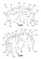
- FIG. 1Ais a side elevation view of an arcuate fixation member constructed in accordance with an embodiment
- FIG. 1Bis a perspective view of the arcuate fixation member illustrated in FIG. 1A ;
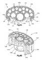
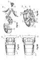
- FIG. 2Ais a top elevation view of an intervertebral implant spacer for use with arcuate fixation members, constructed in accordance with an embodiment
- FIG. 2Bis a front elevation view of the intervertebral implant spacer illustrated in FIG. 2A ;
- FIG. 2Cis a side elevation view of the intervertebral implant spacer illustrated in FIG. 2A ;
- FIG. 3Ais a front elevation view of an insert plate for use with the intervertebral implant spacer illustrated in FIGS. 2A-C ;
- FIG. 3Bis a top elevation view of the insert plate illustrated in FIG. 3A ;
- FIG. 4Ais a front elevation view of a blocking plate for use with the insert plate illustrated in FIGS. 3A-B ;
- FIG. 4Bis a top elevation view of the blocking plate illustrated in FIG. 4A ;
- FIG. 4Cis a front elevation view of a blocking plate similar to the blocking plate illustrated in FIG. 4A , but constructed in accordance with an alternative embodiment
- FIG. 5is a side elevation view of a locking screw for use with the insert plate and blocking plate illustrated in FIGS. 3A-B and 4 A-B, respectively;
- FIG. 6Ais an exploded view of an intervertebral implant assembly constructed from the intervertebral implant system components illustrated in FIGS. 1A-5 ;
- FIG. 6Bis a perspective view of the intervertebral implant assembly illustrated in FIG. 6A , in an assembled configuration
- FIG. 6Cis a side elevation view of the intervertebral implant assembly illustrated in FIG. 6B , inserted into an intervertebral space;
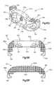
- FIG. 7Ais a side elevation view of an arcuate fixation member constructed in accordance with an alternative embodiment
- FIG. 7Bis a front perspective view of the arcuate fixation member illustrated in FIG. 7A ;
- FIG. 7Cis a rear elevation view of the arcuate fixation member illustrated in FIG. 7A ;
- FIG. 7Dis a rear perspective view of the arcuate fixation member illustrated in FIG. 7A ;
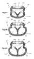
- FIG. 7Eis a front perspective view of a portion of the arcuate fixation member in FIG. 7A , showing a guidance member;
- FIG. 7Fis a rear perspective view of the portion of the arcuate fixation member in FIG. 7E ;
- FIG. 7Gis a top elevation view of the arcuate fixation member illustrated in FIG. 7A ;
- FIG. 7His a sectional front elevation view of the arcuate fixation member illustrated in FIG. 7G , taken along line 7 H- 7 H;
- FIG. 7Iis a rear elevation view of an arcuate fixation member similar to the arcuate fixation member illustrated in FIG. 7A , but constructed in accordance with an alternative embodiment;
- FIG. 7Jis a rear perspective view of the arcuate fixation member illustrated in FIG. 7I ;
- FIG. 8Ais a top elevation view of an intervertebral implant spacer for use with arcuate fixation members, constructed in accordance with an alternative embodiment
- FIG. 8Bis a perspective view of the intervertebral implant spacer illustrated in FIG. 8A ;
- FIG. 8Cis a front elevation view of the intervertebral implant spacer illustrated in FIG. 8A ;
- FIG. 8Dis a side elevation view of the intervertebral implant spacer illustrated in FIG. 8A ;
- FIG. 9Ais a top elevation view of an intervertebral implant spacer for use with arcuate fixation members, constructed in accordance with another alternative embodiment
- FIG. 9Bis a perspective view of the intervertebral implant spacer illustrated in FIG. 9A ;
- FIG. 9Cis a front elevation view of the intervertebral implant spacer illustrated in FIG. 9A ;
- FIG. 9Dis a side elevation view of the intervertebral implant spacer illustrated in FIG. 9A ;
- FIG. 10Ais a top elevation view of an insert plate for use with the intervertebral implant spacers illustrated in FIGS. 8A-D and 9 A-D;
- FIG. 10Bis a front elevation view of the insert plate illustrated in FIG. 10A ;
- FIG. 10Cis a rear elevation view of the insert plate illustrated in FIG. 10A ;
- FIG. 10Dis a perspective view of the insert plate illustrated in FIG. 10A ;
- FIG. 10Eis a top elevation view of the insert plate illustrated in FIG. 10A , constructed in accordance with an alternative embodiment
- FIG. 10Fis a top elevation view of the insert plate illustrated in FIG. 10A , constructed in accordance with another alternative embodiment
- FIG. 11Ais a top elevation view of an intervertebral implant constructed with an alternative embodiment of the intervertebral implant spacer illustrated in FIGS. 8A-D and the insert plate illustrated in FIGS. 10A-D ;
- FIG. 11Bis a sectional elevation view of the intervertebral implant illustrated in FIG. 11A , taken along line 11 B- 11 B;
- FIG. 12Ais a top elevation view of the intervertebral implant illustrated in FIG. 11A , constructed in accordance with an alternative embodiment
- FIG. 12Bis a top elevation view of the intervertebral implant illustrated in FIG. 11A , constructed in accordance with another alternative embodiment;
- FIG. 12Cis a top elevation view of the intervertebral implant illustrated in FIG. 11A , constructed in accordance with still another alternative embodiment;
- FIG. 13Ais a side elevation view of an intervertebral implant constructed in accordance with an embodiment.
- FIG. 13Bis a side elevation view of the intervertebral implant illustrated in FIG. 12A , constructed in accordance with another embodiment.
- FIG. 14Ais an exploded view of an intervertebral implant constructed from the intervertebral implant system components illustrated in FIGS. 7A-8D and 10A -D;
- FIG. 14Bis a perspective view of the intervertebral implant illustrated in FIG. 14A , in an assembled configuration.
- arcuate and curvedrefer generally to the varying physical geometry of an object along an axis coincident to the object, for example the deviation from straightness of the body of an arcuate fixation member along a central longitudinal axis defined within the body of the object between its proximal and distal ends.
- a straight axis projected from a first end of such an objectas distance from the first end of the object increases along the central longitudinal axis of the object, distance between the central longitudinal axis of the object and the straight axis increases more or less continuously, so that the body of the object defined along its central longitudinal axis takes on a curved or arcuate shape.
- the resulting curvature of the central longitudinal axismay exhibit a constant or uniform radius with respect to a point in space defined remotely from the body of the object. Alternatively, a non-uniform or varying radius of curvature may be defined.
- the curvature of the body of the object defined by the longitudinal axismay also vary in direction with respect to a Cartesian coordinate system. The curvature may be uniformly distributed along the body of the object, for example between the proximal and distal ends of the object, or may be localized within one or more distinct segments of the body of the object.
- the curvature of the objectmay be significantly smooth and continuous along its central longitudinal axis, may be defined by a series of straight interconnected segments where each successive segment defines an increasing angle between the central longitudinal axis of the body of the object and the straight axis, or any combination thereof.
- vertebral bodyas used herein should be interpreted broadly to include all the bones and bony structures found within and in the immediate proximity of the human spinal system, including but not limited to those found in the cervical region, the thoracic region, the lumbar region, and the sacral curve region.
- an intervertebral implant system 100comprising a bone fixation member which can define an arcuate fixation member 12 C as illustrated, an intervertebral implant spacer 108 , an insert plate 116 , a blocking plate 132 , and a locking screw 138 are illustrated.
- Applications of the intervertebral implant system 100could include, but are not limited to, fixation of the endplate components of a total disc replacement to vertebral bodies, direct fixation of an intervertebral implant to vertebral bodies, fixation into osteoporotic bone, and the like.
- arcuate fixation membersare particularly suitable when a linear line-of-approach for delivering a fixation member is undesirable. It should be noted that the physical characteristics of the arcuate fixation members disclosed herein may cause them to be alternately described as curved fixation members, arcuate or curved blades, arcuate or curved pins, arcuate or curved nails, or other terms of similar descriptive import.
- fixation members 12 Cmay be utilized to securely anchor an assembled configuration of intervertebral implant system 100 within an intervertebral space between adjacent vertebral bodies.
- the intervertebral implant system 100 and its componentscan be manufactured from any suitable biocompatible material known in the art including but not limited to titanium, titanium alloy such as TAN, commercially pure titanium, stainless steel, tantalum, polymers such as polyether ether ketone (PEEK), reinforced plastics, allograft bone, and the like.
- the arcuate fixation member 12 Cincludes a body 102 defining a proximal end 102 a and a distal end 102 b opposite the proximal end.
- the distal end 102 bmay comprise a tip 104 configured to cut into underlying structure or bone.
- the body 102may further define an intermediate portion between the proximal end 102 a and the distal end 102 b that is curved along a central curved axis L1.
- the intermediate portionis curved along substantially the entire length of the body 102 between the proximal end 102 a and the distal end 102 b .
- one or more distinct portions of the intermediate portion between the proximal end 102 a and the distal end 102 bmay be curved (not shown).
- the intermediate portionis curved along the central curved axis L1 in accordance with a uniform radius of curvature R1.
- the intermediate portionmay define a non-uniform radius of curvature along the central curved axis L1.
- the curvature of the intermediate portionmay be smooth and continuous.
- the curvature of the intermediate portionmay be defined by a series of substantially straight sections (not shown), with each substantially straight section aligned along an individual longitudinal axis corresponding to the individual section, where the magnitude of an angle ⁇ with respect to a perpendicular reference axis extended from the proximal end 102 a increases in magnitude with the distance of each subsequent straight section from the proximal end 102 a.
- the arcuate fixation member 12 Cmay have a head 106 defined at the proximal end 102 a of the body 102 .
- the head 106may extend radially outward from the proximal end 102 a of the body 102 in a direction perpendicular to the longitudinal axis L1.
- the head 106may extend from the body 102 in a direction generally opposite from the direction of curvature of the body 102 , as depicted in FIGS. 1A-B .
- the head 106may extend from the body 102 in a direction generally towards the direction of curvature of the body 102 .
- the headmay define an upper surface 106 a configured for multi-angular engagement with a complementary surface of a delivery instrument, and a lower surface 106 b opposite the upper surface 106 a and configured to engage another component of the intervertebral implant system 100 , for example the insert plate 116 , when the arcuate fixation member 12 C is in a fully inserted position.
- the intervertebral implant spacer, or spacer 108is defined by a posterior side 108 a , an anterior side 108 b opposite the posterior side, lateral sides 108 c , an upper surface 108 d , and a lower surface 108 e opposite the upper surface.
- a portion of the posterior side 108 a between the lateral sides 108 cmay be curved inwardly in the direction of the anterior side 108 b , defining a rounded, generally rectangular kidney-like footprint, as depicted in FIG. 2A .
- a portion of the posterior side 108 a between the lateral sides 108 cmay be curved outwardly in a direction away from the anterior side 108 b (not shown).
- the posterior side 108 amay be substantially straight between the lateral sides 108 c , defining a rounded, generally rectangular footprint (not shown).
- the spacer 108may have a central bore 110 defined therethrough, the shape of which substantially conforms to the footprint of the spacer 108 (e.g., a rounded, generally rectangular kidney-like footprint, or a rounded, generally rectangular footprint, depending upon the geometry of the posterior side 108 a ).
- the central bore 110can be filled with bone growth inducing substances to allow bony ingrowth and to assist in fusion between the spacer 108 and adjacent vertebral bodies.
- the upper and lower surfaces 108 d and 108 emay have gripping structures 108 h such as teeth, spikes, or similar structures, defined thereon and configured to facilitate gripping engagement between the upper and lower surfaces 108 d and 108 e and the end plates of adjacent vertebral bodies.
- the teeth 112may be pyramidal, saw toothed or other similar shapes.
- portions of and/or the entirety of the upper and lower surfaces 108 d and 108 emay be substantially smooth and devoid of any protrusions.
- Upper and lower edges 108 f and 108 gdefined where the upper and lower surfaces 108 d and 108 e intersect with the posterior, anterior, and lateral sides 108 a , 108 b , and 108 c respectively around the outer perimeter of the spacer 108 , may be rounded (not shown).
- the upper and lower edges 108 f and 108 gmay be rounded using a uniform radius of curvature around the perimeter of the implant.
- the upper and lower edges 108 f and 108 gmay be rounded using a non-uniform radius of curvature around the perimeter of the implant.
- the upper and lower edges 108 f and 108 g along the anterior side 108 bmay be rounded with a greater radius than the remainder of the upper and lower edges 108 f and 108 g , such that a bull nose outer surface (not shown) is created on the anterior side 108 b of the implant. Rounding upper and lower edges 108 f and 108 g may facilitate easier insertion of the spacer 108 , for example by minimizing required distraction of the end plates of adjacent vertebral bodies.
- the spacer 108has a generally wedge-shaped side-view profile. As illustrated in FIG. 2C , this wedge shape is defined by a gradual decrease in the height of the spacer 108 (as measured between the upper and lower surfaces 108 d and 108 e ) extending between the posterior side 108 a in the direction of the anterior side 108 b .
- the spacer 108has a generally constant height between lateral sides 108 c .
- the spacer 108may have a gradual increase in height followed by a gradual decrease in height extending from one lateral side 108 c to the other, and/or may have a generally constant height between the posterior and anterior sides 108 a and 108 b , or may have convex and/or concave upper and lower surfaces 108 d and 108 e , thereby defining a gradual increase in height followed by a gradual decrease in height extending from the posterior side 108 a to the anterior side 108 b and from one lateral side 108 c to the other.
- a plurality of grooves 112may be defined on the spacer 108 where the upper and lower surfaces 108 d and 108 e intersect with the anterior side 108 b .
- the grooves 112may be concave and may be configured to align with arcuate grooves 128 of the insert plate 116 when the spacer 108 and the insert plate 116 are in an assembled configuration.
- the grooves 112may be substantially smooth and devoid of any protrusions.
- Retaining grooves 114may be defined within the lateral sides 108 c of the spacer 108 between the upper and lower surfaces 108 d and 108 e .
- the retaining grooves 114may be configured to releasably engage complementary engaging ribs 120 of the insert plate 116 .
- the fixation plate, or insert plate, or insert 116is defined by a generally C-shaped, channel-like body 118 that includes an anterior side 118 a with upper and lower sides 118 b and 118 c opposite each other, and lateral sides 118 d extending from opposite sides of the anterior side 118 a in a generally perpendicular direction from the anterior side 118 a .
- the anterior, upper, lower, and lateral sides 118 a , 118 b , 118 c , and 118 dmay form a generally channel-like structure (in essence, a cradle) which may be configured to receive the anterior side 108 b and at least a portion of the lateral sides 108 c in partial nested engagement.
- the upper and lower sides 108 b and 108 cmay define gradual increases and/or decreases in height in a posterior direction from the anterior side 118 a and/or between the lateral sides 108 d , in order to generally conform the insert plate 116 to the geometry of the spacer 108 .
- the lateral sides 118 dmay have engaging ribs 120 defined thereon at the ends opposite the anterior side 118 a , the engaging ribs 120 configured to be releasably received within the retaining grooves 114 of the spacer 108 .
- the anterior side 118 a of the insert plate 116may have a pair of apertures 122 defined therethrough configured to receive grasping members of a delivery instrument.
- the apertures 122may be D-shaped, as illustrated in FIG. 3A .
- any other aperture shapemay be defined as appropriate.
- the apertures 122may have a retaining rib 124 defined therein configured to engage with a complementary grasping rib of the delivery instrument.
- the anterior side 118 a of the insert plate 116may also have a central bore 126 defined therethrough having an inner surface 126 a with threads configured to engage complementary threads of a locking screw 138 .
- the anterior side 118 a of the insert plate 116may also have a concave recess 130 defined therein configured to receive a complementary convex surface 134 d of the blocking plate 132 .
- the anterior side 118 a of the insert plate 116may also have a plurality of arcuate grooves 128 defined therethrough configured to slidably receive the arcuate fixation members 12 C and to define an insertion trajectory for each of the arcuate fixation members 12 C.
- the arcuate grooves 128may have a generally uniform cross sectional geometry configured to closely conform to the cross sectional geometry of the body 102 of the arcuate fixation member 12 C between the head 106 and the distal end 102 b .
- the arcuate grooves 128have a recessed ledge defined therein in the area where the arcuate grooves 128 intersect with the outer surface of the anterior side 118 a of the insert plate 116 , the recessed ledge being configured to receive the lower surface 106 b of the head 106 when the arcuate fixation member 12 C is in a fully inserted position, such that the upper surface 106 a of the head 106 is substantially flush with the outer surface of the anterior side 118 a of the insert plate 116 .
- the arcuate grooves 128may be disposed about the central bore 126 in any desired configuration and may define any insertion trajectories as appropriate.
- the arcuate grooves 128are defined in opposing quadrants around the central bore 126 , with two arcuate grooves 128 located near the upper side 118 b and defining two generally cranial insertion trajectories, and two arcuate grooves 128 located near the lower side 118 c and defining two generally caudal insertion trajectories. It should be noted that this configuration of arcuate groove 128 locations and arcuate fixation member 12 C insertion trajectories is merely an example, and the scope of the instant disclosure should not be limited thereto.
- the blocking plate 132is defined by a generally disc-shaped body 134 with upper and lower surfaces 134 a and 134 b that can be planar as illustrated, an anterior surface 134 c , and a posterior surface 134 d .
- the disc-shaped body 134can further define opposed side surfaces 135 a and 135 b , which can be convexly curved, extending between the upper and lower surfaces 134 a - b .
- the upper and lower surfaces 134 a and 134 b and the height of the body 134may be defined to match the height (as measured between the upper and lower surfaces 134 b and 118 c ) of the anterior side 118 a of the insert plate 116 when the blocking plate 132 is in a fully assembled configuration.
- the anterior surface 134 c of the body 134may be generally planar, or may be defined to match the outer surface of the anterior side 118 a of the insert plate 116 when the blocking plate 132 is in a fully assembled configuration.
- the posterior surface 134 dmay be defined as a convex surface configured to engage with the concave recess 130 of the insert plate 116 when the blocking plate 132 is in a fully assembled configuration.
- the posterior surface 134 dcan also be configured to engage the heads 106 of the arcuate fixation members 12 C inserted into the arcuate grooves 128 of the insert plate 116 .
- the posterior surface 134 dcan operate to drive the arcuate fixation members 12 C into a fully inserted position within the insert plate 116 as the locking screw 138 is tightened.
- the blocking plate 138can additionally prevent backout of the arcuate fixation members 12 C.
- the posterior surface 134 d of the blocking plate 132is not limited to the illustrated convex surface, and that the posterior surface 134 d can define alternative geometries.
- the posterior surface 134 dmay define a plurality of angled surfaces, such as four angled surfaces in opposed quadrants of the posterior surface 134 d , each of the angled surfaces configured to engage with the head 106 of a corresponding arcuate fixation member 12 C.
- the body 134may have an aperture 136 defined therethrough.
- the diameter of the aperture 136may be slightly larger than the diameter of the central bore 126 of the insert plate 116 , such that a locking screw 138 may be inserted into the aperture 136 with no interference therebetween.
- the diameter of the aperture 136may be substantially the same as that of the central bore 126 , and the inner surface of the aperture 136 may have threads defined thereon, the threads configured to engage complementary threads of the locking screw 138 .
- the aperture 136may further be defined by a concave recess 136 a defined within the anterior surface 134 c , the concave recess 136 a configured to receive the convex head 142 of the locking screw 138 .
- the blocking plate 132can be geometrically configured as desired so as to be received and nest in the concave recess 362 and coupled to the insert plate 350 .
- the upper and lower surfaces 134 a - b of the disc-shaped body 134can be curved, and bow outwards in accordance with one embodiment.
- the side surfaces 135 a - bcan extend substantially straight between the upper and lower surfaces 134 a - b .
- the disc-shaped body 134can further define beveled surfaces 137 a - d that are connected between respective side surfaces 135 a and 135 b and respective upper and lower surfaces 134 a and 134 b .
- Pockets 139 a - bcan be defined extending into the side surfaces 135 a - b , the pockets 139 a - b configured to receive a driving instrument that braces against the blocking plate 132 so as to drive the locking screw 138 into the insert plate 350 .
- the locking screw 138includes a shaft 140 that defines longitudinally opposing proximal and distal ends 140 a and 140 b , respectively, and a head 142 coupled to the proximal end 140 a of the shaft 140 , either directly or indirectly via an unthreaded neck 144 that is coupled between the proximal end 140 a of the shaft 140 and the head 142 .
- the head 142can define a generally convex shape between the interface of the head 142 and the neck 144 that extends outward towards a proximal end 142 a of the head 142 .
- the convex shape of the headmay be configured to engage the concave recess 136 a of the blocking plate 132 .
- the head 142can assume any other suitable alternative shape as appropriate.
- Helical threads 146extend radially out from the shaft 140 at locations at and between the proximal and distal ends 140 a and 140 b that are configured to engage complementary threads on the inner surface 126 a of the central bore 126 of the insert plate 116 .
- a substantial entirety of the shaft 140 between the proximal and distal ends 140 a and 140 bmay be threaded.
- the distal end 142 a of the head 142may have driving members 142 b defined therein, designed to engage with complementary driving members of a delivery instrument.
- the locking screw 138can alternatively be provided in combination with the blocking plate 132 as a captive locking screw, wherein the locking screw 138 is rotatably retained within the aperture 136 of the blocking plate 132 . It should be appreciated that the head 142 can be externally threaded.
- FIGS. 6A-Can example embodiment of the intervertebral implant system 100 is illustrated in an exploded view and in a nearly completely assembled configuration.
- FIG. 6Bdepicts the intervertebral implant system 100 partially assembled outside of an intervertebral space (the blocking plate 132 and locking screw 138 have been omitted for simplicity).
- the spacer 108has been seated within the insert plate 116 such that the retaining ribs are seated with the retaining grooves 114 on the lateral sides of the spacer 108 .
- Four arcuate fixation members 12 Chave been inserted through corresponding arcuate grooves 128 within the insert plate 116 , and have been driven to an almost fully inserted position.
- the arcuate fixation members 12 CIn a final assembled configuration, the arcuate fixation members 12 C would be driven into their fully inserted position, the blocking plate 132 would be received within the concave recess 130 in the anterior side of the insert plate 116 , and the locking screw 138 would be driven into the central bore 126 of the insert plate 116 and finally tightened, thereby blocking the arcuate fixation members 12 C from backing out of the assembled intervertebral implant system 100 .
- FIG. 6Cdepicts an example embodiment of the intervertebral implant system 100 partially assembled inside of an intervertebral space between adjacent vertebral bodies V6 and V7 (the blocking plate and locking screw have been omitted for simplicity).
- the spacer 108has been prepared for insertion, for example by being packed a with bone growth inducing substance and or/having its outer surfaces properly prepared, and has been seated within the insert plate 116 such the retaining ribs are seated with the retaining grooves on the lateral sides of the spacer 108 .
- the spacer 108was then inserted into the intervertebral space between the adjacent vertebral bodies V6 and V7 using a delivery instrument (not shown).
- the delivery instrumentwas then used to deliver the four arcuate fixation members 12 C into the arcuate grooves in the fixation plate 116 and drive them into an almost fully inserted position.
- the delivery instrumentwould be used to drive the arcuate fixation members 12 C into their fully inserted position, the blocking plate would be received within the concave recess in the anterior side of the insert plate 116 , and the locking screw would be driven into the central bore of the insert plate 116 and finally tightened, thereby blocking the arcuate fixation members 12 C from backing out of the assembled intervertebral implant system 100 .
- FIGS. 7A-14Balternative example embodiments of components of the intervertebral implant system 100 , for instance arcuate fixation member 12 D, intervertebral implant spacers 316 and 336 , and insert plate 350 , are illustrated.
- Various embodiments of an intervertebral implant 400can be constructed from the components of the intervertebral implant system 100 , as described in more detail below.
- the figures and subsequent description pertaining to the arcuate fixation member 12 Ddo not refer to certain features and/or uses of the arcuate fixation member 12 C that may be integrated into the arcuate fixation member 12 D, for example the use of the arcuate fixation member 12 C in combination with above-described components of the intervertebral implant system 100 , for instance the intervertebral implant spacer 108 , the insert plate 116 , the blocking plate 132 , or the locking screw 138 .
- embodiments in which those and other features of the arcuate fixation member 12 C are integrated into the arcuate fixation member 12 Dare intended to be within the scope of the instant disclosure.
- the arcuate fixation member 12 Dincludes a fixation body, or body 300 defining a proximal end 300 a , a distal end 300 b opposite the proximal end, and an intermediate portion 300 c extending between the proximal and distal ends 300 a - b , respectively.
- the fixation body 300has a cross sectional geometry that is substantially hexagonal, defining opposing laterally convex front and rear surfaces 300 e - f extending between opposing sides, or edges 300 d .
- the fixation body 300defines a cross sectional geometry that is substantially constant throughout the intermediate portion 300 c of the fixation body 300 , and is tapered between lateral surfaces 301 converging along the edges 300 d near the distal end 300 b , defining a tip 302 configured to cut into an underlying structure, such as bone.
- the intermediate portion 300 c of the fixation body 300is curved along a central curved axis L1. It should be appreciated that the central curved axis L1 can define an insertion trajectory of the arcuate fixation member 12 D into underlying structure, such as a vertebral body. It should be appreciated that the insertion trajectory can be differently defined, for example in accordance with alternative geometries of the arcuate fixation member 12 D.
- the intermediate portion 300 cis curved along substantially the entire length of the fixation body 300 between the proximal and distal ends 300 a - b , respectively.
- one or more distinct portions of the intermediate portion 300 ccan be curved (not shown).
- the intermediate portion 300 cis curved along the central curved axis L1 in accordance with a uniform radius of curvature R1.
- the intermediate portion 300 ccan define a non-uniform radius of curvature along the central curved axis L1.
- the curvature of the intermediate portion 300 cmay be smooth and continuous.
- the curvature of the intermediate portion 300 ccan be defined by a series of substantially straight sections (not shown), with each substantially straight section aligned along an individual longitudinal axis corresponding to the respective individual section, where the magnitude of an angle ⁇ with respect to a perpendicular reference axis A extended from the proximal end 300 a increases in magnitude with the distance of each subsequent straight section from the proximal end 300 a .
- the cross sectional geometry of the fixation body 300is not limited to the illustrated substantially hexagonal shape, and that the fixation body 300 can alternatively be defined with any suitable cross sectional geometry. It should further be appreciated that the cross sectional dimension of the fixation body 300 may vary, for example increasing or decreasing, throughout one or more portions of the intermediate portion 300 c.
- the arcuate fixation member 12 Dmay have a head 304 defined at the proximal end 300 a of the fixation body 300 .
- the head 304may extend radially outward from the proximal end 300 a of the fixation body 300 in a direction perpendicular to the central curved axis L1.
- the head 304may extend from the fixation body 300 in a direction generally towards the direction of curvature of the fixation body 300 , as depicted in FIGS. 7A-D .
- the head 304may extend from the fixation body 300 in a direction generally opposite from the direction of curvature of the fixation body 300 .
- the head 304may define an upper surface 304 a configured for multi-angular engagement with a complementary surface of a delivery instrument, and a lower surface 304 b opposite the upper surface 304 a and configured to engage another component of the intervertebral implant system 100 , for example the insert plate 350 , when the arcuate fixation member 12 D is in an inserted position.
- the head 304can have one or more tapered surfaces, for instance surface 304 c , defined thereon, the tapered surface 304 c configured to engage with a complementary surface in another component of the intervertebral implant system 100 , for example the insert plate 350 , thereby locking the arcuate fixation member 12 D in an inserted position.
- the fixation body 300can define one or more guidance members, the guidance members configured to guide the tip 302 along an insertion trajectory as the arcuate fixation member 12 D is inserted into an underlying structure, such as a vertebral body.
- guidance membersare disposed at distal end 300 b of the fixation body 300 , and in particular near the tip 302 , but can alternatively be defined at any location on the fixation body 300 .
- the fixation body 300can define guidance members that are recessed within the fixation body 300 , such as the illustrated flutes 306 , or guidance members that comprise projections extending from the fixation body 300 , such as the illustrated outer wings 303 and/or the keel 308 , in any combination.
- a pair of recessed guidance flutes, or flutes 306are defined by a keel 308 disposed between opposing wings 303 .
- the illustrated flutes 306are defined by and are disposed at the tip 302 of the fixation body 300 , the flutes 306 extending into the fixation body 300 from the tip 302 along directions substantially parallel to each other and to the insertion trajectory of the arcuate fixation member 12 D, and terminating in the intermediate section 300 c of the fixation body 300 proximal from the tip 302 .
- the flutes 306can extend along directions that are angularly offset or otherwise non-parallel with respect to each other and/or with respect to the insertion trajectory.
- the flutes 306are not limited to the illustrated length, and can alternatively be defined to terminate within the tip 302 of the fixation body, or to extend along any length, up to the entirety, of the fixation body 300 . It should be appreciated that the flutes 306 can be symmetrically with respect to each other as illustrated, or asymmetrically. For example the flutes 306 can be defined with matching or different geometries, equal or different lengths, equal or different depths, etc.
- the illustrated flutes 306have a substantially “V” shaped geometry defined by outer wings, or wings 303 defined in the fixation body 300 and inner surfaces, or keel surfaces 305 defined in the fixation body 300 , the wings 303 and keel surfaces 305 converging in troughs 307 .
- the keel surfaces 305define a keel 308 , as described in more detail below, the flutes 306 are disposed between respective wings 303 and the keel 308 .
- the wings 303are not limited to the illustrated offset wings 303 disposed adjacent the keel 308 on respective sides of the keel 308 , and that a single, up to a plurality of wings 303 can be defined at any location in the fixation body 300 , for example substantially centrally between the edges 300 d , offset laterally toward either edge 300 d , or substantially along either edge 300 d .
- the wings 303 and/or the keel surfaces 305are not limited to being defined within the cross sectional geometry of the fixation body 300 , and can alternatively be defined to extend outwardly from the fixation body 300 , for example from the front or rear surfaces 300 e - f and/or the edges 300 d .
- the geometries of the flutes 306are not limited to the illustrated “V” shape, and can alternatively be defined with any suitable geometry.
- the keel surfaces 305define a projection from the fixation body 300 , the projection configured as a guidance member in the form of a guidance keel, or keel 308 .
- the keel 308is defined substantially centrally between the edges 300 d of the fixation body 300 , and disposed between the wings 303 .
- the keel 308can be laterally offset toward either edge 300 d .
- the arcuate fixation member 12 Dis not limited to a single keel 308 as illustrated, and that the fixation body 300 can define a plurality of keels 308 at any locations in the fixation body 300 .
- arcuate fixation member 12 Dis not limited to the illustrated configuration of guidance members, and that the fixation body 300 can be differently constructed with any number of wings 303 , flutes 306 , keels 308 , or any other guidance members, in any combination.
- the fixation body 300 of the arcuate fixation member 12 Dcan define one or more gripping structures configured to be retain the arcuate fixation member 12 D in an inserted position within an underlying structure, such as a vertebral body.
- the gripping structurescan include protrusions defined on the fixation body 300 , such as teeth, spikes, or similar structures.
- a plurality of teeth 310are defined in rows on opposing sides of the fixation body 300 , in particular in the intermediate portion 300 c of the fixation body 300 along the edges 300 d .
- the illustrated plurality of teeth 310are defined by a corresponding plurality of substantially “V” shaped notches 312 defined along the edges 300 d of the fixation body 300 .
- the notches 312are defined in parallel directions with respect to each other, such that the magnitude of an angle ⁇ between each notch 312 and the perpendicular reference axis A is maintained.
- the notches 312can be defined in directions that are not parallel with respect to each other, for example such that the magnitude of the angle ⁇ increases with the distance of each successive notch 312 from the proximal end 300 a of the fixation body 300 .
- the gripping structuresare not limited to being defined along the edges 300 d of the fixation body 300 , and that gripping structures supplemental to, or in lieu of, the illustrated teeth 310 can alternatively be defined in any other suitable location on the fixation body 300 . It should further be appreciated that the gripping structures are not limited to the gripping structure geometry of the illustrated teeth 310 , and that the fixation body 300 can alternatively define any other suitable gripping structure geometry. It should further still be appreciated that the number and/or geometry of the gripping structures can be defined so to add bone growth surface area to the arcuate fixation member 12 D.
- One or more removal memberscan be defined in the fixation body 300 of the arcuate fixation member 12 D, the removal members allowing for distraction of the arcuate fixation member 12 D from an underlying structure, such as a vertebral body.
- a pair of grooves 314are defined at the proximal end 300 a of the fixation body 300 , the grooves 314 extending into the fixation body 300 from the edges 300 d .
- the illustrated grooves 314are sized to receive complementary members of a removal tool.
- FIGS. 7A-Ha pair of grooves 314 are defined at the proximal end 300 a of the fixation body 300 , the grooves 314 extending into the fixation body 300 from the edges 300 d .
- the illustrated grooves 314are sized to receive complementary members of a removal tool.
- a single groove 314is defined at the proximal end 300 a of the fixation body 300 , the groove 314 extending into the rear surface 300 f .
- the arcuate fixation member 12 Dis not limited to the illustrated removal members, and that the fixation body 300 can be alternatively be defined with one or more other suitable removal members.
- the intervertebral implant spacer, or spacer 316defines a spacer body, or body 318 configured to be implanted into an intervertebral space, the spacer body 318 having an outer wall 318 c that defines an enclosed perimeter of the spacer body 318 .
- the outer wall 318 ccomprises an anterior wall 318 a extending between opposing ends 318 b , a posterior wall 318 d opposite the anterior wall 318 a , and opposing side walls 318 e , the side walls 318 e extending between the ends 318 b of the anterior wall 318 a and the posterior wall 318 d .
- the spacer body 318defines an upper surface 318 f , and a lower surface 318 g opposite the upper surface.
- the outer wall 318 cdefines an aperture 322 extending into the spacer body 318 through at least one of the upper or lower surfaces 318 f - g.
- a portion, up to an entirety of the anterior wall 318 acan be curved inwardly toward the posterior wall 318 d , defining an apex of curvature, or apex 320 in the anterior wall 318 a approximately midway between the opposing ends 318 b , as depicted in FIGS. 8A-B .
- the apex 320can be defined at any other location along the anterior wall 318 a .
- the anterior wall 318 acan be straight between the ends 318 b , can be curved outwardly away from the posterior wall 318 d , or can define one or more distinct straight portions and/or curved portions between the ends 318 b , thereby defining a corresponding number of apices 320 along the anterior wall 318 a .
- shape of the perimeter of the spacer body 318is not limited to the illustrated geometry, and that the outer wall 318 c can be differently constructed to define an alternatively shaped perimeter geometry of the spacer body 318 .
- the spacer body 318can further include an inner wall 318 h , the inner wall 318 h defined so as to divide the aperture 322 defined by the outer wall 318 c into a plurality of apertures 322 .
- the inner wall 318 hdivides the aperture 322 defined by the outer wall 318 c into a pair of apertures 322 .
- the illustrated inner wall 318 hextends between the apex 320 of the anterior wall 318 a and the outer wall 318 c , in particular between the apex 320 and substantially the midpoint of the posterior wall 318 d .
- At least one additional aperture 322can be defined between the anterior wall 318 a and an insert plate, such as insert plate 350 (See FIGS.
- One or more of the plurality of apertures 322can be filled with bone growth inducing substances, for example to allow bony growth ingress and/or egress with respect to the spacer 316 and to assist in fusion between the spacer 316 and adjacent vertebral bodies.
- the spacer body 318can be differently constructed, thereby alternatively defining the plurality of apertures 322 .
- the inner wall 318 hcan alternatively be defined to extend between any respective locations on the anterior wall 318 a and the outer wall 318 c .
- the spacer body 318is not limited to a single inner wall 318 h as illustrated, and that alternatively a plurality of inner walls 318 h having any combination of straight or curved geometries can be defined, the inner walls 318 h of the plurality of inner walls 318 h extending between a single or multiple locations on the anterior wall 318 a and a single or multiple corresponding locations on the outer wall 318 c , extending between respective locations on one or more inner walls 318 h and the outer wall 318 c , extending between a single or multiple locations on the outer wall 318 c , extending from a single or multiple locations on the anterior wall 318 a in a generally outward direction away from the posterior wall 318 d , or any combination thereof. It should further still be appreciated that the respective thicknesses of the anterior wall 318 a , the outer wall 318 c , and/or the inner wall 318 h can be uniform, or can have one or more portions of varying thickness.
- One or more portions, up to an entirety of surfaces of the spacer body 318can be configured to allow bony ingrowth into the respective surfaces by bone growth inducing substances disposed into the apertures 322 , for instance to enhance fusion between the spacer 316 and adjacent vertebral bodies and/or to provide a form of secondary fixation between an intervertebral implant 400 constructed with the spacer 316 and adjacent vertebral bodies.
- one or more portions of the inner surface 318 c ′ of the outer wall 318 ccan be recessed, defining respective cavities 324 therein.
- the cavities 324can be open to respective apertures 322 , such that the cavities 324 can be filled with bone growth inducing substances and/or to allow the above-described bony ingrowth into the cavities 324 .
- the spacer body 318is not limited to the illustrated cavities 324 , and that the surfaces of the spacer body 318 can be differently constructed with any other geometries in order to allow body ingrowth.
- the apertures 322 defined in the spacer body 318can be configured to be in communication with each other, for example to facilitate biological communication between bone growth inducing substances in respective apertures 322 and/or to allow bony growth ingress and/or egress between the apertures 322 .
- one or more openings, such as openings 326can be defined through the outer wall 318 c and/or the inner wall 318 h , the openings 326 placing two or more of the plurality of apertures 322 in communication with each other.
- a pair of openings 326are defined through the outer wall 318 c , and in particular the anterior wall 318 a .
- the spacer body 318can alternatively configured to define one, up to a plurality of openings 326 through the outer wall 318 c and/or the inner wall 318 h at any locations along the outer wall 318 c and/or the inner wall 318 h.
- the spacer 316is configured to be coupled to an insert plate, such as insert plate 350 .
- Coupling memberscan be defined on the spacer body 318 , the coupling members configured to releasably mate with complementary coupling members of an insert plate.
- coupling members in the form of retaining grooves 328are defined in the ends 318 b of the anterior wall 318 a , the retaining grooves 328 extending into the spacer body 318 from open ends 328 a defined in the lower surface 318 g and terminating in closed ends 328 b near the upper surface 318 f .
- the retaining grooves 328are configured to receive complementary retaining members, such as the retaining members 356 defined on the insert plate 350 , therein.
- the closed ends 328 b of the retaining grooves 328can operate to retain the retaining members 356 of an insert plate within the retaining grooves 328 and/or act as stops to ensure proper alignment between an insert plate and the spacer 316 during assembly.
- the spacer 316can be constructed such that the retaining grooves 328 extend along the entirety of the body 318 , such that both ends 328 a - b are open.
- Interlocking memberscan be defined on the coupling members, the interlocking members configured to be received in releasably locking engagement with complementary interlocking members defined on the retaining members 356 of the insert plate 350 .
- interlocking members in the form of locking ridges 330are defined in the retaining grooves 328 , the locking ridges 330 sized to be received in releasably locking engagement within complementary locking grooves 358 defined on the retaining members 356 of the insert plate 350 .
- the interlocking memberscan be configured to facilitate a desired alignment in the transverse, or cranial-caudal direction between the insert plate and the spacer 316 .
- the illustrated locking ridges 330are located within the retaining grooves 328 at a location approximately equal to the height wise midpoint of the anterior wall 318 a , thereby ensuring that when the retaining members 356 are inserted into the retaining grooves 328 such that the locking ridges 330 are received in the locking grooves 358 (see FIG. 11B ), the spacer 316 and the insert plate will achieve a desired transverse alignment with respect to each other.
- the upper and lower surfaces 318 f - g of the spacer body 318can define a plurality of relief members, such as relief grooves 332 , the relief grooves 332 configured to align with guide apertures 366 of the insert plate 350 (see FIGS. 10A-E ) and to partially receive the fixation bodies 300 of respective arcuate fixation members 12 D therein when an intervertebral implant 400 is assembled from the spacer 316 and an insert plate 350 and one or more arcuate fixation members 12 D are inserted into the guide apertures 366 of the insert plate 350 and driven into position in an underlying structure, such as a vertebral body.
- the relief grooves 332are concave and are substantially smooth and devoid of any protrusions. It should be appreciated that the spacer 316 can be alternatively constructed without the relief grooves 332 .
- the upper and lower surfaces 318 f - g of the spacer body 318can be configured as bone-engaging surfaces, for example by defining gripping structures thereon, such as teeth, spikes, or the like.
- the gripping structurescan be configured to engage adjacent underlying structures, such as the endplates of adjacent vertebral bodies, when the intervertebral implant 400 is inserted into an intervertebral space.
- the upper and lower surfaces 318 f - ghave teeth 334 defined thereon.
- the teeth 334may be pyramidal, saw toothed or other similar shapes.
- portions of, up to the entirety of the upper and/or lower surfaces 318 f - gcan be substantially smooth and devoid of any gripping structures.
- the upper perimeter edge, or upper edge 318 f and the lower perimeter edge, or lower edge 318 g ′ of the spacer body 318 , defined along the outer periphery of the spacer body 318 where the outer surface of the outer wall 318 c intersects with the upper and lower surfaces 318 f - g , respectively,can be rounded. Rounding the upper and lower edges 318 f ′-g′ can facilitate easier insertion and/or removal of the spacer 316 , and thus the intervertebral implant 400 , from an intervertebral space, for example by minimizing required distraction of the end plates of adjacent vertebral bodies.
- Distinct portions, up to an entirety of the upper and lower edges 318 f ′-g′can be rounded using a varying radius of curvature.
- respective portions of the upper and lower edges 318 f ′-g′ along the posterior wall 318 dare rounded with a greater radius of curvature than the remainder of the upper and lower edges 318 f ′-g′, such that a “bullet tip” profile is defined on the posterior wall 318 d of the spacer body 318 , as depicted in FIG. 8D .
- the upper and lower edges 318 f ′-g′can be rounded using a substantially constant radius of curvature.
- the upper and lower surfaces 318 f - gcan be defined as partially, up to fully convex surfaces.
- the convexity of the upper and lower surfaces 318 f - g in the anterior-posterior direction between the anterior wall 318 a and the posterior wall 318 ddiffers from the convexity of the upper and lower surfaces 318 f - g in the lateral direction between the side walls 318 e .
- the upper and lower surfaces 318 f - gare fully convex in the anterior-posterior direction, and exhibit asymmetric convexity with respect to each other, wherein the anterior-posterior convexity of the upper surface 318 f is defined using a shorter radius than the radius used to define the convexity of the lower surface 318 g . In other words, the upper surface 318 f exhibits a greater amount of curvature than the lower surface 318 g .
- the upper and lower surfaces 318 f - gare partially convex in the lateral direction, and exhibit symmetric convexity with respect to each other, wherein the lateral convexities of the upper and lower surfaces 318 f - g are equal, or mirror images of each other.
- the upper and lower surfaces 318 f - gdefine substantially no convexity in the lateral direction throughout the region C2, and are convex in the lateral direction in the regions C1 near the side walls 318 e.
- the geometry of the upper and lower surfaces 318 f - gis not limited to the convexity of the illustrated embodiment, and that the upper and lower surfaces 318 f - g can be defined with full or partial convexity in the anterior-posterior and/or lateral directions, with full or partial concavity in the anterior-posterior and/or lateral directions, with a combination of partial convexity and concavity in the anterior-posterior and/or lateral directions, or with no curvature at all (i.e., substantially flat) in the anterior-posterior and/or lateral directions. It should further be appreciated that the regions C1 and C2 can be defined with wider or narrower widths in the lateral direction. It should further still be appreciated that the geometry of the upper and lower surfaces 318 f - g can be defined either symmetrically or asymmetrically with respect to each other.
- the illustrated embodiment of the spacer 316has a generally wedge shaped side view profile defined by a gradual increase in height followed by a gradual decrease in height between the anterior wall 318 a and the posterior wall 318 d , and a generally rectangular front view profile defined by a generally constant height throughout the C2 region, and gradually decreasing height throughout the C1 regions between the opposing ends of the C2 region and the side walls 318 e .
- the height between the anterior wall 318 a and the posterior wall 318 d of the spacer 316may gradually decrease, may gradually increase, may have a gradual decrease followed by a gradual increase, or may be generally constant, while the height between the side walls 318 e may increase and/or decrease, or may be generally constant.
- the geometry of the spacer 316for instance the geometry of the upper and lower surfaces 318 f - g and/or the difference in the height of the body 318 between the anterior and posterior walls 318 a , 318 d defines a lordotic angle ⁇ of the spacer 316 .
- the lordotic angle ⁇ defined by the spacer 316can be increased and/or decreased by varying the geometry of the spacer 316 .
- the lordotic angle ⁇ defined by the illustrated spacer 316can be increased by heightening the anterior wall 318 a of the spacer 316 while maintaining the height of the posterior wall 318 d .
- the anterior-posterior convexity defined by the upper surface 318 fis increased with increasing magnitude of the lordotic angle ⁇ , while the anterior-posterior convexity defined by the lower surface 318 g is maintained.
- the anterior-posterior convexity and/or the lateral convexity of the upper and/or lower surfaces 318 f - gcan be increased or decreased in any combination such that the upper and lower surfaces 318 f - g are defined the same or differently.
- the intervertebral implant spacer, or spacer 336defines a generally hollow spacer body, or body 338 having an open anterior end 338 a defined between opposing ends 338 b , an outer wall 338 c extending around a perimeter of the spacer body 336 between the ends 338 b , and opposing upper and lower plates 338 f - g , the outer wall 338 c extending between the upper and lower plates 338 f - g .
- the upper and lower plates 338 f - gdefine respective upper and lower surfaces 338 h - i .
- the outer wall 338 cis defined by a posterior wall 338 d opposite the anterior end 338 a and opposing side walls 338 e , the side walls 338 e extending between the ends 338 b and the posterior wall 338 d .
- shape of the perimeter of the spacer body 338is not limited to the illustrated geometry, and that the outer wall 338 c can be differently constructed to define an alternatively shaped perimeter geometry of the spacer body 338 .
- the spacer body 338can have a plurality of openings, such as apertures 340 and/or slots 342 defined therethrough, for example to allow bony growth ingress and/or egress with respect to the spacer body 338 , the bony growth ingress and/or egress assisting in fusion between the spacer 336 and adjacent vertebral bodies and/or providing a form of secondary fixation between an intervertebral implant 400 constructed with the spacer 336 and adjacent vertebral bodies.
- a plurality of apertures 340are defined extending through the upper and lower plates 338 f - g
- a plurality of slots 342are defined extending through the outer wall 338 c .
- the apertures 340 that extend through each of the respective platescan have varying diameters with respect to each other and extend through the plates at locations that define a pattern that can be repeated between the upper and lower plates 338 f - g such that the each of the apertures 340 that extend through the upper plate 338 f are aligned with corresponding apertures that extend through the lower plate 338 g with respect to central axes defined between respective apertures in a substantially transverse direction to the spacer body 338 .
- the slots 342are equally sized and elongate in the transverse direction between the upper and lower plates 338 f - g , and are spaced equally from each other along the outer wall 338 c.
- the generally hollow interior of the spacer body 338can be filled with bone growth inducing substances, for example to allow bony growth ingress and/or egress with respect to the spacer body 338 as described above.
- spacer body 338is not limited to the illustrated apertures 340 , that the upper and lower plates 338 f - g can alternatively be defined with any number of apertures 340 of varying diameters and/or locations, and that the apertures 340 on the upper and lower plates 338 f - g , respectively, can be defined the same or differently.
- the spacer body 338is not limited to the illustrated slots 342 , that the outer wall 338 c can alternatively be defined with any number of slots 342 of varying shapes and/or sizes, and that the slots 342 can be spaced apart from each other equally or differently.
- the openings defined in the spacer body 338are not limited to the illustrated apertures 340 and slots 342 , and that openings having any other geometry can be defined through the spacer body 338 at any respective locations, in addition to or in lieu of the apertures 340 and slots 342 .
- the respective thicknesses of the upper plate 338 , the lower plate 338 g and/or the outer wall 338 ccan be uniform or can have one or more portions of varying thickness.
- the spacer 336is configured to be coupled to an insert plate, such as insert plate 350 , such that the open anterior end 338 a is disposed between the posterior end 338 d and the insert plate.
- Coupling memberscan be defined on the spacer body 338 of the spacer 336 , the coupling members configured to releasably mate with complementary coupling members of an insert plate.
- coupling members in the form of retaining grooves 344are defined in the ends 338 b of the anterior end 338 a , the retaining grooves 344 extending into the spacer body 338 from open ends 344 a defined in the lower surface 338 i and terminating in closed ends 344 b near the upper surface 338 h .
- the retaining grooves 344are configured to receive complementary retaining members, such as the retaining members 356 defined on insert plate 350 , therein.
- the closed ends 344 b of the retaining grooves 344can operate to retain the retaining members 356 of an insert plate within the retaining grooves 344 and/or act as stops to ensure proper alignment between an insert plate and the spacer 336 during assembly.
- the spacer 336can be constructed such that the retaining grooves 344 extend along the entirety of the body 338 , such that both ends 344 a - b are open.
- Interlocking memberscan be defined on the coupling members, the interlocking members configured to be received in releasably locking engagement with complementary interlocking members defined on the retaining members 356 of the insert plate 350 .
- interlocking members in the form of locking ridges 346are defined in the retaining grooves 344 , the locking ridges 346 sized to be received in releasably locking engagement within complementary locking grooves 358 defined on the retaining members 356 of the insert plate 350 .
- the interlocking memberscan be configured to facilitate a desired alignment in the transverse, or cranial-caudal direction between the insert plate and the spacer 336 .
- the illustrated locking ridges 346are located within the retaining grooves 344 at a location approximately equal to the height wise midpoint of the anterior end 338 a , thereby ensuring that when the retaining members 356 are inserted into the retaining grooves 344 such that the locking ridges 346 are received in the locking grooves 358 (see FIG. 11B ), the spacer 336 and the insert plate will achieve a desired transverse alignment with respect to each other.
- the upper and lower plates 338 f - g of the spacer body 338can define a plurality of relief members, such as relief grooves 339 , the relief grooves 339 configured to align with guide apertures 366 of the insert plate 350 (see FIGS. 10A-E ) and to partially receive the fixation bodies 300 of respective arcuate fixation members 12 D therein when an intervertebral implant 400 is assembled from the spacer 336 and an insert plate 350 and one or more arcuate fixation members 12 D are inserted into the guide apertures 366 of the insert plate 350 and driven into position in an underlying structure, such as a vertebral body.
- relief memberssuch as relief grooves 339
- the relief grooves 339configured to align with guide apertures 366 of the insert plate 350 (see FIGS. 10A-E ) and to partially receive the fixation bodies 300 of respective arcuate fixation members 12 D therein when an intervertebral implant 400 is assembled from the spacer 336 and an insert plate 350 and one or more arcuate fix
- the relief grooves 339define edges 339 a in the upper and lower surfaces 338 h - i that are substantially smooth and devoid of any protrusions. It should be appreciated that the spacer 336 can be alternatively constructed without the relief grooves 339 .
- the upper and lower surfaces 338 h - i of the spacer body 338can be configured as bone-engaging surfaces, for example by defining gripping structures thereon, such as teeth, spikes, or the like.
- the gripping structurescan be configured to engage adjacent underlying structures, such as the endplates of adjacent vertebral bodies, when the intervertebral implant 400 is inserted into an intervertebral space.
- the upper and lower surfaces 338 h - ihave teeth 348 defined thereon.
- the teeth 348may be pyramidal, saw toothed or other similar shapes.
- portions of, up to the entirety of the upper and/or lower surfaces 338 h - ican be substantially smooth and devoid of any gripping structures.
- the upper perimeter edge, or upper edge 338 h ′ and the lower perimeter edge, or lower edge 338 i ′ of the spacer body 338 , defined along the outer periphery of the spacer body 338 where the outer surface of the outer wall 338 c intersects with the upper and lower surfaces 338 h - i , respectively,can be rounded. Rounding the upper and lower edges 338 h ′- i ′ can facilitate easier insertion and/or removal of the spacer 336 , and thus the intervertebral implant 400 , from an intervertebral space, for example by minimizing required distraction of the end plates of adjacent vertebral bodies.
- Distinct portions, up to an entirety of the upper and lower edges 338 h ′- i ′can be rounded using a varying radius of curvature.
- respective portions of the upper and lower edges 338 h ′- i ′ along the posterior wall 338 dare rounded with a greater radius of curvature than the remainder of the upper and lower edges 338 h ′- i ′, such that a “bullet tip” profile is defined on the posterior wall 338 d of the spacer body 338 , as depicted in FIG. 9D .
- the upper and lower edges 338 h ′- i ′can be rounded using a substantially constant radius of curvature.
- the upper and lower surfaces 338 h - ican be defined as partially, up to fully convex surfaces.
- the convexity of the upper and lower surfaces 338 h - i in the anterior-posterior direction between the anterior end 338 a and the posterior wall 338 ddiffers from the convexity of the upper and lower surfaces 338 h - i in the lateral direction between the side walls 338 e .
- the upper and lower surfaces 338 h - iare fully convex in the anterior-posterior direction, and exhibit asymmetric convexity with respect to each other, wherein the anterior-posterior convexity of the upper surface 338 h is defined using a shorter radius that the radius used to define the convexity of the lower surface 338 i . In other words, the upper surface 338 h exhibits a greater amount of curvature than the lower surface 338 i .
- the upper and lower surfaces 338 h - iare partially convex in the lateral direction, and exhibit symmetric convexity with respect to each other, wherein the lateral convexity of the upper and lower surfaces 338 h - i are equal, or mirror images of each other.
- the upper and lower surfaces 338 h - idefine substantially no convexity in the lateral direction throughout the region C4, and are convex in the lateral direction in the regions C3 near the side walls 338 e.
- the geometry of the upper and lower surfaces 338 h - iis not limited to the convexity of the illustrated embodiment, and that the upper and lower surfaces 338 h - i can be defined with full or partial convexity in the anterior-posterior and/or lateral directions, with full or partial concavity in the anterior-posterior and/or lateral directions, with a combination of partial convexity and concavity in the anterior-posterior and/or lateral directions, or with no curvature at all (i.e., substantially flat) in the anterior-posterior and/or lateral directions. It should further be appreciated that the regions C3 and C4 can be defined with wider or narrower widths in the lateral direction. It should further still be appreciated that the geometry of the upper and lower surfaces 338 h - i can be defined either symmetrically or asymmetrically with respect to each other.
- the illustrated embodiment of the spacer 336has a generally wedge shaped side view profile defined by a gradual increase in height followed by a gradual decrease in height between the anterior end 338 a and the posterior wall 338 d , and a generally rectangular front view profile defined by a generally constant height throughout the C4 region, and gradually decreasing height throughout the C3 regions between the opposing ends of the C4 region and the side walls 338 e .
- the height between the anterior end 338 a and the posterior wall 338 d of the spacer 336may gradually decrease, may gradually increase, may have a gradual decrease followed by a gradual increase, or may be generally constant, while the height between the side walls 338 e may increase and/or decrease, or may be generally constant.
- the geometry of the spacer 336for instance the geometry of the upper and lower surfaces 338 h - i and/or the difference in the height of the body 338 between the anterior end 338 a and the posterior wall 338 d defines a lordotic angle ⁇ of the spacer 336 .
- the lordotic angle ⁇ defined by the spacer 336can be increased and/or decreased by varying the geometry of the spacer 336 .
- the lordotic angle ⁇ defined by the illustrated spacer 336can be increased by heightening the anterior end 338 a of the spacer 336 while maintaining the height of the posterior wall 338 d .
- the anterior-posterior convexity defined by the upper surface 338 his increased with increasing magnitude of the lordotic angle ⁇ , while the anterior-posterior convexity defined by the lower surface 338 i is maintained.
- the anterior-posterior convexity and/or the lateral convexity of the upper and/or lower surfaces 338 h - ican be increased or decreased in any combination such that the upper and lower surfaces 338 h - i are defined the same or differently.
- the insert plate, or insert 350defines a plate having plate body, or body 352 extending between opposing plate ends 352 a , the plate body 352 defining an anterior side 352 b , a posterior side 352 c opposite the anterior side, an upper surface 352 d , and a lower surface 352 e opposite the upper surface.
- the anterior side 352 bdefines a curved outer periphery of the plate body 352 .
- the plate body 352can define one or more insert members, such as insert slots 354 , the insert members configured to receive the complementary members defined on a delivery, or insertion instrument. It should be appreciated that the insert members are not limited to the illustrated insert slots 354 , and that the insert members can be alternatively defined in accordance with the complementary insert members of a respective delivery instrument.
- the insert plate 350is configured to be coupled to a spacer, for instance the above-described spacers 316 or 336 .
- Coupling memberscan be defined on the plate body 352 , the coupling members configured to releasably mate with complementary coupling members of a spacer.
- coupling members in the form of retaining members 356are defined on the insert plate 350 , the retaining members being generally “L” shaped, so as to be slidably received in the retaining grooves 328 or 344 of the spacers 316 or 336 , respectively.
- a “shallow” insert plate 350is depicted, in which the retaining members 356 are defined on the plate ends 352 a , the retaining members 356 extending outwardly from the posterior side 352 c of the plate body 352 .
- an aperture 322is defined between the anterior wall 318 a of the spacer body 318 of the spacer 316 and the posterior side 352 c of the plate body 352 of the shallow insert plate.
- a “deep” insert plate 350is depicted, in which the retaining members 356 are defined at the ends of side walls 352 f that extend from the plate ends 352 a , the retaining members 356 extending outwardly from the ends of the side walls 352 f .
- an aperture 322is defined between the anterior wall 318 a of the spacer body 318 of the spacer 316 and the posterior side 352 c and side walls 352 f of the plate body 352 of the shallow insert plate.
- the volume of the aperture 322 defined by the spacer 316 coupled to the deep insert plate 350is greater than the volume of the aperture 322 defined by the spacer 316 coupled to the deep insert plate 350 .
- Interlocking memberscan be defined on the coupling members, the interlocking members configured to receive complementary interlocking members, such as the retaining grooves 328 or 344 defined in the spacers 316 or 336 , respectively, in releasably locking engagement.
- interlocking members in the form of locking grooves 358are defined in the ends of the retaining members 356 .
- the locking groovesare define a height in the transverse direction, and are of sufficient height to receive the locking ridges 330 or 346 of the spacers 316 or 336 , respectively, therein.
- the interlocking memberscan be configured to facilitate a desired alignment in the transverse direction between the insert plate 350 and the respective spacer, as described above.
- the locking grooves 358can define a height that is longer than the corresponding height of the locking ridges 330 or 346 , in order to allow for a limited amount of translation by the insert plate 350 and the respective spacer with respect to each other.
- the insert plate 350 and spacers 316 and 336are not limited to the illustrated configurations of the coupling members and/or interlocking members.
- the retaining grooves 328 or 344could be defined in the insert plate 350
- the retaining members 356could be defined on the spacers 316 or 336 .
- the locking ridges 330 or 346could be defined on the retaining members 356
- the locking grooves 358could be defined in the retaining grooves 328 or 344 .
- the coupling membersare not limited to the illustrated structures of the retaining grooves 328 and 344 or the retaining members 356 .
- the respective orientations of the retaining grooves 328 or 344 and the retaining members 356could be reversed with respect to the lateral direction.
- the insert plate 350 and spacers 316 and 336are not limited to the illustrated coupling members and/or interlocking members, and that any alternative structures can be employed to couple and/or lock the spacers 316 or 336 and the insert plate 350 with respect to each other.
- the upper and lower surfaces 352 d - e of the plate body 352can be configured as bone-engaging surfaces, for example by defining gripping structures thereon, such as teeth, spikes, or the like.
- the gripping structurescan be configured to engage adjacent underlying structures, such as the endplates of adjacent vertebral bodies, when the intervertebral implant 400 is inserted into an intervertebral space.
- portions of the upper and lower surfaces 352 d - ehave teeth 360 defined thereon.
- the teeth 360may be pyramidal, saw toothed or other similar shapes.
- the entireties of the upper and lower surfaces 352 d - ehave teeth 360 defined thereon.
- the upper and lower edges 352 d ′-e′ of the upper and lower surfaces 352 d - ecan be rounded. Rounding the upper and lower edges 352 d ′-e′ can facilitate easier insertion and/or removal of the insert plate 350 , and thus the intervertebral implant 400 , from an intervertebral space, for example by minimizing required distraction of the end plates of adjacent vertebral bodies. Distinct portions, up to an entirety of the upper and lower edges 352 d ′-e′ can be rounded using substantially constant or varying radii of curvature.
- the geometry of the upper and lower surfaces 352 d - e of the plate body 352may be defined to generally conform the insert plate 350 to the geometry of the spacers 316 or 336 .
- the upper and lower surfaces 352 d - eare defined as partially convex surfaces.
- the upper and lower surfaces 352 d - eexhibit lateral convexity in the regions C5 near the plate ends 352 a , the convexity on the upper and lower surfaces 352 d - e being symmetric with respect to each other.
- the height of the insert plate 350gradually decreases between the anterior and posterior sides 352 b - c , respectively (see FIGS. 12A-B ).
- the insert plate 350is not limited to the illustrated geometry of the upper and lower surfaces 352 d - e , and that the upper and lower surfaces 352 d - e can be defined with full or partial convexity in the anterior-posterior and/or lateral directions, with full or partial concavity in the anterior-posterior and/or lateral directions, with a combination of partial convexity and concavity in the anterior-posterior and/or lateral directions, or with no curvature at all (i.e., substantially flat) in the anterior-posterior and/or lateral directions. It should further be appreciated that the regions C5 can be defined with wider or narrower widths in the lateral direction.
- the geometry of the upper and lower surfaces 352 d - ecan be defined either symmetrically or asymmetrically with respect to each other. It should further still be appreciated that the height of the insert plate 350 between the anterior and posterior sides 352 b - c , respectively, may gradually increase, may have a gradual decrease followed by a gradual increase, may have a gradual increase followed by a gradual decrease, or may be generally constant, and that the height between the plate ends 352 a may increase and/or decrease, or may be generally constant.
- the anterior side 352 b of the plate body 352can define a concave recess 362 , the recess configured to receive the complementary convex surface of a blocking plate, such as the blocking plate 132 described above.
- the insert plate 350can also have a central bore 364 defined therethrough, the central bore 364 defining a threaded inner bore surface 364 a , the threads of the inner bore surface 364 a configured to engage complementary threads of a locking screw, such as the locking screw 138 described above.
- the plate body 352can also have one or more guide apertures 366 defined therethrough, the guide apertures 366 configured to slidably receive bone fixation members therein, such as the arcuate fixation members 12 D, and to define insertion trajectories into underlying structures for the fixation members received therein.
- the guide apertures 366are defined as substantially straight guide apertures extending through the plate body 352 from within the concave recess 362 in the anterior side 352 b through the posterior side 352 c .
- the guide apertures 366can have substantially uniform cross sectional geometries that are defined to substantially conform to the cross sectional geometry of the intermediate portion 300 c of the body 300 of the arcuate fixation member 12 D.
- the guide apertures 366 and/or the arcuate fixation members 12 Dcan be configured to releasably lock respective arcuate fixation members 12 D in inserted positions within the guide apertures 366 .
- recessed ledges 368are defined in the surface of the concave recess 362 around a portion of the perimeter of each of the guide apertures 366 , the recessed ledges 368 configured to receive the lower surfaces 304 b of the heads 304 of respective arcuate fixation members 12 D when the arcuate fixation members 12 D are inserted into respective guide apertures 366 .
- One or more surfaces within the recessed ledges 368can be configured to engage with complementary tapered surfaces defined on the heads 304 of respective arcuate fixation members 12 D, for instance surfaces 304 c , thereby locking the arcuate fixation members 12 D in respective inserted positions.
- the cross sectional geometries of the guide apertures 366can be tapered between the anterior and posterior sides 352 b - c of the plate body 352 , such that the arcuate fixation members 12 D are press fit within the guide apertures 366 as they are inserted.
- the arcuate fixation members 12 D and/or the guide apertures 366can be configured such that no locking affect is imparted therebetween.
- blocking plate 132 and locking screw 138can be employed to secure the arcuate fixation members 12 D within inserted positions in the guide apertures, whether or not the arcuate fixation members 12 D and/or the guide apertures 366 are configured to releasably lock with respect to each other.
- the guide apertures 366can be disposed about the central bore 364 at any desired locations and can define any insertion trajectories as appropriate.
- the guide apertures 366are defined in opposing quadrants around the central bore 364 , with two guide apertures 366 located near the upper surface 352 d and defining two generally outward and cranial insertion trajectories, and two guide apertures 366 located near the lower surface 352 e and defining two generally outward and caudal insertion trajectories.
- the insert plate 350is not limited to the illustrated configuration of guide aperture 366 locations and insertion trajectories, and that the insert plate 350 can be differently configured with any number of guide apertures 366 defined at any locations on the plate body 352 and having any insertion trajectories. It should further be appreciated that the guide apertures 366 can be straight, curved along one or more locations between the anterior and posterior sides 352 b - c , respectively, or any combination thereof.
- an example embodiment of an intervertebral implant 400 constructed from components of the intervertebral implant system 100is illustrated.
- the intervertebral implant 400includes an insert plate 350 coupled to a spacer 316 .
- the intervertebral implant 400can further include one or more arcuate fixation members 12 D, a blocking plate 132 , and/or a locking screw 138 (see FIGS. 14A-B ), for example in accordance with the insert plate 350 provided.
- the intervertebral implant 400can be alternatively constructed with the spacer 336 , that the insert plate 350 can be provided as a shallow insert plate 350 or a deep insert plate 350 as described above, and that the insert plate 350 can be constructed with or without the guide apertures 366 .
- the spacer 316and in particular the outer wall 318 c , is constructed so that the width W of the spacer 316 in the lateral direction substantially conforms to the width of the insert plate 350 in the lateral direction.
- the insert plate 350 coupled to the spacer 316 in the illustrated embodimentis a shallow insert plate 350 , as described above.
- the spacer 316 and the insert plate 350When coupled to each other in an assembled configuration, the spacer 316 and the insert plate 350 define a “footprint” of the intervertebral implant 400 , the footprint referring to the shape of the outer periphery of the intervertebral implant 400 as defined by the outer wall 318 c of the spacer 316 and the anterior side 352 b of the insert plate 350 .
- the intervertebral implant 400is not limited to the illustrated footprint, and that the spacer 316 and/or the insert plate 350 can be differently constructed to define alternative footprints of the intervertebral implant 400 .
- the deep insert plate 350described above, can be coupled to the spacer 316 in lieu of the shallow insert plate 350 , defining an intervertebral implant 400 having a larger footprint than the footprint defined by the shallow insert plate 350 coupled to the spacer 316 (see FIG. 12A ).
- the aperture 322 defined by the anterior wall 318 a of the spacer 316 and the posterior side 352 c of the insert plate 350is larger than the equivalent aperture 322 defined when the shallow insert plate 350 is coupled to the spacer 316 .
- the spacer 316can also be differently constructed, for example by defining the outer wall 318 c with alternative widths W of the spacer 316 in the lateral direction and/or depths D of the spacer 316 in the anterior-posterior direction. For instance, the spacer 316 depicted in FIGS. 12B-C has a greater width and depth than the spacer 316 depicted in FIGS.
- intervertebral implants 400with larger footprints when coupled to the shallow or deep insert plates 350 , as depicted in FIGS. 12B-C , respectively.
- the spacer 336can similarly be differently constructed with varying widths and/or depths, thereby defining intervertebral implants 400 with differently sized footprints when coupled to the shallow or deep insert plates 350 .
- the components of the intervertebral implant system 100also provide for the construction of intervertebral implants 400 defining varying lordotic angles.
- the lordotic angle ⁇ of an intervertebral implant 400can be defined by the geometry of its component parts, such as the surface geometry of the components and/or the height of the components.
- a spacer 316is coupled to an insert plate 350 having a height that is shorter than the height of the spacer 316 at the ends 318 b of the anterior wall 318 a .
- the lordotic angle ⁇ of the intervertebral implant 400is defined by the spacer 316 .
- the spacer 316is identical to the spacer 316 used in constructing the intervertebral implant 400 depicted in FIG. 13A , but is coupled to an insert plate 350 having a height that is taller than the height of the spacer 316 at the ends 318 b of the anterior wall 318 a .
- the increased height of the insert plate 350produces a corresponding increase in the magnitude of the lordotic angle ⁇ of the intervertebral implant 400 .
- intervertebral implants 400 constructed using the spacer 336can similarly be varied based upon the height of the insert plate 350 coupled thereto. It should further be appreciated that the spacers 316 and/or 336 can be differently constructed with varying heights, thereby defining intervertebral implants 400 with different lordotic angles when coupled to identical insert plates 350 .
- an example intervertebral implant 400is illustrated in an exploded view containing selected components of the intervertebral implant system 100 , and in an assembled configuration after being inserted into an intervertebral space, respectively.
- the characteristics of the assembled intervertebral implant 400can be tailored when selecting the individual components, for example in accordance with region of the spine where the intervertebral implant 400 will be inserted, particular patient anatomy, and the like.
- the intervertebral implant system 100can be described as a modular intervertebral implant system 100 that allows a surgeon to construct a patient specific intervertebral implant 400 .
- the spacer 316 and insert plate 350can be selected based upon the desired footprint and/or or lordotic angle that will be defined by the intervertebral implant.
- the quantity and length of arcuate fixation members 12 C and/or 12 Dcan also be selected.
- the spacercan be coupled to the insert plate by inserting the retaining members of the insert plate into the retaining grooves on the spacer and advancing the retaining members until the locking ridges are received in the locking grooves.
- the intervertebral implant 400can then be filled with bone growth inducing substances as described above and inserted into an intervertebral space between adjacent vertebral bodies using an insertion, or delivery instrument (not shown).
- the arcuate fixation memberscan then be inserted into the guide apertures and driven into place within the adjacent vertebral bodies.
- a blocking platecan be disposed into the concave recess in the insert plate and a locking screw can be driven through the blocking plate and into the insert plate, thereby securing the intervertebral implant in an assembled and inserted configuration.
- kitscan be provided that contain one or more components of the intervertebral implant system 100 .
- the components of the kitsmay be configured the same or differently.
- arcuate fixation members 12 C and/or 12 Dmay be provided that have different lengths, different radii of curvature, differing head configurations, differing cross sectional geometries, and so on, depending for example on the type of procedure being performed by a surgeon, or on the particular anatomies of individual patients.
- the kitsmay also be configured differently with respect to which components of the intervertebral implant system 100 are included in the kits.
- a kit for the intervertebral implant system 100may include arcuate fixation members 12 C and/or 12 D of different lengths, radii of curvature, and/or features, and may include one or more of spacers 108 , 316 and/or 336 having different heights, perimeter geometries, or surface geometries, or defining different lordotic angles, insert plates 116 or 350 having different heights, perimeter geometries, surface geometries, and guide apertures, blocking plates 132 , or locking screws 138 .
- intervertebral implant system 100has been described herein with reference to preferred embodiments or preferred methods, it should be understood that the words which have been used herein are words of description and illustration, rather than words of limitation.
- the intervertebral implant system 100has been described herein with reference to particular structure, methods, and/or embodiments, the scope of the instant disclosure is not intended to be limited to those particulars, but rather is meant to extend to all structures, methods, and/or uses of the intervertebral implant system 100 .
Landscapes
- Health & Medical Sciences (AREA)
- Orthopedic Medicine & Surgery (AREA)
- Engineering & Computer Science (AREA)
- Biomedical Technology (AREA)
- Neurology (AREA)
- Life Sciences & Earth Sciences (AREA)
- Veterinary Medicine (AREA)
- Heart & Thoracic Surgery (AREA)
- Public Health (AREA)
- Animal Behavior & Ethology (AREA)
- General Health & Medical Sciences (AREA)
- Surgery (AREA)
- Transplantation (AREA)
- Cardiology (AREA)
- Vascular Medicine (AREA)
- Oral & Maxillofacial Surgery (AREA)
- Nuclear Medicine, Radiotherapy & Molecular Imaging (AREA)
- Medical Informatics (AREA)
- Molecular Biology (AREA)
- Physical Education & Sports Medicine (AREA)
- Prostheses (AREA)
Abstract
Description
Claims (19)
Priority Applications (6)
| Application Number | Priority Date | Filing Date | Title |
|---|---|---|---|
| US14/148,949US9445913B2 (en) | 2009-04-15 | 2014-01-07 | Arcuate fixation member |
| US15/060,566US9925056B2 (en) | 2009-04-15 | 2016-03-03 | Arcuate fixation member |
| US15/898,991US10806592B2 (en) | 2009-04-15 | 2018-02-19 | Arcuate fixation member |
| US17/032,016US11617654B2 (en) | 2009-04-15 | 2020-09-25 | Arcuate fixation member |
| US18/177,833US12121452B2 (en) | 2009-04-15 | 2023-03-03 | Arcuate fixation member |
| US18/899,533US20250017740A1 (en) | 2009-04-15 | 2024-09-27 | Arcuate Fixation Member |
Applications Claiming Priority (4)
| Application Number | Priority Date | Filing Date | Title |
|---|---|---|---|
| US16946109P | 2009-04-15 | 2009-04-15 | |
| US12/761,101US9408715B2 (en) | 2009-04-15 | 2010-04-15 | Arcuate fixation member |
| US13/070,883US8641766B2 (en) | 2009-04-15 | 2011-03-24 | Arcuate fixation member |
| US14/148,949US9445913B2 (en) | 2009-04-15 | 2014-01-07 | Arcuate fixation member |
Related Parent Applications (1)
| Application Number | Title | Priority Date | Filing Date |
|---|---|---|---|
| US13/070,883ContinuationUS8641766B2 (en) | 2009-04-15 | 2011-03-24 | Arcuate fixation member |
Related Child Applications (1)
| Application Number | Title | Priority Date | Filing Date |
|---|---|---|---|
| US15/060,566ContinuationUS9925056B2 (en) | 2009-04-15 | 2016-03-03 | Arcuate fixation member |
Publications (2)
| Publication Number | Publication Date |
|---|---|
| US20140163684A1 US20140163684A1 (en) | 2014-06-12 |
| US9445913B2true US9445913B2 (en) | 2016-09-20 |
Family
ID=44647840
Family Applications (7)
| Application Number | Title | Priority Date | Filing Date |
|---|---|---|---|
| US13/070,883Active2030-08-12US8641766B2 (en) | 2009-04-15 | 2011-03-24 | Arcuate fixation member |
| US14/148,949ActiveUS9445913B2 (en) | 2009-04-15 | 2014-01-07 | Arcuate fixation member |
| US15/060,566ActiveUS9925056B2 (en) | 2009-04-15 | 2016-03-03 | Arcuate fixation member |
| US15/898,991ActiveUS10806592B2 (en) | 2009-04-15 | 2018-02-19 | Arcuate fixation member |
| US17/032,016ActiveUS11617654B2 (en) | 2009-04-15 | 2020-09-25 | Arcuate fixation member |
| US18/177,833ActiveUS12121452B2 (en) | 2009-04-15 | 2023-03-03 | Arcuate fixation member |
| US18/899,533PendingUS20250017740A1 (en) | 2009-04-15 | 2024-09-27 | Arcuate Fixation Member |
Family Applications Before (1)
| Application Number | Title | Priority Date | Filing Date |
|---|---|---|---|
| US13/070,883Active2030-08-12US8641766B2 (en) | 2009-04-15 | 2011-03-24 | Arcuate fixation member |
Family Applications After (5)
| Application Number | Title | Priority Date | Filing Date |
|---|---|---|---|
| US15/060,566ActiveUS9925056B2 (en) | 2009-04-15 | 2016-03-03 | Arcuate fixation member |
| US15/898,991ActiveUS10806592B2 (en) | 2009-04-15 | 2018-02-19 | Arcuate fixation member |
| US17/032,016ActiveUS11617654B2 (en) | 2009-04-15 | 2020-09-25 | Arcuate fixation member |
| US18/177,833ActiveUS12121452B2 (en) | 2009-04-15 | 2023-03-03 | Arcuate fixation member |
| US18/899,533PendingUS20250017740A1 (en) | 2009-04-15 | 2024-09-27 | Arcuate Fixation Member |
Country Status (1)
| Country | Link |
|---|---|
| US (7) | US8641766B2 (en) |
Cited By (18)
| Publication number | Priority date | Publication date | Assignee | Title |
|---|---|---|---|---|
| US9717600B1 (en)* | 2008-03-27 | 2017-08-01 | Spinelogik, Inc. | Bioabsorbable anchoring member for insertion into a vertebral body |
| US9925056B2 (en)* | 2009-04-15 | 2018-03-27 | DePuy Synthes Products, Inc. | Arcuate fixation member |
| US10045824B2 (en) | 2013-10-18 | 2018-08-14 | Medicrea International | Methods, systems, and devices for designing and manufacturing a rod to support a vertebral column of a patient |
| US10105236B2 (en) | 2009-04-15 | 2018-10-23 | DePuy Synthes Products, Inc. | Arcuate fixation member |
| US10292770B2 (en) | 2017-04-21 | 2019-05-21 | Medicrea International | Systems, methods, and devices for developing patient-specific spinal treatments, operations, and procedures |
| US10318655B2 (en) | 2013-09-18 | 2019-06-11 | Medicrea International | Method making it possible to produce the ideal curvature of a rod of vertebral osteosynthesis material designed to support a patient's vertebral column |
| US10456211B2 (en) | 2015-11-04 | 2019-10-29 | Medicrea International | Methods and apparatus for spinal reconstructive surgery and measuring spinal length and intervertebral spacing, tension and rotation |
| KR20200024878A (en) | 2017-06-30 | 2020-03-09 | 엘리베이션 스파인 주식회사 | Interbody spacer and bone plate assembly, instrument and method of use thereof |
| US10918422B2 (en) | 2017-12-01 | 2021-02-16 | Medicrea International | Method and apparatus for inhibiting proximal junctional failure |
| US11491025B2 (en) | 2016-10-25 | 2022-11-08 | Elevation Spine, Inc. | Intervertebral implant and method of use |
| US11612436B2 (en) | 2016-12-12 | 2023-03-28 | Medicrea International | Systems, methods, and devices for developing patient-specific medical treatments, operations, and procedures |
| US11769251B2 (en) | 2019-12-26 | 2023-09-26 | Medicrea International | Systems and methods for medical image analysis |
| US11877801B2 (en) | 2019-04-02 | 2024-01-23 | Medicrea International | Systems, methods, and devices for developing patient-specific spinal implants, treatments, operations, and/or procedures |
| US20240065852A1 (en)* | 2022-08-25 | 2024-02-29 | Orthopedic Designs North America, Inc. | Lumbar vertebrae fusion device with internal extension mechanism |
| US11925417B2 (en) | 2019-04-02 | 2024-03-12 | Medicrea International | Systems, methods, and devices for developing patient-specific spinal implants, treatments, operations, and/or procedures |
| US12274511B2 (en) | 2019-04-02 | 2025-04-15 | Medicrea International | Systems and methods for medical image analysis |
| US12318144B2 (en) | 2021-06-23 | 2025-06-03 | Medicrea International SA | Systems and methods for planning a patient-specific spinal correction |
| US12318307B2 (en) | 2021-07-16 | 2025-06-03 | Blue Ocean Spine Gmbh | Adjustable spinal implants, associated instruments and methods |
Families Citing this family (173)
| Publication number | Priority date | Publication date | Assignee | Title |
|---|---|---|---|---|
| FR2897259B1 (en) | 2006-02-15 | 2008-05-09 | Ldr Medical Soc Par Actions Si | INTERSOMATIC TRANSFORAMINAL CAGE WITH INTERBREBAL FUSION GRAFT AND CAGE IMPLANTATION INSTRUMENT |
| FR2827156B1 (en) | 2001-07-13 | 2003-11-14 | Ldr Medical | VERTEBRAL CAGE DEVICE WITH MODULAR FASTENING |
| AR038680A1 (en) | 2002-02-19 | 2005-01-26 | Synthes Ag | INTERVERTEBRAL IMPLANT |
| FR2846550B1 (en) | 2002-11-05 | 2006-01-13 | Ldr Medical | INTERVERTEBRAL DISC PROSTHESIS |
| CA2515247C (en) | 2003-02-06 | 2010-10-05 | Synthes (U.S.A.) | Intervertebral implant |
| EP2113227B1 (en) | 2004-02-04 | 2015-07-29 | LDR Medical | Intervertebral disc prosthesis |
| FR2865629B1 (en) | 2004-02-04 | 2007-01-26 | Ldr Medical | INTERVERTEBRAL DISC PROSTHESIS |
| FR2879436B1 (en) | 2004-12-22 | 2007-03-09 | Ldr Medical | INTERVERTEBRAL DISC PROSTHESIS |
| US9888918B2 (en) | 2005-04-12 | 2018-02-13 | Nathan C. Moskowitz | Horizontal-transvertebral curvilinear nail-screws with inter-locking rigid or jointed flexible rods for spinal fusion |
| FR2891135B1 (en) | 2005-09-23 | 2008-09-12 | Ldr Medical Sarl | INTERVERTEBRAL DISC PROSTHESIS |
| FR2893838B1 (en) | 2005-11-30 | 2008-08-08 | Ldr Medical Soc Par Actions Si | PROSTHESIS OF INTERVERTEBRAL DISC AND INSTRUMENTATION OF INSERTION OF THE PROSTHESIS BETWEEN VERTEBRATES |
| EP1988855A2 (en) | 2006-02-27 | 2008-11-12 | Synthes GmbH | Intervertebral implant with fixation geometry |
| US9039768B2 (en) | 2006-12-22 | 2015-05-26 | Medos International Sarl | Composite vertebral spacers and instrument |
| US8465546B2 (en) | 2007-02-16 | 2013-06-18 | Ldr Medical | Intervertebral disc prosthesis insertion assemblies |
| FR2916956B1 (en) | 2007-06-08 | 2012-12-14 | Ldr Medical | INTERSOMATIC CAGE, INTERVERTEBRAL PROSTHESIS, ANCHORING DEVICE AND IMPLANTATION INSTRUMENTATION |
| US8900307B2 (en) | 2007-06-26 | 2014-12-02 | DePuy Synthes Products, LLC | Highly lordosed fusion cage |
| JP2011502708A (en) | 2007-11-16 | 2011-01-27 | ジンテス ゲゼルシャフト ミット ベシュレンクテル ハフツング | Low profile intervertebral implant |
| EP2237748B1 (en) | 2008-01-17 | 2012-09-05 | Synthes GmbH | An expandable intervertebral implant |
| US20090248092A1 (en) | 2008-03-26 | 2009-10-01 | Jonathan Bellas | Posterior Intervertebral Disc Inserter and Expansion Techniques |
| US8936641B2 (en) | 2008-04-05 | 2015-01-20 | DePuy Synthes Products, LLC | Expandable intervertebral implant |
| US8361152B2 (en) | 2008-06-06 | 2013-01-29 | Providence Medical Technology, Inc. | Facet joint implants and delivery tools |
| US8328872B2 (en)* | 2008-09-02 | 2012-12-11 | Globus Medical, Inc. | Intervertebral fusion implant |
| JP5602739B2 (en)* | 2008-09-02 | 2014-10-08 | ジンテス ゲゼルシャフト ミット ベシュレンクテル ハフツング | Intervertebral implant having blades for connection to adjacent vertebral bodies |
| CN102256570B (en) | 2008-11-07 | 2015-09-02 | 斯恩蒂斯有限公司 | Spacer and connecting plate assembly between vertebral bodies |
| US10045860B2 (en)* | 2008-12-19 | 2018-08-14 | Amicus Design Group, Llc | Interbody vertebral prosthetic device with self-deploying screws |
| US8968405B2 (en)* | 2009-01-20 | 2015-03-03 | Incite Innovation Llc | Interbody fusion device and method of operation |
| US8945184B2 (en)* | 2009-03-13 | 2015-02-03 | Spinal Simplicity Llc. | Interspinous process implant and fusion cage spacer |
| US9526620B2 (en) | 2009-03-30 | 2016-12-27 | DePuy Synthes Products, Inc. | Zero profile spinal fusion cage |
| CN105326585B (en)* | 2009-09-17 | 2018-12-11 | Ldr控股公司 | Intervertebral implant with extensible bone anchoring element |
| US9393129B2 (en) | 2009-12-10 | 2016-07-19 | DePuy Synthes Products, Inc. | Bellows-like expandable interbody fusion cage |
| WO2011080535A1 (en) | 2009-12-31 | 2011-07-07 | Lrd Medical | Anchoring device, intervertebral implant and implantation instrument |
| US9155631B2 (en)* | 2010-04-08 | 2015-10-13 | Globus Medical Inc. | Intervertbral implant |
| US8979860B2 (en) | 2010-06-24 | 2015-03-17 | DePuy Synthes Products. LLC | Enhanced cage insertion device |
| US9907560B2 (en) | 2010-06-24 | 2018-03-06 | DePuy Synthes Products, Inc. | Flexible vertebral body shavers |
| US8623091B2 (en) | 2010-06-29 | 2014-01-07 | DePuy Synthes Products, LLC | Distractible intervertebral implant |
| US20120078372A1 (en) | 2010-09-23 | 2012-03-29 | Thomas Gamache | Novel implant inserter having a laterally-extending dovetail engagement feature |
| US20120078373A1 (en)* | 2010-09-23 | 2012-03-29 | Thomas Gamache | Stand alone intervertebral fusion device |
| US11529241B2 (en)* | 2010-09-23 | 2022-12-20 | DePuy Synthes Products, Inc. | Fusion cage with in-line single piece fixation |
| US9402732B2 (en) | 2010-10-11 | 2016-08-02 | DePuy Synthes Products, Inc. | Expandable interspinous process spacer implant |
| WO2012088238A2 (en) | 2010-12-21 | 2012-06-28 | Synthes Usa, Llc | Intervertebral implants, systems, and methods of use |
| WO2012094647A2 (en) | 2011-01-06 | 2012-07-12 | Bergey Darren L | Interbody vertebral prosthetic device with blade anchor |
| US11701238B2 (en) | 2011-01-06 | 2023-07-18 | Darren L. BERGEY | Compressive, orthopedic, anchoring apparatus and method |
| US8940030B1 (en) | 2011-01-28 | 2015-01-27 | Nuvasive, Inc. | Spinal fixation system and related methods |
| RU2605147C2 (en) | 2011-04-01 | 2016-12-20 | Зинтес Гмбх | System for posterior spinal fixation with plate |
| WO2012148838A1 (en)* | 2011-04-26 | 2012-11-01 | Alphatec Spine, Inc. | Stand alone interbody fixation system |
| US8795368B2 (en)* | 2011-04-27 | 2014-08-05 | Warsaw Orthopedic, Inc. | Expandable implant system and methods of use |
| US9017412B2 (en) | 2011-04-29 | 2015-04-28 | Life Spine, Inc. | Spinal interbody implant with bone screw retention |
| US10226284B2 (en)* | 2011-09-01 | 2019-03-12 | Globus Medical, Inc. | Laminoplasty plates, systems, and devices, and methods relating to the same |
| US9149365B2 (en)* | 2013-03-05 | 2015-10-06 | Globus Medical, Inc. | Low profile plate |
| US9237957B2 (en)* | 2011-09-16 | 2016-01-19 | Globus Medical, Inc. | Low profile plate |
| US9248028B2 (en) | 2011-09-16 | 2016-02-02 | DePuy Synthes Products, Inc. | Removable, bone-securing cover plate for intervertebral fusion cage |
| US9848994B2 (en)* | 2011-09-16 | 2017-12-26 | Globus Medical, Inc. | Low profile plate |
| US9980824B2 (en)* | 2014-09-03 | 2018-05-29 | Globus Medical, Inc. | Intervertebral implants and related methods of use |
| US9539109B2 (en) | 2011-09-16 | 2017-01-10 | Globus Medical, Inc. | Low profile plate |
| US10881526B2 (en)* | 2011-09-16 | 2021-01-05 | Globus Medical, Inc. | Low profile plate |
| US9241806B2 (en) | 2011-09-26 | 2016-01-26 | Globus Medical, Inc. | Flexible anchoring and fusion devices and methods of using the same |
| US20140058446A1 (en)* | 2011-09-28 | 2014-02-27 | Avi Bernstein | Spinal implant system |
| FR2981262B1 (en)* | 2011-10-14 | 2014-09-19 | Pierre Roussouly | INTERSOMATIC IMPLANT |
| US8460388B2 (en)* | 2011-10-28 | 2013-06-11 | Incite Innovation Llc | Spinal interbody device |
| US11123117B1 (en)* | 2011-11-01 | 2021-09-21 | Nuvasive, Inc. | Surgical fixation system and related methods |
| US9526627B2 (en) | 2011-11-17 | 2016-12-27 | Exactech, Inc. | Expandable interbody device system and method |
| US9198764B2 (en) | 2012-01-31 | 2015-12-01 | Blackstone Medical, Inc. | Intervertebral disc prosthesis and method |
| FR2987256B1 (en)* | 2012-02-24 | 2014-08-08 | Ldr Medical | ANCHORING DEVICE FOR INTERVERTEBRAL IMPLANT, INTERVERTEBRAL IMPLANT AND IMPLANTATION INSTRUMENTATION |
| US9271836B2 (en) | 2012-03-06 | 2016-03-01 | DePuy Synthes Products, Inc. | Nubbed plate |
| ES2770824T3 (en) | 2012-03-19 | 2020-07-03 | Amicus Design Group Llc | Intervertebral fusion prosthetic and orthopedic device with self-deploying anchors |
| US9566165B2 (en) | 2012-03-19 | 2017-02-14 | Amicus Design Group, Llc | Interbody vertebral prosthetic and orthopedic fusion device with self-deploying anchors |
| US9693876B1 (en)* | 2012-03-30 | 2017-07-04 | Ali H. MESIWALA | Spinal fusion implant and related methods |
| EP3818947B1 (en)* | 2012-05-04 | 2023-08-30 | SI-Bone, Inc. | Fenestrated implant |
| AU2013282268A1 (en) | 2012-06-29 | 2015-01-22 | DePuy Synthes Products, LLC | Lateral insertion spinal implant |
| US9283084B1 (en)* | 2012-07-24 | 2016-03-15 | Thomas E. O'Hara | Spinal fusion cage and vertebral body clamp |
| US8814912B2 (en) | 2012-07-27 | 2014-08-26 | Zimmer Spine, Inc. | Bone stabilization member with bone screw retention mechanism |
| US9326861B2 (en) | 2012-08-03 | 2016-05-03 | Globus Medical, Inc. | Stabilizing joints |
| US9295561B2 (en)* | 2012-08-14 | 2016-03-29 | Hieu T. Ball | Interbody spacer |
| US9987142B2 (en) | 2012-08-31 | 2018-06-05 | Institute for Musculoskeletal Science and Education, Ltd. | Fixation devices for anterior lumbar or cervical interbody fusion |
| US9161842B2 (en)* | 2012-09-24 | 2015-10-20 | Spinefrontier, Inc | System and method for an interbody spinal fusion assembly |
| EP2716261A1 (en)* | 2012-10-02 | 2014-04-09 | Titan Spine, LLC | Implants with self-deploying anchors |
| US9498349B2 (en)* | 2012-10-09 | 2016-11-22 | Titan Spine, Llc | Expandable spinal implant with expansion wedge and anchor |
| US10182921B2 (en) | 2012-11-09 | 2019-01-22 | DePuy Synthes Products, Inc. | Interbody device with opening to allow packing graft and other biologics |
| EP2928418A4 (en) | 2012-12-07 | 2016-12-21 | Providence Medical Tech Inc | Apparatus and method for bone screw deployment |
| US10350081B2 (en)* | 2012-12-11 | 2019-07-16 | Globus Medical, Inc. | Expandable vertebral implant |
| US10105239B2 (en)* | 2013-02-14 | 2018-10-23 | Globus Medical, Inc. | Devices and methods for correcting vertebral misalignment |
| US9717601B2 (en) | 2013-02-28 | 2017-08-01 | DePuy Synthes Products, Inc. | Expandable intervertebral implant, system, kit and method |
| US9522070B2 (en) | 2013-03-07 | 2016-12-20 | Interventional Spine, Inc. | Intervertebral implant |
| US12193948B2 (en) | 2013-03-13 | 2025-01-14 | Life Spine, Inc. | Expandable implant assembly |
| AU2014201339B2 (en)* | 2013-03-13 | 2017-04-27 | K2M, Inc. | Fixation Implant and Method of Insertion |
| US10426632B2 (en) | 2013-03-13 | 2019-10-01 | Life Spine, Inc. | Expandable spinal interbody assembly |
| US9572677B2 (en)* | 2013-03-15 | 2017-02-21 | Globus Medical, Inc. | Expandable intervertebral implant |
| US9549822B2 (en) | 2013-05-03 | 2017-01-24 | DePuy Synthes Products, Inc. | Vertebral body replacement or fusion device |
| FR3005569B1 (en) | 2013-05-16 | 2021-09-03 | Ldr Medical | VERTEBRAL IMPLANT, VERTEBRAL IMPLANT FIXATION DEVICE AND IMPLANTATION INSTRUMENTATION |
| US20160151171A1 (en)* | 2013-07-17 | 2016-06-02 | Spinal Usa, Inc. | Modular intervertebral cage system |
| US9351847B2 (en) | 2013-08-22 | 2016-05-31 | Globus Medical, Inc. | Interbody fusion devices with self-affixing mechanisms |
| KR101555317B1 (en)* | 2013-09-11 | 2015-10-06 | 주식회사 솔고 바이오메디칼 | Cage having the spike |
| US9918848B2 (en)* | 2013-10-07 | 2018-03-20 | Warsaw Orthopedic, Inc. | Spinal implant system and method |
| US10507119B2 (en)* | 2013-12-19 | 2019-12-17 | Aesculap Implant Systems, Llc | Spinal interbody device, system and method |
| USD722698S1 (en)* | 2013-12-20 | 2015-02-17 | Musc Foundation For Research Development | Skeletal bone fixation rod |
| US9968464B2 (en) | 2014-01-17 | 2018-05-15 | Spine Wave, Inc. | Spinal fusion system |
| FR3016793B1 (en)* | 2014-01-30 | 2021-05-07 | Ldr Medical | ANCHORING DEVICE FOR SPINAL IMPLANT, SPINAL IMPLANT AND IMPLANTATION INSTRUMENTATION |
| US9889014B2 (en) | 2014-02-06 | 2018-02-13 | Life Spine, Inc. | Implant for bone fixation |
| US9877759B2 (en) | 2014-02-06 | 2018-01-30 | Life Spine, Inc. | Foot implant for bone fixation |
| US10398565B2 (en) | 2014-04-24 | 2019-09-03 | Choice Spine, Llc | Limited profile intervertebral implant with incorporated fastening and locking mechanism |
| US9517144B2 (en) | 2014-04-24 | 2016-12-13 | Exactech, Inc. | Limited profile intervertebral implant with incorporated fastening mechanism |
| FR3020756B1 (en) | 2014-05-06 | 2022-03-11 | Ldr Medical | VERTEBRAL IMPLANT, VERTEBRAL IMPLANT FIXATION DEVICE AND IMPLANT INSTRUMENTATION |
| US20160058564A1 (en)* | 2014-09-03 | 2016-03-03 | Globus Medical Inc. | Intervertebral Implants and Related Methods of Use |
| US9867718B2 (en)* | 2014-10-22 | 2018-01-16 | DePuy Synthes Products, Inc. | Intervertebral implants, systems, and methods of use |
| US9402740B1 (en) | 2015-03-03 | 2016-08-02 | JWD Products, LLC | Intervertebral implant having mechanical securement |
| US9730807B2 (en) | 2015-03-03 | 2017-08-15 | JWD Products, LLC | Intervertebral implant having mechanical securement |
| US11426290B2 (en) | 2015-03-06 | 2022-08-30 | DePuy Synthes Products, Inc. | Expandable intervertebral implant, system, kit and method |
| CN107847249A (en)* | 2015-05-11 | 2018-03-27 | 普罗维登斯医疗技术公司 | Bone screws and implant delivery apparatus |
| US10149710B2 (en)* | 2015-05-11 | 2018-12-11 | Providence Medical Technology, Inc. | Bone screw and implant delivery device |
| US10433980B2 (en) | 2015-05-21 | 2019-10-08 | Globus Medical, Inc. | Device and method for deployment of an anchoring device for intervertebral spinal fusion |
| US10433975B2 (en) | 2015-05-21 | 2019-10-08 | Globus Medical, Inc. | Device and method for deployment of an anchoring device for intervertebral spinal fusion |
| US10137005B2 (en) | 2015-05-21 | 2018-11-27 | Globus Medical, Inc. | Device and method for deployment of an anchoring device for intervertebral spinal fusion |
| US10631997B2 (en) | 2015-05-21 | 2020-04-28 | Globus Medical, Inc. | Device and method for deployment of an anchoring device for intervertebral spinal fusion |
| JP6643364B2 (en) | 2015-06-25 | 2020-02-12 | インスティテュート フォー マスキュロスケレタル サイエンス アンド エジュケイション,リミテッド | Interbody fusion device and system for implantation |
| US10034768B2 (en)* | 2015-09-02 | 2018-07-31 | Globus Medical, Inc. | Implantable systems, devices and related methods |
| US10842633B2 (en)* | 2016-02-23 | 2020-11-24 | Life Spine, Inc. | Spinal interbody cage implant with flexible barbs |
| FR3048176A1 (en)* | 2016-02-26 | 2017-09-01 | Ldr Medical | SPINAL ARTHRODESIS IMPLANT SYSTEM |
| FR3050634A1 (en)* | 2016-04-28 | 2017-11-03 | Ldr Medical | BONE ANCHORING SYSTEM, IMPLANT AND INSTRUMENTATION THEREFOR |
| US10098755B2 (en) | 2016-05-25 | 2018-10-16 | Genesys Spine | Stand alone interbody spinal system |
| EP3474784A2 (en) | 2016-06-28 | 2019-05-01 | Eit Emerging Implant Technologies GmbH | Expandable and angularly adjustable intervertebral cages with articulating joint |
| US11510788B2 (en) | 2016-06-28 | 2022-11-29 | Eit Emerging Implant Technologies Gmbh | Expandable, angularly adjustable intervertebral cages |
| US10307265B2 (en) | 2016-10-18 | 2019-06-04 | Institute for Musculoskeletal Science and Education, Ltd. | Implant with deployable blades |
| US10449060B2 (en) | 2016-10-25 | 2019-10-22 | Institute for Musculoskeletal Science and Education, Ltd. | Spinal fusion implant |
| US10405992B2 (en) | 2016-10-25 | 2019-09-10 | Institute for Musculoskeletal Science and Education, Ltd. | Spinal fusion implant |
| US9937055B1 (en) | 2016-11-28 | 2018-04-10 | Spine Wave, Inc. | Scoring implant trial and implant inserter for spinal fusion system |
| EP3381412B1 (en)* | 2017-03-29 | 2023-10-18 | Stryker European Operations Holdings LLC | Spinal implant system |
| US11672674B2 (en) | 2017-04-19 | 2023-06-13 | Life Spine Inc. | Implant with bone screw retention |
| EP3612138A1 (en) | 2017-04-19 | 2020-02-26 | Life Spine, Inc. (a Delaware Corporation) | Stand-alone alif spine implants |
| US10398563B2 (en) | 2017-05-08 | 2019-09-03 | Medos International Sarl | Expandable cage |
| US10716684B2 (en)* | 2017-06-14 | 2020-07-21 | Vertebration, Inc. | Spine surgery method and instrumentation |
| US11344424B2 (en) | 2017-06-14 | 2022-05-31 | Medos International Sarl | Expandable intervertebral implant and related methods |
| US10940016B2 (en) | 2017-07-05 | 2021-03-09 | Medos International Sarl | Expandable intervertebral fusion cage |
| US11896494B2 (en) | 2017-07-10 | 2024-02-13 | Life Spine, Inc. | Expandable implant assembly |
| US10888435B2 (en) | 2017-10-05 | 2021-01-12 | Spine Wave, Inc. | Modular inserter for anterior cervical cage |
| ES3011907T3 (en) | 2018-03-28 | 2025-04-08 | Si Bone Inc | Threaded implants for use across bone segments |
| US10932922B2 (en) | 2018-04-20 | 2021-03-02 | JWD Products, LLC | Spinal implant insertion tool |
| US11324609B2 (en) | 2018-04-20 | 2022-05-10 | JWD Products, LLC | Spinal implant insertion tool |
| US10849758B2 (en) | 2018-08-22 | 2020-12-01 | Institute for Musculoskeletal Science and Education, Ltd. | Spinal fusion implant |
| US11446156B2 (en) | 2018-10-25 | 2022-09-20 | Medos International Sarl | Expandable intervertebral implant, inserter instrument, and related methods |
| EP4613244A2 (en) | 2019-02-14 | 2025-09-10 | SI-Bone Inc. | Implants for spinal fixation and or fusion |
| US10905567B2 (en) | 2019-04-26 | 2021-02-02 | Warsaw Orthopedic, Inc. | Spinal implant system and method |
| US11382764B2 (en) | 2019-06-10 | 2022-07-12 | Life Spine, Inc. | Expandable implant assembly with compression features |
| US12042395B2 (en) | 2019-06-11 | 2024-07-23 | Life Spine, Inc. | Expandable implant assembly |
| US11596521B2 (en)* | 2019-07-03 | 2023-03-07 | DePuy Synthes Products, Inc. | Intervertebral implant for quadrupeds |
| US11389209B2 (en) | 2019-07-19 | 2022-07-19 | Medos International Sarl | Surgical plating systems, devices, and related methods |
| EP4034050A4 (en) | 2019-09-24 | 2024-02-07 | Corelink, LLC | INTERBODY SPACER FOR SPINAL COLUMN FUSION |
| WO2021062321A1 (en)* | 2019-09-25 | 2021-04-01 | Astura Medical Inc. | Fixation member inserter instrument |
| JP7646654B2 (en) | 2019-11-21 | 2025-03-17 | エスアイ-ボーン・インコーポレイテッド | Rod coupling assembly for bone stabilization construct - Patent application |
| US11883303B2 (en) | 2019-12-30 | 2024-01-30 | Vertebration, Inc. | Spine surgery method and instrumentation |
| US11426286B2 (en) | 2020-03-06 | 2022-08-30 | Eit Emerging Implant Technologies Gmbh | Expandable intervertebral implant |
| US11857432B2 (en) | 2020-04-13 | 2024-01-02 | Life Spine, Inc. | Expandable implant assembly |
| US11602439B2 (en) | 2020-04-16 | 2023-03-14 | Life Spine, Inc. | Expandable implant assembly |
| US12336917B2 (en) | 2020-05-15 | 2025-06-24 | Life Spine, Inc. | Steerable implant assembly |
| US11602440B2 (en) | 2020-06-25 | 2023-03-14 | Life Spine, Inc. | Expandable implant assembly |
| US11058542B1 (en) | 2020-09-21 | 2021-07-13 | Randall F. Lee | System and method for joining boney structures |
| EP4274518A4 (en)* | 2021-01-11 | 2024-10-16 | Choice Spine, LLC | LEGGED SPONDYLODESIS IMPLANTS |
| US11969355B2 (en)* | 2021-01-29 | 2024-04-30 | Ctl Medical Corporation | Spinal cage with modular anchoring elements |
| EP4282355A4 (en)* | 2021-02-26 | 2025-01-08 | Kyungpook National University Industry-Academic Cooperation Foundation | SPINAL FIXATION DEVICE |
| US11850160B2 (en) | 2021-03-26 | 2023-12-26 | Medos International Sarl | Expandable lordotic intervertebral fusion cage |
| US11752009B2 (en) | 2021-04-06 | 2023-09-12 | Medos International Sarl | Expandable intervertebral fusion cage |
| US11963882B2 (en)* | 2022-02-04 | 2024-04-23 | Osseus Fusion Systems | Mammalian bony anchor |
| US20230277230A1 (en)* | 2022-03-01 | 2023-09-07 | Orthopedic Designs North America, Inc. | Graft fixation screw with tangs |
| US12090064B2 (en) | 2022-03-01 | 2024-09-17 | Medos International Sarl | Stabilization members for expandable intervertebral implants, and related systems and methods |
| CN114668562A (en)* | 2022-03-24 | 2022-06-28 | 重庆医科大学附属第三医院(捷尔医院) | A novel bioactive zero-notch cervical fusion cage |
| US20230414374A1 (en)* | 2022-06-24 | 2023-12-28 | Joey Reglos | Interbody spacer with non-screw anchor |
| US11576785B1 (en) | 2022-08-01 | 2023-02-14 | Zavation Medical Products, Llc | Anterior lumbar cage and inserter device |
| US20240164912A1 (en)* | 2022-11-18 | 2024-05-23 | John Abraham Perryman | Interbody Attachment |
| US12133664B2 (en) | 2022-12-13 | 2024-11-05 | Spinal Simplicity, Llc | Medical implant |
| US20240299176A1 (en)* | 2023-03-08 | 2024-09-12 | Nuvasive, Inc. | Anchoring nails and systems |
| WO2025029495A1 (en)* | 2023-07-31 | 2025-02-06 | Kondrashov Dimitriy G | Vertebral nail: spine segmental fixation in compromised bone |
| WO2025038769A1 (en) | 2023-08-15 | 2025-02-20 | Si-Bone Inc. | Pelvic stabilization implants, methods of use and manufacture |
| US20250082479A1 (en)* | 2023-09-11 | 2025-03-13 | Dereck PEERY | Anti-retropulsion lumbar interbody device |
| WO2025090846A1 (en)* | 2023-10-27 | 2025-05-01 | 4Web, Llc | Devices for securing implants to bone tissue |
Citations (124)
| Publication number | Priority date | Publication date | Assignee | Title |
|---|---|---|---|---|
| US4790303A (en) | 1987-03-11 | 1988-12-13 | Acromed Corporation | Apparatus and method for securing bone graft |
| US5263953A (en) | 1991-12-31 | 1993-11-23 | Spine-Tech, Inc. | Apparatus and system for fusing bone joints |
| US5300074A (en) | 1990-12-17 | 1994-04-05 | Synthes (U.S.A.) | Two-part angle plate |
| US5401269A (en) | 1992-03-13 | 1995-03-28 | Waldemar Link Gmbh & Co. | Intervertebral disc endoprosthesis |
| US5458638A (en) | 1989-07-06 | 1995-10-17 | Spine-Tech, Inc. | Non-threaded spinal implant |
| US5609635A (en)* | 1988-06-28 | 1997-03-11 | Michelson; Gary K. | Lordotic interbody spinal fusion implants |
| FR2727003B1 (en) | 1994-11-18 | 1997-04-18 | Euros Sa | ANTERIOR STABILIZATION DEVICE OF THE LOMBO-SACRE SPINE |
| US5888223A (en) | 1995-12-08 | 1999-03-30 | Bray, Jr.; Robert S. | Anterior stabilization device |
| US5899905A (en) | 1998-10-19 | 1999-05-04 | Third Millennium Engineering Llc | Expansion locking vertebral body screw, staple, and rod assembly |
| US6036701A (en) | 1994-01-13 | 2000-03-14 | Ethicon, Inc. | Spiral surgical tack |
| US6120503A (en) | 1994-03-28 | 2000-09-19 | Michelson; Gary Karlin | Apparatus instrumentation, and method for spinal fixation |
| US6139550A (en) | 1997-02-11 | 2000-10-31 | Michelson; Gary K. | Skeletal plating system |
| US6193721B1 (en) | 1997-02-11 | 2001-02-27 | Gary K. Michelson | Multi-lock anterior cervical plating system |
| US6231610B1 (en) | 1999-08-25 | 2001-05-15 | Allegiance Corporation | Anterior cervical column support device |
| US6235059B1 (en) | 1996-04-03 | 2001-05-22 | Scient'x (Societe A Responsabilite Limitee) | Intersomatic setting and fusion system |
| US6258089B1 (en) | 1998-05-19 | 2001-07-10 | Alphatec Manufacturing, Inc. | Anterior cervical plate and fixation system |
| JP2001252283A (en) | 2000-03-10 | 2001-09-18 | Robert Reed Shokai Co Ltd | Rod fixing device |
| US20020059938A1 (en) | 2000-02-18 | 2002-05-23 | Fogarty Thomas J. | Device for accurately marking tissue |
| WO2002013732A3 (en) | 2000-08-11 | 2002-05-30 | Dale G Bramlet | Apparatus and method for fusing opposing spinal vertebrae |
| US6413259B1 (en) | 2000-12-14 | 2002-07-02 | Blackstone Medical, Inc | Bone plate assembly including a screw retaining member |
| US6423063B1 (en) | 1998-08-20 | 2002-07-23 | Peter M. Bonutti | Changing relationship between bones |
| US6432106B1 (en) | 1999-11-24 | 2002-08-13 | Depuy Acromed, Inc. | Anterior lumbar interbody fusion cage with locking plate |
| US6468309B1 (en) | 2000-10-05 | 2002-10-22 | Cleveland Clinic Foundation | Method and apparatus for stabilizing adjacent bones |
| US6527774B2 (en) | 2000-11-08 | 2003-03-04 | The Cleveland Clinic Foundation | Apparatus for attaching fractured sections of bone |
| US6551319B2 (en) | 2000-11-08 | 2003-04-22 | The Cleveland Clinic Foundation | Apparatus for implantation into bone |
| US6558423B1 (en) | 1999-05-05 | 2003-05-06 | Gary K. Michelson | Interbody spinal fusion implants with multi-lock for locking opposed screws |
| US20030195627A1 (en) | 2001-07-16 | 2003-10-16 | Ralph James D. | Surgical method of treating scoliosis |
| US6695846B2 (en) | 2002-03-12 | 2004-02-24 | Spinal Innovations, Llc | Bone plate and screw retaining mechanism |
| US20040054411A1 (en) | 2000-08-08 | 2004-03-18 | Sdgi Holdings, Inc. | Wear-resistant endoprosthetic devices |
| US20040068258A1 (en) | 2000-12-08 | 2004-04-08 | Fridolin Schlapfer | Device for fixing bones in relation to one another |
| US20040082953A1 (en) | 2000-07-31 | 2004-04-29 | Dominique Petit | Cage for immobilization of the spine and for osteosynthesis, method of manufacturing a cage, method of implanting a cage, and method of removing a cage |
| US20040093087A1 (en) | 2002-11-05 | 2004-05-13 | Ferree Bret A. | Fluid-filled artificial disc replacement (ADR) |
| US6770096B2 (en) | 1999-07-01 | 2004-08-03 | Spinevision S.A. | Interbody spinal stabilization cage and spinal stabilization method |
| US20040210219A1 (en) | 2003-04-21 | 2004-10-21 | Bray Robert S. | Bone plate stabilization system and method for its use |
| WO2004093767A1 (en) | 2003-04-18 | 2004-11-04 | Ascension Orthopedics, Inc. | Interpositional biarticular disk implant |
| US20050101960A1 (en) | 2001-04-03 | 2005-05-12 | Vincent Fiere | Stabilised interbody fusion system for vertebrae |
| US20050107788A1 (en) | 2001-12-12 | 2005-05-19 | Jacques Beaurain | Implant for osseous anchoring with polyaxial head |
| CN1620271A (en) | 2002-02-19 | 2005-05-25 | 库尔斯恩蒂斯股份公司 | Intervertebral implant |
| FR2848408B1 (en) | 2002-12-17 | 2005-08-19 | Vitatech | DEVICE WITH ANTERIOR PLATE FOR MAINTAINING THE RACHIS |
| US20050197706A1 (en) | 2004-02-04 | 2005-09-08 | Ldr Medical, Inc. | Intervertebral disc prosthesis |
| WO2005092219A1 (en) | 2004-03-26 | 2005-10-06 | Hirotaka Shimizu | Bone connecting tool |
| US6953462B2 (en) | 2000-10-05 | 2005-10-11 | The Cleveland Clinic Foundation | Apparatus for implantation into bone |
| US20050251258A1 (en) | 2004-05-10 | 2005-11-10 | Jackson Roger P | Vertebral interbody spacer |
| CA2445303C (en) | 1997-02-11 | 2006-01-10 | Gary Karlin Michelson | Single-lock anterior cervical plating system |
| US20060030851A1 (en) | 2003-04-21 | 2006-02-09 | Rsb Spine Llc | Implant subsidence control |
| US20060085071A1 (en)* | 2003-02-06 | 2006-04-20 | Beat Lechmann | Intervertebral implant |
| US7037340B2 (en) | 1999-08-03 | 2006-05-02 | Ldr Medical | Intervertebral nucleus prosthesis and surgical procedure for implanting the same |
| US7051610B2 (en) | 2001-11-13 | 2006-05-30 | Douglas Holtz | Ball-worm transmission |
| US7056344B2 (en) | 2001-11-06 | 2006-06-06 | Ldr Medical | Osseous anchoring device for a prosthesis |
| US20060282074A1 (en) | 2003-09-01 | 2006-12-14 | Christian Renaud | Osseous anchorig implant with a polyazial head and method for installing the implant |
| US20070016295A1 (en) | 2000-09-19 | 2007-01-18 | Boyd Lawrence M | Reinforced molded implant formed of cortical bone |
| US20070049943A1 (en) | 2005-04-12 | 2007-03-01 | Nathan Moskowitz | Bi-directional fixating transvertebral body screws, zero-profile horizontal intervertebral miniplates, total intervertebral body fusion devices, and posterior motion-calibrating interarticulating joint stapling device for spinal fusion |
| US7195643B2 (en) | 2003-08-29 | 2007-03-27 | Jackson Roger P | Convex spinal fusion interbody spacer |
| US20070106388A1 (en) | 2000-07-10 | 2007-05-10 | Sdgi Holdings, Inc. | Flanged interbody spinal fusion implants |
| US20070162130A1 (en) | 2005-11-30 | 2007-07-12 | Ralph Rashbaum | Intervertebral disc prosthesis and instrumentation for insertion of the prosthesis between the vertebrae |
| WO2007098288A2 (en) | 2006-02-27 | 2007-08-30 | Synthes (U.S.A.) | Intervertebral implant with fixation geometry |
| US20070208345A1 (en) | 2003-04-28 | 2007-09-06 | Theirry Marnay | Instruments and method for preparing an intervertebral space for receiving an artificial disc implant |
| US7291170B2 (en) | 2000-05-18 | 2007-11-06 | Ldr Medical | Intersomatic cage with unified grafts |
| US20070270961A1 (en) | 2006-04-25 | 2007-11-22 | Sdgi Holdings, Inc. | Spinal implant with deployable and retractable barbs |
| US20070270960A1 (en) | 2006-04-24 | 2007-11-22 | Sdgi Holdings, Inc. | Extendable anchor in a vertebral implant and methods of use |
| US7326250B2 (en) | 2001-05-04 | 2008-02-05 | Ldr Medical | Intervertebral disc prosthesis and fitting tools |
| US20080033432A1 (en) | 2005-02-15 | 2008-02-07 | Hatch Medical, L.L.C. | Percutaneous spinal stabilization device and method |
| US20080132949A1 (en) | 2005-12-29 | 2008-06-05 | Joseph Aferzon | Apparatus and method for anterior intervertebral spinal fixation and fusion |
| WO2008102174A2 (en) | 2007-02-21 | 2008-08-28 | Surgicraft Limited | Orthopaedic implants and prostheses |
| US20080249625A1 (en) | 2007-04-03 | 2008-10-09 | Warsaw Orthopedic, Inc. | Composite Interbody Spacer |
| US20080269768A1 (en) | 2007-04-10 | 2008-10-30 | Stryker Trauma Sa | Bone screw holding device |
| US20080306596A1 (en) | 2007-06-06 | 2008-12-11 | Jones Robert J | Interbody fusion device and associated methods |
| US20080312742A1 (en) | 2007-06-12 | 2008-12-18 | Dennis Lee Abernathie | Anterior Spinal Fusion and Fixation Cage with Integrated Plate and Method of Use |
| US20080312743A1 (en) | 2007-06-15 | 2008-12-18 | Thierry Vila | Nucleus Prostheses |
| US7494508B2 (en) | 2004-04-28 | 2009-02-24 | Ldr Medical | Intervertebral disc prosthesis |
| US20090054988A1 (en)* | 2007-05-01 | 2009-02-26 | Harold Hess | Interspinous implants and methods for implanting same |
| US7507248B2 (en) | 2001-04-06 | 2009-03-24 | Ldr Medical | Spinal osteosynthesis device and preparation method |
| US20090105832A1 (en)* | 2007-06-08 | 2009-04-23 | Ldr Medical | Intersomatic cage, intervertebral prosthesis, anchoring device and implantation instruments |
| US20090105831A1 (en) | 2007-10-19 | 2009-04-23 | Jones Robert J | Locking mechanisms and associated methods |
| US20090118771A1 (en) | 2007-04-11 | 2009-05-07 | Eduardo Gonzalez-Hernandez | Curved assembly for reattachment of fragmented bone segments |
| CN201244104Y (en) | 2008-06-27 | 2009-05-27 | 常州奥斯迈医疗器械有限公司 | Intervertebral fusion device for locking anterior lumbar interbody |
| US20090149959A1 (en) | 2007-11-19 | 2009-06-11 | Magellan Spine Technologies, Inc. | Spinal implants and methods |
| US20090164020A1 (en)* | 2007-11-28 | 2009-06-25 | Pioneer Surgical Technology, Inc. | Device for Securing an Implant to Tissue |
| US20090210062A1 (en)* | 2008-02-20 | 2009-08-20 | John Thalgott | Orthopaedic Implants and Prostheses |
| US7594931B2 (en) | 2001-07-13 | 2009-09-29 | Ldr Medical | Vertebral cage device with modular fixation |
| US20090265007A1 (en) | 2007-11-12 | 2009-10-22 | Dennis Colleran | Vertebral interbody compression implant |
| WO2009131955A1 (en) | 2008-04-21 | 2009-10-29 | Total Connect Spine, Llc | Posterior spinal fastener and method for using same |
| US7632282B2 (en) | 2005-06-29 | 2009-12-15 | Ldr Medical | Instrumentation and methods for inserting an intervertebral disc prosthesis |
| US20100016974A1 (en) | 2006-09-15 | 2010-01-21 | Janowski Brian P | Systems and methods for securing an implant in intervertebral space |
| US7662182B2 (en) | 2003-03-06 | 2010-02-16 | Spinecore, Inc. | Instrumentation and methods for use in implanting a cervical disc replacement device |
| US7662185B2 (en) | 1999-12-30 | 2010-02-16 | Osteotech, Inc. | Intervertebral implants |
| US20100050276A1 (en) | 2008-08-22 | 2010-02-25 | Brown University | Transgenic non-human animal models of apoptosis-mediated conditions |
| US20100057206A1 (en) | 2008-09-02 | 2010-03-04 | Duffield William E | Intervertebral fusion implant |
| WO2009004625A3 (en) | 2007-07-02 | 2010-03-04 | Scorpion Surgical Technologies Ltd. | Bone anchoring system |
| WO2010028045A1 (en) | 2008-09-02 | 2010-03-11 | Synthes Usa, Llc | Intervertebral implant with blades for connecting to adjacent vertebral bodies |
| US7682396B2 (en) | 2002-11-05 | 2010-03-23 | Ldr Medical | Intervertebral disc prosthesis |
| US7695516B2 (en) | 2004-12-22 | 2010-04-13 | Ldr Medical | Intervertebral disc prosthesis |
| US20100145460A1 (en) | 2008-11-07 | 2010-06-10 | Mcdonough William P | Zero-profile interbody spacer and coupled plate assembly |
| US20100161057A1 (en) | 2008-12-19 | 2010-06-24 | Amicus, Llc | Interbody Vertebral Prosthetic Device With Self-Deploying Screws |
| US20100185289A1 (en) | 2009-01-20 | 2010-07-22 | Incite Innovation Llc | Interbody fusion device and method of operation |
| US20100234958A1 (en)* | 2007-11-19 | 2010-09-16 | Linares Medical Devices, Llc | Combination spacer insert and support for providing inter-cervical vertebral support |
| WO2010121028A2 (en) | 2009-04-15 | 2010-10-21 | Synthes Usa, Llc | Arcuate fixation member |
| US20100280618A1 (en) | 2007-02-16 | 2010-11-04 | Ldr Medical | Interveterbral disc prosthesis insertion assemblies |
| US20100298941A1 (en) | 2009-05-19 | 2010-11-25 | Robert Hes | Dynamic trial implants |
| US7842088B2 (en) | 2005-09-23 | 2010-11-30 | Ldr Medical | Intervertebral disc prosthesis |
| US20100312346A1 (en) | 2007-11-16 | 2010-12-09 | Thomas Kueenzi | Low profile intervertebral implant |
| US20100312345A1 (en) | 2009-06-04 | 2010-12-09 | Duffield William E | Intervertebral fusion implant |
| US20110112587A1 (en) | 2009-11-11 | 2011-05-12 | Nirali Patel | Instrument for insertion and deployment of features on an implant |
| US20110178599A1 (en) | 2009-09-17 | 2011-07-21 | Brett Darrell C | Intervertebral implant having extendable bone fixation members |
| US20110208311A1 (en) | 2007-11-28 | 2011-08-25 | Janowski Brian P | Device For Securing An Impalnt To Tissue |
| US20110230971A1 (en) | 2009-04-15 | 2011-09-22 | Synthes Usa, Llc | Arcuate fixation member |
| WO2011129973A1 (en) | 2010-04-15 | 2011-10-20 | Synthes Usa, Llc | Arcuate fixation member and intervertebral implant |
| US8075618B2 (en) | 2002-04-16 | 2011-12-13 | Warsaw Orthopedic, Inc. | Annulus repair systems and techniques |
| US20120022654A1 (en) | 2009-04-13 | 2012-01-26 | Biospine, Llc | Variable height intervertebral devices and methods for use |
| US8162988B2 (en) | 2001-10-18 | 2012-04-24 | Ldr Medical | Plate for osteosynthesis device and method of preassembling such device |
| US20120116466A1 (en) | 2009-12-31 | 2012-05-10 | Dinville Herve | Instruments and Methods for Removing Fixation Devices from Intervertebral Implants |
| US8221457B2 (en) | 2001-10-18 | 2012-07-17 | Ldr Medical | Progressive approach osteosynthesis device and preassembly method |
| US8221422B2 (en) | 2003-10-09 | 2012-07-17 | Ldr Medical | Device and method for sectioning a vertebral lamina |
| US20120197404A1 (en) | 2011-02-02 | 2012-08-02 | Philipp Brun | Intervertebral implant having extendable bone fixation members |
| US8241359B2 (en) | 2006-02-15 | 2012-08-14 | Ldr Medical | Transforaminal intersomatic cage for an intervertebral fusion graft and an instrument for implanting the cage |
| US8257443B2 (en) | 2009-02-19 | 2012-09-04 | Aflatoon Kamran | Open body box form interbody fusion cage |
| US8262700B2 (en) | 2007-07-12 | 2012-09-11 | Ldr Medical | Transverse spinal linking device and system |
| US8303663B2 (en) | 2009-07-22 | 2012-11-06 | Spinex Tec, Llc | Methods and apparatuses for vertebral body distraction and fusion employing a coaxial screw gear sleeve mechanism |
| US8313528B1 (en) | 2008-03-27 | 2012-11-20 | Spinelogik, Inc. | Intervertebral fusion device and method of use |
| US8323345B2 (en) | 2008-02-14 | 2012-12-04 | U.S. Spine, Inc. | Anterior lumbar interbody fusion cage device and associated method |
| US8333804B1 (en)* | 2008-03-27 | 2012-12-18 | Spinelogik, Inc. | Intervertebral fusion device and method of use |
| US8353219B2 (en) | 2009-07-31 | 2013-01-15 | Paperchine Inc | Dryer felt tension indicator apparatus |
| US20130041408A1 (en) | 2011-06-30 | 2013-02-14 | Hervé Dinville | Interspinous Implant and Implantation Instrument |
| US20130226300A1 (en) | 2012-02-24 | 2013-08-29 | Ldr Medical | Anchoring device and system for an intervertebral implant, intervertebral implant and implantation instrument |
Family Cites Families (79)
| Publication number | Priority date | Publication date | Assignee | Title |
|---|---|---|---|---|
| US2916956A (en)* | 1956-06-14 | 1959-12-15 | Salomon Jacob | Pivotally mounted reciprocating cutter for a continuously moving suctionally held web |
| US2984949A (en)* | 1957-09-09 | 1961-05-23 | Pacific Tool And Mfg Co | Apparatus for sharpening wood bits |
| US3948262A (en) | 1969-04-01 | 1976-04-06 | Alza Corporation | Novel drug delivery device |
| US3791380A (en) | 1971-12-13 | 1974-02-12 | G Dawidowski | Method and apparatus of immobilizing a fractured femur |
| US3875595A (en) | 1974-04-15 | 1975-04-08 | Edward C Froning | Intervertebral disc prosthesis and instruments for locating same |
| CA1146301A (en) | 1980-06-13 | 1983-05-17 | J. David Kuntz | Intervertebral disc prosthesis |
| JPS57163309A (en) | 1981-04-01 | 1982-10-07 | Olympus Optical Co Ltd | Capsule apparatus for medical use |
| US4721103A (en) | 1985-01-31 | 1988-01-26 | Yosef Freedland | Orthopedic device |
| US4599086A (en) | 1985-06-07 | 1986-07-08 | Doty James R | Spine stabilization device and method |
| GB8620937D0 (en) | 1986-08-29 | 1986-10-08 | Shepperd J A N | Spinal implant |
| US4834757A (en) | 1987-01-22 | 1989-05-30 | Brantigan John W | Prosthetic implant |
| US4714469A (en) | 1987-02-26 | 1987-12-22 | Pfizer Hospital Products Group, Inc. | Spinal implant |
| US5484437A (en) | 1988-06-13 | 1996-01-16 | Michelson; Gary K. | Apparatus and method of inserting spinal implants |
| CA1333209C (en) | 1988-06-28 | 1994-11-29 | Gary Karlin Michelson | Artificial spinal fusion implants |
| US5501695A (en) | 1992-05-27 | 1996-03-26 | The Anspach Effort, Inc. | Fastener for attaching objects to bones |
| DE4327054C1 (en) | 1993-08-12 | 1995-04-13 | Schaefer Micomed Gmbh | Ventral intervertebral implant |
| NL9400210A (en) | 1994-02-10 | 1995-09-01 | Acromed Bv | Implantation device for limiting movements between two vertebrae. |
| US5417712A (en)* | 1994-02-17 | 1995-05-23 | Mitek Surgical Products, Inc. | Bone anchor |
| IT1265965B1 (en) | 1994-05-20 | 1996-12-16 | Francesco Saverio Santori | ENDOMILLARY DEVICE FOR LONG BONE NAILING. |
| DE9413471U1 (en) | 1994-08-20 | 1995-12-21 | Schäfer micomed GmbH, 73614 Schorndorf | Ventral intervertebral implant |
| US5522845A (en)* | 1994-09-27 | 1996-06-04 | Mitek Surgical Products, Inc. | Bone anchor and bone anchor installation |
| US5658335A (en) | 1995-03-09 | 1997-08-19 | Cohort Medical Products Group, Inc. | Spinal fixator |
| DE19529605C2 (en) | 1995-08-11 | 1997-10-09 | Bernhard Zientek | Intervertebral implant |
| US5683394A (en) | 1995-09-29 | 1997-11-04 | Advanced Spine Fixation Systems, Inc. | Fusion mass constrainer |
| JP3621424B2 (en) | 1995-10-20 | 2005-02-16 | ジンテーズ アクチエンゲゼルシャフト クール | Intervertebral implant with cage and rotating body |
| US5800550A (en) | 1996-03-13 | 1998-09-01 | Sertich; Mario M. | Interbody fusion cage |
| DE19628473C1 (en) | 1996-07-15 | 1998-04-23 | Aesculap Ag & Co Kg | Implant to fuse vertebrae |
| WO1998002105A1 (en) | 1996-07-17 | 1998-01-22 | Bramlet Dale G | Surgical fastener assembly |
| US5849004A (en) | 1996-07-17 | 1998-12-15 | Bramlet; Dale G. | Surgical anchor |
| US5889905A (en) | 1997-09-22 | 1999-03-30 | Lucent Technologies, Inc. | Apparatus and method for monitoring optical fibers |
| DE19818143A1 (en) | 1998-04-23 | 1999-10-28 | Medinorm Ag | Device for connecting vertebrae of the spine |
| DE69917026T2 (en) | 1998-06-23 | 2004-10-28 | Dimso Distribution Medicale Du Sud Ouest | INTERSOMATIC SPINE IMPLANT WITH ANCHORING ELEMENTS |
| FR2779941B1 (en) | 1998-06-23 | 2000-11-24 | Dimso Sa | INTERSOMATIC SPINAL IMPLANT WITH ANCHORING ELEMENTS |
| US6113638A (en) | 1999-02-26 | 2000-09-05 | Williams; Lytton A. | Method and apparatus for intervertebral implant anchorage |
| US6214050B1 (en) | 1999-05-11 | 2001-04-10 | Donald R. Huene | Expandable implant for inter-bone stabilization and adapted to extrude osteogenic material, and a method of stabilizing bones while extruding osteogenic material |
| EP1370183B1 (en) | 1999-07-07 | 2014-02-19 | Children's Hospital Medical Center | Spinal correction system |
| CN1180751C (en) | 1999-08-27 | 2004-12-22 | 库尔斯恩蒂斯股份公司 | Intervertebral implant |
| FR2799639B1 (en) | 1999-10-18 | 2002-07-19 | Dimso Sa | TOOTHED FACED INTERVERTEBRAL DISC PROSTHESIS |
| US6972019B2 (en) | 2001-01-23 | 2005-12-06 | Michelson Gary K | Interbody spinal implant with trailing end adapted to receive bone screws |
| EP1369129A4 (en)* | 2001-03-14 | 2005-08-03 | Ono Pharmaceutical Co | Remedies for depression containing ep1 antagonist as the active ingredient |
| US6923830B2 (en) | 2002-02-02 | 2005-08-02 | Gary K. Michelson | Spinal fusion implant having deployable bone engaging projections |
| CA2476731C (en)* | 2002-02-25 | 2007-07-03 | Jeffrey E. Yeung | Expandable fastener with compressive grips |
| US20040010312A1 (en) | 2002-07-09 | 2004-01-15 | Albert Enayati | Intervertebral prosthesis |
| US20050143825A1 (en) | 2002-07-09 | 2005-06-30 | Albert Enayati | Intervertebral prosthesis |
| EP1542626B1 (en) | 2002-08-15 | 2012-09-26 | Synthes GmbH | Controlled artificial intervertebral disc implant |
| CA2495404C (en) | 2002-08-15 | 2011-05-03 | Justin K. Coppes | Intervertebral disc implant |
| FR2846876B1 (en) | 2002-11-12 | 2005-07-29 | Hassan Razian | INTERVENIAL CAGE WITH MEDIAN ANCHOR BLADE |
| US7473276B2 (en) | 2002-12-17 | 2009-01-06 | Synthes (U.S.A.) | Intervertebral implant with joint parts mounted on roller bodies |
| US7500991B2 (en) | 2002-12-31 | 2009-03-10 | Depuy Acromed, Inc. | Banana cage |
| FR2850435B1 (en)* | 2003-01-29 | 2007-07-13 | Prospection & Inventions | ANCHORING ANKLE FOR FRIENDLY MATERIAL |
| US20050049590A1 (en) | 2003-03-07 | 2005-03-03 | Neville Alleyne | Spinal implant with securement spikes |
| US7060097B2 (en)* | 2003-03-31 | 2006-06-13 | Depuy Spine, Inc. | Method and apparatus for implant stability |
| JP2006230831A (en) | 2005-02-28 | 2006-09-07 | Koki Shimizu | Bone connection tool |
| ATE446165T1 (en)* | 2004-07-13 | 2009-11-15 | Black & Decker Inc | CHISEL |
| US9055981B2 (en) | 2004-10-25 | 2015-06-16 | Lanx, Inc. | Spinal implants and methods |
| US20060095071A1 (en) | 2004-11-01 | 2006-05-04 | Zhang Ping Y | Ebolic apparatus and methods for tumor vasculture system obstruction |
| US20060095136A1 (en) | 2004-11-03 | 2006-05-04 | Mcluen Design, Inc. | Bone fusion device |
| JP4837026B2 (en) | 2005-03-21 | 2011-12-14 | カイフォン・ソシエテ・ア・レスポンサビリテ・リミテ | Interspinous process implants with deployable wings and implantation methods |
| US7704279B2 (en) | 2005-04-12 | 2010-04-27 | Moskowitz Mosheh T | Bi-directional fixating transvertebral body screws, zero-profile horizontal intervertebral miniplates, expansile intervertebral body fusion devices, and posterior motion-calibrating interarticulating joint stapling device for spinal fusion |
| US20060276899A1 (en) | 2005-06-03 | 2006-12-07 | Zipnick Richard I | Minimally invasive apparatus to manipulate and revitalize spinal column disc |
| JP4510708B2 (en) | 2005-06-29 | 2010-07-28 | 小松 秀一 | Doto paper display wrapping paper, and doto paper display envelope using it, and doto paper display envelope |
| GB0620400D0 (en) | 2006-10-13 | 2006-11-22 | Seddon Peter | Spinal implant |
| WO2008121343A1 (en) | 2007-03-30 | 2008-10-09 | Vertiflex, Inc. | Multi-level minimally invasive spinal stabilization system |
| ES2404883T3 (en) | 2007-07-26 | 2013-05-29 | Biedermann Technologies Gmbh & Co. Kg | Bone fixation device |
| US20110196492A1 (en)* | 2007-09-07 | 2011-08-11 | Intrinsic Therapeutics, Inc. | Bone anchoring systems |
| US8167950B2 (en) | 2007-10-11 | 2012-05-01 | International Spinal Innovations, Llc | Minimally invasive lateral intervertbral fixation system, device and method |
| US8932355B2 (en) | 2008-02-22 | 2015-01-13 | Coalign Innovations, Inc. | Spinal implant with expandable fixation |
| WO2009137337A1 (en) | 2008-05-05 | 2009-11-12 | The Scripps Research Institute | STEREOSELECTIVE SYNTHESIS OF 17-α -AND 17-β -ARYL STEROIDAL COMPOUNDS |
| CA2735001A1 (en)* | 2008-09-02 | 2010-03-11 | Synthes Usa, Llc | Implant with spiral anchor |
| US8080062B2 (en) | 2008-12-02 | 2011-12-20 | Warsaw Orthopedic, Inc. | Intervertebral implant with fixation mechanism |
| US8349015B2 (en)* | 2009-02-11 | 2013-01-08 | Howmedica Osteonics Corp. | Intervertebral implant with integrated fixation |
| US11529241B2 (en)* | 2010-09-23 | 2022-12-20 | DePuy Synthes Products, Inc. | Fusion cage with in-line single piece fixation |
| US20120078373A1 (en)* | 2010-09-23 | 2012-03-29 | Thomas Gamache | Stand alone intervertebral fusion device |
| WO2012094647A2 (en)* | 2011-01-06 | 2012-07-12 | Bergey Darren L | Interbody vertebral prosthetic device with blade anchor |
| US9370435B2 (en)* | 2011-11-17 | 2016-06-21 | Zimmer Biomet Spine, Inc. | Modular anchor bone fusion cage |
| US9987142B2 (en)* | 2012-08-31 | 2018-06-05 | Institute for Musculoskeletal Science and Education, Ltd. | Fixation devices for anterior lumbar or cervical interbody fusion |
| US10603187B2 (en)* | 2013-07-17 | 2020-03-31 | Aesculap Implant Systems, Llc | Spinal interbody device, system and method |
| US9918848B2 (en)* | 2013-10-07 | 2018-03-20 | Warsaw Orthopedic, Inc. | Spinal implant system and method |
| US9956087B2 (en)* | 2015-07-17 | 2018-05-01 | Globus Medical, Inc | Intervertebral spacer and plate |
- 2011
- 2011-03-24USUS13/070,883patent/US8641766B2/enactiveActive
- 2014
- 2014-01-07USUS14/148,949patent/US9445913B2/enactiveActive
- 2016
- 2016-03-03USUS15/060,566patent/US9925056B2/enactiveActive
- 2018
- 2018-02-19USUS15/898,991patent/US10806592B2/enactiveActive
- 2020
- 2020-09-25USUS17/032,016patent/US11617654B2/enactiveActive
- 2023
- 2023-03-03USUS18/177,833patent/US12121452B2/enactiveActive
- 2024
- 2024-09-27USUS18/899,533patent/US20250017740A1/enactivePending
Patent Citations (214)
| Publication number | Priority date | Publication date | Assignee | Title |
|---|---|---|---|---|
| US4790303A (en) | 1987-03-11 | 1988-12-13 | Acromed Corporation | Apparatus and method for securing bone graft |
| US5609635A (en)* | 1988-06-28 | 1997-03-11 | Michelson; Gary K. | Lordotic interbody spinal fusion implants |
| US5458638A (en) | 1989-07-06 | 1995-10-17 | Spine-Tech, Inc. | Non-threaded spinal implant |
| US5300074A (en) | 1990-12-17 | 1994-04-05 | Synthes (U.S.A.) | Two-part angle plate |
| US5263953A (en) | 1991-12-31 | 1993-11-23 | Spine-Tech, Inc. | Apparatus and system for fusing bone joints |
| US5401269A (en) | 1992-03-13 | 1995-03-28 | Waldemar Link Gmbh & Co. | Intervertebral disc endoprosthesis |
| US6036701A (en) | 1994-01-13 | 2000-03-14 | Ethicon, Inc. | Spiral surgical tack |
| US6120503A (en) | 1994-03-28 | 2000-09-19 | Michelson; Gary Karlin | Apparatus instrumentation, and method for spinal fixation |
| US6136001A (en) | 1994-03-28 | 2000-10-24 | Michelson; Gary Karlin | Apparatus and method for linking spinal implants |
| US7255698B2 (en) | 1994-03-28 | 2007-08-14 | Warsaw Orthopedic, Inc. | Apparatus and method for anterior spinal stabilization |
| US6364880B1 (en) | 1994-03-28 | 2002-04-02 | Gary Karlin Michelson | Spinal implant with bone screws |
| FR2727003B1 (en) | 1994-11-18 | 1997-04-18 | Euros Sa | ANTERIOR STABILIZATION DEVICE OF THE LOMBO-SACRE SPINE |
| US5888223A (en) | 1995-12-08 | 1999-03-30 | Bray, Jr.; Robert S. | Anterior stabilization device |
| EP0891169B1 (en) | 1996-04-03 | 2005-12-28 | Scient'x S.A.R.L. | Intersomatic setting and fusion system |
| US6235059B1 (en) | 1996-04-03 | 2001-05-22 | Scient'x (Societe A Responsabilite Limitee) | Intersomatic setting and fusion system |
| EP1847229A2 (en) | 1997-02-11 | 2007-10-24 | Warsaw Orthopedic, Inc. | Single lock skeletal plating system |
| US6712818B1 (en) | 1997-02-11 | 2004-03-30 | Gary K. Michelson | Method for connecting adjacent vertebral bodies of a human spine with a plating system |
| EP1402832B1 (en) | 1997-02-11 | 2011-04-27 | Zimmer Spine, Inc. | Multi-lock anterior cervical plate |
| US7704255B2 (en) | 1997-02-11 | 2010-04-27 | Warsaw Orthopedic, Inc. | Threadless multi-lock anterior cervical plating system |
| US6383186B1 (en) | 1997-02-11 | 2002-05-07 | Gary K. Michelson | Single-lock skeletal plating system |
| US7651497B2 (en) | 1997-02-11 | 2010-01-26 | Warsaw Orthopedic, Inc. | Segmentable plate with locking element |
| EP1402835B1 (en) | 1997-02-11 | 2011-09-28 | Warsaw Orthopedic, Inc. | Single-lock anterior cervical plating system |
| US6398783B1 (en) | 1997-02-11 | 2002-06-04 | Sulzer Spine-Tech Inc. | Multi-lock anterior cervical plate |
| EP1402834B1 (en) | 1997-02-11 | 2010-01-20 | Zimmer Spine, Inc. | Multi-lock anterior cervical plating system |
| US6416528B1 (en) | 1997-02-11 | 2002-07-09 | Gary K. Michelson | Anterior cervical plating system, instrumentation, and method of installation |
| EP1006913B8 (en) | 1997-02-11 | 2006-01-18 | Zimmer Spine, Inc. | Anterior cervical plating system |
| US6428542B1 (en) | 1997-02-11 | 2002-08-06 | Gary K. Michelson | Single-lock anterior cervical plate |
| US7625381B2 (en) | 1997-02-11 | 2009-12-01 | Warsaw Orthopedic, Inc. | System and method for stabilizing a portion of the spine |
| EP1006913B2 (en) | 1997-02-11 | 2009-03-11 | Zimmer Spine, Inc. | Anterior cervical plating system |
| US6454771B1 (en) | 1997-02-11 | 2002-09-24 | Gary K. Michelson | Anterior cervical plating system |
| EP1402833B1 (en) | 1997-02-11 | 2008-05-14 | Warsaw Orthopedic, Inc. | Single-lock anterior cervical plating system |
| US6527776B1 (en) | 1997-02-11 | 2003-03-04 | Gary K. Michelson | Locking element for locking at least two bone screws to an orthopedic device |
| EP1393687B1 (en) | 1997-02-11 | 2007-12-12 | Warsaw Orthopedic, Inc. | Single-lock anterior cervical plate |
| US6193721B1 (en) | 1997-02-11 | 2001-02-27 | Gary K. Michelson | Multi-lock anterior cervical plating system |
| CA2445299C (en) | 1997-02-11 | 2006-01-24 | Gary Karlin Michelson | Multi-lock anterior cervical plate |
| US6592586B1 (en) | 1997-02-11 | 2003-07-15 | Gary K. Michelson | Single-lock anterior cervical plating system |
| US6616666B1 (en) | 1997-02-11 | 2003-09-09 | Gary K. Michelson | Apparatus for compressing a spinal disc space disposed between two adjacent vertebral bodies of a cervical spine |
| US6620163B1 (en) | 1997-02-11 | 2003-09-16 | Gary K. Michelson | Anterior cervical plating system and bone screw |
| CA2445319C (en) | 1997-02-11 | 2006-01-10 | Gary Karlin Michelson | Anterior cervical plating system |
| EP1393689B1 (en) | 1997-02-11 | 2007-08-29 | Warsaw Orthopedic, Inc. | Anterior cervical plating system and bone screw |
| US6139550A (en) | 1997-02-11 | 2000-10-31 | Michelson; Gary K. | Skeletal plating system |
| CA2533713C (en) | 1997-02-11 | 2007-06-26 | Gary Karlin Michelson | Anterior cervical plating system with a multi-lock having an elongated segment |
| CA2445303C (en) | 1997-02-11 | 2006-01-10 | Gary Karlin Michelson | Single-lock anterior cervical plating system |
| CA2533695C (en) | 1997-02-11 | 2007-06-19 | Gary Karlin Michelson | Anterior cervical plating system with a multi-lock having a threaded shaft |
| CA2533689C (en) | 1997-02-11 | 2007-05-01 | Gary Karlin Michelson | Anterior cervical plating system with a multi-lock adapted to couple a plate |
| CA2533699C (en) | 1997-02-11 | 2007-05-01 | Gary Karlin Michelson | Anterior cervical plating system with multi-lock having a non-circular perimeter |
| EP1393688B1 (en) | 1997-02-11 | 2007-04-18 | Warsaw Orthopedic, Inc. | Anterior cervical plating system with locking mechanism |
| CA2523814C (en) | 1997-02-11 | 2007-02-06 | Gary Karlin Michelson | Segmentable skeletal plating system |
| US7137984B2 (en) | 1997-02-11 | 2006-11-21 | Warsaw Orthopedic, Inc. | Single-lock anterior cervical plate and method |
| EP1690508A2 (en) | 1997-02-11 | 2006-08-16 | Gary Karlin Michelson | Multi-lock anterior cervical plating system with locking element recess configuration |
| US7077844B2 (en) | 1997-02-11 | 2006-07-18 | Sdgi Holdings, Inc. | Segmentable skeletal plating system |
| EP1402836B1 (en) | 1997-02-11 | 2006-07-12 | SDGI Holdings, Inc. | Single-lock anterior cervical plate |
| CA2279936C (en) | 1997-02-11 | 2005-06-14 | Gary Karlin Michelson | Single-lock anterior cervical plating system |
| US6916320B2 (en) | 1997-02-11 | 2005-07-12 | Gary K. Michelson | Anterior cervical plate system |
| US6926718B1 (en) | 1997-02-11 | 2005-08-09 | Gary K. Michelson | Multilock anterior cervical plating system |
| US7074221B2 (en) | 1997-02-11 | 2006-07-11 | Sdgi Holdings, Inc. | Anterior cervical plate system |
| US6936050B2 (en) | 1997-02-11 | 2005-08-30 | Gary K. Michelson | Multilock anterior cervical plating system |
| US6936051B2 (en) | 1997-02-11 | 2005-08-30 | Gary K. Michelson | Multilock anterior cervical plating system |
| CA2444226C (en) | 1997-02-11 | 2006-06-06 | Gary Karlin Michelson | Locking element for locking at least two bone screws to an orthopedic device |
| CA2444222C (en) | 1997-02-11 | 2006-05-09 | Gary Karlin Michelson | Multi-lock anterior cervical plating system |
| CA2444232C (en) | 1997-02-11 | 2006-04-11 | Gary Karlin Michelson | Anterior cervical plating system and bone screw |
| CA2279938C (en) | 1997-02-11 | 2006-01-31 | Gary Karlin Michelson | Skeletal plating system |
| EP1006913B1 (en) | 1997-02-11 | 2005-11-16 | Gary Karlin Michelson | Anterior cervical plating system |
| US6969390B2 (en) | 1997-02-11 | 2005-11-29 | Michelson Gary K | Anterior cervical plating system and bone screw |
| US6258089B1 (en) | 1998-05-19 | 2001-07-10 | Alphatec Manufacturing, Inc. | Anterior cervical plate and fixation system |
| US6626907B2 (en) | 1998-05-19 | 2003-09-30 | Alphatec Manufacturing, Inc. | Anterior cervical plate and fixation system |
| US6423063B1 (en) | 1998-08-20 | 2002-07-23 | Peter M. Bonutti | Changing relationship between bones |
| US5899905A (en) | 1998-10-19 | 1999-05-04 | Third Millennium Engineering Llc | Expansion locking vertebral body screw, staple, and rod assembly |
| US7041135B2 (en) | 1999-05-05 | 2006-05-09 | Sdgi Holdings, Inc. | Interbody spinal fusion implants with single-lock for locking opposed screws |
| US6558423B1 (en) | 1999-05-05 | 2003-05-06 | Gary K. Michelson | Interbody spinal fusion implants with multi-lock for locking opposed screws |
| US6770096B2 (en) | 1999-07-01 | 2004-08-03 | Spinevision S.A. | Interbody spinal stabilization cage and spinal stabilization method |
| US7037340B2 (en) | 1999-08-03 | 2006-05-02 | Ldr Medical | Intervertebral nucleus prosthesis and surgical procedure for implanting the same |
| US7695518B2 (en) | 1999-08-03 | 2010-04-13 | Ldr Medical | Intervertebral nucleus prosthesis and surgical procedure for implanting the same |
| US6231610B1 (en) | 1999-08-25 | 2001-05-15 | Allegiance Corporation | Anterior cervical column support device |
| US6432106B1 (en) | 1999-11-24 | 2002-08-13 | Depuy Acromed, Inc. | Anterior lumbar interbody fusion cage with locking plate |
| US7662185B2 (en) | 1999-12-30 | 2010-02-16 | Osteotech, Inc. | Intervertebral implants |
| US20020059938A1 (en) | 2000-02-18 | 2002-05-23 | Fogarty Thomas J. | Device for accurately marking tissue |
| JP2001252283A (en) | 2000-03-10 | 2001-09-18 | Robert Reed Shokai Co Ltd | Rod fixing device |
| US7291170B2 (en) | 2000-05-18 | 2007-11-06 | Ldr Medical | Intersomatic cage with unified grafts |
| US20080021562A1 (en) | 2000-05-18 | 2008-01-24 | Ldr Medical | Intersomatic cage with unified grafts |
| US20070106388A1 (en) | 2000-07-10 | 2007-05-10 | Sdgi Holdings, Inc. | Flanged interbody spinal fusion implants |
| US20040082953A1 (en) | 2000-07-31 | 2004-04-29 | Dominique Petit | Cage for immobilization of the spine and for osteosynthesis, method of manufacturing a cage, method of implanting a cage, and method of removing a cage |
| US20040054411A1 (en) | 2000-08-08 | 2004-03-18 | Sdgi Holdings, Inc. | Wear-resistant endoprosthetic devices |
| WO2002013732A3 (en) | 2000-08-11 | 2002-05-30 | Dale G Bramlet | Apparatus and method for fusing opposing spinal vertebrae |
| US6447546B1 (en) | 2000-08-11 | 2002-09-10 | Dale G. Bramlet | Apparatus and method for fusing opposing spinal vertebrae |
| US20070016295A1 (en) | 2000-09-19 | 2007-01-18 | Boyd Lawrence M | Reinforced molded implant formed of cortical bone |
| US6468309B1 (en) | 2000-10-05 | 2002-10-22 | Cleveland Clinic Foundation | Method and apparatus for stabilizing adjacent bones |
| US6953462B2 (en) | 2000-10-05 | 2005-10-11 | The Cleveland Clinic Foundation | Apparatus for implantation into bone |
| US6527774B2 (en) | 2000-11-08 | 2003-03-04 | The Cleveland Clinic Foundation | Apparatus for attaching fractured sections of bone |
| US6551319B2 (en) | 2000-11-08 | 2003-04-22 | The Cleveland Clinic Foundation | Apparatus for implantation into bone |
| US20060271053A1 (en) | 2000-12-08 | 2006-11-30 | Synthes (Usa) | Fixation device for bones |
| US20040068258A1 (en) | 2000-12-08 | 2004-04-08 | Fridolin Schlapfer | Device for fixing bones in relation to one another |
| US6413259B1 (en) | 2000-12-14 | 2002-07-02 | Blackstone Medical, Inc | Bone plate assembly including a screw retaining member |
| US7172627B2 (en) | 2001-04-03 | 2007-02-06 | Scient'x | Stabilized interbody fusion system for vertebrae |
| US20050101960A1 (en) | 2001-04-03 | 2005-05-12 | Vincent Fiere | Stabilised interbody fusion system for vertebrae |
| US7507248B2 (en) | 2001-04-06 | 2009-03-24 | Ldr Medical | Spinal osteosynthesis device and preparation method |
| US8430915B2 (en) | 2001-04-06 | 2013-04-30 | Ldr Medical | Spinal osteosynthesis device and preparation method |
| US20080234686A1 (en) | 2001-05-04 | 2008-09-25 | Jacques Beaurain | Intervertebral disc prosthesis, surgical methods, and fitting tools |
| US7326250B2 (en) | 2001-05-04 | 2008-02-05 | Ldr Medical | Intervertebral disc prosthesis and fitting tools |
| US7594931B2 (en) | 2001-07-13 | 2009-09-29 | Ldr Medical | Vertebral cage device with modular fixation |
| US8147556B2 (en) | 2001-07-13 | 2012-04-03 | Ldr Medical | Vertebral cage device with modular fixation |
| US20120191196A1 (en) | 2001-07-13 | 2012-07-26 | Christian Louis | Vertebral Cage Device With Modular Fixation |
| US20030195627A1 (en) | 2001-07-16 | 2003-10-16 | Ralph James D. | Surgical method of treating scoliosis |
| US20120265248A1 (en) | 2001-10-18 | 2012-10-18 | Ldr Medical | Plate for osteosynthesis device and method of preassembling such device |
| US8162988B2 (en) | 2001-10-18 | 2012-04-24 | Ldr Medical | Plate for osteosynthesis device and method of preassembling such device |
| US8221457B2 (en) | 2001-10-18 | 2012-07-17 | Ldr Medical | Progressive approach osteosynthesis device and preassembly method |
| US7056344B2 (en) | 2001-11-06 | 2006-06-06 | Ldr Medical | Osseous anchoring device for a prosthesis |
| US7051610B2 (en) | 2001-11-13 | 2006-05-30 | Douglas Holtz | Ball-worm transmission |
| US20100010547A1 (en) | 2001-12-12 | 2010-01-14 | Ldr Medical | Implant for Osseous Anchoring with Polyaxial Head |
| US20050107788A1 (en) | 2001-12-12 | 2005-05-19 | Jacques Beaurain | Implant for osseous anchoring with polyaxial head |
| CN1620271A (en) | 2002-02-19 | 2005-05-25 | 库尔斯恩蒂斯股份公司 | Intervertebral implant |
| US6695846B2 (en) | 2002-03-12 | 2004-02-24 | Spinal Innovations, Llc | Bone plate and screw retaining mechanism |
| US8075618B2 (en) | 2002-04-16 | 2011-12-13 | Warsaw Orthopedic, Inc. | Annulus repair systems and techniques |
| US8267999B2 (en) | 2002-11-05 | 2012-09-18 | Ldr Medical | Intervertebral disc prosthesis |
| US7682396B2 (en) | 2002-11-05 | 2010-03-23 | Ldr Medical | Intervertebral disc prosthesis |
| US20130253648A1 (en) | 2002-11-05 | 2013-09-26 | Jacques Beaurain | Intervertebral disc prosthesis |
| US20040093087A1 (en) | 2002-11-05 | 2004-05-13 | Ferree Bret A. | Fluid-filled artificial disc replacement (ADR) |
| JP2006510462A (en) | 2002-12-17 | 2006-03-30 | ヴィタテク | Device comprising an anterior plate for spinal support |
| US7455684B2 (en) | 2002-12-17 | 2008-11-25 | Vitatech | Device comprising anterior plate for vertebral column support |
| FR2848408B1 (en) | 2002-12-17 | 2005-08-19 | Vitatech | DEVICE WITH ANTERIOR PLATE FOR MAINTAINING THE RACHIS |
| US20090210064A1 (en) | 2003-02-06 | 2009-08-20 | Beat Lechmann | Intervertebral implant |
| US20060085071A1 (en)* | 2003-02-06 | 2006-04-20 | Beat Lechmann | Intervertebral implant |
| US7662182B2 (en) | 2003-03-06 | 2010-02-16 | Spinecore, Inc. | Instrumentation and methods for use in implanting a cervical disc replacement device |
| WO2004093767A1 (en) | 2003-04-18 | 2004-11-04 | Ascension Orthopedics, Inc. | Interpositional biarticular disk implant |
| US20060030851A1 (en) | 2003-04-21 | 2006-02-09 | Rsb Spine Llc | Implant subsidence control |
| US20040210219A1 (en) | 2003-04-21 | 2004-10-21 | Bray Robert S. | Bone plate stabilization system and method for its use |
| US20070208345A1 (en) | 2003-04-28 | 2007-09-06 | Theirry Marnay | Instruments and method for preparing an intervertebral space for receiving an artificial disc implant |
| US7195643B2 (en) | 2003-08-29 | 2007-03-27 | Jackson Roger P | Convex spinal fusion interbody spacer |
| US20060282074A1 (en) | 2003-09-01 | 2006-12-14 | Christian Renaud | Osseous anchorig implant with a polyazial head and method for installing the implant |
| US8221422B2 (en) | 2003-10-09 | 2012-07-17 | Ldr Medical | Device and method for sectioning a vertebral lamina |
| US20050197706A1 (en) | 2004-02-04 | 2005-09-08 | Ldr Medical, Inc. | Intervertebral disc prosthesis |
| WO2005092219A1 (en) | 2004-03-26 | 2005-10-06 | Hirotaka Shimizu | Bone connecting tool |
| US7494508B2 (en) | 2004-04-28 | 2009-02-24 | Ldr Medical | Intervertebral disc prosthesis |
| US20120053693A1 (en) | 2004-04-28 | 2012-03-01 | Ldr Medical | Intervertebral disc prosthesis |
| US8002835B2 (en) | 2004-04-28 | 2011-08-23 | Ldr Medical | Intervertebral disc prosthesis |
| US20050251258A1 (en) | 2004-05-10 | 2005-11-10 | Jackson Roger P | Vertebral interbody spacer |
| US8257439B2 (en) | 2004-12-22 | 2012-09-04 | Ldr Medical | Intervertebral disc prosthesis |
| US20120330424A1 (en) | 2004-12-22 | 2012-12-27 | Ldr Medical | Intervertebral disc prosthesis |
| US7695516B2 (en) | 2004-12-22 | 2010-04-13 | Ldr Medical | Intervertebral disc prosthesis |
| US20080033432A1 (en) | 2005-02-15 | 2008-02-07 | Hatch Medical, L.L.C. | Percutaneous spinal stabilization device and method |
| US7846188B2 (en) | 2005-04-12 | 2010-12-07 | Moskowitz Nathan C | Bi-directional fixating transvertebral body screws, zero-profile horizontal intervertebral miniplates, total intervertebral body fusion devices, and posterior motion-calibrating interarticulating joint stapling device for spinal fusion |
| US20070049943A1 (en) | 2005-04-12 | 2007-03-01 | Nathan Moskowitz | Bi-directional fixating transvertebral body screws, zero-profile horizontal intervertebral miniplates, total intervertebral body fusion devices, and posterior motion-calibrating interarticulating joint stapling device for spinal fusion |
| US8439931B2 (en) | 2005-06-29 | 2013-05-14 | Ldr Medical | Instrumentation and methods for inserting an intervertebral disc prosthesis |
| US20130253651A1 (en) | 2005-06-29 | 2013-09-26 | Ldr Medical | Instrumentation and Methods for Inserting an Intervertebral Disc Prosthesis |
| US7632282B2 (en) | 2005-06-29 | 2009-12-15 | Ldr Medical | Instrumentation and methods for inserting an intervertebral disc prosthesis |
| US7842088B2 (en) | 2005-09-23 | 2010-11-30 | Ldr Medical | Intervertebral disc prosthesis |
| US20110077739A1 (en) | 2005-09-23 | 2011-03-31 | Ldr Medical | Intervertebral disc prosthesis |
| US20070162130A1 (en) | 2005-11-30 | 2007-07-12 | Ralph Rashbaum | Intervertebral disc prosthesis and instrumentation for insertion of the prosthesis between the vertebrae |
| US20130013006A1 (en) | 2005-11-30 | 2013-01-10 | Ralph Rashbaum | Intervertebral disc prosthesis and instrumentation for insertion of the prosthesis between the vertebrae |
| US20080132949A1 (en) | 2005-12-29 | 2008-06-05 | Joseph Aferzon | Apparatus and method for anterior intervertebral spinal fixation and fusion |
| US8241359B2 (en) | 2006-02-15 | 2012-08-14 | Ldr Medical | Transforaminal intersomatic cage for an intervertebral fusion graft and an instrument for implanting the cage |
| US8409288B2 (en) | 2006-02-15 | 2013-04-02 | Ldr Medical | Transforaminal intersomatic cage for an intervertebral fusion graft and an instrument for implanting the cage |
| US20120310356A1 (en) | 2006-02-15 | 2012-12-06 | Reginald James Davis | Transforaminal intersomatic cage for an intervertebral fusion graft and an instrument for implanting the cage |
| WO2007098288A2 (en) | 2006-02-27 | 2007-08-30 | Synthes (U.S.A.) | Intervertebral implant with fixation geometry |
| US20070270960A1 (en) | 2006-04-24 | 2007-11-22 | Sdgi Holdings, Inc. | Extendable anchor in a vertebral implant and methods of use |
| US20070270961A1 (en) | 2006-04-25 | 2007-11-22 | Sdgi Holdings, Inc. | Spinal implant with deployable and retractable barbs |
| US20100016974A1 (en) | 2006-09-15 | 2010-01-21 | Janowski Brian P | Systems and methods for securing an implant in intervertebral space |
| US20100280618A1 (en) | 2007-02-16 | 2010-11-04 | Ldr Medical | Interveterbral disc prosthesis insertion assemblies |
| US8465546B2 (en) | 2007-02-16 | 2013-06-18 | Ldr Medical | Intervertebral disc prosthesis insertion assemblies |
| US20080281425A1 (en) | 2007-02-21 | 2008-11-13 | John Thalgott | Orthopaedic Implants and Prostheses |
| WO2008102174A2 (en) | 2007-02-21 | 2008-08-28 | Surgicraft Limited | Orthopaedic implants and prostheses |
| US20080249625A1 (en) | 2007-04-03 | 2008-10-09 | Warsaw Orthopedic, Inc. | Composite Interbody Spacer |
| US20080269768A1 (en) | 2007-04-10 | 2008-10-30 | Stryker Trauma Sa | Bone screw holding device |
| US20090118771A1 (en) | 2007-04-11 | 2009-05-07 | Eduardo Gonzalez-Hernandez | Curved assembly for reattachment of fragmented bone segments |
| US8343197B2 (en) | 2007-04-11 | 2013-01-01 | Toby Orthopaedics, Inc. | Curved assembly for reattachment of fragmented bone segments |
| US20090054988A1 (en)* | 2007-05-01 | 2009-02-26 | Harold Hess | Interspinous implants and methods for implanting same |
| US20080306596A1 (en) | 2007-06-06 | 2008-12-11 | Jones Robert J | Interbody fusion device and associated methods |
| US20090105830A1 (en) | 2007-06-06 | 2009-04-23 | Jones Robert J | Interbody fusion device, integral retention device, and associated methods |
| US8343219B2 (en) | 2007-06-08 | 2013-01-01 | Ldr Medical | Intersomatic cage, intervertebral prosthesis, anchoring device and implantation instruments |
| FR2916956B1 (en) | 2007-06-08 | 2012-12-14 | Ldr Medical | INTERSOMATIC CAGE, INTERVERTEBRAL PROSTHESIS, ANCHORING DEVICE AND IMPLANTATION INSTRUMENTATION |
| US20090105832A1 (en)* | 2007-06-08 | 2009-04-23 | Ldr Medical | Intersomatic cage, intervertebral prosthesis, anchoring device and implantation instruments |
| EP2162098B1 (en) | 2007-06-08 | 2015-08-19 | LDR Medical | Spinal implant with anchoring device |
| US20080312742A1 (en) | 2007-06-12 | 2008-12-18 | Dennis Lee Abernathie | Anterior Spinal Fusion and Fixation Cage with Integrated Plate and Method of Use |
| US20080312743A1 (en) | 2007-06-15 | 2008-12-18 | Thierry Vila | Nucleus Prostheses |
| WO2009004625A3 (en) | 2007-07-02 | 2010-03-04 | Scorpion Surgical Technologies Ltd. | Bone anchoring system |
| US8262700B2 (en) | 2007-07-12 | 2012-09-11 | Ldr Medical | Transverse spinal linking device and system |
| US20090105831A1 (en) | 2007-10-19 | 2009-04-23 | Jones Robert J | Locking mechanisms and associated methods |
| US20090265007A1 (en) | 2007-11-12 | 2009-10-22 | Dennis Colleran | Vertebral interbody compression implant |
| US20100312346A1 (en) | 2007-11-16 | 2010-12-09 | Thomas Kueenzi | Low profile intervertebral implant |
| US20100234958A1 (en)* | 2007-11-19 | 2010-09-16 | Linares Medical Devices, Llc | Combination spacer insert and support for providing inter-cervical vertebral support |
| US20090149959A1 (en) | 2007-11-19 | 2009-06-11 | Magellan Spine Technologies, Inc. | Spinal implants and methods |
| US20090164020A1 (en)* | 2007-11-28 | 2009-06-25 | Pioneer Surgical Technology, Inc. | Device for Securing an Implant to Tissue |
| US20110208311A1 (en) | 2007-11-28 | 2011-08-25 | Janowski Brian P | Device For Securing An Impalnt To Tissue |
| US8323345B2 (en) | 2008-02-14 | 2012-12-04 | U.S. Spine, Inc. | Anterior lumbar interbody fusion cage device and associated method |
| US20090210062A1 (en)* | 2008-02-20 | 2009-08-20 | John Thalgott | Orthopaedic Implants and Prostheses |
| US8333804B1 (en)* | 2008-03-27 | 2012-12-18 | Spinelogik, Inc. | Intervertebral fusion device and method of use |
| US8313528B1 (en) | 2008-03-27 | 2012-11-20 | Spinelogik, Inc. | Intervertebral fusion device and method of use |
| WO2009131955A1 (en) | 2008-04-21 | 2009-10-29 | Total Connect Spine, Llc | Posterior spinal fastener and method for using same |
| CN201244104Y (en) | 2008-06-27 | 2009-05-27 | 常州奥斯迈医疗器械有限公司 | Intervertebral fusion device for locking anterior lumbar interbody |
| US20100050276A1 (en) | 2008-08-22 | 2010-02-25 | Brown University | Transgenic non-human animal models of apoptosis-mediated conditions |
| WO2010028045A1 (en) | 2008-09-02 | 2010-03-11 | Synthes Usa, Llc | Intervertebral implant with blades for connecting to adjacent vertebral bodies |
| US20100057206A1 (en) | 2008-09-02 | 2010-03-04 | Duffield William E | Intervertebral fusion implant |
| US8328872B2 (en) | 2008-09-02 | 2012-12-11 | Globus Medical, Inc. | Intervertebral fusion implant |
| US20100145460A1 (en) | 2008-11-07 | 2010-06-10 | Mcdonough William P | Zero-profile interbody spacer and coupled plate assembly |
| US20100161057A1 (en) | 2008-12-19 | 2010-06-24 | Amicus, Llc | Interbody Vertebral Prosthetic Device With Self-Deploying Screws |
| US20100185289A1 (en) | 2009-01-20 | 2010-07-22 | Incite Innovation Llc | Interbody fusion device and method of operation |
| US8257443B2 (en) | 2009-02-19 | 2012-09-04 | Aflatoon Kamran | Open body box form interbody fusion cage |
| US20120022654A1 (en) | 2009-04-13 | 2012-01-26 | Biospine, Llc | Variable height intervertebral devices and methods for use |
| US8641766B2 (en) | 2009-04-15 | 2014-02-04 | DePuy Synthes Products, LLC | Arcuate fixation member |
| WO2010121028A2 (en) | 2009-04-15 | 2010-10-21 | Synthes Usa, Llc | Arcuate fixation member |
| US20110230971A1 (en) | 2009-04-15 | 2011-09-22 | Synthes Usa, Llc | Arcuate fixation member |
| US20100298941A1 (en) | 2009-05-19 | 2010-11-25 | Robert Hes | Dynamic trial implants |
| US20100312345A1 (en) | 2009-06-04 | 2010-12-09 | Duffield William E | Intervertebral fusion implant |
| US8303663B2 (en) | 2009-07-22 | 2012-11-06 | Spinex Tec, Llc | Methods and apparatuses for vertebral body distraction and fusion employing a coaxial screw gear sleeve mechanism |
| US8353219B2 (en) | 2009-07-31 | 2013-01-15 | Paperchine Inc | Dryer felt tension indicator apparatus |
| US20110178599A1 (en) | 2009-09-17 | 2011-07-21 | Brett Darrell C | Intervertebral implant having extendable bone fixation members |
| US20110112587A1 (en) | 2009-11-11 | 2011-05-12 | Nirali Patel | Instrument for insertion and deployment of features on an implant |
| US20130150968A1 (en) | 2009-12-31 | 2013-06-13 | Ldr Medical | Anchoring Device and System for an Intervertebral Implant, Intervertebral Implant and Implantation Instrument |
| US20130166029A1 (en) | 2009-12-31 | 2013-06-27 | Ldr Medical | Anchoring Device and System for an Intervertebral Implant, Intervertebral Implant and Implantation Instrument |
| US20120116466A1 (en) | 2009-12-31 | 2012-05-10 | Dinville Herve | Instruments and Methods for Removing Fixation Devices from Intervertebral Implants |
| WO2011129973A1 (en) | 2010-04-15 | 2011-10-20 | Synthes Usa, Llc | Arcuate fixation member and intervertebral implant |
| US20120197404A1 (en) | 2011-02-02 | 2012-08-02 | Philipp Brun | Intervertebral implant having extendable bone fixation members |
| US20130041408A1 (en) | 2011-06-30 | 2013-02-14 | Hervé Dinville | Interspinous Implant and Implantation Instrument |
| US20130226300A1 (en) | 2012-02-24 | 2013-08-29 | Ldr Medical | Anchoring device and system for an intervertebral implant, intervertebral implant and implantation instrument |
Non-Patent Citations (4)
| Title |
|---|
| International Patent Application No. PCT/US2010/031244: International Search Report dated Nov. 3, 2010, 10 pages. |
| International Patent Application No. PCT/US2011/029738: International Search Report dated Jun. 29, 2011, 12 pages. |
| U.S. Appl. No. 61/120,138, filed Dec. 5, 2008, Overes. |
| U.S. Appl. No. 61/169,461, filed Apr. 15, 2009, Laurence. |
Cited By (47)
| Publication number | Priority date | Publication date | Assignee | Title |
|---|---|---|---|---|
| US9717600B1 (en)* | 2008-03-27 | 2017-08-01 | Spinelogik, Inc. | Bioabsorbable anchoring member for insertion into a vertebral body |
| US9730805B1 (en) | 2008-03-27 | 2017-08-15 | Spinelogik, Inc. | Intervertebral fusion device and method or use |
| US12357467B2 (en) | 2009-04-15 | 2025-07-15 | DePuy Synthes Products, Inc. | Arcuate fixation member |
| US20180177602A1 (en)* | 2009-04-15 | 2018-06-28 | DePuy Synthes Products, Inc. | Arcuate Fixation Member |
| US10105236B2 (en) | 2009-04-15 | 2018-10-23 | DePuy Synthes Products, Inc. | Arcuate fixation member |
| US10716680B2 (en) | 2009-04-15 | 2020-07-21 | DePuy Synthes Products, Inc. | Arcuate fixation member |
| US12121452B2 (en) | 2009-04-15 | 2024-10-22 | DePuy Synthes Products, Inc. | Arcuate fixation member |
| US11617654B2 (en) | 2009-04-15 | 2023-04-04 | DePuy Synthes Products, Inc. | Arcuate fixation member |
| US9925056B2 (en)* | 2009-04-15 | 2018-03-27 | DePuy Synthes Products, Inc. | Arcuate fixation member |
| US10806592B2 (en)* | 2009-04-15 | 2020-10-20 | DePuy Synthes Products, Inc. | Arcuate fixation member |
| US12417323B2 (en) | 2013-09-18 | 2025-09-16 | Medicrea International | Method of making it possible to produce and ideal curvature of a rod of vertebral osteosynthesis material designed to support a patient's vertebral column |
| US10318655B2 (en) | 2013-09-18 | 2019-06-11 | Medicrea International | Method making it possible to produce the ideal curvature of a rod of vertebral osteosynthesis material designed to support a patient's vertebral column |
| US12019955B2 (en) | 2013-09-18 | 2024-06-25 | Medicrea International | Method making it possible to produce the ideal curvature of a rod of vertebral osteosynthesis material designed to support a patient's vertebral column |
| US10970426B2 (en) | 2013-09-18 | 2021-04-06 | Medicrea International SA | Methods, systems, and devices for designing and manufacturing a spinal rod |
| US10426553B2 (en) | 2013-10-18 | 2019-10-01 | Medicrea International | Methods, systems, and devices for designing and manufacturing a spinal rod |
| US11197718B2 (en) | 2013-10-18 | 2021-12-14 | Medicrea Iniernational | Methods, systems, and devices for designing and manufacturing a spinal rod |
| US10314657B2 (en) | 2013-10-18 | 2019-06-11 | Medicrea International | Methods, systems, and devices for designing and manufacturing a spinal rod |
| US10413365B1 (en) | 2013-10-18 | 2019-09-17 | Medicrea International | Methods, systems, and devices for designing and manufacturing a spinal rod |
| US10441363B1 (en) | 2013-10-18 | 2019-10-15 | Medicrea International | Methods, systems, and devices for designing and manufacturing a spinal rod |
| US12257000B2 (en) | 2013-10-18 | 2025-03-25 | Medicrea International | Methods, systems, and devices for designing and manufacturing a spinal rod |
| US10433913B2 (en) | 2013-10-18 | 2019-10-08 | Medicrea International | Methods, systems, and devices for designing and manufacturing a spinal rod |
| US11918295B2 (en) | 2013-10-18 | 2024-03-05 | Medicrea International | Methods, systems, and devices for designing and manufacturing a spinal rod |
| US10433912B1 (en) | 2013-10-18 | 2019-10-08 | Medicrea International | Methods, systems, and devices for designing and manufacturing a spinal rod |
| US10973582B2 (en) | 2013-10-18 | 2021-04-13 | Medicrea International | Methods, systems, and devices for designing and manufacturing a spinal rod |
| US10045824B2 (en) | 2013-10-18 | 2018-08-14 | Medicrea International | Methods, systems, and devices for designing and manufacturing a rod to support a vertebral column of a patient |
| US10420615B1 (en) | 2013-10-18 | 2019-09-24 | Medicrea International | Methods, systems, and devices for designing and manufacturing a spinal rod |
| US11197719B2 (en) | 2013-10-18 | 2021-12-14 | Medicrea International | Methods, systems, and devices for designing and manufacturing a spinal rod |
| US10456211B2 (en) | 2015-11-04 | 2019-10-29 | Medicrea International | Methods and apparatus for spinal reconstructive surgery and measuring spinal length and intervertebral spacing, tension and rotation |
| US11491025B2 (en) | 2016-10-25 | 2022-11-08 | Elevation Spine, Inc. | Intervertebral implant and method of use |
| US11612436B2 (en) | 2016-12-12 | 2023-03-28 | Medicrea International | Systems, methods, and devices for developing patient-specific medical treatments, operations, and procedures |
| US12178516B2 (en) | 2016-12-12 | 2024-12-31 | Medicrea International | Systems, methods, and devices for developing patient-specific medical treatments, operations, and procedures |
| US11185369B2 (en) | 2017-04-21 | 2021-11-30 | Medicrea Nternational | Systems, methods, and devices for developing patient-specific spinal treatments, operations, and procedures |
| US10292770B2 (en) | 2017-04-21 | 2019-05-21 | Medicrea International | Systems, methods, and devices for developing patient-specific spinal treatments, operations, and procedures |
| US12004814B2 (en) | 2017-04-21 | 2024-06-11 | Medicrea International | Systems, methods, and devices for developing patient-specific spinal treatments, operations, and procedures |
| US10758370B2 (en) | 2017-06-30 | 2020-09-01 | Elevation Spine, Inc. | Interbody spacer and bone plate assembly |
| US10631999B2 (en) | 2017-06-30 | 2020-04-28 | Elevation Spine, Inc. | Systems and methods for inserting an interbody spacer and bone plate assembly |
| KR20200024878A (en) | 2017-06-30 | 2020-03-09 | 엘리베이션 스파인 주식회사 | Interbody spacer and bone plate assembly, instrument and method of use thereof |
| US10918422B2 (en) | 2017-12-01 | 2021-02-16 | Medicrea International | Method and apparatus for inhibiting proximal junctional failure |
| US11877801B2 (en) | 2019-04-02 | 2024-01-23 | Medicrea International | Systems, methods, and devices for developing patient-specific spinal implants, treatments, operations, and/or procedures |
| US12251165B2 (en) | 2019-04-02 | 2025-03-18 | Medicrea International | Systems, methods, and devices for developing patient-specific spinal implants, treatments, operations, and/or procedures |
| US11925417B2 (en) | 2019-04-02 | 2024-03-12 | Medicrea International | Systems, methods, and devices for developing patient-specific spinal implants, treatments, operations, and/or procedures |
| US12274511B2 (en) | 2019-04-02 | 2025-04-15 | Medicrea International | Systems and methods for medical image analysis |
| US11769251B2 (en) | 2019-12-26 | 2023-09-26 | Medicrea International | Systems and methods for medical image analysis |
| US12318144B2 (en) | 2021-06-23 | 2025-06-03 | Medicrea International SA | Systems and methods for planning a patient-specific spinal correction |
| US12318307B2 (en) | 2021-07-16 | 2025-06-03 | Blue Ocean Spine Gmbh | Adjustable spinal implants, associated instruments and methods |
| US12201530B2 (en)* | 2022-08-25 | 2025-01-21 | Orthopedic Designs North America, Inc. | Lumbar vertebrae fusion device with internal extension mechanism |
| US20240065852A1 (en)* | 2022-08-25 | 2024-02-29 | Orthopedic Designs North America, Inc. | Lumbar vertebrae fusion device with internal extension mechanism |
Also Published As
| Publication number | Publication date |
|---|---|
| US8641766B2 (en) | 2014-02-04 |
| US20250017740A1 (en) | 2025-01-16 |
| US20210015624A1 (en) | 2021-01-21 |
| US20110230971A1 (en) | 2011-09-22 |
| US10806592B2 (en) | 2020-10-20 |
| US20140163684A1 (en) | 2014-06-12 |
| US11617654B2 (en) | 2023-04-04 |
| US20230201000A1 (en) | 2023-06-29 |
| US20180177602A1 (en) | 2018-06-28 |
| US12121452B2 (en) | 2024-10-22 |
| US20160220384A1 (en) | 2016-08-04 |
| US9925056B2 (en) | 2018-03-27 |
Similar Documents
| Publication | Publication Date | Title |
|---|---|---|
| US12121452B2 (en) | Arcuate fixation member | |
| EP2558036B1 (en) | Arcuate fixation member and intervertebral implant | |
| US11717421B2 (en) | Lateral insertion spinal implant | |
| US20210267766A1 (en) | Fixation Devices for Anterior Lumbar or Cervical Interbody Fusion | |
| US10507119B2 (en) | Spinal interbody device, system and method | |
| US9744052B2 (en) | Bi-directional fixating/locking transvertebral body screw/intervertebral cage stand-alone constructs | |
| US20140100663A1 (en) | Intervertebral implant with fixation geometry | |
| US20120041559A1 (en) | Interbody spinal implants with extravertebral support plates | |
| US20120158143A1 (en) | ALIF Spinal Cage | |
| CA2758922A1 (en) | Arcuate fixation member | |
| US20220323117A1 (en) | Spinal facet implant and delivery tools | |
| CN113747862A (en) | Spinal implant system and method |
Legal Events
| Date | Code | Title | Description |
|---|---|---|---|
| AS | Assignment | Owner name:DEPUY SYNTHES PRODUCTS, LLC, MASSACHUSETTS Free format text:CHANGE OF NAME;ASSIGNOR:HAND INNOVATIONS LLC;REEL/FRAME:032301/0709 Effective date:20121231 Owner name:SYNTHES USA, LLC, PENNSYLVANIA Free format text:ASSIGNMENT OF ASSIGNORS INTEREST;ASSIGNOR:SYNTHES GMBH;REEL/FRAME:032256/0588 Effective date:20110419 Owner name:SYNTHES USA, LLC, PENNSYLVANIA Free format text:ASSIGNMENT OF ASSIGNORS INTEREST;ASSIGNORS:DONNER, THOMAS;SCHOENLY, JARED;EVANS, DAVID;SIGNING DATES FROM 20110517 TO 20110602;REEL/FRAME:032256/0266 Owner name:HAND INNOVATIONS LLC, FLORIDA Free format text:ASSIGNMENT OF ASSIGNORS INTEREST;ASSIGNOR:DEPUY SPINE, LLC;REEL/FRAME:032256/0801 Effective date:20121230 Owner name:DEPUY SPINE, LLC, MASSACHUSETTS Free format text:ASSIGNMENT OF ASSIGNORS INTEREST;ASSIGNOR:SYNTHES USA, LLC;REEL/FRAME:032256/0654 Effective date:20121230 Owner name:SYNTHES GMBH, SWITZERLAND Free format text:ASSIGNMENT OF ASSIGNORS INTEREST;ASSIGNOR:GFELLER, ANDREAS;REEL/FRAME:032256/0419 Effective date:20110421 | |
| AS | Assignment | Owner name:SYNTHES USA, LLC, PENNSYLVANIA Free format text:CORRECTIVE ASSIGNMENT TO CORRECT THE DATE ON WHICH INVENTOR THOMAS DONNER EXECUTED THE ASSIGNMENT PREVIOUSLY RECORDED ON REEL 032256 FRAME 0266. ASSIGNOR(S) HEREBY CONFIRMS THE ASSIGNMENT OF ASSIGNORS INTEREST;ASSIGNORS:DONNER, THOMAS;SCHOENLY, JARED;EVANS, DAVID;SIGNING DATES FROM 20110517 TO 20110601;REEL/FRAME:033198/0901 | |
| AS | Assignment | Owner name:DEPUY SYNTHES PRODUCTS, INC., MASSACHUSETTS Free format text:CHANGE OF NAME;ASSIGNOR:DEPUY SYNTHES PRODUCTS, LLC;REEL/FRAME:035741/0222 Effective date:20141219 | |
| STCF | Information on status: patent grant | Free format text:PATENTED CASE | |
| MAFP | Maintenance fee payment | Free format text:PAYMENT OF MAINTENANCE FEE, 4TH YEAR, LARGE ENTITY (ORIGINAL EVENT CODE: M1551); ENTITY STATUS OF PATENT OWNER: LARGE ENTITY Year of fee payment:4 | |
| MAFP | Maintenance fee payment | Free format text:PAYMENT OF MAINTENANCE FEE, 8TH YEAR, LARGE ENTITY (ORIGINAL EVENT CODE: M1552); ENTITY STATUS OF PATENT OWNER: LARGE ENTITY Year of fee payment:8 |