US9445256B1 - Binding update forwarding between packet gateways - Google Patents
Binding update forwarding between packet gatewaysDownload PDFInfo
- Publication number
- US9445256B1 US9445256B1US14/520,867US201414520867AUS9445256B1US 9445256 B1US9445256 B1US 9445256B1US 201414520867 AUS201414520867 AUS 201414520867AUS 9445256 B1US9445256 B1US 9445256B1
- Authority
- US
- United States
- Prior art keywords
- home
- binding update
- home pgw
- addresses
- wcd
- Prior art date
- Legal status (The legal status is an assumption and is not a legal conclusion. Google has not performed a legal analysis and makes no representation as to the accuracy of the status listed.)
- Active, expires
Links
- 230000004044responseEffects0.000claimsabstractdescription69
- 238000004891communicationMethods0.000claimsabstractdescription47
- 238000000034methodMethods0.000claimsdescription28
- 238000013507mappingMethods0.000claimsdescription5
- 208000007944Nodular Nonsuppurative PanniculitisDiseases0.000claims7
- 238000004519manufacturing processMethods0.000claims6
- 230000008569processEffects0.000description11
- 230000006870functionEffects0.000description10
- 238000010586diagramMethods0.000description9
- 238000012545processingMethods0.000description7
- 230000011664signalingEffects0.000description7
- 230000005540biological transmissionEffects0.000description6
- 238000013500data storageMethods0.000description5
- 230000007774longtermEffects0.000description3
- 238000005516engineering processMethods0.000description2
- 238000012986modificationMethods0.000description2
- 230000004048modificationEffects0.000description2
- 230000003287optical effectEffects0.000description2
- 230000002441reversible effectEffects0.000description2
- 230000003068static effectEffects0.000description2
- 230000009471actionEffects0.000description1
- 230000003213activating effectEffects0.000description1
- 238000013475authorizationMethods0.000description1
- 230000009286beneficial effectEffects0.000description1
- 230000008901benefitEffects0.000description1
- 230000008859changeEffects0.000description1
- 230000003993interactionEffects0.000description1
- 238000007726management methodMethods0.000description1
- 230000007246mechanismEffects0.000description1
- 230000000116mitigating effectEffects0.000description1
- 230000006855networkingEffects0.000description1
- 230000002085persistent effectEffects0.000description1
- 238000013468resource allocationMethods0.000description1
- 230000009131signaling functionEffects0.000description1
Images


Classifications
- H—ELECTRICITY
- H04—ELECTRIC COMMUNICATION TECHNIQUE
- H04L—TRANSMISSION OF DIGITAL INFORMATION, e.g. TELEGRAPHIC COMMUNICATION
- H04L61/00—Network arrangements, protocols or services for addressing or naming
- H04L61/45—Network directories; Name-to-address mapping
- H04L61/4588—Network directories; Name-to-address mapping containing mobile subscriber information, e.g. home subscriber server [HSS]
- H—ELECTRICITY
- H04—ELECTRIC COMMUNICATION TECHNIQUE
- H04W—WIRELESS COMMUNICATION NETWORKS
- H04W8/00—Network data management
- H04W8/02—Processing of mobility data, e.g. registration information at HLR [Home Location Register] or VLR [Visitor Location Register]; Transfer of mobility data, e.g. between HLR, VLR or external networks
- H04W8/06—Registration at serving network Location Register, VLR or user mobility server
- H—ELECTRICITY
- H04—ELECTRIC COMMUNICATION TECHNIQUE
- H04W—WIRELESS COMMUNICATION NETWORKS
- H04W8/00—Network data management
- H04W8/02—Processing of mobility data, e.g. registration information at HLR [Home Location Register] or VLR [Visitor Location Register]; Transfer of mobility data, e.g. between HLR, VLR or external networks
- H04L61/1588—
- H04L61/2007—
- H—ELECTRICITY
- H04—ELECTRIC COMMUNICATION TECHNIQUE
- H04L—TRANSMISSION OF DIGITAL INFORMATION, e.g. TELEGRAPHIC COMMUNICATION
- H04L61/00—Network arrangements, protocols or services for addressing or naming
- H04L61/50—Address allocation
- H04L61/5007—Internet protocol [IP] addresses
- H—ELECTRICITY
- H04—ELECTRIC COMMUNICATION TECHNIQUE
- H04L—TRANSMISSION OF DIGITAL INFORMATION, e.g. TELEGRAPHIC COMMUNICATION
- H04L61/00—Network arrangements, protocols or services for addressing or naming
- H04L61/50—Address allocation
- H04L61/5061—Pools of addresses
- H—ELECTRICITY
- H04—ELECTRIC COMMUNICATION TECHNIQUE
- H04L—TRANSMISSION OF DIGITAL INFORMATION, e.g. TELEGRAPHIC COMMUNICATION
- H04L61/00—Network arrangements, protocols or services for addressing or naming
- H04L61/45—Network directories; Name-to-address mapping
- H04L61/4505—Network directories; Name-to-address mapping using standardised directories; using standardised directory access protocols
- H04L61/4511—Network directories; Name-to-address mapping using standardised directories; using standardised directory access protocols using domain name system [DNS]
- H—ELECTRICITY
- H04—ELECTRIC COMMUNICATION TECHNIQUE
- H04W—WIRELESS COMMUNICATION NETWORKS
- H04W8/00—Network data management
- H04W8/26—Network addressing or numbering for mobility support
- H—ELECTRICITY
- H04—ELECTRIC COMMUNICATION TECHNIQUE
- H04W—WIRELESS COMMUNICATION NETWORKS
- H04W88/00—Devices specially adapted for wireless communication networks, e.g. terminals, base stations or access point devices
- H04W88/16—Gateway arrangements
- H—ELECTRICITY
- H04—ELECTRIC COMMUNICATION TECHNIQUE
- H04W—WIRELESS COMMUNICATION NETWORKS
- H04W88/00—Devices specially adapted for wireless communication networks, e.g. terminals, base stations or access point devices
- H04W88/18—Service support devices; Network management devices
- H04W88/182—Network node acting on behalf of an other network entity, e.g. proxy
Definitions
- Wireless networksmay provide packet-based services to wireless communication devices (WCDs).
- a radio access networkmay define one or more wireless coverage areas through which the WCDs may obtain wireless communication services from the RAN.
- a WCDmay communicate with other nodes via one or more of the RAN's base stations, as well as a serving gateway (SGW) device and a packet gateway (PGW) device.
- SGWserving gateway
- PGWpacket gateway
- the WCD's communication sessionsmay be anchored at a particular PGW device (referred to as a home PGW device) such that the WCD's communications flow through the home PGW device regardless of the SGW device that is serving the WCD.
- a WCD seeking network accessmay be assigned one or more Internet Protocol (IP) addresses from a home PGW device that is operated and/or controlled by the wireless service provider to which the WCD subscribes (e.g., the WCD's home wireless service provider).
- IPInternet Protocol
- a bearer association between the WCD and the home PGW devicemay be maintained even if the WCD moves between RANs.
- the WCDmay be assigned one or more IP addresses by the home PGW device, and may communicate using these addresses regardless of which RAN or RAN device provides wireless network access to the WCD.
- the WCDWhen using a particular RAN, the WCD may be assigned to an SGW device.
- This SGW devicemay provide connectivity between the WCD's serving base station and the home PGW device, and may also facilitate authentication of the WCD.
- the WCDmay be handed over and/or assigned to different SGW devices.
- a WCDmay be assigned an SGW device of its home wireless service provider. As the WCD moves about within the wireless coverage of the home network, the WCD may be handed over one or more times to other SGW devices of the home network. But, the WCD may maintain its bearer association with the home PGW device, and may also continue to use its assigned IP address(es).
- the WCDmay roam to another wireless service provider's wireless coverage.
- the WCDmay be handed over to and served by an SGW device of this wireless service provider. Nonetheless, the WCD may still maintain its bearer association with the home PGW device, and may also continue to use its assigned IP address(es).
- the WCDmay be handed over between various wireless technologies. For instance, a WCD served by a “4G” Long Term Evolution (LTE) RAN might be handed over to a “3G” Code-Division Multiple Access (CDMA) RAN or a Wifi RAN. Each of these RANs may attempt to contact the WCD's home PGW in order to maintain that PGW device as the WCD's anchor point.
- LTELong Term Evolution
- CDMACode-Division Multiple Access
- the WCD's home networkmay have “statically” assigned the WCD to a particular group of home PGW devices.
- the WCD's serving RANmay have selected one the home PGW devices in the particular group to anchor the WCD's communication sessions, and the selected home PGW device may have allocated one or more IP addresses to the WCD.
- the identity of the selected home PGW devicemay not be available to other SGW devices or RANs to which the WCD is handed over. Instead, these other SGW devices or RANs may again select one of the home PGW devices from the particular group. If this selection process does not result the WCD being assigned the same home PGW device as before, the WCD's attempt to communicate using its assigned IP address may fail, and the WCD's communication sessions may also fail as a result.
- One way of mitigating this situationis for a selected home PGW device to, before fully establishing a bearer association with the WCD, determine whether it is indeed the WCD's actual home PGW device. If this is the case, the selected home PGW device may establish the bearer association so that the WCD can communicate. If this is not the case, the selected home PGW device may facilitate communication between the WCD's SGW device and the actual home PGW device.
- a first home PGW devicemay receive a binding update message sent on behalf of a WCD.
- the first home PGW devicemay be associated with a first pool of Internet Protocol (IP) addresses, and the WCD may be assigned a particular IP address.
- IPInternet Protocol
- the binding update messagemay have been transmitted by an SGW device. Possibly in response to receiving the binding update message, it may be determined that the first pool of IP addresses does not include the particular IP address. Possibly in response to determining that the first pool of IP addresses does not include the particular IP address, it may further be determined that the particular IP address is included in a second pool of IP addresses that is associated with a second home PGW device. Possibly in response to determining that the particular IP address is included in the second pool of IP addresses that is associated with the second home PGW device, the binding update message may be forwarded to the second home PGW device.
- IPInternet Protocol
- a second example embodimentmay include a non-transitory, computer-readable storage medium, having stored thereon program instructions that, upon execution by a computing device, cause the computing device to perform operations in accordance with the first example embodiment.
- a third example embodimentmay include a computing device containing at least a processor and data storage.
- the data storagemay include program instructions that, when executed by the processor, cause the computing device to perform operations in accordance with the first example embodiment.
- FIG. 1is a block diagram of a wireless communication system, in accordance with example embodiments.
- FIG. 2is a block diagram of a computing device, in accordance with example embodiments.
- FIG. 3is a message flow diagram, in accordance with example embodiments.
- FIG. 4is a message flow diagram, in accordance with example embodiments.
- FIG. 5is a message flow diagram, in accordance with example embodiments.
- FIG. 6is a flow chart, in accordance with example embodiments.
- Example methods, devices, and systemsare described herein. It should be understood that the words “example” and “exemplary” are used herein to mean “serving as an example, instance, or illustration.” Any embodiment or feature described herein as being an “example” or “exemplary” is not necessarily to be construed as preferred or advantageous over other embodiments or features. Other embodiments can be utilized, and other changes can be made, without departing from the scope of the subject matter presented herein.
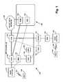
- FIG. 1illustrates an example wireless communication system 100 , which may be related to aspects of the present disclosure.
- wireless communication system 100includes two different types of base stations, exemplified by base station 112 and base station 114 .
- Base station 112e.g., an eNodeB
- RANevolved radio access network
- EPCEvolved Packet Core
- Base station 114is part of a legacy RAN that includes a radio network controller (RNC) 118 .
- Base stations 112 and 114each provide one or more respective wireless coverage areas through which the respective base station can communicate with one or more WCDs.
- the wireless coverage areas provided by base stations 112 and 114could be either overlapping or non-overlapping.
- the WCDscould be wireless telephones, wirelessly-equipped handheld, tablet, or laptop computers, or any other type of WCD. Some WCDs may be referred to as user equipment (UE). Despite this nomenclature, a WCD need not be an end-user device, and may instead be one of various types of devices that have limited directed interaction with human users, such as server devices, remote telemetry devices, and/or autonomous devices.
- UEuser equipment
- connections that carry bearer trafficare indicated by solid lines
- connections that carry signaling trafficare indicated by dashed lines
- connections that carry both bearer traffic and signaling trafficare indicated by solid lines in combination with dashed lines.
- both bearer and signaling trafficmay be communicated using interfaces and/or paths not explicitly marked as such in FIG. 1 .
- base station 112is in wireless communication with WCD 120 via an air interface 122
- base station 114is in wireless communication with WCD 124 via an air interface 126
- Each of air interfaces 122 and 126may include forward direction channels for communication from the RAN to WCDs, and reverse direction channels for communication from the WCDs to the RAN.
- Base stations 112 and 114may communicate with WCDs using different air interface protocols.
- base station 112communicates with WCDs, such as WCD 120 , using a Long Term Evolution (LTE) protocol
- base station 114communicates with WCDs, such as WCD 124 , using a High Rate Packet Data (HRPD) protocol, such as Evolution Data-Only (EVDO).
- HRPDHigh Rate Packet Data
- EVDOEvolution Data-Only
- base stations 112 and 114may communicate using any air interface protocol that is known currently or may be developed.
- EPC network 116includes a serving gateway (SGW) device 130 , a packet gateway (PGW) device 132 , a mobility management entity (MME) device 134 , a home subscriber server (HSS) device 136 , and a subscriber profile store (SPS) device 138 .
- PGW device 132may provide connectivity to a packet data network 140 .
- SGW device 130may support the exchange of Internet Protocol (IP) bearer traffic between base station 112 and PGW device 132 , and/or between base station 112 and PGW device 154 .
- MME device 134may manage signaling traffic between base station 112 and various elements in EPC network 116 , as well as signaling traffic between base station 112 and HSS device 152 .
- IPInternet Protocol
- This signaling trafficmay be related to authentication of WCDs and activating and de-activating bearer association for WCDs.
- HSS device 136may be configured to authenticate WCDs, as well as access subscriber profiles stored in SPS device 138 .
- SPS device 138may store subscriber profiles for WCDs that are authorized to use EPC network 116 .
- EPC network 116can provide packet data connections to packet data network 140 for WCDs served by base stations in an evolved RAN, for example, WCD 120 served by base station 112 .
- the packet data connections that EPC network 116 provides to WCDsmay, in turn, be used for web access, email, text, voice-over-IP (VoIP), video, streaming media, gaming, and/or other packet data services.
- VoIPvoice-over-IP
- a WCD subscribed to EPC network 116may be assigned PGW device 132 for bearer traffic communication with packet data network 140 .
- the bearer path for this WCDmay include base station 112 , SGW device 130 , and PGW device 132 .
- a WCD subscribed to network 150may be assigned PGW device 154 for bearer traffic communication. Therefore, the bearer path for this WCD may include base station 112 , SGW device 130 , and PGW device 154 .
- HSS device 152may be used to authenticate the WCD and/or to directly or indirectly assign PGW device 154 to serve the WCD.
- network 150 , HSS device 152 , and PGW device 154may be operated by a home wireless service provider, and the other components in FIG. 1 may be operated by a roaming wireless service provider.
- the home and roaming wireless service providersmay partner so that the roaming wireless service provider serves WCDs subscribed to the home wireless service provider when those WCDs cannot (or for some reason do not) obtain wireless coverage from the home wireless service provider.
- the signaling and/or data traffic exchanged between the home and roaming wireless service providersmay traverse packet data network 140 and/or one or more other networks or private peering gateways.
- WCD 120may access network 150 through an EPC network operated by the home wireless service provider.
- EPC network 116may provide packet data connections for WCDs served by other RANs, such as WCDs served by legacy RANs. Despite being served by these RANs, the WCDs may be subscribed to the roaming wireless service provider or the home wireless service provider.
- wireless communication system 100includes an HRPD serving gateway (HSGW) device 142 that supports interworking with a legacy RAN, exemplified in FIG. 1 by base station 114 and RNC device 118 , and authentication, authorization, and accounting (AAA) device 144 .
- This interworkingmay involve (i) HSGW device 142 communicating with AAA device 144 , which, in turn, may communicate with HSS device 136 , and (ii) HSGW device 142 communicating with PGW device 132 .
- WCD 124when served by base station 114 , may transmit a data-connection request that relates to establishing a packet data connection.
- HSGW device 142may receive the data-connection request via base station 114 and RNC device 118 , and, in response, communicate with AAA device 144 to authenticate WCD 124 .
- AAA device 144may perform various functions, such as communicating with HSS device 136 , issuing an authentication challenge to WCD 124 , evaluating a response (from WCD 124 ) to the authentication challenge, and indicating to HSGW device 142 whether the authentication process is successful or unsuccessful.
- HSGW device 142may communicate with PGW device 132 to request a packet data connection to packet data network 140 for WCD 124 .
- PGW device 132may communicate with AAA device 144 to authenticate WCD 124 in another authentication process. If that authentication process is successful, PGW device 132 may establish the packet data connection, which then enables WCD 124 to communicate with packet data network 140 via air interface 126 , base station 114 , RNC device 118 , HSGW device 142 , and PGW device 132 .
- a similar processmay be used so that WCD 124 may communicates via air interface 126 , base station 114 , RNC device 118 , HSGW device 142 , and PGW device 152 .
- FIG. 1In general, the depictions of FIG. 1 are illustrative. Therefore, in a RAN or a home network, there could be more or fewer of each element than is shown, and some elements may be omitted altogether. Additionally, other types of elements not shown may be present. Further, any of these elements or devices may be combined with one another, physically or logically, or distributed across multiple physical devices. Thus, the particular arrangement shown in FIG. 1 should not be viewed as limiting with respect to the present invention.
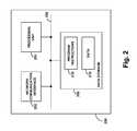
- FIG. 2is a block diagram of an example computing device 200 .
- Computing device 200could be a standalone general purpose or specialized computing device.
- computing device 200could be a WCD or a part of the RAN.
- computing device 200may represent a base station, MME device, SGW device, PGW device, HSS device, or some other type of RAN component or computer.
- computing device 200includes a network communication interface 202 , a processing unit 204 , and data storage 206 , all of which may be communicatively linked together by a system bus, network, or other connection mechanism 208 .
- Computing device 200may also include additional components, functions and/or interfaces not shown in FIG. 2 , such as a keyboard, a mouse, a touch screen, a monitor, a printer, and/or one or more ports that interface with such devices, for example a universal serial bus (USB) or high-definition multimedia interface (HDMI) port.
- USBuniversal serial bus
- HDMIhigh-definition multimedia interface
- Network communication interface 202may support communication with various other network entities, such as any of the network entities shown in FIG. 1 .
- interface 202may include one or more network interface modules, such as Ethernet, Wifi, BLUETOOTH®, and/or wide-area wireless connection network interface modules, or any other type of wired and/or wireless communication interfaces.
- Processing unit 204may comprise one or more general purpose processors (e.g., microprocessors) and/or one or more special purpose processors (e.g., application specific integrated circuits, digital signal processors, and/or network processors).
- Data storage 206may comprise one or more volatile and/or non-volatile non-transitory storage components, such as optical, magnetic, or flash storage, and may be integrated in whole or in part with processing unit 204 .
- data storage 206may hold program instructions 210 and data 212 .
- Program instructions 210may be executable by processing unit 204 to carry out various operations described herein and/or depicted in the accompanying drawings.
- Data 212could be any data that is generated, received, stored, or used in connection with carrying out such operations.
- FIGS. 3, 4, and 5may involve, directly or indirectly, WCD 300 , base station 302 , base station 400 , MME device 304 , SGW device 306 , SGW device 402 , HSS device 310 , PGW device 312 , and/or PGW device 314 .
- base station 302 , base station 400 , MME device 304 , SGW device 306 , and SGW device 402are operated by a roaming wireless service provider, while HSS device 310 , PGW device 312 , and PGW device 314 are operated by a home service provider.
- WCD 300may be subscribed to the home service provider.
- the roaming wireless service provider equipment and the home wireless service provider equipmentmay be in different countries, regions, or continents. However, other embodiments may be possible.
- various messagesmay be referred to with various labels, such as “connection request, “attach request,” “authentication request,” and so on.
- messages that perform the substantive operations described hereinmay be given different labels, or may be referred to differently.
- the operations of some messages shown in these figuresmay be performed by more or fewer messages.
- these figuresmay omit some messages that may be present in particular embodiments.
- FIG. 3illustrates one possible way in which WCD 300 can obtain wireless service from the roaming wireless service provider and the home wireless service provider.
- WCD 300has not yet been assigned an IP address by a home PGW device.
- WCD 300or its wireless interface, may have recently been powered on.
- WCD 300may transmit a connection request to base station 302 .
- base station 302may transmit an attach request to MME device 304 .
- MME device 304may determine that WCD 300 is subscribed to the home service provider. In doing so, MME device 304 may examine an identifier of WCD 300 , such as a network access identifier (NAI), international mobile subscriber identifier (IMSI), mobile equipment identifier (MEID), or some other type of device or user identifier. Based on this identifier, MME device 304 may determine that WCD 300 subscribes to the home wireless service provider, and that MME device 304 should request authentication of WCD 300 from HSS device 310 .
- NAInetwork access identifier
- IMSIinternational mobile subscriber identifier
- MEIDmobile equipment identifier
- MME device 304may transmit an authentication request to HSS device 310 .
- This authentication requestmay seek to determine whether WCD 300 has a valid subscription with the home wireless service provider, and/or whether the home wireless service provider will permit WCD 300 to use the services of the roaming wireless service provider.
- HSS device 310may look up the NAI, IMSI, MEID, or other identifier of WCD 300 in a local or remote subscriber database to make this determination.
- HSS device 310may transmit an authentication response to MME device 304 .
- the authentication responsemay include an indication of the IP address(es) assigned to WCD 300 .
- the indicationmay either be omitted from the authentication response, or may take on a default value (e.g., all zeroes) that represents a lack of IP address assignment.
- the authentication responsemay also indicate that the roaming wireless service provider should assign WCD 300 to one a particular group of one or more home PGW devices. This group may be associated with or referred to by a domain name, such as abc.com, or some other identifier. In choosing the domain name to include in the authentication response, the HSS device may determine whether the domain name should be statically or dynamically assigned.
- HSS device 310may select a domain name that is associated with or assigned to WCD 300 .
- the home wireless service provider of WCD 300may operate a limited number of home PGW devices, and the selected static domain name may be associated with these home PGW devices.
- HSS device 310may select, for example, a domain name that is associated with one or more home PGW devices that are topologically or geographically close to WCD 300 .
- MME device 304may look up abc.com to determine an IP address of a home PGW device to assign to WCD 300 .
- MME device 304may perform a Domain Name System (DNS) transaction with a DNS server (not shown).
- DNSDomain Name System
- MME device 304may request an IP address mapped to the domain name abc.com.
- the DNS servermay contain or have access to several such mappings. For example, in FIG. 3 , both home PGW device 312 and home PGW device 314 are associated with abc.com.
- the DNS servermay select one or more of the mapped IP addresses associated with these home PGW devices, and provide it to MME device 304 . If more than one mapped IP address is provided, MME device 304 may select one of the mapped IP addresses.
- the selectionmay be made on the basis of load balancing. For example, the selecting device may choose an IP address based on a round-robin or random procedure. Alternatively, the selecting device may choose an IP address based on some indication of load at the associated home PGW device.
- MME device 304obtains an IP address of a particular home PGW device. In the example illustrated in FIG. 3 , this is home PGW device 314 . Then, at step 328 , MME device 304 may transmit a create session request to SGW device 306 . Possibly among other functions, the create session request may instruct SGW device 306 to create a portion of a bearer path from itself to PGW device 314 . Accordingly, at step 330 , SGW device 306 may transmit a proxy binding update message to PGW device 314 , and PGW device 314 may respond, at step 332 , by transmitting a proxy binding update acknowledgement message to SGW device 306 .
- the proxy binding update and proxy binding update acknowledgment messagesmay be formed according to the mobile IPv6 protocol. Thus, these messages may be used to establish a bearer path between WCD 300 , base station 302 , SGW device 306 , and home PGW device 314 . At step 331 , these messages also may facilitate assignment, by home PGW device 314 , of one or more IP addresses to WCD 300 .
- the allocated IP addressesmay be IPv4 addresses, IPv6 addresses, or both.
- the proxy binding update acknowledgment messagemay include a representation of the assigned IP address(es).
- SGW device 306may transmit a create session response to MME device 304
- MME device 304may transmit an attach response to base station 302
- base station 302may transmit a connection response to WCD 300 , as part of these respective steps.
- a bearer pathhas been established for WCD 300 , possibly involving WCD 300 , base station 302 , SGW device 306 , and PGW device 314 .
- MME device 304 and HSS device 310might perform only signaling functions, and therefore might not be part of this bearer path.
- the bearer pathmay support a bearer association between WCD 300 and home PGW device 314 .
- WCD 300may use its assigned IP address(es) to exchange bearer traffic with correspondent nodes on a private network, a public network (e.g., the Internet), or with other devices and/or services within the home wireless service provider's network.
- This exchange of bearer trafficmay involve one or more communication sessions between the WCD and one or more correspondent nodes.
- the WCD's bearer trafficmay traverse both the SGW device and the home PGW device on its way to and from other devices and networks (e.g., web servers, gaming servers, email servers, etc.). Particularly, the WCD's bearer traffic may be tunneled between the SGW device and the home PGW device.
- the binding update message/binding update acknowledgment message transaction between the SGW device and the home PGW devicemay serve to establish the tunnel and further transactions of a similar nature may refresh the tunnel from time to time.
- a tunneloccurs when a particular network protocol encapsulates a payload protocol, and can be used to hide the topological details of a network from the encapsulated protocols and their applications.
- a tunnel between SGW device 306 and home PGW device 314may carry the communication sessions of WCD 300 as the payload protocol.
- a WCDmay be handed over to a different EPC network or a non-EPC network.
- This new access networkmay be operated by the WCD's home wireless service provider or another wireless service provider.
- the WCDmay be assigned to the same home PGW device. In this way, the home PGW device can continue serving the WCD's communication sessions in a manner that is transparent (or virtually transparent) to correspondent nodes.
- IP networkingIP addresses (along with other information, such as Transmission Control Protocol (TCP) and/or User Datagram Protocol (UDP) port numbers) may be used by applications when communicating.
- TCPTransmission Control Protocol
- UDPUser Datagram Protocol
- Each of a WCD's communication sessionsmay be identified by a unique combination of IP addresses and port numbers used by the endpoints of that communication session.
- a WCDis assigned IP address 168.192.0.100, and is communicating with a correspondent node (e.g., a web server) that is assigned IP address 10.172.15.7. Further, in this communication session, the WCD may be using TCP port 1025 and the correspondent node may be using TCP port 80.
- This 4-tuple of IP addresses and portsmay serve to identify a communication session.
- the communication sessioncan be used. If any of these four pieces of information changes, the communication session may fail. For instance, if the WCD is handed over to a new RAN and is ultimately assigned a different IP address, any ongoing TCP or UDP sessions using the WCD's old IP address become invalid, and may have to be restarted using the new IP address. In the case of multimedia sessions, such as a VoIP call or streaming video, any such a restart may result in a noticeable “break” in the session, or even a complete failure of the session. Other types of communication sessions may suffer a similar fate.
- WCD IP addressesmay be allocated by home PGW device itself, or by a home PGW device that coordinates the assignment of IP addresses with separate resource allocation servers (an example of which may be an AAA device or an HSS device). For instance, one or more pools of contiguous IP addresses may be allocated to each home PGW device, such that each IP address in such pools is allocated to a unique home PGW device. A particular home PGW device may assign IP addresses from its pool(s) to WCDs that communicate via the particular home PGW device.
- the new SGW devicewhen a WCD is handed over to a new SGW device, it is beneficial for the new SGW device to establish a bearer association with the home PGW device from which the WCD's IP address(es) have been allocated, instead of with some other PGW device. In this way, the home PGW device that assigned the WCD's IP address(es) can help maintain the WCD's communication sessions.
- the home PGW devicemay be selected from a group of available home PGW devices. If the previously-selected home PGW device is not selected again, a bearer association may be established with a new home PGW device. Since this new home PGW device will have been allocated different IP address pools than the previously-selected home PGW device, the new home PGW device will be unable to support the WCD communicating via the its assign IP address(es). As a result, the WCD's communication sessions with the new home PGW device may fail.
- FIG. 4illustrates this possibility.
- FIG. 4continues the example of FIG. 3 , but assumes that WCD 300 has been handed over to base station 400 at some point after step 340 .
- Base station 400communicates via SGW device 402 .
- WCD 300may transmit a connection request to base station 400 .
- base station 400may transmit an attach request to MME device 304 .
- MME device 304may determine that WCD 300 is subscribed to the home service provider.
- MME device 304may transmit an authentication request to HSS device 310 .
- HSS device 310may transmit an authentication response to MME 304 .
- the authentication responsemay indicate that the roaming wireless service provider should assign WCD 300 to one a particular group of one or more home PGW devices associated with the domain name abc.com.
- the authentication responsemay also include a representation of the IP address(es) assigned to WCD 300 by home PGW device 314 .
- MME device 304may look up abc.com to determine an IP address of a home PGW device to assign to WCD 300 . Again, MME device 304 may perform a DNS transaction with a DNS server to map abc.com to a home PGW device IP address. In this transaction, however, MME device 304 winds up with the IP address of home PGW device 312 , rather than the IP address of home PGW device 314 . Recall that load balancing may be used to select the home PGW device IP address. Thus, there is no guarantee that the same home PGW device is selected after WCD 300 has been handed over to a new SGW device.
- MME device 304may transmit a create session request to SGW device 402 .
- the create session request messagemay include a representation of the IP address(es) assigned to WCD 300 by home PGW device 314 .
- SGW device 402may transmit a proxy binding update message to home PGW device 312 .
- the proxy binding update messagemay also include a representation of the IP address(es) assigned to WCD 300 by home PGW device 314 .
- home PGW device 312responds by transmitting a proxy binding update acknowledgement message that indicates an invalid session. Since home PGW device 312 does not support these IP address(es), home PGW device 312 may reject the request of step 416 .
- WCD 300was allocated IPv4 address 192.168.227.14 by home PGW device 314 .
- home PGW device 312only supports the IP address pools of 192.168.20.0-192.168.21.255 and 192.168.223.0-192.168.223.127.
- PGW device 312can determine that 192.168.227.14 falls outside of the ranges of IP addresses in its pools, and therefore communication with WCD 300 using 192.168.227.14 cannot be supported.
- Steps 420 , 422 , and 424involve SGW device 402 transmitting a create session response to MME device 304 , MME device 304 transmitting an attach response to base station 400 , and base station 400 transmitting a connection response to WCD 300 . These three steps may serve to inform WCD 300 that its bearer association with home PGW device 312 has failed.
- WCD 300may indicate to its user that the session has failed.
- home PGW device 312may assign one or more new IP addresses to WCD 300 , and a bearer path involving WCD 300 , base station 400 , SGW device 402 , and home PGW device 312 may be established. Nonetheless, for reasons noted above, the existing communication sessions of WCD 300 may fail, and WCD 300 may have to establish new communication sessions with any correspondent nodes.
- the message flow illustrated by FIG. 5provides a way for WCD 300 to maintain its bearer association with home PGW device 314 , as well as maintain its assigned IP address(es).
- FIG. 5continues the example of FIG. 3 , assuming that WCD 300 has been handed over to base station 400 at some point after step 340 .
- WCD 300may transmit a connection request to base station 400 .
- base station 400may transmit an attach request to MME device 304 .
- MME device 304may determine that WCD 300 is subscribed to the home service provider.
- MME device 304may transmit an authentication request to HSS device 310 .
- HSS device 310may transmit an authentication response to MME device 304 .
- the authentication responsemay indicate that the roaming wireless service provider should assign WCD 300 to one a particular group of one or more home PGW devices associated with the domain name abc.com.
- the authentication responsemay also include a representation of the IP address(es) assigned to WCD 300 by home PGW device 314 .
- MME device 304may look up abc.com to determine an IP address of a home PGW device to assign to WCD 300 .
- MME device 304may perform a DNS transaction with a DNS server to map abc.com to a home PGW device IP address. In this transaction, MME device 304 winds up with the IP address of home PGW device 312 , rather than the IP address of home PGW device 314 .
- MME device 304may transmit a create session request to SGW device 402 .
- the create session request messagemay include a representation of the IP address(es) assigned to WCD 300 by home PGW device 314 .
- SGW device 402may transmit a proxy binding update message to home PGW device 312 .
- the proxy binding update messagemay also include a representation of the IP address(es) assigned to WCD 300 by home PGW device 314 .
- home PGW device 312determines that the proxy binding update should instead be sent to home PGW device 314 so that WCD 300 can maintain its bearer association with that PGW device.
- home PGW device 312(as well as the other home PGW devices associated with abc.com) may have access to a database that maps IP address pools to home PGW devices.
- a copy of this databasemay be stored on each home PGW device associated with abc.com, or may be centrally stored (e.g., in an AAA device, HSS device, or a similar device).
- home PGW device 312may look up the assigned IP address(es) of WCD 300 (provided to home PGW device 312 at step 512 ), and determine that these IP address(es) do not fall within the pools of home PGW device 312 , but do fall within the pools of home PGW device 314 .
- home PGW device 312may forward the proxy binding update to home PGW device 314 .
- Home PGW device 314may respond in turn, at step 332 , by transmitting a proxy binding update acknowledgement message to SGW device 402 .
- the proxy binding update acknowledgement messagemay additionally include an indication to SGW device 402 that home PGW device 314 is serving WCD 300 , and that future proxy binding update messages related to WCD 300 should be sent directly to home PGW device 314 .
- SGW device 402may associate PGW device 314 with WCD 300 . Further, at steps 522 , 524 , and 526 , SGW device 402 may transmit a create session response to MME device 304 , MME device 304 may transmit an attach response to base station 400 , and base station 400 may transmit a connection response to WCD 300 , respectively.
- a bearer pathhas been established for WCD 300 , possibly involving WCD 300 , base station 400 , SGW device 402 , and PGW device 314 .
- WCD 300may use its assigned IP addresses to exchange bearer traffic with correspondent nodes on a private network, a public network (e.g., the Internet), or with other devices and/or services within the home wireless service provider's network. In this way, WCD 300 has been handed off between SGW device 306 and SGW device 402 , but its bearer association, and the communication sessions supported thereby, remain anchored at home PGW device 314 .
- FIG. 6is a flow chart in accordance with example embodiments. The operations illustrated by this flow chart may be carried out by a computing device, such as computing device 200 .
- computing device 200may represent a home PGW device.
- a first home packet gateway PGW devicemay receive a binding update message on behalf of a WCD.
- the first home PGW devicemay be associated with a first pool of IP addresses, and the WCD may be assigned a particular IP address.
- the first pool of IP addressesdoes not include the particular IP address.
- the first home PGW devicemay forward the binding update message to the second home PGW device.
- the binding update messagemay indicate that the WCD has recently moved from being served by a first SGW device to being served by a second SGW device. Forwarding the binding update message to the second home PGW device may also be in response to the WCD having recently moved from being served by the first SGW device to being served by the second SGW device.
- the first SGW device and the second SGW devicemay be operated by different wireless service providers. Alternatively or additionally, the first SGW device and the second SGW device may serve WCDs using different air interfaces, such as “4G” LTE, “3G” CDMA, Wifi, etc.
- the second home PGW devicemay receive the binding update message. Possibly in response to receiving the binding update message, the second home PGW device may transmit a binding update response message to the second SGW device.
- the binding update response messagemay include an indication that the binding update message was forwarded to the second home PGW device from another home PGW device.
- the binding update messagemay be a mobile IPv4 registration request message or IPv6 proxy binding update message
- the binding update response messagemay be a mobile IPv4 registration response message or a mobile IPv6 proxy binding update acknowledgement message.
- FIG. 6The embodiments depicted in FIG. 6 are merely examples, and other embodiments may be possible. For instance, any of the features associated with any of FIGS. 3, 4 , and/or 5 may be combined with the embodiments of FIG. 6 .
- each step, block, and/or communicationcan represent a processing of information and/or a transmission of information in accordance with example embodiments.
- Alternative embodimentsare included within the scope of these example embodiments.
- functions described as steps, blocks, transmissions, communications, requests, responses, and/or messagescan be executed out of order from that shown or discussed, including substantially concurrent or in reverse order, depending on the functionality involved.
- more or fewer blocks and/or functionscan be used with any of the ladder diagrams, scenarios, and flow charts discussed herein, and these ladder diagrams, scenarios, and flow charts can be combined with one another, in part or in whole.
- a step or block that represents a processing of informationcan correspond to circuitry that can be configured to perform the specific logical functions of a herein-described method or technique.
- a step or block that represents a processing of informationcan correspond to a module, a segment, or a portion of program code (including related data).
- the program codecan include one or more instructions executable by a processor for implementing specific logical functions or actions in the method or technique.
- the program code and/or related datacan be stored on any type of computer readable medium such as a storage device including a disk, hard drive, or other storage medium.
- the computer readable mediumcan also include non-transitory computer readable media such as computer-readable media that store data for short periods of time like register memory, processor cache, and random access memory (RAM).
- the computer readable mediacan also include non-transitory computer readable media that store program code and/or data for longer periods of time.
- the computer readable mediamay include secondary or persistent long term storage, like read only memory (ROM), optical or magnetic disks, compact-disc read only memory (CD-ROM), for example.
- the computer readable mediacan also be any other volatile or non-volatile storage systems.
- a computer readable mediumcan be considered a computer readable storage medium, for example, or a tangible storage device.
- a step or block that represents one or more information transmissionscan correspond to information transmissions between software and/or hardware modules in the same physical device.
- other information transmissionscan be between software modules and/or hardware modules in different physical devices.
Landscapes
- Engineering & Computer Science (AREA)
- Computer Networks & Wireless Communication (AREA)
- Signal Processing (AREA)
- Databases & Information Systems (AREA)
- Mobile Radio Communication Systems (AREA)
Abstract
Description
Claims (20)
Priority Applications (1)
| Application Number | Priority Date | Filing Date | Title |
|---|---|---|---|
| US14/520,867US9445256B1 (en) | 2014-10-22 | 2014-10-22 | Binding update forwarding between packet gateways |
Applications Claiming Priority (1)
| Application Number | Priority Date | Filing Date | Title |
|---|---|---|---|
| US14/520,867US9445256B1 (en) | 2014-10-22 | 2014-10-22 | Binding update forwarding between packet gateways |
Publications (1)
| Publication Number | Publication Date |
|---|---|
| US9445256B1true US9445256B1 (en) | 2016-09-13 |
Family
ID=56881455
Family Applications (1)
| Application Number | Title | Priority Date | Filing Date |
|---|---|---|---|
| US14/520,867Active2035-02-06US9445256B1 (en) | 2014-10-22 | 2014-10-22 | Binding update forwarding between packet gateways |
Country Status (1)
| Country | Link |
|---|---|
| US (1) | US9445256B1 (en) |
Cited By (6)
| Publication number | Priority date | Publication date | Assignee | Title |
|---|---|---|---|---|
| US10091160B2 (en)* | 2014-03-12 | 2018-10-02 | British Telecommunications Public Limited Company | Wireless access gateway |
| US10237796B1 (en) | 2016-03-07 | 2019-03-19 | Sprint Spectrum L.P. | Packet gateway reassignment |
| CN112363667A (en)* | 2020-11-12 | 2021-02-12 | 四川长虹电器股份有限公司 | Touch remote control method and system |
| US11375424B2 (en)* | 2017-06-23 | 2022-06-28 | Blackned Gmbh | Network access entity for dynamically reconfigurable networks |
| CN114826808A (en)* | 2022-04-14 | 2022-07-29 | 中国联合网络通信集团有限公司 | Method and device for accessing user terminal to network, user terminal and storage medium |
| US11451489B2 (en) | 2014-03-12 | 2022-09-20 | British Telecommunications Public Limited Company | Wireless access gateway |
Citations (51)
| Publication number | Priority date | Publication date | Assignee | Title |
|---|---|---|---|---|
| US6230012B1 (en) | 1998-08-07 | 2001-05-08 | Qualcomm Incorporated | IP mobility support using proxy mobile node registration |
| US20020136226A1 (en)* | 2001-03-26 | 2002-09-26 | Bluesocket, Inc. | Methods and systems for enabling seamless roaming of mobile devices among wireless networks |
| US20030208601A1 (en) | 2001-10-25 | 2003-11-06 | Campbell Edward P. | System and method for session control in a mobile internet protocol network |
| US6697354B1 (en) | 1998-03-05 | 2004-02-24 | 3Com Corporation | Method and system for distributed network address translation for mobile network devices |
| US6708219B1 (en) | 1999-10-26 | 2004-03-16 | 3Com Corporation | Method and system for dual-network address utilization |
| US6711159B1 (en) | 1999-12-15 | 2004-03-23 | 3Com Corporation | Load balancing among media gateways |
| US6731642B1 (en) | 1999-05-03 | 2004-05-04 | 3Com Corporation | Internet telephony using network address translation |
| US20040095943A1 (en)* | 2002-11-15 | 2004-05-20 | Korotin Dmitry O. | Apparatus and method for preserving routable IP addresses using ARP proxy |
| US6768743B1 (en) | 1999-10-26 | 2004-07-27 | 3Com Corporation | Method and system for address server redirection for multiple address networks |
| US6781982B1 (en) | 1999-10-26 | 2004-08-24 | 3Com Corporation | Method and system for allocating persistent private network addresses between private networks |
| US6816912B1 (en) | 2000-12-01 | 2004-11-09 | Utstarcom, Inc. | Method and system for tunnel optimized call setup for mobile nodes |
| US20050047420A1 (en) | 2003-07-01 | 2005-03-03 | Shiro Tanabe | Mobile IPv6 network having multiple home agents and method of load balance |
| US6956846B2 (en) | 2002-08-16 | 2005-10-18 | Utstarcom Incorporated | System and method for foreign agent control node redundancy in a mobile internet protocol network |
| US6973309B1 (en) | 2002-03-14 | 2005-12-06 | Utstarcom, Inc. | Method and system for re-direction and handoff for pre-paid mobile services in third generation networks |
| US20060002356A1 (en) | 2004-07-01 | 2006-01-05 | Barany Peter A | Dynamic assignment of home agent and home address in wireless communications |
| US6993039B2 (en) | 2002-07-22 | 2006-01-31 | Utstarcom, Inc. | System and method for GRE heartbeats |
| US6996621B1 (en) | 1999-12-07 | 2006-02-07 | 3Com Corporation | Method for supporting secondary address delivery on remote access servers |
| US20060059551A1 (en) | 2004-09-13 | 2006-03-16 | Utstarcom Inc. | Dynamic firewall capabilities for wireless access gateways |
| US7031275B1 (en) | 2000-12-28 | 2006-04-18 | Utstarcom, Inc. | Address management for mobile nodes |
| US20060104214A1 (en) | 2004-11-18 | 2006-05-18 | Borella Michael S | System and method for automated provisioning of wireless access gateways |
| US20060149814A1 (en) | 2004-12-30 | 2006-07-06 | Utstarcom, Inc. | Method and apparatus for presence status facilitation by an access gateway in a mobile communications system |
| US7080151B1 (en) | 2002-04-01 | 2006-07-18 | Utstarcom, Inc. | Method and system for mobile IP home agent redundancy by using home agent control nodes for managing multiple home agents |
| US20060159042A1 (en) | 2005-01-20 | 2006-07-20 | Utstarcom, Inc. | Method and apparatus to facilitate foreign agent actions with respect to home agent nonresponsiveness |
| US20060171365A1 (en) | 2005-02-02 | 2006-08-03 | Utstarcom, Inc. | Method and apparatus for L2TP dialout and tunnel switching |
| US7154868B1 (en) | 2002-01-08 | 2006-12-26 | Utstarcom, Inc. | Smooth handoff via state exchange in wireless networks |
| US7158492B2 (en) | 2000-03-13 | 2007-01-02 | Nokia Corporation | Load balancing in telecommunications system supporting mobile IP |
| US7193985B1 (en) | 2001-06-14 | 2007-03-20 | Utstarcom, Inc. | System and method for managing foreign agent selections in a mobile internet protocol network |
| US7218609B2 (en) | 2002-08-30 | 2007-05-15 | Utstarcom, Inc. | Method and system of transferring session speed and state information between access and home networks |
| US7280546B1 (en) | 2002-11-25 | 2007-10-09 | Utstarcom, Inc. | Method and system for providing wireless internet protocol access |
| US7286512B1 (en) | 2003-03-07 | 2007-10-23 | Utstar, Inc. | System and method for supporting alternative addressessing in a mobile network |
| US7295511B2 (en) | 2002-06-13 | 2007-11-13 | Utstarcom, Inc. | System and method for packet data serving node load balancing and fault tolerance |
| US7305429B2 (en) | 2002-06-10 | 2007-12-04 | Utstarcom, Inc. | Method and apparatus for global server load balancing |
| US7324499B1 (en) | 2003-06-30 | 2008-01-29 | Utstarcom, Inc. | Method and system for automatic call monitoring in a wireless network |
| US7346684B2 (en) | 2003-01-31 | 2008-03-18 | Utstarcom, Inc. | System and method for control of packet data serving node selection in a mobile internet protocol network |
| US7366509B2 (en) | 2004-03-18 | 2008-04-29 | Utstarcom, Inc. | Method and system for identifying an access point into a wireless network |
| US7457289B2 (en) | 2002-12-16 | 2008-11-25 | Cisco Technology, Inc. | Inter-proxy communication protocol for mobile IP |
| US7505432B2 (en) | 2003-04-28 | 2009-03-17 | Cisco Technology, Inc. | Methods and apparatus for securing proxy Mobile IP |
| US20100020747A1 (en) | 2008-07-22 | 2010-01-28 | Futurewei Technologies, Inc. | Method and Apparatus for Home Agent Redirect |
| US7733904B1 (en) | 2002-01-28 | 2010-06-08 | 3Com Corporation | System and method for roaming between wireless networks |
| US7778220B2 (en) | 2006-11-06 | 2010-08-17 | Cisco Technology, Inc. | Method to loadbalance among mobile IPv6 home agents |
| US7813316B2 (en) | 2007-06-26 | 2010-10-12 | Cisco Technology, Inc. | Load balancing for mobile IP home agents |
| US20110286410A1 (en)* | 2009-09-18 | 2011-11-24 | Nec Europe Ltd. | Communication system and communication controlling method |
| US20120084449A1 (en) | 2010-10-05 | 2012-04-05 | Verizon Patent And Licensing Inc. | Dynamic selection of packet data network gateways |
| US8341295B1 (en) | 2004-10-29 | 2012-12-25 | Akamai Technologies, Inc. | Server failover using IPV6 mobility features |
| US8411858B2 (en) | 2007-03-28 | 2013-04-02 | Apple Inc. | Dynamic foreign agent-home agent security association allocation for IP mobility systems |
| US8422467B2 (en) | 2002-02-20 | 2013-04-16 | Cisco Technology, Inc. | Methods and apparatus for supporting proxy mobile IP registration in a wireless local area network |
| US20130100815A1 (en) | 2011-10-19 | 2013-04-25 | Verizon Patent And Licensing Inc. | Optimized network node selection |
| US8437305B2 (en) | 2005-11-23 | 2013-05-07 | Cisco Technology, Inc. | Method for providing home agent geographic redundancy |
| US20130322311A1 (en) | 2008-02-18 | 2013-12-05 | Panasonic Corporation | Home agent discovery upon changing the mobility management scheme |
| US20140169330A1 (en)* | 2012-12-14 | 2014-06-19 | Telefonaktiebolaget L M Ericsson (Publ) | Network Gateway Selection at Multipath Communication |
| US20150312806A1 (en)* | 2012-11-30 | 2015-10-29 | Interdigital Patent Holdings, Inc. | Distributed mobility management technology in a network environment |
- 2014
- 2014-10-22USUS14/520,867patent/US9445256B1/enactiveActive
Patent Citations (54)
| Publication number | Priority date | Publication date | Assignee | Title |
|---|---|---|---|---|
| US6697354B1 (en) | 1998-03-05 | 2004-02-24 | 3Com Corporation | Method and system for distributed network address translation for mobile network devices |
| US6230012B1 (en) | 1998-08-07 | 2001-05-08 | Qualcomm Incorporated | IP mobility support using proxy mobile node registration |
| US6731642B1 (en) | 1999-05-03 | 2004-05-04 | 3Com Corporation | Internet telephony using network address translation |
| US6781982B1 (en) | 1999-10-26 | 2004-08-24 | 3Com Corporation | Method and system for allocating persistent private network addresses between private networks |
| US6708219B1 (en) | 1999-10-26 | 2004-03-16 | 3Com Corporation | Method and system for dual-network address utilization |
| US6768743B1 (en) | 1999-10-26 | 2004-07-27 | 3Com Corporation | Method and system for address server redirection for multiple address networks |
| US6996621B1 (en) | 1999-12-07 | 2006-02-07 | 3Com Corporation | Method for supporting secondary address delivery on remote access servers |
| US6711159B1 (en) | 1999-12-15 | 2004-03-23 | 3Com Corporation | Load balancing among media gateways |
| US7158492B2 (en) | 2000-03-13 | 2007-01-02 | Nokia Corporation | Load balancing in telecommunications system supporting mobile IP |
| US6816912B1 (en) | 2000-12-01 | 2004-11-09 | Utstarcom, Inc. | Method and system for tunnel optimized call setup for mobile nodes |
| US7031275B1 (en) | 2000-12-28 | 2006-04-18 | Utstarcom, Inc. | Address management for mobile nodes |
| US20020136226A1 (en)* | 2001-03-26 | 2002-09-26 | Bluesocket, Inc. | Methods and systems for enabling seamless roaming of mobile devices among wireless networks |
| US20070171886A1 (en) | 2001-06-14 | 2007-07-26 | Utstarcom, Incorporated | System and method for managing foreign agent selections in a mobile internet protocol network |
| US7193985B1 (en) | 2001-06-14 | 2007-03-20 | Utstarcom, Inc. | System and method for managing foreign agent selections in a mobile internet protocol network |
| US20030208601A1 (en) | 2001-10-25 | 2003-11-06 | Campbell Edward P. | System and method for session control in a mobile internet protocol network |
| US7154868B1 (en) | 2002-01-08 | 2006-12-26 | Utstarcom, Inc. | Smooth handoff via state exchange in wireless networks |
| US8396076B2 (en) | 2002-01-28 | 2013-03-12 | Hewlett-Packard Development Company, L.P. | System and method for roaming between wireless networks |
| US8107496B2 (en) | 2002-01-28 | 2012-01-31 | Hewlett-Packard Company | System and method for roaming between wireless networks |
| US7733904B1 (en) | 2002-01-28 | 2010-06-08 | 3Com Corporation | System and method for roaming between wireless networks |
| US8422467B2 (en) | 2002-02-20 | 2013-04-16 | Cisco Technology, Inc. | Methods and apparatus for supporting proxy mobile IP registration in a wireless local area network |
| US6973309B1 (en) | 2002-03-14 | 2005-12-06 | Utstarcom, Inc. | Method and system for re-direction and handoff for pre-paid mobile services in third generation networks |
| US7080151B1 (en) | 2002-04-01 | 2006-07-18 | Utstarcom, Inc. | Method and system for mobile IP home agent redundancy by using home agent control nodes for managing multiple home agents |
| US7305429B2 (en) | 2002-06-10 | 2007-12-04 | Utstarcom, Inc. | Method and apparatus for global server load balancing |
| US7295511B2 (en) | 2002-06-13 | 2007-11-13 | Utstarcom, Inc. | System and method for packet data serving node load balancing and fault tolerance |
| US6993039B2 (en) | 2002-07-22 | 2006-01-31 | Utstarcom, Inc. | System and method for GRE heartbeats |
| US6956846B2 (en) | 2002-08-16 | 2005-10-18 | Utstarcom Incorporated | System and method for foreign agent control node redundancy in a mobile internet protocol network |
| US7218609B2 (en) | 2002-08-30 | 2007-05-15 | Utstarcom, Inc. | Method and system of transferring session speed and state information between access and home networks |
| US20040095943A1 (en)* | 2002-11-15 | 2004-05-20 | Korotin Dmitry O. | Apparatus and method for preserving routable IP addresses using ARP proxy |
| US7280546B1 (en) | 2002-11-25 | 2007-10-09 | Utstarcom, Inc. | Method and system for providing wireless internet protocol access |
| US7457289B2 (en) | 2002-12-16 | 2008-11-25 | Cisco Technology, Inc. | Inter-proxy communication protocol for mobile IP |
| US7346684B2 (en) | 2003-01-31 | 2008-03-18 | Utstarcom, Inc. | System and method for control of packet data serving node selection in a mobile internet protocol network |
| US7286512B1 (en) | 2003-03-07 | 2007-10-23 | Utstar, Inc. | System and method for supporting alternative addressessing in a mobile network |
| US7505432B2 (en) | 2003-04-28 | 2009-03-17 | Cisco Technology, Inc. | Methods and apparatus for securing proxy Mobile IP |
| US7324499B1 (en) | 2003-06-30 | 2008-01-29 | Utstarcom, Inc. | Method and system for automatic call monitoring in a wireless network |
| US20050047420A1 (en) | 2003-07-01 | 2005-03-03 | Shiro Tanabe | Mobile IPv6 network having multiple home agents and method of load balance |
| US7366509B2 (en) | 2004-03-18 | 2008-04-29 | Utstarcom, Inc. | Method and system for identifying an access point into a wireless network |
| US20060002356A1 (en) | 2004-07-01 | 2006-01-05 | Barany Peter A | Dynamic assignment of home agent and home address in wireless communications |
| US20060059551A1 (en) | 2004-09-13 | 2006-03-16 | Utstarcom Inc. | Dynamic firewall capabilities for wireless access gateways |
| US8341295B1 (en) | 2004-10-29 | 2012-12-25 | Akamai Technologies, Inc. | Server failover using IPV6 mobility features |
| US20060104214A1 (en) | 2004-11-18 | 2006-05-18 | Borella Michael S | System and method for automated provisioning of wireless access gateways |
| US20060149814A1 (en) | 2004-12-30 | 2006-07-06 | Utstarcom, Inc. | Method and apparatus for presence status facilitation by an access gateway in a mobile communications system |
| US20060159042A1 (en) | 2005-01-20 | 2006-07-20 | Utstarcom, Inc. | Method and apparatus to facilitate foreign agent actions with respect to home agent nonresponsiveness |
| US20060171365A1 (en) | 2005-02-02 | 2006-08-03 | Utstarcom, Inc. | Method and apparatus for L2TP dialout and tunnel switching |
| US8437305B2 (en) | 2005-11-23 | 2013-05-07 | Cisco Technology, Inc. | Method for providing home agent geographic redundancy |
| US7778220B2 (en) | 2006-11-06 | 2010-08-17 | Cisco Technology, Inc. | Method to loadbalance among mobile IPv6 home agents |
| US8411858B2 (en) | 2007-03-28 | 2013-04-02 | Apple Inc. | Dynamic foreign agent-home agent security association allocation for IP mobility systems |
| US7813316B2 (en) | 2007-06-26 | 2010-10-12 | Cisco Technology, Inc. | Load balancing for mobile IP home agents |
| US20130322311A1 (en) | 2008-02-18 | 2013-12-05 | Panasonic Corporation | Home agent discovery upon changing the mobility management scheme |
| US20100020747A1 (en) | 2008-07-22 | 2010-01-28 | Futurewei Technologies, Inc. | Method and Apparatus for Home Agent Redirect |
| US20110286410A1 (en)* | 2009-09-18 | 2011-11-24 | Nec Europe Ltd. | Communication system and communication controlling method |
| US20120084449A1 (en) | 2010-10-05 | 2012-04-05 | Verizon Patent And Licensing Inc. | Dynamic selection of packet data network gateways |
| US20130100815A1 (en) | 2011-10-19 | 2013-04-25 | Verizon Patent And Licensing Inc. | Optimized network node selection |
| US20150312806A1 (en)* | 2012-11-30 | 2015-10-29 | Interdigital Patent Holdings, Inc. | Distributed mobility management technology in a network environment |
| US20140169330A1 (en)* | 2012-12-14 | 2014-06-19 | Telefonaktiebolaget L M Ericsson (Publ) | Network Gateway Selection at Multipath Communication |
Non-Patent Citations (11)
| Title |
|---|
| "(LTE) Attach and Default Bearer Setup," www.eventhelix.com/lte/attach/lte-attach.pdf, Dec. 11, 2012, 6 pages. |
| 3rd Generation Partnership Project 2 "3GPP2," "cdma2000 Wireless IP Network Standard: Simple IP and Mobile IP Access Services," 3GPP2 X.S0011-002-E, Version 1, Nov. 2009, 116 pages. |
| 3rd Generation Partnership Project 2 "3GPP2," "Network PMIP Support Revision A," 3GGP2 X.S0054-220-A, Version 1.0, Aug. 29, 2008, 50 pages. |
| 3rd Generation Partnership Project 2 "3GPP2," Interoperability Specification (IOS) for cdma2000 Access Network Interfaces-Part 1 Overview (3G-10S v5.0.4), Mar. 2014, 28 pages. |
| 3rd Generation Partnership Project 2 "3GPP2," Interoperability Specification (IOS) for cdma2000 Access Network Interfaces-Part 2 Transport (3G-10S v5.1.4), Mar. 2014, 78 pages. |
| 3rd Generation Partnership Project 2 "3GPP2," Interoperability Specification (IOS) for cdma2000 Access Network Interfaces-Part 3 Features (3G-10S v5.0.4), Mar. 2014, 386 pages. |
| ETSI TS 129 275 V11.9.0, Technical Specification, Universal Mobile Telecommunications System (UMTS); LTE; Proxy Mobile IPv6 (PMIPv6) based Mobility and Tunnelling protocols; Stage 3 (3GPP TS 29.275 version 11.9.0 Release 11), Mar. 2014, 88 pages. |
| Network Working Group, "IP Mobility Support for IPv4," C. Perkins, Ed., Nokia Research Center, Aug. 2002, https://www.iett.org/rfc/rfc3344.txt, 91 pages. |
| Notice of Allowance mailed on Jan. 28, 2016, issued in connection with U.S. Appl. No. 14/229,432, filed Mar. 28, 2014, 8 pages. |
| Preinterview First Office Action mailed on Oct. 26, 2015, issued in connection with U.S. Appl. No. 14/229,432, filed Mar. 28, 2014, 5 pages. |
| Xue et al., U.S. Appl. No. 14/229,432, filed Mar. 28, 2014, 42 pages. |
Cited By (7)
| Publication number | Priority date | Publication date | Assignee | Title |
|---|---|---|---|---|
| US10091160B2 (en)* | 2014-03-12 | 2018-10-02 | British Telecommunications Public Limited Company | Wireless access gateway |
| US11451489B2 (en) | 2014-03-12 | 2022-09-20 | British Telecommunications Public Limited Company | Wireless access gateway |
| US10237796B1 (en) | 2016-03-07 | 2019-03-19 | Sprint Spectrum L.P. | Packet gateway reassignment |
| US11375424B2 (en)* | 2017-06-23 | 2022-06-28 | Blackned Gmbh | Network access entity for dynamically reconfigurable networks |
| CN112363667A (en)* | 2020-11-12 | 2021-02-12 | 四川长虹电器股份有限公司 | Touch remote control method and system |
| CN114826808A (en)* | 2022-04-14 | 2022-07-29 | 中国联合网络通信集团有限公司 | Method and device for accessing user terminal to network, user terminal and storage medium |
| CN114826808B (en)* | 2022-04-14 | 2023-09-19 | 中国联合网络通信集团有限公司 | User terminal access network method and device, user terminal and storage medium |
Similar Documents
| Publication | Publication Date | Title |
|---|---|---|
| US11463946B2 (en) | System and method for UE context and PDU session context management | |
| US10455403B2 (en) | Virtual mobility anchor for network sharing | |
| US11089542B2 (en) | Terminal apparatus, base station apparatus, mobility management entity (MME), and communication control method | |
| KR102437811B1 (en) | Method and apparatus for session management function selection | |
| US9277522B2 (en) | Exchanging rich communication suite capability information in a communications system | |
| US11228560B2 (en) | Mobility functionality for a cloud-based access system | |
| US9445256B1 (en) | Binding update forwarding between packet gateways | |
| US9544927B2 (en) | System, method and computer readable medium for bearer activation in a core network for wireless devices | |
| JP5214737B2 (en) | Method and apparatus for use in a communication network | |
| KR101086349B1 (en) | Network and computer program product related to operation control method and system of communication network | |
| US9215256B2 (en) | Updating contact information for client devices registered to the same user for an internet protocol multimedia subsystem service | |
| JP6909772B2 (en) | Infrastructure-based D2D connection configuration using OTT services | |
| US20170026896A1 (en) | Terminal device, relay terminal device, and communication control method | |
| US10342054B2 (en) | IP address assignment for a UE in 3GPP | |
| US20070165655A1 (en) | Combining IP and cellular mobility | |
| US8565129B1 (en) | Supporting simple IP with address translation in a proxy mobile IP gateway | |
| US8780796B1 (en) | System and method for providing network initiated mobile access in a network environment | |
| JP2014505445A (en) | Notification of UE application trigger request from the network application server to the user equipment UE through the mobile network | |
| US8385300B2 (en) | Internet protocol address management for communicating packets in a network environment | |
| CN104427568B (en) | A method and device for realizing 3GPP network traffic offloading | |
| US8634394B1 (en) | Mechanism to verify packet data network support for internet protocol mobility | |
| JP7040763B2 (en) | Gateway devices, methods, programs, and recording media | |
| US20090154422A1 (en) | Method of providing seamless qos guarantees in internet protocol (ip) network when ip-based mobility service is provided | |
| US9350604B1 (en) | Packet gateway assignment based on network connectivity | |
| CN103188657A (en) | Method and system for assigning IP addresses to UE |
Legal Events
| Date | Code | Title | Description |
|---|---|---|---|
| AS | Assignment | Owner name:SPRINT SPECTRUM L.P., KANSAS Free format text:ASSIGNMENT OF ASSIGNORS INTEREST;ASSIGNORS:COLE, JAY D.;XUE, WEN;JAMSHIDI, TALAT;AND OTHERS;REEL/FRAME:034008/0345 Effective date:20141021 | |
| STCF | Information on status: patent grant | Free format text:PATENTED CASE | |
| AS | Assignment | Owner name:DEUTSCHE BANK TRUST COMPANY AMERICAS, NEW YORK Free format text:GRANT OF FIRST PRIORITY AND JUNIOR PRIORITY SECURITY INTEREST IN PATENT RIGHTS;ASSIGNOR:SPRINT SPECTRUM L.P.;REEL/FRAME:041937/0632 Effective date:20170203 | |
| MAFP | Maintenance fee payment | Free format text:PAYMENT OF MAINTENANCE FEE, 4TH YEAR, LARGE ENTITY (ORIGINAL EVENT CODE: M1551); ENTITY STATUS OF PATENT OWNER: LARGE ENTITY Year of fee payment:4 | |
| AS | Assignment | Owner name:DEUTSCHE BANK TRUST COMPANY AMERICAS, NEW YORK Free format text:SECURITY AGREEMENT;ASSIGNORS:T-MOBILE USA, INC.;ISBV LLC;T-MOBILE CENTRAL LLC;AND OTHERS;REEL/FRAME:053182/0001 Effective date:20200401 | |
| AS | Assignment | Owner name:SPRINT SPECTRUM L.P., KANSAS Free format text:TERMINATION AND RELEASE OF FIRST PRIORITY AND JUNIOR PRIORITY SECURITY INTEREST IN PATENT RIGHTS;ASSIGNOR:DEUTSCHE BANK TRUST COMPANY AMERICAS;REEL/FRAME:052313/0299 Effective date:20200401 | |
| AS | Assignment | Owner name:SPRINT SPECTRUM LLC, WASHINGTON Free format text:CHANGE OF NAME;ASSIGNOR:SPRINT SPECTRUM L.P.;REEL/FRAME:059044/0022 Effective date:20210325 | |
| AS | Assignment | Owner name:SPRINT SPECTRUM LLC, KANSAS Free format text:RELEASE BY SECURED PARTY;ASSIGNOR:DEUTSCHE BANK TRUST COMPANY AMERICAS;REEL/FRAME:062595/0001 Effective date:20220822 Owner name:SPRINT INTERNATIONAL INCORPORATED, KANSAS Free format text:RELEASE BY SECURED PARTY;ASSIGNOR:DEUTSCHE BANK TRUST COMPANY AMERICAS;REEL/FRAME:062595/0001 Effective date:20220822 Owner name:SPRINT COMMUNICATIONS COMPANY L.P., KANSAS Free format text:RELEASE BY SECURED PARTY;ASSIGNOR:DEUTSCHE BANK TRUST COMPANY AMERICAS;REEL/FRAME:062595/0001 Effective date:20220822 Owner name:SPRINTCOM LLC, KANSAS Free format text:RELEASE BY SECURED PARTY;ASSIGNOR:DEUTSCHE BANK TRUST COMPANY AMERICAS;REEL/FRAME:062595/0001 Effective date:20220822 Owner name:CLEARWIRE IP HOLDINGS LLC, KANSAS Free format text:RELEASE BY SECURED PARTY;ASSIGNOR:DEUTSCHE BANK TRUST COMPANY AMERICAS;REEL/FRAME:062595/0001 Effective date:20220822 Owner name:CLEARWIRE COMMUNICATIONS LLC, KANSAS Free format text:RELEASE BY SECURED PARTY;ASSIGNOR:DEUTSCHE BANK TRUST COMPANY AMERICAS;REEL/FRAME:062595/0001 Effective date:20220822 Owner name:BOOST WORLDWIDE, LLC, KANSAS Free format text:RELEASE BY SECURED PARTY;ASSIGNOR:DEUTSCHE BANK TRUST COMPANY AMERICAS;REEL/FRAME:062595/0001 Effective date:20220822 Owner name:ASSURANCE WIRELESS USA, L.P., KANSAS Free format text:RELEASE BY SECURED PARTY;ASSIGNOR:DEUTSCHE BANK TRUST COMPANY AMERICAS;REEL/FRAME:062595/0001 Effective date:20220822 Owner name:T-MOBILE USA, INC., WASHINGTON Free format text:RELEASE BY SECURED PARTY;ASSIGNOR:DEUTSCHE BANK TRUST COMPANY AMERICAS;REEL/FRAME:062595/0001 Effective date:20220822 Owner name:T-MOBILE CENTRAL LLC, WASHINGTON Free format text:RELEASE BY SECURED PARTY;ASSIGNOR:DEUTSCHE BANK TRUST COMPANY AMERICAS;REEL/FRAME:062595/0001 Effective date:20220822 Owner name:PUSHSPRING, LLC, WASHINGTON Free format text:RELEASE BY SECURED PARTY;ASSIGNOR:DEUTSCHE BANK TRUST COMPANY AMERICAS;REEL/FRAME:062595/0001 Effective date:20220822 Owner name:LAYER3 TV, LLC, WASHINGTON Free format text:RELEASE BY SECURED PARTY;ASSIGNOR:DEUTSCHE BANK TRUST COMPANY AMERICAS;REEL/FRAME:062595/0001 Effective date:20220822 Owner name:IBSV LLC, WASHINGTON Free format text:RELEASE BY SECURED PARTY;ASSIGNOR:DEUTSCHE BANK TRUST COMPANY AMERICAS;REEL/FRAME:062595/0001 Effective date:20220822 | |
| MAFP | Maintenance fee payment | Free format text:PAYMENT OF MAINTENANCE FEE, 8TH YEAR, LARGE ENTITY (ORIGINAL EVENT CODE: M1552); ENTITY STATUS OF PATENT OWNER: LARGE ENTITY Year of fee payment:8 |