US9443410B1 - Personal safety response system and method - Google Patents
Personal safety response system and methodDownload PDFInfo
- Publication number
- US9443410B1 US9443410B1US14/667,970US201514667970AUS9443410B1US 9443410 B1US9443410 B1US 9443410B1US 201514667970 AUS201514667970 AUS 201514667970AUS 9443410 B1US9443410 B1US 9443410B1
- Authority
- US
- United States
- Prior art keywords
- wearable device
- notification
- transmit
- user
- status
- Prior art date
- Legal status (The legal status is an assumption and is not a legal conclusion. Google has not performed a legal analysis and makes no representation as to the accuracy of the status listed.)
- Active - Reinstated
Links
- 230000004044responseEffects0.000titleclaimsabstractdescription15
- 238000000034methodMethods0.000titleclaimsdescription29
- 230000000007visual effectEffects0.000claimsabstractdescription29
- 238000004891communicationMethods0.000claimsabstractdescription19
- 238000005259measurementMethods0.000claimsdescription15
- 230000005540biological transmissionEffects0.000claimsdescription8
- 230000006870functionEffects0.000claimsdescription7
- QVGXLLKOCUKJST-UHFFFAOYSA-Natomic oxygenChemical compound[O]QVGXLLKOCUKJST-UHFFFAOYSA-N0.000claimsdescription4
- 239000008280bloodSubstances0.000claimsdescription4
- 210000004369bloodAnatomy0.000claimsdescription4
- 229910052760oxygenInorganic materials0.000claimsdescription4
- 239000001301oxygenSubstances0.000claimsdescription4
- 238000004458analytical methodMethods0.000claimsdescription2
- 230000003247decreasing effectEffects0.000claimsdescription2
- 230000007423decreaseEffects0.000claims2
- 230000003213activating effectEffects0.000claims1
- 238000009530blood pressure measurementMethods0.000claims1
- 238000009529body temperature measurementMethods0.000claims1
- 230000003862health statusEffects0.000claims1
- 238000009532heart rate measurementMethods0.000claims1
- 230000029058respiratory gaseous exchangeEffects0.000claims1
- 238000010586diagramMethods0.000description20
- 230000008569processEffects0.000description19
- 229940079593drugDrugs0.000description2
- 239000003814drugSubstances0.000description2
- 230000000977initiatory effectEffects0.000description2
- 208000014674injuryDiseases0.000description2
- 238000012986modificationMethods0.000description2
- 230000004048modificationEffects0.000description2
- 238000012544monitoring processMethods0.000description2
- 208000010125myocardial infarctionDiseases0.000description2
- 230000037361pathwayEffects0.000description2
- 238000012545processingMethods0.000description2
- 230000003068static effectEffects0.000description2
- 230000008733traumaEffects0.000description2
- 230000036642wellbeingEffects0.000description2
- 206010019196Head injuryDiseases0.000description1
- 206010020100Hip fractureDiseases0.000description1
- 208000003443UnconsciousnessDiseases0.000description1
- 230000002411adverseEffects0.000description1
- 238000003491arrayMethods0.000description1
- 230000004397blinkingEffects0.000description1
- 239000000872bufferSubstances0.000description1
- 230000001413cellular effectEffects0.000description1
- 238000001514detection methodMethods0.000description1
- 201000010099diseaseDiseases0.000description1
- 208000037265diseases, disorders, signs and symptomsDiseases0.000description1
- 230000005584early deathEffects0.000description1
- 230000000694effectsEffects0.000description1
- 230000001788irregularEffects0.000description1
- 230000007246mechanismEffects0.000description1
- 230000003287optical effectEffects0.000description1
- 229940126532prescription medicineDrugs0.000description1
- 230000002265preventionEffects0.000description1
- 230000002035prolonged effectEffects0.000description1
- 238000011160researchMethods0.000description1
- 208000037974severe injuryDiseases0.000description1
- 230000009528severe injuryEffects0.000description1
- 230000003319supportive effectEffects0.000description1
- 210000000707wristAnatomy0.000description1
Images


Classifications
- G—PHYSICS
- G08—SIGNALLING
- G08B—SIGNALLING OR CALLING SYSTEMS; ORDER TELEGRAPHS; ALARM SYSTEMS
- G08B21/00—Alarms responsive to a single specified undesired or abnormal condition and not otherwise provided for
- G08B21/02—Alarms for ensuring the safety of persons
- G08B21/04—Alarms for ensuring the safety of persons responsive to non-activity, e.g. of elderly persons
- G08B21/0438—Sensor means for detecting
- G08B21/0453—Sensor means for detecting worn on the body to detect health condition by physiological monitoring, e.g. electrocardiogram, temperature, breathing
- G—PHYSICS
- G08—SIGNALLING
- G08B—SIGNALLING OR CALLING SYSTEMS; ORDER TELEGRAPHS; ALARM SYSTEMS
- G08B21/00—Alarms responsive to a single specified undesired or abnormal condition and not otherwise provided for
- G08B21/02—Alarms for ensuring the safety of persons
- G—PHYSICS
- G08—SIGNALLING
- G08B—SIGNALLING OR CALLING SYSTEMS; ORDER TELEGRAPHS; ALARM SYSTEMS
- G08B21/00—Alarms responsive to a single specified undesired or abnormal condition and not otherwise provided for
- G08B21/02—Alarms for ensuring the safety of persons
- G08B21/04—Alarms for ensuring the safety of persons responsive to non-activity, e.g. of elderly persons
- G08B21/0407—Alarms for ensuring the safety of persons responsive to non-activity, e.g. of elderly persons based on behaviour analysis
- G08B21/0415—Alarms for ensuring the safety of persons responsive to non-activity, e.g. of elderly persons based on behaviour analysis detecting absence of activity per se
- G—PHYSICS
- G08—SIGNALLING
- G08B—SIGNALLING OR CALLING SYSTEMS; ORDER TELEGRAPHS; ALARM SYSTEMS
- G08B21/00—Alarms responsive to a single specified undesired or abnormal condition and not otherwise provided for
- G08B21/02—Alarms for ensuring the safety of persons
- G08B21/04—Alarms for ensuring the safety of persons responsive to non-activity, e.g. of elderly persons
- G08B21/0407—Alarms for ensuring the safety of persons responsive to non-activity, e.g. of elderly persons based on behaviour analysis
- G08B21/043—Alarms for ensuring the safety of persons responsive to non-activity, e.g. of elderly persons based on behaviour analysis detecting an emergency event, e.g. a fall
- G—PHYSICS
- G08—SIGNALLING
- G08B—SIGNALLING OR CALLING SYSTEMS; ORDER TELEGRAPHS; ALARM SYSTEMS
- G08B21/00—Alarms responsive to a single specified undesired or abnormal condition and not otherwise provided for
- G08B21/02—Alarms for ensuring the safety of persons
- G08B21/04—Alarms for ensuring the safety of persons responsive to non-activity, e.g. of elderly persons
- G08B21/0438—Sensor means for detecting
- G08B21/0446—Sensor means for detecting worn on the body to detect changes of posture, e.g. a fall, inclination, acceleration, gait
- G—PHYSICS
- G08—SIGNALLING
- G08B—SIGNALLING OR CALLING SYSTEMS; ORDER TELEGRAPHS; ALARM SYSTEMS
- G08B25/00—Alarm systems in which the location of the alarm condition is signalled to a central station, e.g. fire or police telegraphic systems
- G08B25/01—Alarm systems in which the location of the alarm condition is signalled to a central station, e.g. fire or police telegraphic systems characterised by the transmission medium
- G08B25/016—Personal emergency signalling and security systems
- H—ELECTRICITY
- H04—ELECTRIC COMMUNICATION TECHNIQUE
- H04W—WIRELESS COMMUNICATION NETWORKS
- H04W4/00—Services specially adapted for wireless communication networks; Facilities therefor
- H04W4/12—Messaging; Mailboxes; Announcements
- H04W4/22—
- H—ELECTRICITY
- H04—ELECTRIC COMMUNICATION TECHNIQUE
- H04W—WIRELESS COMMUNICATION NETWORKS
- H04W4/00—Services specially adapted for wireless communication networks; Facilities therefor
- H04W4/90—Services for handling of emergency or hazardous situations, e.g. earthquake and tsunami warning systems [ETWS]
- H—ELECTRICITY
- H04—ELECTRIC COMMUNICATION TECHNIQUE
- H04W—WIRELESS COMMUNICATION NETWORKS
- H04W52/00—Power management, e.g. Transmission Power Control [TPC] or power classes
- H04W52/02—Power saving arrangements
- H04W52/0209—Power saving arrangements in terminal devices
- H—ELECTRICITY
- H04—ELECTRIC COMMUNICATION TECHNIQUE
- H04W—WIRELESS COMMUNICATION NETWORKS
- H04W52/00—Power management, e.g. Transmission Power Control [TPC] or power classes
- H04W52/02—Power saving arrangements
- H04W52/0209—Power saving arrangements in terminal devices
- H04W52/0225—Power saving arrangements in terminal devices using monitoring of external events, e.g. the presence of a signal
- H04W52/0241—Power saving arrangements in terminal devices using monitoring of external events, e.g. the presence of a signal where no transmission is received, e.g. out of range of the transmitter
- H—ELECTRICITY
- H04—ELECTRIC COMMUNICATION TECHNIQUE
- H04W—WIRELESS COMMUNICATION NETWORKS
- H04W52/00—Power management, e.g. Transmission Power Control [TPC] or power classes
- H04W52/02—Power saving arrangements
- H04W52/0209—Power saving arrangements in terminal devices
- H04W52/0261—Power saving arrangements in terminal devices managing power supply demand, e.g. depending on battery level
- G—PHYSICS
- G08—SIGNALLING
- G08B—SIGNALLING OR CALLING SYSTEMS; ORDER TELEGRAPHS; ALARM SYSTEMS
- G08B25/00—Alarm systems in which the location of the alarm condition is signalled to a central station, e.g. fire or police telegraphic systems
- G08B25/007—Details of data content structure of message packets; data protocols
- G—PHYSICS
- G08—SIGNALLING
- G08B—SIGNALLING OR CALLING SYSTEMS; ORDER TELEGRAPHS; ALARM SYSTEMS
- G08B25/00—Alarm systems in which the location of the alarm condition is signalled to a central station, e.g. fire or police telegraphic systems
- G08B25/009—Signalling of the alarm condition to a substation whose identity is signalled to a central station, e.g. relaying alarm signals in order to extend communication range
- Y—GENERAL TAGGING OF NEW TECHNOLOGICAL DEVELOPMENTS; GENERAL TAGGING OF CROSS-SECTIONAL TECHNOLOGIES SPANNING OVER SEVERAL SECTIONS OF THE IPC; TECHNICAL SUBJECTS COVERED BY FORMER USPC CROSS-REFERENCE ART COLLECTIONS [XRACs] AND DIGESTS
- Y02—TECHNOLOGIES OR APPLICATIONS FOR MITIGATION OR ADAPTATION AGAINST CLIMATE CHANGE
- Y02D—CLIMATE CHANGE MITIGATION TECHNOLOGIES IN INFORMATION AND COMMUNICATION TECHNOLOGIES [ICT], I.E. INFORMATION AND COMMUNICATION TECHNOLOGIES AIMING AT THE REDUCTION OF THEIR OWN ENERGY USE
- Y02D30/00—Reducing energy consumption in communication networks
- Y02D30/70—Reducing energy consumption in communication networks in wireless communication networks
Definitions
- the present disclosurerelates to a personal communication device, and in particular to a system and method for personal safety and emergency response.
- FIG. 1is a simplified block diagram of an exemplary personal safety system according to the present disclosure
- FIG. 2is a simplified message flow diagram of an exemplary process for range notification according to the present disclosure
- FIG. 3is a simplified message flow diagram of an exemplary process for emergency response and notification according to the present disclosure
- FIG. 4is a simplified message flow diagram of an exemplary process for low battery status notification according to the present disclosure
- FIG. 5is a simplified message flow diagram of an exemplary process for inactivity status notification according to the present disclosure
- FIG. 6is a simplified message flow diagram of an exemplary process for fall notification according to the present disclosure.
- FIG. 7is a simplified message flow diagram of an exemplary process for base telephone low battery notification according to the present disclosure.
- FIG. 8is a simplified message flow diagram of an exemplary process for calendar event notification according to the present disclosure.
- FIG. 9a simplified message flow diagram of an exemplary process for text message notification according to the present disclosure.
- FIG. 10is a simplified block diagram of an exemplary base telephone and/or wearable device according to the present disclosure.
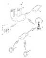
- FIG. 1is a simplified block diagram of an exemplary personal safety system 10 according to the present disclosure.
- the personal safety system 10includes a base telephone 12 monitoring and in communication with a plurality of wearable devices 14 .
- the base telephone 12is preferably a specialized mobile telephone that is capable of communicating (transmitting and receiving data) with a base station or eNodeB 16 (also known as a cell tower).
- the base station 16enables the base telephone 12 to have connectivity with remote monitors and emergency centers 18 (illustrated as servers 19 , laptop computer 20 , and mobile telephone 21 ).
- the remote monitormay be a monitoring service, friends, and/or family members.
- the base telephone 12is preferably a simplified mobile telephone that has a screen for displaying notifications and information, and dedicated function buttons for receiving user input.
- the display screenalso may be touch-sensitive to receive user input and commands.
- the base telephonemay incorporate functionality typically found in mobile telephones and smartphones.
- the base telephone 12may be programmable to store, in its memory, a number of telephone numbers of family members, friends, caregivers, and doctors that can be automatically dialed when needed or commanded by the user.
- the base telephone 12may also be implemented by a conventional mobile telephone equipped with a specialized personal safety app that encompasses the functions described herein.
- Examples of the base telephone 12include a cellular phone, a smart phone, a session initiation protocol (SIP) phone, a laptop, a personal digital assistant (PDA), or any other device equipped with a display and a user interface capable of communicating with the telecommunication network and/or the Internet.
- the base telephone 12is a 2G/3G/4G, CDMA, and/or LTE-capable device.
- the base telephone 12may also be referred to by those skilled in the art as a mobile station, a subscriber station, a mobile unit, a subscriber unit, a wireless unit, a remote unit, a mobile device, a wireless device, a wireless communications device, a mobile subscriber station, a mobile terminal, a wireless terminal, a remote terminal, a handset, a mobile client, a client, or some other suitable terminology.
- the base telephone 12may be implemented by a wireless telephone handset that communicates with a landline base.
- the base telephone 12may also be a combination communication device that can communicate via both wireless and landline telecommunication pathways.
- the wearable device 14is preferably worn by the user so that it may monitor the user's wellbeing and status. It can take the form of a ring, bracelet, pendant, brooch, belt buckle, etc. depending on the user's preference. Certain embodiments of the wearable device may further implement the ability to take vital measurements of the user, such as temperature, pulse rate, blood oxygen content, etc.
- the wearable device 14preferably includes a visual indicator such as an LED (preferably multi-colored LED to provide status information) and is capable of providing audio notification (pre-recorded sounds and messages) and haptic feedback to the user. Other forms of audio/visual/haptic feedback are contemplated herein.
- the base telephone 12 and wearable device 14are designed to carry on two-way communication and work together in close proximity. Ideally, the user would wear the wearable device 14 on her person, such as worn around her wrist like a bracelet or watch, for example.
- the base telephone 12is preferably carried in the user's pocket, purse, clipped-on to a belt, or otherwise positioned nearby.
- the two devicesfunction together to monitor the user's status, provide audio/visual/haptic notification to the user via the wearable device, and to provide additional information on the display screen of the base telephone to the user.
- the base telephonemay further incorporate other exterior visual indicators, such as multi-colored LEDs.
- the base telephoneis further used to transmit notification to remote monitors, family members, caregivers, and doctors 18 , for example, via the telecommunication network and/or the Internet.
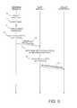
- FIG. 2is a simplified message flow diagram of an exemplary process for range notification according to the present disclosure.
- the system 10functions to ensure that the distance between the two devices does not exceed a predetermined threshold.
- the wearable device 14is typically operating in the low power mode (indicated by numeral 22 ) with the assumption that the wearable device 14 is within a nominal range of the base telephone 12 . Operating in the low power mode saves power usage and prolongs the operating time for the wearable device and the base telephone.
- the base telephone 12continually monitors transmissions from the wearable device 14 . Periodically, the wearable device 14 transmits a data packet or message to the base telephone 12 .
- the data messagemay include status data indicative of current system status, user status and measurements, and other information.
- the wearable device 14may use decreasing power to transmit the data packet/message to the base telephone 12 until bit errors and lost data packets occur to determine the minimum signal power needed for data transmission between the wearable device and the base telephone (indicated by numeral 24 ). When data transmission errors occur, the wearable device 14 increases the transmission power until the transmission errors are minimized or eliminated. In this way, the wearable device 14 may modulate power usage for power savings purposes.
- the wearable device 14further determines when the distance between the devices is near a limit (indicated by numeral 26 ).
- the useris notified when the distance between the base telephone and the wearable device exceeds or approached the limit (indicated by numeral 28 ) by audio/visual/haptic means. Because the base telephone is used to display messages and other data on its screen, the system reminds the user to keep the base telephone close to the user for easy access. The base telephone also displays the range notification on its screen (indicated by numeral 29 ).
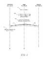
- FIG. 3is a simplified message flow diagram of an exemplary process for emergency response and notification according to the present disclosure.
- the wearable device 14is typically operating in the low power mode (indicated by numeral 30 ) with the assumption that the wearable device 14 is within a nominal range of the base telephone 12 . As described above, the range and operating transmission power of the wearable and/or base telephone is continually monitored and modulated in order to save power consumption.
- the wearable device 14determines that a conspicuously marked emergency/panic button has been activated or pushed (indicated by numeral 32 ).
- the wearable device 14preferably includes a dedicated button that may be used to initiate an emergency operating status. In response, the wearable device enters high power mode (indicated by numeral 34 ).
- the wearable devicemay optionally provide audio/visual/haptic feedback when the user pushes the emergency button to indicate that it has received the emergency input from the user.
- the wearable devicealso sends an appropriate notification to the base telephone (indicated by numeral 36 ), which in turn transmits the emergency status to a remote monitor (indicated by numeral 38 ).
- the base telephone 12sends back an acknowledgement message to the wearable device (indicated by numeral 40 ).
- the display screen on the base telephonealso reflects the emergency status (indicated by numeral 42 ).
- the wearable devicemay indicate to the user via audio/visual/haptic feedback that the emergency status has now been transmitted remotely and that help will be forthcoming.
- the foregoing emergency processmay also be automatically activated when the wearable device detects a fall (by its internal accelerometer), a weak or irregular pulse (by its internal heart rate monitor), low blood oxygen level (by its internal pulse oximeter), and any other less than optimal condition of the user.
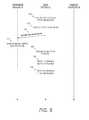
- FIG. 4is a simplified message flow diagram of an exemplary process for low battery status notification according to the present disclosure.
- the wearable device 14periodically performs a status check and sends status data to the base telephone (indicated by numerals 50 and 51 ). As a part of the status check, the wearable device may perform basic diagnostics on its operating parameters such as battery level, etc.
- the base telephonereceives the status data and determines that the wearable is in good operating status (indicated by numeral 52 ), and may reflect this status on its display and/or other exterior visual indicators (indicated by numeral 54 ).
- the base telephonethen sends back to the wearable device an acknowledgement message (indicated by numeral 56 ).
- the wearable device 14performs another status check and sends its status data to the base telephone 12 .
- the base telephonereceives the status data and determines that the wearable device is experiencing a low battery condition (indicated by numeral 62 ).
- the base telephonedisplays this low battery status on its screen (indicated by numeral 64 ).
- the base telephonefurther sends a low battery notification message to the wearable device as well as the remote monitor (indicated by numerals 66 and 68 ).
- the low battery notificationmay be sent to the remote monitor after a predetermined time has elapsed or the battery level drops below an even lower threshold.
- the wearable deviceprovides audio/visual/haptic feedback to the user (indicated by numeral 69 ), so that the user may view the screen on the base telephone and recognize the low battery status.
- the wearable devicemay also include an exterior visual indicator such as a lit or blinking red LED to convey to the user the low battery status. The user may then recharge or replace the battery in the wearable device.
- FIG. 5is a simplified message flow diagram of an exemplary process for inactivity status notification according to the present disclosure.
- the wearable device 14detects that the user is inactive and starts a timer (indicated by numerals 70 and 71 ).
- the inactivity detectionmay be measured by an accelerometer, for example.
- the recognition of inactivitymay initiate measuring the user's pulse rate and blood oxygen content, and making the measurements available to the base telephone for analysis and/or remote transmission.
- the timeris restarted when the wearable device detects movement in the user.
- the wearable deviceIf the timer eventually exceeds a predetermined limit or threshold, then the wearable device generates an audio/visual/haptic notification (indicated by numeral 72 ).
- the purpose of the notificationmay be to wake up the user, who may be a worker that may have dozed off on the job, or a user that may have become unconscious.
- the inactivity statusis transmitted by the wearable device to the base telephone (indicated by numeral 76 ).
- the base telephonedetermines from the notification that the user is inactive, and may generate its own audio/visual/haptic notification (indicated by numerals 78 and 80 ). Further, the base telephone may send an inactivity notification to the remote monitor (indicated by numeral 82 ).
- FIG. 6is a simplified message flow diagram of an exemplary process for fall notification according to the present disclosure.
- An accelerometer in the wearable device 14may detect a fall or another trauma experienced by the user (indicated by numeral 90 ).
- the wearable deviceimmediately sends a fall notification to the base telephone (indicated by numeral 91 ).
- the base telephone 12receives the fall notification message and is informed that the user may have experienced a fall, and may display this as a status on its screen (indicated by numerals 92 and 94 ).
- the base telephonesends an acknowledgement message back to the wearable device, and additionally sends a fall notification to the remote monitor (indicated by numerals 96 and 98 ).
- the wearable devicemay generate an audio/visual/haptic notification to let the user know that help is on the way (indicated by numeral 99 ).
- FIG. 7is a simplified message flow diagram of an exemplary process for base telephone low battery notification according to the present disclosure.
- the base telephonemay perform a status check of its own operational parameters (indicated by numeral 100 ). As a part of its status check, it determines that its own battery charge is below a certain threshold (indicated by numeral 102 ). In response, the base telephone displays the low battery status on its screen or via an exterior visual indicator (indicated by numeral 104 ). The base telephone further sends a low battery notification to the wearable device to notify the user, and another low battery notification to the remote monitor (indicated by numerals 106 and 108 ). In response, the wearable device generates an audio/visual/haptic notification to notify the user of a condition that needs attention.
- FIG. 8is a simplified message flow diagram of an exemplary process for calendar event notification according to the present disclosure.
- the base telephonemay store calendar events such as doctors' appointments, medication reminders, prescription medicine refills, and social engagements in its memory.
- a remote server 19may store these calendar events and send a notification to the base telephone 12 at the appropriate reminder time.
- the base telephonegenerates a calendar event notification when a stored event has an associated scheduled reminder (indicated by numeral 110 ).
- the base telephonedisplays information related to the calendar event on its screen and sends a notification to the wearable device (indicated by numerals 112 and 114 ).
- the wearable devicegenerates an audio/visual/haptic notification to alert the user (indicated by numeral 116 ), so that the user may view details of the calendar event on the screen of the base telephone 12 .
- the usermay optionally push a feedback/acknowledgement button on the base telephone 12 to indicate acknowledgement of receiving the calendar event notification (indicated by numeral 118 ).
- the base telephonemay transmit the acknowledgement to the remote server so that the remote monitor knows that the user has received the calendar event notification.
- the base telephone 12may be customized to automatically initiate the text-to-speech function and audibly announce the calendar event.
- the base telephone 12may announce, “Doctor appointment scheduled today at nine-thirty,” along with a message from a caregiver recorded when the appointment was entered into the system, “Mom, I will pick you up today at your house at nine. We can go to lunch after your appointment.”
- the base telephone 12is also capable of providing other forms of notification to the wearable device 14 in a similar manner. For example, an incoming call on the base telephone may cause it to ring, as well as send a call notification to the wearable device. The wearable device may in turn provide audio/visual/haptic notification to alert the user.
- the base telephonemay similarly include the capability to recognize and provide notification for door bells, and other situations where the user's attention is needed.
- FIG. 9a simplified message flow diagram of an exemplary process for text message notification according to the present disclosure.
- the base telephonemay receive a text message, audio message, multimedia message, or another form of text communication intended for the user.
- the base telephonegenerates a text message event notification and displays the text message on its screen (indicated by numerals 120 and 122 ).
- the base telephonethen sends a notification message to the wearable device (indicated by numeral 124 ).
- the wearable devicegenerates an audio/visual/haptic notification to alert the user (indicated by numeral 126 ), so that the user may view the text message on the screen of the base telephone.
- the usermay optionally push a feedback or acknowledgement button on the base telephone to indicate acknowledgement of receiving the calendar event notification (indicated by numeral 128 ).
- the base telephonemay transmit the acknowledgement to the remote server so that the remote monitor knows that the user has heard/seen the message.
- the usermay instruct the base telephone to verbalize the text message with its text-to-speech functionality (indicated by numerals 130 and 132 ).
- the usermay push a dedicated text-to-speech button or enter the command via another form of user interface.
- the data communication to and from the wearable deviceinclude unique identifiers that are associated with particular users.
- the base telephone and the wearable devicescan carry on two-way communications in a broadcast manner and in a targeted way specific to a particular user.
- FIG. 10is a simplified block diagram of an exemplary specialized device 140 that may implement the base telephone 12 and/or the wearable device 14 for carrying out the afore-described methods according to the present disclosure.
- the device 140may include a bus 142 or electrical pathway that interconnects a processor 144 , a memory 146 , a communication interface 148 , an input device 150 , and an output device 152 .
- the bus 142enables communication among the various components of device 140 .
- the processor 144may include one or more processing units or microprocessors that interpret and execute coded instructions. In other implementations, the processor 144 may be implemented by or include one or more application-specific integrated circuits (ASICs), field programmable gate arrays (FPGAs), or the like.
- ASICsapplication-specific integrated circuits
- FPGAsfield programmable gate arrays
- the memory 146may include a random access memory (RAM) or another type of dynamic storage device that stores information and instructions for execution by the processor 104 .
- the memory 146may also include a read-only memory (ROM) or another type of static storage device that stores static information and instructions for the processor 144 .
- the memory 146may further include other types of magnetic or optical recording medium and its corresponding drive for storing information and/or instructions.
- the term “memory”is broadly to include registers, buffers, and other data constructs configured to hold data.
- the communication interface 148may include protocol stacks for processing data transmitted via a data protocol now know or to be developed.
- the communication interface 148may include multi-band antenna and transceiver devices that enables the device 140 to communicate via across wide bands of radio frequency with other devices and/or systems.
- the communication interface 138may further include interfaces, ports, or connectors to other devices.
- the input 150may include one or more devices that permit a user to enter commands and data into the device 140 , such as button(s), a keypad, a keyboard, a stylus, a touch-sensitive pad or screen, a microphone, one or more biometric mechanisms, and the like.
- the inputmay further include a microphone in the case of the base telephone.
- the output 152may include one or more devices that outputs information to the operator, such as LED(s), a display screen, a speaker, etc.
- the device 140may perform certain operations in response to the processor 144 executing custom and specialized software instructions contained in a computer-readable medium, such as memory 146 .
- a computer-readable mediummay be defined as a physical or logical memory device.
- a logical memory devicemay include memory space within a single physical memory device or spread across multiple physical memory devices.
- the custom software instructionsmay be downloaded from the Internet, read into memory 146 from another computer-readable medium, or from another device via a communication interface 148 .
- the specialized software instructions contained in the memory 146may cause the processor 144 to perform specialized processes described herein.
- hardwired circuitrymay be used in place of or in combination with software instructions to implement processes described herein. Thus, implementations described herein are not limited to any specifically required combination of hardware circuitry and software.
- the wearable devicecan remain a simple and small device that can be easily worn by the user.
- the base telephonecan push notification to the wearable device, and provide information on its display screen.
- the wearable deviceincorporates simple devices that can provide audio/visual/haptic notification to the user, and prompts the user to look on the base telephone's display for information on the triggering event, such as an incoming call or text message, low battery, out-of-range, scheduled appointment, etc.
- the wearable device 14may further incorporate specialized instruments such as accelerometer, oximeter, thermometer, and other devices that can provide more specific measurement data concerning the wellbeing of the user.
- specialized instrumentssuch as accelerometer, oximeter, thermometer, and other devices that can provide more specific measurement data concerning the wellbeing of the user.
- the term “device”may be used to refer a specialized physical circuit or collection of hardware components, a specially-programmed logical code module, functionality, and/or a combination of hardware and software entities.
Landscapes
- Health & Medical Sciences (AREA)
- Emergency Management (AREA)
- Business, Economics & Management (AREA)
- Engineering & Computer Science (AREA)
- General Physics & Mathematics (AREA)
- Physics & Mathematics (AREA)
- General Health & Medical Sciences (AREA)
- Gerontology & Geriatric Medicine (AREA)
- Signal Processing (AREA)
- Computer Networks & Wireless Communication (AREA)
- Social Psychology (AREA)
- Psychology (AREA)
- Psychiatry (AREA)
- Cardiology (AREA)
- Pulmonology (AREA)
- Physiology (AREA)
- Physical Education & Sports Medicine (AREA)
- Heart & Thoracic Surgery (AREA)
- Biophysics (AREA)
- Life Sciences & Earth Sciences (AREA)
- Computer Security & Cryptography (AREA)
- Environmental & Geological Engineering (AREA)
- Public Health (AREA)
- Telephonic Communication Services (AREA)
- Telephone Function (AREA)
Abstract
Description
Claims (36)
Priority Applications (1)
| Application Number | Priority Date | Filing Date | Title |
|---|---|---|---|
| US14/667,970US9443410B1 (en) | 2015-03-25 | 2015-03-25 | Personal safety response system and method |
Applications Claiming Priority (1)
| Application Number | Priority Date | Filing Date | Title |
|---|---|---|---|
| US14/667,970US9443410B1 (en) | 2015-03-25 | 2015-03-25 | Personal safety response system and method |
Publications (2)
| Publication Number | Publication Date |
|---|---|
| US9443410B1true US9443410B1 (en) | 2016-09-13 |
| US20160284189A1 US20160284189A1 (en) | 2016-09-29 |
Family
ID=56881384
Family Applications (1)
| Application Number | Title | Priority Date | Filing Date |
|---|---|---|---|
| US14/667,970Active - ReinstatedUS9443410B1 (en) | 2015-03-25 | 2015-03-25 | Personal safety response system and method |
Country Status (1)
| Country | Link |
|---|---|
| US (1) | US9443410B1 (en) |
Cited By (24)
| Publication number | Priority date | Publication date | Assignee | Title |
|---|---|---|---|---|
| US20170332330A1 (en)* | 2016-05-13 | 2017-11-16 | Verizon Patent And Licensing Inc. | POWER MANAGEMENT OF AN IoT TRACKER |
| US9850957B2 (en)* | 2015-09-30 | 2017-12-26 | Apple Inc. | Electronic device with haptic actuation stiction release after non-movement threshold time period and related methods |
| US20180262490A1 (en)* | 2017-03-13 | 2018-09-13 | At&T Intellectual Property I, L.P. | Biometrics hub for processing biometrics data for authorized remote devices |
| US10111079B2 (en) | 2016-07-06 | 2018-10-23 | Katana Safety, Inc. | Mobile device accessory with separate component for control or alert |
| US10181331B2 (en) | 2017-02-16 | 2019-01-15 | Neosensory, Inc. | Method and system for transforming language inputs into haptic outputs |
| US10198076B2 (en)* | 2016-09-06 | 2019-02-05 | Neosensory, Inc. | Method and system for providing adjunct sensory information to a user |
| US10373450B2 (en)* | 2015-06-26 | 2019-08-06 | Zuko MANDLAKAZI | Alert device, system and method |
| US10372212B2 (en)* | 2015-05-29 | 2019-08-06 | Google Llc | Techniques for simulated physical interaction between users via their mobile computing devices |
| CN110476406A (en)* | 2017-03-29 | 2019-11-19 | 夏普株式会社 | Information processing system |
| US10659946B2 (en) | 2016-07-06 | 2020-05-19 | Katana Safety, Inc. | Mobile device attachment with user activated alarm |
| US10699538B2 (en) | 2016-07-27 | 2020-06-30 | Neosensory, Inc. | Method and system for determining and providing sensory experiences |
| US10744058B2 (en) | 2017-04-20 | 2020-08-18 | Neosensory, Inc. | Method and system for providing information to a user |
| US11079854B2 (en) | 2020-01-07 | 2021-08-03 | Neosensory, Inc. | Method and system for haptic stimulation |
| US11087609B2 (en)* | 2017-11-21 | 2021-08-10 | Tric It S.R.L. | Emergency management method comprising a device for emergency calls |
| US11100767B1 (en)* | 2019-03-26 | 2021-08-24 | Halo Wearables, Llc | Group management for electronic devices |
| US11122388B2 (en) | 2019-04-11 | 2021-09-14 | Compology, Inc. | Method and system for container location analysis |
| US20220028248A1 (en)* | 2018-12-07 | 2022-01-27 | 3M Innovative Properties Company | Adaptive notification system based on contextual information |
| US11467667B2 (en) | 2019-09-25 | 2022-10-11 | Neosensory, Inc. | System and method for haptic stimulation |
| US11467668B2 (en) | 2019-10-21 | 2022-10-11 | Neosensory, Inc. | System and method for representing virtual object information with haptic stimulation |
| US11497675B2 (en) | 2020-10-23 | 2022-11-15 | Neosensory, Inc. | Method and system for multimodal stimulation |
| US11610185B2 (en) | 2013-03-15 | 2023-03-21 | Compology Llc | System and method for waste management |
| US11862147B2 (en) | 2021-08-13 | 2024-01-02 | Neosensory, Inc. | Method and system for enhancing the intelligibility of information for a user |
| US11995240B2 (en) | 2021-11-16 | 2024-05-28 | Neosensory, Inc. | Method and system for conveying digital texture information to a user |
| US12254403B2 (en) | 2018-12-12 | 2025-03-18 | Compology Llc | Method and system for fill level determination |
Families Citing this family (4)
| Publication number | Priority date | Publication date | Assignee | Title |
|---|---|---|---|---|
| ES2663141A1 (en)* | 2017-07-17 | 2018-04-11 | Antonio PEDROCHE PALOMAR | Road Safety Device (Machine-translation by Google Translate, not legally binding) |
| EP3441957A1 (en) | 2017-08-07 | 2019-02-13 | Swiss Innovation Lab AG | Alerting device and system |
| GB2578755A (en)* | 2018-11-07 | 2020-05-27 | Robert Ghosh Indrajit | A telephony device and associated system |
| JP6841353B2 (en)* | 2020-02-05 | 2021-03-10 | カシオ計算機株式会社 | Information notification method, information notification device, and program |
Citations (18)
| Publication number | Priority date | Publication date | Assignee | Title |
|---|---|---|---|---|
| US5265151A (en)* | 1991-07-26 | 1993-11-23 | General Datacomm, Inc. | Method of improving modem performance by controlling transmitted power of modem, and modem implementing the same |
| US20020027946A1 (en)* | 1995-06-30 | 2002-03-07 | Ozluturk Fatih M. | Method for adaptive reverse power control for spread-spectrum communications |
| US6639516B1 (en)* | 2002-05-14 | 2003-10-28 | Shaun Michael Copley | Personal tracking device |
| US20040203362A1 (en)* | 2002-04-02 | 2004-10-14 | Ganesh Pattabiraman | System and method for bluetooth paging with transmit power reduced according to channel metrics measured during inquiry process |
| US6847295B1 (en)* | 2004-04-08 | 2005-01-25 | Vernice Doyle Taliaferro | Anti-abduction system and method |
| US20050136955A1 (en)* | 2003-12-23 | 2005-06-23 | Mumick Inderpal S. | Techniques for combining voice with wireless text short message services |
| EP1924069A1 (en) | 2006-11-14 | 2008-05-21 | Promotion and Display Technology Limited | Telecommunication device for transmitting an emergency message |
| US8116724B2 (en) | 2009-05-11 | 2012-02-14 | Vocare, Inc. | System containing location-based personal emergency response device |
| US8249547B1 (en) | 2011-06-16 | 2012-08-21 | Albert Fellner | Emergency alert device with mobile phone |
| US20130244633A1 (en)* | 2012-03-16 | 2013-09-19 | Qualcomm Incorporated | Systems and methods for providing notifications |
| US8548422B2 (en)* | 2008-03-05 | 2013-10-01 | Nevin C. Jenkins | Versatile personal medical emergency communication system |
| US8680991B2 (en)* | 2006-06-30 | 2014-03-25 | Bao Tran | Personal emergency response appliance |
| WO2014124497A1 (en) | 2013-02-14 | 2014-08-21 | Harry Louis Platt | A portable assistance request device |
| US8826348B2 (en)* | 2006-12-04 | 2014-09-02 | Samsung Electronics Co., Ltd. | System and method for wireless communication of uncompressed video having a relay device for power saving |
| US20140278220A1 (en)* | 2012-06-22 | 2014-09-18 | Fitbit, Inc. | Fitness monitoring device with altimeter |
| US20140334271A1 (en)* | 2013-05-07 | 2014-11-13 | Lg Electronics Inc. | Smart watch and method for controlling the same |
| US20150065095A1 (en)* | 2013-08-28 | 2015-03-05 | Samsung Electronics Co., Ltd. | Method for transmitting notification information and electronic device thereof |
| US20160049798A1 (en)* | 2013-04-15 | 2016-02-18 | Nissan Motor Co., Ltd. | Contactless power supplying system |
- 2015
- 2015-03-25USUS14/667,970patent/US9443410B1/enactiveActive - Reinstated
Patent Citations (18)
| Publication number | Priority date | Publication date | Assignee | Title |
|---|---|---|---|---|
| US5265151A (en)* | 1991-07-26 | 1993-11-23 | General Datacomm, Inc. | Method of improving modem performance by controlling transmitted power of modem, and modem implementing the same |
| US20020027946A1 (en)* | 1995-06-30 | 2002-03-07 | Ozluturk Fatih M. | Method for adaptive reverse power control for spread-spectrum communications |
| US20040203362A1 (en)* | 2002-04-02 | 2004-10-14 | Ganesh Pattabiraman | System and method for bluetooth paging with transmit power reduced according to channel metrics measured during inquiry process |
| US6639516B1 (en)* | 2002-05-14 | 2003-10-28 | Shaun Michael Copley | Personal tracking device |
| US20050136955A1 (en)* | 2003-12-23 | 2005-06-23 | Mumick Inderpal S. | Techniques for combining voice with wireless text short message services |
| US6847295B1 (en)* | 2004-04-08 | 2005-01-25 | Vernice Doyle Taliaferro | Anti-abduction system and method |
| US8680991B2 (en)* | 2006-06-30 | 2014-03-25 | Bao Tran | Personal emergency response appliance |
| EP1924069A1 (en) | 2006-11-14 | 2008-05-21 | Promotion and Display Technology Limited | Telecommunication device for transmitting an emergency message |
| US8826348B2 (en)* | 2006-12-04 | 2014-09-02 | Samsung Electronics Co., Ltd. | System and method for wireless communication of uncompressed video having a relay device for power saving |
| US8548422B2 (en)* | 2008-03-05 | 2013-10-01 | Nevin C. Jenkins | Versatile personal medical emergency communication system |
| US8116724B2 (en) | 2009-05-11 | 2012-02-14 | Vocare, Inc. | System containing location-based personal emergency response device |
| US8249547B1 (en) | 2011-06-16 | 2012-08-21 | Albert Fellner | Emergency alert device with mobile phone |
| US20130244633A1 (en)* | 2012-03-16 | 2013-09-19 | Qualcomm Incorporated | Systems and methods for providing notifications |
| US20140278220A1 (en)* | 2012-06-22 | 2014-09-18 | Fitbit, Inc. | Fitness monitoring device with altimeter |
| WO2014124497A1 (en) | 2013-02-14 | 2014-08-21 | Harry Louis Platt | A portable assistance request device |
| US20160049798A1 (en)* | 2013-04-15 | 2016-02-18 | Nissan Motor Co., Ltd. | Contactless power supplying system |
| US20140334271A1 (en)* | 2013-05-07 | 2014-11-13 | Lg Electronics Inc. | Smart watch and method for controlling the same |
| US20150065095A1 (en)* | 2013-08-28 | 2015-03-05 | Samsung Electronics Co., Ltd. | Method for transmitting notification information and electronic device thereof |
Cited By (52)
| Publication number | Priority date | Publication date | Assignee | Title |
|---|---|---|---|---|
| US12067536B2 (en) | 2013-03-15 | 2024-08-20 | Compology Llc | System and method for waste management |
| US11610185B2 (en) | 2013-03-15 | 2023-03-21 | Compology Llc | System and method for waste management |
| US10372212B2 (en)* | 2015-05-29 | 2019-08-06 | Google Llc | Techniques for simulated physical interaction between users via their mobile computing devices |
| US10901512B1 (en)* | 2015-05-29 | 2021-01-26 | Google Llc | Techniques for simulated physical interaction between users via their mobile computing devices |
| US10373450B2 (en)* | 2015-06-26 | 2019-08-06 | Zuko MANDLAKAZI | Alert device, system and method |
| US9850957B2 (en)* | 2015-09-30 | 2017-12-26 | Apple Inc. | Electronic device with haptic actuation stiction release after non-movement threshold time period and related methods |
| US11452044B2 (en)* | 2016-05-13 | 2022-09-20 | Verizon Patent And Licensing Inc. | Power management of an IoT tracker |
| US20170332330A1 (en)* | 2016-05-13 | 2017-11-16 | Verizon Patent And Licensing Inc. | POWER MANAGEMENT OF AN IoT TRACKER |
| US10785723B2 (en)* | 2016-05-13 | 2020-09-22 | Verizon Patent And Licensing Inc. | Power management of an IoT tracker |
| USD941171S1 (en) | 2016-07-06 | 2022-01-18 | Katana Safety, Inc. | Mobile phone personal security accessory |
| US10462641B2 (en) | 2016-07-06 | 2019-10-29 | Katana Safety, Inc. | Mobile device accessory with separate component for control or alert |
| USD956763S1 (en) | 2016-07-06 | 2022-07-05 | Katana Safety, Inc. | Mobile device accessory |
| US11019475B2 (en) | 2016-07-06 | 2021-05-25 | Katana Safety, Inc. | Mobile device attachment with user activated alarm |
| US10659946B2 (en) | 2016-07-06 | 2020-05-19 | Katana Safety, Inc. | Mobile device attachment with user activated alarm |
| USD853400S1 (en) | 2016-07-06 | 2019-07-09 | Katana Safety, Inc. | Mobile device accessory |
| US11234112B2 (en) | 2016-07-06 | 2022-01-25 | Katana Safety, Inc. | Mobile device with user activated alarm |
| USD956764S1 (en) | 2016-07-06 | 2022-07-05 | Katana Safety, Inc. | Mobile device accessory |
| USD941172S1 (en) | 2016-07-06 | 2022-01-18 | Katana Safety, Inc. | Mobile phone personal security accessory |
| US10111079B2 (en) | 2016-07-06 | 2018-10-23 | Katana Safety, Inc. | Mobile device accessory with separate component for control or alert |
| US10699538B2 (en) | 2016-07-27 | 2020-06-30 | Neosensory, Inc. | Method and system for determining and providing sensory experiences |
| US20190121439A1 (en)* | 2016-09-06 | 2019-04-25 | Neosensory, Inc. | Method and system for providing adjunct sensory information to a user |
| US10642362B2 (en)* | 2016-09-06 | 2020-05-05 | Neosensory, Inc. | Method and system for providing adjunct sensory information to a user |
| US11644900B2 (en)* | 2016-09-06 | 2023-05-09 | Neosensory, Inc. | Method and system for providing adjunct sensory information to a user |
| US11079851B2 (en)* | 2016-09-06 | 2021-08-03 | Neosensory, Inc. | Method and system for providing adjunct sensory information to a user |
| US20210318757A1 (en)* | 2016-09-06 | 2021-10-14 | Neosensory, Inc. | Method and system for providing adjunct sensory information to a user |
| US10198076B2 (en)* | 2016-09-06 | 2019-02-05 | Neosensory, Inc. | Method and system for providing adjunct sensory information to a user |
| US10181331B2 (en) | 2017-02-16 | 2019-01-15 | Neosensory, Inc. | Method and system for transforming language inputs into haptic outputs |
| US11606355B2 (en)* | 2017-03-13 | 2023-03-14 | At&T Intellectual Property I, L.P. | Biometrics hub for processing biometrics data for authorized remote devices |
| US20210014223A1 (en)* | 2017-03-13 | 2021-01-14 | At&T Intellectual Property I, L.P. | Biometrics hub for processing biometrics data for authorized remote devices |
| US20180262490A1 (en)* | 2017-03-13 | 2018-09-13 | At&T Intellectual Property I, L.P. | Biometrics hub for processing biometrics data for authorized remote devices |
| US10791113B2 (en)* | 2017-03-13 | 2020-09-29 | At&T Intellectual Property I, L.P. | Biometrics hub for processing biometrics data for authorized remote devices |
| CN110476406A (en)* | 2017-03-29 | 2019-11-19 | 夏普株式会社 | Information processing system |
| US10744058B2 (en) | 2017-04-20 | 2020-08-18 | Neosensory, Inc. | Method and system for providing information to a user |
| US11207236B2 (en) | 2017-04-20 | 2021-12-28 | Neosensory, Inc. | Method and system for providing information to a user |
| US10993872B2 (en)* | 2017-04-20 | 2021-05-04 | Neosensory, Inc. | Method and system for providing information to a user |
| US11660246B2 (en) | 2017-04-20 | 2023-05-30 | Neosensory, Inc. | Method and system for providing information to a user |
| US11087609B2 (en)* | 2017-11-21 | 2021-08-10 | Tric It S.R.L. | Emergency management method comprising a device for emergency calls |
| US20220028248A1 (en)* | 2018-12-07 | 2022-01-27 | 3M Innovative Properties Company | Adaptive notification system based on contextual information |
| US12183184B2 (en)* | 2018-12-07 | 2024-12-31 | 3M Innovative Properties Company | Adaptive notification system based on contextual information |
| US12254403B2 (en) | 2018-12-12 | 2025-03-18 | Compology Llc | Method and system for fill level determination |
| US11100767B1 (en)* | 2019-03-26 | 2021-08-24 | Halo Wearables, Llc | Group management for electronic devices |
| US11887467B1 (en)* | 2019-03-26 | 2024-01-30 | Tula Health, Inc. | Group management for electronic devices |
| US11122388B2 (en) | 2019-04-11 | 2021-09-14 | Compology, Inc. | Method and system for container location analysis |
| US11467667B2 (en) | 2019-09-25 | 2022-10-11 | Neosensory, Inc. | System and method for haptic stimulation |
| US11467668B2 (en) | 2019-10-21 | 2022-10-11 | Neosensory, Inc. | System and method for representing virtual object information with haptic stimulation |
| US12001608B2 (en) | 2019-10-21 | 2024-06-04 | Neosensory, Inc. | System and method for representing virtual object information with haptic stimulation |
| US11614802B2 (en) | 2020-01-07 | 2023-03-28 | Neosensory, Inc. | Method and system for haptic stimulation |
| US11079854B2 (en) | 2020-01-07 | 2021-08-03 | Neosensory, Inc. | Method and system for haptic stimulation |
| US11877975B2 (en) | 2020-10-23 | 2024-01-23 | Neosensory, Inc. | Method and system for multimodal stimulation |
| US11497675B2 (en) | 2020-10-23 | 2022-11-15 | Neosensory, Inc. | Method and system for multimodal stimulation |
| US11862147B2 (en) | 2021-08-13 | 2024-01-02 | Neosensory, Inc. | Method and system for enhancing the intelligibility of information for a user |
| US11995240B2 (en) | 2021-11-16 | 2024-05-28 | Neosensory, Inc. | Method and system for conveying digital texture information to a user |
Also Published As
| Publication number | Publication date |
|---|---|
| US20160284189A1 (en) | 2016-09-29 |
Similar Documents
| Publication | Publication Date | Title |
|---|---|---|
| US9443410B1 (en) | Personal safety response system and method | |
| US12214214B2 (en) | Remote medical device alarm | |
| US8487771B2 (en) | Personal health management device | |
| EP2023800B1 (en) | Communication system for monitoring the health status of a patient, communication device and method | |
| US8803688B2 (en) | System and method responsive to an event detected at a glucose monitoring device | |
| US9734690B2 (en) | System and method for activity monitoring and fall detection | |
| EP3127378B1 (en) | Wearable apparatus and network for communication therewith | |
| US7400257B2 (en) | Vital signals and glucose monitoring personal wireless system | |
| US8423000B2 (en) | Guardian system for a cognitively-impaired individual | |
| US20090243878A1 (en) | Radio frequency transmitter and receiver system and apparatus | |
| JP4706040B2 (en) | Life crisis emergency call system | |
| US20150173674A1 (en) | Detecting and communicating health conditions | |
| US20110163880A1 (en) | System and method responsive to an alarm event detected at an insulin delivery device | |
| US20220398914A1 (en) | Wearable Device and System for Tracking and Sharing Vital Signs and Location of User | |
| WO2010144626A1 (en) | Personal monitoring apparatus, system and method | |
| JP3131971U (en) | Combination of mobile phone and mobile communication terminal capable of bidirectional communication with mobile phone | |
| JP6664919B2 (en) | Mobile monitoring terminal and program | |
| KR20020024083A (en) | Mobile health checker and method for checking health | |
| CN211834338U (en) | Intelligent wearable device | |
| JP2007054241A (en) | Mobile terminal device | |
| JP2023117260A (en) | Lifesaving rescue support system, information processing method, and application program | |
| KR20170060211A (en) | A method for transmitting of users emergency information and alarming sleep time | |
| KR100386702B1 (en) | System for monitoring a first-aid Patient | |
| KR200271283Y1 (en) | Mobile health checker | |
| KR101251472B1 (en) | Terminal using wireless pager network |
Legal Events
| Date | Code | Title | Description |
|---|---|---|---|
| AS | Assignment | Owner name:ANELTO, INC., TEXAS Free format text:ASSIGNMENT OF ASSIGNORS INTEREST;ASSIGNOR:CONSTIEN, SCOTT D.;REEL/FRAME:035283/0562 Effective date:20150326 | |
| STCF | Information on status: patent grant | Free format text:PATENTED CASE | |
| FEPP | Fee payment procedure | Free format text:MAINTENANCE FEE REMINDER MAILED (ORIGINAL EVENT CODE: REM.); ENTITY STATUS OF PATENT OWNER: SMALL ENTITY | |
| LAPS | Lapse for failure to pay maintenance fees | Free format text:PATENT EXPIRED FOR FAILURE TO PAY MAINTENANCE FEES (ORIGINAL EVENT CODE: EXP.); ENTITY STATUS OF PATENT OWNER: SMALL ENTITY | |
| STCH | Information on status: patent discontinuation | Free format text:PATENT EXPIRED DUE TO NONPAYMENT OF MAINTENANCE FEES UNDER 37 CFR 1.362 | |
| FP | Lapsed due to failure to pay maintenance fee | Effective date:20200913 | |
| FEPP | Fee payment procedure | Free format text:SURCHARGE, PETITION TO ACCEPT PYMT AFTER EXP, UNINTENTIONAL. (ORIGINAL EVENT CODE: M2558); ENTITY STATUS OF PATENT OWNER: SMALL ENTITY Free format text:PETITION RELATED TO MAINTENANCE FEES GRANTED (ORIGINAL EVENT CODE: PMFG); ENTITY STATUS OF PATENT OWNER: SMALL ENTITY Free format text:PETITION RELATED TO MAINTENANCE FEES FILED (ORIGINAL EVENT CODE: PMFP); ENTITY STATUS OF PATENT OWNER: SMALL ENTITY | |
| MAFP | Maintenance fee payment | Free format text:PAYMENT OF MAINTENANCE FEE, 4TH YR, SMALL ENTITY (ORIGINAL EVENT CODE: M2551); ENTITY STATUS OF PATENT OWNER: SMALL ENTITY Year of fee payment:4 | |
| PRDP | Patent reinstated due to the acceptance of a late maintenance fee | Effective date:20210628 | |
| STCF | Information on status: patent grant | Free format text:PATENTED CASE | |
| AS | Assignment | Owner name:CRESTLINE DIRECT FINANCE, L.P., TEXAS Free format text:SECURITY INTEREST;ASSIGNORS:ANELTO, INC.;INSTANT CARE, INC.;REEL/FRAME:059888/0071 Effective date:20220506 | |
| MAFP | Maintenance fee payment | Free format text:PAYMENT OF MAINTENANCE FEE, 8TH YR, SMALL ENTITY (ORIGINAL EVENT CODE: M2552); ENTITY STATUS OF PATENT OWNER: SMALL ENTITY Year of fee payment:8 | |
| AS | Assignment | Owner name:TCW ASSET MANAGEMENT COMPANY LLC, AS COLLATERAL AGENT, MASSACHUSETTS Free format text:SECURITY INTEREST;ASSIGNORS:LIFELINE SYSTEMS COMPANY;ANELTO, INC.;100PLUS, INC.;AND OTHERS;REEL/FRAME:069164/0414 Effective date:20241011 | |
| AS | Assignment | Owner name:INSTANT CARE, INC., CALIFORNIA Free format text:RELEASE BY SECURED PARTY;ASSIGNOR:CRESTLINE DIRECT FINANCE, L.P.;REEL/FRAME:069045/0956 Effective date:20241011 Owner name:ANELTO, INC., TEXAS Free format text:RELEASE BY SECURED PARTY;ASSIGNOR:CRESTLINE DIRECT FINANCE, L.P.;REEL/FRAME:069045/0956 Effective date:20241011 |