US9443142B2 - Vision-based system for dynamic weather detection - Google Patents
Vision-based system for dynamic weather detectionDownload PDFInfo
- Publication number
- US9443142B2 US9443142B2US14/339,891US201414339891AUS9443142B2US 9443142 B2US9443142 B2US 9443142B2US 201414339891 AUS201414339891 AUS 201414339891AUS 9443142 B2US9443142 B2US 9443142B2
- Authority
- US
- United States
- Prior art keywords
- image
- scene
- region
- rain
- patches
- Prior art date
- Legal status (The legal status is an assumption and is not a legal conclusion. Google has not performed a legal analysis and makes no representation as to the accuracy of the status listed.)
- Active, expires
Links
Images


Classifications
- G06K9/00624—
- G—PHYSICS
- G06—COMPUTING OR CALCULATING; COUNTING
- G06V—IMAGE OR VIDEO RECOGNITION OR UNDERSTANDING
- G06V20/00—Scenes; Scene-specific elements
- G06K9/00711—
- G06T7/0075—
- G06T7/0081—
- G—PHYSICS
- G06—COMPUTING OR CALCULATING; COUNTING
- G06T—IMAGE DATA PROCESSING OR GENERATION, IN GENERAL
- G06T7/00—Image analysis
- G06T7/10—Segmentation; Edge detection
- G06T7/11—Region-based segmentation
- G—PHYSICS
- G06—COMPUTING OR CALCULATING; COUNTING
- G06T—IMAGE DATA PROCESSING OR GENERATION, IN GENERAL
- G06T7/00—Image analysis
- G06T7/50—Depth or shape recovery
- G06T7/55—Depth or shape recovery from multiple images
- G06T7/593—Depth or shape recovery from multiple images from stereo images
- G—PHYSICS
- G06—COMPUTING OR CALCULATING; COUNTING
- G06V—IMAGE OR VIDEO RECOGNITION OR UNDERSTANDING
- G06V20/00—Scenes; Scene-specific elements
- G06V20/40—Scenes; Scene-specific elements in video content
- G—PHYSICS
- G06—COMPUTING OR CALCULATING; COUNTING
- G06T—IMAGE DATA PROCESSING OR GENERATION, IN GENERAL
- G06T2207/00—Indexing scheme for image analysis or image enhancement
- G06T2207/10—Image acquisition modality
- G06T2207/10004—Still image; Photographic image
- G06T2207/10012—Stereo images
Definitions
- the present inventionrelates, in general, to detecting weather events, such as rain, snow, or hail. More specifically, the present invention relates to systems and methods for dynamically detecting a weather event using surveillance cameras, such as those provided by a closed circuit television (CCT) network.
- CCTVclosed circuit television
- Tripathi et al.(Tripathi, A. K. and Mukhopadhyay, S., “A probabilistic approach for detection and removal of rain from videos”, IETE Journal of Research , Vol. 57, No. 1, pp. 82-91, 2011) suggest that analyzing the symmetry of temporal variations in pixel intensity leads to distinct features for separating rain pixels from noise. Pixel temporal profiles affected by the presence of rain typically produce more symmetry than non-rain pixels (e.g., noise, objects). Also, the range of intensity fluctuations due to rain in a scene is much smaller than moving objects in the scene (e.g., traffic and pedestrians).
- Wahab et al.(Wahab, M. H. A., Su, C. H., Zakaria, N. and Salam, R. A., “Review on Raindrop Detection and Removal in Weather Degraded Images”, IEEE International Conference on Computer Science and Information Technology (CSIT ), pp. 82-88, 2013) review a variety of algorithms related to raindrop detection and removal from images. Their survey, however, is limited as they focus on removing raindrops from a car's windshield in order to improve driver visibility.
- Park et al.Park, W. J. and Lee, K. H., “Rain Removal Using Kalman Filter in Video”, IEEE International Conference on Smart Manufacturing Application , pp. 494-497, April 2008
- the authorsestimate the intensity of pixels not affected by rain, thereby, restoring pixel values to their original intensity levels.
- Their approachmodels the intensity of each pixel with a Kalman Filter.
- Xue et al.(Xue, X., Jin, X., Zhang, C. and Goto, S., “Motion Robust Rain Detection and Removal from Videos”, IEEE MMSP , pp. 170-174, 2012) suggest a method of rain detection and removal based on spatial and wavelet domain features. Their approach considers the edges of the raindrops and streaks as information, which is captured by using a wavelet decomposition.
- Lui et al.(Liu, P., Xu, J., Liu, J. and Tang, X., “Pixel based Temporal Analysis Using Chromatic Property for Removing Rain from Videos”, Computer and Information Sciences , Vol. 2, No. 1, pp. 53-60, February 2009) suggest a rain removal technique based on temporal analysis and the chromatic property of rain. For detection, the authors segment the video into background and foreground regions. Rain pixels are determined by examining pixel-level differences between an input frame and its background.
- Zhao et al.(Zhao, X., Liu, P., Liu, J. and Tang, X., “The Application of Histogram on Rain Detection in Video”, Proceedings of the 11 th Joint Conference on Information Sciences , pp. 1-6, 2008) suggest a rain detection algorithm based on a K-means clustering method. Assuming a Gaussian Mixture Model (GMM) for the intensity histogram of each pixel, clusters are formed separating raindrops from other objects.
- GMMGaussian Mixture Model
- Bossu et al.(Bossu, J., Hautiere, N. and Tarel, J. P., “Rain or Snow Detection in Image Sequences Through Use of a Histogram of Orientation of Streaks”, International Journal on Computer Vision , Vol. 93, pp. 348-367, 2011) suggest a rain detection method based on segmenting objects into blobs. An assumption is made that rain streaks are visible within an image.
- Hautière et al.(Hautière, N., Bossu, J., Biogorgne, E., Hilblot, N., Boubezoul, A., Lusetti, B. and Aubert, D., “Sensing the Visibility Range at Low Cost in the SafeSpot Roadside Unit”.) suggest a method for detecting dynamic weather events for vision-based traffic monitoring. Their approach suggests separating background and foreground regions in an image. The rain streaks are segmented from the foreground region by applying a gradient-oriented filter followed by a cumulative histogram. Rain or snow is detected by examining peaks in the histogram.
- Tripathi et al.(Tripathi, A. K. and Mukhopadhyay, S., “Meteorological approach for detection and removal of rain from videos”, IET Computer Vision , Vol. 7, Issue 1, pp. 36-47, 2013) suggest an approach for detection and removal of rain based on meteorological properties of rain, such as shape, area, and aspect ratio of rain drops.
- the present inventionprovides a method of detecting a dynamic weather event including the steps of:
- each 3D image patchincludes a time-sequence of T patches, with each patch comprised of N ⁇ M pixels, wherein N, M and T are integer numbers;
- the dynamic weather eventincludes at least one of either a raining event, a snowing event, and/or a hailing event.
- the step (b) of dividingincludes:
- the first regionincludes objects in the FOV that are closest to the camera
- the third regionincludes objects in the FOV that are furthest from the camera
- the second regionincludes objects in the FOV that are located between the first region and the second region.
- the cameraincludes a field-of-view (FOV) for imaging a scene of ground objects, in which the FOV includes minimum and maximum look angles corresponding to lower and higher rows of pixels in an image, respectively. Furthermore, the step of dividing each image of the video images into multiple regions includes partitioning the image into at least a first region, in which the first region includes the lower rows of pixels in the image.
- FOVfield-of-view
- the step (c) of selectingincludes selecting a first region; and the step (e) of measuring includes: computing the image intensity level by summing pixel energy levels in each of the 3D image patches using the following equation:
- W(i, j, k)denotes coefficients of the image patches
- E pdenotes the energy level of an image patch.
- the step (f) of maskingincludes: providing adaptive first and second threshold levels corresponding, respectively, to positive and negative fluctuations of energy levels; and masking a 3D image match, if the computed image intensity level is above or below the first and second threshold levels.
- the step (g) of extracting featuresincludes using a combination of at least three parameters to represent a distribution of statistical features, in which the statistical features include one or more of the following: Haar wavelet, temporal energy, texture, spread, Kurtosis, Rain Scintillation Index, Normalized Cross-Correlation and Discrete Cosine Transform Energy Band Ratios.
- Making the binary decisionincludes outputting a signal representing a weather event is detected, or outputting no signal representing a weather event is not detected.
- the methodfurther includes the step of computing, prior to making the binary decision, an output score for a selected region.
- the output scoreis a summation of respective scores in each of the 3D image patches in the selected region, and the output score determines a likelihood of having detected a dynamic weather event in the selected region.
- the methodfurther includes the step of computing, prior to making the binary decision, a posterior probability of a weather event for a selected region.
- the posterior probabilityis a posterior odds ratio test, based on Bayes Law of observations in each of the 3D image patches in the selected region; and the posterior probability determines a probability of having detected a dynamic weather event in the selected region.
- Another embodiment of the present inventionis a system for detecting rain, snow and/or hail.
- the systemincludes a processor, and a memory storing instructions for executing, by the processor, the following steps:
- the average image intensity levelis a medium intensity level calculated over each pixel in the successive frames of the video.
- Each difference of an intensity levelis an absolute value. If the absolute value is greater than a user-defined threshold value, then the absolute value denotes motion of an object in the scene.
- the systemmay further execute the following steps:
- each 3D image patchincludes a time-sequence of T patches, with each patch comprised of N ⁇ M pixels, wherein N, M and T are integer numbers;
- Extracting the multiple featuresincludes extracting the features in each 3D image patch that is not discarded by the masking step.
- Masking 3D image patchesincludes: providing adaptive first and second threshold levels corresponding, respectively, to positive and negative fluctuations of energy levels; and masking a 3D image patch, if the measured image intensity level is above or below the first and second threshold levels.
- FIG. 1 ais a 3D representation of a sequence of video frames.
- FIG. 1 bis an example of a temporal profile (pixel intensity vs. frame number) for selected pixel locations, e.g., sky, road, tree, and rain.
- FIG. 2 ais a block diagram of a system of the present invention, in accordance with an embodiment of the present invention.
- FIG. 2 bis an example of a cluster of surveillance cameras that may be incorporated into the system shown in FIG. 2 a , in accordance with an embodiment of the present invention.
- FIG. 3is a flow diagram illustrating a method of the present invention.
- FIG. 4 ais an example of a frame representing a compressed image.
- FIG. 4 bis an example of the same frame as shown in FIG. 4 a , after being wavelet filtered.
- FIG. 4 cis a histogram of the compressed image shown in FIG. 4 a.
- FIG. 4 dis a histogram of the wavelet filtered image shown in FIG. 4 b.
- FIG. 5 ais an example of a traffic energy image (TEI), in which the spatial-temporal traffic pattern of a scene is captured by identifying location and strength of the traffic motion over an observation period, in accordance with an embodiment of the present invention.
- TEItraffic energy image
- FIG. 5 bis an illustration of a rain mask generated from the TEI shown in FIG. 5 a , in which the lighter regions represent areas in the scene with no traffic, in accordance with an embodiment of the present invention.
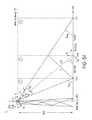
- FIG. 5 cis an illustration of an image segmented into three regions, namely, region 1 , region 2 and region 3 , in accordance with an embodiment of the present invention.
- FIG. 5 dis an illustration of a field-of-view (FOV) of a camera disposed above horizontal ground and configured in a ground surveillance mode.
- FOVfield-of-view
- FIG. 6is an example of a procedure for segmenting a 3D image into foreground frames (region 1 frames), and further segmenting the region 1 frames into 3D image patches, in accordance with an embodiment of the present invention.
- FIG. 7is an example of a procedure for generating a rain mask for each of the 3D image patches of a region (for example, region 1 ), in accordance with an embodiment of the present invention.
- FIG. 8 ais an example of the foreground captured by a surveillance camera.
- FIG. 8 bshows plots of pixel profiles for two different areas (or patches), in which a first area is a high-activity area, whereas a second area is a low-activity area, in accordance with an embodiment of the present invention.
- FIG. 9is an example of a procedure for applying a dynamic rain mask to a highway surveillance camera, in accordance with an embodiment of the present invention.
- FIG. 10is an example of a procedure for applying a dynamic rain mask to an urban surveillance camera, in accordance with an embodiment of the present invention.
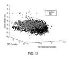
- FIG. 11is an illustration of a 3D scatter plot representing a distribution of rain/no rain statistical features, in accordance with an embodiment of the present invention.
- FIG. 12is an illustration of a video frame being segmented into three regions, in which a detection process divides a region (region 1 ) into patches, with each patch being provided with an output score, s(x), or a posterior probability score, p(R/x), that estimates the presence/absence of rain, snow, or hail, in accordance with an embodiment of the present invention.
- the present inventionprovides a system and method of dynamic weather event detection, such as detecting a raining event, a snowing event, or a hailing event.
- the present inventionuses a sequence of images acquired from a CCT (closed circuit television) network that includes low-resolution surveillance cameras.
- the present inventiononly detects the presence or absence (a binary decision) of dynamic weather events in an image or video sequence. Since the output of the present invention is information (rain or no rain), as opposed to another image, the present invention solves a detection problem, versus solving a de-noising problem or image reconstruction problem that requires removal of rain (or snow) from an image.
- conventional methodsrequire two steps, namely, detection and removal, to provide an output of a restored image.
- the present inventiononly requires a binary decision of rain or no rain, snow or no snow, hail or no hail, etc.
- the present inventionanalyzes the global effect of rain on the video by understanding the properties of rain. For example, rain scintillation is apparent throughout an image sequence; therefore, the present invention segments the video into areas, or regions that increase the probability of detecting rain (or snow, or hail).
- FIG. 1 adepicts an example of a sequence of video frames.
- the sequence of frames (I n )is shown in an X, Y, Z Cartesian coordinate system with time, t, depicted along the Z axis.
- FIG. 1 bshows an example of temporal profiles for selected pixel locations (e.g., sky, rain, tree and road) which cause fluctuations in the intensity values of each pixel as a function of frame number, n.
- pixel locationse.g., sky, rain, tree and road
- rain scintillationproduces small positive intensity changes in pixel intensity.
- the rain scintillation signalis relatively weak, however, compared to the signal strength produced by traffic on a road.
- the present inventionemploys a dynamic rain mask algorithm to automatically segment the video into low and high activity areas.
- static objects/backgroundwhich act as clutter, are also reduced by the dynamic rain mask algorithm.
- the present inventionmeasures the effect of rain on the video, instead of detecting individual rain pixels.
- Photometric effectsrelate to the optical properties of rain.
- Temporal effectsrelate to the dynamic properties of rain, while chromatic effects relate to the manner in which rain interacts with visible light.
- Physical propertiesdescribe the shape, size and velocity of rain. The present invention, however, leverages photometric and temporal characteristics of rain which are independent of scene content. The present invention will now be described below.
- the present inventionmodels a dynamic weather detection system, as shown in FIG. 2 a , generally designated as 10 .
- the system 10includes at least one camera 11 (four cameras, namely, C 1 , C 2 , C 3 and C 4 in a camera network cluster are shown in FIG. 2 b ). Also shown are an image transfer function 12 and two serially connected summation components 13 and 14 .
- ydenotes the acquired image
- ndenotes the background (instrument) noise
- H kdefines the imaging transfer function of the camera.
- H kH atm H opt H det (2)
- H atmdenotes the transfer function of the atmosphere
- H optdenotes the transfer function of the lens system
- H detdenotes the transfer function of the detector used by the camera.
- H kThe explicit definition of H k enables several features for the weather detection system.
- the detection processincorporates properties of the imaging process H k , which varies across the camera network (e.g., geographic locations, cameras and vendors) as illustrated in FIG. 2 b .
- the model shown in FIG. 2 aallows system 10 to directly estimate or predict the detection performance across a network (e.g., between different states) as a function of the camera parameters, namely, H 1 , H 2 , H 3 , and H 4 .
- Equation 3the following binary detection problem may be solved:
- H 0represents a null hypothesis of no dynamic weather events in the image (scene) and H 1 represents a positive case of dynamic weather events in the image.
- the processing pipeline, or method 30includes ingestion of video data or ingestion of image sequences (step 31 ) captured by a camera.
- the next step 32includes image conditioning by a pre-processing module.
- the image conditioningmay include contrast enhancement, de-noising and/or motion stabilization, prior to any other steps. Exploiting the fact that most of the surveillance cameras are stationary, method 30 uses a background subtraction module for each scene to model the static components of the scene. In this manner, method 30 provides step 33 to remove any static components in the scene.
- TEItraffic energy image
- the TEIproduces a visual map of the scene dynamics, where each pixel represents the level of activity in a spatial region integrated over time.
- Distinguishing potential rain pixels from other objects in the sceneis performed by segmentation step 34 , which is handled by a foreground segmentation module that leverages spatial-temporal properties of dynamic weather events. Dynamic clutter is also removed by the foreground segmentation module, which helps reduce false detections.
- Photometric properties of rain (snow)are extracted in step 35 by a feature extraction module which separates rain (snow) pixels from background noise pixels.
- step 36determines the presence or absence of rain. This is determined by the detection module, which returns a binary observation occurrence (BOO) result: (0) No Rain or (1) Rain.
- the BOO resultcorresponds to the output of Equation 4 used by system 10 . More details of these processing components or steps will now be described below.
- DCT-based compression formatse.g., JPEG and MPEG.
- these compression formatsare known to produce several image artifacts including blocking (spatial artifacts) and flickering (temporal artifacts).
- blockingspatial artifacts
- flickeringtemporary artifacts
- the presence of these artifactsproduce false edges and intensity fluctuations in the video that often mimic an appearance of rain (or snow). Therefore, reducing or eliminating these compression artifacts prior to detection helps minimize false alarms and improves the robustness of the detection system.
- FIGS. 4 a , 4 b , 4 c and 4 dshow examples of results from a de-noising algorithm by referring to two images from a surveillance camera in a CCT network.
- FIG. 4 ashows the original compressed image (frame no. 51 ) and
- FIG. 4 cshows the resulting histogram of the original compressed image.
- FIG. 4 bshows the wavelet filtered image (frame no. 51 ) and
- FIG. 4 dshows the resulting histogram of the wavelet filtered image.
- the improvement to the imagemay be evident in the histogram of the wavelet filtered image ( FIG. 4 d ) when compared to the histogram of the original image ( FIG. 4 c ).
- the Background Subtraction Modulesegments the input video into static and dynamic components. Since the weather events are dynamic, they lie within the dynamic component of the video. Stationary areas of the scene are contained in the static component or the background component.
- the background imagecan be updated to adapt to the complex scene changes.
- the Traffic Energy Imagecaptures the spatial-temporal traffic pattern of the scene by identifying the location and strength of traffic motion over the observation time period.
- the TEIproduces a visual map of the scene dynamics, where each pixel represents the level of activity in a spatial region integrated over time.
- ⁇ ndenotes the absolute value of the difference between the input frame and the background image
- M ndenotes the binary motion map
- ⁇ ndenotes the standard deviation of ⁇ n
- T ⁇denotes a user-defined threshold to control the detection.
- the corresponding TEIis determined by integrating the motion maps over the observation period
- the dynamic rain maskis a direct by-product of the TEI and is generated according to the following threshold scheme:
- RainMaskdenotes the rain mask and (i, j) denotes the pixel location. Since the TEI is adaptive to the scene dynamics, the Rain Mask is also adaptive to the traffic and scene motion.
- FIG. 5 ashows an example of the TEI.
- the advantages of the TEIinclude reducing the dynamic clutter from the detection module, a unique spatial-temporal representation of the scene traffic pattern and offers a direct method for generating the dynamic rain mask.
- FIG. 5 billustrates the corresponding rain mask generated from the TEI.
- the white regionsrepresent areas in the scene with no traffic and the dark regions in the scene represent areas with traffic.
- the remaining foreground of the imageincludes moving objects in the scene (e.g., cars, trucks) along with the possible pixels affected by the presence of rain or snow. Since the weather events are dynamic, the present invention segments the rain from other objects in the scene by localizing the rain within the video frames using a spatial-temporal video segmentation approach.
- the spatial componentdetects the local background activity, while the temporal component detects the intensity fluctuations.
- the method of the inventionis scene adaptive and adjusts to local scene content and dynamics. The segmentation component is described below.
- the visibility of rainmay be defined by the intensity change or gradient induced by the raindrops passing in front of the camera. Given the fast motion of the rain, motion of individual raindrops cannot be tracked by human observers. However, the visual appearance of rain manifests as random spatial patterns, or rain scintillation in the video. This visual effect is a result of intensity fluctuations and varies with scene content and distance from the camera.
- FIG. 5 cillustrates a video segmentation strategy employed by system 10 to reduce clutter and improve detection.
- the segmentation step 34divides each image or frame in a video sequence into three regions:
- Region 1focuses on the rain closest to the camera.
- the camerahas the highest chance to capture the rain and the rain is considered to have a fixed intensity level (shown in the figure as a fixed delta of intensity levels).
- Region 2focuses on detecting the rain based on intensity level changes that decrease with increasing distance from the camera.
- the intensity changedecreases with an increase in distance from the camera.
- the detection of rainvaries, or degrades as a function of distance from the camera.
- region 3is furthest from the camera, and the present invention makes no attempt to discern rain from noise in the region. Therefore, Region 3 is not suitable for detection of rain.
- camera 11is disposed at a height of h from horizontal ground and includes a field-of-view (FOV) having a diameter of D.
- FOVfield-of-view
- the near-field in the FOVmakes an angle of B min with horizontal ground and the far-field in the FOV makes an angle of B max with horizontal ground.
- region 1which has the closest scene to the camera, may be partitioned from the other regions in the image, so that only region 1 is used for rain detection; the remaining region or regions may be discarded. As described before, region 1 provides the best opportunity for detecting rain with a low false alarm rate.
- FIG. 6illustrates the procedure for segmenting each selected region (namely, region 1 only; or regions 1 and 2 ) into spatial-temporal image patches for dynamic clutter removal and detection of rain scintillation.
- the objective hereis to localize low activity areas of a scene, which yield optimal locations to detect the presence of rain (or snow). For example, brighter areas of a scene (e.g., sky) yield low contrast between the rain and the background, while darker areas of a scene (e.g., road, street) yield higher contrast between the rain and the background.
- region 1 of each imageis further partitioned into image patches.
- Each image patchincludes N x ⁇ N y pixels, which extends in the temporal direction (Z-axis) by N t frames.
- an image patchconsists of a 3-dimensional (3D) patch of pixels. It will be appreciated that although only 4 patches are shown in region 1 of FIG. 6 , there are many more patches. There may be as many patches as required to encompass all the pixels in region 1 . Accordingly, one patch may be adjacent to another patch in region 1 .
- FIG. 7illustrates a procedure for generating a rain mask.
- each region(for example, region 1 ) is sub-divided into N x ⁇ N y ⁇ N t image patches, where N x ⁇ N y denotes the spatial domain and N t denotes the number of frames in the temporal direction.
- N x ⁇ N ydenotes the spatial domain
- N tdenotes the number of frames in the temporal direction.
- the present inventioncomputes an energy patch level, E p , defined by:
- W(i, j, k)denotes the coefficients of the image patches in a 3D region.
- the patchesare thresholded into low and high activity patches, where high activity patches (e.g., road area) are considered as clutter and removed from the mask.
- the final rain maskcontains the low activity patches, which represent the optimal areas (or patches) to search for the presence of rain. This final rain mask is considered to be a static rain mask.
- the aforementioned static rain maskassumes a fixed camera pose for each detection event.
- the static rain maskis not adequate, due to the random changes in the poses experienced by the cameras. These random changes cause registration errors between the static rain mask and a current scene under observation. Considering the large number of cameras and the unknown time of change, these scenes become difficult to manage with a static rain mask.
- the present inventiontherefore, removes this constraint by using a dynamic rain mask as a preferred approach in the process of detecting rain or snow.
- An algorithm for generating the dynamic rain maskis described below with respect to FIGS. 8 through 10 .
- FIG. 8( a )shows a foreground image (for example, region 1 ) obtained by a surveillance camera, in which several vehicles are captured. Independent of camera pose, most scenes contain unwanted motion (also referred to as dynamic clutter) due to traffic and other moving objects (e.g., trees, pedestrians, etc.). Corresponding pixel profiles at two different locations in the image are shown in FIG. 8( b ) as a function of frame numbers in a video sequence. As shown, the large positive and negative spikes at the first location are induced by moving light and dark vehicles that pass the first location. The small and only positive fluctuations in intensity at the second location, however, is likely due to rain. Two of the properties of rain, thus, are that small and only positive fluctuations are induced by the presence of rain (snow). Accordingly, the present invention filters the foreground image (region 1 ) so that large variations (spikes) in the image data are detected and removed, prior to feature extraction.
- unwanted motionalso referred to as dynamic clutter
- FIG. 8( b )Correspond
- FIGS. 9 and 10illustrate two examples of using this adaptive threshold criteria to generate the dynamic mask.
- the first example in FIG. 9shows a scene from a highway surveillance camera, while the second example in FIG. 10 shows a scene from an urban surveillance camera.
- the methodsegments the region (region 1 ) into dynamic (black) patches and static (white) patches. The black patch areas are eliminated. The white patch areas are used for rain detection. Dynamic patches indicate high activity areas which are most likely caused by vehicles. Static patches, on the other hand, represent low activity areas where the likelihood of detecting scintillation induced by rain increases.
- the feature extractionis performed after image segmentation into white and black patches.
- the feature extractionextracts unique features from the image patches to discern rain from noise pixels. Feature extraction will now be described.
- the present inventionrepresents each image patch by a set of features designed to capture signal variations or fluctuations induced by dynamic weather events.
- the systemprovides a flexible platform for combining multiple features to enhance the detection process.
- the objective of the Rain Feature Extraction moduleis to extract unique features from the image patches to discern rain from noise pixels.
- the present inventionrepresents each image patch by a set of features designed to capture signal variations, or fluctuations induced by the dynamic weather events.
- the systemprovides a flexible platform for combining multiple features to enhance the detection capability.
- Several featuresare considered to detect the temporal fluctuations in the pixel intensities.
- a combination of featuresuse temporal statistics and frequency energy measures including the following features: Normalized Cross-Correlation (NCC), Discrete Cosine Transform Energy Band Ratios (DCT-BER) and Rain Scintillation Index (RSI).
- NCCNormalized Cross-Correlation
- DCT-BERDiscrete Cosine Transform Energy Band Ratios
- RSIRain Scintillation Index
- ⁇ 2denotes the variance of the temporal pixel intensities
- FIG. 11shows a scatter plot for the feature set representing a 3 dimensional (3D) distribution of the statistical features along with the clustering of the two classes (rain/no-rain).
- the present inventionemploys a machine learning approach, which exploits the data rich environment of the camera network.
- the present inventioneliminates the need for any specific model of rain (snow) streaks. This data-driven approach, advantageously, removes any detection error due to inaccurate modeling parameters.
- a detection component of the present inventionuses various machine learning algorithms including Neural Networks (NN) and Support Vector Machines (SVM).
- the detection componentenables a dual-mode detection process, based either on output scores s(x), or on estimated posterior probabilities p(WeatherEvent
- the presence or absence of a dynamic weather eventis determined by using one or a combination of the dual-mode detection process.
- FIG. 12shows a detection strategy with a video frame segmented into three regions using the segmentation component 34 shown in FIG. 3 .
- region 1is closest to the camera.
- the present inventionfurther subdivides region 1 into the 3D image patches, as previously described.
- each 3D image patchrepresents an independent observation of the scene
- the present inventionapplies feature extraction to each 3D image patch using the method shown in FIG. 3 .
- Each feature vector f kis applied to a trained machine learning algorithm to generate either an output score, or an estimated posterior probability.
- One feature vectoris generated for each 3D image patch; thus, M represents the total number of image patches in region 1 , as shown in FIG. 12 . Since each 3D image patch represents an independent observation of the scene, the results from each image patch may be combined to determine the overall probability of detection of the weather event for region 1 (for example).
- the dual-mode detection processuses a Majority Vote test or a Posterior Odds Ratio test (described below).
- the Majority Vote testis used with the score-based output, where the final detection result (i.e., BOO) is determined by selecting the class (e.g., Rain/No-Rain) having the maximum number of responses.
- the goalis to determine the probability of a weather event given the following set of observations: p (WeatherEvent
- ⁇ )p (WeatherEvent
- the present inventionforms the following binary detection test statistic:
- ⁇ ⁇ ( ⁇ )p ⁇ ( Rain
- Equation 8may also be expressed as:
- f k ) ⁇ k1 M ⁇ p ⁇ ( NoRain
- the dual-mode detection processoffers several benefits for detection of dynamic weather events.
- the detection componentis not limited to only rain, but is also applicable to detection of snow, or hail.
- the dual-mode detection processenables using any machine learning algorithm.
- the detection algorithmmay learn directly from real-world data based on what the cameras actually observe. The latter represents a significant advantage over model-based approaches which typically have limited data.
- the present inventionhas many applications.
- the inventionmay be applied to ground based weather surveillance, mobile weather stations, road and driver safety information, and emergency response.
- the inventionmay also be used with weather observation stations, flood warning systems, weather sensor network systems, construction site monitoring and planning systems, city and state weather response and management systems, local weather alerts and forecasting systems, and traffic management systems.
Landscapes
- Engineering & Computer Science (AREA)
- Physics & Mathematics (AREA)
- General Physics & Mathematics (AREA)
- Theoretical Computer Science (AREA)
- Multimedia (AREA)
- Computer Vision & Pattern Recognition (AREA)
- Image Analysis (AREA)
Abstract
Description
y=Hkf+n
y=x+n (1)
Hk=HatmHoptHdet (2)
z=y+r
z=x+n+r (3)
B(i,j)=median{I1(i,j), . . . ,IN(i,j)} (5a)
- μ denotes the mean of the temporal pixel intensities.
These features are averaged across of the patches in the rain mask to produce a final feature vector.
- μ denotes the mean of the temporal pixel intensities.
Γ={f1, . . . ,fM}. (6)
p(WeatherEvent|Γ)=p(WeatherEvent|x1, . . . ,xM). (7)

where
Claims (17)
Priority Applications (2)
| Application Number | Priority Date | Filing Date | Title |
|---|---|---|---|
| US14/339,891US9443142B2 (en) | 2014-07-24 | 2014-07-24 | Vision-based system for dynamic weather detection |
| PCT/US2015/041960WO2016014930A2 (en) | 2014-07-24 | 2015-07-24 | A vision-based system for dynamic weather detection |
Applications Claiming Priority (1)
| Application Number | Priority Date | Filing Date | Title |
|---|---|---|---|
| US14/339,891US9443142B2 (en) | 2014-07-24 | 2014-07-24 | Vision-based system for dynamic weather detection |
Publications (2)
| Publication Number | Publication Date |
|---|---|
| US20160026865A1 US20160026865A1 (en) | 2016-01-28 |
| US9443142B2true US9443142B2 (en) | 2016-09-13 |
Family
ID=53801194
Family Applications (1)
| Application Number | Title | Priority Date | Filing Date |
|---|---|---|---|
| US14/339,891Active2034-12-24US9443142B2 (en) | 2014-07-24 | 2014-07-24 | Vision-based system for dynamic weather detection |
Country Status (2)
| Country | Link |
|---|---|
| US (1) | US9443142B2 (en) |
| WO (1) | WO2016014930A2 (en) |
Cited By (20)
| Publication number | Priority date | Publication date | Assignee | Title |
|---|---|---|---|---|
| US20160055384A1 (en)* | 2014-08-20 | 2016-02-25 | Hyundai Mobis Co., Ltd. | Vehicle control method for safety driving and device thereof |
| US20160334811A1 (en)* | 2015-05-12 | 2016-11-17 | Echostar Technologies L.L.C. | Home automation weather detection |
| US9838736B2 (en) | 2013-12-11 | 2017-12-05 | Echostar Technologies International Corporation | Home automation bubble architecture |
| US9882736B2 (en) | 2016-06-09 | 2018-01-30 | Echostar Technologies International Corporation | Remote sound generation for a home automation system |
| US9946857B2 (en) | 2015-05-12 | 2018-04-17 | Echostar Technologies International Corporation | Restricted access for home automation system |
| US9960980B2 (en) | 2015-08-21 | 2018-05-01 | Echostar Technologies International Corporation | Location monitor and device cloning |
| US9967614B2 (en) | 2014-12-29 | 2018-05-08 | Echostar Technologies International Corporation | Alert suspension for home automation system |
| US9977587B2 (en) | 2014-10-30 | 2018-05-22 | Echostar Technologies International Corporation | Fitness overlay and incorporation for home automation system |
| US9983011B2 (en) | 2014-10-30 | 2018-05-29 | Echostar Technologies International Corporation | Mapping and facilitating evacuation routes in emergency situations |
| US9989507B2 (en) | 2014-09-25 | 2018-06-05 | Echostar Technologies International Corporation | Detection and prevention of toxic gas |
| US9996066B2 (en) | 2015-11-25 | 2018-06-12 | Echostar Technologies International Corporation | System and method for HVAC health monitoring using a television receiver |
| US10049515B2 (en) | 2016-08-24 | 2018-08-14 | Echostar Technologies International Corporation | Trusted user identification and management for home automation systems |
| US10060644B2 (en) | 2015-12-31 | 2018-08-28 | Echostar Technologies International Corporation | Methods and systems for control of home automation activity based on user preferences |
| US10073428B2 (en) | 2015-12-31 | 2018-09-11 | Echostar Technologies International Corporation | Methods and systems for control of home automation activity based on user characteristics |
| US10091017B2 (en) | 2015-12-30 | 2018-10-02 | Echostar Technologies International Corporation | Personalized home automation control based on individualized profiling |
| US10101717B2 (en) | 2015-12-15 | 2018-10-16 | Echostar Technologies International Corporation | Home automation data storage system and methods |
| US10200752B2 (en) | 2013-12-16 | 2019-02-05 | DISH Technologies L.L.C. | Methods and systems for location specific operations |
| US10294600B2 (en) | 2016-08-05 | 2019-05-21 | Echostar Technologies International Corporation | Remote detection of washer/dryer operation/fault condition |
| US11134201B2 (en) | 2019-08-20 | 2021-09-28 | International Business Machines Corporation | Vision assisted driving system using a vertically extendable camera |
| TWI767300B (en)* | 2020-08-18 | 2022-06-11 | 廣達電腦股份有限公司 | Computing device and method of removing raindrops in video images |
Families Citing this family (23)
| Publication number | Priority date | Publication date | Assignee | Title |
|---|---|---|---|---|
| US9465987B1 (en)* | 2015-03-17 | 2016-10-11 | Exelis, Inc. | Monitoring and detecting weather conditions based on images acquired from image sensor aboard mobile platforms |
| US10049284B2 (en)* | 2016-04-11 | 2018-08-14 | Ford Global Technologies | Vision-based rain detection using deep learning |
| CN106971378A (en)* | 2016-08-23 | 2017-07-21 | 上海海洋大学 | A kind of removing rain based on single image method based on depth denoising self-encoding encoder |
| US10198841B2 (en) | 2016-11-30 | 2019-02-05 | Gopro, Inc. | Map view |
| CN107909556B (en)* | 2017-11-27 | 2021-11-23 | 天津大学 | Video image rain removing method based on convolutional neural network |
| CN108052206B (en)* | 2018-01-05 | 2021-08-13 | 重庆爱奇艺智能科技有限公司 | Video playing method and device and electronic equipment |
| CN109360156B (en)* | 2018-08-17 | 2020-08-28 | 上海交通大学 | A single image rain removal method based on image segmentation based on generative adversarial network |
| JP7281041B2 (en)* | 2018-11-29 | 2023-05-25 | 京セラドキュメントソリューションズ株式会社 | Type discrimination system |
| CN110009578B (en)* | 2019-03-13 | 2022-11-15 | 五邑大学 | Image rain removing method and system, device and storage medium thereof |
| CN110321774B (en)* | 2019-04-04 | 2022-05-17 | 平安科技(深圳)有限公司 | Crop disaster situation evaluation method, device, equipment and computer readable storage medium |
| CN110717863B (en)* | 2019-08-16 | 2023-07-04 | 天津大学 | A Single Image Snow Removal Method Based on Generative Adversarial Network |
| CN110751612A (en)* | 2019-11-05 | 2020-02-04 | 哈尔滨理工大学 | Single image rain removing method of multi-channel multi-scale convolution neural network |
| TWI739203B (en)* | 2019-11-08 | 2021-09-11 | 大猩猩科技股份有限公司 | A method and system of evaluating the valid analysis region of images |
| CN111160125B (en)* | 2019-12-11 | 2023-06-30 | 北京交通大学 | Railway foreign matter intrusion detection method based on railway monitoring |
| CN111210394A (en)* | 2020-01-03 | 2020-05-29 | 北京智云视图科技有限公司 | Image enhancement technology based on deep decomposition synthesis network |
| CN111591285B (en)* | 2020-03-19 | 2020-12-25 | 平湖市伊凡家箱包有限公司 | Snow distribution state monitoring system applying cloud computing |
| WO2021236237A2 (en)* | 2020-04-01 | 2021-11-25 | Sarcos Corp. | System and methods for early detection of non-biological mobile aerial target |
| CN114417742B (en)* | 2022-04-01 | 2022-06-10 | 中国工程物理研究院流体物理研究所 | A laser atmospheric scintillation index prediction method and system |
| CN116958190A (en)* | 2022-04-14 | 2023-10-27 | 华为技术有限公司 | Dynamic scene processing method, neural network model training method and device |
| CN114863332B (en)* | 2022-04-29 | 2024-08-27 | 华中科技大学 | Raindrop detection method based on event camera |
| CN116188586B (en)* | 2023-04-25 | 2023-06-27 | 新乡学院 | Positioning system and method based on light distribution |
| CN116935289B (en)* | 2023-09-13 | 2023-12-19 | 长江信达软件技术(武汉)有限责任公司 | Open channel embankment detection method based on video monitoring |
| CN118135465B (en)* | 2024-05-08 | 2024-07-16 | 南京大学 | Night raindrop falling speed measuring method and system based on monitoring near infrared video |
Citations (8)
| Publication number | Priority date | Publication date | Assignee | Title |
|---|---|---|---|---|
| US6625310B2 (en)* | 2001-03-23 | 2003-09-23 | Diamondback Vision, Inc. | Video segmentation using statistical pixel modeling |
| EP1521694A2 (en) | 2002-07-16 | 2005-04-13 | TRW Limited | Rain detection apparatus and method |
| US7098618B2 (en) | 2004-06-24 | 2006-08-29 | Denso Corporation | Rain detection system and method of controlling the same |
| US20070280504A1 (en)* | 2006-05-30 | 2007-12-06 | Wael Badawy | Detection of environmental conditions in a sequence of images |
| US20100040285A1 (en)* | 2008-08-14 | 2010-02-18 | Xerox Corporation | System and method for object class localization and semantic class based image segmentation |
| US20120008866A1 (en)* | 2010-06-28 | 2012-01-12 | Jad Halimeh | Method and device for detecting an interfering object in a camera image |
| US8436902B2 (en)* | 2007-08-30 | 2013-05-07 | Valeo Schalter And Sensoren Gmbh | Method and system for weather condition detection with image-based road characterization |
| US20130242188A1 (en) | 2010-11-15 | 2013-09-19 | Indian Institute Of Technology, Kharagpur | Method and Apparatus for Detection and Removal of Rain from Videos using Temporal and Spatiotemporal Properties |
- 2014
- 2014-07-24USUS14/339,891patent/US9443142B2/enactiveActive
- 2015
- 2015-07-24WOPCT/US2015/041960patent/WO2016014930A2/enactiveApplication Filing
Patent Citations (8)
| Publication number | Priority date | Publication date | Assignee | Title |
|---|---|---|---|---|
| US6625310B2 (en)* | 2001-03-23 | 2003-09-23 | Diamondback Vision, Inc. | Video segmentation using statistical pixel modeling |
| EP1521694A2 (en) | 2002-07-16 | 2005-04-13 | TRW Limited | Rain detection apparatus and method |
| US7098618B2 (en) | 2004-06-24 | 2006-08-29 | Denso Corporation | Rain detection system and method of controlling the same |
| US20070280504A1 (en)* | 2006-05-30 | 2007-12-06 | Wael Badawy | Detection of environmental conditions in a sequence of images |
| US8436902B2 (en)* | 2007-08-30 | 2013-05-07 | Valeo Schalter And Sensoren Gmbh | Method and system for weather condition detection with image-based road characterization |
| US20100040285A1 (en)* | 2008-08-14 | 2010-02-18 | Xerox Corporation | System and method for object class localization and semantic class based image segmentation |
| US20120008866A1 (en)* | 2010-06-28 | 2012-01-12 | Jad Halimeh | Method and device for detecting an interfering object in a camera image |
| US20130242188A1 (en) | 2010-11-15 | 2013-09-19 | Indian Institute Of Technology, Kharagpur | Method and Apparatus for Detection and Removal of Rain from Videos using Temporal and Spatiotemporal Properties |
Non-Patent Citations (42)
| Title |
|---|
| Barnum, P., Kanade, T. and Narasimhan, S.G., "Spatio-Temporal Frequency Analysis for Removing Rain and Snow from Videos", Proceedings of the First International Workshop on Photometric Analysis for Computer Vision (PACV), 2007. |
| Barnum, P.C., Narasimhan, S. and Kanade, T., "Analysis of Rain and Snow in Frequency Space", International Journal on Computer Vision (Online), Jan. 2009. |
| Beard, K. V. and Chuang, C., "A New Model for the Equilibrium Shape of Raindrops", Journal of the Atmospheric Sciences, vol. 44, No. 11, pp. 1509-1524, Jun. 1987. |
| Bossu, J., Hautiere, N. and Tarel, J.P., "Rain or Snow Detection in Image Sequences Through Use of a Histogram of Orientation of Streaks", International Journal on Computer Vision, vol. 93, pp. 348-367, 2011. |
| Chen, J. and Chau, L.P., "Rain Removal from Dynamic Scene Based on Motion Segmentation", IEEE International Symposium on Circuits and Systems (ISCAS), pp. 2139-2142, 2013. |
| Elgammal, A., Harwood, D., Davis, L.,"Non-parametric Model for Background Subtraction", Proceedings of the European Conference on Computer Vision, Dublin, Ireland, vol. II, pp. 751-767, 2000. |
| Garg, K. and Nayar, S. K., "Vision and Rain", International Journal of Computer Vision, 2007. |
| Garg, K. and Nayar, S.K., "Detection and Removal of Rain from Videos", Proceedings of the IEEE Conference on Computer Vision and Pattern Recognition (CVPR), 2004. |
| Garg, K. and Nayar, S.K., "When Does a Camera See Rain?", Proceedings of the IEEE International Conference on Computer Vision (ICCV), 2005. |
| Gunn, R. and Kinzer, G.D., "The Terminal Velocity of Fall for Water Droplets in Stagnant Air", Journal of Meteorology, vol. 6, pp. 243-248, Aug. 1949. |
| Hase, H., Miyake, K. and Yoneda, M., "Real-time Snowfall Noise Elimination", IEEE International Conference on Image Processing (ICIP), pp. 406-409, 1999. |
| Hautière, N., Bigorgne, E., Bossu, J. and Aubert, D., "Meteorological Conditions Processing for Vision-based Traffic Monitoring", Dans: The Eighth International Workshop on Visual Surveillance (VS2008), 2008. |
| Hautiere, N., Bossu, J., Biogorgne, E., Hilblot, N., Boubezoul, A., Lusetti, B. and Aubert,D., "Sensing the Visibility Range at Low Cost in the Safespot Roadside Unit". 2009.* |
| http://climate.com/products/ciimate-basic, The Climate Technology Platform, Jan. 20, 2014. |
| http://www.prnewswire.com/news-releases/the-climate-corporation-introduces-climate-basic, press release Nov. 5, 2013. |
| International Search Report and Written Opinion of the International Searching Authority, International Application No. PCT/US2015/041960, dated Jan. 12, 2016. |
| Jacobs, N., et al., "The Global Network of Outdoor Webcams: Properties and Applications", ACM GIS'09, Nov. 2009. |
| Koenderink, J.J. and Richards, W.A., "Why is snow so bright?", Journal Optical Society of America, vol. 9, No. 5, pp. 643-648, May 1992. |
| Krishnan, S. and Venkataraman, D., "Restoration of Video by Removing Rain", International Journal of Computer Science, Engineering and Applications (IJCSEA), vol. 2, No. 2, pp. 19-28, Apr. 2012. |
| Liu, P., Xu, J., Liu, J. and Tang, X., "Pixel based Temporal Analysis Using Chromatic Property for Removing Rain from Videos", Computer and Information Sciences, vol. 2, No. 1, pp. 53-60, Feb. 2009. |
| Narasimhan, S. G., et al., "Vision and the Atmosphere", International Journal of Computer Vision, vol. 48, No. 3, pp. 233-254, 2002. |
| Park, W.J. and Lee, K.H., "Rain Removal Using Kalman Filter in Video", IEEE International Conference on Smart Manufacturing Application, pp. 494-497, Apr. 2008. |
| Radke, Richard J., et al., "Image Change Detection Algorithms: A Systematic Survey", IEEE Transactions on Image Processing, vol. 14, No. 3, pp. 294-307, Mar. 2005. |
| Renhorn, I.G.E, Svensson, T., Carlsson, G., Cronström, S. and Boreman, G.D., "Infrared image scintillation: comparison of modeling and measurement", Optical Engineering, vol. 45, No. 1, Jan. 2006. |
| Santhaseelan, V. and Asari, V.K., "A Phase Space Approach for Detection and Removal of Rain in Video", Proceedings of SPIE: Intelligent Robots and Computer Vision XXIX: Algorithm and Techniques, vol. 8301, 2012. |
| Santhaseelan, V. and Asari, V.K., "Phase Congruency Based Technique for the Removal of Rain from Video", ICIAR, pp. 30-39, 2011. |
| Sathita, K., Ochiai, H. and Esaki, H., "RainWatch Project: Location-Awared Realtime Detection and Notification of Rain on Internet-Based Sensor Network", IEEE Ninth Annual International Symposium on Applications and the Internet, pp. 259-262, 2009. |
| Shen, M. and Xue, P., "A Fast Algorithm for Rain Detection and Removal from Videos", IEEE International Conference on Multimedia Expo (ICME), pp. 1-6, 2011. |
| Tripathi, A.K. and Mukhopadhyay, S., "A probabilistic approach for detection and removal of rain from videos", IETE Journal of Research, vol. 57, No. 1, pp. 82-91, 2011. |
| Tripathi, A.K. and Mukhopadhyay, S., "Meteorological approach for detection and removal of rain from videos", IET Computer Vision, vol. 7, Issue 1, pp. 36-47, 2013. |
| Tripathi, A.K. and Mukhopadhyay, S., "Removal of rain from videos: a review", Signal, Image and Video Processing, Sep. 2012. |
| Tripathi, A.K. and Mukhopadyay, S., "Video post processing: low-latency spatiotemporal approach for detection and removal of rain", IET Image Processing, vol. 6, Issue 2, pp. 181-196, 2012. |
| Wahab, M.H.A., Su,C.H., Zakaria, N. and Salam, R.A., "Review on Raindrop Detection and Removal in Weather Degraded Images", IEEE International Conference on Computer Science and Information Technology (CSIT), pp. 82-88, 2013. |
| Wang, D.J., Chen, T.H., Liau, H.S. and Chen, T.Y., "A DCT-Based Video Object Segmentation Algorithm for Rainy Situation Using Change Detection", IEEE International Conference on Innovative Computing, Information and Control (ICICIC), 2006. |
| Wang, T. and Clifford, S.F., "Use of rainfall-induced optical scintillation to measure path-averaged rain parameters", Journal of the Optical Society of America, vol. 65, No. 8, pp. 927-937, Aug. 1975. |
| Wu, Q., Zhang, W. and Vijaya Kumar, B.V.K, "Raindrop Detection and Removal Using Salient Visual Features", IEEE International Conference on Image Processing (ICIP), pp. 941-944, 2012. |
| Xu, J., Zhao, W., Liu, P. and Tang, X., "Removing rain and snow in a single image using guided filter", IEEE International Conference on Computer Science and Automation Engineering (CSAE), pp. 304-307, 2012. |
| Xue, X., Jin, X., Zhang, C. and Goto, S., "Motion Robust Rain Detection and Removal from Videos", IEEE MMSP, pp. 170-174, 2012. |
| Zhang, X., Li, H., Qi, Y., Leow, W.K. and Ng, T.K., "Rain Removal in Video by Combining Temporal and Chromatic Properties", IEEE International Conference on Multimedia Expo (ICME), pp. 461-464, 2006. |
| Zhao, X., Liu, P., Liu, J. and Tang, X., "Removal of dynamic weather conditions based on variable time window", IET Computer Vision, vol. 7, Issue 4, pp. 219-226, 2013. |
| Zhao, X., Liu, P., Liu, J. and Tang, X., "The Application of Histogram on Rain Detection in Video", Proceedings of the 11th Joint Conference on Information Sciences, pp. 1-6, 2008. |
| Zhou, M., Zhu, Z., Deng, R. and Fang, S., "Rain Detection and Removal of Sequential Images", IEEE Chinese Control and Decision Conference (CCDC), pp. 615-618, 2011. |
Cited By (26)
| Publication number | Priority date | Publication date | Assignee | Title |
|---|---|---|---|---|
| US9838736B2 (en) | 2013-12-11 | 2017-12-05 | Echostar Technologies International Corporation | Home automation bubble architecture |
| US9900177B2 (en) | 2013-12-11 | 2018-02-20 | Echostar Technologies International Corporation | Maintaining up-to-date home automation models |
| US9912492B2 (en) | 2013-12-11 | 2018-03-06 | Echostar Technologies International Corporation | Detection and mitigation of water leaks with home automation |
| US10027503B2 (en) | 2013-12-11 | 2018-07-17 | Echostar Technologies International Corporation | Integrated door locking and state detection systems and methods |
| US11109098B2 (en) | 2013-12-16 | 2021-08-31 | DISH Technologies L.L.C. | Methods and systems for location specific operations |
| US10200752B2 (en) | 2013-12-16 | 2019-02-05 | DISH Technologies L.L.C. | Methods and systems for location specific operations |
| US20160055384A1 (en)* | 2014-08-20 | 2016-02-25 | Hyundai Mobis Co., Ltd. | Vehicle control method for safety driving and device thereof |
| US9798937B2 (en)* | 2014-08-20 | 2017-10-24 | Hyundai Mobis Co., Ltd | Vehicle control method for safety driving and device thereof |
| US9989507B2 (en) | 2014-09-25 | 2018-06-05 | Echostar Technologies International Corporation | Detection and prevention of toxic gas |
| US9983011B2 (en) | 2014-10-30 | 2018-05-29 | Echostar Technologies International Corporation | Mapping and facilitating evacuation routes in emergency situations |
| US9977587B2 (en) | 2014-10-30 | 2018-05-22 | Echostar Technologies International Corporation | Fitness overlay and incorporation for home automation system |
| US9967614B2 (en) | 2014-12-29 | 2018-05-08 | Echostar Technologies International Corporation | Alert suspension for home automation system |
| US9946857B2 (en) | 2015-05-12 | 2018-04-17 | Echostar Technologies International Corporation | Restricted access for home automation system |
| US9948477B2 (en)* | 2015-05-12 | 2018-04-17 | Echostar Technologies International Corporation | Home automation weather detection |
| US20160334811A1 (en)* | 2015-05-12 | 2016-11-17 | Echostar Technologies L.L.C. | Home automation weather detection |
| US9960980B2 (en) | 2015-08-21 | 2018-05-01 | Echostar Technologies International Corporation | Location monitor and device cloning |
| US9996066B2 (en) | 2015-11-25 | 2018-06-12 | Echostar Technologies International Corporation | System and method for HVAC health monitoring using a television receiver |
| US10101717B2 (en) | 2015-12-15 | 2018-10-16 | Echostar Technologies International Corporation | Home automation data storage system and methods |
| US10091017B2 (en) | 2015-12-30 | 2018-10-02 | Echostar Technologies International Corporation | Personalized home automation control based on individualized profiling |
| US10073428B2 (en) | 2015-12-31 | 2018-09-11 | Echostar Technologies International Corporation | Methods and systems for control of home automation activity based on user characteristics |
| US10060644B2 (en) | 2015-12-31 | 2018-08-28 | Echostar Technologies International Corporation | Methods and systems for control of home automation activity based on user preferences |
| US9882736B2 (en) | 2016-06-09 | 2018-01-30 | Echostar Technologies International Corporation | Remote sound generation for a home automation system |
| US10294600B2 (en) | 2016-08-05 | 2019-05-21 | Echostar Technologies International Corporation | Remote detection of washer/dryer operation/fault condition |
| US10049515B2 (en) | 2016-08-24 | 2018-08-14 | Echostar Technologies International Corporation | Trusted user identification and management for home automation systems |
| US11134201B2 (en) | 2019-08-20 | 2021-09-28 | International Business Machines Corporation | Vision assisted driving system using a vertically extendable camera |
| TWI767300B (en)* | 2020-08-18 | 2022-06-11 | 廣達電腦股份有限公司 | Computing device and method of removing raindrops in video images |
Also Published As
| Publication number | Publication date |
|---|---|
| US20160026865A1 (en) | 2016-01-28 |
| WO2016014930A2 (en) | 2016-01-28 |
| WO2016014930A3 (en) | 2016-03-24 |
Similar Documents
| Publication | Publication Date | Title |
|---|---|---|
| US9443142B2 (en) | Vision-based system for dynamic weather detection | |
| Amato et al. | Deep learning for decentralized parking lot occupancy detection | |
| US10607089B2 (en) | Re-identifying an object in a test image | |
| US9230175B2 (en) | System and method for motion detection in a surveillance video | |
| Zheng et al. | A novel vehicle detection method with high resolution highway aerial image | |
| EP1836683B1 (en) | Method for tracking moving object in video acquired of scene with camera | |
| US20180151063A1 (en) | Real-time detection system for parked vehicles | |
| CN114299002A (en) | An intelligent detection system and method for abnormal behavior of pavement throwing | |
| Hu et al. | A novel approach for crowd video monitoring of subway platforms | |
| FAN et al. | Robust lane detection and tracking based on machine vision | |
| Liu et al. | Vehicle detection from aerial color imagery and airborne LiDAR data | |
| Katiyar et al. | Single image haze removal algorithm using color attenuation prior and multi-scale fusion | |
| CN119206530A (en) | A method, device, equipment and medium for dynamic target recognition of remote sensing images | |
| Lagorio et al. | Automatic detection of adverse weather conditions in traffic scenes | |
| Chen et al. | Automatic head detection for passenger flow analysis in bus surveillance videos | |
| Buch | eLondon | |
| Al-Refai et al. | A framework for background modeling using vehicle-to-infrastructure communication for improved candidate generation in pedestrian detection | |
| Hinz et al. | Detection and tracking of vehicles in low framerate aerial image sequences | |
| Banu et al. | Video based vehicle detection using morphological operation and hog feature extraction | |
| Zhou | EKF based object detect and tracking for UAV by using visual-attention-model | |
| Liu et al. | A joint optical flow and principal component analysis approach for motion detection | |
| Mejía-Iñigo et al. | Color-based texture image segmentation for vehicle detection | |
| Mishra | Automatic moving vehicle's information extraction from one-pass WorldView-2 satellite imagery | |
| Koch et al. | Road segmentation using multipass single-pol synthetic aperture radar imagery | |
| Huber et al. | Bio-inspired'surprise'for real-time change detection in visual imagery |
Legal Events
| Date | Code | Title | Description |
|---|---|---|---|
| AS | Assignment | Owner name:EXELIS, INC., VIRGINIA Free format text:ASSIGNMENT OF ASSIGNORS INTEREST;ASSIGNOR:TELEDYNE SCIENTIFIC & IMAGING, LLC;REEL/FRAME:033385/0263 Effective date:20140723 Owner name:TELEDYNE SCIENTIFIC & IMAGING, LLC, CALIFORNIA Free format text:ASSIGNMENT OF ASSIGNORS INTEREST;ASSIGNOR:REYNOLDS, WILLIAM D., JR.;REEL/FRAME:033385/0222 Effective date:20140722 | |
| STCF | Information on status: patent grant | Free format text:PATENTED CASE | |
| AS | Assignment | Owner name:HARRIS CORPORATION, FLORIDA Free format text:MERGER;ASSIGNOR:EXELIS INC.;REEL/FRAME:044284/0675 Effective date:20151223 | |
| MAFP | Maintenance fee payment | Free format text:PAYMENT OF MAINTENANCE FEE, 4TH YEAR, LARGE ENTITY (ORIGINAL EVENT CODE: M1551); ENTITY STATUS OF PATENT OWNER: LARGE ENTITY Year of fee payment:4 | |
| MAFP | Maintenance fee payment | Free format text:PAYMENT OF MAINTENANCE FEE, 8TH YEAR, LARGE ENTITY (ORIGINAL EVENT CODE: M1552); ENTITY STATUS OF PATENT OWNER: LARGE ENTITY Year of fee payment:8 |