US9442688B2 - Synchronized display system - Google Patents
Synchronized display systemDownload PDFInfo
- Publication number
- US9442688B2 US9442688B2US14/082,241US201314082241AUS9442688B2US 9442688 B2US9442688 B2US 9442688B2US 201314082241 AUS201314082241 AUS 201314082241AUS 9442688 B2US9442688 B2US 9442688B2
- Authority
- US
- United States
- Prior art keywords
- display
- flat panel
- seat
- display screen
- positions
- Prior art date
- Legal status (The legal status is an assumption and is not a legal conclusion. Google has not performed a legal analysis and makes no representation as to the accuracy of the status listed.)
- Active, expires
Links
Images


Classifications
- B—PERFORMING OPERATIONS; TRANSPORTING
- B60—VEHICLES IN GENERAL
- B60R—VEHICLES, VEHICLE FITTINGS, OR VEHICLE PARTS, NOT OTHERWISE PROVIDED FOR
- B60R11/00—Arrangements for holding or mounting articles, not otherwise provided for
- B60R11/02—Arrangements for holding or mounting articles, not otherwise provided for for radio sets, television sets, telephones, or the like; Arrangement of controls thereof
- B60R11/0229—Arrangements for holding or mounting articles, not otherwise provided for for radio sets, television sets, telephones, or the like; Arrangement of controls thereof for displays, e.g. cathodic tubes
- G—PHYSICS
- G06—COMPUTING OR CALCULATING; COUNTING
- G06F—ELECTRIC DIGITAL DATA PROCESSING
- G06F3/00—Input arrangements for transferring data to be processed into a form capable of being handled by the computer; Output arrangements for transferring data from processing unit to output unit, e.g. interface arrangements
- G06F3/14—Digital output to display device ; Cooperation and interconnection of the display device with other functional units
- G06F3/1454—Digital output to display device ; Cooperation and interconnection of the display device with other functional units involving copying of the display data of a local workstation or window to a remote workstation or window so that an actual copy of the data is displayed simultaneously on two or more displays, e.g. teledisplay
- B—PERFORMING OPERATIONS; TRANSPORTING
- B60—VEHICLES IN GENERAL
- B60N—SEATS SPECIALLY ADAPTED FOR VEHICLES; VEHICLE PASSENGER ACCOMMODATION NOT OTHERWISE PROVIDED FOR
- B60N2/00—Seats specially adapted for vehicles; Arrangement or mounting of seats in vehicles
- B60N2/02—Seats specially adapted for vehicles; Arrangement or mounting of seats in vehicles the seat or part thereof being movable, e.g. adjustable
- B60N2/22—Seats specially adapted for vehicles; Arrangement or mounting of seats in vehicles the seat or part thereof being movable, e.g. adjustable the back-rest being adjustable
- B—PERFORMING OPERATIONS; TRANSPORTING
- B60—VEHICLES IN GENERAL
- B60R—VEHICLES, VEHICLE FITTINGS, OR VEHICLE PARTS, NOT OTHERWISE PROVIDED FOR
- B60R11/00—Arrangements for holding or mounting articles, not otherwise provided for
- B60R11/02—Arrangements for holding or mounting articles, not otherwise provided for for radio sets, television sets, telephones, or the like; Arrangement of controls thereof
- B60R11/0229—Arrangements for holding or mounting articles, not otherwise provided for for radio sets, television sets, telephones, or the like; Arrangement of controls thereof for displays, e.g. cathodic tubes
- B60R11/0235—Arrangements for holding or mounting articles, not otherwise provided for for radio sets, television sets, telephones, or the like; Arrangement of controls thereof for displays, e.g. cathodic tubes of flat type, e.g. LCD
- B—PERFORMING OPERATIONS; TRANSPORTING
- B60—VEHICLES IN GENERAL
- B60R—VEHICLES, VEHICLE FITTINGS, OR VEHICLE PARTS, NOT OTHERWISE PROVIDED FOR
- B60R11/00—Arrangements for holding or mounting articles, not otherwise provided for
- B60R2011/0001—Arrangements for holding or mounting articles, not otherwise provided for characterised by position
- B60R2011/0003—Arrangements for holding or mounting articles, not otherwise provided for characterised by position inside the vehicle
- B60R2011/0028—Ceiling, e.g. roof rails
- B—PERFORMING OPERATIONS; TRANSPORTING
- B60—VEHICLES IN GENERAL
- B60R—VEHICLES, VEHICLE FITTINGS, OR VEHICLE PARTS, NOT OTHERWISE PROVIDED FOR
- B60R11/00—Arrangements for holding or mounting articles, not otherwise provided for
- B60R2011/0042—Arrangements for holding or mounting articles, not otherwise provided for characterised by mounting means
- B60R2011/008—Adjustable or movable supports
- B60R2011/0082—Adjustable or movable supports collapsible, e.g. for storing after use
- B—PERFORMING OPERATIONS; TRANSPORTING
- B60—VEHICLES IN GENERAL
- B60R—VEHICLES, VEHICLE FITTINGS, OR VEHICLE PARTS, NOT OTHERWISE PROVIDED FOR
- B60R11/00—Arrangements for holding or mounting articles, not otherwise provided for
- B60R2011/0042—Arrangements for holding or mounting articles, not otherwise provided for characterised by mounting means
- B60R2011/008—Adjustable or movable supports
- B60R2011/0092—Adjustable or movable supports with motorization
Definitions
- the present inventionrelates generally to display systems and, more particularly, to a synchronized display system.
- laptop computerno longer requires that the user compromise on processor speed, display size, display resolution or memory. Additionally, given the battery life available in many such computers, the user is no longer required to limit their use to small working sessions. As a result, laptops have become a viable alternative for many professionals, offering the end user both the performance that they have come to expect from a desktop computer as well as the portability and convenience associated with a laptop. Unfortunately while the performance of laptop computers have improved dramatically over the last decade, their usefulness is still limited due to the setting in which they are often used.
- the positioning systemincludes (i) a display mounted within and to a vehicle, where the display may be adjusted within a range of display positions, (ii) a display positioning system coupled to the display, (iii) a vehicle seat adjustable within a range of positions, (iv) a vehicle seat sensor that outputs seat position data corresponding to the seat's current position, and (v) a control system coupled to the display positioning system and to the vehicle's seat sensors, where the control system monitors the seat sensors to determine the current seat position and adjusts the display's position in response to the current seat position.
- the control systemmay use a look-up table stored in memory to select the appropriate display position that corresponds to the current seat position, where the look-up table includes a plurality of compatible display positions that correspond to the available range of seat positions, and where each of the compatible display positions may be set to maintain (i) display viewing distance, (ii) display viewing height, and/or (iii) display viewing angle within a preset range.
- the display positioning systemmay utilize an electro-mechanical positioning system or a hydraulic positioning system.
- the linkage assembly that mounts the display to the vehicle and which is used by the positioning system and the controller to adjust the display's position in response to the seat being repositionedmay (i) utilize a link that slides within a track mounted to the vehicle, (ii) utilize a telescoping link, and/or (iii) utilize a multi-link assembly that includes a first link pivotably coupled to the display and to a second link, and a second link pivotably coupled to the first link and the vehicle.
- the systemmay also include a user interface, where the control system is configured to accept a set of display settings (e.g., display viewing distance, display viewing height, display viewing angle, etc.) via the user interface and then adjust the range of compatible display positions to maintain the display settings when the display is adjusted in response to a change in the seat position.
- a set of display settingse.g., display viewing distance, display viewing height, display viewing angle, etc.
- a method of positioning a display within a vehicleincluding the steps of (i) determining a current seat position from a range of available seat positions for a vehicle seat, (ii) providing the current seat position to a control system, (iii) automatically selecting a display position from a plurality of compatible display positions based on the current seat position, and (iv) moving the display to the display position selected by the control system, for example by manipulating a linkage assembly coupling the display to the vehicle, where the step of moving the display is performed automatically by a display positioning system controlled by the control system.
- the methodmay include the step of moving the display from a storage position to a display position when (i) the display is activated, and/or (ii) a video source coupled to the display is activated.
- the methodmay include the step of moving the display from a display position to a storage position when (i) the display is deactivated, (ii) a video source coupled to the display is deactivated, (iii) the vehicle is turned off, and/or (iv) the vehicle is placed into park.
- the methodmay include the step of presetting the plurality of compatible display positions to maintain (i) display viewing distance, (ii) display viewing height, and/or (iii) display viewing angle within a preset range when the display is moved in response to a repositioning of the vehicle's seat.
- the methodmay include the steps of accepting a set of display settings (e.g., display viewing distance, height, angle, etc.) for a particular seat position and then adjusting the plurality of compatible display positions to maintain the set of display settings throughout the range of available seat positions.
- a set of display settingse.g., display viewing distance, height, angle, etc.
- FIG. 1provides a block diagram of the primary subsystems associated with the invention
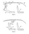
- FIG. 2provides a side view of an embodiment of the invention with the display stored
- FIG. 3provides a side view of the synchronized display shown in FIG. 2 with the display positioned for use with a generally upright seat;
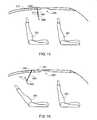
- FIG. 4provides a side view of the synchronized display shown in FIGS. 2 and 3 with the display re-positioned for use with a partially reclining seat;
- FIG. 5provides a side view of the synchronized display shown in FIGS. 2-4 with the display re-positioned for use with a fully reclining seat;
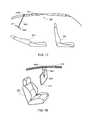
- FIG. 6provides a side view of the synchronized display shown in FIGS. 2-5 that illustrates re-positioning the display as the seat is moved backwards;
- FIG. 7provides a side view of the synchronized display shown in FIGS. 2-6 that illustrates re-positioning the display as the seat is lowered;
- FIG. 8illustrates the display characteristics of viewing distance, height and angle
- FIG. 9illustrates a modified block diagram based on FIG. 1 in which a user interface is added that allows the user to input viewing preferences;
- FIG. 10provides a side view of an alternate embodiment of the invention with the display stored
- FIG. 11provides a side view of the synchronized display shown in FIG. 10 with the display positioned for use with a generally upright seat;
- FIG. 12provides a side view of the synchronized display shown in FIGS. 10 and 11 with the display re-positioned for use with a partially reclining seat;
- FIG. 13provides a side view of the synchronized display shown in FIGS. 10-12 with the display re-positioned for use with a fully reclining seat;
- FIG. 14provides a side view of an alternate embodiment of the invention with the display stored
- FIG. 15provides a side view of the synchronized display shown in FIG. 14 with the display positioned for use with a generally upright seat;
- FIG. 16provides a side view of the synchronized display shown in FIGS. 14 and 15 with the display re-positioned for use with a partially reclining seat;
- FIG. 17provides a side view of the synchronized display shown in FIGS. 14-16 with the display re-positioned for use with a fully reclining seat;
- FIG. 18provides a perspective view of a synchronized display attached to a single guide track via a single, centrally located linkage arm;
- FIG. 19provides a perspective view of a synchronized display attached to a single guide track via a pair of centrally located linkage arms;
- FIG. 20provides a perspective view of a synchronized display attached to a pair of guide tracks via a pair of side mounted linkage arms;
- FIG. 21provides a perspective view of a synchronized display attached to a pair of guide tracks via a first pair and a second pair of side mounted linkage arms;
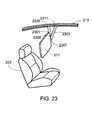
- FIG. 22provides a perspective view of a synchronized display attached to a single guide track via a single, side mounted linkage arm;
- FIG. 23provides a perspective view of a synchronized display attached to a single guide track via a pair of side mounted linkage arms.
- the present inventionprovides a system that monitors user position, more specifically the position of the user's seat, and automatically controls and adjusts the position of the system's display screen relative to the user, thereby helping to alleviate the eye strain, fatigue, neck and back pain that often accompany the improper use of a monitor for an extended period of time. While the primary application is an automobile, the inventors envision that the invention may be integrated equally well into an airplane, train, bus or other vehicle.
- FIG. 1illustrates the primary components associated with synchronized display system 100 .
- the systemincludes a seat 101 that is capable of being located in any of a variety of positions through the use of mechanical or electro-mechanical means 103 .
- the position of the seat, and therefore the user within the seat,is monitored using one or more position sensors 105 .
- Seat position information as determined by sensors 105is provided to control system 107 , also referred to herein simply as a controller.
- Control system 107which includes a control processor, may be a dedicated control system or integrated into another vehicle control system, for example a vehicle management system.
- System 100also includes a flat panel display 109 that can utilize any of a variety of display technologies (e.g., light-emitting diode (LED), plasma, organic light-emitting diode (OLED), liquid crystal (LCD), thin film transistor LCD (TFT-LCD), field emission display (FED) or other technology).
- Display 109may be intended solely for display purposes, i.e., a monitor, or display 109 may be a touch-screen that allows direct user interaction, for example by incorporating capacitive touch technology into the display.
- Display 109is coupled to a video source 111 (e.g., a computer, DVD player, etc.).
- a video source 111e.g., a computer, DVD player, etc.
- Video source 111may be hard-wired to the display via cabling 113 , or coupled via a wireless system 115 using any of a variety of wireless communication protocols (e.g., IEEE 802.11, long term evolution (LTE), Wi-Fi, Bluetooth, WiGig, WirelessHD, etc.).
- wireless communication protocolse.g., IEEE 802.11, long term evolution (LTE), Wi-Fi, Bluetooth, WiGig, WirelessHD, etc.
- a display position controller 117may utilize an electro-mechanical (e.g., motorized) positioner, a hydraulic positioner or other positioning system to adjust and control the viewing position of display 109 .
- display positioning system 117is used by the system controller 107 to vary the position of display 109 in response to movement of vehicle seat 101 .
- Sensors 119are used to insure proper placement of display 109 and as such, may either directly monitor display position or may determine display position by monitoring display positioning system 117 . In a preferred embodiment, sensors 119 and positioning system 117 are combined into a single system.
- control system 107monitors the status of display 109 and/or video source 111 .
- controller 107can be configured to automatically deploy display 109 from a storage position when the system is activated, and then return display 109 to its storage position when it is no longer required, i.e., when the display and/or video source is deactivated.
- control system 107may be coupled to one or more vehicle status sensors 123 that monitor whether or not the vehicle is operating (i.e., turned on) and/or whether or not the vehicle is currently in ‘drive’ or in ‘park’. The system can be configured to utilize this vehicle information to determine when to deploy or store display 109 , for example deploying display 109 when the car is turned on or placed into drive and then storing display 109 when the car is turned off or placed into park.
- a memory 121is coupled to system controller 107 .
- Memory 121may be a stand-alone memory or integrated into controller 107 .
- Memory 121may be comprised of flash memory, a solid state disk drive, a hard disk drive, or any other memory type or combination of memory types.
- Stored within memory 121is a set of control instructions which, in at least one embodiment, includes a look-up table that provides a particular display location, referred to herein as a compatible display position, for each position of vehicle seat 101 within a range of seat positions.
- each preset display position stored in memorymaintains at least one of (i) display viewing distance, (ii) display viewing height and/or (iii) display viewing angle within a preset range as the vehicle seat position is changed. Accordingly, when adjusting the display in response to a change in seat position, preferably controller 107 uses the look-up table to determine the compatible display position for the current seat position.
- FIGS. 2-5illustrate a preferred embodiment of the invention.
- FIG. 2provides a side view of the primary vehicle components involved in a system utilizing the synchronized display of the invention. Visible in this figure is a front seat 201 , a rear seat 203 , the front windshield 205 and the vehicle's roof headliner 207 . Stored within a recess 209 of the headliner is a display 211 , although it should be understood that display 211 may be stored in other locations such as adjacent to the headliner but not within the headliner, adjacent to the sunroof, adjacent to the sunroof and within the sunroof pocket, in the rear deck, or elsewhere.
- display 211is linked to a guide track 213 via linkage 217 , track 213 preferably hidden from sight by locating it between the headliner 207 and the roof 215 .
- Display linkage 217preferably passes through a slot or slots in headliner 207 .
- control system 107 and display position controller 117move display 211 into a display position compatible to the current position of viewing seat 203 . If seat 203 is in a typical upright position as shown in FIG. 3 , display 211 is automatically moved into position by rotating link 217 about axis 301 , moving link 217 within track 213 , rotating link 303 about axis 305 , and rotating display 211 about axis 307 , thereby placing display 211 at the right distance 309 from seat 203 and the person sitting within the seat. If the user alters the position of seat 203 , for example by reclining as shown in FIG. 4 , control system 107 monitors the movement of the seat using sensors 105 .
- control system 107Based on the new location of seat 105 , control system 107 automatically moves display 211 into position by once again rotating link 217 about axis 301 , moving link 217 within track 213 , rotating link 303 about axis 305 , and rotating display 211 about axis 307 . Since control system 107 continually monitors for seat movement/position, if the user once again alters the position of seat 203 , for example moving seat 203 into a full recline as shown in FIG. 5 , then control system will again move display 211 into position, thereby maintaining the distance 309 between the display panel 211 and the seat 203 .
- control system 107monitors seat position and automatically repositions display 211 in order to maintain the desired relationship between the display and the seat's occupant, thereby reducing eye strain, fatigue, neck and back pain. In a preferred configuration control system 107 does not initiate display movement until after seat movement has stopped, resulting in fluid movement of the display relative to the vehicle's occupants. Alternately, the system can be configured to allow control system 107 to initiate display movement as soon as seat movement is detected.
- control system 107returns display 211 to recess 209 (or to a different designated storage area) when the vehicle is turned off.
- the systemcan also be set-up to return the display to its storage area (e.g., recess 209 ) when the car is placed in park.
- the useris able to over-ride the system so that display 211 can be left in the optimum viewing position for the occupant of seat 203 even if the car is turned off or placed in park, thus allowing the occupant to continue to utilize the display system.
- the userrather than having the system automatically return the display to its storage area, the user must command the system to return to storage, for example by de-activating the display system.
- FIG. 6illustrates that as seat 203 is moved backward from a first position 601 , shown in phantom, to a second, final position 603 , display 211 moves from a first position 605 , shown in phantom, to a second, final position 607 , thereby retaining the desired spacing between the display and the user.
- FIG. 6illustrates that as seat 203 is moved backward from a first position 601 , shown in phantom, to a second, final position 603 , display 211 moves from a first position 605 , shown in phantom, to a second, final position 607 , thereby retaining the desired spacing between the display and the user.
- FIG. 6illustrates that as seat 203 is moved backward from a first position 601 , shown in phantom, to a second, final position 603 , display 211 moves from a first position 605 , shown in phantom, to a second, final position 607 , thereby retaining the desired
- FIG. 7illustrates that as seat 203 is moved downward from a first position 701 , shown in phantom, to a second, final position 703 , display 211 moves from a first position 705 , shown in phantom, to a second, final position 707 .
- viewing distancewas kept constant, or at least kept within a preset viewing distance range
- the inventionmay be used to insure that other display characteristics are kept constant, or within an acceptable range, during seat motion.
- the display viewing height 803 and display viewing angle 805may also be preset.
- control system 107maintains these settings within an acceptable range for the new seat position.
- Viewing distance 801 , viewing height 803 and viewing angle 805may be preset by the manufacturer or by a third party (e.g., a service technician).
- the end usermay input one or more of these viewing preferences into the system, thus allowing the user to personalize the system to insure that the viewing criteria properly take into account the user's physical size, viewing preferences and/or visual acuity.
- these viewing preferencesare input by the user upon system initialization by manually adjusting display 211 to the desired distance, height and angle. After this initial set-up, control system 107 adjusts the position of display 211 to maintain these preferences each time the seat is moved.
- the userinputs their viewing preferences using a user interface 901 (see FIG. 9 ) that is coupled to control system 107 .
- User interface 901may be a stand-alone interface, or integrated into the vehicle's user interface.
- FIGS. 10-13provide the same views as FIGS. 2-5 but illustrate an alternate positioning system that utilizes a telescoping link 1001 in order to maintain viewing distance 1101 , or other display criteria, as the position of seat 203 is varied by the user.
- link 1001is controllably pivoted about pivot axes 1003 and 1005 .
- FIGS. 14-17illustrate yet another positioning system, this embodiment utilizing a telescoping link 1401 that controllably pivots about axes 1403 and 1405 .
- link 1401has limited range in order to achieve a greater degree of link stability.
- position controller 117is able to move link 1401 within guide track 213 .
- FIGS. 2-8 and 10-17are illustrated with a car's rear passenger seat, the display system of the invention is equally applicable to other vehicle seats (e.g., front passenger seat) as well as other types of vehicles (e.g., trains, buses, airplanes, etc.). Additionally, even though in the exemplary embodiments only a single link is visibly coupled to display 211 , it should be understood that one or more links may be coupled to the display, and that the linkage assembly may be coupled to the center of the display, to one or both sides of the display, or to multiple locations on the display. To further clarify the invention, FIGS.
- FIGS. 18-22illustrate some exemplary coupling techniques that may be used to couple the linkage assembly to display 211 and to guide track 213 .
- the exemplary coupling techniques shown in these figuresmay also be used with a multi-link, multi-pivoting assembly as shown in FIGS. 2-8 or with a telescoping link(s) as shown in FIGS. 10-17 .
- display 211is attached to guide track 213 via a single, centrally located arm 1801 .
- Display 211pivots relative to arm 1801 about hinge 1803 , while arm 1801 pivots relative to guide track 213 about hinge 1805 .
- display 211is attached to guide track 213 via a pair of centrally located arms 1901 and 1903 .
- Display 211pivots relative to arm 1901 about hinge 1905 and relative to arm 1903 about hinge 1907 .
- Arm 1901pivots relative to guide track 213 about hinge 1909 while arm 1903 pivots relative to guide track 213 about hinge 1911 .
- display 211is attached to a pair of guide tracks 213 A/ 213 B via a pair of side mounted arms 2001 and 2003 .
- Display 211pivots relative to arm 2001 about hinge 2005 and relative to arm 2003 about hinge 2007 .
- Arm 2001pivots relative to guide track 213 A about hinge 2009 .
- the hinge coupling at location 2011allows arm 2003 to pivot relative to guide track 213 B.
- display 211is attached to a first guide track 213 A via a first pair of side mounted arms 2101 and 2103 , and to a second guide track 213 B via a second pair of side mounted arms 2105 and 2107 .
- Display 211pivots relative to arm 2101 about a hinge not visible in this view; pivots relative to arm 2103 about hinge 2109 ; pivots relative to arm 2105 about hinge 2111 ; and pivots relative to arm 2107 about hinge 2113 .
- Arm 2101pivots relative to guide track 213 A about hinge 2115 ; arm 2103 pivots relative to guide track 213 A about hinge 2117 ; arm 2105 pivots relative to guide track 213 B about a hinge (not visible in this view) at location 2119 ; and arm 2107 pivots relative to guide track 213 B about a hinge (not visible in this view) at location 2121 .
- display 211is attached to guide track 213 via a single, side mounted arm 2201 .
- Display 211pivots relative to arm 2201 about hinge 2203 , while arm 2201 pivots relative to guide track 213 about hinge 2205 .
- display 211is attached to guide track 213 via a pair of side mounted located arms 2301 and 2303 .
- Display 211pivots relative to arm 2301 about hinge 2305 (partially visible in this view) and relative to arm 2303 about hinge 2307 (partially visible in this view).
- Arm 2301pivots relative to guide track 213 about hinge 2309 while arm 2303 pivots relative to guide track 213 about hinge 2311 .
Landscapes
- Engineering & Computer Science (AREA)
- Mechanical Engineering (AREA)
- Theoretical Computer Science (AREA)
- Aviation & Aerospace Engineering (AREA)
- Transportation (AREA)
- Human Computer Interaction (AREA)
- Physics & Mathematics (AREA)
- General Engineering & Computer Science (AREA)
- General Physics & Mathematics (AREA)
- Fittings On The Vehicle Exterior For Carrying Loads, And Devices For Holding Or Mounting Articles (AREA)
- Seats For Vehicles (AREA)
- Devices For Indicating Variable Information By Combining Individual Elements (AREA)
Abstract
Description
Claims (18)
Priority Applications (6)
| Application Number | Priority Date | Filing Date | Title |
|---|---|---|---|
| US14/082,241US9442688B2 (en) | 2013-11-18 | 2013-11-18 | Synchronized display system |
| US14/082,495US20150138448A1 (en) | 2013-11-18 | 2013-11-18 | Adjustable Display System for Vehicular Use |
| JP2014224459AJP5984124B2 (en) | 2013-11-18 | 2014-11-04 | Synchronous display system |
| EP14193270.7AEP2873563B1 (en) | 2013-11-18 | 2014-11-14 | Synchronized display system |
| CN201420692983.5UCN204623328U (en) | 2013-11-18 | 2014-11-18 | Display positioning system |
| CN201410658892.4ACN104648266B (en) | 2013-11-18 | 2014-11-18 | Synchronized Display System |
Applications Claiming Priority (1)
| Application Number | Priority Date | Filing Date | Title |
|---|---|---|---|
| US14/082,241US9442688B2 (en) | 2013-11-18 | 2013-11-18 | Synchronized display system |
Related Child Applications (1)
| Application Number | Title | Priority Date | Filing Date |
|---|---|---|---|
| US14/082,495Continuation-In-PartUS20150138448A1 (en) | 2013-11-18 | 2013-11-18 | Adjustable Display System for Vehicular Use |
Publications (2)
| Publication Number | Publication Date |
|---|---|
| US20150138043A1 US20150138043A1 (en) | 2015-05-21 |
| US9442688B2true US9442688B2 (en) | 2016-09-13 |
Family
ID=52003564
Family Applications (1)
| Application Number | Title | Priority Date | Filing Date |
|---|---|---|---|
| US14/082,241Active2034-07-13US9442688B2 (en) | 2013-11-18 | 2013-11-18 | Synchronized display system |
Country Status (4)
| Country | Link |
|---|---|
| US (1) | US9442688B2 (en) |
| EP (1) | EP2873563B1 (en) |
| JP (1) | JP5984124B2 (en) |
| CN (2) | CN104648266B (en) |
Cited By (3)
| Publication number | Priority date | Publication date | Assignee | Title |
|---|---|---|---|---|
| US11358450B2 (en) | 2019-03-15 | 2022-06-14 | Webasto SE | Apparatus and method for adjusting a screen arrangement for a vehicle roof, and vehicle roof for a motor vehicle |
| US20220324575A1 (en)* | 2021-04-07 | 2022-10-13 | B/E Aerospace, Inc. | Virtual open sky in super first-class suites |
| US20220388457A1 (en)* | 2019-11-26 | 2022-12-08 | Bayerische Motoren Werke Aktiengesellschaft | Display Device, Vehicle and Method for Operating a Display Device |
Families Citing this family (31)
| Publication number | Priority date | Publication date | Assignee | Title |
|---|---|---|---|---|
| US9442688B2 (en)* | 2013-11-18 | 2016-09-13 | Atieva, Inc. | Synchronized display system |
| TWM487864U (en)* | 2014-03-14 | 2014-10-11 | Chi-Yuan Wen | Vision dead angle display device for vehicle front pillar |
| JP6319349B2 (en)* | 2015-04-03 | 2018-05-09 | 株式会社デンソー | Information presentation device |
| US10860752B2 (en)* | 2015-08-25 | 2020-12-08 | Dassault Systémes Americas Corp. | Method and system for vision measure for digital human models |
| US10101775B2 (en)* | 2016-08-22 | 2018-10-16 | Faraday&Future Inc. | Automatic display adjustment systems and methods |
| GB2563287B (en)* | 2017-06-09 | 2021-05-12 | Ford Global Tech Llc | A vehicle display system and method |
| KR101889043B1 (en)* | 2017-11-23 | 2018-08-20 | 현대자동차주식회사 | Vehicle and control method for the vehicle |
| CN118386996A (en) | 2018-01-04 | 2024-07-26 | 哈曼国际工业有限公司 | Ambient sunroof for an enhanced media experience in the cabin |
| DE102018212604A1 (en)* | 2018-07-27 | 2020-01-30 | Bayerische Motoren Werke Aktiengesellschaft | Display device and vehicle |
| DE102018212600A1 (en)* | 2018-07-27 | 2020-01-30 | Bayerische Motoren Werke Aktiengesellschaft | Display device and vehicle |
| FR3085644B1 (en)* | 2018-09-11 | 2020-10-16 | Psa Automobiles Sa | AUTOMOTIVE VEHICLE ROOF ROTATING ARM, WITH OBJECT SUPPORT AND INFLATABLE BAG PROTECTION DEVICE FOR A PASSENGER OF A SEAT |
| DE102018129479B4 (en)* | 2018-11-22 | 2025-01-16 | Webasto SE | Device and method for adjusting a display arrangement for a vehicle roof and vehicle roof for a motor vehicle |
| CN109677331A (en)* | 2019-01-31 | 2019-04-26 | 重庆长安汽车股份有限公司 | A kind of automobile-used Spatial Imaging System and automobile |
| EP3708432B1 (en)* | 2019-03-15 | 2022-05-04 | Webasto SE | Vehicle roof for a motor vehicle and device and method for adjusting a display assembly for a vehicle roof |
| DE102019106607A1 (en)* | 2019-03-15 | 2020-09-17 | Bayerische Motoren Werke Aktiengesellschaft | Device for presenting information in a vehicle by means of a display, as well as a vehicle roof |
| CN110182134A (en)* | 2019-05-05 | 2019-08-30 | 惠州市德赛西威智能交通技术研究院有限公司 | A kind of screen self-adaption regulation system and method |
| CN112406726B (en)* | 2019-08-23 | 2022-07-15 | 比亚迪股份有限公司 | Vehicle and display method and device therefor |
| KR102663989B1 (en)* | 2019-12-11 | 2024-05-07 | 현대자동차 주식회사 | Display moving device |
| KR102715251B1 (en)* | 2019-12-26 | 2024-10-10 | 엘지디스플레이 주식회사 | Display assembly |
| EP3845420B1 (en)* | 2019-12-30 | 2023-05-24 | Inalfa Roof Systems Group B.V. | Vehicle and roof construction including a display device for use therein |
| DE102020101719A1 (en)* | 2020-01-24 | 2021-07-29 | Bayerische Motoren Werke Aktiengesellschaft | Display device, vehicle and operating method for a display device |
| CN113401067B (en)* | 2020-03-16 | 2023-05-26 | 富顶精密组件(深圳)有限公司 | Automobile central control system and control method for controlling same |
| CN111596874A (en)* | 2020-04-09 | 2020-08-28 | 恒大新能源汽车投资控股集团有限公司 | Method, device and equipment for synchronously displaying associated information of vehicle-mounted terminal |
| DE102020113692A1 (en)* | 2020-05-20 | 2021-11-25 | Bayerische Motoren Werke Aktiengesellschaft | Vehicle and method for adapting a position of a display in the vehicle |
| CN112298059A (en)* | 2020-10-26 | 2021-02-02 | 武汉华星光电技术有限公司 | Vehicle-mounted display screen adjusting device and vehicle |
| CN114604183A (en) | 2020-12-03 | 2022-06-10 | 英纳法天窗系统集团有限公司 | Roof structure including display device and vehicle |
| CN114312593B (en)* | 2021-12-30 | 2024-03-08 | 重庆长安汽车股份有限公司 | Car roof structure of integrated curved surface folding screen |
| US11801801B1 (en) | 2022-05-20 | 2023-10-31 | Ford Global Technologies, Llc | Deployable cargo panel |
| CN115431890A (en)* | 2022-09-28 | 2022-12-06 | 东风汽车集团股份有限公司 | A control method, device, equipment and storage medium for a vehicle rear display screen |
| CN116279167A (en)* | 2023-03-24 | 2023-06-23 | 蔚来汽车科技(安徽)有限公司 | Method for adjusting the position of a vehicle-mounted display screen using a position adjustment device |
| CN116022039B (en)* | 2023-03-29 | 2023-06-09 | 长安新能源南京研究院有限公司 | Control method and system for secondary driving screen TV mode of vehicle, vehicle and storage medium |
Citations (20)
| Publication number | Priority date | Publication date | Assignee | Title |
|---|---|---|---|---|
| US5507556A (en) | 1994-11-04 | 1996-04-16 | Burns Aerospace Corporation | Seat including an automatically adjustable display screen assembly |
| US5670853A (en)* | 1994-12-06 | 1997-09-23 | Trw Vehicle Safety Systems Inc. | Method and apparatus for controlling vehicle occupant position |
| US20020003571A1 (en)* | 2000-03-02 | 2002-01-10 | Kenneth Schofield | Video mirror systems incorporating an accessory module |
| JP2002234399A (en) | 2001-02-09 | 2002-08-20 | Mazda Motor Corp | Display device for vehicles |
| JP2004216925A (en) | 2003-01-09 | 2004-08-05 | Denso Corp | On-vehicle device and control device |
| US20050140191A1 (en)* | 2003-12-11 | 2005-06-30 | Thomas Curran | Stowable seat mounted display screen |
| US6931596B2 (en)* | 2001-03-05 | 2005-08-16 | Koninklijke Philips Electronics N.V. | Automatic positioning of display depending upon the viewer's location |
| US20050222719A1 (en) | 2004-04-06 | 2005-10-06 | Denso Corporation | In-vehicle mount type AV system and program |
| US20060061008A1 (en)* | 2004-09-14 | 2006-03-23 | Lee Karner | Mounting assembly for vehicle interior mirror |
| US20060212197A1 (en)* | 2005-02-18 | 2006-09-21 | Nick Butler | In-vehicle multimedia system |
| US20060262189A1 (en)* | 2005-05-17 | 2006-11-23 | Boundy Timothy M | Overhead mountable sliding video display assembly and method |
| JP2007168494A (en) | 2005-12-19 | 2007-07-05 | Fujitsu Ten Ltd | Information output device |
| JP2008279155A (en) | 2007-05-14 | 2008-11-20 | Panasonic Corp | Image display device |
| US20090085383A1 (en)* | 2007-10-01 | 2009-04-02 | Lear Corporation | Vehicle seat having an electronic display mounted thereon |
| JP2010025945A (en)* | 2009-10-07 | 2010-02-04 | Seiko Epson Corp | Vibrating gyro element, support structure of vibrating gyro element, and gyro sensor |
| US20100087951A1 (en) | 2008-10-08 | 2010-04-08 | Honda Motor Co., Ltd | Monitor postion adjustment device |
| JP2010125945A (en) | 2008-11-26 | 2010-06-10 | Yazaki Corp | Display installed vehicle |
| JP2010143318A (en) | 2008-12-17 | 2010-07-01 | Fujitsu Ten Ltd | Electric supply management device and electric supply management method |
| US20110227717A1 (en)* | 2008-11-25 | 2011-09-22 | Toyota Jidosha Kabushiki Kaisha | Vehicle display device and display method |
| US20120095643A1 (en)* | 2010-10-19 | 2012-04-19 | Nokia Corporation | Method, Apparatus, and Computer Program Product for Modifying a User Interface Format |
Family Cites Families (1)
| Publication number | Priority date | Publication date | Assignee | Title |
|---|---|---|---|---|
| US9442688B2 (en)* | 2013-11-18 | 2016-09-13 | Atieva, Inc. | Synchronized display system |
- 2013
- 2013-11-18USUS14/082,241patent/US9442688B2/enactiveActive
- 2014
- 2014-11-04JPJP2014224459Apatent/JP5984124B2/enactiveActive
- 2014-11-14EPEP14193270.7Apatent/EP2873563B1/enactiveActive
- 2014-11-18CNCN201410658892.4Apatent/CN104648266B/enactiveActive
- 2014-11-18CNCN201420692983.5Upatent/CN204623328U/ennot_activeExpired - Lifetime
Patent Citations (21)
| Publication number | Priority date | Publication date | Assignee | Title |
|---|---|---|---|---|
| US5507556A (en) | 1994-11-04 | 1996-04-16 | Burns Aerospace Corporation | Seat including an automatically adjustable display screen assembly |
| US5670853A (en)* | 1994-12-06 | 1997-09-23 | Trw Vehicle Safety Systems Inc. | Method and apparatus for controlling vehicle occupant position |
| US20020003571A1 (en)* | 2000-03-02 | 2002-01-10 | Kenneth Schofield | Video mirror systems incorporating an accessory module |
| JP2002234399A (en) | 2001-02-09 | 2002-08-20 | Mazda Motor Corp | Display device for vehicles |
| US6931596B2 (en)* | 2001-03-05 | 2005-08-16 | Koninklijke Philips Electronics N.V. | Automatic positioning of display depending upon the viewer's location |
| JP2004216925A (en) | 2003-01-09 | 2004-08-05 | Denso Corp | On-vehicle device and control device |
| US20050140191A1 (en)* | 2003-12-11 | 2005-06-30 | Thomas Curran | Stowable seat mounted display screen |
| US20050222719A1 (en) | 2004-04-06 | 2005-10-06 | Denso Corporation | In-vehicle mount type AV system and program |
| US20060061008A1 (en)* | 2004-09-14 | 2006-03-23 | Lee Karner | Mounting assembly for vehicle interior mirror |
| US20060212197A1 (en)* | 2005-02-18 | 2006-09-21 | Nick Butler | In-vehicle multimedia system |
| US20060262189A1 (en)* | 2005-05-17 | 2006-11-23 | Boundy Timothy M | Overhead mountable sliding video display assembly and method |
| JP2007168494A (en) | 2005-12-19 | 2007-07-05 | Fujitsu Ten Ltd | Information output device |
| JP2008279155A (en) | 2007-05-14 | 2008-11-20 | Panasonic Corp | Image display device |
| US20100045088A1 (en) | 2007-05-14 | 2010-02-25 | Panasonic Corporation | Image display |
| US20090085383A1 (en)* | 2007-10-01 | 2009-04-02 | Lear Corporation | Vehicle seat having an electronic display mounted thereon |
| US20100087951A1 (en) | 2008-10-08 | 2010-04-08 | Honda Motor Co., Ltd | Monitor postion adjustment device |
| US20110227717A1 (en)* | 2008-11-25 | 2011-09-22 | Toyota Jidosha Kabushiki Kaisha | Vehicle display device and display method |
| JP2010125945A (en) | 2008-11-26 | 2010-06-10 | Yazaki Corp | Display installed vehicle |
| JP2010143318A (en) | 2008-12-17 | 2010-07-01 | Fujitsu Ten Ltd | Electric supply management device and electric supply management method |
| JP2010025945A (en)* | 2009-10-07 | 2010-02-04 | Seiko Epson Corp | Vibrating gyro element, support structure of vibrating gyro element, and gyro sensor |
| US20120095643A1 (en)* | 2010-10-19 | 2012-04-19 | Nokia Corporation | Method, Apparatus, and Computer Program Product for Modifying a User Interface Format |
Cited By (5)
| Publication number | Priority date | Publication date | Assignee | Title |
|---|---|---|---|---|
| US11358450B2 (en) | 2019-03-15 | 2022-06-14 | Webasto SE | Apparatus and method for adjusting a screen arrangement for a vehicle roof, and vehicle roof for a motor vehicle |
| US20220388457A1 (en)* | 2019-11-26 | 2022-12-08 | Bayerische Motoren Werke Aktiengesellschaft | Display Device, Vehicle and Method for Operating a Display Device |
| US11981266B2 (en)* | 2019-11-26 | 2024-05-14 | Bayerische Motoren Werke Aktiengesellschaft | Display device, vehicle and method for operating a display device |
| US20220324575A1 (en)* | 2021-04-07 | 2022-10-13 | B/E Aerospace, Inc. | Virtual open sky in super first-class suites |
| US11987360B2 (en)* | 2021-04-07 | 2024-05-21 | B/E Aerospace, Inc. | Virtual open sky in super first-class suites |
Also Published As
| Publication number | Publication date |
|---|---|
| US20150138043A1 (en) | 2015-05-21 |
| JP5984124B2 (en) | 2016-09-06 |
| CN104648266A (en) | 2015-05-27 |
| EP2873563B1 (en) | 2016-10-12 |
| CN204623328U (en) | 2015-09-09 |
| JP2015098317A (en) | 2015-05-28 |
| CN104648266B (en) | 2017-04-12 |
| EP2873563A1 (en) | 2015-05-20 |
Similar Documents
| Publication | Publication Date | Title |
|---|---|---|
| US9442688B2 (en) | Synchronized display system | |
| JP5994179B2 (en) | System, method and program for adjusting vehicle display based on user orientation | |
| US20150138448A1 (en) | Adjustable Display System for Vehicular Use | |
| US9371011B2 (en) | Seat cushion extension apparatus | |
| CN101374693B (en) | Seatback entertainment display system | |
| US20200189418A1 (en) | Rotatable seat configuration with multi-use table | |
| CN106476660B (en) | Seat adjustment for enhanced driver visibility | |
| CN208881707U (en) | Electrically Adjustable Display Mounts, Seats and Vehicles | |
| KR101576377B1 (en) | Reclining module for head rest | |
| JP7662960B2 (en) | Display System | |
| CN114514135B (en) | Display device, vehicle and operation method for display device | |
| US20200391669A1 (en) | Display system for a vehicle | |
| US20190118675A1 (en) | Apparatus and method for controlling headrest of vehicle seat | |
| JP2017065662A (en) | Reclining device of vehicular seat | |
| US12304364B2 (en) | Seat adjustment apparatus for mobility | |
| JP2011162007A (en) | Vehicle seat adjusting device | |
| US9144169B2 (en) | Monitor manipulator | |
| KR20230169783A (en) | Seat for vehicle | |
| JP6089797B2 (en) | Operation switch | |
| JP2011148450A (en) | Vehicle seat adjustment device | |
| CN116867674A (en) | Foldable mechanism in environment | |
| KR20050048239A (en) | Slope control seat for vehicles | |
| KR20250083300A (en) | Integrated control system for vehicle seat |
Legal Events
| Date | Code | Title | Description |
|---|---|---|---|
| AS | Assignment | Owner name:ATIEVA, INC., CALIFORNIA Free format text:ASSIGNMENT OF ASSIGNORS INTEREST;ASSIGNORS:RAWLINSON, PETER DORE;OBERS, ERIC;SIGNING DATES FROM 20131112 TO 20131114;REEL/FRAME:031618/0339 | |
| FEPP | Fee payment procedure | Free format text:PAYOR NUMBER ASSIGNED (ORIGINAL EVENT CODE: ASPN); ENTITY STATUS OF PATENT OWNER: SMALL ENTITY | |
| STCF | Information on status: patent grant | Free format text:PATENTED CASE | |
| AS | Assignment | Owner name:TRINITY CAPITAL FUND III, L. P., ARIZONA Free format text:INTELLECTUAL PROPERTY SECURITY AGREEMENT;ASSIGNOR:ATIEVA, INC;REEL/FRAME:042125/0897 Effective date:20170331 | |
| AS | Assignment | Owner name:YINLONG ELECTRIC VEHICLE (HK) GROUP LIMITED, HONG KONG Free format text:SECURITY INTEREST;ASSIGNORS:ATIEVA, INC.;ATIEVA USA, INC;REEL/FRAME:044457/0942 Effective date:20171027 Owner name:YINLONG ELECTRIC VEHICLE (HK) GROUP LIMITED, HONG Free format text:SECURITY INTEREST;ASSIGNORS:ATIEVA, INC.;ATIEVA USA, INC;REEL/FRAME:044457/0942 Effective date:20171027 | |
| AS | Assignment | Owner name:AVB METRICS, LLC, CALIFORNIA Free format text:RELEASE BY SECURED PARTY;ASSIGNOR:TRINITY CAPITAL FUND III, L.P.;REEL/FRAME:047529/0619 Effective date:20180912 Owner name:ATIEVA USA, INC., CALIFORNIA Free format text:RELEASE BY SECURED PARTY;ASSIGNOR:TRINITY CAPITAL FUND III, L.P.;REEL/FRAME:047529/0619 Effective date:20180912 Owner name:ATIEVA, INC., CAYMAN ISLANDS Free format text:RELEASE BY SECURED PARTY;ASSIGNOR:TRINITY CAPITAL FUND III, L.P.;REEL/FRAME:047529/0619 Effective date:20180912 | |
| AS | Assignment | Owner name:AVB METRICS, LLC, CALIFORNIA Free format text:RELEASE BY SECURED PARTY;ASSIGNOR:YINLONG ELECTRIC VEHICLE (HK) GROUP LIMITED;REEL/FRAME:047620/0451 Effective date:20180914 Owner name:ATIEVA, INC., CAYMAN ISLANDS Free format text:RELEASE BY SECURED PARTY;ASSIGNOR:YINLONG ELECTRIC VEHICLE (HK) GROUP LIMITED;REEL/FRAME:047620/0451 Effective date:20180914 Owner name:ATIEVA USA, INC., CALIFORNIA Free format text:RELEASE BY SECURED PARTY;ASSIGNOR:YINLONG ELECTRIC VEHICLE (HK) GROUP LIMITED;REEL/FRAME:047620/0451 Effective date:20180914 | |
| AS | Assignment | Owner name:AYAR THIRD INVESTMENT COMPANY, SAUDI ARABIA Free format text:SECURITY INTEREST;ASSIGNOR:ATIEVA, INC.;REEL/FRAME:047199/0221 Effective date:20180916 | |
| AS | Assignment | Owner name:ATIEVA, INC., CALIFORNIA Free format text:RELEASE BY SECURED PARTY;ASSIGNOR:AYAR THIRD INVESTMENT COMPANY;REEL/FRAME:048811/0472 Effective date:20190402 | |
| MAFP | Maintenance fee payment | Free format text:PAYMENT OF MAINTENANCE FEE, 4TH YR, SMALL ENTITY (ORIGINAL EVENT CODE: M2551); ENTITY STATUS OF PATENT OWNER: SMALL ENTITY Year of fee payment:4 | |
| MAFP | Maintenance fee payment | Free format text:PAYMENT OF MAINTENANCE FEE, 8TH YR, SMALL ENTITY (ORIGINAL EVENT CODE: M2552); ENTITY STATUS OF PATENT OWNER: SMALL ENTITY Year of fee payment:8 |