US9442089B2 - Analyte meter test strip detection - Google Patents
Analyte meter test strip detectionDownload PDFInfo
- Publication number
- US9442089B2 US9442089B2US14/138,820US201314138820AUS9442089B2US 9442089 B2US9442089 B2US 9442089B2US 201314138820 AUS201314138820 AUS 201314138820AUS 9442089 B2US9442089 B2US 9442089B2
- Authority
- US
- United States
- Prior art keywords
- strip
- analyte meter
- analyte
- test strip
- detect signal
- Prior art date
- Legal status (The legal status is an assumption and is not a legal conclusion. Google has not performed a legal analysis and makes no representation as to the accuracy of the status listed.)
- Expired - Fee Related, expires
Links
- 239000012491analyteSubstances0.000titleclaimsabstractdescription82
- 238000012360testing methodMethods0.000titleclaimsabstractdescription81
- 238000001514detection methodMethods0.000titledescription5
- 238000005259measurementMethods0.000claimsdescription39
- 238000000034methodMethods0.000claimsdescription15
- 230000004044responseEffects0.000claimsdescription7
- 239000003990capacitorSubstances0.000claimsdescription5
- 238000004458analytical methodMethods0.000claims3
- 238000012544monitoring processMethods0.000claims1
- 239000008280bloodSubstances0.000description19
- 210000004369bloodAnatomy0.000description19
- WQZGKKKJIJFFOK-GASJEMHNSA-NGlucoseNatural productsOC[C@H]1OC(O)[C@H](O)[C@@H](O)[C@@H]1OWQZGKKKJIJFFOK-GASJEMHNSA-N0.000description17
- WQZGKKKJIJFFOK-VFUOTHLCSA-Nbeta-D-glucoseChemical compoundOC[C@H]1O[C@@H](O)[C@H](O)[C@@H](O)[C@@H]1OWQZGKKKJIJFFOK-VFUOTHLCSA-N0.000description17
- 239000008103glucoseSubstances0.000description17
- 239000000523sampleSubstances0.000description15
- 238000004891communicationMethods0.000description12
- 238000003556assayMethods0.000description9
- 238000012545processingMethods0.000description8
- 238000013523data managementMethods0.000description7
- 230000004913activationEffects0.000description5
- 230000005540biological transmissionEffects0.000description5
- 239000003153chemical reaction reagentSubstances0.000description5
- 238000003780insertionMethods0.000description5
- 230000037431insertionEffects0.000description5
- 230000008569processEffects0.000description5
- MMXZSJMASHPLLR-UHFFFAOYSA-Npyrroloquinoline quinoneChemical compoundC12=C(C(O)=O)C=C(C(O)=O)N=C2C(=O)C(=O)C2=C1NC(C(=O)O)=C2MMXZSJMASHPLLR-UHFFFAOYSA-N0.000description4
- 238000010586diagramMethods0.000description3
- 230000006870functionEffects0.000description3
- 108090000790EnzymesProteins0.000description2
- 102000004190EnzymesHuman genes0.000description2
- 108010050375Glucose 1-DehydrogenaseProteins0.000description2
- 230000010267cellular communicationEffects0.000description2
- 230000008859changeEffects0.000description2
- 229940088598enzymeDrugs0.000description2
- 235000019162flavin adenine dinucleotideNutrition0.000description2
- 239000011714flavin adenine dinucleotideSubstances0.000description2
- 230000002641glycemic effectEffects0.000description2
- 230000003287optical effectEffects0.000description2
- 239000013307optical fiberSubstances0.000description2
- 239000000725suspensionSubstances0.000description2
- 201000004569BlindnessDiseases0.000description1
- 208000024172Cardiovascular diseaseDiseases0.000description1
- 208000002249Diabetes ComplicationsDiseases0.000description1
- 108010015776Glucose oxidaseProteins0.000description1
- 239000004366Glucose oxidaseSubstances0.000description1
- 241001465754MetazoaSpecies0.000description1
- 208000028389Nerve injuryDiseases0.000description1
- 230000003213activating effectEffects0.000description1
- 230000006978adaptationEffects0.000description1
- 239000012805animal sampleSubstances0.000description1
- 239000006227byproductSubstances0.000description1
- 230000001413cellular effectEffects0.000description1
- 238000004590computer programMethods0.000description1
- 230000009849deactivationEffects0.000description1
- 206010012601diabetes mellitusDiseases0.000description1
- 230000002255enzymatic effectEffects0.000description1
- YAGKRVSRTSUGEY-UHFFFAOYSA-NferricyanideChemical compound[Fe+3].N#[C-].N#[C-].N#[C-].N#[C-].N#[C-].N#[C-]YAGKRVSRTSUGEY-UHFFFAOYSA-N0.000description1
- VWWQXMAJTJZDQX-UYBVJOGSSA-Nflavin adenine dinucleotideChemical compoundC1=NC2=C(N)N=CN=C2N1[C@@H]([C@H](O)[C@@H]1O)O[C@@H]1CO[P@](O)(=O)O[P@@](O)(=O)OC[C@@H](O)[C@@H](O)[C@@H](O)CN1C2=NC(=O)NC(=O)C2=NC2=C1C=C(C)C(C)=C2VWWQXMAJTJZDQX-UYBVJOGSSA-N0.000description1
- 229940093632flavin-adenine dinucleotideDrugs0.000description1
- 150000002303glucose derivativesChemical class0.000description1
- 229940116332glucose oxidaseDrugs0.000description1
- 235000019420glucose oxidaseNutrition0.000description1
- 238000005534hematocritMethods0.000description1
- 208000017169kidney diseaseDiseases0.000description1
- 239000007788liquidSubstances0.000description1
- 238000012423maintenanceMethods0.000description1
- 238000007726management methodMethods0.000description1
- 239000000463materialSubstances0.000description1
- 238000012986modificationMethods0.000description1
- 230000004048modificationEffects0.000description1
- 230000008764nerve damageEffects0.000description1
- 239000012811non-conductive materialSubstances0.000description1
- 210000002381plasmaAnatomy0.000description1
- 239000004065semiconductorSubstances0.000description1
- 210000002966serumAnatomy0.000description1
- 239000000243solutionSubstances0.000description1
- 210000003813thumbAnatomy0.000description1
Images


Classifications
- G—PHYSICS
- G01—MEASURING; TESTING
- G01N—INVESTIGATING OR ANALYSING MATERIALS BY DETERMINING THEIR CHEMICAL OR PHYSICAL PROPERTIES
- G01N27/00—Investigating or analysing materials by the use of electric, electrochemical, or magnetic means
- G01N27/26—Investigating or analysing materials by the use of electric, electrochemical, or magnetic means by investigating electrochemical variables; by using electrolysis or electrophoresis
- G01N27/28—Electrolytic cell components
- G01N27/30—Electrodes, e.g. test electrodes; Half-cells
- G01N27/307—Disposable laminated or multilayered electrodes
- G—PHYSICS
- G01—MEASURING; TESTING
- G01N—INVESTIGATING OR ANALYSING MATERIALS BY DETERMINING THEIR CHEMICAL OR PHYSICAL PROPERTIES
- G01N33/00—Investigating or analysing materials by specific methods not covered by groups G01N1/00 - G01N31/00
- G01N33/48—Biological material, e.g. blood, urine; Haemocytometers
- G01N33/483—Physical analysis of biological material
- G01N33/487—Physical analysis of biological material of liquid biological material
- G01N33/48785—Electrical and electronic details of measuring devices for physical analysis of liquid biological material not specific to a particular test method, e.g. user interface or power supply
Definitions
- This applicationgenerally relates to the field of blood analyte measurement systems and more specifically to a portable analyte meter that is configured to efficiently detect insertion of a test strip into a strip port circuit without adding unnecessary switching devices to the circuit.
- Blood glucose measurement systemstypically comprise an analyte meter that is configured to receive a biosensor, usually in the form of a test strip. Because many of these systems are portable, and testing can be completed in a short amount of time, patients are able to use such devices in the normal course of their daily lives without significant interruption to their personal routines.
- a person with diabetesmay measure their blood glucose levels several times a day as a part of a self management process to ensure glycemic control of their blood glucose within a target range.
- a failure to maintain target glycemic controlcan result in serious diabetes-related complications, including cardiovascular disease, kidney disease, nerve damage and blindness.
- test metersportable electronic analyte measurement devices
- electrical contacts in the meterestablish connections with contact pads on the test strip, which cause a voltage fluctuation in a detection circuit of the meter.
- This resulting voltage changesignals the microcontroller in the meter to activate resident electronic circuits as part of a “wake up” sequence in preparation for performing an assay when a sample is applied to the inserted test strip.
- electronic switches in the meterdisconnect, or deactivate, the detection circuit in order to change over from a test strip detection mode to an analyte measurement mode.
- the electronic switchesthemselves draw, or leak, current even when they are deactivated which creates an unwanted noise source during the analyte measurement.
- the very small level of electric current that is generated and analyzed during an assay sequencemay be affected by these leakage currents.
- it would be advantageous to implement a more efficient detection circuitthat does not require devices that inherently leak current.
- FIG. 1Aillustrates a diagram of an exemplary test strip based blood analyte measurement system
- FIG. 1Billustrates a diagram of an exemplary processing system of the test strip based blood analyte measurement system of FIG. 1A ;
- FIG. 2illustrates a diagram of another exemplary processing system of the test strip based blood analyte measurement system of FIG. 1A ;
- FIGS. 3A-3Billustrate an operational graph of the voltage levels monitored by the exemplary processing system of FIG. 2 ;
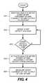
- FIG. 4illustrates a flow chart of a process performed by the exemplary processing system of FIG. 2 .
- patientor “user” refer to any human or animal subject and are not intended to limit the systems or methods to human use, although use of the subject invention in a human patient represents a preferred embodiment.
- samplemeans a volume of a liquid, solution or suspension, intended to be subjected to qualitative or quantitative determination of any of its properties, such as the presence or absence of a component, the concentration of a component, e.g., an analyte, etc.
- the embodiments of the present inventionare applicable to human and animal samples of whole blood. Typical samples in the context of the present invention as described herein include blood, plasma, serum, suspensions thereof, and haematocrit.
- analyte measurement system 100that includes an analyte (or test) meter 10 .
- the analyte meter 10is defined by a housing 11 having an interior that is sufficiently sized to retain a data management unit 150 ( FIG. 1B ), the housing having a test strip port 22 for receiving a test strip 24 .
- the analyte meter 10may be a blood glucose meter and the test strip 24 is provided in the form of a glucose test strip 24 inserted into the test strip port 22 for performing blood glucose measurements.
- the analyte meter 10further includes a plurality of user interface buttons, or keypad, 16 , 26 , and a display 14 , each disposed on a front facing side of the housing 14 , and a data port 13 disposed on one side of the housing opposite the test strip port 22 , as illustrated in FIG. 1A .
- a predetermined number of glucose test stripsmay be stored in the housing 11 and made accessible for use in blood glucose testing.
- the plurality of user interface buttons 16can be configured to allow the entry of data, to prompt an output of data, to navigate menus presented on the display 14 , and to execute commands.
- Output datacan include, for example, values representative of an analyte concentration that are presented on the display 14 .
- buttons 16include markings, e.g., up-down arrows, text characters “OK”, etc, which allow a user to navigate through the user interface presented on the display 14 .
- the buttons 16are shown herein as separate switches, a touch screen interface on display 14 with virtual buttons may also be utilized.
- the electronic components of the glucose measurement system 100can be disposed on, for example, a printed circuit board situated within the housing 11 and forming the data management unit 150 of the herein described system.
- FIG. 1Billustrates, in simplified schematic form, several of the electronic sub-systems disposed within the housing 11 for purposes of this embodiment.
- the data management unit 150includes a processing unit 50 in the form of a microprocessor, a microcontroller, an application specific integrated circuit (“ASIC”), a mixed signal processor (“MSP”), a field programmable gate array (“FPGA”), or a combination thereof, and is electrically connected to various electronic modules included on, or connected to, the printed circuit board, as will be described below.
- ASICapplication specific integrated circuit
- MSPmixed signal processor
- FPGAfield programmable gate array
- the microcontroller 50may be electrically connected to the test strip port connector (“SPC”) 70 positioned in the test strip port 22 via an analog front end sub-system 90 .
- the analog front end 90is electrically connected to the SPC 70 and to the microcontroller 50 during blood glucose testing.
- the SPC 70is configured to detect a resistance or impedance across electrodes disposed on the analyte test strip 24 , which are electrically connected to an applied blood sample disposed in a sample chamber therein.
- the sample chamberforms an electrochemical cell together with the sample and, using a potentiostat or transimpedance amplifier, the microcontroller 50 converts an electric current measurement into digital form for presentation on the display 14 , typically in units of milligrams per deciliter (mg/dl) or millimoles per liter (mmol/l).
- the microcontroller 50can be configured to receive input from and to transmit signals to the SPC 70 via the analog front end circuit 90 , as will be described herein, and may also perform a portion of the potentiostat function and the current measurement function.
- the test strip 24can be in the form of an electrochemical glucose test strip.
- the test strip 24can include one or more layers made from non-conductive material, such as an inert or support material that provides structural rigidity, and further one or more conductive layers comprising working and counter electrodes disposed thereon.
- Test strip 24can also include a plurality of electrical contact pads, where each electrode can be in electrical communication with at least one electrical contact pad.
- SPC 70can be configured to electrically engage the electrical contact pads using flexible conductive contacts, or prongs, and form electrical communication with the electrodes.
- Test strip 24can include a reagent layer that is disposed over at least one electrode forming part of the electrochemical cell of the test strip 24 .
- the reagent layercan include an enzyme and a mediator.
- Exemplary enzymes suitable for use in the reagent layerinclude glucose oxidase, glucose dehydrogenase (with pyrroloquinoline quinone co-factor, “PQQ”), and glucose dehydrogenase (with flavin adenine dinucleotide co-factor, “FAD”).
- An exemplary mediator suitable for use in the reagent layerincludes ferricyanide, which in this case is in the oxidized form.
- the reagent layercan be configured to physically transform glucose into an enzymatic by-product and in the process generate an amount of reduced mediator (e.g., ferrocyanide) that is proportional to the glucose concentration.
- the working electrode, or electrodescan then be used to measure a concentration of the reduced mediator in the form of a current magnitude.
- microcontroller 50can convert the current magnitude into a glucose concentration.
- An exemplary analyte meter performing such current measurementsis described in U.S. Patent Application Publication No. US 2009/0301899 A1 entitled “System and Method for Measuring an Analyte in a Sample”, which is incorporated by reference herein as if fully set forth in this application.
- a display module 58which may include a display processor and display buffer, is electrically connected to the microcontroller 50 over the communication interface 57 for receiving and displaying output data, and for displaying user interface input options under control of the microcontroller 50 .
- the display interfaceis accessible via the microcontroller 50 for presenting menu options to a user of the blood glucose measurement system 100 .
- User input module 64may receive responsive inputs from the user manipulating buttons, or keypad 16 , which are processed and transmitted to the microcontroller 50 over the communication interface 63 .
- the microcontroller 50may have electrical access to a digital time-of-day clock connected to the printed circuit board for recording dates and times of blood glucose measurements and user inputs, which may then be accessed, uploaded, or displayed at a later time as necessary.
- a communications module 60may include transceiver circuits for wireless digital data transmission and reception, and is electrically connected to the microcontroller 50 over communication interface 59 .
- the wireless transceiver circuitsmay be in the form of integrated circuit chips, chipsets, and programmable functions operable via microcontroller 50 using on-board memory, or a combination thereof.
- the wireless transceiver circuitsmay be compatible with different wireless transmission standards. For example, a wireless transceiver circuit may be compatible with the Wireless Local Area Network IEEE 802.11 standard known as WiFi.
- a transceiver circuitmay be configured to detect a WiFi access point in proximity to the analyte meter 10 and to transmit and receive data from such a detected WiFi access point.
- a wireless transceiver circuitmay be compatible with the Bluetooth protocol and is configured to detect and process data transmitted from a Bluetooth hub in proximity to the analyte meter 10 .
- a wireless transceiver circuitmay be compatible with the near field communication (“NFC”) standard and is configured to establish radio communication with, for example, an NFC compliant reader device capable of gathering analyte test measurements in proximity to the analyte meter 10 .
- NFCnear field communication
- a wireless transceiver circuitmay comprise a circuit for cellular communication with cellular networks and is configured to detect and link to available cellular communication towers.
- An on-board memory module 62that includes but is not limited to volatile random access memory (“RAM”), a non-volatile memory, which may comprise read only memory (“ROM”), non-volatile RAM (NVRAM), or flash memory, and may be connected to an external portable memory device via a data port 13 , is electrically connected to the microcontroller 50 over a communication interface 61 .
- External memory devicesmay include flash memory devices housed in thumb drives, portable hard disk drives, data cards, or any other form of electronic storage device.
- the on-board memorycan include various embedded applications and programs executed by the microcontroller 50 for operation of the analyte meter 10 , as explained herein.
- On board or external memorycan also be used to store a history of a user's blood glucose measurements including dates and times associated therewith.
- a power supply module 56is electrically connected to modules in the housing 11 and the microcontroller 50 to supply electric power thereto.
- the power supply module 56may comprise standard or rechargeable batteries, or an AC power supply that may be activated when the analyte meter 10 is connected to a source of AC power.
- the power supply module 56is electrically connected to the microcontroller 50 over the communication interface 55 such that microcontroller 50 can monitor a power level remaining in a battery of the power supply module 56 .
- the data port 13can be used to accept a suitable connector attached to a connecting lead, thereby allowing the analyte meter 10 to be wired to an external device such as a personal computer.
- Data port 13can be any port that allows for transmission of data, power, or a combination thereof, such as a serial, USB, or a parallel port.
- the strip port connector 70comprises at least two working electrode contacts 92 , 93 , and a strip-detect electrical contact 94 .
- the electrical contacts 92 - 94are each formed as prongs to connect electrically with a contact pad on the test strip 24 that is inserted into the strip port connector 70 .
- the strip port connector 70is configured to connect together the electrical contacts 92 and 94 , when the test strip 24 is inserted, through a switch bar 72 that connects to an electrode of an inserted test strip 24 .
- the switch bar 72generates a signal transmitted to the microcontroller 50 , indicating that a test strip 24 has been inserted in the strip port connector 70 , as will now be described.
- the working electrode contact 92is connected to an input of an operational amplifier (an op-amp) 80 and the output of the op amp is connected to the microcontroller 50 over a microcontroller interface 81 .
- a pull-down circuit 78e.g. a resistor and FET, is connected between the working electrode contact 92 and ground and is controlled, i.e. turned on and off, by a signal from the microcontroller 50 over an interface 79 .
- the strip-detect electrical contact 94is connected to the microcontroller 50 via another interface 82 , which is monitored by the microcontroller 50 for detecting that a test strip has been inserted into strip port connector 70 .
- a pull-up circuit 76e.g. a resistor and FET, is connected between strip-detect electrical contact 94 and a voltage source Vcc, which may be set at a predetermined voltage (e.g., about 3V), and is controlled, i.e., turned on and off, by a signal from the microcontroller 50 over another interface 77 .
- Vccvoltage source
- the microcontroller 50Prior to insertion of the test strip 24 into the strip port connector 70 , the microcontroller 50 is programmed to maintain the analyte measurement system 100 in a low power or passive “sleep” mode. During the low power mode, microcontroller 50 activates pull down circuit 78 and pull up circuit 76 , thereby connecting the working electrode contact 92 to the ground (logical 0) and the strip detect contact 94 is maintained at a higher voltage (logical 1) by being connected to voltage source V CC . Thus, the analog front end circuit 90 may be monitored by the microcontroller 50 as a “digital” input circuit. In practice, the resistor used in the pull-up circuit 76 is typically selected at about 100 kohm and the resistor used in the pull-down circuit 78 is typically selected at about 1 kohm.
- test strip 24When test strip 24 is inserted into strip port connector 70 , the immediate connection between the working electrode contact 92 and the strip-detect electrical contact 94 , via the switch bar 72 , switches the voltage at the strip detect interface 82 from high, e.g. about 3V equivalent to a logical 1, to low, e.g. about 0V equivalent to a logical 0.
- This voltage drop at the microcontroller input 82signals the microcontroller that the test strip 24 has been inserted into the strip port connector 70 .
- the microcontroller 50initiates a programmed “wake up” routine and activates the test meter 10 for performing a sample assay.
- Part of the activation routineincludes deactivating the pull-up and pull-down circuits 76 , 78 , via signals transmitted on interfaces 77 , 79 , respectively.
- the pull-up and pull-down circuits 76 , 78are not needed for performing the assay, however, their deactivation does not ensure that leakage currents through these devices are also shut off, particularly through the pull-down circuit 78 which is connected to the working electrode contact 92 .
- the analyte meter 10awaits application of a blood sample on the test strip 24 , whereafter a current measurement through the applied sample may take place using the working electrode contacts 92 , 93 , (and ground voltage reference contact 95 ) which are each connected to the microcontroller 50 through op amp circuits 74 , 80 , and microcontroller interfaces 75 , 81 , respectively.
- any leakage currents in the deactivated pull-up circuit 76 and pull-down circuit 78may affect the assay results obtained by introducing extraneous noise.
- an embodiment of an exemplary data management unit (DMU) 250 having the strip port connector 70 and a portion of analog front end circuit 190is illustrated, wherein like numbered elements operate substantially as explained above with reference to FIG. 1B , and are not repeated here for ease of description.
- the analog front end 190no longer includes pull-up and pull down circuits 76 , 78 , attached to the strip detect interface 82 or the working electrode contact 92 , thereby reducing cost of the DMU 250 and eliminating potential noise sources.
- the working electrode contact 92is connected to an inverting input of the op amp 80 and the output of the op amp is connected to the microcontroller 50 over microcontroller interface 81 .
- the microcontroller 50includes a switch 183 connected to the microcontroller interface 81 which may be selectively coupled by the microcontroller 50 to ground 184 .
- the strip-detect electrical contact 94is connected to the microcontroller 50 via interface 82 .
- the microcontrollerincludes a pull-up circuit 176 connected to the interface 82 which may be selectively activated by the microcontroller 50 to connect the strip-detect contact 94 to an internal power supply node comprising voltage source V DD , which may be set at about 3V.
- the microcontroller 50is programmed to maintain the analyte measurement system 100 in its low power “sleep” mode. During the low power mode, the microcontroller 50 activates the pull-up circuit 176 which energizes the strip detect interface 82 and the strip detect contact 94 . The microcontroller 50 further maintains the op amp 80 in an unpowered state and activates switch 183 to connect the microcontroller interface 81 to the ground 184 . A voltage source 178 is connected to a non-inverting input of the op amp 80 .
- the feedback circuitcomprises resistor 177 and capacitor 175 which, together with the op amp 80 and voltage source 178 , form a transimpedance amplifier that is operable during an active mode of the test meter 10 .
- the interface 82 of the analog front end circuit 190may be monitored by the microcontroller 50 as a “digital” input signal, similar in operation to the circuit of FIG. 1B described above circuit.
- the size of the capacitor 175may be selected at about 33 nF, the resistor 177 at about 220 kOhm, and the voltage source 178 may be set at about 400 mV, as an example.
- the connection between the working electrode contact 92 and the strip-detect electrical contact 94via the switch bar 72 , drops the voltage at the strip detect interface 82 from high, e.g. about 3V equivalent to a logical 1, to low, e.g. about 0V equivalent to a logical 0.
- This voltage drop at the microcontroller interface 82signals the microcontroller that the test strip 24 has been inserted into the strip port connector 70 .
- the microcontroller 50initiates a programmed “wake up” routine and activates the test meter 10 for performing a sample assay.
- Part of the activation routineincludes deactivating the pull-up switch 176 , powering the op amp 80 , and opening the switch 183 .
- the analyte meter 10awaits application of a blood sample on the test strip 24 , whereafter a current applied and measured through the sample may take place using the working electrode contacts 92 , 93 , which are each connected to the microcontroller 50 through op amp circuits 74 , 80 , and microcontroller interfaces 75 , 81 , respectively.
- the absence of the pull-up and pull-down circuits 76 , 78 , external to the microcontroller 50means that leakage currents generated thereby do not affect the sample assay current measurement at least at the microcontroller interface 81 .
- the test meter 10may be programmed to periodically poll the strip detect interface 82 to determine whether a test strip is inserted therein, e.g., at approximately 1 sec intervals. The polling takes place during a sleep mode of the test meter 10 by activating the pull up circuit 176 and measuring the voltage at the interface 82 after a preselected delay. As described above, and during sleep mode, the op amp 80 is unpowered and its output at microcontroller interface 81 is connected to ground by the switch 183 .
- FIGS. 3A-3Billustrate the strip detect voltage levels 302 , 303 , on interface 82 , as detected by the microcontroller 50 , when a test strip 24 is not inserted ( FIG. 3A ) into the strip port connector 70 and when a test strip 24 is inserted ( FIG. 3B ) into the strip port connector 70 , respectively.
- the polling sequencebegins at about 60 is wherein the pull-up circuit 176 is activated to connect the strip detect interface 82 to voltage source V DD , wherein the voltage level on the strip detect interface 82 rises immediately to about 3 V.
- the voltage level of the strip detect interface 82is sensed during an activation, i.e., high voltage level, of a microcontroller sense circuit measurement window 304 , i.e. from about 75 is to about 85 ⁇ s.
- the microcontrollersenses the high voltage level 302 of about 3 V (i.e. a logical or digital 1) of the strip detect interface 82 which indicates to the microcontroller 50 that a test strip has not been inserted in the strip port connector 70 , which causes the microcontroller 50 to maintain the test meter in the low power sleep mode until the next poll. Referring to FIG.
- the polling sequence for detecting an inserted test stripbegins at about 60 is wherein the pull-up circuit 176 is activated to connect the strip detect interface 82 to voltage source V DD , as just described.
- the voltage level of the strip detect interface 82is sensed during an activation, i.e., high voltage level, of a microcontroller sense circuit measurement window 304 , i.e. from about 75 is to about 85 ⁇ s.
- the microcontrollersenses the low voltage level 303 of about 0.2 V (i.e.
- a logical or digital 0) of the strip detect interface 82which indicates to the microcontroller 50 that a test strip has been inserted in the strip port connector 70 which causes the microcontroller 50 to initiate the wake-up activation sequence of the test meter 10 as described above.
- the preselected delay of about 15is after energizing the strip-detect signal interface 82 provides a time window 304 wherein the voltage level of the strip detect interface 82 is sufficiently differentiated as between the test-strip-not-inserted voltage level 302 and the test-strip-inserted voltage level 303 so that the microcontroller 50 can digitally (logic 0/1) distinguish the difference.
- the strip detect interface voltage 303continues to rise after insertion of the test strip 24 . Therefore, it is advantageous, for an accurate digital read, to measure the voltage level thereon earlier rather than later.
- FIG. 4there is illustrated a flow chart of a method of operating an embodiment of an analyte measurement system 100 .
- the analyte measurement system 100is maintained in a (default) low power inactive sleep mode. Maintenance of the sleep mode includes unpowering an op amp 80 of the test meter, such as by disconnecting or switching off its power supply and connecting an output of the op amp to ground 184 .
- a voltage level of a strip detect interface 82is periodically sensed by the analyte measurement system 100 .
- the analyte measurement system 100is programmed to continue periodically polling the strip detect interface 82 . If the sensed voltage level is at a low voltage level equivalent to a digital “zero”, the analyte measurement system 100 is programmed to activate an analog front end circuit 190 to perform an analyte measurement, step 404 , including powering the op amp such as by connecting it to, or switching on, its power supply and disconnecting its output from ground 184 . At step 405 , the analyte measurement is performed including measuring a magnitude of a current at the output 81 of the op amp 80 .
- aspects of the present inventionmay be embodied as a processing system, method, or apparatus. Accordingly, aspects of the present invention may take the form of an entirely hardware embodiment, an entirely software embodiment (including firmware, resident software, micro-code, etc.), or an embodiment combining software and hardware aspects that may all generally be referred to herein as a “circuit,” “circuitry,” “module,” ‘subsystem” and/or “system.” Furthermore, aspects of the present invention may take the form of a computer program product embodied in one or more computer readable medium(s) having computer readable program code embodied thereon.
- Program code and/or data representative of operations and measurements performedmay be stored using any appropriate medium, including but not limited to any combination of one or more computer readable medium(s).
- a computer readable storage mediummay be, for example, an electronic, magnetic, optical, electromagnetic, infrared, or semiconductor system, apparatus, or device, or any suitable combination of the foregoing. More specific examples of the computer readable storage medium would include the following: an electrical connection having one or more wires, a portable computer diskette, a hard disk, a RAM memory, a ROM, NVRAM, an EPROM, Flash memory, an optical fiber, a portable compact disc read-only memory (CD-ROM), an optical storage device, a magnetic storage device, or any suitable combination of the foregoing.
- a computer readable storage mediummay be any tangible, non-transitory medium that can contain, or store a program for use by or in connection with an instruction execution system, apparatus, or device.
- Program code and/or data representative of operations and measurements performedmay be transmitted using any appropriate medium, including but not limited to wireless, wireline, optical fiber cable, RF, etc., or any suitable combination of the foregoing.
Landscapes
- Life Sciences & Earth Sciences (AREA)
- Health & Medical Sciences (AREA)
- Engineering & Computer Science (AREA)
- Chemical & Material Sciences (AREA)
- Physics & Mathematics (AREA)
- Biomedical Technology (AREA)
- Pathology (AREA)
- Biochemistry (AREA)
- General Health & Medical Sciences (AREA)
- General Physics & Mathematics (AREA)
- Immunology (AREA)
- Analytical Chemistry (AREA)
- Molecular Biology (AREA)
- Biophysics (AREA)
- Food Science & Technology (AREA)
- Hematology (AREA)
- Urology & Nephrology (AREA)
- Medicinal Chemistry (AREA)
- Chemical Kinetics & Catalysis (AREA)
- Electrochemistry (AREA)
- Human Computer Interaction (AREA)
- Investigating Or Analysing Biological Materials (AREA)
- Investigating Or Analyzing Materials By The Use Of Electric Means (AREA)
- Investigating Or Analysing Materials By The Use Of Chemical Reactions (AREA)
Abstract
Description
- 10 analyte meter
- 11 housing, meter
- 13 data port
- 14 display
- 16 user interface buttons/keypad
- 22 test strip port
- 24 test strip
- 50 microcontroller (processing unit)
- 55 power supply interface
- 56 power supply
- 57 display module interface
- 58 display module
- 59 communications module interface
- 60 communications module
- 61 memory module interface
- 62 memory module
- 63 buttons/keypad interface
- 64 buttons/keypad module
- 70 strip port connector
- 72 switch bar
- 74 op amp
- 75 microcontroller interface
- 76 pull-up circuit
- 77 microcontroller interface
- 78 pull-down circuit
- 79 microcontroller interface
- 80 op amp
- 81 microcontroller interface
- 82 strip detect interface
- 90 analog front end circuit
- 92 working electrode contact
- 93 working electrode contact
- 94 strip detect contact
- 95 ground voltage reference
- 100 analyte measurement system
- 150 data management unit
- 170 strip port connector
- 175 capacitor
- 176 pull-up circuit
- 177 resistor
- 178 voltage source
- 183 switch
- 184 ground
- 190 analog front end circuit
- 250 data management unit
- 302 strip detect voltage level, test strip not inserted
- 303 strip detect voltage level, test strip inserted
- 304 measurement window
- 401 step—maintain analyte meter sleep mode: unpower op amp, connect op amp output to ground
- 402 step—sense strip detect voltage
- 403 decision—Strip detect voltage low?
- 404 step—activate analyte meter: power op amp, disconnect op amp output from ground
- 405 step—measure assay current at the output of the op amp
Claims (20)
Priority Applications (10)
| Application Number | Priority Date | Filing Date | Title |
|---|---|---|---|
| US14/138,820US9442089B2 (en) | 2013-12-23 | 2013-12-23 | Analyte meter test strip detection |
| PCT/EP2014/078990WO2015097151A1 (en) | 2013-12-23 | 2014-12-22 | Analyte meter test strip detection |
| JP2016541516AJP6483708B2 (en) | 2013-12-23 | 2014-12-22 | Detecting the test strip of the analyte measuring instrument |
| RU2016129889ARU2672111C2 (en) | 2013-12-23 | 2014-12-22 | Detection of test strip of analyte measuring device |
| AU2014372668AAU2014372668A1 (en) | 2013-12-23 | 2014-12-22 | Analyte meter test strip detection |
| CN201480070715.2ACN105849556B (en) | 2013-12-23 | 2014-12-22 | Analyte Tester Test Strip Detection |
| EP14830386.0AEP3087389A1 (en) | 2013-12-23 | 2014-12-22 | Analyte meter test strip detection |
| HK17103701.5AHK1231552A1 (en) | 2013-12-23 | 2014-12-22 | Analyte meter test strip detection |
| CA2934765ACA2934765A1 (en) | 2013-12-23 | 2014-12-22 | Analyte meter test strip detection |
| KR1020167019565AKR20160102240A (en) | 2013-12-23 | 2014-12-22 | Analyte meter test strip detection |
Applications Claiming Priority (1)
| Application Number | Priority Date | Filing Date | Title |
|---|---|---|---|
| US14/138,820US9442089B2 (en) | 2013-12-23 | 2013-12-23 | Analyte meter test strip detection |
Publications (2)
| Publication Number | Publication Date |
|---|---|
| US20150177176A1 US20150177176A1 (en) | 2015-06-25 |
| US9442089B2true US9442089B2 (en) | 2016-09-13 |
Family
ID=52395024
Family Applications (1)
| Application Number | Title | Priority Date | Filing Date |
|---|---|---|---|
| US14/138,820Expired - Fee RelatedUS9442089B2 (en) | 2013-12-23 | 2013-12-23 | Analyte meter test strip detection |
Country Status (10)
| Country | Link |
|---|---|
| US (1) | US9442089B2 (en) |
| EP (1) | EP3087389A1 (en) |
| JP (1) | JP6483708B2 (en) |
| KR (1) | KR20160102240A (en) |
| CN (1) | CN105849556B (en) |
| AU (1) | AU2014372668A1 (en) |
| CA (1) | CA2934765A1 (en) |
| HK (1) | HK1231552A1 (en) |
| RU (1) | RU2672111C2 (en) |
| WO (1) | WO2015097151A1 (en) |
Cited By (2)
| Publication number | Priority date | Publication date | Assignee | Title |
|---|---|---|---|---|
| DE102018208049A1 (en)* | 2018-05-23 | 2019-11-28 | Robert Bosch Gmbh | Framework structure for interaction with an image evaluation device for at least one at least one optochemical detection surface having carrier |
| RU2754208C1 (en)* | 2018-02-26 | 2021-08-30 | Ф. Хоффманн-Ля Рош Аг | Methods and systems for calibration and use of camera for determination of analyte in sample |
Families Citing this family (4)
| Publication number | Priority date | Publication date | Assignee | Title |
|---|---|---|---|---|
| US20180172664A1 (en) | 2016-12-20 | 2018-06-21 | Abbott Diabetes Care Inc. | Systems, devices, and methods for wireless communications in analyte monitoring systems |
| CN110869746B (en)* | 2017-08-17 | 2023-08-11 | 雅培医护站股份有限公司 | Techniques for Performing Optical and Electrochemical Assays Using Common Circuit Systems |
| EP4039520B1 (en)* | 2021-02-09 | 2025-07-02 | Hyundai Mobis Co., Ltd. | Vehicle display device |
| CN116840179A (en)* | 2023-07-07 | 2023-10-03 | 湖南农业大学 | Method for rapidly detecting organophosphorus pesticide |
Citations (26)
| Publication number | Priority date | Publication date | Assignee | Title |
|---|---|---|---|---|
| US6509796B2 (en) | 2000-02-15 | 2003-01-21 | Broadcom Corporation | Variable transconductance variable gain amplifier utilizing a degenerated differential pair |
| US6525330B2 (en) | 2001-02-28 | 2003-02-25 | Home Diagnostics, Inc. | Method of strip insertion detection |
| US20030042150A1 (en) | 2000-03-22 | 2003-03-06 | Jun-Oh Ryu | Electrochemical biosensor test strip with recognition electrode and readout meter using this test strip |
| US6541266B2 (en) | 2001-02-28 | 2003-04-01 | Home Diagnostics, Inc. | Method for determining concentration of an analyte in a test strip |
| US20030203498A1 (en) | 2002-04-25 | 2003-10-30 | Home Diagnostics, Inc. | System and methods for blood glucose sensing |
| US20040118704A1 (en)* | 2002-12-19 | 2004-06-24 | Yi Wang | Analyte test intrument having improved versatility |
| US7267948B2 (en) | 1997-11-26 | 2007-09-11 | Ut-Battelle, Llc | SERS diagnostic platforms, methods and systems microarrays, biosensors and biochips |
| US7491942B2 (en) | 2001-11-30 | 2009-02-17 | Sicel Technologies, Inc. | Single-use internal dosimeters for detecting radiation in fluoroscopy and other medical procedures/therapies |
| US20090120810A1 (en) | 2007-11-02 | 2009-05-14 | Edwards Lifesciences Corporation | Analyte monitoring system capable of detecting and providing protection against signal noise generated by external systems that may affect the monitoring system |
| US20090301899A1 (en) | 2008-06-09 | 2009-12-10 | Lifescan, Inc. | System and method for measuring an analyte in a sample |
| US7794658B2 (en) | 2007-07-25 | 2010-09-14 | Lifescan, Inc. | Open circuit delay devices, systems, and methods for analyte measurement |
| US20100274112A1 (en) | 2007-02-19 | 2010-10-28 | Abbott Diabetes Care Inc. | Modular Combination Of Medication Infusion And Analyte Monitoring |
| US20110057671A1 (en) | 2009-09-04 | 2011-03-10 | Lifescan Scotland, Ltd. | Methods, system and device to identify a type of test strip |
| US7943034B2 (en) | 2006-10-19 | 2011-05-17 | Agamatrix, Inc. | Method and apparatus for providing a stable voltage to an analytical system |
| US7964146B2 (en) | 2004-05-30 | 2011-06-21 | Agamatrix, Inc. | Measuring device and methods for use therewith |
| US8012321B2 (en) | 2006-02-27 | 2011-09-06 | Sumitomo Electric Industries, Ltd. | Biosensor chip, biosensor system and measuring instrument thereof |
| US20110309846A1 (en) | 2010-02-25 | 2011-12-22 | Lifescan Scotland Limited | Capacitance detection in electrochemical assay with improved response |
| US20120067741A1 (en) | 2010-09-20 | 2012-03-22 | Lifescan, Inc. | Apparatus and process for improved measurements of a monitoring device |
| WO2012091728A1 (en) | 2010-12-31 | 2012-07-05 | Lifescan, Inc. | Systems and methods for high accuracy analyte measurement |
| WO2012125494A2 (en) | 2011-03-11 | 2012-09-20 | Mc10, Inc. | Integrated devices to facilitate quantitative assays and diagnostics |
| US8343092B2 (en) | 2005-03-21 | 2013-01-01 | Abbott Diabetes Care Inc. | Method and system for providing integrated medication infusion and analyte monitoring system |
| US20130084589A1 (en) | 2011-09-30 | 2013-04-04 | Lifescan Scotland Ltd. | Hand-held test meter with phase-shift-based hematocrit measurement circuit |
| US20130162240A1 (en) | 2011-12-22 | 2013-06-27 | On Semiconductor Trading Ltd. | System and Method for Gain Adjustment in Transimpedance Amplifier Configurations for Analyte Measurement |
| WO2013098565A1 (en) | 2011-12-29 | 2013-07-04 | Lifescan Scotland Limited | Accurate analyte measurements for electrochemical test strip based on sensed physical characteristic(s) of the sample containing the analyte and derived biosensor parameters |
| US8480580B2 (en) | 1998-04-30 | 2013-07-09 | Abbott Diabetes Care Inc. | Analyte monitoring device and methods of use |
| US8532732B2 (en) | 2005-12-30 | 2013-09-10 | Medtronic Minimed, Inc. | Methods and systems for detecting the hydration of sensors |
Family Cites Families (12)
| Publication number | Priority date | Publication date | Assignee | Title |
|---|---|---|---|---|
| DK115989D0 (en)* | 1989-03-09 | 1989-03-09 | Nordisk Gentofte | METHOD AND METHOD FOR MEASURING A LIQUID COMPONENT |
| ES2153335T3 (en)* | 1993-06-08 | 2006-09-01 | Roche Diagnostics Operations, Inc. | BIOSENSOR METER THAT DETECTS THE PROPER ADJUSTMENT OF THE ELECTRODES AND DISTINGUISHES SAMPLING STRIPS AND CHECKING STRIPS. |
| NZ524206A (en)* | 1997-12-04 | 2004-05-28 | Roche Diagnostics Corp | Instrument for determining the concentration of a medically significant component of a sample |
| US6946299B2 (en)* | 2002-04-25 | 2005-09-20 | Home Diagnostics, Inc. | Systems and methods for blood glucose sensing |
| JP2004233294A (en)* | 2003-01-31 | 2004-08-19 | Tanita Corp | Electrochemical sensor measuring device and its measuring method |
| US7985330B2 (en)* | 2005-12-30 | 2011-07-26 | Medtronic Minimed, Inc. | Method and system for detecting age, hydration, and functional states of sensors using electrochemical impedance spectroscopy |
| EP2465609B1 (en)* | 2007-06-21 | 2016-12-28 | Gen-Probe Incorporated | Method for mixing the contents of a detection chamber |
| JP2009121996A (en)* | 2007-11-15 | 2009-06-04 | Sumitomo Electric Ind Ltd | Biosensor system and measuring instrument |
| JP2009180545A (en)* | 2008-01-29 | 2009-08-13 | Sumitomo Electric Ind Ltd | Biosensor correction chip and biosensor system |
| CN102116743A (en)* | 2009-12-31 | 2011-07-06 | 北京硕泰汇丰科技有限公司 | Portable urine analyzer |
| AT14334U1 (en)* | 2010-05-09 | 2015-08-15 | Labstyle Innovation Ltd | Liquid device and method of use thereof |
| JP6404681B2 (en)* | 2013-11-08 | 2018-10-10 | アークレイ株式会社 | Measuring apparatus and measuring method |
- 2013
- 2013-12-23USUS14/138,820patent/US9442089B2/ennot_activeExpired - Fee Related
- 2014
- 2014-12-22HKHK17103701.5Apatent/HK1231552A1/enunknown
- 2014-12-22CNCN201480070715.2Apatent/CN105849556B/ennot_activeExpired - Fee Related
- 2014-12-22AUAU2014372668Apatent/AU2014372668A1/ennot_activeAbandoned
- 2014-12-22KRKR1020167019565Apatent/KR20160102240A/ennot_activeWithdrawn
- 2014-12-22JPJP2016541516Apatent/JP6483708B2/ennot_activeExpired - Fee Related
- 2014-12-22WOPCT/EP2014/078990patent/WO2015097151A1/enactiveApplication Filing
- 2014-12-22CACA2934765Apatent/CA2934765A1/ennot_activeAbandoned
- 2014-12-22EPEP14830386.0Apatent/EP3087389A1/ennot_activeWithdrawn
- 2014-12-22RURU2016129889Apatent/RU2672111C2/ennot_activeIP Right Cessation
Patent Citations (27)
| Publication number | Priority date | Publication date | Assignee | Title |
|---|---|---|---|---|
| US7267948B2 (en) | 1997-11-26 | 2007-09-11 | Ut-Battelle, Llc | SERS diagnostic platforms, methods and systems microarrays, biosensors and biochips |
| US8480580B2 (en) | 1998-04-30 | 2013-07-09 | Abbott Diabetes Care Inc. | Analyte monitoring device and methods of use |
| US6509796B2 (en) | 2000-02-15 | 2003-01-21 | Broadcom Corporation | Variable transconductance variable gain amplifier utilizing a degenerated differential pair |
| US20030042150A1 (en) | 2000-03-22 | 2003-03-06 | Jun-Oh Ryu | Electrochemical biosensor test strip with recognition electrode and readout meter using this test strip |
| US6525330B2 (en) | 2001-02-28 | 2003-02-25 | Home Diagnostics, Inc. | Method of strip insertion detection |
| US6541266B2 (en) | 2001-02-28 | 2003-04-01 | Home Diagnostics, Inc. | Method for determining concentration of an analyte in a test strip |
| US7491942B2 (en) | 2001-11-30 | 2009-02-17 | Sicel Technologies, Inc. | Single-use internal dosimeters for detecting radiation in fluoroscopy and other medical procedures/therapies |
| US20030203498A1 (en) | 2002-04-25 | 2003-10-30 | Home Diagnostics, Inc. | System and methods for blood glucose sensing |
| US20040118704A1 (en)* | 2002-12-19 | 2004-06-24 | Yi Wang | Analyte test intrument having improved versatility |
| US7964146B2 (en) | 2004-05-30 | 2011-06-21 | Agamatrix, Inc. | Measuring device and methods for use therewith |
| US8343092B2 (en) | 2005-03-21 | 2013-01-01 | Abbott Diabetes Care Inc. | Method and system for providing integrated medication infusion and analyte monitoring system |
| US8532732B2 (en) | 2005-12-30 | 2013-09-10 | Medtronic Minimed, Inc. | Methods and systems for detecting the hydration of sensors |
| US8012321B2 (en) | 2006-02-27 | 2011-09-06 | Sumitomo Electric Industries, Ltd. | Biosensor chip, biosensor system and measuring instrument thereof |
| US7943034B2 (en) | 2006-10-19 | 2011-05-17 | Agamatrix, Inc. | Method and apparatus for providing a stable voltage to an analytical system |
| US20100274112A1 (en) | 2007-02-19 | 2010-10-28 | Abbott Diabetes Care Inc. | Modular Combination Of Medication Infusion And Analyte Monitoring |
| US7794658B2 (en) | 2007-07-25 | 2010-09-14 | Lifescan, Inc. | Open circuit delay devices, systems, and methods for analyte measurement |
| US20090120810A1 (en) | 2007-11-02 | 2009-05-14 | Edwards Lifesciences Corporation | Analyte monitoring system capable of detecting and providing protection against signal noise generated by external systems that may affect the monitoring system |
| US20090301899A1 (en) | 2008-06-09 | 2009-12-10 | Lifescan, Inc. | System and method for measuring an analyte in a sample |
| US20110057671A1 (en) | 2009-09-04 | 2011-03-10 | Lifescan Scotland, Ltd. | Methods, system and device to identify a type of test strip |
| US20110309846A1 (en) | 2010-02-25 | 2011-12-22 | Lifescan Scotland Limited | Capacitance detection in electrochemical assay with improved response |
| WO2012039904A1 (en) | 2010-09-20 | 2012-03-29 | Lifescan, Inc. | Apparatus and method for improved measurements of a monitoring device |
| US20120067741A1 (en) | 2010-09-20 | 2012-03-22 | Lifescan, Inc. | Apparatus and process for improved measurements of a monitoring device |
| WO2012091728A1 (en) | 2010-12-31 | 2012-07-05 | Lifescan, Inc. | Systems and methods for high accuracy analyte measurement |
| WO2012125494A2 (en) | 2011-03-11 | 2012-09-20 | Mc10, Inc. | Integrated devices to facilitate quantitative assays and diagnostics |
| US20130084589A1 (en) | 2011-09-30 | 2013-04-04 | Lifescan Scotland Ltd. | Hand-held test meter with phase-shift-based hematocrit measurement circuit |
| US20130162240A1 (en) | 2011-12-22 | 2013-06-27 | On Semiconductor Trading Ltd. | System and Method for Gain Adjustment in Transimpedance Amplifier Configurations for Analyte Measurement |
| WO2013098565A1 (en) | 2011-12-29 | 2013-07-04 | Lifescan Scotland Limited | Accurate analyte measurements for electrochemical test strip based on sensed physical characteristic(s) of the sample containing the analyte and derived biosensor parameters |
Non-Patent Citations (1)
| Title |
|---|
| International Search Report and Written Opinion issued in related International Patent Application No. PCT/EP2014/078990, mailed Mar. 23, 2015, 11 pages. |
Cited By (3)
| Publication number | Priority date | Publication date | Assignee | Title |
|---|---|---|---|---|
| RU2754208C1 (en)* | 2018-02-26 | 2021-08-30 | Ф. Хоффманн-Ля Рош Аг | Methods and systems for calibration and use of camera for determination of analyte in sample |
| US11781973B2 (en) | 2018-02-26 | 2023-10-10 | Roche Diabetes Care, Inc. | Methods and systems for calibrating and using a camera for detecting an analyte in a sample |
| DE102018208049A1 (en)* | 2018-05-23 | 2019-11-28 | Robert Bosch Gmbh | Framework structure for interaction with an image evaluation device for at least one at least one optochemical detection surface having carrier |
Also Published As
| Publication number | Publication date |
|---|---|
| CN105849556B (en) | 2019-06-04 |
| HK1231552A1 (en) | 2017-12-22 |
| WO2015097151A1 (en) | 2015-07-02 |
| JP2017500571A (en) | 2017-01-05 |
| RU2672111C2 (en) | 2018-11-12 |
| EP3087389A1 (en) | 2016-11-02 |
| KR20160102240A (en) | 2016-08-29 |
| US20150177176A1 (en) | 2015-06-25 |
| AU2014372668A1 (en) | 2016-06-30 |
| JP6483708B2 (en) | 2019-03-13 |
| CN105849556A (en) | 2016-08-10 |
| CA2934765A1 (en) | 2015-07-02 |
| RU2016129889A (en) | 2018-01-30 |
Similar Documents
| Publication | Publication Date | Title |
|---|---|---|
| EP2799857B1 (en) | Analyte meter digital sample detection | |
| US20140318987A1 (en) | Analyte meter test strip detection | |
| US9442089B2 (en) | Analyte meter test strip detection | |
| KR20160061375A (en) | Analytical test strip with integrated battery | |
| AU2019201087A1 (en) | Orientation independent meter | |
| HK1203621B (en) | Analyte meter digital sample detection |
Legal Events
| Date | Code | Title | Description |
|---|---|---|---|
| AS | Assignment | Owner name:LIFESCAN SCOTLAND LIMITED, UNITED KINGDOM Free format text:ASSIGNMENT OF ASSIGNORS INTEREST;ASSIGNORS:MASSARI, ROSSANO;POZZI, EMANUELE;LLOYD, TIM;AND OTHERS;SIGNING DATES FROM 20131223 TO 20140107;REEL/FRAME:033325/0534 | |
| ZAAA | Notice of allowance and fees due | Free format text:ORIGINAL CODE: NOA | |
| ZAAB | Notice of allowance mailed | Free format text:ORIGINAL CODE: MN/=. | |
| STCF | Information on status: patent grant | Free format text:PATENTED CASE | |
| AS | Assignment | Owner name:BANK OF AMERICA, N.A., AS COLLATERAL AGENT, NORTH CAROLINA Free format text:SECURITY AGREEMENT;ASSIGNOR:LIFESCAN IP HOLDINGS, LLC;REEL/FRAME:047179/0150 Effective date:20181001 Owner name:BANK OF AMERICA, N.A., AS COLLATERAL AGENT, NORTH Free format text:SECURITY AGREEMENT;ASSIGNOR:LIFESCAN IP HOLDINGS, LLC;REEL/FRAME:047179/0150 Effective date:20181001 | |
| AS | Assignment | Owner name:BANK OF AMERICA, N.A., AS COLLATERAL AGENT, NORTH CAROLINA Free format text:SECURITY AGREEMENT;ASSIGNOR:LIFESCAN IP HOLDINGS, LLC;REEL/FRAME:047186/0836 Effective date:20181001 Owner name:BANK OF AMERICA, N.A., AS COLLATERAL AGENT, NORTH Free format text:SECURITY AGREEMENT;ASSIGNOR:LIFESCAN IP HOLDINGS, LLC;REEL/FRAME:047186/0836 Effective date:20181001 | |
| AS | Assignment | Owner name:CILAG GMBH INTERNATIONAL, SWITZERLAND Free format text:ASSIGNMENT OF ASSIGNORS INTEREST;ASSIGNOR:LIFESCAN SCOTLAND LTD.;REEL/FRAME:050839/0634 Effective date:20181001 Owner name:LIFESCAN IP HOLDINGS, LLC, CALIFORNIA Free format text:ASSIGNMENT OF ASSIGNORS INTEREST;ASSIGNOR:CILAG GMBH INTERNATIONAL;REEL/FRAME:050840/0006 Effective date:20181001 | |
| MAFP | Maintenance fee payment | Free format text:PAYMENT OF MAINTENANCE FEE, 4TH YEAR, LARGE ENTITY (ORIGINAL EVENT CODE: M1551); ENTITY STATUS OF PATENT OWNER: LARGE ENTITY Year of fee payment:4 | |
| AS | Assignment | Owner name:CILAG GMBH INTERNATIONAL, SWITZERLAND Free format text:CORRECTIVE ASSIGNMENT TO CORRECT THE DELETING PROPERTY NUMBER 6990849, 7169116, 7351770, 7462265,7468125, 7572356, 8093903, 8486245, 8066866 AND ADD 10431140 PREVIOUSLY RECORDED AT REEL: 050839 FRAME: 0634. ASSIGNOR(S) HEREBY CONFIRMS THE ASSIGNMENT;ASSIGNOR:LIFESCAN SCOTLAND LTD.;REEL/FRAME:064656/0141 Effective date:20181001 | |
| AS | Assignment | Owner name:BANK OF AMERICA, N.A., NORTH CAROLINA Free format text:FIRST LIEN PATENT SECURITY AGREEMENT;ASSIGNOR:LIFESCAN IP HOLDINGS, LLC;REEL/FRAME:063712/0430 Effective date:20230519 | |
| AS | Assignment | Owner name:BANK OF AMERICA, N.A., NORTH CAROLINA Free format text:SECOND LIEN PATENT SECURITY AGREEMENT;ASSIGNOR:LIFESCAN IP HOLDINGS, LLC;REEL/FRAME:063740/0080 Effective date:20230519 | |
| AS | Assignment | Owner name:JOHNSON & JOHNSON CONSUMER INC., NEW JERSEY Free format text:RELEASE OF SECOND LIEN PATENT SECURITY AGREEMENT RECORDED OCT. 3, 2018, REEL/FRAME 047186/0836;ASSIGNOR:BANK OF AMERICA, N.A.;REEL/FRAME:064206/0176 Effective date:20230627 Owner name:JANSSEN BIOTECH, INC., PENNSYLVANIA Free format text:RELEASE OF SECOND LIEN PATENT SECURITY AGREEMENT RECORDED OCT. 3, 2018, REEL/FRAME 047186/0836;ASSIGNOR:BANK OF AMERICA, N.A.;REEL/FRAME:064206/0176 Effective date:20230627 Owner name:LIFESCAN IP HOLDINGS, LLC, CALIFORNIA Free format text:RELEASE OF SECOND LIEN PATENT SECURITY AGREEMENT RECORDED OCT. 3, 2018, REEL/FRAME 047186/0836;ASSIGNOR:BANK OF AMERICA, N.A.;REEL/FRAME:064206/0176 Effective date:20230627 | |
| FEPP | Fee payment procedure | Free format text:MAINTENANCE FEE REMINDER MAILED (ORIGINAL EVENT CODE: REM.); ENTITY STATUS OF PATENT OWNER: LARGE ENTITY | |
| LAPS | Lapse for failure to pay maintenance fees | Free format text:PATENT EXPIRED FOR FAILURE TO PAY MAINTENANCE FEES (ORIGINAL EVENT CODE: EXP.); ENTITY STATUS OF PATENT OWNER: LARGE ENTITY | |
| STCH | Information on status: patent discontinuation | Free format text:PATENT EXPIRED DUE TO NONPAYMENT OF MAINTENANCE FEES UNDER 37 CFR 1.362 | |
| FP | Lapsed due to failure to pay maintenance fee | Effective date:20240913 |