US9440021B2 - Removable controller for an infusion pump - Google Patents
Removable controller for an infusion pumpDownload PDFInfo
- Publication number
- US9440021B2 US9440021B2US14/135,960US201314135960AUS9440021B2US 9440021 B2US9440021 B2US 9440021B2US 201314135960 AUS201314135960 AUS 201314135960AUS 9440021 B2US9440021 B2US 9440021B2
- Authority
- US
- United States
- Prior art keywords
- pump
- controller
- pump device
- controller device
- housing
- Prior art date
- Legal status (The legal status is an assumption and is not a legal conclusion. Google has not performed a legal analysis and makes no representation as to the accuracy of the status listed.)
- Active, expires
Links
Images


Classifications
- A—HUMAN NECESSITIES
- A61—MEDICAL OR VETERINARY SCIENCE; HYGIENE
- A61M—DEVICES FOR INTRODUCING MEDIA INTO, OR ONTO, THE BODY; DEVICES FOR TRANSDUCING BODY MEDIA OR FOR TAKING MEDIA FROM THE BODY; DEVICES FOR PRODUCING OR ENDING SLEEP OR STUPOR
- A61M5/00—Devices for bringing media into the body in a subcutaneous, intra-vascular or intramuscular way; Accessories therefor, e.g. filling or cleaning devices, arm-rests
- A61M5/14—Infusion devices, e.g. infusing by gravity; Blood infusion; Accessories therefor
- A61M5/1413—Modular systems comprising interconnecting elements
- A—HUMAN NECESSITIES
- A61—MEDICAL OR VETERINARY SCIENCE; HYGIENE
- A61M—DEVICES FOR INTRODUCING MEDIA INTO, OR ONTO, THE BODY; DEVICES FOR TRANSDUCING BODY MEDIA OR FOR TAKING MEDIA FROM THE BODY; DEVICES FOR PRODUCING OR ENDING SLEEP OR STUPOR
- A61M5/00—Devices for bringing media into the body in a subcutaneous, intra-vascular or intramuscular way; Accessories therefor, e.g. filling or cleaning devices, arm-rests
- A61M5/14—Infusion devices, e.g. infusing by gravity; Blood infusion; Accessories therefor
- A61M5/142—Pressure infusion, e.g. using pumps
- A61M5/14244—Pressure infusion, e.g. using pumps adapted to be carried by the patient, e.g. portable on the body
- A—HUMAN NECESSITIES
- A61—MEDICAL OR VETERINARY SCIENCE; HYGIENE
- A61M—DEVICES FOR INTRODUCING MEDIA INTO, OR ONTO, THE BODY; DEVICES FOR TRANSDUCING BODY MEDIA OR FOR TAKING MEDIA FROM THE BODY; DEVICES FOR PRODUCING OR ENDING SLEEP OR STUPOR
- A61M5/00—Devices for bringing media into the body in a subcutaneous, intra-vascular or intramuscular way; Accessories therefor, e.g. filling or cleaning devices, arm-rests
- A61M5/14—Infusion devices, e.g. infusing by gravity; Blood infusion; Accessories therefor
- A61M5/168—Means for controlling media flow to the body or for metering media to the body, e.g. drip meters, counters ; Monitoring media flow to the body
- A61M5/16831—Monitoring, detecting, signalling or eliminating infusion flow anomalies
- A—HUMAN NECESSITIES
- A61—MEDICAL OR VETERINARY SCIENCE; HYGIENE
- A61M—DEVICES FOR INTRODUCING MEDIA INTO, OR ONTO, THE BODY; DEVICES FOR TRANSDUCING BODY MEDIA OR FOR TAKING MEDIA FROM THE BODY; DEVICES FOR PRODUCING OR ENDING SLEEP OR STUPOR
- A61M5/00—Devices for bringing media into the body in a subcutaneous, intra-vascular or intramuscular way; Accessories therefor, e.g. filling or cleaning devices, arm-rests
- A61M5/14—Infusion devices, e.g. infusing by gravity; Blood infusion; Accessories therefor
- A61M5/142—Pressure infusion, e.g. using pumps
- A61M5/14244—Pressure infusion, e.g. using pumps adapted to be carried by the patient, e.g. portable on the body
- A61M2005/14268—Pressure infusion, e.g. using pumps adapted to be carried by the patient, e.g. portable on the body with a reusable and a disposable component
- A—HUMAN NECESSITIES
- A61—MEDICAL OR VETERINARY SCIENCE; HYGIENE
- A61M—DEVICES FOR INTRODUCING MEDIA INTO, OR ONTO, THE BODY; DEVICES FOR TRANSDUCING BODY MEDIA OR FOR TAKING MEDIA FROM THE BODY; DEVICES FOR PRODUCING OR ENDING SLEEP OR STUPOR
- A61M5/00—Devices for bringing media into the body in a subcutaneous, intra-vascular or intramuscular way; Accessories therefor, e.g. filling or cleaning devices, arm-rests
- A61M5/14—Infusion devices, e.g. infusing by gravity; Blood infusion; Accessories therefor
- A61M5/168—Means for controlling media flow to the body or for metering media to the body, e.g. drip meters, counters ; Monitoring media flow to the body
- A61M5/16831—Monitoring, detecting, signalling or eliminating infusion flow anomalies
- A61M2005/16863—Occlusion detection
- A—HUMAN NECESSITIES
- A61—MEDICAL OR VETERINARY SCIENCE; HYGIENE
- A61M—DEVICES FOR INTRODUCING MEDIA INTO, OR ONTO, THE BODY; DEVICES FOR TRANSDUCING BODY MEDIA OR FOR TAKING MEDIA FROM THE BODY; DEVICES FOR PRODUCING OR ENDING SLEEP OR STUPOR
- A61M5/00—Devices for bringing media into the body in a subcutaneous, intra-vascular or intramuscular way; Accessories therefor, e.g. filling or cleaning devices, arm-rests
- A61M5/178—Syringes
- A61M5/31—Details
- A61M5/315—Pistons; Piston-rods; Guiding, blocking or restricting the movement of the rod or piston; Appliances on the rod for facilitating dosing ; Dosing mechanisms
- A61M5/31511—Piston or piston-rod constructions, e.g. connection of piston with piston-rod
- A61M2005/31518—Piston or piston-rod constructions, e.g. connection of piston with piston-rod designed to reduce the overall size of an injection device, e.g. using flexible or pivotally connected chain-like rod members
- A—HUMAN NECESSITIES
- A61—MEDICAL OR VETERINARY SCIENCE; HYGIENE
- A61M—DEVICES FOR INTRODUCING MEDIA INTO, OR ONTO, THE BODY; DEVICES FOR TRANSDUCING BODY MEDIA OR FOR TAKING MEDIA FROM THE BODY; DEVICES FOR PRODUCING OR ENDING SLEEP OR STUPOR
- A61M2205/00—General characteristics of the apparatus
- A61M2205/33—Controlling, regulating or measuring
- A61M2205/3306—Optical measuring means
- A—HUMAN NECESSITIES
- A61—MEDICAL OR VETERINARY SCIENCE; HYGIENE
- A61M—DEVICES FOR INTRODUCING MEDIA INTO, OR ONTO, THE BODY; DEVICES FOR TRANSDUCING BODY MEDIA OR FOR TAKING MEDIA FROM THE BODY; DEVICES FOR PRODUCING OR ENDING SLEEP OR STUPOR
- A61M2205/00—General characteristics of the apparatus
- A61M2205/50—General characteristics of the apparatus with microprocessors or computers
- A61M2205/502—User interfaces, e.g. screens or keyboards
- Y—GENERAL TAGGING OF NEW TECHNOLOGICAL DEVELOPMENTS; GENERAL TAGGING OF CROSS-SECTIONAL TECHNOLOGIES SPANNING OVER SEVERAL SECTIONS OF THE IPC; TECHNICAL SUBJECTS COVERED BY FORMER USPC CROSS-REFERENCE ART COLLECTIONS [XRACs] AND DIGESTS
- Y10—TECHNICAL SUBJECTS COVERED BY FORMER USPC
- Y10S—TECHNICAL SUBJECTS COVERED BY FORMER USPC CROSS-REFERENCE ART COLLECTIONS [XRACs] AND DIGESTS
- Y10S128/00—Surgery
- Y10S128/01—Motorized syringe
- Y—GENERAL TAGGING OF NEW TECHNOLOGICAL DEVELOPMENTS; GENERAL TAGGING OF CROSS-SECTIONAL TECHNOLOGIES SPANNING OVER SEVERAL SECTIONS OF THE IPC; TECHNICAL SUBJECTS COVERED BY FORMER USPC CROSS-REFERENCE ART COLLECTIONS [XRACs] AND DIGESTS
- Y10—TECHNICAL SUBJECTS COVERED BY FORMER USPC
- Y10S—TECHNICAL SUBJECTS COVERED BY FORMER USPC CROSS-REFERENCE ART COLLECTIONS [XRACs] AND DIGESTS
- Y10S128/00—Surgery
- Y10S128/12—Pressure infusion
Definitions
- This documentrelates to components of a portable infusion pump system for controlled dispensation of a medicine or other fluid.
- a medical infusion pump devicemay be used to deliver a medicine to a patient as part of a medical treatment.
- the medicine that is delivered by the infusion pump devicecan depend on the condition of the patient and the desired treatment plan.
- infusion pump deviceshave been used to deliver insulin to the vasculature of diabetes patients so as to regulate blood-glucose levels.
- an infusion pump systeminclude a controller device that is configured to removably attach to a pump device in a manner that provides a secure fitting, an overall compact size, and a reliable electrical connection.
- the controller devicecan be secured to the pump device in a generally side-by-side arrangement.
- the pump device and the controller devicecan be separate components that mate with one another, but the overall size of the assembled system may be reduced because there is no requirement for one device to completely surround or envelope the mating device.
- the infusion pump systemmay include a disposable and non-reusable pump device.
- the pump devicemay include at least a portion of a drive system to dispense medicine from the pump device.
- the infusion pump systemmay also include a reusable controller device removably attached to the disposable and non-reusable pump device in a side-by-side arrangement.
- the controller devicemay be in electrical communication with the drive system of the pump device.
- the infusion pump systemmay further include a release member that is movably mounted to one of the pump device and the controller device. The release member may be adjustable from a locking position in which the controller device and the pump device are retained in a side-by-side arrangement to a second position in which the controller device and the pump device are detachable from one another.
- Some embodimentsinclude methods of using an infusion pump system.
- One methodmay include inserting a medicine into a pump device.
- the pump devicemay define a space that extends in a longitudinal direction to receive the medicine.
- the methodmay also include removably attaching the pump device with a controller device so that the pump device is arranged adjacent to the controller device in a fixed relationship.
- the controller devicemay be electrically connected to the pump device when in the fixed relationship.
- the pump devicemay be removably attached to the controller device by guided movement of the pump device relative to the controller device in the longitudinal direction.
- the infusion pump systemmay include a pump device and a controller device.
- the pump devicemay include a drive system to dispense a medicine from the pump device and a pump housing to enclose at least a portion of the drive system.
- the controller devicecan be removably attached to the pump device so that the pump device is arranged adjacent to the controller device in a fixed relationship.
- the controller devicemay include a user interface having a display device, control circuitry to communicate with the drive system of the pump device, and a controller housing to enclose at least a portion of the control circuitry.
- the pump housingmay be unenclosed by the controller housing when the pump device is arranged adjacent to the controller device in the fixed relationship.
- an infusion pump systeminclude a controller device that is configured to removably attach to a pump device in a manner that provides a secure fitting and an overall compact size. This compact size can enhance the discreteness and portability of the infusion pump system.
- the infusion pump systemcan include a reusable controller device that is removably attachable to a disposable single-use pump in a generally side-by-side arrangement.
- the size of the assembled systemcan be reduced because one device does not necessarily surround or envelope the mating device.
- At least one of the pump device and the controller devicecan employ a release member that facilitates an easy-to-use detachment and replacement process.
- the release membermay be an adjustable latch that can be shifted away from the pump device vice) to permit the components to disengage.
- the pump device 100may be a “one time use” component that is discarded after the medicine is dispensed therefrom, and a new pump device (having a new supply of medicine) can thereafter be attached to the reusable controller device.
- an infusion pump systemmay include a configuration that resists migration of external contaminants, such as precipitation, water splashes, sweat and the like. This configuration may provide a safe and reliable infusion pump system that can be worn by the user during normal daily activities.
- controller deviceare configured to removably attach to the pump device in a manner that provides a reliable electrical connection therebetween. Such an electrical connection may permit communication from the controller device to the drive system of the pump device.
- some embodiments of the pump devicemay be attached to the controller device so that a user can readily monitor infusion pump operation by simply viewing the user interface connected to the pump device. In these circumstances, the user may activate and control the pump device without the requirement of locating and operating a separate monitoring module.
- some embodiments of the infusion pump systemmay be configured to be portable, wearable, and (in some circumstances) concealable.
- a usercan conveniently wear the infusion pump system on the user's skin under clothing or can carry the pump device in the user's pocket (or other portable location) while receiving the medicine dispensed from the pump device.
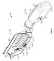
- FIG. 1is a perspective view of an infusion pump system in accordance with some embodiments, in accordance with some embodiments.
- FIG. 2is a perspective view of the infusion pump system of FIG. 1 in an assembled state.
- FIG. 3is another perspective view of the infusion pump system of FIG. 2 .
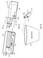
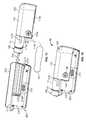
- FIG. 4is a perspective view of the infusion pump system of FIG. 1 in a detached state.
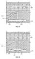
- FIG. 5is another perspective view of the infusion pump system on FIG. 4 .
- FIG. 6is a perspective view of an infusion pump system, in accordance with some embodiments.
- FIG. 7is a perspective view of the infusion pump system of FIG. 6 worn on clothing of a user.
- FIG. 8is a perspective view of an infusion pump system worn on skin of a user, in accordance with particular embodiments.
- FIG. 9is a perspective view on an infusion pump system having an illumination instrument, in accordance with some embodiments.
- FIG. 10is a perspective view of an infusion pump system having an illumination instrument, in accordance with particular embodiments.
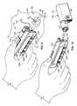
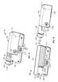
- FIGS. 11-12are perspective views of a pump device being detached from a controller device, in accordance with some embodiments.
- FIGS. 13-14are perspective views of the pump device of FIGS. 11-12 being discarded and the controller device of FIGS. 11-12 being reused with a new pump device.
- FIGS. 15-16are perspective views of the new pump device of FIG. 13 being attached to the controller device of FIG. 13 .
- FIG. 17is an exploded perspective view of a controller device for an infusion pump system, in accordance with some embodiments.
- FIG. 18is an exploded perspective view of a pump device for an infusion pump system, in accordance with some embodiments.
- FIG. 19is a perspective view of a portion of the pump device of FIG. 18 .
- FIG. 20is a top view of a portion of the pump device of FIG. 18 .
- FIG. 21is an exploded perspective view of a medicine cartridge and a flexible piston rod, in accordance with some embodiments.
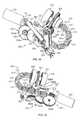
- FIGS. 22-25are perspective views of a portion of a drive system for the pump device of FIG. 18 .
- FIG. 26is a perspective view of occlusion sensor circuitry from a controller device arranged adjacent to a cap of a pump device, in accordance with some embodiments.
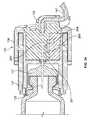
- FIG. 27is a cross-sectional view of the cap device of FIG. 26 .
- FIGS. 28-29are cross-sectional views of an occlusion sensor for use in an infusion pump system.
- FIGS. 30-31are cross-sectional views of the occlusion sensor of FIGS. 28-29 .
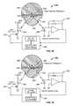
- FIGS. 32-33are diagrams of the occlusion sensor of FIGS. 30-31 .
- FIG. 34is a cross-sectional view of an alternative embodiment of the cap device of FIG. 26 .
- FIGS. 35-36are cross-sectional views of a portion of a fluid channel through the cap device of FIG. 34 , in accordance with some embodiments.
- FIGS. 37-38are diagrams of an alternative embodiment of an occlusion sensor to be arranged adjacent to the cap device of FIG. 34 .
- an infusion pump system 10can include a pump device 100 and a controller device 200 that communicates with the pump device 100 .
- the pump device 100includes a housing structure 110 that defines a cavity 116 in which a fluid cartridge 120 can be received.
- the pump device 100also includes a cap device 130 to retain the fluid cartridge 120 in the cavity 116 of the housing structure 110 .
- the pump device 100includes a drive system (described in more detail below) that advances a plunger 125 in the fluid cartridge 120 so as to dispense fluid therefrom.
- the controller device 200communicates with the pump device 100 to control the operation of the drive system.
- the usercan (in some embodiments) conveniently wear the infusion pump system 10 on the user's skin under clothing or in the user's pocket while receiving the fluid dispensed from the pump device 100 .
- the controller device 200may be configured as a reusable component that provides electronics and a user interface to control the operation of the pump device 100 .
- the pump device 100can be a disposable component that is disposed of after a single use.
- the pump device 100can be a “one time use” component that is thrown away after the fluid cartridge 120 therein is exhausted. Thereafter, the user can removably attach a new pump device 100 to the reusable controller device 200 for the dispensation of fluid from a new fluid cartridge 120 . Accordingly, the user is permitted to reuse the controller device 200 (which may include complex or valuable electronics) while disposing of the relatively low-cost pump device 100 after each use.
- Such a pump system 10can provide enhanced user safety as a new pump device 100 (and drive system therein) is employed with each new fluid cartridge 120 .
- the pump device 100is configured to removably attach to the controller device 200 in a manner that provides a secure fitting, an overall compact size, and a reliable electrical connection that is resistant to water migration.
- the controller device 200includes a housing 210 having a number of features that mate with complementary features of the pump housing 110 .
- the controller device 200can removably attach with the pump device 100 in a generally side-by-side configuration while not fully surrounding the pump housing 110 .
- the pump device 100 and the controller device 200can be separate components that fit together, but the overall size of the combined assembly is reduced because there is no requirement for one component (e.g., the controller device) to completely surround or envelop the second component (e.g., the pump device).
- the compact sizepermits the infusion pump system 10 to be discrete and portable (as described below in connection with FIGS. 6-8 ).
- at least one of the pump device 100 or the controller device 200may include a release member that facilitates an easy-to-use detachment and replacement process.
- an exhausted pump device 100may be a “one time use” component that is discarded after being used, and a new pump device 100 ′ (having a new medicine cartridge 120 ′) can thereafter be attached to the controller device 200 .
- the pump device 100 and the controller device 200can be mounted to one another so that the assembled system 10 is resistant to migration of external contaminants (e.g., water from precipitation or splashing, sweat, and the like) both into the pump housing structure 110 and the controller housing structure 210 .
- the infusion pump system 10may include one or more seals that are arranged to hinder migration of external contaminants into the cavity of the pump device 100 (e.g., to protect the insulin container 120 and the drive system during operation).
- the infusion pump systemmay include one or more gaskets arranged proximate to the electrical connection location (between the pump device 100 and the controller device 200 ) to protect the electrical connection from migration of external contaminants.
- the infusion pump system 10can be assembled into a water resistant configuration that protects sensitive components from water migration (e.g., if the user encounters water while wearing the pump system 10 ).
- the controller device 200can be equipped with an illumination instrument 230 that provides the user with an opportunity to illuminate and inspect a targeted location.
- an illumination instrument 230that provides the user with an opportunity to illuminate and inspect a targeted location.
- the light emitting device 230can be directed at the infusion site on the user's skin to verify that the infusion set is properly embedded, or the light emitting device 230 can be directed at the pump device 100 to illuminate the cavity 116 or other areas.
- the controller device 200can include a sensor configuration that detects occlusions in the fluid flow path extending to the user.
- the controller device 200may include an optical sensor system 250 that detects the amount of light reflected from a portion of the cap device 130 .
- the amount of light reflected from the cap device 130may change if an occlusion occurs to cause an increase in the fluid pressure.
- some embodiments of the optical sensor system 250may operate using the principle of total internal reflection.
- the optical sensor system 250may include a number of components that are housed in the controller device 200 .
- the light emitter and light sensormay be arranged on a sensor circuit in the controller device 200 , thereby permitting these components to be reused along with the controller device (while the relatively low cost components in the pump device 100 are discarded after the “one time use” of the pump device 100 ).
- the pump system 10is a medical infusion pump system that is configured to controllably dispense a medicine from the cartridge 120 .
- the fluid cartridge 120may contain a medicine 126 ( FIG. 1 ) to be infused into the tissue or vasculature of a targeted individual, such as a human or animal patient.
- the pump device 100can be adapted to receive a medicine cartridge 120 in the form of a carpule that is preloaded with insulin or another medicine for use in the treatment of Diabetes (e.g., Byetta®, Symlin®, or others).
- a medicine cartridge 120may be supplied, for example, by Eli Lilly and Co. of Indianapolis, Ind.
- the fluid cartridge 120may have other configurations.
- the fluid cartridgemay comprise a reservoir that is integral with the pump housing structure 110 (e.g., the fluid cartridge can be defined by one or more walls of the pump housing structure 110 that surround a plunger to define a reservoir in which the medicine is injected or otherwise received).
- the pump device 100may include one or more structures that interfere with the removal of the medicine cartridge 120 after the medicine cartridge 120 is inserted into the cavity 116 .
- the pump housing structure 110may include one or more retainer wings 119 that at least partially extend into the cavity 116 to engage a portion of the medicine cartridge 120 when the medicine cartridge 120 is installed therein.
- the pump housing structure 110includes a pair of opposing retainer wings 119 (only one is shown in the view in FIG. 1 ) that flex toward the inner surface of the cavity 116 during insertion of the medicine cartridge 120 .
- the retainer wings 119are biased to flex outward (toward the center of the cavity 116 ) so that the retainer wings 119 engage a neck portion 129 of the medicine cartridge 120 .
- This engagement with the retainer wings 119 and the neck portion 129hinder any attempts to remove the medicine cartridge 120 away from the pump device 100 .
- Such a configurationmay facilitate the “one-time-use” feature of the pump device 100 .
- the pump device 100Because the retainer wings 119 interfere with attempts to remove the medicine cartridge 120 from the pump device 100 , the pump device 100 will be discarded along with the medicine cartridge 120 after the medicine cartridge 120 is emptied, expired, or otherwise exhausted.
- the retainer wings 119may serve to hinder attempts to remove the exhausted medicine cartridge 120 and to insert a new medicine cartridge 120 into the previously used pump device 100 .
- the pump device 100may operate in a tamper-resistant and safe manner because the pump device 100 can be designed with predetermined life expectancy (e.g., the “one-time-use” feature in which the pump device is discarded after the medicine cartridge 120 is emptied, expired, or otherwise exhausted).
- the cap device 130can be joined with the pump device 100 after the medicine cartridge is inserted in the cavity 116 .
- the cap device 130is multifunctional in that it performs a number of functions for the pump device operation.
- attachment of the cap device 130may cause one or more of the following preparatory functions: forcing the plunger 125 ( FIG. 1 ) of the fluid cartridge 120 to engage with the piston rod (not shown in FIGS. 1-3 , refer for example to FIG. 19 ), piercing a septum 121 of the fluid cartridge 120 to provide a flow path for the fluid (refer for example to FIG.
- attachment of the cap device 130may also cause one or more of the following safety related functions: aligning an occlusion sensor 250 with the a portion of the fluid flow path (described in connection with FIGS. 26-38 ), sealing the pump housing 110 (e.g., using a polymeric o-ring seal 131 or the like) to resist migration of external contaminants into the cavity 116 , and ceasing or preventing the dispensation of fluid if the cap device 130 is improperly engaged with the pump housing 110 .
- the cap device 130may supplement or replace the previously described retainer wings 119 by locking into position after joining with the pump housing 110 , thereby hindering removal of the fluid cartridge 120 in the pump housing 110 .
- the cap device 130can include one or more alignment tabs 132 that operate to ensure that the cap device 130 is joined with the pump housing 110 in a selected orientation.
- the cap device 130may include an output port 139 that connects with tubing (e.g., FIG. 6 ) for dispensation of the medicine to the user.
- the output port 139may have an angled orientation such that a portion of the tubing extends transversely to the central axis of the cartridge 120 and cap device 130 .
- the alignment tabs 132 arranged on the body of the cap device 130can align with adjacent surfaces of the controller housing 210 to provide the selected orientation of the output port during operation.
- the alignment tabs 132would receive interference from the barrel channel 211 of the controller housing 210 . As such, the user would be unable to attach the pump device 100 to the controller 200 , thereby indicating to the user that the cap device 130 must be reoriented to the selected position.
- the controller device 200may be removably attached to the pump device 100 so that the two components are mechanically mounted to one another in a fixed relationship. Such a mechanical mounting can form an electrical connection between the removable controller device 200 and the pump device 100 .
- the controller device 200may be in electrical communication with a portion of a drive system (not shown in FIGS. 1-3 ) of the pump device 100 .
- the pump device 100includes a drive system that causes controlled dispensation of the medicine or other fluid from the cartridge 120 .
- the drive systemincrementally advances a piston rod (not shown in FIGS. 1-3 ) longitudinally into the cartridge 120 so that the fluid is forced out of an output end 122 .
- a septum 121 ( FIG. 1 ) at the output end 122 of the fluid cartridge 120can be pierced to permit fluid outflow when the cap device 130 is connected to the pump housing structure 110 (described in more detail below).
- the controller device 200communicates electronic control signals via a hardwire-connection (e.g., electrical contacts or the like) to the drive system or other components of the pump device 100 .
- the drive system of the pump device 100causes medicine to incrementally dispense from the medicine cartridge 120 .
- the controller deviceis configured to removably attach to the pump device 100 in a side-by-side arrangement.
- the controller device 200can be electrically connected with the pump device 100 while the controller device 200 remains outside of the pump housing 110 (and, likewise, the pump device 100 remains outside of the controller housing 210 ).
- the pump device 100 and the controller device 200can be separate components that fit together, but the overall size of the combined assembly is reduced because there is no requirement for one component (e.g., the controller device) to completely surround or envelop the second component (e.g., the pump device).
- the compact sizepermits the infusion pump system 10 to be discrete and portable when the pump device 100 is attached with the controller device 200 (as shown in FIGS. 2-3 ).
- the controller device 200includes a controller housing structure 210 having a number of features (e.g., a barrel channel 211 , a rail 212 , a depression 213 , and a guide channel 214 a - b that is segmented by a release latch 215 ) that are configured to mate with complementary features (e.g., a barrel 111 , a slider channel 112 , an mating extension 113 , and a segmented guide rail 114 a - b ) of the pump housing structure 110 so as to form a releasable mechanical connection (as shown, for example, in FIGS. 1 and 4-5 ).
- a controller housing structure 210having a number of features (e.g., a barrel channel 211 , a rail 212 , a depression 213 , and a guide channel 214 a - b that is segmented by a release latch 215 ) that are configured to mate with complementary features (e.g., a
- Such mating features of the pump housing structure 110 and the controller housing structure 210can provide a secure connection in the previously described side-by-side arrangement. It should be understood that, in other embodiments, other features or connector devices can be used to facilitate the side-by-side mounting arrangement. These other features or connector devices may include, for example, magnetic attachment devices, mating tongues and grooves, or the like.
- the pump device 100may include an electrical connector 118 (e.g., having conductive pads, pins, and the like) that are exposed to the controller device 200 and that mate with a complementary electrical connector (refer to connector 218 in FIG. 4 ) on the adjacent face of the controller device 200 .
- the electrical connectors 118 and 218provide the electrical communication between the control circuitry (refer, for example, to FIG. 17 ) housed in the controller device 200 and at least a portion of the drive system or other components of the pump device 100 .
- the electrical connectors 118 and 218permit the transmission of electrical control signals to the pump device 100 and the reception of feedback signals (e.g., sensor signals) from particular components within the pump device 100 .
- the infusion pump system 10may include a gasket 140 that provides a seal that is resistant to migration of external contaminants when the pump device 100 is attached to the controller device 200 .
- the infusion pump system 10can be assembled into a water resistant configuration that protects the electrical interconnection from water migration (e.g., if the user encounters water while carrying the pump system 10 ).
- the controller device 200includes a user interface 220 that permits a user to monitor the operation of the pump device 100 .
- the user interface 220includes a display 222 and one or more user-selectable buttons (e.g., four buttons 224 a , 224 b , 224 c , and 224 d in this embodiment).
- the display 222may include an active area in which numerals, text, symbols, images, or a combination thereof can be displayed (refer, for example, to FIG. 2 ).
- the display 222may be used to communicate a number of settings or menu options for the infusion pump system 10 .
- the usermay press one or more of the buttons 224 a , 224 b , 224 c , and 224 d to shuffle through a number of menus or program screens that show particular settings and data (e.g., review data that shows the medicine dispensing rate, the total amount of medicine dispensed in a given time period, the amount of medicine scheduled to be dispensed at a particular time or date, the approximate amount of medicine remaining in the cartridge 120 , or the like).
- the usercan adjust the settings or otherwise program the controller device 200 by pressing one or more buttons 224 a , 224 b , 224 c , and 224 d of the user interface 220 .
- the usermay press one or more of the buttons 224 a , 224 b , 224 c , and 224 d to change the dispensation rate of insulin or to request that a bolus of insulin be dispensed immediately or at a scheduled, later time.
- the usercan activate the illumination instrument 230 on the controller device 200 by pressing one or more buttons 224 a , 224 b , 224 c , and 224 d of the user interface 220 .
- the display 222 of the user interface 220may be configured to display quick reference information when no buttons 224 a , 224 b , 224 c , and 224 d have been pressed.
- the active area of the display 222can display the time and the date for a period of time after no button 224 a , 224 b , 224 c , and 224 d has been actuated (e.g., five seconds, 10 seconds, 30 seconds, 1 minute, 5 minutes, or the like). Thereafter, the display 222 may enter sleep mode in which the active area is blank, thereby conserving battery power.
- the active areacan display particular device settings, such as the current dispensation rate or the total medicine dispensed, for a period of time after no button 224 a , 224 b , 224 c , or 224 d has been actuated (e.g., five seconds, 10 seconds, 30 seconds, 1 minute, 5 minutes, or the like). Again, thereafter the display 222 may enter sleep mode to conserve battery power.
- particular device settingssuch as the current dispensation rate or the total medicine dispensed
- the display 222can dim after a first period of time in which no button 224 a , 224 b , 224 c , or 224 d has been actuated (e.g., after 15 seconds or the like), and then the display 22 can enter sleep mode and become blank after a second period of time in which no button 224 a , 224 b , 224 c , or 224 d has been actuated (e.g., after 30 seconds or the like).
- the dimming of the display device 222can alert a user viewing the display device 222 when the active area 223 of the display device will soon become blank.
- the controller device 200when the controller device 200 is connected to the pump device 100 , the user is provided with the opportunity to readily monitor infusion pump operation by simply viewing the user interface 220 of the controller device 200 connected to the pump device 100 .
- Such monitoring capabilitiesmay provide comfort to a user who may have urgent questions about the current operation of the pump device 100 (e.g., the user may be unable to receive immediate answers if wearing an infusion pump device having no user interface attached thereto).
- the usermay carry and operate a separate module to monitor the operation of the infusion pump device 100 , thereby simplifying the monitoring process and reducing the number of devices that must be carried by the user.
- the usercan readily operate the user interface 220 of the controller device 200 , which is removably attached to the pump device 100 , without the requirement of locating and operating a separate monitoring module.
- the user interface 200is not limited to the display and buttons depicted in FIGS. 1-3 .
- the user interface 220may include only one button or may include a greater numbers of buttons, such as two buttons three buttons, four buttons, five buttons, or more.
- the user interface 220 of the controller device 200may include a touch screen so that a user may select buttons defined by the active area of the touch screen display.
- the user interface 220may comprise audio inputs or outputs so that a user can monitor the operation of the pump device 100 .
- the controller device 200is removably attached to the pump device 100 in a side-by-side arrangement.
- the pump device 100may be moved in a longitudinal direction (e.g., refer to direction 219 in FIG. 15 ) toward the controller device 200 until the complementary features connect and secure the separate components in the side-by-side arrangement.
- the pump device 100 and the controller device 200can be separate components that fit together, but the overall size of the combined assembly is reduced because there is no requirement for one component (e.g., the controller device or pump device) to surround or envelop the second component (e.g., the pump device or controller device).
- the pump device 100 and controller device 200can be readily attached together with a “one-movement” process that is convenient to the user (described in more detail below).
- the controller device 200includes a controller housing structure 210 having a number of features that are configured to mate with complementary features of the pump housing structure 110 so as to form a releasable mechanical connection.
- the pump housing structure 110may include a barrel 111 that mates with a complementary barrel channel 211 of the controller housing 210 .
- the pump housing 110includes slider channel 112 that slidably engages a complementary rail 212 defined by the controller housing 210 . The slider channel 112 can guide the relative motion between the pump device 100 and the controller device 200 in the longitudinal direction during the attachment process.
- the pump housing 110may include a segmented rail 114 a - b ( FIG.
- the pump housing 110may include an extension 113 ( FIG. 1 ) that mates with a depression 213 ( FIG. 5 ) in the controller housing 210 when the pump device 100 is fully attached to the controller device 200 .
- the electrical connector 118( FIG. 5 ) of the pump device 100 is directed toward engagement with the mating connector 218 ( FIG. 4 ) of the controller device 200 .
- the release member 215is shifted to a position between the segmented rails 114 a - b so as to prevent withdrawal of the connection.
- the extension 113 and barrel 111are mated with the corresponding depression 213 and barrel channel 211 so as to resist relative rotational movement between the pump device 100 and the controller device 200 .
- the physical attachment of the electrical connectors 118 and 218may also serve to resist relative rotational movement between the pump device 100 and the controller device 200 .
- the slide channel 112is mated with the corresponding rail 112 and barrel channel 211 so as to resist relative side-to-side movement between the pump device 100 and the controller device 200 .
- the pump device 100is configured to removably attach to the controller device 200 in a manner that provides a secure fitting, an overall compact size, and a reliable electrical connection.
- the controller device 200can be electrically connected with the pump device 100 while the controller device 200 remains outside of the pump housing 110 (and, likewise, the pump device 100 remains outside of the controller housing 210 ).
- the overall size of the assembled system 10can be minimized, thereby providing an infusion pump system 10 having a discrete size and enhanced portability.
- the attachment of the pump device 100 to the controller device 200can be accomplished by a user with a convenient “one-movement” process.
- the usercan readily slide the pump device 100 and the controller device 200 toward one another in a single movement (e.g., in the longitudinal direction) that causes both a physical connection and an electrical connection.
- the release member 215may be arranged so as to automatically adjust to a locked position when the pump device 100 is advanced into engagement with the controller device 200 .
- the infusion pump system 10permits users to readily join the pump device 100 and the controller device 200 without compound or otherwise difficult hand movements—a feature that can be beneficial to child users or to elderly users.
- the pump device 100 and the controller device 200can be attached in a manner that is resistant to migration of external contaminants (e.g., water, dirt, and the like) both into the pump housing structure 110 and the controller housing structure 210 .
- external contaminantse.g., water, dirt, and the like
- the electrical connector 118 ( FIG. 5 ) of the pump device 100is directed toward engagement with the mating connector 218 ( FIG. 4 ) of the controller device 200 .
- the gasket 140is compressed between the adjacent surfaces of the pump housing 110 and the controller housing 210 .
- the gasket 140thereby forms a water-resistant seal between the ambient environment and the mated connectors 118 and 218 .
- the gasket 140may comprise a polymer foam material that is adhered to a surface of either the pump housing 110 or the controller housing 210 (e.g., adhered to the pump housing 110 in this embodiment).
- the gasket 140may be die cut to a selected shape so as to include an aperture for the electrical connection.
- the gasket 140surrounds the electrical connection when the pump device 100 is secured to the controller device 200 .
- the configurationprovides protection from water migration to one or both of the electrical connectors 118 and 218 . Accordingly, in particular circumstances, the infusion pump system 10 can be assembled into a “water tight” configuration that protects sensitive internal components from water migration in the event that the user encounters water while wearing the pump system 10 .
- the gasket 140may resist migration of water to the electrical connectors 118 and 218 even when the system 10 is submerged underwater (e.g., in a pool, in a bath, or the like) for an extended period of time, such as at least 10 minutes, at least 30 minutes, at least one hour, at least two hours, and preferably at least four hours.
- the gasket 140is arranged to extend generally perpendicular to the assembly motion when the pump device 100 is being attached to the controller device.
- the pump device 100can be attached to the controller device 200 by moving the pump device 100 in the longitudinal direction (e.g., refer to direction 219 in FIG. 15 ).
- the gasket 140includes a major interface surface extends in a generally lateral direction that is perpendicular to the longitudinal assembly motion.
- the gasket 140extends in a direction (e.g., the lateral direction in this embodiments) that is generally perpendicular to the attachment direction (the longitudinal direction in this embodiment), the gasket 140 can be sufficiently compressed to form a seal when the user performs the “one-movement” process to attach the pump device 100 and the controller device 200 .
- the infusion pump system 10may include one or more seals that are arranged to hinder migration of external contaminants between the cap device 130 and the pump housing 110 into the cavity 116 of the pump device 100 .
- the seal 131 arranged between the cap device 130 and the barrel 111can provide an effective water-resistant seal against water migration into the cavity.
- the medicine cartridge 120 and pump drive system(not shown in FIGS. 4-5 ) can be protected during operation.
- some embodiments of the infusion pump system 10may employ a power source arranged in pump device 100 or the controller device 200 that draws upon surrounding air for optimum operation. Because the controller device 200 and the pump device 100 may be sealed to resist water migration during normal usage, a water-resistant vent instrument 145 may be used to provide the air to the power source without permitting migration of water therethrough.
- the pump device 100may house a power source 345 in the form of a zinc-air cell battery (refer to FIG. 18 ), which draws upon the surrounding air during operation.
- the pump housing 110is preferably sealed to protect the internal drive system and medicine cartridge from water migration.
- the pump housing 110may include a water-resistant vent instrument 145 disposed proximate to the zinc-air cell battery 345 so that some air may pass through the vent 145 and toward the battery.
- the water-resistant vent instrument 145may include one or more layers of a material that is permeable to air and resistant to passage of liquids such as water.
- the water-resistant vent instrument 145may include one or more layers of a GORE-TEX material to resist the migration of water into the pump device while permitting the passage of air toward the battery.
- the pump device 100 and the controller device 200can be mounted to one another so that the assembled system 10 is resistant to water migration both into the pump housing structure 110 and the controller housing structure 210 .
- Such a configurationmay also provide water-resistant protection for the electrical connection between the pump device 100 and the controller 200 .
- the sensitive internal components in the controller device 200 and the pump device 100can be reliably protected from water migration if the user encounters water (e.g., rain, incidental splashing, and the like) while using the pump system 10 .
- the infusion pump system 10may be configured to be portable and can be wearable and concealable.
- a usercan conveniently wear the infusion pump system 10 on the user's skin (e.g., skin adhesive) underneath the user's clothing or carry the pump device 100 in the user's pocket (or other portable location) while receiving the medicine dispensed from the pump device 100 .
- the drive system of the pump device 100may be arranged in a compact manner so that the pump device 100 has a reduced length.
- the overall length of the pump housing structure 110(which contains medicine cartridge and the drive system) can be about 7 cm to about 10 cm and about 7 cm to about 9 cm (about 8.3 cm or less in one embodiment).
- the pump housing structure 110may have an overall height of about 2 cm to about 4 cm (about 3.1 cm or less in one embodiment) and an overall thickness of about 8 mm to about 20 mm (about 17.5 mm or less in one embodiment).
- the controller device 200can be figured to mate with the pump housing 110 so that, when removably attached to one another, the components define a portable infusion pump system that stores a relatively large quantity of medicine compared to the overall size of the unit.
- the infusion pump system 10(including the removable controller device 200 attached to the pump device 100 having the cap 130 ) may have an overall length of about 7 cm to about 10 cm (about 9.3 cm or less in one embodiment), an overall height of about 2 cm to about 5 cm (about 4.2 cm or less in one embodiment), and an overall thickness of about 8 mm to about 20 mm (about 17.5 mm or less in one embodiment).
- the pump system 10is shown in FIG. 6 as being held in a user's hand 5 so as to illustrate an exemplary size of the system 10 in accordance with some embodiments.
- This embodiment of the infusion pump system 10is compact so that the user can wear the portable infusion pump system 10 (e.g., in the user's pocket, connected to a belt clip, adhered to the user's skin, or the like) without the need for carrying and operating a separate module.
- the cap device 130 of the pump device 100may be configured to mate with an infusion set 146 .
- the infusion set 146is tubing system that connects the infusion pump system 10 to the tissue or vasculature of the user (e.g., to deliver medicine into the tissue or vasculature under the user's skin)
- the infusion set 146may include a flexible tube 147 that extends from the pump device 100 to a subcutaneous cannula 149 retained by a skin adhesive patch 148 that secures the subcutaneous cannula 149 to the infusion site.
- the skin adhesive patch 148can retain the infusion cannula 149 in fluid communication with the tissue or vasculature of the patient so that the medicine dispensed through the tube 147 passes through the cannula 149 and into the user's body.
- the cap device 130may provide fluid communication between the output end 122 ( FIG. 1 ) of the medicine cartridge 120 and the tube 147 of the infusion set 146 .
- the tube 147may be directly connected to the output port 139 ( FIG. 1 ) of the cap device 130 .
- the infusion set 146may include a connector (e.g., a Leur connector or the like) attached to the tube 147 , and the connector can then mate with the cap device 130 to provide the fluid communication to the tube 147 .
- the usercan carry the portable infusion pump system 10 (e.g., in the user's pocket, connected to a belt clip, adhered to the user's skin, or the like) while the tube 147 extends to the location in which the skin is penetrated for infusion.
- the userdesires to monitor the operation of the pump device 100 or to adjust the settings of the infusion pump system 10 , the user can readily access the user interface 220 of the controller device 200 without the need for carrying and operating a separate module (refer for example to FIG. 6 ).
- the infusion pump system 10is pocket-sized so that the pump device 100 and controller device 200 can be worn in the user's pocket 6 or in another portion of the user's clothing.
- the pump device 100 and the controller device 200can be attached together and form the system that comfortably fits into a user's pocket 6 .
- the usercan carry the portable infusion pump system 10 and use the tube 147 of the infusion set 146 extends to direct the dispensed medicine to the desired infusion site.
- the usermay desire to wear the pump system 10 in a more discrete manner. Accordingly, the user may pass the tube 147 from the pocket 6 , under the user's clothing, and to the infusion site where the adhesive patch 148 is positioned.
- the pump system 10can be used to delivery medicine to the tissues or vasculature of the user in a portable, concealable, and discrete manner.
- the infusion pump system 10may be configured to adhere to the user's skin 7 directly at the location in which the skin is penetrated for medicine infusion.
- a rear surface 102 ( FIG. 3 ) of the pump device 100may include a skin adhesive patch so that the pump device 100 is physically adhered to the skin of the user at a particular location.
- the cap device 130may have a configuration in which medicine passes directly from the cap device 130 into an infusion cannula 149 that is penetrated into the user's skin.
- the fluid output port 139 through the cap device 130can include a curve or a 90° corner so that the medicine flow path extends longitudinally out of the medicine cartridge and thereafter laterally toward the patient's skin 7 .
- the usercan readily access the user interface 220 of the controller device 200 without the need for carrying and operating a second, separate device.
- the usermay look toward the pump device 100 to view the user interface 220 of the controller device 200 that is removably attached thereto.
- the usercan temporarily detach the controller device 200 (while the pump device 100 remains adhered to the skin 7 ) so as to view and interact with the user interface 220 .
- the infusion pump system 10can include an illumination instrument 230 that provides the user with an opportunity to illuminate and inspect a targeted location.
- the illumination instrument 230can be useful in situations where the ambient lighting is insufficient for the user's inspection needs (e.g., during the night, during presentation or movie in which the lighting is low, or the like).
- the illumination instrument 230can be arranged on the pump device 100 , the controller device 200 , or both. In this embodiment, the illumination instrument is arranged on the controller device 200 .
- the illumination instrument 230can be directed at the infusion site on the user's skin 8 to verify that the infusion set cannula 149 is properly embedded (refer, for example, to FIG. 9 ).
- the illumination instrument 230can be directed at the pump device 100 to illuminate some portion of the pump device 100 , such as the cavity 116 in which the medicine cartridge 120 is received (refer to FIG. 10 ).
- the usermay be instructed to periodically assess the condition of the connection of the infusion set 146 into the user's body.
- This assessmentcan include visually inspecting the adhesive pad 148 that secures the set to the body and the cannula 149 that passes through the skin 8 to provide access for the medicine to enter the tissue or vasculature. In some cases, this inspection reveals that a new infusion set 146 is needed, and the user can thereafter change the infusion set 146 by attaching a new infusion set 146 to the user's skin 8 and the to the pump device 100 .
- Changing the infusion set 146can be a detailed process that requires the user to visualize the infusion site along the skin 8 as well as the tip of the infusion cannula 149 prior to insertion (e.g., to verify proper priming or filling of the infusion set tubing 147 ).
- the usermay encounter a need to visually inspect one or more or components of the pump device 100 .
- the usermay visually inspect the medicine cartridge 120 in the cavity 116 of the pump housing 110 to verify the fluid level in the medicine cartridge 120 .
- the controller device 200can include sensors and software to track medicine usage and provide an estimate of the remaining fluid volume, visual confirmation of the fluid level can be comforting to many users. If the visual inspection of the cavity 116 reveals that the medicine cartridge 120 has a low fluid level or is broken, the user can employ a new pump device 100 ′ and a new medicine cartridge 120 ′ as described below in connection with FIGS. 11-16 .
- the infusion pump system 10can be equipped with the illumination instrument 230 to conveniently aid in visual inspection processes.
- visual inspection and possible change of the infusion set 146may be required in less than optimal conditions, including low-light conditions.
- visual inspection of the pump housing cavity 116 (and the medicine cartridge 120 therein)may be required in low-light conditions.
- the user interface 220 of the controller device 200can include an illuminated display screen 222 to facilitate the user's view of the display screen 22 , but the illumination instrument 230 provides a dedicated light source for illuminating targeted sites external to the controller device 200 (e.g., the skin 8 , the infusion set 146 , or the like).
- the illumination instrument 230can include one or more user triggered light sources that are positioned to direct illumination at targeted objects outside of the pump system 10 or at components of the pump device 100 .
- the light sourceis arranged on the controller device 200 .
- Such an arrangementprovides close proximity to the control circuitry 240 housed in the controller device 200 .
- the illumination instrument 230may include a light source in the form of an LED device 232 ( FIG. 17 ) that is electrically connected to the control circuitry 240 ( FIG. 17 ) in the controller housing 210 .
- the light transmitted from the LED device 232may be directed through a light guide 234 ( FIGS. 17 and 26 ) extending to the controller housing 210 so that the light exits the light guide 234 and illuminates the targeted object.
- the light guide 234may operate as a light transmissive cover that permits light to pass out of the controller device 200 while sealing out water or other contaminants.
- Such a constructionmay provide an illumination instrument 230 that emits an inspection light even when submerged underwater for a particular period of time.
- the light from the illumination instrument 230can be emitted from a side of the controller device 200 that is different from the side on which the user interface 220 is exposed.
- the light from the illumination instrument 230exits from the light guide 234 toward a targeted site while the display 222 and buttons 224 a - d face a different direction.
- the illumination instrument 230can direct an inspection light toward a targeted site while the user interface 220 remains in a viewable position for the user.
- the illumination instrument 230emits a beam of light (e.g., a generally cylindrical or conical beam) that provides an intensity sufficient for visually inspecting external sites.
- a beam of lighte.g., a generally cylindrical or conical beam
- the light transmitted from the LED device 232may be directed through a plastic light guide 234 to provide a beam of light having an illumination intensity that is sufficient to noticeably illuminate a specific area (e.g., a circular area having a diameter of about 10 inches) around a targeted site from more than six inches away, from more that twelve inches away, and preferably from more than eighteen inches away.
- the usermay, for example, actuate one or more buttons 224 a - d of the user interface 220 to activate the illumination instrument 230 .
- the illumination instrument 230may be configured to activate and transmit light when the user presses a single button (e.g., activate immediately when the single button is pressed or after the single button is pressed-and-held for a short period of time such as two seconds). The illumination device 230 may remain activated while the selected button was held down, and would thereafter shut off when the button is no longer pressed. This press-and-hold activation sequence can conserve battery power as the light is emitted only as long as the user holds the button.
- the illumination instrument 230may be configured to activate and transmit light when the user presses a specified button sequence. The light would be emitted from the illumination instrument 230 while the user would have both hands available for the inspection process. To deactivate the illumination instrument 230 in this embodiment, the user may press another button sequence.
- the illumination instrument 230can operate in conjunction with a timer that automatically deactivates the light source after a predetermined period of time.
- the duration of the timercould either be preset at the factory or adjustable by the user (e.g., by selecting the particular menu settings with the user interface 220 ).
- the control circuitry 240FIG. 17 ) may operate to automatically shut off the illumination instrument 230 after a predetermined period of time, such as 5 seconds, 10 seconds, 20 seconds, 30 seconds, or the like.
- a timer featurecan reduce the required user input effort and can conserve battery power.
- the illumination instrument 230may serve as an indicator to the user that a particular condition exists.
- the illumination instrument 230may be automatically activated by the controller device 200 to serve as an alarm that an error has occurred (e.g., a controller error, a drive system error, a flow path error, or the like).
- the illumination instrument 230may emit light in a steady state or in a pulsing state to notify the user of the detected error.
- the illumination instrument 230may be automatically activated by the controller device during particular user interface activities. For example, when the user indicates that a new infusion set 146 is attached and should be “primed” to remove air gaps in the tubing 147 , the controller device 200 can automatically activate the illumination instrument 230 . Such automatic activation may be useful for the user in that the illumination device 230 can be readily directed to inspect the infusion set 146 without having to press a separate sequence of buttons to activate the light source.
- the controller devicemay include features that limit when the illumination instrument can be activated.
- the controller device 200may include an ambient light sensor 226 ( FIGS. 9-10 ) to detect the light level available to the user. If the ambient light level is higher than a particular threshold (e.g., if the user is located in a lighted room or in daylight conditions), the illumination instrument 230 would not be automatically activated as previously described. As such, the battery power can be conserved by reducing the unnecessary illumination effects.
- the ambient light sensor 226may be used by the controller device 200 to conserve battery power in other ways. For example, the lighting for display device 222 of the user interface 220 can be automatically adjusted based on the lighting condition detected by the ambient light sensor 226 .
- the backlight for the display device 222may be automatically reduced by the controller device 200 if the user is located in high-level lighting conditions (e.g., in a lighted room or in daylight conditions). Also, the backlight for the display device 222 may be automatically increased by the controller device 200 if the user is located in low-level lighting conditions.
- high-level lighting conditionse.g., in a lighted room or in daylight conditions.
- the backlight for the display device 222may be automatically increased by the controller device 200 if the user is located in low-level lighting conditions.
- the activation of the illumination instrument 230may be limited by the controller device 200 for reasons other than ambient lighting conditions.
- the illumination instrument 230may be limited if the controller device 200 detects that the remaining capacity of the power source reaches below a threshold level. In such circumstances, the battery power can be automatically reserved for use in operating the drive system to deliver medicine to the user.
- the illumination instrument 230may be limited by the controller device 200 based on a power use profile.
- the power use profilecan provide an estimate of remaining battery life based on the user's activity with the infusion pump system 10 (e.g., activations of the drive system to provide basal and bolus dispensations, historical interaction with the user interface 220 , history of activating the illumination tool, and the like).
- the controller device 200can estimate how long the remaining battery power will last in order to dispense the medicine remaining in the cartridge 120 . If the power use profile indicates that the remaining battery power may be insufficient, particular features such as the illumination tool 230 may be limited or shut off in order to conserve the remaining battery power for activating drive system and indicating alarms. In another example, the controller device 200 may limit the number of uses of the illumination instrument 230 to a preset number of activations per day or per attachment of a new pump device 100 . Again, providing a limit on the number of activations can conserve the battery power for other operations such as alarm indications and the drive system.
- the infusion pump system 10can be operated such that the pump device 100 is a disposable, non-reusable component while the controller device 200 is a reusable component.
- the pump device 100may be configured as a “one-time-use” device that is discarded after the medicine cartridge is emptied, expired, or otherwise exhausted.
- the pump device 100may be designed to have an expected operational life of about 1 day to about 30 days, about 1 day to about 20 days, about 1 to about 14 days, or about 1 day to about 7 days—depending on the volume of medicine in the cartridge 120 , the dispensation patterns that are selected for the individual user, and other factors.
- the medicine cartridge 120 containing insulinmay have an expected usage life about 7 days after the cartridge is removed from a refrigerated state and the septum 121 is punctured.
- the dispensation pattern selected by the usercan cause the insulin to be emptied from the medicine cartridge 120 before the 7-day period. If the insulin is not emptied from the medicine cartridge 120 after the 7-day period, the remaining insulin may become expired sometime thereafter. In either case, the pump device 100 and the medicine cartridge 120 therein can be discarded after exhaustion of the medicine cartridge 120 (e.g., after being emptied, expired, or otherwise not available for use).
- the controller device 200may be reused with subsequent new pump devices 100 ′ and new medicine cartridges 120 ′.
- the control circuitry, the user interface components, and other components that may have relatively higher manufacturing costscan be reused over a longer period of time.
- the controller device 200may be designed to have an expected operational life of about 1 year to about 7 years, about 2 years to about 6 years, or about 3 years to about 5 years—depending on a number of factors including the usage conditions for the individual user. Accordingly, the user is permitted to reuse the controller device 200 (which may include complex or valuable electronics) while disposing of the relatively low-cost pump device 100 after each use.
- Such a pump system 10can provide enhanced user safety as a new pump device 100 ′ (and drive system therein) is employed with each new fluid cartridge 120 .
- the pump device 100can be readily removed from the controller device 200 when the medicine cartridge 120 is exhausted.
- the medicine cartridge 120is inserted into the cavity 116 ( FIG. 1 ) of the pump housing 110 where it is retained by the cap device 130 .
- a portion of the pump housing 110can comprise a transparent or translucent material so that at least a portion of the medicine cartridge 120 is viewable therethrough.
- the usermay want to visually inspect the medicine cartridge when the plunger 125 is approaching the output end 122 of the medicine cartridge, thereby providing a visual indication that the medicine cartridge may be emptied in the near future.
- the barrel 111 of the pump housing 110comprises a generally transparent polymer material so that the user can view the medicine cartridge 120 to determine if the plunger 125 is nearing the end of its travel length.
- some embodiments of the pump device 100may include a label 117 a that is adhered around the barrel 111 .
- the label 117 amay provide a convenient location for basic user instructions, product identification information, and other information related to the infusion pump system 10 .
- the label 117 amay include a window 117 b through which the user may visually inspect if the plunger 125 is nearing the end of its travel length.
- the pump device 100has been used to a point at which the medicine cartridge 120 is exhausted.
- the plunger 125has been advanced, toward the left in FIG. 11 , over a period of time so that all or most of the medicine has been dispensed from the cartridge 120 .
- the controller device 200may provide a visual or audible alert when this occurs so as to remind the user that a new medicine cartridge is needed.
- the usermay visually inspect the medicine cartridge 120 through the barrel 111 of the pump housing 110 (and through the window 117 b of the label 117 a in this embodiment) to determine if the medicine cartridge 120 is almost empty.
- the pump device 100can be readily separated from the controller device 200 by actuating the release member 215 .
- the release member 215is a latch on the controller device 200 that is biased toward a locking position to engage the pump device 100 .
- the latchmay be arranged to engage one or more features on a lateral side of the pump housing 110 .
- the usermay actuate the release member 215 by moving the release member 215 in a lateral direction 216 ( FIG. 11 ) away from the pump device 100 (e.g., by applying a force with the user's finger).
- the segmented guide rail 114 a - bis free to slide longitudinally in the guide channel 214 a - b without interference from the release member 215 . Accordingly, the user can move the pump device 100 in a longitudinal direction 217 away from the controller device 200 .
- the segmented guide rail 114 a - bmay slide along the guide channel 214 a - b , the extension 113 ( FIG. 1 ) may be withdrawn from the mating depression 213 ( FIG. 12 ), and the electrical connector 118 can be separated from the mating connector 218 .
- the pump device 100is physically and electrically disconnected from the controller device 200 while the pump device retains the exhausted medicine cartridge 120 .
- the gasket 140 compressed between the pump device 100 and the controller device 200may comprise a resilient material.
- the gasket 140can provide a spring-action that urges the pump device 100 to shift a small amount away from the controller device 200 when the release member 215 is moved to the unlocked position (e.g., move in the lateral direction 216 in the embodiment shown in FIG. 11 ).
- the pump device 100can automatically and sharply move a small distance (e.g., about 0.5 mm to about 5 mm) away from the controller 200 when the release member 215 is moved to the unlocked position.
- a small distancee.g., about 0.5 mm to about 5 mm
- Such an automatic separationprovides a convenient start for the user to detach the pump device 100 away from the controller device 200 .
- this automatic separation caused by the spring-action of the gasket 140can provide a swift disconnect between the electrical connectors 118 and 218 when the pump device 100 is being replaced.
- the same controller device 200can be reused with a new pump device 100 ′ having a new medicine cartridge 120 ′ retained therein, and the previously used pump device 100 can be discarded with the exhausted medicine cartridge 120 .
- the new pump device 100 ′( FIG. 13 ) can have a similar appearance, form factor, and operation as the previously used pump device 100 ( FIGS. 11-12 and 14 ), and thus the new pump device 100 ′ can be readily attached to the controller device 200 for controlled dispensation of medicine from the new medicine cartridge 120 ′.
- the usermay prepare the new pump device 100 for use with the controller device 200 .
- the usermay insert the new medicine cartridge 120 ′ in the cavity 116 of the new pump device 100 ′ and then join the cap device 130 to the pump housing to retain the new medicine cartridge 120 ′ therein (refer, for example, to FIG. 1 ).
- the tubing 147 of the infusion set 146is not shown in FIG. 13 , it should be understood that the tubing 147 may be attached to the cap device 130 prior to the cap device 130 being joined with the housing 110 .
- a new infusion set 146can be connected to the cap device 130 so that the tubing 147 can be primed (e.g., a selected function of the pump device 100 controlled by the controller 200 ) before attaching the infusion set patch to the user's skin.
- the new medicine cartridge 120 ′may be filled with medicine such that the plunger 125 is not viewable through the barrel 111 .
- the pump device 100may be configured as a disposable “one-time-use” device that is discarded by the user after the medicine cartridge 120 is emptied, is expired, has ended its useful life, or is otherwise exhausted.
- the pump device 100may be discarded into a bin 20 , which may include a trash bin or a bin specifically designated for discarded medical products.
- the useris permitted to dispose of the relatively low-cost pump device 100 after each use while reusing the controller device 200 (which may include complex or valuable electronics) with subsequent new pumps 100 ′.
- the infusion set 146(not shown in FIG. 14 , refer to FIG. 8 ) that was used with the pump device 100 may be removed from the user and discarded into the bin 20 along with the pump device 100 .
- the infusion set 146can be disconnected from the previous pump device 100 and attached to the new pump device 100 ′.
- the usermay detach the infusion set cannula and patch from the skin so as to “re-prime” the tubing with medicine from the new pump device 100 ′ to remove air pockets from the tubing. Thereafter, the infusion set cannula and patch can be again secured to the user's skin.
- the new pump device 100 ′can be removably attached to the controller device 200 to assemble into the infusion pump system 10 for delivery of medicine to the user.
- the usermay prepare the new pump device 100 ′ for use by pulling the removable tab 141 away from the pump housing 110 .
- the new pump device 100 ′includes the removable tab 141 to seal the battery in the unused pump device 100 ′ and thereby maintain the battery in a storage mode (refer, for example, to FIG. 14 in which the removable tab 141 is arranged to cover an internal face of the vent 115 ).
- the removable tab 141can be pulled away from the pump housing 110 (and away from the battery therein), which switches the battery into an activation mode.
- the shelf-life of the pump device 100 ′(prior to usage with the controller device 200 ) may be extended by sealing the battery in a storage mode because little, if any, energy is dissipated from the battery when in the storage mode.
- the new pump device 100 ′can be connected to the controller device 200 by advancing the new pump device 100 ′ in a longitudinal direction 219 ( FIG. 15 ) toward the controller device 200 .
- the movementis guided by the slider channel 112 ( FIGS. 4-5 ) and the segmented rails 114 a - b .
- the slider channel 112 of the pump housingengages the rail 212 of the controller housing 210 .
- the front portion of the segmented rail 114 aslides into the rear portion of the guide channel 214 b .
- the front portion of the segmented rail 114 aincludes a ramp surface 114 c (refer also to FIG.
- the release member 215is temporarily forced away from the guide channel 214 a - b so that the front portion of the segmented rail 114 a passes over the release member 215 , which enables the electrical connector 118 of the pump device 100 ′ to engage with the mating connector 218 of the controller device 200 .
- the release member 215biased to return to its latched position and is shifted to a position in the guide channel 214 a - b between the segmented rails 114 a - b so as to prevent withdrawal of the pump device 100 ′.
- the extension 113 ( FIG. 1 ) and barrel 111are mated with the corresponding depression 213 and barrel channel 211 so as to resist relative rotational movement between the pump device 100 and the controller device 200 .
- the physical attachment of electrical connectors 118 and 218may also serve to resist relative rotational movement between the pump device 100 and the controller device 200 .
- the slide channel 112is mated with the corresponding rail 112 ( FIG. 1 ) and barrel channel 211 so as to resist relative side-to-side movement between the pump device 100 and the controller device 200 .
- the guided motion in the longitudinal direction 219provides the user with a convenient “one-movement” process to attach the pump device 100 ′ and the controller device 200 .
- the usercan readily slide the pump device 100 ′ and the controller device 200 toward one another in a single movement (e.g., in the longitudinal direction) that causes both a physical connection and an electrical connection.
- the infusion pump system 10permits users to readily join the pump device 100 ′ and the controller device 200 without compound or otherwise difficult hand movements—a feature that can be beneficial to child users or to elderly users.
- the gasket 140is compressed between the opposing surfaces of the pump housing 110 and the controller housing 210 .
- Such a configurationprovides a water-resistance seal around the electrical connection that protects the sensitive internal components of the pump device 100 ′ and the controller device 200 from damage or malfunction.
- the tubing 147 of the infusion set 146is not shown in FIGS. 15-16 , it should be understood that the tubing 147 may be attached to the cap device 130 to provide a fluid path from the new pump device 100 ′ to the user.
- the new pump device 100 ′can removably attach to the controller device 200 in a manner that provides a secure fitting, an overall compact size, and a reliable electrical connection.
- the controller device 200can be electrically connected with the pump device 100 ′ while the controller device 200 remains outside of the pump housing 110 (and, likewise, the pump device 100 remains outside of the controller housing 210 ).
- the overall size of the assembly system 10can be minimized, thereby providing an infusion pump system having a discrete size and enhanced portability.
- the controller device 200houses a number of components that can be reused with a series of successive pump devices 100 .
- the controller device 200includes control circuitry 240 arranged in the controller housing 210 that is configured to communicate control signals to the drive system of the pump device 100 .
- the control circuitry 240includes a main processor board 242 that is in communication with a power supply board 244 .
- the control circuitry 240includes at least one processor 243 that coordinates the electrical communication to and from the controller device 200 (e.g., communication between the controller device 200 and the pump device 100 ).
- the processor 243can be arranged on the main processor board 242 along with a number of other electrical components such as memory devices.
- the control circuitry 240can be programmable in that the user may provide one or more instructions to adjust a number of settings for the operation of the infusion pump system 10 . Such settings may be stored in the memory devices arranged in the control circuitry 240 . Furthermore, the control circuitry 240 may include one or more dedicated memory devices that store executable software instructions for the processor 243 . The control circuitry 240 may include other components, such as sensors, that are electrically connected to the main processor board 242 .
- the occlusion sensor 250(not shown in FIG. 17 ) can be electrically connected to the main processor board 242 via a flexible circuit substrate or one or more wires, as described in more detail below in connection with FIG. 26 .
- the controller device 200can be electrically connected with the pump device 100 via mating connectors 118 and 218 ( FIGS. 4-5 ) so that the control circuitry 240 can communicate control signals to the pump device 100 and receive feedback signals from components housed in the pump device 100 .
- the electrical connector 118 ( FIG. 5 ) on the pump device 100is a z-axis connector
- the connector 218 ( FIG. 4 ) on the controller device 200is adapted to mate therewith.
- the electrical connector 218 on the controller device 200is in communication with the control circuitry 240 .
- the processor 243can operate according to software instructions stored in the memory device so as to send control signals to the pump device 100 via the connector 218 .
- the controller device 200can include the illumination instrument 230 that may be operated by the controller circuitry 240 .
- the illumination instrument 230can include an LED device 232 that is electrically activated by the control circuitry 240 according to the user's input or according to the previously described automated conditions.
- the light emitted from the LED device 232can be transmitted through a light guide 234 arranged on the external face of the controller housing 210 .
- the illumination instrument 230may include other light source configurations.
- the user interface 220 of the controller device 200can include input components, output components, or both that are electrically connected to the control circuitry 240 .
- the user interface 220includes a display device 222 having an active area that outputs information to a user and four buttons 224 a - d that receive input from the user.
- the display 222may be used to communicate a number of settings or menu options for the infusion pump system 10 .
- control circuitry 240may receive the input commands from the user's button selections and thereby cause the display device 222 to output a number of menus or program screens that show particular settings and data (e.g., review data that shows the medicine dispensing rate, the total amount of medicine dispensed in a given time period, the amount of medicine scheduled to be dispensed at a particular time or date, the approximate amount of medicine remaining the cartridge 120 , or the like).
- the controller circuit 240can be programmable in that the input commands from the button selections can cause the controller circuit 240 to change any one of a number of settings for the infusion pump system 100 .
- control circuitry 240may include a cable connector (e.g., a USB connection port or another data cable port) that is accessible on an external portion of the controller housing 210 .
- a cablemay be connected to the control circuitry 240 to upload data or program settings to the controller circuit or to download data from the control circuitry 240 .
- datacan be downloaded from the control circuitry 240 (via the cable connector) to a computer system of a physician or a user for purposes of analysis and program adjustments.
- the data cablemay also provide recharging power.
- the control circuitry 240 of the controller device 200may include a second power source 245 that can receive electrical energy from a first power source 345 ( FIG. 18 ) housed in the pump device 100 .
- the second power source 245is coupled to the power supply board 244 of the control circuitry 240 .
- the hard-wired transmission of the electrical energycan occur through the previously described connectors 118 and 218 ( FIGS. 4-5 ).
- the first power source 345FIG. 18
- the first power source 345may include a high density battery that is capable of providing a relatively large amount of electrical energy for its package size, while the second power source 245 ( FIG.
- the first battery 345 disposed in the pump device 100can be used to deliver electrical energy over time (e.g., “trickle charge”) to the second battery 245 when the controller device 200 is removably attached to the pump device 100 .
- the first battery 345may comprise a zinc-air cell battery.
- the zinc-air cell battery 345may have a large volumetric energy density compared to some other battery types.
- the zinc-air cell battery 345may have a volumetric energy density of greater than about 900 Watt-hours/Liter (Wh/L), about 1000 Wh/L to about 1700 Wh/L, and about 1200 Wh/L to about 1600 Wh/L.
- the zinc-air cell batterymay have a long storage life, especially in those embodiments in which the battery is sealed (e.g., by the removable tab 141 or the like) during storage and before activation.
- One exemplary zinc-air cell batteryprovides a potential voltage of about 1.1V to about 1.6V (about 1.2V to about 1.4 V, and about 1.3 V in one embodiment), a current output of about 8 mA to about 12 mA (about 10 mA in one embodiment), and a storage capacity of greater than about 600 mA ⁇ h (about 650 mA ⁇ h in one embodiment).
- the second battery 245may include a high current-output device that is housed inside the controller housing 210 .
- the second battery 245can be charged over a period of time by the first battery 345 and then intermittently deliver high-current bursts to the drive system 105 over a brief moment of time.
- the second battery 245may comprise a lithium-polymer battery.
- One exemplary lithium-polymer batteryprovides a initial current output of about greater than 80 mA (about 90 mA to about 110 mA, and about 100 mA in one embodiment) and a maximum potential voltage of about 4.0V to and 4.4V (about 4.2 V in one embodiment).
- the second power source 245may comprise a capacitor device capable of being recharged over time and intermittently discharging a current burst to activate the drive system 105 .
- the infusion pump system 10having two power sources 345 and 245 —one arranged in the pump device 100 and another arranged in the reusable controller device 200 —permits a user to continually operate the controller device 200 without having to recharge a battery via a wall-plug or other cable.
- the controller device 200can be reusable with a number of pump devices 100 (e.g., attach the new pump device 100 ′ after the previous pump device 100 is expended and disposed)
- the second power source 245 in the controller devicecan be recharged over a period of time each time a new pump device 100 is connected thereto.
- the pump device 100may include a drive system 300 that is controlled by the removable controller device 200 ( FIGS. 1-5 ). Accordingly, the drive system 300 can accurately and incrementally dispense fluid from the pump device 100 in a controlled manner.
- the drive system 300may include a flexible piston rod 370 that is incrementally advanced toward the medicine cartridge 120 so as to dispense the medicine from the pump device 100 .
- At least a portion of the drive system 300is mounted, in this embodiment, to the pump housing 110 .
- the pump housing 110includes a chassis 107 , a shell portion 108 , and a cover mount 109 .
- the shell portion 108can be used to cover at least a portion of the drive system 300 .
- the shell 108may include an inner curved surface against which a curved section of a piston rod 370 rests.
- the cover mount 109may be assembled to the chassis 107 of the pump housing 110 to secure some components of the drive system 300 in position between the cover mount 109 and the chassis 107 .
- the “unused” or retracted portion of the piston rod 370may rest in a channel defined in the top of the cover mount 109 .
- the shell portion 108can slide over the cover mount 109 and join with the chassis 107 to form the assembled pump housing 110 .
- the drive system 300may include a battery powered actuator (e.g., reversible motor 320 or the like) that resets a ratchet mechanism 330 , a spring device 350 ( FIG. 22 ) that provides the driving force to the ratchet mechanism 330 , and a drive wheel 360 that is rotated by the ratchet mechanism 330 to advance the flexible piston rod 370 toward the medicine cartridge 120 .
- a battery powered actuatore.g., reversible motor 320 or the like
- a spring device 350FIG. 22
- a drive wheel 360that is rotated by the ratchet mechanism 330 to advance the flexible piston rod 370 toward the medicine cartridge 120 .
- the pump device 100can include one or more motion detectors coupled with the drive system 300 to provide feedback regarding the operation of the drive system 300 .
- the pump device 100may include a first motion detector 302 configured as a limit switch that detects when a portion of the ratchet mechanism has reached the limit of its travel and must thereafter stop movement or reverse direction. The operation of the limit switch 302 is described in more detail below in connection with FIGS. 22-25 .
- the pump device 100may include a second motion detector 307 in the form of a mechanical error switch that indicates whether components of the drive system 300 completed the desired motion for each drive cycle. The operation of the mechanical error switch 307 is described in more detail below in connection with FIGS. 22-25 .
- the pump device 100includes a connector circuit 310 to facilitate the transfer of signals to and from the electrical connector 118 .
- the electrical connector 118 of the pump device 100mates with the connector 218 ( FIG. 4 ) of the controller device 200 so that electrical communication can occur between the pump device 100 and the controller device 200 .
- the connector circuit 310may comprise a generally non-complex circuit 310 that does not include a processor or other relatively high-cost components.
- the connector circuit 310operates as a passageway for the control signals (from the control circuitry 240 ( FIG. 17 ) of the controller device 200 ) to transmit to the drive system 300 (e.g., to the actuator 320 ).
- the reversible motor 320may be connected to the connector circuit 310 via one or more wires 304 .
- the connector circuit 310also operates as a passageway for the electrical power from the first battery 345 ( FIG. 19 ) to pass to the controller device 200 for recharging of the second battery 245 ( FIG. 17 ).
- the first battery 345may be connected to the connector circuit 310 via one or more power contacts 305 .
- the connector circuit 310operates as a passageway for feedback signals (e.g., from the motion detectors 302 and 307 ) to transmit to the control circuitry 240 ( FIG. 17 ) of the controller device 200 .
- the limit switch 302may be connected to the connector circuit 310 via one or more wires 306 (the one or more wires connecting the mechanical error switch 307 to the connector circuit 310 are not shown in FIGS. 19-20 ).
- the connector circuit 310 in the pump device 100includes a memory device 318 that can store data regarding the pump device 100 and its operational history.
- the memory device 318 of the connector circuit 310may include a flash memory chip that is configured to store data such as: a unique serial number designated for the pump device 100 , a manufacturer identifier code, and a drive cycle counter.
- the unique serial number designated for the pump device 100 and the manufacturer identifier codemay be useful pieces of quality control information that remains with the pump device 100 throughout its shelf-life and operational life. If, for example, a manufacturing error is identified for a particular pump device 100 , the unique serial number and the manufacturer identifier code (e.g., a lot code) can be used to promptly identify the manufacturing location and its manufacturing lot.
- the plunger engagement device 375faces toward the medicine cartridge 120 when the medicine cartridge 120 is inserted into the cavity 116 .
- the plunger engagement device 375may comprise a pusher disc that abuts against the plunger 125 of the medicine device (refer, for example, to FIG. 21 ).
- some embodiments of the piston rod 370can be optionally configured to attach with the medicine cartridge 120 when the medicine cartridge 120 is advanced into the cavity 116 .
- the cap device 130(refer to FIG. 1 ) is attached to the pump housing 110 to retain the medicine cartridge 120 therein, a portion of the cap device 130 can push upon the body of the cartridge 120 .
- a longitudinal force 140may be applied to the medicine cartridge 120 during engagement of the cap device 130 to the pump housing 110 .
- This longitudinal force 140can be used to urge a portion of the medicine cartridge 120 (e.g., the plunger 125 in this embodiment) to secure to a plunger engagement device 375 ( FIG. 21 ) that is optionally included on the piston rod 370 .
- the plunger engagement device 375may include penetration members 376 (three such members 376 in the example depicted in FIG. 21 ) that penetrate into the plunger 125 of the medicine cartridge 120 and thereby secure the medicine cartridge 120 to the piston rod 170 .
- FIGS. 18-19depicts the piston rod 370 arranged in the pump housing 110 of the pump device 100 , and FIG.
- the penetration members 376secure the plunger 125 to the drive system (e.g., to the piston rod 370 in this embodiment), so the plunger 125 does not necessarily become displaced when the medicine cartridge 120 is impacted. For example, if the pump device 100 is dropped on the ground and undergoes an impact, the plunger 125 may be retained in its position relative to the wall of the cartridge 120 due to the attachment with the piston rod 370 via the penetration members 376 .
- the flexible piston rod 370can include an anti-rotation structure that hinders the piston rod 370 from rotating with the drive wheel 360 (thereby allowing the rotation of the drive wheel 360 to translate into a longitudinal motion of the piston rod 370 ).
- the flexible piston 370includes longitudinal flat surfaces 371 extending along each of the segments 372 .
- the longitudinal flat surfaces 371can engage a complementary surface on the pump housing 110 (not shown in FIGS. 19-21 ) proximate the drive wheel 360 so that the flexible piston rod 370 is hindered from rotating when the drive wheel 360 turns.
- the flexible piston rod 370is adjustable from a curved shape to a noncurved shape, the overall length of the pump device can be reduced in some embodiments.
- the typical infusion pumprequires a package or housing having a linear dimension sufficient to accommodate the length of the rigid piston rod when it is at its limit of travel in which it is fully withdrawn from the container or cylinder.
- the pump device 100 incorporating the flexible piston rod 370can require less space than a similar device that houses a non-flexible, rigid rod.
- the electrically powered actuatormay be in the form of the motor 320 having a rotatable output shaft 321 .
- the motor 320is reversible in that can receive signals that cause the output shaft 321 to rotate in a first rotational direction or in a second, opposite rotational direction.
- a suitable motor 320is a coreless DC motor with reversible rotation capabilities.
- the operation of the motor 320can be controlled by the removable controller device 200 ( FIGS. 1-5 ) via electrical signals communicated through the mating electrical connectors 118 and 218 ( FIGS. 4-5 ).
- rotation of the motor 320 in a first directioncan be translated into an advancement force to the pusher arm 325 .
- the advancement force on the pusher arm 325is applied to a pawl member 335 , which (in this embodiment) causes the pawl member 335 to pivot to a reset position (refer to FIG. 29 ).
- rotation of the motor 320 in a second directioncan be translated into an refraction force to the pusher arm 325 , which can cause the pusher arm 325 to be separated from the pawl member 335 during the drive step (refer to FIG. 25 ).
- the motor 320 , the gear system 322 , and the pusher arm 325can collectively operate as an actuator assembly that provides a reliable and consistent adjustment of the ratchet mechanism 330 during a reset step (refer to FIG. 24 ).
- this actuator assemblye.g., the motor 320 , the gear system 322 , and the pusher arm 325
- a second end of the pusher arm(proximate the slider pin 326 ) is directed by the guide slot 328 .
- the orientation of the pusher arm 325 relative to the guide slot 328can be configured to provide an efficient mechanical advantage for the pushing force applied by the pusher arm 325 during the desired motion of the adjustable pawl member 335 .
- the ratchet mechanism 330includes the pawl member 335 and a ratchet body 340 , which in this embodiment is a ratchet wheel having a number of teeth along its circumferential surface.
- the ratchet wheel 340is coupled with a worm gear 344 , and incremental rotation of the ratchet wheel 340 causes rotation of a drive wheel 360 (due to engagement with the worm gear 344 ).
- the pawl member 335is adjustable between a reset position (refer to FIG. 24 ) and a forward position (refer to FIG. 25 ).
- the motor 320may be activated to advance the pusher arm 325 (guided by the guide slot 328 ), and the pusher arm 325 then applies a pushing force that adjusts the pawl member 335 to the reset position in which the pawl member 335 grabs a new tooth of the ratchet wheel 340 (refer to FIG. 24 ).
- the adjustable pawl member 335is pivotably coupled to about the axis of rotation for the ratchet wheel 340 and the worm gear 344 .
- a spring device 350is also coupled to the pawl member 335 so as to urge the pawl member 335 toward the forward position (refer to FIG. 25 ).
- the spring device 350is in the form of a coil spring that is fixed to the pump housing 110 (not shown in FIGS. 22-25 ) at a first end portion 352 and that is engaged with the pawl member 335 at a second end portion 354 .
- the spring device 350when the pawl member 335 is adjusted to the reset position, the spring device 350 is in tension and stores potential energy that urges the pawl member 335 to return to the forward position (refer to FIG. 25 ) and thereby drive the ratchet wheel 340 in a forward rotational direction.
- a locking pawl 342can be used to prevent the ratchet wheel 340 from reverse motion.
- the locking pawl 342can flex or otherwise adjust to permit the incremental forward rotation of the ratchet wheel 340 .
- the adjustable pawl member 335can adjust from the forward position (refer to FIG. 28 ) to the reset position (refer to FIG. 29 ) to engage a new tooth of the ratchet wheel 340 while the ratchet wheel 340 remains in position due to the locking pawl 342 .
- the ratchet wheel 340can be integrally formed with the worm gear 344 so that the incremental rotation of the ratchet wheel 340 is translated to the worm gear 344 .
- Such rotation of the worm gear 344causes rotation of the drive wheel 360 .
- the drive wheel 360includes a central aperture having an internal thread pattern therein (not shown in FIG. 22 ), which mates is an external thread pattern 374 on the rod segments 372 .
- the incremental motion provided by the ratchet mechanism 330 , the pusher arm 325 , and the motor 320causes the drive wheel 360 to incrementally rotate, which in turn translates to a longitudinal advancement of the flexible piston rod 370 .
- the piston rod 370may undergo only forward or positive longitudinal displacement as a result of drive system 300 .
- the drive system 300substantially hinders the piston rod 370 from retracting or “backing up” in response to fluid pressure in the medicine cartridge 120 or other reversal forces.
- the flexible piston rod 370can be retracted only upon manual disassembly of the pump device 100 (e.g., to disengage the drive gear 360 or the ratchet mechanism 330 ).
- the non-retractable piston rod configurationmay facilitate a “one time use” disposable pump device by hinder attempts to insert a new medicine cartridge 120 in a previously used pump device 100 . Such a configuration can thereby reducing the likelihood of failure due to non-intended repeated use of the disposable pump device 100 .
- the pump deviceincludes at least two motion detectors 302 and 307 .
- the first motion detector 302may comprise a limit switch that is activated when the segmented gear 324 c of the gear system 320 reaches the ends of its reciprocating travel path.
- the limit switch 302may include a middle arm 303 a that is arranged between two lateral arms 303 b - c .
- the middle arm 303 a of the limit switch 302engages a first wall of the segmented gear 324 when the gear 324 reaches the end of its travel path. This causes the middle arm 303 a to flex and thereby contact one of the lateral arms 303 b , which signals to the controller device 200 that the gear 324 c (and the rotational motor 320 ) reached the end of its travel path. Thereafter, the controller device 200 signals the motor 320 to reverse its rotation, which causes the segmented gear to reciprocate back toward the opposite end of its travel path.
- the middle arm 303 a of the limit switch 302engages a second wall of the segmented gear 324 . This causes the middle arm 303 a to flex and thereby contact the opposite lateral arm 303 c , which signals to the controller device 200 that the gear 324 c (and the rotational motor 320 ) reached the opposite end of its travel path. Thereafter, the controller device 200 signals the motor 320 to cease rotation until a later time when a new drive cycle is signaled.
- the second motion detector 307may comprise a mechanical error switch that is activated when the worm gear 344 is incrementally rotated with each drive cycle.
- mechanical error switch 307may include a first arm 3083 a that is arranged adjacent to a second arm 308 b .
- the first arm 308 ahas a longer length so that is can be engaged by the threads of the worm gear 344 . Accordingly, when the drive system 300 operates to incrementally rotate the worm gear 344 , the first arm 308 a is temporarily flexed into contact with the second arm 308 b . This temporary contact signals to the controller device 200 that the ratchet mechanism 330 and spring 350 successfully translated the drive energy to rotate the worm gear 344 (which rotates the drive gear 360 and thereby advances the piston rod 370 ).
- the pump device 100can include one or more motion detectors coupled with the drive system 300 to provide feedback regarding the operation of the drive system 300 .
- these detectorscan be optical, magnetic, or other contact-type sensors.
- the detectorscan be capable of transmitting signals that indicate when components of the drive system 300 (e.g., one of the gears in the gear system 322 , the pusher arm 325 , or the pawl member 335 ) has completed a particular motion. Such detector signals may be transmitted to the motor 330 , to the controller device 200 ( FIGS. 1-5 ), or a combination thereof.
- the incremental motion cycle of the drive system 300may include rotation of the motor 320 so that the pusher arm 325 is advanced from a first position to act upon the pawl member 335 and then retracted back to the first position. Such movement of the pusher arm 325 can cause the pawl member 335 to adjust from the forward position, to the reset position (refer to FIG. 24 ), and back to the forward position (refer to FIG. 25 ) under the driving force of the spring device 350 .
- the adjustment of the pawl member 352 from the reset position to the forward positiondrives the ratchet wheel 340 and worm gear 344 , which incrementally rotates the drive wheel 360 and thereby advances the flexible piston rod 370 a longitudinal increment distance.
- the drive system 300can advance the piston rod 370 a longitudinal increment distance of about 16 microns or less (about 4 microns to about 12 microns, about 5 microns to about 9 microns, and preferably about 6 microns to about 8 microns) for each incremental motion cycle of the ratchet mechanism 330 .
- the pawl member 335begins with the pusher arm 325 retracted in a first position (e.g., the rest position in this embodiment).
- the adjustable pawl member 335can be in this forward position, for example, because the drive system 300 previously completed a drive step at an earlier time.
- the motor 320may begin to rotate in a first rotational direction that advances the pusher arm 325 to push against the pawl member 335 .
- Such movement of the pusher arm 325causes a pushing force 327 that overcomes the bias of the spring device 350 and adjusts the pawl member 335 toward the reset position (e.g., the reset step).
- the reset positione.g., the reset step.
- the pawl member 335is capable of engaging a new tooth of the ratchet wheel 340 .
- the locking pawl 342prevents the ratchet wheel 340 from rotating in a reverse (non-forward) rotational direction while the adjustable pawl member 335 is shifting back to the reset position.
- Such an adjustment of the pawl member 335 back to the reset positioncreates a tension force 357 in the spring device 350 (as shown in FIG. 24 ), thereby storing potential energy to drive the adjustable pawl member 335 and ratchet wheel 340 in a forward rotational direction for the drive step.
- the motor 330stops rotating in the first rotational direction and reverses to rotate in the second, opposite rotational direction.
- Such rotation in the second direction by the motor 320causes the pusher arm 325 to promptly retract to the first position (while guided by the guide slot 328 ).
- the spring device 350begins to urge the pawl member 335 toward the forward position.
- the adjustable pawl 335is driving the ratchet wheel 340 in the forward rotational direction, the potential energy of the spring device 350 is being translated to kinetic energy for the motion of the pawl member 335 and the ratchet wheel 340 .
- Such an adjustment of the pawl member 335 from the reset position to the forward positiondrives the ratchet wheel 340 and the integrally formed worm gear 344 .
- the incremental rotation of the worm gear 344results in an incremental rotation by the drive wheel 360 , which advances the flexible piston rod 370 a longitudinal increment distance.
- Such an incremental advancement of the flexible piston rod 370can cause a predetermined volume of fluid to be dispensed from the cartridge 120 .
- the motor 320would begin by rotating in the first rotational direction so as to advance the pusher arm 325 yet again. This pattern of cycles may continue until the piston rod 370 has reached the limit of its longitudinal travel.
- the pusher arm 325can be promptly retracted to the first position due to the reverse rotation of the motor 320 , the pawl member 335 is driven to the forward position (refer to the motion 329 in FIG. 25 ) over a greater period of time.
- This period of time required for the drive stepis affected by a number of factors, including the spring force from the spring device 350 , the fluid pressure inside the medicine cartridge 120 , and the like. Accordingly, the pusher arm 325 can be temporarily separated from the pawl member 335 when it is retracted to its first position, thereby causing the motor 320 to be decoupled from the ratchet mechanism 330 during the drive step.
- the portion of the pusher arm 325 proximate the slider pin 326can become temporarily spaced apart by a distance 329 from the pawl member 335 while the pawl member 335 is being driven from the reset position ( FIG. 29 ) to the forward position ( FIG. 28 ).
- Such a configurationpermits the motor 320 to expend a short burst of electrical energy to reset the ratchet mechanism 330 (e.g., during advancement of the pusher arm 325 ) while contributing no energy during the drive step to drive the ratchet mechanism 330 to the forward position for dispensation of medicine.
- the motor 320can be decoupled from the ratchet mechanism 330 during the drive step, only the spring device 350 expends energy over a period of time to drive the ratchet mechanism 330 to the forward position. Accordingly, the pump device 100 can reliably and accurately dispense dosages of medicine in a safe and energy efficient manner.
- the motor 320is not required to draw energy from the battery over an extended period of time (e.g., during the drive step in which the piston rod 370 is advanced to dispense medicine over a period of time). Instead, the motor 320 may draw upon the battery power during advancement of the pusher arm 325 to quickly reset the ratchet mechanism 330 and during the brief retraction of the pusher arm 325 .
- each drive cycleincludes rotation of the motor 320 in a first direction and subsequent rotation in a second opposite direction.
- each drive cycleincludes rotation of the motor 320 in a first direction and subsequent rotation in a second opposite direction.
- a short-circuit or other malfunction of the motor 320causes continuous rotation of the motor 320 in one direction, such a malfunction does not result in continuous dispensation (e.g., a possible over dosage) of medicine to the user. Accordingly, the drive system 300 can be reliably operated to dispense the selected dosages of medicine.
- the infusion pump system 10can be equipped with an occlusion sensor that detects occlusions in the fluid flow path extending to the user.
- the controller device 200may include an optical sensor system 250 that detects the amount of light reflected from a portion of the cap device 130 .
- the optical sensor system 250can detect changes in the amount of light reflected from the cap device 130 in response to an occlusion that causes an increase in the fluid pressure.
- the optical sensor system 250may operate using the principle of total internal reflection.
- the optical sensor system 250may include a number of components that are housed in the controller device 200 .
- a light emitter and light sensormay be arranged on a sensor circuit 252 that is housed by the controller device 200 , thereby permitting these components to be reused along with the controller device (while the relatively low cost components in the pump device 100 are discarded after the “one time use” of the pump device 100 ).
- the sensor circuit 252can be arranged so that the cap device 130 is aligned with the light emitter and the light sensor (described below) when the pump device 100 is attached to the controller device 200 .
- the pump housing 110 and the controller housing 210have been removed from FIG. 26 for purposes of showing the relative position of the sensor circuit 252 (in the controller device 200 as shown in FIGS. 4-5 ) and the cap device 130 (attached to the pump housing 110 as shown in FIG. 4-5 ).
- the sensor circuit 252can be connected to the control circuitry 240 of the controller device 200 ( FIG. 17 ) via a flexible circuit substrate or one or more wires. In this embodiment, the sensor circuit 252 connects with the main processor board 242 via a flexible circuit substrate. As such, the control circuitry 240 can receive sensor signals and employ detection software stored in one or more memory devices to determine if an occlusion exists. If the sensor signals from optical sensor system 250 indicate that an occlusion exists in the fluid flow path, the controller device 200 can trigger an alert to inform the user. The alert may include a visual or audible alarm communicated via the user interface 220 of the controller device 200 .
- the cap device 130can have a multi-piece construction that provides a flow path from the medicine container 120 to the output port 139 (and to the infusion set tubing 147 ). At least a portion of the flow path through the cap device 130 may be monitored by the optical sensor system 250 to determine if an occlusion exists downstream of the cap device 130 (e.g., if a kink or clog exists in the infusion set tubing 147 of cannula 149 ).
- the multi-piece construction of the cap device 130can facilitate proper alignment of the cap device 130 and proper engagement with the medicine cartridge 120 during attachment of the cap device 130 to the pump housing 110 .
- the cap device 130may include a first component 136 that is movably engaged with a second component 137 .
- the first component 136can be rotated relative to the second component 137 , which causes the second component 137 to advance longitudinally toward the medicine cartridge 120 .
- a needle penetrator 133 attached to the second component 137can be advanced toward the septum 121 of the medicine cartridge 120 to pierce the septum and open a fluid flow path.
- the flow path for the medicine that is dispensed from the medicine cartridge 120can pass through the needle penetrator 133 , through a fluid channel 260 (described below), through the infusion set tubing 147 , and to the user.
- the fluid channel 260 arranged in the cap device 130may be at least partially defined by a flexible member 264 .
- one side of the fluid channel 260is defined by the flexible membrane 264 so that the channel 260 through which the medicine travels includes a portion that is flexible.
- An air cavity 265is disposed adjacent to the flexible membrane 264 opposite to the fluid channel 260 , thus providing a volume into which the flexible membrane 264 can expand as pressure rises in the fluid channel 260 .
- the flexible membrane 264may comprise a flexible polymer material that bulges or otherwise deforms as the fluid pressure in the flow channel 260 rises. As such, the flexible membrane 264 can flex into the air cavity 265 when the fluid pressure rises due to an occlusion in the flow path downstream of the fluid channel 260 .
- the sensor circuit 252can be arranged so that fluid channel 260 in the cap device 130 is aligned with the light emitter 253 and the light sensor 258 when the pump device 100 is attached to the controller device 200 .
- the light emitter 253 in the controller device 200can direct light toward the fluid channel 260 in the cap device 130
- the light sensor 258can receive light reflected from portions of the cap device 130 .
- a cross-section through the cap device 130 and the controller device 200illustrates one example of the alignment. It should be understood from the description herein that other alignment configurations can be implemented so that the light sensor 258 in the reusable controller device 200 is able to detect changes to fluid flow conditions in the pump device 100 .
- the sensor circuit 252is arranged to at least partially extend to the barrel channel 211 ( FIGS. 4-5 ) of the controller device 200 so that the light emitter 253 and the light sensor 258 are positioned adjacent to the cap device 130 .
- the tabs 132 of the cap device 130can be positioned in a manner that facilitates the particular orientation of the cap device 130 relative to the sensor circuit 252 .
- the light from the light emitter 253can pass through one or more portions of the cap device 130 during its travel toward the fluid channel 260 , flexible membrane 264 , and air cavity 265 . Accordingly, some portions of the cap device 130 may comprise a generally transparent material to permit light transmission therethrough.
- the first component 136 of the cap device 130can include a generally transparent polymer material. Also, in some embodiments, some portions of the cap device 130 may include windows or openings to avoid interfering with the light from the light emitter 253 .
- the second component 137may includes openings at selected locations so that light from the light emitter 253 can pass by the second component 137 and to the internal light transmissive member 254 .
- the internal light transmissive member 254can be configured to receive light from the light emitter 253 , transmit at least a portion of that light toward the fluid channel 260 .
- the internal light transmissive member 254comprises a generally transparent polymer material that is capable of light transmission.
- the light that is transmitted in the transmission member 254 toward the fluid channel 260can (in some circumstances) reflect from the interface where the internal light transmissive member 254 meets the air cavity 265 . This reflected light can be further transmitted through the internal light transmissive member 254 to the light sensor 258 .
- the optical sensor system 250can be used to detect when an occlusion exists in the flow path from the pump device 100 to the user. For example, when an occlusion occurs in the infusion set tubing 147 ( FIGS. 6-7 ), the delivery of medicine from the infusion pump system 10 to the user can be stopped or otherwise limited. If the user is unaware of the occlusion, the user may be deprived of the intended dosages of medicine from the infusion pump device for a period of time. Accordingly, the optical sensor system 250 can be used to detect when such occlusions occur in the flow path to the user, and the controller device 200 can thereafter alert the user of the occlusion when particular conditions are met. The user may then inspect the pump device 100 or the infusion set 146 to eliminate the occlusion.
- the medicinewhen no substantial occlusion exists in the flow path, the medicine can be dispensed under normal operating conditions from the medicine cartridge 120 , through the cap device 130 , and into the infusion tubing 147 .
- the fluid pressure of the medicine passing through the cap device 130may be below a selected threshold value.
- the flexible membrane 264 that is adjacent to the fluid channel 260is not substantially deformed (e.g., the membrane 264 does not flex downwardly into the air cavity 265 to abut the internal light transmissive member 254 ).
- the light from the light emitter 253can be reflected at the interface where the internal light transmissive member 254 meets the air cavity 265 .
- this light reflectionmay occur due to total internal reflection that the interface.
- Total internal reflectioncan occur in some circumstances when light passes through a first medium (e.g., the internal light transmissive member 254 ) and strikes an interface between the first medium and a second medium (e.g., the air cavity 265 ) at an angle greater than the critical angle. If the refractive index of the second medium (e.g., the air cavity 265 ) is lower than refractive index of the first medium (e.g., the internal light transmissive member 254 ), the light may undergo total internal reflection within the first medium.
- the light emitter 253can be an infrared light emitted that is directed toward the internal light transmissive member 254 .
- the infrared lightpasses through the generally transparent first component 136 of the cap device 130 and then strikes a curved surface 255 of the internal light transmissive member 254 .
- the infrared lightmay be refracted at the interface with the internal light transmissive member 254 .
- the curved surface 255may operate as a focusing lens that directs the infrared light toward the air cavity 265 proximate to the fluid channel 260 .
- the flexible membrane 264does not flex downwardly into the air cavity 265 to abut the internal light transmissive member 254 . Accordingly, the infrared light passing through the internal light transmissive member 254 reflects at the interface where the internal light transmissive member 254 meets the air cavity 265 . This reflected light continues through the internal light transmissive member 254 toward a second curved surface 257 .
- the second curved surface 255may operate as a focusing lens that directs the infrared light toward the light sensor 258 .
- the light sensor 258may comprise an infrared photo detector that is capable of converting the receipt of infrared light into electrical signals. These electrical signals from the light sensor 258 can be transmitted via the sensor circuit 252 to the control circuitry 240 ( FIGS. 17 and 26 ) for processing to determine if an occlusion alarm should be provided to the user.
- the fluid pressure of the medicine passing through the cap device 130may rise to a level above the threshold value.
- the fluid pressure upstream of the occlusione.g., in the medicine cartridge 120 and in the cap device 130
- the flexible membrane 264 that is adjacent to the fluid channel 260may be substantially deformed (e.g., the membrane 264 will flex downwardly into the air cavity 265 to abut the internal light transmissive member 254 .)
- the interface where the internal light transmissive member 254 meets the flexible membrane 264provides different optical results than the previously described interface where the internal light transmissive member 254 meets the air cavity ( FIG. 30 ).
- the amount of light from the light emitter 253 that is internally reflected at the interface where the internal light transmissive member 254 meets the flexible membrane 264is measurably less (as illustrated by the dotted lines in FIG. 31 ).
- none of the light or some other reduced portion of light from the light emitter 253is internally reflected. (The light that is not internally reflected at this interface may pass into the medium of flexible membrane 264 as illustrated, for example, in FIG.
- the light sensor 258may comprise an infrared photo detector that is capable of converting the receipt of infrared light into electrical signals. Because amount of light that is internally reflected in the light transmissive member 254 is measurably less, the light sensor 258 can produce detection signals that are different from those described in connection with FIG. 30 . These detection signals may indicate that the fluid pressure in the cap device 130 has risen above a threshold level due to a downstream occlusion. Again, these detection signals from the light sensor 258 can be transmitted via the sensor circuit 252 to the control circuitry 240 ( FIGS. 17 and 26 ) for processing to determine if an occlusion alarm should be provided to the user.
- the process of determining whether an occlusion existscan be implemented using the control circuitry 240 of the controller device 200 .
- the control circuitry 240can be used to activate the light emitter 253 and the light sensor 258 at selected times to monitor the fluid pressure in the flow path.
- the control circuitry 240can activate the light emitter 253 and the light sensor 258 one or more times before the drive system 300 ( FIGS. 18-20 ) is activated to force medicine from the medicine cartridge 120 , while the drive system 300 is activated, or after the drive system 300 is activated.
- the control circuitry 240can receive detector signals from the light sensor 258 and thereafter process the data to determine if an alarm should be triggered to notify the user of an occlusion.
- the control circuitry 240can activate the sensor circuit 252 one or more times shortly before the drive system 300 ( FIGS. 18-20 ) is activated to force medicine from the medicine cartridge 120 .
- the sensor circuit 252When the sensor circuit 252 is activated, the light emitter 253 emits light toward the internal light transmissive member 254 .
- the light from the light emitter 253can be in the form of an infrared light beam.
- the fluid pressure of the medicine passing through the cap device 130may be below a selected threshold value.
- the flexible membrane 264 that is adjacent to the fluid channel 260is not substantially deformed (e.g., the membrane 264 does not flex downwardly into the air cavity 265 to abut the internal light transmissive member 254 ).
- the light from the light emitter 253can be reflected at the interface where the internal light transmissive member 254 meets the air cavity 265 . In some embodiments, this light reflection may occur due to total internal reflection at the interface. This reflected light continues through the internal light transmissive member 254 toward a second curved surface 257 .
- the second curved surface 255may operate as a focusing lens that directs the infrared light toward the light sensor 258 .
- the light sensor 258may comprise an infrared photo detector that is capable of converting the receipt of infrared light into electrical signals. These electrical signals from the light sensor 258 can be transmitted via the sensor circuit 252 to the control circuitry 240 .
- the control circuitry 240receives the signals from the light sensor 258 and uses this data to determine if an occlusion alarm should be provided to the user. In this example depicted in FIG. 32 , the control circuitry 240 receives signals that indicate the pressure in the fluid channel 260 is within the normal operating range, so the control circuitry would not trigger an alarm for the user.
- the control circuitry 240can activate the sensor circuit 252 one or more times shortly before the drive system 300 ( FIGS. 18-20 ) is activated to force medicine from the medicine cartridge 120 .
- the sensor circuit 252When the sensor circuit 252 is activated, the light emitter 253 emits light toward the light transmissive member 254 .
- the fluid pressure of the medicine passing through the cap device 130may rise to a level above the threshold value. For example, when one or more earlier drive cycles were attempted while the infusion set tubing 147 is clogged or kinked, the fluid pressure upstream of the occlusion (e.g., in the medicine cartridge 120 and in the cap device 130 ) can be increased.
- the flexible membrane 264 that is adjacent to the fluid channel 260may be substantially deformed (e.g., the membrane 264 will flex downwardly into the air cavity 265 to abut the light transmissive member 254 .)
- the interface where the light transmissive member 254 meets the flexible membrane 264provides different optical results than the previously described interface where the light transmissive member 254 meets the air cavity ( FIGS. 30 and 32 ).
- the amount of light from the light emitter 253 that is internally reflected at the interface where the light transmissive member 254 meets the flexible membrane 264is measurably less (as illustrated by the dotted lines in FIG. 33 ).
- the light that is not internally reflected at this interfacemay pass into the medium of flexible membrane 264 and perhaps into the fluid channel 260 .
- the refractive index of the material of the flexible membrane 264can be substantially similar to that of the material of the light transmissive member 254 .
- the light being transmitted through the light transmissive member 254can pass into the flexible membrane 264 when the membrane 264 flexes into the air cavity 265 and contacts the flat surface of the light transmissive member 254 .
- the light from the light emitter 253does not undergo total internal reflection at the portion where the flexible membrane 264 interfaces with light transmissive member 254 , thereby resulting in reduced amount of light received by the light sensor 258 .
- the light sensor 258can produce detection signals that are different from those described in connection with FIG. 32 . These detection signals from the light sensor 258 can be transmitted via the sensor circuit 252 to the control circuitry 240 .
- the control circuitry 240receives the signals from the light sensor 258 and uses this data to determine if an occlusion alarm should be provided to the user. In this example depicted in FIG. 33 , these detection signals may indicate that the fluid pressure in the cap device 130 has risen above the threshold level due to a downstream occlusion.
- control circuitry 240receives the signals from the light sensor 258 and uses this data to determine if an occlusion alarm should be provided to the user.
- control circuitry 240may include a detection software module and an alarm trigger module stored in one or more memory devices (e.g., on the main processor board 242 ).
- the detection software modulemay include instructions to use the data signals from the light sensor 258 as input data for a comparative algorithm that determines if an occlusion exists.
- the comparative algorithmcan, for example, compare the data values from the light sensor 258 to an initial value recorded when the pump device 100 was initially activated with no occlusions in the flow path.
- the comparative algorithmcan, for example, average the data values from the light sensor 258 recorded over a predetermined period of time (e.g., 2 minutes, 5 minutes, 10 minutes, 30 minutes, or the like) or over a predetermined number of pump drive cycles (e.g., the last 3 drive cycles, the last 5 drive cycles, the last 10 drive cycles).
- this average valuecan be compare to an initial value recorded when the pump device 100 was initially activated with no occlusions in the flow path.
- These comparative algorithmscan be used to reduce the instances of “false alarms” that are provided to the user, and in some cases, can be used to reduce error created by noise in the sensor system. It should be understood from the description herein that, in other embodiments, the detection software module may employ other algorithms to process the data and thereby determine if an occlusion exists.
- the control circuitry 240can activate the alarm trigger module to alert the user.
- the alarm trigger modulecan be used to activate the user interface 220 ( FIGS. 1-2 ) to communicate one or more alarms.
- the alarm trigger module of the control circuitrymay be used to activate an audible alarm, a visual alarm (e.g., on the display device 222 ( FIGS. 1-2 )), or a combination thereof.
- the alarm trigger moduleis configured to provide a set of escalating alarms.
- the first stage of the alarmmay include a low intensity audible alert followed by a textual alarm on the display device.
- the alarm trigger modulemay then provide a high intensity audible alert (e.g., louder alert) in combination with a visual alarm having image effects on the display device (e.g., a blinking screen, alternating images, or the like).
- the alarm trigger modulemay include further stages of alarm if the user does not respond after a predetermined period of time.
- the usercan inspect the infusion set tubing 147 and the cannula 149 to determine if there is a repairable kink. If the occlusion is substantial, the user can suspend the operation of the infusion pump system 10 and replace the infusion set 146 with a new infusion set 146 .
- some embodiments of the occlusion sensor system 250may operate to detect changes in the pressure of the fluid even though the flexible membrane is not positioned against the medicine flow path.
- the flexible membrane 264 ′is not positioned against the medicine flow path through the fluid channel 260 ′ of the cap device 130 .
- the flexible member 264 ′is arranged near a terminal end of a capillary tube 261 ′ that offshoots from the fluid channel 260 ′.
- the capillary tube 261 ′may have an orientation and size such that a pocket of air is trapped in the capillary tube 261 ′ as the medicine flows through the fluid channel 260 ′ and to the infusion set tubing 147 (e.g., during an initial priming operation or the like). Accordingly, the infusion pump system 10 can operate to dispense the medicine from the cartridge 120 and through the fluid channel 260 ′ without the requirement that the medicine contacts the material of the membrane 264 ′ (described in more detail below in connection with FIGS. 35-36 ).
- the capillary tube 261 ′enables the flexible membrane 264 ′ and air cavity 265 ′ to be arranged in a greater range of positions that are offset from the centrally located fluid channel 260 ′, which can provide a greater angle of incidence for the reflected light within the light transmissive member 254 (described in more detail below in connection with FIGS. 37-38 ).
- the cap device 130has a multi-piece construction that provides a flow path from the medicine container 120 , through the fluid channel 260 ′, and to the output port 139 (and then to the infusion set tubing 147 ).
- the pressure of the medicine passing through the cap device 130may be monitored by the optical sensor system 250 to determine if an occlusion exists downstream of the cap device 130 (e.g., if a kink or clog exists in the infusion set tubing 147 of cannula 149 ).
- the cap device 130may include a first component 136 that is movably engaged with a second component 137 .
- the first component 136can be rotated relative to the second component 137 , which causes the second component 137 to advance longitudinally toward the medicine cartridge 120 .
- the needle penetrator 133 attached to the second component 137can be advanced toward the septum 121 of the medicine cartridge 120 to pierce the septum and open a fluid flow path.
- the flow path for the medicine that is dispensed from the medicine cartridge 120can pass through the needle penetrator 133 , through the fluid channel 260 ′, and then to the infusion set tubing 147 for delivery to the user.
- the fluid channel 260 ′ arranged in the cap device 130is defined by one or more rigid side walls, and the capillary tube 261 ′ may extend in a transverse direction from the fluid channel 260 ′.
- the capillary tube 261 ′may have an orientation and size such that the medicine forced through the fluid channel 260 ′ (e.g., during an initial priming operation or the like) does not completely fill the capillary tube 261 ′, but instead traps a pocket of air in the capillary tube 261 ′ as the medicine flows through the channel 260 ′ and to the infusion set tubing 147 (refer, for example, to FIGS. 35-36 ).
- the flexible membrane 264 ′is positioned against a terminal end of the capillary tube 261 ′ so that the air trapped in the capillary tube 261 ′ can apply a pressure to the membrane 264 ′.
- An air cavity 265 ′is disposed adjacent to the flexible membrane 264 ′ opposite to the pocket of air in the capillary tube 261 ′, thus providing a volume into which the flexible membrane 264 ′ can expand as the pressure is applied to the flexible membrane 264 ′.
- the flexible membrane 264may comprise a flexible polymer material that bulges or otherwise deforms as the air pressure in the capillary tube 261 ′ rises (in response to a rise in the fluid pressure in the flow channel 260 ′). As such, the flexible membrane 264 ′ can flex into the air cavity 265 ′ when the fluid pressure rises due to an occlusion in the flow path downstream of the fluid channel 260 ′.
- FIGS. 35-36which show a closer view of the capillary tube 261 ′ and flexible membrane 264 ′ from FIG. 34 ), a pocket of air 127 can be trapped in the capillary tube 261 ′ to separate the flexible membrane 264 ′ from the flow of medicine 126 through the fluid channel 260 ′.
- the fluid channel 260 ′ and the capillary tube 261 ′may have air therein.
- the medicine 126is delivered through the fluid channel 260 ′ along the flow path to the infusion set tubing 147 ( FIG. 34 ).
- the pocket of air 127can be trapped in the capillary tube 261 ′ so as to separate the medicine 126 in the flow path from the flexible membrane 264 ′.
- the medicine 126can move along the flow path through the fluid channel 260 ′ and to the infusion set tubing 147 ( FIG. 34 ) for dispensation to the user.
- the fluid pressure of the medicine 126is maintained within a normal operating range because the infusion set tubing 147 ( FIG. 34 ) or other part of the flow path is not kinked, clogged, or otherwise occluded. Because the fluid pressure of the medicine 126 is within the normal operating range, the air pocket 127 in the capillary tube 261 ′ is also maintained within the normal operating range.
- the flexible membrane 264 ′ that is adjacent to the capillary tube 261 ′is not substantially deformed (e.g., the membrane 264 ′ does not flex downwardly into the air cavity 265 ′ to abut the internal light transmissive member 254 ).
- the light from the light emitter 253can be reflected at the interface where the internal light transmissive member 254 meets the air cavity 265 ′.
- the fluid pressure of the medicine 126 passing through the cap device 130may rise to a level above the normal operating range. For example, if pump device 100 attempts to dispense another incremental dosage medicine when the infusion set tubing 147 ( FIG. 34 ) is clogged or kinked, the fluid pressure upstream of the occlusion (e.g., in the fluid channel 260 ′) may be increased. In these circumstances, the air pocket 127 trapped in the capillary tube 261 ′ may be compressed due to the added pressure from the medicine 126 .
- the increased pressure in the air pocket 127can cause the flexible membrane 264 ′ to be substantially deformed (e.g., the membrane 264 ′ will flex downwardly into the air cavity 265 ′ to abut the light transmissive member 254 .) Even though some portion of the medicine 126 may advance into the capillary tube 261 ′, the air pocket 127 separates the flexible membrane 264 ′ from the flow path such that the flexible membrane 264 ′ does not contact the medicine 126 .
- the capillary tube 261 ′may have an orientation and size such that the medicine forced through the fluid channel 260 ′ (e.g., during an initial priming operation or the like) does not completely fill the capillary tube 261 ′, thereby trapping the air pocket 127 therein.
- the capillary tube 261 ′may extend generally perpendicularly from the longitudinal axis of the fluid channel 261 .
- the capillary tube 261 ′may have a diameter at the opening that meets the fluid channel 260 ′ which is substantially small than the length of the capillary tube 261 ′.
- the capillary tube 261 ′may have a length-to-diameter ratio that is greater than about four, greater than about 6, greater than about 10, and preferably greater than about twelve. (Note that the capillary tube 261 ′ is not necessarily illustrated in proportion in FIG. 34 .) Accordingly, the medicine 126 forced through the fluid channel 260 ′ (e.g., during an initial priming operation or the like) does not advance to the flexible membrane ′ 264 but instead traps the air pocket 127 in the capillary tube 261 ′ as the medicine flows through the channel 260 ′ and to the infusion set tubing 147
- the capillary tube 261 ′enables the flexible membrane 264 ′ and air cavity 265 ′ to be arranged in a position that is offset from the fluid channel 260 ′, thereby providing a greater angle of incidence for the reflected light within the light transmissive member 254 .
- the embodiment depicted in FIGS. 37-38illustrates that the flexible membrane 264 ′ and the air cavity 265 ′ are arranged close to the light emitter 253 and light sensor 258 (as compared to the embodiment depicted in FIGS. 32-33 ).
- the light from the light emitter 253(as directed by surface 255 ) approaches the interface between the light transmissive member 254 and the air cavity 265 ′ at a greater angle of incidence, thereby facilitating the phenomenon of total internal reflection (refer to FIG. 37 ).
- total internal reflectioncan occur in some circumstances when light passes through a first medium (e.g., the internal light transmissive member 254 ) and strikes an interface between the first medium and a second medium (e.g., the air cavity 265 ) at an angle of incidence greater than the critical angle. If the refractive index of the second medium (e.g., the air cavity 265 ) is lower than refractive index of the first medium (e.g., the internal light transmissive member 254 ), the light can undergo total internal reflection within the first medium.
- the process of determining whether an occlusion existscan be implemented using the control circuitry 240 of the controller device 200 .
- the control circuitry 240can be used to activate the light emitter 253 and the light sensor 258 at selected times to monitor the fluid pressure in the flow path.
- the control circuitry 240can receive detector signals from the light sensor 258 and thereafter process the data to determine if an alarm should be triggered to notify the user of an occlusion.
- the fluid pressure of the medicine passing through the fluid channel 260 ′may be within the normal operating range.
- the flexible membrane 264 ′ that is adjacent to the capillary tube 261 ′is not substantially deformed (e.g., the membrane 264 ′ does not flex downwardly into the air cavity 265 ′ to abut the internal light transmissive member 254 ).
- the light from the light emitter 253can pass through the light transmissive member 254 , and then reflect at the interface where the internal light transmissive member 254 meets the air cavity 265 . This light reflection may occur due to total internal reflection at the interface.
- the light sensor 258may comprise an infrared photo detector that is capable of converting the receipt of infrared light into electrical signals. These electrical signals from the light sensor 258 can be transmitted via the sensor circuit 252 to the control circuitry 240 .
- the control circuitry 240receives the signals from the light sensor 258 and uses this data to determine if an occlusion alarm should be provided to the user. In this example depicted in FIG. 37 , the control circuitry 240 receives signals that indicate the pressure in the fluid channel 260 is within the normal operating range, so the control circuitry would not trigger an alarm for the user.
- the fluid pressure of the medicine passing through the cap device 130may rise to a level above the normal operating range.
- the air pocket 127 ( FIGS. 35-36 ) in the capillary tube 261 ′may act upon the flexible membrane 264 ′ to substantially deform it (e.g., the membrane 264 ′ will flex downwardly into the air cavity 265 ′ to abut the light transmissive member 254 .)
- the interface where the light transmissive member 254 meets the flexible membrane 264 ′provides different optical results than the previously described interface where the light transmissive member 254 meets the air cavity 265 ′ ( FIG. 37 ).
- the amount of light from the light emitter 253 that is internally reflected at the interface where the light transmissive member 254 ′ meets the flexible membrane 264 ′is measurably less (as illustrated by the dotted lines in FIG. 38 ).
- the light that is not internally reflected at this interfacemay pass into the medium of flexible membrane 264 ′ and perhaps into the capillary tube ′ 261 .
- the refractive index of the material of the flexible membrane 264 ′can be substantially similar to that of the material of the light transmissive member 254 .
- the light being transmitted through the light transmissive member 254can pass into the flexible membrane 264 ′ when the membrane 264 ′ flexes into the air cavity 265 ′ and contacts the flat surface of the light transmissive member 254 .
- the light from the light emitter 253does not undergo total internal reflection at the portion where the flexible membrane 264 ′ interfaces with light transmissive member 254 , thereby resulting in reduced amount of light received by the light sensor 258 . If any portion of the light is internally reflected, this reduced portion of reflected light continues through the light transmissive member 254 toward a second curved surface 257 and then toward the light sensor 258 . Because the amount of light that is internally reflected in the light transmissive member 254 is measurably less, the light sensor 258 can produce detection signals that are different from those described in connection with FIG. 37 . These detection signals from the light sensor 258 can be transmitted via the sensor circuit 252 to the control circuitry 240 .
- the control circuitry 240receives the signals from the light sensor 258 and uses this data to determine if an occlusion alarm should be provided to the user.
- the control circuitry 240may include the previously described detection software module and the previously described alarm trigger module stored in one or more memory devices (e.g., on the main processor board 242 ).
- the detection signalsmay indicate that the fluid pressure in the cap device 130 has risen above the normal operating range due to a downstream occlusion.
- the occlusion sensormay include a system other than the optical sensor system 250 described in connection with FIGS. 26-33 and 34-38 .
- the occlusion sensormay comprise a force transducer arranged on the piston rod 370 ( FIGS. 22-25 ) so as to detect changes in the fluid pressure in the medicine cartridge.
- the controller device 200may be configured to receive the signals from the force transducer to determine if an occlusion alarm should be provided to the user.
- the force transducer signalscan be input to the detection software module stored in one or more memory devices (e.g., on the main processor board 242 ).
- the cap device 130may house at least a portion of an occlusion sensor that is configured to detect the flow of medicine through the cap device 130 or to detect an occlusion in the fluid path.
- an occlusion sensor housed at least partially in the cap device 130may include a pair of electrodes surfaces that are arranged to detect fluid flow through the cap device 130 .
- an AC currentmay be passed through the fluid between the two electrodes, and the electrodes can be configured to sense the electrical admittance (e.g., the inverse of the electrical impedance) through the fluid in the bypass fluid path 166 .
- the electrical admittance sensed using the electrodescan be correlated to a fluid velocity (e.g., a change in the flow speed causes a change in the electrical admittance).
- the controller device 200may be programmed to correlate the fluid velocity from the electrical admittance sensed using the electrodes.
- the occlusion sensor housed at least partially in the cap devicemay include a pressure sensor that indicates the fluid pressure in the cap device 130 .
- a miniature pressure transducercan be arranged in the cap device 130 to detect the fluid pressure.
- the miniature pressure transducercan be formed as a MEMS (Micro-ElectroMechanical System) device.
- the miniature pressure transducermay be output an electrical signal that can be correlated to a fluid pressure value.
- the controller device 200may be programmed to correlate the fluid pressure from the signal output by the pressure transducer.
- the occlusion sensormay include a first probe and a second probe arranged in the cap device 130 —the first probe being used to induce a small oxygen (O 2 ) concentration into the fluid flow, and the second probe being used to detect the oxygen level in the fluid flow. If the second probe detects an oxygen concentration greater than a threshold level, the fluid flow may be occluded or partially occluded. As such, the controller device 200 may communicate an alarm to the user that an occlusion exists in the fluid path.
- the first probebeing used to induce a small oxygen (O 2 ) concentration into the fluid flow
- the second probebeing used to detect the oxygen level in the fluid flow. If the second probe detects an oxygen concentration greater than a threshold level, the fluid flow may be occluded or partially occluded.
- the controller device 200may communicate an alarm to the user that an occlusion exists in the fluid path.
Landscapes
- Health & Medical Sciences (AREA)
- Vascular Medicine (AREA)
- Engineering & Computer Science (AREA)
- Anesthesiology (AREA)
- Biomedical Technology (AREA)
- Heart & Thoracic Surgery (AREA)
- Hematology (AREA)
- Life Sciences & Earth Sciences (AREA)
- Animal Behavior & Ethology (AREA)
- General Health & Medical Sciences (AREA)
- Public Health (AREA)
- Veterinary Medicine (AREA)
- Infusion, Injection, And Reservoir Apparatuses (AREA)
Abstract
Description
Claims (20)
Priority Applications (2)
| Application Number | Priority Date | Filing Date | Title |
|---|---|---|---|
| US14/135,960US9440021B2 (en) | 2007-05-21 | 2013-12-20 | Removable controller for an infusion pump |
| US15/234,410US9962482B2 (en) | 2007-05-21 | 2016-08-11 | Removable controller for an infusion pump |
Applications Claiming Priority (3)
| Application Number | Priority Date | Filing Date | Title |
|---|---|---|---|
| US11/751,262US7981102B2 (en) | 2007-05-21 | 2007-05-21 | Removable controller for an infusion pump |
| US13/160,191US8641673B2 (en) | 2007-05-21 | 2011-06-14 | Removable controller for an infusion pump |
| US14/135,960US9440021B2 (en) | 2007-05-21 | 2013-12-20 | Removable controller for an infusion pump |
Related Parent Applications (1)
| Application Number | Title | Priority Date | Filing Date |
|---|---|---|---|
| US13/160,191ContinuationUS8641673B2 (en) | 2007-05-21 | 2011-06-14 | Removable controller for an infusion pump |
Related Child Applications (1)
| Application Number | Title | Priority Date | Filing Date |
|---|---|---|---|
| US15/234,410ContinuationUS9962482B2 (en) | 2007-05-21 | 2016-08-11 | Removable controller for an infusion pump |
Publications (2)
| Publication Number | Publication Date |
|---|---|
| US20140114252A1 US20140114252A1 (en) | 2014-04-24 |
| US9440021B2true US9440021B2 (en) | 2016-09-13 |
Family
ID=39580134
Family Applications (4)
| Application Number | Title | Priority Date | Filing Date |
|---|---|---|---|
| US11/751,262Active2028-07-20US7981102B2 (en) | 2007-05-21 | 2007-05-21 | Removable controller for an infusion pump |
| US13/160,191Active2027-05-27US8641673B2 (en) | 2007-05-21 | 2011-06-14 | Removable controller for an infusion pump |
| US14/135,960Active2027-11-30US9440021B2 (en) | 2007-05-21 | 2013-12-20 | Removable controller for an infusion pump |
| US15/234,410Active2027-08-14US9962482B2 (en) | 2007-05-21 | 2016-08-11 | Removable controller for an infusion pump |
Family Applications Before (2)
| Application Number | Title | Priority Date | Filing Date |
|---|---|---|---|
| US11/751,262Active2028-07-20US7981102B2 (en) | 2007-05-21 | 2007-05-21 | Removable controller for an infusion pump |
| US13/160,191Active2027-05-27US8641673B2 (en) | 2007-05-21 | 2011-06-14 | Removable controller for an infusion pump |
Family Applications After (1)
| Application Number | Title | Priority Date | Filing Date |
|---|---|---|---|
| US15/234,410Active2027-08-14US9962482B2 (en) | 2007-05-21 | 2016-08-11 | Removable controller for an infusion pump |
Country Status (3)
| Country | Link |
|---|---|
| US (4) | US7981102B2 (en) |
| EP (1) | EP2155288B1 (en) |
| WO (1) | WO2008144697A1 (en) |
Cited By (1)
| Publication number | Priority date | Publication date | Assignee | Title |
|---|---|---|---|---|
| WO2018111621A1 (en)* | 2016-12-16 | 2018-06-21 | Kimberly-Clark Worldwide, Inc. | A fluid delivery apparatus having a controller assembly and method of use |
Families Citing this family (470)
| Publication number | Priority date | Publication date | Assignee | Title |
|---|---|---|---|---|
| US9060770B2 (en) | 2003-05-20 | 2015-06-23 | Ethicon Endo-Surgery, Inc. | Robotically-driven surgical instrument with E-beam driver |
| US20070084897A1 (en) | 2003-05-20 | 2007-04-19 | Shelton Frederick E Iv | Articulating surgical stapling instrument incorporating a two-piece e-beam firing mechanism |
| US11998198B2 (en) | 2004-07-28 | 2024-06-04 | Cilag Gmbh International | Surgical stapling instrument incorporating a two-piece E-beam firing mechanism |
| US11890012B2 (en) | 2004-07-28 | 2024-02-06 | Cilag Gmbh International | Staple cartridge comprising cartridge body and attached support |
| US8215531B2 (en) | 2004-07-28 | 2012-07-10 | Ethicon Endo-Surgery, Inc. | Surgical stapling instrument having a medical substance dispenser |
| US9072535B2 (en) | 2011-05-27 | 2015-07-07 | Ethicon Endo-Surgery, Inc. | Surgical stapling instruments with rotatable staple deployment arrangements |
| US7669746B2 (en) | 2005-08-31 | 2010-03-02 | Ethicon Endo-Surgery, Inc. | Staple cartridges for forming staples having differing formed staple heights |
| US9237891B2 (en) | 2005-08-31 | 2016-01-19 | Ethicon Endo-Surgery, Inc. | Robotically-controlled surgical stapling devices that produce formed staples having different lengths |
| US7934630B2 (en) | 2005-08-31 | 2011-05-03 | Ethicon Endo-Surgery, Inc. | Staple cartridges for forming staples having differing formed staple heights |
| US11246590B2 (en) | 2005-08-31 | 2022-02-15 | Cilag Gmbh International | Staple cartridge including staple drivers having different unfired heights |
| US10159482B2 (en) | 2005-08-31 | 2018-12-25 | Ethicon Llc | Fastener cartridge assembly comprising a fixed anvil and different staple heights |
| US11484312B2 (en) | 2005-08-31 | 2022-11-01 | Cilag Gmbh International | Staple cartridge comprising a staple driver arrangement |
| US20070106317A1 (en) | 2005-11-09 | 2007-05-10 | Shelton Frederick E Iv | Hydraulically and electrically actuated articulation joints for surgical instruments |
| US20120292367A1 (en) | 2006-01-31 | 2012-11-22 | Ethicon Endo-Surgery, Inc. | Robotically-controlled end effector |
| US11278279B2 (en) | 2006-01-31 | 2022-03-22 | Cilag Gmbh International | Surgical instrument assembly |
| US7753904B2 (en) | 2006-01-31 | 2010-07-13 | Ethicon Endo-Surgery, Inc. | Endoscopic surgical instrument with a handle that can articulate with respect to the shaft |
| US11793518B2 (en) | 2006-01-31 | 2023-10-24 | Cilag Gmbh International | Powered surgical instruments with firing system lockout arrangements |
| US8186555B2 (en) | 2006-01-31 | 2012-05-29 | Ethicon Endo-Surgery, Inc. | Motor-driven surgical cutting and fastening instrument with mechanical closure system |
| US8820603B2 (en) | 2006-01-31 | 2014-09-02 | Ethicon Endo-Surgery, Inc. | Accessing data stored in a memory of a surgical instrument |
| US20110295295A1 (en) | 2006-01-31 | 2011-12-01 | Ethicon Endo-Surgery, Inc. | Robotically-controlled surgical instrument having recording capabilities |
| US7845537B2 (en) | 2006-01-31 | 2010-12-07 | Ethicon Endo-Surgery, Inc. | Surgical instrument having recording capabilities |
| US20110024477A1 (en) | 2009-02-06 | 2011-02-03 | Hall Steven G | Driven Surgical Stapler Improvements |
| US11224427B2 (en) | 2006-01-31 | 2022-01-18 | Cilag Gmbh International | Surgical stapling system including a console and retraction assembly |
| US8708213B2 (en) | 2006-01-31 | 2014-04-29 | Ethicon Endo-Surgery, Inc. | Surgical instrument having a feedback system |
| US11027058B2 (en) | 2006-02-09 | 2021-06-08 | Deka Products Limited Partnership | Infusion pump assembly |
| US12370305B2 (en) | 2006-02-09 | 2025-07-29 | Deka Products Limited Partnership | Patch-sized fluid delivery systems and methods |
| EP3165247B1 (en) | 2006-02-09 | 2020-10-28 | DEKA Products Limited Partnership | Pumping fluid delivery systems and methods using force application assembley |
| US12151080B2 (en) | 2006-02-09 | 2024-11-26 | Deka Products Limited Partnership | Adhesive and peripheral systems and methods for medical devices |
| US12274857B2 (en) | 2006-02-09 | 2025-04-15 | Deka Products Limited Partnership | Method and system for shape-memory alloy wire control |
| US11497846B2 (en) | 2006-02-09 | 2022-11-15 | Deka Products Limited Partnership | Patch-sized fluid delivery systems and methods |
| US11364335B2 (en) | 2006-02-09 | 2022-06-21 | Deka Products Limited Partnership | Apparatus, system and method for fluid delivery |
| US10010669B2 (en) | 2006-02-09 | 2018-07-03 | Deka Products Limited Partnership | Systems and methods for fluid delivery |
| US12070574B2 (en) | 2006-02-09 | 2024-08-27 | Deka Products Limited Partnership | Apparatus, systems and methods for an infusion pump assembly |
| US11478623B2 (en) | 2006-02-09 | 2022-10-25 | Deka Products Limited Partnership | Infusion pump assembly |
| US8992422B2 (en) | 2006-03-23 | 2015-03-31 | Ethicon Endo-Surgery, Inc. | Robotically-controlled endoscopic accessory channel |
| US8322455B2 (en) | 2006-06-27 | 2012-12-04 | Ethicon Endo-Surgery, Inc. | Manually driven surgical cutting and fastening instrument |
| US10568652B2 (en) | 2006-09-29 | 2020-02-25 | Ethicon Llc | Surgical staples having attached drivers of different heights and stapling instruments for deploying the same |
| US11980366B2 (en) | 2006-10-03 | 2024-05-14 | Cilag Gmbh International | Surgical instrument |
| US8632535B2 (en) | 2007-01-10 | 2014-01-21 | Ethicon Endo-Surgery, Inc. | Interlock and surgical instrument including same |
| US8684253B2 (en) | 2007-01-10 | 2014-04-01 | Ethicon Endo-Surgery, Inc. | Surgical instrument with wireless communication between a control unit of a robotic system and remote sensor |
| US11291441B2 (en) | 2007-01-10 | 2022-04-05 | Cilag Gmbh International | Surgical instrument with wireless communication between control unit and remote sensor |
| US11039836B2 (en) | 2007-01-11 | 2021-06-22 | Cilag Gmbh International | Staple cartridge for use with a surgical stapling instrument |
| US20080169333A1 (en) | 2007-01-11 | 2008-07-17 | Shelton Frederick E | Surgical stapler end effector with tapered distal end |
| CA2677667A1 (en) | 2007-02-09 | 2008-08-14 | Deka Products Limited Partnership | Automated insertion assembly |
| US20080228056A1 (en) | 2007-03-13 | 2008-09-18 | Michael Blomquist | Basal rate testing using frequent blood glucose input |
| US7673782B2 (en) | 2007-03-15 | 2010-03-09 | Ethicon Endo-Surgery, Inc. | Surgical stapling instrument having a releasable buttress material |
| US7751907B2 (en) | 2007-05-24 | 2010-07-06 | Smiths Medical Asd, Inc. | Expert system for insulin pump therapy |
| US8221345B2 (en) | 2007-05-30 | 2012-07-17 | Smiths Medical Asd, Inc. | Insulin pump based expert system |
| US8931682B2 (en) | 2007-06-04 | 2015-01-13 | Ethicon Endo-Surgery, Inc. | Robotically-controlled shaft based rotary drive systems for surgical instruments |
| US11564682B2 (en) | 2007-06-04 | 2023-01-31 | Cilag Gmbh International | Surgical stapler device |
| US7753245B2 (en) | 2007-06-22 | 2010-07-13 | Ethicon Endo-Surgery, Inc. | Surgical stapling instruments |
| US11849941B2 (en) | 2007-06-29 | 2023-12-26 | Cilag Gmbh International | Staple cartridge having staple cavities extending at a transverse angle relative to a longitudinal cartridge axis |
| EP2180821B1 (en) | 2007-07-20 | 2014-05-07 | Roche Diagnostics GmbH | Energy supply for fluid dispensing device |
| US20090131757A1 (en)* | 2007-11-21 | 2009-05-21 | General Electric Company | Multi mode patient monitor |
| US9526830B2 (en)* | 2007-12-31 | 2016-12-27 | Deka Products Limited Partnership | Wearable pump assembly |
| US8881774B2 (en) | 2007-12-31 | 2014-11-11 | Deka Research & Development Corp. | Apparatus, system and method for fluid delivery |
| US9456955B2 (en) | 2007-12-31 | 2016-10-04 | Deka Products Limited Partnership | Apparatus, system and method for fluid delivery |
| CA2919786C (en)* | 2007-12-31 | 2019-10-22 | Deka Products Limited Partnership | Infusion pump assembly |
| US8900188B2 (en) | 2007-12-31 | 2014-12-02 | Deka Products Limited Partnership | Split ring resonator antenna adapted for use in wirelessly controlled medical device |
| US10188787B2 (en) | 2007-12-31 | 2019-01-29 | Deka Products Limited Partnership | Apparatus, system and method for fluid delivery |
| US10080704B2 (en) | 2007-12-31 | 2018-09-25 | Deka Products Limited Partnership | Apparatus, system and method for fluid delivery |
| US20090177147A1 (en)* | 2008-01-07 | 2009-07-09 | Michael Blomquist | Insulin pump with insulin therapy coaching |
| US8986253B2 (en) | 2008-01-25 | 2015-03-24 | Tandem Diabetes Care, Inc. | Two chamber pumps and related methods |
| US8234126B1 (en) | 2008-02-12 | 2012-07-31 | Asante Solutions, Inc. | Distribution of infusion pumps |
| US8636736B2 (en) | 2008-02-14 | 2014-01-28 | Ethicon Endo-Surgery, Inc. | Motorized surgical cutting and fastening instrument |
| US7866527B2 (en) | 2008-02-14 | 2011-01-11 | Ethicon Endo-Surgery, Inc. | Surgical stapling apparatus with interlockable firing system |
| US8573465B2 (en) | 2008-02-14 | 2013-11-05 | Ethicon Endo-Surgery, Inc. | Robotically-controlled surgical end effector system with rotary actuated closure systems |
| US7819298B2 (en) | 2008-02-14 | 2010-10-26 | Ethicon Endo-Surgery, Inc. | Surgical stapling apparatus with control features operable with one hand |
| US9179912B2 (en) | 2008-02-14 | 2015-11-10 | Ethicon Endo-Surgery, Inc. | Robotically-controlled motorized surgical cutting and fastening instrument |
| JP5410110B2 (en) | 2008-02-14 | 2014-02-05 | エシコン・エンド−サージェリィ・インコーポレイテッド | Surgical cutting / fixing instrument with RF electrode |
| US11986183B2 (en) | 2008-02-14 | 2024-05-21 | Cilag Gmbh International | Surgical cutting and fastening instrument comprising a plurality of sensors to measure an electrical parameter |
| US9585657B2 (en) | 2008-02-15 | 2017-03-07 | Ethicon Endo-Surgery, Llc | Actuator for releasing a layer of material from a surgical end effector |
| ATE494026T1 (en)* | 2008-03-10 | 2011-01-15 | Hoffmann La Roche | MEDICAL DEVICE AND CHARGING STATION THEREOF |
| DK3260145T3 (en) | 2008-04-09 | 2020-02-17 | Hoffmann La Roche | Fluid level sensor for a modular, skin adhesive medical fluid delivery system |
| US7938797B2 (en)* | 2008-05-05 | 2011-05-10 | Asante Solutions, Inc. | Infusion pump system |
| US7959598B2 (en)* | 2008-08-20 | 2011-06-14 | Asante Solutions, Inc. | Infusion pump systems and methods |
| US8408421B2 (en) | 2008-09-16 | 2013-04-02 | Tandem Diabetes Care, Inc. | Flow regulating stopcocks and related methods |
| CA2737461A1 (en) | 2008-09-19 | 2010-03-25 | Tandem Diabetes Care, Inc. | Solute concentration measurement device and related methods |
| US9386983B2 (en) | 2008-09-23 | 2016-07-12 | Ethicon Endo-Surgery, Llc | Robotically-controlled motorized surgical instrument |
| US9005230B2 (en) | 2008-09-23 | 2015-04-14 | Ethicon Endo-Surgery, Inc. | Motorized surgical instrument |
| US8210411B2 (en) | 2008-09-23 | 2012-07-03 | Ethicon Endo-Surgery, Inc. | Motor-driven surgical cutting instrument |
| US11648005B2 (en) | 2008-09-23 | 2023-05-16 | Cilag Gmbh International | Robotically-controlled motorized surgical instrument with an end effector |
| US8608045B2 (en) | 2008-10-10 | 2013-12-17 | Ethicon Endo-Sugery, Inc. | Powered surgical cutting and stapling apparatus with manually retractable firing system |
| US8287487B2 (en) | 2008-10-15 | 2012-10-16 | Asante Solutions, Inc. | Infusion pump system and methods |
| US8613719B2 (en) | 2008-11-03 | 2013-12-24 | Calibra Medical, Inc. | Dosage sensing unit with tactile feedback |
| US8974439B2 (en)* | 2009-01-02 | 2015-03-10 | Asante Solutions, Inc. | Infusion pump system and methods |
| US8517239B2 (en) | 2009-02-05 | 2013-08-27 | Ethicon Endo-Surgery, Inc. | Surgical stapling instrument comprising a magnetic element driver |
| RU2525225C2 (en) | 2009-02-06 | 2014-08-10 | Этикон Эндо-Серджери, Инк. | Improvement of drive surgical suturing instrument |
| WO2011008966A2 (en) | 2009-07-15 | 2011-01-20 | Deka Products Limited Partnership | Apparatus, systems and methods for an infusion pump assembly |
| CN101987220B (en)* | 2009-07-30 | 2013-11-13 | 德昌电机(深圳)有限公司 | Needle driving assembly for medical instrument |
| EP2724739B1 (en) | 2009-07-30 | 2015-07-01 | Tandem Diabetes Care, Inc. | Portable infusion pump system |
| US8882701B2 (en) | 2009-12-04 | 2014-11-11 | Smiths Medical Asd, Inc. | Advanced step therapy delivery for an ambulatory infusion pump and system |
| US8851354B2 (en) | 2009-12-24 | 2014-10-07 | Ethicon Endo-Surgery, Inc. | Surgical cutting instrument that analyzes tissue thickness |
| US8220688B2 (en) | 2009-12-24 | 2012-07-17 | Ethicon Endo-Surgery, Inc. | Motor-driven surgical cutting instrument with electric actuator directional control assembly |
| CA3033439C (en) | 2010-01-22 | 2021-04-06 | Deka Products Limited Partnership | Method and system for shape-memory alloy wire control |
| USD669166S1 (en) | 2010-05-27 | 2012-10-16 | Asante Solutions, Inc. | Infusion pump unit |
| USD669165S1 (en) | 2010-05-27 | 2012-10-16 | Asante Solutions, Inc. | Infusion pump |
| USD669167S1 (en) | 2010-05-27 | 2012-10-16 | Asante Solutions, Inc. | Controller for an infusion pump |
| US8783543B2 (en) | 2010-07-30 | 2014-07-22 | Ethicon Endo-Surgery, Inc. | Tissue acquisition arrangements and methods for surgical stapling devices |
| SI2422693T1 (en)* | 2010-08-27 | 2019-02-28 | Roche Diabetes Care Gmbh | Device and method for performing at least one medical function |
| US8915879B2 (en)* | 2010-09-24 | 2014-12-23 | Perqflo, Llc | Infusion pumps |
| US11298125B2 (en) | 2010-09-30 | 2022-04-12 | Cilag Gmbh International | Tissue stapler having a thickness compensator |
| US10945731B2 (en) | 2010-09-30 | 2021-03-16 | Ethicon Llc | Tissue thickness compensator comprising controlled release and expansion |
| US9016542B2 (en) | 2010-09-30 | 2015-04-28 | Ethicon Endo-Surgery, Inc. | Staple cartridge comprising compressible distortion resistant components |
| US9629814B2 (en) | 2010-09-30 | 2017-04-25 | Ethicon Endo-Surgery, Llc | Tissue thickness compensator configured to redistribute compressive forces |
| US9788834B2 (en) | 2010-09-30 | 2017-10-17 | Ethicon Llc | Layer comprising deployable attachment members |
| US11812965B2 (en) | 2010-09-30 | 2023-11-14 | Cilag Gmbh International | Layer of material for a surgical end effector |
| US11925354B2 (en) | 2010-09-30 | 2024-03-12 | Cilag Gmbh International | Staple cartridge comprising staples positioned within a compressible portion thereof |
| US12213666B2 (en) | 2010-09-30 | 2025-02-04 | Cilag Gmbh International | Tissue thickness compensator comprising layers |
| US9351730B2 (en) | 2011-04-29 | 2016-05-31 | Ethicon Endo-Surgery, Llc | Tissue thickness compensator comprising channels |
| US9386988B2 (en) | 2010-09-30 | 2016-07-12 | Ethicon End-Surgery, LLC | Retainer assembly including a tissue thickness compensator |
| US8695866B2 (en) | 2010-10-01 | 2014-04-15 | Ethicon Endo-Surgery, Inc. | Surgical instrument having a power control circuit |
| US8905972B2 (en) | 2010-11-20 | 2014-12-09 | Perqflo, Llc | Infusion pumps |
| US8454581B2 (en) | 2011-03-16 | 2013-06-04 | Asante Solutions, Inc. | Infusion pump systems and methods |
| PL2699293T3 (en)* | 2011-04-20 | 2019-08-30 | Amgen Inc. | Autoinjector apparatus |
| AU2012250197B2 (en) | 2011-04-29 | 2017-08-10 | Ethicon Endo-Surgery, Inc. | Staple cartridge comprising staples positioned within a compressible portion thereof |
| US11207064B2 (en) | 2011-05-27 | 2021-12-28 | Cilag Gmbh International | Automated end effector component reloading system for use with a robotic system |
| US20130085349A1 (en) | 2011-06-21 | 2013-04-04 | Yofimeter, Llc | Analyte testing devices |
| US8333716B1 (en) | 2011-06-21 | 2012-12-18 | Yofimeter, Llc | Methods for using an analyte testing device |
| US20130046153A1 (en) | 2011-08-16 | 2013-02-21 | Elwha LLC, a limited liability company of the State of Delaware | Systematic distillation of status data relating to regimen compliance |
| US11524151B2 (en) | 2012-03-07 | 2022-12-13 | Deka Products Limited Partnership | Apparatus, system and method for fluid delivery |
| BR112014024098B1 (en) | 2012-03-28 | 2021-05-25 | Ethicon Endo-Surgery, Inc. | staple cartridge |
| JP6224070B2 (en) | 2012-03-28 | 2017-11-01 | エシコン・エンド−サージェリィ・インコーポレイテッドEthicon Endo−Surgery,Inc. | Retainer assembly including tissue thickness compensator |
| MX358135B (en) | 2012-03-28 | 2018-08-06 | Ethicon Endo Surgery Inc | Tissue thickness compensator comprising a plurality of layers. |
| US10149711B2 (en)* | 2012-03-30 | 2018-12-11 | Depuy Mitek, Llc | Surgical impact tool |
| USD898908S1 (en) | 2012-04-20 | 2020-10-13 | Amgen Inc. | Pharmaceutical product cassette for an injection device |
| US9180242B2 (en) | 2012-05-17 | 2015-11-10 | Tandem Diabetes Care, Inc. | Methods and devices for multiple fluid transfer |
| US9238100B2 (en) | 2012-06-07 | 2016-01-19 | Tandem Diabetes Care, Inc. | Device and method for training users of ambulatory medical devices |
| US9101358B2 (en) | 2012-06-15 | 2015-08-11 | Ethicon Endo-Surgery, Inc. | Articulatable surgical instrument comprising a firing drive |
| US9289256B2 (en) | 2012-06-28 | 2016-03-22 | Ethicon Endo-Surgery, Llc | Surgical end effectors having angled tissue-contacting surfaces |
| JP6290201B2 (en) | 2012-06-28 | 2018-03-07 | エシコン・エンド−サージェリィ・インコーポレイテッドEthicon Endo−Surgery,Inc. | Lockout for empty clip cartridge |
| US20140001231A1 (en) | 2012-06-28 | 2014-01-02 | Ethicon Endo-Surgery, Inc. | Firing system lockout arrangements for surgical instruments |
| BR112014032776B1 (en) | 2012-06-28 | 2021-09-08 | Ethicon Endo-Surgery, Inc | SURGICAL INSTRUMENT SYSTEM AND SURGICAL KIT FOR USE WITH A SURGICAL INSTRUMENT SYSTEM |
| US9408606B2 (en) | 2012-06-28 | 2016-08-09 | Ethicon Endo-Surgery, Llc | Robotically powered surgical device with manually-actuatable reversing system |
| US11278284B2 (en) | 2012-06-28 | 2022-03-22 | Cilag Gmbh International | Rotary drive arrangements for surgical instruments |
| US9282974B2 (en) | 2012-06-28 | 2016-03-15 | Ethicon Endo-Surgery, Llc | Empty clip cartridge lockout |
| US12383267B2 (en) | 2012-06-28 | 2025-08-12 | Cilag Gmbh International | Robotically powered surgical device with manually-actuatable reversing system |
| US8454557B1 (en)* | 2012-07-19 | 2013-06-04 | Asante Solutions, Inc. | Infusion pump system and method |
| US9901677B2 (en) | 2012-10-16 | 2018-02-27 | Bigfoot Biomedical, Inc. | Infusion pump system and methods |
| RU2672520C2 (en) | 2013-03-01 | 2018-11-15 | Этикон Эндо-Серджери, Инк. | Hingedly turnable surgical instruments with conducting ways for signal transfer |
| BR112015021082B1 (en) | 2013-03-01 | 2022-05-10 | Ethicon Endo-Surgery, Inc | surgical instrument |
| US10357606B2 (en) | 2013-03-13 | 2019-07-23 | Tandem Diabetes Care, Inc. | System and method for integration of insulin pumps and continuous glucose monitoring |
| US9629629B2 (en) | 2013-03-14 | 2017-04-25 | Ethicon Endo-Surgey, LLC | Control systems for surgical instruments |
| US9808244B2 (en) | 2013-03-14 | 2017-11-07 | Ethicon Llc | Sensor arrangements for absolute positioning system for surgical instruments |
| US9173998B2 (en) | 2013-03-14 | 2015-11-03 | Tandem Diabetes Care, Inc. | System and method for detecting occlusions in an infusion pump |
| US10016561B2 (en) | 2013-03-15 | 2018-07-10 | Tandem Diabetes Care, Inc. | Clinical variable determination |
| US9826976B2 (en) | 2013-04-16 | 2017-11-28 | Ethicon Llc | Motor driven surgical instruments with lockable dual drive shafts |
| BR112015026109B1 (en) | 2013-04-16 | 2022-02-22 | Ethicon Endo-Surgery, Inc | surgical instrument |
| US9617020B2 (en) | 2013-07-03 | 2017-04-11 | Deka Products Limited Partnership | Apparatus, system and method for fluid delivery |
| US9561324B2 (en) | 2013-07-19 | 2017-02-07 | Bigfoot Biomedical, Inc. | Infusion pump system and method |
| US9775609B2 (en)* | 2013-08-23 | 2017-10-03 | Ethicon Llc | Tamper proof circuit for surgical instrument battery pack |
| MX369362B (en) | 2013-08-23 | 2019-11-06 | Ethicon Endo Surgery Llc | Firing member retraction devices for powered surgical instruments. |
| US10569015B2 (en) | 2013-12-02 | 2020-02-25 | Bigfoot Biomedical, Inc. | Infusion pump system and method |
| US10279105B2 (en) | 2013-12-26 | 2019-05-07 | Tandem Diabetes Care, Inc. | System and method for modifying medicament delivery parameters after a site change |
| US9424020B2 (en) | 2014-01-13 | 2016-08-23 | Carefusion 303, Inc. | Remote flashing during infusion |
| US9962161B2 (en) | 2014-02-12 | 2018-05-08 | Ethicon Llc | Deliverable surgical instrument |
| US20150272580A1 (en) | 2014-03-26 | 2015-10-01 | Ethicon Endo-Surgery, Inc. | Verification of number of battery exchanges/procedure count |
| US12232723B2 (en) | 2014-03-26 | 2025-02-25 | Cilag Gmbh International | Systems and methods for controlling a segmented circuit |
| US10013049B2 (en) | 2014-03-26 | 2018-07-03 | Ethicon Llc | Power management through sleep options of segmented circuit and wake up control |
| BR112016021943B1 (en) | 2014-03-26 | 2022-06-14 | Ethicon Endo-Surgery, Llc | SURGICAL INSTRUMENT FOR USE BY AN OPERATOR IN A SURGICAL PROCEDURE |
| US10004497B2 (en) | 2014-03-26 | 2018-06-26 | Ethicon Llc | Interface systems for use with surgical instruments |
| US10327764B2 (en) | 2014-09-26 | 2019-06-25 | Ethicon Llc | Method for creating a flexible staple line |
| US10470768B2 (en) | 2014-04-16 | 2019-11-12 | Ethicon Llc | Fastener cartridge including a layer attached thereto |
| CN106456159B (en) | 2014-04-16 | 2019-03-08 | 伊西康内外科有限责任公司 | Fastener Cartridge Assembly and Nail Retainer Cover Arrangement |
| CN106456176B (en) | 2014-04-16 | 2019-06-28 | 伊西康内外科有限责任公司 | Fastener Cartridge Including Extensions With Different Configurations |
| US20150297225A1 (en) | 2014-04-16 | 2015-10-22 | Ethicon Endo-Surgery, Inc. | Fastener cartridges including extensions having different configurations |
| BR112016023825B1 (en) | 2014-04-16 | 2022-08-02 | Ethicon Endo-Surgery, Llc | STAPLE CARTRIDGE FOR USE WITH A SURGICAL STAPLER AND STAPLE CARTRIDGE FOR USE WITH A SURGICAL INSTRUMENT |
| US10279106B1 (en) | 2014-05-08 | 2019-05-07 | Tandem Diabetes Care, Inc. | Insulin patch pump |
| CN106470717B (en) | 2014-06-03 | 2020-09-11 | 安姆根有限公司 | Drug delivery system and method of use |
| US9629901B2 (en) | 2014-07-01 | 2017-04-25 | Bigfoot Biomedical, Inc. | Glucagon administration system and methods |
| US9452255B2 (en) | 2014-07-21 | 2016-09-27 | Medtronic Minimed, Inc. | Smart connection interface |
| US9669160B2 (en) | 2014-07-30 | 2017-06-06 | Tandem Diabetes Care, Inc. | Temporary suspension for closed-loop medicament therapy |
| US9919096B2 (en)* | 2014-08-26 | 2018-03-20 | Bigfoot Biomedical, Inc. | Infusion pump system and method |
| US11311294B2 (en) | 2014-09-05 | 2022-04-26 | Cilag Gmbh International | Powered medical device including measurement of closure state of jaws |
| US10135242B2 (en) | 2014-09-05 | 2018-11-20 | Ethicon Llc | Smart cartridge wake up operation and data retention |
| BR112017004361B1 (en) | 2014-09-05 | 2023-04-11 | Ethicon Llc | ELECTRONIC SYSTEM FOR A SURGICAL INSTRUMENT |
| EP3193976A1 (en)* | 2014-09-15 | 2017-07-26 | Sanofi | Providing temperature-based feedback regarding delivery of a medicament |
| US10105142B2 (en) | 2014-09-18 | 2018-10-23 | Ethicon Llc | Surgical stapler with plurality of cutting elements |
| US11523821B2 (en) | 2014-09-26 | 2022-12-13 | Cilag Gmbh International | Method for creating a flexible staple line |
| CN107427300B (en) | 2014-09-26 | 2020-12-04 | 伊西康有限责任公司 | Surgical suture buttresses and auxiliary materials |
| US12178992B2 (en) | 2014-09-30 | 2024-12-31 | Medtronic Minimed, Inc. | Different disposable assemblies for the same reusable assembly |
| US10159786B2 (en) | 2014-09-30 | 2018-12-25 | Perqflo, Llc | Hybrid ambulatory infusion pumps |
| US9924944B2 (en) | 2014-10-16 | 2018-03-27 | Ethicon Llc | Staple cartridge comprising an adjunct material |
| US11141153B2 (en) | 2014-10-29 | 2021-10-12 | Cilag Gmbh International | Staple cartridges comprising driver arrangements |
| US10517594B2 (en) | 2014-10-29 | 2019-12-31 | Ethicon Llc | Cartridge assemblies for surgical staplers |
| US9844376B2 (en) | 2014-11-06 | 2017-12-19 | Ethicon Llc | Staple cartridge comprising a releasable adjunct material |
| US10736636B2 (en) | 2014-12-10 | 2020-08-11 | Ethicon Llc | Articulatable surgical instrument system |
| US9844374B2 (en) | 2014-12-18 | 2017-12-19 | Ethicon Llc | Surgical instrument systems comprising an articulatable end effector and means for adjusting the firing stroke of a firing member |
| MX389118B (en) | 2014-12-18 | 2025-03-20 | Ethicon Llc | SURGICAL INSTRUMENT WITH AN ANVIL THAT CAN BE SELECTIVELY MOVED ON A DISCRETE, NON-MOBILE AXIS RELATIVE TO A STAPLE CARTRIDGE. |
| US9987000B2 (en) | 2014-12-18 | 2018-06-05 | Ethicon Llc | Surgical instrument assembly comprising a flexible articulation system |
| US9943309B2 (en) | 2014-12-18 | 2018-04-17 | Ethicon Llc | Surgical instruments with articulatable end effectors and movable firing beam support arrangements |
| US9844375B2 (en) | 2014-12-18 | 2017-12-19 | Ethicon Llc | Drive arrangements for articulatable surgical instruments |
| US10085748B2 (en) | 2014-12-18 | 2018-10-02 | Ethicon Llc | Locking arrangements for detachable shaft assemblies with articulatable surgical end effectors |
| JP6716566B2 (en) | 2014-12-19 | 2020-07-01 | アムジエン・インコーポレーテツド | Drug delivery device with proximity sensor |
| US11357916B2 (en) | 2014-12-19 | 2022-06-14 | Amgen Inc. | Drug delivery device with live button or user interface field |
| US10737016B2 (en) | 2015-02-18 | 2020-08-11 | Medtronic Minimed, Inc. | Ambulatory infusion pumps and reservoir assemblies for use with same |
| US10285698B2 (en)* | 2015-02-26 | 2019-05-14 | Covidien Lp | Surgical apparatus |
| US11154301B2 (en) | 2015-02-27 | 2021-10-26 | Cilag Gmbh International | Modular stapling assembly |
| US10441279B2 (en) | 2015-03-06 | 2019-10-15 | Ethicon Llc | Multiple level thresholds to modify operation of powered surgical instruments |
| US10245033B2 (en) | 2015-03-06 | 2019-04-02 | Ethicon Llc | Surgical instrument comprising a lockable battery housing |
| JP2020121162A (en) | 2015-03-06 | 2020-08-13 | エシコン エルエルシーEthicon LLC | Time dependent evaluation of sensor data to determine stability element, creep element and viscoelastic element of measurement |
| US9993248B2 (en) | 2015-03-06 | 2018-06-12 | Ethicon Endo-Surgery, Llc | Smart sensors with local signal processing |
| US10548504B2 (en) | 2015-03-06 | 2020-02-04 | Ethicon Llc | Overlaid multi sensor radio frequency (RF) electrode system to measure tissue compression |
| US10433844B2 (en) | 2015-03-31 | 2019-10-08 | Ethicon Llc | Surgical instrument with selectively disengageable threaded drive systems |
| US9878097B2 (en) | 2015-04-29 | 2018-01-30 | Bigfoot Biomedical, Inc. | Operating an infusion pump system |
| US9993595B2 (en) | 2015-05-18 | 2018-06-12 | Tandem Diabetes Care, Inc. | Patch pump cartridge attachment |
| US10835249B2 (en) | 2015-08-17 | 2020-11-17 | Ethicon Llc | Implantable layers for a surgical instrument |
| US10238386B2 (en) | 2015-09-23 | 2019-03-26 | Ethicon Llc | Surgical stapler having motor control based on an electrical parameter related to a motor current |
| US10105139B2 (en) | 2015-09-23 | 2018-10-23 | Ethicon Llc | Surgical stapler having downstream current-based motor control |
| US10299878B2 (en) | 2015-09-25 | 2019-05-28 | Ethicon Llc | Implantable adjunct systems for determining adjunct skew |
| US10980539B2 (en) | 2015-09-30 | 2021-04-20 | Ethicon Llc | Implantable adjunct comprising bonded layers |
| US10433846B2 (en) | 2015-09-30 | 2019-10-08 | Ethicon Llc | Compressible adjunct with crossing spacer fibers |
| US11890015B2 (en) | 2015-09-30 | 2024-02-06 | Cilag Gmbh International | Compressible adjunct with crossing spacer fibers |
| US10478188B2 (en) | 2015-09-30 | 2019-11-19 | Ethicon Llc | Implantable layer comprising a constricted configuration |
| US10569016B2 (en) | 2015-12-29 | 2020-02-25 | Tandem Diabetes Care, Inc. | System and method for switching between closed loop and open loop control of an ambulatory infusion pump |
| US10368865B2 (en) | 2015-12-30 | 2019-08-06 | Ethicon Llc | Mechanisms for compensating for drivetrain failure in powered surgical instruments |
| US10265068B2 (en) | 2015-12-30 | 2019-04-23 | Ethicon Llc | Surgical instruments with separable motors and motor control circuits |
| US10292704B2 (en) | 2015-12-30 | 2019-05-21 | Ethicon Llc | Mechanisms for compensating for battery pack failure in powered surgical instruments |
| AU2016385454B2 (en) | 2016-01-05 | 2021-12-16 | Bigfoot Biomedical, Inc. | Operating multi-modal medicine delivery systems |
| US10449294B1 (en) | 2016-01-05 | 2019-10-22 | Bigfoot Biomedical, Inc. | Operating an infusion pump system |
| HK1256995A1 (en) | 2016-01-14 | 2019-10-11 | Bigfoot Biomedical, Inc. | Occlusion resolution in medication delivery devices, systems, and methods |
| US11213293B2 (en) | 2016-02-09 | 2022-01-04 | Cilag Gmbh International | Articulatable surgical instruments with single articulation link arrangements |
| BR112018016098B1 (en) | 2016-02-09 | 2023-02-23 | Ethicon Llc | SURGICAL INSTRUMENT |
| US10448948B2 (en) | 2016-02-12 | 2019-10-22 | Ethicon Llc | Mechanisms for compensating for drivetrain failure in powered surgical instruments |
| EP3413954B1 (en) | 2016-02-12 | 2025-09-03 | Medtronic MiniMed, Inc. | Ambulatory infusion pump and assemblies for use with same |
| US11224426B2 (en) | 2016-02-12 | 2022-01-18 | Cilag Gmbh International | Mechanisms for compensating for drivetrain failure in powered surgical instruments |
| USD809134S1 (en) | 2016-03-10 | 2018-01-30 | Bigfoot Biomedical, Inc. | Infusion pump assembly |
| US10357247B2 (en) | 2016-04-15 | 2019-07-23 | Ethicon Llc | Surgical instrument with multiple program responses during a firing motion |
| US11607239B2 (en) | 2016-04-15 | 2023-03-21 | Cilag Gmbh International | Systems and methods for controlling a surgical stapling and cutting instrument |
| US10828028B2 (en) | 2016-04-15 | 2020-11-10 | Ethicon Llc | Surgical instrument with multiple program responses during a firing motion |
| US11179150B2 (en) | 2016-04-15 | 2021-11-23 | Cilag Gmbh International | Systems and methods for controlling a surgical stapling and cutting instrument |
| US10426467B2 (en) | 2016-04-15 | 2019-10-01 | Ethicon Llc | Surgical instrument with detection sensors |
| US10456137B2 (en) | 2016-04-15 | 2019-10-29 | Ethicon Llc | Staple formation detection mechanisms |
| US10492783B2 (en) | 2016-04-15 | 2019-12-03 | Ethicon, Llc | Surgical instrument with improved stop/start control during a firing motion |
| US10335145B2 (en) | 2016-04-15 | 2019-07-02 | Ethicon Llc | Modular surgical instrument with configurable operating mode |
| US20170296173A1 (en) | 2016-04-18 | 2017-10-19 | Ethicon Endo-Surgery, Llc | Method for operating a surgical instrument |
| US10363037B2 (en) | 2016-04-18 | 2019-07-30 | Ethicon Llc | Surgical instrument system comprising a magnetic lockout |
| US11317917B2 (en) | 2016-04-18 | 2022-05-03 | Cilag Gmbh International | Surgical stapling system comprising a lockable firing assembly |
| USD831820S1 (en)* | 2016-04-29 | 2018-10-23 | Csl Behring Recombinant Facility Ag | Syringe pump housing |
| USD831821S1 (en)* | 2016-04-29 | 2018-10-23 | Csl Behring Recombinant Facility Ag | Syringe pump housing |
| USD831194S1 (en)* | 2016-04-29 | 2018-10-16 | Csl Behring Recombinant Facility Ag | Syringe pump housing |
| GB2550924A (en)* | 2016-05-31 | 2017-12-06 | Ndm Technologies Ltd | Improvements in or relating to transdermal delivery |
| CN109414545B (en) | 2016-06-16 | 2021-07-27 | 史密斯医疗Asd公司 | Assembly and method for infusion pump system administration set |
| CH712629A2 (en)* | 2016-06-23 | 2017-12-29 | Tecpharma Licensing Ag | Cartridge receiving device for an administering device and method for assembling a carpule in a cartridge receiving device. |
| US10500000B2 (en) | 2016-08-16 | 2019-12-10 | Ethicon Llc | Surgical tool with manual control of end effector jaws |
| AU2017335762B2 (en) | 2016-09-27 | 2022-03-17 | Bigfoot Biomedical, Inc. | Medicine injection and disease management systems, devices, and methods |
| USD828547S1 (en) | 2016-11-04 | 2018-09-11 | Smiths Medical Asd, Inc. | Syringe pump |
| USD812218S1 (en) | 2016-11-04 | 2018-03-06 | Smiths Medical Asd, Inc. | Large volume pump |
| USD823456S1 (en)* | 2016-12-05 | 2018-07-17 | Smiths Medical Asd, Inc. | Control panel for infusion pump |
| EP3500161A4 (en) | 2016-12-12 | 2020-01-08 | Bigfoot Biomedical, Inc. | ALARMS AND WARNINGS FOR MEDICINE DELIVERY DEVICES AND RELATED SYSTEMS AND METHODS |
| USD836769S1 (en) | 2016-12-12 | 2018-12-25 | Bigfoot Biomedical, Inc. | Insulin delivery controller |
| US20180168615A1 (en) | 2016-12-21 | 2018-06-21 | Ethicon Endo-Surgery, Llc | Method of deforming staples from two different types of staple cartridges with the same surgical stapling instrument |
| JP6983893B2 (en) | 2016-12-21 | 2021-12-17 | エシコン エルエルシーEthicon LLC | Lockout configuration for surgical end effectors and replaceable tool assemblies |
| JP7010956B2 (en) | 2016-12-21 | 2022-01-26 | エシコン エルエルシー | How to staple tissue |
| US10813638B2 (en) | 2016-12-21 | 2020-10-27 | Ethicon Llc | Surgical end effectors with expandable tissue stop arrangements |
| US10542982B2 (en) | 2016-12-21 | 2020-01-28 | Ethicon Llc | Shaft assembly comprising first and second articulation lockouts |
| MX2019007295A (en) | 2016-12-21 | 2019-10-15 | Ethicon Llc | Surgical instrument system comprising an end effector lockout and a firing assembly lockout. |
| JP7010957B2 (en) | 2016-12-21 | 2022-01-26 | エシコン エルエルシー | Shaft assembly with lockout |
| JP2020501815A (en) | 2016-12-21 | 2020-01-23 | エシコン エルエルシーEthicon LLC | Surgical stapling system |
| CN110087565A (en) | 2016-12-21 | 2019-08-02 | 爱惜康有限责任公司 | Surgical stapling system |
| US10898186B2 (en) | 2016-12-21 | 2021-01-26 | Ethicon Llc | Staple forming pocket arrangements comprising primary sidewalls and pocket sidewalls |
| US11090048B2 (en) | 2016-12-21 | 2021-08-17 | Cilag Gmbh International | Method for resetting a fuse of a surgical instrument shaft |
| US11419606B2 (en) | 2016-12-21 | 2022-08-23 | Cilag Gmbh International | Shaft assembly comprising a clutch configured to adapt the output of a rotary firing member to two different systems |
| US10973516B2 (en) | 2016-12-21 | 2021-04-13 | Ethicon Llc | Surgical end effectors and adaptable firing members therefor |
| US10582928B2 (en) | 2016-12-21 | 2020-03-10 | Ethicon Llc | Articulation lock arrangements for locking an end effector in an articulated position in response to actuation of a jaw closure system |
| US10568625B2 (en) | 2016-12-21 | 2020-02-25 | Ethicon Llc | Staple cartridges and arrangements of staples and staple cavities therein |
| US10485543B2 (en) | 2016-12-21 | 2019-11-26 | Ethicon Llc | Anvil having a knife slot width |
| US11134942B2 (en) | 2016-12-21 | 2021-10-05 | Cilag Gmbh International | Surgical stapling instruments and staple-forming anvils |
| US20180168625A1 (en) | 2016-12-21 | 2018-06-21 | Ethicon Endo-Surgery, Llc | Surgical stapling instruments with smart staple cartridges |
| US10980536B2 (en) | 2016-12-21 | 2021-04-20 | Ethicon Llc | No-cartridge and spent cartridge lockout arrangements for surgical staplers |
| USD839294S1 (en) | 2017-06-16 | 2019-01-29 | Bigfoot Biomedical, Inc. | Display screen with graphical user interface for closed-loop medication delivery |
| US11517325B2 (en) | 2017-06-20 | 2022-12-06 | Cilag Gmbh International | Closed loop feedback control of motor velocity of a surgical stapling and cutting instrument based on measured displacement distance traveled over a specified time interval |
| US11653914B2 (en) | 2017-06-20 | 2023-05-23 | Cilag Gmbh International | Systems and methods for controlling motor velocity of a surgical stapling and cutting instrument according to articulation angle of end effector |
| US10307170B2 (en) | 2017-06-20 | 2019-06-04 | Ethicon Llc | Method for closed loop control of motor velocity of a surgical stapling and cutting instrument |
| US10779820B2 (en) | 2017-06-20 | 2020-09-22 | Ethicon Llc | Systems and methods for controlling motor speed according to user input for a surgical instrument |
| US11071554B2 (en) | 2017-06-20 | 2021-07-27 | Cilag Gmbh International | Closed loop feedback control of motor velocity of a surgical stapling and cutting instrument based on magnitude of velocity error measurements |
| US10881399B2 (en) | 2017-06-20 | 2021-01-05 | Ethicon Llc | Techniques for adaptive control of motor velocity of a surgical stapling and cutting instrument |
| US11090046B2 (en) | 2017-06-20 | 2021-08-17 | Cilag Gmbh International | Systems and methods for controlling displacement member motion of a surgical stapling and cutting instrument |
| US11382638B2 (en) | 2017-06-20 | 2022-07-12 | Cilag Gmbh International | Closed loop feedback control of motor velocity of a surgical stapling and cutting instrument based on measured time over a specified displacement distance |
| US10980537B2 (en) | 2017-06-20 | 2021-04-20 | Ethicon Llc | Closed loop feedback control of motor velocity of a surgical stapling and cutting instrument based on measured time over a specified number of shaft rotations |
| US11324503B2 (en) | 2017-06-27 | 2022-05-10 | Cilag Gmbh International | Surgical firing member arrangements |
| US10993716B2 (en) | 2017-06-27 | 2021-05-04 | Ethicon Llc | Surgical anvil arrangements |
| US11266405B2 (en) | 2017-06-27 | 2022-03-08 | Cilag Gmbh International | Surgical anvil manufacturing methods |
| US11090049B2 (en) | 2017-06-27 | 2021-08-17 | Cilag Gmbh International | Staple forming pocket arrangements |
| US11259805B2 (en) | 2017-06-28 | 2022-03-01 | Cilag Gmbh International | Surgical instrument comprising firing member supports |
| US11564686B2 (en) | 2017-06-28 | 2023-01-31 | Cilag Gmbh International | Surgical shaft assemblies with flexible interfaces |
| US10765427B2 (en) | 2017-06-28 | 2020-09-08 | Ethicon Llc | Method for articulating a surgical instrument |
| US11246592B2 (en) | 2017-06-28 | 2022-02-15 | Cilag Gmbh International | Surgical instrument comprising an articulation system lockable to a frame |
| US10758232B2 (en) | 2017-06-28 | 2020-09-01 | Ethicon Llc | Surgical instrument with positive jaw opening features |
| USD906355S1 (en) | 2017-06-28 | 2020-12-29 | Ethicon Llc | Display screen or portion thereof with a graphical user interface for a surgical instrument |
| US11484310B2 (en) | 2017-06-28 | 2022-11-01 | Cilag Gmbh International | Surgical instrument comprising a shaft including a closure tube profile |
| EP3420947B1 (en) | 2017-06-28 | 2022-05-25 | Cilag GmbH International | Surgical instrument comprising selectively actuatable rotatable couplers |
| US10903685B2 (en) | 2017-06-28 | 2021-01-26 | Ethicon Llc | Surgical shaft assemblies with slip ring assemblies forming capacitive channels |
| US10932772B2 (en) | 2017-06-29 | 2021-03-02 | Ethicon Llc | Methods for closed loop velocity control for robotic surgical instrument |
| EP3651647A1 (en) | 2017-07-13 | 2020-05-20 | Bigfoot Biomedical, Inc. | Multi-scale display of blood glucose information |
| CA3069538A1 (en) | 2017-07-19 | 2019-01-24 | Smiths Medical Asd, Inc. | Housing arrangements for infusion pumps |
| US11974742B2 (en) | 2017-08-03 | 2024-05-07 | Cilag Gmbh International | Surgical system comprising an articulation bailout |
| US11304695B2 (en) | 2017-08-03 | 2022-04-19 | Cilag Gmbh International | Surgical system shaft interconnection |
| US11944300B2 (en) | 2017-08-03 | 2024-04-02 | Cilag Gmbh International | Method for operating a surgical system bailout |
| US11471155B2 (en) | 2017-08-03 | 2022-10-18 | Cilag Gmbh International | Surgical system bailout |
| US10743872B2 (en) | 2017-09-29 | 2020-08-18 | Ethicon Llc | System and methods for controlling a display of a surgical instrument |
| USD907648S1 (en) | 2017-09-29 | 2021-01-12 | Ethicon Llc | Display screen or portion thereof with animated graphical user interface |
| USD907647S1 (en) | 2017-09-29 | 2021-01-12 | Ethicon Llc | Display screen or portion thereof with animated graphical user interface |
| US11399829B2 (en) | 2017-09-29 | 2022-08-02 | Cilag Gmbh International | Systems and methods of initiating a power shutdown mode for a surgical instrument |
| US11090075B2 (en) | 2017-10-30 | 2021-08-17 | Cilag Gmbh International | Articulation features for surgical end effector |
| US11134944B2 (en) | 2017-10-30 | 2021-10-05 | Cilag Gmbh International | Surgical stapler knife motion controls |
| CN109718428A (en)* | 2017-10-31 | 2019-05-07 | 比亚迪股份有限公司 | A kind of locker and portable injection pump |
| US10842490B2 (en) | 2017-10-31 | 2020-11-24 | Ethicon Llc | Cartridge body design with force reduction based on firing completion |
| US10966718B2 (en) | 2017-12-15 | 2021-04-06 | Ethicon Llc | Dynamic clamping assemblies with improved wear characteristics for use in connection with electromechanical surgical instruments |
| US10828033B2 (en) | 2017-12-15 | 2020-11-10 | Ethicon Llc | Handheld electromechanical surgical instruments with improved motor control arrangements for positioning components of an adapter coupled thereto |
| US10779826B2 (en) | 2017-12-15 | 2020-09-22 | Ethicon Llc | Methods of operating surgical end effectors |
| US11197670B2 (en) | 2017-12-15 | 2021-12-14 | Cilag Gmbh International | Surgical end effectors with pivotal jaws configured to touch at their respective distal ends when fully closed |
| US11033267B2 (en) | 2017-12-15 | 2021-06-15 | Ethicon Llc | Systems and methods of controlling a clamping member firing rate of a surgical instrument |
| US11071543B2 (en) | 2017-12-15 | 2021-07-27 | Cilag Gmbh International | Surgical end effectors with clamping assemblies configured to increase jaw aperture ranges |
| US10869666B2 (en) | 2017-12-15 | 2020-12-22 | Ethicon Llc | Adapters with control systems for controlling multiple motors of an electromechanical surgical instrument |
| USD910847S1 (en) | 2017-12-19 | 2021-02-16 | Ethicon Llc | Surgical instrument assembly |
| US10835330B2 (en) | 2017-12-19 | 2020-11-17 | Ethicon Llc | Method for determining the position of a rotatable jaw of a surgical instrument attachment assembly |
| US11020112B2 (en) | 2017-12-19 | 2021-06-01 | Ethicon Llc | Surgical tools configured for interchangeable use with different controller interfaces |
| US11179151B2 (en) | 2017-12-21 | 2021-11-23 | Cilag Gmbh International | Surgical instrument comprising a display |
| US12336705B2 (en) | 2017-12-21 | 2025-06-24 | Cilag Gmbh International | Continuous use self-propelled stapling instrument |
| US11129680B2 (en) | 2017-12-21 | 2021-09-28 | Cilag Gmbh International | Surgical instrument comprising a projector |
| US11076853B2 (en) | 2017-12-21 | 2021-08-03 | Cilag Gmbh International | Systems and methods of displaying a knife position during transection for a surgical instrument |
| US11311290B2 (en) | 2017-12-21 | 2022-04-26 | Cilag Gmbh International | Surgical instrument comprising an end effector dampener |
| CA3098372A1 (en) | 2018-04-24 | 2019-10-31 | Deka Products Limited Partnership | Apparatus and system for fluid delivery |
| US11367526B2 (en)* | 2018-05-07 | 2022-06-21 | Medtronic Minimed, Inc. | Proactive patient guidance using augmented reality |
| CN108684164B (en)* | 2018-05-31 | 2021-05-28 | 徐州科悦电子科技有限公司 | Electric vehicle controller box body |
| US11083458B2 (en) | 2018-08-20 | 2021-08-10 | Cilag Gmbh International | Powered surgical instruments with clutching arrangements to convert linear drive motions to rotary drive motions |
| US10912559B2 (en) | 2018-08-20 | 2021-02-09 | Ethicon Llc | Reinforced deformable anvil tip for surgical stapler anvil |
| US11045192B2 (en) | 2018-08-20 | 2021-06-29 | Cilag Gmbh International | Fabricating techniques for surgical stapler anvils |
| US10856870B2 (en) | 2018-08-20 | 2020-12-08 | Ethicon Llc | Switching arrangements for motor powered articulatable surgical instruments |
| US11039834B2 (en) | 2018-08-20 | 2021-06-22 | Cilag Gmbh International | Surgical stapler anvils with staple directing protrusions and tissue stability features |
| USD914878S1 (en) | 2018-08-20 | 2021-03-30 | Ethicon Llc | Surgical instrument anvil |
| US11253256B2 (en) | 2018-08-20 | 2022-02-22 | Cilag Gmbh International | Articulatable motor powered surgical instruments with dedicated articulation motor arrangements |
| US20200054321A1 (en) | 2018-08-20 | 2020-02-20 | Ethicon Llc | Surgical instruments with progressive jaw closure arrangements |
| US11324501B2 (en) | 2018-08-20 | 2022-05-10 | Cilag Gmbh International | Surgical stapling devices with improved closure members |
| US11291440B2 (en) | 2018-08-20 | 2022-04-05 | Cilag Gmbh International | Method for operating a powered articulatable surgical instrument |
| US11207065B2 (en) | 2018-08-20 | 2021-12-28 | Cilag Gmbh International | Method for fabricating surgical stapler anvils |
| US11147553B2 (en) | 2019-03-25 | 2021-10-19 | Cilag Gmbh International | Firing drive arrangements for surgical systems |
| US11696761B2 (en) | 2019-03-25 | 2023-07-11 | Cilag Gmbh International | Firing drive arrangements for surgical systems |
| US11172929B2 (en) | 2019-03-25 | 2021-11-16 | Cilag Gmbh International | Articulation drive arrangements for surgical systems |
| US11147551B2 (en) | 2019-03-25 | 2021-10-19 | Cilag Gmbh International | Firing drive arrangements for surgical systems |
| US11253254B2 (en) | 2019-04-30 | 2022-02-22 | Cilag Gmbh International | Shaft rotation actuator on a surgical instrument |
| US11648009B2 (en) | 2019-04-30 | 2023-05-16 | Cilag Gmbh International | Rotatable jaw tip for a surgical instrument |
| US11452528B2 (en) | 2019-04-30 | 2022-09-27 | Cilag Gmbh International | Articulation actuators for a surgical instrument |
| US11432816B2 (en) | 2019-04-30 | 2022-09-06 | Cilag Gmbh International | Articulation pin for a surgical instrument |
| US11471157B2 (en) | 2019-04-30 | 2022-10-18 | Cilag Gmbh International | Articulation control mapping for a surgical instrument |
| US11903581B2 (en) | 2019-04-30 | 2024-02-20 | Cilag Gmbh International | Methods for stapling tissue using a surgical instrument |
| US11426251B2 (en) | 2019-04-30 | 2022-08-30 | Cilag Gmbh International | Articulation directional lights on a surgical instrument |
| US11684434B2 (en) | 2019-06-28 | 2023-06-27 | Cilag Gmbh International | Surgical RFID assemblies for instrument operational setting control |
| US11771419B2 (en) | 2019-06-28 | 2023-10-03 | Cilag Gmbh International | Packaging for a replaceable component of a surgical stapling system |
| US11298127B2 (en) | 2019-06-28 | 2022-04-12 | Cilag GmbH Interational | Surgical stapling system having a lockout mechanism for an incompatible cartridge |
| US11219455B2 (en) | 2019-06-28 | 2022-01-11 | Cilag Gmbh International | Surgical instrument including a lockout key |
| US11426167B2 (en) | 2019-06-28 | 2022-08-30 | Cilag Gmbh International | Mechanisms for proper anvil attachment surgical stapling head assembly |
| US11051807B2 (en) | 2019-06-28 | 2021-07-06 | Cilag Gmbh International | Packaging assembly including a particulate trap |
| US11523822B2 (en) | 2019-06-28 | 2022-12-13 | Cilag Gmbh International | Battery pack including a circuit interrupter |
| US11399837B2 (en) | 2019-06-28 | 2022-08-02 | Cilag Gmbh International | Mechanisms for motor control adjustments of a motorized surgical instrument |
| US11660163B2 (en) | 2019-06-28 | 2023-05-30 | Cilag Gmbh International | Surgical system with RFID tags for updating motor assembly parameters |
| US11638587B2 (en) | 2019-06-28 | 2023-05-02 | Cilag Gmbh International | RFID identification systems for surgical instruments |
| US11246678B2 (en) | 2019-06-28 | 2022-02-15 | Cilag Gmbh International | Surgical stapling system having a frangible RFID tag |
| US11291451B2 (en) | 2019-06-28 | 2022-04-05 | Cilag Gmbh International | Surgical instrument with battery compatibility verification functionality |
| US11478241B2 (en) | 2019-06-28 | 2022-10-25 | Cilag Gmbh International | Staple cartridge including projections |
| US11627959B2 (en) | 2019-06-28 | 2023-04-18 | Cilag Gmbh International | Surgical instruments including manual and powered system lockouts |
| US11224497B2 (en) | 2019-06-28 | 2022-01-18 | Cilag Gmbh International | Surgical systems with multiple RFID tags |
| US12004740B2 (en) | 2019-06-28 | 2024-06-11 | Cilag Gmbh International | Surgical stapling system having an information decryption protocol |
| US11298132B2 (en) | 2019-06-28 | 2022-04-12 | Cilag GmbH Inlernational | Staple cartridge including a honeycomb extension |
| US11464601B2 (en) | 2019-06-28 | 2022-10-11 | Cilag Gmbh International | Surgical instrument comprising an RFID system for tracking a movable component |
| US11259803B2 (en) | 2019-06-28 | 2022-03-01 | Cilag Gmbh International | Surgical stapling system having an information encryption protocol |
| US11497492B2 (en) | 2019-06-28 | 2022-11-15 | Cilag Gmbh International | Surgical instrument including an articulation lock |
| US11376098B2 (en) | 2019-06-28 | 2022-07-05 | Cilag Gmbh International | Surgical instrument system comprising an RFID system |
| US11241235B2 (en) | 2019-06-28 | 2022-02-08 | Cilag Gmbh International | Method of using multiple RFID chips with a surgical assembly |
| US11553971B2 (en) | 2019-06-28 | 2023-01-17 | Cilag Gmbh International | Surgical RFID assemblies for display and communication |
| US11617828B2 (en) | 2019-07-17 | 2023-04-04 | Medtronic Minimed, Inc. | Reservoir connection interface with detectable signature |
| US20220347393A1 (en)* | 2019-09-02 | 2022-11-03 | Shl Medical Ag | Administration mechanism for a medicament delivery device |
| US11559304B2 (en) | 2019-12-19 | 2023-01-24 | Cilag Gmbh International | Surgical instrument comprising a rapid closure mechanism |
| US11304696B2 (en) | 2019-12-19 | 2022-04-19 | Cilag Gmbh International | Surgical instrument comprising a powered articulation system |
| US11464512B2 (en) | 2019-12-19 | 2022-10-11 | Cilag Gmbh International | Staple cartridge comprising a curved deck surface |
| US12035913B2 (en) | 2019-12-19 | 2024-07-16 | Cilag Gmbh International | Staple cartridge comprising a deployable knife |
| US11529137B2 (en) | 2019-12-19 | 2022-12-20 | Cilag Gmbh International | Staple cartridge comprising driver retention members |
| US11291447B2 (en) | 2019-12-19 | 2022-04-05 | Cilag Gmbh International | Stapling instrument comprising independent jaw closing and staple firing systems |
| US11911032B2 (en) | 2019-12-19 | 2024-02-27 | Cilag Gmbh International | Staple cartridge comprising a seating cam |
| US11504122B2 (en) | 2019-12-19 | 2022-11-22 | Cilag Gmbh International | Surgical instrument comprising a nested firing member |
| US11446029B2 (en) | 2019-12-19 | 2022-09-20 | Cilag Gmbh International | Staple cartridge comprising projections extending from a curved deck surface |
| US11529139B2 (en) | 2019-12-19 | 2022-12-20 | Cilag Gmbh International | Motor driven surgical instrument |
| US11931033B2 (en) | 2019-12-19 | 2024-03-19 | Cilag Gmbh International | Staple cartridge comprising a latch lockout |
| US11701111B2 (en) | 2019-12-19 | 2023-07-18 | Cilag Gmbh International | Method for operating a surgical stapling instrument |
| US11576672B2 (en) | 2019-12-19 | 2023-02-14 | Cilag Gmbh International | Surgical instrument comprising a closure system including a closure member and an opening member driven by a drive screw |
| US11844520B2 (en) | 2019-12-19 | 2023-12-19 | Cilag Gmbh International | Staple cartridge comprising driver retention members |
| US11607219B2 (en) | 2019-12-19 | 2023-03-21 | Cilag Gmbh International | Staple cartridge comprising a detachable tissue cutting knife |
| US11234698B2 (en) | 2019-12-19 | 2022-02-01 | Cilag Gmbh International | Stapling system comprising a clamp lockout and a firing lockout |
| USD975278S1 (en) | 2020-06-02 | 2023-01-10 | Cilag Gmbh International | Staple cartridge |
| USD975851S1 (en) | 2020-06-02 | 2023-01-17 | Cilag Gmbh International | Staple cartridge |
| USD966512S1 (en) | 2020-06-02 | 2022-10-11 | Cilag Gmbh International | Staple cartridge |
| USD975850S1 (en) | 2020-06-02 | 2023-01-17 | Cilag Gmbh International | Staple cartridge |
| USD974560S1 (en) | 2020-06-02 | 2023-01-03 | Cilag Gmbh International | Staple cartridge |
| USD967421S1 (en) | 2020-06-02 | 2022-10-18 | Cilag Gmbh International | Staple cartridge |
| USD976401S1 (en) | 2020-06-02 | 2023-01-24 | Cilag Gmbh International | Staple cartridge |
| US11871925B2 (en) | 2020-07-28 | 2024-01-16 | Cilag Gmbh International | Surgical instruments with dual spherical articulation joint arrangements |
| US11737954B1 (en) | 2020-10-06 | 2023-08-29 | Verily Life Sciences Llc | Network-connected containers having medication stored therein |
| US11896217B2 (en) | 2020-10-29 | 2024-02-13 | Cilag Gmbh International | Surgical instrument comprising an articulation lock |
| USD980425S1 (en) | 2020-10-29 | 2023-03-07 | Cilag Gmbh International | Surgical instrument assembly |
| US11534259B2 (en) | 2020-10-29 | 2022-12-27 | Cilag Gmbh International | Surgical instrument comprising an articulation indicator |
| US11517390B2 (en) | 2020-10-29 | 2022-12-06 | Cilag Gmbh International | Surgical instrument comprising a limited travel switch |
| US11717289B2 (en) | 2020-10-29 | 2023-08-08 | Cilag Gmbh International | Surgical instrument comprising an indicator which indicates that an articulation drive is actuatable |
| US11617577B2 (en) | 2020-10-29 | 2023-04-04 | Cilag Gmbh International | Surgical instrument comprising a sensor configured to sense whether an articulation drive of the surgical instrument is actuatable |
| US11844518B2 (en) | 2020-10-29 | 2023-12-19 | Cilag Gmbh International | Method for operating a surgical instrument |
| USD1013170S1 (en) | 2020-10-29 | 2024-01-30 | Cilag Gmbh International | Surgical instrument assembly |
| US11779330B2 (en) | 2020-10-29 | 2023-10-10 | Cilag Gmbh International | Surgical instrument comprising a jaw alignment system |
| US11931025B2 (en) | 2020-10-29 | 2024-03-19 | Cilag Gmbh International | Surgical instrument comprising a releasable closure drive lock |
| US11452526B2 (en) | 2020-10-29 | 2022-09-27 | Cilag Gmbh International | Surgical instrument comprising a staged voltage regulation start-up system |
| US12053175B2 (en) | 2020-10-29 | 2024-08-06 | Cilag Gmbh International | Surgical instrument comprising a stowed closure actuator stop |
| US11653920B2 (en) | 2020-12-02 | 2023-05-23 | Cilag Gmbh International | Powered surgical instruments with communication interfaces through sterile barrier |
| US11890010B2 (en) | 2020-12-02 | 2024-02-06 | Cllag GmbH International | Dual-sided reinforced reload for surgical instruments |
| US11744581B2 (en) | 2020-12-02 | 2023-09-05 | Cilag Gmbh International | Powered surgical instruments with multi-phase tissue treatment |
| US11653915B2 (en) | 2020-12-02 | 2023-05-23 | Cilag Gmbh International | Surgical instruments with sled location detection and adjustment features |
| US11627960B2 (en) | 2020-12-02 | 2023-04-18 | Cilag Gmbh International | Powered surgical instruments with smart reload with separately attachable exteriorly mounted wiring connections |
| US11849943B2 (en) | 2020-12-02 | 2023-12-26 | Cilag Gmbh International | Surgical instrument with cartridge release mechanisms |
| US11678882B2 (en) | 2020-12-02 | 2023-06-20 | Cilag Gmbh International | Surgical instruments with interactive features to remedy incidental sled movements |
| US11737751B2 (en) | 2020-12-02 | 2023-08-29 | Cilag Gmbh International | Devices and methods of managing energy dissipated within sterile barriers of surgical instrument housings |
| US11944296B2 (en) | 2020-12-02 | 2024-04-02 | Cilag Gmbh International | Powered surgical instruments with external connectors |
| US11607505B1 (en) | 2021-02-19 | 2023-03-21 | Fresenius Kabi Deutschland Gmbh | Wearable injector with sterility sensors |
| US11426523B1 (en) | 2021-02-19 | 2022-08-30 | Fresenius Kabi Deutschland Gmbh | Drug delivery assembly including a removable cartridge |
| US11633537B1 (en) | 2021-02-19 | 2023-04-25 | Fresenius Kabi Deutschland Gmbh | Drug delivery assembly including a pre-filled cartridge |
| US11749877B2 (en) | 2021-02-26 | 2023-09-05 | Cilag Gmbh International | Stapling instrument comprising a signal antenna |
| US11723657B2 (en) | 2021-02-26 | 2023-08-15 | Cilag Gmbh International | Adjustable communication based on available bandwidth and power capacity |
| US11701113B2 (en) | 2021-02-26 | 2023-07-18 | Cilag Gmbh International | Stapling instrument comprising a separate power antenna and a data transfer antenna |
| US11812964B2 (en) | 2021-02-26 | 2023-11-14 | Cilag Gmbh International | Staple cartridge comprising a power management circuit |
| US11950779B2 (en) | 2021-02-26 | 2024-04-09 | Cilag Gmbh International | Method of powering and communicating with a staple cartridge |
| US11744583B2 (en) | 2021-02-26 | 2023-09-05 | Cilag Gmbh International | Distal communication array to tune frequency of RF systems |
| US11925349B2 (en) | 2021-02-26 | 2024-03-12 | Cilag Gmbh International | Adjustment to transfer parameters to improve available power |
| US11696757B2 (en) | 2021-02-26 | 2023-07-11 | Cilag Gmbh International | Monitoring of internal systems to detect and track cartridge motion status |
| US11793514B2 (en) | 2021-02-26 | 2023-10-24 | Cilag Gmbh International | Staple cartridge comprising sensor array which may be embedded in cartridge body |
| US11980362B2 (en) | 2021-02-26 | 2024-05-14 | Cilag Gmbh International | Surgical instrument system comprising a power transfer coil |
| US11751869B2 (en) | 2021-02-26 | 2023-09-12 | Cilag Gmbh International | Monitoring of multiple sensors over time to detect moving characteristics of tissue |
| US12324580B2 (en) | 2021-02-26 | 2025-06-10 | Cilag Gmbh International | Method of powering and communicating with a staple cartridge |
| US12108951B2 (en) | 2021-02-26 | 2024-10-08 | Cilag Gmbh International | Staple cartridge comprising a sensing array and a temperature control system |
| US11950777B2 (en) | 2021-02-26 | 2024-04-09 | Cilag Gmbh International | Staple cartridge comprising an information access control system |
| US11730473B2 (en) | 2021-02-26 | 2023-08-22 | Cilag Gmbh International | Monitoring of manufacturing life-cycle |
| US11759202B2 (en) | 2021-03-22 | 2023-09-19 | Cilag Gmbh International | Staple cartridge comprising an implantable layer |
| US11826012B2 (en) | 2021-03-22 | 2023-11-28 | Cilag Gmbh International | Stapling instrument comprising a pulsed motor-driven firing rack |
| US11717291B2 (en) | 2021-03-22 | 2023-08-08 | Cilag Gmbh International | Staple cartridge comprising staples configured to apply different tissue compression |
| US11737749B2 (en) | 2021-03-22 | 2023-08-29 | Cilag Gmbh International | Surgical stapling instrument comprising a retraction system |
| US11723658B2 (en) | 2021-03-22 | 2023-08-15 | Cilag Gmbh International | Staple cartridge comprising a firing lockout |
| US11806011B2 (en) | 2021-03-22 | 2023-11-07 | Cilag Gmbh International | Stapling instrument comprising tissue compression systems |
| US11826042B2 (en) | 2021-03-22 | 2023-11-28 | Cilag Gmbh International | Surgical instrument comprising a firing drive including a selectable leverage mechanism |
| US11849945B2 (en) | 2021-03-24 | 2023-12-26 | Cilag Gmbh International | Rotary-driven surgical stapling assembly comprising eccentrically driven firing member |
| US11793516B2 (en) | 2021-03-24 | 2023-10-24 | Cilag Gmbh International | Surgical staple cartridge comprising longitudinal support beam |
| US11744603B2 (en) | 2021-03-24 | 2023-09-05 | Cilag Gmbh International | Multi-axis pivot joints for surgical instruments and methods for manufacturing same |
| US11903582B2 (en) | 2021-03-24 | 2024-02-20 | Cilag Gmbh International | Leveraging surfaces for cartridge installation |
| US11896219B2 (en) | 2021-03-24 | 2024-02-13 | Cilag Gmbh International | Mating features between drivers and underside of a cartridge deck |
| US11849944B2 (en) | 2021-03-24 | 2023-12-26 | Cilag Gmbh International | Drivers for fastener cartridge assemblies having rotary drive screws |
| US11786239B2 (en) | 2021-03-24 | 2023-10-17 | Cilag Gmbh International | Surgical instrument articulation joint arrangements comprising multiple moving linkage features |
| US11832816B2 (en) | 2021-03-24 | 2023-12-05 | Cilag Gmbh International | Surgical stapling assembly comprising nonplanar staples and planar staples |
| US11786243B2 (en) | 2021-03-24 | 2023-10-17 | Cilag Gmbh International | Firing members having flexible portions for adapting to a load during a surgical firing stroke |
| US11857183B2 (en) | 2021-03-24 | 2024-01-02 | Cilag Gmbh International | Stapling assembly components having metal substrates and plastic bodies |
| US12102323B2 (en) | 2021-03-24 | 2024-10-01 | Cilag Gmbh International | Rotary-driven surgical stapling assembly comprising a floatable component |
| US11944336B2 (en) | 2021-03-24 | 2024-04-02 | Cilag Gmbh International | Joint arrangements for multi-planar alignment and support of operational drive shafts in articulatable surgical instruments |
| US11896218B2 (en) | 2021-03-24 | 2024-02-13 | Cilag Gmbh International | Method of using a powered stapling device |
| US11419976B1 (en) | 2021-04-30 | 2022-08-23 | Fresenius Kabi Deutschland Gmbh | Wearable drug delivery device with pressurized fluid dispensing |
| US11504470B1 (en) | 2021-04-30 | 2022-11-22 | Fresenius Kabi Deutschland Gmbh | Deformable drug reservoir for wearable drug delivery device |
| US11826047B2 (en) | 2021-05-28 | 2023-11-28 | Cilag Gmbh International | Stapling instrument comprising jaw mounts |
| US11877745B2 (en) | 2021-10-18 | 2024-01-23 | Cilag Gmbh International | Surgical stapling assembly having longitudinally-repeating staple leg clusters |
| US11957337B2 (en) | 2021-10-18 | 2024-04-16 | Cilag Gmbh International | Surgical stapling assembly with offset ramped drive surfaces |
| US12239317B2 (en) | 2021-10-18 | 2025-03-04 | Cilag Gmbh International | Anvil comprising an arrangement of forming pockets proximal to tissue stop |
| US11980363B2 (en) | 2021-10-18 | 2024-05-14 | Cilag Gmbh International | Row-to-row staple array variations |
| US12432790B2 (en) | 2021-10-28 | 2025-09-30 | Cilag Gmbh International | Method and device for transmitting UART communications over a security short range wireless communication |
| US12089841B2 (en) | 2021-10-28 | 2024-09-17 | Cilag CmbH International | Staple cartridge identification systems |
| US11937816B2 (en) | 2021-10-28 | 2024-03-26 | Cilag Gmbh International | Electrical lead arrangements for surgical instruments |
| US20240050650A1 (en)* | 2022-08-11 | 2024-02-15 | Tandem Diabetes Care, Inc. | Ambulatory infusion pump system including pump holder |
| WO2024079643A1 (en)* | 2022-10-14 | 2024-04-18 | Nuova Ompi S.R.L. Unipersonale | Device for subcutaneous delivery of a medicament |
| WO2024151639A1 (en)* | 2023-01-09 | 2024-07-18 | Tandem Diabetes Care, Inc. | User-wearable infusion pump system |
Citations (238)
| Publication number | Priority date | Publication date | Assignee | Title |
|---|---|---|---|---|
| US2605765A (en) | 1947-06-05 | 1952-08-05 | Kollsman Paul | Automatic syringe |
| GB747701A (en) | 1953-12-16 | 1956-04-11 | Lines Bros Ltd | Improvements in apparatus for controlling movements of model ships or other toys |
| US3563090A (en) | 1968-09-18 | 1971-02-16 | Basil V Deltour | Drop monitor |
| US3886938A (en) | 1973-10-23 | 1975-06-03 | Scala Anthony | Power operated fluid infusion device |
| US4077405A (en) | 1975-03-26 | 1978-03-07 | Siemens Aktiengesellschaft | Apparatus for infusing liquids into human or animal bodies |
| US4231368A (en) | 1978-03-23 | 1980-11-04 | Michael Becker | Device for intramuscular injections, especially of insulin |
| US4265241A (en) | 1979-02-28 | 1981-05-05 | Andros Incorporated | Implantable infusion device |
| US4300554A (en) | 1979-02-22 | 1981-11-17 | Intermedicat Gmbh | Portable infusion apparatus |
| US4313439A (en) | 1980-03-24 | 1982-02-02 | Biotek, Inc. | Automated, spring-powered medicament infusion system |
| US4387734A (en) | 1981-07-16 | 1983-06-14 | American Hospital Supply Corporation | Apparatus and method for spontaneous meniscus generation |
| US4398908A (en) | 1980-11-28 | 1983-08-16 | Siposs George G | Insulin delivery system |
| US4435173A (en) | 1982-03-05 | 1984-03-06 | Delta Medical Industries | Variable rate syringe pump for insulin delivery |
| US4443218A (en) | 1982-09-09 | 1984-04-17 | Infusaid Corporation | Programmable implantable infusate pump |
| US4493704A (en) | 1982-11-29 | 1985-01-15 | Oximetrix, Inc. | Portable fluid infusion apparatus |
| US4529401A (en) | 1982-01-11 | 1985-07-16 | Cardiac Pacemakers, Inc. | Ambulatory infusion pump having programmable parameters |
| EP0062974B1 (en) | 1981-04-10 | 1986-07-30 | Parker Hannifin Corporation | Medication injection device |
| US4681569A (en) | 1985-03-22 | 1987-07-21 | Coble Stephen J | IV rate meter |
| US4838857A (en) | 1985-05-29 | 1989-06-13 | Becton, Dickinson And Company | Medical infusion device |
| US4850817A (en) | 1987-12-01 | 1989-07-25 | Pacesetter Infusion, Ltd. | Mechanical drive system for a medication infusion system |
| GB2218831A (en) | 1988-05-17 | 1989-11-22 | Mark John Newland | Personal medical apparatus |
| FR2585252B1 (en) | 1985-07-26 | 1990-06-15 | Gazuit Ste Nle Electronique | SYRINGE DRIVER |
| WO1990015928A1 (en) | 1989-06-21 | 1990-12-27 | Johnson Service Company | A shape memory actuator |
| US5045064A (en) | 1990-06-01 | 1991-09-03 | Infusaid, Inc. | Constant pressure implantable pump reservoir |
| US5088990A (en) | 1989-08-30 | 1992-02-18 | Hivale Ronald S | I.V. alert system |
| US5088981A (en) | 1985-01-18 | 1992-02-18 | Howson David C | Safety enhanced device and method for effecting application of a therapeutic agent |
| EP0275213B1 (en) | 1987-01-16 | 1992-03-18 | Pacesetter Infusion Ltd. | Medication infusion system |
| US5190522A (en) | 1989-01-20 | 1993-03-02 | Institute Of Biocybernetics And Biomedical Engineering P.A.S. | Device for monitoring the operation of a delivery system and the method of use thereof |
| US5225763A (en) | 1991-03-20 | 1993-07-06 | Sherwood Medical Company | Battery charging circuit and method for an ambulatory feeding pump |
| US5250027A (en) | 1991-10-08 | 1993-10-05 | Sherwood Medical Company | Peristaltic infusion device with backpack sensor |
| US5261882A (en) | 1993-04-26 | 1993-11-16 | Sealfon Andrew I | Negator spring-powered syringe |
| US5314412A (en) | 1991-04-17 | 1994-05-24 | Novo Nordisk A S | Manifold for a two barrel syringe |
| US5335994A (en) | 1988-10-04 | 1994-08-09 | G.I.R. | Temperature monitoring device containing at least one element of an alloy which memorizes its shape |
| US5338157A (en) | 1992-09-09 | 1994-08-16 | Pharmacia Deltec, Inc. | Systems and methods for communicating with ambulatory medical devices such as drug delivery devices |
| US5342180A (en) | 1992-11-17 | 1994-08-30 | Ivac Corporation | Pump mechanism having a drive motor with an external rotor |
| US5389078A (en) | 1993-10-06 | 1995-02-14 | Sims Deltec, Inc. | Programmable infusion pump for administering medication to patients |
| US5395340A (en) | 1993-03-15 | 1995-03-07 | Lee; Tzium-Shou | Infusion pump and a method for infusing patients using same |
| US5411487A (en) | 1992-12-07 | 1995-05-02 | Castagna; John F. | Hypodermic syringe with automatic needle cover |
| US5415641A (en) | 1991-04-01 | 1995-05-16 | Sherwood Medical Company | Drop detection method and apparatus |
| EP0580723B1 (en) | 1991-04-18 | 1995-10-25 | Novo Nordisk A/S | Infuser |
| US5545143A (en) | 1993-01-21 | 1996-08-13 | T. S. I. Medical | Device for subcutaneous medication delivery |
| US5551850A (en) | 1994-03-09 | 1996-09-03 | Baxter International Inc. | Pump chamber and valve assembly |
| US5558639A (en)* | 1993-06-10 | 1996-09-24 | Gangemi; Ronald J. | Ambulatory patient infusion apparatus |
| US5569186A (en) | 1994-04-25 | 1996-10-29 | Minimed Inc. | Closed loop infusion pump system with removable glucose sensor |
| EP0496141B1 (en) | 1991-01-22 | 1997-04-02 | Eli Lilly And Company | Multiple dose injection pen |
| US5626566A (en) | 1991-10-18 | 1997-05-06 | Novo Nordisk A/S | Large dose pen |
| US5637095A (en) | 1995-01-13 | 1997-06-10 | Minimed Inc. | Medication infusion pump with flexible drive plunger |
| WO1997021457A1 (en) | 1995-12-11 | 1997-06-19 | Elan Medical Technologies Limited | Cartridge-based drug delivery device |
| US5665065A (en) | 1995-05-26 | 1997-09-09 | Minimed Inc. | Medication infusion device with blood glucose data input |
| WO1998004301A1 (en) | 1996-07-25 | 1998-02-05 | Alaris Medical Systems, Inc. | Infusion device with disposable elements |
| US5718562A (en) | 1995-11-02 | 1998-02-17 | Abbott Laboratories | Interface module for use with an NCT-based pumping mechanism and NCT-based cassette |
| WO1998011927A1 (en) | 1996-09-20 | 1998-03-26 | Disetronic Licensing Ag | Expulsion member for advancing the stopper of a syringe ampoule and a corresponding stopper |
| US5741216A (en) | 1992-04-10 | 1998-04-21 | Novo Nordisk A/S | Pressure monitor |
| US5766155A (en) | 1995-03-06 | 1998-06-16 | Sabratek Corporation | Infusion pump with selective backlight |
| US5772635A (en) | 1995-05-15 | 1998-06-30 | Alaris Medical Systems, Inc. | Automated infusion system with dose rate calculator |
| US5816306A (en) | 1993-11-22 | 1998-10-06 | Giacomel; Jeffrey A. | Shape memory alloy actuator |
| US5852803A (en) | 1992-03-20 | 1998-12-22 | Chips International, Inc. | Apparatus, system and method for recording and/or retrieving audio information |
| WO1998057683A1 (en) | 1997-06-16 | 1998-12-23 | Elan Corporation, Plc. | Pre-filled drug-delivery device and method of manufacture and assembly of same |
| WO1999021596A1 (en) | 1997-10-23 | 1999-05-06 | Mernoee Morten | An infusion pump system and an infusion pump unit |
| US5919167A (en) | 1998-04-08 | 1999-07-06 | Ferring Pharmaceuticals | Disposable micropump |
| US5925018A (en) | 1994-11-14 | 1999-07-20 | Cma/Microdialysis Ab | Infusion and microdialysis pump |
| US5928201A (en) | 1996-07-05 | 1999-07-27 | Novo Nordisk A/S | Dose setting device |
| WO1999039118A1 (en) | 1998-02-03 | 1999-08-05 | The Board Of Trustees Operating Michigan State University Et Al. | Thin film fluid control systems and method of fabricating the same |
| US5947934A (en) | 1996-09-13 | 1999-09-07 | Novo Nordisk A/S | Dose display for an injection syringe |
| US5951530A (en) | 1996-04-24 | 1999-09-14 | Novo Nordisk A/S | Injection needle |
| US5957889A (en) | 1993-09-27 | 1999-09-28 | Novo Nordisk A/S | Displacement system for controlled infusion of a liquid |
| WO1999048546A1 (en) | 1998-03-23 | 1999-09-30 | Elan Corporation, Plc | Drug delivery device |
| US5984897A (en) | 1993-04-01 | 1999-11-16 | Novo Nordisk A/S | Dispenser secured against reuse |
| US5984894A (en) | 1991-04-18 | 1999-11-16 | Novo Nordisk A/S | Infuser |
| US5997475A (en) | 1997-08-18 | 1999-12-07 | Solefound, Inc. | Device for diabetes management |
| US6003736A (en) | 1997-06-09 | 1999-12-21 | Novo Nordisk A/S | Device for controlled dispensing of a dose of a liquid contained in a cartridge |
| US6010485A (en) | 1996-09-20 | 2000-01-04 | Novo Nordisk A/S | Working cylinder |
| US6033377A (en) | 1997-02-04 | 2000-03-07 | Novo Nordisk A/S | Device for the administration of a liquid medicament suspension |
| US6045537A (en) | 1995-06-02 | 2000-04-04 | Novo Nordisk A/C | Syringe with automatically withdrawable of piston rod |
| US6074372A (en) | 1997-06-09 | 2000-06-13 | Novo Nordisk A/S | Dose setting mechanism and an injection syringe having such a dose setting mechanism |
| US6083206A (en) | 1994-12-07 | 2000-07-04 | Midex Marketing Limited | Intravenous infusion flow rate monitoring device |
| US6110149A (en) | 1996-09-13 | 2000-08-29 | Novo Nordisk A/S | Syringe |
| EP0612004B2 (en) | 1993-01-15 | 2000-10-04 | Alaris Medical Systems, Inc. | Configuration control system for configuring multiple biomedical devices |
| US6171276B1 (en) | 1997-08-06 | 2001-01-09 | Pharmacia & Upjohn Ab | Automated delivery device and method for its operation |
| EP1045146A3 (en) | 1999-04-14 | 2001-03-21 | Clemens Micheler | Medical dosing pump |
| US6231540B1 (en) | 1997-07-14 | 2001-05-15 | Novo Nordisk A/S | Injection member |
| US6248090B1 (en) | 1996-02-23 | 2001-06-19 | Novo Nordisk A/S | Syringe with electronic representation of parameters |
| US6248093B1 (en) | 1998-10-29 | 2001-06-19 | Minimed Inc. | Compact pump drive system |
| US6248067B1 (en) | 1999-02-05 | 2001-06-19 | Minimed Inc. | Analyte sensor and holter-type monitor system and method of using the same |
| US6277098B1 (en) | 1996-03-12 | 2001-08-21 | Novo Nordisk A/S | Injection device with electronic presentation of set doses |
| EP1136698A1 (en) | 2000-03-17 | 2001-09-26 | Seiko Epson Corporation | Temperature difference drive unit, and electric device, timepiece and light electrical appliance having the same |
| WO2001072360A1 (en) | 2000-03-24 | 2001-10-04 | Novo Nordisk A/S | A flexible piston rod |
| US6302855B1 (en) | 1998-05-20 | 2001-10-16 | Novo Nordisk A/S | Medical apparatus for use by a patient for medical self treatment of diabetes |
| US6302869B1 (en) | 1996-07-05 | 2001-10-16 | Novo Nordisk A/S | Syringe having a flexible piston rod |
| US20010041869A1 (en) | 2000-03-23 | 2001-11-15 | Causey James D. | Control tabs for infusion devices and methods of using the same |
| WO2001091833A1 (en) | 2000-05-30 | 2001-12-06 | Novo Nordisk A/S | A medication delivery device with replaceable cooperating modules and a method of making same |
| WO2001091822A1 (en) | 2000-05-31 | 2001-12-06 | Mnemoscience Gmbh | Shape memory thermoplastics and polymer networks for tissue engineering |
| US20010056262A1 (en) | 1998-05-21 | 2001-12-27 | Oz Cabiri | Adhesive system for medical devices |
| US20020004651A1 (en) | 2000-04-13 | 2002-01-10 | Henrik Ljunggreen | Drug delivery device provided with a one-way mechanism |
| US20020007154A1 (en) | 2000-05-04 | 2002-01-17 | Steffen Hansen | Injection device, a preassembled dose setting and injection mechanism for an injection device, and a method of assembling an injection device |
| US20020040208A1 (en) | 2000-10-04 | 2002-04-04 | Flaherty J. Christopher | Data collection assembly for patient infusion system |
| US6368314B1 (en) | 1998-09-08 | 2002-04-09 | Disetronic Licensing Ag | Monitoring of the pressure of a product fluid to be administered in dosed amounts during infusion or injection |
| US6375638B2 (en) | 1999-02-12 | 2002-04-23 | Medtronic Minimed, Inc. | Incremental motion pump mechanisms powered by shape memory alloy wire or the like |
| US6379339B1 (en) | 1996-09-13 | 2002-04-30 | Nova Nordisk A/S | Syringe |
| US6381496B1 (en) | 1999-10-01 | 2002-04-30 | Advanced Bionics Corporation | Parameter context switching for an implanted device |
| EP0721358B1 (en) | 1993-09-27 | 2002-05-08 | Novo Nordisk A/S | Displacement system for controlled infusion of a liquid |
| US6404098B1 (en) | 1999-04-15 | 2002-06-11 | Sony Corporation | Drive unit using shape memory alloy |
| US20020091358A1 (en) | 2000-10-05 | 2002-07-11 | Klitmose Lars Peter | Medication delivery device with bended piston rod |
| WO2002057627A1 (en) | 2001-01-17 | 2002-07-25 | M 2 Medical A/S | Shape memory alloy actuator |
| US6427088B1 (en) | 2000-01-21 | 2002-07-30 | Medtronic Minimed, Inc. | Ambulatory medical apparatus and method using telemetry system with predefined reception listening periods |
| US6436072B1 (en) | 1996-08-15 | 2002-08-20 | Deka Products Limited Partnership | Medical irrigation pump and system |
| US20020126036A1 (en) | 2000-12-21 | 2002-09-12 | Flaherty J. Christopher | Medical apparatus remote control and method |
| US6461331B1 (en) | 1999-05-21 | 2002-10-08 | Minimed Inc. | Device and method for infusion of small molecule insulin mimetic materials |
| US6485461B1 (en) | 2000-04-04 | 2002-11-26 | Insulet, Inc. | Disposable infusion device |
| US6508788B2 (en) | 2000-10-27 | 2003-01-21 | Novo Nordisk A/S | Medication delivery device with telescopic piston rod |
| US6524280B2 (en) | 2000-01-28 | 2003-02-25 | Noro Nordisk A/S | Dose setting limiter |
| WO2002068015A3 (en) | 2001-02-22 | 2003-03-13 | Insulet Corp | Modular infusion device and method |
| WO2002040083A3 (en) | 2000-11-09 | 2003-03-13 | Insulet Corp | Transcutaneous delivery means |
| US6533183B2 (en) | 2000-05-03 | 2003-03-18 | Novo Nordisk A/S | Coding of cartridges for an injection device |
| US20030055380A1 (en) | 2001-09-19 | 2003-03-20 | Flaherty J. Christopher | Plunger for patient infusion device |
| WO2002084336A3 (en) | 2001-04-16 | 2003-03-20 | Zevex Inc | Optical pressure monitoring system |
| US6540672B1 (en) | 1998-12-09 | 2003-04-01 | Novo Nordisk A/S | Medical system and a method of controlling the system for use by a patient for medical self treatment |
| WO2003026726A1 (en) | 2001-09-26 | 2003-04-03 | Novo Nordisk A/S | Modular drug delivery system |
| US6544229B1 (en) | 2000-05-01 | 2003-04-08 | Baxter International Inc | Linearly motile infusion pump |
| US6547764B2 (en) | 2000-05-31 | 2003-04-15 | Novo Nordisk A/S | Double pointed injection needle |
| US6551276B1 (en) | 1998-08-18 | 2003-04-22 | Medtronic Minimed, Inc. | External infusion device with remote programming bolus estimator and/or vibration alarm capabilities |
| US6554800B1 (en) | 2000-08-09 | 2003-04-29 | Medtronic Minimed, Inc. | Compact pump motor system and dispensing process |
| WO2002100469A3 (en) | 2001-06-11 | 2003-05-01 | Glaxo Group Ltd | Medicament dispenser for containers of varying sizes |
| US6558320B1 (en) | 2000-01-20 | 2003-05-06 | Medtronic Minimed, Inc. | Handheld personal data assistant (PDA) with a medical device and method of using the same |
| US6558351B1 (en) | 1999-06-03 | 2003-05-06 | Medtronic Minimed, Inc. | Closed loop system for controlling insulin infusion |
| US20030088238A1 (en) | 2001-09-26 | 2003-05-08 | Poulsen Jens Ulrik | Modular drug delivery system |
| US6562011B1 (en) | 1998-07-08 | 2003-05-13 | Novo Nordisk A/S | Medication delivery device |
| US6569126B1 (en) | 1997-07-14 | 2003-05-27 | Novo Nordisk A/S | Cylinder ampoule |
| US6582404B1 (en) | 1999-09-16 | 2003-06-24 | Nna/S | Dose setting limiter |
| US6589229B1 (en) | 2000-07-31 | 2003-07-08 | Becton, Dickinson And Company | Wearable, self-contained drug infusion device |
| US6605067B1 (en) | 1998-11-20 | 2003-08-12 | Novo Nordisk A/S | Injection needle |
| US6613019B2 (en) | 2000-07-14 | 2003-09-02 | Novo Nordisk A/S | Liquid medication delivery device and a method of delivering an intended dose |
| US20030199825A1 (en) | 2002-04-23 | 2003-10-23 | Flaherty J. Christopher | Dispenser for patient infusion device |
| US6650951B1 (en) | 2000-06-19 | 2003-11-18 | International Business Machines Corporation | Method and insulin pump for providing a forgotten bolus warning |
| US20030216683A1 (en) | 2001-11-26 | 2003-11-20 | Nili-Med Ltd. | Drug delivery device and method |
| US6656158B2 (en) | 2002-04-23 | 2003-12-02 | Insulet Corporation | Dispenser for patient infusion device |
| US6659978B1 (en) | 1999-10-04 | 2003-12-09 | Seiko Instruments Inc. | Portable dosing apparatus |
| US6659980B2 (en) | 2000-03-29 | 2003-12-09 | Medtronic Minimed Inc | Methods, apparatuses, and uses for infusion pump fluid pressure and force detection |
| US6663602B2 (en) | 2000-06-16 | 2003-12-16 | Novo Nordisk A/S | Injection device |
| WO2003103763A1 (en) | 2002-06-06 | 2003-12-18 | Insulet Corporation | Plunger assembly for patient infusion device |
| US6669669B2 (en) | 2001-10-12 | 2003-12-30 | Insulet Corporation | Laminated patient infusion device |
| US20040010207A1 (en) | 2002-07-15 | 2004-01-15 | Flaherty J. Christopher | Self-contained, automatic transcutaneous physiologic sensing system |
| US20040019325A1 (en) | 2002-07-29 | 2004-01-29 | Medrip Ltd. | Syringe Pump |
| US6691043B2 (en) | 2001-08-28 | 2004-02-10 | Maxi-Med, Llc | Bolus calculator |
| US6692457B2 (en) | 2002-03-01 | 2004-02-17 | Insulet Corporation | Flow condition sensor assembly for patient infusion device |
| DE10236669A1 (en) | 2002-08-09 | 2004-02-19 | Korszak, Dieter | Pen for administration of insulin injections, comprising LED to display amount to be injected, acoustic repeat and timer to give visual and acoustic indications of dosages and timings |
| US6702779B2 (en) | 2000-08-18 | 2004-03-09 | Becton, Dickinson And Company | Constant rate fluid delivery device with selectable flow rate and titratable bolus button |
| US20040064088A1 (en) | 2002-09-30 | 2004-04-01 | William Gorman | Dispenser components and methods for patient infusion device |
| US20040064096A1 (en) | 2002-09-30 | 2004-04-01 | Flaherty J. Christopher | Components and methods for patient infusion device |
| US6715516B2 (en) | 2001-12-19 | 2004-04-06 | Novo Nordisk A/S | Method and apparatus for filling cartridges with a liquid |
| US6716198B2 (en) | 2000-05-18 | 2004-04-06 | Novo Nordisk A/S | Injection device |
| US6723072B2 (en) | 2002-06-06 | 2004-04-20 | Insulet Corporation | Plunger assembly for patient infusion device |
| US20040078028A1 (en) | 2001-11-09 | 2004-04-22 | Flaherty J. Christopher | Plunger assembly for patient infusion device |
| US20040087894A1 (en) | 2000-09-08 | 2004-05-06 | Flaherty J. Christopher | Devices, systems and methods for patient infusion |
| US6736796B2 (en) | 2001-11-26 | 2004-05-18 | Nili-Med Ltd. | Fluid drug delivery device |
| US6740072B2 (en) | 2001-09-07 | 2004-05-25 | Medtronic Minimed, Inc. | System and method for providing closed loop infusion formulation delivery |
| US6744350B2 (en) | 2002-02-28 | 2004-06-01 | Smiths Medical Md, Inc. | Insulin pump having missed meal bolus alarm |
| US20040116866A1 (en) | 2002-12-17 | 2004-06-17 | William Gorman | Skin attachment apparatus and method for patient infusion device |
| US6752787B1 (en) | 1999-06-08 | 2004-06-22 | Medtronic Minimed, Inc., | Cost-sensitive application infusion device |
| US20040153032A1 (en) | 2002-04-23 | 2004-08-05 | Garribotto John T. | Dispenser for patient infusion device |
| US6780156B2 (en) | 1998-09-08 | 2004-08-24 | Disetronic Licensing Ag | Module for a computer interface |
| US20040171983A1 (en) | 2003-02-24 | 2004-09-02 | Integrated Sensing Systems, Inc. | Fluid delivery system and sensing unit therefor |
| US6786890B2 (en) | 2002-01-25 | 2004-09-07 | Novo Nordisk A/S | Linear actuator and a medical delivery device comprising such linear actuator |
| US6799149B2 (en) | 2000-12-29 | 2004-09-28 | Medtronic, Inc. | Therapy management techniques for an implantable medical device |
| US6796970B1 (en) | 1997-06-17 | 2004-09-28 | Novo Nordisk A/S | Dose setting device |
| WO2004056412A3 (en) | 2002-12-23 | 2004-09-30 | M2 Medical As | A disposable, wearable insulin dispensing device, a combination of such a device and a programming controller and a method of controlling the operation of such a device |
| US6809653B1 (en) | 1998-10-08 | 2004-10-26 | Medtronic Minimed, Inc. | Telemetered characteristic monitor system and method of using the same |
| US20040220551A1 (en) | 2003-04-30 | 2004-11-04 | Flaherty J. Christopher | Low profile components for patient infusion device |
| US6827702B2 (en) | 2001-09-07 | 2004-12-07 | Medtronic Minimed, Inc. | Safety limits for closed-loop infusion pump control |
| US6830558B2 (en) | 2002-03-01 | 2004-12-14 | Insulet Corporation | Flow condition sensor assembly for patient infusion device |
| WO2004110526A1 (en) | 2003-06-17 | 2004-12-23 | Disetronic Licensing Ag | Modular infusion pump |
| US20040260233A1 (en) | 2000-09-08 | 2004-12-23 | Garibotto John T. | Data collection assembly for patient infusion system |
| EP1495775A1 (en) | 2003-07-08 | 2005-01-12 | Novo Nordisk A/S | Portable drug delivery device having an encapsulated needle |
| US20050022274A1 (en) | 2003-04-18 | 2005-01-27 | Robert Campbell | User interface for infusion pump remote controller and method of using the same |
| US6852104B2 (en) | 2002-02-28 | 2005-02-08 | Smiths Medical Md, Inc. | Programmable insulin pump |
| US6854653B2 (en) | 2000-08-10 | 2005-02-15 | Novo Nordisk A/S | Electronic marking of a medication cartridge |
| US6854620B2 (en) | 2001-04-13 | 2005-02-15 | Nipro Diabetes, Systems, Inc. | Drive system for an infusion pump |
| US6855129B2 (en) | 2001-11-30 | 2005-02-15 | Novo Nordisk A/S | Safety needle assembly |
| US20050065760A1 (en) | 2003-09-23 | 2005-03-24 | Robert Murtfeldt | Method for advising patients concerning doses of insulin |
| US6878132B2 (en) | 1999-10-05 | 2005-04-12 | Disetronic Licensing Ag | Device for administering an injectable product in doses |
| US20050090851A1 (en) | 2003-09-09 | 2005-04-28 | Devlin Joseph E. | Lighted grip and alligator clip cord for tattoo machine |
| US20050090808A1 (en) | 2003-04-30 | 2005-04-28 | Luis Malave | Multi-processor medical device |
| EP1527792A1 (en) | 2003-10-27 | 2005-05-04 | Novo Nordisk A/S | Medical injection device mountable to the skin |
| US20050095063A1 (en) | 2003-10-30 | 2005-05-05 | Fathallah Marwan A. | Medical device system |
| CA2543545A1 (en) | 2003-10-21 | 2005-05-06 | Ole Christian Nielsen | Medical injection device mountable to the skin |
| US6893415B2 (en) | 2000-09-22 | 2005-05-17 | Novo Nordisk A/S | Medication delivery device |
| US6899699B2 (en) | 2001-01-05 | 2005-05-31 | Novo Nordisk A/S | Automatic injection device with reset feature |
| US6899695B2 (en) | 2003-08-08 | 2005-05-31 | Hector J. Herrera | Medication security apparatus and method |
| US6922590B1 (en) | 2000-11-21 | 2005-07-26 | Advanced Bionics Corporation | Systems and methods for treatment of diabetes by electrical brain stimulation and/or drug infusion |
| US20050160858A1 (en) | 2002-07-24 | 2005-07-28 | M 2 Medical A/S | Shape memory alloy actuator |
| US20050182366A1 (en) | 2003-04-18 | 2005-08-18 | Insulet Corporation | Method For Visual Output Verification |
| WO2005002652A3 (en) | 2003-07-03 | 2005-08-18 | Disetronic Licensing Ag | Device for administering a liquid product |
| US6936006B2 (en) | 2002-03-22 | 2005-08-30 | Novo Nordisk, A/S | Atraumatic insertion of a subcutaneous device |
| US20050192561A1 (en) | 2002-07-24 | 2005-09-01 | M 2 Medical A/S | Infusion pump system, an infusion pump unit and an infusion pump |
| WO2005072794A3 (en) | 2004-01-29 | 2005-09-09 | M2 Medical As | Disposable medicine dispensing device |
| WO2005072795A3 (en) | 2004-01-29 | 2005-09-09 | M2 Medical As | Disposable medicine dispensing device |
| US20050203461A1 (en) | 2002-04-23 | 2005-09-15 | Insulet Corporation | Transcutaneous fluid delivery system |
| US6945961B2 (en) | 2002-07-10 | 2005-09-20 | Novo Nordisk A/S | Injection device |
| US6948918B2 (en) | 2002-09-27 | 2005-09-27 | Novo Nordisk A/S | Membrane pump with stretchable pump membrane |
| US20050234404A1 (en) | 2002-02-28 | 2005-10-20 | Smiths Medical Md, Inc. | Cartridge and pump with axial loading |
| US20050238507A1 (en) | 2002-04-23 | 2005-10-27 | Insulet Corporation | Fluid delivery device |
| US20050245878A1 (en) | 2002-11-05 | 2005-11-03 | M 2 Medical A/S | Disposable wearable insulin dispensing device, a combination of such a device and a programming controller and a method of controlling the operation of such a device |
| US20050251097A1 (en) | 2002-12-23 | 2005-11-10 | M 2 Medical A/S | Flexible piston rod |
| US20050267402A1 (en) | 2004-05-27 | 2005-12-01 | Janice Stewart | Multi-state alarm system for a medical pump |
| US6997911B2 (en) | 2000-05-30 | 2006-02-14 | Novo Nordisk A/S | Medication delivery device with replaceable cooperating modules and a method of making same |
| US20060041229A1 (en) | 2002-07-16 | 2006-02-23 | Insulet Corporation | Flow restriction system and method for patient infusion device |
| US7005078B2 (en) | 2000-05-25 | 2006-02-28 | Debiotech Sa | Micromachined fluidic device and method for making same |
| US7008399B2 (en) | 2001-02-14 | 2006-03-07 | Novo Nordisk A/S | Electronically controlled device |
| US7014625B2 (en) | 2002-10-07 | 2006-03-21 | Novo Nordick A/S | Needle insertion device |
| US20060069382A1 (en) | 2003-04-11 | 2006-03-30 | Novo Nordisk A/S | Delivery device |
| US20060095014A1 (en) | 2003-05-08 | 2006-05-04 | Novo Nordisk A/S | External inserter for transcutaneous device |
| US7054836B2 (en) | 2000-11-30 | 2006-05-30 | Novo Nordisk A/S | Method for assisting a customer in building a build-to-order medical device |
| US7052251B2 (en) | 2002-04-22 | 2006-05-30 | Medtronic Minimed, Inc. | Shape memory alloy wire driven positive displacement micropump with pulsatile output |
| US20060135913A1 (en) | 2003-05-08 | 2006-06-22 | Novo Nordisk A/S | Pivotable needle unit |
| US20060142698A1 (en) | 2003-05-08 | 2006-06-29 | Novo Nordisk A/S | Internal needle inserter |
| US20060178633A1 (en) | 2005-02-03 | 2006-08-10 | Insulet Corporation | Chassis for fluid delivery device |
| US20060200073A1 (en) | 2003-07-08 | 2006-09-07 | Novo Nordisk A/S | Portable drug delivery device having an encapsulated needle |
| US7104972B2 (en) | 2002-07-10 | 2006-09-12 | Novo Nordisk A/S | Injection device with a dose setting limiter |
| US20060206054A1 (en) | 2001-11-26 | 2006-09-14 | Nilimedix Ltd. | Drug delivery device and method |
| WO2006097453A1 (en) | 2005-03-17 | 2006-09-21 | Novo Nordisk A/S | Securing pairing of electronic devices |
| WO2006105793A1 (en) | 2005-04-06 | 2006-10-12 | M 2 Medical A/S | Method and device for dispensing liquid medicine by means of a twistable element |
| US20060247581A1 (en) | 2003-09-08 | 2006-11-02 | Novo Nordisk A/S | Threaded rod and nut assembly |
| US7133329B2 (en) | 2002-07-23 | 2006-11-07 | Novo Nordisk A/S | Device with time indicating means |
| EP1754498A1 (en) | 2005-08-19 | 2007-02-21 | Roche Diagnostics GmbH | Driving device for an injection or infusion device |
| WO2006067217A3 (en) | 2004-12-22 | 2007-02-22 | Novo Nordisk As | Sensor system and method for detecting problems with mounting of skin mountable medical devices |
| US20070073236A1 (en) | 2005-09-26 | 2007-03-29 | Morten Mernoe | Dispensing fluid from an infusion pump system |
| US20070073228A1 (en) | 2005-09-26 | 2007-03-29 | Morten Mernoe | Dispensing fluid from an infusion pump system |
| US20070088271A1 (en) | 2005-10-18 | 2007-04-19 | Richards Cynthia C | Medication device |
| US20070106218A1 (en) | 2005-11-07 | 2007-05-10 | Ofer Yodfat | Systems and methods for sustained medical infusion and devices related thereto |
| US20070124002A1 (en) | 2005-11-08 | 2007-05-31 | M2 Medical A/S | Method and System for Manual and Autonomous Control of an Infusion Pump |
| US20070141786A1 (en) | 2005-12-15 | 2007-06-21 | Elpida Memory, Inc. | Method of manufacturing non-volatile memory element |
| US20070156092A1 (en) | 2005-09-26 | 2007-07-05 | M2 Medical A/S | Operating an Infusion Pump System |
| US20070167912A1 (en) | 2005-09-26 | 2007-07-19 | M2 Medical A/S | Operating an Infusion Pump System |
| US20070239116A1 (en) | 2004-04-30 | 2007-10-11 | Mark Follman | Systems and methods for administering a medical regimen |
| WO2007141786B1 (en) | 2006-06-08 | 2008-01-31 | Medingo Ltd | System for detecting an occlusion in a tube |
| US7327273B2 (en) | 2004-02-12 | 2008-02-05 | Hung Orlando R | Fluid monitoring device |
| US20080051716A1 (en) | 2006-08-23 | 2008-02-28 | Medtronic Minimed, Inc. | Infusion pumps and methods and delivery devices and methods with same |
| US20080097381A1 (en) | 2006-08-23 | 2008-04-24 | Medtronic Minimed, Inc. | Infusion medium delivery device and method with drive device for driving plunger in reservoir |
| EP1818664B1 (en) | 2006-02-13 | 2013-05-01 | F.Hoffmann-La Roche Ag | Device for detection of a change of pressure in a canal of a microdosing device |
Family Cites Families (6)
| Publication number | Priority date | Publication date | Assignee | Title |
|---|---|---|---|---|
| DE19627619A1 (en) | 1996-07-09 | 1998-01-15 | Orlita Prozesstechnik Orlita G | Drive for diaphragm or piston pump for dosing of media, e.g. medicine into body |
| US20050197626A1 (en)* | 1998-10-29 | 2005-09-08 | Medtronic Minimed Inc. | Fluid reservoir for use with an external infusion device |
| US7527608B2 (en)* | 2002-08-12 | 2009-05-05 | Lma North America, Inc. | Medication infusion and aspiration system and method |
| US6690192B1 (en)* | 2002-10-16 | 2004-02-10 | Pericom Semiconductor Corp. | Current-compensated CMOS output buffer adjusting edge rate for process, temperature, and Vcc variations |
| US7699833B2 (en)* | 2005-05-06 | 2010-04-20 | Moberg Sheldon B | Pump assembly and method for infusion device |
| CA2631435C (en)* | 2005-12-20 | 2014-08-12 | Antares Pharma, Inc. | Needle-free injection device |
- 2007
- 2007-05-21USUS11/751,262patent/US7981102B2/enactiveActive
- 2008
- 2008-05-20WOPCT/US2008/064256patent/WO2008144697A1/enactiveApplication Filing
- 2008-05-20EPEP08780673.3Apatent/EP2155288B1/enactiveActive
- 2011
- 2011-06-14USUS13/160,191patent/US8641673B2/enactiveActive
- 2013
- 2013-12-20USUS14/135,960patent/US9440021B2/enactiveActive
- 2016
- 2016-08-11USUS15/234,410patent/US9962482B2/enactiveActive
Patent Citations (304)
| Publication number | Priority date | Publication date | Assignee | Title |
|---|---|---|---|---|
| US2605765A (en) | 1947-06-05 | 1952-08-05 | Kollsman Paul | Automatic syringe |
| GB747701A (en) | 1953-12-16 | 1956-04-11 | Lines Bros Ltd | Improvements in apparatus for controlling movements of model ships or other toys |
| US3563090A (en) | 1968-09-18 | 1971-02-16 | Basil V Deltour | Drop monitor |
| US3886938A (en) | 1973-10-23 | 1975-06-03 | Scala Anthony | Power operated fluid infusion device |
| US4077405A (en) | 1975-03-26 | 1978-03-07 | Siemens Aktiengesellschaft | Apparatus for infusing liquids into human or animal bodies |
| US4231368A (en) | 1978-03-23 | 1980-11-04 | Michael Becker | Device for intramuscular injections, especially of insulin |
| US4300554A (en) | 1979-02-22 | 1981-11-17 | Intermedicat Gmbh | Portable infusion apparatus |
| US4265241A (en) | 1979-02-28 | 1981-05-05 | Andros Incorporated | Implantable infusion device |
| US4313439A (en) | 1980-03-24 | 1982-02-02 | Biotek, Inc. | Automated, spring-powered medicament infusion system |
| US4398908A (en) | 1980-11-28 | 1983-08-16 | Siposs George G | Insulin delivery system |
| EP0062974B1 (en) | 1981-04-10 | 1986-07-30 | Parker Hannifin Corporation | Medication injection device |
| US4387734A (en) | 1981-07-16 | 1983-06-14 | American Hospital Supply Corporation | Apparatus and method for spontaneous meniscus generation |
| US4529401A (en) | 1982-01-11 | 1985-07-16 | Cardiac Pacemakers, Inc. | Ambulatory infusion pump having programmable parameters |
| US4435173A (en) | 1982-03-05 | 1984-03-06 | Delta Medical Industries | Variable rate syringe pump for insulin delivery |
| US4443218A (en) | 1982-09-09 | 1984-04-17 | Infusaid Corporation | Programmable implantable infusate pump |
| US4493704A (en) | 1982-11-29 | 1985-01-15 | Oximetrix, Inc. | Portable fluid infusion apparatus |
| US5088981A (en) | 1985-01-18 | 1992-02-18 | Howson David C | Safety enhanced device and method for effecting application of a therapeutic agent |
| US4681569A (en) | 1985-03-22 | 1987-07-21 | Coble Stephen J | IV rate meter |
| US4838857A (en) | 1985-05-29 | 1989-06-13 | Becton, Dickinson And Company | Medical infusion device |
| FR2585252B1 (en) | 1985-07-26 | 1990-06-15 | Gazuit Ste Nle Electronique | SYRINGE DRIVER |
| EP0275213B1 (en) | 1987-01-16 | 1992-03-18 | Pacesetter Infusion Ltd. | Medication infusion system |
| US4850817A (en) | 1987-12-01 | 1989-07-25 | Pacesetter Infusion, Ltd. | Mechanical drive system for a medication infusion system |
| GB2218831A (en) | 1988-05-17 | 1989-11-22 | Mark John Newland | Personal medical apparatus |
| US5335994A (en) | 1988-10-04 | 1994-08-09 | G.I.R. | Temperature monitoring device containing at least one element of an alloy which memorizes its shape |
| US5190522A (en) | 1989-01-20 | 1993-03-02 | Institute Of Biocybernetics And Biomedical Engineering P.A.S. | Device for monitoring the operation of a delivery system and the method of use thereof |
| WO1990015928A1 (en) | 1989-06-21 | 1990-12-27 | Johnson Service Company | A shape memory actuator |
| US5088990A (en) | 1989-08-30 | 1992-02-18 | Hivale Ronald S | I.V. alert system |
| US5045064A (en) | 1990-06-01 | 1991-09-03 | Infusaid, Inc. | Constant pressure implantable pump reservoir |
| EP0496141B1 (en) | 1991-01-22 | 1997-04-02 | Eli Lilly And Company | Multiple dose injection pen |
| US5225763A (en) | 1991-03-20 | 1993-07-06 | Sherwood Medical Company | Battery charging circuit and method for an ambulatory feeding pump |
| US5415641A (en) | 1991-04-01 | 1995-05-16 | Sherwood Medical Company | Drop detection method and apparatus |
| US5314412A (en) | 1991-04-17 | 1994-05-24 | Novo Nordisk A S | Manifold for a two barrel syringe |
| EP0580723B1 (en) | 1991-04-18 | 1995-10-25 | Novo Nordisk A/S | Infuser |
| US5984894A (en) | 1991-04-18 | 1999-11-16 | Novo Nordisk A/S | Infuser |
| US5250027A (en) | 1991-10-08 | 1993-10-05 | Sherwood Medical Company | Peristaltic infusion device with backpack sensor |
| US5626566A (en) | 1991-10-18 | 1997-05-06 | Novo Nordisk A/S | Large dose pen |
| US5852803A (en) | 1992-03-20 | 1998-12-22 | Chips International, Inc. | Apparatus, system and method for recording and/or retrieving audio information |
| US5741216A (en) | 1992-04-10 | 1998-04-21 | Novo Nordisk A/S | Pressure monitor |
| US5338157A (en) | 1992-09-09 | 1994-08-16 | Pharmacia Deltec, Inc. | Systems and methods for communicating with ambulatory medical devices such as drug delivery devices |
| US5338157B1 (en) | 1992-09-09 | 1999-11-02 | Sims Deltec Inc | Systems and methods for communicating with ambulat |
| US5342180A (en) | 1992-11-17 | 1994-08-30 | Ivac Corporation | Pump mechanism having a drive motor with an external rotor |
| US5411487A (en) | 1992-12-07 | 1995-05-02 | Castagna; John F. | Hypodermic syringe with automatic needle cover |
| EP0612004B2 (en) | 1993-01-15 | 2000-10-04 | Alaris Medical Systems, Inc. | Configuration control system for configuring multiple biomedical devices |
| US5545143A (en) | 1993-01-21 | 1996-08-13 | T. S. I. Medical | Device for subcutaneous medication delivery |
| US5395340A (en) | 1993-03-15 | 1995-03-07 | Lee; Tzium-Shou | Infusion pump and a method for infusing patients using same |
| US5984897A (en) | 1993-04-01 | 1999-11-16 | Novo Nordisk A/S | Dispenser secured against reuse |
| US6156014A (en) | 1993-04-01 | 2000-12-05 | Novo Nordisk A/S | Dispenser secured against reuse |
| US5261882A (en) | 1993-04-26 | 1993-11-16 | Sealfon Andrew I | Negator spring-powered syringe |
| US5558639A (en)* | 1993-06-10 | 1996-09-24 | Gangemi; Ronald J. | Ambulatory patient infusion apparatus |
| EP0721358B1 (en) | 1993-09-27 | 2002-05-08 | Novo Nordisk A/S | Displacement system for controlled infusion of a liquid |
| US5957889A (en) | 1993-09-27 | 1999-09-28 | Novo Nordisk A/S | Displacement system for controlled infusion of a liquid |
| US5389078A (en) | 1993-10-06 | 1995-02-14 | Sims Deltec, Inc. | Programmable infusion pump for administering medication to patients |
| US5816306A (en) | 1993-11-22 | 1998-10-06 | Giacomel; Jeffrey A. | Shape memory alloy actuator |
| US5551850A (en) | 1994-03-09 | 1996-09-03 | Baxter International Inc. | Pump chamber and valve assembly |
| US5569186A (en) | 1994-04-25 | 1996-10-29 | Minimed Inc. | Closed loop infusion pump system with removable glucose sensor |
| US5925018A (en) | 1994-11-14 | 1999-07-20 | Cma/Microdialysis Ab | Infusion and microdialysis pump |
| US6083206A (en) | 1994-12-07 | 2000-07-04 | Midex Marketing Limited | Intravenous infusion flow rate monitoring device |
| US5637095A (en) | 1995-01-13 | 1997-06-10 | Minimed Inc. | Medication infusion pump with flexible drive plunger |
| US5766155A (en) | 1995-03-06 | 1998-06-16 | Sabratek Corporation | Infusion pump with selective backlight |
| US5772635A (en) | 1995-05-15 | 1998-06-30 | Alaris Medical Systems, Inc. | Automated infusion system with dose rate calculator |
| US5665065A (en) | 1995-05-26 | 1997-09-09 | Minimed Inc. | Medication infusion device with blood glucose data input |
| US6045537A (en) | 1995-06-02 | 2000-04-04 | Novo Nordisk A/C | Syringe with automatically withdrawable of piston rod |
| US5718562A (en) | 1995-11-02 | 1998-02-17 | Abbott Laboratories | Interface module for use with an NCT-based pumping mechanism and NCT-based cassette |
| WO1997021457A1 (en) | 1995-12-11 | 1997-06-19 | Elan Medical Technologies Limited | Cartridge-based drug delivery device |
| US5858001A (en) | 1995-12-11 | 1999-01-12 | Elan Medical Technologies Limited | Cartridge-based drug delivery device |
| US6248090B1 (en) | 1996-02-23 | 2001-06-19 | Novo Nordisk A/S | Syringe with electronic representation of parameters |
| US6277098B1 (en) | 1996-03-12 | 2001-08-21 | Novo Nordisk A/S | Injection device with electronic presentation of set doses |
| US5951530A (en) | 1996-04-24 | 1999-09-14 | Novo Nordisk A/S | Injection needle |
| US6302869B1 (en) | 1996-07-05 | 2001-10-16 | Novo Nordisk A/S | Syringe having a flexible piston rod |
| US5928201A (en) | 1996-07-05 | 1999-07-27 | Novo Nordisk A/S | Dose setting device |
| WO1998004301A1 (en) | 1996-07-25 | 1998-02-05 | Alaris Medical Systems, Inc. | Infusion device with disposable elements |
| US6436072B1 (en) | 1996-08-15 | 2002-08-20 | Deka Products Limited Partnership | Medical irrigation pump and system |
| US5947934A (en) | 1996-09-13 | 1999-09-07 | Novo Nordisk A/S | Dose display for an injection syringe |
| US6379339B1 (en) | 1996-09-13 | 2002-04-30 | Nova Nordisk A/S | Syringe |
| US6110149A (en) | 1996-09-13 | 2000-08-29 | Novo Nordisk A/S | Syringe |
| WO1998011927A1 (en) | 1996-09-20 | 1998-03-26 | Disetronic Licensing Ag | Expulsion member for advancing the stopper of a syringe ampoule and a corresponding stopper |
| US6010485A (en) | 1996-09-20 | 2000-01-04 | Novo Nordisk A/S | Working cylinder |
| US6033377A (en) | 1997-02-04 | 2000-03-07 | Novo Nordisk A/S | Device for the administration of a liquid medicament suspension |
| US6074372A (en) | 1997-06-09 | 2000-06-13 | Novo Nordisk A/S | Dose setting mechanism and an injection syringe having such a dose setting mechanism |
| US6003736A (en) | 1997-06-09 | 1999-12-21 | Novo Nordisk A/S | Device for controlled dispensing of a dose of a liquid contained in a cartridge |
| WO1998057683A1 (en) | 1997-06-16 | 1998-12-23 | Elan Corporation, Plc. | Pre-filled drug-delivery device and method of manufacture and assembly of same |
| US6796970B1 (en) | 1997-06-17 | 2004-09-28 | Novo Nordisk A/S | Dose setting device |
| US6569126B1 (en) | 1997-07-14 | 2003-05-27 | Novo Nordisk A/S | Cylinder ampoule |
| US6231540B1 (en) | 1997-07-14 | 2001-05-15 | Novo Nordisk A/S | Injection member |
| US6171276B1 (en) | 1997-08-06 | 2001-01-09 | Pharmacia & Upjohn Ab | Automated delivery device and method for its operation |
| US5997475A (en) | 1997-08-18 | 1999-12-07 | Solefound, Inc. | Device for diabetes management |
| WO1999021596A1 (en) | 1997-10-23 | 1999-05-06 | Mernoee Morten | An infusion pump system and an infusion pump unit |
| WO1999039118A1 (en) | 1998-02-03 | 1999-08-05 | The Board Of Trustees Operating Michigan State University Et Al. | Thin film fluid control systems and method of fabricating the same |
| WO1999048546A1 (en) | 1998-03-23 | 1999-09-30 | Elan Corporation, Plc | Drug delivery device |
| US5919167A (en) | 1998-04-08 | 1999-07-06 | Ferring Pharmaceuticals | Disposable micropump |
| US6302855B1 (en) | 1998-05-20 | 2001-10-16 | Novo Nordisk A/S | Medical apparatus for use by a patient for medical self treatment of diabetes |
| US20010056262A1 (en) | 1998-05-21 | 2001-12-27 | Oz Cabiri | Adhesive system for medical devices |
| US6562011B1 (en) | 1998-07-08 | 2003-05-13 | Novo Nordisk A/S | Medication delivery device |
| US6979326B2 (en) | 1998-08-18 | 2005-12-27 | Medtronic Minimed, Inc. | External infusion device with remote programming, bolus estimator and/or vibration alarm capabilities |
| US6554798B1 (en) | 1998-08-18 | 2003-04-29 | Medtronic Minimed, Inc. | External infusion device with remote programming, bolus estimator and/or vibration alarm capabilities |
| US6872200B2 (en) | 1998-08-18 | 2005-03-29 | Medtronic Minimed, Inc. | External infusion device with remote programming, bolus estimator and/or vibration alarm capabilities |
| US6936029B2 (en) | 1998-08-18 | 2005-08-30 | Medtronic Minimed, Inc. | External infusion device with remote programming, bolus estimator and/or vibration alarm capabilities |
| US7025743B2 (en) | 1998-08-18 | 2006-04-11 | Medtronic Minimed, Inc. | External infusion device with remote programming, bolus estimator and/or vibration alarm capabilities |
| US6641533B2 (en) | 1998-08-18 | 2003-11-04 | Medtronic Minimed, Inc. | Handheld personal data assistant (PDA) with a medical device and method of using the same |
| US6551276B1 (en) | 1998-08-18 | 2003-04-22 | Medtronic Minimed, Inc. | External infusion device with remote programming bolus estimator and/or vibration alarm capabilities |
| US6997920B2 (en) | 1998-08-18 | 2006-02-14 | Medtronic Minimed, Inc. | External infusion device with remote programming, bolus estimator and/or vibration alarm capabilities |
| US6368314B1 (en) | 1998-09-08 | 2002-04-09 | Disetronic Licensing Ag | Monitoring of the pressure of a product fluid to be administered in dosed amounts during infusion or injection |
| US6780156B2 (en) | 1998-09-08 | 2004-08-24 | Disetronic Licensing Ag | Module for a computer interface |
| US6809653B1 (en) | 1998-10-08 | 2004-10-26 | Medtronic Minimed, Inc. | Telemetered characteristic monitor system and method of using the same |
| US6248093B1 (en) | 1998-10-29 | 2001-06-19 | Minimed Inc. | Compact pump drive system |
| US6605067B1 (en) | 1998-11-20 | 2003-08-12 | Novo Nordisk A/S | Injection needle |
| US6540672B1 (en) | 1998-12-09 | 2003-04-01 | Novo Nordisk A/S | Medical system and a method of controlling the system for use by a patient for medical self treatment |
| US6248067B1 (en) | 1999-02-05 | 2001-06-19 | Minimed Inc. | Analyte sensor and holter-type monitor system and method of using the same |
| US6375638B2 (en) | 1999-02-12 | 2002-04-23 | Medtronic Minimed, Inc. | Incremental motion pump mechanisms powered by shape memory alloy wire or the like |
| EP1045146A3 (en) | 1999-04-14 | 2001-03-21 | Clemens Micheler | Medical dosing pump |
| US6404098B1 (en) | 1999-04-15 | 2002-06-11 | Sony Corporation | Drive unit using shape memory alloy |
| US6461331B1 (en) | 1999-05-21 | 2002-10-08 | Minimed Inc. | Device and method for infusion of small molecule insulin mimetic materials |
| US6558351B1 (en) | 1999-06-03 | 2003-05-06 | Medtronic Minimed, Inc. | Closed loop system for controlling insulin infusion |
| US6752787B1 (en) | 1999-06-08 | 2004-06-22 | Medtronic Minimed, Inc., | Cost-sensitive application infusion device |
| US6582404B1 (en) | 1999-09-16 | 2003-06-24 | Nna/S | Dose setting limiter |
| US6381496B1 (en) | 1999-10-01 | 2002-04-30 | Advanced Bionics Corporation | Parameter context switching for an implanted device |
| US6659978B1 (en) | 1999-10-04 | 2003-12-09 | Seiko Instruments Inc. | Portable dosing apparatus |
| US6878132B2 (en) | 1999-10-05 | 2005-04-12 | Disetronic Licensing Ag | Device for administering an injectable product in doses |
| US6558320B1 (en) | 2000-01-20 | 2003-05-06 | Medtronic Minimed, Inc. | Handheld personal data assistant (PDA) with a medical device and method of using the same |
| US6659948B2 (en) | 2000-01-21 | 2003-12-09 | Medtronic Minimed, Inc. | Ambulatory medical apparatus and method using a telemetry system with predefined reception listening periods |
| US6668196B1 (en) | 2000-01-21 | 2003-12-23 | Medical Research Group, Inc. | Ambulatory medical apparatus with hand held communication device |
| US6740075B2 (en) | 2000-01-21 | 2004-05-25 | Medtronic Minimed, Inc. | Ambulatory medical apparatus with hand held communication device |
| US20030065308A1 (en) | 2000-01-21 | 2003-04-03 | Lebel Ronald J. | Ambulatory medical apparatus with hand held communication device |
| US6810290B2 (en) | 2000-01-21 | 2004-10-26 | Medtronic Minimed, Inc. | Ambulatory medical apparatus with hand held communication device |
| US6813519B2 (en) | 2000-01-21 | 2004-11-02 | Medtronic Minimed, Inc. | Ambulatory medical apparatus and method using a robust communication protocol |
| US6733446B2 (en) | 2000-01-21 | 2004-05-11 | Medtronic Minimed, Inc. | Ambulatory medical apparatus and method using a telemetry system with predefined reception listening periods |
| US6811534B2 (en) | 2000-01-21 | 2004-11-02 | Medtronic Minimed, Inc. | Ambulatory medical apparatus and method using a telemetry system with predefined reception listening periods |
| US6648821B2 (en) | 2000-01-21 | 2003-11-18 | Medtronic Minimed, Inc. | Microprocessor controlled ambulatory medical apparatus with hand held communication device |
| US6811533B2 (en) | 2000-01-21 | 2004-11-02 | Medtronic Minimed, Inc. | Ambulatory medical apparatus and method using a robust communication protocol |
| US6873268B2 (en) | 2000-01-21 | 2005-03-29 | Medtronic Minimed, Inc. | Microprocessor controlled ambulatory medical apparatus with hand held communication device |
| US6694191B2 (en) | 2000-01-21 | 2004-02-17 | Medtronic Minimed, Inc. | Ambulatory medical apparatus and method having telemetry modifiable control software |
| US6687546B2 (en) | 2000-01-21 | 2004-02-03 | Medtronic Minimed, Inc. | Ambulatory medical apparatus and method using a robust communication protocol |
| US6950708B2 (en) | 2000-01-21 | 2005-09-27 | Medtronic Minimed, Inc. | Ambulatory medical apparatus and method using a telemetry system with predefined reception listening |
| US6562001B2 (en) | 2000-01-21 | 2003-05-13 | Medtronic Minimed, Inc. | Microprocessor controlled ambulatory medical apparatus with hand held communication device |
| US6564105B2 (en) | 2000-01-21 | 2003-05-13 | Medtronic Minimed, Inc. | Method and apparatus for communicating between an ambulatory medical device and a control device via telemetry using randomized data |
| US6427088B1 (en) | 2000-01-21 | 2002-07-30 | Medtronic Minimed, Inc. | Ambulatory medical apparatus and method using telemetry system with predefined reception listening periods |
| US6571128B2 (en) | 2000-01-21 | 2003-05-27 | Medtronic Minimed, Inc. | Microprocessor controlled ambulatory medical apparatus with hand held communication device |
| US6577899B2 (en) | 2000-01-21 | 2003-06-10 | Medtronic Minimed, Inc. | Microprocessor controlled ambulatory medical apparatus with hand held communication device |
| US6758810B2 (en) | 2000-01-21 | 2004-07-06 | Medtronic Minimed, Inc. | Ambulatory medical apparatus and method using a robust communication protocol |
| US6585644B2 (en) | 2000-01-21 | 2003-07-01 | Medtronic Minimed, Inc. | Ambulatory medical apparatus and method using a telemetry system with predefined reception listening periods |
| US6524280B2 (en) | 2000-01-28 | 2003-02-25 | Noro Nordisk A/S | Dose setting limiter |
| EP1136698A1 (en) | 2000-03-17 | 2001-09-26 | Seiko Epson Corporation | Temperature difference drive unit, and electric device, timepiece and light electrical appliance having the same |
| US20010041869A1 (en) | 2000-03-23 | 2001-11-15 | Causey James D. | Control tabs for infusion devices and methods of using the same |
| US6474219B2 (en) | 2000-03-24 | 2002-11-05 | Novo Nordisk A/S | Flexible piston rod |
| WO2001072360A1 (en) | 2000-03-24 | 2001-10-04 | Novo Nordisk A/S | A flexible piston rod |
| US6659980B2 (en) | 2000-03-29 | 2003-12-09 | Medtronic Minimed Inc | Methods, apparatuses, and uses for infusion pump fluid pressure and force detection |
| US6485461B1 (en) | 2000-04-04 | 2002-11-26 | Insulet, Inc. | Disposable infusion device |
| US6585699B2 (en) | 2000-04-13 | 2003-07-01 | Nna/S | Drug delivery device provided with a one-way mechanism |
| US20020004651A1 (en) | 2000-04-13 | 2002-01-10 | Henrik Ljunggreen | Drug delivery device provided with a one-way mechanism |
| US6544229B1 (en) | 2000-05-01 | 2003-04-08 | Baxter International Inc | Linearly motile infusion pump |
| US6533183B2 (en) | 2000-05-03 | 2003-03-18 | Novo Nordisk A/S | Coding of cartridges for an injection device |
| US20020007154A1 (en) | 2000-05-04 | 2002-01-17 | Steffen Hansen | Injection device, a preassembled dose setting and injection mechanism for an injection device, and a method of assembling an injection device |
| US6692472B2 (en) | 2000-05-04 | 2004-02-17 | Novo Nordisk A/S | Injection device, a preassembled dose setting and injection mechanism for an injection device, and a method of assembling an injection device |
| US6716198B2 (en) | 2000-05-18 | 2004-04-06 | Novo Nordisk A/S | Injection device |
| US7005078B2 (en) | 2000-05-25 | 2006-02-28 | Debiotech Sa | Micromachined fluidic device and method for making same |
| WO2001091833A1 (en) | 2000-05-30 | 2001-12-06 | Novo Nordisk A/S | A medication delivery device with replaceable cooperating modules and a method of making same |
| US6997911B2 (en) | 2000-05-30 | 2006-02-14 | Novo Nordisk A/S | Medication delivery device with replaceable cooperating modules and a method of making same |
| US6547764B2 (en) | 2000-05-31 | 2003-04-15 | Novo Nordisk A/S | Double pointed injection needle |
| WO2001091822A1 (en) | 2000-05-31 | 2001-12-06 | Mnemoscience Gmbh | Shape memory thermoplastics and polymer networks for tissue engineering |
| US6663602B2 (en) | 2000-06-16 | 2003-12-16 | Novo Nordisk A/S | Injection device |
| US6650951B1 (en) | 2000-06-19 | 2003-11-18 | International Business Machines Corporation | Method and insulin pump for providing a forgotten bolus warning |
| US6613019B2 (en) | 2000-07-14 | 2003-09-02 | Novo Nordisk A/S | Liquid medication delivery device and a method of delivering an intended dose |
| EP1177802B1 (en) | 2000-07-31 | 2004-09-29 | Becton Dickinson and Company | Wearable, self-contained drug infusion device |
| US6589229B1 (en) | 2000-07-31 | 2003-07-08 | Becton, Dickinson And Company | Wearable, self-contained drug infusion device |
| US6554800B1 (en) | 2000-08-09 | 2003-04-29 | Medtronic Minimed, Inc. | Compact pump motor system and dispensing process |
| US6854653B2 (en) | 2000-08-10 | 2005-02-15 | Novo Nordisk A/S | Electronic marking of a medication cartridge |
| US6702779B2 (en) | 2000-08-18 | 2004-03-09 | Becton, Dickinson And Company | Constant rate fluid delivery device with selectable flow rate and titratable bolus button |
| US20040087894A1 (en) | 2000-09-08 | 2004-05-06 | Flaherty J. Christopher | Devices, systems and methods for patient infusion |
| US6740059B2 (en) | 2000-09-08 | 2004-05-25 | Insulet Corporation | Devices, systems and methods for patient infusion |
| US20050171512A1 (en) | 2000-09-08 | 2005-08-04 | Insulet Corporation | Devices, systems and methods for patient infusion |
| US20040260233A1 (en) | 2000-09-08 | 2004-12-23 | Garibotto John T. | Data collection assembly for patient infusion system |
| US7029455B2 (en) | 2000-09-08 | 2006-04-18 | Insulet Corporation | Devices, systems and methods for patient infusion |
| US6893415B2 (en) | 2000-09-22 | 2005-05-17 | Novo Nordisk A/S | Medication delivery device |
| US20020040208A1 (en) | 2000-10-04 | 2002-04-04 | Flaherty J. Christopher | Data collection assembly for patient infusion system |
| US20020091358A1 (en) | 2000-10-05 | 2002-07-11 | Klitmose Lars Peter | Medication delivery device with bended piston rod |
| US6537251B2 (en) | 2000-10-05 | 2003-03-25 | Novo Nordisk A/S | Medication delivery device with bended piston rod |
| US6508788B2 (en) | 2000-10-27 | 2003-01-21 | Novo Nordisk A/S | Medication delivery device with telescopic piston rod |
| US6699218B2 (en) | 2000-11-09 | 2004-03-02 | Insulet Corporation | Transcutaneous delivery means |
| WO2002040083A3 (en) | 2000-11-09 | 2003-03-13 | Insulet Corp | Transcutaneous delivery means |
| US6922590B1 (en) | 2000-11-21 | 2005-07-26 | Advanced Bionics Corporation | Systems and methods for treatment of diabetes by electrical brain stimulation and/or drug infusion |
| US7054836B2 (en) | 2000-11-30 | 2006-05-30 | Novo Nordisk A/S | Method for assisting a customer in building a build-to-order medical device |
| US20020126036A1 (en) | 2000-12-21 | 2002-09-12 | Flaherty J. Christopher | Medical apparatus remote control and method |
| US20040235446A1 (en) | 2000-12-21 | 2004-11-25 | Flaherty J. Christopher | Medical apparatus remote control and method |
| US6768425B2 (en) | 2000-12-21 | 2004-07-27 | Insulet Corporation | Medical apparatus remote control and method |
| US6799149B2 (en) | 2000-12-29 | 2004-09-28 | Medtronic, Inc. | Therapy management techniques for an implantable medical device |
| US6899699B2 (en) | 2001-01-05 | 2005-05-31 | Novo Nordisk A/S | Automatic injection device with reset feature |
| WO2002057627A1 (en) | 2001-01-17 | 2002-07-25 | M 2 Medical A/S | Shape memory alloy actuator |
| US7008399B2 (en) | 2001-02-14 | 2006-03-07 | Novo Nordisk A/S | Electronically controlled device |
| US20040204673A1 (en)* | 2001-02-22 | 2004-10-14 | Flaherty J. Christopher | Modular infusion device and method |
| WO2002068015A3 (en) | 2001-02-22 | 2003-03-13 | Insulet Corp | Modular infusion device and method |
| US6749587B2 (en) | 2001-02-22 | 2004-06-15 | Insulet Corporation | Modular infusion device and method |
| US6854620B2 (en) | 2001-04-13 | 2005-02-15 | Nipro Diabetes, Systems, Inc. | Drive system for an infusion pump |
| WO2002084336A3 (en) | 2001-04-16 | 2003-03-20 | Zevex Inc | Optical pressure monitoring system |
| WO2002100469A3 (en) | 2001-06-11 | 2003-05-01 | Glaxo Group Ltd | Medicament dispenser for containers of varying sizes |
| US6691043B2 (en) | 2001-08-28 | 2004-02-10 | Maxi-Med, Llc | Bolus calculator |
| US6740072B2 (en) | 2001-09-07 | 2004-05-25 | Medtronic Minimed, Inc. | System and method for providing closed loop infusion formulation delivery |
| US6827702B2 (en) | 2001-09-07 | 2004-12-07 | Medtronic Minimed, Inc. | Safety limits for closed-loop infusion pump control |
| US20030055380A1 (en) | 2001-09-19 | 2003-03-20 | Flaherty J. Christopher | Plunger for patient infusion device |
| US20040092878A1 (en) | 2001-09-19 | 2004-05-13 | Flaherty J. Christopher | Plunger for patient infusion device |
| WO2003026726A1 (en) | 2001-09-26 | 2003-04-03 | Novo Nordisk A/S | Modular drug delivery system |
| US20030088238A1 (en) | 2001-09-26 | 2003-05-08 | Poulsen Jens Ulrik | Modular drug delivery system |
| US6669669B2 (en) | 2001-10-12 | 2003-12-30 | Insulet Corporation | Laminated patient infusion device |
| US20050021005A1 (en) | 2001-10-12 | 2005-01-27 | Flaherty J. Christopher | Laminated patient infusion device |
| US20040092865A1 (en) | 2001-11-09 | 2004-05-13 | J. Christopher Flaherty | Transcutaneous delivery means |
| US20040078028A1 (en) | 2001-11-09 | 2004-04-22 | Flaherty J. Christopher | Plunger assembly for patient infusion device |
| US6736796B2 (en) | 2001-11-26 | 2004-05-18 | Nili-Med Ltd. | Fluid drug delivery device |
| US20040176727A1 (en) | 2001-11-26 | 2004-09-09 | Avraham Shekalim | Insulin pump |
| US20060206054A1 (en) | 2001-11-26 | 2006-09-14 | Nilimedix Ltd. | Drug delivery device and method |
| US20030216683A1 (en) | 2001-11-26 | 2003-11-20 | Nili-Med Ltd. | Drug delivery device and method |
| US6855129B2 (en) | 2001-11-30 | 2005-02-15 | Novo Nordisk A/S | Safety needle assembly |
| US6715516B2 (en) | 2001-12-19 | 2004-04-06 | Novo Nordisk A/S | Method and apparatus for filling cartridges with a liquid |
| US6786246B2 (en) | 2001-12-19 | 2004-09-07 | Novo Nordisk A/S | Method and apparatus for filling cartridges with a liquid |
| US6786890B2 (en) | 2002-01-25 | 2004-09-07 | Novo Nordisk A/S | Linear actuator and a medical delivery device comprising such linear actuator |
| US6744350B2 (en) | 2002-02-28 | 2004-06-01 | Smiths Medical Md, Inc. | Insulin pump having missed meal bolus alarm |
| US6852104B2 (en) | 2002-02-28 | 2005-02-08 | Smiths Medical Md, Inc. | Programmable insulin pump |
| US20050234404A1 (en) | 2002-02-28 | 2005-10-20 | Smiths Medical Md, Inc. | Cartridge and pump with axial loading |
| US6830558B2 (en) | 2002-03-01 | 2004-12-14 | Insulet Corporation | Flow condition sensor assembly for patient infusion device |
| US6692457B2 (en) | 2002-03-01 | 2004-02-17 | Insulet Corporation | Flow condition sensor assembly for patient infusion device |
| US20040127844A1 (en) | 2002-03-01 | 2004-07-01 | Flaherty J. Christopher | Flow condition sensor assembly for patient infusion device |
| US6936006B2 (en) | 2002-03-22 | 2005-08-30 | Novo Nordisk, A/S | Atraumatic insertion of a subcutaneous device |
| US7052251B2 (en) | 2002-04-22 | 2006-05-30 | Medtronic Minimed, Inc. | Shape memory alloy wire driven positive displacement micropump with pulsatile output |
| US20030199825A1 (en) | 2002-04-23 | 2003-10-23 | Flaherty J. Christopher | Dispenser for patient infusion device |
| US6960192B1 (en) | 2002-04-23 | 2005-11-01 | Insulet Corporation | Transcutaneous fluid delivery system |
| US20050238507A1 (en) | 2002-04-23 | 2005-10-27 | Insulet Corporation | Fluid delivery device |
| US6656159B2 (en) | 2002-04-23 | 2003-12-02 | Insulet Corporation | Dispenser for patient infusion device |
| US20050203461A1 (en) | 2002-04-23 | 2005-09-15 | Insulet Corporation | Transcutaneous fluid delivery system |
| US20040153032A1 (en) | 2002-04-23 | 2004-08-05 | Garribotto John T. | Dispenser for patient infusion device |
| US6656158B2 (en) | 2002-04-23 | 2003-12-02 | Insulet Corporation | Dispenser for patient infusion device |
| US6723072B2 (en) | 2002-06-06 | 2004-04-20 | Insulet Corporation | Plunger assembly for patient infusion device |
| WO2003103763A1 (en) | 2002-06-06 | 2003-12-18 | Insulet Corporation | Plunger assembly for patient infusion device |
| US7104972B2 (en) | 2002-07-10 | 2006-09-12 | Novo Nordisk A/S | Injection device with a dose setting limiter |
| US6945961B2 (en) | 2002-07-10 | 2005-09-20 | Novo Nordisk A/S | Injection device |
| US20040010207A1 (en) | 2002-07-15 | 2004-01-15 | Flaherty J. Christopher | Self-contained, automatic transcutaneous physiologic sensing system |
| US20060041229A1 (en) | 2002-07-16 | 2006-02-23 | Insulet Corporation | Flow restriction system and method for patient infusion device |
| US7018360B2 (en) | 2002-07-16 | 2006-03-28 | Insulet Corporation | Flow restriction system and method for patient infusion device |
| US7133329B2 (en) | 2002-07-23 | 2006-11-07 | Novo Nordisk A/S | Device with time indicating means |
| US20050160858A1 (en) | 2002-07-24 | 2005-07-28 | M 2 Medical A/S | Shape memory alloy actuator |
| US20050192561A1 (en) | 2002-07-24 | 2005-09-01 | M 2 Medical A/S | Infusion pump system, an infusion pump unit and an infusion pump |
| US7232423B2 (en) | 2002-07-24 | 2007-06-19 | M2 Medical A/S | Infusion pump system, an infusion pump unit and an infusion pump |
| US20040019325A1 (en) | 2002-07-29 | 2004-01-29 | Medrip Ltd. | Syringe Pump |
| DE10236669A1 (en) | 2002-08-09 | 2004-02-19 | Korszak, Dieter | Pen for administration of insulin injections, comprising LED to display amount to be injected, acoustic repeat and timer to give visual and acoustic indications of dosages and timings |
| US6948918B2 (en) | 2002-09-27 | 2005-09-27 | Novo Nordisk A/S | Membrane pump with stretchable pump membrane |
| US7128727B2 (en) | 2002-09-30 | 2006-10-31 | Flaherty J Christopher | Components and methods for patient infusion device |
| US20040064088A1 (en) | 2002-09-30 | 2004-04-01 | William Gorman | Dispenser components and methods for patient infusion device |
| US20040064096A1 (en) | 2002-09-30 | 2004-04-01 | Flaherty J. Christopher | Components and methods for patient infusion device |
| US7014625B2 (en) | 2002-10-07 | 2006-03-21 | Novo Nordick A/S | Needle insertion device |
| US20050245878A1 (en) | 2002-11-05 | 2005-11-03 | M 2 Medical A/S | Disposable wearable insulin dispensing device, a combination of such a device and a programming controller and a method of controlling the operation of such a device |
| US20040116866A1 (en) | 2002-12-17 | 2004-06-17 | William Gorman | Skin attachment apparatus and method for patient infusion device |
| WO2004056412A3 (en) | 2002-12-23 | 2004-09-30 | M2 Medical As | A disposable, wearable insulin dispensing device, a combination of such a device and a programming controller and a method of controlling the operation of such a device |
| US20050251097A1 (en) | 2002-12-23 | 2005-11-10 | M 2 Medical A/S | Flexible piston rod |
| US20050273059A1 (en) | 2002-12-23 | 2005-12-08 | M 2 Medical A/S | Disposable, wearable insulin dispensing device, a combination of such a device and a programming controller and a method of controlling the operation of such a device |
| US20040171983A1 (en) | 2003-02-24 | 2004-09-02 | Integrated Sensing Systems, Inc. | Fluid delivery system and sensing unit therefor |
| US20060069382A1 (en) | 2003-04-11 | 2006-03-30 | Novo Nordisk A/S | Delivery device |
| US20050022274A1 (en) | 2003-04-18 | 2005-01-27 | Robert Campbell | User interface for infusion pump remote controller and method of using the same |
| US20050182366A1 (en) | 2003-04-18 | 2005-08-18 | Insulet Corporation | Method For Visual Output Verification |
| US20040220551A1 (en) | 2003-04-30 | 2004-11-04 | Flaherty J. Christopher | Low profile components for patient infusion device |
| US20050090808A1 (en) | 2003-04-30 | 2005-04-28 | Luis Malave | Multi-processor medical device |
| US20050215982A1 (en) | 2003-04-30 | 2005-09-29 | Luis Malave | RF medical device |
| US20060074381A1 (en) | 2003-04-30 | 2006-04-06 | Luis Malave | Medical device initialization method & system |
| US20050222645A1 (en) | 2003-04-30 | 2005-10-06 | Luis Malave | Microchip-based medical device |
| US20060142698A1 (en) | 2003-05-08 | 2006-06-29 | Novo Nordisk A/S | Internal needle inserter |
| US20060135913A1 (en) | 2003-05-08 | 2006-06-22 | Novo Nordisk A/S | Pivotable needle unit |
| US20060095014A1 (en) | 2003-05-08 | 2006-05-04 | Novo Nordisk A/S | External inserter for transcutaneous device |
| WO2004110526A1 (en) | 2003-06-17 | 2004-12-23 | Disetronic Licensing Ag | Modular infusion pump |
| US20060184119A1 (en) | 2003-06-17 | 2006-08-17 | Axel Remde | Modular infusion pump |
| WO2005002652A3 (en) | 2003-07-03 | 2005-08-18 | Disetronic Licensing Ag | Device for administering a liquid product |
| US20060151545A1 (en) | 2003-07-03 | 2006-07-13 | Erich Imhof | Device for administering a liquid product |
| EP1495775A1 (en) | 2003-07-08 | 2005-01-12 | Novo Nordisk A/S | Portable drug delivery device having an encapsulated needle |
| US20060200073A1 (en) | 2003-07-08 | 2006-09-07 | Novo Nordisk A/S | Portable drug delivery device having an encapsulated needle |
| US6899695B2 (en) | 2003-08-08 | 2005-05-31 | Hector J. Herrera | Medication security apparatus and method |
| US20060247581A1 (en) | 2003-09-08 | 2006-11-02 | Novo Nordisk A/S | Threaded rod and nut assembly |
| US20050090851A1 (en) | 2003-09-09 | 2005-04-28 | Devlin Joseph E. | Lighted grip and alligator clip cord for tattoo machine |
| US20050065760A1 (en) | 2003-09-23 | 2005-03-24 | Robert Murtfeldt | Method for advising patients concerning doses of insulin |
| CA2543545A1 (en) | 2003-10-21 | 2005-05-06 | Ole Christian Nielsen | Medical injection device mountable to the skin |
| WO2005039673A3 (en) | 2003-10-21 | 2005-09-09 | Novo Nordisk As | Medical injection device mountable to the skin |
| EP1527792A1 (en) | 2003-10-27 | 2005-05-04 | Novo Nordisk A/S | Medical injection device mountable to the skin |
| US20050095063A1 (en) | 2003-10-30 | 2005-05-05 | Fathallah Marwan A. | Medical device system |
| WO2005072795A3 (en) | 2004-01-29 | 2005-09-09 | M2 Medical As | Disposable medicine dispensing device |
| WO2005072794A3 (en) | 2004-01-29 | 2005-09-09 | M2 Medical As | Disposable medicine dispensing device |
| US7327273B2 (en) | 2004-02-12 | 2008-02-05 | Hung Orlando R | Fluid monitoring device |
| US20070239116A1 (en) | 2004-04-30 | 2007-10-11 | Mark Follman | Systems and methods for administering a medical regimen |
| US20050267402A1 (en) | 2004-05-27 | 2005-12-01 | Janice Stewart | Multi-state alarm system for a medical pump |
| WO2006067217A3 (en) | 2004-12-22 | 2007-02-22 | Novo Nordisk As | Sensor system and method for detecting problems with mounting of skin mountable medical devices |
| US20060178633A1 (en) | 2005-02-03 | 2006-08-10 | Insulet Corporation | Chassis for fluid delivery device |
| WO2006097453A1 (en) | 2005-03-17 | 2006-09-21 | Novo Nordisk A/S | Securing pairing of electronic devices |
| US20080208627A1 (en) | 2005-03-17 | 2008-08-28 | Ole Skyggebjerg | Securing Pairing of Electronic Devices |
| WO2006105792A1 (en) | 2005-04-06 | 2006-10-12 | M 2 Medical A/S | Method and device for dispensing liquid medicine by means of a reversible electrical motor |
| WO2006105793A1 (en) | 2005-04-06 | 2006-10-12 | M 2 Medical A/S | Method and device for dispensing liquid medicine by means of a twistable element |
| WO2006105794A1 (en) | 2005-04-06 | 2006-10-12 | M 2 Medical A/S | An actuator |
| EP1754498A1 (en) | 2005-08-19 | 2007-02-21 | Roche Diagnostics GmbH | Driving device for an injection or infusion device |
| US20070167912A1 (en) | 2005-09-26 | 2007-07-19 | M2 Medical A/S | Operating an Infusion Pump System |
| US20070156092A1 (en) | 2005-09-26 | 2007-07-05 | M2 Medical A/S | Operating an Infusion Pump System |
| US20070167905A1 (en) | 2005-09-26 | 2007-07-19 | M2 Medical A/S | Operating an Infusion Pump System |
| US20070073228A1 (en) | 2005-09-26 | 2007-03-29 | Morten Mernoe | Dispensing fluid from an infusion pump system |
| US20070073236A1 (en) | 2005-09-26 | 2007-03-29 | Morten Mernoe | Dispensing fluid from an infusion pump system |
| US7789859B2 (en) | 2005-09-26 | 2010-09-07 | Asante Solutions, Inc. | Operating an infusion pump system |
| US20070088271A1 (en) | 2005-10-18 | 2007-04-19 | Richards Cynthia C | Medication device |
| US20070106218A1 (en) | 2005-11-07 | 2007-05-10 | Ofer Yodfat | Systems and methods for sustained medical infusion and devices related thereto |
| US20070124002A1 (en) | 2005-11-08 | 2007-05-31 | M2 Medical A/S | Method and System for Manual and Autonomous Control of an Infusion Pump |
| US20070141786A1 (en) | 2005-12-15 | 2007-06-21 | Elpida Memory, Inc. | Method of manufacturing non-volatile memory element |
| EP1818664B1 (en) | 2006-02-13 | 2013-05-01 | F.Hoffmann-La Roche Ag | Device for detection of a change of pressure in a canal of a microdosing device |
| WO2007141786B1 (en) | 2006-06-08 | 2008-01-31 | Medingo Ltd | System for detecting an occlusion in a tube |
| US20080097381A1 (en) | 2006-08-23 | 2008-04-24 | Medtronic Minimed, Inc. | Infusion medium delivery device and method with drive device for driving plunger in reservoir |
| US20080051716A1 (en) | 2006-08-23 | 2008-02-28 | Medtronic Minimed, Inc. | Infusion pumps and methods and delivery devices and methods with same |
Non-Patent Citations (19)
| Title |
|---|
| Accu-Chek Spirit, "Pump Therapy Made for You," Roche, 2006, 6 pages. |
| Collins and Lee, "Microfluidic flow transducer based on the measurement of electrical admittance," Lab Chip, 2004, 4:7-10. |
| Debiotech News Release, "Debiotech reveals its new miniaturized Disposable Insulin Nanopump(TM) for Diabetes therapy," available at http://www.debiotech.com/news/nw-159.html Apr. 24, 2006, 3 pages. |
| Debiotech News Release, "Debiotech reveals its new miniaturized Disposable Insulin Nanopump™ for Diabetes therapy," available at http://www.debiotech.com/news/nw-159.html Apr. 24, 2006, 3 pages. |
| European Office Action in European Application No. 08755970.4, dated Aug. 16, 2013, 5 pages. |
| European Office Action in European Application No. 08780673.3, dated Sep. 23, 2015, 6 pages. |
| Extended European Search Report in European Application No. 08 780 673.3-1662, mailed Oct. 10, 2013, 5 pages. |
| International Preliminary Report on Patentability, PCT/US2008064256, mailed Dec. 3, 2009, 9 pages (No New Art). |
| International Search Report & Written Opinion in International Application No. PCT/US2008/064244, dated Sep. 16, 2008, 18 pages. |
| International Search Report & Written Opinion in International Application No. PCT/US2008/064252, dated Aug. 28, 2008, 16 pages. |
| International Search Report & Written Opinion in International Application No. PCT/US2008/064256, dated Aug. 26, 2008, 15 pages. |
| International Search Report & Written Opinion in International Application No. PCT/US2008/064259, dated Aug. 29, 2008, 16 pages. |
| International Search Report & Written Opinion PCT/US2008064256, mailed Aug. 26, 2008, 15 pages. |
| Medtronic News Release, "Medtronic Receives FDA Approval for World's First Insulin Pump with Real-time Continuous Glucose Monitoring," Apr. 13, 2006, 3 pages. |
| OmniPod Insulin Management System-Investor Relations-Press Release, Feb. 1, 2005, http://investors.insulet.com/phoenix.zhtml?c=209336&p=irol-newsArticle&ID=988708&highlight= 1 page. |
| OmniPod Quick Start Guide, 2007, 2 pages. |
| Patent Abstracts of Japan, vol. 1999, No. 04, and JP 11 010036 , Apr. 30, 1999 and Jan. 19, 1999, Toray Ind. Inc. |
| The Medtronic Diabetes Connection, 2006, 6 pages. |
| Xilas Temp Touch, "The latest in high-tech and convenient devices," DOCNews, vol. 2, No. 7, Jul. 1, 2005, http://docnews.diabetesjournals.ord/cgi/content/full/2/7/13, 3 pages. |
Cited By (2)
| Publication number | Priority date | Publication date | Assignee | Title |
|---|---|---|---|---|
| WO2018111621A1 (en)* | 2016-12-16 | 2018-06-21 | Kimberly-Clark Worldwide, Inc. | A fluid delivery apparatus having a controller assembly and method of use |
| US11344709B2 (en) | 2016-12-16 | 2022-05-31 | Sorrento Therapeutics, Inc. | Fluid delivery apparatus having a controller assembly and method of use |
Also Published As
| Publication number | Publication date |
|---|---|
| US7981102B2 (en) | 2011-07-19 |
| EP2155288A1 (en) | 2010-02-24 |
| US9962482B2 (en) | 2018-05-08 |
| US8641673B2 (en) | 2014-02-04 |
| US20120016304A1 (en) | 2012-01-19 |
| US20160346460A1 (en) | 2016-12-01 |
| US20080294142A1 (en) | 2008-11-27 |
| EP2155288B1 (en) | 2016-12-07 |
| WO2008144697A1 (en) | 2008-11-27 |
| US20140114252A1 (en) | 2014-04-24 |
Similar Documents
| Publication | Publication Date | Title |
|---|---|---|
| US9962482B2 (en) | Removable controller for an infusion pump | |
| US9717849B2 (en) | Occlusion sensing for an infusion pump | |
| US8834420B2 (en) | Illumination instrument for an infusion pump | |
| US7794426B2 (en) | Infusion pump system with contamination-resistant features | |
| US7828528B2 (en) | Occlusion sensing system for infusion pumps | |
| US8790294B2 (en) | Infusion pump system |
Legal Events
| Date | Code | Title | Description |
|---|---|---|---|
| AS | Assignment | Owner name:ASANTE SOLUTIONS, INC., CALIFORNIA Free format text:CHANGE OF NAME;ASSIGNOR:M2 GROUP HOLDINGS, INC.;REEL/FRAME:032284/0782 Effective date:20100406 Owner name:M2 GROUP HOLDINGS, INC., CALIFORNIA Free format text:ASSIGNMENT OF ASSIGNORS INTEREST;ASSIGNORS:PATEL, RAJAN;KIRSCHEN, TODD;FRIEDMAN, STEVEN M.;AND OTHERS;REEL/FRAME:032246/0862 Effective date:20070521 | |
| AS | Assignment | Owner name:BIGFOOT BIOMEDICAL, INC., CALIFORNIA Free format text:ASSIGNMENT OF ASSIGNORS INTEREST;ASSIGNOR:ASANTE LLC;REEL/FRAME:036047/0389 Effective date:20150527 Owner name:ASANTE LLC, CALIFORNIA Free format text:ASSIGNMENT OF ASSIGNORS INTEREST;ASSIGNOR:ASANTE SOLUTIONS, INC.;REEL/FRAME:036049/0175 Effective date:20150522 | |
| STCF | Information on status: patent grant | Free format text:PATENTED CASE | |
| MAFP | Maintenance fee payment | Free format text:PAYMENT OF MAINTENANCE FEE, 4TH YR, SMALL ENTITY (ORIGINAL EVENT CODE: M2551); ENTITY STATUS OF PATENT OWNER: SMALL ENTITY Year of fee payment:4 | |
| AS | Assignment | Owner name:MADRYN HEALTH PARTNERS, LP, NEW YORK Free format text:SECURITY INTEREST;ASSIGNOR:BIGFOOT BIOMEDICAL, INC.;REEL/FRAME:055583/0044 Effective date:20210312 | |
| AS | Assignment | Owner name:MADRYN FUND ADMINISTRATION, LLC, NEW YORK Free format text:SECURITY INTEREST;ASSIGNOR:MADRYN HEALTH PARTNERS, LP;REEL/FRAME:062702/0145 Effective date:20230209 | |
| AS | Assignment | Owner name:BIGFOOT BIOMEDICAL, INC., CALIFORNIA Free format text:RELEASE BY SECURED PARTY;ASSIGNOR:MADRYN FUND ADMINISTRATION, LLC;REEL/FRAME:062793/0316 Effective date:20230209 | |
| AS | Assignment | Owner name:INSULET CORPORATION, MASSACHUSETTS Free format text:ASSIGNMENT OF ASSIGNORS INTEREST;ASSIGNOR:BIGFOOT BIOMEDICAL, INC.;REEL/FRAME:063909/0826 Effective date:20230209 | |
| AS | Assignment | Owner name:MORGAN STANLEY SENIOR FUNDING, INC., AS COLLATERAL AGENT, MARYLAND Free format text:SECURITY AGREEMENT SUPPLEMENT;ASSIGNOR:INSULET CORPORATION;REEL/FRAME:064840/0181 Effective date:20230609 | |
| FEPP | Fee payment procedure | Free format text:ENTITY STATUS SET TO UNDISCOUNTED (ORIGINAL EVENT CODE: BIG.); ENTITY STATUS OF PATENT OWNER: LARGE ENTITY | |
| MAFP | Maintenance fee payment | Free format text:PAYMENT OF MAINTENANCE FEE, 8TH YEAR, LARGE ENTITY (ORIGINAL EVENT CODE: M1552); ENTITY STATUS OF PATENT OWNER: LARGE ENTITY Year of fee payment:8 | |
| AS | Assignment | Owner name:MADRYN HEALTH PARTNERS, LP, NEW YORK Free format text:SECURITY INTEREST;ASSIGNOR:BIGFOOT BIOMEDICAL, INC.;REEL/FRAME:068948/0172 Effective date:20210312 Owner name:MADRYN FUND ADMINISTRATION, LLC, NEW YORK Free format text:SECURITY INTEREST;ASSIGNOR:MADRYN HEALTH PARTNERS, LP;REEL/FRAME:068948/0324 Effective date:20230209 | |
| AS | Assignment | Owner name:MADRYN HEALTH PARTNERS, LP, NEW YORK Free format text:SECURITY INTEREST;ASSIGNOR:BIGFOOT BIOMEDICAL, INC.;REEL/FRAME:069019/0142 Effective date:20210312 Owner name:MADRYN FUND ADMINISTRATION, LLC, NEW YORK Free format text:SECURITY INTEREST;ASSIGNOR:MADRYN HEALTH PARTNERS, LP;REEL/FRAME:069019/0188 Effective date:20230209 | |
| AS | Assignment | Owner name:MADRYN HEALTH PARTNERS, LP, NEW YORK Free format text:SECURITY INTEREST;ASSIGNOR:BIGFOOT BIOMEDICAL, INC.;REEL/FRAME:069030/0296 Effective date:20210312 Owner name:MADRYN FUND ADMINISTRATION, LLC, NEW YORK Free format text:SECURITY INTEREST;ASSIGNOR:MADRYN HEALTH PARTNERS, LP;REEL/FRAME:069030/0104 Effective date:20230209 | |
| AS | Assignment | Owner name:MADRYN FUND ADMINISTRATION, LLC, NEW YORK Free format text:SECURITY INTEREST;ASSIGNOR:MADRYN HEALTH PARTNERS, LP;REEL/FRAME:069074/0001 Effective date:20230209 Owner name:MADRYN HEALTH PARTNERS, LP, NEW YORK Free format text:SECURITY INTEREST;ASSIGNOR:BIGFOOT BIOMEDICAL, INC.;REEL/FRAME:069073/0912 Effective date:20210312 | |
| AS | Assignment | Owner name:MADRYN FUND ADMINISTRATION, LLC, NEW YORK Free format text:SECURITY INTEREST;ASSIGNOR:MADRYN HEALTH PARTNERS, LP;REEL/FRAME:069870/0519 Effective date:20230209 Owner name:MADRYN HEALTH PARTNERS, LP, NEW YORK Free format text:SECURITY INTEREST;ASSIGNOR:BIGFOOT BIOMEDICAL, INC.;REEL/FRAME:069870/0456 Effective date:20210312 |