US9440010B2 - Drape having microstrain inducing projections for treating a wound site - Google Patents
Drape having microstrain inducing projections for treating a wound siteDownload PDFInfo
- Publication number
- US9440010B2 US9440010B2US13/311,893US201113311893AUS9440010B2US 9440010 B2US9440010 B2US 9440010B2US 201113311893 AUS201113311893 AUS 201113311893AUS 9440010 B2US9440010 B2US 9440010B2
- Authority
- US
- United States
- Prior art keywords
- drape
- reduced pressure
- projections
- tissue site
- layer
- Prior art date
- Legal status (The legal status is an assumption and is not a legal conclusion. Google has not performed a legal analysis and makes no representation as to the accuracy of the status listed.)
- Active, expires
Links
- 230000001939inductive effectEffects0.000titledescription2
- 210000002615epidermisAnatomy0.000claimsabstractdescription26
- 238000007789sealingMethods0.000claimsabstractdescription5
- 239000012790adhesive layerSubstances0.000claimsdescription36
- 239000012530fluidSubstances0.000claimsdescription23
- 238000005469granulationMethods0.000claimsdescription20
- 230000003179granulationEffects0.000claimsdescription20
- 229920001296polysiloxanePolymers0.000claimsdescription14
- 230000015572biosynthetic processEffects0.000claimsdescription10
- 239000002356single layerSubstances0.000claimsdescription8
- 238000004891communicationMethods0.000claimsdescription5
- 230000001737promoting effectEffects0.000claimsdescription5
- 238000005259measurementMethods0.000claimsdescription2
- 210000001519tissueAnatomy0.000abstractdescription143
- 238000011282treatmentMethods0.000abstractdescription32
- 239000000853adhesiveSubstances0.000abstractdescription3
- 230000001070adhesive effectEffects0.000abstractdescription3
- 239000010410layerSubstances0.000description61
- 206010052428WoundDiseases0.000description31
- 208000027418Wounds and injuryDiseases0.000description31
- 239000003054catalystSubstances0.000description18
- 239000000463materialSubstances0.000description15
- BASFCYQUMIYNBI-UHFFFAOYSA-NplatinumChemical group[Pt]BASFCYQUMIYNBI-UHFFFAOYSA-N0.000description8
- 238000012545processingMethods0.000description8
- 238000002560therapeutic procedureMethods0.000description8
- 206010063560Excessive granulation tissueDiseases0.000description7
- 210000001126granulation tissueAnatomy0.000description7
- 229920000642polymerPolymers0.000description6
- 150000003839saltsChemical class0.000description6
- 230000008901benefitEffects0.000description5
- 238000000034methodMethods0.000description5
- 238000001514detection methodMethods0.000description4
- 229910052697platinumInorganic materials0.000description4
- 239000004814polyurethaneSubstances0.000description4
- 230000009467reductionEffects0.000description4
- JIAARYAFYJHUJI-UHFFFAOYSA-Lzinc dichlorideChemical compound[Cl-].[Cl-].[Zn+2]JIAARYAFYJHUJI-UHFFFAOYSA-L0.000description4
- 239000003519biomedical and dental materialSubstances0.000description3
- 230000035876healingEffects0.000description3
- 230000002706hydrostatic effectEffects0.000description3
- 230000001965increasing effectEffects0.000description3
- UXVMQQNJUSDDNG-UHFFFAOYSA-LCalcium chlorideChemical compound[Cl-].[Cl-].[Ca+2]UXVMQQNJUSDDNG-UHFFFAOYSA-L0.000description2
- 229920002125Sokalan®Polymers0.000description2
- 238000009825accumulationMethods0.000description2
- 239000001110calcium chlorideSubstances0.000description2
- 229910001628calcium chlorideInorganic materials0.000description2
- 230000007423decreaseEffects0.000description2
- 238000001125extrusionMethods0.000description2
- 239000000017hydrogelSubstances0.000description2
- 238000000465mouldingMethods0.000description2
- 229920002635polyurethanePolymers0.000description2
- 229910052709silverInorganic materials0.000description2
- 239000004332silverSubstances0.000description2
- 159000000000sodium saltsChemical class0.000description2
- 239000007787solidSubstances0.000description2
- 230000004936stimulating effectEffects0.000description2
- 230000010388wound contractionEffects0.000description2
- 239000011592zinc chlorideSubstances0.000description2
- 235000005074zinc chlorideNutrition0.000description2
- 230000002745absorbentEffects0.000description1
- 239000002250absorbentSubstances0.000description1
- 210000000577adipose tissueAnatomy0.000description1
- 238000013459approachMethods0.000description1
- 230000017531blood circulationEffects0.000description1
- 210000000988bone and boneAnatomy0.000description1
- 210000000845cartilageAnatomy0.000description1
- 230000005465channelingEffects0.000description1
- 238000007906compressionMethods0.000description1
- 230000006835compressionEffects0.000description1
- 210000002808connective tissueAnatomy0.000description1
- 230000008878couplingEffects0.000description1
- 238000010168coupling processMethods0.000description1
- 238000005859coupling reactionMethods0.000description1
- 230000007547defectEffects0.000description1
- 230000002950deficientEffects0.000description1
- 238000011161developmentMethods0.000description1
- 230000018109developmental processEffects0.000description1
- 230000002500effect on skinEffects0.000description1
- 210000000981epitheliumAnatomy0.000description1
- 210000000416exudates and transudateAnatomy0.000description1
- 239000000945fillerSubstances0.000description1
- 230000001976improved effectEffects0.000description1
- 210000003041ligamentAnatomy0.000description1
- 239000007788liquidSubstances0.000description1
- 238000013508migrationMethods0.000description1
- 230000005012migrationEffects0.000description1
- 238000012986modificationMethods0.000description1
- 230000004048modificationEffects0.000description1
- 210000003205muscleAnatomy0.000description1
- 238000009581negative-pressure wound therapyMethods0.000description1
- 230000001537neural effectEffects0.000description1
- 206010033675panniculitisDiseases0.000description1
- 239000011148porous materialSubstances0.000description1
- 230000008569processEffects0.000description1
- 230000000717retained effectEffects0.000description1
- 210000004304subcutaneous tissueAnatomy0.000description1
- 239000000126substanceSubstances0.000description1
- 210000002435tendonAnatomy0.000description1
- 230000025366tissue developmentEffects0.000description1
- 238000011277treatment modalityMethods0.000description1
- 230000002792vascularEffects0.000description1
Images


Classifications
- A61M1/0088—
- A—HUMAN NECESSITIES
- A61—MEDICAL OR VETERINARY SCIENCE; HYGIENE
- A61F—FILTERS IMPLANTABLE INTO BLOOD VESSELS; PROSTHESES; DEVICES PROVIDING PATENCY TO, OR PREVENTING COLLAPSING OF, TUBULAR STRUCTURES OF THE BODY, e.g. STENTS; ORTHOPAEDIC, NURSING OR CONTRACEPTIVE DEVICES; FOMENTATION; TREATMENT OR PROTECTION OF EYES OR EARS; BANDAGES, DRESSINGS OR ABSORBENT PADS; FIRST-AID KITS
- A61F13/00—Bandages or dressings; Absorbent pads
- A61F13/05—Bandages or dressings; Absorbent pads specially adapted for use with sub-pressure or over-pressure therapy, wound drainage or wound irrigation, e.g. for use with negative-pressure wound therapy [NPWT]
- A—HUMAN NECESSITIES
- A61—MEDICAL OR VETERINARY SCIENCE; HYGIENE
- A61F—FILTERS IMPLANTABLE INTO BLOOD VESSELS; PROSTHESES; DEVICES PROVIDING PATENCY TO, OR PREVENTING COLLAPSING OF, TUBULAR STRUCTURES OF THE BODY, e.g. STENTS; ORTHOPAEDIC, NURSING OR CONTRACEPTIVE DEVICES; FOMENTATION; TREATMENT OR PROTECTION OF EYES OR EARS; BANDAGES, DRESSINGS OR ABSORBENT PADS; FIRST-AID KITS
- A61F13/00—Bandages or dressings; Absorbent pads
- A61F13/00008—
- A61F13/00034—
- A61F13/00038—
- A61F13/00042—
- A61F13/00046—
- A61F13/00068—
- A—HUMAN NECESSITIES
- A61—MEDICAL OR VETERINARY SCIENCE; HYGIENE
- A61F—FILTERS IMPLANTABLE INTO BLOOD VESSELS; PROSTHESES; DEVICES PROVIDING PATENCY TO, OR PREVENTING COLLAPSING OF, TUBULAR STRUCTURES OF THE BODY, e.g. STENTS; ORTHOPAEDIC, NURSING OR CONTRACEPTIVE DEVICES; FOMENTATION; TREATMENT OR PROTECTION OF EYES OR EARS; BANDAGES, DRESSINGS OR ABSORBENT PADS; FIRST-AID KITS
- A61F13/00—Bandages or dressings; Absorbent pads
- A61F13/01—Non-adhesive bandages or dressings
- A61F13/01008—Non-adhesive bandages or dressings characterised by the material
- A61F13/01017—Non-adhesive bandages or dressings characterised by the material synthetic, e.g. polymer based
- A—HUMAN NECESSITIES
- A61—MEDICAL OR VETERINARY SCIENCE; HYGIENE
- A61F—FILTERS IMPLANTABLE INTO BLOOD VESSELS; PROSTHESES; DEVICES PROVIDING PATENCY TO, OR PREVENTING COLLAPSING OF, TUBULAR STRUCTURES OF THE BODY, e.g. STENTS; ORTHOPAEDIC, NURSING OR CONTRACEPTIVE DEVICES; FOMENTATION; TREATMENT OR PROTECTION OF EYES OR EARS; BANDAGES, DRESSINGS OR ABSORBENT PADS; FIRST-AID KITS
- A61F13/00—Bandages or dressings; Absorbent pads
- A61F13/01—Non-adhesive bandages or dressings
- A61F13/01034—Non-adhesive bandages or dressings characterised by a property
- A61F13/01038—Flexibility, stretchability or elasticity
- A—HUMAN NECESSITIES
- A61—MEDICAL OR VETERINARY SCIENCE; HYGIENE
- A61F—FILTERS IMPLANTABLE INTO BLOOD VESSELS; PROSTHESES; DEVICES PROVIDING PATENCY TO, OR PREVENTING COLLAPSING OF, TUBULAR STRUCTURES OF THE BODY, e.g. STENTS; ORTHOPAEDIC, NURSING OR CONTRACEPTIVE DEVICES; FOMENTATION; TREATMENT OR PROTECTION OF EYES OR EARS; BANDAGES, DRESSINGS OR ABSORBENT PADS; FIRST-AID KITS
- A61F13/00—Bandages or dressings; Absorbent pads
- A61F13/01—Non-adhesive bandages or dressings
- A61F13/01034—Non-adhesive bandages or dressings characterised by a property
- A61F13/01042—Absorbency
- A—HUMAN NECESSITIES
- A61—MEDICAL OR VETERINARY SCIENCE; HYGIENE
- A61F—FILTERS IMPLANTABLE INTO BLOOD VESSELS; PROSTHESES; DEVICES PROVIDING PATENCY TO, OR PREVENTING COLLAPSING OF, TUBULAR STRUCTURES OF THE BODY, e.g. STENTS; ORTHOPAEDIC, NURSING OR CONTRACEPTIVE DEVICES; FOMENTATION; TREATMENT OR PROTECTION OF EYES OR EARS; BANDAGES, DRESSINGS OR ABSORBENT PADS; FIRST-AID KITS
- A61F13/00—Bandages or dressings; Absorbent pads
- A61F13/01—Non-adhesive bandages or dressings
- A61F13/01034—Non-adhesive bandages or dressings characterised by a property
- A61F13/01046—Air-vapor permeability
- A—HUMAN NECESSITIES
- A61—MEDICAL OR VETERINARY SCIENCE; HYGIENE
- A61L—METHODS OR APPARATUS FOR STERILISING MATERIALS OR OBJECTS IN GENERAL; DISINFECTION, STERILISATION OR DEODORISATION OF AIR; CHEMICAL ASPECTS OF BANDAGES, DRESSINGS, ABSORBENT PADS OR SURGICAL ARTICLES; MATERIALS FOR BANDAGES, DRESSINGS, ABSORBENT PADS OR SURGICAL ARTICLES
- A61L15/00—Chemical aspects of, or use of materials for, bandages, dressings or absorbent pads
- A61L15/16—Bandages, dressings or absorbent pads for physiological fluids such as urine or blood, e.g. sanitary towels, tampons
- A—HUMAN NECESSITIES
- A61—MEDICAL OR VETERINARY SCIENCE; HYGIENE
- A61L—METHODS OR APPARATUS FOR STERILISING MATERIALS OR OBJECTS IN GENERAL; DISINFECTION, STERILISATION OR DEODORISATION OF AIR; CHEMICAL ASPECTS OF BANDAGES, DRESSINGS, ABSORBENT PADS OR SURGICAL ARTICLES; MATERIALS FOR BANDAGES, DRESSINGS, ABSORBENT PADS OR SURGICAL ARTICLES
- A61L31/00—Materials for other surgical articles, e.g. stents, stent-grafts, shunts, surgical drapes, guide wires, materials for adhesion prevention, occluding devices, surgical gloves, tissue fixation devices
- A61L31/04—Macromolecular materials
- A61L31/06—Macromolecular materials obtained otherwise than by reactions only involving carbon-to-carbon unsaturated bonds
- A—HUMAN NECESSITIES
- A61—MEDICAL OR VETERINARY SCIENCE; HYGIENE
- A61M—DEVICES FOR INTRODUCING MEDIA INTO, OR ONTO, THE BODY; DEVICES FOR TRANSDUCING BODY MEDIA OR FOR TAKING MEDIA FROM THE BODY; DEVICES FOR PRODUCING OR ENDING SLEEP OR STUPOR
- A61M1/00—Suction or pumping devices for medical purposes; Devices for carrying-off, for treatment of, or for carrying-over, body-liquids; Drainage systems
- A61M1/0023—
- A—HUMAN NECESSITIES
- A61—MEDICAL OR VETERINARY SCIENCE; HYGIENE
- A61M—DEVICES FOR INTRODUCING MEDIA INTO, OR ONTO, THE BODY; DEVICES FOR TRANSDUCING BODY MEDIA OR FOR TAKING MEDIA FROM THE BODY; DEVICES FOR PRODUCING OR ENDING SLEEP OR STUPOR
- A61M1/00—Suction or pumping devices for medical purposes; Devices for carrying-off, for treatment of, or for carrying-over, body-liquids; Drainage systems
- A61M1/34—Filtering material out of the blood by passing it through a membrane, i.e. hemofiltration or diafiltration
- A61M1/3403—Regulation parameters
- A—HUMAN NECESSITIES
- A61—MEDICAL OR VETERINARY SCIENCE; HYGIENE
- A61M—DEVICES FOR INTRODUCING MEDIA INTO, OR ONTO, THE BODY; DEVICES FOR TRANSDUCING BODY MEDIA OR FOR TAKING MEDIA FROM THE BODY; DEVICES FOR PRODUCING OR ENDING SLEEP OR STUPOR
- A61M1/00—Suction or pumping devices for medical purposes; Devices for carrying-off, for treatment of, or for carrying-over, body-liquids; Drainage systems
- A61M1/71—Suction drainage systems
- A61M1/73—Suction drainage systems comprising sensors or indicators for physical values
- A—HUMAN NECESSITIES
- A61—MEDICAL OR VETERINARY SCIENCE; HYGIENE
- A61M—DEVICES FOR INTRODUCING MEDIA INTO, OR ONTO, THE BODY; DEVICES FOR TRANSDUCING BODY MEDIA OR FOR TAKING MEDIA FROM THE BODY; DEVICES FOR PRODUCING OR ENDING SLEEP OR STUPOR
- A61M1/00—Suction or pumping devices for medical purposes; Devices for carrying-off, for treatment of, or for carrying-over, body-liquids; Drainage systems
- A61M1/80—Suction pumps
- A61M1/82—Membrane pumps, e.g. bulbs
- A—HUMAN NECESSITIES
- A61—MEDICAL OR VETERINARY SCIENCE; HYGIENE
- A61M—DEVICES FOR INTRODUCING MEDIA INTO, OR ONTO, THE BODY; DEVICES FOR TRANSDUCING BODY MEDIA OR FOR TAKING MEDIA FROM THE BODY; DEVICES FOR PRODUCING OR ENDING SLEEP OR STUPOR
- A61M1/00—Suction or pumping devices for medical purposes; Devices for carrying-off, for treatment of, or for carrying-over, body-liquids; Drainage systems
- A61M1/90—Negative pressure wound therapy devices, i.e. devices for applying suction to a wound to promote healing, e.g. including a vacuum dressing
- A61M1/91—Suction aspects of the dressing
- A61M1/915—Constructional details of the pressure distribution manifold
- A—HUMAN NECESSITIES
- A61—MEDICAL OR VETERINARY SCIENCE; HYGIENE
- A61M—DEVICES FOR INTRODUCING MEDIA INTO, OR ONTO, THE BODY; DEVICES FOR TRANSDUCING BODY MEDIA OR FOR TAKING MEDIA FROM THE BODY; DEVICES FOR PRODUCING OR ENDING SLEEP OR STUPOR
- A61M1/00—Suction or pumping devices for medical purposes; Devices for carrying-off, for treatment of, or for carrying-over, body-liquids; Drainage systems
- A61M1/90—Negative pressure wound therapy devices, i.e. devices for applying suction to a wound to promote healing, e.g. including a vacuum dressing
- A61M1/96—Suction control thereof
- A61M1/964—Suction control thereof having venting means on or near the dressing
- A—HUMAN NECESSITIES
- A61—MEDICAL OR VETERINARY SCIENCE; HYGIENE
- A61F—FILTERS IMPLANTABLE INTO BLOOD VESSELS; PROSTHESES; DEVICES PROVIDING PATENCY TO, OR PREVENTING COLLAPSING OF, TUBULAR STRUCTURES OF THE BODY, e.g. STENTS; ORTHOPAEDIC, NURSING OR CONTRACEPTIVE DEVICES; FOMENTATION; TREATMENT OR PROTECTION OF EYES OR EARS; BANDAGES, DRESSINGS OR ABSORBENT PADS; FIRST-AID KITS
- A61F13/00—Bandages or dressings; Absorbent pads
- A61F2013/00361—Plasters
- A61F2013/00365—Plasters use
- A61F2013/00536—Plasters use for draining or irrigating wounds
- A—HUMAN NECESSITIES
- A61—MEDICAL OR VETERINARY SCIENCE; HYGIENE
- A61M—DEVICES FOR INTRODUCING MEDIA INTO, OR ONTO, THE BODY; DEVICES FOR TRANSDUCING BODY MEDIA OR FOR TAKING MEDIA FROM THE BODY; DEVICES FOR PRODUCING OR ENDING SLEEP OR STUPOR
- A61M1/00—Suction or pumping devices for medical purposes; Devices for carrying-off, for treatment of, or for carrying-over, body-liquids; Drainage systems
- A61M1/90—Negative pressure wound therapy devices, i.e. devices for applying suction to a wound to promote healing, e.g. including a vacuum dressing
- A61M1/92—Negative pressure wound therapy devices, i.e. devices for applying suction to a wound to promote healing, e.g. including a vacuum dressing with liquid supply means
- A—HUMAN NECESSITIES
- A61—MEDICAL OR VETERINARY SCIENCE; HYGIENE
- A61M—DEVICES FOR INTRODUCING MEDIA INTO, OR ONTO, THE BODY; DEVICES FOR TRANSDUCING BODY MEDIA OR FOR TAKING MEDIA FROM THE BODY; DEVICES FOR PRODUCING OR ENDING SLEEP OR STUPOR
- A61M1/00—Suction or pumping devices for medical purposes; Devices for carrying-off, for treatment of, or for carrying-over, body-liquids; Drainage systems
- A61M1/90—Negative pressure wound therapy devices, i.e. devices for applying suction to a wound to promote healing, e.g. including a vacuum dressing
- A61M1/96—Suction control thereof
Definitions
- the present inventionrelates generally to reduced pressure treatment systems and more particularly to a drape having microstrain inducing projections for treating a wound site.
- reduced pressureis applied by a reduced pressure source to tissue through a porous pad or other manifold device.
- the porous padcontains cells or pores that are capable of distributing reduced pressure to the tissue and channeling fluids that are drawn from the tissue.
- the porous padoften is incorporated into a dressing having other components that facilitate treatment.
- an apparatus for treating a wound site on a patientincludes a drape for positioning over a wound site.
- the drapeincludes a substantially gas impermeable, flexible mat having a first side and a second, wound-facing side that is configured to extend beyond the wound site to contact an intact portion of the patient's epidermis.
- the drapefurther includes a plurality of projections extending from at least a portion of the second side of the substantially gas impermeable, flexible mat.
- an apparatus for treating a wound site on a patientincludes a single-layer drape for positioning over the wound site configured to (i) extend beyond the wound site to contact a portion of the patient's intact epidermis for sealing the wound site and (ii) promote granulation at the wound site.
- the drapeincludes a substantially gas impermeable, flexible sheet having a first side and a second, wound-facing side. The first side of the flexible sheet is substantially smooth and the second side of the sheet has a plurality of projections for promoting granulation formation.
- an apparatus for treating a wound site on a patientincludes a multi-layer drape for positioning over a wound site configured to both seal the wound site and promote granulation at the wound site.
- the drapeincludes a first layer and a second layer connected to the first layer forming an inner chamber between the first layer and the second layer.
- the second layerhas a first plurality of sections with a thickness, t 1 , and a second plurality of sections with a thickness, t 2 , less than the thickness, t 1 .
- the second plurality of sectionsare configured to form a plurality of projections for promoting granulation at the wound site in the presence of a biasing force.
- an apparatus for treating a wound site on a patientincludes a multi-layer drape for positioning over a wound site.
- the drapeis configured to both seal the wound site and promote granulation at the wound site and includes a first layer and a second layer.
- the second layeris connected to the first layer forming an inner chamber between the first layer and the second layer.
- the second layerhas a plurality of protrusions extending from a tissue-facing side of the second layer in the presence of a biasing force.
- a reduced pressure treatment system for administering reduced pressure treatment to a tissue siteincludes a reduced pressure source and a drape in fluid communication with the reduced pressure source to distribute a reduced pressure to the tissue site.
- the drapeincludes a substantially gas impermeable, flexible mat having a first side and a second, tissue-facing side that is configured to extend beyond the wound site to contact an intact portion of the patient's epidermis.
- the drapefurther includes a plurality of projections extending from at least a portion of the second side of the substantially gas impermeable, flexible mat.
- a reduced pressure treatment system for administering reduced pressure treatment to a tissue siteincludes a reduced pressure source and a single-layer drape positioned over the tissue site and coupled to the reduced pressure source to distribute a reduced pressure to the tissue site.
- the drapeis configured to (i) extend beyond the tissue site to contact a portion of the patient's intact epidermis for sealing the tissue site and (ii) promote granulation at the tissue site.
- the drapeincludes a substantially gas impermeable, flexible sheet having a first side and a second, tissue-facing side such that the first side is substantially smooth and the second side includes a plurality of projections for promoting granulation formation.
- a reduced pressure treatment system for administering reduced pressure treatment to a tissue siteincludes a reduced pressure source, a positive pressure source, and a multi-layer drape fluidly coupled to the reduced pressure source and the positive pressure source.
- the multi-layer drapeis positioned over the tissue site and configured to both seal the tissue site and promote granulation at the tissue site.
- the drapeincludes a first layer and a second layer connected to the first layer to form an inner chamber between the first layer and the second layer.
- the second layerhas a first plurality of sections with a thickness, t 1 , and a second plurality of sections with a thickness, t 2 , less than the thickness, t 1 .
- the second plurality of sectionsare configured to form a plurality of projections for promoting granulation at the wound site in the presence of a positive pressure.
- a reduced pressure treatment system for administering reduced pressure treatment to a tissue siteincludes a reduced pressure source, a drape having a plurality of projections for contacting the tissue site, and an adhesive connected to at least a portion of the drape for sealing the drape to a portion of a patient's intact epidermis.
- FIG. 1illustrates a perspective view, with a portion shown in cross-section, of a reduced pressure treatment system including a dressing according to an illustrative embodiment
- FIG. 2Aillustrates a cross-sectional view of an illustrative embodiment of a dressing for use in the reduced pressure treatment system of FIG. 1 without reduced pressure being applied;
- FIG. 2Billustrates a cross-sectional view of an illustrative embodiment of a dressing for use in the reduced pressure treatment system of FIG. 1 with reduced pressure being applied;
- FIG. 3Aillustrates a cross-sectional view of an illustrative embodiment of a dressing for use in the reduced pressure treatment system of FIG. 1 without reduced pressure being applied;
- FIG. 3Billustrates a cross-sectional view of an illustrative embodiment of a dressing for use in the reduced pressure treatment system of FIG. 1 with reduced pressure being applied;
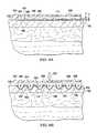
- FIG. 4Aillustrates a magnified view of a portion of the dressing shown in FIG. 1 without reduced pressure being applied;
- FIG. 4Billustrates a magnified view of a portion of the dressing shown in FIG. 1 with reduced pressure being applied;
- FIG. 5illustrates a cross-sectional view of an illustrative embodiment of a dressing for use in the reduced pressure treatment system of FIG. 1 with reduced pressure being applied;
- FIG. 6illustrates a cross-sectional view of an illustrative embodiment of a dressing for use in the reduced pressure treatment system of FIG. 1 with reduced pressure being applied;
- FIG. 7Aillustrates a cross-sectional view of an illustrative embodiment of a dressing for use in the reduced pressure treatment system of FIG. 1 without reduced pressure being applied;
- FIG. 7Billustrates a cross-sectional view of an illustrative embodiment of a dressing for use in the reduced pressure treatment system of FIG. 1 with reduced pressure being applied;
- FIG. 8Aillustrates a magnified view of a portion of the dressing shown in FIG. 7A ;
- FIG. 8Billustrates a magnified view of a portion of the dressing shown in FIG. 7B .
- reduced pressuregenerally refers to a pressure less than the ambient pressure at a tissue site that is being subjected to treatment. In most cases, this reduced pressure will be less than the atmospheric pressure at which the patient is located. Alternatively, the reduced pressure may be less than a hydrostatic pressure associated with tissue at the tissue site. Although the terms “vacuum” and “negative pressure” may be used to describe the pressure applied to the tissue site, the actual pressure reduction applied to the tissue site may be significantly less than the pressure reduction normally associated with a complete vacuum. Reduced pressure may initially generate fluid flow in the area of the tissue site. As the hydrostatic pressure around the tissue site approaches the desired reduced pressure, the flow may subside, and the reduced pressure is then maintained. Unless otherwise indicated, values of pressure stated herein are gauge pressures. Similarly, references to increases in reduced pressure typically refer to a decrease in absolute pressure, while decreases in reduced pressure typically refer to an increase in absolute pressure.
- the tissue treatment systems and methods described in this applicationimprove the treatment of a tissue site by increasing or improving granulation tissue development, thus allowing healing of a wound that may not otherwise heal with traditional treatment modalities, or in some cases, allowing an increased rate of healing of a wound.
- Granulationmay be promoted by exposing the tissue site to micro-mechanical stresses and strains.
- the tissue sitemay also be exposed to macro strains. While the creation of micro-mechanical stresses and strains at a tissue site may be provided by applying a reduced pressure to a sealed space adjacent the tissue site, the system and methods described herein may also employ the use of positive pressure or forces to create micro and macro stresses and strains.
- tissue sitemay refer to a wound, such as a wound 106 , or defect located on or within any tissue, including but not limited to, bone tissue, adipose tissue, muscle tissue, neural tissue, dermal tissue, vascular tissue, connective tissue, cartilage, tendons, or ligaments.
- tissue sitemay further refer to areas of any tissue that are not necessarily wounded or defective, but are instead areas in which it is desired to add or promote the growth of additional tissue.
- reduced pressure tissue treatmentmay be used in certain tissue areas to grow additional tissue that may be harvested and transplanted to another tissue location.
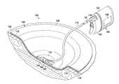
- the dressing 103includes a drape 108 , having a plurality of projections 112 extending from the drape 108 and positioned in contact with the tissue site 102 .
- the plurality of projections 112are configured to create microstrain at the tissue site 102 when reduced pressure is applied to stimulate the formation of granulation tissue.
- the drape 108is positioned over the tissue site 102 to create a sealed space 114 between the drape 108 and the tissue site 102 .
- the drape 108is configured to not only create the sealed space 114 , but to also stimulate the formation of granulation at the tissue site 102 .
- the dressing 103further includes a reduced pressure interface 110 fluidly coupling the drape 108 to the therapy unit 104 .
- the reduced pressure interface 110is fluidly coupled to the drape 108 to provide fluid access to the tissue site 102 .
- the drape 108includes an aperture 116 for providing fluid access to the reduced pressure interface 110 .
- a conduit 118fluidly couples the therapy unit 104 and the reduced pressure interface 110 .
- the reduced pressure interface 110is capable of delivering reduced pressure to the tissue site 102 .
- the therapy unit 104includes a fluid containment member 122 in fluid communication with a reduced pressure source 124 .
- the fluid containment member 122is a collection canister that includes a chamber for collecting fluids from the tissue site 102 .
- the fluid containment member 122alternatively could be an absorbent material or any other container, device, or material that is capable of collecting fluid.
- the conduit 118may be a multi-lumen tube that is capable of providing one or more conduits to deliver reduced pressure to the drape 108 and one or more conduits to sense the amount of pressure at the tissue site 102 . Liquids or exudates communicated from the drape 108 through the conduit 118 are removed from the conduit 118 and retained within the fluid containment member 122 .
- the reduced pressure source 124may an electrically-driven vacuum pump.
- the reduced pressure source 124may instead be a manually-actuated or manually-charged pump that does not require electrical power.
- the reduced pressure source 124may be one or more piezoelectric-actuated micropumps that may be positioned remotely from the dressing 103 , or at the dressing beneath or adjacent to the drape 108 .
- the reduced pressure source 124instead may be any other type of pump, or alternatively a wall suction port or air delivery port such as those available in hospitals and other medical facilities.
- the reduced pressure treatment system 100may further include a vent 120 in the conduit 118 configured to release the reduced pressure at the tissue site 102 over a selected amount of time.
- a sensor(not shown) positioned in the therapy unit 104 may receive data from the vent 120 .
- the sensorcommunicates with the processing unit.
- the measurements from the sensormay be used by the processing unit to determine a real-time rate of pressure decay as the reduced pressure is released through the vent 120 .
- the processing unitis configured to determine whether the drape 108 needs to be replaced due to the growth of granulation tissue or the accumulation of slough, i.e., dead tissue. More rapid rates of pressure decay may indicate that the drape 108 needs to be replaced.
- the decay of the reduced pressuremay be determined in several ways. For example, the decay may be determined by measuring a reduction in the reduced pressure (i.e. increase in absolute pressure) over a selected amount of time after opening the vent 120 . As another example, the decay may be determined by measuring the amount of time that is required for the reduced pressure to drop to a threshold pressure. The decay in reduced pressure may also be determined by measuring the reduction in the flow rate in the conduit 118 over the selected amount of time after opening the vent 120 . Other methods of measuring the decay of reduced pressure may also be used in a similar manner and are contemplated within the scope of the illustrative embodiments.
- the processing unitmay send an alert signal to an alarm when the drape 108 needs to be changed.
- the processing unitmay further indicate whether the drape 108 needs to be changed due to an accumulation of slough, or whether the drape 108 needs to be changed due to the growth of granulation tissue.
- the shape of the pressure-time curvewould distinguish between slough and granulation tissue. Slough tends to be softer than granulation tissue so when reduced pressure is applied to the drape 108 , more time would pass in reaching the set pressure when the drape 108 has been placed adjacent to slough. More time would pass to reach the set pressure due to the compression or creep of the slough as it is squeezed between the drape 108 and the tissue site 102 .
- the drape 108having a first side 128 and a second, tissue-facing side 130 , is positioned over the tissue site 102 .
- the plurality of projections 112are located on at least a portion of the second side 130 of the drape 108 and are configured to create microstrain at the tissue site 102 to promote granulation.
- the drape 108is comprised of a single layer.
- the drape 108may be a biomedical grade silicone or another flexible, biomedical material such as polyurethane (PU), and particularly a hydrophilic polyurethane, that may be easily removed from the tissue site 102 even in the presence of granulation formation.
- the materials used to form the drape 108may have elastic properties that assist in preventing the tissue site 102 from contracting when the drape 108 is stretched into the tissue site 102 under reduced pressure. In other words, the stretching of the drape 108 into the tissue site 102 creates macrostrain at the tissue site 102 that assists in preventing wound contraction.
- the material used to form the drape 108is substantially transparent to allow a healthcare provider to inspect the tissue site 102 without removing the drape 108 .
- the drape 108may be formed in a number of ways. In specific, non-limiting examples, the drape 108 may be formed by extrusion or molding.
- the drape 108may further include an adhesive layer (not explicitly shown).
- a linermay cover the adhesive layer to protect or preserve the adhesive layer prior to positioning the drape 108 at the tissue site 102 .
- the adhesive layeris positioned on the second side 130 of the drape 108 .
- the adhesive layermay contact only a portion of the second side 130 of the drape 108 , or the adhesive layer may contact the entire second side 130 of the drape 108 .
- the adhesive layeralso contacts the plurality of projections 112 located on the second side 130 of the drape 108 .
- the adhesive layeronly contacts areas of the second side 130 of the drape 108 where the plurality of projections 112 are absent.
- the adhesive layermay include silver or a hydrogel.
- the adhesive layermay be configured so that it dissolves in the presence of wound fluid.
- the adhesive layermay be inactive until it is contacted with a catalyst.
- an area adjacent to the tissue site 102such as a intact portion of the patient's epidermis 132 , may be treated with a catalyst so that when the adhesive layer from the drape 108 contacts the catalyst, the adhesive layer will adhere the drape 108 to the area treated with a catalyst.
- the catalystmay be applied directly to the adhesive layer prior to positioning the drape 108 against the tissue site 102 and the surrounding areas of the tissue site 102 .
- the catalystis a platinum catalyst and the drape 108 includes a silicone.
- the siliconeWhen the platinum catalyst and the silicone are brought into contact, the silicone polymerizes and crosslinks.
- the catalystis a multivalent salt such as calcium chloride or zinc chloride.
- the drape 108includes a polymer solution such as a sodium salt of an acrylic acid polymer. When the multivalent salt and the polymer solution are brought in contact, the multivalent salt crosslinks with the polymer.
- the plurality of projections 112may be flexible and may further be formed from a substantially gas impermeable material such as silicone. In one embodiment, the plurality of projections 112 may be formed from a semi-gas permeable material. Additionally, the plurality of projections 112 may be rigid. As stated above, the drape 108 may be made from silicone and since the plurality of projections 112 are part of the drape 108 , the plurality of projections 112 may also be formed of silicone. In one embodiment, the plurality of projections 112 are solid. In another embodiment, the plurality of projections 112 are hollow. The plurality of projections 112 may form a plurality of channels 137 to distribute reduced pressure and allow for fluid flow between the plurality of projections 112 .
- the plurality of projections 112are dimensioned to provide local load points at the tissue site 102 sufficient to create microstrain at the tissue site 102 for stimulating granulation formation when reduced pressure is applied.
- the pattern or position of the plurality of projections 112 on the drape 108may be uniform or non-uniform.
- the plurality of projections 112may come in a number of shapes. In specific, non-limiting examples, the plurality of projections 112 may be a spike, conical, pyramid, dome, oblong, cylindrical, or rectangular shape.
- the shape of each of the plurality of projections 112may be the same, or the shapes of each of the plurality of projections 112 may be different.
- the shapeswill occupy a volume described by cube volumes where the side of the cube would range between approximately 0.2 millimeters (mm) to 1.5 mm.
- the spike shapewould have a base length or diameter of about 0.2 mm and a vertical height of between 0.4 mm to 0.8 mm.
- the cone shapewould have a base diameter of about 0.4 mm and a vertical height of between 0.4 mm to 1.2 mm.
- the dome shapewould be a spherical cap or parabolic shape with a base diameter ranging from about 0.4 mm to 1 mm.
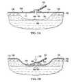
- FIG. 2Aillustrates the drape 108 loosely placed over the tissue site 102 prior to the application of reduced pressure.
- the drape 108extends beyond the perimeter of the tissue site 102 and contacts the intact portion of the patient's epidermis 132 .
- FIGS. 2A and 2Bshow the plurality of projections 112 contacting the intact portion of the patient's epidermis 132 .
- an adhesive layerseals the drape 108 to the intact portion of the patient's epidermis 132 , creating the sealed space 114 .
- FIG. 2Aillustrates the drape 108 loosely placed over the tissue site 102 prior to the application of reduced pressure.
- the drape 108extends beyond the perimeter of the tissue site 102 and contacts the intact portion of the patient's epidermis 132 .
- FIGS. 2A and 2Bshow the plurality of projections 112 contacting the intact portion of the patient's epidermis 132 .
- an adhesive layerseals the drape 108 to the intact portion of the patient
- FIG. 2Billustrates the drape 108 pressed into the tissue site 102 when reduced pressure has been applied to the sealed space 114 .
- Arrow 134represents the downward force exerted on the drape 108 when reduced pressure has been applied to the sealed space 114 .
- the reduced pressure applied to the sealed space 114not only causes the drape 108 to collapse into the tissue site 102 so that the plurality of projections 112 press into the tissue site 102 and create microstrain, the application of reduced pressure also causes the tissue site 102 to be pulled or sucked into the plurality of projections 112 .
- the plurality of channels 137 formed by the plurality of projections 112allow (1) the reduced pressure to be distributed across the tissue site 102 and (2) fluid to flow around the plurality of projections 112 .
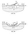
- FIG. 3Aillustrates the drape 108 loosely placed over the tissue site 102 prior to the application of reduced pressure.
- the drape 108extends beyond the perimeter of the tissue site 102 and contacts the intact portion of the patient's epidermis 132 .
- FIGS. 3A and 3Bshow the plurality of projections 112 being limited to an inner portion 140 of the drape 108 . Only an outer, smooth portion 142 of the drape 108 contacts the intact portion of the patient's epidermis 132 .
- the outer portion 142 of the drape 108may surround the inner portion 140 of the drape 108 .
- FIG. 3Billustrates the drape 108 pressed into the tissue site 102 when reduced pressure has been applied to the sealed space 114 .
- the arrow 134represents the downward force exerted on the drape 108 when reduced pressure has been applied to the sealed space 114 .
- the reduced pressure applied to the sealed space 114not only causes the drape 108 to collapse into the tissue site 102 so that the plurality of projections 112 press into the tissue site 102 and create microstrain, the application of reduced pressure also causes the tissue site 102 to be pulled or sucked into the plurality of projections 112 .
- the plurality of channels 137 formed by the plurality of projections 112allow (1) the reduced pressure to be distributed across the tissue site 102 and (2) fluid to flow around the plurality of projections 112 .
- FIG. 4Breduced pressure has been applied to the sealed space 114 .
- the arrow 134represents the force exerted on the drape 108 and, thus, the plurality of projections 112 from the reduced pressure.
- the arrow 134represents the force that causes the plurality of projections 112 to be pushed into the tissue site 102 .
- An arrow 136represents the suction force applied to the tissue site 102 by way of reduced pressure in the sealed space 114 .
- the arrow 136represents the force that causes the tissue site 102 to pull up against the plurality of projections 112 .
- Arrows 138may represent the flow of reduced pressure or fluids around the plurality of projections 112 through the plurality of channels 137 formed by the plurality of projections 112 .
- the drape 208is similar to the drape 108 illustrated in FIGS. 1-4B , except the drape 208 comprises multiple layers.
- the drape 208includes a first layer 244 fixed to a second layer 246 .
- the second layer 246may be referred to as a wound filler.
- the first layer 244may be fixed to the second layer 246 by way of bond, weld, adhesive, heat process, or other known connection means.
- the first layer 244has a first side 248 and a second side 250 .
- the second layer 246has a first side 252 and a second side 254 .
- the second side 248 of the first layer 244is fixed to the first side 252 of the second layer 246 .
- the second side 254 of the second layer 246includes a plurality of projections 212 .
- the plurality of projections 212are located on at least a portion of the second side 254 of the second layer 246 of the drape 208 .
- the plurality of projections 212are configured to create microstrain at the tissue site 102 to promote granulation.
- the second layermay be comprised of only the plurality of projections 212 , such that each of the plurality of projections 212 are individually fixed to the first layer 244 .
- the first and second layers 244 , 246 of the drape 208may be formed from a biomedical grade silicone or another flexible, biomedical material such as polyurethane (PU).
- PUpolyurethane
- the first and second layers 244 , 246may be formed from a hydrophilic polyurethane that may be easily removed from the tissue site 102 even in the presence of granulation formation.
- the first layer 244may be formed from the same material or a different material as the second layer 246 .
- the materials used to form the drape 208may have elastic properties that assist in preventing the tissue site 102 from contracting when the drape 208 is stretched into the tissue site 102 under reduced pressure.
- the stretching of the drape 208 into the tissue site 102creates macrostrain at the tissue site 102 that assists in preventing wound contraction.
- the material or materials used to form the drape 208are substantially transparent to allow a healthcare provider to inspect the tissue site 102 without removing the drape 208 .
- the drape 208may be formed in a number of ways. In specific, non-limiting examples, the drape 208 may be formed by extrusion or molding.
- the drape 208may further include an adhesive layer (not explicitly shown).
- a linermay cover the adhesive layer to protect or preserve the adhesive layer prior to positioning the drape 208 at the tissue site 102 .
- the adhesive layeris positioned on the second side 252 of the second layer 246 of the drape 208 .
- the adhesive layermay contact only a portion of the second side 252 of the second layer 246 , or the adhesive layer may contact the entire second side 252 of the drape 208 .
- the adhesive layeralso contacts the plurality of projections 212 located on the second side 252 of the second layer 246 .
- the adhesive layeronly contacts areas of the second side 252 of the second layer 246 where the plurality of projections 212 are absent.
- the adhesive layermay include silver or a hydrogel.
- the adhesive layermay be configured so that it dissolves in the presence of wound fluid.
- the adhesive layermay be inactive until it is contacted with a catalyst.
- an area over to the tissue site 102such as the intact portion of the patient's epidermis 132 , may be treated with a catalyst so that when the adhesive layer from the drape 208 contacts the catalyst, the adhesive layer will adhere the drape 208 to the area treated with a catalyst.
- the catalystmay be applied directly to the adhesive layer prior to positioning the drape 208 against the tissue site 102 and the surrounding areas of the tissue site 102 .
- the catalystis a platinum catalyst and the drape 208 includes a silicone.
- the siliconeWhen the platinum catalyst and the silicone are brought into contact, the silicone polymerizes and crosslinks.
- the catalystis a multivalent salt such as calcium chloride or zinc chloride.
- the drape 208includes a polymer solution such as a sodium salt of an acrylic acid polymer. When the multivalent salt and the polymer solution are brought in contact, the multivalent salt crosslinks with the polymer.
- the plurality of projections 212may be flexible and may further be formed from a substantially gas impermeable material such as silicone. A substantially gas impermeable material may also include a semi-permeable material. In one embodiment, the plurality of projections 212 are rigid. In one embodiment, the plurality of projections 212 are solid. In another embodiment, the plurality of projections 212 are hollow. The plurality of projections 212 form a plurality of channels 237 to distribute reduced pressure and allow for fluid flow between the plurality of projections 212 . The plurality of projections 212 are dimensioned to provide local load points at the tissue site 102 sufficient to create microstrain at the tissue site 102 for stimulating granulation formation.
- the pattern or position of the plurality of projections 212 on the drape 208may be uniform or non-uniform.
- the plurality of projections 212may come in a number of shapes.
- the plurality of projections 212may be a spike, conical, pyramid, dome, or oblong shape.
- the shape of each of the plurality of projections 212may be the same, or the shapes of each of the plurality of projections 212 may be different.
- a dressing 203which includes the drape 208 , is shown covering the tissue site 102 .
- the drape 208extends beyond the perimeter of the tissue site 102 and contacts the intact portion of the patient's epidermis 132 .
- FIG. 5shows the plurality of projections 212 contacting the intact portion of the patient's epidermis 132 .
- an adhesive layerseals the drape 208 to the intact portion of the patient's epidermis 132 , creating a sealed space 214 .
- FIG. 5illustrates the drape 208 pressed into the tissue site 102 when reduced pressure has been applied to the sealed space 214 .
- Arrow 234represents the downward force exerted on the drape 208 when reduced pressure has been applied to the sealed space 214 .
- the reduced pressure applied to the sealed space 214not only causes the drape 208 to collapse into the tissue site 102 so that the plurality of projections 212 press into the tissue site 102 and create microstrain, the application of reduced pressure also causes the tissue site 102 to be pulled or sucked into the plurality of projections 212 .
- the plurality of channels 237 formed by the plurality of projections 212allow (1) the reduced pressure to be distributed across the tissue site 102 and (2) fluid to flow around the plurality of projections 212 .
- the dressing 203which includes the drape 208 , is shown covering the tissue site 102 .
- the drape 208extends beyond the perimeter of the tissue site 102 and contacts the intact portion of the patient's epidermis 132 .
- FIG. 6shows the plurality of projections 212 being limited to an inner portion 240 of the drape 208 . Only an outer, smooth portion 242 of the drape 208 contacts the intact portion of the patient's epidermis 132 .
- the outer portion 242 of the drape 208may surround the inner portion 240 of the drape 208 .
- the adhesive layerseals the drape 208 to the intact portion of the patient's epidermis 132 , creating the sealed space 214 .
- FIG. 6illustrates the drape 208 pressed into the tissue site 102 when reduced pressure has been applied to the sealed space 214 .
- the arrow 234represents the downward force exerted on the drape 208 when reduced pressure has been applied to the sealed space 214 .
- the reduced pressure applied to the sealed space 214not only causes the drape 208 to collapse into the tissue site 102 so that the plurality of projections 212 press into the tissue site 102 and create microstrain, the application of reduced pressure also causes the tissue site 102 to be pulled or sucked into the plurality of projections 212 .
- the plurality of channels 237 formed by the projections 212allow (1) the reduced pressure to be distributed across the tissue site 102 and (2) fluid to flow around the plurality of projections 212 .
- the drape 308is a multi-layer drape for positioning over the tissue site 102 and is configured to (1) provide a sealed space 314 between the drape 308 and the tissue site 102 and (2) promote granulation at the tissue site 102 .
- the drape 308may include an adhesive layer for attaching the drape 308 to the tissue site 102 or the intact portion of the patient's epidermis 132 to create the sealed space 314 .
- the reduced pressure interface 110may be connected to the drape 308 to allow reduced pressure to be applied to the sealed space 314 .
- the drape 308includes an aperture 316 that allows communication between the reduced pressure interface 110 and the sealed space 314 .
- the drape 308includes a first layer 340 and a second layer 342 connected to the first layer 340 that forms an inner space 344 between the first layer 340 and the second layer 342 .
- the second layer 342is capable of forming a plurality of projections 312 in the presence of a biasing force represented by arrows 346 .
- the plurality of projections 312are formed in the presence of the biasing force by extending from the second layer 342 .
- the biasing forceis a positive pressure.
- the drape 308includes one or more positive pressure interfaces 348 , or pressurization ports.
- the positive pressure interface 348is in fluid communication with the inner space 344 .
- the positive pressure interface 348may be positioned on or attached to the first layer 340 .
- the positive pressure interface 348allows positive pressure from a positive pressure source (not shown) to be delivered to the inner space 344 .
- the plurality of projections 312are formed when a positive pressure, p 1 , within the inner space 344 is greater than a threshold pressure.
- the distance to which the plurality of projections 312 extend from the second layer 342depends on the level of the positive pressure, p 1 , within the inner space 344 that is beyond the threshold pressure.
- the plurality of projections 312may be formed by a number of shapes as previously disclosed with reference to the plurality of projections 112 .
- the shape of the plurality of projections 312 when extended from the second layer 342will occupy a volume described by cube volumes where the side of the cube would range between approximately 0.2 millimeters (mm) to 1.5 mm.
- the spike shapewould have a base length or diameter of about 0.2 mm and a vertical height of between 0.4 mm to 0.8 mm.
- the cone shapewould have a base diameter of about 0.4 mm and a vertical height of between 0.4 mm to 1.2 mm.
- the dome shapewould be a spherical cap or parabolic shape with a base diameter ranging from about 0.4 mm to 1 mm.
- the second layer 342includes a first plurality of sections 350 having a first thickness, t 1 , and a second plurality of sections 352 having a second thickness, t 2 .
- the second thickness, t 2is less than the first thickness, t 1 .
- the second plurality of sections 352are configured to form the plurality of projections 312 in the presence of the biasing force.
- the first layer 340 and the second layer 342may be formed from the same material.
- the first layer 340 and the second layer 342may be formed from silicone or another flexible biomedical material that can be easily removed from the tissue site 102 even in the presence of granulation formation.
- FIGS. 7A and 7Ba dressing 303 that includes the drape 308 and the reduced pressure interface 110 is shown covering the tissue site 102 .
- FIG. 7Aillustrates the drape 308 loosely placed over the tissue site 102 prior to the application of reduced pressure to the sealed space 314 and prior to the application of positive pressure to the inner space 344 .
- the drape 308extends beyond the perimeter of the tissue site 102 and contacts the intact portion of the patient's epidermis 132 . While FIG.
- FIG. 7Bshows the plurality of projections 312 contacting the intact portion of the patient's epidermis 132 , it should be appreciated that the plurality of projections 312 may be limited to an inner portion of the drape 308 and only an outer, smooth portion of the drape 308 contacts the intact portion of the patient's epidermis 132 .
- the adhesive layerseals the drape 308 to the intact portion of the patient's epidermis 132 , creating the sealed space 314 .
- FIG. 7Billustrates the drape 308 after reduced pressure has been applied to the sealed space 314 and after positive pressure has been applied to the inner space 344 at sufficient levels to extend the plurality of projections 312 .
- FIG. 7Bshows the plurality of projections 312 pressed against the tissue site 102 .
- Arrow 334represents the downward force exerted on the drape 308 when reduced pressure has been applied to the sealed space 114 .
- the arrows 346represent the force exerted on the plurality of projections 312 created by the positive pressure.
- the reduced pressure applied to the sealed space 314not only causes the drape 308 to collapse into the tissue site 102 so that the plurality of projections 312 press into the tissue site 102 and create microstrain, the application of reduced pressure also causes the tissue site 102 to be pulled or sucked into the plurality of projections 312 .
- FIGS. 8A and 8Ba detailed view of a portion the drape 308 is presented.
- FIG. 8Ais a detailed view of the drape 308 positioned over to the tissue site 102 prior to reduced pressure being applied.
- FIG. 8Bis a detailed view of the drape 308 positioned over to the tissue site 102 after reduced pressure has been applied to the sealed space 314 and after positive pressure has been applied to the inner space 344 at sufficient levels to form the plurality of projections 312 .
Landscapes
- Health & Medical Sciences (AREA)
- Heart & Thoracic Surgery (AREA)
- General Health & Medical Sciences (AREA)
- Veterinary Medicine (AREA)
- Public Health (AREA)
- Life Sciences & Earth Sciences (AREA)
- Animal Behavior & Ethology (AREA)
- Engineering & Computer Science (AREA)
- Vascular Medicine (AREA)
- Biomedical Technology (AREA)
- Hematology (AREA)
- Anesthesiology (AREA)
- Chemical & Material Sciences (AREA)
- Epidemiology (AREA)
- Materials Engineering (AREA)
- Chemical Kinetics & Catalysis (AREA)
- Surgery (AREA)
- Media Introduction/Drainage Providing Device (AREA)
- Surgical Instruments (AREA)
- Materials For Medical Uses (AREA)
Abstract
Description
Claims (8)
Priority Applications (3)
| Application Number | Priority Date | Filing Date | Title |
|---|---|---|---|
| US13/311,893US9440010B2 (en) | 2010-12-07 | 2011-12-06 | Drape having microstrain inducing projections for treating a wound site |
| US15/234,624US10849791B2 (en) | 2010-12-07 | 2016-08-11 | Drape having microstrain inducing projections for treating a wound site |
| US17/074,024US20210030598A1 (en) | 2010-12-07 | 2020-10-19 | Drape having microstrain inducing projections for treating a wound site |
Applications Claiming Priority (2)
| Application Number | Priority Date | Filing Date | Title |
|---|---|---|---|
| US42067810P | 2010-12-07 | 2010-12-07 | |
| US13/311,893US9440010B2 (en) | 2010-12-07 | 2011-12-06 | Drape having microstrain inducing projections for treating a wound site |
Related Child Applications (1)
| Application Number | Title | Priority Date | Filing Date |
|---|---|---|---|
| US15/234,624ContinuationUS10849791B2 (en) | 2010-12-07 | 2016-08-11 | Drape having microstrain inducing projections for treating a wound site |
Publications (2)
| Publication Number | Publication Date |
|---|---|
| US20120143114A1 US20120143114A1 (en) | 2012-06-07 |
| US9440010B2true US9440010B2 (en) | 2016-09-13 |
Family
ID=45390197
Family Applications (5)
| Application Number | Title | Priority Date | Filing Date |
|---|---|---|---|
| US13/311,873Active2034-03-16US9352075B2 (en) | 2010-12-07 | 2011-12-06 | Wound healing apparatus for promoting granulation and epithelialization at a tissue site |
| US13/311,893Active2035-07-14US9440010B2 (en) | 2010-12-07 | 2011-12-06 | Drape having microstrain inducing projections for treating a wound site |
| US15/057,760AbandonedUS20160220742A1 (en) | 2010-12-07 | 2016-03-01 | Wound Healing Apparatus For Promoting Granulation And Epithelialisation At A Tissue Site |
| US15/234,624Active2035-01-27US10849791B2 (en) | 2010-12-07 | 2016-08-11 | Drape having microstrain inducing projections for treating a wound site |
| US17/074,024AbandonedUS20210030598A1 (en) | 2010-12-07 | 2020-10-19 | Drape having microstrain inducing projections for treating a wound site |
Family Applications Before (1)
| Application Number | Title | Priority Date | Filing Date |
|---|---|---|---|
| US13/311,873Active2034-03-16US9352075B2 (en) | 2010-12-07 | 2011-12-06 | Wound healing apparatus for promoting granulation and epithelialization at a tissue site |
Family Applications After (3)
| Application Number | Title | Priority Date | Filing Date |
|---|---|---|---|
| US15/057,760AbandonedUS20160220742A1 (en) | 2010-12-07 | 2016-03-01 | Wound Healing Apparatus For Promoting Granulation And Epithelialisation At A Tissue Site |
| US15/234,624Active2035-01-27US10849791B2 (en) | 2010-12-07 | 2016-08-11 | Drape having microstrain inducing projections for treating a wound site |
| US17/074,024AbandonedUS20210030598A1 (en) | 2010-12-07 | 2020-10-19 | Drape having microstrain inducing projections for treating a wound site |
Country Status (3)
| Country | Link |
|---|---|
| US (5) | US9352075B2 (en) |
| TW (1) | TW201233373A (en) |
| WO (2) | WO2012078556A2 (en) |
Cited By (7)
| Publication number | Priority date | Publication date | Assignee | Title |
|---|---|---|---|---|
| US20180303967A1 (en)* | 2017-04-25 | 2018-10-25 | Ethicon, Inc. | Skin Closure Devices with Self-forming Exudate Drainage Channels |
| US11413370B2 (en) | 2004-02-18 | 2022-08-16 | Ethicon, Inc. | Adhesive-containing wound closure device and method |
| US11446407B2 (en) | 2004-07-12 | 2022-09-20 | Ethicon, Inc. | Adhesive-containing wound closure device and method |
| USD979768S1 (en) | 2016-09-29 | 2023-02-28 | Ethicon, Inc. | Release paper for wound treatment devices |
| US11679034B2 (en) | 2016-09-29 | 2023-06-20 | Ethicon, Inc. | Methods and devices for skin closure |
| US11883264B2 (en) | 2017-03-23 | 2024-01-30 | Ethicon, Inc. | Skin closure systems and devices of improved flexibility and stretchability for bendable joints |
| US11974734B2 (en) | 2018-07-31 | 2024-05-07 | Ethicon, Inc. | Skin closure devices with interrupted closure |
Families Citing this family (66)
| Publication number | Priority date | Publication date | Assignee | Title |
|---|---|---|---|---|
| US9820888B2 (en) | 2006-09-26 | 2017-11-21 | Smith & Nephew, Inc. | Wound dressing |
| AU2012212070A1 (en) | 2011-02-04 | 2013-09-19 | University Of Massachusetts | Negative pressure wound closure device |
| US9421132B2 (en) | 2011-02-04 | 2016-08-23 | University Of Massachusetts | Negative pressure wound closure device |
| MX364446B (en) | 2011-04-15 | 2019-04-26 | Univ Massachusetts | Surgical cavity drainage and closure system. |
| WO2013066426A2 (en)* | 2011-06-24 | 2013-05-10 | Kci Licensing, Inc. | Reduced-pressure dressings employing tissue-fixation elements |
| JP6348065B2 (en)* | 2011-12-07 | 2018-06-27 | ケーシーアイ ライセンシング インコーポレイテッド | Granulation synthetic gauze for use with a vacuum treatment system |
| USD733896S1 (en) | 2012-05-04 | 2015-07-07 | Genadyne Biotechnologies, Inc. | Abdominal dressing |
| EP2852333B1 (en) | 2012-05-22 | 2021-12-15 | Smith & Nephew plc | Apparatuses for wound therapy |
| EP2852419B1 (en) | 2012-05-22 | 2019-11-20 | Smith & Nephew plc | Wound closure device |
| AU2013264937B2 (en) | 2012-05-24 | 2018-04-19 | Smith & Nephew Inc. | Devices and methods for treating and closing wounds with negative pressure |
| MX369689B (en) | 2012-07-16 | 2019-11-19 | Smith & Nephew Inc | Negative pressure wound closure device. |
| US9623159B2 (en)* | 2012-08-03 | 2017-04-18 | Kci Licensing, Inc. | Interfaces, systems, and methods for use in reduced pressure tissue treatment |
| US10124098B2 (en) | 2013-03-13 | 2018-11-13 | Smith & Nephew, Inc. | Negative pressure wound closure device and systems and methods of use in treating wounds with negative pressure |
| BR112015021123A2 (en) | 2013-03-14 | 2017-07-18 | Smith & Nephew | compressible wound fillers and systems and methods for use in treating negative pressure injuries |
| US8893721B2 (en)* | 2013-03-15 | 2014-11-25 | Futrell Medical Corporation | Surgical drape with vapor evacuation |
| EP2815731A1 (en)* | 2013-06-18 | 2014-12-24 | Mölnlycke Health Care AB | Fluid transport dressing |
| CA2918157A1 (en) | 2013-07-16 | 2015-01-22 | Smith & Nephew Plc | Apparatus for wound therapy |
| CN106170275B (en) | 2013-10-21 | 2021-05-07 | 史密夫和内修有限公司 | Negative pressure wound closure device |
| AU2015208299B2 (en) | 2014-01-21 | 2019-11-21 | Smith & Nephew Plc | Collapsible dressing for negative pressure wound treatment |
| EP3096725B1 (en) | 2014-01-21 | 2023-10-18 | Smith & Nephew plc | Wound treatment apparatuses |
| US10226566B2 (en) | 2014-04-23 | 2019-03-12 | Genadyne Biotechnologies, Inc. | System and process for removing bodily fluids from a body opening |
| US10898217B2 (en) | 2014-05-09 | 2021-01-26 | Kci Licensing, Inc. | Dressing providing apertures with multiple orifice sizes for negative-pressure therapy |
| WO2015172111A1 (en) | 2014-05-09 | 2015-11-12 | Kci Licensing, Inc. | Disruptive dressing for use with negative pressure and fluid instillation |
| JP6728062B2 (en)* | 2014-05-09 | 2020-07-22 | ケーシーアイ ライセンシング インコーポレイテッド | Debriding dressings for use with negative pressure and fluid drip |
| WO2015172108A1 (en) | 2014-05-09 | 2015-11-12 | Kci Licensing, Inc. | Dressing with contracting layer for linear tissue sites |
| US11007082B2 (en)* | 2014-07-23 | 2021-05-18 | Innovative Therapies Inc. | Foam laminate dressing |
| GB2536264B (en)* | 2015-03-11 | 2017-11-08 | Timothy Jake | Graduated pressure applicator |
| AU2016254119A1 (en) | 2015-04-29 | 2017-10-05 | Smith & Nephew Inc. | Negative pressure wound closure device |
| US11471586B2 (en) | 2015-12-15 | 2022-10-18 | University Of Massachusetts | Negative pressure wound closure devices and methods |
| US10575991B2 (en) | 2015-12-15 | 2020-03-03 | University Of Massachusetts | Negative pressure wound closure devices and methods |
| US10814049B2 (en) | 2015-12-15 | 2020-10-27 | University Of Massachusetts | Negative pressure wound closure devices and methods |
| TWI615163B (en)* | 2016-01-12 | 2018-02-21 | 富強醫材股份有限公司 | Closed-wound drainage device |
| WO2017132144A1 (en)* | 2016-01-28 | 2017-08-03 | Kci Licensing, Inc. | Sequential collapse waveform dressing |
| JP7038701B2 (en) | 2016-08-30 | 2022-03-18 | スミス アンド ネフュー ピーエルシー | System for applying decompression therapy |
| US11096832B2 (en) | 2016-09-27 | 2021-08-24 | Smith & Nephew Plc | Wound closure devices with dissolvable portions |
| CN110167495B (en) | 2016-11-02 | 2022-06-14 | 史密夫和内修有限公司 | Wound closure device |
| AU2018231771A1 (en)* | 2017-03-09 | 2019-09-26 | Secretary, Department Of Biotechnology | A wound dressing for combined negative pressure and fluid delivery system |
| US10695227B2 (en) | 2017-06-07 | 2020-06-30 | Kci Licensing, Inc. | Methods for manufacturing and assembling dual material tissue interface for negative-pressure therapy |
| AU2018282188A1 (en) | 2017-06-07 | 2019-12-19 | 3M Innovative Properties Company | Tissue contact interface |
| WO2018226691A1 (en) | 2017-06-07 | 2018-12-13 | Kci Licensing, Inc. | Methods for manufacturing and assembling dual material tissue interface for negative-pressure therapy |
| AU2018282159A1 (en) | 2017-06-07 | 2019-12-19 | 3M Innovative Properties Company | Composite dressings for improved granulation and reduced maceration with negative-pressure treatment |
| WO2018226744A1 (en) | 2017-06-07 | 2018-12-13 | Kci Licensing, Inc. | Peel and place dressing for negative -pressure treatment |
| EP3634334B1 (en) | 2017-06-07 | 2023-05-24 | 3M Innovative Properties Company | Multi-layer wound filler for extended wear time |
| JP7204685B2 (en) | 2017-06-07 | 2023-01-16 | スリーエム イノベイティブ プロパティズ カンパニー | A composite dressing that promotes granulation formation and reduces maceration in negative pressure therapy |
| WO2018226650A1 (en) | 2017-06-07 | 2018-12-13 | Kci Licensing, Inc. | Systems, apparatuses, and methods for negative-pressure treatment with reduced tissue in-growth |
| WO2018226707A1 (en) | 2017-06-07 | 2018-12-13 | Kci Licensing, Inc. | Composite dressings for improved granulation reduced maceration with negative-pressure treatment |
| WO2018229009A1 (en) | 2017-06-13 | 2018-12-20 | Smith & Nephew Plc | Wound closure device and method of use |
| EP3638169B1 (en) | 2017-06-13 | 2024-11-13 | Smith & Nephew PLC | Collapsible structure and method of use |
| WO2018229011A1 (en) | 2017-06-14 | 2018-12-20 | Smith & Nephew Plc | Collapsible structure for wound closure and method of use |
| WO2018231874A1 (en) | 2017-06-14 | 2018-12-20 | Smith & Nephew, Inc. | Control of wound closure and fluid removal management in wound therapy |
| AU2018285239B2 (en) | 2017-06-14 | 2023-09-21 | Smith & Nephew Plc | Collapsible sheet for wound closure and method of use |
| US11123476B2 (en) | 2017-06-14 | 2021-09-21 | Smith & Nephew, Inc. | Fluid removal management and control of wound closure in wound therapy |
| WO2019020544A1 (en) | 2017-07-27 | 2019-01-31 | Smith & Nephew Plc | Customizable wound closure device and method of use |
| US11590030B2 (en) | 2017-08-07 | 2023-02-28 | Smith & Nephew Plc | Wound closure device with protective layer and method of use |
| EP3675925A1 (en) | 2017-08-29 | 2020-07-08 | Smith & Nephew PLC | Systems and methods for monitoring wound closure |
| US12004926B2 (en)* | 2017-09-18 | 2024-06-11 | Kci Licensing, Inc. | Wound dressings and systems with remote oxygen generation for topical wound therapy and related methods |
| WO2019084006A1 (en)* | 2017-10-23 | 2019-05-02 | Kci Licensing, Inc. | Low profile distribution components for wound therapy |
| JP2022506830A (en)* | 2018-11-08 | 2022-01-17 | ケーシーアイ ライセンシング インコーポレイテッド | Dressing with a protruding layer that allows cleaning of wound bed macrodeformations |
| EP3880268B1 (en)* | 2018-11-14 | 2024-09-11 | Solventum Intellectual Properties Company | Wound therapy system with blockage and leak detection |
| US12409072B2 (en) | 2019-12-05 | 2025-09-09 | Kci Manufacturing Unlimited Company | Multi-layer negative pressure incisional wound therapy dressing |
| US11160917B2 (en)* | 2020-01-22 | 2021-11-02 | J&M Shuler Medical Inc. | Negative pressure wound therapy barrier |
| USD992121S1 (en) | 2020-11-09 | 2023-07-11 | Coram Deo LLC | Umbilical cord cover |
| WO2023021429A1 (en)* | 2021-08-17 | 2023-02-23 | Fisher & Paykel Healthcare Limited | Apparatus for supplying fluid to a tissue area |
| USD1095846S1 (en) | 2022-08-17 | 2025-09-30 | Fisher & Paykel Healthcare Limited | Tissue care device |
| WO2024171120A1 (en)* | 2023-02-16 | 2024-08-22 | Fisher & Paykel Healthcare Limited | "apparatus for supplying fluid to a tissue area" |
| USD1094725S1 (en) | 2023-07-11 | 2025-09-23 | Fisher & Paykel Healthcare Limited | Tissue care device |
Citations (107)
| Publication number | Priority date | Publication date | Assignee | Title |
|---|---|---|---|---|
| US1355846A (en) | 1920-02-06 | 1920-10-19 | David A Rannells | Medical appliance |
| US2547758A (en) | 1949-01-05 | 1951-04-03 | Wilmer B Keeling | Instrument for treating the male urethra |
| US2632443A (en) | 1949-04-18 | 1953-03-24 | Eleanor P Lesher | Surgical dressing |
| US2682873A (en) | 1952-07-30 | 1954-07-06 | Johnson & Johnson | General purpose protective dressing |
| US2910763A (en) | 1955-08-17 | 1959-11-03 | Du Pont | Felt-like products |
| US2969057A (en) | 1957-11-04 | 1961-01-24 | Brady Co W H | Nematodic swab |
| US3066672A (en) | 1960-09-27 | 1962-12-04 | Jr William H Crosby | Method and apparatus for serial sampling of intestinal juice |
| US3367332A (en) | 1965-08-27 | 1968-02-06 | Gen Electric | Product and process for establishing a sterile area of skin |
| US3520300A (en) | 1967-03-15 | 1970-07-14 | Amp Inc | Surgical sponge and suction device |
| US3568675A (en) | 1968-08-30 | 1971-03-09 | Clyde B Harvey | Fistula and penetrating wound dressing |
| US3648692A (en) | 1970-12-07 | 1972-03-14 | Parke Davis & Co | Medical-surgical dressing for burns and the like |
| US3682180A (en) | 1970-06-08 | 1972-08-08 | Coilform Co Inc | Drain clip for surgical drain |
| US3826254A (en) | 1973-02-26 | 1974-07-30 | Verco Ind | Needle or catheter retaining appliance |
| US4080970A (en) | 1976-11-17 | 1978-03-28 | Miller Thomas J | Post-operative combination dressing and internal drain tube with external shield and tube connector |
| US4096853A (en) | 1975-06-21 | 1978-06-27 | Hoechst Aktiengesellschaft | Device for the introduction of contrast medium into an anus praeter |
| US4139004A (en) | 1977-02-17 | 1979-02-13 | Gonzalez Jr Harry | Bandage apparatus for treating burns |
| US4165748A (en) | 1977-11-07 | 1979-08-28 | Johnson Melissa C | Catheter tube holder |
| US4184510A (en) | 1977-03-15 | 1980-01-22 | Fibra-Sonics, Inc. | Valued device for controlling vacuum in surgery |
| US4233969A (en) | 1976-11-11 | 1980-11-18 | Lock Peter M | Wound dressing materials |
| US4245630A (en) | 1976-10-08 | 1981-01-20 | T. J. Smith & Nephew, Ltd. | Tearable composite strip of materials |
| US4256109A (en) | 1978-07-10 | 1981-03-17 | Nichols Robert L | Shut off valve for medical suction apparatus |
| US4261363A (en) | 1979-11-09 | 1981-04-14 | C. R. Bard, Inc. | Retention clips for body fluid drains |
| US4275721A (en) | 1978-11-28 | 1981-06-30 | Landstingens Inkopscentral Lic, Ekonomisk Forening | Vein catheter bandage |
| US4284079A (en) | 1979-06-28 | 1981-08-18 | Adair Edwin Lloyd | Method for applying a male incontinence device |
| US4297995A (en) | 1980-06-03 | 1981-11-03 | Key Pharmaceuticals, Inc. | Bandage containing attachment post |
| US4333468A (en) | 1980-08-18 | 1982-06-08 | Geist Robert W | Mesentery tube holder apparatus |
| US4373519A (en) | 1981-06-26 | 1983-02-15 | Minnesota Mining And Manufacturing Company | Composite wound dressing |
| US4382441A (en) | 1978-12-06 | 1983-05-10 | Svedman Paul | Device for treating tissues, for example skin |
| US4392853A (en) | 1981-03-16 | 1983-07-12 | Rudolph Muto | Sterile assembly for protecting and fastening an indwelling device |
| US4392858A (en) | 1981-07-16 | 1983-07-12 | Sherwood Medical Company | Wound drainage device |
| US4419097A (en) | 1981-07-31 | 1983-12-06 | Rexar Industries, Inc. | Attachment for catheter tube |
| US4465485A (en) | 1981-03-06 | 1984-08-14 | Becton, Dickinson And Company | Suction canister with unitary shut-off valve and filter features |
| EP0117632A2 (en) | 1983-01-27 | 1984-09-05 | Johnson & Johnson Products Inc. | Adhesive film dressing |
| US4475909A (en) | 1982-05-06 | 1984-10-09 | Eisenberg Melvin I | Male urinary device and method for applying the device |
| US4480638A (en) | 1980-03-11 | 1984-11-06 | Eduard Schmid | Cushion for holding an element of grafted skin |
| US4525166A (en) | 1981-11-21 | 1985-06-25 | Intermedicat Gmbh | Rolled flexible medical suction drainage device |
| US4525374A (en) | 1984-02-27 | 1985-06-25 | Manresa, Inc. | Treating hydrophobic filters to render them hydrophilic |
| US4540412A (en) | 1983-07-14 | 1985-09-10 | The Kendall Company | Device for moist heat therapy |
| US4543100A (en) | 1983-11-01 | 1985-09-24 | Brodsky Stuart A | Catheter and drain tube retainer |
| US4548202A (en) | 1983-06-20 | 1985-10-22 | Ethicon, Inc. | Mesh tissue fasteners |
| US4551139A (en) | 1982-02-08 | 1985-11-05 | Marion Laboratories, Inc. | Method and apparatus for burn wound treatment |
| US4569348A (en) | 1980-02-22 | 1986-02-11 | Velcro Usa Inc. | Catheter tube holder strap |
| US4605399A (en) | 1984-12-04 | 1986-08-12 | Complex, Inc. | Transdermal infusion device |
| US4608041A (en) | 1981-10-14 | 1986-08-26 | Frese Nielsen | Device for treatment of wounds in body tissue of patients by exposure to jets of gas |
| US4640688A (en) | 1985-08-23 | 1987-02-03 | Mentor Corporation | Urine collection catheter |
| US4655754A (en) | 1984-11-09 | 1987-04-07 | Stryker Corporation | Vacuum wound drainage system and lipids baffle therefor |
| US4664662A (en) | 1984-08-02 | 1987-05-12 | Smith And Nephew Associated Companies Plc | Wound dressing |
| US4710165A (en) | 1985-09-16 | 1987-12-01 | Mcneil Charles B | Wearable, variable rate suction/collection device |
| US4733659A (en) | 1986-01-17 | 1988-03-29 | Seton Company | Foam bandage |
| GB2195255A (en) | 1986-09-30 | 1988-04-07 | Vacutec Uk Limited | Method and apparatus for vacuum treatment of an epidermal surface |
| US4743232A (en) | 1986-10-06 | 1988-05-10 | The Clinipad Corporation | Package assembly for plastic film bandage |
| US4758220A (en) | 1985-09-26 | 1988-07-19 | Alcon Laboratories, Inc. | Surgical cassette proximity sensing and latching apparatus |
| US4787888A (en) | 1987-06-01 | 1988-11-29 | University Of Connecticut | Disposable piezoelectric polymer bandage for percutaneous delivery of drugs and method for such percutaneous delivery (a) |
| US4826494A (en) | 1984-11-09 | 1989-05-02 | Stryker Corporation | Vacuum wound drainage system |
| US4838883A (en) | 1986-03-07 | 1989-06-13 | Nissho Corporation | Urine-collecting device |
| US4840187A (en) | 1986-09-11 | 1989-06-20 | Bard Limited | Sheath applicator |
| US4863449A (en) | 1987-07-06 | 1989-09-05 | Hollister Incorporated | Adhesive-lined elastic condom cathether |
| US4872450A (en) | 1984-08-17 | 1989-10-10 | Austad Eric D | Wound dressing and method of forming same |
| US4878901A (en) | 1986-10-10 | 1989-11-07 | Sachse Hans Ernst | Condom catheter, a urethral catheter for the prevention of ascending infections |
| US4897081A (en) | 1984-05-25 | 1990-01-30 | Thermedics Inc. | Percutaneous access device |
| US4906240A (en) | 1988-02-01 | 1990-03-06 | Matrix Medica, Inc. | Adhesive-faced porous absorbent sheet and method of making same |
| US4906233A (en) | 1986-05-29 | 1990-03-06 | Terumo Kabushiki Kaisha | Method of securing a catheter body to a human skin surface |
| US4919654A (en) | 1988-08-03 | 1990-04-24 | Kalt Medical Corporation | IV clamp with membrane |
| US4941882A (en) | 1987-03-14 | 1990-07-17 | Smith And Nephew Associated Companies, P.L.C. | Adhesive dressing for retaining a cannula on the skin |
| US4953565A (en) | 1986-11-26 | 1990-09-04 | Shunro Tachibana | Endermic application kits for external medicines |
| US4969880A (en) | 1989-04-03 | 1990-11-13 | Zamierowski David S | Wound dressing and treatment method |
| US4985019A (en) | 1988-03-11 | 1991-01-15 | Michelson Gary K | X-ray marker |
| US5037397A (en) | 1985-05-03 | 1991-08-06 | Medical Distributors, Inc. | Universal clamp |
| US5086170A (en) | 1989-01-16 | 1992-02-04 | Roussel Uclaf | Process for the preparation of azabicyclo compounds |
| US5092858A (en) | 1990-03-20 | 1992-03-03 | Becton, Dickinson And Company | Liquid gelling agent distributor device |
| US5100396A (en) | 1989-04-03 | 1992-03-31 | Zamierowski David S | Fluidic connection system and method |
| US5134994A (en) | 1990-02-12 | 1992-08-04 | Say Sam L | Field aspirator in a soft pack with externally mounted container |
| US5149331A (en) | 1991-05-03 | 1992-09-22 | Ariel Ferdman | Method and device for wound closure |
| US5167613A (en) | 1992-03-23 | 1992-12-01 | The Kendall Company | Composite vented wound dressing |
| US5176663A (en) | 1987-12-02 | 1993-01-05 | Pal Svedman | Dressing having pad with compressibility limiting elements |
| US5215522A (en) | 1984-07-23 | 1993-06-01 | Ballard Medical Products | Single use medical aspirating device and method |
| US5232453A (en) | 1989-07-14 | 1993-08-03 | E. R. Squibb & Sons, Inc. | Catheter holder |
| US5261893A (en) | 1989-04-03 | 1993-11-16 | Zamierowski David S | Fastening system and method |
| US5278100A (en) | 1991-11-08 | 1994-01-11 | Micron Technology, Inc. | Chemical vapor deposition technique for depositing titanium silicide on semiconductor wafers |
| US5279550A (en) | 1991-12-19 | 1994-01-18 | Gish Biomedical, Inc. | Orthopedic autotransfusion system |
| US5298015A (en) | 1989-07-11 | 1994-03-29 | Nippon Zeon Co., Ltd. | Wound dressing having a porous structure |
| US5342376A (en) | 1993-05-03 | 1994-08-30 | Dermagraphics, Inc. | Inserting device for a barbed tissue connector |
| US5344415A (en) | 1993-06-15 | 1994-09-06 | Deroyal Industries, Inc. | Sterile system for dressing vascular access site |
| US5358494A (en) | 1989-07-11 | 1994-10-25 | Svedman Paul | Irrigation dressing |
| US5437651A (en) | 1993-09-01 | 1995-08-01 | Research Medical, Inc. | Medical suction apparatus |
| US5437622A (en) | 1992-04-29 | 1995-08-01 | Laboratoire Hydrex (Sa) | Transparent adhesive dressing with reinforced starter cuts |
| US5527293A (en) | 1989-04-03 | 1996-06-18 | Kinetic Concepts, Inc. | Fastening system and method |
| US5549584A (en) | 1994-02-14 | 1996-08-27 | The Kendall Company | Apparatus for removing fluid from a wound |
| US5556375A (en) | 1994-06-16 | 1996-09-17 | Hercules Incorporated | Wound dressing having a fenestrated base layer |
| US5607388A (en) | 1994-06-16 | 1997-03-04 | Hercules Incorporated | Multi-purpose wound dressing |
| US5636643A (en) | 1991-11-14 | 1997-06-10 | Wake Forest University | Wound treatment employing reduced pressure |
| US5645081A (en) | 1991-11-14 | 1997-07-08 | Wake Forest University | Method of treating tissue damage and apparatus for same |
| US6071267A (en) | 1998-02-06 | 2000-06-06 | Kinetic Concepts, Inc. | Medical patient fluid management interface system and method |
| US6135116A (en) | 1997-07-28 | 2000-10-24 | Kci Licensing, Inc. | Therapeutic method for treating ulcers |
| US6241747B1 (en) | 1993-05-03 | 2001-06-05 | Quill Medical, Inc. | Barbed Bodily tissue connector |
| US6287316B1 (en) | 1999-03-26 | 2001-09-11 | Ethicon, Inc. | Knitted surgical mesh |
| US6345623B1 (en) | 1997-09-12 | 2002-02-12 | Keith Patrick Heaton | Surgical drape and suction head for wound treatment |
| US20020077661A1 (en) | 2000-12-20 | 2002-06-20 | Vahid Saadat | Multi-barbed device for retaining tissue in apposition and methods of use |
| US20020115951A1 (en) | 2001-02-22 | 2002-08-22 | Core Products International, Inc. | Ankle brace providing upper and lower ankle adjustment |
| US20020120185A1 (en) | 2000-05-26 | 2002-08-29 | Kci Licensing, Inc. | System for combined transcutaneous blood gas monitoring and vacuum assisted wound closure |
| US20020143286A1 (en) | 2001-03-05 | 2002-10-03 | Kci Licensing, Inc. | Vacuum assisted wound treatment apparatus and infection identification system and method |
| US6488643B1 (en) | 1998-10-08 | 2002-12-03 | Kci Licensing, Inc. | Wound healing foot wrap |
| US6493568B1 (en) | 1994-07-19 | 2002-12-10 | Kci Licensing, Inc. | Patient interface system |
| JP4129536B2 (en) | 2000-02-24 | 2008-08-06 | ヴェネテック インターナショナル,インコーポレイテッド | Highly compatible catheter anchoring system |
| US20100160876A1 (en) | 2008-12-24 | 2010-06-24 | Timothy Mark Robinson | Reduced-pressure wound treatment systems and methods employing manifold structures |
| US20110224631A1 (en)* | 2010-03-11 | 2011-09-15 | Tyler Simmons | Dressings, systems, and methods for treating a tissue site |
| US20110230809A1 (en)* | 2010-03-16 | 2011-09-22 | Michael Manwaring | Patterned neo-epithelialization dressings, systems, and methods |
Family Cites Families (34)
| Publication number | Priority date | Publication date | Assignee | Title |
|---|---|---|---|---|
| GB692578A (en) | 1949-09-13 | 1953-06-10 | Minnesota Mining & Mfg | Improvements in or relating to drape sheets for surgical use |
| DE2640413C3 (en) | 1976-09-08 | 1980-03-27 | Richard Wolf Gmbh, 7134 Knittlingen | Catheter monitor |
| US4266545A (en) | 1979-04-06 | 1981-05-12 | Moss James P | Portable suction device for collecting fluids from a closed wound |
| AU550575B2 (en) | 1981-08-07 | 1986-03-27 | Richard Christian Wright | Wound drainage device |
| EP0100148B1 (en) | 1982-07-06 | 1986-01-08 | Dow Corning Limited | Medical-surgical dressing and a process for the production thereof |
| CA1286177C (en) | 1984-05-03 | 1991-07-16 | Smith And Nephew Associated Companies Plc | Adhesive wound dressing |
| EP0256060A1 (en) | 1986-01-31 | 1988-02-24 | OSMOND, Roger L. W. | Suction system for wound and gastro-intestinal drainage |
| GB8628564D0 (en) | 1986-11-28 | 1987-01-07 | Smiths Industries Plc | Anti-foaming agent suction apparatus |
| GB8812803D0 (en) | 1988-05-28 | 1988-06-29 | Smiths Industries Plc | Medico-surgical containers |
| US5000741A (en) | 1988-08-22 | 1991-03-19 | Kalt Medical Corporation | Transparent tracheostomy tube dressing |
| GB8906100D0 (en) | 1989-03-16 | 1989-04-26 | Smith & Nephew | Laminates |
| GB2235877A (en) | 1989-09-18 | 1991-03-20 | Antonio Talluri | Closed wound suction apparatus |
| DE4306478A1 (en) | 1993-03-02 | 1994-09-08 | Wolfgang Dr Wagner | Drainage device, in particular pleural drainage device, and drainage method |
| DE69505545T2 (en) | 1994-08-22 | 1999-03-11 | Kinetic Concepts Inc | WOUND DRAINAGE DEVICE |
| DE29504378U1 (en) | 1995-03-15 | 1995-09-14 | MTG Medizinisch, technische Gerätebau GmbH, 66299 Friedrichsthal | Electronically controlled low-vacuum pump for chest and wound drainage |
| GB9523253D0 (en) | 1995-11-14 | 1996-01-17 | Mediscus Prod Ltd | Portable wound treatment apparatus |
| AU755496B2 (en) | 1997-09-12 | 2002-12-12 | Kci Licensing, Inc. | Surgical drape and suction head for wound treatment |
| US7700819B2 (en)* | 2001-02-16 | 2010-04-20 | Kci Licensing, Inc. | Biocompatible wound dressing |
| US7846141B2 (en)* | 2002-09-03 | 2010-12-07 | Bluesky Medical Group Incorporated | Reduced pressure treatment system |
| GB0224986D0 (en) | 2002-10-28 | 2002-12-04 | Smith & Nephew | Apparatus |
| GB0325120D0 (en) | 2003-10-28 | 2003-12-03 | Smith & Nephew | Apparatus with actives |
| GB0325126D0 (en) | 2003-10-28 | 2003-12-03 | Smith & Nephew | Apparatus with heat |
| US7909805B2 (en) | 2004-04-05 | 2011-03-22 | Bluesky Medical Group Incorporated | Flexible reduced pressure treatment appliance |
| US8529548B2 (en) | 2004-04-27 | 2013-09-10 | Smith & Nephew Plc | Wound treatment apparatus and method |
| US20070027414A1 (en)* | 2005-07-28 | 2007-02-01 | Integra Lifesciences Corporation | Laminar construction negative pressure wound dressing including bioabsorbable material |
| WO2007089602A2 (en)* | 2006-01-27 | 2007-08-09 | World Properties, Inc. | Low friction coatings for adhesive dressings and method of manufacture thereof |
| AU2007212488B2 (en) | 2006-02-07 | 2012-07-12 | Smith & Nephew Inc. | Surgical wound dressing |
| US8021347B2 (en) | 2008-07-21 | 2011-09-20 | Tyco Healthcare Group Lp | Thin film wound dressing |
| US8007481B2 (en) | 2008-07-17 | 2011-08-30 | Tyco Healthcare Group Lp | Subatmospheric pressure mechanism for wound therapy system |
| US8251979B2 (en) | 2009-05-11 | 2012-08-28 | Tyco Healthcare Group Lp | Orientation independent canister for a negative pressure wound therapy device |
| US8216198B2 (en) | 2009-01-09 | 2012-07-10 | Tyco Healthcare Group Lp | Canister for receiving wound exudate in a negative pressure therapy system |
| US8425478B2 (en) | 2008-09-18 | 2013-04-23 | Kci Licensing, Inc. | Multi-layer dressings, systems, and methods for applying reduced pressure at a tissue site |
| US8486032B2 (en)* | 2008-12-24 | 2013-07-16 | Kci Licensing, Inc. | Reduced-pressure treatment systems and methods employing debridement mechanisms |
| WO2010129299A2 (en)* | 2009-04-27 | 2010-11-11 | Avery Dennison Corporation | Systems, methods and materials for delivery and debonding on demand |
- 2011
- 2011-12-06WOPCT/US2011/063397patent/WO2012078556A2/enactiveApplication Filing
- 2011-12-06WOPCT/US2011/063403patent/WO2012078561A2/enactiveApplication Filing
- 2011-12-06USUS13/311,873patent/US9352075B2/enactiveActive
- 2011-12-06USUS13/311,893patent/US9440010B2/enactiveActive
- 2011-12-07TWTW100145137Apatent/TW201233373A/enunknown
- 2016
- 2016-03-01USUS15/057,760patent/US20160220742A1/ennot_activeAbandoned
- 2016-08-11USUS15/234,624patent/US10849791B2/enactiveActive
- 2020
- 2020-10-19USUS17/074,024patent/US20210030598A1/ennot_activeAbandoned
Patent Citations (110)
| Publication number | Priority date | Publication date | Assignee | Title |
|---|---|---|---|---|
| US1355846A (en) | 1920-02-06 | 1920-10-19 | David A Rannells | Medical appliance |
| US2547758A (en) | 1949-01-05 | 1951-04-03 | Wilmer B Keeling | Instrument for treating the male urethra |
| US2632443A (en) | 1949-04-18 | 1953-03-24 | Eleanor P Lesher | Surgical dressing |
| US2682873A (en) | 1952-07-30 | 1954-07-06 | Johnson & Johnson | General purpose protective dressing |
| US2910763A (en) | 1955-08-17 | 1959-11-03 | Du Pont | Felt-like products |
| US2969057A (en) | 1957-11-04 | 1961-01-24 | Brady Co W H | Nematodic swab |
| US3066672A (en) | 1960-09-27 | 1962-12-04 | Jr William H Crosby | Method and apparatus for serial sampling of intestinal juice |
| US3367332A (en) | 1965-08-27 | 1968-02-06 | Gen Electric | Product and process for establishing a sterile area of skin |
| US3520300A (en) | 1967-03-15 | 1970-07-14 | Amp Inc | Surgical sponge and suction device |
| US3568675A (en) | 1968-08-30 | 1971-03-09 | Clyde B Harvey | Fistula and penetrating wound dressing |
| US3682180A (en) | 1970-06-08 | 1972-08-08 | Coilform Co Inc | Drain clip for surgical drain |
| US3648692A (en) | 1970-12-07 | 1972-03-14 | Parke Davis & Co | Medical-surgical dressing for burns and the like |
| US3826254A (en) | 1973-02-26 | 1974-07-30 | Verco Ind | Needle or catheter retaining appliance |
| US4096853A (en) | 1975-06-21 | 1978-06-27 | Hoechst Aktiengesellschaft | Device for the introduction of contrast medium into an anus praeter |
| US4245630A (en) | 1976-10-08 | 1981-01-20 | T. J. Smith & Nephew, Ltd. | Tearable composite strip of materials |
| US4233969A (en) | 1976-11-11 | 1980-11-18 | Lock Peter M | Wound dressing materials |
| US4080970A (en) | 1976-11-17 | 1978-03-28 | Miller Thomas J | Post-operative combination dressing and internal drain tube with external shield and tube connector |
| US4139004A (en) | 1977-02-17 | 1979-02-13 | Gonzalez Jr Harry | Bandage apparatus for treating burns |
| US4184510A (en) | 1977-03-15 | 1980-01-22 | Fibra-Sonics, Inc. | Valued device for controlling vacuum in surgery |
| US4165748A (en) | 1977-11-07 | 1979-08-28 | Johnson Melissa C | Catheter tube holder |
| US4256109A (en) | 1978-07-10 | 1981-03-17 | Nichols Robert L | Shut off valve for medical suction apparatus |
| US4275721A (en) | 1978-11-28 | 1981-06-30 | Landstingens Inkopscentral Lic, Ekonomisk Forening | Vein catheter bandage |
| US4382441A (en) | 1978-12-06 | 1983-05-10 | Svedman Paul | Device for treating tissues, for example skin |
| US4284079A (en) | 1979-06-28 | 1981-08-18 | Adair Edwin Lloyd | Method for applying a male incontinence device |
| US4261363A (en) | 1979-11-09 | 1981-04-14 | C. R. Bard, Inc. | Retention clips for body fluid drains |
| US4569348A (en) | 1980-02-22 | 1986-02-11 | Velcro Usa Inc. | Catheter tube holder strap |
| US4480638A (en) | 1980-03-11 | 1984-11-06 | Eduard Schmid | Cushion for holding an element of grafted skin |
| US4297995A (en) | 1980-06-03 | 1981-11-03 | Key Pharmaceuticals, Inc. | Bandage containing attachment post |
| US4333468A (en) | 1980-08-18 | 1982-06-08 | Geist Robert W | Mesentery tube holder apparatus |
| US4465485A (en) | 1981-03-06 | 1984-08-14 | Becton, Dickinson And Company | Suction canister with unitary shut-off valve and filter features |
| US4392853A (en) | 1981-03-16 | 1983-07-12 | Rudolph Muto | Sterile assembly for protecting and fastening an indwelling device |
| US4373519A (en) | 1981-06-26 | 1983-02-15 | Minnesota Mining And Manufacturing Company | Composite wound dressing |
| US4392858A (en) | 1981-07-16 | 1983-07-12 | Sherwood Medical Company | Wound drainage device |
| US4419097A (en) | 1981-07-31 | 1983-12-06 | Rexar Industries, Inc. | Attachment for catheter tube |
| US4608041A (en) | 1981-10-14 | 1986-08-26 | Frese Nielsen | Device for treatment of wounds in body tissue of patients by exposure to jets of gas |
| US4525166A (en) | 1981-11-21 | 1985-06-25 | Intermedicat Gmbh | Rolled flexible medical suction drainage device |
| US4551139A (en) | 1982-02-08 | 1985-11-05 | Marion Laboratories, Inc. | Method and apparatus for burn wound treatment |
| US4475909A (en) | 1982-05-06 | 1984-10-09 | Eisenberg Melvin I | Male urinary device and method for applying the device |
| EP0117632A2 (en) | 1983-01-27 | 1984-09-05 | Johnson & Johnson Products Inc. | Adhesive film dressing |
| US4548202A (en) | 1983-06-20 | 1985-10-22 | Ethicon, Inc. | Mesh tissue fasteners |
| US4540412A (en) | 1983-07-14 | 1985-09-10 | The Kendall Company | Device for moist heat therapy |
| US4543100A (en) | 1983-11-01 | 1985-09-24 | Brodsky Stuart A | Catheter and drain tube retainer |
| US4525374A (en) | 1984-02-27 | 1985-06-25 | Manresa, Inc. | Treating hydrophobic filters to render them hydrophilic |
| US4897081A (en) | 1984-05-25 | 1990-01-30 | Thermedics Inc. | Percutaneous access device |
| US5215522A (en) | 1984-07-23 | 1993-06-01 | Ballard Medical Products | Single use medical aspirating device and method |
| US4664662A (en) | 1984-08-02 | 1987-05-12 | Smith And Nephew Associated Companies Plc | Wound dressing |
| US4872450A (en) | 1984-08-17 | 1989-10-10 | Austad Eric D | Wound dressing and method of forming same |
| US4655754A (en) | 1984-11-09 | 1987-04-07 | Stryker Corporation | Vacuum wound drainage system and lipids baffle therefor |
| US4826494A (en) | 1984-11-09 | 1989-05-02 | Stryker Corporation | Vacuum wound drainage system |
| US4605399A (en) | 1984-12-04 | 1986-08-12 | Complex, Inc. | Transdermal infusion device |
| US5037397A (en) | 1985-05-03 | 1991-08-06 | Medical Distributors, Inc. | Universal clamp |
| US4640688A (en) | 1985-08-23 | 1987-02-03 | Mentor Corporation | Urine collection catheter |
| US4710165A (en) | 1985-09-16 | 1987-12-01 | Mcneil Charles B | Wearable, variable rate suction/collection device |
| US4758220A (en) | 1985-09-26 | 1988-07-19 | Alcon Laboratories, Inc. | Surgical cassette proximity sensing and latching apparatus |
| US4733659A (en) | 1986-01-17 | 1988-03-29 | Seton Company | Foam bandage |
| US4838883A (en) | 1986-03-07 | 1989-06-13 | Nissho Corporation | Urine-collecting device |
| US4906233A (en) | 1986-05-29 | 1990-03-06 | Terumo Kabushiki Kaisha | Method of securing a catheter body to a human skin surface |
| US4840187A (en) | 1986-09-11 | 1989-06-20 | Bard Limited | Sheath applicator |
| GB2195255A (en) | 1986-09-30 | 1988-04-07 | Vacutec Uk Limited | Method and apparatus for vacuum treatment of an epidermal surface |
| US4743232A (en) | 1986-10-06 | 1988-05-10 | The Clinipad Corporation | Package assembly for plastic film bandage |
| US4878901A (en) | 1986-10-10 | 1989-11-07 | Sachse Hans Ernst | Condom catheter, a urethral catheter for the prevention of ascending infections |
| US4953565A (en) | 1986-11-26 | 1990-09-04 | Shunro Tachibana | Endermic application kits for external medicines |
| US4941882A (en) | 1987-03-14 | 1990-07-17 | Smith And Nephew Associated Companies, P.L.C. | Adhesive dressing for retaining a cannula on the skin |
| US4787888A (en) | 1987-06-01 | 1988-11-29 | University Of Connecticut | Disposable piezoelectric polymer bandage for percutaneous delivery of drugs and method for such percutaneous delivery (a) |
| US4863449A (en) | 1987-07-06 | 1989-09-05 | Hollister Incorporated | Adhesive-lined elastic condom cathether |
| US5176663A (en) | 1987-12-02 | 1993-01-05 | Pal Svedman | Dressing having pad with compressibility limiting elements |
| US4906240A (en) | 1988-02-01 | 1990-03-06 | Matrix Medica, Inc. | Adhesive-faced porous absorbent sheet and method of making same |
| US4985019A (en) | 1988-03-11 | 1991-01-15 | Michelson Gary K | X-ray marker |
| US4919654A (en) | 1988-08-03 | 1990-04-24 | Kalt Medical Corporation | IV clamp with membrane |
| US5086170A (en) | 1989-01-16 | 1992-02-04 | Roussel Uclaf | Process for the preparation of azabicyclo compounds |
| US5100396A (en) | 1989-04-03 | 1992-03-31 | Zamierowski David S | Fluidic connection system and method |
| US5261893A (en) | 1989-04-03 | 1993-11-16 | Zamierowski David S | Fastening system and method |
| US4969880A (en) | 1989-04-03 | 1990-11-13 | Zamierowski David S | Wound dressing and treatment method |
| US5527293A (en) | 1989-04-03 | 1996-06-18 | Kinetic Concepts, Inc. | Fastening system and method |
| US5298015A (en) | 1989-07-11 | 1994-03-29 | Nippon Zeon Co., Ltd. | Wound dressing having a porous structure |
| US5358494A (en) | 1989-07-11 | 1994-10-25 | Svedman Paul | Irrigation dressing |
| US5232453A (en) | 1989-07-14 | 1993-08-03 | E. R. Squibb & Sons, Inc. | Catheter holder |
| US5134994A (en) | 1990-02-12 | 1992-08-04 | Say Sam L | Field aspirator in a soft pack with externally mounted container |
| US5092858A (en) | 1990-03-20 | 1992-03-03 | Becton, Dickinson And Company | Liquid gelling agent distributor device |
| US5149331A (en) | 1991-05-03 | 1992-09-22 | Ariel Ferdman | Method and device for wound closure |
| US5278100A (en) | 1991-11-08 | 1994-01-11 | Micron Technology, Inc. | Chemical vapor deposition technique for depositing titanium silicide on semiconductor wafers |
| US5645081A (en) | 1991-11-14 | 1997-07-08 | Wake Forest University | Method of treating tissue damage and apparatus for same |
| US5636643A (en) | 1991-11-14 | 1997-06-10 | Wake Forest University | Wound treatment employing reduced pressure |
| US5279550A (en) | 1991-12-19 | 1994-01-18 | Gish Biomedical, Inc. | Orthopedic autotransfusion system |
| US5167613A (en) | 1992-03-23 | 1992-12-01 | The Kendall Company | Composite vented wound dressing |
| US5437622A (en) | 1992-04-29 | 1995-08-01 | Laboratoire Hydrex (Sa) | Transparent adhesive dressing with reinforced starter cuts |
| US5342376A (en) | 1993-05-03 | 1994-08-30 | Dermagraphics, Inc. | Inserting device for a barbed tissue connector |
| US6241747B1 (en) | 1993-05-03 | 2001-06-05 | Quill Medical, Inc. | Barbed Bodily tissue connector |
| US5344415A (en) | 1993-06-15 | 1994-09-06 | Deroyal Industries, Inc. | Sterile system for dressing vascular access site |
| US5437651A (en) | 1993-09-01 | 1995-08-01 | Research Medical, Inc. | Medical suction apparatus |
| US5549584A (en) | 1994-02-14 | 1996-08-27 | The Kendall Company | Apparatus for removing fluid from a wound |
| US5556375A (en) | 1994-06-16 | 1996-09-17 | Hercules Incorporated | Wound dressing having a fenestrated base layer |
| US5607388A (en) | 1994-06-16 | 1997-03-04 | Hercules Incorporated | Multi-purpose wound dressing |
| US6493568B1 (en) | 1994-07-19 | 2002-12-10 | Kci Licensing, Inc. | Patient interface system |
| US6135116A (en) | 1997-07-28 | 2000-10-24 | Kci Licensing, Inc. | Therapeutic method for treating ulcers |
| US20050028828A1 (en) | 1997-09-12 | 2005-02-10 | Kci Licensing, Inc. | Surgical drape and suction head for wound treatment |
| US6345623B1 (en) | 1997-09-12 | 2002-02-12 | Keith Patrick Heaton | Surgical drape and suction head for wound treatment |
| US6814079B2 (en) | 1997-09-12 | 2004-11-09 | Kci Licensing, Inc. | Surgical drape and suction head for wound treatment |
| US6553998B2 (en) | 1997-09-12 | 2003-04-29 | Kci Licensing, Inc. | Surgical drape and suction head for wound treatment |
| US6071267A (en) | 1998-02-06 | 2000-06-06 | Kinetic Concepts, Inc. | Medical patient fluid management interface system and method |
| US6488643B1 (en) | 1998-10-08 | 2002-12-03 | Kci Licensing, Inc. | Wound healing foot wrap |
| US6287316B1 (en) | 1999-03-26 | 2001-09-11 | Ethicon, Inc. | Knitted surgical mesh |
| JP4129536B2 (en) | 2000-02-24 | 2008-08-06 | ヴェネテック インターナショナル,インコーポレイテッド | Highly compatible catheter anchoring system |
| US20020120185A1 (en) | 2000-05-26 | 2002-08-29 | Kci Licensing, Inc. | System for combined transcutaneous blood gas monitoring and vacuum assisted wound closure |
| US20020077661A1 (en) | 2000-12-20 | 2002-06-20 | Vahid Saadat | Multi-barbed device for retaining tissue in apposition and methods of use |
| US20020115951A1 (en) | 2001-02-22 | 2002-08-22 | Core Products International, Inc. | Ankle brace providing upper and lower ankle adjustment |
| US20020143286A1 (en) | 2001-03-05 | 2002-10-03 | Kci Licensing, Inc. | Vacuum assisted wound treatment apparatus and infection identification system and method |
| US20100160876A1 (en) | 2008-12-24 | 2010-06-24 | Timothy Mark Robinson | Reduced-pressure wound treatment systems and methods employing manifold structures |
| US20110224631A1 (en)* | 2010-03-11 | 2011-09-15 | Tyler Simmons | Dressings, systems, and methods for treating a tissue site |
| US20110230809A1 (en)* | 2010-03-16 | 2011-09-22 | Michael Manwaring | Patterned neo-epithelialization dressings, systems, and methods |
Non-Patent Citations (24)
| Title |
|---|
| Chariker, Mark E., M.D., et al; "Effective Management of incisional and cutaneous fistulae with closed suction wound drainage"; Contemporary Surgery, vol. 34, Jun. 1989, pp. 59-63. |
| Dattilo, Philip P., Jr., et al; "Medical Textiles: Application of an Absorbable Barbed Bi-directional Surgical Suture"; Journal of Textile and Apparel, Technology and Management, vol. 2, Issue 2, Spring 2002, pp. 1-5. |
| Davydov, Yu. A., et al; "Bacteriological and Cytological Assessment of Vacuum Therapy for Purulent Wounds"; Vestnik Khirurgi, Oct. 1988, pp. 48-52, and 8 page English translation thereof. |
| Davydov, Yu. A., et al; "Concepts for the Clinical-Biological Management of the Wound Process in the Treatment of Purulent Wounds by Means of Vacuum Therapy"; Vestnik Khirurgi, Jul. 7, 1980, pp. 132-136, and 8 pages English translation thereof. |
| Davydov, Yu. A., et al; "Vacuum Therapy in the Treatment of Purulent Lactation Mastitis"; Vestnik Khirurgi, May 14, 1986, pp. 66-70, and 9 pages English translation thereof. |
| George V. Letsou, MD., et al; "Stimulation of Adenylate Cyclase Activity in Cultured Endothelial Cells Subjected to Cyclic Stretch"; Journal of Cardiovascular Surgery, 31, 1990, pp. 634-639. |
| International Search Report and Written Opinion for PCT International Application PCT/US11/063403 mailed Jun. 4, 2012. |
| International Search Report for PCT International Application PCT/GB95/01983; Nov. 23, 1995. |
| James H. Blackburn, II, MD, et al; "Negative-Pressure Dressings as a Bolster for Skin Grafts"; Annals of Plastic Surgery, vol. 40, No. 5, May 1998, pp. 453-457. |
| John Masters; "Reliable, Inexpensive and Simple Suction Dressings"; Letter to the Editor, British Journal of Plastic Surgery, 1998, vol. 51 (3), p. 267; Elsevier Science/The British Association of Plastic Surgeons, UK. |
| Kostyuchenok, B.M., et al; "Vacuum Treatment in the Surgical Management of Purulent Wounds"; Vestnik Khirurgi, Sep. 1986, pp. 18-21 and 6 page English translation thereof. |
| Louis C. Argenta, MD and Michael J. Morykwas, PhD; "Vacuum-Assisted Closure: A New Method for Wound Control and Treatment: Clinical Experience"; Annals of Plastic Surgery, vol. 38, No. 6, Jun. 1997; pp. 563-576. |
| M.J. Morykwas, L.C. Argenta, E.I. Shelton-Brown, and W. McGuirt, "Vacuum-Assisted Closure: A New Method for Wound Control and Treatment: Animal Studies and Basic Foundation," Annals of Plastic Surgery 38 (1997), pp. 553-562 (Morykwas I). |
| N.A. Bagautdinov, "Variant of External Vacuum Aspiration in the Treatment of Purulent Diseases of the Soft Tissues," Current Problems in Modem Clinical Surgery: Interdepartmental Collection, edited by V. Ye Volkov et al. (Chuvashia State University, Cheboksa , U.S.S.R. 1986);pp. 94-96 (certified translation). |
| Orringer, Jay, et al; "Management of Wounds in Patients with Complex Enterocutaneous Fistulas"; Surgery, Gynecology & Obstetrics, Jul. 1987, vol. 165, pp. 79-80. |
| PCT International Examination and Search Report, PCT International Application PCT/GB96/02802; Jan. 15, 1998 & Apr. 29, 1997. |
| PCT International Search Report for PCT International Application PCT/GB98/02713; Jan. 8, 1999. |
| PCT Written Opinion, PCT International Application PCT/GB96/02802, Sep. 3, 1997. |
| PCT Written Opinion; PCT International Application PCT/GB98/02713; Jun. 8, 1999. |
| S.E. Greer, et al "The Use of Subatmospheric Pressure Dressing Therapy to Close Lymphocutaneous Fistulas of the Groin" British Journal of Plastic Surgery (2000), 53, pp. 484-487. |
| Susan Mendez-Eastmen, RN; "When Wounds Won't Heal" RN Jan. 1998, vol. 61 (1); Medical Economics Company, Inc., Montvale, NJ, USA; pp. 20-24. |
| V.A. Kuznetsov & N.A. Bagautdinov, "Vacuum and Vacuum-Sorption Treatment of Open Septic Wounds," in II All-Union Conference on Wounds and Wound Infections: Presentation Abstracts, edited by B.M. Kostyuchenok et al. (Moscow, U.S.S.R. Oct. 28-29, 1986) pp. 91-92 ("Bagautdinov II"). |
| V.A.C.® Therapy Clinical Guidelines: A Reference Source for Clinicians (Jul. 2007). |
| Yusupov. Yu. N., et al; "Active Wound Drainage", Vestnik Khirurgi, vol. 138, Issue 4, 1987, and 7 page English translation thereof. |
Cited By (9)
| Publication number | Priority date | Publication date | Assignee | Title |
|---|---|---|---|---|
| US11413370B2 (en) | 2004-02-18 | 2022-08-16 | Ethicon, Inc. | Adhesive-containing wound closure device and method |
| US11446407B2 (en) | 2004-07-12 | 2022-09-20 | Ethicon, Inc. | Adhesive-containing wound closure device and method |
| USD979768S1 (en) | 2016-09-29 | 2023-02-28 | Ethicon, Inc. | Release paper for wound treatment devices |
| US11679034B2 (en) | 2016-09-29 | 2023-06-20 | Ethicon, Inc. | Methods and devices for skin closure |
| US12403043B2 (en) | 2016-09-29 | 2025-09-02 | Ethicon, Inc. | Methods and devices for skin closure |
| US11883264B2 (en) | 2017-03-23 | 2024-01-30 | Ethicon, Inc. | Skin closure systems and devices of improved flexibility and stretchability for bendable joints |
| US20180303967A1 (en)* | 2017-04-25 | 2018-10-25 | Ethicon, Inc. | Skin Closure Devices with Self-forming Exudate Drainage Channels |
| US11504446B2 (en)* | 2017-04-25 | 2022-11-22 | Ethicon, Inc. | Skin closure devices with self-forming exudate drainage channels |
| US11974734B2 (en) | 2018-07-31 | 2024-05-07 | Ethicon, Inc. | Skin closure devices with interrupted closure |
Also Published As
| Publication number | Publication date |
|---|---|
| WO2012078561A2 (en) | 2012-06-14 |
| US20120143113A1 (en) | 2012-06-07 |
| WO2012078556A2 (en) | 2012-06-14 |
| TW201233373A (en) | 2012-08-16 |
| WO2012078556A3 (en) | 2012-07-26 |
| US20120143114A1 (en) | 2012-06-07 |
| US9352075B2 (en) | 2016-05-31 |
| US10849791B2 (en) | 2020-12-01 |
| WO2012078561A3 (en) | 2012-11-01 |
| US20210030598A1 (en) | 2021-02-04 |
| US20160346134A1 (en) | 2016-12-01 |
| US20160220742A1 (en) | 2016-08-04 |
Similar Documents
| Publication | Publication Date | Title |
|---|---|---|
| US20210030598A1 (en) | Drape having microstrain inducing projections for treating a wound site | |
| JP7467575B2 (en) | System for monitoring compliant use of negative pressure wound therapy - Patents.com | |
| US12097093B2 (en) | Dressing bolster with area pressure indicator | |
| US20220087871A1 (en) | Abdominal Negative Pressure Therapy Dressing With Remote Wound Sensing Capability | |
| AU2011320912B2 (en) | Interactive, wireless reduced-pressure dressings, methods, and systems | |
| CN102715984B (en) | Self contained wound dressing with micropump | |
| US9402940B2 (en) | Wound healing system using positive pressure to promote granulation at a tissue site | |
| JP5900930B2 (en) | System and method for mediating reduced pressure wound dressings | |
| US9744278B2 (en) | Wound connection pad with pneumatic connection confirmation ability | |
| AU2009268518B2 (en) | Manually-actuated, reduced-pressure systems for treating wounds | |
| TW201014621A (en) | Reduced-pressure treatment systems with reservoir control | |
| US11925747B2 (en) | Dressing interface with micro-needles for negative-pressure treatment | |
| US20220305192A1 (en) | Abdominal Negative-Pressure Therapy Dressing With Closed-Loop Force Management Control | |
| US20220008642A1 (en) | System And Apparatus For Wound Exudate Assessment | |
| US20210205143A1 (en) | Dressing Interface, Systems, And Methods | |
| US20250161555A1 (en) | Apparatuses, kits, and methods for tissue interface placement | |
| US20250177633A1 (en) | Negative pressure wound therapy system | |
| JP2025522393A (en) | Negative pressure wound therapy dressing including in vivo optical sensing | |
| HK1158123A (en) | Laminar dressings, systems, and methods for applying reduced pressure at a tissue site |
Legal Events
| Date | Code | Title | Description |
|---|---|---|---|
| AS | Assignment | Owner name:KCI LICENSING, INC., TEXAS Free format text:ASSIGNMENT OF ASSIGNORS INTEREST;ASSIGNORS:LOCKE, CHRISTOPHER BRIAN;COULTHARD, RICHARD DANIEL JOHN;ROBINSON, TIMOTHY MARK;AND OTHERS;SIGNING DATES FROM 20111205 TO 20111206;REEL/FRAME:027338/0378 | |
| STCF | Information on status: patent grant | Free format text:PATENTED CASE | |
| AS | Assignment | Owner name:WILMINGTON TRUST, NATIONAL ASSOCIATION, AS COLLATERAL AGENT, MINNESOTA Free format text:SECOND LIEN SECURITY AGREEMENT;ASSIGNORS:KCI USA, INC.;LIFECELL CORPORATION;KCI LICENSING, INC.;REEL/FRAME:040098/0268 Effective date:20160920 Owner name:WILMINGTON TRUST, NATIONAL ASSOCIATION, AS COLLATE Free format text:SECOND LIEN SECURITY AGREEMENT;ASSIGNORS:KCI USA, INC.;LIFECELL CORPORATION;KCI LICENSING, INC.;REEL/FRAME:040098/0268 Effective date:20160920 | |
| AS | Assignment | Owner name:WILMINGTON TRUST, NATIONAL ASSOCIATION, AS COLLATERAL AGENT, MINNESOTA Free format text:LIMITED THIRD LIEN INTELLECTUAL PROPERTY SECURITY AGREEMENT;ASSIGNORS:KCI USA, INC.;LIFECELL CORPORATION;KCI LICENSING, INC.;REEL/FRAME:040291/0237 Effective date:20161006 Owner name:WILMINGTON TRUST, NATIONAL ASSOCIATION, AS COLLATE Free format text:LIMITED THIRD LIEN INTELLECTUAL PROPERTY SECURITY AGREEMENT;ASSIGNORS:KCI USA, INC.;LIFECELL CORPORATION;KCI LICENSING, INC.;REEL/FRAME:040291/0237 Effective date:20161006 | |
| FEPP | Fee payment procedure | Free format text:PAYOR NUMBER ASSIGNED (ORIGINAL EVENT CODE: ASPN); ENTITY STATUS OF PATENT OWNER: LARGE ENTITY | |
| AS | Assignment | Owner name:KCI USA, INC., TEXAS Free format text:RELEASE OF SECURITY INTEREST REEL/FRAME 040098/0268;ASSIGNOR:WILMINGTON TRUST;REEL/FRAME:041666/0320 Effective date:20170203 | |
| CC | Certificate of correction | ||
| AS | Assignment | Owner name:KCI LICENSING, INC., TEXAS Free format text:RELEASE OF SECURITY INTEREST IN PATENTS;ASSIGNOR:WILMINGTON TRUST, NATIONAL ASSOCIATION;REEL/FRAME:050966/0547 Effective date:20191011 Owner name:KCI USA, INC., TEXAS Free format text:RELEASE OF SECURITY INTEREST IN PATENTS;ASSIGNOR:WILMINGTON TRUST, NATIONAL ASSOCIATION;REEL/FRAME:050966/0547 Effective date:20191011 | |
| MAFP | Maintenance fee payment | Free format text:PAYMENT OF MAINTENANCE FEE, 4TH YEAR, LARGE ENTITY (ORIGINAL EVENT CODE: M1551); ENTITY STATUS OF PATENT OWNER: LARGE ENTITY Year of fee payment:4 | |
| AS | Assignment | Owner name:3M INNOVATIVE PROPERTIES COMPANY, MINNESOTA Free format text:ASSIGNMENT OF ASSIGNORS INTEREST;ASSIGNOR:KCI LICENSING, INC.;REEL/FRAME:064718/0544 Effective date:20230824 | |
| AS | Assignment | Owner name:SOLVENTUM INTELLECTUAL PROPERTIES COMPANY, MINNESOTA Free format text:ASSIGNMENT OF ASSIGNORS INTEREST;ASSIGNOR:3M INNOVATIVE PROPERTIES COMPANY;REEL/FRAME:066445/0336 Effective date:20240201 | |
| MAFP | Maintenance fee payment | Free format text:PAYMENT OF MAINTENANCE FEE, 8TH YEAR, LARGE ENTITY (ORIGINAL EVENT CODE: M1552); ENTITY STATUS OF PATENT OWNER: LARGE ENTITY Year of fee payment:8 |