US9439768B2 - Glenoid vault fixation - Google Patents
Glenoid vault fixationDownload PDFInfo
- Publication number
- US9439768B2 US9439768B2US13/360,459US201213360459AUS9439768B2US 9439768 B2US9439768 B2US 9439768B2US 201213360459 AUS201213360459 AUS 201213360459AUS 9439768 B2US9439768 B2US 9439768B2
- Authority
- US
- United States
- Prior art keywords
- component
- joint prosthesis
- articulating
- central
- ring
- Prior art date
- Legal status (The legal status is an assumption and is not a legal conclusion. Google has not performed a legal analysis and makes no representation as to the accuracy of the status listed.)
- Active, expires
Links
- 241001653121GlenoidesSpecies0.000titledescription30
- 210000000988bone and boneAnatomy0.000abstractdescription73
- 230000008439repair processEffects0.000abstractdescription12
- 239000007943implantSubstances0.000abstractdescription5
- 210000001991scapulaAnatomy0.000abstractdescription3
- 206010065687Bone lossDiseases0.000abstractdescription2
- 238000000034methodMethods0.000description8
- 238000004873anchoringMethods0.000description7
- 230000002093peripheral effectEffects0.000description6
- 238000001356surgical procedureMethods0.000description6
- 239000011800void materialSubstances0.000description6
- 230000003993interactionEffects0.000description5
- 230000007246mechanismEffects0.000description5
- 239000000956alloySubstances0.000description4
- 230000002441reversible effectEffects0.000description4
- 229910000531Co alloyInorganic materials0.000description2
- 229910000684Cobalt-chromeInorganic materials0.000description2
- RTAQQCXQSZGOHL-UHFFFAOYSA-NTitaniumChemical compound[Ti]RTAQQCXQSZGOHL-UHFFFAOYSA-N0.000description2
- 229910045601alloyInorganic materials0.000description2
- 210000003484anatomyAnatomy0.000description2
- 230000003190augmentative effectEffects0.000description2
- 239000000560biocompatible materialSubstances0.000description2
- 239000000919ceramicSubstances0.000description2
- 239000010952cobalt-chromeSubstances0.000description2
- 229910052588hydroxylapatiteInorganic materials0.000description2
- 238000002513implantationMethods0.000description2
- 239000000463materialSubstances0.000description2
- XYJRXVWERLGGKC-UHFFFAOYSA-Dpentacalcium;hydroxide;triphosphateChemical compound[OH-].[Ca+2].[Ca+2].[Ca+2].[Ca+2].[Ca+2].[O-]P([O-])([O-])=O.[O-]P([O-])([O-])=O.[O-]P([O-])([O-])=OXYJRXVWERLGGKC-UHFFFAOYSA-D0.000description2
- 229910001220stainless steelInorganic materials0.000description2
- 239000010935stainless steelSubstances0.000description2
- 229910052715tantalumInorganic materials0.000description2
- GUVRBAGPIYLISA-UHFFFAOYSA-Ntantalum atomChemical compound[Ta]GUVRBAGPIYLISA-UHFFFAOYSA-N0.000description2
- 229910052719titaniumInorganic materials0.000description2
- 239000010936titaniumSubstances0.000description2
- QBFBPWLEZRMFDF-HJWRWDBZSA-NCC/C=C\C1=CC=C(C)C2(C(C)C)C=C3C=C(CC)C1C23Chemical compoundCC/C=C\C1=CC=C(C)C2(C(C)C)C=C3C=C(CC)C1C23QBFBPWLEZRMFDF-HJWRWDBZSA-N0.000description1
- -1PEAKChemical compound0.000description1
- 239000004696Poly ether ether ketoneSubstances0.000description1
- 230000006978adaptationEffects0.000description1
- 238000011882arthroplastyMethods0.000description1
- 230000008901benefitEffects0.000description1
- JUPQTSLXMOCDHR-UHFFFAOYSA-Nbenzene-1,4-diol;bis(4-fluorophenyl)methanoneChemical compoundOC1=CC=C(O)C=C1.C1=CC(F)=CC=C1C(=O)C1=CC=C(F)C=C1JUPQTSLXMOCDHR-UHFFFAOYSA-N0.000description1
- 230000002146bilateral effectEffects0.000description1
- 230000008859changeEffects0.000description1
- 238000005516engineering processMethods0.000description1
- 230000007717exclusionEffects0.000description1
- 239000000945fillerSubstances0.000description1
- 210000002758humerusAnatomy0.000description1
- 229920002530polyetherether ketonePolymers0.000description1
- 210000000323shoulder jointAnatomy0.000description1
- 238000004513sizingMethods0.000description1
Images


Classifications
- A—HUMAN NECESSITIES
- A61—MEDICAL OR VETERINARY SCIENCE; HYGIENE
- A61F—FILTERS IMPLANTABLE INTO BLOOD VESSELS; PROSTHESES; DEVICES PROVIDING PATENCY TO, OR PREVENTING COLLAPSING OF, TUBULAR STRUCTURES OF THE BODY, e.g. STENTS; ORTHOPAEDIC, NURSING OR CONTRACEPTIVE DEVICES; FOMENTATION; TREATMENT OR PROTECTION OF EYES OR EARS; BANDAGES, DRESSINGS OR ABSORBENT PADS; FIRST-AID KITS
- A61F2/00—Filters implantable into blood vessels; Prostheses, i.e. artificial substitutes or replacements for parts of the body; Appliances for connecting them with the body; Devices providing patency to, or preventing collapsing of, tubular structures of the body, e.g. stents
- A61F2/02—Prostheses implantable into the body
- A61F2/30—Joints
- A61F2/40—Joints for shoulders
- A61F2/4081—Glenoid components, e.g. cups
- A—HUMAN NECESSITIES
- A61—MEDICAL OR VETERINARY SCIENCE; HYGIENE
- A61F—FILTERS IMPLANTABLE INTO BLOOD VESSELS; PROSTHESES; DEVICES PROVIDING PATENCY TO, OR PREVENTING COLLAPSING OF, TUBULAR STRUCTURES OF THE BODY, e.g. STENTS; ORTHOPAEDIC, NURSING OR CONTRACEPTIVE DEVICES; FOMENTATION; TREATMENT OR PROTECTION OF EYES OR EARS; BANDAGES, DRESSINGS OR ABSORBENT PADS; FIRST-AID KITS
- A61F2/00—Filters implantable into blood vessels; Prostheses, i.e. artificial substitutes or replacements for parts of the body; Appliances for connecting them with the body; Devices providing patency to, or preventing collapsing of, tubular structures of the body, e.g. stents
- A61F2/02—Prostheses implantable into the body
- A61F2/30—Joints
- A61F2/30721—Accessories
- A61F2/30734—Modular inserts, sleeves or augments, e.g. placed on proximal part of stem for fixation purposes or wedges for bridging a bone defect
- A—HUMAN NECESSITIES
- A61—MEDICAL OR VETERINARY SCIENCE; HYGIENE
- A61F—FILTERS IMPLANTABLE INTO BLOOD VESSELS; PROSTHESES; DEVICES PROVIDING PATENCY TO, OR PREVENTING COLLAPSING OF, TUBULAR STRUCTURES OF THE BODY, e.g. STENTS; ORTHOPAEDIC, NURSING OR CONTRACEPTIVE DEVICES; FOMENTATION; TREATMENT OR PROTECTION OF EYES OR EARS; BANDAGES, DRESSINGS OR ABSORBENT PADS; FIRST-AID KITS
- A61F2/00—Filters implantable into blood vessels; Prostheses, i.e. artificial substitutes or replacements for parts of the body; Appliances for connecting them with the body; Devices providing patency to, or preventing collapsing of, tubular structures of the body, e.g. stents
- A61F2/02—Prostheses implantable into the body
- A61F2/30—Joints
- A61F2/30721—Accessories
- A61F2/30749—Fixation appliances for connecting prostheses to the body
- A—HUMAN NECESSITIES
- A61—MEDICAL OR VETERINARY SCIENCE; HYGIENE
- A61F—FILTERS IMPLANTABLE INTO BLOOD VESSELS; PROSTHESES; DEVICES PROVIDING PATENCY TO, OR PREVENTING COLLAPSING OF, TUBULAR STRUCTURES OF THE BODY, e.g. STENTS; ORTHOPAEDIC, NURSING OR CONTRACEPTIVE DEVICES; FOMENTATION; TREATMENT OR PROTECTION OF EYES OR EARS; BANDAGES, DRESSINGS OR ABSORBENT PADS; FIRST-AID KITS
- A61F2/00—Filters implantable into blood vessels; Prostheses, i.e. artificial substitutes or replacements for parts of the body; Appliances for connecting them with the body; Devices providing patency to, or preventing collapsing of, tubular structures of the body, e.g. stents
- A61F2/02—Prostheses implantable into the body
- A61F2/30—Joints
- A61F2/40—Joints for shoulders
- A61F2/4003—Replacing only the epiphyseal or metaphyseal parts of the humerus, i.e. endoprosthesis not comprising an entire humeral shaft
- A—HUMAN NECESSITIES
- A61—MEDICAL OR VETERINARY SCIENCE; HYGIENE
- A61F—FILTERS IMPLANTABLE INTO BLOOD VESSELS; PROSTHESES; DEVICES PROVIDING PATENCY TO, OR PREVENTING COLLAPSING OF, TUBULAR STRUCTURES OF THE BODY, e.g. STENTS; ORTHOPAEDIC, NURSING OR CONTRACEPTIVE DEVICES; FOMENTATION; TREATMENT OR PROTECTION OF EYES OR EARS; BANDAGES, DRESSINGS OR ABSORBENT PADS; FIRST-AID KITS
- A61F2/00—Filters implantable into blood vessels; Prostheses, i.e. artificial substitutes or replacements for parts of the body; Appliances for connecting them with the body; Devices providing patency to, or preventing collapsing of, tubular structures of the body, e.g. stents
- A61F2/02—Prostheses implantable into the body
- A61F2/30—Joints
- A61F2/40—Joints for shoulders
- A61F2/4059—Humeral shafts
- A—HUMAN NECESSITIES
- A61—MEDICAL OR VETERINARY SCIENCE; HYGIENE
- A61F—FILTERS IMPLANTABLE INTO BLOOD VESSELS; PROSTHESES; DEVICES PROVIDING PATENCY TO, OR PREVENTING COLLAPSING OF, TUBULAR STRUCTURES OF THE BODY, e.g. STENTS; ORTHOPAEDIC, NURSING OR CONTRACEPTIVE DEVICES; FOMENTATION; TREATMENT OR PROTECTION OF EYES OR EARS; BANDAGES, DRESSINGS OR ABSORBENT PADS; FIRST-AID KITS
- A61F2/00—Filters implantable into blood vessels; Prostheses, i.e. artificial substitutes or replacements for parts of the body; Appliances for connecting them with the body; Devices providing patency to, or preventing collapsing of, tubular structures of the body, e.g. stents
- A61F2/02—Prostheses implantable into the body
- A61F2/30—Joints
- A61F2/46—Special tools for implanting artificial joints
- A61F2/4637—Special tools for implanting artificial joints for connecting or disconnecting two parts of a prosthesis
- A—HUMAN NECESSITIES
- A61—MEDICAL OR VETERINARY SCIENCE; HYGIENE
- A61B—DIAGNOSIS; SURGERY; IDENTIFICATION
- A61B17/00—Surgical instruments, devices or methods
- A61B17/56—Surgical instruments or methods for treatment of bones or joints; Devices specially adapted therefor
- A61B17/58—Surgical instruments or methods for treatment of bones or joints; Devices specially adapted therefor for osteosynthesis, e.g. bone plates, screws or setting implements
- A61B17/68—Internal fixation devices, including fasteners and spinal fixators, even if a part thereof projects from the skin
- A61B17/84—Fasteners therefor or fasteners being internal fixation devices
- A61B17/86—Pins or screws or threaded wires; nuts therefor
- A—HUMAN NECESSITIES
- A61—MEDICAL OR VETERINARY SCIENCE; HYGIENE
- A61F—FILTERS IMPLANTABLE INTO BLOOD VESSELS; PROSTHESES; DEVICES PROVIDING PATENCY TO, OR PREVENTING COLLAPSING OF, TUBULAR STRUCTURES OF THE BODY, e.g. STENTS; ORTHOPAEDIC, NURSING OR CONTRACEPTIVE DEVICES; FOMENTATION; TREATMENT OR PROTECTION OF EYES OR EARS; BANDAGES, DRESSINGS OR ABSORBENT PADS; FIRST-AID KITS
- A61F2/00—Filters implantable into blood vessels; Prostheses, i.e. artificial substitutes or replacements for parts of the body; Appliances for connecting them with the body; Devices providing patency to, or preventing collapsing of, tubular structures of the body, e.g. stents
- A61F2/02—Prostheses implantable into the body
- A61F2/30—Joints
- A61F2/40—Joints for shoulders
- A61F2/4014—Humeral heads or necks; Connections of endoprosthetic heads or necks to endoprosthetic humeral shafts
- A—HUMAN NECESSITIES
- A61—MEDICAL OR VETERINARY SCIENCE; HYGIENE
- A61F—FILTERS IMPLANTABLE INTO BLOOD VESSELS; PROSTHESES; DEVICES PROVIDING PATENCY TO, OR PREVENTING COLLAPSING OF, TUBULAR STRUCTURES OF THE BODY, e.g. STENTS; ORTHOPAEDIC, NURSING OR CONTRACEPTIVE DEVICES; FOMENTATION; TREATMENT OR PROTECTION OF EYES OR EARS; BANDAGES, DRESSINGS OR ABSORBENT PADS; FIRST-AID KITS
- A61F2/00—Filters implantable into blood vessels; Prostheses, i.e. artificial substitutes or replacements for parts of the body; Appliances for connecting them with the body; Devices providing patency to, or preventing collapsing of, tubular structures of the body, e.g. stents
- A61F2/02—Prostheses implantable into the body
- A61F2/28—Bones
- A61F2002/2835—Bone graft implants for filling a bony defect or an endoprosthesis cavity, e.g. by synthetic material or biological material
- A—HUMAN NECESSITIES
- A61—MEDICAL OR VETERINARY SCIENCE; HYGIENE
- A61F—FILTERS IMPLANTABLE INTO BLOOD VESSELS; PROSTHESES; DEVICES PROVIDING PATENCY TO, OR PREVENTING COLLAPSING OF, TUBULAR STRUCTURES OF THE BODY, e.g. STENTS; ORTHOPAEDIC, NURSING OR CONTRACEPTIVE DEVICES; FOMENTATION; TREATMENT OR PROTECTION OF EYES OR EARS; BANDAGES, DRESSINGS OR ABSORBENT PADS; FIRST-AID KITS
- A61F2/00—Filters implantable into blood vessels; Prostheses, i.e. artificial substitutes or replacements for parts of the body; Appliances for connecting them with the body; Devices providing patency to, or preventing collapsing of, tubular structures of the body, e.g. stents
- A61F2/02—Prostheses implantable into the body
- A61F2/30—Joints
- A61F2002/30001—Additional features of subject-matter classified in A61F2/28, A61F2/30 and subgroups thereof
- A61F2002/30316—The prosthesis having different structural features at different locations within the same prosthesis; Connections between prosthetic parts; Special structural features of bone or joint prostheses not otherwise provided for
- A61F2002/30329—Connections or couplings between prosthetic parts, e.g. between modular parts; Connecting elements
- A61F2002/30331—Connections or couplings between prosthetic parts, e.g. between modular parts; Connecting elements made by longitudinally pushing a protrusion into a complementarily-shaped recess, e.g. held by friction fit
- A61F2002/30332—Conically- or frustoconically-shaped protrusion and recess
- A—HUMAN NECESSITIES
- A61—MEDICAL OR VETERINARY SCIENCE; HYGIENE
- A61F—FILTERS IMPLANTABLE INTO BLOOD VESSELS; PROSTHESES; DEVICES PROVIDING PATENCY TO, OR PREVENTING COLLAPSING OF, TUBULAR STRUCTURES OF THE BODY, e.g. STENTS; ORTHOPAEDIC, NURSING OR CONTRACEPTIVE DEVICES; FOMENTATION; TREATMENT OR PROTECTION OF EYES OR EARS; BANDAGES, DRESSINGS OR ABSORBENT PADS; FIRST-AID KITS
- A61F2/00—Filters implantable into blood vessels; Prostheses, i.e. artificial substitutes or replacements for parts of the body; Appliances for connecting them with the body; Devices providing patency to, or preventing collapsing of, tubular structures of the body, e.g. stents
- A61F2/02—Prostheses implantable into the body
- A61F2/30—Joints
- A61F2002/30001—Additional features of subject-matter classified in A61F2/28, A61F2/30 and subgroups thereof
- A61F2002/30316—The prosthesis having different structural features at different locations within the same prosthesis; Connections between prosthetic parts; Special structural features of bone or joint prostheses not otherwise provided for
- A61F2002/30329—Connections or couplings between prosthetic parts, e.g. between modular parts; Connecting elements
- A61F2002/30331—Connections or couplings between prosthetic parts, e.g. between modular parts; Connecting elements made by longitudinally pushing a protrusion into a complementarily-shaped recess, e.g. held by friction fit
- A61F2002/30362—Connections or couplings between prosthetic parts, e.g. between modular parts; Connecting elements made by longitudinally pushing a protrusion into a complementarily-shaped recess, e.g. held by friction fit with possibility of relative movement between the protrusion and the recess
- A61F2002/30364—Rotation about the common longitudinal axis
- A61F2002/30367—Rotation about the common longitudinal axis with additional means for preventing said rotation
- A—HUMAN NECESSITIES
- A61—MEDICAL OR VETERINARY SCIENCE; HYGIENE
- A61F—FILTERS IMPLANTABLE INTO BLOOD VESSELS; PROSTHESES; DEVICES PROVIDING PATENCY TO, OR PREVENTING COLLAPSING OF, TUBULAR STRUCTURES OF THE BODY, e.g. STENTS; ORTHOPAEDIC, NURSING OR CONTRACEPTIVE DEVICES; FOMENTATION; TREATMENT OR PROTECTION OF EYES OR EARS; BANDAGES, DRESSINGS OR ABSORBENT PADS; FIRST-AID KITS
- A61F2/00—Filters implantable into blood vessels; Prostheses, i.e. artificial substitutes or replacements for parts of the body; Appliances for connecting them with the body; Devices providing patency to, or preventing collapsing of, tubular structures of the body, e.g. stents
- A61F2/02—Prostheses implantable into the body
- A61F2/30—Joints
- A61F2002/30001—Additional features of subject-matter classified in A61F2/28, A61F2/30 and subgroups thereof
- A61F2002/30316—The prosthesis having different structural features at different locations within the same prosthesis; Connections between prosthetic parts; Special structural features of bone or joint prostheses not otherwise provided for
- A61F2002/30329—Connections or couplings between prosthetic parts, e.g. between modular parts; Connecting elements
- A61F2002/30383—Connections or couplings between prosthetic parts, e.g. between modular parts; Connecting elements made by laterally inserting a protrusion, e.g. a rib into a complementarily-shaped groove
- A61F2002/30387—Dovetail connection
- A—HUMAN NECESSITIES
- A61—MEDICAL OR VETERINARY SCIENCE; HYGIENE
- A61F—FILTERS IMPLANTABLE INTO BLOOD VESSELS; PROSTHESES; DEVICES PROVIDING PATENCY TO, OR PREVENTING COLLAPSING OF, TUBULAR STRUCTURES OF THE BODY, e.g. STENTS; ORTHOPAEDIC, NURSING OR CONTRACEPTIVE DEVICES; FOMENTATION; TREATMENT OR PROTECTION OF EYES OR EARS; BANDAGES, DRESSINGS OR ABSORBENT PADS; FIRST-AID KITS
- A61F2/00—Filters implantable into blood vessels; Prostheses, i.e. artificial substitutes or replacements for parts of the body; Appliances for connecting them with the body; Devices providing patency to, or preventing collapsing of, tubular structures of the body, e.g. stents
- A61F2/02—Prostheses implantable into the body
- A61F2/30—Joints
- A61F2002/30001—Additional features of subject-matter classified in A61F2/28, A61F2/30 and subgroups thereof
- A61F2002/30316—The prosthesis having different structural features at different locations within the same prosthesis; Connections between prosthetic parts; Special structural features of bone or joint prostheses not otherwise provided for
- A61F2002/30329—Connections or couplings between prosthetic parts, e.g. between modular parts; Connecting elements
- A61F2002/30428—Connections or couplings between prosthetic parts, e.g. between modular parts; Connecting elements made by inserting a protrusion into a slot
- A—HUMAN NECESSITIES
- A61—MEDICAL OR VETERINARY SCIENCE; HYGIENE
- A61F—FILTERS IMPLANTABLE INTO BLOOD VESSELS; PROSTHESES; DEVICES PROVIDING PATENCY TO, OR PREVENTING COLLAPSING OF, TUBULAR STRUCTURES OF THE BODY, e.g. STENTS; ORTHOPAEDIC, NURSING OR CONTRACEPTIVE DEVICES; FOMENTATION; TREATMENT OR PROTECTION OF EYES OR EARS; BANDAGES, DRESSINGS OR ABSORBENT PADS; FIRST-AID KITS
- A61F2/00—Filters implantable into blood vessels; Prostheses, i.e. artificial substitutes or replacements for parts of the body; Appliances for connecting them with the body; Devices providing patency to, or preventing collapsing of, tubular structures of the body, e.g. stents
- A61F2/02—Prostheses implantable into the body
- A61F2/30—Joints
- A61F2002/30001—Additional features of subject-matter classified in A61F2/28, A61F2/30 and subgroups thereof
- A61F2002/30316—The prosthesis having different structural features at different locations within the same prosthesis; Connections between prosthetic parts; Special structural features of bone or joint prostheses not otherwise provided for
- A61F2002/30329—Connections or couplings between prosthetic parts, e.g. between modular parts; Connecting elements
- A61F2002/30476—Connections or couplings between prosthetic parts, e.g. between modular parts; Connecting elements locked by an additional locking mechanism
- A61F2002/30492—Connections or couplings between prosthetic parts, e.g. between modular parts; Connecting elements locked by an additional locking mechanism using a locking pin
- A—HUMAN NECESSITIES
- A61—MEDICAL OR VETERINARY SCIENCE; HYGIENE
- A61F—FILTERS IMPLANTABLE INTO BLOOD VESSELS; PROSTHESES; DEVICES PROVIDING PATENCY TO, OR PREVENTING COLLAPSING OF, TUBULAR STRUCTURES OF THE BODY, e.g. STENTS; ORTHOPAEDIC, NURSING OR CONTRACEPTIVE DEVICES; FOMENTATION; TREATMENT OR PROTECTION OF EYES OR EARS; BANDAGES, DRESSINGS OR ABSORBENT PADS; FIRST-AID KITS
- A61F2/00—Filters implantable into blood vessels; Prostheses, i.e. artificial substitutes or replacements for parts of the body; Appliances for connecting them with the body; Devices providing patency to, or preventing collapsing of, tubular structures of the body, e.g. stents
- A61F2/02—Prostheses implantable into the body
- A61F2/30—Joints
- A61F2002/30001—Additional features of subject-matter classified in A61F2/28, A61F2/30 and subgroups thereof
- A61F2002/30316—The prosthesis having different structural features at different locations within the same prosthesis; Connections between prosthetic parts; Special structural features of bone or joint prostheses not otherwise provided for
- A61F2002/30329—Connections or couplings between prosthetic parts, e.g. between modular parts; Connecting elements
- A61F2002/30476—Connections or couplings between prosthetic parts, e.g. between modular parts; Connecting elements locked by an additional locking mechanism
- A61F2002/30495—Connections or couplings between prosthetic parts, e.g. between modular parts; Connecting elements locked by an additional locking mechanism using a locking ring
- A—HUMAN NECESSITIES
- A61—MEDICAL OR VETERINARY SCIENCE; HYGIENE
- A61F—FILTERS IMPLANTABLE INTO BLOOD VESSELS; PROSTHESES; DEVICES PROVIDING PATENCY TO, OR PREVENTING COLLAPSING OF, TUBULAR STRUCTURES OF THE BODY, e.g. STENTS; ORTHOPAEDIC, NURSING OR CONTRACEPTIVE DEVICES; FOMENTATION; TREATMENT OR PROTECTION OF EYES OR EARS; BANDAGES, DRESSINGS OR ABSORBENT PADS; FIRST-AID KITS
- A61F2/00—Filters implantable into blood vessels; Prostheses, i.e. artificial substitutes or replacements for parts of the body; Appliances for connecting them with the body; Devices providing patency to, or preventing collapsing of, tubular structures of the body, e.g. stents
- A61F2/02—Prostheses implantable into the body
- A61F2/30—Joints
- A61F2002/30001—Additional features of subject-matter classified in A61F2/28, A61F2/30 and subgroups thereof
- A61F2002/30316—The prosthesis having different structural features at different locations within the same prosthesis; Connections between prosthetic parts; Special structural features of bone or joint prostheses not otherwise provided for
- A61F2002/30329—Connections or couplings between prosthetic parts, e.g. between modular parts; Connecting elements
- A61F2002/30476—Connections or couplings between prosthetic parts, e.g. between modular parts; Connecting elements locked by an additional locking mechanism
- A61F2002/305—Snap connection
- A—HUMAN NECESSITIES
- A61—MEDICAL OR VETERINARY SCIENCE; HYGIENE
- A61F—FILTERS IMPLANTABLE INTO BLOOD VESSELS; PROSTHESES; DEVICES PROVIDING PATENCY TO, OR PREVENTING COLLAPSING OF, TUBULAR STRUCTURES OF THE BODY, e.g. STENTS; ORTHOPAEDIC, NURSING OR CONTRACEPTIVE DEVICES; FOMENTATION; TREATMENT OR PROTECTION OF EYES OR EARS; BANDAGES, DRESSINGS OR ABSORBENT PADS; FIRST-AID KITS
- A61F2/00—Filters implantable into blood vessels; Prostheses, i.e. artificial substitutes or replacements for parts of the body; Appliances for connecting them with the body; Devices providing patency to, or preventing collapsing of, tubular structures of the body, e.g. stents
- A61F2/02—Prostheses implantable into the body
- A61F2/30—Joints
- A61F2002/30001—Additional features of subject-matter classified in A61F2/28, A61F2/30 and subgroups thereof
- A61F2002/30316—The prosthesis having different structural features at different locations within the same prosthesis; Connections between prosthetic parts; Special structural features of bone or joint prostheses not otherwise provided for
- A61F2002/30329—Connections or couplings between prosthetic parts, e.g. between modular parts; Connecting elements
- A61F2002/30476—Connections or couplings between prosthetic parts, e.g. between modular parts; Connecting elements locked by an additional locking mechanism
- A61F2002/30507—Connections or couplings between prosthetic parts, e.g. between modular parts; Connecting elements locked by an additional locking mechanism using a threaded locking member, e.g. a locking screw or a set screw
- A—HUMAN NECESSITIES
- A61—MEDICAL OR VETERINARY SCIENCE; HYGIENE
- A61F—FILTERS IMPLANTABLE INTO BLOOD VESSELS; PROSTHESES; DEVICES PROVIDING PATENCY TO, OR PREVENTING COLLAPSING OF, TUBULAR STRUCTURES OF THE BODY, e.g. STENTS; ORTHOPAEDIC, NURSING OR CONTRACEPTIVE DEVICES; FOMENTATION; TREATMENT OR PROTECTION OF EYES OR EARS; BANDAGES, DRESSINGS OR ABSORBENT PADS; FIRST-AID KITS
- A61F2/00—Filters implantable into blood vessels; Prostheses, i.e. artificial substitutes or replacements for parts of the body; Appliances for connecting them with the body; Devices providing patency to, or preventing collapsing of, tubular structures of the body, e.g. stents
- A61F2/02—Prostheses implantable into the body
- A61F2/30—Joints
- A61F2002/30001—Additional features of subject-matter classified in A61F2/28, A61F2/30 and subgroups thereof
- A61F2002/30316—The prosthesis having different structural features at different locations within the same prosthesis; Connections between prosthetic parts; Special structural features of bone or joint prostheses not otherwise provided for
- A61F2002/30535—Special structural features of bone or joint prostheses not otherwise provided for
- A61F2002/30537—Special structural features of bone or joint prostheses not otherwise provided for adjustable
- A61F2002/30538—Special structural features of bone or joint prostheses not otherwise provided for adjustable for adjusting angular orientation
- A61F2002/3054—Special structural features of bone or joint prostheses not otherwise provided for adjustable for adjusting angular orientation about a connection axis or implantation axis for selecting any one of a plurality of radial orientations between two modular parts, e.g. Morse taper connections, at discrete positions, angular positions or continuous positions
- A—HUMAN NECESSITIES
- A61—MEDICAL OR VETERINARY SCIENCE; HYGIENE
- A61F—FILTERS IMPLANTABLE INTO BLOOD VESSELS; PROSTHESES; DEVICES PROVIDING PATENCY TO, OR PREVENTING COLLAPSING OF, TUBULAR STRUCTURES OF THE BODY, e.g. STENTS; ORTHOPAEDIC, NURSING OR CONTRACEPTIVE DEVICES; FOMENTATION; TREATMENT OR PROTECTION OF EYES OR EARS; BANDAGES, DRESSINGS OR ABSORBENT PADS; FIRST-AID KITS
- A61F2/00—Filters implantable into blood vessels; Prostheses, i.e. artificial substitutes or replacements for parts of the body; Appliances for connecting them with the body; Devices providing patency to, or preventing collapsing of, tubular structures of the body, e.g. stents
- A61F2/02—Prostheses implantable into the body
- A61F2/30—Joints
- A61F2002/30001—Additional features of subject-matter classified in A61F2/28, A61F2/30 and subgroups thereof
- A61F2002/30316—The prosthesis having different structural features at different locations within the same prosthesis; Connections between prosthetic parts; Special structural features of bone or joint prostheses not otherwise provided for
- A61F2002/30535—Special structural features of bone or joint prostheses not otherwise provided for
- A61F2002/30604—Special structural features of bone or joint prostheses not otherwise provided for modular
- A—HUMAN NECESSITIES
- A61—MEDICAL OR VETERINARY SCIENCE; HYGIENE
- A61F—FILTERS IMPLANTABLE INTO BLOOD VESSELS; PROSTHESES; DEVICES PROVIDING PATENCY TO, OR PREVENTING COLLAPSING OF, TUBULAR STRUCTURES OF THE BODY, e.g. STENTS; ORTHOPAEDIC, NURSING OR CONTRACEPTIVE DEVICES; FOMENTATION; TREATMENT OR PROTECTION OF EYES OR EARS; BANDAGES, DRESSINGS OR ABSORBENT PADS; FIRST-AID KITS
- A61F2/00—Filters implantable into blood vessels; Prostheses, i.e. artificial substitutes or replacements for parts of the body; Appliances for connecting them with the body; Devices providing patency to, or preventing collapsing of, tubular structures of the body, e.g. stents
- A61F2/02—Prostheses implantable into the body
- A61F2/30—Joints
- A61F2002/30001—Additional features of subject-matter classified in A61F2/28, A61F2/30 and subgroups thereof
- A61F2002/30621—Features concerning the anatomical functioning or articulation of the prosthetic joint
- A61F2002/30649—Ball-and-socket joints
- A61F2002/30663—Ball-and-socket joints multiaxial, e.g. biaxial; multipolar, e.g. bipolar or having an intermediate shell articulating between the ball and the socket
- A—HUMAN NECESSITIES
- A61—MEDICAL OR VETERINARY SCIENCE; HYGIENE
- A61F—FILTERS IMPLANTABLE INTO BLOOD VESSELS; PROSTHESES; DEVICES PROVIDING PATENCY TO, OR PREVENTING COLLAPSING OF, TUBULAR STRUCTURES OF THE BODY, e.g. STENTS; ORTHOPAEDIC, NURSING OR CONTRACEPTIVE DEVICES; FOMENTATION; TREATMENT OR PROTECTION OF EYES OR EARS; BANDAGES, DRESSINGS OR ABSORBENT PADS; FIRST-AID KITS
- A61F2/00—Filters implantable into blood vessels; Prostheses, i.e. artificial substitutes or replacements for parts of the body; Appliances for connecting them with the body; Devices providing patency to, or preventing collapsing of, tubular structures of the body, e.g. stents
- A61F2/02—Prostheses implantable into the body
- A61F2/30—Joints
- A61F2/30721—Accessories
- A61F2/30734—Modular inserts, sleeves or augments, e.g. placed on proximal part of stem for fixation purposes or wedges for bridging a bone defect
- A61F2002/30736—Augments or augmentation pieces, e.g. wedges or blocks for bridging a bone defect
- A—HUMAN NECESSITIES
- A61—MEDICAL OR VETERINARY SCIENCE; HYGIENE
- A61F—FILTERS IMPLANTABLE INTO BLOOD VESSELS; PROSTHESES; DEVICES PROVIDING PATENCY TO, OR PREVENTING COLLAPSING OF, TUBULAR STRUCTURES OF THE BODY, e.g. STENTS; ORTHOPAEDIC, NURSING OR CONTRACEPTIVE DEVICES; FOMENTATION; TREATMENT OR PROTECTION OF EYES OR EARS; BANDAGES, DRESSINGS OR ABSORBENT PADS; FIRST-AID KITS
- A61F2/00—Filters implantable into blood vessels; Prostheses, i.e. artificial substitutes or replacements for parts of the body; Appliances for connecting them with the body; Devices providing patency to, or preventing collapsing of, tubular structures of the body, e.g. stents
- A61F2/02—Prostheses implantable into the body
- A61F2/30—Joints
- A61F2/30767—Special external or bone-contacting surface, e.g. coating for improving bone ingrowth
- A61F2/30771—Special external or bone-contacting surface, e.g. coating for improving bone ingrowth applied in original prostheses, e.g. holes or grooves
- A61F2002/30772—Apertures or holes, e.g. of circular cross section
- A61F2002/30774—Apertures or holes, e.g. of circular cross section internally-threaded
- A—HUMAN NECESSITIES
- A61—MEDICAL OR VETERINARY SCIENCE; HYGIENE
- A61F—FILTERS IMPLANTABLE INTO BLOOD VESSELS; PROSTHESES; DEVICES PROVIDING PATENCY TO, OR PREVENTING COLLAPSING OF, TUBULAR STRUCTURES OF THE BODY, e.g. STENTS; ORTHOPAEDIC, NURSING OR CONTRACEPTIVE DEVICES; FOMENTATION; TREATMENT OR PROTECTION OF EYES OR EARS; BANDAGES, DRESSINGS OR ABSORBENT PADS; FIRST-AID KITS
- A61F2/00—Filters implantable into blood vessels; Prostheses, i.e. artificial substitutes or replacements for parts of the body; Appliances for connecting them with the body; Devices providing patency to, or preventing collapsing of, tubular structures of the body, e.g. stents
- A61F2/02—Prostheses implantable into the body
- A61F2/30—Joints
- A61F2/30767—Special external or bone-contacting surface, e.g. coating for improving bone ingrowth
- A61F2/30771—Special external or bone-contacting surface, e.g. coating for improving bone ingrowth applied in original prostheses, e.g. holes or grooves
- A61F2002/3085—Special external or bone-contacting surface, e.g. coating for improving bone ingrowth applied in original prostheses, e.g. holes or grooves with a threaded, e.g. self-tapping, bone-engaging surface, e.g. external surface
- A—HUMAN NECESSITIES
- A61—MEDICAL OR VETERINARY SCIENCE; HYGIENE
- A61F—FILTERS IMPLANTABLE INTO BLOOD VESSELS; PROSTHESES; DEVICES PROVIDING PATENCY TO, OR PREVENTING COLLAPSING OF, TUBULAR STRUCTURES OF THE BODY, e.g. STENTS; ORTHOPAEDIC, NURSING OR CONTRACEPTIVE DEVICES; FOMENTATION; TREATMENT OR PROTECTION OF EYES OR EARS; BANDAGES, DRESSINGS OR ABSORBENT PADS; FIRST-AID KITS
- A61F2/00—Filters implantable into blood vessels; Prostheses, i.e. artificial substitutes or replacements for parts of the body; Appliances for connecting them with the body; Devices providing patency to, or preventing collapsing of, tubular structures of the body, e.g. stents
- A61F2/02—Prostheses implantable into the body
- A61F2/30—Joints
- A61F2/30767—Special external or bone-contacting surface, e.g. coating for improving bone ingrowth
- A61F2/30771—Special external or bone-contacting surface, e.g. coating for improving bone ingrowth applied in original prostheses, e.g. holes or grooves
- A61F2002/30878—Special external or bone-contacting surface, e.g. coating for improving bone ingrowth applied in original prostheses, e.g. holes or grooves with non-sharp protrusions, for instance contacting the bone for anchoring, e.g. keels, pegs, pins, posts, shanks, stems, struts
- A61F2002/30884—Fins or wings, e.g. longitudinal wings for preventing rotation within the bone cavity
- A—HUMAN NECESSITIES
- A61—MEDICAL OR VETERINARY SCIENCE; HYGIENE
- A61F—FILTERS IMPLANTABLE INTO BLOOD VESSELS; PROSTHESES; DEVICES PROVIDING PATENCY TO, OR PREVENTING COLLAPSING OF, TUBULAR STRUCTURES OF THE BODY, e.g. STENTS; ORTHOPAEDIC, NURSING OR CONTRACEPTIVE DEVICES; FOMENTATION; TREATMENT OR PROTECTION OF EYES OR EARS; BANDAGES, DRESSINGS OR ABSORBENT PADS; FIRST-AID KITS
- A61F2/00—Filters implantable into blood vessels; Prostheses, i.e. artificial substitutes or replacements for parts of the body; Appliances for connecting them with the body; Devices providing patency to, or preventing collapsing of, tubular structures of the body, e.g. stents
- A61F2/02—Prostheses implantable into the body
- A61F2/30—Joints
- A61F2/30767—Special external or bone-contacting surface, e.g. coating for improving bone ingrowth
- A61F2002/30934—Special articulating surfaces
- A—HUMAN NECESSITIES
- A61—MEDICAL OR VETERINARY SCIENCE; HYGIENE
- A61F—FILTERS IMPLANTABLE INTO BLOOD VESSELS; PROSTHESES; DEVICES PROVIDING PATENCY TO, OR PREVENTING COLLAPSING OF, TUBULAR STRUCTURES OF THE BODY, e.g. STENTS; ORTHOPAEDIC, NURSING OR CONTRACEPTIVE DEVICES; FOMENTATION; TREATMENT OR PROTECTION OF EYES OR EARS; BANDAGES, DRESSINGS OR ABSORBENT PADS; FIRST-AID KITS
- A61F2/00—Filters implantable into blood vessels; Prostheses, i.e. artificial substitutes or replacements for parts of the body; Appliances for connecting them with the body; Devices providing patency to, or preventing collapsing of, tubular structures of the body, e.g. stents
- A61F2/02—Prostheses implantable into the body
- A61F2/30—Joints
- A61F2/3094—Designing or manufacturing processes
- A61F2002/30975—Designing or manufacturing processes made of two halves
- A—HUMAN NECESSITIES
- A61—MEDICAL OR VETERINARY SCIENCE; HYGIENE
- A61F—FILTERS IMPLANTABLE INTO BLOOD VESSELS; PROSTHESES; DEVICES PROVIDING PATENCY TO, OR PREVENTING COLLAPSING OF, TUBULAR STRUCTURES OF THE BODY, e.g. STENTS; ORTHOPAEDIC, NURSING OR CONTRACEPTIVE DEVICES; FOMENTATION; TREATMENT OR PROTECTION OF EYES OR EARS; BANDAGES, DRESSINGS OR ABSORBENT PADS; FIRST-AID KITS
- A61F2/00—Filters implantable into blood vessels; Prostheses, i.e. artificial substitutes or replacements for parts of the body; Appliances for connecting them with the body; Devices providing patency to, or preventing collapsing of, tubular structures of the body, e.g. stents
- A61F2/02—Prostheses implantable into the body
- A61F2/30—Joints
- A61F2/40—Joints for shoulders
- A61F2/4081—Glenoid components, e.g. cups
- A61F2002/4085—Glenoid components, e.g. cups having a convex shape, e.g. hemispherical heads
- A—HUMAN NECESSITIES
- A61—MEDICAL OR VETERINARY SCIENCE; HYGIENE
- A61F—FILTERS IMPLANTABLE INTO BLOOD VESSELS; PROSTHESES; DEVICES PROVIDING PATENCY TO, OR PREVENTING COLLAPSING OF, TUBULAR STRUCTURES OF THE BODY, e.g. STENTS; ORTHOPAEDIC, NURSING OR CONTRACEPTIVE DEVICES; FOMENTATION; TREATMENT OR PROTECTION OF EYES OR EARS; BANDAGES, DRESSINGS OR ABSORBENT PADS; FIRST-AID KITS
- A61F2/00—Filters implantable into blood vessels; Prostheses, i.e. artificial substitutes or replacements for parts of the body; Appliances for connecting them with the body; Devices providing patency to, or preventing collapsing of, tubular structures of the body, e.g. stents
- A61F2/02—Prostheses implantable into the body
- A61F2/30—Joints
- A61F2/46—Special tools for implanting artificial joints
- A61F2/4637—Special tools for implanting artificial joints for connecting or disconnecting two parts of a prosthesis
- A61F2002/4641—Special tools for implanting artificial joints for connecting or disconnecting two parts of a prosthesis for disconnecting
Definitions
- the present disclosurerelates to shoulder repair and revision surgery. More accurately, the present disclosure relates to a shoulder prosthetic and more precisely to a glenoid or glenosphere vault system for repairing or revising a shoulder. It is contemplated that this system is applicable to shoulder and reverse shoulder repair. It is contemplated that the systems and methods set forth herein, or any adaptations, may be useful outside of and beyond shoulder repair and humerus repair.
- shoulder repair surgeryis the limit of anatomical bone the patient has to provide for adequate repair and even more so with shoulder revision.
- the shouldernaturally only provides a limited amount of bone for the shoulder joint to function.
- shoulder repairis needed it is often performed with large anchor devices embedded in what bone is available to allow for proper security of an articulating surface or glenosphere to attach to the anchor. These devices require a large removal of bone.
- Further revision surgeryrequires even greater bone loss as original anchors are removed and replaced with new anchors.
- FIG. 1is an exploded perspective view of a glenoid vault system with a superior-inferior (SI) component, an anterior-posterior (AP) component, an articulating component and screws;
- SIsuperior-inferior
- APanterior-posterior
- FIG. 2is an assembled perspective view of the glenoid vault system of FIG. 1 ;
- FIG. 3is a cross sectional side view of the glenoid vault system of FIG. 1 ;
- FIG. 4is an exploded perspective view of the SI and AP components of FIG. 1 ;
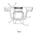
- FIG. 5is a cross-sectional side view of the assembled SI and AP components of FIG. 1 ;
- FIG. 6is a perspective top view of the SI and AP components of FIG. 1 ;
- FIG. 7is a top view of the SI and AP components of FIG. 1 with the AP component rotated to show it is rotatable about the center of the SI component;
- FIG. 8is a perspective view of the SI component of FIG. 1 ;
- FIG. 9is a cross-sectional side view of the SI component of FIG. 1 ;
- FIG. 10is a perspective view of the AP component of FIG. 1 ;
- FIG. 11is a side view of the AP component of FIG. 1 ;
- FIG. 12is a cross-sectional side view of the AP component of FIG. 1 ;
- FIG. 13is a partially exploded perspective view of the SI and AP components of FIG. 1 and a glenosphere;
- FIG. 14is a bottom perspective view of the glenosphere of FIG. 13 ;
- FIG. 15is an exploded perspective view of a glenoid vault system with an SI component, an AP component with an augment, an articulating component and screws;
- FIG. 16is an assembled perspective view of the glenoid vault system of FIG. 15 ;
- FIG. 17is a perspective view of the AP component of FIG. 15 ;
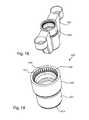
- FIG. 18is a perspective view of an assembled SI component of FIG. 1 or 15 and a cylindrical component;
- FIG. 19is a perspective view of the cylindrical component of FIG. 18 ;
- FIG. 20is a partially exploded perspective view of the SI component of FIG. 1 or 15 , the cylindrical component of FIG. 18 and an articulating component with augment;
- FIG. 21is an assembled side view the SI component of FIG. 1 or 15 , the cylindrical component of FIG. 18 and the articulating component with augment of FIG. 20 ;
- FIG. 22is a bottom perspective view of the articulating component with augment of FIG. 20 ;
- FIG. 23is a bottom perspective view of an articulating component with stepped augment
- FIG. 24is a partially exploded alternate embodiment of a glenoid vault system with a horizontal member, vertical member, screws, a hex component and an articulating component;
- FIG. 25is a cross sectional side view of the glenoid vault system of FIG. 24 with the horizontal member extending across the page;
- FIG. 26is a perspective view of the vertical and horizontal members of FIG. 24 ;
- FIG. 27is an exploded perspective view of the vertical and horizontal components of FIG. 24 ;
- FIG. 28is a perspective view of the vertical component of FIG. 24 ;
- FIG. 29is a top view of the vertical component of FIG. 24 ;
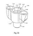
- FIG. 30is a perspective view of the horizontal component of FIG. 24 ;
- FIG. 31is a top view of the horizontal component of FIG. 24 ;
- FIG. 32is a cross sectional side view of the horizontal component of FIG. 24 ;
- FIG. 33is a perspective view of the vertical component of FIG. 24 and a cylindrical member
- FIG. 34is a perspective view of the vertical and horizontal component of FIG. 25 with an augment member
- FIG. 35is a perspective view of the augment member of FIG. 34 ;
- FIG. 36is a side view of the glenoid vault system of FIG. 24 with the augment of FIG. 35 ;
- FIG. 37is a perspective view of an alternate augment
- FIG. 38is a side view of the glenoid vault system of FIG. 24 with the augment of FIG. 37 ;
- FIG. 39is a perspective view of an alternate augment
- FIG. 40is a side view of the glenoid vault system of FIG. 24 with the augment of FIG. 39 ;
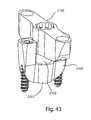
- FIG. 41is a perspective view of an alternate embodiment of an anchoring system for the glenoid vault with an alternate vertical member and horizontal member and screws;
- FIG. 42is a top view of the alternate embodiment anchoring system of FIG. 41 with the vertical component rotated to show it is rotatable about the center of the horizontal component;
- FIG. 43is a perspective view of the anchoring system of FIG. 41 with the vertical member slightly exploded from the horizontal member;
- FIG. 44is a perspective view of the horizontal member of FIG. 41 ;
- FIG. 45is a perspective view of the vertical member of FIG. 41 ;
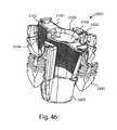
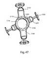
- FIG. 46is a perspective view of an alternate embodiment of an anchoring system for the glenoid vault with blade anchors
- FIG. 47is a top view of the anchoring system of FIG. 46 ;
- FIG. 48is a perspective view of the horizontal member of FIG. 46 ;
- FIG. 49is a perspective view of the vertical member of FIG. 46 ;
- FIG. 50is a perspective view of a sample blade anchor for use in the systems of FIGS. 46, 52 and 54 ;
- FIG. 51is a perspective view of an alternate embodiment of an anchor with bone wall filler
- FIG. 52is a perspective view of a one piece vertical member with built in anchors and slots to receive more anchors;
- FIG. 53is a top perspective view of the one piece vertical member of FIG. 50 with horizontal anchors in the slots;
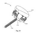
- FIG. 54is a perspective view of an alternate embodiment glenoid vault system with a vault, screw, anchors and glenoid;
- FIG. 55is an exploded perspective view of the system of FIG. 54 ;
- FIG. 56is a cross sectional view of the vault and screw of FIG. 54 ;
- FIG. 57is a bottom perspective view of the glenoid of the system of FIG. 54 ;
- FIG. 58is a bottom perspective view of a glenosphere that may be attached to the vault system of FIG. 54 in place of the glenoid.
- the present disclosureprovides systems, apparatus, and methods for shoulder replacement, repair and revision.
- the systems and methods described hereinmay improve shoulder prosthetics for use in shoulder arthoplasty and revision surgeries and provide stronger attachment of prosthetics to bone.
- Superiormeans toward the head. Inferior means away from the head. Anterior means toward the front. Posterior means toward the back. Medial means toward the midline, or plane of bilateral symmetry, of the body. Lateral means away from the midline of the body. Proximal means toward the trunk of the body. Distal means away from the trunk.
- a perspective viewillustrates a glenoid vault system 10 that may be implanted into a shoulder.
- the glenoid vault system 10includes an articulating component 20 , anchoring components with include a superior-inferior (SI) or vertical component 100 , an anterior-posterior (AP) or horizontal component 200 and anchors 300 which may be screws.
- SIsuperior-inferior
- APanterior-posterior
- anchors 300which may be screws.
- the system 10allows interaction of the different components with the articulating component 20 engaging the AP component 200 and the AP component engaging the SI component 100 .
- the screws 300may pass through different portions of the AP component 200 and the SI component 100 .
- the articulating component 20has a curvature shaped to mirror an anatomical shoulder with a semi-spherical or concave articulating surface 22 peripherally surrounded by a wall 24 .
- the articulating componentalso includes a bone-facing surface 26 facing the opposite direction as the articulating surface 22 and a post 28 extending from the bone-facing surface 26 in a substantially central location of the bone-facing surface 26 .
- the post 28may also extend substantially perpendicular to the articulating surface 22 .
- the bone facing surface 26may rest against the shoulder bone.
- the post 28may include a ring shaped cutout 30 toward the distal end of the post 28 and notches 32 toward the proximal end of the post 28 .
- the glenoid vault system 10assembles with the SI component 100 being embedded in the bone (not shown).
- the AP component 200may rotate about a portion of the SI component with at least a portion of the AP component 200 within the SI component 100 before the AP component 200 is secured to the bone.
- the post 28 of the articulating component 20may engage the AP component 200 with the ring shaped cutout 30 or a ring shaped protrusion with a complimentary seal or snap fit, or other locking means including a Morse taper (not shown) which may not require an engagement ring, on the AP component 200 .
- the systemis described in further detail herein.
- the SI component 100 and AP component 200interact through a body 102 , which may be a central ring, of the SI component 100 and a tubular boss 202 of the AP component 200 .
- the body 102may be a ring and the ring may be central to the SI component 100 ; however, the geometric component may be offset from the center as well and may be any shape including cylindrical or other polygonal shape.
- the tubular boss 202extends distally from a cylindrical wall 204 defining a hole 206 , wherein the hole may be a centralized or a central hole.
- the tubular boss 202may slidably engage the central ring 102 allowing the AP component 200 to rotate about the central ring 102 of the SI component 100 .
- the AP component 200may be secured to the SI component 100 through a Morse taper.
- the SI and AP components 100 , 200form a cruciate when they are engaged.
- a cruciatemeans a cross shape or X shape.
- the SI component 100may include a bore 103 , which may be a central bore, extending at least partially through the body or central ring 102 in a longitudinal direction and may extend entirely through the central ring 102 .
- the SI componentincludes a distal end 104 and may include two arms 106 , 108 extending from the central ring 102 .
- the arms 106 , 108include a proximal end 110 and a distal end 112 that is the same distal end 112 , 104 of the SI component 100 .
- Portions of the arms 106 , 108extend proximally from the central ring 102 giving the SI component 100 a V or U-shaped configuration for the SI component 100 .
- the extension of the arms 106 proximallymay be substantially parallel and substantially the same length, wherein the arms are coplanar; however the arms may differ in length slightly as well which may give the SI component 100 a J-shape, wherein the arms are not coplanar.
- the extension of the arms 106 , 108may be collinear and the arms 106 , 108 may prove to be mirror images if a cross section is taken of the SI component 100 .
- the portion of the arms 106 , 108 toward the central ring 102may cylindrically curve around the central ring 102 with the same degree of curvature as the central ring 102 .
- the body of the SI component 100may be longer than it is wide from a top view providing a narrow footprint when the SI component sits within the bone with the arms 106 , 108 narrower than the central ring 102 .
- the arm 106may include an opening or bore 114 defined by a wall 116 , which may be an arm ring, which may be cylindrical in shape, at the end of the arm 106 . Bores 114 may also be referred to as lateral passages.
- the arm ring 116may protrude from the arm 106 in substantially the same direction as the arm 106 extending from the central ring 102 .
- the opening 114may extend entirely through the arm ring 116 substantially parallel with the central bore 103 .
- the opening 114is substantially circular in cross section and configured to receive a screw 300 .
- the opening 114may include recesses, conical in shape, to guide the screw 300 into place in the SI component 100 as well as seat the screw 300 in its proper place.
- the opening 114may be a double conical shape with the narrowest point seated toward the middle of the opening 114 , the shape expanding outward toward either end of opening 114 , as best seen in FIG. 9 .
- the opening 114may slidably or threadably receive the screws 300 .
- the recesses in the openings 114may allow for the heads of the screws 300 to sit flush with a proximal surface 120 at the proximal end 110 of the arms 106 , 108 of the SI component 100 .
- the arm 108may include similar or identical features as arm 106 , but extending in the opposite direction from the central ring 102 .
- the SI component 100may be made from numerous different materials that include, but should not be limited to, titanium and alloys, cobalt-chrome and alloys, stainless steel, ceramic, tantalum, PEEK, PEAK, hydroxyapatite and biocompatible materials.
- the central ring 102includes a larger cylindrical receiver 122 for receiving the tubular boss 202 of the AP component 200 .
- the central ring 102also includes a central opening 118 distal the cylindrical receiver 122 .
- the central opening 118may be conical in shape with the wider portion of the central opening toward the distal end 104 .
- One screw 300may pass through the central bore 103 , the head of the screw engaging the SI component 100 and locking it to the bone.
- the screw 300may threadably or slidably engage the central bore 103 .
- a bonewherein the bone may be a scapula, may be properly prepared by placing a guidewire on the bone. The bone is then reamed and a primary hole is drilled, the primary hole is drilled at size to allow the central ring 102 of the SI component 100 to fit within the primary hole. Secondary holes or pilot are drilled, sized, and shaped to accept other portions of the SI component. A cutting or punch instrument may be used to connect or bridge the primary and secondary holes. The bone is then broached for the near net shape of the SI component 100 . An SI broach may be used as a trial implant. With the broach in the bone, or vault of the bone, the AP holes may be drilled to fit the exact size of the AP component 200 .
- the same steps for the preparation of the SI component 100are mimicked for the AP component 200 while the SI trial is in the bone, or vault of the bone.
- the AP and SI trialsare removed and replaced with the actual SI and AP components 100 , 200 , that can be secured to the bone using proper screws 300 or other anchors.
- the screws 300may through the central bore 103 and the head of the screw 300 engages the SI component 100 through the conical shaped opening, securing the SI component to the bone. Additional screws may pass through the openings 114 for greater security of the SI component 100 to the bone.
- the AP component 200may be further secured as well with screws that pass through holes 214 of the AP component 200
- the AP component 200may include the central cylindrical wall 204 defining the central hole 206 extending entirely through the AP component with the central hole 206 passing into the tubular boss 202 .
- the tube of the tubular boss 202may be an extension of the central hole 206 .
- the tubular boss 202may be circumferentially smaller than the cylindrical wall 204 defining the central hole 206 .
- At a proximal end 207 of the central hole 206 of the AP component 200may reside notches or grooves 209 that allow rotational orientation of the articulating component 20 and may serve as a keyed or complimentary fit with the articulating component 20 to prevent rotation of the articulating component 20 after engaging the AP component 200 .
- the notches or grooves 209may be cross sectionally rounded or squared or any other shape to prevent rotation of the articulating component 20 after engaging the AP component 200 .
- An alternate embodiment of an anti-rotation/rotational orientation featurewhich may take the place of the notches or grooves 209 may include splines (not shown) extending from a proximal surface 224 of either the AP or SI component 100 , 200 .
- the splinesmay engage crescent bosses (not shown) that extend from the bone facing surface 26 of the articulating component 20 .
- the crescent bossesmay include multiple holes for receiving the splines.
- First and second AP arms 208 , 210extend away from the central hole 206 at or toward the proximal end 207 of the AP component 200 .
- the AP arms 208 , 210may be collinear with the first AP arm 208 extending in an opposite direction as the second AP arm 210 .
- Each of the AP arms 208 , 210may be the same length; however, the AP arms 208 , 210 may differ in length as well depending on the patient anatomy and what bone is available to secure the AP component 200 to. Similar to the SI component arms 106 , 108 the AP arms 208 , 210 each have arm walls 212 , which may be AP arm rings.
- the AP arm rings 212may protrude from the arms 208 , 210 in substantially the same direction as the arms 208 , 210 extending from the cylindrical wall 204 .
- the AP arm rings 212include holes 214 extending entirely through the AP arm rings.
- the holes 214may also be referred to as AP lateral passages.
- the holes 214may be substantially cylindrical in shape, to allow for passage of the screws 300 to aid in securing the AP component 200 to the bone.
- One or more keels 216may extend distally from the AP arms toward a distal end 218 of the tubular boss 202 .
- the keels 216may be used for bone purchase.
- the keels 216may extend beyond the distal end 218 of the tubular boss keels 216 may cylindrically curve around the tubular boss 202 with the same degree of curvature as the tubular boss 202 .
- the keels 216may extend substantially parallel to one another creating a slot 220 between each one of the keels 216 and the tubular boss 202 .
- the slot 220receives the central ring 102 of the SI component 100 .
- the keels 216may provide rotational stops when the keels engage the arms 106 , 108 of the SI component 100 preventing any further rotations of the AP component 200 .
- the body of the AP component 200may be longer than it is wide providing a narrow footprint when the AP component 200 engages the SI component 100 and resides in the bone.
- an engagement ring 222is positioned on the central wall 204 within the central hole 206 of the AP component 100 .
- the engagement ring 222is positioned toward the proximal end of the AP component end but distal to the notches or grooves 209 .
- the engagement ringmay protrude out from the central wall 204 , extend toward the center of the central hole 206 , or it may be a cut out within the central wall 204 , extending away from the center of the central hole 206 .
- the engagement ring 222serves to engage and reversibly lock axial movement the ring shaped cutout 30 or protrusion of the post 28 of the articulating member 20 to the AP component 200 .
- the post 28 of the articulating component 20includes a complimentary fit with the engagement ring 222 whether it is a protrusive ring or cut out ring.
- the complimentary fit between the ring shaped cutout 30 and the engagement ring 222may be a snap fit or seal or any other means for reversibly locking the articulating component 20 to the AP component 200 , including a Morse taper (not shown) which may not require an engagement ring.
- the holes 214 in the arms 208 , 210may taper or recess from the proximal end 207 toward a distal end providing guidance for the screws and engagement with the screw heads.
- the holes 214may threadably or slidably receive the screws 300 and the recesses or tapers may allow the screw head to sit flush with a proximal surface 224 at the proximal end 207 of the AP component 200 .
- the AP component 200may be made from numerous different materials, which include, but should not be limited to, titanium and alloys, cobalt-chrome and alloys, stainless steel, ceramic, tantalum, hydroxyapatite and biocompatible materials.
- One method of implanting the system 10includes preparing the bone as Previously described and implanting the SI component 100 into the bone with appropriate screws 300 .
- the AP component 200may properly engage the SI component 100 with the tubular boss 202 slidably engaging the central ring 102 , the tubular boss 202 sliding within the central ring 102 .
- the AP component 200is carefully placed at a proper angle, which may be predetermined, within the best available bone to provide greater security. Screws 300 may pass through the holes 214 to secure the AP component 200 to the bone.
- the articulating component 20may engage the AP component 200 after the AP component 200 is properly placed and positioned within the SI component 100 and the bone.
- the order in which the components engage one anotheris not restrictive and a separate order may be established such as engaging the SI and AP component 100 , 200 prior to implanting into the bone.
- a glenosphere 60may replace or be used instead of an articulating component 20 .
- the glenosphere 60may be used for a reverse shoulder arthroplasty but may engage the AP component 200 in the same manner as the articulating component 20 .
- the glenosphere 60may be semi-spherical or domed and include an articulating surface 62 that may comprise the semi-spherical portion of the glenosphere 60 with a bone-facing surface 64 .
- the glenosphere 60may also include a metaglene component 66 on the bone facing surface 64 side of the glenosphere 60 .
- the metaglene component 66may be a separate piece that fits within a dome cutout 68 .
- the metaglene 66may be stoutly cylindrical.
- the dome cutout 68may be circular in cross section on the bone facing side of the semispherical portion of the glenosphere 60 .
- the metaglene 66engages the dome cutout 68 through a press or snap-fit sitting flush with the glenosphere bone facing surface 64 .
- the metaglene 66may also be a single piece with the glenosphere 60 .
- the metaglene 66may include metaglene holes 70 passing through the body of The metaglene 66 that may be used to pass screws through to fixate to the metaglene 66 to bone.
- the metaglene holes 70may also provide a place for securing an augment to the glenosphere 60 .
- a post 72extends away from the metaglene 66 in a similar fashion as the articulating component post 28 .
- the glenosphere post 72may include at least one step-down 74 as well as a post cutout 76 .
- the post cutout 76may engage the engagement ring 222 of the AP component 200 in a manner similar to or identical to the manner of the articulating component post 28 of the articulating component 20 .
- the glenosphere 60 and the articulating component 20may engage the AP component 200 without removal of either the AP component 200 or the SI component 100 of the glenoid vault system 10 . Revision surgery is done with greater ease because the components can be snapped in and out of the SI and AP anchors 100 , 200 without removal of any more bone.
- an alternate embodiment of a glenoid vault system 410includes an articulating member 420 , an AP component 500 with an augment, the SI component 100 and the anchors or screws 300 .
- the interaction between the different componentsis similar to the previous embodiment.
- the articulating member 420is substantially similar to the previous embodiment.
- the articulating member 420has a curvature shaped to mirror an anatomical shoulder with a semi-spherical or concave articulating surface 422 peripherally surrounded by a wall 424 .
- the articulating componentalso includes a bone-facing surface 426 facing the opposite direction as the articulating surface 422 and a post 428 extending from the bone-facing surface 426 in a substantially central location of the bone-facing surface 426 .
- the bone facing surface 426may rest against the scapula.
- the post 428may include a ring shaped cutout 430 toward the distal end of the post 428 and notches 432 toward the proximal end of the post 428 .
- this embodiment of the articulating member 420includes an augment 434 extending from the bone facing surface 426 separate from the post 428 and the augment 434 is not as long as the post 428 .
- the augment 434extends from only one side of the bone-facing surface 426 and the other portion of the bone facing surface 426 matches the curvature of the articulating surface 422 .
- the augment 434may match the curvature of the peripheral wall 424 and its curvature on the one side of the articulating member 420 .
- the augment 434interacts with a portion of the AP component 500 that will be discussed further herein.
- the augment 434is provided to replace an area where much of the bone has been removed.
- the AP component 500may include the central cylindrical wall 504 defining central hole 506 extending entirely through the AP component with the central hole 506 passing into the tubular boss 502 .
- the tube of the tubular boss 502may be an extension of the central hole 506 .
- the tubular boss 502may be circumferentially smaller than the cylindrical wall 504 defining the central hole 506 while the circumference of the central hole 506 may remain constant through from the cylindrical wall 504 to a distal end 510 of the tubular boss 502 .
- the central hole 506 of the AP component 500may reside notches or grooves 509 that may serve a complimentary fit with the notches 432 of the articulating component 420 to allow rotational orientation of the articulating component and prevent rotation of the articulating component 420 after engaging the AP component 500 .
- An AP augment 508extends away from the central hole 506 from the distal end 510 of the AP component 500 .
- the AP augment 508may extend 180° or more around the circumferential edge of the cylindrical wall 504 .
- a peripheral wall 514wraps around the AP augment 508 and may match the curvature of the articulating member 420 .
- the AP augment 508also include an articulating facing side 516 and a bone facing side 518 .
- the articulating facing side 516may include pockets 520 divided by a ridge 522 .
- the pockets 520receive and complimentary fit the augment 434 of the articulating member 420 .
- the pockets 520may match the curvature of the peripheral wall 514 of the AP augment 508 .
- each pocket 520may include an augment hole 524 to allow for passage of a screw.
- the augment hole 524may pass through the entire body of the AP augment 508 in substantially the same direction as the central hole 506 .
- the screwmay threadably or slidably pass through the augment hole 524 wherein the screw head may engage the augment hole 524 and secure the AP component 500 to the bone.
- the AP component 500may include the same or similar features as the previously described embodiment including the engagement ring 222 that engages the ring shaped cutout 430 of the articulating member 420 .
- the AP component 500also includes the grooves or notches 509 that interact with the notches 432 of the articulating member 420 in much the same manner as the previous embodiment to allow rotational orientation of the articulating component and prevent rotation of the articulating member 420 about the AP component 500 .
- a method of implanting this embodiment of the glenoid vault system 410is similar to that previously described herein substituting the alternate embodiment AP component 500 for the previous AP component 200 .
- a cylindrical component 600may include some of the similar features of the previous AP components 200 , 500 .
- the cylindrical component 600includes the same or similar features as the previously disclosed AP components 200 , 500 with the exclusion of arms and augments and simply includes the cylindrical portion itself.
- Cylindrical component 600includes a tubular boss 602 extending from a cylindrical wall 604 defining a central hole 606 .
- the tubular boss 602may be circumferentially smaller than the cylindrical wall 604 defining the central hole 606 while the circumference of the central hole 506 may remain constant through from a proximal end 608 of the cylindrical wall 604 to a distal end 610 of the tubular boss 602 .
- notches or grooves 612which may serve as a complimentary fit with the notches of the articulating members or components, or the glenosphere to allow rotational orientation of the articulating component and prevent rotation of the articulating member or component, or glenosphere after engaging the AP component 600 .
- the cylindrical component 600may also include the engagement ring 222 as previously disclosed for securing an articulating component or member or glenosphere, particularly the post portion of the articulating component, to the cylindrical component 600 .
- the security of the two partsmay come from a seal or snap fit, or other locking means including a Morse taper (not shown) which may not require an engagement ring, as previously described herein.
- an articulating component 720includes an augment 722 as part of the articulating component, essentially a one-piece articulating component with augment.
- a peripheral wall 724extends from an articulating surface 730 to the bone-facing surface 726 .
- the augment 722may be separate from a post 728 and extend from a bone facing side 726 separate from where the post 728 extends from the bone facing side 726 .
- the articulating component 720further includes notches 732 that interact or engage the grooves or notches 612 of the cylindrical component in much the same manner as the previous embodiment forming a complimentary fit preventing rotation of the articulating component 720 .
- the post 728may further include the ring shaped cutout 734 for locking the articulating component 720 to the cylindrical component 600 .
- the augment 722may also be rounded or smoothly tapered extending from the peripheral wall 724 .
- the augment 722may extend from the peripheral wall 724 toward a medial line or middle point of the articulating component 720 and wrap around the post 728 but not contacting the post 728 .
- the post 728may be greater in length than the augment 722 .
- the augment 722 of the articulating component 720is to replace that area of the shoulder where bone may be removed, as is the case with all the augment designs disclosed herein.
- an alternate embodiment of an articulating component 760may include an augment 767 with a step-down taper.
- the step-downsmay step down both peripherally and in a lateral direction from a middle point or medial line of the articulating component 760 .
- the remainder of the alternate embodimentmay be substantially similar as the previous articulating component 720 embodiment.
- FIGS. 24 and 25there is depicted an alternate embodiment of a glenoid vault system 1000 .
- the components in this embodimentare similar to the previous system 10 .
- An articulating component 1020is substantially similar to the previous embodiment articulating component 20 ; however the articulating component 1020 does not include notches to prevent rotation of the articulating component 1020 .
- a polygon, or keyed, component 1060that includes a cylindrical hole 1062 , is inserted onto or wraps around a post 1022 , which may be cylindrical in shape, of the articulating component 1020 .
- the polygon component 1060may be press fit onto the post.
- the polygon component 1060may be hexagonal in shape.
- the polygon component 1060engages a complimentary recess within an AP component 1200 , preventing rotation of the articulating component 1020 .
- the post 1022includes substantially the same feature of a cutout configured to interact with an engagement ring on the AP component 1200 to lock the post 1022 to the AP component 1200 .
- the lockmay be a snap fit, or seal 1024 , or other locking means including a Morse taper (not shown) which may not require an engagement ring.
- the glenoid vault system 1000also includes an SI component 1100 and AP component 1200 and anchors or screws 1300 similar to the previous system 10 .
- the features of these componentsdiffer slightly and will be described further herein.
- the interaction between the SI component 1100 and AP component 1200is substantially the same as the previous system 10 .
- a tubular boss 1202 of the AP componentmay slideably engage a central ring 1102 of the SI component, allowing the AP component to rotate within the central ring 1102 .
- the SI component 1100includes a central bore 1103 passing entirely through the central ring 1102 and arms 1106 , 1108 extending from the central ring 1102 .
- the arms 1106 , 1108extend in a wing-like manner from the central ring 1102 curvedly tapering from a proximal end 1110 toward a distal end 1112 .
- the armsinclude openings 1114 that may extend entirely through the arm to receive screws 1300 (not shown) in substantially the same manner as previously described in the previous embodiment.
- the arms 1106 , 1108may include tracks 1116 for receiving an augment (as depicted in FIGS. 34-38 ).
- the tracks 1116may be dovetail shaped and may be on either side of the arms 1106 , 1108 , on one arm or both arms.
- the tracks 1116may run partially or entirely from the proximal end 1110 to the distal end 1112 .
- the SI component 1100from a profile view, may be U-shaped.
- the AP component 1200includes the tubular boss 1202 and a body 1204 , with a central hole 1206 passing entirely through the center of the body 1204 and through the tubular boss 1202 .
- the tubular boss 1202may extend from the center of the body 1204 at a distal end 1218 of the AP component 1200 .
- the AP component 1200also includes AP arms 1208 , 1210 extending similarly to the arms of the SI component 1100 .
- the AP arms 1208 , 12010extend from the center of the body 1204 at the distal end 1218 toward a proximal end 1216 in a wing-like manner, curvedly tapering from the proximal end 1216 toward the distal end 1218 .
- the armsinclude holes 1214 that may extend entirely through the arm to receive screws 1300 in substantially the same manner as the previously embodiment.
- the AP component 1200further includes a polygon recess or polygon key 1220 toward the proximal end 1216 within the body 1204 of the AP component 1200 .
- the polygon recess 1220provides complimentary fit for the polygon component 1060 wherein the polygon component 1060 may, but is not required to, sit flush with the proximal end 1216 within the polygon recess 1220 .
- Within the central hole 1206is an engagement ring 1222 that is substantially similar to the previous embodiment and interacts in substantially the same way to form a snap fit or seal or other similar locking mechanism including a Morse taper (not shown) which may not require an engagement ring.
- a cylindrical component 1400 with features of the AP component 1200is shown, and is similar to the cylindrical component 600 .
- the elements of the body of the AP component 1400are substantially similar to component 600 , having a tubular boss (not shown but within the central bore of the SI component 1100 ), a central hole 1402 and a polygon recess 1404 .
- the cylindrical componentmay also include an engagement ring as previously described to lock the articulating component 1020 to the AP component 1400 .
- This embodimentlacks arms and may be better suited to receive augments like those depicted in FIGS. 34-38 .
- an augment 1500is shown with the SI component 1100 and the AP component 1200 .
- the augment 1500includes a straight edge 1502 with two dovetailed protrusions 1504 spaced apart from one another, perpendicular to the straight edge 1502 , and configured to slide in the tracks 1116 of the SI component 1100 .
- the straight edge 1502terminates on each end of the augment where two curved edges 1506 arch back toward a midline of the augment 1500 .
- a valley 1508may divide the augment into two mirror image sides wherein each side of the augment includes a pocket 1510 which may receive a partial augment from the articulating component 1020 similar to the partial augment of articulating component 420 or the one-piece augment articulating components 720 , 760 .
- the pockets 1510may include holes 1512 passing through the augment 1500 to allow for passage of screws 1300 to secure the augment 1500 to the bone.
- an augment 1600may include substantially the same features of the augment 1500 ; however, the augment 1600 may include tubular bosses 1602 extending in a direction away from the articulating component essentially extending the length of holes 1604 for receiving the screws 1300 .
- the screws 1300may secure the augment 1600 to the bone.
- an augment 1700includes a curved surface 1702 shaped to lie against a bone facing surface 1762 of an articulating component 1760 .
- the curvature of the curved surface 1702may match the curvature of the bone facing surface 1762 .
- Extending from the opposite side of the curved surface 1702 of the augment 1700is a saddle 1704 that straddles a horizontal or AP component 2200 .
- the augment 1700may include a centralized hole 1706 passing through the body of the augment 1700 as well as additional holes 1708 passing through the body of the augment 1700 to allow for passage of screws to secure the augment 1700 to the bone.
- FIGS. 40-43an alternate embodiment of a glenoid vault system 2000 is depicted with a vertical or SI member 2100 , a horizontal or AP member 2200 , screws 2300 and an articulating component 1750 .
- the augment 1700may or may not be present in this embodiment.
- This system 2000is similar to the previously disclosed systems 10 , 1000 with the exception that a portion of the vertical member 2100 fits in the horizontal member 2200 instead of vice versa. In this instance the horizontal member 2200 is embedded into the bone and then a portion of the vertical member 2100 slides into a portion of the horizontal member 2200 .
- the horizontal member 2200includes all of the same elements as previously described for a previously described AP component 200 with the exception that the features of the central rings 102 , 1102 of the previous embodiments are now found in the horizontal member 2200 instead of the vertical member 2100 .
- the horizontal member 2200is embedded in the bone in an anterior posterior direction first and then the vertical member 2100 is embedded in the bone in a generally superior inferior direction.
- the horizontal member 2200includes a central ring 2202 that is large enough to receive a tubular boss 2102 extending from the vertical member 2100 .
- the horizontal member 2200includes the central ring 2202 that defines a central bore 2204 that may pass partially or entirely through the central ring 2202 .
- a screw 1300may pass through the central bore 2204 to aid in securing the horizontal member 2200 to bone.
- Arms 2206 , 2208extend from the central ring 2202 rather abruptly in a proximal direction terminating at a proximal end 2210 .
- the arms 2206 , 2208may be somewhat longer from the proximal end to a distal end 2212 than previous embodiments of the SI components 100 , 1100 .
- the arms 2206 , 2208may each include a bore 2214 which extend the entire length of the arm from the proximal end 2210 to the distal end 2212 and are configured to receive screws 1300 .
- the bores 2214may surround a larger portion of the screws 1300 because of the greater length of the arms 2206 , 2208 in a proximal/distal direction.
- Toward the distal end 2212 of the arms 2206 , 2208 a portion of the arms 2208 , 2008 on the lateral sidemay be cut away to expose the threads of the screw 1300 to allow for greater security and fixation of the screws 1300 to the bone.
- Many features of the horizontal member 2200are similar to those of the previously disclosed SI components 100 , 1100 including the curvature of the arms toward the central ring 2204 matching the curvature of the central ring 2204 to allow the vertical member 2100 to rotate.
- the vertical member 2100is short, narrow and elongated.
- the vertical member 2100is stout from a proximal end 2104 to a distal end 2106 .
- the tubular boss 2102extends from the distal end and includes a portion of a central hole 2108 that may extend entirely from the proximal end 2104 to the distal end 2106 and through the entire length of the tubular boss 2102 .
- the vertical member 2100is elongated because of vertical member arms 2110 , 2112 extending outwardly in opposite directions from the central hole 2108 .
- the vertical member arms 2110 , 2112each include a hole 2114 to receive screws to secure the vertical member 2100 to the bone.
- the holes 2114are separate from the central hole 2108 .
- the walls within the central hole 2108 toward the proximal end 2104may include grooves or notches 2116 that may form a keyed fit or complimentary interaction with articulating component notches 1764 seen in FIG. 40 .
- These notches or grooves 2116allow rotational orientation of the articulating component and prevent rotation of the articulating member 1760 after it engages the vertical member 2100 .
- These notches or grooves 2166may be rounded or squared or any shape that may prevent rotation and have the complimentary fit on the articulating component 1760 .
- the vertical member 2100may also include an engagement ring (not shown) that is similar to the previous embodiment engagement ring 222 .
- the engagement ringprovides a reversible locking of the articulating component 1760 to the vertical member 2100 through a snap fit or seal, or other locking means including a Morse taper (not shown) which may not require an engagement ring, in substantially the same manner as previously disclosed.
- the method for inserting the vertical and horizontal members into the boneis substantially similar as previously described except with the bone may require anterior-posterior preparation first instead of superior-inferior preparation.
- the order of implantation and interaction between the componentscan be changed and is not meant to be restrictive.
- FIGS. 46-51an alternate embodiment of a glenoid vault system 3000 with a horizontal member 3200 and vertical member 3100 is depicted.
- the system 3000is substantially similar to the previous system 2000 with a few notable exceptions.
- Horizontal member tracks 3202are in place of the bores 2214 in the arms 2206 , 2208 of the horizontal member 2200 .
- vertical member tracks 3102are in place of the holes 2114 of the arms 2110 , 2112 of the vertical member 2100 .
- the tracks 3102 , 3202may be dovetailed to receive anchors 3300 , which may be blade anchors similar to those found in U.S. published patent application no.
- the anchor 3300may be a bone-augmenting anchor 3302 that may provide for alternate fixation by adding greater size to the blade portion 3304 .
- the blade portion 3304 of the bone-augmenting anchormay be rectangular or trapezoidal in cross sectional shape.
- the blade anchors 3300may be embedded or inserted into the bone in the manner as described in the incorporated patent application.
- the method for implantation using blade anchors 3300may be slightly different simply because the blade anchors may require little to no bone preparation for securing those anchors to the bone and is outlined in the published patent application referenced herein.
- the vertical member 3100also includes new Features such as roughened or interrupted surface geometry that may be circumferential ridges 3104 that may aid in preventing pull out of the vertical member 3000 . Ridges 3104 may be used in all the previous embodiments as well.
- the vertical member 3100also includes a wall 3106 cylindrically surrounding a central hole 3108 .
- the wall 3106includes at least two cutouts 3110 on opposing sides of the wall 3106 toward a proximal end.
- the cutouts 3110provide a keyed or complimentary fit with an articulating component (not shown) to allow rotational orientation of the articulating component and prevent rotation of the articulating component after engaging the vertical member 3100 .
- the shape, size and number of the cutoutsmay vary and may be similar to those previous described as notches or grooves herein.
- a single anchoring system 3400includes only a vertical member 3402 that is implantable in a shoulder in superior-inferior direction.
- the vertical memberincludes features substantially similar to the previous embodiment vertical member 3100 ; however the present embodiment does not interact with a horizontal member.
- This vertical member 3402includes a distal end 3404 , a proximal end 3406 , and a central hole 3408 defined by a cylindrical wall 3410 substantially the same as the previous embodiment vertical member 3100 with the same cutouts 3110 as previously described.
- the central hole 3408terminates just prior to a distal end 3404 and does not pass through the entire body of the vertical member 3402 .
- Arms 3412 , 3414extend from the cylindrical wall 3406 in opposite directions away from the central hole 3408 .
- the arms 3412 , 3414terminate with blade anchors 3300 integrally formed with the body of the vertical member 3400 .
- One or more tracks 3416may be integrally formed within the body of the vertical member 3402 and extend from the proximal end 3406 toward the distal end 3404 terminating just prior to the distal end.
- the tracks 3416may be dovetailed and are configured to receive anchors 3300 .
- the number of tracks 3416may vary and may extend from only one side of the arms 3412 , 3414 or both sides.
- An articulating membermay interact and engage the vertical member 3402 in much the same manner as any of the previous embodiment herein described.
- the system 4000includes a vault 4100 that may be pear-shaped, but may also be ovoid, spherical, cylindrical or many other shapes.
- the shape of the vault 4100may depend on the bone preparation and the patient anatomy.
- the systemalso includes an articulating component 4200 , a screw 4300 , which may be a scapular spine screw, blade anchors 4400 as previously described herein, and a locking nut 4500 .
- the vault 4100may comprise a circumferential wall 4102 defining the shape of the vault and encircling a central hole 4104 and an articulating void 4106 adjacent to and proximal the central hole 4104 .
- the central hole 4104may be cylindrical and may threadably or slidably receive the screw 4300 .
- a screw seat 4105(refer to FIG. 56 ) sits toward a distal end of the central hole 4104 and engages a head of the screw 4302 and allows the screw 4300 to pivot to secure the vault 4100 to the best bone.
- the locking nut 4500is threaded and short and threadably engages the central hole 4104 locking the screw 4300 in place and preventing back-out. The locking nut 4500 fits at least partially, if not entirely, within the central hole 4104 .
- the articulating void 4106provides a space for the articulating member 4200 to engage and lock to the vault 4100 .
- the articulating void 4106 defined by the wall 4102may have the same shape as the vault 4100 .
- the void 4106may taper, providing an overhang 4108 of the wall 4102 to provide a snap fit for engaging the articulating component 4200 .
- the wall 4102may also include an engagement ring similar to those embodiments previously described that protrudes toward the central hole 4104 into the void 4106 .
- Multiple tracks 4110may be embedded in the outside of the wall 4102 .
- the tracksmay be substantially similar as the tracks 3416 , 3102 previously described herein and interact with the blade anchors 4400 in substantially the same manner as previously described herein.
- the articulating component 4200may be similar to those embodiments previously described with the exception of the post.
- a post 4202extends from the bone facing side of the articulating component 4200 but may form a larger footprint from those posts previously disclosed.
- the post 4202may include a first locking mechanism 4204 and a second locking mechanism 4206 .
- the first locking mechanism 4204is a reverse taper that extends out from where the post initially protrudes from the bone facing side of the articulating component 4200 .
- the second locking mechanism 4206that comprises a shoulder 4208 to snap into the void 4106 below the overhang 4108 of the wall 4102 .
- the articulating glenosphere 4600shows a similar engagement feature as the articulating component 4200 and engages the vault 4100 in substantially the same manner as the articulating component 4200 .
- the articulating component 4200 and glenosphere 4600are reversibly locked to the vault so revision surgeries are easily accomplished without having to remove the vault 4100 .
- One method for implanting the vault system 4000is to prepare the bone for the vault 4100 and securing the vault to the bone with the screw 4300 . After securing the vault 4300 the locking nut 4500 locks the screw into place.
- the blade anchors 4400may insert into the bone before, during or after the screw 4300 is inserted or fixed.
- the articulating component 4200 or glenosphere 4600is then locked to the vault.
- the order in which the different components are securedis meant to be illustrative and not restrictive and the order may change within the scope of the system 4000 .
- any articulating component or glenospherewill interact with the vaults in such a manner to allow for easy attachment while maintaining a robust design.
- the engagementallows for interchangeability from an articulating component to a glenosphere for easy revision.
- the vertical member widthmay be less than 6 mm; the horizontal member width may be less than or equal to 5 mm; overall vault depth may be less than 20 mm; the central portion or central ring diameter may be less than 9 mm; the central hole or central bore may be used for a scapular spine screw; and the cross members/components length or anchor sizing can be varied.
Landscapes
- Health & Medical Sciences (AREA)
- Transplantation (AREA)
- Orthopedic Medicine & Surgery (AREA)
- Vascular Medicine (AREA)
- Oral & Maxillofacial Surgery (AREA)
- Engineering & Computer Science (AREA)
- Biomedical Technology (AREA)
- Heart & Thoracic Surgery (AREA)
- Cardiology (AREA)
- Life Sciences & Earth Sciences (AREA)
- Animal Behavior & Ethology (AREA)
- General Health & Medical Sciences (AREA)
- Public Health (AREA)
- Veterinary Medicine (AREA)
- Physical Education & Sports Medicine (AREA)
- Prostheses (AREA)
Abstract
Description
Claims (45)
Priority Applications (12)
| Application Number | Priority Date | Filing Date | Title |
|---|---|---|---|
| US13/360,459US9439768B2 (en) | 2011-12-08 | 2012-01-27 | Glenoid vault fixation |
| US13/367,165US8920508B2 (en) | 2011-12-08 | 2012-02-06 | Glenoid vault fixation |
| EP12705013.6AEP2787931B1 (en) | 2011-12-08 | 2012-02-06 | Glenoid vault fixation |
| AU2012321087AAU2012321087B2 (en) | 2011-12-08 | 2012-02-06 | Glenoid vault fixation |
| PCT/US2012/024035WO2013085552A1 (en) | 2011-12-08 | 2012-02-06 | Glenoid vault fixation |
| US13/708,799US9414927B2 (en) | 2011-12-08 | 2012-12-07 | Shoulder arthroplasty |
| EP12809439.8AEP2787932A1 (en) | 2011-12-08 | 2012-12-07 | Shoulder arthroplasty |
| AU2012321093AAU2012321093B2 (en) | 2011-12-08 | 2012-12-07 | Shoulder arthroplasty |
| PCT/US2012/068605WO2013086440A1 (en) | 2011-12-08 | 2012-12-07 | Shoulder arthroplasty |
| US14/561,885US20150094819A1 (en) | 2011-12-08 | 2014-12-05 | Glenoid vault fixation |
| AU2015205925AAU2015205925B2 (en) | 2011-12-08 | 2015-07-24 | Glenoid vault fixation |
| AU2015205931AAU2015205931B2 (en) | 2011-12-08 | 2015-07-24 | Shoulder arthroplasty |
Applications Claiming Priority (3)
| Application Number | Priority Date | Filing Date | Title |
|---|---|---|---|
| US201161568530P | 2011-12-08 | 2011-12-08 | |
| US13/360,459US9439768B2 (en) | 2011-12-08 | 2012-01-27 | Glenoid vault fixation |
| US13/367,165US8920508B2 (en) | 2011-12-08 | 2012-02-06 | Glenoid vault fixation |
Related Child Applications (1)
| Application Number | Title | Priority Date | Filing Date |
|---|---|---|---|
| US13/367,165Continuation-In-PartUS8920508B2 (en) | 2011-12-08 | 2012-02-06 | Glenoid vault fixation |
Publications (2)
| Publication Number | Publication Date |
|---|---|
| US20130150972A1 US20130150972A1 (en) | 2013-06-13 |
| US9439768B2true US9439768B2 (en) | 2016-09-13 |
Family
ID=48574953
Family Applications (3)
| Application Number | Title | Priority Date | Filing Date |
|---|---|---|---|
| US13/360,459Active2033-11-19US9439768B2 (en) | 2011-12-08 | 2012-01-27 | Glenoid vault fixation |
| US13/367,165ActiveUS8920508B2 (en) | 2011-12-08 | 2012-02-06 | Glenoid vault fixation |
| US14/561,885AbandonedUS20150094819A1 (en) | 2011-12-08 | 2014-12-05 | Glenoid vault fixation |
Family Applications After (2)
| Application Number | Title | Priority Date | Filing Date |
|---|---|---|---|
| US13/367,165ActiveUS8920508B2 (en) | 2011-12-08 | 2012-02-06 | Glenoid vault fixation |
| US14/561,885AbandonedUS20150094819A1 (en) | 2011-12-08 | 2014-12-05 | Glenoid vault fixation |
Country Status (3)
| Country | Link |
|---|---|
| US (3) | US9439768B2 (en) |
| AU (3) | AU2012321087B2 (en) |
| WO (1) | WO2013085552A1 (en) |
Cited By (4)
| Publication number | Priority date | Publication date | Assignee | Title |
|---|---|---|---|---|
| US11096800B2 (en)* | 2015-01-08 | 2021-08-24 | Medacta International Sa | Joint prosthesis with removal device |
| US11458019B2 (en) | 2019-06-25 | 2022-10-04 | Depuy Ireland Unlimited Company | Prosthetic implants including a frame for fixation to bone and related methods |
| US11752000B2 (en) | 2020-03-03 | 2023-09-12 | Howmedica Osteonics Corp. | Glenoid implant with additively manufactured fixation posts |
| US12268610B2 (en) | 2020-05-07 | 2025-04-08 | Howmedica Osteonics Corp. | Stemless metaphyseal humeral implant |
Families Citing this family (95)
| Publication number | Priority date | Publication date | Assignee | Title |
|---|---|---|---|---|
| US8778028B2 (en) | 2005-02-25 | 2014-07-15 | Shoulder Innovations, Inc. | Methods and devices for less invasive glenoid replacement |
| US20230080207A1 (en) | 2005-02-25 | 2023-03-16 | Shoulder Innovations, Inc. | Methods and devices for less invasive glenoid replacement |
| WO2010121250A1 (en) | 2009-04-17 | 2010-10-21 | Arthrosurface Incorporated | Glenoid resurfacing system and method |
| US10945743B2 (en) | 2009-04-17 | 2021-03-16 | Arthrosurface Incorporated | Glenoid repair system and methods of use thereof |
| FR2955247B1 (en) | 2010-01-21 | 2013-04-26 | Tornier Sa | GLENOIDAL COMPONENT OF SHOULDER PROSTHESIS |
| USD685474S1 (en) | 2010-07-06 | 2013-07-02 | Tornier, Inc. | Prosthesis anchor |
| FR2967046A1 (en) | 2010-11-10 | 2012-05-11 | Tornier Sa | ORTHOPEDIC BONE PREPARATION MACHINE, ESPECIALLY GLENOIDIAN PREPARATION |
| FR2971144A1 (en) | 2011-02-08 | 2012-08-10 | Tornier Sa | GLENOIDAL IMPLANT FOR SHOULDER PROSTHESIS AND SURGICAL KIT |
| US9668873B2 (en) | 2013-03-08 | 2017-06-06 | Biomet Manufacturing, Llc | Modular glenoid base plate with augments |
| EP3046513A1 (en)* | 2013-09-18 | 2016-07-27 | Zimmer, Inc. | Adaptor for modular joint prostheses |
| US10433969B2 (en) | 2013-12-30 | 2019-10-08 | United Orthopedic Corp. | Arthroplasty implants and methods for orienting joint prosthesis |
| US9956083B2 (en) | 2013-12-30 | 2018-05-01 | Deltoid, Llc | Instruments and techniques for orienting prosthesis components for joint prostheses |
| US9962266B2 (en) | 2015-09-11 | 2018-05-08 | Deltoid, Llc | Arthroplasty components |
| WO2015103090A1 (en) | 2014-01-03 | 2015-07-09 | Tornier, Inc. | Reverse shoulder systems |
| US10456264B2 (en)* | 2014-01-24 | 2019-10-29 | Tornier, Inc. | Humeral implant anchor system |
| US12023253B2 (en) | 2014-01-24 | 2024-07-02 | Howmedica Osteonics Corp. | Humeral implant anchor system |
| JP2017513818A (en) | 2014-03-15 | 2017-06-01 | ノバルティス アーゲー | Treatment of cancer using chimeric antigen receptors |
| EP2939638B1 (en)* | 2014-04-30 | 2018-04-11 | Zimmer GmbH | A set for connecting a prosthetic assembly of an artificial joint to a bone |
| US9681960B2 (en) | 2014-05-16 | 2017-06-20 | Howmedica Osteonics Corp. | Guides for fracture system |
| US10575968B2 (en) | 2014-05-16 | 2020-03-03 | Howmedica Osteonics Corp. | Guides for fracture system |
| US11234826B2 (en)* | 2014-06-30 | 2022-02-01 | Howmedica Osteonics Corp. | Augmented glenoid components and devices for implanting the same |
| JP2017528433A (en) | 2014-07-21 | 2017-09-28 | ノバルティス アーゲー | Low immunoenhancing dose of mTOR inhibitor and CAR combination |
| US10492926B1 (en) | 2014-09-04 | 2019-12-03 | Shoulder Innovations, Inc. | Alignment guide for humeral or femoral stem replacement prostheses |
| ES2891332T3 (en) | 2014-09-17 | 2022-01-27 | Novartis Ag | Targeting cytotoxic cells with chimeric receptors for adoptive immunotherapy |
| WO2016090034A2 (en) | 2014-12-03 | 2016-06-09 | Novartis Ag | Methods for b cell preconditioning in car therapy |
| US11161907B2 (en) | 2015-02-02 | 2021-11-02 | Novartis Ag | Car-expressing cells against multiple tumor antigens and uses thereof |
| US20160270922A1 (en)* | 2015-03-19 | 2016-09-22 | Limacorporate S.P.A. | Glenoid Anchor for a Shoulder Joint Prosthesis |
| EP3270828B1 (en)* | 2015-03-19 | 2019-12-25 | Limacorporate SPA | Improved glenoid anchor for a shoulder joint prosthesis |
| US9510952B2 (en)* | 2015-04-03 | 2016-12-06 | Biomet Maufacturing, LLC | Glenoid trial and implant assembly for reverse total shoulder arthroplasty and method of use |
| EP3286211A1 (en) | 2015-04-23 | 2018-02-28 | Novartis AG | Treatment of cancer using chimeric antigen receptor and protein kinase a blocker |
| US10722374B2 (en) | 2015-05-05 | 2020-07-28 | Tornier, Inc. | Convertible glenoid implant |
| US11667691B2 (en) | 2015-08-07 | 2023-06-06 | Novartis Ag | Treatment of cancer using chimeric CD3 receptor proteins |
| CN108603200B (en) | 2015-11-23 | 2022-08-19 | 诺华股份有限公司 | Optimized lentiviral transfer vectors and uses thereof |
| EP3397756B1 (en) | 2015-12-30 | 2023-03-08 | Novartis AG | Immune effector cell therapies with enhanced efficacy |
| BR112018067679A2 (en) | 2016-03-04 | 2019-01-15 | Novartis Ag | cells expressing multiple chimeric antigen receptor (car) molecules and their use |
| WO2017165683A1 (en) | 2016-03-23 | 2017-09-28 | Novartis Ag | Cell secreted minibodies and uses thereof |
| US10463499B2 (en) | 2016-03-25 | 2019-11-05 | Tornier, Inc. | Stemless shoulder implant with fixation components |
| AU2017250304B2 (en) | 2016-04-15 | 2023-08-17 | Novartis Ag | Compositions and methods for selective protein expression |
| EP3260087B1 (en) | 2016-06-24 | 2019-08-07 | Tornier | Set for a glenoid implant |
| US11129724B2 (en) | 2016-07-28 | 2021-09-28 | Howmedica Osteonics Corp. | Stemless prosthesis anchor component |
| US20190161542A1 (en) | 2016-08-01 | 2019-05-30 | Novartis Ag | Treatment of cancer using a chimeric antigen receptor in combination with an inhibitor of a pro-m2 macrophage molecule |
| WO2018111340A1 (en) | 2016-12-16 | 2018-06-21 | Novartis Ag | Methods for determining potency and proliferative function of chimeric antigen receptor (car)-t cells |
| KR20250080917A (en) | 2017-01-19 | 2025-06-05 | 앙코르 메디컬, 엘.피.(디/비/에이 디제이오 서지컬) | Shoulder implant components |
| EP3574005B1 (en) | 2017-01-26 | 2021-12-15 | Novartis AG | Cd28 compositions and methods for chimeric antigen receptor therapy |
| JP2020506700A (en) | 2017-01-31 | 2020-03-05 | ノバルティス アーゲー | Cancer treatment using multispecific chimeric T cell receptor protein |
| WO2018160731A1 (en) | 2017-02-28 | 2018-09-07 | Novartis Ag | Shp inhibitor compositions and uses for chimeric antigen receptor therapy |
| EP4520302A3 (en)* | 2017-04-14 | 2025-04-16 | Shoulder Innovations, Inc. | Total shoulder prosthesis having inset glenoid implant convertible from anatomic to reverse |
| WO2018229715A1 (en) | 2017-06-16 | 2018-12-20 | Novartis Ag | Compositions comprising anti-cd32b antibodies and methods of use thereof |
| EP3644906B1 (en)* | 2017-06-29 | 2022-02-23 | Encore Medical, L.P. (D/B/A DJO Surgical) | Glenosphere with inserts for augmented fixation |
| MX2020003194A (en) | 2017-09-25 | 2020-12-09 | Howmedica Osteonics Corp | Patient specific stemless prosthesis anchor components. |
| WO2019079104A2 (en) | 2017-10-16 | 2019-04-25 | Imascap Sas | Shoulder implants and methods of use and assembly |
| MX2020004013A (en) | 2017-10-18 | 2021-01-08 | Novartis Ag | Compositions and methods for selective protein degradation. |
| US20200370012A1 (en) | 2017-10-25 | 2020-11-26 | Novartis Ag | Methods of making chimeric antigen receptor-expressing cells |
| WO2019081983A1 (en) | 2017-10-25 | 2019-05-02 | Novartis Ag | Antibodies targeting cd32b and methods of use thereof |
| US20210179709A1 (en) | 2017-10-31 | 2021-06-17 | Novartis Ag | Anti-car compositions and methods |
| US11399948B2 (en) | 2017-12-11 | 2022-08-02 | Howmedica Osteonics Corp. | Stemless prosthesis anchor components and kits |
| US11813166B2 (en)* | 2018-03-05 | 2023-11-14 | Synthes Gmbh | Trial radial head implant |
| US11129719B2 (en) | 2018-03-05 | 2021-09-28 | Synthes Gmbh | Trial radial head implant |
| WO2019210153A1 (en) | 2018-04-27 | 2019-10-31 | Novartis Ag | Car t cell therapies with enhanced efficacy |
| US12138172B2 (en) | 2018-04-30 | 2024-11-12 | Shoulder Innovations, Inc. | Inset/onlay glenoid, porous coated convertible glenoid, and humeral heads with textured undersides |
| WO2019213282A1 (en) | 2018-05-01 | 2019-11-07 | Novartis Ag | Biomarkers for evaluating car-t cells to predict clinical outcome |
| US20210213063A1 (en) | 2018-05-25 | 2021-07-15 | Novartis Ag | Combination therapy with chimeric antigen receptor (car) therapies |
| US20210123075A1 (en) | 2018-06-08 | 2021-04-29 | Novartis Ag | Compositions and methods for immunooncology |
| AR116109A1 (en) | 2018-07-10 | 2021-03-31 | Novartis Ag | DERIVATIVES OF 3- (5-AMINO-1-OXOISOINDOLIN-2-IL) PIPERIDINE-2,6-DIONA AND USES OF THE SAME |
| US10813769B2 (en) | 2018-07-24 | 2020-10-27 | DePuy Synthes Products, Inc. | Baseplate of a modular shoulder joint prosthesis and related methods for implanting the same |
| EP4257090A3 (en) | 2018-10-02 | 2023-12-13 | Howmedica Osteonics Corp. | Shoulder prosthesis components and assemblies |
| AU2019402189B2 (en) | 2018-12-20 | 2023-04-13 | Novartis Ag | Dosing regimen and pharmaceutical combination comprising 3-(1-oxoisoindolin-2-yl)piperidine-2,6-dione derivatives |
| EP4406516A3 (en)* | 2019-01-28 | 2024-08-07 | Encore Medical, L.P. (D/B/A Djo Surgical) | Glenoid implant |
| JP7483732B2 (en) | 2019-02-15 | 2024-05-15 | ノバルティス アーゲー | 3-(1-oxo-5-(piperidin-4-yl)isoindolin-2-yl)piperidine-2,6-dione derivatives and uses thereof |
| CA3123519A1 (en) | 2019-02-15 | 2020-08-20 | Novartis Ag | Substituted 3-(1-oxoisoindolin-2-yl)piperidine-2,6-dione derivatives and uses thereof |
| AU2020237088B2 (en)* | 2019-03-11 | 2025-09-04 | Shoulder Innovations, Inc. | Total reverse shoulder systems and methods |
| WO2020186099A1 (en) | 2019-03-12 | 2020-09-17 | Arthrosurface Incorporated | Humeral and glenoid articular surface implant systems and methods |
| USD977643S1 (en) | 2019-03-12 | 2023-02-07 | Shoulder Innovations, Inc. | Humeral stem implant |
| EP3959320A1 (en) | 2019-04-24 | 2022-03-02 | Novartis AG | Compositions and methods for selective protein degradation |
| EP3958796B1 (en)* | 2019-04-25 | 2024-02-14 | Encore Medical, L.P. (D/B/A DJO Surgical) | Glenoid implant |
| JP7257546B2 (en) | 2019-05-13 | 2023-04-13 | ハウメディカ オステオニクス コーポレイション | Glenoid baseplate and implant assembly |
| AU2020204539B2 (en)* | 2019-07-12 | 2024-10-31 | Howmedica Osteonics Corp. | Augmented glenoid design |
| US11666449B2 (en) | 2019-07-30 | 2023-06-06 | Howmedica Osteonics Corp. | Keeled glenoid implant |
| EP3982848A1 (en) | 2019-08-09 | 2022-04-20 | Howmedica Osteonics Corp. | Apparatuses and methods for implanting glenoid prostheses |
| US11406505B2 (en)* | 2019-08-20 | 2022-08-09 | Steven C. Chudik | Glenoid implant with replaceable articulating portion |
| EP4527357A3 (en) | 2019-10-01 | 2025-06-04 | Howmedica Osteonics Corporation | Shoulder prosthesis components and assemblies |
| US20230056470A1 (en) | 2019-12-20 | 2023-02-23 | Novartis Ag | Uses of anti-tgf-beta antibodies and checkpoint inhibitors for the treatment of proliferative diseases |
| US20230076768A1 (en) | 2020-01-14 | 2023-03-09 | Synthekine, Inc. | IL2 Orthologs and Methods of Use |
| CA3185455A1 (en) | 2020-06-11 | 2021-12-16 | Novartis Ag | Zbtb32 inhibitors and uses thereof |
| BR112022026202A2 (en) | 2020-06-23 | 2023-01-17 | Novartis Ag | DOSAGE REGIMEN COMPRISING 3-(1-OXOISOINDOLIN-2-IL)PIPERIDINE-2,6-DIONE DERIVATIVES |
| CN116134027B (en) | 2020-08-03 | 2025-01-24 | 诺华股份有限公司 | Heteroaryl substituted 3-(1-oxoisoindolin-2-yl)piperidine-2,6-dione derivatives and uses thereof |
| US11213422B1 (en) | 2021-02-23 | 2022-01-04 | Bluexthermal, Inc. | Wearable heat transfer devices and associated systems and methods |
| TW202304979A (en) | 2021-04-07 | 2023-02-01 | 瑞士商諾華公司 | USES OF ANTI-TGFβ ANTIBODIES AND OTHER THERAPEUTIC AGENTS FOR THE TREATMENT OF PROLIFERATIVE DISEASES |
| TW202309294A (en) | 2021-04-27 | 2023-03-01 | 瑞士商諾華公司 | Viral vector production system |
| JP2025501314A (en) | 2022-01-04 | 2025-01-17 | ブルーエックスサーマル, インコーポレイテッド | Ocular Area Heat Transfer Devices and Associated Systems - Patent application |
| FR3134309B1 (en)* | 2022-04-08 | 2024-05-10 | Fx Solutions | Implant mainly made of ceramic and assembly with gripping and placement device |
| WO2023214325A1 (en) | 2022-05-05 | 2023-11-09 | Novartis Ag | Pyrazolopyrimidine derivatives and uses thereof as tet2 inhibitors |
| EP4608983A1 (en) | 2022-10-26 | 2025-09-03 | Novartis AG | Lentiviral formulations |
| TW202500126A (en) | 2023-05-24 | 2025-01-01 | 美商金橘生物科技公司 | Heterocyclic compounds and uses thereof |
| CN118021489B (en)* | 2024-04-11 | 2024-07-05 | 北京爱康宜诚医疗器材有限公司 | A cartilage prosthesis |
Citations (86)
| Publication number | Priority date | Publication date | Assignee | Title |
|---|---|---|---|---|
| US1105105A (en) | 1912-02-10 | 1914-07-28 | William O'n Sherman | Surgical appliance. |
| US2580821A (en) | 1950-10-21 | 1952-01-01 | Nicola Toufick | Spring impactor bone plate |
| US2780223A (en) | 1955-05-17 | 1957-02-05 | Paul B Haggland | Fracture plate |
| US3593709A (en) | 1968-10-28 | 1971-07-20 | William X Halloran | Angular compression plate for bone fractures |
| US4364382A (en) | 1979-08-23 | 1982-12-21 | Ulrich Mennen | Internal fixation device for bone fractures |
| US4429690A (en) | 1980-09-15 | 1984-02-07 | Cise Centro Informazioni Studi Esperienze Spa | Plate for broken bone fixation |
| DE3630276A1 (en) | 1986-09-05 | 1988-03-17 | Gernot Dr Med Felmet | Cementlessly implantable self-tensioning acetabular cup |
| EP0339530A2 (en) | 1988-04-26 | 1989-11-02 | S + G Implants Gmbh | Endoprosthesis for a joint |
| US5047058A (en) | 1988-04-08 | 1991-09-10 | Smith & Nephew Richards, Inc. | System of inserts for the tibial component of a knee prosthesis |
| WO1993009733A1 (en) | 1991-11-18 | 1993-05-27 | Depuy Inc. | Modular prosthesis |
| US5387241A (en) | 1994-01-28 | 1995-02-07 | Zimmer, Inc. | Ribbed augment for a prosthetic implant |
| US5487741A (en) | 1992-11-16 | 1996-01-30 | Taguchi Medical Co., Ltd. | Bone plate |
| US5702447A (en) | 1995-11-30 | 1997-12-30 | Tornier S.A. | Device for the attachment of a glenoid prosthesis of the shoulder blade |
| US5755800A (en) | 1996-12-23 | 1998-05-26 | Johnson & Johnson Professional, Inc. | Modular joint prosthesis augmentation system |
| US5766255A (en) | 1996-12-23 | 1998-06-16 | Johnson & Johnson Professional, Inc. | Modular joint prosthesis stabilization and augmentation system |
| US5984969A (en) | 1995-06-01 | 1999-11-16 | Johnson & Johnson Professional, Inc. | Joint prosthesis augmentation system |
| US6005018A (en) | 1995-06-01 | 1999-12-21 | Johnson & Johnson Professional, Inc. | Augmentation device for joint prosthesis |
| US6093188A (en) | 1997-11-10 | 2000-07-25 | Murray; William M. | Adjustable bone fixation plate |
| US6200321B1 (en) | 1998-09-10 | 2001-03-13 | Hand Innovations, Inc. | Fracture fixation system |
| US6228119B1 (en) | 1998-06-09 | 2001-05-08 | Depuy Orthopaedics, Inc. | Modular glenoid assembly |
| US6364881B1 (en) | 1997-07-30 | 2002-04-02 | Interpore Cross International | Longitudinally adjustable bone plates and method for use thereof |
| US6406495B1 (en) | 1998-12-22 | 2002-06-18 | Sulzer Orthopedics Ltd. | Glenoid prosthesis and a modular system with glenoid prostheses |
| US6699289B2 (en) | 2001-12-31 | 2004-03-02 | Depuy Orthopaedics, Inc. | Augmented glenoid component having an interrupted surface and associated method for securing the augmented glenoid component to a glenoid surface of a scapula |
| US20040162619A1 (en) | 2001-08-27 | 2004-08-19 | Zimmer Technology, Inc. | Tibial augments for use with knee joint prostheses, method of implanting the tibial augment, and associated tools |
| FR2855743A1 (en) | 2003-06-06 | 2004-12-10 | Biotechni | Acetabulum implant cup insert for articular prosthesis e.g. hip prosthesis, has metallic shell with lever for avoiding extraction of polyethylene filling, and bosses and depressions for avoiding rotation of filling |
| EP1488764A1 (en) | 2003-04-30 | 2004-12-22 | LIMA Lto SpA | Inverse prosthesis for the shoulder joint |
| US20050049709A1 (en) | 2003-08-25 | 2005-03-03 | Alain Tornier | Glenoid component of a shoulder prosthesis and complete shoulder prosthesis incorporating such a component |
| US20050060039A1 (en) | 2003-09-11 | 2005-03-17 | Jean-Maxwell Cyprien | Shoulder glenoid prosthesis with method and tools for implanting it |
| US20050192578A1 (en) | 2004-02-26 | 2005-09-01 | Horst Steven P. | Bone plates with locking apertures |
| US6953478B2 (en) | 1999-12-23 | 2005-10-11 | Depuy France | Shoulder prosthesis assembly |
| US20050261775A1 (en) | 2004-05-19 | 2005-11-24 | Zimmer Gmbh | Glenoid anchor |
| US20050278030A1 (en) | 2004-06-15 | 2005-12-15 | Tornier | Glenoidal component, set of such components and shoulder prosthesis incorporating such a glenoidal component |
| US20060074430A1 (en) | 2004-09-27 | 2006-04-06 | Deffenbaugh Daren L | Instrument for preparing an implant support surface and associated method |
| EP1656910A1 (en) | 2004-11-10 | 2006-05-17 | LIMA Lto SpA | Inverse prosthesis for the articulation of the shoulder |
| US20060200248A1 (en) | 2005-03-03 | 2006-09-07 | Laurent Beguin | Prosthesis for the glenoid cavity of the scapula |
| US20060235407A1 (en) | 2001-11-09 | 2006-10-19 | Wang Robert C | Apparatus and methods for bone fracture reduction and fixation |
| US20070021838A1 (en) | 2005-07-22 | 2007-01-25 | Dugas Jeffrey R | Site specific minimally invasive joint implants |
| US20070038302A1 (en) | 2005-08-15 | 2007-02-15 | Biomet Manufacturing Corp. | Method and apparatus for the preparation of an inlaid glenoid |
| US20070055380A1 (en) | 2005-09-08 | 2007-03-08 | Biomet Manufacturing Corp | Method and apparatus for a glenoid prosthesis |
| US7204854B2 (en) | 2002-08-15 | 2007-04-17 | Arthrex, Inc. | Metal back prosthetic glenoid component with cemented pegs and hollow metal cage screw |
| EP1782764A2 (en) | 2005-11-03 | 2007-05-09 | LIMA Lto SpA | Attachment element for a prosthesis for the articulation of the shoulder |
| US20070142917A1 (en) | 2005-10-26 | 2007-06-21 | Roche Christopher P | Apparatus and method to obtain bone fixation |
| US7235106B2 (en) | 2002-12-20 | 2007-06-26 | Depuy Products, Inc. | Modular hip stems and associated method of trialing |
| US20070156246A1 (en) | 2003-08-29 | 2007-07-05 | Meswania Jayantilal M | Shoulder joint prosthetic system |
| US20070179624A1 (en) | 2006-02-02 | 2007-08-02 | Biomet Manufacturing Corp | Method and apparatus for performing a shoulder implant procedure |
| US20070225817A1 (en) | 2006-03-21 | 2007-09-27 | Reubelt Leo M | Glenoid component with improved fixation stability |
| US20070244563A1 (en) | 2006-03-23 | 2007-10-18 | Roche Chistopher P | Reverse shoulder prosthesis |
| US20070260321A1 (en) | 2006-05-02 | 2007-11-08 | Stchur Robert P | Conically-shaped glenoid implant with a prosthetic glenoid insert used in total shoulder arthroplasty and method |
| US20070270855A1 (en) | 2006-04-06 | 2007-11-22 | Lotus Medical, Llc | Active compression to facilitate healing of bones |
| DE102006041551A1 (en) | 2006-05-22 | 2007-11-29 | Mathys Ag Bettlach | shoulder prosthesis |
| US20080015589A1 (en) | 2006-06-16 | 2008-01-17 | Hack Bradford H | Bone plate with dynamic compression |
| US7329284B2 (en) | 2002-09-27 | 2008-02-12 | Depuy Products, Inc. | Concave resurfacing prosthesis |
| WO2008040408A1 (en) | 2006-09-29 | 2008-04-10 | Aesculap Ag & Co. Kg | Augmentation component for bone implants |
| US20080208348A1 (en) | 2005-02-11 | 2008-08-28 | Wolfgang Fitz | Apparatus and Method for Shoulder Arthroplasty |
| US20080243191A1 (en) | 2001-10-18 | 2008-10-02 | Fx Devices, Llc | Adjustable bone plate fixation system and metho |
| US7445638B2 (en) | 2005-03-03 | 2008-11-04 | Biomet France | Humeral implant for shoulder prosthesis |
| US20090149961A1 (en) | 2006-05-22 | 2009-06-11 | Mathys Ag Bettlach | Shoulder Prosthesis having a Protrusion on the Base Plate |
| WO2009092830A1 (en) | 2008-01-22 | 2009-07-30 | Penas Garcia Javier | Internal dynamic fastening device applicable to the osseous repair of fractures |
| US20090192621A1 (en) | 2003-10-08 | 2009-07-30 | Biomet Manufacturing Corp. | Shoulder Implant Assembly |
| WO2009100310A1 (en) | 2008-02-06 | 2009-08-13 | Raymond Raven Iii | Subcondylar fracture fixation plate system for tubular bones of the hand |
| US7604665B2 (en) | 2006-09-20 | 2009-10-20 | Depuy Products, Inc. | Glenoid component for shoulder arthroplasty |
| US20090281630A1 (en) | 2006-06-28 | 2009-11-12 | Trois S Ortho | Shoulder prosthesis and set of instruments for the implantation thereof |
| US20090292364A1 (en) | 2008-05-21 | 2009-11-26 | Linares Medical Devices, Llc | Shoulder implant with first and second composite sub-assemblies and improved mounting anchors for establishing a secure joint |
| US20100069966A1 (en) | 2008-09-15 | 2010-03-18 | Alfredo Castaneda | Bone Plate System for Hand Fractures and Other Small Bones |
| US20100114326A1 (en) | 2008-10-30 | 2010-05-06 | Biomet Manufacturing Corp. | Modular implant for joint prosthesis |
| US20100125336A1 (en) | 2007-01-18 | 2010-05-20 | The University Of Newcastle Upon Tyne | Reverse shoulder prosthesis |
| US20100129138A1 (en) | 2008-11-26 | 2010-05-27 | Lariviere Donald G | Captive bolt mechanism and process for structural assembly of planar components |
| US20100161065A1 (en) | 2008-12-23 | 2010-06-24 | Depuy Products, Inc. | Shoulder Prosthesis with Vault-Filling Structure having Bone-Sparing Configuration |
| US20100161066A1 (en) | 2008-12-23 | 2010-06-24 | Depuy Products, Inc. | Shoulder Prosthesis having Augmented Metaglene Component for Use in Rotator Cuff Deficient Shoulder |
| US7753959B2 (en) | 2006-03-20 | 2010-07-13 | Biomet Manufacturing Corp. | Modular center pegged glenoid |
| US20100217328A1 (en) | 2009-02-24 | 2010-08-26 | Osteomed L.P. | Multiple Bone Fusion Plate |
| US20100217399A1 (en) | 2009-02-22 | 2010-08-26 | Groh Gordon I | Base plate system for shoulder arthroplasty and method of using the same |
| US20100222886A1 (en) | 2006-01-20 | 2010-09-02 | Zimmer Technology, Inc. | Shoulder arthroplasty system |
| US20100228352A1 (en) | 2009-03-05 | 2010-09-09 | Tomier, Inc. | Glenoid implant anchor post |
| US20100274359A1 (en) | 2009-04-22 | 2010-10-28 | Yann Brunnarius | Joint prosthesis attachment system, device and method |
| US7892287B2 (en) | 2004-09-27 | 2011-02-22 | Depuy Products, Inc. | Glenoid augment and associated method |
| US7896886B2 (en) | 2005-01-28 | 2011-03-01 | Depuy Products, Inc. | Nail plate and implantation jig therefor |
| US20110060372A1 (en) | 2004-01-08 | 2011-03-10 | David Mark Allison | Bone fixing device |
| US7922769B2 (en) | 2004-09-27 | 2011-04-12 | Depuy Products, Inc. | Modular glenoid prosthesis and associated method |
| US20110106266A1 (en) | 2008-04-28 | 2011-05-05 | Smith & Nephew Orthopaedics Ag | Scapular component of a shoulder joint prosthesis |
| US20110112651A1 (en) | 2001-08-27 | 2011-05-12 | Zimmer, Inc. | Femoral augments for use with knee joint prosthesis |
| US20110137424A1 (en) | 2009-12-08 | 2011-06-09 | Depuy Products, Inc. | Shoulder Prosthesis Assembly having Glenoid Rim Replacement Structure |
| US20110152946A1 (en) | 2009-11-23 | 2011-06-23 | Synthes Usa, Llc | Flexible maxillo-mandibular fixation device |
| US8007538B2 (en) | 2005-02-25 | 2011-08-30 | Shoulder Innovations, Llc | Shoulder implant for glenoid replacement |
| US8048165B2 (en) | 2007-03-07 | 2011-11-01 | Biomet Manufacturing Corp. | Method and apparatus for removing a bearing |
| US20130090695A1 (en) | 2011-09-30 | 2013-04-11 | Acute Innovations, Llc | Bone fixation system with opposed mounting portions |
Family Cites Families (1)
| Publication number | Priority date | Publication date | Assignee | Title |
|---|---|---|---|---|
| US8349015B2 (en) | 2009-02-11 | 2013-01-08 | Howmedica Osteonics Corp. | Intervertebral implant with integrated fixation |
- 2012
- 2012-01-27USUS13/360,459patent/US9439768B2/enactiveActive
- 2012-02-06AUAU2012321087Apatent/AU2012321087B2/ennot_activeCeased
- 2012-02-06USUS13/367,165patent/US8920508B2/enactiveActive
- 2012-02-06WOPCT/US2012/024035patent/WO2013085552A1/enactiveApplication Filing
- 2014
- 2014-12-05USUS14/561,885patent/US20150094819A1/ennot_activeAbandoned
- 2015
- 2015-07-24AUAU2015205931Apatent/AU2015205931B2/ennot_activeCeased
- 2015-07-24AUAU2015205925Apatent/AU2015205925B2/ennot_activeCeased
Patent Citations (99)
| Publication number | Priority date | Publication date | Assignee | Title |
|---|---|---|---|---|
| US1105105A (en) | 1912-02-10 | 1914-07-28 | William O'n Sherman | Surgical appliance. |
| US2580821A (en) | 1950-10-21 | 1952-01-01 | Nicola Toufick | Spring impactor bone plate |
| US2780223A (en) | 1955-05-17 | 1957-02-05 | Paul B Haggland | Fracture plate |
| US3593709A (en) | 1968-10-28 | 1971-07-20 | William X Halloran | Angular compression plate for bone fractures |
| US4364382A (en) | 1979-08-23 | 1982-12-21 | Ulrich Mennen | Internal fixation device for bone fractures |
| US4429690A (en) | 1980-09-15 | 1984-02-07 | Cise Centro Informazioni Studi Esperienze Spa | Plate for broken bone fixation |
| DE3630276A1 (en) | 1986-09-05 | 1988-03-17 | Gernot Dr Med Felmet | Cementlessly implantable self-tensioning acetabular cup |
| US5047058A (en) | 1988-04-08 | 1991-09-10 | Smith & Nephew Richards, Inc. | System of inserts for the tibial component of a knee prosthesis |
| EP0339530A2 (en) | 1988-04-26 | 1989-11-02 | S + G Implants Gmbh | Endoprosthesis for a joint |
| WO1993009733A1 (en) | 1991-11-18 | 1993-05-27 | Depuy Inc. | Modular prosthesis |
| US5487741A (en) | 1992-11-16 | 1996-01-30 | Taguchi Medical Co., Ltd. | Bone plate |
| US5387241A (en) | 1994-01-28 | 1995-02-07 | Zimmer, Inc. | Ribbed augment for a prosthetic implant |
| US5984969A (en) | 1995-06-01 | 1999-11-16 | Johnson & Johnson Professional, Inc. | Joint prosthesis augmentation system |
| US6005018A (en) | 1995-06-01 | 1999-12-21 | Johnson & Johnson Professional, Inc. | Augmentation device for joint prosthesis |
| US5702447A (en) | 1995-11-30 | 1997-12-30 | Tornier S.A. | Device for the attachment of a glenoid prosthesis of the shoulder blade |
| US5755800A (en) | 1996-12-23 | 1998-05-26 | Johnson & Johnson Professional, Inc. | Modular joint prosthesis augmentation system |
| US5766255A (en) | 1996-12-23 | 1998-06-16 | Johnson & Johnson Professional, Inc. | Modular joint prosthesis stabilization and augmentation system |
| US6364881B1 (en) | 1997-07-30 | 2002-04-02 | Interpore Cross International | Longitudinally adjustable bone plates and method for use thereof |
| US6093188A (en) | 1997-11-10 | 2000-07-25 | Murray; William M. | Adjustable bone fixation plate |
| US6228119B1 (en) | 1998-06-09 | 2001-05-08 | Depuy Orthopaedics, Inc. | Modular glenoid assembly |
| US6514287B2 (en) | 1998-06-09 | 2003-02-04 | Depuy Orthopaedics, Inc. | Modular glenoid assembly having bearing insert |
| US6273892B1 (en) | 1998-09-10 | 2001-08-14 | Hand Innovations, Inc. | Fracture fixation system |
| US6200321B1 (en) | 1998-09-10 | 2001-03-13 | Hand Innovations, Inc. | Fracture fixation system |
| US6406495B1 (en) | 1998-12-22 | 2002-06-18 | Sulzer Orthopedics Ltd. | Glenoid prosthesis and a modular system with glenoid prostheses |
| US7611539B2 (en) | 1999-12-23 | 2009-11-03 | Depuy France | Shoulder prosthesis assembly |
| US6953478B2 (en) | 1999-12-23 | 2005-10-11 | Depuy France | Shoulder prosthesis assembly |
| US20040162619A1 (en) | 2001-08-27 | 2004-08-19 | Zimmer Technology, Inc. | Tibial augments for use with knee joint prostheses, method of implanting the tibial augment, and associated tools |
| US20110112651A1 (en) | 2001-08-27 | 2011-05-12 | Zimmer, Inc. | Femoral augments for use with knee joint prosthesis |
| US20080243191A1 (en) | 2001-10-18 | 2008-10-02 | Fx Devices, Llc | Adjustable bone plate fixation system and metho |
| US20060235407A1 (en) | 2001-11-09 | 2006-10-19 | Wang Robert C | Apparatus and methods for bone fracture reduction and fixation |
| US6699289B2 (en) | 2001-12-31 | 2004-03-02 | Depuy Orthopaedics, Inc. | Augmented glenoid component having an interrupted surface and associated method for securing the augmented glenoid component to a glenoid surface of a scapula |
| US7204854B2 (en) | 2002-08-15 | 2007-04-17 | Arthrex, Inc. | Metal back prosthetic glenoid component with cemented pegs and hollow metal cage screw |
| US20080109000A1 (en) | 2002-09-27 | 2008-05-08 | Depuy Products, Inc. | Tamp for concave resurfacing prosthesis |
| US20100070044A1 (en) | 2002-09-27 | 2010-03-18 | Depuy Products, Inc. | Concave Resurfacing Prosthesis |
| US7329284B2 (en) | 2002-09-27 | 2008-02-12 | Depuy Products, Inc. | Concave resurfacing prosthesis |
| US7235106B2 (en) | 2002-12-20 | 2007-06-26 | Depuy Products, Inc. | Modular hip stems and associated method of trialing |
| EP1488764A1 (en) | 2003-04-30 | 2004-12-22 | LIMA Lto SpA | Inverse prosthesis for the shoulder joint |
| US7169184B2 (en) | 2003-04-30 | 2007-01-30 | Lima Lto Spa | Inverse prosthesis for the articulation of the shoulder |
| FR2855743A1 (en) | 2003-06-06 | 2004-12-10 | Biotechni | Acetabulum implant cup insert for articular prosthesis e.g. hip prosthesis, has metallic shell with lever for avoiding extraction of polyethylene filling, and bosses and depressions for avoiding rotation of filling |
| US20060276905A1 (en) | 2003-06-06 | 2006-12-07 | Biotechni | Insert for a cotyloid implant cup for a joint prosthesis, cotyloid implant and joint prosthesis |
| US20050049709A1 (en) | 2003-08-25 | 2005-03-03 | Alain Tornier | Glenoid component of a shoulder prosthesis and complete shoulder prosthesis incorporating such a component |
| US20070156246A1 (en) | 2003-08-29 | 2007-07-05 | Meswania Jayantilal M | Shoulder joint prosthetic system |
| US20050060039A1 (en) | 2003-09-11 | 2005-03-17 | Jean-Maxwell Cyprien | Shoulder glenoid prosthesis with method and tools for implanting it |
| US20090192621A1 (en) | 2003-10-08 | 2009-07-30 | Biomet Manufacturing Corp. | Shoulder Implant Assembly |
| US20110060372A1 (en) | 2004-01-08 | 2011-03-10 | David Mark Allison | Bone fixing device |
| US20050192578A1 (en) | 2004-02-26 | 2005-09-01 | Horst Steven P. | Bone plates with locking apertures |
| US20050261775A1 (en) | 2004-05-19 | 2005-11-24 | Zimmer Gmbh | Glenoid anchor |
| EP1607067A1 (en) | 2004-06-15 | 2005-12-21 | Tornier | Glenoid component, set of such elements and shoulder prosthesis comprising such a glenoid component |
| US20050278030A1 (en) | 2004-06-15 | 2005-12-15 | Tornier | Glenoidal component, set of such components and shoulder prosthesis incorporating such a glenoidal component |
| US20060074430A1 (en) | 2004-09-27 | 2006-04-06 | Deffenbaugh Daren L | Instrument for preparing an implant support surface and associated method |
| US7892287B2 (en) | 2004-09-27 | 2011-02-22 | Depuy Products, Inc. | Glenoid augment and associated method |
| US7922769B2 (en) | 2004-09-27 | 2011-04-12 | Depuy Products, Inc. | Modular glenoid prosthesis and associated method |
| US20110144758A1 (en) | 2004-09-27 | 2011-06-16 | Daren Lloyd Deffenbaugh | Glenoid augment and associated method |
| EP1656910A1 (en) | 2004-11-10 | 2006-05-17 | LIMA Lto SpA | Inverse prosthesis for the articulation of the shoulder |
| EP1980221A1 (en) | 2004-11-10 | 2008-10-15 | LIMA - LTO SpA | Inverse prosthesis for the articulation of the shoulder |
| US7896886B2 (en) | 2005-01-28 | 2011-03-01 | Depuy Products, Inc. | Nail plate and implantation jig therefor |
| US20080208348A1 (en) | 2005-02-11 | 2008-08-28 | Wolfgang Fitz | Apparatus and Method for Shoulder Arthroplasty |
| US8007538B2 (en) | 2005-02-25 | 2011-08-30 | Shoulder Innovations, Llc | Shoulder implant for glenoid replacement |
| US7445638B2 (en) | 2005-03-03 | 2008-11-04 | Biomet France | Humeral implant for shoulder prosthesis |
| US20060200248A1 (en) | 2005-03-03 | 2006-09-07 | Laurent Beguin | Prosthesis for the glenoid cavity of the scapula |
| US20070021838A1 (en) | 2005-07-22 | 2007-01-25 | Dugas Jeffrey R | Site specific minimally invasive joint implants |
| US20070038302A1 (en) | 2005-08-15 | 2007-02-15 | Biomet Manufacturing Corp. | Method and apparatus for the preparation of an inlaid glenoid |
| US20070055380A1 (en) | 2005-09-08 | 2007-03-08 | Biomet Manufacturing Corp | Method and apparatus for a glenoid prosthesis |
| US20070142917A1 (en) | 2005-10-26 | 2007-06-21 | Roche Christopher P | Apparatus and method to obtain bone fixation |
| EP1782764A2 (en) | 2005-11-03 | 2007-05-09 | LIMA Lto SpA | Attachment element for a prosthesis for the articulation of the shoulder |
| US7608109B2 (en) | 2005-11-03 | 2009-10-27 | Lima Lto Spa | Attachment element for a prosthesis for the articulation of the shoulder |
| US20100222886A1 (en) | 2006-01-20 | 2010-09-02 | Zimmer Technology, Inc. | Shoulder arthroplasty system |
| US20070179624A1 (en) | 2006-02-02 | 2007-08-02 | Biomet Manufacturing Corp | Method and apparatus for performing a shoulder implant procedure |
| US7753959B2 (en) | 2006-03-20 | 2010-07-13 | Biomet Manufacturing Corp. | Modular center pegged glenoid |
| US20070225817A1 (en) | 2006-03-21 | 2007-09-27 | Reubelt Leo M | Glenoid component with improved fixation stability |
| US20070244563A1 (en) | 2006-03-23 | 2007-10-18 | Roche Chistopher P | Reverse shoulder prosthesis |
| US20070270855A1 (en) | 2006-04-06 | 2007-11-22 | Lotus Medical, Llc | Active compression to facilitate healing of bones |
| US20070260321A1 (en) | 2006-05-02 | 2007-11-08 | Stchur Robert P | Conically-shaped glenoid implant with a prosthetic glenoid insert used in total shoulder arthroplasty and method |
| WO2007134691A1 (en) | 2006-05-22 | 2007-11-29 | Mathys Ag Bettlach | Shoulder prosthesis |
| US20090164021A1 (en) | 2006-05-22 | 2009-06-25 | Mathys Ag Bettlach | Shoulder Prosthesis |
| US20090149961A1 (en) | 2006-05-22 | 2009-06-11 | Mathys Ag Bettlach | Shoulder Prosthesis having a Protrusion on the Base Plate |
| DE102006041551A1 (en) | 2006-05-22 | 2007-11-29 | Mathys Ag Bettlach | shoulder prosthesis |
| US20080015589A1 (en) | 2006-06-16 | 2008-01-17 | Hack Bradford H | Bone plate with dynamic compression |
| US20090281630A1 (en) | 2006-06-28 | 2009-11-12 | Trois S Ortho | Shoulder prosthesis and set of instruments for the implantation thereof |
| US7604665B2 (en) | 2006-09-20 | 2009-10-20 | Depuy Products, Inc. | Glenoid component for shoulder arthroplasty |
| WO2008040408A1 (en) | 2006-09-29 | 2008-04-10 | Aesculap Ag & Co. Kg | Augmentation component for bone implants |
| US20100125336A1 (en) | 2007-01-18 | 2010-05-20 | The University Of Newcastle Upon Tyne | Reverse shoulder prosthesis |
| US8048165B2 (en) | 2007-03-07 | 2011-11-01 | Biomet Manufacturing Corp. | Method and apparatus for removing a bearing |
| WO2009092830A1 (en) | 2008-01-22 | 2009-07-30 | Penas Garcia Javier | Internal dynamic fastening device applicable to the osseous repair of fractures |
| WO2009100310A1 (en) | 2008-02-06 | 2009-08-13 | Raymond Raven Iii | Subcondylar fracture fixation plate system for tubular bones of the hand |
| US20110106266A1 (en) | 2008-04-28 | 2011-05-05 | Smith & Nephew Orthopaedics Ag | Scapular component of a shoulder joint prosthesis |
| US20090292364A1 (en) | 2008-05-21 | 2009-11-26 | Linares Medical Devices, Llc | Shoulder implant with first and second composite sub-assemblies and improved mounting anchors for establishing a secure joint |
| US20100069966A1 (en) | 2008-09-15 | 2010-03-18 | Alfredo Castaneda | Bone Plate System for Hand Fractures and Other Small Bones |
| US20100114326A1 (en) | 2008-10-30 | 2010-05-06 | Biomet Manufacturing Corp. | Modular implant for joint prosthesis |
| US20100129138A1 (en) | 2008-11-26 | 2010-05-27 | Lariviere Donald G | Captive bolt mechanism and process for structural assembly of planar components |
| US20100161066A1 (en) | 2008-12-23 | 2010-06-24 | Depuy Products, Inc. | Shoulder Prosthesis having Augmented Metaglene Component for Use in Rotator Cuff Deficient Shoulder |
| US20100161065A1 (en) | 2008-12-23 | 2010-06-24 | Depuy Products, Inc. | Shoulder Prosthesis with Vault-Filling Structure having Bone-Sparing Configuration |
| US20100217399A1 (en) | 2009-02-22 | 2010-08-26 | Groh Gordon I | Base plate system for shoulder arthroplasty and method of using the same |
| US20100217328A1 (en) | 2009-02-24 | 2010-08-26 | Osteomed L.P. | Multiple Bone Fusion Plate |
| US20100228352A1 (en) | 2009-03-05 | 2010-09-09 | Tomier, Inc. | Glenoid implant anchor post |
| US20100274359A1 (en) | 2009-04-22 | 2010-10-28 | Yann Brunnarius | Joint prosthesis attachment system, device and method |
| US20110152946A1 (en) | 2009-11-23 | 2011-06-23 | Synthes Usa, Llc | Flexible maxillo-mandibular fixation device |
| US20110137424A1 (en) | 2009-12-08 | 2011-06-09 | Depuy Products, Inc. | Shoulder Prosthesis Assembly having Glenoid Rim Replacement Structure |
| US20130090695A1 (en) | 2011-09-30 | 2013-04-11 | Acute Innovations, Llc | Bone fixation system with opposed mounting portions |
Non-Patent Citations (12)
| Title |
|---|
| Fucentese, Sandro; Total shoulder Arthroplasty with an Uncemented Soft-Metal-Backed Glenoid Component, Journal of shoulder elbow Surgery (2010) 19, 624-631. |
| International Preliminary Report on Patentability and Written Opinion for International Application No. PCT/US2012/024035, dated Jun. 10, 2014 (6 pages). |
| International Preliminary Report on Patentability and Written Opinion for International Application No. PCT/US2012/068605, dated Jun. 10, 2014 (6 pages). |
| International Search Report for International Application No. PCT/US2012/024035, dated Aug. 7, 2012 (2 pages). |
| International Search Report for International Application No. PCT/US2012/068605, dated Mar. 20, 2013 (3 pages). |
| Jones, Geary C.; In-Vitro Evaluation of ta Polyurethane Compliant LA, Proc. IMechE vol. 224 Part H: J. Engineering in Medicine (2010) pp. 551-563. |
| Kasten, P.; Mid-Term Survivorship Analysis of a shoulder Replacement with a Keeled Glenoid and a Modern Cementing Technique, Journal of Bone and Joint Surgery (BR) Mar. 2010 vol. 92-B, No. 387-392. |
| Patent Examination Report No. 1 for Australian Application No. 2012321087, dated Mar. 21, 2014 (3 pages). |
| Patent Examination Report No. 1 for Australian Application No. 2012321093, dated Feb. 26, 2014 (3 pages). |
| Patent Examination Report No. 2 for Australian Application No. 2012321093, dated Apr. 11, 2015 (3 pages). |
| Sharma, Gulshan B.; Effect of Glenoid Prosthesis Design on Glenoid Bone Remodeling: Adaptive Finite Element based Simulation. Journal of Biomechanics 43(2010) 1653-1659. |
| Throckmorton, Thomas W.; Pegged Versus Keeled Glenoid Components in Total Shoulder Arthroplasty, Journal of Shoulder and Elbow Surgery (2010) 19, 726-733. |
Cited By (4)
| Publication number | Priority date | Publication date | Assignee | Title |
|---|---|---|---|---|
| US11096800B2 (en)* | 2015-01-08 | 2021-08-24 | Medacta International Sa | Joint prosthesis with removal device |
| US11458019B2 (en) | 2019-06-25 | 2022-10-04 | Depuy Ireland Unlimited Company | Prosthetic implants including a frame for fixation to bone and related methods |
| US11752000B2 (en) | 2020-03-03 | 2023-09-12 | Howmedica Osteonics Corp. | Glenoid implant with additively manufactured fixation posts |
| US12268610B2 (en) | 2020-05-07 | 2025-04-08 | Howmedica Osteonics Corp. | Stemless metaphyseal humeral implant |
Also Published As
| Publication number | Publication date |
|---|---|
| AU2012321087A1 (en) | 2013-06-27 |
| AU2015205931A1 (en) | 2015-08-20 |
| US20130150972A1 (en) | 2013-06-13 |
| AU2015205931B2 (en) | 2017-02-02 |
| US20130150974A1 (en) | 2013-06-13 |
| US20150094819A1 (en) | 2015-04-02 |
| AU2015205925B2 (en) | 2015-09-10 |
| AU2015205925A1 (en) | 2015-08-20 |
| AU2012321087B2 (en) | 2015-05-07 |
| WO2013085552A1 (en) | 2013-06-13 |
| US8920508B2 (en) | 2014-12-30 |
Similar Documents
| Publication | Publication Date | Title |
|---|---|---|
| US9439768B2 (en) | Glenoid vault fixation | |
| US9414927B2 (en) | Shoulder arthroplasty | |
| US12336912B2 (en) | Implants, systems and methods of using the same | |
| US9248023B2 (en) | Iliac canal prosthesis | |
| US11458019B2 (en) | Prosthetic implants including a frame for fixation to bone and related methods | |
| EP2484315B1 (en) | Minimally invasive total hip replacement | |
| EP3053547B1 (en) | Improved hip prosthesis | |
| AU2012321093B2 (en) | Shoulder arthroplasty | |
| US12167972B2 (en) | Tibial tray inserter | |
| EP2787931B1 (en) | Glenoid vault fixation | |
| EP2662056B1 (en) | Rotatable reverse metaglene assembly | |
| WO2024218066A1 (en) | Genoid implant and method of installing the same during an orthopaedic shoulder procedure | |
| HK1227276B (en) | Improved hip prosthesis | |
| HK1227276A1 (en) | Improved hip prosthesis |
Legal Events
| Date | Code | Title | Description |
|---|---|---|---|
| AS | Assignment | Owner name:CLEVELAND CLINIC FOUNDATION, OHIO Free format text:ASSIGNMENT OF ASSIGNORS INTEREST;ASSIGNOR:WILLIAMS, GERALD, DR.;REEL/FRAME:028310/0103 Effective date:20120321 Owner name:MEDICINELODGE, INC. DBA IMDS CO-INNOVATION, UTAH Free format text:ASSIGNMENT OF ASSIGNORS INTEREST;ASSIGNORS:KOKA, DINESH;HOLLIS, MICHAEL CHAD;REEL/FRAME:028310/0033 Effective date:20120411 Owner name:CLEVELAND CLINIC FOUNDATION, OHIO Free format text:ASSIGNMENT OF ASSIGNORS INTEREST;ASSIGNOR:IANNOTTI, JOSEPH, DR.;REEL/FRAME:028310/0176 Effective date:20120403 Owner name:CLEVELAND CLINIC FOUNDATION, OHIO Free format text:ASSIGNMENT OF ASSIGNORS INTEREST;ASSIGNOR:MEDICINELODGE, INC. DBA IMDS CO-INNOVATION;REEL/FRAME:028310/0223 Effective date:20120604 | |
| AS | Assignment | Owner name:IMDS CORPORATION, UTAH Free format text:ASSIGNMENT OF ASSIGNORS INTEREST;ASSIGNOR:CLEVELAND CLINIC FOUNDATION;REEL/FRAME:030168/0532 Effective date:20130329 | |
| FEPP | Fee payment procedure | Free format text:PAYOR NUMBER ASSIGNED (ORIGINAL EVENT CODE: ASPN); ENTITY STATUS OF PATENT OWNER: LARGE ENTITY | |
| AS | Assignment | Owner name:IMDS CORPORATION, UTAH Free format text:CHANGE OF NAME;ASSIGNOR:MEDICINELODGE, INC. DBA IMDS CO-INNOVATION;REEL/FRAME:038528/0112 Effective date:20120501 Owner name:IMDS LLC, UTAH Free format text:CHANGE OF NAME;ASSIGNOR:IMDS CORPORATION;REEL/FRAME:038528/0098 Effective date:20130901 | |
| STCF | Information on status: patent grant | Free format text:PATENTED CASE | |
| MAFP | Maintenance fee payment | Free format text:PAYMENT OF MAINTENANCE FEE, 4TH YEAR, LARGE ENTITY (ORIGINAL EVENT CODE: M1551); ENTITY STATUS OF PATENT OWNER: LARGE ENTITY Year of fee payment:4 | |
| MAFP | Maintenance fee payment | Free format text:PAYMENT OF MAINTENANCE FEE, 8TH YEAR, LARGE ENTITY (ORIGINAL EVENT CODE: M1552); ENTITY STATUS OF PATENT OWNER: LARGE ENTITY Year of fee payment:8 |