US9439760B2 - Stentless support structure - Google Patents
Stentless support structureDownload PDFInfo
- Publication number
- US9439760B2 US9439760B2US14/635,951US201514635951AUS9439760B2US 9439760 B2US9439760 B2US 9439760B2US 201514635951 AUS201514635951 AUS 201514635951AUS 9439760 B2US9439760 B2US 9439760B2
- Authority
- US
- United States
- Prior art keywords
- support structure
- configuration
- stentless support
- valve
- tubular structure
- Prior art date
- Legal status (The legal status is an assumption and is not a legal conclusion. Google has not performed a legal analysis and makes no representation as to the accuracy of the status listed.)
- Expired - Fee Related
Links
- 239000000835fiberSubstances0.000claimsdescription2
- 238000004904shorteningMethods0.000claims1
- 229910001000nickel titaniumInorganic materials0.000abstractdescription7
- HLXZNVUGXRDIFK-UHFFFAOYSA-Nnickel titaniumChemical compound[Ti].[Ti].[Ti].[Ti].[Ti].[Ti].[Ti].[Ti].[Ti].[Ti].[Ti].[Ni].[Ni].[Ni].[Ni].[Ni].[Ni].[Ni].[Ni].[Ni].[Ni].[Ni].[Ni].[Ni].[Ni]HLXZNVUGXRDIFK-UHFFFAOYSA-N0.000abstractdescription7
- 239000013013elastic materialSubstances0.000abstractdescription2
- 238000011065in-situ storageMethods0.000abstractdescription2
- 239000012781shape memory materialSubstances0.000abstractdescription2
- 239000000463materialSubstances0.000description9
- 238000000034methodMethods0.000description7
- 238000013459approachMethods0.000description6
- 210000005166vasculatureAnatomy0.000description6
- 238000001356surgical procedureMethods0.000description4
- 210000001519tissueAnatomy0.000description4
- 230000017531blood circulationEffects0.000description3
- 208000014674injuryDiseases0.000description3
- 229910001285shape-memory alloyInorganic materials0.000description3
- 230000008733traumaEffects0.000description3
- 208000031481Pathologic ConstrictionDiseases0.000description2
- 230000006870functionEffects0.000description2
- 238000002513implantationMethods0.000description2
- 230000008569processEffects0.000description2
- 238000011084recoveryMethods0.000description2
- 239000010935stainless steelSubstances0.000description2
- 229910001220stainless steelInorganic materials0.000description2
- 230000036262stenosisEffects0.000description2
- 208000037804stenosisDiseases0.000description2
- 208000037260Atherosclerotic PlaqueDiseases0.000description1
- 208000032750Device leakageDiseases0.000description1
- 206010019280Heart failuresDiseases0.000description1
- 206010067171RegurgitationDiseases0.000description1
- 208000007536ThrombosisDiseases0.000description1
- 229910045601alloyInorganic materials0.000description1
- 239000000956alloySubstances0.000description1
- 210000001367arteryAnatomy0.000description1
- 230000008901benefitEffects0.000description1
- 239000008280bloodSubstances0.000description1
- 210000004369bloodAnatomy0.000description1
- 238000009954braidingMethods0.000description1
- 230000002612cardiopulmonary effectEffects0.000description1
- 238000013130cardiovascular surgeryMethods0.000description1
- 210000000748cardiovascular systemAnatomy0.000description1
- 238000010276constructionMethods0.000description1
- 201000010099diseaseDiseases0.000description1
- 208000037265diseases, disorders, signs and symptomsDiseases0.000description1
- 230000005489elastic deformationEffects0.000description1
- 230000003073embolic effectEffects0.000description1
- 239000004744fabricSubstances0.000description1
- 210000001105femoral arteryAnatomy0.000description1
- 230000004927fusionEffects0.000description1
- 210000002216heartAnatomy0.000description1
- 210000003709heart valveAnatomy0.000description1
- 210000001308heart ventricleAnatomy0.000description1
- 238000009998heat settingMethods0.000description1
- 238000010438heat treatmentMethods0.000description1
- 238000012977invasive surgical procedureMethods0.000description1
- 230000002262irrigationEffects0.000description1
- 238000003973irrigationMethods0.000description1
- 238000004519manufacturing processMethods0.000description1
- 230000007246mechanismEffects0.000description1
- 229910052751metalInorganic materials0.000description1
- 239000002184metalSubstances0.000description1
- 150000002739metalsChemical class0.000description1
- 238000012986modificationMethods0.000description1
- 230000004048modificationEffects0.000description1
- 210000004165myocardiumAnatomy0.000description1
- RVTZCBVAJQQJTK-UHFFFAOYSA-Noxygen(2-);zirconium(4+)Chemical compound[O-2].[O-2].[Zr+4]RVTZCBVAJQQJTK-UHFFFAOYSA-N0.000description1
- 229920000642polymerPolymers0.000description1
- 230000002265preventionEffects0.000description1
- 230000002787reinforcementEffects0.000description1
- 238000007789sealingMethods0.000description1
- 238000002560therapeutic procedureMethods0.000description1
- 230000008719thickeningEffects0.000description1
- 238000011144upstream manufacturingMethods0.000description1
- 230000002792vascularEffects0.000description1
- 208000019553vascular diseaseDiseases0.000description1
- 210000003462veinAnatomy0.000description1
Images


Classifications
- A—HUMAN NECESSITIES
- A61—MEDICAL OR VETERINARY SCIENCE; HYGIENE
- A61F—FILTERS IMPLANTABLE INTO BLOOD VESSELS; PROSTHESES; DEVICES PROVIDING PATENCY TO, OR PREVENTING COLLAPSING OF, TUBULAR STRUCTURES OF THE BODY, e.g. STENTS; ORTHOPAEDIC, NURSING OR CONTRACEPTIVE DEVICES; FOMENTATION; TREATMENT OR PROTECTION OF EYES OR EARS; BANDAGES, DRESSINGS OR ABSORBENT PADS; FIRST-AID KITS
- A61F2/00—Filters implantable into blood vessels; Prostheses, i.e. artificial substitutes or replacements for parts of the body; Appliances for connecting them with the body; Devices providing patency to, or preventing collapsing of, tubular structures of the body, e.g. stents
- A61F2/02—Prostheses implantable into the body
- A61F2/24—Heart valves ; Vascular valves, e.g. venous valves; Heart implants, e.g. passive devices for improving the function of the native valve or the heart muscle; Transmyocardial revascularisation [TMR] devices; Valves implantable in the body
- A61F2/2412—Heart valves ; Vascular valves, e.g. venous valves; Heart implants, e.g. passive devices for improving the function of the native valve or the heart muscle; Transmyocardial revascularisation [TMR] devices; Valves implantable in the body with soft flexible valve members, e.g. tissue valves shaped like natural valves
- A61F2/2418—Scaffolds therefor, e.g. support stents
- A—HUMAN NECESSITIES
- A61—MEDICAL OR VETERINARY SCIENCE; HYGIENE
- A61F—FILTERS IMPLANTABLE INTO BLOOD VESSELS; PROSTHESES; DEVICES PROVIDING PATENCY TO, OR PREVENTING COLLAPSING OF, TUBULAR STRUCTURES OF THE BODY, e.g. STENTS; ORTHOPAEDIC, NURSING OR CONTRACEPTIVE DEVICES; FOMENTATION; TREATMENT OR PROTECTION OF EYES OR EARS; BANDAGES, DRESSINGS OR ABSORBENT PADS; FIRST-AID KITS
- A61F2/00—Filters implantable into blood vessels; Prostheses, i.e. artificial substitutes or replacements for parts of the body; Appliances for connecting them with the body; Devices providing patency to, or preventing collapsing of, tubular structures of the body, e.g. stents
- A61F2/02—Prostheses implantable into the body
- A61F2/04—Hollow or tubular parts of organs, e.g. bladders, tracheae, bronchi or bile ducts
- A61F2/06—Blood vessels
- A—HUMAN NECESSITIES
- A61—MEDICAL OR VETERINARY SCIENCE; HYGIENE
- A61F—FILTERS IMPLANTABLE INTO BLOOD VESSELS; PROSTHESES; DEVICES PROVIDING PATENCY TO, OR PREVENTING COLLAPSING OF, TUBULAR STRUCTURES OF THE BODY, e.g. STENTS; ORTHOPAEDIC, NURSING OR CONTRACEPTIVE DEVICES; FOMENTATION; TREATMENT OR PROTECTION OF EYES OR EARS; BANDAGES, DRESSINGS OR ABSORBENT PADS; FIRST-AID KITS
- A61F2/00—Filters implantable into blood vessels; Prostheses, i.e. artificial substitutes or replacements for parts of the body; Appliances for connecting them with the body; Devices providing patency to, or preventing collapsing of, tubular structures of the body, e.g. stents
- A61F2/02—Prostheses implantable into the body
- A61F2/24—Heart valves ; Vascular valves, e.g. venous valves; Heart implants, e.g. passive devices for improving the function of the native valve or the heart muscle; Transmyocardial revascularisation [TMR] devices; Valves implantable in the body
- A61F2/2427—Devices for manipulating or deploying heart valves during implantation
- A61F2/2436—Deployment by retracting a sheath
- A—HUMAN NECESSITIES
- A61—MEDICAL OR VETERINARY SCIENCE; HYGIENE
- A61F—FILTERS IMPLANTABLE INTO BLOOD VESSELS; PROSTHESES; DEVICES PROVIDING PATENCY TO, OR PREVENTING COLLAPSING OF, TUBULAR STRUCTURES OF THE BODY, e.g. STENTS; ORTHOPAEDIC, NURSING OR CONTRACEPTIVE DEVICES; FOMENTATION; TREATMENT OR PROTECTION OF EYES OR EARS; BANDAGES, DRESSINGS OR ABSORBENT PADS; FIRST-AID KITS
- A61F2/00—Filters implantable into blood vessels; Prostheses, i.e. artificial substitutes or replacements for parts of the body; Appliances for connecting them with the body; Devices providing patency to, or preventing collapsing of, tubular structures of the body, e.g. stents
- A61F2/82—Devices providing patency to, or preventing collapsing of, tubular structures of the body, e.g. stents
- A61F2/86—Stents in a form characterised by the wire-like elements; Stents in the form characterised by a net-like or mesh-like structure
- A61F2/90—Stents in a form characterised by the wire-like elements; Stents in the form characterised by a net-like or mesh-like structure characterised by a net-like or mesh-like structure
- A—HUMAN NECESSITIES
- A61—MEDICAL OR VETERINARY SCIENCE; HYGIENE
- A61F—FILTERS IMPLANTABLE INTO BLOOD VESSELS; PROSTHESES; DEVICES PROVIDING PATENCY TO, OR PREVENTING COLLAPSING OF, TUBULAR STRUCTURES OF THE BODY, e.g. STENTS; ORTHOPAEDIC, NURSING OR CONTRACEPTIVE DEVICES; FOMENTATION; TREATMENT OR PROTECTION OF EYES OR EARS; BANDAGES, DRESSINGS OR ABSORBENT PADS; FIRST-AID KITS
- A61F2/00—Filters implantable into blood vessels; Prostheses, i.e. artificial substitutes or replacements for parts of the body; Appliances for connecting them with the body; Devices providing patency to, or preventing collapsing of, tubular structures of the body, e.g. stents
- A61F2/95—Instruments specially adapted for placement or removal of stents or stent-grafts
- A—HUMAN NECESSITIES
- A61—MEDICAL OR VETERINARY SCIENCE; HYGIENE
- A61F—FILTERS IMPLANTABLE INTO BLOOD VESSELS; PROSTHESES; DEVICES PROVIDING PATENCY TO, OR PREVENTING COLLAPSING OF, TUBULAR STRUCTURES OF THE BODY, e.g. STENTS; ORTHOPAEDIC, NURSING OR CONTRACEPTIVE DEVICES; FOMENTATION; TREATMENT OR PROTECTION OF EYES OR EARS; BANDAGES, DRESSINGS OR ABSORBENT PADS; FIRST-AID KITS
- A61F2210/00—Particular material properties of prostheses classified in groups A61F2/00 - A61F2/26 or A61F2/82 or A61F9/00 or A61F11/00 or subgroups thereof
- A61F2210/0076—Particular material properties of prostheses classified in groups A61F2/00 - A61F2/26 or A61F2/82 or A61F9/00 or A61F11/00 or subgroups thereof multilayered, e.g. laminated structures
- A—HUMAN NECESSITIES
- A61—MEDICAL OR VETERINARY SCIENCE; HYGIENE
- A61F—FILTERS IMPLANTABLE INTO BLOOD VESSELS; PROSTHESES; DEVICES PROVIDING PATENCY TO, OR PREVENTING COLLAPSING OF, TUBULAR STRUCTURES OF THE BODY, e.g. STENTS; ORTHOPAEDIC, NURSING OR CONTRACEPTIVE DEVICES; FOMENTATION; TREATMENT OR PROTECTION OF EYES OR EARS; BANDAGES, DRESSINGS OR ABSORBENT PADS; FIRST-AID KITS
- A61F2220/00—Fixations or connections for prostheses classified in groups A61F2/00 - A61F2/26 or A61F2/82 or A61F9/00 or A61F11/00 or subgroups thereof
- A61F2220/0025—Connections or couplings between prosthetic parts, e.g. between modular parts; Connecting elements
- A61F2220/0075—Connections or couplings between prosthetic parts, e.g. between modular parts; Connecting elements sutured, ligatured or stitched, retained or tied with a rope, string, thread, wire or cable
- A—HUMAN NECESSITIES
- A61—MEDICAL OR VETERINARY SCIENCE; HYGIENE
- A61F—FILTERS IMPLANTABLE INTO BLOOD VESSELS; PROSTHESES; DEVICES PROVIDING PATENCY TO, OR PREVENTING COLLAPSING OF, TUBULAR STRUCTURES OF THE BODY, e.g. STENTS; ORTHOPAEDIC, NURSING OR CONTRACEPTIVE DEVICES; FOMENTATION; TREATMENT OR PROTECTION OF EYES OR EARS; BANDAGES, DRESSINGS OR ABSORBENT PADS; FIRST-AID KITS
- A61F2230/00—Geometry of prostheses classified in groups A61F2/00 - A61F2/26 or A61F2/82 or A61F9/00 or A61F11/00 or subgroups thereof
- A61F2230/0002—Two-dimensional shapes, e.g. cross-sections
- A61F2230/0004—Rounded shapes, e.g. with rounded corners
- A61F2230/001—Figure-8-shaped, e.g. hourglass-shaped
- A—HUMAN NECESSITIES
- A61—MEDICAL OR VETERINARY SCIENCE; HYGIENE
- A61F—FILTERS IMPLANTABLE INTO BLOOD VESSELS; PROSTHESES; DEVICES PROVIDING PATENCY TO, OR PREVENTING COLLAPSING OF, TUBULAR STRUCTURES OF THE BODY, e.g. STENTS; ORTHOPAEDIC, NURSING OR CONTRACEPTIVE DEVICES; FOMENTATION; TREATMENT OR PROTECTION OF EYES OR EARS; BANDAGES, DRESSINGS OR ABSORBENT PADS; FIRST-AID KITS
- A61F2230/00—Geometry of prostheses classified in groups A61F2/00 - A61F2/26 or A61F2/82 or A61F9/00 or A61F11/00 or subgroups thereof
- A61F2230/0002—Two-dimensional shapes, e.g. cross-sections
- A61F2230/0004—Rounded shapes, e.g. with rounded corners
- A61F2230/0013—Horseshoe-shaped, e.g. crescent-shaped, C-shaped, U-shaped
- A—HUMAN NECESSITIES
- A61—MEDICAL OR VETERINARY SCIENCE; HYGIENE
- A61F—FILTERS IMPLANTABLE INTO BLOOD VESSELS; PROSTHESES; DEVICES PROVIDING PATENCY TO, OR PREVENTING COLLAPSING OF, TUBULAR STRUCTURES OF THE BODY, e.g. STENTS; ORTHOPAEDIC, NURSING OR CONTRACEPTIVE DEVICES; FOMENTATION; TREATMENT OR PROTECTION OF EYES OR EARS; BANDAGES, DRESSINGS OR ABSORBENT PADS; FIRST-AID KITS
- A61F2230/00—Geometry of prostheses classified in groups A61F2/00 - A61F2/26 or A61F2/82 or A61F9/00 or A61F11/00 or subgroups thereof
- A61F2230/0063—Three-dimensional shapes
- A61F2230/0067—Three-dimensional shapes conical
- A—HUMAN NECESSITIES
- A61—MEDICAL OR VETERINARY SCIENCE; HYGIENE
- A61F—FILTERS IMPLANTABLE INTO BLOOD VESSELS; PROSTHESES; DEVICES PROVIDING PATENCY TO, OR PREVENTING COLLAPSING OF, TUBULAR STRUCTURES OF THE BODY, e.g. STENTS; ORTHOPAEDIC, NURSING OR CONTRACEPTIVE DEVICES; FOMENTATION; TREATMENT OR PROTECTION OF EYES OR EARS; BANDAGES, DRESSINGS OR ABSORBENT PADS; FIRST-AID KITS
- A61F2250/00—Special features of prostheses classified in groups A61F2/00 - A61F2/26 or A61F2/82 or A61F9/00 or A61F11/00 or subgroups thereof
- A61F2250/0014—Special features of prostheses classified in groups A61F2/00 - A61F2/26 or A61F2/82 or A61F9/00 or A61F11/00 or subgroups thereof having different values of a given property or geometrical feature, e.g. mechanical property or material property, at different locations within the same prosthesis
- A61F2250/0039—Special features of prostheses classified in groups A61F2/00 - A61F2/26 or A61F2/82 or A61F9/00 or A61F11/00 or subgroups thereof having different values of a given property or geometrical feature, e.g. mechanical property or material property, at different locations within the same prosthesis differing in diameter
Definitions
- Valve replacement surgeryprovides one example of an area where percutaneous solutions are being developed.
- a number of diseasesresult in a thickening, and subsequent immobility or reduced mobility, of heart valve leaflets.
- Such immobilityalso may lead to a narrowing, or stenosis, of the passageway through the valve.
- the increased resistance to blood flow that a stenosed valve presentscan eventually lead to heart failure and ultimately death.
- Treating valve stenosis or regurgitationhas heretofore involved complete removal of the existing native valve through an open-heart procedure followed by the implantation of a prosthetic valve. Naturally, this is a heavily invasive procedure and inflicts great trauma on the body leading usually to great discomfort and considerable recovery time. It is also a sophisticated procedure that requires great expertise and talent to perform.
- stentscan create emboli when they expand.
- stentsare typically not effective at trapping the emboli they dislodge, either during or after deployment.
- Third, stentsdo not typically conform to the features of the native lumen in which they are placed, making a prosthetic valve housed within a stent subject to paravalvular leakage.
- Fourth, stentsare subject to a tradeoff between strength and compressibility.
- Fifth, stentscannot be retrieved once deployed.
- the inclusion of the valve within the stentnecessarily increases the collapsed diameter of the stent-valve complex and increases the caliber of the material that must be delivered into the vasculature.
- stentsusually fall into one of two categories: self-expanding stents and expandable stents.
- Self-expanding stentsare compressed when loaded into a catheter and expand to their original, non-compressed size when released from the catheter. These are typically made of Nitinol.
- Balloon expandable stentsare loaded into a catheter in a compressed but relaxed state. These are typically made from stainless steel or other malleable metals. A balloon is placed within the stent. Upon deployment, the catheter is retracted and the balloon inflated, thereby expanding the stent to a desired size. Both of these stent types exhibit significant force upon expansion.
- the forceis usually strong enough to crack or pop thrombosis, thereby causing pieces of atherosclerotic plaque to dislodge and become emboli. If the stent is being implanted to treat a stenosed vessel, a certain degree of such expansion is desirable. However, if the stent is merely being implanted to displace native valves, less force may be desirable to reduce the chance of creating emboli.
- expanded stentsusually have members that are too spaced apart to be effective to trap any dislodged material. Often, secondary precautions must be taken including the use of nets and irrigation ports.
- the third drawbackis due to the relative inflexibility of stents.
- Stentstypically rely on the elastic nature of the native vessel to conform around the stent. Stents used to open a restricted vessel do not require a seal between the vessel and the stent.
- a seal between the stent and the vesselis necessary to prevent paravalvular leakage. Due to the non-conforming nature of stents, this seal is hard to achieve, especially when displacing stenosed valve leaflets.
- the fourth drawbackis the tradeoff between compressibility and strength. Stents are made stronger or larger by manufacturing them with thicker members. Stronger stents are thus not as compressible as weaker stents. Most stents suitable for use in a valve are not compressible enough to be placed in a small diameter catheter, such as a 20 Fr, 16 Fr or even 14 Fr catheter. Larger delivery catheters are more difficult to maneuver to a target area and also result in more trauma to the patient.
- stentsare not easily retrievable. Once deployed, a stent may not be recompressed and drawn back into the catheter for repositioning due to the non-elastic deformation (stainless steel) or the radial force required to maintain the stent in place (Nitinol). Thus, if a physician is unsatisfied with the deployed location or orientation of a stent, there is little he or she can do to correct the problem.
- the sixth drawback listed aboveis that the combination of the valve within the stent greatly increases the size of the system required to deliver the prosthetic device. As a result, the size of the entry hole into the vasculature is large and often precludes therapy, particularly in children, smaller adults or patients with pre-existing vascular disease.
- the present inventionaccomplishes the aforementioned objects by providing a tubular mesh support structure for a native lumen that is capable of being delivered via a very small diameter delivery catheter.
- the tubular meshis formed one or more fine strands braided together into an elongate tube.
- the strandsmay be fibrous, non-fibrous, multifilament, or monofilament.
- the strandsexhibit shape memory such that the elongate tube may be formed into a desired folded shape, then stretched out into a very small diameter, elongated configuration.
- the small diameter, elongated configurationmakes a very small diameter delivery catheter possible.
- the elongated tubeUpon deployment, the elongated tube is slowly pushed out of the delivery catheter, where it gradually regains its folded, constructed configuration.
- the tubeconforms to the internal geometries of the target vessel.
- the braideffectively traps all emboli that may be released from the vessel walls.
- the tubecontinues to be pushed from the delivery catheter, it begins to fold in upon itself as it regains its constructed configuration. As it folds in upon itself, the forces exerted by each layer add together, making the structure incrementally stronger. Thus, varying levels of strength may be achieved without changing the elongated diameter of the device.
- the valvecan be attached such that the valve or other structure (such as a filter) in its elongated configuration within the delivery catheter does not reside within the elongated tube, but on deployment can be positioned in, above or below the tube.
- the valve or other structuresuch as a filter
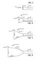
- FIG. 1is a perspective view of a preferred embodiment of the present invention in an elongate configuration
- FIG. 2is a side view of a preferred embodiment of the present invention.
- FIGS. 3-12are a sequence of perspective views of a preferred embodiment of the present invention being deployed from a delivery catheter;
- FIG. 13is a perspective view of a preferred embodiment of the present invention.
- FIG. 14is a first end view of the preferred embodiment of FIG. 13 ;
- FIG. 15is a second end view of the preferred embodiment of FIG. 13 ;
- FIG. 16is a side view of a preferred embodiment of the present invention.
- FIG. 17is a second end view of the preferred embodiment of FIG. 16 ;
- FIG. 18is a first end view of the preferred embodiment of FIG. 16 ;
- FIG. 19is a side view of a preferred embodiment of the present invention.
- FIG. 20is a first end view of the preferred embodiment of FIG. 19 ;
- FIG. 21is a second end view of the preferred embodiment of FIG. 19 ;
- FIG. 22is a partial perspective view of a preferred embodiment of the present invention.
- FIG. 23is a partial perspective view of a preferred embodiment of the present invention.
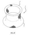
- FIG. 24is a perspective view of a preferred embodiment of the present invention.
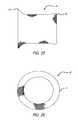
- FIG. 25is a side elevation of the embodiment of FIG. 24 ;
- FIG. 26is a second end view of the embodiment of FIG. 24 ;
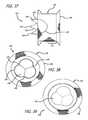
- FIGS. 27-36are a sequence of perspective views of a preferred embodiment of the present invention being deployed from a delivery catheter against a clear plastic tube representing a native valve;
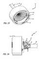
- FIG. 37is a side elevation of a preferred embodiment of the present invention.
- FIG. 38is an end view of a downstream side of the embodiment of FIG. 37 ;
- FIG. 39is an end view of an upstream side of the embodiment of FIG. 37 .
- the valve support 10includes a first end 12 , a second end 14 and an elongate tubular body 16 extending between the first end 12 and the second end 14 .
- the elongate tubular body 16is preferably formed from one or a plurality of braided strands 18 .
- the braided strands 18are strands of a super-elastic or shape memory material such as Nitinol.
- the strandsare braided to form a tube having a central lumen 20 passing therethrough.
- the tubular body 16is folded in half upon itself such that the second end 14 becomes a folded end and the first end 12 includes a plurality of unbraided strands.
- the tubular body 16is thus two-ply.
- the unbraided strands of the first end 12are gathered and joined together to form a plurality of gathered ends 22 .
- the gathered ends 22may be used as commissural points for attaching a prosthetic valve to the support structure 10 . (See, e.g. FIG. 2 ).
- the gathered ends 22may be used as attachment points for a wireform 24 defining a plurality of commissural points 26 .
- commissural points 26are positioned such that, when a valve is attached to the support structure in the extended configuration, the valve is longitudinally juxtaposed with the support structure rather than being located within the support structure.
- This juxtapositionallows the support structure 10 and valve to be packed into a very small catheter without damaging the delicate valve.
- This longitudinal juxtapositionmay be maintained when the support structure assumes a folded or constructed configuration (see FIG. 19 for example), or the valve may become folded within the support structure.
- FIGS. 3-6show the second end 14 emerging from the catheter 28 to expose a first layer 30 .
- the first layer 30is completely exposed and has assumed its constructed configuration.
- the first layer 30contracts longitudinally when fully deployed.
- a second layer 32beginning to emerge from the catheter 28 .
- the pre-set super-elastic foldinverts the mesh, such that a second, inner layer is formed within the first outer layer.
- the first layercan be deployed against the wall of the vascular structure (such as an artery, vein, valve or heart muscle).
- the physiciancan aid inversion of the mesh my advancing the deployment system.
- the mesh support structurecan be advanced in the vasculature such that it is deployed in a reverse direction (such as deployment through the apex of the heart ventricle or from the venous system), where the mesh inversion occurs as a result of pulling or retracting the deployment system.
- the second layer 32is fully deployed and the third layer 34 is fully exposed, but has not yet been inverted.
- Retracting the catheter 28 , relative to the device 10while advancing the catheter 28 slightly, relative to the target site, causes the third layer 34 to “pop” inwardly, thereby inverting itself against an inside surface of the second layer 32 , as seen in FIG. 11 .
- FIG. 12additional material has been ejected from the catheter 28 such that the third layer 34 is fully expanded against the second layer.
- additional materialhas been ejected from the catheter 28 such that the third layer 34 is fully expanded against the second layer.
- the stentless support structure 10emerges from the delivery catheter 28 gradually. This characteristic also allows the structure 10 to be pulled back into the delivery catheter 28 , in the event that it is desired to relocate the support structure 10 . Doing so causes the support structure 10 to reacquire its extended configuration.
- FIGS. 13-15show a support structure 10 having many layers 38 and a first end 12 with numerous gathered ends 22 formed from unbraided strands. Some of the gathered ends 22 are attached to a wireform 24 having three commissural points 26 . A prosthetic valve 36 , either harvested or manufactured, is attached to the wireform 24 .
- FIG. 15shows the internal lumen 20 of the support structure 10 .
- FIGS. 16-18show a support structure 10 having fewer layers 38 and a wireform 24 with a prosthetic valve 36 attached thereto.
- the first end 12(hidden), to which the wireform 24 is attached, has been preformed to fold inwardly upon deployment.
- the wireform 24 and prosthetic valve 36is located in the inner lumen 20 of the support structure 10 when the support structure 10 is in a constructed configuration.
- FIGS. 19-21show a support structure 10 with several layers 38 and a first end 12 preformed to have a smaller diameter than the rest of the layers and the second end 14 , which is folded.
- the terminal ends of the braided strands at the first end 12have not been formed into gathered ends. Rather, the wireform 24 is attached to the braids.
- the prosthetic valve 36is attached to the wireform 24 and has skirting tissue 40 , which is placed around the outside of the end 12 .
- the skirting tissue 40may be adhered to the first end 12 .
- FIG. 22shows a stentless support structure 10 with a folded end 14 , which has been folded back on itself, and a material 42 trapped between the two layers of the fold.
- the material 42is provided to further improve the paravalvular leak prevention and embolic trapping characteristics of the stentless support structure 10 .
- the material 42could consist of a non-woven material, woven or braided fabric, a polymer or other material.
- FIG. 23shows a stentless support structure 10 that includes a fiber 44 that is larger than the rest of the strands comprising the support structure 10 .
- FIG. 23demonstrates that strands of different sizes may be used in the braided support structure 10 without significantly affecting the minimum delivery size of the device. Different sized strands may be used in order to improve strength, provide stiffness, create valve attachment points, provide radiopaque markers, and the like.
- FIGS. 24-26show a stentless support structure 10 that has a first end 12 that has had the unbraided strands trimmed such that they do not extend past the first end 12 of the folded structure 10 .
- This embodimentmay be used to create, preserve or enlarge a lumen.
- a prosthetic valvemay or may not be attached to this embodiment.
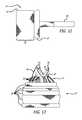
- FIGS. 27-36a deployment sequence of a preferred embodiment of the stentless support structure 10 is shown whereby a clear piece of tubing 46 is used to demonstrate a targeted location of a native vessel, such as a native valve.
- a native vesselsuch as a native valve.
- the delivery catheter 28is advanced beyond the targeted valve 46 and the stentless support 10 is starting to be ejected from the catheter 28 .
- FIG. 28enough of the stentless support 10 has been ejected that the second, folded end 14 has begun to curl back on itself slightly, forming a cuff 48 .
- the cuff 48is more visible and has assumed its full, deployed shape.
- the cuff 48acts as a catch that a physician can use to visually or tactilely locate the targeted valve 46 and seat the stentless support 10 thereagainst.
- the cuffalso acts to ensure the entire native lumen through the targeted valve 46 is now being filtered by the support 10 .
- blood flowis not significantly inhibited by the deployment of the stentless support structure 10 . Also shown in FIG.
- the 29is that the first layer 30 has been fully ejected from the catheter 28 , as has much of the second layer 32 .
- the first layer 30being very flexible prior to reinforcement by subsequent layers, is able to conform to any shape of the targeted vessel.
- the second layer 32has not yet inverted itself into the first layer 30 .
- FIG. 30the first layer 30 is deployed, the cuff 48 is acting against the valve 46 , and the second layer 32 has been inverted.
- material forming the third layer 34is ejected from the catheter 28 but the third layer 34 has not yet inverted.
- FIGS. 32-33the catheter 28 is being advanced to allow the third layer 34 to invert into the second layer 32 .
- the angle of FIG. 32shows the relatively low profile created by the first and second layers 30 and 32 , and how little resistance to blood flow is presented by the support structure 10 .
- FIG. 34the first end 12 has emerged from the catheter 12 , and the gathered ends 22 are showing.
- a wireform 24is attached to some of the gathered ends 22 and is nearly completely deployed from the delivery catheter 28 .
- FIGS. 35-36the support structure 10 has been completely released from the catheter 28 .
- FIG. 36shows the size of the lumen 20 of the support structure 10 .
- FIGS. 37-39show a preferred embodiment 100 of the present invention including a mesh support structure 102 , a wireform 104 and a valve 106 .
- the support structure 102differs slightly from support structure 10 , described previously, as it is constructed from a two individual wires 108 .
- the two free ends of the wireare spliced together. As such, there are no free wire ends and the structure can be loaded into a delivery catheter in a single-ply state (not shown).
- the support structure 102is folded once to form a two-ply device.
- the support structure 102is preferably formed of a memory alloy such as Nitinol.
- the single-wire constructionallows the device to be compressed into an extremely small catheter, such as one sized 16 Fr or smaller.
- the support structuregains rigidity by the two-ply deployed configuration, radial strength is a function of a several factors and can thus be varied widely.
- radial strengthmay be increased by incorporating more folds or layers into the deployed configuration of the support structure 102 .
- the three-ply configuration shown in FIGS. 37-39is the most preferred configuration because it only has to be folded in on itself twice, making deployment less complicated.
- support structure 102is made from a single-wire, and can thus be loaded into a catheter in a single-ply configuration, a larger diameter wire may be used while maintaining a small diameter elongated profile.
- Support structures 102have been constructed according to the present invention using single wires having diameters between 0.005 and 0.010 inches in diameter. Preferably, the diameter of the wire is between 0.007 and 0.008 inches.
- strengthmay be increased by increasing the braid density. A tighter braid will result in a stronger support.
- the strengthmay be increased by altering the heat setting parameters.
- Super-elastic and shape memory alloyssuch as Nitinol, attain their deployed shape within the vasculature by being heat set.
- the wiresare held in a desired configuration and heated to a predetermined temperature for a predetermined period of time. After the wires cool, they become set to the new configuration. If the wires are later disfigured, they will return to the set configuration upon heating or simply releasing the wires.
- the force with which a super-elastic or shape memory alloy returns to a set configurationcan be increased by modifying the temperature at which the configuration is set, or by modifying the period of time the alloy is maintained at the elevated setting temperature.
- Stiffer support structurescan be made using the same Nitinol wire by setting the structure at a temperature other than 530° C. or by setting the structure at 530° C. for a time other than 7 minutes, or both.
- the device 100includes a wireform 104 , to which a valve 106 is attached.
- the wireform 104form commissural points 109 separated by arcuate portions 110 .
- the arcuate portions 110are attached to an inside surface of the support structure 102 .
- the commissural points 109facilitate natural and efficient opening and closing of the valve 106 .
- the valve commissural pointscan be attached to an outer surface of the support structure (not shown).
- the valve 106may be any form of prosthetic or harvested biological valve.
- the valve 106is a valve having three leaflets.
- the valve 106is sutured or otherwise attached to the wireform 104 .
- the valve 106is cut or constructed to include a skirt portion 112 which continues along the length of the support structure 102 in its deployed configuration.
Landscapes
- Health & Medical Sciences (AREA)
- Cardiology (AREA)
- Engineering & Computer Science (AREA)
- Biomedical Technology (AREA)
- Life Sciences & Earth Sciences (AREA)
- Public Health (AREA)
- Heart & Thoracic Surgery (AREA)
- Vascular Medicine (AREA)
- Oral & Maxillofacial Surgery (AREA)
- Animal Behavior & Ethology (AREA)
- General Health & Medical Sciences (AREA)
- Transplantation (AREA)
- Veterinary Medicine (AREA)
- Gastroenterology & Hepatology (AREA)
- Pulmonology (AREA)
- Prostheses (AREA)
- Surgical Instruments (AREA)
- Media Introduction/Drainage Providing Device (AREA)
Abstract
Description
Claims (14)
Priority Applications (1)
| Application Number | Priority Date | Filing Date | Title |
|---|---|---|---|
| US14/635,951US9439760B2 (en) | 2005-05-27 | 2015-03-02 | Stentless support structure |
Applications Claiming Priority (5)
| Application Number | Priority Date | Filing Date | Title |
|---|---|---|---|
| US68543305P | 2005-05-27 | 2005-05-27 | |
| US68534905P | 2005-05-27 | 2005-05-27 | |
| US70959505P | 2005-08-18 | 2005-08-18 | |
| US11/443,814US8974523B2 (en) | 2005-05-27 | 2006-05-30 | Stentless support structure |
| US14/635,951US9439760B2 (en) | 2005-05-27 | 2015-03-02 | Stentless support structure |
Related Parent Applications (1)
| Application Number | Title | Priority Date | Filing Date |
|---|---|---|---|
| US11/443,814DivisionUS8974523B2 (en) | 2005-05-27 | 2006-05-30 | Stentless support structure |
Publications (2)
| Publication Number | Publication Date |
|---|---|
| US20150164638A1 US20150164638A1 (en) | 2015-06-18 |
| US9439760B2true US9439760B2 (en) | 2016-09-13 |
Family
ID=37453013
Family Applications (10)
| Application Number | Title | Priority Date | Filing Date |
|---|---|---|---|
| US11/443,814Active2028-04-09US8974523B2 (en) | 2005-05-27 | 2006-05-30 | Stentless support structure |
| US13/192,375Active2026-09-24US9271831B2 (en) | 2005-05-27 | 2011-07-27 | Stentless support structure |
| US13/458,023Active2027-02-07US9180002B2 (en) | 2005-05-27 | 2012-04-27 | Stentless support structure |
| US13/651,249AbandonedUS20130144383A1 (en) | 2005-05-27 | 2012-10-12 | Stentless Support Structure |
| US13/895,230ActiveUS9168132B2 (en) | 2005-05-27 | 2013-05-15 | Stentless support structure |
| US14/635,951Expired - Fee RelatedUS9439760B2 (en) | 2005-05-27 | 2015-03-02 | Stentless support structure |
| US15/282,617ActiveUS10080655B2 (en) | 2005-05-27 | 2016-09-30 | Stentless support structure |
| US15/284,227ActiveUS9814575B2 (en) | 2005-05-27 | 2016-10-03 | Stentless support structure |
| US16/114,052ActiveUS11026784B2 (en) | 2005-05-27 | 2018-08-27 | Stentless support structure |
| US17/308,892AbandonedUS20210322157A1 (en) | 2005-05-27 | 2021-05-05 | Stentless Support Structure |
Family Applications Before (5)
| Application Number | Title | Priority Date | Filing Date |
|---|---|---|---|
| US11/443,814Active2028-04-09US8974523B2 (en) | 2005-05-27 | 2006-05-30 | Stentless support structure |
| US13/192,375Active2026-09-24US9271831B2 (en) | 2005-05-27 | 2011-07-27 | Stentless support structure |
| US13/458,023Active2027-02-07US9180002B2 (en) | 2005-05-27 | 2012-04-27 | Stentless support structure |
| US13/651,249AbandonedUS20130144383A1 (en) | 2005-05-27 | 2012-10-12 | Stentless Support Structure |
| US13/895,230ActiveUS9168132B2 (en) | 2005-05-27 | 2013-05-15 | Stentless support structure |
Family Applications After (4)
| Application Number | Title | Priority Date | Filing Date |
|---|---|---|---|
| US15/282,617ActiveUS10080655B2 (en) | 2005-05-27 | 2016-09-30 | Stentless support structure |
| US15/284,227ActiveUS9814575B2 (en) | 2005-05-27 | 2016-10-03 | Stentless support structure |
| US16/114,052ActiveUS11026784B2 (en) | 2005-05-27 | 2018-08-27 | Stentless support structure |
| US17/308,892AbandonedUS20210322157A1 (en) | 2005-05-27 | 2021-05-05 | Stentless Support Structure |
Country Status (7)
| Country | Link |
|---|---|
| US (10) | US8974523B2 (en) |
| EP (3) | EP3482717B1 (en) |
| JP (6) | JP5289049B2 (en) |
| CN (2) | CN101991478B (en) |
| AU (1) | AU2006251938B2 (en) |
| CA (1) | CA2613958C (en) |
| WO (1) | WO2006128193A2 (en) |
Families Citing this family (333)
| Publication number | Priority date | Publication date | Assignee | Title |
|---|---|---|---|---|
| US6006134A (en) | 1998-04-30 | 1999-12-21 | Medtronic, Inc. | Method and device for electronically controlling the beating of a heart using venous electrical stimulation of nerve fibers |
| US7018401B1 (en) | 1999-02-01 | 2006-03-28 | Board Of Regents, The University Of Texas System | Woven intravascular devices and methods for making the same and apparatus for delivery of the same |
| US8579966B2 (en) | 1999-11-17 | 2013-11-12 | Medtronic Corevalve Llc | Prosthetic valve for transluminal delivery |
| US8016877B2 (en) | 1999-11-17 | 2011-09-13 | Medtronic Corevalve Llc | Prosthetic valve for transluminal delivery |
| US7018406B2 (en) | 1999-11-17 | 2006-03-28 | Corevalve Sa | Prosthetic valve for transluminal delivery |
| US8241274B2 (en) | 2000-01-19 | 2012-08-14 | Medtronic, Inc. | Method for guiding a medical device |
| US7749245B2 (en) | 2000-01-27 | 2010-07-06 | Medtronic, Inc. | Cardiac valve procedure methods and devices |
| AU2001273088A1 (en) | 2000-06-30 | 2002-01-30 | Viacor Incorporated | Intravascular filter with debris entrapment mechanism |
| EP1309289A2 (en) | 2000-08-18 | 2003-05-14 | Atritech, Inc. | Expandable implant devices for filtering blood flow from atrial appendages |
| US7544206B2 (en) | 2001-06-29 | 2009-06-09 | Medtronic, Inc. | Method and apparatus for resecting and replacing an aortic valve |
| US8771302B2 (en) | 2001-06-29 | 2014-07-08 | Medtronic, Inc. | Method and apparatus for resecting and replacing an aortic valve |
| US8623077B2 (en) | 2001-06-29 | 2014-01-07 | Medtronic, Inc. | Apparatus for replacing a cardiac valve |
| FR2826863B1 (en) | 2001-07-04 | 2003-09-26 | Jacques Seguin | ASSEMBLY FOR PLACING A PROSTHETIC VALVE IN A BODY CONDUIT |
| FR2828091B1 (en) | 2001-07-31 | 2003-11-21 | Seguin Jacques | ASSEMBLY ALLOWING THE PLACEMENT OF A PROTHETIC VALVE IN A BODY DUCT |
| US7097659B2 (en) | 2001-09-07 | 2006-08-29 | Medtronic, Inc. | Fixation band for affixing a prosthetic heart valve to tissue |
| US7335218B2 (en) | 2002-08-28 | 2008-02-26 | Heart Leaflet Technologies, Inc. | Delivery device for leaflet valve |
| US7025791B2 (en)* | 2002-12-02 | 2006-04-11 | Gi Dynamics, Inc. | Bariatric sleeve |
| WO2004049982A2 (en) | 2002-12-02 | 2004-06-17 | Gi Dynamics, Inc. | Bariatric sleeve |
| US7608114B2 (en) | 2002-12-02 | 2009-10-27 | Gi Dynamics, Inc. | Bariatric sleeve |
| US9579194B2 (en) | 2003-10-06 | 2017-02-28 | Medtronic ATS Medical, Inc. | Anchoring structure with concave landing zone |
| AU2004305450B2 (en) | 2003-12-09 | 2009-01-08 | Gi Dynamics, Inc. | Intestinal sleeve |
| US20120041550A1 (en) | 2003-12-23 | 2012-02-16 | Sadra Medical, Inc. | Methods and Apparatus for Endovascular Heart Valve Replacement Comprising Tissue Grasping Elements |
| US7329279B2 (en) | 2003-12-23 | 2008-02-12 | Sadra Medical, Inc. | Methods and apparatus for endovascularly replacing a patient's heart valve |
| US8603160B2 (en) | 2003-12-23 | 2013-12-10 | Sadra Medical, Inc. | Method of using a retrievable heart valve anchor with a sheath |
| US7381219B2 (en) | 2003-12-23 | 2008-06-03 | Sadra Medical, Inc. | Low profile heart valve and delivery system |
| US11278398B2 (en) | 2003-12-23 | 2022-03-22 | Boston Scientific Scimed, Inc. | Methods and apparatus for endovascular heart valve replacement comprising tissue grasping elements |
| EP2529699B1 (en) | 2003-12-23 | 2014-01-29 | Sadra Medical, Inc. | Repositionable heart valve |
| US7445631B2 (en) | 2003-12-23 | 2008-11-04 | Sadra Medical, Inc. | Methods and apparatus for endovascularly replacing a patient's heart valve |
| US8579962B2 (en) | 2003-12-23 | 2013-11-12 | Sadra Medical, Inc. | Methods and apparatus for performing valvuloplasty |
| US7824443B2 (en) | 2003-12-23 | 2010-11-02 | Sadra Medical, Inc. | Medical implant delivery and deployment tool |
| US8287584B2 (en) | 2005-11-14 | 2012-10-16 | Sadra Medical, Inc. | Medical implant deployment tool |
| US9526609B2 (en) | 2003-12-23 | 2016-12-27 | Boston Scientific Scimed, Inc. | Methods and apparatus for endovascularly replacing a patient's heart valve |
| US8343213B2 (en) | 2003-12-23 | 2013-01-01 | Sadra Medical, Inc. | Leaflet engagement elements and methods for use thereof |
| US9005273B2 (en) | 2003-12-23 | 2015-04-14 | Sadra Medical, Inc. | Assessing the location and performance of replacement heart valves |
| US20050137694A1 (en) | 2003-12-23 | 2005-06-23 | Haug Ulrich R. | Methods and apparatus for endovascularly replacing a patient's heart valve |
| US20050137687A1 (en) | 2003-12-23 | 2005-06-23 | Sadra Medical | Heart valve anchor and method |
| US8840663B2 (en) | 2003-12-23 | 2014-09-23 | Sadra Medical, Inc. | Repositionable heart valve method |
| US7780725B2 (en) | 2004-06-16 | 2010-08-24 | Sadra Medical, Inc. | Everting heart valve |
| US8182528B2 (en) | 2003-12-23 | 2012-05-22 | Sadra Medical, Inc. | Locking heart valve anchor |
| US7959666B2 (en) | 2003-12-23 | 2011-06-14 | Sadra Medical, Inc. | Methods and apparatus for endovascularly replacing a heart valve |
| US8828078B2 (en) | 2003-12-23 | 2014-09-09 | Sadra Medical, Inc. | Methods and apparatus for endovascular heart valve replacement comprising tissue grasping elements |
| ITTO20040135A1 (en) | 2004-03-03 | 2004-06-03 | Sorin Biomedica Cardio Spa | CARDIAC VALVE PROSTHESIS |
| BRPI0510107A (en) | 2004-04-23 | 2007-09-25 | 3F Therapeutics Inc | implantable protein valve |
| DE102005003632A1 (en) | 2005-01-20 | 2006-08-17 | Fraunhofer-Gesellschaft zur Förderung der angewandten Forschung e.V. | Catheter for the transvascular implantation of heart valve prostheses |
| ITTO20050074A1 (en) | 2005-02-10 | 2006-08-11 | Sorin Biomedica Cardio Srl | CARDIAC VALVE PROSTHESIS |
| US7962208B2 (en) | 2005-04-25 | 2011-06-14 | Cardiac Pacemakers, Inc. | Method and apparatus for pacing during revascularization |
| US7914569B2 (en) | 2005-05-13 | 2011-03-29 | Medtronics Corevalve Llc | Heart valve prosthesis and methods of manufacture and use |
| CN101991478B (en) | 2005-05-27 | 2013-04-24 | 心叶科技公司 | Stentless support structure |
| US7712606B2 (en) | 2005-09-13 | 2010-05-11 | Sadra Medical, Inc. | Two-part package for medical implant |
| EP1945142B1 (en) | 2005-09-26 | 2013-12-25 | Medtronic, Inc. | Prosthetic cardiac and venous valves |
| US20070213813A1 (en) | 2005-12-22 | 2007-09-13 | Symetis Sa | Stent-valves for valve replacement and associated methods and systems for surgery |
| EP1988851A2 (en) | 2006-02-14 | 2008-11-12 | Sadra Medical, Inc. | Systems and methods for delivering a medical implant |
| US8075615B2 (en) | 2006-03-28 | 2011-12-13 | Medtronic, Inc. | Prosthetic cardiac valve formed from pericardium material and methods of making same |
| US8834564B2 (en) | 2006-09-19 | 2014-09-16 | Medtronic, Inc. | Sinus-engaging valve fixation member |
| US11304800B2 (en) | 2006-09-19 | 2022-04-19 | Medtronic Ventor Technologies Ltd. | Sinus-engaging valve fixation member |
| US8876894B2 (en) | 2006-09-19 | 2014-11-04 | Medtronic Ventor Technologies Ltd. | Leaflet-sensitive valve fixation member |
| DK2083901T3 (en) | 2006-10-16 | 2018-02-26 | Medtronic Ventor Tech Ltd | TRANSAPICAL DELIVERY SYSTEM WITH VENTRICULO-ARTERIAL OVERFLOW BYPASS |
| MX2009004291A (en) | 2006-10-22 | 2009-09-07 | Idev Technologies Inc | Methods for securing strand ends and the resulting devices. |
| US9883943B2 (en) | 2006-12-05 | 2018-02-06 | Valtech Cardio, Ltd. | Implantation of repair devices in the heart |
| JP5593545B2 (en) | 2006-12-06 | 2014-09-24 | メドトロニック シーブイ ルクセンブルク エス.アー.エール.エル. | System and method for transapical delivery of a self-expanding valve secured to an annulus |
| AU2008216670B2 (en)* | 2007-02-15 | 2013-10-17 | Medtronic, Inc. | Multi-layered stents and methods of implanting |
| EP2129332B1 (en) | 2007-02-16 | 2019-01-23 | Medtronic, Inc. | Replacement prosthetic heart valves |
| US7896915B2 (en) | 2007-04-13 | 2011-03-01 | Jenavalve Technology, Inc. | Medical device for treating a heart valve insufficiency |
| FR2915087B1 (en) | 2007-04-20 | 2021-11-26 | Corevalve Inc | IMPLANT FOR TREATMENT OF A HEART VALVE, IN PARTICULAR OF A MITRAL VALVE, EQUIPMENT INCLUDING THIS IMPLANT AND MATERIAL FOR PLACING THIS IMPLANT. |
| US8747458B2 (en) | 2007-08-20 | 2014-06-10 | Medtronic Ventor Technologies Ltd. | Stent loading tool and method for use thereof |
| DE202008018557U1 (en) | 2007-08-21 | 2015-10-26 | Symetis Sa | A replacement flap |
| EP3443938B1 (en) | 2007-09-26 | 2024-01-24 | St. Jude Medical, LLC | Collapsible prosthetic heart valves |
| US9532868B2 (en) | 2007-09-28 | 2017-01-03 | St. Jude Medical, Inc. | Collapsible-expandable prosthetic heart valves with structures for clamping native tissue |
| US10856970B2 (en) | 2007-10-10 | 2020-12-08 | Medtronic Ventor Technologies Ltd. | Prosthetic heart valve for transfemoral delivery |
| US9848981B2 (en) | 2007-10-12 | 2017-12-26 | Mayo Foundation For Medical Education And Research | Expandable valve prosthesis with sealing mechanism |
| CN101965162B (en)* | 2007-12-15 | 2014-12-10 | 恩多斯潘有限公司 | Extra-vascular wrapping for treating aneurysmatic aorta in conjunction with endovascular stent-graft and methods thereof |
| US9393115B2 (en) | 2008-01-24 | 2016-07-19 | Medtronic, Inc. | Delivery systems and methods of implantation for prosthetic heart valves |
| US9149358B2 (en) | 2008-01-24 | 2015-10-06 | Medtronic, Inc. | Delivery systems for prosthetic heart valves |
| US8628566B2 (en) | 2008-01-24 | 2014-01-14 | Medtronic, Inc. | Stents for prosthetic heart valves |
| US9089422B2 (en) | 2008-01-24 | 2015-07-28 | Medtronic, Inc. | Markers for prosthetic heart valves |
| CA2714062A1 (en) | 2008-01-24 | 2009-07-30 | Medtronic, Inc. | Stents for prosthetic heart valves |
| US8157853B2 (en) | 2008-01-24 | 2012-04-17 | Medtronic, Inc. | Delivery systems and methods of implantation for prosthetic heart valves |
| US9044318B2 (en) | 2008-02-26 | 2015-06-02 | Jenavalve Technology Gmbh | Stent for the positioning and anchoring of a valvular prosthesis |
| BR112012021347A2 (en) | 2008-02-26 | 2019-09-24 | Jenavalve Tecnology Inc | stent for positioning and anchoring a valve prosthesis at an implantation site in a patient's heart |
| WO2009108355A1 (en) | 2008-02-28 | 2009-09-03 | Medtronic, Inc. | Prosthetic heart valve systems |
| US8313525B2 (en) | 2008-03-18 | 2012-11-20 | Medtronic Ventor Technologies, Ltd. | Valve suturing and implantation procedures |
| US8430927B2 (en) | 2008-04-08 | 2013-04-30 | Medtronic, Inc. | Multiple orifice implantable heart valve and methods of implantation |
| US8696743B2 (en) | 2008-04-23 | 2014-04-15 | Medtronic, Inc. | Tissue attachment devices and methods for prosthetic heart valves |
| US8312825B2 (en) | 2008-04-23 | 2012-11-20 | Medtronic, Inc. | Methods and apparatuses for assembly of a pericardial prosthetic heart valve |
| EP2119417B2 (en) | 2008-05-16 | 2020-04-29 | Sorin Group Italia S.r.l. | Atraumatic prosthetic heart valve prosthesis |
| EP2296744B1 (en) | 2008-06-16 | 2019-07-31 | Valtech Cardio, Ltd. | Annuloplasty devices |
| EP2815724B2 (en) | 2008-07-15 | 2024-03-13 | St. Jude Medical, Inc. | Collapsible and re-expandable prosthetic heart valve cuff designs and complementary technological applications |
| US9351715B2 (en)* | 2008-07-24 | 2016-05-31 | St. Jude Medical, Cardiology Division, Inc. | Multi-layered medical device for treating a target site and associated method |
| US9232992B2 (en)* | 2008-07-24 | 2016-01-12 | Aga Medical Corporation | Multi-layered medical device for treating a target site and associated method |
| WO2010031060A1 (en) | 2008-09-15 | 2010-03-18 | Medtronic Ventor Technologies Ltd. | Prosthetic heart valve having identifiers for aiding in radiographic positioning |
| US8721714B2 (en) | 2008-09-17 | 2014-05-13 | Medtronic Corevalve Llc | Delivery system for deployment of medical devices |
| EP3238661B1 (en) | 2008-10-10 | 2019-05-22 | Boston Scientific Scimed, Inc. | Medical devices and delivery systems for delivering medical devices |
| US8137398B2 (en) | 2008-10-13 | 2012-03-20 | Medtronic Ventor Technologies Ltd | Prosthetic valve having tapered tip when compressed for delivery |
| US8986361B2 (en) | 2008-10-17 | 2015-03-24 | Medtronic Corevalve, Inc. | Delivery system for deployment of medical devices |
| DE102009006180A1 (en)* | 2008-10-29 | 2010-05-06 | Acandis Gmbh & Co. Kg | Medical implant and method for manufacturing an implant |
| US10517719B2 (en) | 2008-12-22 | 2019-12-31 | Valtech Cardio, Ltd. | Implantation of repair devices in the heart |
| EP2682072A1 (en) | 2008-12-23 | 2014-01-08 | Sorin Group Italia S.r.l. | Expandable prosthetic valve having anchoring appendages |
| AU2010218384B2 (en) | 2009-02-27 | 2014-11-20 | St. Jude Medical, Inc. | Stent features for collapsible prosthetic heart valves |
| GB0905444D0 (en)* | 2009-03-30 | 2009-05-13 | Ucl Business Plc | Heart valve prosthesis |
| EP2246011B1 (en) | 2009-04-27 | 2014-09-03 | Sorin Group Italia S.r.l. | Prosthetic vascular conduit |
| CA3009244C (en) | 2009-06-23 | 2020-04-28 | Endospan Ltd. | Vascular prostheses for treating aneurysms |
| WO2011004374A1 (en) | 2009-07-09 | 2011-01-13 | Endospan Ltd. | Apparatus for closure of a lumen and methods of using the same |
| US8845722B2 (en)* | 2009-08-03 | 2014-09-30 | Shlomo Gabbay | Heart valve prosthesis and method of implantation thereof |
| US10034748B2 (en) | 2009-09-18 | 2018-07-31 | The Regents Of The University Of California | Endovascular prosthetic heart valve replacement |
| US8808369B2 (en) | 2009-10-05 | 2014-08-19 | Mayo Foundation For Medical Education And Research | Minimally invasive aortic valve replacement |
| US9180007B2 (en) | 2009-10-29 | 2015-11-10 | Valtech Cardio, Ltd. | Apparatus and method for guide-wire based advancement of an adjustable implant |
| US8870950B2 (en) | 2009-12-08 | 2014-10-28 | Mitral Tech Ltd. | Rotation-based anchoring of an implant |
| US9468517B2 (en) | 2010-02-08 | 2016-10-18 | Endospan Ltd. | Thermal energy application for prevention and management of endoleaks in stent-grafts |
| US9226826B2 (en) | 2010-02-24 | 2016-01-05 | Medtronic, Inc. | Transcatheter valve structure and methods for valve delivery |
| US20110208289A1 (en)* | 2010-02-25 | 2011-08-25 | Endospan Ltd. | Flexible Stent-Grafts |
| US8795354B2 (en)* | 2010-03-05 | 2014-08-05 | Edwards Lifesciences Corporation | Low-profile heart valve and delivery system |
| US20110224785A1 (en) | 2010-03-10 | 2011-09-15 | Hacohen Gil | Prosthetic mitral valve with tissue anchors |
| US8652204B2 (en) | 2010-04-01 | 2014-02-18 | Medtronic, Inc. | Transcatheter valve with torsion spring fixation and related systems and methods |
| US10568628B2 (en)* | 2017-05-23 | 2020-02-25 | Muffin Incorporated | Closing device for tissue openings |
| US8579964B2 (en) | 2010-05-05 | 2013-11-12 | Neovasc Inc. | Transcatheter mitral valve prosthesis |
| AU2011250971B2 (en)* | 2010-05-10 | 2015-05-07 | Hlt, Inc. | Stentless support structure |
| US10856978B2 (en) | 2010-05-20 | 2020-12-08 | Jenavalve Technology, Inc. | Catheter system |
| IT1400327B1 (en) | 2010-05-21 | 2013-05-24 | Sorin Biomedica Cardio Srl | SUPPORT DEVICE FOR VALVULAR PROSTHESIS AND CORRESPONDING CORRESPONDENT. |
| WO2011147849A1 (en) | 2010-05-25 | 2011-12-01 | Jenavalve Technology Inc. | Prosthetic heart valve and transcatheter delivered endoprosthesis comprising a prosthetic heart valve and a stent |
| AU2011275468B2 (en) | 2010-07-09 | 2014-02-06 | Highlife Sas | Transcatheter atrio-ventricular valve prosthesis |
| US9132009B2 (en) | 2010-07-21 | 2015-09-15 | Mitraltech Ltd. | Guide wires with commissural anchors to advance a prosthetic valve |
| US9763657B2 (en) | 2010-07-21 | 2017-09-19 | Mitraltech Ltd. | Techniques for percutaneous mitral valve replacement and sealing |
| US11653910B2 (en) | 2010-07-21 | 2023-05-23 | Cardiovalve Ltd. | Helical anchor implantation |
| US8992604B2 (en)* | 2010-07-21 | 2015-03-31 | Mitraltech Ltd. | Techniques for percutaneous mitral valve replacement and sealing |
| US8696737B2 (en) | 2010-08-11 | 2014-04-15 | Hlt, Inc. | Reinforced commissural support structure |
| WO2012030598A2 (en) | 2010-09-01 | 2012-03-08 | Medtronic Vascular Galway Limited | Prosthetic valve support structure |
| US9463269B2 (en) | 2010-09-10 | 2016-10-11 | W. L. Gore & Associates, Inc. | Anastomotic devices and methods |
| AU2011300644B2 (en) | 2010-09-10 | 2015-08-20 | Symetis Sa | Valve replacement devices and a system comprising the valve replacement device and a delivery device therefor |
| US8845720B2 (en)* | 2010-09-27 | 2014-09-30 | Edwards Lifesciences Corporation | Prosthetic heart valve frame with flexible commissures |
| DK4233795T3 (en) | 2010-10-05 | 2024-08-26 | Edwards Lifesciences Corp | Prosthetic heart valve |
| CN101961274A (en)* | 2010-10-27 | 2011-02-02 | 先健科技(深圳)有限公司 | Blood vessel necking device and controlled release system |
| US8475372B2 (en) | 2010-10-29 | 2013-07-02 | Medtronic Vascular, Inc. | Implantable medical sensor and fixation system |
| US8864676B2 (en) | 2010-10-29 | 2014-10-21 | Medtronic Vascular, Inc. | Implantable medical sensor and fixation system |
| EP2484309B1 (en)* | 2011-02-02 | 2019-04-10 | Shlomo Gabbay | Heart valve prosthesis |
| ES2641902T3 (en) | 2011-02-14 | 2017-11-14 | Sorin Group Italia S.R.L. | Sutureless anchoring device for cardiac valve prostheses |
| EP2486894B1 (en) | 2011-02-14 | 2021-06-09 | Sorin Group Italia S.r.l. | Sutureless anchoring device for cardiac valve prostheses |
| WO2012111006A1 (en) | 2011-02-17 | 2012-08-23 | Endospan Ltd. | Vascular bands and delivery systems therefor |
| WO2012117395A1 (en) | 2011-03-02 | 2012-09-07 | Endospan Ltd. | Reduced-strain extra- vascular ring for treating aortic aneurysm |
| EP2688516B1 (en) | 2011-03-21 | 2022-08-17 | Cephea Valve Technologies, Inc. | Disk-based valve apparatus |
| US9968446B2 (en) | 2011-03-23 | 2018-05-15 | The Regents Of The University Of California | Tubular scaffold for fabrication of heart valves |
| US8727996B2 (en) | 2011-04-20 | 2014-05-20 | Medtronic Vascular, Inc. | Delivery system for implantable medical device |
| US9308087B2 (en) | 2011-04-28 | 2016-04-12 | Neovasc Tiara Inc. | Sequentially deployed transcatheter mitral valve prosthesis |
| US9554897B2 (en) | 2011-04-28 | 2017-01-31 | Neovasc Tiara Inc. | Methods and apparatus for engaging a valve prosthesis with tissue |
| EP2520251A1 (en) | 2011-05-05 | 2012-11-07 | Symetis SA | Method and Apparatus for Compressing Stent-Valves |
| EP3967268A1 (en) | 2011-05-16 | 2022-03-16 | Hlt, Inc. | Inversion delivery device for a prosthesis |
| US9522064B2 (en) | 2011-05-16 | 2016-12-20 | Hlt, Inc. | Inversion delivery device and method for a prosthesis |
| EP2720641B1 (en) | 2011-06-15 | 2019-02-20 | St. Jude Medical, LLC | Prosthetic heart valve with multi-layer stent |
| US20140303719A1 (en)* | 2011-06-24 | 2014-10-09 | Inceptus Medical, Llc | Percutaneously implantable artificial heart valve system and associated methods and devices |
| US9254209B2 (en) | 2011-07-07 | 2016-02-09 | Endospan Ltd. | Stent fixation with reduced plastic deformation |
| US8998976B2 (en) | 2011-07-12 | 2015-04-07 | Boston Scientific Scimed, Inc. | Coupling system for medical devices |
| US8852272B2 (en) | 2011-08-05 | 2014-10-07 | Mitraltech Ltd. | Techniques for percutaneous mitral valve replacement and sealing |
| US20140324164A1 (en) | 2011-08-05 | 2014-10-30 | Mitraltech Ltd. | Techniques for percutaneous mitral valve replacement and sealing |
| WO2013021374A2 (en) | 2011-08-05 | 2013-02-14 | Mitraltech Ltd. | Techniques for percutaneous mitral valve replacement and sealing |
| EP2739214B1 (en) | 2011-08-05 | 2018-10-10 | Cardiovalve Ltd | Percutaneous mitral valve replacement and sealing |
| US9839510B2 (en) | 2011-08-28 | 2017-12-12 | Endospan Ltd. | Stent-grafts with post-deployment variable radial displacement |
| US9427339B2 (en) | 2011-10-30 | 2016-08-30 | Endospan Ltd. | Triple-collar stent-graft |
| US9131926B2 (en) | 2011-11-10 | 2015-09-15 | Boston Scientific Scimed, Inc. | Direct connect flush system |
| US8940014B2 (en) | 2011-11-15 | 2015-01-27 | Boston Scientific Scimed, Inc. | Bond between components of a medical device |
| US8951243B2 (en) | 2011-12-03 | 2015-02-10 | Boston Scientific Scimed, Inc. | Medical device handle |
| US9597204B2 (en) | 2011-12-04 | 2017-03-21 | Endospan Ltd. | Branched stent-graft system |
| US9510945B2 (en) | 2011-12-20 | 2016-12-06 | Boston Scientific Scimed Inc. | Medical device handle |
| US9277993B2 (en) | 2011-12-20 | 2016-03-08 | Boston Scientific Scimed, Inc. | Medical device delivery systems |
| EP2842517A1 (en) | 2011-12-29 | 2015-03-04 | Sorin Group Italia S.r.l. | A kit for implanting prosthetic vascular conduits |
| WO2013112547A1 (en) | 2012-01-25 | 2013-08-01 | Boston Scientific Scimed, Inc. | Valve assembly with a bioabsorbable gasket and a replaceable valve implant |
| WO2013171730A1 (en) | 2012-05-15 | 2013-11-21 | Endospan Ltd. | Stent-graft with fixation elements that are radially confined for delivery |
| CN104684504B (en) | 2012-05-16 | 2017-06-23 | Hlt股份有限公司 | Inversion transfer device and method for prosthesis |
| US9345573B2 (en) | 2012-05-30 | 2016-05-24 | Neovasc Tiara Inc. | Methods and apparatus for loading a prosthesis onto a delivery system |
| US9301835B2 (en)* | 2012-06-04 | 2016-04-05 | Edwards Lifesciences Corporation | Pre-assembled bioprosthetic valve and sealed conduit |
| US9883941B2 (en) | 2012-06-19 | 2018-02-06 | Boston Scientific Scimed, Inc. | Replacement heart valve |
| US9283072B2 (en) | 2012-07-25 | 2016-03-15 | W. L. Gore & Associates, Inc. | Everting transcatheter valve and methods |
| US10376360B2 (en) | 2012-07-27 | 2019-08-13 | W. L. Gore & Associates, Inc. | Multi-frame prosthetic valve apparatus and methods |
| US9351648B2 (en) | 2012-08-24 | 2016-05-31 | Medtronic, Inc. | Implantable medical device electrode assembly |
| EP2911593B1 (en) | 2012-10-23 | 2020-03-25 | Valtech Cardio, Ltd. | Percutaneous tissue anchor techniques |
| US8628571B1 (en) | 2012-11-13 | 2014-01-14 | Mitraltech Ltd. | Percutaneously-deliverable mechanical valve |
| US10039638B2 (en) | 2012-12-19 | 2018-08-07 | W. L. Gore & Associates, Inc. | Geometric prosthetic heart valves |
| US9101469B2 (en) | 2012-12-19 | 2015-08-11 | W. L. Gore & Associates, Inc. | Prosthetic heart valve with leaflet shelving |
| US9144492B2 (en) | 2012-12-19 | 2015-09-29 | W. L. Gore & Associates, Inc. | Truncated leaflet for prosthetic heart valves, preformed valve |
| US9737398B2 (en) | 2012-12-19 | 2017-08-22 | W. L. Gore & Associates, Inc. | Prosthetic valves, frames and leaflets and methods thereof |
| US9968443B2 (en) | 2012-12-19 | 2018-05-15 | W. L. Gore & Associates, Inc. | Vertical coaptation zone in a planar portion of prosthetic heart valve leaflet |
| US10321986B2 (en) | 2012-12-19 | 2019-06-18 | W. L. Gore & Associates, Inc. | Multi-frame prosthetic heart valve |
| US10966820B2 (en) | 2012-12-19 | 2021-04-06 | W. L. Gore & Associates, Inc. | Geometric control of bending character in prosthetic heart valve leaflets |
| US20150351906A1 (en) | 2013-01-24 | 2015-12-10 | Mitraltech Ltd. | Ventricularly-anchored prosthetic valves |
| WO2014165010A1 (en)* | 2013-03-12 | 2014-10-09 | The Regents Of The University Of California | Tubular scaffold for fabrication of heart valves |
| US9339274B2 (en) | 2013-03-12 | 2016-05-17 | St. Jude Medical, Cardiology Division, Inc. | Paravalvular leak occlusion device for self-expanding heart valves |
| US9398951B2 (en) | 2013-03-12 | 2016-07-26 | St. Jude Medical, Cardiology Division, Inc. | Self-actuating sealing portions for paravalvular leak protection |
| EP2967849B1 (en) | 2013-03-12 | 2025-08-13 | St. Jude Medical, Cardiology Division, Inc. | Self-actuating sealing portions for paravalvular leak protection |
| US10271949B2 (en) | 2013-03-12 | 2019-04-30 | St. Jude Medical, Cardiology Division, Inc. | Paravalvular leak occlusion device for self-expanding heart valves |
| US9326856B2 (en) | 2013-03-14 | 2016-05-03 | St. Jude Medical, Cardiology Division, Inc. | Cuff configurations for prosthetic heart valve |
| US20140277416A1 (en)* | 2013-03-14 | 2014-09-18 | Robert Matheny | Seamless Tubular Extracellular Matrix Prosthetic Valve and Method for Forming Same |
| US9486314B2 (en) | 2013-03-15 | 2016-11-08 | Hlt, Inc. | Low-profile prosthetic valve structure |
| US9572665B2 (en) | 2013-04-04 | 2017-02-21 | Neovasc Tiara Inc. | Methods and apparatus for delivering a prosthetic valve to a beating heart |
| WO2014179763A1 (en) | 2013-05-03 | 2014-11-06 | Medtronic Inc. | Valve delivery tool |
| WO2014204807A1 (en) | 2013-06-19 | 2014-12-24 | Aga Medical Corporation | Collapsible valve having paravalvular leak protection |
| US9259237B2 (en) | 2013-07-12 | 2016-02-16 | Inceptus Medical, Llc | Methods and apparatus for treating pulmonary embolism |
| US8870948B1 (en) | 2013-07-17 | 2014-10-28 | Cephea Valve Technologies, Inc. | System and method for cardiac valve repair and replacement |
| US20160151141A1 (en)* | 2013-07-17 | 2016-06-02 | Lake Region Manufacturing, Inc. | High Flow Embolic Protection Device |
| CN105491978A (en) | 2013-08-30 | 2016-04-13 | 耶拿阀门科技股份有限公司 | Radially collapsible frame for a prosthetic valve and method for manufacturing such a frame |
| US10117742B2 (en) | 2013-09-12 | 2018-11-06 | St. Jude Medical, Cardiology Division, Inc. | Stent designs for prosthetic heart valves |
| JP6554475B2 (en)* | 2013-10-16 | 2019-07-31 | メッドワークス, エルエルシーMedwerks, Llc | Non-invasive medical device |
| EP2870946B1 (en) | 2013-11-06 | 2018-10-31 | St. Jude Medical, Cardiology Division, Inc. | Paravalvular leak sealing mechanism |
| EP4176844B1 (en) | 2013-11-06 | 2025-08-20 | St. Jude Medical, Cardiology Division, Inc. | Reduced profile prosthetic heart valve |
| US9913715B2 (en) | 2013-11-06 | 2018-03-13 | St. Jude Medical, Cardiology Division, Inc. | Paravalvular leak sealing mechanism |
| WO2015077274A1 (en) | 2013-11-19 | 2015-05-28 | St. Jude Medical, Cardiology Division, Inc. | Sealing structures for paravalvular leak protection |
| WO2015075708A1 (en) | 2013-11-19 | 2015-05-28 | Endospan Ltd. | Stent system with radial-expansion locking |
| EP2896387A1 (en) | 2014-01-20 | 2015-07-22 | Mitricares | Heart valve anchoring device |
| US20150209141A1 (en) | 2014-01-24 | 2015-07-30 | St. Jude Medical, Cardiology Division, Inc. | Stationary intra-annular halo designs for paravalvular leak (pvl) reduction-passive channel filling cuff designs |
| US9820852B2 (en) | 2014-01-24 | 2017-11-21 | St. Jude Medical, Cardiology Division, Inc. | Stationary intra-annular halo designs for paravalvular leak (PVL) reduction—active channel filling cuff designs |
| US9072604B1 (en) | 2014-02-11 | 2015-07-07 | Gilberto Melnick | Modular transcatheter heart valve and implantation method |
| WO2015126712A1 (en) | 2014-02-18 | 2015-08-27 | St. Jude Medical, Cardiology Division, Inc. | Bowed runners for paravalvular leak protection |
| EP3122289A1 (en) | 2014-03-26 | 2017-02-01 | St. Jude Medical, Cardiology Division, Inc. | Transcatheter mitral valve stent frames |
| WO2015152980A1 (en) | 2014-03-31 | 2015-10-08 | St. Jude Medical, Cardiology Division, Inc. | Paravalvular sealing via extended cuff mechanisms |
| US9757230B2 (en) | 2014-05-16 | 2017-09-12 | St. Jude Medical, Cardiology Division, Inc. | Stent assembly for use in prosthetic heart valves |
| EP3142604B1 (en) | 2014-05-16 | 2024-01-10 | St. Jude Medical, Cardiology Division, Inc. | Transcatheter valve with paravalvular leak sealing ring |
| ES2795358T3 (en) | 2014-05-16 | 2020-11-23 | St Jude Medical Cardiology Div Inc | Subannular sealing for paravalvular leak protection |
| EP3174502B1 (en) | 2014-07-30 | 2022-04-06 | Cardiovalve Ltd | Apparatus for implantation of an articulatable prosthetic valve |
| BR112017003339A2 (en) | 2014-08-18 | 2017-11-28 | Gore & Ass | integral seamed structure for protective valves |
| US9827094B2 (en) | 2014-09-15 | 2017-11-28 | W. L. Gore & Associates, Inc. | Prosthetic heart valve with retention elements |
| EP3206632B1 (en) | 2014-10-13 | 2023-01-04 | Hlt, Inc. | Inversion delivery device for a prosthesis |
| US9901445B2 (en) | 2014-11-21 | 2018-02-27 | Boston Scientific Scimed, Inc. | Valve locking mechanism |
| WO2016093877A1 (en) | 2014-12-09 | 2016-06-16 | Cephea Valve Technologies, Inc. | Replacement cardiac valves and methods of use and manufacture |
| CN106029005B (en) | 2014-12-18 | 2018-01-19 | 恩都思潘有限公司 | The Endovascular stent-graft of horizontal conduit with tired resistance |
| WO2016115375A1 (en) | 2015-01-16 | 2016-07-21 | Boston Scientific Scimed, Inc. | Displacement based lock and release mechanism |
| US9861477B2 (en) | 2015-01-26 | 2018-01-09 | Boston Scientific Scimed Inc. | Prosthetic heart valve square leaflet-leaflet stitch |
| WO2016126524A1 (en) | 2015-02-03 | 2016-08-11 | Boston Scientific Scimed, Inc. | Prosthetic heart valve having tubular seal |
| US9788942B2 (en) | 2015-02-03 | 2017-10-17 | Boston Scientific Scimed Inc. | Prosthetic heart valve having tubular seal |
| US9974651B2 (en) | 2015-02-05 | 2018-05-22 | Mitral Tech Ltd. | Prosthetic valve with axially-sliding frames |
| CN110141399B (en) | 2015-02-05 | 2021-07-27 | 卡迪尔维尔福股份有限公司 | Prosthetic valve with axial sliding frame |
| WO2016128983A1 (en) | 2015-02-12 | 2016-08-18 | Hemodynamx-Technologies Ltd. | Aortic implant |
| US10426617B2 (en) | 2015-03-06 | 2019-10-01 | Boston Scientific Scimed, Inc. | Low profile valve locking mechanism and commissure assembly |
| US10285809B2 (en) | 2015-03-06 | 2019-05-14 | Boston Scientific Scimed Inc. | TAVI anchoring assist device |
| US10080652B2 (en) | 2015-03-13 | 2018-09-25 | Boston Scientific Scimed, Inc. | Prosthetic heart valve having an improved tubular seal |
| EP3270825B1 (en) | 2015-03-20 | 2020-04-22 | JenaValve Technology, Inc. | Heart valve prosthesis delivery system |
| US9962260B2 (en) | 2015-03-24 | 2018-05-08 | St. Jude Medical, Cardiology Division, Inc. | Prosthetic mitral valve |
| US10709555B2 (en) | 2015-05-01 | 2020-07-14 | Jenavalve Technology, Inc. | Device and method with reduced pacemaker rate in heart valve replacement |
| EP3294220B1 (en) | 2015-05-14 | 2023-12-06 | Cephea Valve Technologies, Inc. | Cardiac valve delivery devices and systems |
| AU2016262564B2 (en) | 2015-05-14 | 2020-11-05 | Cephea Valve Technologies, Inc. | Replacement mitral valves |
| WO2018136959A1 (en) | 2017-01-23 | 2018-07-26 | Cephea Valve Technologies, Inc. | Replacement mitral valves |
| EP3307207A1 (en) | 2015-06-12 | 2018-04-18 | St. Jude Medical, Cardiology Division, Inc. | Heart valve repair and replacement |
| US10195392B2 (en) | 2015-07-02 | 2019-02-05 | Boston Scientific Scimed, Inc. | Clip-on catheter |
| WO2017004377A1 (en) | 2015-07-02 | 2017-01-05 | Boston Scientific Scimed, Inc. | Adjustable nosecone |
| US9974650B2 (en)* | 2015-07-14 | 2018-05-22 | Edwards Lifesciences Corporation | Prosthetic heart valve |
| US10179041B2 (en) | 2015-08-12 | 2019-01-15 | Boston Scientific Scimed Icn. | Pinless release mechanism |
| US10136991B2 (en) | 2015-08-12 | 2018-11-27 | Boston Scientific Scimed Inc. | Replacement heart valve implant |
| US10779940B2 (en) | 2015-09-03 | 2020-09-22 | Boston Scientific Scimed, Inc. | Medical device handle |
| WO2017081679A1 (en) | 2015-11-12 | 2017-05-18 | Endospan Ltd. | Stent-grafts systems with skirt |
| CA3007660A1 (en) | 2015-12-15 | 2017-06-22 | Neovasc Tiara Inc. | Transseptal delivery system |
| US10433952B2 (en) | 2016-01-29 | 2019-10-08 | Neovasc Tiara Inc. | Prosthetic valve for avoiding obstruction of outflow |
| US10342660B2 (en) | 2016-02-02 | 2019-07-09 | Boston Scientific Inc. | Tensioned sheathing aids |
| US10531866B2 (en) | 2016-02-16 | 2020-01-14 | Cardiovalve Ltd. | Techniques for providing a replacement valve and transseptal communication |
| US10390944B2 (en)* | 2016-04-13 | 2019-08-27 | Hlt, Inc. | Braided support structure |
| US10245136B2 (en) | 2016-05-13 | 2019-04-02 | Boston Scientific Scimed Inc. | Containment vessel with implant sheathing guide |
| WO2017195125A1 (en) | 2016-05-13 | 2017-11-16 | Jenavalve Technology, Inc. | Heart valve prosthesis delivery system and method for delivery of heart valve prosthesis with introducer sheath and loading system |
| US10583005B2 (en) | 2016-05-13 | 2020-03-10 | Boston Scientific Scimed, Inc. | Medical device handle |
| US10201416B2 (en) | 2016-05-16 | 2019-02-12 | Boston Scientific Scimed, Inc. | Replacement heart valve implant with invertible leaflets |
| WO2017218877A1 (en) | 2016-06-17 | 2017-12-21 | Cephea Valve Technologies, Inc. | Cardiac valve delivery devices and systems |
| US20190231525A1 (en) | 2016-08-01 | 2019-08-01 | Mitraltech Ltd. | Minimally-invasive delivery systems |
| CA3031187A1 (en) | 2016-08-10 | 2018-02-15 | Cardiovalve Ltd. | Prosthetic valve with concentric frames |
| USD800908S1 (en) | 2016-08-10 | 2017-10-24 | Mitraltech Ltd. | Prosthetic valve element |
| US11224503B2 (en) | 2016-08-12 | 2022-01-18 | Hemodynamx-Techologies Ltd. | Aortic implant |
| US10548722B2 (en) | 2016-08-26 | 2020-02-04 | St. Jude Medical, Cardiology Division, Inc. | Prosthetic heart valve with paravalvular leak mitigation features |
| US10456249B2 (en) | 2016-09-15 | 2019-10-29 | St. Jude Medical, Cardiology Division, Inc. | Prosthetic heart valve with paravalvular leak mitigation features |
| EP3526379B1 (en) | 2016-10-14 | 2021-08-11 | Inceptus Medical, LLC | Braiding machine and methods of use |
| EP3531977B1 (en) | 2016-10-28 | 2024-06-26 | St. Jude Medical, Cardiology Division, Inc. | Prosthetic mitral valve |
| CA3042588A1 (en) | 2016-11-21 | 2018-05-24 | Neovasc Tiara Inc. | Methods and systems for rapid retraction of a transcatheter heart valve delivery system |
| AU2018203053B2 (en) | 2017-01-23 | 2020-03-05 | Cephea Valve Technologies, Inc. | Replacement mitral valves |
| WO2018138658A1 (en) | 2017-01-27 | 2018-08-02 | Jenavalve Technology, Inc. | Heart valve mimicry |
| EP3554391A4 (en) | 2017-02-24 | 2020-09-16 | Inceptus Medical LLC | VESSEL LOCKING DEVICES AND METHODS |
| WO2018213137A1 (en)* | 2017-05-15 | 2018-11-22 | Hlt, Inc. | Valve sealing tissue and mesh structure |
| USD875250S1 (en) | 2017-05-15 | 2020-02-11 | St. Jude Medical, Cardiology Division, Inc. | Stent having tapered aortic struts |
| USD875935S1 (en) | 2017-05-15 | 2020-02-18 | St. Jude Medical, Cardiology Division, Inc. | Stent having tapered struts |
| USD889653S1 (en) | 2017-05-15 | 2020-07-07 | St. Jude Medical, Cardiology Division, Inc. | Stent having tapered struts |
| US10828154B2 (en) | 2017-06-08 | 2020-11-10 | Boston Scientific Scimed, Inc. | Heart valve implant commissure support structure |
| EP3661458A1 (en) | 2017-08-01 | 2020-06-10 | Boston Scientific Scimed, Inc. | Medical implant locking mechanism |
| US11793633B2 (en) | 2017-08-03 | 2023-10-24 | Cardiovalve Ltd. | Prosthetic heart valve |
| US10888421B2 (en) | 2017-09-19 | 2021-01-12 | Cardiovalve Ltd. | Prosthetic heart valve with pouch |
| US11246704B2 (en) | 2017-08-03 | 2022-02-15 | Cardiovalve Ltd. | Prosthetic heart valve |
| US10575948B2 (en) | 2017-08-03 | 2020-03-03 | Cardiovalve Ltd. | Prosthetic heart valve |
| US12064347B2 (en) | 2017-08-03 | 2024-08-20 | Cardiovalve Ltd. | Prosthetic heart valve |
| US10537426B2 (en) | 2017-08-03 | 2020-01-21 | Cardiovalve Ltd. | Prosthetic heart valve |
| US10939996B2 (en) | 2017-08-16 | 2021-03-09 | Boston Scientific Scimed, Inc. | Replacement heart valve commissure assembly |
| CA3073834A1 (en) | 2017-08-25 | 2019-02-28 | Neovasc Tiara Inc. | Sequentially deployed transcatheter mitral valve prosthesis |
| WO2019055577A1 (en) | 2017-09-12 | 2019-03-21 | W. L. Gore & Associates, Inc. | Leaflet frame attachment for prosthetic valves |
| US20190083242A1 (en) | 2017-09-19 | 2019-03-21 | Cardiovalve Ltd. | Systems and methods for implanting a prosthetic valve within a native heart valve |
| CN111132636B (en) | 2017-09-27 | 2022-04-08 | W.L.戈尔及同仁股份有限公司 | Prosthetic valve with expandable frame and related systems and methods |
| CN111163728B (en) | 2017-09-27 | 2022-04-29 | W.L.戈尔及同仁股份有限公司 | Prosthetic valve with mechanically coupled leaflets |
| US11090153B2 (en) | 2017-10-13 | 2021-08-17 | W. L. Gore & Associates, Inc. | Telescoping prosthetic valve and delivery system |
| US11885051B2 (en) | 2017-10-14 | 2024-01-30 | Inceptus Medical, Llc | Braiding machine and methods of use |
| US9895226B1 (en) | 2017-10-19 | 2018-02-20 | Mitral Tech Ltd. | Techniques for use with prosthetic valve leaflets |
| US11382751B2 (en) | 2017-10-24 | 2022-07-12 | St. Jude Medical, Cardiology Division, Inc. | Self-expandable filler for mitigating paravalvular leak |
| JP7072062B2 (en) | 2017-10-31 | 2022-05-19 | ダブリュ.エル.ゴア アンド アソシエイツ,インコーポレイティド | Transcatheter placement system and related methods |
| US11154397B2 (en) | 2017-10-31 | 2021-10-26 | W. L. Gore & Associates, Inc. | Jacket for surgical heart valve |
| CN111295158A (en) | 2017-10-31 | 2020-06-16 | W.L.戈尔及同仁股份有限公司 | Medical valve and valve leaflet for promoting tissue ingrowth |
| EP3703618A1 (en) | 2017-10-31 | 2020-09-09 | W. L. Gore & Associates, Inc. | Prosthetic heart valve |
| CN111587097B (en) | 2017-11-15 | 2023-12-08 | 赫默丹奈科斯科技有限公司 | Aortic pressure loss reduction apparatus and method |
| GB201720803D0 (en) | 2017-12-13 | 2018-01-24 | Mitraltech Ltd | Prosthetic Valve and delivery tool therefor |
| GB201800399D0 (en) | 2018-01-10 | 2018-02-21 | Mitraltech Ltd | Temperature-control during crimping of an implant |
| EP3740160A2 (en) | 2018-01-19 | 2020-11-25 | Boston Scientific Scimed Inc. | Inductance mode deployment sensors for transcatheter valve system |
| US11246625B2 (en) | 2018-01-19 | 2022-02-15 | Boston Scientific Scimed, Inc. | Medical device delivery system with feedback loop |
| EP3749252A1 (en) | 2018-02-07 | 2020-12-16 | Boston Scientific Scimed, Inc. | Medical device delivery system with alignment feature |
| CN108272487B (en)* | 2018-02-11 | 2023-12-29 | 南京普微森医疗科技有限公司 | Braided support system |
| EP3758651B1 (en) | 2018-02-26 | 2022-12-07 | Boston Scientific Scimed, Inc. | Embedded radiopaque marker in adaptive seal |
| US11813413B2 (en) | 2018-03-27 | 2023-11-14 | St. Jude Medical, Cardiology Division, Inc. | Radiopaque outer cuff for transcatheter valve |
| CN112399836B (en) | 2018-05-15 | 2024-10-15 | 波士顿科学国际有限公司 | Replacement heart valve commissure assembly |
| AU2018424859B2 (en) | 2018-05-23 | 2024-04-04 | Corcym S.R.L. | A cardiac valve prosthesis |
| JP7074930B2 (en) | 2018-05-23 | 2022-05-24 | コーシム・ソチエタ・ア・レスポンサビリタ・リミタータ | Device for in-situ delivery of heart valve prosthesis |
| US11241310B2 (en) | 2018-06-13 | 2022-02-08 | Boston Scientific Scimed, Inc. | Replacement heart valve delivery device |
| EP3850456B1 (en) | 2018-09-10 | 2024-05-08 | Perceptual Robotics Limited | Control and navigation systems, pose optimisation, mapping, and localisation techniques |
| GB2577134B (en) | 2018-09-10 | 2021-01-13 | Perceptual Robotics Ltd | Control and navigation systems |
| US10779946B2 (en) | 2018-09-17 | 2020-09-22 | Cardiovalve Ltd. | Leaflet-testing apparatus |
| WO2020060828A1 (en) | 2018-09-20 | 2020-03-26 | St. Jude Medical, Cardiology Division, Inc. | Attachment of leaflets to prosthetic heart valve |
| US11364117B2 (en) | 2018-10-15 | 2022-06-21 | St. Jude Medical, Cardiology Division, Inc. | Braid connections for prosthetic heart valves |
| USD926322S1 (en) | 2018-11-07 | 2021-07-27 | W. L. Gore & Associates, Inc. | Heart valve cover |
| CN113271890B (en) | 2018-11-08 | 2024-08-30 | 内奥瓦斯克迪亚拉公司 | Ventricular deployment of transcatheter mitral valve prosthesis |
| US11241312B2 (en) | 2018-12-10 | 2022-02-08 | Boston Scientific Scimed, Inc. | Medical device delivery system including a resistance member |
| US11471277B2 (en) | 2018-12-10 | 2022-10-18 | St. Jude Medical, Cardiology Division, Inc. | Prosthetic tricuspid valve replacement design |
| EP3902503B1 (en) | 2018-12-26 | 2025-01-29 | St. Jude Medical, Cardiology Division, Inc. | Elevated outer cuff for reducing paravalvular leakage and increasing stent fatigue life |
| GB201901887D0 (en) | 2019-02-11 | 2019-04-03 | Cardiovalve Ltd | Device for conditioning ex vivo pericardial tissue |
| US11497601B2 (en) | 2019-03-01 | 2022-11-15 | W. L. Gore & Associates, Inc. | Telescoping prosthetic valve with retention element |
| CA3132873A1 (en) | 2019-03-08 | 2020-09-17 | Neovasc Tiara Inc. | Retrievable prosthesis delivery system |
| CA3135753C (en) | 2019-04-01 | 2023-10-24 | Neovasc Tiara Inc. | Controllably deployable prosthetic valve |
| US11491006B2 (en) | 2019-04-10 | 2022-11-08 | Neovasc Tiara Inc. | Prosthetic valve with natural blood flow |
| US11439504B2 (en) | 2019-05-10 | 2022-09-13 | Boston Scientific Scimed, Inc. | Replacement heart valve with improved cusp washout and reduced loading |
| US11779742B2 (en) | 2019-05-20 | 2023-10-10 | Neovasc Tiara Inc. | Introducer with hemostasis mechanism |
| JP7520897B2 (en) | 2019-06-20 | 2024-07-23 | ニオバスク ティアラ インコーポレイテッド | Thin prosthetic mitral valve |
| US20230346380A1 (en)* | 2020-01-22 | 2023-11-02 | Eolo Medical Inc. | Methods and devices for the treatment of pulmonary disorders with a braided implantable flow control device |
| EP3881801B1 (en)* | 2020-03-18 | 2025-04-23 | Medtronic Inc. | Improvements in or relating to the delivery and unsheathing of prosthetic heart valves |
| EP4138728A1 (en)* | 2020-04-23 | 2023-03-01 | W.L. Gore & Associates Inc. | Valved conduit prostheses |
| US12357459B2 (en) | 2020-12-03 | 2025-07-15 | Cardiovalve Ltd. | Transluminal delivery system |
| US20220192824A1 (en)* | 2020-12-18 | 2022-06-23 | Cephea Valve Technologies, Inc. | Collapsible Gasket Seal For Heart Valve |
| US12343001B2 (en) | 2021-06-11 | 2025-07-01 | Corelink, Llc | Tissue retractor and adaptor therefor |
| WO2024102411A1 (en) | 2022-11-09 | 2024-05-16 | Jenavalve Technology, Inc. | Catheter system for sequential deployment of an expandable implant |
| CN115553978B (en)* | 2022-11-17 | 2023-08-04 | 上海纽脉医疗科技股份有限公司 | Valve conveying device and artificial heart valve conveying system |
| CN117224278B (en)* | 2023-11-10 | 2024-02-27 | 广东脉搏医疗科技有限公司 | Luminal flow regulator and coronary sinus constriction device |
Citations (61)
| Publication number | Priority date | Publication date | Assignee | Title |
|---|---|---|---|---|
| US4056854A (en) | 1976-09-28 | 1977-11-08 | The United States Of America As Represented By The Department Of Health, Education And Welfare | Aortic heart valve catheter |
| US5549665A (en) | 1993-06-18 | 1996-08-27 | London Health Association | Bioprostethic valve |
| WO1997027799A1 (en) | 1996-01-31 | 1997-08-07 | Heartport, Inc. | Less-invasive devices and methods for cardiac valve surgery |
| WO1997030659A1 (en) | 1996-02-23 | 1997-08-28 | Williamson Warren P Iv | Means and method of replacing a heart valve in a minimally invasive manner |
| US5669931A (en) | 1995-03-30 | 1997-09-23 | Target Therapeutics, Inc. | Liquid coils with secondary shape |
| US5843260A (en) | 1993-05-03 | 1998-12-01 | Avery Dennison Corporation | Method of manufacturing a soft diaper tape |
| US5846261A (en) | 1994-07-08 | 1998-12-08 | Aga Medical Corp. | Percutaneous catheter directed occlusion devices |
| WO1999015112A1 (en) | 1997-09-19 | 1999-04-01 | United States Surgical Corporation | Heart valve replacement tools and procedures |
| US6015431A (en) | 1996-12-23 | 2000-01-18 | Prograft Medical, Inc. | Endolumenal stent-graft with leak-resistant seal |
| US6016810A (en) | 1995-01-31 | 2000-01-25 | Boston Scientific Corporation | Endovasular aortic graft |
| WO2000053120A1 (en) | 1994-07-08 | 2000-09-14 | Microvena Corporation | Minimally invasive medical device deployment and retrieval system |
| US6126686A (en) | 1996-12-10 | 2000-10-03 | Purdue Research Foundation | Artificial vascular valves |
| US6168614B1 (en) | 1990-05-18 | 2001-01-02 | Heartport, Inc. | Valve prosthesis for implantation in the body |
| WO2002005729A2 (en) | 2000-07-17 | 2002-01-24 | Mind Guard Ltd. | Implantable braided stroke preventing device and method of manufacturing |
| US20020032481A1 (en) | 2000-09-12 | 2002-03-14 | Shlomo Gabbay | Heart valve prosthesis and sutureless implantation of a heart valve prosthesis |
| US6378028B2 (en) | 1997-08-18 | 2002-04-23 | Hitachi, Ltd. | Computer and a bus structure for switching the I/O slot connection |
| US6402780B2 (en) | 1996-02-23 | 2002-06-11 | Cardiovascular Technologies, L.L.C. | Means and method of replacing a heart valve in a minimally invasive manner |
| US6425916B1 (en) | 1999-02-10 | 2002-07-30 | Michi E. Garrison | Methods and devices for implanting cardiac valves |
| US6478028B1 (en) | 1999-01-21 | 2002-11-12 | Coroneo, Inc. | Surgical apparatus and method for performing transabdominal cardiac surgery |
| JP2003506133A (en) | 1999-05-28 | 2003-02-18 | ブレット エイ ファリー | Method and apparatus for treating a herniated disc |
| US6524339B1 (en) | 1999-01-27 | 2003-02-25 | David H. Adams | Cryopreserved homografts and other stentless bioprosthetic heart valves having natural tissue sewing rings |
| US6592614B2 (en)* | 1996-01-05 | 2003-07-15 | Medtronic Ave, Inc. | Cuffed endoluminal prosthesis |
| US6605102B1 (en) | 1994-07-08 | 2003-08-12 | Ev3, Inc. | Intravascular trap and method of trapping particles in bodily fluids |
| WO2003092554A1 (en) | 2002-05-03 | 2003-11-13 | The General Hospital Corporation | Involuted endovascular valve and method of construction |
| US6652578B2 (en) | 1999-12-31 | 2003-11-25 | Abps Venture One, Ltd. | Endoluminal cardiac and venous valve prostheses and methods of manufacture and delivery thereof |
| US6719781B1 (en) | 1996-06-14 | 2004-04-13 | Aptus Medical Inc. | Catheter apparatus having an improved shape-memory alloy cuff and inflatable on-demand balloon for creating a bypass graft in-vivo |
| US20040073293A1 (en) | 1996-04-30 | 2004-04-15 | Thompson Paul J. | Three-dimensional braided covered stent |
| US6769434B2 (en) | 2000-06-30 | 2004-08-03 | Viacor, Inc. | Method and apparatus for performing a procedure on a cardiac valve |
| US20040220664A1 (en) | 1997-11-25 | 2004-11-04 | Trivascular, Inc. | Layered endovascular graft |
| US20040260333A1 (en) | 1997-11-12 | 2004-12-23 | Dubrul William R. | Medical device and method |
| US20050022674A1 (en) | 2003-07-17 | 2005-02-03 | Bernie Campbell | Semi-automatic beverage making apparatus |
| US20050075720A1 (en) | 2003-10-06 | 2005-04-07 | Nguyen Tuoc Tan | Minimally invasive valve replacement system |
| US6893457B2 (en) | 2001-07-03 | 2005-05-17 | Scimed Life Systems, Inc. | Low profile, high stretch knit prosthetic device |
| US20050137702A1 (en)* | 2003-12-23 | 2005-06-23 | Haug Ulrich R. | Methods and apparatus for endovascularly replacing a patient's heart valve |
| US20050137691A1 (en) | 2003-12-23 | 2005-06-23 | Sadra Medical | Two piece heart valve and anchor |
| US6929653B2 (en) | 2000-12-15 | 2005-08-16 | Medtronic, Inc. | Apparatus and method for replacing aortic valve |
| US20050222674A1 (en)* | 2004-03-31 | 2005-10-06 | Med Institute, Inc. | Endoluminal graft with a prosthetic valve |
| US20050240200A1 (en) | 2004-04-23 | 2005-10-27 | Bjarne Bergheim | Method and system for cardiac valve delivery |
| US20050251251A1 (en) | 1996-12-31 | 2005-11-10 | Alain Cribier | Valve prosthesis for implantation in body channels |
| US20050283231A1 (en) | 2004-06-16 | 2005-12-22 | Haug Ulrich R | Everting heart valve |
| US7001425B2 (en) | 2002-11-15 | 2006-02-21 | Scimed Life Systems, Inc. | Braided stent method for its manufacture |
| US20060074484A1 (en) | 2004-10-02 | 2006-04-06 | Huber Christoph H | Methods and devices for repair or replacement of heart valves or adjacent tissue without the need for full cardiopulmonary support |
| US20060142848A1 (en) | 2000-09-12 | 2006-06-29 | Shlomo Gabbay | Extra-anatomic aortic valve placement |
| US20060167468A1 (en) | 2004-11-12 | 2006-07-27 | Shlomo Gabbay | Implantation system and method for loading an implanter with a prosthesis |
| US20060271166A1 (en) | 2005-05-27 | 2006-11-30 | Heart Leaflet Technologies, Inc. | Stentless support structure |
| US20070010876A1 (en) | 2003-12-23 | 2007-01-11 | Amr Salahieh | Externally Expandable Heart Valve Anchor and Method |
| WO2007051620A1 (en) | 2005-11-04 | 2007-05-10 | Jenavalve Technology Inc. | Self-expandable medical instrument for treatment of defects on a patient’s heart |
| US7252681B2 (en) | 2002-02-14 | 2007-08-07 | St. Medical, Inc. | Heart valve structures |
| US20070203517A1 (en) | 2005-09-27 | 2007-08-30 | Williams Michael S | Transgastric surgical devices and procedures |
| US20080015671A1 (en) | 2004-11-19 | 2008-01-17 | Philipp Bonhoeffer | Method And Apparatus For Treatment Of Cardiac Valves |
| US7329279B2 (en) | 2003-12-23 | 2008-02-12 | Sadra Medical, Inc. | Methods and apparatus for endovascularly replacing a patient's heart valve |
| US20080071362A1 (en) | 2006-09-19 | 2008-03-20 | Yosi Tuval | Valve prosthesis implantation techniques |
| US7445630B2 (en) | 2004-05-05 | 2008-11-04 | Direct Flow Medical, Inc. | Method of in situ formation of translumenally deployable heart valve support |
| US20100168839A1 (en) | 2007-06-04 | 2010-07-01 | Braido Peter N | Prosthetic heart valves |
| US20110264206A1 (en) | 2010-04-21 | 2011-10-27 | Medtronic, Inc. | Prosthetic Valve with Sealing Members and Methods of Use Thereof |
| US20120065728A1 (en) | 2010-05-10 | 2012-03-15 | Heart Leaflet Technologies, Inc. | Stentless Support Structure |
| US20120078357A1 (en) | 2010-09-27 | 2012-03-29 | Edwards Lifesciences Corporation | Prosthetic Heart Valve Frame With Flexible Commissures |
| US8157796B2 (en) | 2000-05-03 | 2012-04-17 | C.R. Bard, Inc. | Apparatus and methods for mapping and ablation in electrophysiology procedures |
| US20130204360A1 (en) | 2012-02-01 | 2013-08-08 | Hlt, Inc. | Invertible Tissue Valve And Method |
| US8663312B2 (en) | 2005-05-27 | 2014-03-04 | Hlt, Inc. | Intravascular cuff |
| US8696737B2 (en) | 2010-08-11 | 2014-04-15 | Hlt, Inc. | Reinforced commissural support structure |
Family Cites Families (12)
| Publication number | Priority date | Publication date | Assignee | Title |
|---|---|---|---|---|
| US5683449A (en)* | 1995-02-24 | 1997-11-04 | Marcade; Jean Paul | Modular bifurcated intraluminal grafts and methods for delivering and assembling same |
| US5709713A (en)* | 1995-03-31 | 1998-01-20 | Cardiovascular Concepts, Inc. | Radially expansible vascular prosthesis having reversible and other locking structures |
| US6551350B1 (en)* | 1996-12-23 | 2003-04-22 | Gore Enterprise Holdings, Inc. | Kink resistant bifurcated prosthesis |
| GR970100134A (en)* | 1997-04-10 | 1998-12-31 | Bifurcated inravascular implant for the intravascular treatment of aneurysms of the abdominal aorta and implanting technique | |
| WO2000042950A2 (en) | 1999-01-26 | 2000-07-27 | Edwards Lifesciences Corporation | Flexible heart valve |
| US6287335B1 (en)* | 1999-04-26 | 2001-09-11 | William J. Drasler | Intravascular folded tubular endoprosthesis |
| US6454799B1 (en)* | 2000-04-06 | 2002-09-24 | Edwards Lifesciences Corporation | Minimally-invasive heart valves and methods of use |
| CN100350886C (en)* | 2003-03-07 | 2007-11-28 | 林冠谷 | Flexible air-untight medical filler |
| US7399315B2 (en)* | 2003-03-18 | 2008-07-15 | Edwards Lifescience Corporation | Minimally-invasive heart valve with cusp positioners |
| WO2005011534A1 (en)* | 2003-07-31 | 2005-02-10 | Cook Incorporated | Prosthetic valve devices and methods of making such devices |
| US8828078B2 (en)* | 2003-12-23 | 2014-09-09 | Sadra Medical, Inc. | Methods and apparatus for endovascular heart valve replacement comprising tissue grasping elements |
| ITTO20040135A1 (en)* | 2004-03-03 | 2004-06-03 | Sorin Biomedica Cardio Spa | CARDIAC VALVE PROSTHESIS |
- 2006
- 2006-05-30CNCN2010105330688Apatent/CN101991478B/ennot_activeExpired - Fee Related
- 2006-05-30AUAU2006251938Apatent/AU2006251938B2/ennot_activeCeased
- 2006-05-30JPJP2008513838Apatent/JP5289049B2/ennot_activeExpired - Fee Related
- 2006-05-30EPEP18197121.9Apatent/EP3482717B1/enactiveActive
- 2006-05-30EPEP06771666.2Apatent/EP1915105B1/ennot_activeNot-in-force
- 2006-05-30EPEP16168218.2Apatent/EP3072475B1/ennot_activeNot-in-force
- 2006-05-30USUS11/443,814patent/US8974523B2/enactiveActive
- 2006-05-30CACA2613958Apatent/CA2613958C/ennot_activeExpired - Fee Related
- 2006-05-30CNCN2006800275120Apatent/CN101247773B/enactiveActive
- 2006-05-30WOPCT/US2006/021021patent/WO2006128193A2/enactiveApplication Filing
- 2011
- 2011-07-27USUS13/192,375patent/US9271831B2/enactiveActive
- 2012
- 2012-04-27USUS13/458,023patent/US9180002B2/enactiveActive
- 2012-08-16JPJP2012180576Apatent/JP5749231B2/ennot_activeExpired - Fee Related
- 2012-10-12USUS13/651,249patent/US20130144383A1/ennot_activeAbandoned
- 2013
- 2013-05-15USUS13/895,230patent/US9168132B2/enactiveActive
- 2013-10-04JPJP2013208878Apatent/JP2014000472A/ennot_activeWithdrawn
- 2015
- 2015-03-02USUS14/635,951patent/US9439760B2/ennot_activeExpired - Fee Related
- 2015-12-02JPJP2015235344Apatent/JP6049845B2/ennot_activeExpired - Fee Related
- 2015-12-02JPJP2015235345Apatent/JP6110467B2/ennot_activeExpired - Fee Related
- 2016
- 2016-09-30USUS15/282,617patent/US10080655B2/enactiveActive
- 2016-10-03USUS15/284,227patent/US9814575B2/enactiveActive
- 2017
- 2017-01-25JPJP2017010856Apatent/JP2017094165A/enactivePending
- 2018
- 2018-08-27USUS16/114,052patent/US11026784B2/enactiveActive
- 2021
- 2021-05-05USUS17/308,892patent/US20210322157A1/ennot_activeAbandoned
Patent Citations (75)
| Publication number | Priority date | Publication date | Assignee | Title |
|---|---|---|---|---|
| US4056854A (en) | 1976-09-28 | 1977-11-08 | The United States Of America As Represented By The Department Of Health, Education And Welfare | Aortic heart valve catheter |
| US6168614B1 (en) | 1990-05-18 | 2001-01-02 | Heartport, Inc. | Valve prosthesis for implantation in the body |
| US20040073301A1 (en) | 1993-02-22 | 2004-04-15 | Donlon Brian S. | Less-invasive devices and methods for cardiac valve surgery |
| US5843260A (en) | 1993-05-03 | 1998-12-01 | Avery Dennison Corporation | Method of manufacturing a soft diaper tape |
| US5549665A (en) | 1993-06-18 | 1996-08-27 | London Health Association | Bioprostethic valve |
| WO2000053120A1 (en) | 1994-07-08 | 2000-09-14 | Microvena Corporation | Minimally invasive medical device deployment and retrieval system |
| US5846261A (en) | 1994-07-08 | 1998-12-08 | Aga Medical Corp. | Percutaneous catheter directed occlusion devices |
| US6605102B1 (en) | 1994-07-08 | 2003-08-12 | Ev3, Inc. | Intravascular trap and method of trapping particles in bodily fluids |
| US6016810A (en) | 1995-01-31 | 2000-01-25 | Boston Scientific Corporation | Endovasular aortic graft |
| US20020128703A1 (en) | 1995-01-31 | 2002-09-12 | Ravenscroft Adrian C. | Method and apparatus for intraluminally implanting an endovascular aortic graft |
| US5669931A (en) | 1995-03-30 | 1997-09-23 | Target Therapeutics, Inc. | Liquid coils with secondary shape |
| US6592614B2 (en)* | 1996-01-05 | 2003-07-15 | Medtronic Ave, Inc. | Cuffed endoluminal prosthesis |
| WO1997027799A1 (en) | 1996-01-31 | 1997-08-07 | Heartport, Inc. | Less-invasive devices and methods for cardiac valve surgery |
| WO1997030659A1 (en) | 1996-02-23 | 1997-08-28 | Williamson Warren P Iv | Means and method of replacing a heart valve in a minimally invasive manner |
| US6402780B2 (en) | 1996-02-23 | 2002-06-11 | Cardiovascular Technologies, L.L.C. | Means and method of replacing a heart valve in a minimally invasive manner |
| US20040073293A1 (en) | 1996-04-30 | 2004-04-15 | Thompson Paul J. | Three-dimensional braided covered stent |
| US6719781B1 (en) | 1996-06-14 | 2004-04-13 | Aptus Medical Inc. | Catheter apparatus having an improved shape-memory alloy cuff and inflatable on-demand balloon for creating a bypass graft in-vivo |
| US6126686A (en) | 1996-12-10 | 2000-10-03 | Purdue Research Foundation | Artificial vascular valves |
| US6015431A (en) | 1996-12-23 | 2000-01-18 | Prograft Medical, Inc. | Endolumenal stent-graft with leak-resistant seal |
| US20050251251A1 (en) | 1996-12-31 | 2005-11-10 | Alain Cribier | Valve prosthesis for implantation in body channels |
| US6378028B2 (en) | 1997-08-18 | 2002-04-23 | Hitachi, Ltd. | Computer and a bus structure for switching the I/O slot connection |
| WO1999015112A1 (en) | 1997-09-19 | 1999-04-01 | United States Surgical Corporation | Heart valve replacement tools and procedures |
| US20040260333A1 (en) | 1997-11-12 | 2004-12-23 | Dubrul William R. | Medical device and method |
| US20040220664A1 (en) | 1997-11-25 | 2004-11-04 | Trivascular, Inc. | Layered endovascular graft |
| US6478028B1 (en) | 1999-01-21 | 2002-11-12 | Coroneo, Inc. | Surgical apparatus and method for performing transabdominal cardiac surgery |
| US6524339B1 (en) | 1999-01-27 | 2003-02-25 | David H. Adams | Cryopreserved homografts and other stentless bioprosthetic heart valves having natural tissue sewing rings |
| US6425916B1 (en) | 1999-02-10 | 2002-07-30 | Michi E. Garrison | Methods and devices for implanting cardiac valves |
| JP2002537943A (en) | 1999-03-08 | 2002-11-12 | マイクロベナ コーポレーション | Minimally invasive medical device placement and retrieval system |
| JP2003506133A (en) | 1999-05-28 | 2003-02-18 | ブレット エイ ファリー | Method and apparatus for treating a herniated disc |
| US6652578B2 (en) | 1999-12-31 | 2003-11-25 | Abps Venture One, Ltd. | Endoluminal cardiac and venous valve prostheses and methods of manufacture and delivery thereof |
| US8157796B2 (en) | 2000-05-03 | 2012-04-17 | C.R. Bard, Inc. | Apparatus and methods for mapping and ablation in electrophysiology procedures |
| US6769434B2 (en) | 2000-06-30 | 2004-08-03 | Viacor, Inc. | Method and apparatus for performing a procedure on a cardiac valve |
| WO2002005729A2 (en) | 2000-07-17 | 2002-01-24 | Mind Guard Ltd. | Implantable braided stroke preventing device and method of manufacturing |
| US20040024416A1 (en) | 2000-07-17 | 2004-02-05 | Ofer Yodfat | Implantable braided stroke preventing device and method of manufacturing |
| JP2004503327A (en) | 2000-07-17 | 2004-02-05 | マインド ガード リミテッド | Implantable braided device for stroke prevention and method of manufacturing the same |
| US20020032481A1 (en) | 2000-09-12 | 2002-03-14 | Shlomo Gabbay | Heart valve prosthesis and sutureless implantation of a heart valve prosthesis |
| US20060142848A1 (en) | 2000-09-12 | 2006-06-29 | Shlomo Gabbay | Extra-anatomic aortic valve placement |
| US6929653B2 (en) | 2000-12-15 | 2005-08-16 | Medtronic, Inc. | Apparatus and method for replacing aortic valve |
| US6893457B2 (en) | 2001-07-03 | 2005-05-17 | Scimed Life Systems, Inc. | Low profile, high stretch knit prosthetic device |
| US7252681B2 (en) | 2002-02-14 | 2007-08-07 | St. Medical, Inc. | Heart valve structures |
| WO2003092554A1 (en) | 2002-05-03 | 2003-11-13 | The General Hospital Corporation | Involuted endovascular valve and method of construction |
| US7001425B2 (en) | 2002-11-15 | 2006-02-21 | Scimed Life Systems, Inc. | Braided stent method for its manufacture |
| US20050022674A1 (en) | 2003-07-17 | 2005-02-03 | Bernie Campbell | Semi-automatic beverage making apparatus |
| US20050075720A1 (en) | 2003-10-06 | 2005-04-07 | Nguyen Tuoc Tan | Minimally invasive valve replacement system |
| US20050137702A1 (en)* | 2003-12-23 | 2005-06-23 | Haug Ulrich R. | Methods and apparatus for endovascularly replacing a patient's heart valve |
| US20050137691A1 (en) | 2003-12-23 | 2005-06-23 | Sadra Medical | Two piece heart valve and anchor |
| US7329279B2 (en) | 2003-12-23 | 2008-02-12 | Sadra Medical, Inc. | Methods and apparatus for endovascularly replacing a patient's heart valve |
| US20070010876A1 (en) | 2003-12-23 | 2007-01-11 | Amr Salahieh | Externally Expandable Heart Valve Anchor and Method |
| US20050222674A1 (en)* | 2004-03-31 | 2005-10-06 | Med Institute, Inc. | Endoluminal graft with a prosthetic valve |
| US20050240200A1 (en) | 2004-04-23 | 2005-10-27 | Bjarne Bergheim | Method and system for cardiac valve delivery |
| US7445630B2 (en) | 2004-05-05 | 2008-11-04 | Direct Flow Medical, Inc. | Method of in situ formation of translumenally deployable heart valve support |
| US20090076598A1 (en) | 2004-06-16 | 2009-03-19 | Amr Salahieh | Everting Heart Valve |
| US20050283231A1 (en) | 2004-06-16 | 2005-12-22 | Haug Ulrich R | Everting heart valve |
| US20060074484A1 (en) | 2004-10-02 | 2006-04-06 | Huber Christoph H | Methods and devices for repair or replacement of heart valves or adjacent tissue without the need for full cardiopulmonary support |
| US20060167468A1 (en) | 2004-11-12 | 2006-07-27 | Shlomo Gabbay | Implantation system and method for loading an implanter with a prosthesis |
| US20080015671A1 (en) | 2004-11-19 | 2008-01-17 | Philipp Bonhoeffer | Method And Apparatus For Treatment Of Cardiac Valves |
| US20120209370A1 (en) | 2005-05-27 | 2012-08-16 | Thill Gary A | Stentless Support Structure |
| US20130204357A1 (en) | 2005-05-27 | 2013-08-08 | Hlt, Inc. | Stentless Support Structure |
| US20140155996A1 (en) | 2005-05-27 | 2014-06-05 | Hlt, Inc. | Intravascular Cuff |
| US20110282439A1 (en) | 2005-05-27 | 2011-11-17 | Thill Gary A | Stentless Support Structure |
| US8663312B2 (en) | 2005-05-27 | 2014-03-04 | Hlt, Inc. | Intravascular cuff |
| US20130282098A1 (en) | 2005-05-27 | 2013-10-24 | HLT, Inc. (formerly Heart Leaflet Technologies, Inc.) | Stentless Support Structure |
| US20060271166A1 (en) | 2005-05-27 | 2006-11-30 | Heart Leaflet Technologies, Inc. | Stentless support structure |
| US20070203517A1 (en) | 2005-09-27 | 2007-08-30 | Williams Michael S | Transgastric surgical devices and procedures |
| DE102005052628A1 (en) | 2005-11-04 | 2007-05-10 | Jen.Cardiotec Gmbh | Self-expanding, flexible wire mesh with integrated valve prosthesis for the transvascular heart valve replacement |
| US20090222076A1 (en) | 2005-11-04 | 2009-09-03 | Jen. Cardiotec Gmbh | Self-Expandable Medical Instrument for Treating of Defects in a Patient's Heart |
| WO2007051620A1 (en) | 2005-11-04 | 2007-05-10 | Jenavalve Technology Inc. | Self-expandable medical instrument for treatment of defects on a patient’s heart |
| US20080071362A1 (en) | 2006-09-19 | 2008-03-20 | Yosi Tuval | Valve prosthesis implantation techniques |
| US20100168839A1 (en) | 2007-06-04 | 2010-07-01 | Braido Peter N | Prosthetic heart valves |
| US20110264206A1 (en) | 2010-04-21 | 2011-10-27 | Medtronic, Inc. | Prosthetic Valve with Sealing Members and Methods of Use Thereof |
| US20120065728A1 (en) | 2010-05-10 | 2012-03-15 | Heart Leaflet Technologies, Inc. | Stentless Support Structure |
| US8696737B2 (en) | 2010-08-11 | 2014-04-15 | Hlt, Inc. | Reinforced commissural support structure |
| US20120078357A1 (en) | 2010-09-27 | 2012-03-29 | Edwards Lifesciences Corporation | Prosthetic Heart Valve Frame With Flexible Commissures |
| US8845720B2 (en) | 2010-09-27 | 2014-09-30 | Edwards Lifesciences Corporation | Prosthetic heart valve frame with flexible commissures |
| US20130204360A1 (en) | 2012-02-01 | 2013-08-08 | Hlt, Inc. | Invertible Tissue Valve And Method |
Non-Patent Citations (49)
| Title |
|---|
| Canadian Intellectual Property Office, Office Action mailed Dec. 6, 2012 in Canadian Patent Application No. 2,613,958, 3 pages. |
| Chinese Patent Office, Office Action mailed Jun. 1, 2012 in Chinese Patent Application No. 201010533068.8, 4 pages. |
| European Patent Office, Examination Report dated Feb. 14, 2013 in European Patent Application No. 06771666.2-1651, 3 pages. |
| European Patent Office, Examination Report dated Feb. 17, 2014 in European Patent Application No. EP06771666, 5 pages. |
| European Patent Office, Supplementary European Search Report dated Jun. 13, 2013 in European Patent Application No. EP06771666, 7 pages. |
| IP Australia, Examiner's Report mailed Apr. 18, 2011 in Australian Patent Application No. AU2006251938, 2 pages. |
| IP Australia, Examiner's Report mailed Jul. 16, 2012 in Australian Patent Application No. 2011265440, 3 pages. |
| IP Australia, Notice of Acceptance mailed Sep. 15, 2011 in Australian Patent Application No. AU2006251938, 3 pages. |
| Japan Patent Office, Official Action dated Dec. 11, 2014 in Japanese Patent Application Serial No. JP2012-180576 with English translation, 7 pages. |
| Japan Patent Office, Official Action dated May 29, 2013 in Japanese Patent Application Serial No. JP2008-513838, 3 pages. |
| Japan Patent Office, Official Action mailed Mar. 3, 2014 in Japanese Patent Application Serial No. JP2012-180576 with English translation, 9 pages. |
| Japanese Patent Office, Office Action mailed Jan. 28, 2013 with English translation in Japanese Patent Application No. 2008-513838, 11 pages. |
| Japanese Patent Office, Office Action mailed May 2, 2012 in Japanese Patent Application No. 2008-513838, 3 pages. |
| Japanese Patent Office, Office Action mailed Sep. 28, 2011 in Japanese Patent Application No. JP2008-513838, 7 pages. |
| State Intellectual Property Office, P.R. China, Examiner's Report mailed Nov. 27, 2009 in Chinese Patent Application No. CN200680027512.0, 6 pages. |
| State Intellectual Property Office, P.R. China, First Office Action mailed Nov. 27, 2009 in Chinese Patent Application No. CN201010533068.8, 4 pages. |
| State Intellectual Property Office, P.R. China, Notification to Go Through Formalities of Registration mailed Aug. 3, 2010 in Chinese Patent Application No. 200680027512.0 with English translation, 5 pages. |
| State Intellectual Property Office, P.R. China, Notification to Go Through Formalities of Registration mailed Jan. 4, 2013 in Chinese Patent Application No. 201010533068.8 with English translation, 5 pages. |
| United States Patent and Trademark Office, Final Office Action mailed Apr. 24, 2014 in U.S. Appl. No. 13/104,866, 7 pages. |
| United States Patent and Trademark Office, Final Office Action mailed Dec. 14, 2010 in U.S. Appl. No. 11/443,814, 10 pages. |
| United States Patent and Trademark Office, Final Office Action mailed Jul. 22, 2010 in U.S. Appl. No. 11/443,814, 9 pages. |
| United States Patent and Trademark Office, Final Office Action mailed Jul. 24, 2013 in U.S. Appl. No. 13/104,866, 6 pages. |
| United States Patent and Trademark Office, Final Office Action mailed Mar. 31, 2014 in U.S. Appl. No. 11/443,814, 9 pages. |
| United States Patent and Trademark Office, Final Office Action mailed Nov. 17, 2008 in U.S. Appl. No. 11/443,814, 10 pages. |
| United States Patent and Trademark Office, Final Office Action mailed Oct. 8, 2013 in U.S. Appl. No. 13/192,375, 7 pages. |
| United States Patent and Trademark Office, Final Office Action mailed Sep. 18, 2014 in U.S. Appl. No. 13/651,249, 8 pages. |
| United States Patent and Trademark Office, Interview Summary mailed Feb. 22, 2013 in U.S. Appl. No. 11/443,814, 3 pages. |
| United States Patent and Trademark Office, Interview Summary mailed May 3, 2010 in U.S. Appl. No. 11/443,814, 3 pages. |
| United States Patent and Trademark Office, Notice of Allowance mailed Dec. 8, 2014 in U.S. Appl. No. 11/443,814, 7 pages. |
| United States Patent and Trademark Office, Office Action mailed Apr. 11 in U.S. Appl. No. 13/895,230, 12 pages. |
| United States Patent and Trademark Office, Office Action mailed Apr. 11, 2014 in U.S. Appl. No. 13/895,230, 12 pages. |
| United States Patent and Trademark Office, Office Action mailed Apr. 17, 2009 in U.S. Appl. No. 11/443,814, 7 pages. |
| United States Patent and Trademark Office, Office Action mailed Aug. 26, 2013 in U.S. Appl. No. 11/443,814, 9 pages. |
| United States Patent and Trademark Office, Office Action mailed Dec. 20, 2012 in U.S. Appl. No. 13/104,866, 7 pages. |
| United States Patent and Trademark Office, Office Action mailed Dec. 29, 2009 in U.S. Appl. No. 11/443,814, 7 pages. |
| United States Patent and Trademark Office, Office Action mailed Feb. 27, 2014 in U.S. Appl. No. 13/651,249, 11 pages. |
| United States Patent and Trademark Office, Office Action mailed Jan. 5, 2014 in U.S. Appl. No. 13/651,249, 13 pages. |
| United States Patent and Trademark Office, Office Action mailed Jul. 3, 2013 in U.S. Appl. No. 13/192,375, 9 pages. |
| United States Patent and Trademark Office, Office Action mailed Jun. 12, 2013 in U.S. Appl. No. 13/458,023, 8 pages. |
| United States Patent and Trademark Office, Office Action mailed Mar. 18, 2008 in U.S. Appl. No. 11/443,814, 10 pages. |
| United States Patent and Trademark Office, Office Action mailed Mar. 21, 2014 in U.S. Appl. No. 13/458,023, 9 pages. |
| United States Patent and Trademark Office, Office Action mailed Mar. 28, 2014 in U.S. Appl. No. 13/192,375, 8 pages. |
| United States Patent and Trademark Office, Office Action mailed Nov. 13, 2012 in U.S. Appl. No. 13/458,023, 11 pages. |
| United States Patent and Trademark Office, Office Action mailed Nov. 14, 2012 in U.S. Appl. No. 11/443,814, 11 pages. |
| United States Patent and Trademark Office, Office Action mailed Sep. 12, 2014 in U.S. Appl. No. 13/458,023, 9 pages. |
| United States Patent and Trademark Office, Office Action mailed Sep. 12, 2014 in U.S. Appl. No. 13/895,230, 8 pages. |
| WIPO, U.S. International Preliminary Examining Authority, International Preliminary Report on Patentability mailed Nov. 30, 2007 in International Patent Application No. PCT/US2006/021021, 7 pages. |
| WIPO, U.S. International Search Authority, International Search Report and Written Opinion mailed Aug. 17, 2011 in International Patent Application No. PCT/US 11/35983, 7 pages. |
| WIPO, U.S. International Search Authority, International Search Report and Written Opinion mailed Sep. 5, 2007 in International Patent Application No. PCT/US2006/021021, 10 pages. |
Also Published As
Similar Documents
| Publication | Publication Date | Title |
|---|---|---|
| US20210322157A1 (en) | Stentless Support Structure | |
| US10646337B2 (en) | Stentless support structure | |
| AU2013213684B2 (en) | Stentless support structure | |
| AU2011265440B2 (en) | Stentless support structure | |
| AU2015224527B2 (en) | Stentless support structure | |
| HK40008891A (en) | Stentless support structure | |
| HK40008891B (en) | Stentless support structure |
Legal Events
| Date | Code | Title | Description |
|---|---|---|---|
| ZAAA | Notice of allowance and fees due | Free format text:ORIGINAL CODE: NOA | |
| ZAAB | Notice of allowance mailed | Free format text:ORIGINAL CODE: MN/=. | |
| STCF | Information on status: patent grant | Free format text:PATENTED CASE | |
| MAFP | Maintenance fee payment | Free format text:PAYMENT OF MAINTENANCE FEE, 4TH YEAR, LARGE ENTITY (ORIGINAL EVENT CODE: M1551); ENTITY STATUS OF PATENT OWNER: LARGE ENTITY Year of fee payment:4 | |
| AS | Assignment | Owner name:HEART LEAFLET TECHNOLOGIES, INC., MINNESOTA Free format text:ASSIGNMENT OF ASSIGNORS INTEREST;ASSIGNORS:THILL, GARY A.;WILSON, ROBERT FOSTER;GAINOR, JOHN;AND OTHERS;REEL/FRAME:063752/0905 Effective date:20060525 | |
| AS | Assignment | Owner name:HTL, INC., MINNESOTA Free format text:CHANGE OF NAME;ASSIGNOR:HEART LEAFLET TECHNOLOGIES, INC.;REEL/FRAME:063845/0975 Effective date:20071217 | |
| AS | Assignment | Owner name:HLT, INC., MINNESOTA Free format text:CORRECTIVE ASSIGNMENT TO CORRECT THE ASSIGNEE NAME PREVIOUSLY RECORDED AT REEL: 063845 FRAME: 0975. ASSIGNOR(S) HEREBY CONFIRMS THE CHANGE OF NAME;ASSIGNOR:HEART LEAFLET TECHNOLOGIES, INC.;REEL/FRAME:063888/0636 Effective date:20071217 | |
| AS | Assignment | Owner name:EDWARDS LIFESCIENCES CORPORATION, CALIFORNIA Free format text:ASSIGNMENT OF ASSIGNORS INTEREST;ASSIGNOR:HLT, INC;REEL/FRAME:063981/0141 Effective date:20221206 | |
| FEPP | Fee payment procedure | Free format text:MAINTENANCE FEE REMINDER MAILED (ORIGINAL EVENT CODE: REM.); ENTITY STATUS OF PATENT OWNER: LARGE ENTITY | |
| LAPS | Lapse for failure to pay maintenance fees | Free format text:PATENT EXPIRED FOR FAILURE TO PAY MAINTENANCE FEES (ORIGINAL EVENT CODE: EXP.); ENTITY STATUS OF PATENT OWNER: LARGE ENTITY | |
| STCH | Information on status: patent discontinuation | Free format text:PATENT EXPIRED DUE TO NONPAYMENT OF MAINTENANCE FEES UNDER 37 CFR 1.362 | |
| FP | Lapsed due to failure to pay maintenance fee | Effective date:20240913 |