US9439733B2 - Surgical robot system - Google Patents
Surgical robot systemDownload PDFInfo
- Publication number
- US9439733B2 US9439733B2US14/030,302US201314030302AUS9439733B2US 9439733 B2US9439733 B2US 9439733B2US 201314030302 AUS201314030302 AUS 201314030302AUS 9439733 B2US9439733 B2US 9439733B2
- Authority
- US
- United States
- Prior art keywords
- pose
- manipulation tool
- master
- manipulation
- information
- Prior art date
- Legal status (The legal status is an assumption and is not a legal conclusion. Google has not performed a legal analysis and makes no representation as to the accuracy of the status listed.)
- Expired - Fee Related, expires
Links
Images


Classifications
- A—HUMAN NECESSITIES
- A61—MEDICAL OR VETERINARY SCIENCE; HYGIENE
- A61B—DIAGNOSIS; SURGERY; IDENTIFICATION
- A61B34/00—Computer-aided surgery; Manipulators or robots specially adapted for use in surgery
- A61B34/30—Surgical robots
- A61B19/2203—
- A—HUMAN NECESSITIES
- A61—MEDICAL OR VETERINARY SCIENCE; HYGIENE
- A61B—DIAGNOSIS; SURGERY; IDENTIFICATION
- A61B17/00—Surgical instruments, devices or methods
- A61B17/00234—Surgical instruments, devices or methods for minimally invasive surgery
- A—HUMAN NECESSITIES
- A61—MEDICAL OR VETERINARY SCIENCE; HYGIENE
- A61B—DIAGNOSIS; SURGERY; IDENTIFICATION
- A61B34/00—Computer-aided surgery; Manipulators or robots specially adapted for use in surgery
- A61B34/30—Surgical robots
- A61B34/37—Leader-follower robots
- A—HUMAN NECESSITIES
- A61—MEDICAL OR VETERINARY SCIENCE; HYGIENE
- A61B—DIAGNOSIS; SURGERY; IDENTIFICATION
- A61B34/00—Computer-aided surgery; Manipulators or robots specially adapted for use in surgery
- A61B34/70—Manipulators specially adapted for use in surgery
- A61B34/74—Manipulators with manual electric input means
- A—HUMAN NECESSITIES
- A61—MEDICAL OR VETERINARY SCIENCE; HYGIENE
- A61B—DIAGNOSIS; SURGERY; IDENTIFICATION
- A61B34/00—Computer-aided surgery; Manipulators or robots specially adapted for use in surgery
- A61B34/70—Manipulators specially adapted for use in surgery
- A61B34/76—Manipulators having means for providing feel, e.g. force or tactile feedback
- A—HUMAN NECESSITIES
- A61—MEDICAL OR VETERINARY SCIENCE; HYGIENE
- A61B—DIAGNOSIS; SURGERY; IDENTIFICATION
- A61B90/00—Instruments, implements or accessories specially adapted for surgery or diagnosis and not covered by any of the groups A61B1/00 - A61B50/00, e.g. for luxation treatment or for protecting wound edges
- A61B90/36—Image-producing devices or illumination devices not otherwise provided for
- A61B90/361—Image-producing devices, e.g. surgical cameras
- A—HUMAN NECESSITIES
- A61—MEDICAL OR VETERINARY SCIENCE; HYGIENE
- A61B—DIAGNOSIS; SURGERY; IDENTIFICATION
- A61B90/00—Instruments, implements or accessories specially adapted for surgery or diagnosis and not covered by any of the groups A61B1/00 - A61B50/00, e.g. for luxation treatment or for protecting wound edges
- A61B90/36—Image-producing devices or illumination devices not otherwise provided for
- A61B90/37—Surgical systems with images on a monitor during operation
- A—HUMAN NECESSITIES
- A61—MEDICAL OR VETERINARY SCIENCE; HYGIENE
- A61B—DIAGNOSIS; SURGERY; IDENTIFICATION
- A61B17/00—Surgical instruments, devices or methods
- A61B2017/00017—Electrical control of surgical instruments
- A61B2017/00199—Electrical control of surgical instruments with a console, e.g. a control panel with a display
- A—HUMAN NECESSITIES
- A61—MEDICAL OR VETERINARY SCIENCE; HYGIENE
- A61B—DIAGNOSIS; SURGERY; IDENTIFICATION
- A61B17/00—Surgical instruments, devices or methods
- A61B2017/00017—Electrical control of surgical instruments
- A61B2017/00207—Electrical control of surgical instruments with hand gesture control or hand gesture recognition
- A—HUMAN NECESSITIES
- A61—MEDICAL OR VETERINARY SCIENCE; HYGIENE
- A61B—DIAGNOSIS; SURGERY; IDENTIFICATION
- A61B17/00—Surgical instruments, devices or methods
- A61B2017/00017—Electrical control of surgical instruments
- A61B2017/00212—Electrical control of surgical instruments using remote controls
- A—HUMAN NECESSITIES
- A61—MEDICAL OR VETERINARY SCIENCE; HYGIENE
- A61B—DIAGNOSIS; SURGERY; IDENTIFICATION
- A61B17/00—Surgical instruments, devices or methods
- A61B2017/00017—Electrical control of surgical instruments
- A61B2017/00221—Electrical control of surgical instruments with wireless transmission of data, e.g. by infrared radiation or radiowaves
- A—HUMAN NECESSITIES
- A61—MEDICAL OR VETERINARY SCIENCE; HYGIENE
- A61B—DIAGNOSIS; SURGERY; IDENTIFICATION
- A61B34/00—Computer-aided surgery; Manipulators or robots specially adapted for use in surgery
- A61B34/20—Surgical navigation systems; Devices for tracking or guiding surgical instruments, e.g. for frameless stereotaxis
- A61B2034/2046—Tracking techniques
- A61B2034/2065—Tracking using image or pattern recognition
Definitions
- the following descriptionrelates to a surgical robot system that has less workspace restriction and provides intuitive operator manipulation.
- Minimally invasive surgeryrefers to surgical methods to minimize the size of an incision.
- a laparotomyuses a relatively large surgical incision through a part of a human body (e.g., the abdomen).
- an operatorinserts an endoscope and a variety of surgical instruments through the port, to perform surgery while viewing an image.
- minimally invasive surgeryCompared to laparotomy, minimally invasive surgery has several advantages, such as low pain after surgery, early recovery, early restoration of an ability to eat, short hospitalization, rapid return to daily life, and superior cosmetic effects due to a small incision. Accordingly, minimally invasive surgery has been used in gall resection, prostate cancer, and herniotomy operations, etc, and the use thereof continues to expand.
- a surgical robot system used in minimally invasive surgeryincludes a master device and a slave device.
- the master devicegenerates a control signal corresponding to manipulation of an operator (e.g., a doctor) to transmit the control signal to the slave device.
- the slave devicereceives the control signal from the master device to perform manipulation required for surgery of a patient.
- the master device and the slave devicemay be integrated with each other, or may be separately arranged in an operating room.
- the master devicemay include an input unit that is manipulated by the operator.
- the operatormay remotely control surgical motion of the slave device by manipulating the input unit.
- force feedback corresponding to the collisionmay be provided to the input unit to assist the operator in sensing the occurrence of the collision between the surgical instruments of the slave device.
- itmay be necessary to mechanically connect the input unit to the master device, which restricts a workspace of the operator.
- the input unitgenerally has a different shape from conventional surgical instruments, and the operator may need to expend considerable time to become proficient in manipulation of the input unit.
- the master devicein a surgical robot system including a slave device having a surgical instrument and a master device to control motion of the surgical instrument, includes a master manipulation module having a manipulation tool, to which a pose recognizer is attached, and a master control module that estimates a pose of the manipulation tool using pose information acquired via the pose recognizer, generates a surgical instrument pose control signal corresponding to the estimated pose of the manipulation tool, and transmits the control signal to the slave device.
- a method for controlling motion of a surgical instrument in a robotic slave deviceincludes detecting, using an motion sensor in a master device, pose information of a manipulation tool in the master device, estimating, in the master device, a pose of the manipulation tool using the detected pose information, generating, in the master device, a surgical instrument pose control signal corresponding to the estimated pose of the manipulation tool, and transmitting the control signal to the robotic slave device.
- the motion sensormay include a camera, and the motion sensor detects the pose information of the manipulation tool using the camera.
- the manipulation toolmay include a marker, and the motion sensor may detect the pose information of the manipulation tool using the camera to detect the marker.
- FIG. 1is a view showing an outer appearance of a surgical robot system
- FIG. 2is a perspective view showing a master device of FIG. 1 in detail
- FIG. 3is a view showing a master manipulation module in detail
- FIG. 4is a schematic block diagram showing components of the surgical robot system
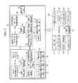
- FIG. 5is a block diagram showing an example in which a master device of FIG. 4 further includes a camera;
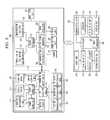
- FIG. 6is a block diagram showing an example in which a master manipulation module of
- FIG. 4further includes an RF reception node and a master device further includes an RF transmission node;
- FIG. 7is a block diagram showing an example in which the master device of FIG. 6 further includes a camera;
- FIG. 8is a block diagram showing an example in which the master manipulation module of FIG. 7 further includes a vibration motor and a motor drive unit;
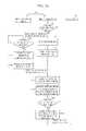
- FIG. 9is a flowchart showing operations of the respective components of the surgical robot system of FIG. 4 ;
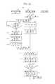
- FIG. 10is a flowchart showing operations of the respective components of the surgical robot system of FIG. 5 ;
- FIG. 11is a flowchart showing operations of the respective components of the surgical robot system of FIG. 6 ;
- FIG. 12is a flowchart showing operations of the respective components of the surgical robot system of FIG. 7 .
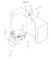
- FIG. 1is a view showing an outer appearance of a surgical robot system
- FIG. 2is a perspective view showing a master device of FIG. 1 in detail
- FIG. 3is a view showing a master manipulation module in detail
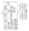
- FIG. 4is a schematic block diagram showing components of the surgical robot system.
- the surgical robot systemmay include a slave device 200 to perform surgery on a patient P who lies on an operating table, and a master device 100 to assist an operator S (e.g., a doctor) in remotely controlling the slave device 200 .
- an operator Se.g., a doctor
- at least one assistant Awho assists the operator S, may be located near the patient P.
- assisting the operator Smay refer to assisting surgery by the operator S in a space where the patient P is located.
- This assistancemay include an action such as changing used surgical instruments, for example, but is not limited thereto.
- various surgical instrumentsmay be used according to the kind of surgery and the number of robot arms 210 provided on the slave device 200 , and consequently, the number of surgical instruments used at once may be limited.
- the operator Smay instruct the assistant A near the patient P to change surgical instruments, and the assistant A may remove the surgical instrument 220 from the robot arm 210 of the slave device 200 according to the operator's instruction and may mount another surgical instrument 220 ′ placed on a tray to the corresponding robot arm 210 .
- the master device 100 and the slave device 200may be physically separate devices, without being in any way limited thereto. In one example, the master device 100 and the slave device 200 may be integrated with each other.
- the master device 100may include a master manipulation module 110 and a master control module 130 .
- the master manipulation module 110is manipulated by the operator S to generate a control signal for control of motion of surgical instruments 220 of the slave device 200 .
- the master manipulation module 110may include a manipulation tool T that the operator S grips for manipulation, and a pose recognizer attached to the manipulation tool T to acquire pose information on the manipulation tool T during movement of the manipulation tool T.
- pose informationmay include a position in a 3-Dimensional (3D) space as well as a pose.
- the master control module 130may serve to estimate a pose of the manipulation tool T based on pose information acquired via the aforementioned pose recognizer, generate a signal to control a pose of the surgical instruments 220 corresponding to the estimated pose, and transmit the control signal to the slave device 200 .
- the master manipulation module 110 and the master control module 130may be physically separate devices, without being in any way limited thereto.
- the operator Smay implement more convenient manipulation and be less limited with regard to a workspace.
- the master manipulation module 110 and the master control module 130may transmit and receive data via wireless communication.
- the master manipulation module 110 and the master control module 130may include RF transmission/reception units 116 and 134 respectively.
- the master manipulation module 110may further include a power source unit 112 to supply power to all components included in the master manipulation module 110 (see FIG. 4 ).
- the power source unit 112may include a battery, for example, without being in any way limited thereto.
- the master manipulation module 110may include the manipulation tool T having handles TH and a body TB, the pose recognizer provided at the manipulation tool T to acquire pose information on the manipulation tool T, the RF transmission/reception unit 116 that transmits and receives data to and from the master control module 130 in a wireless manner, and a first controller 111 that acquires pose information on the manipulation tool T via driving of the pose recognizer and transmits the acquired pose information to the master control module 130 through the RF transmission/reception unit 116 .
- the manipulation tool Tmay have the same shape as a surgical instrument that is used by a doctor in a conventional operating setting, without being in any way limited thereto.
- the surgical instrumentmay include a knife, scissors, forceps, a cautery, or tweezers, for example, without being in any way limited thereto.
- the master manipulation module 110may be constructed by mounting the pose recognizer, the RF transmission/reception unit 116 , and the first controller 111 to the manipulation tool T having the same shape as the aforementioned surgical instrument used in a conventional operating setting.
- the master manipulation module 110may be provided in the same number as the surgical instrument used in a conventional operating site.
- the operator Smay skillfully manipulate the manipulation tool T as if the operator were using a conventional surgical instrument, which enables intuitive manipulation and may reduce time required to be skillful in manipulation of the manipulation tool T.
- both master manipulation modules 110that the operator grips by both hands may have the same shape.
- the operator Smay grip and manipulate different shapes of master manipulation modules 110 by both hands respectively.
- the operator Smay grip and manipulate a scissors-shaped master manipulation module 110 by one hand and a knife-shaped manipulation module 110 by the other hand.
- two master manipulation modules 110are illustrated, the disclosure is not limited thereto. For example, only one master manipulation module 110 may be provided or three master manipulation modules 110 may be provided.
- an inertial measurement unit (IMU) 113may be used.
- the inertial measurement unit 113is comprised of a plurality of inertial sensors including an accelerometer and a gyroscope for measurement of angular velocity.
- the inertial measurement unit 113may be constructed in such a way that three accelerometers and three gyroscopes are orthogonally arranged.
- the inertial measurement unit 113 having the aforementioned configurationmay measure and output inertia data (hereinafter referred to as first pose information) depending on movement of an object to be measured.
- the first pose informationmay refer to information that may be used to estimate a first pose of the manipulation tool T.
- the inertial measurement unit 113may measure, e.g., movement inertia, rotational inertia, and geomagnetism of the object to be measured, and output first pose information on the object including various information, such as acceleration, velocity, orientation, and distance, for example.
- the first pose information output from the inertial measurement unit 113may be transmitted to the first controller 111 , and the first controller 111 may transmit the first pose information to the master control module 130 .
- the first controller 111may drive the inertial measurement unit 113 to acquire first pose information (e.g., acceleration, velocity, orientation, and distance) on the manipulation tool T, and transmit the acquired first pose information to the master control module 130 through the RF transmission/reception unit 116 .
- first pose informatione.g., acceleration, velocity, orientation, and distance
- the aforementioned pose recognizermay further include an RF reception node 117 .
- the master device 100may include a plurality of RF transmission nodes 150 as exemplarily shown in FIGS. 2 and 6 .
- the plurality of RF transmission nodes 150may include a first RF transmission node 151 , a second RF transmission node 152 , and a third RF transmission node 153 , which contain different identification information.
- FIGS. 2 and 6show the master device 100 as including three RF transmission nodes 150 , this is but one embodiment, and the number of RF transmission nodes is not in any way limited thereto.
- the RF transmission nodes 151 , 152 , and 153may have a triangular arrangement about the operator S, without being in any way limited thereto. With this arrangement of the RF transmission nodes 151 , 152 , and 153 , distances between the manipulation tool T and the respective RF transmission nodes 151 , 152 , and 153 may be calculated based on intensities of signals transmitted from the respective RF transmission nodes 151 , 152 , and 153 . As such, pose information on the manipulation tool T (hereinafter referred to as second pose information) may be easily acquired by subjecting the calculated distances to triangulation. The “second pose information” may be used later to estimate a third pose of the manipulation tool T.
- second pose informationmay be used later to estimate a third pose of the manipulation tool T.
- the first controller 111 of the master manipulation module 110may control the RF reception node 117 to request signal transmission of the respective RF transmission nodes 151 , 152 , and 153 , and may control the respective RF transmission nodes 151 , 152 , and 153 to transmit their own identification information to the RF reception node 117 when received the request from the RF reception node 117 . Thereafter, the first controller 111 may acquire second pose information on the manipulation tool T based on identification information per RF transmission node 151 , 152 , or 153 and signal intensity information transmitted from the RF reception node 117 , and transmit the acquired second pose information to the master control module 130 through the RF transmission/reception unit 116 .
- the aforementioned pose recognizermay include the inertial measurement unit 113 alone, or may include both the inertial measurement unit 113 and the RF reception node 117 . Provision of both the inertial measurement unit 113 and the RF reception node 117 may more advantageously correct error that may occur as measurement proceeds as compared to the case in which the inertial measurement unit 113 is used alone.
- the master manipulation module 110may further include at least one marker M attached to the manipulation tool T, and the master device 100 may further include a camera 170 to acquire an image of the manipulation tool T.
- the master control module 130may detect the marker M from the image of the manipulation tool T acquired via the camera 170 , and estimate a pose of the manipulation tool T (hereinafter referred to as a second pose) based on the detected marker M.
- the camera 170may be a depth camera, without being in any way limited thereto.
- the “depth camera”may refer to a camera that calculates a distance to an object (in the present embodiment, the manipulation tool T) by emitting laser or infrared light to the object and receiving the reflected light, thereby estimating depth information of the object.
- the depth cameramay advantageously acquire a high-resolution image and estimate a depth on a per pixel basis, and apply the acquired information to 3D model generation of a dynamic object or scene.
- the second pose of the manipulation tool Tmay be estimated based on the depth information of each marker M detected using the depth camera.
- the master modulation module 110may further include a motion sensor 115 attached to the manipulation tool T.
- the motion sensor 115serves to acquire motion information on the manipulation tool T.
- provision of the motion sensor 115may be limited to the manipulation tool T that mainly performs spreading and closing motions, for example, scissors and tweezers, without being in any way limited thereto.
- the manipulation tool Tsuch as scissors and tweezers, as exemplarily shown in FIG. 3 , may include a joint, and perform spreading and closing motions according to movement of the joint.
- motion informationinformation on motion of the joint
- the motion sensor 115may include a potentiometer, the present embodiment is not limited thereto, and other known motion sensors may be used.
- the first controller 111 of the master manipulation module 110may acquire motion information on the manipulation tool T by driving the motion sensor 115 attached to the joint of the manipulation tool T, and transmit the acquired motion information to the master control module 130 through the RF transmission/reception unit 116 .
- the master control module 130may estimate motion of the manipulation tool T based on the motion information transmitted from the master manipulation module 130 , generate a surgical instrument motion control signal corresponding to the estimated motion, and transmit the control signal to the slave device 200 .
- the master manipulation module 110may further include a contact sensor 114 provided at each handle TH of the manipulation tool T.
- the contact sensor 114serves to detect whether or not the operator S is manipulating the manipulation tool T, i.e. whether or not the operator S is gripping the manipulation tool T.
- an unexpected situationsuch as a situation that the operator S is not gripping the manipulation tool T or drops the manipulation tool T during surgery, occurs, no control signal corresponding to pose information and motion information on the manipulation tool T is transmitted to the slave device 200 , which may prevent accidents in an unexpected situation.
- the contact sensor 114may be attached to an inner wall of the handle TH that directly comes into contact with the hand of the operator S, a position of the contact sensor 114 is not in any way limited thereto and the contact sensor 114 may be provided anywhere so long as the contact sensor 114 may come into contact with the hand of the operator S.
- the contact sensor 114may be a sensor that detects contact based on capacitance variation, without being in any way limited thereto.
- the master manipulation module 110may further include a vibration motor 118 provided at the manipulation tool T, and a motor drive unit 119 to drive the vibration motor 118 .
- This configurationserves to inform the operator S of occurrence of a situation that the surgical instrument 220 of the slave device 200 collides with any internal organ or tissue during surgery.
- the first controller 111 of the master manipulation module 110drives the vibration motor 118 using the motor drive unit 119 upon receiving a signal indicating the aforementioned situation from the slave device 200 , thereby controlling the manipulation tool T to vibrate.
- the operator Smay sense a collision of the surgical instrument 220 of the slave device 200 .
- the master control module 130may include the RF transmission/reception unit 134 that transmits and receives data to and from the master manipulation module 110 in a wireless manner, a manipulation tool pose estimation unit 133 that estimates a pose of the manipulation tool T based on pose information on the manipulation tool T transmitted through the RF transmission/reception unit 134 , and a second controller 131 that determines whether or not the estimated pose is within a valid range, generates a surgical instrument pose control signal corresponding to the estimated pose if the estimated pose is within the valid range, and transmits the control signal to the slave device 200 .
- the “valid range”is a predetermined workspace range of the manipulation tool T. If the estimated pose deviates from the valid range, an abnormal manipulation situation is judged, and thus the surgical instrument pose control signal corresponding to the pose of the manipulation tool T is not generated.
- the master device 100may further include the camera 170 as described above, and the second controller 131 may detect the marker M from the image of the manipulation tool T acquired via the camera 170 , and estimate a pose of the manipulation tool T based on the detected marker M.
- the second controller 131 of the master control module 130may estimate a pose of the manipulation tool T based on pose information on the manipulation tool T transmitted from the master manipulation module 110 , or may estimate a pose of the manipulation tool T using the image acquired via the camera 170 .
- a pose of the manipulation tool T estimated based on pose information transmitted from the master manipulation module 110may be referred to as a first pose (i.e. a pose estimated based on first pose information acquired by the inertial measurement unit 113 ) or a third pose (i.e. a pose estimated based on second pose information acquired by the RF reception node 117 ), and a pose of the manipulation tool T estimated using the marker M detected from the image acquired via the camera 170 may be referred to as a second pose.
- the pose information on the manipulation tool T transmitted from the master manipulation module 110may include first pose information acquired via the inertial measurement unit 113 provided at the manipulation tool T and second pose information acquired via the RF reception node 117 .
- first pose informationacquired via the inertial measurement unit 113 provided at the manipulation tool T
- second pose informationacquired via the RF reception node 117 .
- only the first pose informationmay be transmitted, only the second pose information may be transmitted, or both the first pose information and the second pose information may be transmitted.
- the second controller 131may estimate a pose of the manipulation tool T (a first pose or a third pose) based on the transmitted only one unit of pose information.
- the second controller 131may estimate two poses, i.e. a first pose and a third pose of the manipulation tool T.
- the second controller 131may estimate a second pose of the manipulation tool T using the image acquired via the camera 170 .
- the aforementioned componentsmay be used alone, or may be combined with each other.
- a configuration including only the inertial measurement unit 113may be realized (see FIG. 4 )
- a configuration including the inertial measurement unit 113 , the marker M and the camera 170may be realized (see FIG. 5 )
- a configuration including the inertial measurement unit 113 , the RF reception node 117 and the RF transmission node 150may be realized (see FIG. 6 )
- a configuration including the marker M, the camera 170 , the RF reception node 117 and the RF transmission node 150may be realized (see FIG. 7 ).
- combination of two or more componentsmay ensure more accurate pose calculation via correction of error that may occur upon estimation of a pose of the manipulation tool T based on only one unit of pose information.
- the second controller 131may estimate a first pose of the manipulation tool T based on first pose information transmitted via the manipulation tool pose estimation unit 133 , determine whether or not the estimated first pose is within a valid range, generate a surgical instrument pose control signal corresponding to the estimated first pose using a control signal generator 135 if the first pose is within the valid range, and transmit the generated surgical instrument pose control signal to the slave device 200 through a communication unit 140 .
- the second controller 131may estimate a first pose of the manipulation tool T based on first pose information transmitted via the manipulation tool pose estimation unit 133 , and a second pose of the manipulation tool T based on depth information of the marker M detected from the image of the manipulation tool T acquired via the camera 170 . Thereafter, the second controller 131 may calculate a first final pose of the manipulation tool T by applying a predetermined weighting factor w to coordinates of each of the estimated first pose and second pose, determine whether or not the calculated first final pose is within a valid range, generate a surgical instrument pose control signal corresponding to the calculated first final pose using the control signal generator 135 if the first final pose is within the valid range, and transmit the generated surgical instrument pose control signal to the slave device 200 through the communication unit 140 .
- the second controller 131may estimate a first pose and a third pose of the manipulation tool T based on first pose information and second pose information transmitted via the manipulation tool pose estimation unit 133 . Thereafter, the second controller 131 may calculate a second final pose of the manipulation tool T by applying a predetermined weighting factor w to coordinates of each of the estimated first pose and third pose, determine whether or not the calculated second final pose is within a valid range, generate a surgical instrument pose control signal corresponding to the calculated second final pose using the control signal generator 135 if the second final pose is within the valid range, and transmit the generated surgical instrument pose control signal to the slave device 200 through the communication unit 140 .
- the second controller 131may estimate a first pose and a third pose of the manipulation tool T based on first pose information and second pose information transmitted via the manipulation tool pose estimation unit 133 , and additionally estimate a second pose of the manipulation tool T based on depth information of the marker M detected from the image of the manipulation tool T acquired via the camera 170 .
- the second controller 131may calculate a third final pose of the manipulation tool T by applying a predetermined weighting factor w to coordinates of each of the estimated first pose, second pose, and third pose, determine whether or not the calculated third final pose is within a valid range, generate a surgical instrument pose control signal corresponding to the calculated third final pose using the control signal generator 135 if the third final pose is within the valid range, and transmit the generated surgical instrument pose control signal to the slave device 200 through the communication unit 140 .
- the master control module 130may further include a manipulation tool motion estimation unit 132 to estimate motion of the manipulation tool T based on motion information transmitted from the master manipulation module 110 .
- the second controller 131may estimate motion of the manipulation tool T based on motion information transmitted from the master manipulation module 110 using the manipulation tool motion estimation unit 132 . Thereafter, the second controller 131 may generate a surgical instrument motion control signal corresponding to the estimated motion using the control signal generator 135 , and transmit the generated surgical instrument motion control signal to the slave device 200 through the communication unit 140 .
- the master device 100may further include a mode input unit 160 .
- the mode input unit 160serves to set a connection between the master device 100 and the slave device 200 .
- the mode input unit 160may take the form of a pedal, a switch, or a button, for example, without being in any way limited thereto.
- the mode input unit 160may be positioned so as to be manipulated by foot of the operator S because the operator S manipulates the master manipulation mode 110 by hand, but a position of the mode input unit 160 is not limited thereto.
- the master device 100 and the slave device 200may be set to a coupling mode, a decoupling mode, or an end mode, for example. Transmission of a control signal from the master device 100 to the slave device 200 may be accomplished only in the coupling mode.
- FIG. 9is a flowchart showing operations of the respective components of the surgical robot system of FIG. 4 according to an embodiment
- FIG. 10is a flowchart showing operations of the respective components of the surgical robot system of FIG. 5 according to an embodiment
- FIG. 11is a flowchart showing operations of the respective components of the surgical robot system of FIG. 6 according to an embodiment
- FIG. 12is a flowchart showing operations of the respective components of the surgical robot system of FIG. 7 according to an embodiment.
- the master control module 130transmits a signal to request the master manipulation module 110 of pose information and motion information on the manipulation tool T (operation S 903 ).
- the aforementioned request signalmay be transmitted in a wireless manner through the RF transmission/reception unit 134 .
- the master manipulation module 110determines whether or not the operator S is manipulating the manipulation tool T (operation S 905 ). If the operator S is manipulating the manipulation tool T, the master manipulation module 110 acquires first pose information on the manipulation tool T using the inertial measurement unit 113 attached to the manipulation tool T (operation S 907 ). In this case, whether or not the operator S is manipulating the manipulation tool T may be judged via the contact sensor 114 provided at each handle TH of the manipulation tool T, without being in any way limited thereto.
- the master manipulation module 110acquires motion information on the manipulation tool T using the motion sensor 115 provided at the joint of the manipulation tool T (operation S 909 ), and thereafter transmits first pose information on the manipulation tool T acquired in operation S 907 as well as the acquired motion information to the master control module 130 (operation S 911 ).
- the master control module 130estimates a first pose and motion of the manipulation tool T based on the first pose information and motion information transmitted from the master manipulation module 110 (operation S 913 ), and determines whether or not the estimated first pose is within a valid range (operation S 915 ). If the judged result shows that the first pose is within the valid range, the master control module 130 generates a surgical instrument pose control signal and a surgical instrument motion control signal corresponding respectively to the estimated first pose and motion (operation S 917 ), and transmits the surgical instrument pose control signal and the surgical instrument motion control signal to the slave device 200 (operation S 919 ).
- the “valid range”may be a predetermined workspace range of the manipulation tool T, for example.
- whether or not the master control module 130 and the slave device 200 are in a coupling modeis judged (operation S 1001 ). If the coupling mode is judged, the master control module 130 requests the master manipulation module 110 of pose information and motion information on the manipulation tool T (operation S 1003 ), detects the marker M from the image of the manipulation tool T acquired via the camera 170 (operation S 1013 ), and estimates a second pose of the manipulation tool T based on depth information of the detected marker M (operation S 1015 ).
- the master manipulation module 110determines whether or not the operator S is manipulating the manipulation tool T (operation S 1005 ). If the operator S is manipulating the manipulation tool T, the master manipulation module 110 acquires first pose information on the manipulation tool T using the inertial measurement unit 113 attached to the manipulation tool T (operation S 1007 ). In this case, whether or not the operator S is manipulating the manipulation tool T may be judged via the contact sensor 114 provided at each handle TH of the manipulation tool T, without being in any way limited thereto.
- the master manipulation module 110acquires motion information on the manipulation tool T using the motion sensor 115 provided at the joint of the manipulation tool T (operation S 1009 ), and thereafter transmits first pose information on the manipulation tool T acquired in operation S 1007 as well as the acquired motion information to the master control module 130 (operation S 1011 ).
- the master control module 130estimates a first pose and motion of the manipulation tool T based on the first pose information and motion information transmitted from the master manipulation module 110 (operation S 1017 ), calculates a first final pose of the manipulation tool T by applying a predetermined weighting factor w to coordinates of each of the estimated first pose and the second pose estimated in operation S 1015 (operation S 1019 ), determines whether or not the calculated first final pose is within a valid range (operation S 1021 ), generates a surgical instrument pose control signal and a surgical instrument motion control signal corresponding respectively to the calculated first final pose and the estimated motion if the first final pose is within the valid range (operation S 1023 ), and transmits the surgical instrument pose control signal and the surgical instrument motion control signal to the slave device 200 (operation S 1025 ).
- the master control module 130transmits a signal to request the master manipulation module 110 of pose information and motion information on the manipulation tool T (operation S 1103 ).
- the aforementioned request signalmay be transmitted in a wireless manner through the RF transmission/reception unit 134 .
- the master manipulation module 110determines whether or not the operator S is manipulating the manipulation tool T (operation S 1105 ). If the operator S is manipulating the manipulation tool T, the master manipulation module 110 acquires first pose information on the manipulation tool T using the inertial measurement unit 113 attached to the manipulation tool T (operation S 1107 ), and acquires second pose information on the manipulation tool T using the RF reception node 117 provided at the manipulation tool T and the RF transmission node 150 provided near the operator S (operation S 1109 ).
- the master manipulation module 110acquires motion information on the manipulation tool T using the motion sensor 115 provided at the joint of the manipulation tool T (operation S 1111 ), and transmits the acquired motion information as well as the first pose information and the second pose information acquired respectively in operation S 1107 and operation S 1109 to the master control module 130 (operation S 1113 ).
- the master control module 130estimates a first pose, a third pose, and motion of the manipulation tool T based on the first pose information, the second pose information, and motion information transmitted from the master manipulation module 110 (operation S 1115 ), and calculates a second final pose of the manipulation tool T by applying a predetermined weighting factor w to coordinates of each of the estimated first pose and third pose (operation S 1117 ).
- the master control module 130determines whether or not the calculated second final pose is within a valid range (operation S 1119 ), generates a surgical instrument pose control signal and a surgical instrument motion control signal corresponding respectively to the calculated second final pose and the estimated motion if the second final pose is within the valid range (operation S 1121 ), and transmits the surgical instrument pose control signal and the surgical instrument motion control signal to the slave device 200 (operation S 1123 ).
- whether or not the master control module 130 and the slave device 200 are in a coupling modeis judged (operation S 1201 ). If the coupling mode is judged, the master control module 130 requests the master manipulation module 110 of pose information and motion information on the manipulation tool T (operation S 1203 ), detects the marker M from the image of the manipulation tool T acquired via the camera 170 (operation S 1215 ), and estimates a second pose of the manipulation tool T based on depth information of the detected marker M (operation S 1217 ).
- the master manipulation module 110which has received the signal to request for pose information and motion information from the master control module 130 , acquires first pose information on the manipulation tool T using the inertial measurement unit 113 attached to the manipulation tool T (operation S 1207 ), acquires second pose information on the manipulation tool T using the RF reception node 117 provided at the manipulation tool T and the RF transmission node 150 provided near the operator S (operation S 1209 ), acquires motion information on the manipulation tool T using the motion sensor 115 provided at the joint of the manipulation tool T (operation S 1211 ), and transmits the acquired motion information as well as the first pose information and the second pose information acquired respectively in operation S 1207 and S 1209 to the master control module 130 (operation S 1213 ).
- the master control module 130estimates a first pose, a third pose, and motion of the manipulation tool T based on the first pose information, the second pose information, and motion information transmitted from the master manipulation module 110 (operation S 1219 ), calculates a third final pose of the manipulation tool T by applying a predetermined weighting factor w to coordinates of each of the estimated first pose and third pose as well as the second pose estimated in operation S 1217 (operation S 1221 ), determines whether or not the calculated third final pose is within a valid range (operation S 1223 ), generates a surgical instrument pose control signal and a surgical instrument motion control signal corresponding respectively to the calculated third final pose and the estimated motion if the third final pose is within the valid range (operation S 1225 ), and transmits the surgical instrument pose control signal and the surgical instrument motion control signal to the slave device 200 (operation S 1227 ).
- any one configurationmay be used alone, two or more configurations may be combined with one another, which may ensure more accurate estimation of a pose of the manipulation tool T via correction of error that may occur when adopting only one configuration.
- the master device 100may further include the communication unit 140 .
- the communication unit 140serves to transmit and receive data between the master device 100 and the slave device 200 , and may perform wired communication, wireless communication, or a combination thereof.
- the master device 100may further include a display unit 120 .
- the display unit 120may display an image of the interior of the patient's body collected via an endoscope 230 of the slave device 200 , and a 3D virtual image acquired using medical images of the patient P before surgery.
- the master device 100may include an image processor 136 that receives and processes image data transmitted from the slave device 200 to output the image data to the display unit 120 .
- the “image data”, as described above,may include an image of the interior of the patient's body collected via the endoscope 230 and a 3D virtual image acquired using medical images of the patient before surgery, without being in any way limited thereto.
- the display unit 120may include a Liquid Crystal Display (LCD), a Light Emitting Diode (LED) display, a transparent display, a hologram display, or a Head Mounted Display (HMD), for example, without being in any way limited thereto.
- LCDLiquid Crystal Display
- LEDLight Emitting Diode
- HMDHead Mounted Display
- an augmented reality image generated by composing the manipulation tool T that is being manipulated by the operator S over a corresponding position of the actual image of the interior of the patient's body collected via the endoscope 230may be displayed on the display unit 120 .
- the operator Smay intuitively manipulate the manipulation tool T as if the operator were directly performing surgery.
- the display unit 120may display information regarding operation of the slave device 200 as well as patient information, for example.
- the “patient information”may be information indicating the state of the patient P, such as patient vital signs, such as body-temperature, pulse, respiration-rate, blood-pressure, for example.
- the slave device 200that will be described hereinafter may further include a vital sign measurement unit including a body-temperature measurement module, a pulse measurement module, a respiration-rate measurement module, a blood-pressure measurement module, etc.
- the master device 100may further include a signal processor (not shown) that receives and processes vital signs transmitted from the slave device 200 to output the processed vital signs to the display unit 120 .
- the slave device 200may include a plurality of robot arms 210 , and various surgical instruments 220 mounted at ends of the respective robot arms 210 .
- the plurality of robot arms 210may be coupled to a main body 201 to be fixed to and supported by the main body 201 .
- the number of the surgical instruments 220 that are used at once as well as the number of the robot arms 210may depend on various factors, such as diagnostic methods, surgical methods, and spatial restrictions of an operating room.
- Each of the plurality of robot arms 210may include a plurality of links 211 and a plurality of joints 213 .
- Each joint 213may connect the two links 211 to each other and may have 1 degree of freedom (DOF) or more.
- DOFrefers to a DOF with regard to kinematics or inverse kinematics, i.e. the DOF of a device.
- the DOF of a devicerefers to the number of independent motions of a device, or the number of variables that determine independent motions at relative positions between links.
- an object in a 3D space defined by X-, Y-, and Z-axeshas one or more of 3 DOF to determine a spatial position of the object (a position on each axis), 3 DOF to determine a spatial pose of the object (a position on each axis), and 3 DOF to determine a spatial orientation of the object (a rotation angle relative to each axis). More specifically, it will be appreciated that the object has 6 DOF if an object is movable along each of X-, Y- and Z-axes and is rotatable about each of X-, Y- and Z-axes.
- Each joint 213may be provided with a detector to detect information regarding the state of the joint 213 .
- the detectormay include a force/torque detector to detect information regarding force/torque applied to the joint 213 , a position detector to detect information regarding a position of the joint 213 , and a speed detector to detect information regarding a movement speed of the joint 213 .
- the speed detectormay be omitted according to the kind of a position sensor that is used as the position detector.
- Each joint of the robot arm 210may be provided with a first drive unit 215 to control movement of the robot arm 210 in response to a surgical instrument pose control signal transmitted from the master device 100 .
- a surgical instrument pose control signaltransmitted from the master device 100 .
- the first controller 111 of the master manipulation module 110acquires pose information on the manipulation tool T to transmit the acquired pose information to the master control module 130 .
- the master control module 130generates a surgical instrument pose control signal corresponding to the transmitted pose information to transmit the control signal to the slave device 200 via a communication unit 260 .
- the controller 240 of the slave device 200drives the first drive unit 215 in response to the surgical instrument pose control signal transmitted from the master device 100 , thereby controlling movement of each joint of the robot arm 210 and moving the surgical instrument 220 mounted to the robot arm 210 to hold a corresponding pose.
- a practical procedure of controlling rotation and movement of the robot arm 210 in a given direction in response to the surgical instrument pose control signaldeviates somewhat from the substance of the disclosure, and thus a detailed description thereof will be omitted herein.
- each joint of the robot arm 210 of the slave device 200may be moved in response to a control signal transmitted from the master device 100 , the joint may be moved by external force. That is, the assistant A located near an operating table may manually move each joint of the robot arm 210 to control, e.g., a pose of the surgical instrument 220 .
- each surgical instrument 220may include a housing mounted to the end of the robot arm 210 , a shaft extending from the housing by a predetermined length, and an end effector coupled to a distal end of the shaft.
- the surgical instruments 220may be classified into main surgical instruments and auxiliary surgical instruments.
- the “main surgical instrument”may refer to an instrument including an end effector (e.g., a knife or a surgical needle) that performs direct surgical motion, such as, e.g., cutting, suturing, clotting, or washing, on a surgical region.
- the “auxiliary surgical instrument”may refer to an instrument including an end effector (e.g., a skin holder) that does not perform direct motion on a surgical region and assists motion of the main surgical instrument.
- the end effectoris a part of the surgical instrument 220 that practically acts on a surgical region of the patient P.
- the end effectormay include a skin holder, suction line, knife, scissors, grasper, surgical needle, staple applier, needle holder, scalpel, cutting blade, etc., without being in any way limited thereto. Any other known instruments required for surgery may be used.
- a drive wheelmay be coupled to the housing and connected to the end effector via a wire, for example.
- the end effectormay be operated via rotation of the drive wheel.
- a second drive unit 225 to rotate the drive wheelmay be provided at the end of the robot arm 210 .
- the first controller 111 of the master manipulation module 110acquires motion information on the manipulation tool T to transmit the information to the master control module 130 , and the master control module 130 generates a surgical instrument motion control signal corresponding to motion information transmitted from the master control module 130 to transmit the control signal to the slave device 200 .
- a mechanism to operate the end effectoris not limited to the aforementioned configuration and various electrical/mechanical mechanisms may naturally be applied to realize motion of the end effector required for robotic surgery.
- the endoscope 230 of the slave device 200serves to assist motion of a main surgical instrument rather than directly performing surgical motion on a surgical region.
- the endoscope 230corresponds to an auxiliary surgical instrument in a broad sense.
- the endoscope 230may be selected from among various surgical endoscopes, such as a thoracoscope, arthroscope, rhinoscope, cystoscope, proctoscope, duodenoscope, and cardioscope, for example, in addition to a celioscope that is mainly used in robotic surgery.
- the endoscope 230may be a Complementary Metal Oxide Semiconductor (CMOS) camera or a Charge Coupled Device (CCD) camera, without being in any way limited thereto.
- CMOSComplementary Metal Oxide Semiconductor
- CCDCharge Coupled Device
- the endoscope 230may include a lighting device (not shown) to emit light to a surgical region.
- the endoscope 230may be mounted to the end of the robot arm 210 as exemplarily shown in FIG. 1 , and the slave device 200 may further include a third drive unit 235 to operate the endoscope 230 .
- the controller 240 of the slave device 200may transmit an image of the interior of the patient's body collected via the endoscope 230 to the master device 100 .
- the slave device 200may further include a display unit 250 to display an image of the interior of the patient's body collected via the endoscope 230 .
- the controller 240 of the slave device 200may include an image processor 241 that processes an image collected via the endoscope 230 to output the processed image to the display unit 250 .
- the controller 240 of the slave device 200may transmit a signal indicating occurrence of collision to the master device 100 .
- the above-described embodimentsmay be recorded in computer-readable media including program instructions to implement various operations embodied by a computer.
- the mediamay also include, alone or in combination with the program instructions, data files, data structures, and the like.
- the program instructions recorded on the mediamay be those specially designed and constructed for the purposes of embodiments, or they may be of the kind well-known and available to those having skill in the computer software arts.
- Examples of computer-readable mediainclude magnetic media such as hard disks, floppy disks, and magnetic tape; optical media such as CD ROM disks and DVDs; magneto-optical media such as optical disks; and hardware devices that are specially configured to store and perform program instructions, such as read-only memory (ROM), random access memory (RAM), flash memory, and the like.
- the computer-readable mediamay also be a distributed network, so that the program instructions are stored and executed in a distributed fashion.
- the program instructionsmay be executed by one or more processors.
- the computer-readable mediamay also be embodied in at least one application specific integrated circuit (ASIC) or Field Programmable Gate Array (FPGA), which executes (processes like a processor) program instructions.
- ASICapplication specific integrated circuit
- FPGAField Programmable Gate Array
- Examples of program instructionsinclude both machine code, such as produced by a compiler, and files containing higher level code that may be executed by the computer using an interpreter.
- the above-described devicesmay be configured to act as one or more software modules in order to perform the operations of the above-described embodiments, or vice versa.
Landscapes
- Health & Medical Sciences (AREA)
- Life Sciences & Earth Sciences (AREA)
- Engineering & Computer Science (AREA)
- Surgery (AREA)
- Nuclear Medicine, Radiotherapy & Molecular Imaging (AREA)
- Medical Informatics (AREA)
- Public Health (AREA)
- Heart & Thoracic Surgery (AREA)
- Robotics (AREA)
- Molecular Biology (AREA)
- Animal Behavior & Ethology (AREA)
- General Health & Medical Sciences (AREA)
- Biomedical Technology (AREA)
- Veterinary Medicine (AREA)
- Oral & Maxillofacial Surgery (AREA)
- Pathology (AREA)
- Gynecology & Obstetrics (AREA)
- Radiology & Medical Imaging (AREA)
- Manipulator (AREA)
Abstract
Description
Claims (20)
Applications Claiming Priority (2)
| Application Number | Priority Date | Filing Date | Title |
|---|---|---|---|
| KR10-2013-0037938 | 2013-04-08 | ||
| KR1020130037938AKR20140121581A (en) | 2013-04-08 | 2013-04-08 | Surgical robot system |
Publications (2)
| Publication Number | Publication Date |
|---|---|
| US20140303643A1 US20140303643A1 (en) | 2014-10-09 |
| US9439733B2true US9439733B2 (en) | 2016-09-13 |
Family
ID=51654977
Family Applications (1)
| Application Number | Title | Priority Date | Filing Date |
|---|---|---|---|
| US14/030,302Expired - Fee RelatedUS9439733B2 (en) | 2013-04-08 | 2013-09-18 | Surgical robot system |
Country Status (2)
| Country | Link |
|---|---|
| US (1) | US9439733B2 (en) |
| KR (1) | KR20140121581A (en) |
Cited By (29)
| Publication number | Priority date | Publication date | Assignee | Title |
|---|---|---|---|---|
| US9898937B2 (en) | 2012-09-28 | 2018-02-20 | Applied Medical Resources Corporation | Surgical training model for laparoscopic procedures |
| US9922579B2 (en) | 2013-06-18 | 2018-03-20 | Applied Medical Resources Corporation | Gallbladder model |
| US9940849B2 (en) | 2013-03-01 | 2018-04-10 | Applied Medical Resources Corporation | Advanced surgical simulation constructions and methods |
| US9959786B2 (en) | 2012-09-27 | 2018-05-01 | Applied Medical Resources Corporation | Surgical training model for laparoscopic procedures |
| US20180168759A1 (en)* | 2015-04-23 | 2018-06-21 | Sri International | Hyperdexterous surgical system user interface devices |
| US10081727B2 (en) | 2015-05-14 | 2018-09-25 | Applied Medical Resources Corporation | Synthetic tissue structures for electrosurgical training and simulation |
| US10121391B2 (en) | 2012-09-27 | 2018-11-06 | Applied Medical Resources Corporation | Surgical training model for laparoscopic procedures |
| US10140889B2 (en) | 2013-05-15 | 2018-11-27 | Applied Medical Resources Corporation | Hernia model |
| US10198965B2 (en) | 2012-08-03 | 2019-02-05 | Applied Medical Resources Corporation | Simulated stapling and energy based ligation for surgical training |
| US10198966B2 (en) | 2013-07-24 | 2019-02-05 | Applied Medical Resources Corporation | Advanced first entry model for surgical simulation |
| US10223936B2 (en) | 2015-06-09 | 2019-03-05 | Applied Medical Resources Corporation | Hysterectomy model |
| US10332425B2 (en) | 2015-07-16 | 2019-06-25 | Applied Medical Resources Corporation | Simulated dissectible tissue |
| US10354556B2 (en) | 2015-02-19 | 2019-07-16 | Applied Medical Resources Corporation | Simulated tissue structures and methods |
| US10395559B2 (en) | 2012-09-28 | 2019-08-27 | Applied Medical Resources Corporation | Surgical training model for transluminal laparoscopic procedures |
| US10490105B2 (en) | 2015-07-22 | 2019-11-26 | Applied Medical Resources Corporation | Appendectomy model |
| US10535281B2 (en) | 2012-09-26 | 2020-01-14 | Applied Medical Resources Corporation | Surgical training model for laparoscopic procedures |
| US10657845B2 (en) | 2013-07-24 | 2020-05-19 | Applied Medical Resources Corporation | First entry model |
| US10679520B2 (en) | 2012-09-27 | 2020-06-09 | Applied Medical Resources Corporation | Surgical training model for laparoscopic procedures |
| US10706743B2 (en) | 2015-11-20 | 2020-07-07 | Applied Medical Resources Corporation | Simulated dissectible tissue |
| US10720084B2 (en) | 2015-10-02 | 2020-07-21 | Applied Medical Resources Corporation | Hysterectomy model |
| US10796606B2 (en) | 2014-03-26 | 2020-10-06 | Applied Medical Resources Corporation | Simulated dissectible tissue |
| US10818201B2 (en) | 2014-11-13 | 2020-10-27 | Applied Medical Resources Corporation | Simulated tissue models and methods |
| US10847057B2 (en) | 2017-02-23 | 2020-11-24 | Applied Medical Resources Corporation | Synthetic tissue structures for electrosurgical training and simulation |
| US10854112B2 (en) | 2010-10-01 | 2020-12-01 | Applied Medical Resources Corporation | Portable laparoscopic trainer |
| US11030922B2 (en) | 2017-02-14 | 2021-06-08 | Applied Medical Resources Corporation | Laparoscopic training system |
| US11120708B2 (en) | 2016-06-27 | 2021-09-14 | Applied Medical Resources Corporation | Simulated abdominal wall |
| US11158212B2 (en) | 2011-10-21 | 2021-10-26 | Applied Medical Resources Corporation | Simulated tissue structure for surgical training |
| WO2022002159A1 (en)* | 2020-07-01 | 2022-01-06 | 北京术锐技术有限公司 | Master-slave motion control method, robot system, device, and storage medium |
| US11403968B2 (en) | 2011-12-20 | 2022-08-02 | Applied Medical Resources Corporation | Advanced surgical simulation |
Families Citing this family (146)
| Publication number | Priority date | Publication date | Assignee | Title |
|---|---|---|---|---|
| US8219178B2 (en) | 2007-02-16 | 2012-07-10 | Catholic Healthcare West | Method and system for performing invasive medical procedures using a surgical robot |
| US10893912B2 (en) | 2006-02-16 | 2021-01-19 | Globus Medical Inc. | Surgical tool systems and methods |
| US10653497B2 (en) | 2006-02-16 | 2020-05-19 | Globus Medical, Inc. | Surgical tool systems and methods |
| US10357184B2 (en) | 2012-06-21 | 2019-07-23 | Globus Medical, Inc. | Surgical tool systems and method |
| US9308050B2 (en) | 2011-04-01 | 2016-04-12 | Ecole Polytechnique Federale De Lausanne (Epfl) | Robotic system and method for spinal and other surgeries |
| US11857266B2 (en) | 2012-06-21 | 2024-01-02 | Globus Medical, Inc. | System for a surveillance marker in robotic-assisted surgery |
| US12310683B2 (en) | 2012-06-21 | 2025-05-27 | Globus Medical, Inc. | Surgical tool systems and method |
| US10624710B2 (en) | 2012-06-21 | 2020-04-21 | Globus Medical, Inc. | System and method for measuring depth of instrumentation |
| US10350013B2 (en) | 2012-06-21 | 2019-07-16 | Globus Medical, Inc. | Surgical tool systems and methods |
| US11864745B2 (en) | 2012-06-21 | 2024-01-09 | Globus Medical, Inc. | Surgical robotic system with retractor |
| US11395706B2 (en) | 2012-06-21 | 2022-07-26 | Globus Medical Inc. | Surgical robot platform |
| US11607149B2 (en) | 2012-06-21 | 2023-03-21 | Globus Medical Inc. | Surgical tool systems and method |
| US11298196B2 (en) | 2012-06-21 | 2022-04-12 | Globus Medical Inc. | Surgical robotic automation with tracking markers and controlled tool advancement |
| US11317971B2 (en) | 2012-06-21 | 2022-05-03 | Globus Medical, Inc. | Systems and methods related to robotic guidance in surgery |
| US12262954B2 (en) | 2012-06-21 | 2025-04-01 | Globus Medical, Inc. | Surgical robotic automation with tracking markers |
| EP2863827B1 (en) | 2012-06-21 | 2022-11-16 | Globus Medical, Inc. | Surgical robot platform |
| US11116576B2 (en) | 2012-06-21 | 2021-09-14 | Globus Medical Inc. | Dynamic reference arrays and methods of use |
| US12004905B2 (en) | 2012-06-21 | 2024-06-11 | Globus Medical, Inc. | Medical imaging systems using robotic actuators and related methods |
| US10136954B2 (en) | 2012-06-21 | 2018-11-27 | Globus Medical, Inc. | Surgical tool systems and method |
| US11045267B2 (en) | 2012-06-21 | 2021-06-29 | Globus Medical, Inc. | Surgical robotic automation with tracking markers |
| US11974822B2 (en) | 2012-06-21 | 2024-05-07 | Globus Medical Inc. | Method for a surveillance marker in robotic-assisted surgery |
| US11253327B2 (en) | 2012-06-21 | 2022-02-22 | Globus Medical, Inc. | Systems and methods for automatically changing an end-effector on a surgical robot |
| US11399900B2 (en) | 2012-06-21 | 2022-08-02 | Globus Medical, Inc. | Robotic systems providing co-registration using natural fiducials and related methods |
| US12220120B2 (en) | 2012-06-21 | 2025-02-11 | Globus Medical, Inc. | Surgical robotic system with retractor |
| US11864839B2 (en) | 2012-06-21 | 2024-01-09 | Globus Medical Inc. | Methods of adjusting a virtual implant and related surgical navigation systems |
| US11857149B2 (en) | 2012-06-21 | 2024-01-02 | Globus Medical, Inc. | Surgical robotic systems with target trajectory deviation monitoring and related methods |
| US10231791B2 (en) | 2012-06-21 | 2019-03-19 | Globus Medical, Inc. | Infrared signal based position recognition system for use with a robot-assisted surgery |
| US12329593B2 (en) | 2012-06-21 | 2025-06-17 | Globus Medical, Inc. | Surgical robotic automation with tracking markers |
| US10758315B2 (en) | 2012-06-21 | 2020-09-01 | Globus Medical Inc. | Method and system for improving 2D-3D registration convergence |
| US20150032164A1 (en) | 2012-06-21 | 2015-01-29 | Globus Medical, Inc. | Methods for Performing Invasive Medical Procedures Using a Surgical Robot |
| US11793570B2 (en) | 2012-06-21 | 2023-10-24 | Globus Medical Inc. | Surgical robotic automation with tracking markers |
| JP6053358B2 (en)* | 2012-07-03 | 2016-12-27 | オリンパス株式会社 | Surgery support device |
| KR101997566B1 (en)* | 2012-08-07 | 2019-07-08 | 삼성전자주식회사 | Surgical robot system and control method thereof |
| US9283048B2 (en) | 2013-10-04 | 2016-03-15 | KB Medical SA | Apparatus and systems for precise guidance of surgical tools |
| US9241771B2 (en) | 2014-01-15 | 2016-01-26 | KB Medical SA | Notched apparatus for guidance of an insertable instrument along an axis during spinal surgery |
| WO2015121311A1 (en) | 2014-02-11 | 2015-08-20 | KB Medical SA | Sterile handle for controlling a robotic surgical system from a sterile field |
| EP3134022B1 (en) | 2014-04-24 | 2018-01-10 | KB Medical SA | Surgical instrument holder for use with a robotic surgical system |
| US10357257B2 (en) | 2014-07-14 | 2019-07-23 | KB Medical SA | Anti-skid surgical instrument for use in preparing holes in bone tissue |
| EP3226781B1 (en) | 2014-12-02 | 2018-08-01 | KB Medical SA | Robot assisted volume removal during surgery |
| DE102014226239A1 (en)* | 2014-12-17 | 2016-06-23 | Kuka Roboter Gmbh | Method for the safe coupling of an input device |
| US20160206179A1 (en)* | 2015-01-15 | 2016-07-21 | National Taiwan University | Assistive robot endoscopic system with intuitive maneuverability for laparoscopic surgery and method thereof |
| US10013808B2 (en) | 2015-02-03 | 2018-07-03 | Globus Medical, Inc. | Surgeon head-mounted display apparatuses |
| WO2016131903A1 (en) | 2015-02-18 | 2016-08-25 | KB Medical SA | Systems and methods for performing minimally invasive spinal surgery with a robotic surgical system using a percutaneous technique |
| US10058394B2 (en) | 2015-07-31 | 2018-08-28 | Globus Medical, Inc. | Robot arm and methods of use |
| US10646298B2 (en) | 2015-07-31 | 2020-05-12 | Globus Medical, Inc. | Robot arm and methods of use |
| US10080615B2 (en) | 2015-08-12 | 2018-09-25 | Globus Medical, Inc. | Devices and methods for temporary mounting of parts to bone |
| WO2017033365A1 (en)* | 2015-08-25 | 2017-03-02 | 川崎重工業株式会社 | Remote control robot system |
| JP6894431B2 (en) | 2015-08-31 | 2021-06-30 | ケービー メディカル エスアー | Robotic surgical system and method |
| US10034716B2 (en) | 2015-09-14 | 2018-07-31 | Globus Medical, Inc. | Surgical robotic systems and methods thereof |
| US9771092B2 (en) | 2015-10-13 | 2017-09-26 | Globus Medical, Inc. | Stabilizer wheel assembly and methods of use |
| KR102462799B1 (en)* | 2015-11-05 | 2022-11-03 | 삼성전자주식회사 | Method and apparatus for estimating pose |
| US10646289B2 (en) | 2015-12-29 | 2020-05-12 | Koninklijke Philips N.V. | System, controller and method using virtual reality device for robotic surgery |
| US11058378B2 (en) | 2016-02-03 | 2021-07-13 | Globus Medical, Inc. | Portable medical imaging system |
| US10448910B2 (en) | 2016-02-03 | 2019-10-22 | Globus Medical, Inc. | Portable medical imaging system |
| US10842453B2 (en) | 2016-02-03 | 2020-11-24 | Globus Medical, Inc. | Portable medical imaging system |
| US11883217B2 (en) | 2016-02-03 | 2024-01-30 | Globus Medical, Inc. | Portable medical imaging system and method |
| US10117632B2 (en) | 2016-02-03 | 2018-11-06 | Globus Medical, Inc. | Portable medical imaging system with beam scanning collimator |
| BR112018009251A2 (en) | 2016-02-05 | 2019-04-09 | Board Of Regents Of The University Of Texas System | surgical apparatus and customized main controller for a surgical apparatus |
| KR102708262B1 (en) | 2016-02-05 | 2024-09-20 | 보드 오브 리전츠, 더 유니버시티 오브 텍사스 시스템 | The manipulatable intraruminal medical device |
| US10866119B2 (en) | 2016-03-14 | 2020-12-15 | Globus Medical, Inc. | Metal detector for detecting insertion of a surgical device into a hollow tube |
| US10786323B2 (en)* | 2016-03-23 | 2020-09-29 | Nanyang Technological University | Handheld surgical instrument, surgical tool system, methods of forming and operating the same |
| EP3241518B1 (en) | 2016-04-11 | 2024-10-23 | Globus Medical, Inc | Surgical tool systems |
| EP3236211A1 (en)* | 2016-04-21 | 2017-10-25 | Thomson Licensing | Method and apparatus for estimating a pose of a rendering device |
| US11382649B2 (en) | 2016-11-17 | 2022-07-12 | Covidien Lp | Rotation control systems for surgical instruments |
| JP7233841B2 (en) | 2017-01-18 | 2023-03-07 | ケービー メディカル エスアー | Robotic Navigation for Robotic Surgical Systems |
| US11071594B2 (en) | 2017-03-16 | 2021-07-27 | KB Medical SA | Robotic navigation of robotic surgical systems |
| US11135015B2 (en) | 2017-07-21 | 2021-10-05 | Globus Medical, Inc. | Robot surgical platform |
| US11357548B2 (en) | 2017-11-09 | 2022-06-14 | Globus Medical, Inc. | Robotic rod benders and related mechanical and motor housings |
| US11794338B2 (en) | 2017-11-09 | 2023-10-24 | Globus Medical Inc. | Robotic rod benders and related mechanical and motor housings |
| EP3492032B1 (en) | 2017-11-09 | 2023-01-04 | Globus Medical, Inc. | Surgical robotic systems for bending surgical rods |
| US11134862B2 (en) | 2017-11-10 | 2021-10-05 | Globus Medical, Inc. | Methods of selecting surgical implants and related devices |
| KR101993410B1 (en)* | 2017-11-16 | 2019-06-26 | 전자부품연구원 | Robot control system and apparatus using vibration feedback |
| US20190254753A1 (en) | 2018-02-19 | 2019-08-22 | Globus Medical, Inc. | Augmented reality navigation systems for use with robotic surgical systems and methods of their use |
| US10573023B2 (en) | 2018-04-09 | 2020-02-25 | Globus Medical, Inc. | Predictive visualization of medical imaging scanner component movement |
| US11553938B2 (en) | 2018-05-03 | 2023-01-17 | Covidien Lp | Surgical instruments, control assemblies, and surgical systems facilitating manipulation and visualization |
| US11337742B2 (en) | 2018-11-05 | 2022-05-24 | Globus Medical Inc | Compliant orthopedic driver |
| US11278360B2 (en) | 2018-11-16 | 2022-03-22 | Globus Medical, Inc. | End-effectors for surgical robotic systems having sealed optical components |
| US11744655B2 (en) | 2018-12-04 | 2023-09-05 | Globus Medical, Inc. | Drill guide fixtures, cranial insertion fixtures, and related methods and robotic systems |
| US11602402B2 (en) | 2018-12-04 | 2023-03-14 | Globus Medical, Inc. | Drill guide fixtures, cranial insertion fixtures, and related methods and robotic systems |
| KR102221090B1 (en)* | 2018-12-18 | 2021-02-26 | (주)미래컴퍼니 | User interface device, master console for surgical robot apparatus and operating method of master console |
| WO2020185797A1 (en)* | 2019-03-14 | 2020-09-17 | Covidien Lp | Instrument drive unit torque compensation using inertial measurement unit |
| US11918313B2 (en) | 2019-03-15 | 2024-03-05 | Globus Medical Inc. | Active end effectors for surgical robots |
| US11382549B2 (en) | 2019-03-22 | 2022-07-12 | Globus Medical, Inc. | System for neuronavigation registration and robotic trajectory guidance, and related methods and devices |
| US11806084B2 (en) | 2019-03-22 | 2023-11-07 | Globus Medical, Inc. | System for neuronavigation registration and robotic trajectory guidance, and related methods and devices |
| US11317978B2 (en) | 2019-03-22 | 2022-05-03 | Globus Medical, Inc. | System for neuronavigation registration and robotic trajectory guidance, robotic surgery, and related methods and devices |
| US20200297357A1 (en) | 2019-03-22 | 2020-09-24 | Globus Medical, Inc. | System for neuronavigation registration and robotic trajectory guidance, robotic surgery, and related methods and devices |
| US11571265B2 (en) | 2019-03-22 | 2023-02-07 | Globus Medical Inc. | System for neuronavigation registration and robotic trajectory guidance, robotic surgery, and related methods and devices |
| US11419616B2 (en) | 2019-03-22 | 2022-08-23 | Globus Medical, Inc. | System for neuronavigation registration and robotic trajectory guidance, robotic surgery, and related methods and devices |
| US11045179B2 (en) | 2019-05-20 | 2021-06-29 | Global Medical Inc | Robot-mounted retractor system |
| US11628023B2 (en) | 2019-07-10 | 2023-04-18 | Globus Medical, Inc. | Robotic navigational system for interbody implants |
| US11571171B2 (en) | 2019-09-24 | 2023-02-07 | Globus Medical, Inc. | Compound curve cable chain |
| US12396692B2 (en) | 2019-09-24 | 2025-08-26 | Globus Medical, Inc. | Compound curve cable chain |
| US11864857B2 (en) | 2019-09-27 | 2024-01-09 | Globus Medical, Inc. | Surgical robot with passive end effector |
| US12408929B2 (en) | 2019-09-27 | 2025-09-09 | Globus Medical, Inc. | Systems and methods for navigating a pin guide driver |
| US12329391B2 (en) | 2019-09-27 | 2025-06-17 | Globus Medical, Inc. | Systems and methods for robot-assisted knee arthroplasty surgery |
| US11426178B2 (en) | 2019-09-27 | 2022-08-30 | Globus Medical Inc. | Systems and methods for navigating a pin guide driver |
| US11890066B2 (en) | 2019-09-30 | 2024-02-06 | Globus Medical, Inc | Surgical robot with passive end effector |
| US11510684B2 (en) | 2019-10-14 | 2022-11-29 | Globus Medical, Inc. | Rotary motion passive end effector for surgical robots in orthopedic surgeries |
| US12133772B2 (en) | 2019-12-10 | 2024-11-05 | Globus Medical, Inc. | Augmented reality headset for navigated robotic surgery |
| US11992373B2 (en) | 2019-12-10 | 2024-05-28 | Globus Medical, Inc | Augmented reality headset with varied opacity for navigated robotic surgery |
| US12220176B2 (en) | 2019-12-10 | 2025-02-11 | Globus Medical, Inc. | Extended reality instrument interaction zone for navigated robotic |
| US12064189B2 (en) | 2019-12-13 | 2024-08-20 | Globus Medical, Inc. | Navigated instrument for use in robotic guided surgery |
| US11607287B2 (en) | 2019-12-31 | 2023-03-21 | Carl Zeiss Meditec Ag | Method of operating a surgical microscope and surgical microscope |
| US11864841B2 (en) | 2019-12-31 | 2024-01-09 | Carl Zeiss Meditec Ag | Method of operating a surgical microscope and surgical microscope |
| US11409091B2 (en)* | 2019-12-31 | 2022-08-09 | Carl Zeiss Meditec Ag | Method of operating a surgical microscope and surgical microscope |
| US11382699B2 (en) | 2020-02-10 | 2022-07-12 | Globus Medical Inc. | Extended reality visualization of optical tool tracking volume for computer assisted navigation in surgery |
| US12414752B2 (en) | 2020-02-17 | 2025-09-16 | Globus Medical, Inc. | System and method of determining optimal 3-dimensional position and orientation of imaging device for imaging patient bones |
| US11207150B2 (en) | 2020-02-19 | 2021-12-28 | Globus Medical, Inc. | Displaying a virtual model of a planned instrument attachment to ensure correct selection of physical instrument attachment |
| WO2021194903A1 (en)* | 2020-03-23 | 2021-09-30 | Intuitive Surgical Operations, Inc. | Systems and methods for optimizing configurations of a computer-assisted surgical system for reachability of target objects |
| US11253216B2 (en) | 2020-04-28 | 2022-02-22 | Globus Medical Inc. | Fixtures for fluoroscopic imaging systems and related navigation systems and methods |
| US11382700B2 (en) | 2020-05-08 | 2022-07-12 | Globus Medical Inc. | Extended reality headset tool tracking and control |
| US11153555B1 (en) | 2020-05-08 | 2021-10-19 | Globus Medical Inc. | Extended reality headset camera system for computer assisted navigation in surgery |
| US11510750B2 (en) | 2020-05-08 | 2022-11-29 | Globus Medical, Inc. | Leveraging two-dimensional digital imaging and communication in medicine imagery in three-dimensional extended reality applications |
| CN111759411A (en)* | 2020-05-25 | 2020-10-13 | 福建中医药大学附属人民医院(福建省人民医院) | Needle knife with positioning function and needle knife positioning method |
| US12070276B2 (en) | 2020-06-09 | 2024-08-27 | Globus Medical Inc. | Surgical object tracking in visible light via fiducial seeding and synthetic image registration |
| US11317973B2 (en) | 2020-06-09 | 2022-05-03 | Globus Medical, Inc. | Camera tracking bar for computer assisted navigation during surgery |
| US11382713B2 (en) | 2020-06-16 | 2022-07-12 | Globus Medical, Inc. | Navigated surgical system with eye to XR headset display calibration |
| US11877807B2 (en) | 2020-07-10 | 2024-01-23 | Globus Medical, Inc | Instruments for navigated orthopedic surgeries |
| US11793588B2 (en) | 2020-07-23 | 2023-10-24 | Globus Medical, Inc. | Sterile draping of robotic arms |
| US11737831B2 (en) | 2020-09-02 | 2023-08-29 | Globus Medical Inc. | Surgical object tracking template generation for computer assisted navigation during surgical procedure |
| US11523785B2 (en) | 2020-09-24 | 2022-12-13 | Globus Medical, Inc. | Increased cone beam computed tomography volume length without requiring stitching or longitudinal C-arm movement |
| US11911112B2 (en) | 2020-10-27 | 2024-02-27 | Globus Medical, Inc. | Robotic navigational system |
| US12076091B2 (en) | 2020-10-27 | 2024-09-03 | Globus Medical, Inc. | Robotic navigational system |
| US11941814B2 (en) | 2020-11-04 | 2024-03-26 | Globus Medical Inc. | Auto segmentation using 2-D images taken during 3-D imaging spin |
| US11717350B2 (en) | 2020-11-24 | 2023-08-08 | Globus Medical Inc. | Methods for robotic assistance and navigation in spinal surgery and related systems |
| US12161433B2 (en) | 2021-01-08 | 2024-12-10 | Globus Medical, Inc. | System and method for ligament balancing with robotic assistance |
| US12150728B2 (en) | 2021-04-14 | 2024-11-26 | Globus Medical, Inc. | End effector for a surgical robot |
| US12178523B2 (en) | 2021-04-19 | 2024-12-31 | Globus Medical, Inc. | Computer assisted surgical navigation system for spine procedures |
| US11857273B2 (en) | 2021-07-06 | 2024-01-02 | Globus Medical, Inc. | Ultrasonic robotic surgical navigation |
| US11439444B1 (en) | 2021-07-22 | 2022-09-13 | Globus Medical, Inc. | Screw tower and rod reduction tool |
| US12213745B2 (en) | 2021-09-16 | 2025-02-04 | Globus Medical, Inc. | Extended reality systems for visualizing and controlling operating room equipment |
| US12238087B2 (en) | 2021-10-04 | 2025-02-25 | Globus Medical, Inc. | Validating credential keys based on combinations of credential value strings and input order strings |
| US12184636B2 (en) | 2021-10-04 | 2024-12-31 | Globus Medical, Inc. | Validating credential keys based on combinations of credential value strings and input order strings |
| CN113940758A (en)* | 2021-10-13 | 2022-01-18 | 北京星辰万物生物医疗技术有限公司 | Slave end system of surgical robot and surgical robot system |
| US20230368330A1 (en) | 2021-10-20 | 2023-11-16 | Globus Medical, Inc. | Interpolation of medical images |
| US20230165639A1 (en) | 2021-12-01 | 2023-06-01 | Globus Medical, Inc. | Extended reality systems with three-dimensional visualizations of medical image scan slices |
| US11911115B2 (en) | 2021-12-20 | 2024-02-27 | Globus Medical Inc. | Flat panel registration fixture and method of using same |
| US12103480B2 (en) | 2022-03-18 | 2024-10-01 | Globus Medical Inc. | Omni-wheel cable pusher |
| CN114869479A (en)* | 2022-03-28 | 2022-08-09 | 朗森特科技有限公司 | Emergency braking device and system for remote operation control instrument |
| US12048493B2 (en) | 2022-03-31 | 2024-07-30 | Globus Medical, Inc. | Camera tracking system identifying phantom markers during computer assisted surgery navigation |
| US12394086B2 (en) | 2022-05-10 | 2025-08-19 | Globus Medical, Inc. | Accuracy check and automatic calibration of tracked instruments |
| US12161427B2 (en) | 2022-06-08 | 2024-12-10 | Globus Medical, Inc. | Surgical navigation system with flat panel registration fixture |
| US12226169B2 (en) | 2022-07-15 | 2025-02-18 | Globus Medical, Inc. | Registration of 3D and 2D images for surgical navigation and robotic guidance without using radiopaque fiducials in the images |
| US20240020840A1 (en) | 2022-07-15 | 2024-01-18 | Globus Medical, Inc. | REGISTRATION OF 3D and 2D IMAGES FOR SURGICAL NAVIGATION AND ROBOTIC GUIDANCE WITHOUT USING RADIOPAQUE FIDUCIALS IN THE IMAGES |
| US12318150B2 (en) | 2022-10-11 | 2025-06-03 | Globus Medical Inc. | Camera tracking system for computer assisted surgery navigation |
| CN115903570B (en)* | 2022-10-13 | 2024-11-15 | 广东摩法电子商务有限公司 | Control method and device of massage waistband and massage waistband |
Citations (30)
| Publication number | Priority date | Publication date | Assignee | Title |
|---|---|---|---|---|
| US20020120188A1 (en)* | 2000-12-21 | 2002-08-29 | Brock David L. | Medical mapping system |
| US20020165448A1 (en)* | 1997-05-14 | 2002-11-07 | Shlomo Ben-Haim | Medical diagnosis, treatment and imaging systems |
| US20030178964A1 (en)* | 2003-04-07 | 2003-09-25 | The Boeing Company | Low cost robot manipulator |
| US20040024311A1 (en)* | 2002-03-06 | 2004-02-05 | Quaid Arthur E. | System and method for haptic sculpting of physical objects |
| US20040106916A1 (en)* | 2002-03-06 | 2004-06-03 | Z-Kat, Inc. | Guidance system and method for surgical procedures with improved feedback |
| US20050020909A1 (en)* | 2003-07-10 | 2005-01-27 | Moctezuma De La Barrera Jose Luis | Display device for surgery and method for using the same |
| US20060258938A1 (en)* | 2005-05-16 | 2006-11-16 | Intuitive Surgical Inc. | Methods and system for performing 3-D tool tracking by fusion of sensor and/or camera derived data during minimally invasive robotic surgery |
| US20090088634A1 (en)* | 2007-09-30 | 2009-04-02 | Intuitive Surgical, Inc. | Tool tracking systems and methods for image guided surgery |
| US20090216374A1 (en)* | 2008-02-25 | 2009-08-27 | Sri International | Mitigating effects of biodynamic feedthrough on an electronic control device |
| US7594933B2 (en)* | 2006-08-08 | 2009-09-29 | Aesculap Ag | Method and apparatus for positioning a bone prosthesis using a localization system |
| US20110118748A1 (en)* | 2009-11-13 | 2011-05-19 | Intuitive Surgical, Inc. | Patient-side surgeon interface for a minimally invasive, teleoperated surgical instrument |
| US8010180B2 (en)* | 2002-03-06 | 2011-08-30 | Mako Surgical Corp. | Haptic guidance system and method |
| US20110237933A1 (en)* | 2010-03-29 | 2011-09-29 | Amit Cohen | Method for detecting contact with the wall of a region of interest |
| US20110251483A1 (en)* | 2010-04-12 | 2011-10-13 | Inneroptic Technology, Inc. | Image annotation in image-guided medical procedures |
| US20110276179A1 (en)* | 2008-10-14 | 2011-11-10 | University Of Florida Research Foundation, Inc. | Imaging platform to provide integrated navigation capabilities for surgical guidance |
| US20120071752A1 (en)* | 2010-09-17 | 2012-03-22 | Sewell Christopher M | User interface and method for operating a robotic medical system |
| US20120101508A1 (en)* | 2010-10-21 | 2012-04-26 | Wook Choi Seung | Method and device for controlling/compensating movement of surgical robot |
| KR20120052573A (en) | 2010-11-16 | 2012-05-24 | 엘지전자 주식회사 | Surgical robitc system and method of controlling the same |
| KR20120052574A (en) | 2010-11-16 | 2012-05-24 | 엘지전자 주식회사 | Endoscopic Driving Method of Surgical Robot System and Surgical Robot System |
| US20120221145A1 (en)* | 2011-02-24 | 2012-08-30 | Olympus Corporation | Master input device and master-slave manipulator |
| US20120290134A1 (en)* | 2011-05-13 | 2012-11-15 | Intuitive Surgical Operations, Inc. | Estimation of a position and orientation of a frame used in controlling movement of a tool |
| US8374721B2 (en)* | 2005-12-02 | 2013-02-12 | Irobot Corporation | Robot system |
| US20130131505A1 (en)* | 2011-10-28 | 2013-05-23 | Navident Technologies, Inc. | Surgical location monitoring system and method using skin applied fiducial reference |
| US20130237811A1 (en)* | 2012-03-07 | 2013-09-12 | Speir Technologies Inc. | Methods and systems for tracking and guiding sensors and instruments |
| US8620473B2 (en)* | 2007-06-13 | 2013-12-31 | Intuitive Surgical Operations, Inc. | Medical robotic system with coupled control modes |
| US8624537B2 (en)* | 2005-05-19 | 2014-01-07 | Intuitive Surgical Operations, Inc. | Software center and highly configurable robotic systems for surgery and other uses |
| US20140064609A1 (en)* | 2010-08-26 | 2014-03-06 | Csaba Petre | Sensory input processing apparatus and methods |
| US20140188275A1 (en)* | 2013-01-03 | 2014-07-03 | Foundation Of Soongsil University-Industry Cooperation | Wearable robot and control method thereof |
| US20140210986A1 (en)* | 2013-01-25 | 2014-07-31 | The Boeing Company | Tracking-Enabled Multi-Axis Tool for Limited Access Inspection |
| US20140229411A1 (en)* | 2013-02-08 | 2014-08-14 | Brain Corporation | Spiking network apparatus and method with bimodal spike-timing dependent plasticity |
- 2013
- 2013-04-08KRKR1020130037938Apatent/KR20140121581A/ennot_activeCeased
- 2013-09-18USUS14/030,302patent/US9439733B2/ennot_activeExpired - Fee Related
Patent Citations (31)
| Publication number | Priority date | Publication date | Assignee | Title |
|---|---|---|---|---|
| US20020165448A1 (en)* | 1997-05-14 | 2002-11-07 | Shlomo Ben-Haim | Medical diagnosis, treatment and imaging systems |
| US20020120188A1 (en)* | 2000-12-21 | 2002-08-29 | Brock David L. | Medical mapping system |
| US8010180B2 (en)* | 2002-03-06 | 2011-08-30 | Mako Surgical Corp. | Haptic guidance system and method |
| US7747311B2 (en)* | 2002-03-06 | 2010-06-29 | Mako Surgical Corp. | System and method for interactive haptic positioning of a medical device |
| US20040106916A1 (en)* | 2002-03-06 | 2004-06-03 | Z-Kat, Inc. | Guidance system and method for surgical procedures with improved feedback |
| US20040024311A1 (en)* | 2002-03-06 | 2004-02-05 | Quaid Arthur E. | System and method for haptic sculpting of physical objects |
| US20030178964A1 (en)* | 2003-04-07 | 2003-09-25 | The Boeing Company | Low cost robot manipulator |
| US20050020909A1 (en)* | 2003-07-10 | 2005-01-27 | Moctezuma De La Barrera Jose Luis | Display device for surgery and method for using the same |
| US20060258938A1 (en)* | 2005-05-16 | 2006-11-16 | Intuitive Surgical Inc. | Methods and system for performing 3-D tool tracking by fusion of sensor and/or camera derived data during minimally invasive robotic surgery |
| US8624537B2 (en)* | 2005-05-19 | 2014-01-07 | Intuitive Surgical Operations, Inc. | Software center and highly configurable robotic systems for surgery and other uses |
| US8374721B2 (en)* | 2005-12-02 | 2013-02-12 | Irobot Corporation | Robot system |
| US7594933B2 (en)* | 2006-08-08 | 2009-09-29 | Aesculap Ag | Method and apparatus for positioning a bone prosthesis using a localization system |
| US8620473B2 (en)* | 2007-06-13 | 2013-12-31 | Intuitive Surgical Operations, Inc. | Medical robotic system with coupled control modes |
| US20090088634A1 (en)* | 2007-09-30 | 2009-04-02 | Intuitive Surgical, Inc. | Tool tracking systems and methods for image guided surgery |
| US20090216374A1 (en)* | 2008-02-25 | 2009-08-27 | Sri International | Mitigating effects of biodynamic feedthrough on an electronic control device |
| US20110276179A1 (en)* | 2008-10-14 | 2011-11-10 | University Of Florida Research Foundation, Inc. | Imaging platform to provide integrated navigation capabilities for surgical guidance |
| US20110118748A1 (en)* | 2009-11-13 | 2011-05-19 | Intuitive Surgical, Inc. | Patient-side surgeon interface for a minimally invasive, teleoperated surgical instrument |
| US20110237933A1 (en)* | 2010-03-29 | 2011-09-29 | Amit Cohen | Method for detecting contact with the wall of a region of interest |
| US20110251483A1 (en)* | 2010-04-12 | 2011-10-13 | Inneroptic Technology, Inc. | Image annotation in image-guided medical procedures |
| US20140064609A1 (en)* | 2010-08-26 | 2014-03-06 | Csaba Petre | Sensory input processing apparatus and methods |
| US20120071752A1 (en)* | 2010-09-17 | 2012-03-22 | Sewell Christopher M | User interface and method for operating a robotic medical system |
| US20120101508A1 (en)* | 2010-10-21 | 2012-04-26 | Wook Choi Seung | Method and device for controlling/compensating movement of surgical robot |
| KR20120052574A (en) | 2010-11-16 | 2012-05-24 | 엘지전자 주식회사 | Endoscopic Driving Method of Surgical Robot System and Surgical Robot System |
| KR20120052573A (en) | 2010-11-16 | 2012-05-24 | 엘지전자 주식회사 | Surgical robitc system and method of controlling the same |
| US20120221145A1 (en)* | 2011-02-24 | 2012-08-30 | Olympus Corporation | Master input device and master-slave manipulator |
| US20120290134A1 (en)* | 2011-05-13 | 2012-11-15 | Intuitive Surgical Operations, Inc. | Estimation of a position and orientation of a frame used in controlling movement of a tool |
| US20130131505A1 (en)* | 2011-10-28 | 2013-05-23 | Navident Technologies, Inc. | Surgical location monitoring system and method using skin applied fiducial reference |
| US20130237811A1 (en)* | 2012-03-07 | 2013-09-12 | Speir Technologies Inc. | Methods and systems for tracking and guiding sensors and instruments |
| US20140188275A1 (en)* | 2013-01-03 | 2014-07-03 | Foundation Of Soongsil University-Industry Cooperation | Wearable robot and control method thereof |
| US20140210986A1 (en)* | 2013-01-25 | 2014-07-31 | The Boeing Company | Tracking-Enabled Multi-Axis Tool for Limited Access Inspection |
| US20140229411A1 (en)* | 2013-02-08 | 2014-08-14 | Brain Corporation | Spiking network apparatus and method with bimodal spike-timing dependent plasticity |
Cited By (57)
| Publication number | Priority date | Publication date | Assignee | Title |
|---|---|---|---|---|
| US10854112B2 (en) | 2010-10-01 | 2020-12-01 | Applied Medical Resources Corporation | Portable laparoscopic trainer |
| US12154454B2 (en) | 2010-10-01 | 2024-11-26 | Applied Medical Resources Corporation | Portable laparoscopic trainer |
| US11158212B2 (en) | 2011-10-21 | 2021-10-26 | Applied Medical Resources Corporation | Simulated tissue structure for surgical training |
| US12014652B2 (en) | 2011-10-21 | 2024-06-18 | Applied Medical Resources Corporation | Simulated tissue structure for surgical training |
| US11403968B2 (en) | 2011-12-20 | 2022-08-02 | Applied Medical Resources Corporation | Advanced surgical simulation |
| US10198965B2 (en) | 2012-08-03 | 2019-02-05 | Applied Medical Resources Corporation | Simulated stapling and energy based ligation for surgical training |
| US10535281B2 (en) | 2012-09-26 | 2020-01-14 | Applied Medical Resources Corporation | Surgical training model for laparoscopic procedures |
| US11514819B2 (en) | 2012-09-26 | 2022-11-29 | Applied Medical Resources Corporation | Surgical training model for laparoscopic procedures |
| US10121391B2 (en) | 2012-09-27 | 2018-11-06 | Applied Medical Resources Corporation | Surgical training model for laparoscopic procedures |
| US11990055B2 (en) | 2012-09-27 | 2024-05-21 | Applied Medical Resources Corporation | Surgical training model for laparoscopic procedures |
| US11869378B2 (en) | 2012-09-27 | 2024-01-09 | Applied Medical Resources Corporation | Surgical training model for laparoscopic procedures |
| US10679520B2 (en) | 2012-09-27 | 2020-06-09 | Applied Medical Resources Corporation | Surgical training model for laparoscopic procedures |
| US11361679B2 (en) | 2012-09-27 | 2022-06-14 | Applied Medical Resources Corporation | Surgical training model for laparoscopic procedures |
| US9959786B2 (en) | 2012-09-27 | 2018-05-01 | Applied Medical Resources Corporation | Surgical training model for laparoscopic procedures |
| US10395559B2 (en) | 2012-09-28 | 2019-08-27 | Applied Medical Resources Corporation | Surgical training model for transluminal laparoscopic procedures |
| US9898937B2 (en) | 2012-09-28 | 2018-02-20 | Applied Medical Resources Corporation | Surgical training model for laparoscopic procedures |
| US9940849B2 (en) | 2013-03-01 | 2018-04-10 | Applied Medical Resources Corporation | Advanced surgical simulation constructions and methods |
| US10140889B2 (en) | 2013-05-15 | 2018-11-27 | Applied Medical Resources Corporation | Hernia model |
| US11735068B2 (en) | 2013-06-18 | 2023-08-22 | Applied Medical Resources Corporation | Gallbladder model |
| US9922579B2 (en) | 2013-06-18 | 2018-03-20 | Applied Medical Resources Corporation | Gallbladder model |
| US11049418B2 (en) | 2013-06-18 | 2021-06-29 | Applied Medical Resources Corporation | Gallbladder model |
| US11854425B2 (en) | 2013-07-24 | 2023-12-26 | Applied Medical Resources Corporation | First entry model |
| US10657845B2 (en) | 2013-07-24 | 2020-05-19 | Applied Medical Resources Corporation | First entry model |
| US12288476B2 (en) | 2013-07-24 | 2025-04-29 | Applied Medical Resources Corporation | Advanced first entry model for surgical simulation |
| US10198966B2 (en) | 2013-07-24 | 2019-02-05 | Applied Medical Resources Corporation | Advanced first entry model for surgical simulation |
| US11450236B2 (en) | 2013-07-24 | 2022-09-20 | Applied Medical Resources Corporation | Advanced first entry model for surgical simulation |
| US10796606B2 (en) | 2014-03-26 | 2020-10-06 | Applied Medical Resources Corporation | Simulated dissectible tissue |
| US10818201B2 (en) | 2014-11-13 | 2020-10-27 | Applied Medical Resources Corporation | Simulated tissue models and methods |
| US12211394B2 (en) | 2014-11-13 | 2025-01-28 | Applied Medical Resources Corporation | Simulated tissue models and methods |
| US11887504B2 (en) | 2014-11-13 | 2024-01-30 | Applied Medical Resources Corporation | Simulated tissue models and methods |
| US11100815B2 (en) | 2015-02-19 | 2021-08-24 | Applied Medical Resources Corporation | Simulated tissue structures and methods |
| US10354556B2 (en) | 2015-02-19 | 2019-07-16 | Applied Medical Resources Corporation | Simulated tissue structures and methods |
| US12131664B2 (en) | 2015-02-19 | 2024-10-29 | Applied Medical Resources Corporation | Simulated tissue structures and methods |
| US20180168759A1 (en)* | 2015-04-23 | 2018-06-21 | Sri International | Hyperdexterous surgical system user interface devices |
| US10617484B2 (en)* | 2015-04-23 | 2020-04-14 | Sri International | Hyperdexterous surgical system user interface devices |
| US10081727B2 (en) | 2015-05-14 | 2018-09-25 | Applied Medical Resources Corporation | Synthetic tissue structures for electrosurgical training and simulation |
| US11034831B2 (en) | 2015-05-14 | 2021-06-15 | Applied Medical Resources Corporation | Synthetic tissue structures for electrosurgical training and simulation |
| US10733908B2 (en) | 2015-06-09 | 2020-08-04 | Applied Medical Resources Corporation | Hysterectomy model |
| US12175883B2 (en) | 2015-06-09 | 2024-12-24 | Applied Medical Resources Corporation | Hysterectomy model |
| US11721240B2 (en) | 2015-06-09 | 2023-08-08 | Applied Medical Resources Corporation | Hysterectomy model |
| US10223936B2 (en) | 2015-06-09 | 2019-03-05 | Applied Medical Resources Corporation | Hysterectomy model |
| US10332425B2 (en) | 2015-07-16 | 2019-06-25 | Applied Medical Resources Corporation | Simulated dissectible tissue |
| US12087179B2 (en) | 2015-07-16 | 2024-09-10 | Applied Medical Resources Corporation | Simulated dissectible tissue |
| US10755602B2 (en) | 2015-07-16 | 2020-08-25 | Applied Medical Resources Corporation | Simulated dissectible tissue |
| US11587466B2 (en) | 2015-07-16 | 2023-02-21 | Applied Medical Resources Corporation | Simulated dissectible tissue |
| US10490105B2 (en) | 2015-07-22 | 2019-11-26 | Applied Medical Resources Corporation | Appendectomy model |
| US11721242B2 (en) | 2015-10-02 | 2023-08-08 | Applied Medical Resources Corporation | Hysterectomy model |
| US10720084B2 (en) | 2015-10-02 | 2020-07-21 | Applied Medical Resources Corporation | Hysterectomy model |
| US12243441B2 (en) | 2015-10-02 | 2025-03-04 | Applied Medical Resources Corporation | Hysterectomy model |
| US10706743B2 (en) | 2015-11-20 | 2020-07-07 | Applied Medical Resources Corporation | Simulated dissectible tissue |
| US12217625B2 (en) | 2015-11-20 | 2025-02-04 | Applied Medical Resources Corporation | Simulated dissectible tissue |
| US11830378B2 (en) | 2016-06-27 | 2023-11-28 | Applied Medical Resources Corporation | Simulated abdominal wall |
| US11120708B2 (en) | 2016-06-27 | 2021-09-14 | Applied Medical Resources Corporation | Simulated abdominal wall |
| US11030922B2 (en) | 2017-02-14 | 2021-06-08 | Applied Medical Resources Corporation | Laparoscopic training system |
| US12243439B2 (en) | 2017-02-14 | 2025-03-04 | Applied Medical Resources Corporation | Laparoscopic training system |
| US10847057B2 (en) | 2017-02-23 | 2020-11-24 | Applied Medical Resources Corporation | Synthetic tissue structures for electrosurgical training and simulation |
| WO2022002159A1 (en)* | 2020-07-01 | 2022-01-06 | 北京术锐技术有限公司 | Master-slave motion control method, robot system, device, and storage medium |
Also Published As
| Publication number | Publication date |
|---|---|
| KR20140121581A (en) | 2014-10-16 |
| US20140303643A1 (en) | 2014-10-09 |
Similar Documents
| Publication | Publication Date | Title |
|---|---|---|
| US9439733B2 (en) | Surgical robot system | |
| US9314309B2 (en) | Surgical robot and method of controlling the same | |
| US11406460B2 (en) | Surgery assisting apparatus, method of controlling the same, storage medium, and surgery assisting system | |
| US9615890B2 (en) | Surgical robot system and method of controlling the same | |
| KR102171873B1 (en) | Haptic glove and Surgical robot system | |
| CN112384339B (en) | System and method for host/tool registration and control for intuitive motion | |
| US9767608B2 (en) | Augmented reality image display system and surgical robot system comprising the same | |
| US12349860B2 (en) | Medical observation system, control device, and control method | |
| US9687301B2 (en) | Surgical robot system and control method thereof | |
| AU2021240407B2 (en) | Virtual console for controlling a surgical robot | |
| WO2018159338A1 (en) | Medical support arm system and control device | |
| US20150320514A1 (en) | Surgical robots and control methods thereof | |
| US20140354689A1 (en) | Display apparatuses and control methods thereof | |
| US11992283B2 (en) | Systems and methods for controlling tool with articulatable distal portion | |
| KR20140110685A (en) | Method for controlling of single port surgical robot | |
| JPH07328016A (en) | Surgical manipulator system | |
| KR102195714B1 (en) | Trocar for surgery and method for obtaining image using the same | |
| JP2021040987A (en) | Medical support arm and medical system | |
| EP4013334A1 (en) | Systems and methods for performance of external body wall data and internal depth data-based performance of operations associated with a computer-assisted surgical system | |
| JP7239117B2 (en) | Surgery support device | |
| WO2024006729A1 (en) | Assisted port placement for minimally invasive or robotic assisted surgery | |
| WO2025212319A1 (en) | Computer-assisted annotation of subsurface structures onto a surface |
Legal Events
| Date | Code | Title | Description |
|---|---|---|---|
| AS | Assignment | Owner name:SAMSUNG ELECTRONICS CO., LTD., KOREA, REPUBLIC OF Free format text:ASSIGNMENT OF ASSIGNORS INTEREST;ASSIGNORS:HA, TAE SIN;KO, WON JUN;KWON, YOUNG DO;AND OTHERS;REEL/FRAME:031232/0213 Effective date:20130823 | |
| ZAAA | Notice of allowance and fees due | Free format text:ORIGINAL CODE: NOA | |
| ZAAB | Notice of allowance mailed | Free format text:ORIGINAL CODE: MN/=. | |
| STCF | Information on status: patent grant | Free format text:PATENTED CASE | |
| FEPP | Fee payment procedure | Free format text:PAYOR NUMBER ASSIGNED (ORIGINAL EVENT CODE: ASPN); ENTITY STATUS OF PATENT OWNER: LARGE ENTITY | |
| MAFP | Maintenance fee payment | Free format text:PAYMENT OF MAINTENANCE FEE, 4TH YEAR, LARGE ENTITY (ORIGINAL EVENT CODE: M1551); ENTITY STATUS OF PATENT OWNER: LARGE ENTITY Year of fee payment:4 | |
| FEPP | Fee payment procedure | Free format text:MAINTENANCE FEE REMINDER MAILED (ORIGINAL EVENT CODE: REM.); ENTITY STATUS OF PATENT OWNER: LARGE ENTITY | |
| LAPS | Lapse for failure to pay maintenance fees | Free format text:PATENT EXPIRED FOR FAILURE TO PAY MAINTENANCE FEES (ORIGINAL EVENT CODE: EXP.); ENTITY STATUS OF PATENT OWNER: LARGE ENTITY | |
| STCH | Information on status: patent discontinuation | Free format text:PATENT EXPIRED DUE TO NONPAYMENT OF MAINTENANCE FEES UNDER 37 CFR 1.362 | |
| FP | Lapsed due to failure to pay maintenance fee | Effective date:20240913 |