US9439684B2 - Percutaneous modular head-to-head cross connector - Google Patents
Percutaneous modular head-to-head cross connectorDownload PDFInfo
- Publication number
- US9439684B2 US9439684B2US14/703,527US201514703527AUS9439684B2US 9439684 B2US9439684 B2US 9439684B2US 201514703527 AUS201514703527 AUS 201514703527AUS 9439684 B2US9439684 B2US 9439684B2
- Authority
- US
- United States
- Prior art keywords
- rod
- shaped body
- compression element
- head
- orientation
- Prior art date
- Legal status (The legal status is an assumption and is not a legal conclusion. Google has not performed a legal analysis and makes no representation as to the accuracy of the status listed.)
- Expired - Fee Related, expires
Links
Images


Classifications
- A—HUMAN NECESSITIES
- A61—MEDICAL OR VETERINARY SCIENCE; HYGIENE
- A61B—DIAGNOSIS; SURGERY; IDENTIFICATION
- A61B17/00—Surgical instruments, devices or methods
- A61B17/56—Surgical instruments or methods for treatment of bones or joints; Devices specially adapted therefor
- A61B17/58—Surgical instruments or methods for treatment of bones or joints; Devices specially adapted therefor for osteosynthesis, e.g. bone plates, screws or setting implements
- A61B17/68—Internal fixation devices, including fasteners and spinal fixators, even if a part thereof projects from the skin
- A61B17/70—Spinal positioners or stabilisers, e.g. stabilisers comprising fluid filler in an implant
- A61B17/7001—Screws or hooks combined with longitudinal elements which do not contact vertebrae
- A61B17/7043—Screws or hooks combined with longitudinal elements which do not contact vertebrae with a longitudinal element fixed to one or more transverse elements which connect multiple screws or hooks
- A—HUMAN NECESSITIES
- A61—MEDICAL OR VETERINARY SCIENCE; HYGIENE
- A61B—DIAGNOSIS; SURGERY; IDENTIFICATION
- A61B17/00—Surgical instruments, devices or methods
- A61B17/00234—Surgical instruments, devices or methods for minimally invasive surgery
- A—HUMAN NECESSITIES
- A61—MEDICAL OR VETERINARY SCIENCE; HYGIENE
- A61B—DIAGNOSIS; SURGERY; IDENTIFICATION
- A61B17/00—Surgical instruments, devices or methods
- A61B17/56—Surgical instruments or methods for treatment of bones or joints; Devices specially adapted therefor
- A61B17/58—Surgical instruments or methods for treatment of bones or joints; Devices specially adapted therefor for osteosynthesis, e.g. bone plates, screws or setting implements
- A61B17/68—Internal fixation devices, including fasteners and spinal fixators, even if a part thereof projects from the skin
- A61B17/70—Spinal positioners or stabilisers, e.g. stabilisers comprising fluid filler in an implant
- A61B17/7001—Screws or hooks combined with longitudinal elements which do not contact vertebrae
- A61B17/7002—Longitudinal elements, e.g. rods
- A—HUMAN NECESSITIES
- A61—MEDICAL OR VETERINARY SCIENCE; HYGIENE
- A61B—DIAGNOSIS; SURGERY; IDENTIFICATION
- A61B17/00—Surgical instruments, devices or methods
- A61B17/56—Surgical instruments or methods for treatment of bones or joints; Devices specially adapted therefor
- A61B17/58—Surgical instruments or methods for treatment of bones or joints; Devices specially adapted therefor for osteosynthesis, e.g. bone plates, screws or setting implements
- A61B17/68—Internal fixation devices, including fasteners and spinal fixators, even if a part thereof projects from the skin
- A61B17/70—Spinal positioners or stabilisers, e.g. stabilisers comprising fluid filler in an implant
- A61B17/7001—Screws or hooks combined with longitudinal elements which do not contact vertebrae
- A61B17/7032—Screws or hooks with U-shaped head or back through which longitudinal rods pass
- A—HUMAN NECESSITIES
- A61—MEDICAL OR VETERINARY SCIENCE; HYGIENE
- A61B—DIAGNOSIS; SURGERY; IDENTIFICATION
- A61B17/00—Surgical instruments, devices or methods
- A61B17/56—Surgical instruments or methods for treatment of bones or joints; Devices specially adapted therefor
- A61B17/58—Surgical instruments or methods for treatment of bones or joints; Devices specially adapted therefor for osteosynthesis, e.g. bone plates, screws or setting implements
- A61B17/68—Internal fixation devices, including fasteners and spinal fixators, even if a part thereof projects from the skin
- A61B17/70—Spinal positioners or stabilisers, e.g. stabilisers comprising fluid filler in an implant
- A61B17/7001—Screws or hooks combined with longitudinal elements which do not contact vertebrae
- A61B17/7035—Screws or hooks, wherein a rod-clamping part and a bone-anchoring part can pivot relative to each other
- A61B17/7037—Screws or hooks, wherein a rod-clamping part and a bone-anchoring part can pivot relative to each other wherein pivoting is blocked when the rod is clamped
- A—HUMAN NECESSITIES
- A61—MEDICAL OR VETERINARY SCIENCE; HYGIENE
- A61B—DIAGNOSIS; SURGERY; IDENTIFICATION
- A61B17/00—Surgical instruments, devices or methods
- A61B17/56—Surgical instruments or methods for treatment of bones or joints; Devices specially adapted therefor
- A61B17/58—Surgical instruments or methods for treatment of bones or joints; Devices specially adapted therefor for osteosynthesis, e.g. bone plates, screws or setting implements
- A61B17/68—Internal fixation devices, including fasteners and spinal fixators, even if a part thereof projects from the skin
- A61B17/70—Spinal positioners or stabilisers, e.g. stabilisers comprising fluid filler in an implant
- A61B17/7049—Connectors, not bearing on the vertebrae, for linking longitudinal elements together
- A—HUMAN NECESSITIES
- A61—MEDICAL OR VETERINARY SCIENCE; HYGIENE
- A61B—DIAGNOSIS; SURGERY; IDENTIFICATION
- A61B90/00—Instruments, implements or accessories specially adapted for surgery or diagnosis and not covered by any of the groups A61B1/00 - A61B50/00, e.g. for luxation treatment or for protecting wound edges
- A61B90/03—Automatic limiting or abutting means, e.g. for safety
- A61B2090/037—Automatic limiting or abutting means, e.g. for safety with a frangible part, e.g. by reduced diameter
Definitions
- the present disclosurerelates to a surgical screw system comprising modular head-to-head cross connectors for use with implantation rods, and related methods of using a surgical screw system comprising modular head-to-head cross connectors with implantation rods.
- the systemmay allow true percutaneous delivery through the spinous ligament.
- the spinal column of bonesis highly complex anatomical structure that includes over 20 bones coupled to one another, housing and protecting critical elements of the nervous system having innumerable peripheral nerves and circulatory bodies in close proximity.
- the spineis a highly flexible structure, capable of a high degree of curvature and twist in nearly every direction.
- the more than 20 discrete bones of an adult human spinal columnare anatomically categorized as one of four classifications—cervical, thoracic, lumbar, or sacral—and are coupled together sequentially to one another by a tri joint complex that consists of an anterior disc and two posterior facet joints.
- the anterior discs of adjacent bonesare cushioned by cartilage spacers referred to as intervertebral discs or vertebrae.
- the cervical portion of the spinecomprises the top of the spine up to the base of the skull and includes the first seven vertebrae.
- the intermediate 12 bonesare thoracic vertebrae, and connect to the lower spine comprising the 5 lumbar vertebrae.
- the base of the spinecomprises sacral bones, including the coccyx. With its complex nature, however, there is also an increased likelihood that surgery may be needed to correct one or more spinal pathologies.
- Implants in or on the spinal columnmay be classified as anterior, posterior, or lateral implants.
- Lateral and anterior implantsare generally coupled to the anterior portion of the spine that is in the sequence of vertebral bodies.
- Posterior implantsgenerally comprise pairs of rods, which are aligned along the axis that the bones are to be disposed, and that are then attached to the spinal column by hooks that couple to the lamina, hooks that attach to the transverse processes, or by screws that are inserted through pedicles. The orientation of each of these rods, however, are often limited by the alignment of the one or more screws they are affixed to.
- a surgical screw systemcomprising modular head-to-head cross connectors or modular construct extensions for use with implantation rods, and related methods of using a surgical screw system comprising modular head-to-head cross connectors with implantation rods.
- the surgical screw systemallows for percutaneous delivery of the system.
- the systemmay comprise a fastener element comprising an orbital head, wherein the fastener element is operable to be driven into a bone in a first orientation.
- a first U-shaped bodymay be operable to receive the orbital head of the fastener element in a proximal end and may be operable to receive a first rod in a first rod receiving channel in a distal end.
- a first compression element comprising an orbital headmay be operable to be driven adjacent to and against the first rod in the first rod receiving channel, thereby engaging the first rod against the orbital head of the fastener element in a second orientation independent of the first orientation of the fastener element.
- a second U-shaped bodymay be operable to receive the orbital head of the first compression element in a proximal end and may be operable to receive a second rod in a second rod receiving channel in a distal end.
- a second compression elementmay be operable to be driven adjacent to and against the second rod in the second rod receiving channel, thereby engaging the second rod against the orbital head of the first compression element in a third orientation independent of the second orientation of the first rod and independent of the first orientation of the fastener element. Additional fastener elements, U-shaped bodies, and compression elements may be used in combination in order to allow for more than two levels of rods to be used in the modular head-to-head cross connector system.
- FIG. 1depicts a prior art system for connecting a fastener element (e.g., a pedicle screw) relative to a rod for vertebral fixation;
- a fastener elemente.g., a pedicle screw
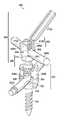
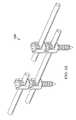
- FIG. 2depicts an elevational view of a modular head-to-head cross connecting system for percutaneous delivery, in accordance with one embodiment of the present disclosure
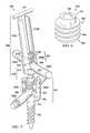
- FIG. 3depicts an elevational view of a first U-shaped body of the modular head-to-head cross connecting system of FIG. 2 , in accordance with one embodiment of the present disclosure
- FIG. 4depicts an elevational view of a second U-shaped body of the modular head-to-head cross connecting system of FIG. 2 , in accordance with one embodiment of the present disclosure
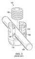
- FIG. 5depicts an elevational view of a modular compression element of the modular head-to-head cross connecting system of FIG. 2 , in accordance with one embodiment of the present disclosure
- FIG. 6depicts an elevational view of a non-modular compression element, in accordance with one embodiment of the present disclosure
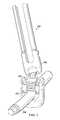
- FIG. 7depicts an elevational view of a modular head-to-head cross connecting system for percutaneous delivery with a second rod set in the second U-shaped body, in accordance with one embodiment of the present disclosure
- FIG. 8depicts an elevational view of FIG. 7 with a first arm removed from the second U-shaped body removed and a second arm of the second U-shaped body in the process of being removed, in accordance with one embodiment of the present disclosure
- FIG. 9depicts an elevational view of a modular head-to-head cross connecting system comprising four rods set in a square arrangement, in accordance with one embodiment of the present disclosure.
- FIG. 10depicts an elevational view of a modular construct extension system comprising two rods set in an in-line arrangement, in accordance with one embodiment of the present disclosure.
- interference fitin intended to refer to physical contact between two or more components and may include a slip fit, a ball-joint fit, or similar fit between two or more components.
- FIG. 1depicts a prior art connection system 100 for connecting a fastener element (e.g., a pedicle screw, not shown) relative to a rod 104 for vertebral fixation.
- Connection system 100may comprise a U-shaped body 102 , the rod 104 , and a compression element 106 .
- the rod 104may be shaped to fit within the U-shaped body 102 at a rod receiving channel 108 with a slip fit.
- the compression element 106may be threaded into the U-shaped body 102 and mate with internal threads 110 of the U-shaped body 102 .
- the compression element 106may clamp the rod 104 against an orbital head of the fastener element when the fastener element is received into an orbital recess 112 of the U-shaped body 102 .
- the U-shaped body 102may be operable to rotate about the orbital head of the fastener element received into the orbital recess 112 in order to allow multi-axial rotation of the rod 104 relative to the fastener element.
- the fastener element and the U-shaped body 102may comprise separate components or may comprise a single component wherein the fastener element is operable to rotate independently of the U-shaped body 102 .
- FIG. 2depicts an elevational view of a modular head-to-head cross connecting system 200 for percutaneous delivery, in accordance with one embodiment of the present disclosure.
- the modular head-to-head cross connecting system 200may comprise a first U-shaped body 202 , a rod 204 , a modular compression element 206 , and a second U-shaped body 208 .
- Each of the components of the modular head-to-head cross connecting system 200will be described in more detail in relation to corresponding FIGS. 3-10 .
- FIG. 3depicts an elevational view of the first U-shaped body 202 of the modular head-to-head cross connecting system of FIG. 2 , in accordance with one embodiment of the present disclosure.
- the first U-shaped body 202may comprise a body 302 comprising a rod receiving channel 304 , a first body side 308 A, and a second body side 308 B.
- the rod receiving channel 304may be located at a distal end 318 and may define the first and second body sides 308 A, 308 B.
- the first and second body sides 308 A, 308 Bmay comprise internal threads 306 located proximate to the rod receiving channel 304 and configured to receive the rod 204 and the modular compression element 206 , as shown in FIG. 2 and described in more detail in FIGS. 7-8 .
- the body 302may further comprise an internal orbital recess 314 proximate to a proximal end 316 and opposite the rod receiving channel 304 .
- the internal orbital recess 314may be operable to receive an orbital head of a fastener element (e.g., pedicle screw, not shown).
- the first U-shaped body 202may be operable to rotate about the orbital head of the fastener element (not shown) received into the orbital recess 314 in order to allow multi-axial rotation of the body 302 and a rod (not shown) relative to the fastener element.
- the first U-shaped body 202may further comprise first and second removable arms (not shown) operable to be removed from the body 302 at creases proximate to the intersection of the first and second removable arms and the body 302 .
- the first and second removable armsmay be located proximate to the distal end 318 .
- FIG. 4depicts an elevational view of the second U-shaped body 208 of the modular head-to-head cross connecting system of FIG. 2 , in accordance with one embodiment of the present disclosure.
- the second U-shaped body 208may comprise a body 402 comprising a rod receiving channel 404 , a first body side 408 A, and a second body side 408 B.
- the rod receiving channel 404may be located at a distal end 418 and may define the first and second body sides 408 A, 408 B.
- the first and second body sides 408 A, 408 Bmay comprise internal threads 406 located proximate to the rod receiving channel 304 and configured to receive the rod 204 and a non-modular compression element, as described in more detail in FIGS. 7-8 .
- the body 402may further comprise an internal orbital recess 404 proximate to a proximal end 416 and opposite the rod receiving channel 404 .
- the internal orbital recess 414may be operable to receive an orbital head of the modular compression element 206 , as shown in FIG. 2 .
- the second U-shaped body 208may be operable to rotate about the orbital head of the modular compression (not shown) element received into the orbital recess 414 in order to allow multi-axial rotation of the body 402 and a rod (not shown) relative to the modular compression element.
- the second U-shaped body 208may further comprise first and second removable arms 412 A, 412 B operable to be removed from the body 402 at creases 410 A, 410 B.
- the first and second removable arms 412 A, 412 Bmay be located proximate to the distal end 418 .
- FIG. 5depicts an elevational view of the modular compression element 206 of the modular head-to-head cross connecting system of FIG. 2 , in accordance with one embodiment of the present disclosure.
- the modular compression element 206may comprise an orbital head 502 located at a distal end 512 connected to a compression element body 506 at a proximal end 510 .
- Part or all of the compression element body 506may comprise threads 508 about the compression element body 506 .
- the threads 508may allow the modular compression element 206 to mate with the threads of the first and second body sides of the first U-shaped body shown in FIG. 3 .
- the orbital head 502 of the modular compression element 206may further comprise a driving recess 504 operable to receive a driving instrument (not shown). Although shown as a square-shaped driving recesses 504 in FIG. 5 , the driving recess 504 may be hex-shaped, Philips-head shaped, flathead-shaped, or any other shape operable to receive a driving instrument.
- FIG. 6depicts an elevational view of a non-modular compression element 600 , in accordance with one embodiment of the present disclosure.
- the non-modular compression element 600may comprise a compression element body 602 comprising a proximal end 608 and a distal end 610 .
- Part or all of the compression element body 602may comprise threads 604 about the compression element body 602 .
- the threads 604may allow the non-modular compression element 600 to mate with the threads of the first and second body sides of the second U-shaped body shown in FIG. 4 .
- the distal end 610 of the non-modular compression element 600may further comprise a driving recess 606 operable to receive a driving instrument (not shown). Although shown as a square-shaped driving recesses 606 in FIG. 6 , the driving recess 606 may be a hex-shaped, Philips-head shaped, flathead-shaped, or any other shape operable to receive a driving instrument.
- FIG. 7depicts an elevational view of the modular head-to-head cross connecting system 200 for percutaneous delivery with a first rod 204 A received in the first U-shaped body 202 and a second rod 204 B received in the second U-shaped body 208 , in accordance with one embodiment of the present disclosure.
- FIG. 8depicts an elevational view of FIG. 7 with the first removable arm 412 A removed from the second U-shaped body 208 and the second removable arm 412 A of the second U-shaped body 208 detached from the second U-shaped body 208 , in accordance with one embodiment of the present disclosure.
- a fastener element 700may comprise an orbital head 702 and may be a threaded pedicle bone screw.
- the fastener element 700may be driven into a bone such as a pedicle in a first orientation with a driving element (not shown) during a surgical procedure.
- the first U-shaped body 202may be placed or “snapped” over the orbital head 702 so that the orbital recess 314 of the first U-shaped body 202 has an interference fit with the orbital head 702 of the fastener element 700 .
- the interference fit between the fastener element 700 and the first U-shaped body 202may be a ball-joint fit.
- the fastener element 700may be received through the distal end of the first U-shaped body 202 before the fastener element 700 is driven into the bone so that the first U-shaped body 202 receives the orbital head 702 of the fastener element 700 in the orbital recess 314 in the proximal end of the first U-shaped body 202 .
- the fastener element 700may then be driven into the bone in the first orientation with a driving element (not shown) during a surgical procedure.
- the first rod 204 Amay be received into the rod receiving channel 304 of the first U-shaped body 202 .
- the first rod 204 Amay be operable to slide along its axis within the rod receiving channel 304 and independent of the first U-shaped body 202 , and both the first U-shaped body 202 and the first rod 204 A may be operable to pivot in unison relative to the orbital head 702 of the fastener element 700 .
- the interference fitallows the first U-shaped body 202 to be rotated about the orbital head 702 of the fastener element 700 so that the first rod 204 A may be aligned in a second orientation independent of the first orientation of the fastener element 700 .
- the first U-shaped body 202may be circumferentially pivotable on the orbital head 702 of the fastener element 700 around a longitudinal axis defined by the first orientation of the fastener element 700 and/or may have a desired degree of angular freedom (e.g., approximately 26° from the longitudinal axis of the fastener element 700 or 52° from one side to the other).
- the modular compression element 206may be operable to be inserted into the rod receiving channel 304 of the first U-shaped body 202 .
- the modular compression element 206may be operable to be driven down onto the first rod 204 A with a driving element (not shown).
- the threads 508 of the modular compression element 206may be operable mate with the internal threads 306 of the first and second body sides 308 A, 308 B of the first U-shaped body 202 , allowing the first rod 204 A to be operable to be driven against an end of the rod receiving channel 304 .
- the distal end of the modular compression element 206may be in an interference fit with a first surface of the first rod 204 A and a second surface of the first rod 204 A may be in an interference fit with a surface of the orbital head 702 of the fastener element 700 .
- the snug interference fit between the modular compression element 206 and the first rod 204 A and between the first rod 204 A and the orbital head 702may be a slip fit that allows minor displacement of the first rod 204 A slidably along its axis relative to the first U-shaped body 202 and allow the first rod 204 A and the first U-shaped body 202 minor pivotable adjustment relative to the fastener 700 when setting the second orientation of the first rod 204 A.
- the modular compression element 206may be further driven against the first rod 204 A so that the second orientation of the first rod 204 A relative to the first orientation of the fastener element 700 is set and minor adjustments to the second are no longer possible.
- the first U-shaped body 202may optionally comprise first and second removable arms (corresponding to the first and second removable arms 512 A, 512 B of the second U-shaped body 208 in FIG. 4 ). After the second orientation of the first rod 204 A has been set, the first and second removable arms may be detached from the first U-shaped body 202 at first and second creases.
- the second U-shaped body 208may be placed or “snapped” over the orbital head 502 of the modular compression element 206 so that the orbital recess 414 of the second U-shaped body 208 has an interference fit with the orbital head 502 of modular compression element 206 .
- the second rod 204 Bmay be received into the rod receiving channel 404 of the second U-shaped body 208 .
- the orbital head 502 of the modular compression element 206may be received in the orbital recess 414 of the second U-shaped body 208 before the modular compression element 206 is driven into the first U-shaped body 202 and against the first rod 204 A.
- the modular compression element 206may then be driven adjacent to and against the first rod 204 A with a driving element (not shown) during a surgical procedure.
- the interference fit between the modular compression element 206 and the second U-shaped body 208may be a ball-joint fit that allows the second U-shaped body 208 and the second rod 204 B to pivot about the orbital head 502 of the modular compression element 206 so that the second rod 204 B may be aligned in a third orientation independent of the second orientation of the first rod 204 A and independent of the first orientation of the fastener element 700 .
- the second U-shaped body 208may be circumferentially pivotable on the orbital head 502 of the modular compression element 206 around a longitudinal axis defined from the proximal end to the distal end of the modular compression element 206 and/or may have a desired degree of angular freedom (e.g., approximately 26° from the longitudinal axis of the modular compression element 206 or 52° from one side to the other).
- the second rod 204 Bmay be operable to slide along its axis within the rod receiving channel 404 independent of the second U-shaped body 208 , and both the second U-shaped body 208 and the second rod 204 B may be operable to pivot in unison relative to the modular compression element 206 in order to set the third orientation of the second rod 204 B.
- the non-modular compression element 600may be operable to be inserted into the rod receiving channel 404 of the second U-shaped body 208 .
- the non-modular compression element 600may be operable to be driven down onto the second rod 204 B with a driving element 704 .
- the driving element 704may also be operable to drive the fastener element 700 and the modular compression element 206 .
- the threads 604 of the non-modular compression element 600may be operable mate with the internal threads 406 of the first and second body sides 408 A, 408 B of the second U-shaped body 208 , allowing the second rod 204 B to be operable to be driven against an end of the rod receiving channel 404 .
- the distal end of the non-modular compression element 600may be in an interference fit with a first surface of the second rod 204 B and a second surface of the second rod 204 B may be in an interference fit with a surface of the orbital head 502 of the modular compression element 206 .
- the snug interference fit between the non-modular compression element 600 and the second rod 204 B and between the second rod 204 B and the orbital head 502may be a slip fit that allows minor displacement of the second rod 204 B along its axis relative to the second U-shaped body 208 and may allow the second rod 204 B and the second U-shaped body 208 minor pivotable adjustment relative to the modular compression element 206 when setting the third orientation of the second rod 204 B.
- the non-modular compression element 600may be further driven against the second rod 204 B so that the third orientation of the second rod 204 B is set, and minor adjustments of third orientation of the second rod 204 B are no longer possible.
- each of the first, second, and third orientationsmay be set independently of each other.
- the first and second removable arms 412 A, 412 Bmay be detached from the second U-shaped body 208 at the first and second creases 410 A, 410 B.
- the first removable arm 412 Ahas been removed from the second U-shaped body 208 and the second removable arm 412 B is in the process of being removed from the second U-shaped body 208 and has been bent approximately 45° at the second crease 410 B relative to the body 402 of the second U-shaped body 208 .
- FIGS. 7 and 8depict only one U-shaped body affixed to each rod, it is to be understood that any number of U-shaped bodies can be affixed to each rod and that more than two U-shaped bodies may be stacked on top of each other in order to allow for more than two levels of rods to be used.
- FIG. 9depicts an elevational view of a modular head-to-head cross connecting system 900 comprising four rods set in a rectangular arrangement, in accordance with one embodiment of the present disclosure.
- the first orientations of the fastener elements in the pedicle bodiesmay be independent of the second orientations of the rods proximate to the fastener elements, which may be independent of the third orientations of the rods distant to the fastener elements.
- FIG. 10depicts an elevational view of a modular construct extension system 1000 comprising three rods set in an in-line arrangement, in accordance with one embodiment of the present disclosure.
- one or more extension rodsmay be used to extend a first rod, for example to adjacent spinal segments or the pelvis.
- Each extension rodmay be affixed proximally or distally to a first construct comprising a combination of rods, U-shaped bodies, modular compression elements, and non-modular compression elements.
- each extension rodmay be affixed to a second construct comprising a combination of rods, U-shaped bodies, modular compression elements, and non-modular compression elements, wherein the first construct and the second construct are located at opposite ends of the extension rod.
- the one ore more extension rodsmay be implanted at the same time as the first rod or at a later time via either traditional, “open” surgical techniques or via minimally invasive surgical techniques.
- one or more rodsmay be approximately 5.5 mm diameter rods, while in another embodiment one or more rods may be approximately 3.0-3.5 mm diameter rods.
- the length of the rodsmay be determined by the desired application of the modular head-to-head cross connector system.
- the disclosed embodimentsallow for percutaneous delivery of the modular head-to-head cross connector system.
- One or more components of the modular head-to-head cross connecting systems disclosed hereinmay be made from any of the following materials: (a) any biocompatible material (which biocompatible material may be treated to permit bone ingrowth or prohibit bone ingrowth); (b) a plastic; (c) a fiber; (d) a polymer; (e) a metal (e.g., a pure metal such as titanium and/or an alloy such as Ti—Al—Nb, TI-6A1-4V, stainless steel); or (f) any combination thereof.
Landscapes
- Health & Medical Sciences (AREA)
- Orthopedic Medicine & Surgery (AREA)
- Life Sciences & Earth Sciences (AREA)
- Surgery (AREA)
- Neurology (AREA)
- Heart & Thoracic Surgery (AREA)
- Engineering & Computer Science (AREA)
- Biomedical Technology (AREA)
- Nuclear Medicine, Radiotherapy & Molecular Imaging (AREA)
- Medical Informatics (AREA)
- Molecular Biology (AREA)
- Animal Behavior & Ethology (AREA)
- General Health & Medical Sciences (AREA)
- Public Health (AREA)
- Veterinary Medicine (AREA)
- Surgical Instruments (AREA)
- Prostheses (AREA)
Abstract
Description
Claims (30)
Priority Applications (1)
| Application Number | Priority Date | Filing Date | Title |
|---|---|---|---|
| US14/703,527US9439684B2 (en) | 2012-11-09 | 2015-05-04 | Percutaneous modular head-to-head cross connector |
Applications Claiming Priority (2)
| Application Number | Priority Date | Filing Date | Title |
|---|---|---|---|
| US13/672,928US9023087B2 (en) | 2012-11-09 | 2012-11-09 | Percutaneous modular head-to-head cross connector |
| US14/703,527US9439684B2 (en) | 2012-11-09 | 2015-05-04 | Percutaneous modular head-to-head cross connector |
Related Parent Applications (1)
| Application Number | Title | Priority Date | Filing Date |
|---|---|---|---|
| US13/672,928ContinuationUS9023087B2 (en) | 2012-11-09 | 2012-11-09 | Percutaneous modular head-to-head cross connector |
Publications (2)
| Publication Number | Publication Date |
|---|---|
| US20150230830A1 US20150230830A1 (en) | 2015-08-20 |
| US9439684B2true US9439684B2 (en) | 2016-09-13 |
Family
ID=50682424
Family Applications (2)
| Application Number | Title | Priority Date | Filing Date |
|---|---|---|---|
| US13/672,928Expired - Fee RelatedUS9023087B2 (en) | 2012-11-09 | 2012-11-09 | Percutaneous modular head-to-head cross connector |
| US14/703,527Expired - Fee RelatedUS9439684B2 (en) | 2012-11-09 | 2015-05-04 | Percutaneous modular head-to-head cross connector |
Family Applications Before (1)
| Application Number | Title | Priority Date | Filing Date |
|---|---|---|---|
| US13/672,928Expired - Fee RelatedUS9023087B2 (en) | 2012-11-09 | 2012-11-09 | Percutaneous modular head-to-head cross connector |
Country Status (7)
| Country | Link |
|---|---|
| US (2) | US9023087B2 (en) |
| EP (1) | EP2916753A4 (en) |
| JP (1) | JP6320402B2 (en) |
| AU (1) | AU2013342149A1 (en) |
| BR (1) | BR112015010631A2 (en) |
| CA (1) | CA2891776A1 (en) |
| WO (1) | WO2014074892A1 (en) |
Cited By (1)
| Publication number | Priority date | Publication date | Assignee | Title |
|---|---|---|---|---|
| US10413331B2 (en) | 2016-12-21 | 2019-09-17 | Spine Wave, Inc. | Spinal stabilization system with head to head cross connector |
Families Citing this family (41)
| Publication number | Priority date | Publication date | Assignee | Title |
|---|---|---|---|---|
| US9247964B1 (en) | 2011-03-01 | 2016-02-02 | Nuasive, Inc. | Spinal Cross-connector |
| US9387013B1 (en) | 2011-03-01 | 2016-07-12 | Nuvasive, Inc. | Posterior cervical fixation system |
| US8852241B2 (en)* | 2011-08-04 | 2014-10-07 | Devin Datta | Surgical devices and methods providing sacroiliac stabilization |
| US8740950B2 (en)* | 2011-12-08 | 2014-06-03 | Spine Wave, Inc. | Methods for percutaneously attaching a cross connector to contralateral spinal constructs |
| US10327818B2 (en) | 2012-06-18 | 2019-06-25 | Bruce Francis Hodgson | Method and apparatus for the treatment of scoliosis |
| CA2903160A1 (en)* | 2012-06-18 | 2014-12-27 | Bruce Francis HODGSON | Method and apparatus for the treatment of scoliosis |
| US9675386B2 (en) | 2013-03-11 | 2017-06-13 | K2M, Inc. | Flexible fastening system |
| US20140277163A1 (en)* | 2013-03-15 | 2014-09-18 | Ryan Kretzer | Reinforcement systems for spine stabilization constructs |
| GB2512063B (en)* | 2013-03-18 | 2019-05-29 | Fitzbionics Ltd | Spinal implant assembly |
| WO2015023420A2 (en)* | 2013-07-25 | 2015-02-19 | Latitude Holdings, Llc | Percutaneous pedicle screw revision system |
| US20150094769A1 (en) | 2013-10-01 | 2015-04-02 | Hamid Abbasi | System and method for lengthening an existing spinal support structure |
| JP2016539762A (en)* | 2013-10-31 | 2016-12-22 | ザ ユニバーシティ オブ アイオワ リサーチ ファウンデーションThe University of Iowa Research Foundation | Transcutaneous lateral connector system |
| US9402666B2 (en) | 2014-04-30 | 2016-08-02 | King Faisal Specialist Hospital & Research Centre | Vertebral fixation device |
| US11547450B2 (en)* | 2015-04-17 | 2023-01-10 | Apifix Ltd. | Expandable polyaxial spinal system |
| US10383663B2 (en)* | 2016-03-29 | 2019-08-20 | Globus Medical, Inc. | Revision connectors, systems and methods thereof |
| US10517647B2 (en) | 2016-05-18 | 2019-12-31 | Medos International Sarl | Implant connectors and related methods |
| US10321939B2 (en) | 2016-05-18 | 2019-06-18 | Medos International Sarl | Implant connectors and related methods |
| US10413330B2 (en)* | 2016-08-09 | 2019-09-17 | Warsaw Orthopedic, Inc. | Spinal implant system and method |
| EP3525699B1 (en) | 2016-10-11 | 2023-07-26 | K2M, Inc. | Spinal implant |
| US10398476B2 (en) | 2016-12-13 | 2019-09-03 | Medos International Sàrl | Implant adapters and related methods |
| US10492835B2 (en) | 2016-12-19 | 2019-12-03 | Medos International Sàrl | Offset rods, offset rod connectors, and related methods |
| US10238432B2 (en)* | 2017-02-10 | 2019-03-26 | Medos International Sàrl | Tandem rod connectors and related methods |
| US10736665B2 (en) | 2017-02-24 | 2020-08-11 | Warsaw Orthopedic, Inc. | Spinal implant system and method |
| US10172653B2 (en)* | 2017-03-09 | 2019-01-08 | Alphatec Spine, Inc. | Osteotomy instrument |
| US10561454B2 (en) | 2017-03-28 | 2020-02-18 | Medos International Sarl | Articulating implant connectors and related methods |
| US10966761B2 (en) | 2017-03-28 | 2021-04-06 | Medos International Sarl | Articulating implant connectors and related methods |
| US12144523B2 (en)* | 2017-04-10 | 2024-11-19 | Life Spine, Inc. | Head over head connector assembly |
| US12127765B2 (en) | 2017-04-10 | 2024-10-29 | Life Spine, Inc. | Bottom loading polyaxial screw |
| US11648037B2 (en) | 2017-05-03 | 2023-05-16 | Advance Research System, Llc | Extension-ready spinal support system with vascular-safe pedicle screw |
| WO2018204676A1 (en)* | 2017-05-03 | 2018-11-08 | Advance Research System, Llc | Extension ready spinal support systems |
| US10456174B2 (en)* | 2017-07-31 | 2019-10-29 | Medos International Sarl | Connectors for use in systems and methods for reducing the risk of proximal junctional kyphosis |
| US10463403B2 (en) | 2017-07-31 | 2019-11-05 | Medos International Sarl | Systems and methods for reducing the risk of proximal junctional kyphosis using a bone anchor or other attachment point |
| US11076890B2 (en) | 2017-12-01 | 2021-08-03 | Medos International Sàrl | Rod-to-rod connectors having robust rod closure mechanisms and related methods |
| WO2020035958A1 (en)* | 2018-08-16 | 2020-02-20 | Medtronic Sofamor Danek, Co., Ltd. | Spinal implant system and method |
| AU2019398345B2 (en)* | 2018-12-12 | 2025-09-11 | Orthopediatrics Corp. | Bone anchor head extender |
| US11571244B2 (en)* | 2019-05-22 | 2023-02-07 | Nuvasive, Inc. | Posterior spinal fixation screws |
| US11660126B1 (en)* | 2019-06-28 | 2023-05-30 | Advance Research System, Llc | Iliac anchor system |
| US11311317B2 (en)* | 2019-09-25 | 2022-04-26 | Stelios KOUTSOUMBELIS | Spinal fixation device with rotatable connector |
| US20220110661A1 (en)* | 2020-10-12 | 2022-04-14 | Globus Medical, Inc. | Scoliosis correction systems, methods, and instruments |
| US20240041502A1 (en)* | 2020-12-14 | 2024-02-08 | Johannes Hendrik Davis | Spinal rod coupler and system for spinal corrective surgery |
| US11998244B2 (en) | 2021-04-09 | 2024-06-04 | Snj Patents, Llc | Minimally invasive surgery add on screw system |
Citations (78)
| Publication number | Priority date | Publication date | Assignee | Title |
|---|---|---|---|---|
| US5885286A (en)* | 1996-09-24 | 1999-03-23 | Sdgi Holdings, Inc. | Multi-axial bone screw assembly |
| US6224598B1 (en)* | 2000-02-16 | 2001-05-01 | Roger P. Jackson | Bone screw threaded plug closure with central set screw |
| US6485491B1 (en)* | 2000-09-15 | 2002-11-26 | Sdgi Holdings, Inc. | Posterior fixation system |
| US20030199873A1 (en)* | 2002-04-18 | 2003-10-23 | Marc Richelsoph | Screw and rod fixation assembly and device |
| US6676661B1 (en)* | 1999-07-23 | 2004-01-13 | Antonio Martin Benlloch | Multiaxial connector for spinal implant |
| US20040116928A1 (en)* | 2002-10-28 | 2004-06-17 | Young J. Stewart | Multi-axial, cross-link connector system for spinal implants |
| US20050240265A1 (en)* | 2004-04-22 | 2005-10-27 | Kuiper Mark K | Crossbar spinal prosthesis having a modular design and related implantation methods |
| US20060064091A1 (en)* | 2004-03-31 | 2006-03-23 | Depuy Spine, Inc. | Rod attachment for head to head cross connector |
| US7163538B2 (en)* | 2002-02-13 | 2007-01-16 | Cross Medical Products, Inc. | Posterior rod system |
| US20070073291A1 (en)* | 2005-09-12 | 2007-03-29 | Seaspine, Inc. | Implant system for Osteosynthesis |
| US7204838B2 (en)* | 2004-12-20 | 2007-04-17 | Jackson Roger P | Medical implant fastener with nested set screw and method |
| US20070233078A1 (en)* | 2006-01-27 | 2007-10-04 | Justis Jeff R | Pivoting joints for spinal implants including designed resistance to motion and methods of use |
| US20070250061A1 (en)* | 2006-04-24 | 2007-10-25 | Spinefrontier Lls | Spine fixation method and apparatus |
| US20070270832A1 (en)* | 2006-05-01 | 2007-11-22 | Sdgi Holdings, Inc. | Locking device and method, for use in a bone stabilization system, employing a set screw member and deformable saddle member |
| US20070276374A1 (en)* | 2005-03-02 | 2007-11-29 | Richard Broman | Arthroplasty revision system and method |
| US20080071274A1 (en)* | 2006-09-15 | 2008-03-20 | Ensign Michael D | Percutaneous Screw Assembly and Placement Method |
| US20080097441A1 (en)* | 2004-10-20 | 2008-04-24 | Stanley Kyle Hayes | Systems and methods for posterior dynamic stabilization of the spine |
| US20080119858A1 (en)* | 2006-11-16 | 2008-05-22 | Spine Wave, Inc. | Multi-Axial Spinal Fixation System |
| US20080177318A1 (en)* | 2007-01-18 | 2008-07-24 | Warsaw Orthopedic, Inc. | Vertebral Stabilizer |
| US20080221622A1 (en)* | 2007-01-10 | 2008-09-11 | Facet Solutions, Inc. | Facet Joint Replacement |
| US20080306527A1 (en)* | 2007-06-05 | 2008-12-11 | Spartek Medical, Inc. | Dynamic stabilization and motion preservation spinal implantation system with a shielded deflection rod system and method |
| US20080306513A1 (en)* | 2007-06-05 | 2008-12-11 | Spartek Medical, Inc. | Shaped horizontal rod for dynamic stabilization and motion preservation spinal implantation system and method |
| US20080312692A1 (en)* | 2007-06-15 | 2008-12-18 | Terrence Brennan | Multi-level spinal stabilization system |
| US20090024169A1 (en)* | 2004-06-02 | 2009-01-22 | Facet Solutions, Inc. | System and method for multiple level facet joint arthroplasty and fusion |
| US20090030463A1 (en)* | 2007-07-09 | 2009-01-29 | Alphatec Spine, Inc. | Occipital fixation screw |
| US20090036934A1 (en)* | 2007-07-31 | 2009-02-05 | Lutz Biedermann | Bone anchoring device |
| US20090069852A1 (en)* | 2007-09-06 | 2009-03-12 | Warsaw Orthopedic, Inc. | Multi-Axial Bone Anchor Assembly |
| US20090105760A1 (en)* | 2007-07-13 | 2009-04-23 | George Frey | Systems and methods for spinal stabilization |
| US20090118772A1 (en)* | 2007-06-01 | 2009-05-07 | Jennifer Diederich | Polyaxial bone anchor with increased angulation |
| US20090216277A1 (en)* | 2008-02-26 | 2009-08-27 | Clariance | Posterior lumbar joint prosthesis |
| US20090254125A1 (en)* | 2008-04-03 | 2009-10-08 | Daniel Predick | Top Loading Polyaxial Spine Screw Assembly With One Step Lockup |
| US20090264926A1 (en)* | 2008-04-19 | 2009-10-22 | Warsaw Orthopedic, Inc. | Spinal Fixation System |
| US20090299411A1 (en)* | 2008-05-30 | 2009-12-03 | Daniel Laskowitz | System and Method for Replacement of Spinal Motion Segment |
| US7645294B2 (en)* | 2004-03-31 | 2010-01-12 | Depuy Spine, Inc. | Head-to-head connector spinal fixation system |
| US20100030270A1 (en)* | 2007-06-05 | 2010-02-04 | Spartek Medical, Inc. | Dynamic spinal rod assembly and method for dynamic stabilization of the spine |
| US20100036432A1 (en)* | 2008-08-05 | 2010-02-11 | Abbott Spine Inc. | Twist off reduction screw |
| US20100036417A1 (en)* | 2008-08-06 | 2010-02-11 | Spine Wave, Inc. | Multi-axial spinal fixation system |
| US20100036436A1 (en)* | 2008-02-26 | 2010-02-11 | Spartek Medical, Inc. | Load-sharing bone anchor having a durable compliant member and method for dynamic stabilization of the spine |
| US20100042152A1 (en)* | 2008-08-12 | 2010-02-18 | Blackstone Medical Inc. | Apparatus for Stabilizing Vertebral Bodies |
| US20100057131A1 (en)* | 2008-08-29 | 2010-03-04 | Abbott Spine Inc. | Polyaxial transverse connector |
| US20100057136A1 (en)* | 2008-09-02 | 2010-03-04 | Heiges Bradley A | Modular pedicle screw system with tap and screw driver device |
| US20100057135A1 (en)* | 2008-09-02 | 2010-03-04 | Heiges Bradley A | Modular pedicle screw system |
| US7691145B2 (en)* | 1999-10-22 | 2010-04-06 | Facet Solutions, Inc. | Prostheses, systems and methods for replacement of natural facet joints with artificial facet joint surfaces |
| US20100094345A1 (en)* | 2006-09-26 | 2010-04-15 | Sean Saidha | Transconnector |
| US20100160981A1 (en)* | 2008-12-22 | 2010-06-24 | Butler Michael S | Posterior Cervical Cross Connector Assemblies |
| US20100222822A1 (en)* | 2002-08-28 | 2010-09-02 | Warsaw Orthopedic, Inc. | Posterior Fixation System |
| US20100280552A1 (en)* | 2009-05-04 | 2010-11-04 | Choon Sung Lee | Side click connector apparatus for connection of spinal rods |
| US7833251B1 (en)* | 2004-01-06 | 2010-11-16 | Nuvasive, Inc. | System and method for performing spinal fixation |
| US20100298884A1 (en)* | 2009-05-21 | 2010-11-25 | Custom Spine, Inc. | Polyaxial Auxiliary Connector |
| US7896902B2 (en)* | 2006-04-05 | 2011-03-01 | Dong Myung Jeon | Multi-axial double locking bone screw assembly |
| US20110106178A1 (en)* | 2009-10-29 | 2011-05-05 | Warsaw Orthopedic, Inc. | Pedicle screw head extender |
| US20110137345A1 (en)* | 2009-03-18 | 2011-06-09 | Caleb Stoll | Posterior lumbar fusion |
| USRE42545E1 (en)* | 1995-04-13 | 2011-07-12 | Warsaw Orthopedic, Inc. | Polyaxial pedicle screw having a threaded and tapered compression locking mechanism |
| US20110178558A1 (en)* | 2010-01-15 | 2011-07-21 | Ebi, Llc | Uniplanar bone anchor system |
| US20110213419A1 (en)* | 2007-10-23 | 2011-09-01 | Blackstone Medical Inc. | Spinal Implant |
| US8012184B2 (en)* | 2002-12-06 | 2011-09-06 | Synthes Usa, Llc | Device for stabilizing bones |
| US20110218579A1 (en)* | 2003-06-18 | 2011-09-08 | Jackson Roger P | Polyaxial bone anchor with helical capture connection, insert and dual locking assembly |
| US8100909B2 (en)* | 2008-03-27 | 2012-01-24 | Life Spine, Inc. | Self-contained assembly for installation of orthopedic implant components onto an orthopedic implant |
| US20120095511A1 (en)* | 2010-10-18 | 2012-04-19 | Raj Nihalani | Cross connectors |
| US20120095510A1 (en)* | 2010-10-18 | 2012-04-19 | Raj Nihalani | Cross connectors |
| US20120123478A1 (en)* | 2009-12-02 | 2012-05-17 | Spartek Medical, Inc. | Low profile spinal prosthesis incorporating a bone anchor having a deflectable post and a compound spinal rod |
| US8197512B1 (en)* | 2008-07-16 | 2012-06-12 | Zimmer Spine, Inc. | System and method for spine stabilization using resilient inserts |
| US20120150230A1 (en)* | 2010-12-09 | 2012-06-14 | Innovasis, Inc. | Cross connector with central hub |
| US20120226316A1 (en)* | 2011-03-04 | 2012-09-06 | Zimmer Spine, Inc. | Transverse connector |
| US20120253400A1 (en)* | 2011-03-31 | 2012-10-04 | Corporation Spinelab AG | Vertebral column implant |
| US20120253401A1 (en)* | 2011-03-31 | 2012-10-04 | Spinelab Ag | Vertebral column implant for stabilization and stiffening of vertebral bodies of a vertebral column |
| US20120253402A1 (en)* | 2010-06-18 | 2012-10-04 | Spine Wave, Inc. | Pedicle screw extension for use in percutaneous spinal fixation |
| US20120277806A1 (en)* | 2011-04-27 | 2012-11-01 | Jeffrey Scott Smith | Tulip Head Apparatus |
| US20120283778A1 (en)* | 2010-03-31 | 2012-11-08 | Chung-Chun Yeh | Device for connecting transverse beam at triangular position of vertebral lamina |
| US20130103092A1 (en)* | 2011-10-25 | 2013-04-25 | Warsaw Orthopedic, Inc. | Pre-assembled spinal construct and method of use |
| US20130172934A1 (en)* | 2011-12-30 | 2013-07-04 | Blackstone Medical, Inc. | Multi-axial spinal cross connecting device |
| US20130184759A1 (en) | 2011-12-14 | 2013-07-18 | Spinicity, Inc. | Minimally Invasive Method And Apparatus For Stabilizing The Spinal Column |
| US20130325069A1 (en)* | 2010-11-29 | 2013-12-05 | Javier Pereiro de Lamo | Method and System for the Treatment of Spinal Deformities |
| US20140012333A1 (en)* | 2012-07-06 | 2014-01-09 | Clariance | Polyaxial screw with mechanical thread and its friction device |
| US20140018866A1 (en)* | 2012-01-01 | 2014-01-16 | Vaskrsije Jankovic | Surgical screw assembly with increased articulation |
| US8758411B1 (en)* | 2011-10-25 | 2014-06-24 | Nuvasive, Inc. | Implants and methods for treating spinal disorders |
| US20140180338A1 (en)* | 2007-01-10 | 2014-06-26 | Globus Medical, Inc | System and Method for Bone Anchorage |
| US8852241B2 (en)* | 2011-08-04 | 2014-10-07 | Devin Datta | Surgical devices and methods providing sacroiliac stabilization |
Family Cites Families (2)
| Publication number | Priority date | Publication date | Assignee | Title |
|---|---|---|---|---|
| JP4976371B2 (en)* | 2005-03-25 | 2012-07-18 | ブラックストーン メディカル,インコーポレイティド | Multi-axis connection system |
| ES2378588T3 (en)* | 2008-12-30 | 2012-04-16 | Biedermann Motech Gmbh | Receiving part for receiving a rod for coupling the rod in a bone anchoring element and bone anchoring device with such receiving part |
- 2012
- 2012-11-09USUS13/672,928patent/US9023087B2/ennot_activeExpired - Fee Related
- 2013
- 2013-11-08EPEP13853123.1Apatent/EP2916753A4/ennot_activeWithdrawn
- 2013-11-08JPJP2015541947Apatent/JP6320402B2/enactiveActive
- 2013-11-08AUAU2013342149Apatent/AU2013342149A1/ennot_activeAbandoned
- 2013-11-08WOPCT/US2013/069262patent/WO2014074892A1/enactiveApplication Filing
- 2013-11-08CACA2891776Apatent/CA2891776A1/ennot_activeAbandoned
- 2013-11-08BRBR112015010631Apatent/BR112015010631A2/ennot_activeApplication Discontinuation
- 2015
- 2015-05-04USUS14/703,527patent/US9439684B2/ennot_activeExpired - Fee Related
Patent Citations (81)
| Publication number | Priority date | Publication date | Assignee | Title |
|---|---|---|---|---|
| USRE42545E1 (en)* | 1995-04-13 | 2011-07-12 | Warsaw Orthopedic, Inc. | Polyaxial pedicle screw having a threaded and tapered compression locking mechanism |
| US5885286A (en)* | 1996-09-24 | 1999-03-23 | Sdgi Holdings, Inc. | Multi-axial bone screw assembly |
| US6676661B1 (en)* | 1999-07-23 | 2004-01-13 | Antonio Martin Benlloch | Multiaxial connector for spinal implant |
| US7691145B2 (en)* | 1999-10-22 | 2010-04-06 | Facet Solutions, Inc. | Prostheses, systems and methods for replacement of natural facet joints with artificial facet joint surfaces |
| US6224598B1 (en)* | 2000-02-16 | 2001-05-01 | Roger P. Jackson | Bone screw threaded plug closure with central set screw |
| US6485491B1 (en)* | 2000-09-15 | 2002-11-26 | Sdgi Holdings, Inc. | Posterior fixation system |
| US20030004512A1 (en) | 2000-09-15 | 2003-01-02 | Farris Robert A. | Posterior fixation system |
| US7163538B2 (en)* | 2002-02-13 | 2007-01-16 | Cross Medical Products, Inc. | Posterior rod system |
| US20030199873A1 (en)* | 2002-04-18 | 2003-10-23 | Marc Richelsoph | Screw and rod fixation assembly and device |
| US20100222822A1 (en)* | 2002-08-28 | 2010-09-02 | Warsaw Orthopedic, Inc. | Posterior Fixation System |
| US20040116928A1 (en)* | 2002-10-28 | 2004-06-17 | Young J. Stewart | Multi-axial, cross-link connector system for spinal implants |
| US8012184B2 (en)* | 2002-12-06 | 2011-09-06 | Synthes Usa, Llc | Device for stabilizing bones |
| US20110218579A1 (en)* | 2003-06-18 | 2011-09-08 | Jackson Roger P | Polyaxial bone anchor with helical capture connection, insert and dual locking assembly |
| US7833251B1 (en)* | 2004-01-06 | 2010-11-16 | Nuvasive, Inc. | System and method for performing spinal fixation |
| US7645294B2 (en)* | 2004-03-31 | 2010-01-12 | Depuy Spine, Inc. | Head-to-head connector spinal fixation system |
| US7717939B2 (en) | 2004-03-31 | 2010-05-18 | Depuy Spine, Inc. | Rod attachment for head to head cross connector |
| US20060064091A1 (en)* | 2004-03-31 | 2006-03-23 | Depuy Spine, Inc. | Rod attachment for head to head cross connector |
| US20050240265A1 (en)* | 2004-04-22 | 2005-10-27 | Kuiper Mark K | Crossbar spinal prosthesis having a modular design and related implantation methods |
| US20090024169A1 (en)* | 2004-06-02 | 2009-01-22 | Facet Solutions, Inc. | System and method for multiple level facet joint arthroplasty and fusion |
| US20080097441A1 (en)* | 2004-10-20 | 2008-04-24 | Stanley Kyle Hayes | Systems and methods for posterior dynamic stabilization of the spine |
| US7204838B2 (en)* | 2004-12-20 | 2007-04-17 | Jackson Roger P | Medical implant fastener with nested set screw and method |
| US20070276374A1 (en)* | 2005-03-02 | 2007-11-29 | Richard Broman | Arthroplasty revision system and method |
| US20070073291A1 (en)* | 2005-09-12 | 2007-03-29 | Seaspine, Inc. | Implant system for Osteosynthesis |
| US20070233078A1 (en)* | 2006-01-27 | 2007-10-04 | Justis Jeff R | Pivoting joints for spinal implants including designed resistance to motion and methods of use |
| US7896902B2 (en)* | 2006-04-05 | 2011-03-01 | Dong Myung Jeon | Multi-axial double locking bone screw assembly |
| US20070250061A1 (en)* | 2006-04-24 | 2007-10-25 | Spinefrontier Lls | Spine fixation method and apparatus |
| US20070270832A1 (en)* | 2006-05-01 | 2007-11-22 | Sdgi Holdings, Inc. | Locking device and method, for use in a bone stabilization system, employing a set screw member and deformable saddle member |
| US20080071274A1 (en)* | 2006-09-15 | 2008-03-20 | Ensign Michael D | Percutaneous Screw Assembly and Placement Method |
| US20100094345A1 (en)* | 2006-09-26 | 2010-04-15 | Sean Saidha | Transconnector |
| US20080119858A1 (en)* | 2006-11-16 | 2008-05-22 | Spine Wave, Inc. | Multi-Axial Spinal Fixation System |
| US20130023932A1 (en) | 2007-01-10 | 2013-01-24 | Helgerson Joel R | System and Method for Facet Hoint Replacement |
| US20140180338A1 (en)* | 2007-01-10 | 2014-06-26 | Globus Medical, Inc | System and Method for Bone Anchorage |
| US20080221622A1 (en)* | 2007-01-10 | 2008-09-11 | Facet Solutions, Inc. | Facet Joint Replacement |
| US20080177318A1 (en)* | 2007-01-18 | 2008-07-24 | Warsaw Orthopedic, Inc. | Vertebral Stabilizer |
| US20090118772A1 (en)* | 2007-06-01 | 2009-05-07 | Jennifer Diederich | Polyaxial bone anchor with increased angulation |
| US20100030270A1 (en)* | 2007-06-05 | 2010-02-04 | Spartek Medical, Inc. | Dynamic spinal rod assembly and method for dynamic stabilization of the spine |
| US20080306527A1 (en)* | 2007-06-05 | 2008-12-11 | Spartek Medical, Inc. | Dynamic stabilization and motion preservation spinal implantation system with a shielded deflection rod system and method |
| US20080306513A1 (en)* | 2007-06-05 | 2008-12-11 | Spartek Medical, Inc. | Shaped horizontal rod for dynamic stabilization and motion preservation spinal implantation system and method |
| US20080312692A1 (en)* | 2007-06-15 | 2008-12-18 | Terrence Brennan | Multi-level spinal stabilization system |
| US20090030463A1 (en)* | 2007-07-09 | 2009-01-29 | Alphatec Spine, Inc. | Occipital fixation screw |
| US20090105760A1 (en)* | 2007-07-13 | 2009-04-23 | George Frey | Systems and methods for spinal stabilization |
| US20090036934A1 (en)* | 2007-07-31 | 2009-02-05 | Lutz Biedermann | Bone anchoring device |
| US20090069852A1 (en)* | 2007-09-06 | 2009-03-12 | Warsaw Orthopedic, Inc. | Multi-Axial Bone Anchor Assembly |
| US20110213419A1 (en)* | 2007-10-23 | 2011-09-01 | Blackstone Medical Inc. | Spinal Implant |
| US20100036436A1 (en)* | 2008-02-26 | 2010-02-11 | Spartek Medical, Inc. | Load-sharing bone anchor having a durable compliant member and method for dynamic stabilization of the spine |
| US20090216277A1 (en)* | 2008-02-26 | 2009-08-27 | Clariance | Posterior lumbar joint prosthesis |
| US8100909B2 (en)* | 2008-03-27 | 2012-01-24 | Life Spine, Inc. | Self-contained assembly for installation of orthopedic implant components onto an orthopedic implant |
| US20090254125A1 (en)* | 2008-04-03 | 2009-10-08 | Daniel Predick | Top Loading Polyaxial Spine Screw Assembly With One Step Lockup |
| US20090264926A1 (en)* | 2008-04-19 | 2009-10-22 | Warsaw Orthopedic, Inc. | Spinal Fixation System |
| US20090299411A1 (en)* | 2008-05-30 | 2009-12-03 | Daniel Laskowitz | System and Method for Replacement of Spinal Motion Segment |
| US8197512B1 (en)* | 2008-07-16 | 2012-06-12 | Zimmer Spine, Inc. | System and method for spine stabilization using resilient inserts |
| US20100036432A1 (en)* | 2008-08-05 | 2010-02-11 | Abbott Spine Inc. | Twist off reduction screw |
| US20100036417A1 (en)* | 2008-08-06 | 2010-02-11 | Spine Wave, Inc. | Multi-axial spinal fixation system |
| US20100042152A1 (en)* | 2008-08-12 | 2010-02-18 | Blackstone Medical Inc. | Apparatus for Stabilizing Vertebral Bodies |
| US20100057131A1 (en)* | 2008-08-29 | 2010-03-04 | Abbott Spine Inc. | Polyaxial transverse connector |
| US20100057135A1 (en)* | 2008-09-02 | 2010-03-04 | Heiges Bradley A | Modular pedicle screw system |
| US20100057136A1 (en)* | 2008-09-02 | 2010-03-04 | Heiges Bradley A | Modular pedicle screw system with tap and screw driver device |
| US20100160981A1 (en)* | 2008-12-22 | 2010-06-24 | Butler Michael S | Posterior Cervical Cross Connector Assemblies |
| US20110137345A1 (en)* | 2009-03-18 | 2011-06-09 | Caleb Stoll | Posterior lumbar fusion |
| US20100280552A1 (en)* | 2009-05-04 | 2010-11-04 | Choon Sung Lee | Side click connector apparatus for connection of spinal rods |
| US20100298884A1 (en)* | 2009-05-21 | 2010-11-25 | Custom Spine, Inc. | Polyaxial Auxiliary Connector |
| US20110106178A1 (en)* | 2009-10-29 | 2011-05-05 | Warsaw Orthopedic, Inc. | Pedicle screw head extender |
| US20120123478A1 (en)* | 2009-12-02 | 2012-05-17 | Spartek Medical, Inc. | Low profile spinal prosthesis incorporating a bone anchor having a deflectable post and a compound spinal rod |
| US20110178558A1 (en)* | 2010-01-15 | 2011-07-21 | Ebi, Llc | Uniplanar bone anchor system |
| US20120283778A1 (en)* | 2010-03-31 | 2012-11-08 | Chung-Chun Yeh | Device for connecting transverse beam at triangular position of vertebral lamina |
| US20120253402A1 (en)* | 2010-06-18 | 2012-10-04 | Spine Wave, Inc. | Pedicle screw extension for use in percutaneous spinal fixation |
| US20120095511A1 (en)* | 2010-10-18 | 2012-04-19 | Raj Nihalani | Cross connectors |
| US20120095510A1 (en)* | 2010-10-18 | 2012-04-19 | Raj Nihalani | Cross connectors |
| US20130325069A1 (en)* | 2010-11-29 | 2013-12-05 | Javier Pereiro de Lamo | Method and System for the Treatment of Spinal Deformities |
| US20120150230A1 (en)* | 2010-12-09 | 2012-06-14 | Innovasis, Inc. | Cross connector with central hub |
| US20120226316A1 (en)* | 2011-03-04 | 2012-09-06 | Zimmer Spine, Inc. | Transverse connector |
| US20120253401A1 (en)* | 2011-03-31 | 2012-10-04 | Spinelab Ag | Vertebral column implant for stabilization and stiffening of vertebral bodies of a vertebral column |
| US20120253400A1 (en)* | 2011-03-31 | 2012-10-04 | Corporation Spinelab AG | Vertebral column implant |
| US20120277806A1 (en)* | 2011-04-27 | 2012-11-01 | Jeffrey Scott Smith | Tulip Head Apparatus |
| US8852241B2 (en)* | 2011-08-04 | 2014-10-07 | Devin Datta | Surgical devices and methods providing sacroiliac stabilization |
| US20130103092A1 (en)* | 2011-10-25 | 2013-04-25 | Warsaw Orthopedic, Inc. | Pre-assembled spinal construct and method of use |
| US8758411B1 (en)* | 2011-10-25 | 2014-06-24 | Nuvasive, Inc. | Implants and methods for treating spinal disorders |
| US20130184759A1 (en) | 2011-12-14 | 2013-07-18 | Spinicity, Inc. | Minimally Invasive Method And Apparatus For Stabilizing The Spinal Column |
| US20130172934A1 (en)* | 2011-12-30 | 2013-07-04 | Blackstone Medical, Inc. | Multi-axial spinal cross connecting device |
| US20140018866A1 (en)* | 2012-01-01 | 2014-01-16 | Vaskrsije Jankovic | Surgical screw assembly with increased articulation |
| US20140012333A1 (en)* | 2012-07-06 | 2014-01-09 | Clariance | Polyaxial screw with mechanical thread and its friction device |
Non-Patent Citations (2)
| Title |
|---|
| Extended European Search Report, EP Appl. No. 13853123.1 (PCT/US2013/069262), dated Jun. 8, 2016, 10 pages. |
| International Search Report and Written Opinion, PCT/US2013/069262, dated Mar. 28, 2014, 13 pages. |
Cited By (2)
| Publication number | Priority date | Publication date | Assignee | Title |
|---|---|---|---|---|
| US10413331B2 (en) | 2016-12-21 | 2019-09-17 | Spine Wave, Inc. | Spinal stabilization system with head to head cross connector |
| US11395684B2 (en) | 2016-12-21 | 2022-07-26 | Spine Wave, Inc. | Head to head cross connector |
Also Published As
| Publication number | Publication date |
|---|---|
| JP2015533618A (en) | 2015-11-26 |
| EP2916753A4 (en) | 2016-07-06 |
| CA2891776A1 (en) | 2014-05-15 |
| US20140135839A1 (en) | 2014-05-15 |
| WO2014074892A1 (en) | 2014-05-15 |
| BR112015010631A2 (en) | 2017-07-11 |
| JP6320402B2 (en) | 2018-05-09 |
| EP2916753A1 (en) | 2015-09-16 |
| AU2013342149A1 (en) | 2015-05-28 |
| US9023087B2 (en) | 2015-05-05 |
| US20150230830A1 (en) | 2015-08-20 |
Similar Documents
| Publication | Publication Date | Title |
|---|---|---|
| US9439684B2 (en) | Percutaneous modular head-to-head cross connector | |
| Cotrel et al. | New universal instrumentation in spinal surgery. | |
| US7883532B2 (en) | Vertebral pars interarticularis clamp a new spine fixation device, instrumentation, and methodology | |
| US8870882B2 (en) | Apparatus and method of spinal implant and fusion | |
| JP6062950B2 (en) | Reduction device for treatment of spinal cord abnormalities | |
| EP1729664B1 (en) | Head-to-head connector spinal fixation system | |
| US20130123854A1 (en) | System and method for spinal stabilization through mutli-head spinal screws | |
| US9603634B1 (en) | Percutaneous rod-to-rod cross connector | |
| US20070233090A1 (en) | Aligning cross-connector | |
| US20150100098A1 (en) | Rod reducer | |
| US8591551B2 (en) | Linked spinal stabilization elements for spinal fixation | |
| AU2020239651B2 (en) | Articulating rod inserter | |
| US20110178552A1 (en) | Vertebral pars interarticularis clamp a new spine fixation device, instrumentation, and methodology | |
| CA2465171A1 (en) | Adjustable tandem connectors for corrective devices for the spinal column and other bones and joints | |
| US20120221056A1 (en) | Apparatus for linking implants and reducing deformities | |
| US12042183B2 (en) | Integral double rod spinal construct | |
| WO2009060426A1 (en) | Posterior-medial facet support assembly | |
| US20160128734A1 (en) | Threaded Setscrew Crosslink | |
| US11109894B2 (en) | Apparatus, system, and method for spinal vertebrae stabilization | |
| US20120116458A1 (en) | Modular pivotable screw assembly and method |
Legal Events
| Date | Code | Title | Description |
|---|---|---|---|
| AS | Assignment | Owner name:NEUROVENT LLC, SOUTH CAROLINA Free format text:ASSIGNMENT OF ASSIGNORS INTEREST;ASSIGNOR:BLACKSTONE MEDICAL, INC.;REEL/FRAME:037912/0888 Effective date:20150504 | |
| AS | Assignment | Owner name:BLACKSTONE MEDICAL, INC., TEXAS Free format text:ASSIGNMENT OF ASSIGNORS INTEREST;ASSIGNORS:FRANKEL, BRUCE;SEMLER, MARK EVALD;WALKER, CLINTON;AND OTHERS;SIGNING DATES FROM 20121109 TO 20130115;REEL/FRAME:038453/0826 | |
| AS | Assignment | Owner name:AMENDIA, INC., GEORGIA Free format text:ASSIGNMENT OF ASSIGNORS INTEREST;ASSIGNOR:NEUROVENT LLC;REEL/FRAME:039074/0389 Effective date:20160615 | |
| ZAAA | Notice of allowance and fees due | Free format text:ORIGINAL CODE: NOA | |
| ZAAB | Notice of allowance mailed | Free format text:ORIGINAL CODE: MN/=. | |
| STCF | Information on status: patent grant | Free format text:PATENTED CASE | |
| AS | Assignment | Owner name:NEUROVENT LLC, SOUTH CAROLINA Free format text:ASSIGNMENT OF ASSIGNORS INTEREST;ASSIGNOR:AMENDIA, INC.;REEL/FRAME:043152/0724 Effective date:20170516 | |
| FEPP | Fee payment procedure | Free format text:MAINTENANCE FEE REMINDER MAILED (ORIGINAL EVENT CODE: REM.); ENTITY STATUS OF PATENT OWNER: SMALL ENTITY | |
| FEPP | Fee payment procedure | Free format text:SURCHARGE FOR LATE PAYMENT, SMALL ENTITY (ORIGINAL EVENT CODE: M2554); ENTITY STATUS OF PATENT OWNER: SMALL ENTITY | |
| MAFP | Maintenance fee payment | Free format text:PAYMENT OF MAINTENANCE FEE, 4TH YR, SMALL ENTITY (ORIGINAL EVENT CODE: M2551); ENTITY STATUS OF PATENT OWNER: SMALL ENTITY Year of fee payment:4 | |
| FEPP | Fee payment procedure | Free format text:MAINTENANCE FEE REMINDER MAILED (ORIGINAL EVENT CODE: REM.); ENTITY STATUS OF PATENT OWNER: SMALL ENTITY | |
| LAPS | Lapse for failure to pay maintenance fees | Free format text:PATENT EXPIRED FOR FAILURE TO PAY MAINTENANCE FEES (ORIGINAL EVENT CODE: EXP.); ENTITY STATUS OF PATENT OWNER: SMALL ENTITY | |
| STCH | Information on status: patent discontinuation | Free format text:PATENT EXPIRED DUE TO NONPAYMENT OF MAINTENANCE FEES UNDER 37 CFR 1.362 | |
| FP | Lapsed due to failure to pay maintenance fee | Effective date:20240913 |