US9439486B2 - Personal electronic carrying and charging device - Google Patents
Personal electronic carrying and charging deviceDownload PDFInfo
- Publication number
- US9439486B2 US9439486B2US14/160,501US201414160501AUS9439486B2US 9439486 B2US9439486 B2US 9439486B2US 201414160501 AUS201414160501 AUS 201414160501AUS 9439486 B2US9439486 B2US 9439486B2
- Authority
- US
- United States
- Prior art keywords
- case
- electronic tablet
- tablet device
- interior surface
- charging
- Prior art date
- Legal status (The legal status is an assumption and is not a legal conclusion. Google has not performed a legal analysis and makes no representation as to the accuracy of the status listed.)
- Expired - Fee Related, expires
Links
- 230000006835compressionEffects0.000claimsdescription11
- 238000007906compressionMethods0.000claimsdescription11
- 230000000717retained effectEffects0.000claimsdescription7
- 239000000463materialSubstances0.000claimsdescription4
- 230000001681protective effectEffects0.000claimsdescription4
- 229920002457flexible plasticPolymers0.000claims2
- 238000000034methodMethods0.000description4
- 239000002649leather substituteSubstances0.000description3
- 238000001816coolingMethods0.000description2
- 230000003466anti-cipated effectEffects0.000description1
- 239000004744fabricSubstances0.000description1
- PWPJGUXAGUPAHP-UHFFFAOYSA-NlufenuronChemical compoundC1=C(Cl)C(OC(F)(F)C(C(F)(F)F)F)=CC(Cl)=C1NC(=O)NC(=O)C1=C(F)C=CC=C1FPWPJGUXAGUPAHP-UHFFFAOYSA-N0.000description1
- 238000003032molecular dockingMethods0.000description1
Images


Classifications
- A—HUMAN NECESSITIES
- A45—HAND OR TRAVELLING ARTICLES
- A45C—PURSES; LUGGAGE; HAND CARRIED BAGS
- A45C11/00—Receptacles for purposes not provided for in groups A45C1/00-A45C9/00
- A—HUMAN NECESSITIES
- A45—HAND OR TRAVELLING ARTICLES
- A45C—PURSES; LUGGAGE; HAND CARRIED BAGS
- A45C11/00—Receptacles for purposes not provided for in groups A45C1/00-A45C9/00
- A45C11/003—Receptacles for purposes not provided for in groups A45C1/00-A45C9/00 for storing portable computing devices, e.g. laptops, tablets or calculators
- A45C2011/003—
- A—HUMAN NECESSITIES
- A45—HAND OR TRAVELLING ARTICLES
- A45C—PURSES; LUGGAGE; HAND CARRIED BAGS
- A45C13/00—Details; Accessories
- A45C13/02—Interior fittings; Means, e.g. inserts, for holding and packing articles
- A45C2013/025—Interior fittings; Means, e.g. inserts, for holding and packing articles for holding portable computers or accessories therefor
Definitions
- the present inventionrelates generally to a device for protecting and carrying a personal electronic tablet device. More specifically, the present invention relates to a carrying device having an internal battery whereby a personal electronic tablet device is coupled to the battery of the carrying device to power and/or charge the personal electronic tablet device.
- a first interior surfaceis used for securing the case to the electronic tablet device.
- the electronic tablet devicecan be secure by compression fitting, straps, or other means known in the art for device cases.
- a second interior surfacein some embodiments, is covered with a protective flap for hiding charging cables and preventing scratches to the electronic tablet device's display screen when the case is in a closed position.
- the caseWhen open, the case may be folded in half or have an integrated stand on an outer surface for holding the case and electronic tablet device and display screen at an angle on a flat surface. To use the charging cables, the flap is simply opened to obtain access to them and they are plugged into a corresponding device.
- the casefeatures a portable 3500 mAh-17,000 mAh battery integrated into the case.
- the case's built in rechargeable batterydelivers 10-90 hours of charging.
- the caseis a lightweight, stylish synthetic leather case that can provide charging for two or more devices at once via a 30-PIN, lightening, and USB connections.
- the casekeeps all buttons, ports, cameras, and other accessories accessible, while retain the electronic tablet device securely.
- the built-in batteryis quickly and easily recharged via a use cable. In some embodiments, the battery can take up to eight hours to recharge.
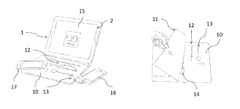
- FIG. 1illustrates a mobile electronic tablet devices case with a built in rechargeable battery and a plurality of charging cables with alternative angle adjustment means
- FIG. 2illustrates the interior panel for retaining and storing a plurality of charging cables
- FIG. 3illustrates the mobile electronic tablet devices case in a closed position
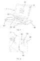
- FIG. 4illustrates the mobile electronic tablet devices case in an open position, with alternative angle adjustment means
- FIG. 5illustrates and the mobile electronic tablet devices case, with an external charging port connect to a mobile phone
- FIG. 6illustrates the mobile electronic tablet devices case in an open position, with multiple external charging ports
- FIG. 7illustrates the mobile electronic tablet devices case in an open position, with multiple charging cables connect to multiple additional devices
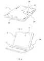
- FIG. 8illustrates the mobile electronic tablet devices case in an open position, with the four corner retaining supports
- FIG. 9illustrates the mobile electronic tablet devices case in an open position, with a perimeter retaining support
- FIG. 10illustrates the mobile electronic tablet devices case in an open position, with a slide in retaining support
- FIG. 11illustrates the mobile electronic tablet devices case in an open position, additional charging cable connected to the battery
- FIG. 12illustrates the internal view of the battery storage portion of the mobile electronic tablet devices case which includes two battery cells and a PCB for controlling charging and providing plugs.
- a table computer case 1 for table computers such as the IPAD, KINDLE, MICROSOFT SURFACE, and other similar devicesis show as one embodiment of the case 1 of the present invention.
- the case 1is a bi-fold design for protecting and charging an electronic tablet device 2 .
- the electronic tablet devices 2include mobile telephones, personal digital assistants, tablets, c-readers, laptops, cameras, portable navigation systems, personal digital music players, handheld game consoles, and the like. It is appreciated that the case 1 of the present invention can be made of any size or configuration in bi-fold or tri-fold embodiment to retain any electronic tablet devices 2 in the market place.
- the two sides 19 and 20are together creating one external surface 21 .
- a loop 22On one end of a side is a loop 22 for retaining a strap 23 that is secured to the opposing side. In a closed position the strap 23 can be inserted into the loop 22 for securing and closing the case 1 .
- Other embodiments for securingsuch as one or more buttons, belts, zippers, etc. are well known in the art and can be used to secure the opposing ends of the two sides.
- a first interior surface 3is used for securing the case the electronic tablet device 2 .
- the electronic tablet devicecan be secure by a compression fitting 8 which extends around the entire surface of the electronic tablet device 2 and secures the electronic tablet device 2 against the interior surface 3 and provides compression force all around the entire surface of the electronic tablet device 2 as show in FIG. 9 .
- straps 4 - 7are placed at each corner of a square or rectangular device can be sued to secure each corner and hold the electronic tablet device 2 against the interior surface 3 .
- FIG. 10illustrates an embodiment where a rigid panel 9 is used in combination with the interior surface 3 to hold the electronic tablet device 2 against the interior surface 3 and have it securely retained within the rigid panel 9 , which would provide greater protection from impacts compared to a fabric design of the other embodiments.
- the rigid panel 9could be made from a plastic material to provide greater impact protection, but also enable enough stretch and bend to secure an electronic tablet device 2 to it by compression forces between the edge of the rigid panel 9 and the edge/side of the electronic tablet device 2 .
- a second interior surface 10is covered with a protective flap 11 for hiding charging cables 12 - 14 and preventing scratches to the electronic tablet device's display screen 15 when the case is in a closed position.
- the case 2When open, the case 2 may be folded in half or have an integrated stand 16 on an outer surface for holding the case 1 and electronic tablet device 2 and display screen 15 at an angle on a flat surface as show in FIG. 4 .
- the flap 11is simply opened to obtain access to use the charging cables 12 - 14 and use the charging cables 12 - 14 are plugged into a corresponding device 17 and 18 .
- the case 1features a portable, rechargeable 3500 mAh-17,000 mAh battery 19 integrated into the case 1 .
- the case's built in rechargeable battery 19delivers 10-90 hours of charging.
- the case 1is a lightweight, stylish synthetic leather case that can provide charging for two or more devices 2 at once via 30-PIN, lightening, and USB connections represented by the charging cables 12 - 14 .
- the case 1keeps all buttons, ports, cameras, and other accessories accessible by providing access holes 20 such as that shown for a typical camera placement on an electronic device 2 , while retaining the electronic tablet device 2 secured.
- the built-in battery 19is quickly and easily recharged via a USB or other charging cable 21 .
- a printed circuit board (PCB)is connected to the battery 19 to control charging and power distribution to other devices connected to the charging cables 12 - 14 .
- FIGS. 4-5an alternative embodiment of the case 1 of the present invention is shown.
- the angle adjustmentis better illustrated, and there is a built in cooling fan, not illustrated.
- the case 1 of this embodimentmay also be rotated for viewing in portrait or landscape positions.
- This case 1also includes a USB charging port 24 for an additional smartphone or table computer, such as an IPAD OR IPHONE, providing additional power as needed to devices 23 external to the case 1 .
- This case 1 embodimentallows the charging of portable electronics on the go, as well as means for keeping the IPAD or other table PC running cooler and extending its life.
- This case 1is typically made from stylish synthetic leather, has a built-in rechargeable battery 19 , cooling face, the battery having 3,500-17,000 mAh and delivering up to 90 hours of charging time for APPLE devices and other smartphones and tablet computers.
- the case 1 of this embodimenthas a harder or less flexible case design and provides for enabling a user to adjust the viewing angle greatly.
- This embodimentillustrates the use of straps 4 - 7 at each of the four corners of the device for attaching and retaining it against a case surface. This design ensures that all device ports such as cameras and buttons remain accessible.
- FIG. 7illustrates the multiple interchangeable tips 24 - 26 and their storage within the case 1 for recharging a plurality of devices 27 - 28 from the case 1 .
- the caseincludes two universal connectors for charging any two devices at once.
- Interchangeable tipsmay include, 30-Pin, Lightning, 2.5 mm, Mini & Micro USBs. Tips are retained in spaces 12 - 14 matching their shape and profile. The openings 12 - 14 in the case 1 provide a compression fit for retaining them until they are desired to be removed.
- FIGS. 6illustrates a case embodiment for charging a KINDLE device 30 .
- This caseuses an ultra slim battery that provides over 10 hours of charging time and is hidden below the soft felt lining of the opposing side of the bi-fold case 29 from where the device is retained. The device is retained by straps 31 - 34 at each of the four corners.
- a USB port 21is provided in the battery portion of the case to charge the KINDLE or any other devices, providing additional power whenever it is needed.
- This caseis easily adaptable to various KINDLE models by altering the size and shape to match that of the other models.
Landscapes
- Telephone Set Structure (AREA)
- Casings For Electric Apparatus (AREA)
Abstract
Description
Claims (17)
Priority Applications (1)
| Application Number | Priority Date | Filing Date | Title |
|---|---|---|---|
| US14/160,501US9439486B2 (en) | 2013-01-21 | 2014-01-21 | Personal electronic carrying and charging device |
Applications Claiming Priority (2)
| Application Number | Priority Date | Filing Date | Title |
|---|---|---|---|
| US201361754717P | 2013-01-21 | 2013-01-21 | |
| US14/160,501US9439486B2 (en) | 2013-01-21 | 2014-01-21 | Personal electronic carrying and charging device |
Publications (2)
| Publication Number | Publication Date |
|---|---|
| US20140202888A1 US20140202888A1 (en) | 2014-07-24 |
| US9439486B2true US9439486B2 (en) | 2016-09-13 |
Family
ID=51206885
Family Applications (1)
| Application Number | Title | Priority Date | Filing Date |
|---|---|---|---|
| US14/160,501Expired - Fee RelatedUS9439486B2 (en) | 2013-01-21 | 2014-01-21 | Personal electronic carrying and charging device |
Country Status (1)
| Country | Link |
|---|---|
| US (1) | US9439486B2 (en) |
Families Citing this family (6)
| Publication number | Priority date | Publication date | Assignee | Title |
|---|---|---|---|---|
| US9160183B2 (en)* | 2012-06-27 | 2015-10-13 | Bren-Tronics, Inc. | Foldable battery charger |
| USD737828S1 (en)* | 2014-02-25 | 2015-09-01 | Stephen J. Albano | Personal organizer folder |
| US9225377B1 (en) | 2014-08-11 | 2015-12-29 | Brookstone Purchasing, Inc. | Modular electronic device case for use with tablet-shaped electronic devices |
| US9544005B2 (en) | 2015-04-15 | 2017-01-10 | Lin L. Wei | Adaptable mobile phone case with battery and charger |
| JP6095736B2 (en) | 2015-07-24 | 2017-03-15 | レノボ・シンガポール・プライベート・リミテッド | Electronic device system, electronic device cover, and electronic device |
| USD788779S1 (en)* | 2015-08-21 | 2017-06-06 | Ty-Flot, Inc. | Tablet pouch with tether |
Citations (9)
| Publication number | Priority date | Publication date | Assignee | Title |
|---|---|---|---|---|
| US2320166A (en)* | 1942-04-13 | 1943-05-25 | Knight Leather Products Co Inc | Case to hold toilet articles |
| US3605961A (en)* | 1969-08-12 | 1971-09-20 | Seward Luggage Mfg Co Inc | Luggage member |
| US6046571A (en)* | 1998-08-21 | 2000-04-04 | Digital Equip Corp | Port replicator with secure integral battery charging cradle |
| US20070177344A1 (en)* | 2006-02-02 | 2007-08-02 | Ben Ming Hsia | Portable personal computer |
| US20070177343A1 (en)* | 2006-02-02 | 2007-08-02 | Ben Ming Hsia | Portable personal computer |
| US20100317412A1 (en)* | 2009-06-15 | 2010-12-16 | Qing Song Tan | Portable phone holder and charger |
| US20100317413A1 (en)* | 2009-06-15 | 2010-12-16 | Qing Song Tan | Portable phone holder and solar charger |
| US20100315041A1 (en)* | 2009-06-15 | 2010-12-16 | Qing Song Tan | Portable phone holder and charger with quick release feature |
| US8281924B2 (en)* | 2010-08-20 | 2012-10-09 | Cyber Acoustics, Llc | Cover for portable electronic device |
- 2014
- 2014-01-21USUS14/160,501patent/US9439486B2/ennot_activeExpired - Fee Related
Patent Citations (9)
| Publication number | Priority date | Publication date | Assignee | Title |
|---|---|---|---|---|
| US2320166A (en)* | 1942-04-13 | 1943-05-25 | Knight Leather Products Co Inc | Case to hold toilet articles |
| US3605961A (en)* | 1969-08-12 | 1971-09-20 | Seward Luggage Mfg Co Inc | Luggage member |
| US6046571A (en)* | 1998-08-21 | 2000-04-04 | Digital Equip Corp | Port replicator with secure integral battery charging cradle |
| US20070177344A1 (en)* | 2006-02-02 | 2007-08-02 | Ben Ming Hsia | Portable personal computer |
| US20070177343A1 (en)* | 2006-02-02 | 2007-08-02 | Ben Ming Hsia | Portable personal computer |
| US20100317412A1 (en)* | 2009-06-15 | 2010-12-16 | Qing Song Tan | Portable phone holder and charger |
| US20100317413A1 (en)* | 2009-06-15 | 2010-12-16 | Qing Song Tan | Portable phone holder and solar charger |
| US20100315041A1 (en)* | 2009-06-15 | 2010-12-16 | Qing Song Tan | Portable phone holder and charger with quick release feature |
| US8281924B2 (en)* | 2010-08-20 | 2012-10-09 | Cyber Acoustics, Llc | Cover for portable electronic device |
Also Published As
| Publication number | Publication date |
|---|---|
| US20140202888A1 (en) | 2014-07-24 |
Similar Documents
| Publication | Publication Date | Title |
|---|---|---|
| US9439486B2 (en) | Personal electronic carrying and charging device | |
| US9225377B1 (en) | Modular electronic device case for use with tablet-shaped electronic devices | |
| US9118195B2 (en) | Mobile communication device housing | |
| US9544005B2 (en) | Adaptable mobile phone case with battery and charger | |
| US20200288832A1 (en) | Protective case for mobile electronic device with storage compartment and pivot stand | |
| JP3182771U (en) | Protective sheath | |
| US20150212544A1 (en) | Mounting Apparatus For Auxiliary Device | |
| EP2438829B1 (en) | Protection cover for portable terminal | |
| EP2757438B1 (en) | An electronic device case | |
| US20160066453A1 (en) | Electronic device case having a kickstand with a removable charger cable | |
| US11303315B2 (en) | Magnetic case and folio for portable personal computing device | |
| US20140139991A1 (en) | Keyboard with slot for orienting a tablet computer during use and tablet computing systems | |
| US20130264241A1 (en) | Electronic device case having variable angle stand | |
| US20150214992A1 (en) | Electronic device cover | |
| CN107040274A (en) | Device housing cover with attached accessory | |
| US20140224676A1 (en) | Low profile protective cover configurable as a stand with integrated battery | |
| US10368622B1 (en) | Glare shield for a mobile telephone | |
| US20100069117A1 (en) | USB enabled mobile phone handset | |
| US20090015192A1 (en) | Portable-electric-appliance protector/power supplier | |
| US20130335003A1 (en) | Personal electronic device carrying case having an integrated battery-powered charger | |
| TWM568551U (en) | Accessory case with multiple-device recharging capabilities | |
| US20150351271A1 (en) | Handheld electronic device carrying case | |
| KR20110025939A (en) | Case for mobile communication terminal | |
| CN105723293A (en) | Electronic device accessory with at least one port | |
| US20140139183A1 (en) | Mobile Device Charger With Support Stand System |
Legal Events
| Date | Code | Title | Description |
|---|---|---|---|
| AS | Assignment | Owner name:INNOVATIVE TECHNOLOGY ELECTRONICS CORP., NEW YORK Free format text:ASSIGNMENT OF ASSIGNORS INTEREST;ASSIGNOR:LIEBLEIN, COREY;REEL/FRAME:035620/0602 Effective date:20150512 | |
| AS | Assignment | Owner name:INNOVATIVE TECHNOLOGY ELECTRONICS CORP., NEW YORK Free format text:ASSIGNMENT OF ASSIGNORS INTEREST;ASSIGNOR:LIEBLEIN, COREY;REEL/FRAME:036510/0402 Effective date:20150908 | |
| AS | Assignment | Owner name:INNOVATIVE TECHNOLOGY ELECTRONICS CORP., NEW YORK Free format text:NUNC PRO TUNC ASSIGNMENT;ASSIGNOR:LIEBLEIN, COREY;REEL/FRAME:038854/0263 Effective date:20160601 Owner name:INNOVATIVE TECHNOLOGY ELECTRONICS CORP., NEW YORK Free format text:NUNC PRO TUNC ASSIGNMENT;ASSIGNOR:LIEBLEIN, COREY;REEL/FRAME:038854/0355 Effective date:20160601 | |
| AS | Assignment | Owner name:INNOVATIVE TECHNOLOGY ELECTRONICS, LLC, DELAWARE Free format text:NUNC PRO TUNC ASSIGNMENT;ASSIGNOR:INNOVATIVE TECHNOLOGY ELECTRONICS CORP.;REEL/FRAME:038881/0767 Effective date:20160601 | |
| STCF | Information on status: patent grant | Free format text:PATENTED CASE | |
| AS | Assignment | Owner name:PNC BANK, NATIONAL ASSOCIATION, PENNSYLVANIA Free format text:SECURITY INTEREST;ASSIGNOR:INNOVATIVE TECHNOLOGY ELECTRONICS, LLC;REEL/FRAME:049785/0602 Effective date:20190703 | |
| FEPP | Fee payment procedure | Free format text:MAINTENANCE FEE REMINDER MAILED (ORIGINAL EVENT CODE: REM.); ENTITY STATUS OF PATENT OWNER: SMALL ENTITY | |
| FEPP | Fee payment procedure | Free format text:SURCHARGE FOR LATE PAYMENT, SMALL ENTITY (ORIGINAL EVENT CODE: M2554); ENTITY STATUS OF PATENT OWNER: SMALL ENTITY | |
| MAFP | Maintenance fee payment | Free format text:PAYMENT OF MAINTENANCE FEE, 4TH YR, SMALL ENTITY (ORIGINAL EVENT CODE: M2551); ENTITY STATUS OF PATENT OWNER: SMALL ENTITY Year of fee payment:4 | |
| FEPP | Fee payment procedure | Free format text:MAINTENANCE FEE REMINDER MAILED (ORIGINAL EVENT CODE: REM.); ENTITY STATUS OF PATENT OWNER: SMALL ENTITY | |
| LAPS | Lapse for failure to pay maintenance fees | Free format text:PATENT EXPIRED FOR FAILURE TO PAY MAINTENANCE FEES (ORIGINAL EVENT CODE: EXP.); ENTITY STATUS OF PATENT OWNER: SMALL ENTITY | |
| STCH | Information on status: patent discontinuation | Free format text:PATENT EXPIRED DUE TO NONPAYMENT OF MAINTENANCE FEES UNDER 37 CFR 1.362 | |
| FP | Lapsed due to failure to pay maintenance fee | Effective date:20240913 |