US9438517B2 - Method and system for identifying matching packets - Google Patents
Method and system for identifying matching packetsDownload PDFInfo
- Publication number
- US9438517B2 US9438517B2US14/067,656US201314067656AUS9438517B2US 9438517 B2US9438517 B2US 9438517B2US 201314067656 AUS201314067656 AUS 201314067656AUS 9438517 B2US9438517 B2US 9438517B2
- Authority
- US
- United States
- Prior art keywords
- packet
- subset
- packets
- header fields
- network
- Prior art date
- Legal status (The legal status is an assumption and is not a legal conclusion. Google has not performed a legal analysis and makes no representation as to the accuracy of the status listed.)
- Expired - Fee Related, expires
Links
- 238000000034methodMethods0.000titleclaimsabstractdescription29
- 239000000523sampleSubstances0.000claimsdescription61
- 230000006870functionEffects0.000claimsdescription3
- 238000005538encapsulationMethods0.000description5
- 230000005540biological transmissionEffects0.000description3
- 230000014509gene expressionEffects0.000description3
- 238000004891communicationMethods0.000description2
- 238000010586diagramMethods0.000description2
- 239000012634fragmentSubstances0.000description2
- 230000001360synchronised effectEffects0.000description2
- 235000008694Humulus lupulusNutrition0.000description1
- 238000007796conventional methodMethods0.000description1
- 239000000284extractSubstances0.000description1
- 230000003287optical effectEffects0.000description1
- 238000010526radical polymerization reactionMethods0.000description1
- 230000004044responseEffects0.000description1
- 238000005070samplingMethods0.000description1
Images


Classifications
- H—ELECTRICITY
- H04—ELECTRIC COMMUNICATION TECHNIQUE
- H04L—TRANSMISSION OF DIGITAL INFORMATION, e.g. TELEGRAPHIC COMMUNICATION
- H04L43/00—Arrangements for monitoring or testing data switching networks
- H04L43/02—Capturing of monitoring data
- H04L43/022—Capturing of monitoring data by sampling
- H—ELECTRICITY
- H04—ELECTRIC COMMUNICATION TECHNIQUE
- H04L—TRANSMISSION OF DIGITAL INFORMATION, e.g. TELEGRAPHIC COMMUNICATION
- H04L43/00—Arrangements for monitoring or testing data switching networks
- H04L43/02—Capturing of monitoring data
- H04L43/026—Capturing of monitoring data using flow identification
- H—ELECTRICITY
- H04—ELECTRIC COMMUNICATION TECHNIQUE
- H04L—TRANSMISSION OF DIGITAL INFORMATION, e.g. TELEGRAPHIC COMMUNICATION
- H04L43/00—Arrangements for monitoring or testing data switching networks
- H04L43/02—Capturing of monitoring data
- H04L43/028—Capturing of monitoring data by filtering
- H—ELECTRICITY
- H04—ELECTRIC COMMUNICATION TECHNIQUE
- H04L—TRANSMISSION OF DIGITAL INFORMATION, e.g. TELEGRAPHIC COMMUNICATION
- H04L43/00—Arrangements for monitoring or testing data switching networks
- H04L43/08—Monitoring or testing based on specific metrics, e.g. QoS, energy consumption or environmental parameters
- H04L43/0852—Delays
- H04L43/0858—One way delays
- H—ELECTRICITY
- H04—ELECTRIC COMMUNICATION TECHNIQUE
- H04L—TRANSMISSION OF DIGITAL INFORMATION, e.g. TELEGRAPHIC COMMUNICATION
- H04L47/00—Traffic control in data switching networks
- H04L47/10—Flow control; Congestion control
- H04L47/11—Identifying congestion
- H04L47/115—Identifying congestion using a dedicated packet
- H—ELECTRICITY
- H04—ELECTRIC COMMUNICATION TECHNIQUE
- H04L—TRANSMISSION OF DIGITAL INFORMATION, e.g. TELEGRAPHIC COMMUNICATION
- H04L47/00—Traffic control in data switching networks
- H04L47/10—Flow control; Congestion control
- H04L47/34—Flow control; Congestion control ensuring sequence integrity, e.g. using sequence numbers
- H—ELECTRICITY
- H04—ELECTRIC COMMUNICATION TECHNIQUE
- H04L—TRANSMISSION OF DIGITAL INFORMATION, e.g. TELEGRAPHIC COMMUNICATION
- H04L69/00—Network arrangements, protocols or services independent of the application payload and not provided for in the other groups of this subclass
- H04L69/22—Parsing or analysis of headers
- H—ELECTRICITY
- H04—ELECTRIC COMMUNICATION TECHNIQUE
- H04L—TRANSMISSION OF DIGITAL INFORMATION, e.g. TELEGRAPHIC COMMUNICATION
- H04L43/00—Arrangements for monitoring or testing data switching networks
- H04L43/02—Capturing of monitoring data
- H04L43/022—Capturing of monitoring data by sampling
- H04L43/024—Capturing of monitoring data by sampling by adaptive sampling
- H—ELECTRICITY
- H04—ELECTRIC COMMUNICATION TECHNIQUE
- H04L—TRANSMISSION OF DIGITAL INFORMATION, e.g. TELEGRAPHIC COMMUNICATION
- H04L43/00—Arrangements for monitoring or testing data switching networks
- H04L43/08—Monitoring or testing based on specific metrics, e.g. QoS, energy consumption or environmental parameters
- H04L43/0852—Delays
- H—ELECTRICITY
- H04—ELECTRIC COMMUNICATION TECHNIQUE
- H04L—TRANSMISSION OF DIGITAL INFORMATION, e.g. TELEGRAPHIC COMMUNICATION
- H04L47/00—Traffic control in data switching networks
- H04L47/10—Flow control; Congestion control
- H04L47/24—Traffic characterised by specific attributes, e.g. priority or QoS
Definitions
- the present inventionrelates to identifying matching packets at different locations in a network. More particularly, the present invention relates to identifying matching packets by comparing packet signatures.
- test packetsare actively inserted into the network, generating additional network traffic which may degrade the quality of service (QoS) over the network.
- QoSquality of service
- the test packetsmay not follow the same routes as existing network traffic, leading to inaccurate results.
- one aspect of the present inventionrelates to a method of identifying matching packets at different locations in a network, comprising: receiving a first plurality of packets at a first location in the network; selecting a first subset of the first plurality of packets in accordance with a filter; receiving a second plurality of packets at a second location in the network; selecting a second subset of the second plurality of packets in accordance with the same filter; parsing each packet in the first and second subsets to extract invariant header fields from an outermost internet protocol (IP) header inwards, until a minimal set of invariant header fields is obtained for that packet that uniquely identifies that packet throughout the network, or until it is determined that such a minimal set of invariant header fields is not obtainable for that packet; computing a packet signature from the minimal set of invariant header fields for each packet in the first and second subsets for which a minimal set of invariant header fields is obtained; comparing the packet signatures to identify matching packets having the same packet signature
- Another aspect of the present inventionrelates to a system for identifying matching packets at different locations in a network, comprising: a first probe for receiving a first plurality of packets at a first location in the network; and for selecting a first subset of the first plurality of packets in accordance with a filter; a second probe for receiving a second plurality of packets at a second location in the network; and for selecting a second subset of the second plurality of packets in accordance with the same filter; and a packet-matching unit for parsing each packet in the first and second subsets to extract invariant header fields from an outermost IP header inwards, until a minimal set of invariant header fields is obtained for that packet that uniquely identifies that packet throughout the network, or until it is determined that such a minimal set of invariant header fields is not obtainable for that packet; for computing a packet signature from the minimal set of invariant header fields for each packet in the first and second subsets for which a minimal set of invariant header fields is
- FIG. 1is a schematic illustration of an exemplary embodiment of a system according to the present invention
- FIG. 2is a flow diagram of an exemplary embodiment of a method of obtaining a minimal set of invariant header fields according to the present invention.
- FIG. 3is a flow diagram of an exemplary embodiment of a method of adjusting a filter according to the present invention.
- the present inventionprovides a method and system for identifying matching packets at different locations in a network. Once matching packets have been identified, latencies between the network locations may be determined. In particular, matching packets may be identified at a plurality of network nodes that share common network traffic to determine hop-by-hop latencies.
- a system 100 for identifying matching packetsincludes a plurality of probes 110 , e.g., 2 to 500 probes, and a packet-matching unit 120 .
- the system 100also includes a packet-routing engine 130 .
- the system 100implements the method of the present invention.
- the probes 110are located at different locations in a network 140 under test, i.e., within the network 140 and/or at the edge of the network 140 .
- the network 140 under testis an Internet protocol (IP)-based network, such as the Internet, a wide area network (WAN), a local area network (LAN), or a mobile network.
- IPInternet protocol
- WANwide area network
- LANlocal area network
- mobile networkTypically, the probes 110 are located at network nodes in the network 140 under test.
- the packet-matching unit 120 and the optional packet-routing engine 130may be located in the network 140 under test or in another network.
- the packet-matching unit 120is in network communication with the probes 110 , optionally, via the packet-routing engine 130 .
- the probes 110may be implemented as hardware, software, or a combination thereof When implemented as hardware, the probes 110 are, preferably, inline unaddressed devices.
- the probes 110may be eavesdropping devices, intelligent packet directors (IPDs), microprobes, transceivers, or SFProbesTM, i.e., modified standard small form-factor pluggable (SFP) transceivers.
- IPDsintelligent packet directors
- microprobesmicroprobes
- transceiversi.e., modified standard small form-factor pluggable
- the probes 110are embodied in non-transitory computer-readable storage media, e.g., memory, and the actions carried out by each probe 110 are executed by the processor of a hardware device, e.g., a network server or a general purpose computer.
- a hardware devicee.g., a network server or a general purpose computer.
- the packet-matching unit 120 and the optional packet-routing engine 130may also be implemented as hardware, software, or a combination thereof.
- the packet-matching unit 120 and the optional packet-routing engine 130are implemented as software embodied in non-transitory computer-readable storage media, e.g., memory, and the actions carried out by each of the packet-matching unit 120 and the optional packet-routing engine 130 are executed by the processor of a hardware device, e.g., a network server or a general purpose computer.
- the probes 110select and capture, i.e., selectively capture, network traffic, as directed by the packet-matching unit 120 .
- Each probe 110receives a plurality of packets from the network 140 under test, usually, bidirectionally, and selects a subset of the plurality for capture in accordance with a filter.
- the selected subset of network trafficincludes at least some packets having different protocol combinations, e.g., different combinations of network, transport, and/or session protocols.
- this selective captureis performed passively, meaning that the selected packets are captured but not altered, and the existing network traffic is not disrupted.
- the probes 110are each programmed with a filter that defines the subset of network traffic to be selectively captured. All of the probes 110 are programmed with the same filter, so that the same packet can potentially be captured on all of the probes 110 at different locations in the network 140 under test. In other words, there should be significant overlap between the subsets of packets captured at each of the probes 110 . For this reason, random sampling cannot be used.
- the filterincludes at least one filter condition based on a header field, typically, an invariant header field, i.e., a header field in a packet that does not vary as the packet traverses the network 140 .
- an invariant header fieldis selected that has a high variance from packet to packet, such as an identifier (ID) or sequence number, e.g., an IP version 4 (IPv4) ID, an authentication header (AH) sequence number, a transmission control protocol (TCP) sequence number, a real-time transport protocol (RTP) sequence number, or a stream control transmission protocol (SCTP) data chunk transmission sequence number (TSN).
- IDidentifier
- IPv4IP version 4
- AHauthentication header
- TCPtransmission control protocol
- RTPreal-time transport protocol
- SCTPstream control transmission protocol
- the filter conditionWhen based on an ID or sequence number, the filter condition, typically, defines the entire ID or sequence-number space or a non-unitary subset thereof, depending on the network traffic load. When the filter condition defines a non-unitary subset of an ID or sequence number space, it is preferable that the filter condition be based on the least significant bits, so that the packet samples are more evenly spaced. For example, a filter condition with the lower 4 bits of the IPv4 ID set to 0001 will capture about 1 out of every 16 IPv4 packets.
- the filteris specified by a filter expression, e.g., a regular expression or pattern, composed of one or more matching expressions, specifying filter conditions, linked by logical operators.
- a filter expressione.g., a regular expression or pattern, composed of one or more matching expressions, specifying filter conditions, linked by logical operators.
- the filteris configured by the packet-matching unit 120 , optionally, via the packet-routing engine 130 .
- An example of a suitable technique for configuring filtersis disclosed in U.S. Pat. No. 7,760,663 to Ilnicki et al, issued on Jul. 20, 2010, which is incorporated herein by reference.
- the initial filter conditionis, typically, set according to a user's requirements, e.g., to capture packets of interest, to capture less than a specified percentage of the network traffic, to capture less than a specified percentage of the link capacity, and/or to capture less than a specified number of packets per time interval.
- the filteris dynamically and adaptively configured by the packet-matching unit 120 to ensure that sufficient potentially matching packets are captured without burdening the network 140 . Filter conditions may be added, removed, or adjusted by the packet-matching unit 120 in accordance with the network traffic load and the number of captured packets, as described in further detail hereafter.
- the probes 110each inspect the packets in the network traffic as they are received to determine whether they match the filter. Typically, the packets are examined at full-duplex line-rate speeds. When a packet matches the filter, that packet is selected and captured, i.e., copied, as it passes through the probe 110 . The captured packet is assigned a capture timestamp that represents the time at which the packet was captured.
- the probes 110are, typically, synchronized with a global time source, such as a global positioning system (GPS), network time protocol (NTP), or IEEE 1588 master clock, as disclosed, for example, in U.S. Pat. No. 7,573,914 to Ilnicki et al., issued on Aug. 11, 2009, and in U.S. Pat. No.
- the capture timestampis added to the captured packet, along with a capture probe ID that identifies the probe 110 at which the packet was captured.
- the captured packetis then forwarded to the packet-matching unit 120 .
- the captured packeti.e., the copy of the packet
- FRPfilter result packet
- the FRPis then inserted back into the network traffic for routing to the packet-matching unit 120 , optionally, via the packet-routing engine 130 , without disrupting the existing network traffic.
- suitable techniques for using FRPsare disclosed in U.S. Pat. No. 7,894,356 to Mottishaw et al., issued on Feb. 22, 2011, in U.S. Patent Application Publication No. 2011/0305149 to Scott et al., published on Dec. 15, 2011, and in U.S. Patent Application Publication No. 2012/0250519 to Stevens et al., published on Oct. 4, 2012, which are incorporated herein by reference.
- the optional packet-routing engine 130facilitates communications between the packet-matching unit 120 and the probes 110 .
- the probes 110may be discovered, configured, and synchronized through the packet-routing engine 130 .
- the optional packet-routing engine 130also facilitates routing of the captured packets from the probes 110 to the packet-matching unit 120 .
- the packet-matching unit 120receives the captured packets, i.e., the selected subset of network traffic, from each probe 110 , optionally, via the packet-routing engine 130 . For efficiency, a packet signature is computed for each of the captured packets. As the captured packets are received, i.e., in real time, the packet-matching unit 120 parses each captured packet to compute a packet signature for that packet. Packets captured at different probes 110 , within a matching window, i.e., a predetermined time interval, having the same packet signature have a high likelihood to be the same packet and are considered to be matching packets. By comparing the packet signatures, matching packets may be identified.
- a matching windowi.e., a predetermined time interval
- matching packetsmay have different outer network encapsulations, e.g., Ethernet, VLAN, and/or multi-protocol label switching (MPLS) encapsulations.
- MPLSmulti-protocol label switching
- matching packetswill maintain the same values in some inner header fields, referred to as invariant header fields, as they traverse the network 140 .
- invariant header fieldsinclude source and destination addresses, IDs, and sequence numbers.
- the packet signatureis computed from a minimal set of invariant header fields, e.g., a minimum set of invariant header fields, that uniquely identifies a particular packet throughout the network 140 within the matching window.
- the minimal setis a small subset of the invariant header fields present in the particular packet, generally, the smallest subset that will uniquely identify the particular packet.
- the minimal setmust be highly likely to vary from packet to packet within the matching window, but must not vary for a particular packet as it traverses the network 140 .
- the matching windowmust be long enough to allow a packet to traverse the network 140 , but short enough to minimize the likelihood of the same signature being computed for different packets.
- the minimal setmust have the properties of (1) being able to uniquely identify a particular packet throughout the network 140 for the lifetime of that packet, and (2) being invariant at different locations in the network 140 . In other words, the minimal set must be distinct and invariant.
- the minimal setdepends on the particular protocol layers, e.g., network, transport, and/or session layers, present in the particular packet, i.e., on the particular protocol combination of that packet.
- minimal setsare predetermined for various protocol combinations.
- the minimal setincludes an IP source address, an IP destination address, and at least one additional invariant header field, such as an ID or a sequence number.
- a minimal set for an IPv4 packetmay consist of an IPv4 source address, an IPv4 destination address, a non-zero IPv4 ID, and an IPv4 fragment offset.
- RRCRequest for Comments
- the IPv4 ID of a packetwhen non-zero, must be unique for that IPv4 address pair for the time the packet will be active in the network 140 .
- the IPv4 IDcan, therefore, be used as part of the minimal set.
- the user datagram protocol (UDP) checksum of a packetis invariant at different locations in the network 140 , it is not guaranteed, or even particularly likely, to vary from packet to packet, and therefore, cannot be used as part of the minimal set for that packet.
- the packet-matching unit 120parses each protocol layer on the fly, i.e., dynamically.
- the packet-matching unit 120parses the captured packet header by header, i.e., layer by layer, from outside to inside. Based on how an outer header is parsed, the packet-matching unit 120 determines the next header to parse and how to parse it, and so on.
- the packet-matching unit 120In attempting to obtain a minimal set, the packet-matching unit 120 ignores the outer network encapsulation and extracts invariant header fields starting from an outermost IP header. If a minimal set is not obtained from the outermost IP header, the packet-matching unit 120 goes on to the next header, and so on. The packet-matching unit 120 proceeds inwards, i.e., deeper into the captured packet, and continues parsing the packet to extract invariant header fields until a minimal set of invariant header fields is obtained for that packet or until it is determined that a minimal set is not obtainable.
- the packet-matching unit 120will determine that a minimal set is not obtainable.
- a minimal setis not obtainable for protocol combinations having no known ID or sequence number that can potentially uniquely identify a particular packet at different network locations, e.g., protocol combinations involving UDP or address resolution protocol (ARP).
- ARPaddress resolution protocol
- a minimal setis not obtainable for UDP/IPv4 packets having an IPv4 ID of zero and no AH on non-well-known UDP ports, because the UDP checksum will be the same if it has the same UDP pseudo header and payload.
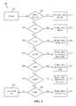
- FIG. 2An exemplary method 200 of obtaining a minimal set of invariant header fields for a particular packet 210 is illustrated in FIG. 2 .
- the minimal set 221consists of the IPv4 source address, the IPv4 destination address, the IPv4 ID, and the IPv4 fragment offset.
- the minimal set 231consists of the IPv4 or IP version 6 (IPv6) source address, the IPv4 or IPv6 destination address, and the AH sequence number.
- IPv6IP version 6
- the minimal set 241consists of the IPv4 or IPv6 source address, the IPv4 or IPv6 destination address, the TCP sequence number, and the TCP acknowledgement number.
- the minimal set 251consists of the IPv4 or IPv6 source address, the IPv4 or IPv6 destination address, the SCTP source port, the SCTP destination port, and the SCTP data chunk TSN.
- the minimal set 261consists of the IPv4 or IPv6 source address, the IPv4 or IPv6 destination address, the GRE key, the GRE sequence number, and the GRE offset.
- the minimal set 271consists of the IPv4 or IPv6 source address, the IPv4 or IPv6 destination address, the IRTP packet type, the IRTP port number, the IRTP sequence number, and the IRTP length.
- the minimal set 281consists of the IPv4 or IPv6 source address, the IPv4 or IPv6 destination address, the RTP sequence number, and the RTP timestamp. Note that, since RTP is not run on well-known ports, the technique of step 280 relies on the RTP ports being provided by a user or discovered through analysis of the real-time transport control protocol (RTCP). Else, at step 290 , it is determined that a minimal set is not obtainable.
- RTCPreal-time transport control protocol
- the packet-matching unit 120For each captured packet for which a minimal set is obtained, the packet-matching unit 120 computes a packet signature from the minimal set of invariant header fields.
- the packet-matching unit 120stores the packet signature of the captured packet in memory, along with the capture timestamp and, preferably, the capture probe ID. Typically, the packet signature is stored in memory along with the captured packet.
- a packet signatureis not computed for captured packets for which a minimal set is not obtained, and these packets will not usually be stored or used for identifying matched packets.
- the packet-matching unit 120compares the packet signatures of the captured packets to identify matching packets, i.e., the same packet captured at different network locations.
- the packet-matching unit 120computes the packet signature by applying a hash function, e.g., MurmurHash 2 , to the minimal set of invariant header fields.
- a hash functione.g., MurmurHash 2
- a 64-bit packet signatureis usually sufficient for uniqueness and efficiency.
- the packet-matching unit 120stores the captured packets in a hash table indexed by the packet signature, referred to as a packet hash table.
- the packet-matching unit 120also forms an ordered queue of references to the captured packets according to capture timestamp, referred to as a packet queue. Both the packet hash table and the packet queue are stored in memory.
- the packet-matching unit 120upon receipt of a new captured packet, its packet signature is computed as described heretofore.
- the packet-matching unit 120inserts the captured packet into the packet hash table by packet signature. As multiple captured packets may have the same packet signature, a hash table implementation is selected that can handle this.
- the packet-matching unit 120also inserts a reference to the captured packet into the packet queue by capture timestamp.
- the packet-matching unit 120receives captured packets over a predetermined time interval, e.g., 0.1 to 1 s, referred to as a matching window.
- the matching windowshould be long enough to encompass the worst-case lifetime of a packet traversing the network 140 , but short enough to not degrade the uniqueness of the packet signature.
- the matching windowis specified by a user and is based on the service level agreement (SLA) for the network 140 under test.
- SLAservice level agreement
- the packet-matching unit 120looks at the head of the packet queue. If the packet reference at the head of the packet queue has been there for the predetermined time interval of the matching window, the packet-matching unit 120 finds all of the captured packets having the same packet signature as the referenced packet in the packet hash table. These packets, referred to as matching packets, represent the same packet captured at different network locations. The packet-matching unit 120 removes the matching packets from the packet hash table and removes the references to the matching packets from the packet queue. If the packet-matching unit 120 does not find any packets having the same packet signature as the referenced packet, that packet is simply discarded.
- the packet-matching unit 120determines latencies for network segments by comparing the capture timestamps of the matching packets.
- the latency for a network segment defined by two probes 110i.e., between the network locations of two probes 110 , is calculated as the absolute difference between the capture timestamps of at least one pair of matching packets captured at the two probes 110 .
- the packet-matching unit 120calculates the average, minimum, and/or maximum latencies for the network segment over a predetermined time interval.
- hop-by-hop latency calculations for a network segment defined by two probes 110are carried out as follows. Over the predetermined time interval of the matching window, e.g., 0.1 to 1 s, the packet-matching unit 120 identifies pairs of matching packets having capture timestamps X 1 and X 2 at the two probes 110 , respectively. The latency for each pair of matching packets is calculated as the absolute difference between the respective capture timestamps, i.e.,
- the average latency for the network segmentis the average of the latencies calculated for the pairs of matching packets, i.e., (sum(
- the minimum and maximum latencies for the network segmentare the minimum and maximum, respectively, of the latencies calculated for the pairs of matching packets identified in the predetermined time interval, i.e., min(
- the packet-matching unit 120may calculate frame delay variations (FDVs), e.g., the average, minimum, and/or maximum FDVs, for the network segment over the predetermined time interval.
- FDVsframe delay variations
- the packet-matching unit 120may similarly calculate one-way end-to-end latencies and FDVs, provided that the topological layout of the probes 110 has been supplied by a user or discovered automatically.
- the packet-matching unit 120may also determine the number of hops between the two probes 110 from the time to live (TTL) fields of the matching packets and/or the topology of the network segment from the network encapsulation, e.g., MPLS labels, VLAN IDs, and/or IP versions, of the matching packets.
- TTLtime to live
- the packet-matching unit 120determines the probes 110 at which the matching packets of the pair were captured, from the capture probe IDs associated with the pair, and the latencies between those probes 110 .
- this analysismay be extended to larger network segments defined by more than two probes 110 by identifying sets of matching packets captured at the probes 110 .
- lost packetsmay be inferred by examining the sets of matching packets.
- packet routes and transit times through the network 140may be determined, and the network topology may be mapped.
- the packet-matching unit 120also, typically, counts the number of captured packets and the number of matching packets for each probe 110 , from which the total number of captured packets and the total number of matching packets for all the probes 110 may be obtained. Preferably, the packet-matching unit 120 also counts the sets, e.g., pairs, of matching packets per IP address pair.
- the packet-matching unit 120stores the results, as they are generated, in memory, typically, in a file, e.g., a text file, or a comma-separated value (CSV) file, or a database.
- a filee.g., a text file, or a comma-separated value (CSV) file, or a database.
- the collected resultsmay be used to adjust the filter used by the probes 110 to capture packets.
- the packet-matching unit 120uses the total number of packets captured at the probes 110 to adjust the filter. If the total number of packets captured over a predetermined time interval is too low, e.g., less than a predetermined threshold, the packet-matching unit 120 will adjust a filter condition to capture more packets, i.e., to be less restrictive, or will add or switch to a filter condition to capture a different kind of network traffic.
- the new filter conditionis based on an invariant header field, in a different protocol layer, that was identified in a captured packet.
- the packet-matching unit 120will adjust a filter condition to capture fewer packets, i.e., to be more restrictive.
- the filteris adjusted continuously in response to real-time network utilization and changes in network traffic patterns. In this way, the filter is dynamically and adaptively configured, i.e., fine-tuned, so that the probes 110 capture as many potentially matching packets as allowable without burdening the network 140 .
- An exemplary method 300 of adjusting the filteris illustrated in FIG. 3 .
- a userPrior to starting selective capture at the probes 110 , a user specifies an upper threshold UT corresponding to the maximum allowable bandwidth for packet capture, e.g., 50% of the network traffic, 5% of the link capacity, or 10 000 packets in a 30 s time interval, as well as a time interval for packet capture, e.g., 0.5 to 5 minutes.
- a corresponding lower threshold (LT)is also set by the user or automatically.
- the packet-matching unit 120sets an initial filter condition at the probes 110 according to these predetermined parameters.
- the initial filter conditionis based on IPv4 ID and captures 1 out of every 1024 IPv4 packets.
- the packet-matching unit 120captures and processes packets over the predetermined time interval.
- the initial filter conditionis adjusted to capture 1 out of every 2048 IPv4 packets.
- the packet-matching unit 120will, generally, stop packet capture immediately once the predetermined upper threshold is reached in the predetermined time interval, so that the threshold is not exceeded.
- the predetermined lower threshold LTi.e., if N ⁇ LT
- a second filter condition based on TCP sequence numberis added, linked by a logical OR operator, that captures 1 out of every 1024 TCP packets.
- the second filter conditionis adjusted to capture 1 out of every 2048 TCP packets.
- a third filter condition based on RTP sequence numberis added, linked by a logical OR operator, that captures 1 out of every 1024 RTP packets.
- the third filter conditionis adjusted to capture 1 out of every 2048 RTP packets.
- the filter conditionis not adjusted.
- the packet-matching unit 120uses the number of sets of matching packets per IP address pair to identify IP address pairs that are associated with the greatest number of sets, i.e., “top talkers”. A user may select one or more of the IP address pairs to track, or the packet-matching unit 120 may make the selection automatically. The packet-matching unit 120 then adjusts the filter accordingly by adding or switching to filter conditions capturing only the selected IP address pairs. For example, if the IP address pair A/B is associated with 100 sets of matching packets captured using an initial 1/1000 filter condition based on IPv4 ID over a predetermined time interval of 1 s, then A is sending about 100 000 packets/s to B.
- the initial filter conditionis adjusted to capture 1 of every 16 IPv4 packets, and a second filter condition is added, linked by a logical AND operator, to capture only packets having the IP address pair A/B.
- the packet-matching unit 120may also use the calculated latencies to adjust the filter. If a network segment has an unusual latency pattern, the packet-matching unit 120 may identify a characteristic, e.g., a VLAN ID, an MPLS label, an IP address pair, an IPv4 type of service, or an IPv6 traffic class, of the matching packets associated with the unusual latency and add or switch to a filter condition based on this characteristic. For example, if analysis shows that matching packets having a VLAN ID of 123 are associated with an unusually high maximum latency, e.g., a maximum latency greater than a predetermined threshold, at a certain time of day, the packet-matching unit 120 will switch to a filter condition capturing only VLAN ID 123 traffic.
- a characteristice.g., a VLAN ID, an MPLS label, an IP address pair, an IPv4 type of service, or an IPv6 traffic class
- a user interfacee.g., a graphical user interface (GUI) may be implemented as part of the packet-matching unit 120 or the optional packet-routing engine 130 , or separately.
- GUIgraphical user interface
- the user interfaceallows a user to select the probes 110 to be used, to set the filters at those probes 110 , and to specify time intervals and thresholds for the packet-matching unit 120 .
- the user interfacealso receives results from the packet-matching unit 120 and provides those results to the user.
Landscapes
- Engineering & Computer Science (AREA)
- Computer Networks & Wireless Communication (AREA)
- Signal Processing (AREA)
- Computer Security & Cryptography (AREA)
- Environmental & Geological Engineering (AREA)
- Data Exchanges In Wide-Area Networks (AREA)
Abstract
Description
Claims (20)
Priority Applications (2)
| Application Number | Priority Date | Filing Date | Title |
|---|---|---|---|
| US14/067,656US9438517B2 (en) | 2012-10-30 | 2013-10-30 | Method and system for identifying matching packets |
| US15/255,348US9736039B2 (en) | 2012-10-30 | 2016-09-02 | Method and system for identifying matching packets |
Applications Claiming Priority (2)
| Application Number | Priority Date | Filing Date | Title |
|---|---|---|---|
| US201261720181P | 2012-10-30 | 2012-10-30 | |
| US14/067,656US9438517B2 (en) | 2012-10-30 | 2013-10-30 | Method and system for identifying matching packets |
Related Child Applications (1)
| Application Number | Title | Priority Date | Filing Date |
|---|---|---|---|
| US15/255,348ContinuationUS9736039B2 (en) | 2012-10-30 | 2016-09-02 | Method and system for identifying matching packets |
Publications (2)
| Publication Number | Publication Date |
|---|---|
| US20140119231A1 US20140119231A1 (en) | 2014-05-01 |
| US9438517B2true US9438517B2 (en) | 2016-09-06 |
Family
ID=50547103
Family Applications (2)
| Application Number | Title | Priority Date | Filing Date |
|---|---|---|---|
| US14/067,656Expired - Fee RelatedUS9438517B2 (en) | 2012-10-30 | 2013-10-30 | Method and system for identifying matching packets |
| US15/255,348ActiveUS9736039B2 (en) | 2012-10-30 | 2016-09-02 | Method and system for identifying matching packets |
Family Applications After (1)
| Application Number | Title | Priority Date | Filing Date |
|---|---|---|---|
| US15/255,348ActiveUS9736039B2 (en) | 2012-10-30 | 2016-09-02 | Method and system for identifying matching packets |
Country Status (3)
| Country | Link |
|---|---|
| US (2) | US9438517B2 (en) |
| EP (1) | EP2915287B1 (en) |
| WO (1) | WO2014070883A2 (en) |
Cited By (3)
| Publication number | Priority date | Publication date | Assignee | Title |
|---|---|---|---|---|
| US9736039B2 (en) | 2012-10-30 | 2017-08-15 | Viavi Solutions Inc. | Method and system for identifying matching packets |
| US10511992B2 (en)* | 2016-12-19 | 2019-12-17 | Qualcomm Incorporated | Prioritizing packets in wireless communications |
| US20220094771A1 (en)* | 2019-02-05 | 2022-03-24 | Casa Systems, Inc. | Methods and apparatus for recovering network association information |
Families Citing this family (27)
| Publication number | Priority date | Publication date | Assignee | Title |
|---|---|---|---|---|
| US9438497B2 (en) | 2013-05-06 | 2016-09-06 | Viavi Solutions Inc. | Method and system for measuring packet loss |
| US9825884B2 (en) | 2013-12-30 | 2017-11-21 | Cavium, Inc. | Protocol independent programmable switch (PIPS) software defined data center networks |
| US10616380B2 (en) | 2014-06-19 | 2020-04-07 | Cavium, Llc | Method of handling large protocol layers for configurable extraction of layer information and an apparatus thereof |
| US9531848B2 (en) | 2014-06-19 | 2016-12-27 | Cavium, Inc. | Method of using generic modification instructions to enable flexible modifications of packets and an apparatus thereof |
| US9516145B2 (en)* | 2014-06-19 | 2016-12-06 | Cavium, Inc. | Method of extracting data from packets and an apparatus thereof |
| US9742694B2 (en) | 2014-06-19 | 2017-08-22 | Cavium, Inc. | Method of dynamically renumbering ports and an apparatus thereof |
| US9438703B2 (en)* | 2014-06-19 | 2016-09-06 | Cavium, Inc. | Method of forming a hash input from packet contents and an apparatus thereof |
| US9497294B2 (en) | 2014-06-19 | 2016-11-15 | Cavium, Inc. | Method of using a unique packet identifier to identify structure of a packet and an apparatus thereof |
| US9888033B1 (en)* | 2014-06-19 | 2018-02-06 | Sonus Networks, Inc. | Methods and apparatus for detecting and/or dealing with denial of service attacks |
| US9961167B2 (en) | 2014-06-19 | 2018-05-01 | Cavium, Inc. | Method of modifying packets to a generic format for enabling programmable modifications and an apparatus thereof |
| US9473601B2 (en)* | 2014-06-19 | 2016-10-18 | Cavium, Inc. | Method of representing a generic format header using continuous bytes and an apparatus thereof |
| US9635146B2 (en) | 2014-06-19 | 2017-04-25 | Cavium, Inc. | Method of using bit vectors to allow expansion and collapse of header layers within packets for enabling flexible modifications and an apparatus thereof |
| US9628385B2 (en) | 2014-06-19 | 2017-04-18 | Cavium, Inc. | Method of identifying internal destinations of networks packets and an apparatus thereof |
| US9531849B2 (en) | 2014-06-19 | 2016-12-27 | Cavium, Inc. | Method of splitting a packet into individual layers for modification and intelligently stitching layers back together after modification and an apparatus thereof |
| US10050833B2 (en) | 2014-06-19 | 2018-08-14 | Cavium, Inc. | Method of reducing latency in a flexible parser and an apparatus thereof |
| US9606781B2 (en) | 2014-11-14 | 2017-03-28 | Cavium, Inc. | Parser engine programming tool for programmable network devices |
| US9800482B2 (en) | 2015-04-29 | 2017-10-24 | Ixia | Signature-based latency extraction systems and related methods for network packet communications |
| EP3398296B1 (en)* | 2015-12-30 | 2021-06-30 | Telecom Italia S.p.A. | Performance measurement in a packet-switched communication network |
| US10298491B2 (en) | 2016-08-25 | 2019-05-21 | Cisco Technology, Inc. | Efficient path detection and validation between endpoints in large datacenters |
| US11546379B2 (en)* | 2017-01-31 | 2023-01-03 | Hewlett Packard Enterprise Development Lp | Providing security for internet of things (IoT) devices |
| US10241680B2 (en)* | 2017-02-28 | 2019-03-26 | Hewlett Packard Enterprise Development Lp | Methods for estimating cost savings using deduplication and compression in a storage system |
| CN107154873B (en)* | 2017-05-05 | 2020-07-21 | 飞思达技术(北京)有限公司 | Resource tree carding system based on V L AN automatic derivation |
| US10966091B1 (en)* | 2017-05-24 | 2021-03-30 | Jonathan Grier | Agile node isolation using packet level non-repudiation for mobile networks |
| US10848420B2 (en)* | 2018-02-12 | 2020-11-24 | Cisco Technology, Inc. | Dynamic forwarding features in network elements |
| TWI739349B (en)* | 2020-03-18 | 2021-09-11 | 瑞昱半導體股份有限公司 | Communication apparatus and method for dynamically adjusting packet detection threshold |
| CN113453307B (en)* | 2020-03-25 | 2024-11-19 | 瑞昱半导体股份有限公司 | Communication device and method for dynamically adjusting packet detection threshold |
| US11681453B2 (en) | 2020-09-23 | 2023-06-20 | Hewlett Packard Enterprise Development Lp | Data deduplication parameter computation |
Citations (36)
| Publication number | Priority date | Publication date | Assignee | Title |
|---|---|---|---|---|
| US5072377A (en)* | 1986-11-19 | 1991-12-10 | Mitsubishi Denki Kabushiki Kaisha | Data driven processor with data pairing apparatus combining a hash memory with counter directional data loops |
| US5321837A (en)* | 1991-10-11 | 1994-06-14 | International Business Machines Corporation | Event handling mechanism having a process and an action association process |
| US5517505A (en) | 1989-09-29 | 1996-05-14 | Motorola, Inc. | Synchronization method and apparatus for a wireless packet network |
| US5521907A (en)* | 1995-04-25 | 1996-05-28 | Visual Networks, Inc. | Method and apparatus for non-intrusive measurement of round trip delay in communications networks |
| WO2000031963A1 (en) | 1998-11-24 | 2000-06-02 | Niksun, Inc. | Apparatus and method for collecting and analyzing communications data |
| WO2001001272A2 (en) | 1999-06-30 | 2001-01-04 | Apptitude, Inc. | Method and apparatus for monitoring traffic in a network |
| EP1130850A2 (en) | 2000-03-01 | 2001-09-05 | Tektronix, Inc. | Non-intrusive measurement of end-to-end network properties |
| US20030135612A1 (en) | 2001-07-17 | 2003-07-17 | Huntington Stephen Glen | Full time network traffic recording systems and methods |
| US20030223367A1 (en) | 2002-03-29 | 2003-12-04 | Shay A. David | Methods for identifying network traffic flows |
| US6873600B1 (en) | 2000-02-04 | 2005-03-29 | At&T Corp. | Consistent sampling for network traffic measurement |
| US6920112B1 (en) | 1998-06-29 | 2005-07-19 | Cisco Technology, Inc. | Sampling packets for network monitoring |
| US6922417B2 (en) | 2000-01-28 | 2005-07-26 | Compuware Corporation | Method and system to calculate network latency, and to display the same field of the invention |
| US20060077906A1 (en) | 2003-09-29 | 2006-04-13 | The Kansai Electric Power Co., Inc. Matsushita Electric Works, Ltd | Path setting method, and network, relay station and parent station employing the path setting method |
| US20060077902A1 (en) | 2004-10-08 | 2006-04-13 | Kannan Naresh K | Methods and apparatus for non-intrusive measurement of delay variation of data traffic on communication networks |
| US7292537B2 (en) | 2002-11-29 | 2007-11-06 | Alcatel Lucent | Measurement architecture to obtain per-hop one-way packet loss and delay in multi-class service networks |
| US20080247331A1 (en) | 2006-11-01 | 2008-10-09 | Cisco Systems, Inc. | Method and Apparatus for High Resolution Passive Network Latency Measurement |
| US20090161547A1 (en)* | 2007-12-20 | 2009-06-25 | Packeteer, Inc. | Compression Mechanisms for Control Plane-Data Plane Processing Architectures |
| US7573914B2 (en) | 2005-05-12 | 2009-08-11 | Agilent Technologies, Inc. | Systems and methods for synchronizing time across networks |
| US7689854B2 (en) | 2006-09-22 | 2010-03-30 | Agilent Technologies, Inc. | Method and apparatus for establishing IEEE 1588 clock synchronization across a network element comprising first and second cooperating smart interface converters wrapping the network element |
| US20100110916A1 (en) | 2008-06-23 | 2010-05-06 | Hart Communication Foundation | Wireless Communication Network Analyzer |
| US7760663B2 (en) | 2004-04-19 | 2010-07-20 | Jds Uniphase Corporation | Packet tracing using dynamic packet filters |
| US7894356B2 (en) | 2005-12-23 | 2011-02-22 | Jds Uniphase Corporation | System and method for measuring network performance using real network traffic |
| EP2298445A1 (en) | 2009-08-19 | 2011-03-23 | King Abdulaziz City for Science and Technology | Hydroconversion process and catalyst used therein |
| US7961635B2 (en) | 2006-05-24 | 2011-06-14 | At&T Intellectual Property I, Lp | Network latency analysis packet and method |
| US20110149966A1 (en)* | 2009-12-21 | 2011-06-23 | Solarflare Communications Inc | Header Processing Engine |
| US20110283140A1 (en) | 2010-05-14 | 2011-11-17 | Jds Uniphase Corporation | Network communication at unaddressed network devices |
| US20110305149A1 (en) | 2010-06-15 | 2011-12-15 | Jds Uniphase Corporation | Method for time aware inline remote mirroring |
| US20120155494A1 (en)* | 2010-12-14 | 2012-06-21 | International Business Machines Corporation | Bidirectional packet flow transformation |
| US20120159132A1 (en)* | 2010-12-16 | 2012-06-21 | International Business Machines Corporation | Accelerating Data Packet Parsing |
| US20120250519A1 (en) | 2011-04-04 | 2012-10-04 | Jds Uniphase Corporation | Unaddressed device communication from within an mpls network |
| US8341297B2 (en) | 2000-07-19 | 2012-12-25 | Akamai Technologies, Inc. | Latencies and weightings in a domain name service (DNS) system |
| US8385212B2 (en) | 2009-12-07 | 2013-02-26 | Symmetricom, Inc. | Method and apparatus for finding latency floor in packet networks |
| US8427966B2 (en) | 2007-10-26 | 2013-04-23 | Jds Uniphase Corporation | Programmable passive probe |
| US20130179821A1 (en) | 2012-01-11 | 2013-07-11 | Samuel M. Bauer | High speed logging system |
| US20130223444A1 (en)* | 2012-02-23 | 2013-08-29 | Christopher D. Liljenstolpe | System and methods for managing network packet forwarding with a controller |
| US8639875B1 (en)* | 2011-09-06 | 2014-01-28 | Netlogic Microsystems, Inc. | Content search system having multiple pipelines |
Family Cites Families (2)
| Publication number | Priority date | Publication date | Assignee | Title |
|---|---|---|---|---|
| US8509072B2 (en)* | 2011-03-07 | 2013-08-13 | Comcast Cable Communications, Llc | Network congestion analysis |
| WO2014070883A2 (en) | 2012-10-30 | 2014-05-08 | Jds Uniphase Corporation | Method and system for identifying matching packets |
- 2013
- 2013-10-30WOPCT/US2013/067497patent/WO2014070883A2/enactiveApplication Filing
- 2013-10-30EPEP13850496.4Apatent/EP2915287B1/ennot_activeNot-in-force
- 2013-10-30USUS14/067,656patent/US9438517B2/ennot_activeExpired - Fee Related
- 2016
- 2016-09-02USUS15/255,348patent/US9736039B2/enactiveActive
Patent Citations (38)
| Publication number | Priority date | Publication date | Assignee | Title |
|---|---|---|---|---|
| US5072377A (en)* | 1986-11-19 | 1991-12-10 | Mitsubishi Denki Kabushiki Kaisha | Data driven processor with data pairing apparatus combining a hash memory with counter directional data loops |
| US5517505A (en) | 1989-09-29 | 1996-05-14 | Motorola, Inc. | Synchronization method and apparatus for a wireless packet network |
| US5321837A (en)* | 1991-10-11 | 1994-06-14 | International Business Machines Corporation | Event handling mechanism having a process and an action association process |
| US5521907A (en)* | 1995-04-25 | 1996-05-28 | Visual Networks, Inc. | Method and apparatus for non-intrusive measurement of round trip delay in communications networks |
| US6920112B1 (en) | 1998-06-29 | 2005-07-19 | Cisco Technology, Inc. | Sampling packets for network monitoring |
| WO2000031963A1 (en) | 1998-11-24 | 2000-06-02 | Niksun, Inc. | Apparatus and method for collecting and analyzing communications data |
| US20040083299A1 (en)* | 1999-06-30 | 2004-04-29 | Dietz Russell S. | Method and apparatus for monitoring traffic in a network |
| WO2001001272A2 (en) | 1999-06-30 | 2001-01-04 | Apptitude, Inc. | Method and apparatus for monitoring traffic in a network |
| US6922417B2 (en) | 2000-01-28 | 2005-07-26 | Compuware Corporation | Method and system to calculate network latency, and to display the same field of the invention |
| US6873600B1 (en) | 2000-02-04 | 2005-03-29 | At&T Corp. | Consistent sampling for network traffic measurement |
| EP1130850A2 (en) | 2000-03-01 | 2001-09-05 | Tektronix, Inc. | Non-intrusive measurement of end-to-end network properties |
| US8341297B2 (en) | 2000-07-19 | 2012-12-25 | Akamai Technologies, Inc. | Latencies and weightings in a domain name service (DNS) system |
| US20030135612A1 (en) | 2001-07-17 | 2003-07-17 | Huntington Stephen Glen | Full time network traffic recording systems and methods |
| US20030223367A1 (en) | 2002-03-29 | 2003-12-04 | Shay A. David | Methods for identifying network traffic flows |
| US7292537B2 (en) | 2002-11-29 | 2007-11-06 | Alcatel Lucent | Measurement architecture to obtain per-hop one-way packet loss and delay in multi-class service networks |
| US20060077906A1 (en) | 2003-09-29 | 2006-04-13 | The Kansai Electric Power Co., Inc. Matsushita Electric Works, Ltd | Path setting method, and network, relay station and parent station employing the path setting method |
| US7760663B2 (en) | 2004-04-19 | 2010-07-20 | Jds Uniphase Corporation | Packet tracing using dynamic packet filters |
| US20060077902A1 (en) | 2004-10-08 | 2006-04-13 | Kannan Naresh K | Methods and apparatus for non-intrusive measurement of delay variation of data traffic on communication networks |
| US7573914B2 (en) | 2005-05-12 | 2009-08-11 | Agilent Technologies, Inc. | Systems and methods for synchronizing time across networks |
| US7894356B2 (en) | 2005-12-23 | 2011-02-22 | Jds Uniphase Corporation | System and method for measuring network performance using real network traffic |
| US7961635B2 (en) | 2006-05-24 | 2011-06-14 | At&T Intellectual Property I, Lp | Network latency analysis packet and method |
| US7689854B2 (en) | 2006-09-22 | 2010-03-30 | Agilent Technologies, Inc. | Method and apparatus for establishing IEEE 1588 clock synchronization across a network element comprising first and second cooperating smart interface converters wrapping the network element |
| US20080247331A1 (en) | 2006-11-01 | 2008-10-09 | Cisco Systems, Inc. | Method and Apparatus for High Resolution Passive Network Latency Measurement |
| US8243599B2 (en) | 2006-11-01 | 2012-08-14 | Cisco Technology, Inc. | Method and apparatus for high resolution passive network latency measurement |
| US8427966B2 (en) | 2007-10-26 | 2013-04-23 | Jds Uniphase Corporation | Programmable passive probe |
| US20090161547A1 (en)* | 2007-12-20 | 2009-06-25 | Packeteer, Inc. | Compression Mechanisms for Control Plane-Data Plane Processing Architectures |
| US20100110916A1 (en) | 2008-06-23 | 2010-05-06 | Hart Communication Foundation | Wireless Communication Network Analyzer |
| EP2298445A1 (en) | 2009-08-19 | 2011-03-23 | King Abdulaziz City for Science and Technology | Hydroconversion process and catalyst used therein |
| US8385212B2 (en) | 2009-12-07 | 2013-02-26 | Symmetricom, Inc. | Method and apparatus for finding latency floor in packet networks |
| US20110149966A1 (en)* | 2009-12-21 | 2011-06-23 | Solarflare Communications Inc | Header Processing Engine |
| US20110283140A1 (en) | 2010-05-14 | 2011-11-17 | Jds Uniphase Corporation | Network communication at unaddressed network devices |
| US20110305149A1 (en) | 2010-06-15 | 2011-12-15 | Jds Uniphase Corporation | Method for time aware inline remote mirroring |
| US20120155494A1 (en)* | 2010-12-14 | 2012-06-21 | International Business Machines Corporation | Bidirectional packet flow transformation |
| US20120159132A1 (en)* | 2010-12-16 | 2012-06-21 | International Business Machines Corporation | Accelerating Data Packet Parsing |
| US20120250519A1 (en) | 2011-04-04 | 2012-10-04 | Jds Uniphase Corporation | Unaddressed device communication from within an mpls network |
| US8639875B1 (en)* | 2011-09-06 | 2014-01-28 | Netlogic Microsystems, Inc. | Content search system having multiple pipelines |
| US20130179821A1 (en) | 2012-01-11 | 2013-07-11 | Samuel M. Bauer | High speed logging system |
| US20130223444A1 (en)* | 2012-02-23 | 2013-08-29 | Christopher D. Liljenstolpe | System and methods for managing network packet forwarding with a controller |
Non-Patent Citations (2)
| Title |
|---|
| Extended European Search Report corresponding to EP 13 85 0496 mailed on Apr. 28, 2016, 11 pages. |
| PCT/US2013/067497 Search Report mailed Apr. 29, 2014. |
Cited By (7)
| Publication number | Priority date | Publication date | Assignee | Title |
|---|---|---|---|---|
| US9736039B2 (en) | 2012-10-30 | 2017-08-15 | Viavi Solutions Inc. | Method and system for identifying matching packets |
| US10511992B2 (en)* | 2016-12-19 | 2019-12-17 | Qualcomm Incorporated | Prioritizing packets in wireless communications |
| TWI736703B (en)* | 2016-12-19 | 2021-08-21 | 美商高通公司 | Prioritizing packets in wireless communications |
| US11252597B2 (en) | 2016-12-19 | 2022-02-15 | Qualcomm Incorporated | Prioritizing packets in wireless communications |
| US20220094771A1 (en)* | 2019-02-05 | 2022-03-24 | Casa Systems, Inc. | Methods and apparatus for recovering network association information |
| US11750725B2 (en)* | 2019-02-05 | 2023-09-05 | Casa Systems, Inc. | Methods and apparatus for recovering network association information |
| US12238193B2 (en)* | 2019-02-05 | 2025-02-25 | Lumine Group Us Holdco Inc. | Methods and apparatus for recovering network association information |
Also Published As
| Publication number | Publication date |
|---|---|
| EP2915287A4 (en) | 2016-05-25 |
| US20160373320A1 (en) | 2016-12-22 |
| EP2915287B1 (en) | 2018-12-05 |
| WO2014070883A2 (en) | 2014-05-08 |
| EP2915287A2 (en) | 2015-09-09 |
| WO2014070883A3 (en) | 2014-06-26 |
| US9736039B2 (en) | 2017-08-15 |
| US20140119231A1 (en) | 2014-05-01 |
Similar Documents
| Publication | Publication Date | Title |
|---|---|---|
| US9736039B2 (en) | Method and system for identifying matching packets | |
| US10063440B2 (en) | Method and system for measuring packet loss | |
| US11848757B2 (en) | In-situ passive performance measurement in a network environment | |
| EP3222006B1 (en) | Passive performance measurement for inline service chaining | |
| EP3222005B1 (en) | Passive performance measurement for inline service chaining | |
| CN104539625B (en) | Network security defense system based on software definition and working method thereof | |
| CN104539594B (en) | SDN architecture, system and working method integrating DDoS threat filtering and routing optimization | |
| WO2019137515A1 (en) | In-band telemetry with limited extra bytes | |
| US9313116B2 (en) | Enhanced retry method | |
| US20050281259A1 (en) | Method of generating a monitoring datagram | |
| CN110431807B (en) | IPTV service quality detection method, device and system | |
| CN104660582B (en) | Software-defined network architecture for DDoS identification, protection and path optimization | |
| US8817792B2 (en) | Data forwarding method, data processing method, system and relevant devices | |
| CN105723657A (en) | Switch, controller, system and link quality detection method | |
| US11102273B2 (en) | Uplink performance management | |
| US9917871B2 (en) | Optimizing media bitrate with explicit network feedback on one client only | |
| WO2018150223A1 (en) | A method and system for identification of traffic flows causing network congestion in centralized control plane networks | |
| CN103685021A (en) | Data transmission method and device | |
| JP6934758B2 (en) | Packet relay device and packet relay method |
Legal Events
| Date | Code | Title | Description |
|---|---|---|---|
| AS | Assignment | Owner name:JDS UNIPHASE CORPORATION, CALIFORNIA Free format text:ASSIGNMENT OF ASSIGNORS INTEREST;ASSIGNORS:CHAN, LAI-CHONG;MOODY, BRIAN;REEL/FRAME:031513/0456 Effective date:20131029 | |
| AS | Assignment | Owner name:VIAVI SOLUTIONS INC., CALIFORNIA Free format text:CHANGE OF NAME;ASSIGNOR:JDS UNIPHASE CORPORATION;REEL/FRAME:036504/0327 Effective date:20150731 | |
| ZAAA | Notice of allowance and fees due | Free format text:ORIGINAL CODE: NOA | |
| ZAAB | Notice of allowance mailed | Free format text:ORIGINAL CODE: MN/=. | |
| ZAAA | Notice of allowance and fees due | Free format text:ORIGINAL CODE: NOA | |
| STCF | Information on status: patent grant | Free format text:PATENTED CASE | |
| FEPP | Fee payment procedure | Free format text:PAYOR NUMBER ASSIGNED (ORIGINAL EVENT CODE: ASPN); ENTITY STATUS OF PATENT OWNER: LARGE ENTITY | |
| MAFP | Maintenance fee payment | Free format text:PAYMENT OF MAINTENANCE FEE, 4TH YEAR, LARGE ENTITY (ORIGINAL EVENT CODE: M1551); ENTITY STATUS OF PATENT OWNER: LARGE ENTITY Year of fee payment:4 | |
| AS | Assignment | Owner name:WELLS FARGO BANK, NATIONAL ASSOCIATION, AS ADMINISTRATIVE AGENT, COLORADO Free format text:SECURITY INTEREST;ASSIGNORS:VIAVI SOLUTIONS INC.;3Z TELECOM, INC.;ACTERNA LLC;AND OTHERS;REEL/FRAME:052729/0321 Effective date:20200519 | |
| AS | Assignment | Owner name:RPC PHOTONICS, INC., NEW YORK Free format text:TERMINATIONS OF SECURITY INTEREST AT REEL 052729, FRAME 0321;ASSIGNOR:WELLS FARGO BANK, NATIONAL ASSOCIATION, AS ADMINISTRATIVE AGENT;REEL/FRAME:058666/0639 Effective date:20211229 Owner name:VIAVI SOLUTIONS INC., CALIFORNIA Free format text:TERMINATIONS OF SECURITY INTEREST AT REEL 052729, FRAME 0321;ASSIGNOR:WELLS FARGO BANK, NATIONAL ASSOCIATION, AS ADMINISTRATIVE AGENT;REEL/FRAME:058666/0639 Effective date:20211229 | |
| FEPP | Fee payment procedure | Free format text:MAINTENANCE FEE REMINDER MAILED (ORIGINAL EVENT CODE: REM.); ENTITY STATUS OF PATENT OWNER: LARGE ENTITY | |
| LAPS | Lapse for failure to pay maintenance fees | Free format text:PATENT EXPIRED FOR FAILURE TO PAY MAINTENANCE FEES (ORIGINAL EVENT CODE: EXP.); ENTITY STATUS OF PATENT OWNER: LARGE ENTITY | |
| STCH | Information on status: patent discontinuation | Free format text:PATENT EXPIRED DUE TO NONPAYMENT OF MAINTENANCE FEES UNDER 37 CFR 1.362 | |
| FP | Lapsed due to failure to pay maintenance fee | Effective date:20240906 |