US9437969B2 - Connection mechanism - Google Patents
Connection mechanismDownload PDFInfo
- Publication number
- US9437969B2 US9437969B2US14/714,584US201514714584AUS9437969B2US 9437969 B2US9437969 B2US 9437969B2US 201514714584 AUS201514714584 AUS 201514714584AUS 9437969 B2US9437969 B2US 9437969B2
- Authority
- US
- United States
- Prior art keywords
- component
- metallic pin
- slot
- components
- metallic
- Prior art date
- Legal status (The legal status is an assumption and is not a legal conclusion. Google has not performed a legal analysis and makes no representation as to the accuracy of the status listed.)
- Active
Links
Images


Classifications
- H—ELECTRICITY
- H01—ELECTRIC ELEMENTS
- H01R—ELECTRICALLY-CONDUCTIVE CONNECTIONS; STRUCTURAL ASSOCIATIONS OF A PLURALITY OF MUTUALLY-INSULATED ELECTRICAL CONNECTING ELEMENTS; COUPLING DEVICES; CURRENT COLLECTORS
- H01R13/00—Details of coupling devices of the kinds covered by groups H01R12/70 or H01R24/00 - H01R33/00
- H01R13/62—Means for facilitating engagement or disengagement of coupling parts or for holding them in engagement
- H01R13/6205—Two-part coupling devices held in engagement by a magnet
- F—MECHANICAL ENGINEERING; LIGHTING; HEATING; WEAPONS; BLASTING
- F16—ENGINEERING ELEMENTS AND UNITS; GENERAL MEASURES FOR PRODUCING AND MAINTAINING EFFECTIVE FUNCTIONING OF MACHINES OR INSTALLATIONS; THERMAL INSULATION IN GENERAL
- F16B—DEVICES FOR FASTENING OR SECURING CONSTRUCTIONAL ELEMENTS OR MACHINE PARTS TOGETHER, e.g. NAILS, BOLTS, CIRCLIPS, CLAMPS, CLIPS OR WEDGES; JOINTS OR JOINTING
- F16B1/00—Devices for securing together, or preventing relative movement between, constructional elements or machine parts
- F—MECHANICAL ENGINEERING; LIGHTING; HEATING; WEAPONS; BLASTING
- F16—ENGINEERING ELEMENTS AND UNITS; GENERAL MEASURES FOR PRODUCING AND MAINTAINING EFFECTIVE FUNCTIONING OF MACHINES OR INSTALLATIONS; THERMAL INSULATION IN GENERAL
- F16B—DEVICES FOR FASTENING OR SECURING CONSTRUCTIONAL ELEMENTS OR MACHINE PARTS TOGETHER, e.g. NAILS, BOLTS, CIRCLIPS, CLAMPS, CLIPS OR WEDGES; JOINTS OR JOINTING
- F16B21/00—Means for preventing relative axial movement of a pin, spigot, shaft or the like and a member surrounding it; Stud-and-socket releasable fastenings
- F16B21/10—Means for preventing relative axial movement of a pin, spigot, shaft or the like and a member surrounding it; Stud-and-socket releasable fastenings by separate parts
- F16B21/12—Means for preventing relative axial movement of a pin, spigot, shaft or the like and a member surrounding it; Stud-and-socket releasable fastenings by separate parts with locking-pins or split-pins thrust into holes
- F—MECHANICAL ENGINEERING; LIGHTING; HEATING; WEAPONS; BLASTING
- F16—ENGINEERING ELEMENTS AND UNITS; GENERAL MEASURES FOR PRODUCING AND MAINTAINING EFFECTIVE FUNCTIONING OF MACHINES OR INSTALLATIONS; THERMAL INSULATION IN GENERAL
- F16B—DEVICES FOR FASTENING OR SECURING CONSTRUCTIONAL ELEMENTS OR MACHINE PARTS TOGETHER, e.g. NAILS, BOLTS, CIRCLIPS, CLAMPS, CLIPS OR WEDGES; JOINTS OR JOINTING
- F16B5/00—Joining sheets or plates, e.g. panels, to one another or to strips or bars parallel to them
- F16B5/06—Joining sheets or plates, e.g. panels, to one another or to strips or bars parallel to them by means of clamps or clips
- F16B5/0607—Joining sheets or plates, e.g. panels, to one another or to strips or bars parallel to them by means of clamps or clips joining sheets or plates to each other
- F16B5/0621—Joining sheets or plates, e.g. panels, to one another or to strips or bars parallel to them by means of clamps or clips joining sheets or plates to each other in parallel relationship
- F16B5/0642—Joining sheets or plates, e.g. panels, to one another or to strips or bars parallel to them by means of clamps or clips joining sheets or plates to each other in parallel relationship the plates being arranged one on top of the other and in full close contact with each other
- F—MECHANICAL ENGINEERING; LIGHTING; HEATING; WEAPONS; BLASTING
- F16—ENGINEERING ELEMENTS AND UNITS; GENERAL MEASURES FOR PRODUCING AND MAINTAINING EFFECTIVE FUNCTIONING OF MACHINES OR INSTALLATIONS; THERMAL INSULATION IN GENERAL
- F16L—PIPES; JOINTS OR FITTINGS FOR PIPES; SUPPORTS FOR PIPES, CABLES OR PROTECTIVE TUBING; MEANS FOR THERMAL INSULATION IN GENERAL
- F16L37/00—Couplings of the quick-acting type
- F16L37/004—Couplings of the quick-acting type using magnets
- F—MECHANICAL ENGINEERING; LIGHTING; HEATING; WEAPONS; BLASTING
- F16—ENGINEERING ELEMENTS AND UNITS; GENERAL MEASURES FOR PRODUCING AND MAINTAINING EFFECTIVE FUNCTIONING OF MACHINES OR INSTALLATIONS; THERMAL INSULATION IN GENERAL
- F16M—FRAMES, CASINGS OR BEDS OF ENGINES, MACHINES OR APPARATUS, NOT SPECIFIC TO ENGINES, MACHINES OR APPARATUS PROVIDED FOR ELSEWHERE; STANDS; SUPPORTS
- F16M13/00—Other supports for positioning apparatus or articles; Means for steadying hand-held apparatus or articles
- F16M13/02—Other supports for positioning apparatus or articles; Means for steadying hand-held apparatus or articles for supporting on, or attaching to, an object, e.g. tree, gate, window-frame, cycle
- H—ELECTRICITY
- H01—ELECTRIC ELEMENTS
- H01F—MAGNETS; INDUCTANCES; TRANSFORMERS; SELECTION OF MATERIALS FOR THEIR MAGNETIC PROPERTIES
- H01F7/00—Magnets
- H01F7/02—Permanent magnets [PM]
- H01F7/0231—Magnetic circuits with PM for power or force generation
- H01F7/0252—PM holding devices
- H01F7/0263—Closures, bags, bands, engagement devices with male and female parts
- H—ELECTRICITY
- H01—ELECTRIC ELEMENTS
- H01R—ELECTRICALLY-CONDUCTIVE CONNECTIONS; STRUCTURAL ASSOCIATIONS OF A PLURALITY OF MUTUALLY-INSULATED ELECTRICAL CONNECTING ELEMENTS; COUPLING DEVICES; CURRENT COLLECTORS
- H01R24/00—Two-part coupling devices, or either of their cooperating parts, characterised by their overall structure
- H01R24/38—Two-part coupling devices, or either of their cooperating parts, characterised by their overall structure having concentrically or coaxially arranged contacts
- F16B2001/0035—
- F—MECHANICAL ENGINEERING; LIGHTING; HEATING; WEAPONS; BLASTING
- F16—ENGINEERING ELEMENTS AND UNITS; GENERAL MEASURES FOR PRODUCING AND MAINTAINING EFFECTIVE FUNCTIONING OF MACHINES OR INSTALLATIONS; THERMAL INSULATION IN GENERAL
- F16B—DEVICES FOR FASTENING OR SECURING CONSTRUCTIONAL ELEMENTS OR MACHINE PARTS TOGETHER, e.g. NAILS, BOLTS, CIRCLIPS, CLAMPS, CLIPS OR WEDGES; JOINTS OR JOINTING
- F16B2200/00—Constructional details of connections not covered for in other groups of this subclass
- F16B2200/83—Use of a magnetic material
- Y—GENERAL TAGGING OF NEW TECHNOLOGICAL DEVELOPMENTS; GENERAL TAGGING OF CROSS-SECTIONAL TECHNOLOGIES SPANNING OVER SEVERAL SECTIONS OF THE IPC; TECHNICAL SUBJECTS COVERED BY FORMER USPC CROSS-REFERENCE ART COLLECTIONS [XRACs] AND DIGESTS
- Y10—TECHNICAL SUBJECTS COVERED BY FORMER USPC
- Y10T—TECHNICAL SUBJECTS COVERED BY FORMER US CLASSIFICATION
- Y10T24/00—Buckles, buttons, clasps, etc.
- Y10T24/32—Buckles, buttons, clasps, etc. having magnetic fastener
- Y10T403/18—
- Y—GENERAL TAGGING OF NEW TECHNOLOGICAL DEVELOPMENTS; GENERAL TAGGING OF CROSS-SECTIONAL TECHNOLOGIES SPANNING OVER SEVERAL SECTIONS OF THE IPC; TECHNICAL SUBJECTS COVERED BY FORMER USPC CROSS-REFERENCE ART COLLECTIONS [XRACs] AND DIGESTS
- Y10—TECHNICAL SUBJECTS COVERED BY FORMER USPC
- Y10T—TECHNICAL SUBJECTS COVERED BY FORMER US CLASSIFICATION
- Y10T403/00—Joints and connections
- Y10T403/59—Manually releaseable latch type
- Y10T403/598—Transversely sliding pin
Definitions
- GPSGlobal Positioning System
- mapping devicesare found as standalone devices or incorporated into mobile telephones or other devices.
- Many peoplecarry tablet or slate computers for accessing the Internet or for running various applications.
- a connection mechanism between two componentsmay use one or more metallic pins that are magnetically extended into one or more slots when the components are engaged. The components are locked in place by the pins extending into the slots during engagement.
- the connection mechanismmay include one or more magnets mounted on either or both components. The magnets may be arranged to attract the components when the components are in the locking orientation and to repel the components when the components are in an unlocked position.
- the connection mechanismmay include electrical connections between the components.
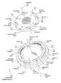
- FIG. 1is a diagram illustration of an embodiment showing two connection components.
- FIG. 2Ais a schematic illustration of a pair of connection components in a first position.
- FIG. 2Bis a schematic illustration of a pair of connection components in a second position.
- FIG. 2Cis a schematic illustration of a pair of connection components in a third position.
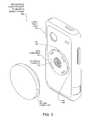
- FIG. 3is a diagram illustration of an embodiment showing the connection components being used for mounting a mobile telephone.
- a connection mechanism or couplermay use metallic pins that are normally retracted into a first component, but may extend into a slot in a second component by magnetic attraction.
- the slotmay be configured so that when the components may be rotated with respect to each other, the pin may be moved back to its retracted position. When retracted, the components may be separated, but when the pin is engaged in the slot, the components may be held together.
- the componentsmay engage each other in different sequences.
- the componentsmay be mated but may be rotated with respect to each other, such that the pin or pins do not align with the slot.
- the pinsmay extend.
- the componentsmay be unlocked by rotating the components with respect to each other.
- the componentsmay be mated such that the pin or pins are aligned with the slots. As the components are mated, the pins may be extended and the components may be locked in place. As with the previous sequence, the components may be unlocked by rotating the components with respect to each other.
- Some embodimentsmay include one or more engagement magnets that may attract the components together.
- the engagement magnetsmay be arrayed such that they attract the components in a locked position but repel the components in an unlocked position. Such embodiments may give a user a tactile feedback when the components are unlocked and locked.
- connection mechanismmay mechanically lock the components together, but may be readily separated by rotating the components. In the locked position, the connection mechanism may transmit forces from one component to the other component.
- the componentsmay also include various connections, such as electrical connections, air or gas connections, liquid connections, or other connections. With access flow or integration points between the components, such embodiments may be useful for connecting various electrical signals, hoses, pipes, or other conduits in an easy to install and easy to remove system.
- FIG. 1is a schematic illustration of an embodiment 100 showing a first and second component.
- FIG. 1is not to scale.
- Embodiment 100illustrates an example of a mating pair of components oriented so that the mating surfaces are shown.
- Embodiment 100illustrates a first component 102 and second component 104 oriented to view the mating surfaces 126 and 154 .
- the first component 102may be flipped over such that the mating surfaces 126 and 154 are touching each other.
- Embodiment 100illustrates an example of a mating pair of components that may be locked in one of four positions. Each of the four locking positions may be 90 degrees from the next. Other embodiments may have one, two, three, four, five, six, or more locking positions.
- the first component 102has a set of pins 106 , 108 , 110 , and 112 that may correspond to the slots 128 and 130 of the second component.
- the second componentmay have additional slots that are not shown.
- the slots 128 and 130may form lips 132 and 134 .
- the pins on the first component 102may be drawn into the slots of the second component 104 by magnets 136 , 138 , 140 , and 142 that may be positioned near the slots. As the two components are engaged, the magnets 136 , 138 , 140 , and 142 may magnetically attract the pins from their retracted position and into an extended position. In the extended position, the pins may extend into the slots and the first component 102 may be locked to the second component 104 .
- the magnets 136 , 138 , 140 , and 142may be located inside the second component 104 but near the various slots.
- the slotsmay be constructed so that when the first component 102 is rotated with respect to the second component 104 , the pins may be forced back into the retracted position. When in the retracted position, the two components may be separated from each other.
- Embodiment 100shows locking positions that may be equally positioned around the primary axes 156 and 158 .
- Embodiment 100further illustrates an embodiment where each pin may be engaged into a corresponding slot in the mating component.
- Other embodimentsmay have the various pins and slots located such that one or more of the locking positions may not engage all of the various pins and slots.
- the second component 104may have more slots than the first component has pins.
- the first component 102may have more pins than the second component 104 has slots.
- the orientation and position of the various pins and slotsmay be such that not all of the pins may be engaged into slots in a locking position.
- the various pins 106 , 108 , 110 , and 112are illustrated as rectangular bars.
- the pinsmay be formed in many different shapes and move in various manners in other embodiments.
- the pinsmay have a circular, square, or other shaped cross-section.
- the pinsmay move linearly.
- Other embodimentsmay use pins that rotate about a hinge point or slide in a curved fashion.
- Embodiment 100shows pins that move in a channel or hole that is perpendicular to the primary axis 156 .
- Other embodimentsmay have a similar channel or hole, but that channel or hole may not be perpendicular to the primary axis 156 .
- the first component 102has an engagement face 124 that is circular in shape which is a revolved surface about the primary axis 156 .
- the engagement face 124may fit against the engagement face 152 of the second component 104 when the two components are mated.
- the engagement face 152 of the second component 104may be a revolved surface about the primary axis 158 .
- the engagement face 124 of the first component 102may be slightly smaller in diameter than the engagement face 152 of the second component 104 .
- the difference in diametersmay vary with different embodiments. In some embodiments, the diameter difference may be on the order of a slip fit, which may be 0.005 in to 0.020 in in some cases. Some embodiments may have a diameter difference of 0.020 in to 0.050 in or larger.
- embodiment 100is an example embodiment where the two components 102 and 104 may be rotated 360 degrees with respect to each other.
- the engagement faces 124 and 152may be sectors of circles and the embodiments may permit the components to rotate only a limited arc with respect to each other. Such embodiments may permit only one, two, three, four, or more locking positions, but may not allow the components to rotate more than the limited arc when the mating surface 126 of the first component 102 is in contact with the mating surface 154 of the second component.
- the two components 102 and 104are illustrated as being outfitted with some engagement magnets.
- the first component 102is illustrated as having magnets 114 , 116 , 118 and 120
- the second component 104is illustrated as having magnets 144 , 146 , 148 , and 150 .
- the engagement magnetsmay be exposed or located below the surface of the various components.
- the various engagement magnetsmay draw the two components together when the components are in a locked position.
- the polarity of the magnetsmay be selected so that when the components are rotated to an unlocked position, the engagement magnets may repel each other, causing the components to repel.
- the engagement magnetsare illustrated as being placed in groups of three.
- the center magnetmay have a different polarity than the two other magnets.
- the corresponding set of magnets on the opposite componentmay be arranged similarly, but so that the sets of magnets attract when the components are in the locking position.
- Embodiment 100illustrates the engagement magnets within the periphery of the engagement faces, but other embodiments may have engagement magnets located outside of the radius of the engagement faces.
- Embodiment 100further illustrates an example embodiment where electrical connections may be made when the two components are engaged.
- the first component 102may have several concentric electrical contacts 122 that may mate with the electrical contacts 160 of the second component 104 .
- the electrical contacts 160may be spring loaded contacts that may slide along the concentric electrical contacts 122 when a user couples and decouples the components.
- Other embodimentsmay have other connections, such as hose connections that may pass gasses or liquids through the components. Such hose connections may be passed through the center of the components along the primary axis is some embodiments. Some embodiments may pass light, including laser light, through the components.
- FIGS. 2A, 2B, and 2Cillustrate embodiments 202 , 204 , and 206 showing three different positions of a first component 208 and a second component 210 .
- Embodiments 202 , 204 , and 206are schematic illustrations of how the components move from an unlocked position to a locked position and are not to scale.
- Embodiment 202illustrates the components in an unlocked position.
- Embodiment 206illustrates the components in a locked position, and embodiment 204 shows the components in between locked and unlocked.
- the locking sequencemay be seen by viewing the embodiments in order from top to bottom.
- the unlocking sequenceoperates in reverse.
- the first component 208is rotated with respect to the second component 210 such that the pin 216 is illustrated as being away from the slot 214 .
- the pin 216is illustrated in a retracted position within the channel 218 .
- the magnetic attraction of the magnet 212may draw the pin 216 out of the channel 218 and into the slot 214 .
- the pin 216may be fully extended into the slot 214 .
- the pin 216may be extended to the locking position by the magnetic attraction provided by the magnet 212 .
- the pinWhen in the locked position, the pin may engage a lip formed by the slot and thereby mechanically restrict the components from being pulled apart.
- a set of engagement magnetsmay help hold the two components in the locked position.
- the first component 208may be rotated to the position shown in embodiment 204 .
- the slot 214may force the pin 216 to retract into the channel 218 .
- the first component 208may be further rotated to the position shown in embodiment 202 .
- the slot 214may force the pin 216 further into the channel 218 and into a retracted position.
- FIG. 3is an illustration of an embodiment 300 showing a mechanical coupler used to mount a mobile phone.
- FIG. 3is not to scale.
- the mechanical couplermay be used in many different applications.
- the couplermay be used to mount a mobile telephone to a holder.
- the holdermay be, for example, mounted on a bicycle handlebar, automobile dashboard, or some other location.
- the mobile telephonemay be mounted in a removable case that includes the mating coupler component so that the mobile telephone may be quickly mounted and removed.
- the first component 302may be mounted to a mobile phone case 310 .
- the second component 304may be mounted to a stand or other mechanism.
- the first component 302is illustrated with pins 306 and 308 , as well as electrical contacts 312 .
- Embodiment 300may provide electrical power and signal connections between the stand (not shown) to which the second component 304 is attached, to the mobile phone held in the case 310 .
Landscapes
- Engineering & Computer Science (AREA)
- General Engineering & Computer Science (AREA)
- Mechanical Engineering (AREA)
- Physics & Mathematics (AREA)
- Electromagnetism (AREA)
- Power Engineering (AREA)
- Details Of Connecting Devices For Male And Female Coupling (AREA)
- Casings For Electric Apparatus (AREA)
Abstract
Description
Claims (18)
Priority Applications (1)
| Application Number | Priority Date | Filing Date | Title |
|---|---|---|---|
| US14/714,584US9437969B2 (en) | 2012-05-08 | 2015-05-18 | Connection mechanism |
Applications Claiming Priority (3)
| Application Number | Priority Date | Filing Date | Title |
|---|---|---|---|
| US13/466,301US8608502B2 (en) | 2012-05-08 | 2012-05-08 | Connection mechanism |
| US14/078,436US9062695B2 (en) | 2012-05-08 | 2013-11-12 | Connection mechanism |
| US14/714,584US9437969B2 (en) | 2012-05-08 | 2015-05-18 | Connection mechanism |
Related Parent Applications (1)
| Application Number | Title | Priority Date | Filing Date |
|---|---|---|---|
| US14/078,436ContinuationUS9062695B2 (en) | 2012-05-08 | 2013-11-12 | Connection mechanism |
Publications (2)
| Publication Number | Publication Date |
|---|---|
| US20150249302A1 US20150249302A1 (en) | 2015-09-03 |
| US9437969B2true US9437969B2 (en) | 2016-09-06 |
Family
ID=49548927
Family Applications (3)
| Application Number | Title | Priority Date | Filing Date |
|---|---|---|---|
| US13/466,301Active2032-06-13US8608502B2 (en) | 2012-05-08 | 2012-05-08 | Connection mechanism |
| US14/078,436Active2032-06-14US9062695B2 (en) | 2012-05-08 | 2013-11-12 | Connection mechanism |
| US14/714,584ActiveUS9437969B2 (en) | 2012-05-08 | 2015-05-18 | Connection mechanism |
Family Applications Before (2)
| Application Number | Title | Priority Date | Filing Date |
|---|---|---|---|
| US13/466,301Active2032-06-13US8608502B2 (en) | 2012-05-08 | 2012-05-08 | Connection mechanism |
| US14/078,436Active2032-06-14US9062695B2 (en) | 2012-05-08 | 2013-11-12 | Connection mechanism |
Country Status (1)
| Country | Link |
|---|---|
| US (3) | US8608502B2 (en) |
Cited By (14)
| Publication number | Priority date | Publication date | Assignee | Title |
|---|---|---|---|---|
| US20160190736A1 (en)* | 2014-12-24 | 2016-06-30 | Samsung Electronics Co., Ltd. | Electric connector |
| US20170266672A1 (en)* | 2016-03-21 | 2017-09-21 | Exel Industries | Coating sprayer, method for assembling and disassembling |
| US20170373420A1 (en)* | 2016-06-23 | 2017-12-28 | Jidai ZHOU | Electrical connector for christmas lamp trees |
| US10104212B2 (en)* | 2017-02-16 | 2018-10-16 | Plantronics, Inc. | Headset with magnetic frictional coupler |
| US20190054694A1 (en)* | 2016-05-12 | 2019-02-21 | Hewlett-Packard Development Company, L.P. | Outlet structure |
| US10431910B2 (en)* | 2017-09-15 | 2019-10-01 | Safran Electrical & Power | Electrical connection device in an aircraft |
| US10492602B2 (en) | 2017-01-26 | 2019-12-03 | Bose Corporation | Electronics enclosure mounting |
| US10795185B1 (en) | 2019-06-13 | 2020-10-06 | NextVPU (Shanghai) Co., Ltd. | Connector, assistive device and wearable device |
| US10989933B2 (en) | 2019-04-18 | 2021-04-27 | NextVPU (Shanghai) Co., Ltd. | Connector, assistive device and wearable device |
| US20220214010A1 (en)* | 2019-07-31 | 2022-07-07 | Peak Design | Mobile device mounting system |
| US11548451B2 (en)* | 2019-07-31 | 2023-01-10 | Peak Design | Mobile device mounting system |
| US11719382B2 (en) | 2021-05-28 | 2023-08-08 | Peak Design | Mobile tripod mounting system |
| US11766144B2 (en)* | 2020-06-12 | 2023-09-26 | Christopher Levi Kraus | Container stability mounting apparatus |
| US11971648B2 (en) | 2019-05-13 | 2024-04-30 | Peak Design | Close-pack, high-aspect-ratio camera tripod |
Families Citing this family (109)
| Publication number | Priority date | Publication date | Assignee | Title |
|---|---|---|---|---|
| JP2011134541A (en)* | 2009-12-24 | 2011-07-07 | Nifco Inc | Connection structure |
| US9300081B2 (en)* | 2010-02-02 | 2016-03-29 | Charles Albert Rudisill | Interposer connectors with magnetic components |
| ITRM20110299A1 (en)* | 2011-06-14 | 2012-12-15 | Fabio Fontana | CONNECTION OR RELEASE SYSTEM OF STACKABLE ELEMENTS. |
| US8608502B2 (en) | 2012-05-08 | 2013-12-17 | Otter Products, Llc | Connection mechanism |
| US20150201723A1 (en) | 2013-02-01 | 2015-07-23 | Treefrog Developments, Inc. | Encasements for an electronic device having a biometric scanner |
| US10680383B2 (en) | 2013-03-14 | 2020-06-09 | Apex Technologies, Inc. | Linear electrode systems for module attachment with non-uniform axial spacing |
| US9611881B2 (en)* | 2013-03-15 | 2017-04-04 | Otter Products, Llc | Releasable mount apparatus and system |
| US20160003270A1 (en) | 2013-03-15 | 2016-01-07 | L. Christopher Franklin | Mounting apparatus |
| TWM461255U (en)* | 2013-04-02 | 2013-09-01 | Hon Hai Prec Ind Co Ltd | Power adapter |
| US9678537B2 (en)* | 2013-04-30 | 2017-06-13 | Victor Kupferstein | Mobile device case and peripheral system |
| USD749554S1 (en)* | 2013-06-20 | 2016-02-16 | Samsung Electronics Co., Ltd. | Cover for mobile phone |
| US10078346B2 (en) | 2013-09-21 | 2018-09-18 | Otter Products, Llc | Magnetic mounting system for electronic device |
| EP3086414B1 (en)* | 2013-09-27 | 2019-08-28 | Siemens Aktiengesellschaft | Connector unit |
| US9281638B2 (en)* | 2013-09-30 | 2016-03-08 | Apple Inc. | Connectors |
| USD746802S1 (en)* | 2013-10-15 | 2016-01-05 | Stratoscientific, Inc. | Electronic device case with stethoscope |
| US9414155B2 (en) | 2013-10-15 | 2016-08-09 | Stratoscientific, Inc. | Acoustic collection system for handheld electronic devices |
| US9602917B2 (en) | 2013-10-15 | 2017-03-21 | Stratoscientific, Inc. | Acoustic collection system for handheld electronic devices |
| WO2015075724A1 (en) | 2013-11-24 | 2015-05-28 | HAMAMA, Yaniv | Slim-form charger for a mobile phone |
| WO2015116355A1 (en) | 2014-01-07 | 2015-08-06 | Otter Products, Llc | Protective enclosure for an electronic device |
| USD776058S1 (en) | 2014-04-17 | 2017-01-10 | Google Inc. | Electrical connector |
| US9419376B1 (en)* | 2014-04-17 | 2016-08-16 | Google Inc. | Multipurpose, electronically versatile connector for wearable electronics |
| JP2017534305A (en)* | 2014-07-08 | 2017-11-24 | リー クリストファー フランクリンLee Christopher FRANKLIN | Mounting device |
| TWM492013U (en)* | 2014-09-04 | 2014-12-11 | Syncmold Entpr Corp | Rotatable supporting frame |
| US20160099095A1 (en)* | 2014-10-06 | 2016-04-07 | I-Blades, Inc. | Releasable magnetic device |
| AU2015342739B2 (en)* | 2014-11-05 | 2021-08-05 | Newell Australia Pty Ltd | Power supply coupler |
| CN104505679B (en)* | 2014-12-03 | 2017-06-06 | 歌尔股份有限公司 | A kind of connector and a kind of implementation method of connector |
| WO2016094652A1 (en)* | 2014-12-11 | 2016-06-16 | Amx Llc | Remote toolless mounting accessory |
| JP6537819B2 (en)* | 2014-12-18 | 2019-07-03 | 日本航空電子工業株式会社 | Connector pair |
| US9613739B2 (en)* | 2014-12-23 | 2017-04-04 | Qualcomm Incorporated | Electromagnetic mating interface |
| USD768121S1 (en)* | 2015-01-02 | 2016-10-04 | Nite Ize, Inc. | Case accessory |
| US9755365B2 (en) | 2015-01-08 | 2017-09-05 | Astronics Advanced Electronic Systems Corp. | Modular socket |
| US9986805B2 (en) | 2015-03-30 | 2018-06-05 | Otter Products, Llc | Protective enclosure for an electronic device |
| US20150207535A1 (en)* | 2015-03-31 | 2015-07-23 | Keith Wilson | Magnetic button phone case |
| US10440588B2 (en)* | 2015-04-24 | 2019-10-08 | Hewlett-Packard Development Company, L.P. | Routing signals based on an orientation of devices with respect to each other |
| CA2993968A1 (en)* | 2015-04-29 | 2016-11-03 | Jeri Archuleta | Magnetic coupling for bulbs and sockets |
| US9800283B2 (en)* | 2015-06-17 | 2017-10-24 | Airo Collective, Inc. | Mobile device holder |
| FR3038460B1 (en)* | 2015-07-01 | 2019-09-13 | Gulplug | ELECTRICAL SOCKET ASSEMBLY |
| US10058155B2 (en) | 2015-07-19 | 2018-08-28 | Otter Products, Llc | Protective case system |
| TWI554708B (en)* | 2015-11-11 | 2016-10-21 | 宣明智 | Affixation Element for Micro Devices and Micro Devices |
| ES2596256B1 (en)* | 2015-12-30 | 2017-10-16 | Jorge GODOY COLOSIMO | Device for fixing objects to surfaces and assembly comprising this device. |
| CN105508778B (en)* | 2016-01-25 | 2017-07-21 | 浙江大学台州研究院 | Pipe connecting structure of water for medical bed |
| DE102016102041B4 (en) | 2016-02-05 | 2022-02-10 | Provertha Connectors, Cables & Solutions Gmbh | Magnetic coding |
| CN205882739U (en)* | 2016-05-18 | 2017-01-11 | 严兵 | Omnipotent cell phone stand that charges of wireless |
| US10159159B2 (en) | 2016-05-27 | 2018-12-18 | Mobile Synergy 26 International Limited | Multifunctional connection systems for various devices and methods of use thereof |
| US20170353779A1 (en)* | 2016-06-01 | 2017-12-07 | Essential Products, Inc. | Wireless audio accessory |
| US10271189B2 (en) | 2016-06-01 | 2019-04-23 | Essential Products, Inc. | Communication between devices and device accessories |
| EP3258222A1 (en)* | 2016-06-16 | 2017-12-20 | Fly By Wire Systems France | A connector arrangement for connecting a sensor module to a vehicle and a method for connecting the sensor module to the vehicle |
| AU2017292403B2 (en)* | 2016-07-06 | 2022-10-13 | Fisher & Paykel Healthcare Limited | Respiratory interface |
| US10908652B2 (en) | 2016-08-19 | 2021-02-02 | Microsoft Technology Licensing, Llc | Modular hinge for a computing device |
| USD858758S1 (en)* | 2016-08-22 | 2019-09-03 | Stratoscientific, Inc. | Electronic device case with stethoscope |
| US10327538B2 (en)* | 2016-08-26 | 2019-06-25 | Hugh D. Alexander | Method and apparatus for supporting and transporting personal portable devices using magnets |
| US20180080598A1 (en)* | 2016-09-20 | 2018-03-22 | Apple Inc. | Counterbalanced display stand |
| TWM538268U (en)* | 2016-10-28 | 2017-03-11 | 飛捷科技股份有限公司 | Mobile electronic device fixing module |
| JP6826878B2 (en)* | 2016-12-19 | 2021-02-10 | 日本航空電子工業株式会社 | Sliding connector |
| US10312652B2 (en) | 2017-04-18 | 2019-06-04 | Amazon Technologies, Inc. | Mounting assembly for an electrically-powered device |
| CN110268361A (en)* | 2017-04-24 | 2019-09-20 | 惠普发展公司有限责任合伙企业 | Low profile tablet computer docks solution |
| CN110574504B (en)* | 2017-06-22 | 2021-04-23 | 惠普发展公司,有限责任合伙企业 | Magnetic components for docking equipment |
| DE102017212150A1 (en)* | 2017-07-14 | 2019-01-17 | Fidlock Gmbh | Magnetic closure with electrical contact |
| USD847805S1 (en)* | 2017-08-31 | 2019-05-07 | Broder Bros., Co. | Mobile device pocket with pop-up stand |
| CN107781592B (en)* | 2017-09-26 | 2020-10-27 | 联想(北京)有限公司 | Rotating device |
| FR3072216B1 (en)* | 2017-10-10 | 2020-10-09 | A Raymond Et Cie | CONNECTION DEVICE INCLUDING A MULTIPOLAR MAGNETIC CIRCUIT |
| CN111225582A (en)* | 2017-10-16 | 2020-06-02 | 凯斯X凯斯有限责任公司 | Rotationally restrained connecting system |
| US10623043B2 (en) | 2018-01-23 | 2020-04-14 | Otter Products, Llc | Protective case for electronic device |
| US10788194B2 (en)* | 2018-01-29 | 2020-09-29 | Heathco Llc | Rotatable light fixture secured to a junction box via a base |
| US11333334B2 (en) | 2018-01-29 | 2022-05-17 | Heathco Llc | Rotatable light fixture secured to a junction box via a base |
| US10890277B2 (en) | 2018-02-28 | 2021-01-12 | Kohler Co. | Articulating faucet with progressive magnetic joint |
| US11408543B2 (en) | 2018-02-28 | 2022-08-09 | Kohler Co. | Articulating faucet |
| US11125365B2 (en) | 2018-02-28 | 2021-09-21 | Kohler Co. | Magnetic joint |
| US10694835B2 (en) | 2018-03-15 | 2020-06-30 | Otter Products, Llc | Protective case for use with device grip |
| US10750844B2 (en) | 2018-03-15 | 2020-08-25 | Otter Products, Llc | Protective case for use with device grip |
| KR102557113B1 (en)* | 2018-04-14 | 2023-07-18 | 가부시키가이샤 아스타리스쿠 | Connectors and Connection Adapters |
| CN110548612B (en) | 2018-06-04 | 2021-09-03 | 科勒公司 | Hinged water tap |
| CN110552401B (en) | 2018-06-04 | 2021-09-03 | 科勒公司 | Hinged water tap |
| US11246233B2 (en)* | 2018-09-07 | 2022-02-08 | Apple Inc. | Magnetic attachment mechanism with safety latch for a desktop display |
| US10579096B1 (en)* | 2018-09-20 | 2020-03-03 | Apple Inc. | Contact design for external accessories |
| TWI732412B (en)* | 2019-01-07 | 2021-07-01 | 鴻海精密工業股份有限公司 | Electronic apparatus and base mount kit thereof |
| US10855826B2 (en)* | 2019-01-10 | 2020-12-01 | Scott Phillip Shaw | Spinning accessory for mobile device |
| ZA201902206B (en)* | 2019-04-09 | 2019-12-18 | Norman Frederick Parkin | A connector for electrically connecting a portable electronic device to an accessory |
| FR3096184B1 (en)* | 2019-05-15 | 2021-07-30 | Gulplug | Three-phase electrical connection system |
| DE102019112724B4 (en)* | 2019-05-15 | 2021-05-12 | Phoenix Contact Gmbh & Co. Kg | Connector |
| US11608929B2 (en) | 2019-05-31 | 2023-03-21 | T-Mobile Usa, Inc. | Device-to-mount rotational coupling mechanism |
| USD897329S1 (en) | 2019-07-02 | 2020-09-29 | Otter Products, Llc | Case for a smartphone |
| USD978022S1 (en)* | 2019-08-16 | 2023-02-14 | Open Style Lab, Inc. | Housing for magnetic garment fastener |
| DE102019135236A1 (en)* | 2019-12-19 | 2021-06-24 | Bayerische Motoren Werke Aktiengesellschaft | Storage device |
| CN111059442B (en)* | 2019-12-31 | 2021-12-24 | 联想(北京)有限公司 | Bearing device |
| CN110985837B (en)* | 2019-12-31 | 2022-01-14 | 联想(北京)有限公司 | Display device and electronic equipment |
| CN111365600B (en) | 2020-03-23 | 2022-08-19 | 联想(北京)有限公司 | Wall hanging structure |
| WO2021204813A1 (en) | 2020-04-07 | 2021-10-14 | Arfaoui Faisel | Connection system for establishing a detachable electrically conductive connection, and connectors |
| US11283215B2 (en)* | 2020-07-13 | 2022-03-22 | Xerox Corporation | Magnetic connector system and method of using |
| US11346514B2 (en) | 2020-09-14 | 2022-05-31 | Heathco Llc | Rotationally adjustable outdoor security light |
| US11231152B1 (en) | 2020-09-14 | 2022-01-25 | Heathco Llc | Variable power supply security light |
| US11280458B1 (en) | 2020-09-14 | 2022-03-22 | Heathco Llc | Mechanical and electrical interface for security light mounting |
| US11211963B1 (en) | 2020-10-15 | 2021-12-28 | Peak Design | Mobile device case system |
| US11722166B2 (en) | 2020-10-15 | 2023-08-08 | Peak Design | Mobile device case system |
| US11724651B2 (en)* | 2020-12-30 | 2023-08-15 | Shahroukh M. Kazempour | Smart phone mount for vehicles |
| US12433391B2 (en) | 2021-03-29 | 2025-10-07 | Otter Products, Llc | Collapsible and extendable device grip |
| US20240088606A1 (en)* | 2021-03-29 | 2024-03-14 | Phoenix Contact Gmbh & Co. Kg | Electrical connector with magnetic locking of housing parts rotatable relative to each other |
| EP4071372A1 (en) | 2021-04-06 | 2022-10-12 | Arfaoui, Faisel | Assembly with mounting thread and connection system for electrical consumers |
| US20220322858A1 (en)* | 2021-04-07 | 2022-10-13 | Charles Macsherry | Container retainer device |
| USD980204S1 (en)* | 2021-05-28 | 2023-03-07 | Popsockets Llc | Phone case with positionable accessory |
| US20230007382A1 (en)* | 2021-06-30 | 2023-01-05 | Epos Group A/S | Headset with detachable arm |
| CN114165684A (en)* | 2021-11-17 | 2022-03-11 | 深圳市泽马蓝科技有限公司 | Bracket component, equipment connecting piece and equipment protective housing |
| EP4446637A4 (en)* | 2022-06-24 | 2025-04-23 | Samsung Electronics Co., Ltd. | DISPLAY DEVICE |
| US11927990B2 (en)* | 2022-07-31 | 2024-03-12 | Lenovo (Singapore) Pte. Ltd. | Computing device |
| DK181677B1 (en)* | 2022-09-05 | 2024-09-18 | Unicontrol Aps | Mounting system and method for releasably attaching a device to a mounting structure attached to a vehicle |
| WO2024090164A1 (en)* | 2022-10-24 | 2024-05-02 | ソニーグループ株式会社 | Magnet device, magnet connection structure, and magnet connection method |
| CN218914503U (en)* | 2022-12-27 | 2023-04-25 | 珠海百亚电子科技有限公司 | Magnetic type mobile equipment installation system |
| NL2035404B1 (en)* | 2023-07-17 | 2025-01-28 | Smarter Living B V | Docking unit, connector unit, and dc power supply assembly |
| DE102024109534B3 (en)* | 2024-04-05 | 2025-07-24 | Bayerische Motoren Werke Aktiengesellschaft | coupling device |
Citations (126)
| Publication number | Priority date | Publication date | Assignee | Title |
|---|---|---|---|---|
| US2121301A (en) | 1936-03-12 | 1938-06-21 | Ractliffe Edwin Merchant | Magnetic lock and key |
| FR935529A (en) | 1946-10-31 | 1948-06-22 | Clasp for handbags and similar items | |
| US2851670A (en) | 1955-06-02 | 1958-09-09 | Empire Prod Inc | Cable connector |
| US3143384A (en) | 1962-09-24 | 1964-08-04 | Empire Prod Inc | Cable connector assembly |
| US3416336A (en) | 1965-12-22 | 1968-12-17 | Liquidonics Inc | Magnetic lock devices |
| US3477261A (en) | 1967-07-11 | 1969-11-11 | Robert Siana | Apparatus for preventing access to a lock mechanism |
| US3480310A (en) | 1967-09-29 | 1969-11-25 | North American Rockwell | Quick detachable coupling |
| US3521216A (en) | 1968-06-19 | 1970-07-21 | Manuel Jerair Tolegian | Magnetic plug and socket assembly |
| US3566637A (en) | 1965-07-31 | 1971-03-02 | Huwil Werke Gmbh | Magnetic lock |
| US3584484A (en) | 1966-11-19 | 1971-06-15 | Huwil Werke Hugo Wallach & Soh | Magnetic lock |
| US3689866A (en) | 1970-09-11 | 1972-09-05 | William Kelly | Heavy duty cable connector |
| US3782147A (en) | 1971-05-11 | 1974-01-01 | Mrt Magnet Regeltechnik Gmbh | Security locks |
| US3786391A (en) | 1972-07-11 | 1974-01-15 | W Mathauser | Magnetic self-aligning electrical connector |
| US3808577A (en) | 1973-03-05 | 1974-04-30 | W Mathauser | Magnetic self-aligning quick-disconnect for a telephone or other communications equipment |
| US3810258A (en) | 1972-07-11 | 1974-05-07 | W Mathauser | Quick connect electrical coupler |
| US3816679A (en) | 1973-07-23 | 1974-06-11 | J Hotchkiss | Magnetically operated electrical connector |
| US3837195A (en) | 1973-02-08 | 1974-09-24 | E Pelto | Magnetic pin lock |
| US3951488A (en) | 1973-04-26 | 1976-04-20 | Kurt Hesse | Plug receptacle for a contact rail adaptor |
| US4285220A (en) | 1977-12-29 | 1981-08-25 | Tomomasa Kajita | Magnetically operable lock |
| US4398404A (en) | 1980-03-10 | 1983-08-16 | Miwa Rokku Kogyo Kabushiki Kaisha | Key disengagement preventive device for magnetic tumbler cylinder locks |
| US4431333A (en) | 1982-04-14 | 1984-02-14 | The United States Of America As Represented By The Administrator Of The National Aeronautics And Space Administration | Apparatus for releasably connecting first and second objects in predetermined space relationship |
| US4627251A (en) | 1984-09-17 | 1986-12-09 | Bhate Suresh K | Combined mechanical and magnetic locking system |
| US4702539A (en) | 1986-04-11 | 1987-10-27 | Tweco Products, Inc. | Cable connector assembly |
| US4823397A (en) | 1988-01-29 | 1989-04-18 | Southern Marine Research, Inc. | Transceiver with moisture resistant cover for thumbwheels and the like |
| US4836256A (en) | 1987-01-30 | 1989-06-06 | Meliconi S.R.L. | Shockproof protective sheath for remote controls, in particular those of television receivers |
| US4845593A (en) | 1988-06-07 | 1989-07-04 | Cam-Lok, Inc. | Safety system for an electrical output panel assembly |
| US4859110A (en) | 1988-09-21 | 1989-08-22 | Neapco, Inc. | Automatic coupling device |
| US4895530A (en) | 1989-02-24 | 1990-01-23 | Molex Incorporated | Quick disconnect automotive battery connector |
| US4940414A (en) | 1988-09-20 | 1990-07-10 | Namsung Electronics Corp. | Antitheft car audio set with removable control box |
| US4963902A (en) | 1988-01-19 | 1990-10-16 | Canon Kabushiki Kaisha | Camera system |
| US4994829A (en) | 1989-07-10 | 1991-02-19 | Nikon Corporation | Waterproof camera and lens mount therefore |
| US5054733A (en) | 1990-02-14 | 1991-10-08 | Shields Michael P | Container support device |
| US5074136A (en) | 1990-02-17 | 1991-12-24 | Kim Young C | Magnetic lock device |
| JPH0561069U (en) | 1992-01-23 | 1993-08-10 | カシオ計算機株式会社 | Storage package for small electronic devices |
| US5359756A (en) | 1993-01-26 | 1994-11-01 | Takata Corporation | Automatic buckling device |
| US5600977A (en) | 1995-10-25 | 1997-02-11 | Pinel Medical Inc. | Magnetic locking device |
| US5685730A (en) | 1996-03-15 | 1997-11-11 | Litton Precision Products International, Inc. | Power connector set with secondary lock |
| US5956986A (en) | 1995-12-11 | 1999-09-28 | R. Berchtold A.G. | Locking device with a cylinder lock and a flat key |
| US5990874A (en) | 1996-08-02 | 1999-11-23 | Matsushita Electric Industrial Co., Ltd. | Protective cover for a portable apparatus touch panel |
| US5996956A (en) | 1997-06-17 | 1999-12-07 | Shawver; Michael | Mounting platform for an electronic device |
| US5996954A (en) | 1997-10-14 | 1999-12-07 | Rosen Products Llc | Stowable support apparatus |
| JP2000341383A (en) | 1999-05-28 | 2000-12-08 | Health Support Japan:Kk | Waterproof cover for portable phone |
| US6179122B1 (en) | 1998-11-12 | 2001-01-30 | Michael L. Moncrief | Protective holder for a portable electronic device |
| US20010000617A1 (en) | 1996-01-05 | 2001-05-03 | Tracy David S. | Self locking bi-directional lock/release fixture |
| US6302617B1 (en) | 1996-08-20 | 2001-10-16 | Gerhard Rumpp | Coupling device for a vehicle |
| US6305588B1 (en) | 1999-03-17 | 2001-10-23 | Mitsubishi Electric France | Releasable coupling for a suspension stud on a wall of a mobile telephone |
| US6305656B1 (en) | 1999-02-26 | 2001-10-23 | Dash-It Usa Inc. | Magnetic coupler and various embodiments thereof |
| WO2002011161A2 (en) | 2000-07-31 | 2002-02-07 | Johan Kruger | Protective cover |
| US6352443B1 (en) | 1999-11-17 | 2002-03-05 | Hirose Electric Co., Ltd. | Lamp socket |
| US6364681B1 (en) | 1998-12-14 | 2002-04-02 | Yazaki Corporation | Connector assembly and method of mounting same |
| US6367297B1 (en) | 1999-07-21 | 2002-04-09 | Mottura Serrature Di Sicurezza S.P.A. | Cylinder lock having magnetically operative biassing means |
| US6409531B1 (en) | 2001-02-12 | 2002-06-25 | Microhelix, Inc. | Easily mated compact connector |
| US20020086559A1 (en) | 2001-01-02 | 2002-07-04 | Furas, S.A. | Safety connector for household table-top electrical appliances |
| US6464524B1 (en) | 1999-07-26 | 2002-10-15 | Angelo Fan Brace Licensing, L.L.C. | Ceiling fan with easy installation features |
| US6481254B1 (en) | 1999-03-24 | 2002-11-19 | Beijing Jinweilide Lock Trade Co., Ltd. | Cylinder lock combined with a magnetic pin and a non-magnetic pin |
| US20030013338A1 (en) | 2000-01-29 | 2003-01-16 | Gerhard Birkenmaier | Electric connector |
| US6514624B2 (en) | 2000-02-18 | 2003-02-04 | Dai Nippon Printing Co., Ltd. | Decorative sheet |
| US6550298B1 (en) | 2001-10-09 | 2003-04-22 | Liang-Chin Su | Lockset keyway cover-up mechanism |
| US6607293B2 (en) | 1999-11-30 | 2003-08-19 | Yazaki Corporation | Rear combination lamp |
| US20040029405A1 (en) | 2000-12-14 | 2004-02-12 | Hermann Neidlein | Electromechanical connecting device |
| US6705580B1 (en) | 2002-12-20 | 2004-03-16 | Daimlerchrysler Corporation | Cup holder for a motor vehicle |
| US6721651B1 (en) | 2002-06-28 | 2004-04-13 | Garmin Ltd. | Rugged, waterproof, navigation device with touch panel |
| US6751552B1 (en) | 2002-06-28 | 2004-06-15 | Garmin Ltd. | Rugged, waterproof, navigation device with touch panel |
| US6760570B1 (en) | 2001-04-16 | 2004-07-06 | Albert Gene Higdon, Jr. | Waterproof radio enclosure |
| US6778388B1 (en) | 2001-07-23 | 2004-08-17 | Garmin Ltd. | Water-resistant electronic enclosure having a heat sink |
| US6780049B1 (en) | 2003-06-11 | 2004-08-24 | D'angelo Carlo Armond | Ceiling fixture light/fan quick connect and release |
| US6785566B1 (en) | 2002-02-04 | 2004-08-31 | Louis Irizarry | Cellular telephone case |
| US6844845B1 (en) | 2003-01-06 | 2005-01-18 | Garmin Ltd. | Waterproof combined global positioning system receiver and two-way radio and method of waterproof enclosure fabrication |
| US6913201B1 (en) | 1998-07-10 | 2005-07-05 | Allflex Usa, Inc. | Housing for portable handheld electronic device |
| US6954405B2 (en) | 1999-10-04 | 2005-10-11 | Diver Entertainment Systems, Inc. | System for housing an audio system in an aquatic environment |
| US6966781B1 (en) | 1996-06-22 | 2005-11-22 | Achim Bullinger | Electromechanical connector |
| US20050279661A1 (en) | 2003-11-12 | 2005-12-22 | Hodges Richard P | Cover for remote control device |
| US6983130B2 (en) | 2002-11-13 | 2006-01-03 | Unitech Electronics Co., Ltd. | Waterproof structure of handheld electronic device |
| US6995976B2 (en) | 2001-11-19 | 2006-02-07 | Otter Products, Llc | Protective membrane for touch screen device |
| US20060086873A1 (en) | 2004-10-27 | 2006-04-27 | E-Lead Electronic Co., Ltd. | Fastening apparatus for a detachable multimedia player of cars |
| US7046230B2 (en) | 2001-10-22 | 2006-05-16 | Apple Computer, Inc. | Touch pad handheld device |
| US7056127B2 (en) | 2004-03-17 | 2006-06-06 | Jamco Corporation | Audio plug |
| US7069063B2 (en) | 2001-06-19 | 2006-06-27 | Nokia Mobile Phones Limited | User changeable mobile phone cover |
| US7077681B2 (en) | 2003-12-03 | 2006-07-18 | Ronald James Behoo | Welding connector |
| US7085542B2 (en) | 2002-05-30 | 2006-08-01 | Motorola, Inc. | Portable device including a replaceable cover |
| US20060231713A1 (en) | 2005-04-15 | 2006-10-19 | Crain Stephen B | Mount system for handheld electrical device |
| US7146701B2 (en) | 2003-01-31 | 2006-12-12 | Neeco-Tron, Inc. | Control housing and method of manufacturing same |
| US7158376B2 (en) | 2001-11-19 | 2007-01-02 | Otter Products, Llc | Protective enclosure for an interactive flat-panel controlled device |
| US7180735B2 (en) | 2001-11-19 | 2007-02-20 | Otter Products, Llc | Protective enclosure and watertight adapter for an interactive flat-panel controlled device |
| US7217059B1 (en) | 1998-03-18 | 2007-05-15 | Telezygology Pty Limited | Fixing and release systems |
| US20070113605A1 (en) | 2003-02-17 | 2007-05-24 | Jesus Lopez | Magnetically controlled locking device |
| US7236588B2 (en) | 2003-12-12 | 2007-06-26 | Nokia Corporation | Interlocking cover for mobile terminals |
| US7264479B1 (en) | 2006-06-02 | 2007-09-04 | Lee Vincent J | Coaxial cable magnetic connector |
| US20070215769A1 (en) | 2006-03-15 | 2007-09-20 | The Boeing Company | Retaining member and method for use with a seat track |
| US7287738B2 (en) | 2000-12-06 | 2007-10-30 | Accessmount Llc | Remotely attachable and separable coupling |
| US7308737B2 (en)* | 2005-02-09 | 2007-12-18 | Washin Optical Co., Ltd. | Magnetically actuated locking mechanism |
| US7311526B2 (en) | 2005-09-26 | 2007-12-25 | Apple Inc. | Magnetic connector for electronic device |
| US7352961B2 (en) | 2004-07-08 | 2008-04-01 | Olympus Corporation | Waterproof housing compatible for a plurality of cameras |
| US20080139005A1 (en) | 2006-12-06 | 2008-06-12 | Hong Fu Jin Precision Industry (Shenzhen) Co., Ltd. | Electric connector assembly |
| US20080199252A1 (en) | 2007-02-21 | 2008-08-21 | Sebastian Frey | Coupling mechanism |
| US7445452B1 (en) | 2007-11-30 | 2008-11-04 | Hon Hai Precision Ind. Co., Ltd. | Electrical interconnection system having magnetic retention device |
| US20080305649A1 (en) | 2005-06-30 | 2008-12-11 | David Didur | Rotatable Magnetic Electrical Connector |
| US7497693B1 (en) | 2007-11-30 | 2009-03-03 | Hon Hai Precision Ind. Co., Ltd. | Electrical interconnection system using magnetic retention |
| US7498546B2 (en) | 2002-04-29 | 2009-03-03 | Focus Products Group, Llc | Detachable breakaway power supply source |
| US7575389B2 (en) | 2005-12-08 | 2009-08-18 | Savannah River Nuclear Solutions, Llc | Magnetic coupling device |
| US20090239392A1 (en) | 2008-03-24 | 2009-09-24 | Kabushiki Kaisha Toshiba | Electronic Apparatus |
| US7621161B2 (en) | 2005-03-24 | 2009-11-24 | Fabio Fontana | Magnetic system for the unlocking of padlocks and locks |
| US7625213B1 (en) | 2008-12-23 | 2009-12-01 | Plastoform Industries Ltd. | Magnetic means for detachably and rotatably connecting components in an audio speaker system |
| US7628632B2 (en) | 2008-04-25 | 2009-12-08 | Casco Products Corporation | Locking mechanism |
| US7632119B1 (en) | 2008-08-11 | 2009-12-15 | Cheng Uei Precision Industry Co., Ltd. | Power adapter |
| US7637746B2 (en) | 2006-06-08 | 2009-12-29 | Nokia Corporation | Magnetic connector for mobile electronic devices |
| US7658613B1 (en) | 2007-01-16 | 2010-02-09 | Griffin Technology Inc | Magnetic connector |
| US7726999B2 (en) | 2007-12-21 | 2010-06-01 | Van-System S.R.L. | Electrical connector set |
| US7740499B1 (en) | 2009-02-11 | 2010-06-22 | Itt Manufacturing Enterprises, Inc. | Electrical connector including a bayonet locking device |
| US20110073608A1 (en) | 2009-09-30 | 2011-03-31 | Otter Products, Llc | Case |
| US7927154B2 (en) | 2008-05-12 | 2011-04-19 | GE Lighting Solutions, LLC | Bi-pin connector and a lamp employing the same |
| US7930004B2 (en) | 2004-09-08 | 2011-04-19 | Belkin International, Inc. | Holder, electrical supply, and RF transmitter unit for electronic devices |
| US8040332B2 (en) | 2005-08-09 | 2011-10-18 | Seiko Epson Corporation | Light scan device and image display device |
| US8040032B2 (en) | 2006-09-25 | 2011-10-18 | Lightsources Inc. | Smooth action, spring loaded, twist locking, radial lugged safety connector for lamp |
| USRE42926E1 (en) | 2001-08-27 | 2011-11-15 | Trompeter Electronics, Inc. | Miniature BNC connector |
| US20120118773A1 (en) | 2010-10-12 | 2012-05-17 | TreeFrog Developments, Inc DBA LifeProof | Housing for encasing an object |
| US20120314354A1 (en) | 2011-06-13 | 2012-12-13 | Treefrog Developments, Inc. Dba Lifeproof. | Housing For Encasing a Tablet Computer |
| US20130042581A1 (en) | 2011-08-17 | 2013-02-21 | Case-Mate, Inc. | Snap-on protective cover for electronic device |
| US20130220841A1 (en) | 2012-01-10 | 2013-08-29 | The Joy Factory, Inc. | Protective casing providing impact absorption and water resistance for portable electronic devices |
| US8569875B2 (en) | 2010-03-05 | 2013-10-29 | Authentec, Inc. | Integrally molded die and bezel structure for fingerprint sensors and the like |
| US20130292269A1 (en) | 2012-05-04 | 2013-11-07 | A.G. Findings & Mfg. Co., Inc. | Mobile device case having tension elements |
| US8608502B2 (en) | 2012-05-08 | 2013-12-17 | Otter Products, Llc | Connection mechanism |
| US20140262848A1 (en) | 2013-03-14 | 2014-09-18 | Incipio Technologies, Inc. | Protective case for mobile device |
| US8863563B2 (en) | 2010-02-26 | 2014-10-21 | Rexnord Industries, Llc | Magnetic lock and key assembly |
| US8912904B2 (en) | 2011-12-06 | 2014-12-16 | Tyco Fire & Security Gmbh | Security tag having magnetically releasable latch |
| US8944826B1 (en) | 2013-07-16 | 2015-02-03 | Curbell Medical Products, Inc. | Magnetic connection for cable assembly of electronic device |
Family Cites Families (1)
| Publication number | Priority date | Publication date | Assignee | Title |
|---|---|---|---|---|
| US3512382A (en)* | 1968-04-17 | 1970-05-19 | Liquidonics Inc | Hybrid lock |
- 2012
- 2012-05-08USUS13/466,301patent/US8608502B2/enactiveActive
- 2013
- 2013-11-12USUS14/078,436patent/US9062695B2/enactiveActive
- 2015
- 2015-05-18USUS14/714,584patent/US9437969B2/enactiveActive
Patent Citations (132)
| Publication number | Priority date | Publication date | Assignee | Title |
|---|---|---|---|---|
| US2121301A (en) | 1936-03-12 | 1938-06-21 | Ractliffe Edwin Merchant | Magnetic lock and key |
| FR935529A (en) | 1946-10-31 | 1948-06-22 | Clasp for handbags and similar items | |
| US2851670A (en) | 1955-06-02 | 1958-09-09 | Empire Prod Inc | Cable connector |
| US3143384A (en) | 1962-09-24 | 1964-08-04 | Empire Prod Inc | Cable connector assembly |
| US3566637A (en) | 1965-07-31 | 1971-03-02 | Huwil Werke Gmbh | Magnetic lock |
| US3416336A (en) | 1965-12-22 | 1968-12-17 | Liquidonics Inc | Magnetic lock devices |
| US3584484A (en) | 1966-11-19 | 1971-06-15 | Huwil Werke Hugo Wallach & Soh | Magnetic lock |
| US3477261A (en) | 1967-07-11 | 1969-11-11 | Robert Siana | Apparatus for preventing access to a lock mechanism |
| US3480310A (en) | 1967-09-29 | 1969-11-25 | North American Rockwell | Quick detachable coupling |
| US3521216A (en) | 1968-06-19 | 1970-07-21 | Manuel Jerair Tolegian | Magnetic plug and socket assembly |
| US3689866A (en) | 1970-09-11 | 1972-09-05 | William Kelly | Heavy duty cable connector |
| US3782147A (en) | 1971-05-11 | 1974-01-01 | Mrt Magnet Regeltechnik Gmbh | Security locks |
| US3786391A (en) | 1972-07-11 | 1974-01-15 | W Mathauser | Magnetic self-aligning electrical connector |
| US3810258A (en) | 1972-07-11 | 1974-05-07 | W Mathauser | Quick connect electrical coupler |
| US3837195A (en) | 1973-02-08 | 1974-09-24 | E Pelto | Magnetic pin lock |
| US3808577A (en) | 1973-03-05 | 1974-04-30 | W Mathauser | Magnetic self-aligning quick-disconnect for a telephone or other communications equipment |
| US3951488A (en) | 1973-04-26 | 1976-04-20 | Kurt Hesse | Plug receptacle for a contact rail adaptor |
| US3816679A (en) | 1973-07-23 | 1974-06-11 | J Hotchkiss | Magnetically operated electrical connector |
| US4285220A (en) | 1977-12-29 | 1981-08-25 | Tomomasa Kajita | Magnetically operable lock |
| US4398404A (en) | 1980-03-10 | 1983-08-16 | Miwa Rokku Kogyo Kabushiki Kaisha | Key disengagement preventive device for magnetic tumbler cylinder locks |
| US4431333A (en) | 1982-04-14 | 1984-02-14 | The United States Of America As Represented By The Administrator Of The National Aeronautics And Space Administration | Apparatus for releasably connecting first and second objects in predetermined space relationship |
| US4627251A (en) | 1984-09-17 | 1986-12-09 | Bhate Suresh K | Combined mechanical and magnetic locking system |
| US4702539A (en) | 1986-04-11 | 1987-10-27 | Tweco Products, Inc. | Cable connector assembly |
| US4836256A (en) | 1987-01-30 | 1989-06-06 | Meliconi S.R.L. | Shockproof protective sheath for remote controls, in particular those of television receivers |
| US4963902A (en) | 1988-01-19 | 1990-10-16 | Canon Kabushiki Kaisha | Camera system |
| US4823397A (en) | 1988-01-29 | 1989-04-18 | Southern Marine Research, Inc. | Transceiver with moisture resistant cover for thumbwheels and the like |
| US4845593A (en) | 1988-06-07 | 1989-07-04 | Cam-Lok, Inc. | Safety system for an electrical output panel assembly |
| US4940414A (en) | 1988-09-20 | 1990-07-10 | Namsung Electronics Corp. | Antitheft car audio set with removable control box |
| US4859110A (en) | 1988-09-21 | 1989-08-22 | Neapco, Inc. | Automatic coupling device |
| US4895530A (en) | 1989-02-24 | 1990-01-23 | Molex Incorporated | Quick disconnect automotive battery connector |
| US4994829A (en) | 1989-07-10 | 1991-02-19 | Nikon Corporation | Waterproof camera and lens mount therefore |
| US5054733A (en) | 1990-02-14 | 1991-10-08 | Shields Michael P | Container support device |
| US5074136A (en) | 1990-02-17 | 1991-12-24 | Kim Young C | Magnetic lock device |
| JPH0561069U (en) | 1992-01-23 | 1993-08-10 | カシオ計算機株式会社 | Storage package for small electronic devices |
| US5359756A (en) | 1993-01-26 | 1994-11-01 | Takata Corporation | Automatic buckling device |
| US5600977A (en) | 1995-10-25 | 1997-02-11 | Pinel Medical Inc. | Magnetic locking device |
| US5956986A (en) | 1995-12-11 | 1999-09-28 | R. Berchtold A.G. | Locking device with a cylinder lock and a flat key |
| US20010000617A1 (en) | 1996-01-05 | 2001-05-03 | Tracy David S. | Self locking bi-directional lock/release fixture |
| US5685730A (en) | 1996-03-15 | 1997-11-11 | Litton Precision Products International, Inc. | Power connector set with secondary lock |
| US6966781B1 (en) | 1996-06-22 | 2005-11-22 | Achim Bullinger | Electromechanical connector |
| US5990874A (en) | 1996-08-02 | 1999-11-23 | Matsushita Electric Industrial Co., Ltd. | Protective cover for a portable apparatus touch panel |
| US6302617B1 (en) | 1996-08-20 | 2001-10-16 | Gerhard Rumpp | Coupling device for a vehicle |
| US5996956A (en) | 1997-06-17 | 1999-12-07 | Shawver; Michael | Mounting platform for an electronic device |
| US5996954A (en) | 1997-10-14 | 1999-12-07 | Rosen Products Llc | Stowable support apparatus |
| US7217059B1 (en) | 1998-03-18 | 2007-05-15 | Telezygology Pty Limited | Fixing and release systems |
| US6913201B1 (en) | 1998-07-10 | 2005-07-05 | Allflex Usa, Inc. | Housing for portable handheld electronic device |
| US6179122B1 (en) | 1998-11-12 | 2001-01-30 | Michael L. Moncrief | Protective holder for a portable electronic device |
| US6364681B1 (en) | 1998-12-14 | 2002-04-02 | Yazaki Corporation | Connector assembly and method of mounting same |
| US6305656B1 (en) | 1999-02-26 | 2001-10-23 | Dash-It Usa Inc. | Magnetic coupler and various embodiments thereof |
| US6305588B1 (en) | 1999-03-17 | 2001-10-23 | Mitsubishi Electric France | Releasable coupling for a suspension stud on a wall of a mobile telephone |
| US6481254B1 (en) | 1999-03-24 | 2002-11-19 | Beijing Jinweilide Lock Trade Co., Ltd. | Cylinder lock combined with a magnetic pin and a non-magnetic pin |
| JP2000341383A (en) | 1999-05-28 | 2000-12-08 | Health Support Japan:Kk | Waterproof cover for portable phone |
| US6367297B1 (en) | 1999-07-21 | 2002-04-09 | Mottura Serrature Di Sicurezza S.P.A. | Cylinder lock having magnetically operative biassing means |
| US6464524B1 (en) | 1999-07-26 | 2002-10-15 | Angelo Fan Brace Licensing, L.L.C. | Ceiling fan with easy installation features |
| US6954405B2 (en) | 1999-10-04 | 2005-10-11 | Diver Entertainment Systems, Inc. | System for housing an audio system in an aquatic environment |
| US6352443B1 (en) | 1999-11-17 | 2002-03-05 | Hirose Electric Co., Ltd. | Lamp socket |
| US6607293B2 (en) | 1999-11-30 | 2003-08-19 | Yazaki Corporation | Rear combination lamp |
| US20030013338A1 (en) | 2000-01-29 | 2003-01-16 | Gerhard Birkenmaier | Electric connector |
| US6685493B2 (en) | 2000-01-29 | 2004-02-03 | Zf Friedrichshafen Ag | Electric connector |
| US6514624B2 (en) | 2000-02-18 | 2003-02-04 | Dai Nippon Printing Co., Ltd. | Decorative sheet |
| WO2002011161A2 (en) | 2000-07-31 | 2002-02-07 | Johan Kruger | Protective cover |
| US7287738B2 (en) | 2000-12-06 | 2007-10-30 | Accessmount Llc | Remotely attachable and separable coupling |
| US20040029405A1 (en) | 2000-12-14 | 2004-02-12 | Hermann Neidlein | Electromechanical connecting device |
| US20020086559A1 (en) | 2001-01-02 | 2002-07-04 | Furas, S.A. | Safety connector for household table-top electrical appliances |
| US6409531B1 (en) | 2001-02-12 | 2002-06-25 | Microhelix, Inc. | Easily mated compact connector |
| US6760570B1 (en) | 2001-04-16 | 2004-07-06 | Albert Gene Higdon, Jr. | Waterproof radio enclosure |
| US7069063B2 (en) | 2001-06-19 | 2006-06-27 | Nokia Mobile Phones Limited | User changeable mobile phone cover |
| US6778388B1 (en) | 2001-07-23 | 2004-08-17 | Garmin Ltd. | Water-resistant electronic enclosure having a heat sink |
| USRE42926E1 (en) | 2001-08-27 | 2011-11-15 | Trompeter Electronics, Inc. | Miniature BNC connector |
| US6550298B1 (en) | 2001-10-09 | 2003-04-22 | Liang-Chin Su | Lockset keyway cover-up mechanism |
| US7046230B2 (en) | 2001-10-22 | 2006-05-16 | Apple Computer, Inc. | Touch pad handheld device |
| US7180735B2 (en) | 2001-11-19 | 2007-02-20 | Otter Products, Llc | Protective enclosure and watertight adapter for an interactive flat-panel controlled device |
| US6995976B2 (en) | 2001-11-19 | 2006-02-07 | Otter Products, Llc | Protective membrane for touch screen device |
| US7158376B2 (en) | 2001-11-19 | 2007-01-02 | Otter Products, Llc | Protective enclosure for an interactive flat-panel controlled device |
| US6785566B1 (en) | 2002-02-04 | 2004-08-31 | Louis Irizarry | Cellular telephone case |
| US7498546B2 (en) | 2002-04-29 | 2009-03-03 | Focus Products Group, Llc | Detachable breakaway power supply source |
| US7085542B2 (en) | 2002-05-30 | 2006-08-01 | Motorola, Inc. | Portable device including a replaceable cover |
| US6751552B1 (en) | 2002-06-28 | 2004-06-15 | Garmin Ltd. | Rugged, waterproof, navigation device with touch panel |
| US6721651B1 (en) | 2002-06-28 | 2004-04-13 | Garmin Ltd. | Rugged, waterproof, navigation device with touch panel |
| US6983130B2 (en) | 2002-11-13 | 2006-01-03 | Unitech Electronics Co., Ltd. | Waterproof structure of handheld electronic device |
| US6705580B1 (en) | 2002-12-20 | 2004-03-16 | Daimlerchrysler Corporation | Cup holder for a motor vehicle |
| US6844845B1 (en) | 2003-01-06 | 2005-01-18 | Garmin Ltd. | Waterproof combined global positioning system receiver and two-way radio and method of waterproof enclosure fabrication |
| US7146701B2 (en) | 2003-01-31 | 2006-12-12 | Neeco-Tron, Inc. | Control housing and method of manufacturing same |
| US20070113605A1 (en) | 2003-02-17 | 2007-05-24 | Jesus Lopez | Magnetically controlled locking device |
| US6780049B1 (en) | 2003-06-11 | 2004-08-24 | D'angelo Carlo Armond | Ceiling fixture light/fan quick connect and release |
| US20050279661A1 (en) | 2003-11-12 | 2005-12-22 | Hodges Richard P | Cover for remote control device |
| US7077681B2 (en) | 2003-12-03 | 2006-07-18 | Ronald James Behoo | Welding connector |
| US7236588B2 (en) | 2003-12-12 | 2007-06-26 | Nokia Corporation | Interlocking cover for mobile terminals |
| US7056127B2 (en) | 2004-03-17 | 2006-06-06 | Jamco Corporation | Audio plug |
| US7352961B2 (en) | 2004-07-08 | 2008-04-01 | Olympus Corporation | Waterproof housing compatible for a plurality of cameras |
| US7930004B2 (en) | 2004-09-08 | 2011-04-19 | Belkin International, Inc. | Holder, electrical supply, and RF transmitter unit for electronic devices |
| US20060086873A1 (en) | 2004-10-27 | 2006-04-27 | E-Lead Electronic Co., Ltd. | Fastening apparatus for a detachable multimedia player of cars |
| US7308737B2 (en)* | 2005-02-09 | 2007-12-18 | Washin Optical Co., Ltd. | Magnetically actuated locking mechanism |
| US7621161B2 (en) | 2005-03-24 | 2009-11-24 | Fabio Fontana | Magnetic system for the unlocking of padlocks and locks |
| US20060231713A1 (en) | 2005-04-15 | 2006-10-19 | Crain Stephen B | Mount system for handheld electrical device |
| US20080305649A1 (en) | 2005-06-30 | 2008-12-11 | David Didur | Rotatable Magnetic Electrical Connector |
| US8040332B2 (en) | 2005-08-09 | 2011-10-18 | Seiko Epson Corporation | Light scan device and image display device |
| US7311526B2 (en) | 2005-09-26 | 2007-12-25 | Apple Inc. | Magnetic connector for electronic device |
| US7517222B2 (en) | 2005-09-26 | 2009-04-14 | Apple Inc. | Magnetic connector for electronic device |
| US7575389B2 (en) | 2005-12-08 | 2009-08-18 | Savannah River Nuclear Solutions, Llc | Magnetic coupling device |
| US20070215769A1 (en) | 2006-03-15 | 2007-09-20 | The Boeing Company | Retaining member and method for use with a seat track |
| US7264479B1 (en) | 2006-06-02 | 2007-09-04 | Lee Vincent J | Coaxial cable magnetic connector |
| US7637746B2 (en) | 2006-06-08 | 2009-12-29 | Nokia Corporation | Magnetic connector for mobile electronic devices |
| US8040032B2 (en) | 2006-09-25 | 2011-10-18 | Lightsources Inc. | Smooth action, spring loaded, twist locking, radial lugged safety connector for lamp |
| US20080139005A1 (en) | 2006-12-06 | 2008-06-12 | Hong Fu Jin Precision Industry (Shenzhen) Co., Ltd. | Electric connector assembly |
| US7658613B1 (en) | 2007-01-16 | 2010-02-09 | Griffin Technology Inc | Magnetic connector |
| US20080199252A1 (en) | 2007-02-21 | 2008-08-21 | Sebastian Frey | Coupling mechanism |
| US7871218B2 (en) | 2007-02-21 | 2011-01-18 | Karl Storz Gmbh & Co. Kg | Coupling mechanism |
| US7497693B1 (en) | 2007-11-30 | 2009-03-03 | Hon Hai Precision Ind. Co., Ltd. | Electrical interconnection system using magnetic retention |
| US7445452B1 (en) | 2007-11-30 | 2008-11-04 | Hon Hai Precision Ind. Co., Ltd. | Electrical interconnection system having magnetic retention device |
| US7726999B2 (en) | 2007-12-21 | 2010-06-01 | Van-System S.R.L. | Electrical connector set |
| US20090239392A1 (en) | 2008-03-24 | 2009-09-24 | Kabushiki Kaisha Toshiba | Electronic Apparatus |
| US7628632B2 (en) | 2008-04-25 | 2009-12-08 | Casco Products Corporation | Locking mechanism |
| US7927154B2 (en) | 2008-05-12 | 2011-04-19 | GE Lighting Solutions, LLC | Bi-pin connector and a lamp employing the same |
| US7632119B1 (en) | 2008-08-11 | 2009-12-15 | Cheng Uei Precision Industry Co., Ltd. | Power adapter |
| US7625213B1 (en) | 2008-12-23 | 2009-12-01 | Plastoform Industries Ltd. | Magnetic means for detachably and rotatably connecting components in an audio speaker system |
| US7740499B1 (en) | 2009-02-11 | 2010-06-22 | Itt Manufacturing Enterprises, Inc. | Electrical connector including a bayonet locking device |
| US20110073608A1 (en) | 2009-09-30 | 2011-03-31 | Otter Products, Llc | Case |
| US8863563B2 (en) | 2010-02-26 | 2014-10-21 | Rexnord Industries, Llc | Magnetic lock and key assembly |
| US8569875B2 (en) | 2010-03-05 | 2013-10-29 | Authentec, Inc. | Integrally molded die and bezel structure for fingerprint sensors and the like |
| US20120118773A1 (en) | 2010-10-12 | 2012-05-17 | TreeFrog Developments, Inc DBA LifeProof | Housing for encasing an object |
| US8393466B2 (en) | 2010-10-12 | 2013-03-12 | Treefrog Developments, Inc | Housing for encasing an object |
| US8548541B2 (en) | 2010-10-12 | 2013-10-01 | Treefrog Developments, Inc. | Housing for encasing an object having a proximity sensor |
| US20120314354A1 (en) | 2011-06-13 | 2012-12-13 | Treefrog Developments, Inc. Dba Lifeproof. | Housing For Encasing a Tablet Computer |
| US20130042581A1 (en) | 2011-08-17 | 2013-02-21 | Case-Mate, Inc. | Snap-on protective cover for electronic device |
| US8912904B2 (en) | 2011-12-06 | 2014-12-16 | Tyco Fire & Security Gmbh | Security tag having magnetically releasable latch |
| US20130220841A1 (en) | 2012-01-10 | 2013-08-29 | The Joy Factory, Inc. | Protective casing providing impact absorption and water resistance for portable electronic devices |
| US20130292269A1 (en) | 2012-05-04 | 2013-11-07 | A.G. Findings & Mfg. Co., Inc. | Mobile device case having tension elements |
| US8608502B2 (en) | 2012-05-08 | 2013-12-17 | Otter Products, Llc | Connection mechanism |
| US20140262848A1 (en) | 2013-03-14 | 2014-09-18 | Incipio Technologies, Inc. | Protective case for mobile device |
| US20140268516A1 (en) | 2013-03-14 | 2014-09-18 | Incipio Technologies, Inc. | Biometric and proximity sensor compatible protective case for mobile device |
| US8944826B1 (en) | 2013-07-16 | 2015-02-03 | Curbell Medical Products, Inc. | Magnetic connection for cable assembly of electronic device |
Non-Patent Citations (1)
| Title |
|---|
| PCT International Search Report and Written Opinion for corresponding PCT application No. PCT/US2014/030562 dated Aug. 7, 2014. |
Cited By (27)
| Publication number | Priority date | Publication date | Assignee | Title |
|---|---|---|---|---|
| US10014624B2 (en)* | 2014-12-24 | 2018-07-03 | Samsung Electronics Co., Ltd. | Electric connector |
| US20160190736A1 (en)* | 2014-12-24 | 2016-06-30 | Samsung Electronics Co., Ltd. | Electric connector |
| US20170266672A1 (en)* | 2016-03-21 | 2017-09-21 | Exel Industries | Coating sprayer, method for assembling and disassembling |
| US11534777B2 (en)* | 2016-03-21 | 2022-12-27 | Exel Industries | Coating sprayer, method for assembling and disassembling |
| US10800102B2 (en)* | 2016-05-12 | 2020-10-13 | Hewlett-Packard Development Company, L.P. | Outlet structure |
| US20190054694A1 (en)* | 2016-05-12 | 2019-02-21 | Hewlett-Packard Development Company, L.P. | Outlet structure |
| US9876301B2 (en)* | 2016-06-23 | 2018-01-23 | Jidai ZHOU | Electrical connector for Christmas lamp trees |
| US20170373420A1 (en)* | 2016-06-23 | 2017-12-28 | Jidai ZHOU | Electrical connector for christmas lamp trees |
| US10835033B2 (en)* | 2017-01-26 | 2020-11-17 | Bose Corporation | Electronics enclosure mounting |
| US10492602B2 (en) | 2017-01-26 | 2019-12-03 | Bose Corporation | Electronics enclosure mounting |
| US20200000218A1 (en)* | 2017-01-26 | 2020-01-02 | Bose Corporation | Electronics Enclosure Mounting |
| US11233887B2 (en) | 2017-02-16 | 2022-01-25 | Plantronics, Inc. | Headset with magnetic frictional coupler |
| US10477000B2 (en) | 2017-02-16 | 2019-11-12 | Plantronics, Inc. | Headset with magnetic frictional coupler |
| US10104212B2 (en)* | 2017-02-16 | 2018-10-16 | Plantronics, Inc. | Headset with magnetic frictional coupler |
| US10431910B2 (en)* | 2017-09-15 | 2019-10-01 | Safran Electrical & Power | Electrical connection device in an aircraft |
| US10989933B2 (en) | 2019-04-18 | 2021-04-27 | NextVPU (Shanghai) Co., Ltd. | Connector, assistive device and wearable device |
| US11971648B2 (en) | 2019-05-13 | 2024-04-30 | Peak Design | Close-pack, high-aspect-ratio camera tripod |
| US12416850B1 (en) | 2019-05-13 | 2025-09-16 | Peak Design | Close-pack, high-aspect-ratio camera tripod |
| US10795185B1 (en) | 2019-06-13 | 2020-10-06 | NextVPU (Shanghai) Co., Ltd. | Connector, assistive device and wearable device |
| US11548451B2 (en)* | 2019-07-31 | 2023-01-10 | Peak Design | Mobile device mounting system |
| US11897396B2 (en) | 2019-07-31 | 2024-02-13 | Peak Design | Mobile device mounting system |
| US11585485B2 (en)* | 2019-07-31 | 2023-02-21 | Peak Design | Mobile device mounting system |
| US12241583B2 (en)* | 2019-07-31 | 2025-03-04 | Peak Design | Mobile device mounting system |
| US20220214010A1 (en)* | 2019-07-31 | 2022-07-07 | Peak Design | Mobile device mounting system |
| US11766144B2 (en)* | 2020-06-12 | 2023-09-26 | Christopher Levi Kraus | Container stability mounting apparatus |
| US11719382B2 (en) | 2021-05-28 | 2023-08-08 | Peak Design | Mobile tripod mounting system |
| US12287059B2 (en) | 2021-05-28 | 2025-04-29 | Peak Design | Mobile tripod mounting system |
Also Published As
| Publication number | Publication date |
|---|---|
| US20140077044A1 (en) | 2014-03-20 |
| US20130303000A1 (en) | 2013-11-14 |
| US8608502B2 (en) | 2013-12-17 |
| US20150249302A1 (en) | 2015-09-03 |
| US9062695B2 (en) | 2015-06-23 |
Similar Documents
| Publication | Publication Date | Title |
|---|---|---|
| US9437969B2 (en) | Connection mechanism | |
| US9554632B2 (en) | Portable device case and accessories | |
| US8073324B2 (en) | Magnet array for coupling and aligning an accessory to an electronic device | |
| US7541907B2 (en) | Auto-aligning and connecting structure between electronic device and accessory | |
| US9019698B2 (en) | Mounting system for electronic device | |
| US8602376B2 (en) | Multi-positional mount for personal electronic devices with a magnetic interface | |
| CN104080653A (en) | Magnetic device mount | |
| WO2011112839A2 (en) | Mounting assembly for an electronic device | |
| US9253295B2 (en) | System for mechanically and electrically connecting a mobile device case to different mounts | |
| EP1791050A2 (en) | Auto-aligning and connecting structure between electronic device and accessory | |
| US10159159B2 (en) | Multifunctional connection systems for various devices and methods of use thereof | |
| CN106662721A (en) | Low-profile lens mount | |
| US12176937B2 (en) | Mobile device mounting apparatus | |
| US20160273244A1 (en) | Lock for a rotational mount for portable electronic devices | |
| US8420246B2 (en) | Electronic device with sliding battery cover | |
| US8902608B2 (en) | Securing device | |
| US20120287592A1 (en) | Electronic device | |
| US20140001217A1 (en) | Support structure for detachably mounting a display unit | |
| US9698551B2 (en) | Mount for portable electronic devices | |
| WO2014170468A1 (en) | Electrical connection systems | |
| US20200412141A1 (en) | Charging system for personal electronics | |
| US20170170862A1 (en) | Protective case with screen-cleaning function for electronic device | |
| US20210331759A1 (en) | A Mount for Portable Electronic Devices | |
| US9338912B2 (en) | Electronic device holder | |
| WO2016095917A1 (en) | A docking system for a mobile electronic device |
Legal Events
| Date | Code | Title | Description |
|---|---|---|---|
| AS | Assignment | Owner name:OTTER PRODUCTS, LLC, COLORADO Free format text:ASSIGNMENT OF ASSIGNORS INTEREST;ASSIGNORS:WITTER, KEVIN W.;FITZGERALD, JOHN P.;CENTER, ADAM D.;AND OTHERS;SIGNING DATES FROM 20131230 TO 20140206;REEL/FRAME:035919/0922 | |
| STCF | Information on status: patent grant | Free format text:PATENTED CASE | |
| AS | Assignment | Owner name:BANK OF AMERICA, N.A., AS ADMINISTRATIVE AGENT, ILLINOIS Free format text:INTELLECTUAL PROPERTY SECURITY AGREEMENT;ASSIGNOR:OTTER PRODUCTS, LLC;REEL/FRAME:043681/0846 Effective date:20170825 Owner name:BANK OF AMERICA, N.A., AS ADMINISTRATIVE AGENT, IL Free format text:INTELLECTUAL PROPERTY SECURITY AGREEMENT;ASSIGNOR:OTTER PRODUCTS, LLC;REEL/FRAME:043681/0846 Effective date:20170825 | |
| AS | Assignment | Owner name:OTTER PRODUCTS, LLC, COLORADO Free format text:RELEASE OF SECURITY INTEREST IN INTELLECTUAL PROPERTY AT REEL/FRAME NO. 43681/0846;ASSIGNOR:BANK OF AMERICA, N.A., AS ADMINISTRATIVE AGENT;REEL/FRAME:051693/0484 Effective date:20200124 Owner name:BANK OF AMERICA, N.A., AS ADMINISTRATIVE AGENT, ILLINOIS Free format text:INTELLECTUAL PROPERTY SECURITY AGREEMENT;ASSIGNOR:OTTER PRODUCTS, LLC;REEL/FRAME:051693/0592 Effective date:20200124 | |
| MAFP | Maintenance fee payment | Free format text:PAYMENT OF MAINTENANCE FEE, 4TH YEAR, LARGE ENTITY (ORIGINAL EVENT CODE: M1551); ENTITY STATUS OF PATENT OWNER: LARGE ENTITY Year of fee payment:4 | |
| AS | Assignment | Owner name:OTTER PRODUCTS, LLC, COLORADO Free format text:RELEASE OF SECURITY INTEREST IN INTELLECTUAL PROPERTY AT REEL/FRAME NO. 51693/0592;ASSIGNOR:BANK OF AMERICA, N.A., AS ADMINISTRATIVE AGENT;REEL/FRAME:059618/0308 Effective date:20220330 | |
| AS | Assignment | Owner name:BANK OF AMERICA, N.A., AS ADMINISTRATIVE AGENT, NORTH CAROLINA Free format text:INTELLECTUAL PROPERTY SECURITY AGREEMENT;ASSIGNOR:OTTER PRODUCTS, LLC;REEL/FRAME:059554/0930 Effective date:20220330 | |
| MAFP | Maintenance fee payment | Free format text:PAYMENT OF MAINTENANCE FEE, 8TH YEAR, LARGE ENTITY (ORIGINAL EVENT CODE: M1552); ENTITY STATUS OF PATENT OWNER: LARGE ENTITY Year of fee payment:8 |