US9436411B2 - SAN IP validation tool - Google Patents
SAN IP validation toolDownload PDFInfo
- Publication number
- US9436411B2 US9436411B2US14/228,608US201414228608AUS9436411B2US 9436411 B2US9436411 B2US 9436411B2US 201414228608 AUS201414228608 AUS 201414228608AUS 9436411 B2US9436411 B2US 9436411B2
- Authority
- US
- United States
- Prior art keywords
- connectivity
- storage devices
- test
- san
- test procedure
- Prior art date
- Legal status (The legal status is an assumption and is not a legal conclusion. Google has not performed a legal analysis and makes no representation as to the accuracy of the status listed.)
- Active
Links
Images


Classifications
- G—PHYSICS
- G06—COMPUTING OR CALCULATING; COUNTING
- G06F—ELECTRIC DIGITAL DATA PROCESSING
- G06F3/00—Input arrangements for transferring data to be processed into a form capable of being handled by the computer; Output arrangements for transferring data from processing unit to output unit, e.g. interface arrangements
- G06F3/06—Digital input from, or digital output to, record carriers, e.g. RAID, emulated record carriers or networked record carriers
- G06F3/0601—Interfaces specially adapted for storage systems
- G06F3/0628—Interfaces specially adapted for storage systems making use of a particular technique
- G06F3/0653—Monitoring storage devices or systems
- G—PHYSICS
- G06—COMPUTING OR CALCULATING; COUNTING
- G06F—ELECTRIC DIGITAL DATA PROCESSING
- G06F3/00—Input arrangements for transferring data to be processed into a form capable of being handled by the computer; Output arrangements for transferring data from processing unit to output unit, e.g. interface arrangements
- G06F3/06—Digital input from, or digital output to, record carriers, e.g. RAID, emulated record carriers or networked record carriers
- G06F3/0601—Interfaces specially adapted for storage systems
- G06F3/0602—Interfaces specially adapted for storage systems specifically adapted to achieve a particular effect
- G06F3/0614—Improving the reliability of storage systems
- G06F3/0617—Improving the reliability of storage systems in relation to availability
- G—PHYSICS
- G06—COMPUTING OR CALCULATING; COUNTING
- G06F—ELECTRIC DIGITAL DATA PROCESSING
- G06F3/00—Input arrangements for transferring data to be processed into a form capable of being handled by the computer; Output arrangements for transferring data from processing unit to output unit, e.g. interface arrangements
- G06F3/06—Digital input from, or digital output to, record carriers, e.g. RAID, emulated record carriers or networked record carriers
- G06F3/0601—Interfaces specially adapted for storage systems
- G06F3/0668—Interfaces specially adapted for storage systems adopting a particular infrastructure
- G06F3/067—Distributed or networked storage systems, e.g. storage area networks [SAN], network attached storage [NAS]
- H—ELECTRICITY
- H04—ELECTRIC COMMUNICATION TECHNIQUE
- H04L—TRANSMISSION OF DIGITAL INFORMATION, e.g. TELEGRAPHIC COMMUNICATION
- H04L43/00—Arrangements for monitoring or testing data switching networks
- H04L43/06—Generation of reports
- H—ELECTRICITY
- H04—ELECTRIC COMMUNICATION TECHNIQUE
- H04L—TRANSMISSION OF DIGITAL INFORMATION, e.g. TELEGRAPHIC COMMUNICATION
- H04L43/00—Arrangements for monitoring or testing data switching networks
- H04L43/08—Monitoring or testing based on specific metrics, e.g. QoS, energy consumption or environmental parameters
- H04L43/0805—Monitoring or testing based on specific metrics, e.g. QoS, energy consumption or environmental parameters by checking availability
- H04L43/0811—Monitoring or testing based on specific metrics, e.g. QoS, energy consumption or environmental parameters by checking availability by checking connectivity
- H—ELECTRICITY
- H04—ELECTRIC COMMUNICATION TECHNIQUE
- H04L—TRANSMISSION OF DIGITAL INFORMATION, e.g. TELEGRAPHIC COMMUNICATION
- H04L43/00—Arrangements for monitoring or testing data switching networks
- H04L43/10—Active monitoring, e.g. heartbeat, ping or trace-route
- H—ELECTRICITY
- H04—ELECTRIC COMMUNICATION TECHNIQUE
- H04L—TRANSMISSION OF DIGITAL INFORMATION, e.g. TELEGRAPHIC COMMUNICATION
- H04L67/00—Network arrangements or protocols for supporting network services or applications
- H04L67/01—Protocols
- H04L67/10—Protocols in which an application is distributed across nodes in the network
- H04L67/1097—Protocols in which an application is distributed across nodes in the network for distributed storage of data in networks, e.g. transport arrangements for network file system [NFS], storage area networks [SAN] or network attached storage [NAS]
Definitions
- SANsenable users to manage, expand, and maintain large amounts of storage.
- types of data stored on SANsinclude medical imaging data, MICROSOFT SHAREPOINT data, file-sharing data, video data, audio data, email data, disaster recovery data, and data for databases such as Structured Query Language (SQL), ORACLE, MYSQL and other databases.
- SQLStructured Query Language
- ORACLEORACLE
- MYSQLModbus SQL
- other databasessuch as Structured Query Language (SQL), ORACLE, MYSQL and other databases.
- the present inventionis directed to a method and corresponding apparatus for verifying connectivity in a storage area network.
- An embodiment of the method of the present inventionbegins by communicating with one or more storage devices, through at least one of one or more host machines connected to one or more network switches.
- Network switchesmay include, but are not limited to, (internet small computer system interface) iSCSI network switches, management switches, or other types of network switches.
- the methodmay activate a test procedure at the one or more storage devices.
- the methodmay determine, through the test procedure, each state of connectivity from the one or more storage devices to each member computing device of a connectivity set.
- the connectivity setmay include at least one of the following: at least one other storage device, at least one of the one or more network switches, and at least one of the one or more host machines.
- the methodmay provide a report to one or more users, the report including each state of connectivity.
- the connectivitymay include at least one of: interconnect, cabling, wiring, interfaces, and ports.
- the methodfurther comprises automatically activating the test procedure at the one or more storage devices, automatically determining each state of connectivity from the one or more storage devices to each member computing device, and automatically providing the report.
- the reportis provided to at least one of the one or more host machines, and the report includes one or more log files.
- each state of connectivityis determined, through the test procedure, by the one or more storage devices sending one or more commands to each member computing device of the connectivity set and receiving one or more status messages from each member computing device of the connectivity set.
- the test procedureincludes one or more ping tests from the one or more storage devices to each member computing device of the connectivity set.
- at least one of the one or more storage devicesis indirectly connected to at least one member computing device of the connectivity set.
- the connectivity setincludes one or more redundant or replicated member computing devices.
- the test procedureis activated on at least one active module associated with the one or more storage devices.
- the methodfurther comprises switching from the at least one active module to at least one passive module associated with the one or more storage devices, wherein the test procedure is activated on the at least one passive module.
- the storage area networkincludes an Internet Small Computer System Interface (iSCSI) storage area network.
- a further embodiment of the present inventionis directed to an information handling system (IHS).
- An embodiment of the IHSmay comprise a data module configured to communicate with one or more storage devices, through at least one of one or more host machines connected to one or more network switches.
- the IHSmay further comprise a computing module that may activate, based on the communication, a test procedure at the one or more storage devices.
- the computing modulemay determine, through the test procedure, each state of connectivity from the one or more storage devices to each member computing device of a connectivity set.
- the connectivity setmay include: at least one other storage device, at least one of the one or more network switches, and at least one of the one or more host machines.
- the IHSmay further comprise a reporting module that may provide a report to one or more users, the report including each state of connectivity.
- the connectivitymay include at least one of: interconnect, cabling, wiring, interfaces, and ports.
- the computing modulemay automatically activate the test procedure at the one or more storage devices, and the computing module may automatically determine each state of connectivity from the one or more storage devices to each member computing device, and the reporting module may automatically provide the report.
- the reporting modulemay provide the report to the at least one of the one or more host machines, and the report may include one or more log files.
- the computing modulemay determine, through the test procedure, each state of connectivity, by the one or more storage devices sending one or more commands to each member computing device of the connectivity set and receiving one or more status messages from each member computing device of the connectivity set.
- the test proceduremay include one or more ping tests from the one or more storage devices to each member computing device of the connectivity set.
- at least one of the one or more storage devicesis indirectly connected to at least one member computing device of the connectivity set, and the connectivity set may include one or more redundant or replicated member computing devices.
- the computing modulemay activate the test procedure on at least one active module associated with the one or more storage devices, and the computing module may switch from the at least one active module to at least one passive module associated with the one or more storage devices, and the test procedure is activated on the at least one passive module (i.e., once the passive module but now the new active module).
- An alternative embodiment of the inventionis directed to a non-transitory computer readable medium having stored thereon a sequence of instructions which, when loaded and executed by a processor coupled to an apparatus, causes the apparatus to perform the following.
- the apparatusmay communicate with one or more storage devices, through at least one of one or more host machines connected to one or more network switches. Based on the communication, the apparatus may activate, at the one or more storage devices, a test procedure.
- the apparatusmay determine, through the test procedure, each state of connectivity from the one or more storage devices to each member computing device of a connectivity set.
- the connectivity setmay include at least one of the following: at least one other storage device, at least one of the one or more network switches, and at least one of the one or more host machines.
- the apparatusmay provide a report to one or more users, the report including each state of connectivity.
- FIG. 1is a flowchart of a method of verifying connectivity in a storage area network, according to an embodiment of the present invention.
- FIG. 2is a schematic view of a computer network environment in which an embodiment of the present invention may be implemented.
- FIG. 3is a simplified block diagram of an Information Handling System (IHS) in an embodiment of the present invention.
- IHSInformation Handling System
- FIG. 4is a block diagram of another computer network environment in which an embodiment of the present invention may be implemented.
- FIG. 5is a flowchart of a test procedure sequence of an embodiment of the present invention.
- FIG. 6is a schematic view of a user interface and display of the present invention.
- FIG. 7is a schematic view of yet another computer network environment in which an embodiment of the present invention may be implemented.
- FIG. 8is a schematic view of a further computer network environment in which an embodiment of the present invention may be implemented for replication testing.
- the proposed approachincludes a SAN IP validation tool.
- the SAN IP validation toolincludes an intuitive menu driven interface that guides deployment teams through the validation process.
- the toolmay run from a standard computer to communicate with the customer's storage array, and may automatically run various tasks to confirm that the SAN configuration is valid.
- the proposed approachmay run from the host side.
- An external computercommunicates with the customer's storage array (i.e., is connected to the host), and automatically runs various tasks to confirm that the SAN configuration is valid.
- the tasksinclude parsing the array configuration and testing ports and interfaces for proper communications and references.
- an efficient and reliable method 100 for verifying connectivity in a storage area networkis presented.
- the present inventionis directed to a method and corresponding apparatus for verifying connectivity in a storage area network.
- An embodiment of the method of the present inventionbegins by communicating with one or more storage devices, through at least one of one or more host machines connected to one or more network switches 101 . Based on the communication, the method may activate a test procedure at the one or more storage devices 102 . The method may determine, through the test procedure, each state of connectivity from the one or more storage devices to each member computing device of a connectivity set 103 .
- the connectivity setmay include at least one of the following: at least one other storage device, at least one of the one or more network switches, and at least one of the one or more host machines.
- the methodmay provide a report to one or more users, the report including each state of connectivity 104 .
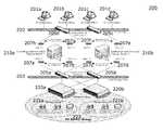
- the proposed approachmay run on a network 200 that may include, but is not limited to, a storage area network (SAN) 203 and a local area network (LAN) 202 , a wide area network (WAN), an iSCSI network, or another type of network.
- the network 200may be an internet protocol (IP) network, however, it is not so limited.
- IPinternet protocol
- the SAN network 203may be a SAN internal protocol (SAN IP) network, however, it is not so limited.
- the LAN 202may include components such as one or more clients 201 a , 201 b , 201 c , 201 d that communicate through one or more network switches 205 c , 205 d to one or more network interface cards (NICs) 207 e , 207 f , 207 g , 207 h to one or more servers 210 a , 210 b .
- the SAN 203may include, but is not limited to, an internet protocol (IP) SAN.
- IPinternet protocol
- the SAN 203may include components such as one or more servers 210 a , 210 b that communicate to one or more network switches 205 a , 205 b through a set of one or more network interface cards (NICs) 207 a , 207 b , 207 c , 207 d .
- Network switches 205 a , 205 b of the storage area network 203may communicate to Peer Storage (PS) series arrays 220 a , 220 b across the SAN 203 .
- PSPeer Storage
- the SAN 203may include components such as a PS series group 222 that may include, but is not limited, to, storage groups 221 a , 221 b and PS series data arrays 220 a , 220 b .
- the SAN 203may be considered to include the LAN 202 and the above-mentioned components with which the LAN 202 communicates, in addition to the above-mentioned components with which the SAN 203 communicates
- FIG. 3is a high level block diagram of an information handling system (IHS) 320 that is configured to verify connectivity in a storage area network according to the present invention.
- the IHS 320comprises a bus 325 .
- the bus 325is a connection between the various components of the IHS 320 .
- an input/output interface 321for connecting various input and output devices, such as a keyboard, mouse, display, speakers, etc. to the IHS 320 .
- a network interface 322for connecting the IHS 320 to the various networks that are known in the art.
- a Central Processing Unit (CPU) 323is connected to the bus 325 and provides for the execution of computer instructions.
- Memory 324provides volatile storage for data used for carrying out computer instructions.
- CPUCentral Processing Unit
- Disk storage 329provides non-volatile storage for software instructions such as the operating system (OS) 326 and the data 328 . Coupled with the OS 326 , is the file system 327 . Disk storage 329 may be any storage device known in the art.
- OSoperating system
- Disk storage 329may be any storage device known in the art.
- An embodiment of the IHS 320may comprise a data module 330 configured to communicate with one or more storage devices, through at least one of one or more host machines connected to one or more network switches.
- the IHSmay further comprise a computing module 331 that may activate, based on the communication, a test procedure at the one or more storage devices.
- the computing module 331may determine, through the test procedure, each state of connectivity from the one or more storage devices to each member computing device of a connectivity set.
- the connectivity setmay include: at least one other storage device, at least one of the one or more network switches, and at least one of the one or more host machines.
- the IHSmay further comprise a reporting module 332 (and/or display module) that may provide a report to one or more users, the report including each state of connectivity.
- the data module 330may be communicatively coupled with the computing module 331 .
- the data module 330may store and/or retrieve data as needed by other elements, including, but not limited to, the computing module 331 .
- the datamay be any data described herein.
- the data module 330may obtain data by running one or more connectivity tests on at least one member computing device of the storage area network.
- the data module 330may retrieve the data from any communicatively coupled source. For example, the data module 330 may retrieve data from the storage device 329 or via the input/output interface 321 or network interface 322 .
- the IHS 320may be implemented in various forms.
- the respective components and modules of the IHS 320may be combined in any manner that is known in the art and may be implemented in any combination of hardware and software.
- the above-described components and modulesmay be executable instructions in memory 324 or OS 326 operated on by CPU 323 .
- the IHS 320 and its various components and modulesmay be configured to operate in a manner corresponding to the above described method 100 , described herein above in relation to FIG. 1 and its various embodiments.
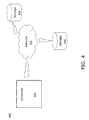
- FIG. 4illustrates another computer network environment 440 in which the present invention may be implemented.
- the computer 441 and the storage devices 443 and 444are linked through network 442 .
- the computer 441 and the storage devices 443 and 444may be connected through any network as is known in the art, including a storage area network (SAN), a wide area network (WAN) or local area network (LAN).
- the computer 441may embody the IHS 320 and/or any embodiment of the IHS described herein.
- the computer 441may be configured to carry out any method or embodiment thereof described herein.
- the computer 441is configured to verify connectivity of the network 442 and the storage devices 443 and 444 . While only two storage devices 443 and 444 are depicted, the computer network environment 440 may comprise any number of storage devices.
- the present inventionincludes a computer-implemented test procedure and/or test program that includes a script and suite of tools (implemented through Perl or another computer programming language) that may be run at time of installation that may verify and demonstrate that computing devices (storage devices, storage arrays, storage volumes, network switches, host machines, or other computing devices) are installed and configured correctly according to best practices.
- the scriptmay also create a report of the current computing device configuration, illustrating information related to each computing device, including, but not limited to, connectivity status information, computing information, port status information, bandwidth information, or configuration information.
- the computer-implemented test proceduremay include one or more tests for computing devices as follows.
- the scriptmay test that inter computing device Ethernet connections are configured and are working.
- the scriptmay test interfaces from a local Group to a Remote Group.
- the scriptmay test the connectivity between a host and the storage device and/or network switch.
- the scriptmay test the connectivity from a host to array members Ethernet ports: optionally, this test may require that a volume is created with an access control list (ACL) to it.
- ACLaccess control list
- the scriptmay test passive control by failing over to it and having it take over as the active controller.
- the scriptmay test whether timeout values on hosts are set to withstand a controller failover: optionally, this test may require that a host have a program like IOMETER running during control module (CM) failover tests.
- CMcontrol module
- FIG. 5illustrates operation of different testing stages (tests) within the test script.
- communication with one or more storage devicesis established, through one or more host machines connected to one or more network switches.
- testingis initiated 501 and one or more testing stages (also known as tests, test procedures, or test modules) are activated, including, but not limited to, an array interface status test 502 , a ping validation test 503 , a control module (CM) failover test 504 , and a replication test 505 .
- CMcontrol module
- Each of the test procedures 502 , 503 , 504 , 505may determine the state of connectivity from the one or more storage devices to at least one of: one or more storage device, one or more network switches, and one or more host machines (hosts). Although an order of tests is illustrated in FIG. 5 , the order of tests 502 , 503 , 504 , 505 is not limited, and different tests may be run in different orders, in parallel, or separately.
- the first test procedureis the array interface status test 502 . If the array interface status test 502 detects a failure, then the one or more users corrects one or more corresponding issues 506 and re-invokes the array interface status test 502 . If the array interface status test 502 passes, then the ping validation test 503 runs.
- the ping validation test 503detects a failure, then the one or more users corrects one or more corresponding issues 507 and re-invokes the ping validation test 503 . If the ping validation test 503 passes, then the CM failover test 504 runs. The CM failover test 504 induces a failover from the current CM to another CM. For example, the CM failover test may induce a failover from an active CM to a passive CM, or vice versa. If this failover results in a failure, including, but not limited to, a timeout of N seconds (where N may be 1, 6, 60, or another integer or real number value), then the issue is corrected 508 and the CM failover test is rerun 504 .
- Nmay be 1, 6, 60, or another integer or real number value
- the CM failover test 504After switching its CM successfully, for example, from active to passive, the CM failover test 504 then optionally re-invokes prior tests to test its current CM, such as, but not limited to, the array interface status test 502 and the ping validation test 503 .
- the CM failover test 504passes when failing over does not result in a failure that needs correction 508 and when the corresponding selected additional tests 502 , 503 are rerun and pass. If the CM failover test 504 passes, then the replication test 505 runs. If the replication test 505 detects a failure, then the one or more users corrects one or more corresponding issues 509 and re-invokes the replication test 505 .
- the replication testmay be run on either the active or the passive CM, or both.
- the test proceduremay exit 510 .
- the method 100 of the present inventionmay provide a user interface 600 .
- a user interface control interface 620is available with user controls 622 to enable the user to select tests individually, select tests in a sequence, open log file results, or exit the test program and/or test procedure.
- optional configuration commands 612may be accessed through a configuration interface 610 , including such configuration commands 612 as entering login information from a given computing device, starting one or more tests, running configuration scripts, logging out of a given computing device, or exiting the program.
- the method 100may provide a report 630 to one or more users, the report including each state of connectivity for each computing device which is tested by the one or more test procedures.
- a passing state of connectivity 632may be indicated by one or more Ethernet links (and/or ports and/or interfaces) being up
- a failing state of connectivity 633may be indicated by one or more Ethernet links (and/or ports and/or interfaces) being down.
- Each interface 610 , 620 , 630may also employ other display mechanisms, including, but not limited to, displaying group login information 611 , 621 , 631 , respectively.
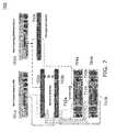
- a network 700may include hosts 701 a , 701 b , network switches 703 a , 703 b , 703 c and storage devices 704 a , 704 b , each storage device having one or more CMs, such as an active CMs 710 a , 710 b and a passive CMs 711 a , 711 b.
- a usermay login to the group lead storage device 704 a , from which tests are then initiated.
- a validation loginalso known as the login procedure, or SAN IP Validation Login
- the validation loginmay run from a host 701 b that has a connection into the SAN either through the network or through a dedicated management network.
- the login pathmay include a connection from the host 701 b to a management network switch 703 c , and a connection from the management switch 703 c to the group lead storage device 704 a .
- a group IP addressis provided in order to log in to the group lead 704 a .
- Each group(collectively 704 a , 704 b in the example of FIG. 7 , and optionally including one or more network switches 703 a , 703 b , 703 c and/or host machines 701 a , 701 b ) has a storage device that is known as the group lead ( 704 a in FIG. 7 ).
- a groupmay include one or more storage devices, it may also include network switches and/or hosts. Therefore, in the examples of FIG. 7 , it is understood that each group may include one or more storage devices 704 a , 704 b , but the group is not so limited, and the group may also include one or more network switches 703 a , 703 b , 703 c , and/or one or more hosts 701 a , 701 b .
- groups of two storage devices 704 a , 704 bare presented for conciseness of description, and it is understood that the group size is not so limited and may include network switches and/or hosts and/or other computing devices.
- each of the computing devicesmay include at least one active control module (CM) and/or passive CM.
- the storage devices 704 a , 704 bmay include active CMs ( 710 a , 710 b , respectively) and/or passive CMs ( 711 a , 711 b , respectively).
- the storage group(collectively 704 a and 704 b ) is configured.
- the storage devices 704 a , 704 b and the hosts 701 a , 701 b and their respective network interface cards (NICs)are configured and interconnected (through cabling, wiring, interfaces, ports, and/or any other interconnect means) to the network switches 703 a , 703 b , 703 c , as illustrated in FIG. 7 .
- the validation login proceduremay proceed.
- the validation login proceduremay include one or more of the following steps:
- testing commandsmay be initiated from the group lead storage device 704 a in order to test one or more member computing devices of the connectivity set (including, but not limited to, elements 701 a , 701 b , 703 a , 703 b , 703 c , 704 a , and 704 b ).
- testing commandsmay be initiated from the group lead storage device 704 a , in order to test computing devices which are directly connected to it, such as 703 a , 703 b , and 703 c .
- testing commandsmay be initiated from the group lead storage device 704 a , in order to test computing devices which are indirectly connected to it, such as 701 a , 701 b , and 704 b.
- a key advantage of the present inventionis that tests may be initiated and/or run directly from the group lead 704 a , as opposed to being initiated and/or run from the host 701 b .
- one testing pathmay start from group lead 704 a and then test network switch 703 b , and then test storage device 704 b .
- Another testing pathmay start from group lead 704 a and then test network switch 703 a , and then test storage device 704 b .
- Yet another testing pathmay start from group lead 704 a , and test management switch 703 c , host 701 b , network switch 703 a , and host 701 a .
- a testing pathstarts from the group lead 704 a , the present invention is not so limited.
- the present inventionmay be configured to test the interconnect in the storage area network, including the interconnect between the member computing devices.
- an interface status test(array status test 502 of FIG. 5 ) may be performed.
- the interface status testvalidates that interfaces on the active controller module (CM) 710 a are connected to a switch and one or more links are present. This procedure is repeated until the interfaces are tested for the member computing devices (which may include, but are not limited to, the member computing devices 701 a , 701 b , 703 a , 703 b , 703 c , 704 a , 704 b , in the example of FIG. 7 ).
- the member computing deviceswhich may include, but are not limited to, the member computing devices 701 a , 701 b , 703 a , 703 b , 703 c , 704 a , 704 b , in the example of FIG. 7 ).
- the interface status test(also known as the interfaces status test) may include one or more of the following steps, in order to test one or more interfaces:
- a ping test(ping validation test 503 of FIG. 5 ) may be performed.
- the ping testmay run an internet control message protocol (ICMP) ping test from interfaces on the group lead 704 a to the interfaces on the other member computing devices (including, but not limited to, 704 b , and optionally also including 703 a , 703 b , 703 c , 701 a , and 701 b ) within a group.
- the testwill start on the group lead interface (for example, Ethernet eth0 interface) and when interfaces on the other member computing devices are validated successfully (ICMP ping test passed) then the test switches to another group lead interface (for example, Ethernet eth1 interface) reruns the test. This procedure is repeated until the interfaces on the group lead 704 a are tested and the group lead 704 a tests the interfaces on selected computing devices.
- ICMPinternet control message protocol
- the ping test(also known as the ping validation test or SAN IP validation ping test) may include one or more of the following steps:
- the ping testmay include an interface to host initiator ping test (also known as the interface to initiator test).
- the interface to initiator testmay run an ICMP ping test from one or more interfaces on the group lead 704 a to one or more interfaces on a host 701 b with an IP Access Control List (ACL) entry on a test volume (a test volume may include one or more storage devices 704 a , 704 b ).
- ACLIP Access Control List
- the testmay start on the Group Lead eth0 Ethernet interface and when Network Interface Cards (NICs) on the Host 701 b are validated (pass an ICMP ping test) then the test may switch to the Group Lead eth1 Ethernet interface and rerun the test. This procedure may be repeated until the interfaces in the group (associated with the member computing devices of the group) are tested.
- NICsNetwork Interface Cards
- the interface to host initiator testmay include one or more of the following steps:
- CM failover test 504 of FIG. 5may be performed.
- the CM failovermay disable the active CM and enable the passive CM by making it active. Then, the previous tests are rerun and validate the now new active CM.
- the CM failover testmay include one or more of the following steps:
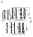
- a network 800may include a production site (production group), or local group 706 , that includes member computing devices such as hosts 701 a , 701 b , network switches 703 a , 703 b , 703 c and storage devices 704 a , 704 b , each storage device having one or more CMs, such as an active CM and a passive CM.
- the network 800may also include a data replication (DR) site (DR group), or remote group 705 , that includes member computing devices such as network switches 703 d , 703 e , and storage devices 704 c , 704 d.
- DRdata replication
- a replication test(replication test 505 of FIG. 5 ) may be performed.
- the replication testmay run an ICMP ping test from interfaces on the production group 706 to the interfaces on the DR group 705 .
- the replication testmay start on the production group lead 704 a Ethernet (eth0) interface and when interfaces on the DR group are validated (pass an ICMP ping test) then the test may switch to the next Ethernet (eth1) interface on the group lead 704 a and rerun the test. This may be repeated for the interfaces on the production group lead 704 a , until the interfaces on the DR group 705 and its associated member computing devices are tested.
- the group lead 704 amay test all interfaces associated with network switches 703 d , 703 e , and storage devices 704 c , 704 d , and other member computing devices.
- the CM failovermay be performed, and the replication test may be repeated.
- the replication testmay run an ICMP ping test from interfaces on the DR group to the interfaces on the production group.
- the group lead 704 cmay test interfaces associated with network switches 703 a , 703 b , and storage devices 704 a , 704 b.
- the replication testmay include one or more of the following steps:
- additional embodiments of the user interface 600may include other features, including, but not limited to, the following steps. Note, the order of the steps to follow is not limited, and in alternative embodiments other steps may be performed:
- An advantage of the present inventionis that it simplifies the complex process of validating the customer's SAN environment. By validating an environment before putting the customer system in production, efficiency is achieved. Detecting issues in a customer's environment prior to, or at, the time of deployment, helps to reduce the occurrence of commonly encountered issues, and may reduce the number of phone calls received into technical support.
- testsmay be initiated and/or run directly from a group lead storage device, as opposed to being initiated and/or run from a host computing device.
- the various methods and machines described hereinmay be implemented by a physical, virtual or hybrid general-purpose computer, or a computer network environment such as the computer network environment 440 .
- a general purpose computermay be transformed into the machines that execute the methods described above, for example, by loading software instructions into memory or nonvolatile storage for execution by a central processing unit.
- Embodiments or aspects thereofmay be implemented in the form of hardware, firmware, or software or any combination thereof. If implemented in software, the software may be stored on any non-transient computer readable medium that is configured to enable a processor to load the software or subsets of instructions thereof. The processor then executes the instructions and is configured to operate or cause an apparatus to operate in a manner as described herein.
- firmware, software, routines, or instructionsmay be described herein as performing certain actions and/or functions of data processors. However, it should be appreciated that such descriptions contained herein are merely for convenience and that such actions in fact result from computing devices, processors, controllers, or other devices executing the firmware, software, routines, instructions, etc.
Landscapes
- Engineering & Computer Science (AREA)
- Theoretical Computer Science (AREA)
- Signal Processing (AREA)
- Computer Networks & Wireless Communication (AREA)
- General Engineering & Computer Science (AREA)
- General Physics & Mathematics (AREA)
- Physics & Mathematics (AREA)
- Human Computer Interaction (AREA)
- Health & Medical Sciences (AREA)
- Cardiology (AREA)
- General Health & Medical Sciences (AREA)
- Environmental & Geological Engineering (AREA)
- Debugging And Monitoring (AREA)
Abstract
Description
- 1. A SAN IP Validation utility is installed on a
host 701b(including, but not limited to, a WINDOWS host). - 2. A SAN IP
Validation Windows Host 701baccesses an iSCSI well known address (WKA) network (throughnetwork switch 703a) or the Storage Groups Network Management network (throughmanagement switch 703c). - 3. The SAN IP Validation utility logs into a Group IP (Group Lead member) or Network Management Group IP (if in use).
- 4. Storage device command line interface (CLI) commands are run from a Group Lead member (such as704b) to all other Members in the Storage Group (such as704a).
- 5. Commands and/or results are captured and saved in one or more log files on the SAN
IP Validation Host 701b.
- 1. A SAN IP Validation utility is installed on a
- 1. Select Interface Status Test.
- 2.
Group lead member 704ainitiates CLI commands to other members in the Group (including but not limited tostorage device 704b) to perform a show interface status on their active CMs (710a,710b). - 3. Commands and/or results are captured and saved in one or more log files on a
host 701b.
- 1. Select the ping test.
- 2. The
group lead member 704ainitiates CLI commands to gather interface and/or IP information. - 3. The group lead pings from its Ethernet port (for example, eth0 port) to other ports (for example, eth0 and/or eth1) of the other member computing devices on the
active CM 710a. - 4. The group lead then pings from its Eth1 port to other member computing devices (including, but not limited to,704b, and optionally also including703a,703b,703c,701a, and701b) Ethernet ports (such as eth0 and/or eth1 ports).
- 5. The commands and/or results are captured and saved in one or more log files on the
host 701b.
- 1. Select the ping test.
- 2. A user is prompted to enter a test volume that is configured with the proper IP ACL for the
host 701bto test. - 3. Verification of the test volume configuration is performed.
- 4. A group lead member initiates CLI commands to gather interface and/or IP information for member interfaces.
- 5. A ping test is run from interfaces on the group to interfaces on the Host.
- 6. Commands and/or results are captured and saved in one or more log files on the host.
- 1. Select the CM failover test.
- 2. Prompt the user to verify that the user wants to failover the CMs.
- 3. After the user verification, failover each member computing device's CMs one at a time verifying that the previous member computing device is up (performing as expected) before moving to the next member computing device.
- 4. Commands and/or results are captured and saved in one or more log files on the host.
- 1. Select the replication test.
- 2. Log the user into the replication group, if not already logged in.
- 3.
Group lead members production group 706 andDR group 705, respectively, initiate CLI commands to gather interface and/or IP information. - 4.
Group lead 704aon theproduction group 706 runs a ping test from its Ethernet (Eth0) port to theDR group 705 interfaces on the active CMs. - 5.
Group lead 704aon theproduction group 706 runs a ping test from its other Ethernet ports (including, but not limited to, Eth1) to theDR group 705 interfaces on the active CMs. - 6. This procedure is repeated until active interfaces on the
production group 706 complete ping tests to interfaces on theDR group 705 active interfaces. - 7. Commands and/or results are captured and saved in one or more log files on the
host 701b.
- 1) The user may be prompted to enter login information for the group of member computing devices by selecting a menu option.
- a. The user may indicate whether the network is a dedicated management network.
- b. The user interface may prompt the user for the group IP address or the management network address and the group administration (grpadmin) password. The script uses the grpadmin account to access one or more of the storage devices.
- c. The user interface may prompt the user to test to a replication partner group (and/or replication partner array) and/or password.
- 2) Once logged in, the group logged into may be highlighted in the currently logged into group field. Highlighting and indicators herein may include changes in color of text, text, graphics, video and/or audio presentation. Replication partners may also be highlighted.
- 3) The user may select the SAN Validation Test.
- 4) The user may select the Array Interface Status Test. Running the Array Interface Status Test provides a quick status of member interfaces, including, but not limited to, speed and link state. Interfaces that fail are highlighted.
- 5) After running the Array Interface Status Test and verifying that the ports are configured for the proper speed and link up state, the user may run the ping validation test. The ping validation test in a single member configuration may run a ping test from the storage device to one or more storage devices (a pre-configured volume) logged into a host. In a multi-member group the ping validation test may run a ping test from each interface on the group lead to the other member interfaces.
- i) The ping validation test may run on a single member. The first screen in the ping validation test on a single member may inform the user that it found a single member and that the test may run to a test volume.
- 6) The user may be prompted to verify that a test volume is configured and that there is an active ACL setup for the volume.
- 7) If a test volume is setup, the program finds available volumes and lists them for the user.
- 8) The user may select a preferred volume for the test.
- 9) The program finds the ACLs associated with the selected volume and runs a ping test from the storage device (array) interfaces back to each ACL that it found. Failed tests are highlighted using an indicator (or color) and are investigated as to why the connection failed.
- i) The ping validation test includes a multiple member information user display screen informing the user to run a ping test from the group lead interfaces out to the member interfaces.
- 10) The test runs from the group lead out to members. If the management port is configured on the storage devices (storage arrays), then the display informs the user that the storage devices are setup. Errors are indicated using highlighting and are fixed before continuing to the CM failover test.
- 11) The user may choose to run a ping test from a host to group member interfaces.
- 12) Available volumes are detected and listed. The user may select a volume to test.
- 13) The user may confirm whether the correct volume is listed.
- 14) Once the ping validation test passes, the user may select the CM failover test. The CM failover test may fail the active controllers over to the passive controllers.
- 15) An informational screen is displayed that explains that the test fails over each members CM.
- 16) The display indicates the current active CM and fails it over to the passive CM.
- 17) Because the storage device (array) is running on a new controller (the passive controller is now in use, as opposed to the active controller being in use) the user is prompted to rerun the storage device (array) interface status and the ping validation tests in order to verify that the controllers and interfaces are operating properly.
- 18) If a replication partner is configured during the initial login, then a user may select replication partner tests.
- 19) Upon selecting the replication partner test, a ping test is run from each of the local array's interfaces to the interfaces on the remote replication partner.
- 20) The user may view the log file that is created by selecting a menu option.
- 21) Once the tests are complete, the user may select the group configuration script. This script provides the user with a point in time snapshot of the current configuration of the group. If MICROSOFT EXCEL is installed on the host that the user is running the program from, then the program outputs the results into a MICROSOFT EXCEL spreadsheet. Alternatively, if MICROSOFT EXCEL is not installed, then the program provides the user with a text output file.
- 22) The program asks the user for user information. This information is included in the generated MICROSOFT EXCEL file and/or text file.
- 23) When the program completes, it provides the name and location of an output file.
- 1) The user may be prompted to enter login information for the group of member computing devices by selecting a menu option.
Claims (20)
Priority Applications (1)
| Application Number | Priority Date | Filing Date | Title |
|---|---|---|---|
| US14/228,608US9436411B2 (en) | 2014-03-28 | 2014-03-28 | SAN IP validation tool |
Applications Claiming Priority (1)
| Application Number | Priority Date | Filing Date | Title |
|---|---|---|---|
| US14/228,608US9436411B2 (en) | 2014-03-28 | 2014-03-28 | SAN IP validation tool |
Publications (2)
| Publication Number | Publication Date |
|---|---|
| US20150277804A1 US20150277804A1 (en) | 2015-10-01 |
| US9436411B2true US9436411B2 (en) | 2016-09-06 |
Family
ID=54190413
Family Applications (1)
| Application Number | Title | Priority Date | Filing Date |
|---|---|---|---|
| US14/228,608ActiveUS9436411B2 (en) | 2014-03-28 | 2014-03-28 | SAN IP validation tool |
Country Status (1)
| Country | Link |
|---|---|
| US (1) | US9436411B2 (en) |
Cited By (2)
| Publication number | Priority date | Publication date | Assignee | Title |
|---|---|---|---|---|
| US9720758B2 (en) | 2013-09-11 | 2017-08-01 | Dell Products, Lp | Diagnostic analysis tool for disk storage engineering and technical support |
| US10223230B2 (en) | 2013-09-11 | 2019-03-05 | Dell Products, Lp | Method and system for predicting storage device failures |
Families Citing this family (18)
| Publication number | Priority date | Publication date | Assignee | Title |
|---|---|---|---|---|
| US9454423B2 (en) | 2013-09-11 | 2016-09-27 | Dell Products, Lp | SAN performance analysis tool |
| US9317349B2 (en) | 2013-09-11 | 2016-04-19 | Dell Products, Lp | SAN vulnerability assessment tool |
| US9763518B2 (en) | 2014-08-29 | 2017-09-19 | Cisco Technology, Inc. | Systems and methods for damping a storage system |
| US9853873B2 (en)* | 2015-01-10 | 2017-12-26 | Cisco Technology, Inc. | Diagnosis and throughput measurement of fibre channel ports in a storage area network environment |
| US10484244B2 (en)* | 2015-01-20 | 2019-11-19 | Dell Products, Lp | Validation process for a storage array network |
| US9900250B2 (en) | 2015-03-26 | 2018-02-20 | Cisco Technology, Inc. | Scalable handling of BGP route information in VXLAN with EVPN control plane |
| US10222986B2 (en) | 2015-05-15 | 2019-03-05 | Cisco Technology, Inc. | Tenant-level sharding of disks with tenant-specific storage modules to enable policies per tenant in a distributed storage system |
| US11588783B2 (en) | 2015-06-10 | 2023-02-21 | Cisco Technology, Inc. | Techniques for implementing IPV6-based distributed storage space |
| US9892075B2 (en) | 2015-12-10 | 2018-02-13 | Cisco Technology, Inc. | Policy driven storage in a microserver computing environment |
| US20170351639A1 (en) | 2016-06-06 | 2017-12-07 | Cisco Technology, Inc. | Remote memory access using memory mapped addressing among multiple compute nodes |
| US11563695B2 (en) | 2016-08-29 | 2023-01-24 | Cisco Technology, Inc. | Queue protection using a shared global memory reserve |
| US10545914B2 (en) | 2017-01-17 | 2020-01-28 | Cisco Technology, Inc. | Distributed object storage |
| US10243823B1 (en) | 2017-02-24 | 2019-03-26 | Cisco Technology, Inc. | Techniques for using frame deep loopback capabilities for extended link diagnostics in fibre channel storage area networks |
| US10713203B2 (en) | 2017-02-28 | 2020-07-14 | Cisco Technology, Inc. | Dynamic partition of PCIe disk arrays based on software configuration / policy distribution |
| US10254991B2 (en) | 2017-03-06 | 2019-04-09 | Cisco Technology, Inc. | Storage area network based extended I/O metrics computation for deep insight into application performance |
| US10303534B2 (en) | 2017-07-20 | 2019-05-28 | Cisco Technology, Inc. | System and method for self-healing of application centric infrastructure fabric memory |
| US10404596B2 (en) | 2017-10-03 | 2019-09-03 | Cisco Technology, Inc. | Dynamic route profile storage in a hardware trie routing table |
| US10942666B2 (en) | 2017-10-13 | 2021-03-09 | Cisco Technology, Inc. | Using network device replication in distributed storage clusters |
Citations (77)
| Publication number | Priority date | Publication date | Assignee | Title |
|---|---|---|---|---|
| US5084819A (en) | 1988-11-10 | 1992-01-28 | Response Technologies Inc. | Data collection, analysis, and response system and method |
| US5917724A (en) | 1997-12-20 | 1999-06-29 | Ncr Corporation | Method for predicting disk drive failure by monitoring the rate of growth of defects within a disk drive |
| US6148335A (en) | 1997-11-25 | 2000-11-14 | International Business Machines Corporation | Performance/capacity management framework over many servers |
| US6189084B1 (en) | 1997-07-14 | 2001-02-13 | Horiba, Ltd. | Debugging method and monitoring method for analysis instruments |
| US6408406B1 (en) | 1999-08-31 | 2002-06-18 | Western Digital Technologies, Inc. | Hard disk drive infant mortality test |
| US6415189B1 (en) | 1999-07-23 | 2002-07-02 | International Business Machines Corporation | Method and system for predicting disk drive failures |
| US20020087950A1 (en) | 2000-09-27 | 2002-07-04 | International Business Machines Corporation | Capturing snapshots of a debuggee's state during a debug session |
| US6434714B1 (en) | 1999-02-04 | 2002-08-13 | Sun Microsystems, Inc. | Methods, systems, and articles of manufacture for analyzing performance of application programs |
| US6467054B1 (en) | 1995-03-13 | 2002-10-15 | Compaq Computer Corporation | Self test for storage device |
| US20030112538A1 (en) | 2001-12-18 | 2003-06-19 | International Business Machines Corporation; | Adaptive event-based predictive failure analysis measurements in a hard disk drive |
| US20040205403A1 (en) | 2003-03-28 | 2004-10-14 | Mitchell Markow | Acoustic power spectra sensor for hard disk drive to provide early detection of drive failure and diagnostic capabilities |
| US20040260967A1 (en) | 2003-06-05 | 2004-12-23 | Copan Systems, Inc. | Method and apparatus for efficient fault-tolerant disk drive replacement in raid storage systems |
| US6845306B2 (en) | 2000-11-09 | 2005-01-18 | Honeywell International Inc. | System and method for performance monitoring of operational equipment used with machines |
| US20050265160A1 (en) | 2004-05-27 | 2005-12-01 | Mitsubishi Denki Kabushiki Kaisha | Disk information display device |
| US20060047715A1 (en) | 2004-08-27 | 2006-03-02 | Archer Analytics, Inc. | System and method for managing and analyzing data from an operational database |
| US20060053338A1 (en) | 2004-09-08 | 2006-03-09 | Copan Systems, Inc. | Method and system for disk drive exercise and maintenance of high-availability storage systems |
| US20060112135A1 (en) | 2004-11-23 | 2006-05-25 | Dba Infopower, Inc. | Real-time database performance and availability change root cause analysis method and system |
| US7136768B1 (en) | 2005-03-31 | 2006-11-14 | Network Appliance, Inc. | Method and system for reliability analysis of disk drive failures |
| US20070136389A1 (en) | 2005-11-29 | 2007-06-14 | Milena Bergant | Replication of a consistency group of data storage objects from servers in a data network |
| US7278057B2 (en) | 2003-07-31 | 2007-10-02 | International Business Machines Corporation | Automated hang detection in Java thread dumps |
| US7302617B2 (en) | 2003-05-12 | 2007-11-27 | Sun Microsystems, Inc. | Managing and predicting risk for computer devices using exposure management techniques |
| US20070272751A1 (en) | 2006-05-24 | 2007-11-29 | Fujitsu Limited | Storage device having self-diagnosis function, control device that controls self-diagnosis function in storage device, and method of performing self-diagnosis on storage device |
| US20080059292A1 (en) | 2006-08-29 | 2008-03-06 | Myers Lloyd N | Systems and methods related to continuous performance improvement |
| US20080301394A1 (en)* | 2007-05-29 | 2008-12-04 | Muppirala Kishore Kumar | Method And A System To Determine Device Criticality During SAN Reconfigurations |
| US7490073B1 (en) | 2004-12-21 | 2009-02-10 | Zenprise, Inc. | Systems and methods for encoding knowledge for automated management of software application deployments |
| US7539907B1 (en) | 2006-05-05 | 2009-05-26 | Sun Microsystems, Inc. | Method and apparatus for determining a predicted failure rate |
| US20090161243A1 (en) | 2007-12-21 | 2009-06-25 | Ratnesh Sharma | Monitoring Disk Drives To Predict Failure |
| US7603395B1 (en) | 2006-05-02 | 2009-10-13 | Emc Corporation | Using pseudosnapshots for continuous data protection systems to surface a copy of data |
| US20090259749A1 (en) | 2006-02-22 | 2009-10-15 | Emulex Design & Manufacturing Corporation | Computer system input/output management |
| US7606986B1 (en)* | 2004-08-30 | 2009-10-20 | Symantec Operating Corporation | System and method for resolving SAN fabric partitions |
| US20100023867A1 (en) | 2008-01-29 | 2010-01-28 | Virtual Instruments Corporation | Systems and methods for filtering network diagnostic statistics |
| US20100030586A1 (en) | 2008-07-31 | 2010-02-04 | Choicepoint Services, Inc | Systems & methods of calculating and presenting automobile driving risks |
| US20100050023A1 (en) | 2005-07-29 | 2010-02-25 | Bmc Software, Inc. | System, method and computer program product for optimized root cause analysis |
| US7676445B2 (en) | 2003-08-20 | 2010-03-09 | International Business Machines Corporation | Apparatus, system and method for developing failure prediction software |
| US7765190B1 (en) | 2006-05-02 | 2010-07-27 | Emc Corporation | Pseudosnapshot creation and implementation using continuous data protection |
| US20100324945A1 (en) | 2009-05-12 | 2010-12-23 | Ronald Paul Hessing | Data insurance system based on dynamic risk management |
| US7860015B1 (en)* | 2006-12-18 | 2010-12-28 | Emc Corporation | Methods and apparatus for physical and logical SAN fabric analysis |
| US7865278B2 (en) | 2006-06-14 | 2011-01-04 | Spx Corporation | Diagnostic test sequence optimization method and apparatus |
| US7877645B2 (en) | 2007-07-30 | 2011-01-25 | Hewlett-Packard Development Company, L.P. | Use of operational configuration parameters to predict system failures |
| US20110106763A1 (en) | 2009-10-30 | 2011-05-05 | Symantec Corporation | Storage replication systems and methods |
| US8005709B2 (en) | 2003-06-17 | 2011-08-23 | Oracle International Corporation | Continuous audit process control objectives |
| US20110276836A1 (en) | 2008-10-16 | 2011-11-10 | Chen Kahana | Performance analysis of applications |
| US8065571B2 (en)* | 2008-10-14 | 2011-11-22 | International Business Machines Corporation | Storage area network (SAN) link integrity tester |
| US8073821B2 (en) | 2000-08-17 | 2011-12-06 | Emc Corporation | Method and apparatus for managing and archiving performance information relating to storage system |
| US8103463B2 (en) | 2006-09-21 | 2012-01-24 | Impact Technologies, Llc | Systems and methods for predicting failure of electronic systems and assessing level of degradation and remaining useful life |
| US8136124B2 (en) | 2007-01-18 | 2012-03-13 | Oracle America, Inc. | Method and apparatus for synthesizing hardware counters from performance sampling |
| US20120066030A1 (en) | 2010-09-09 | 2012-03-15 | Limpert Bruce R | Performance Management System And Dashboard |
| US20120136985A1 (en) | 2010-11-29 | 2012-05-31 | Ana-Maria Popescu | Detecting controversial events |
| US20120179936A1 (en) | 2011-01-07 | 2012-07-12 | International Business Machines Corporation | Early collection of diagnostic information |
| US8315991B2 (en) | 2010-04-20 | 2012-11-20 | International Business Machines Corporation | Detecting inadvertent or malicious data corruption in storage subsystems and recovering data |
| US20130091499A1 (en) | 2011-10-10 | 2013-04-11 | Vmware, Inc. | Method and apparatus for comparing configuration and topology of virtualized datacenter inventories |
| US8521546B2 (en) | 1998-09-25 | 2013-08-27 | Health Hero Network | Dynamic modeling and scoring risk assessment |
| US8631115B2 (en)* | 2006-10-16 | 2014-01-14 | Cisco Technology, Inc. | Connectivity outage detection: network/IP SLA probes reporting business impact information |
| US20140040897A1 (en) | 2012-08-04 | 2014-02-06 | Microsoft Corporation | Function Evaluation using Lightweight Process Snapshots |
| US20140108855A1 (en) | 2012-10-17 | 2014-04-17 | Lsi Corporation | Heuristic Approach for Faster Consistency Check in a Redundant Storage System |
| US8760780B1 (en) | 2012-03-22 | 2014-06-24 | Amazon Technologies, Inc. | System and method for disk sector failure prediction |
| US8812342B2 (en) | 2010-06-15 | 2014-08-19 | International Business Machines Corporation | Managing and monitoring continuous improvement in detection of compliance violations |
| US20140244362A1 (en) | 2013-02-27 | 2014-08-28 | Tata Consultancy Services Limited | System and method to provide predictive analysis towards performance of target objects associated with organization |
| US20140244343A1 (en) | 2013-02-22 | 2014-08-28 | Bank Of America Corporation | Metric management tool for determining organizational health |
| US20140278730A1 (en) | 2013-03-14 | 2014-09-18 | Memorial Healthcare System | Vendor management system and method for vendor risk profile and risk relationship generation |
| US8856927B1 (en) | 2003-07-22 | 2014-10-07 | Acronis International Gmbh | System and method for using snapshots for rootkit detection |
| US20140310714A1 (en) | 2013-04-11 | 2014-10-16 | Oracle International Corporation | Predictive diagnosis of sla violations in cloud services by seasonal trending and forecasting with thread intensity analytics |
| US20140358357A1 (en) | 2013-06-03 | 2014-12-04 | Honda Motor Co., Ltd. | Diagnostic assistance |
| US8909990B2 (en) | 2012-08-04 | 2014-12-09 | Microsoft Corporation | Historical software diagnostics using lightweight process snapshots |
| US20150046756A1 (en) | 2013-08-08 | 2015-02-12 | Lsi Corporation | Predictive failure analysis to trigger rebuild of a drive in a raid array |
| US20150052406A1 (en) | 2013-08-19 | 2015-02-19 | Concurix Corporation | Combined Performance Tracer and Snapshot Debugging System |
| US20150067153A1 (en) | 2013-08-28 | 2015-03-05 | Kentucky State University | Remote monitoring of data facility in real-time using wireless sensor network |
| US20150074467A1 (en) | 2013-09-11 | 2015-03-12 | Dell Products, Lp | Method and System for Predicting Storage Device Failures |
| US20150074462A1 (en) | 2013-09-11 | 2015-03-12 | Dell Products, Lp | Diagnostic analysis tool for disk storage engineering and technical support |
| US20150074463A1 (en) | 2013-09-11 | 2015-03-12 | Dell Products, Lp | SAN Performance Analysis Tool |
| US20150074452A1 (en) | 2013-09-09 | 2015-03-12 | Fujitsu Limited | Storage control device and method for controlling storage devices |
| US20150074468A1 (en) | 2013-09-11 | 2015-03-12 | Dell Produts, LP | SAN Vulnerability Assessment Tool |
| US20150074055A1 (en) | 2013-09-11 | 2015-03-12 | Dell Products, Lp | Auto-Snapshot Manager Analysis Tool |
| US20150135033A1 (en) | 2013-11-08 | 2015-05-14 | Sandisk Enterprise Ip Llc | Method and system for improving error correction in data storage |
| US9084937B2 (en) | 2008-11-18 | 2015-07-21 | Gtech Canada Ulc | Faults and performance issue prediction |
| US9189309B1 (en) | 2013-09-25 | 2015-11-17 | Emc Corporation | System and method for predicting single-disk failures |
| US20160039291A1 (en) | 2014-08-07 | 2016-02-11 | At&T Intellectual Property I, L.P. | Vehicle Battery Data Analysis Service |
Family Cites Families (1)
| Publication number | Priority date | Publication date | Assignee | Title |
|---|---|---|---|---|
| US8515015B2 (en)* | 2008-05-09 | 2013-08-20 | Verizon Patent And Licensing Inc. | Method and system for test automation and dynamic test environment configuration |
- 2014
- 2014-03-28USUS14/228,608patent/US9436411B2/enactiveActive
Patent Citations (78)
| Publication number | Priority date | Publication date | Assignee | Title |
|---|---|---|---|---|
| US5084819A (en) | 1988-11-10 | 1992-01-28 | Response Technologies Inc. | Data collection, analysis, and response system and method |
| US6467054B1 (en) | 1995-03-13 | 2002-10-15 | Compaq Computer Corporation | Self test for storage device |
| US6189084B1 (en) | 1997-07-14 | 2001-02-13 | Horiba, Ltd. | Debugging method and monitoring method for analysis instruments |
| US6148335A (en) | 1997-11-25 | 2000-11-14 | International Business Machines Corporation | Performance/capacity management framework over many servers |
| US5917724A (en) | 1997-12-20 | 1999-06-29 | Ncr Corporation | Method for predicting disk drive failure by monitoring the rate of growth of defects within a disk drive |
| US8521546B2 (en) | 1998-09-25 | 2013-08-27 | Health Hero Network | Dynamic modeling and scoring risk assessment |
| US6434714B1 (en) | 1999-02-04 | 2002-08-13 | Sun Microsystems, Inc. | Methods, systems, and articles of manufacture for analyzing performance of application programs |
| US6415189B1 (en) | 1999-07-23 | 2002-07-02 | International Business Machines Corporation | Method and system for predicting disk drive failures |
| US6408406B1 (en) | 1999-08-31 | 2002-06-18 | Western Digital Technologies, Inc. | Hard disk drive infant mortality test |
| US8073821B2 (en) | 2000-08-17 | 2011-12-06 | Emc Corporation | Method and apparatus for managing and archiving performance information relating to storage system |
| US20020087950A1 (en) | 2000-09-27 | 2002-07-04 | International Business Machines Corporation | Capturing snapshots of a debuggee's state during a debug session |
| US6845306B2 (en) | 2000-11-09 | 2005-01-18 | Honeywell International Inc. | System and method for performance monitoring of operational equipment used with machines |
| US20030112538A1 (en) | 2001-12-18 | 2003-06-19 | International Business Machines Corporation; | Adaptive event-based predictive failure analysis measurements in a hard disk drive |
| US20040205403A1 (en) | 2003-03-28 | 2004-10-14 | Mitchell Markow | Acoustic power spectra sensor for hard disk drive to provide early detection of drive failure and diagnostic capabilities |
| US7302617B2 (en) | 2003-05-12 | 2007-11-27 | Sun Microsystems, Inc. | Managing and predicting risk for computer devices using exposure management techniques |
| US20040260967A1 (en) | 2003-06-05 | 2004-12-23 | Copan Systems, Inc. | Method and apparatus for efficient fault-tolerant disk drive replacement in raid storage systems |
| US8005709B2 (en) | 2003-06-17 | 2011-08-23 | Oracle International Corporation | Continuous audit process control objectives |
| US8856927B1 (en) | 2003-07-22 | 2014-10-07 | Acronis International Gmbh | System and method for using snapshots for rootkit detection |
| US7278057B2 (en) | 2003-07-31 | 2007-10-02 | International Business Machines Corporation | Automated hang detection in Java thread dumps |
| US7676445B2 (en) | 2003-08-20 | 2010-03-09 | International Business Machines Corporation | Apparatus, system and method for developing failure prediction software |
| US20050265160A1 (en) | 2004-05-27 | 2005-12-01 | Mitsubishi Denki Kabushiki Kaisha | Disk information display device |
| US20060047715A1 (en) | 2004-08-27 | 2006-03-02 | Archer Analytics, Inc. | System and method for managing and analyzing data from an operational database |
| US7606986B1 (en)* | 2004-08-30 | 2009-10-20 | Symantec Operating Corporation | System and method for resolving SAN fabric partitions |
| US20060053338A1 (en) | 2004-09-08 | 2006-03-09 | Copan Systems, Inc. | Method and system for disk drive exercise and maintenance of high-availability storage systems |
| US20060112135A1 (en) | 2004-11-23 | 2006-05-25 | Dba Infopower, Inc. | Real-time database performance and availability change root cause analysis method and system |
| US7490073B1 (en) | 2004-12-21 | 2009-02-10 | Zenprise, Inc. | Systems and methods for encoding knowledge for automated management of software application deployments |
| US7136768B1 (en) | 2005-03-31 | 2006-11-14 | Network Appliance, Inc. | Method and system for reliability analysis of disk drive failures |
| US20100050023A1 (en) | 2005-07-29 | 2010-02-25 | Bmc Software, Inc. | System, method and computer program product for optimized root cause analysis |
| US20070136389A1 (en) | 2005-11-29 | 2007-06-14 | Milena Bergant | Replication of a consistency group of data storage objects from servers in a data network |
| US20090259749A1 (en) | 2006-02-22 | 2009-10-15 | Emulex Design & Manufacturing Corporation | Computer system input/output management |
| US7603395B1 (en) | 2006-05-02 | 2009-10-13 | Emc Corporation | Using pseudosnapshots for continuous data protection systems to surface a copy of data |
| US7765190B1 (en) | 2006-05-02 | 2010-07-27 | Emc Corporation | Pseudosnapshot creation and implementation using continuous data protection |
| US7539907B1 (en) | 2006-05-05 | 2009-05-26 | Sun Microsystems, Inc. | Method and apparatus for determining a predicted failure rate |
| US20070272751A1 (en) | 2006-05-24 | 2007-11-29 | Fujitsu Limited | Storage device having self-diagnosis function, control device that controls self-diagnosis function in storage device, and method of performing self-diagnosis on storage device |
| US7865278B2 (en) | 2006-06-14 | 2011-01-04 | Spx Corporation | Diagnostic test sequence optimization method and apparatus |
| US20080059292A1 (en) | 2006-08-29 | 2008-03-06 | Myers Lloyd N | Systems and methods related to continuous performance improvement |
| US8103463B2 (en) | 2006-09-21 | 2012-01-24 | Impact Technologies, Llc | Systems and methods for predicting failure of electronic systems and assessing level of degradation and remaining useful life |
| US8631115B2 (en)* | 2006-10-16 | 2014-01-14 | Cisco Technology, Inc. | Connectivity outage detection: network/IP SLA probes reporting business impact information |
| US7860015B1 (en)* | 2006-12-18 | 2010-12-28 | Emc Corporation | Methods and apparatus for physical and logical SAN fabric analysis |
| US8136124B2 (en) | 2007-01-18 | 2012-03-13 | Oracle America, Inc. | Method and apparatus for synthesizing hardware counters from performance sampling |
| US20080301394A1 (en)* | 2007-05-29 | 2008-12-04 | Muppirala Kishore Kumar | Method And A System To Determine Device Criticality During SAN Reconfigurations |
| US7877645B2 (en) | 2007-07-30 | 2011-01-25 | Hewlett-Packard Development Company, L.P. | Use of operational configuration parameters to predict system failures |
| US20090161243A1 (en) | 2007-12-21 | 2009-06-25 | Ratnesh Sharma | Monitoring Disk Drives To Predict Failure |
| US20100023867A1 (en) | 2008-01-29 | 2010-01-28 | Virtual Instruments Corporation | Systems and methods for filtering network diagnostic statistics |
| US20100030586A1 (en) | 2008-07-31 | 2010-02-04 | Choicepoint Services, Inc | Systems & methods of calculating and presenting automobile driving risks |
| US8065571B2 (en)* | 2008-10-14 | 2011-11-22 | International Business Machines Corporation | Storage area network (SAN) link integrity tester |
| US20110276836A1 (en) | 2008-10-16 | 2011-11-10 | Chen Kahana | Performance analysis of applications |
| US9084937B2 (en) | 2008-11-18 | 2015-07-21 | Gtech Canada Ulc | Faults and performance issue prediction |
| US20100324945A1 (en) | 2009-05-12 | 2010-12-23 | Ronald Paul Hessing | Data insurance system based on dynamic risk management |
| US20110106763A1 (en) | 2009-10-30 | 2011-05-05 | Symantec Corporation | Storage replication systems and methods |
| US8315991B2 (en) | 2010-04-20 | 2012-11-20 | International Business Machines Corporation | Detecting inadvertent or malicious data corruption in storage subsystems and recovering data |
| US8812342B2 (en) | 2010-06-15 | 2014-08-19 | International Business Machines Corporation | Managing and monitoring continuous improvement in detection of compliance violations |
| US20120066030A1 (en) | 2010-09-09 | 2012-03-15 | Limpert Bruce R | Performance Management System And Dashboard |
| US20120136985A1 (en) | 2010-11-29 | 2012-05-31 | Ana-Maria Popescu | Detecting controversial events |
| US20120179936A1 (en) | 2011-01-07 | 2012-07-12 | International Business Machines Corporation | Early collection of diagnostic information |
| US20130091499A1 (en) | 2011-10-10 | 2013-04-11 | Vmware, Inc. | Method and apparatus for comparing configuration and topology of virtualized datacenter inventories |
| US8760780B1 (en) | 2012-03-22 | 2014-06-24 | Amazon Technologies, Inc. | System and method for disk sector failure prediction |
| US20140040897A1 (en) | 2012-08-04 | 2014-02-06 | Microsoft Corporation | Function Evaluation using Lightweight Process Snapshots |
| US8909990B2 (en) | 2012-08-04 | 2014-12-09 | Microsoft Corporation | Historical software diagnostics using lightweight process snapshots |
| US20140108855A1 (en) | 2012-10-17 | 2014-04-17 | Lsi Corporation | Heuristic Approach for Faster Consistency Check in a Redundant Storage System |
| US20140244343A1 (en) | 2013-02-22 | 2014-08-28 | Bank Of America Corporation | Metric management tool for determining organizational health |
| US20140244362A1 (en) | 2013-02-27 | 2014-08-28 | Tata Consultancy Services Limited | System and method to provide predictive analysis towards performance of target objects associated with organization |
| US20140278730A1 (en) | 2013-03-14 | 2014-09-18 | Memorial Healthcare System | Vendor management system and method for vendor risk profile and risk relationship generation |
| US20140310714A1 (en) | 2013-04-11 | 2014-10-16 | Oracle International Corporation | Predictive diagnosis of sla violations in cloud services by seasonal trending and forecasting with thread intensity analytics |
| US20140358357A1 (en) | 2013-06-03 | 2014-12-04 | Honda Motor Co., Ltd. | Diagnostic assistance |
| US20150046756A1 (en) | 2013-08-08 | 2015-02-12 | Lsi Corporation | Predictive failure analysis to trigger rebuild of a drive in a raid array |
| US20150052406A1 (en) | 2013-08-19 | 2015-02-19 | Concurix Corporation | Combined Performance Tracer and Snapshot Debugging System |
| US20150067153A1 (en) | 2013-08-28 | 2015-03-05 | Kentucky State University | Remote monitoring of data facility in real-time using wireless sensor network |
| US20150074452A1 (en) | 2013-09-09 | 2015-03-12 | Fujitsu Limited | Storage control device and method for controlling storage devices |
| US20150074467A1 (en) | 2013-09-11 | 2015-03-12 | Dell Products, Lp | Method and System for Predicting Storage Device Failures |
| US20150074463A1 (en) | 2013-09-11 | 2015-03-12 | Dell Products, Lp | SAN Performance Analysis Tool |
| US20150074468A1 (en) | 2013-09-11 | 2015-03-12 | Dell Produts, LP | SAN Vulnerability Assessment Tool |
| US20150074055A1 (en) | 2013-09-11 | 2015-03-12 | Dell Products, Lp | Auto-Snapshot Manager Analysis Tool |
| US20150074462A1 (en) | 2013-09-11 | 2015-03-12 | Dell Products, Lp | Diagnostic analysis tool for disk storage engineering and technical support |
| US9317349B2 (en) | 2013-09-11 | 2016-04-19 | Dell Products, Lp | SAN vulnerability assessment tool |
| US9189309B1 (en) | 2013-09-25 | 2015-11-17 | Emc Corporation | System and method for predicting single-disk failures |
| US20150135033A1 (en) | 2013-11-08 | 2015-05-14 | Sandisk Enterprise Ip Llc | Method and system for improving error correction in data storage |
| US20160039291A1 (en) | 2014-08-07 | 2016-02-11 | At&T Intellectual Property I, L.P. | Vehicle Battery Data Analysis Service |
Non-Patent Citations (1)
| Title |
|---|
| Notice of Allowance and Fee(s) Due for U.S. Appl. No. 14/180,742; date mailed, Jun. 7, 2016. |
Cited By (3)
| Publication number | Priority date | Publication date | Assignee | Title |
|---|---|---|---|---|
| US9720758B2 (en) | 2013-09-11 | 2017-08-01 | Dell Products, Lp | Diagnostic analysis tool for disk storage engineering and technical support |
| US10223230B2 (en) | 2013-09-11 | 2019-03-05 | Dell Products, Lp | Method and system for predicting storage device failures |
| US10459815B2 (en) | 2013-09-11 | 2019-10-29 | Dell Products, Lp | Method and system for predicting storage device failures |
Also Published As
| Publication number | Publication date |
|---|---|
| US20150277804A1 (en) | 2015-10-01 |
Similar Documents
| Publication | Publication Date | Title |
|---|---|---|
| US9436411B2 (en) | SAN IP validation tool | |
| US9454423B2 (en) | SAN performance analysis tool | |
| US10263850B2 (en) | Network testing device for automated topology validation | |
| US9396200B2 (en) | Auto-snapshot manager analysis tool | |
| US10467085B2 (en) | Fault processing method, system, and computer program product | |
| CN102622298B (en) | Software testing system and method | |
| US20100306486A1 (en) | Policy-based application aware storage array snapshot backup and restore technique | |
| CN107623698B (en) | Method and device for remotely debugging network equipment | |
| CN109510742B (en) | Server network card remote test method, device, terminal and storage medium | |
| US8856592B2 (en) | Mechanism to provide assured recovery for distributed application | |
| US9282021B2 (en) | Method and apparatus for simulated failover testing | |
| US9582389B2 (en) | Automated verification of appliance procedures | |
| US11709767B2 (en) | Method and apparatus for verifying operation state of application | |
| CN113285822B (en) | Method and system for troubleshooting hardware devices of a network switching fabric | |
| US20190044790A1 (en) | Testing and delivering verification of network configurations | |
| US9298539B1 (en) | Automated error recovery for workflows | |
| US10263869B1 (en) | Analysis and testing of network devices | |
| US10778510B2 (en) | Coordinated network configuration system | |
| US20170344458A1 (en) | System and method for determining relevance of application software maintenance | |
| CN108075933B (en) | Network interoperability test method and device | |
| CN111124724A (en) | A node fault testing method and device for a distributed block storage system | |
| CN112118159B (en) | Network testing method, device, equipment and computer readable storage medium | |
| WO2016122510A1 (en) | Hard disk drive power removal | |
| US9798608B2 (en) | Recovery program using diagnostic results | |
| US9826029B2 (en) | Intelligent quality of service for replication |
Legal Events
| Date | Code | Title | Description |
|---|---|---|---|
| AS | Assignment | Owner name:DELL PRODUCTS, LP, TEXAS Free format text:ASSIGNMENT OF ASSIGNORS INTEREST;ASSIGNORS:ARNOLD, HOWARD ERNEST;HARRIS, MATTHEW CLAYTON;REEL/FRAME:032555/0240 Effective date:20140327 | |
| FEPP | Fee payment procedure | Free format text:PAYOR NUMBER ASSIGNED (ORIGINAL EVENT CODE: ASPN); ENTITY STATUS OF PATENT OWNER: LARGE ENTITY | |
| STCF | Information on status: patent grant | Free format text:PATENTED CASE | |
| AS | Assignment | Owner name:THE BANK OF NEW YORK MELLON TRUST COMPANY, N.A., AS NOTES COLLATERAL AGENT, TEXAS Free format text:SECURITY AGREEMENT;ASSIGNORS:ASAP SOFTWARE EXPRESS, INC.;AVENTAIL LLC;CREDANT TECHNOLOGIES, INC.;AND OTHERS;REEL/FRAME:040136/0001 Effective date:20160907 Owner name:CREDIT SUISSE AG, CAYMAN ISLANDS BRANCH, AS COLLATERAL AGENT, NORTH CAROLINA Free format text:SECURITY AGREEMENT;ASSIGNORS:ASAP SOFTWARE EXPRESS, INC.;AVENTAIL LLC;CREDANT TECHNOLOGIES, INC.;AND OTHERS;REEL/FRAME:040134/0001 Effective date:20160907 Owner name:CREDIT SUISSE AG, CAYMAN ISLANDS BRANCH, AS COLLAT Free format text:SECURITY AGREEMENT;ASSIGNORS:ASAP SOFTWARE EXPRESS, INC.;AVENTAIL LLC;CREDANT TECHNOLOGIES, INC.;AND OTHERS;REEL/FRAME:040134/0001 Effective date:20160907 Owner name:THE BANK OF NEW YORK MELLON TRUST COMPANY, N.A., A Free format text:SECURITY AGREEMENT;ASSIGNORS:ASAP SOFTWARE EXPRESS, INC.;AVENTAIL LLC;CREDANT TECHNOLOGIES, INC.;AND OTHERS;REEL/FRAME:040136/0001 Effective date:20160907 | |
| AS | Assignment | Owner name:THE BANK OF NEW YORK MELLON TRUST COMPANY, N.A., T Free format text:SECURITY AGREEMENT;ASSIGNORS:CREDANT TECHNOLOGIES, INC.;DELL INTERNATIONAL L.L.C.;DELL MARKETING L.P.;AND OTHERS;REEL/FRAME:049452/0223 Effective date:20190320 Owner name:THE BANK OF NEW YORK MELLON TRUST COMPANY, N.A., TEXAS Free format text:SECURITY AGREEMENT;ASSIGNORS:CREDANT TECHNOLOGIES, INC.;DELL INTERNATIONAL L.L.C.;DELL MARKETING L.P.;AND OTHERS;REEL/FRAME:049452/0223 Effective date:20190320 | |
| MAFP | Maintenance fee payment | Free format text:PAYMENT OF MAINTENANCE FEE, 4TH YEAR, LARGE ENTITY (ORIGINAL EVENT CODE: M1551); ENTITY STATUS OF PATENT OWNER: LARGE ENTITY Year of fee payment:4 | |
| AS | Assignment | Owner name:THE BANK OF NEW YORK MELLON TRUST COMPANY, N.A., TEXAS Free format text:SECURITY AGREEMENT;ASSIGNORS:CREDANT TECHNOLOGIES INC.;DELL INTERNATIONAL L.L.C.;DELL MARKETING L.P.;AND OTHERS;REEL/FRAME:053546/0001 Effective date:20200409 | |
| AS | Assignment | Owner name:WYSE TECHNOLOGY L.L.C., CALIFORNIA Free format text:RELEASE BY SECURED PARTY;ASSIGNOR:CREDIT SUISSE AG, CAYMAN ISLANDS BRANCH;REEL/FRAME:058216/0001 Effective date:20211101 Owner name:SCALEIO LLC, MASSACHUSETTS Free format text:RELEASE BY SECURED PARTY;ASSIGNOR:CREDIT SUISSE AG, CAYMAN ISLANDS BRANCH;REEL/FRAME:058216/0001 Effective date:20211101 Owner name:MOZY, INC., WASHINGTON Free format text:RELEASE BY SECURED PARTY;ASSIGNOR:CREDIT SUISSE AG, CAYMAN ISLANDS BRANCH;REEL/FRAME:058216/0001 Effective date:20211101 Owner name:MAGINATICS LLC, CALIFORNIA Free format text:RELEASE BY SECURED PARTY;ASSIGNOR:CREDIT SUISSE AG, CAYMAN ISLANDS BRANCH;REEL/FRAME:058216/0001 Effective date:20211101 Owner name:FORCE10 NETWORKS, INC., CALIFORNIA Free format text:RELEASE BY SECURED PARTY;ASSIGNOR:CREDIT SUISSE AG, CAYMAN ISLANDS BRANCH;REEL/FRAME:058216/0001 Effective date:20211101 Owner name:EMC IP HOLDING COMPANY LLC, TEXAS Free format text:RELEASE BY SECURED PARTY;ASSIGNOR:CREDIT SUISSE AG, CAYMAN ISLANDS BRANCH;REEL/FRAME:058216/0001 Effective date:20211101 Owner name:EMC CORPORATION, MASSACHUSETTS Free format text:RELEASE BY SECURED PARTY;ASSIGNOR:CREDIT SUISSE AG, CAYMAN ISLANDS BRANCH;REEL/FRAME:058216/0001 Effective date:20211101 Owner name:DELL SYSTEMS CORPORATION, TEXAS Free format text:RELEASE BY SECURED PARTY;ASSIGNOR:CREDIT SUISSE AG, CAYMAN ISLANDS BRANCH;REEL/FRAME:058216/0001 Effective date:20211101 Owner name:DELL SOFTWARE INC., CALIFORNIA Free format text:RELEASE BY SECURED PARTY;ASSIGNOR:CREDIT SUISSE AG, CAYMAN ISLANDS BRANCH;REEL/FRAME:058216/0001 Effective date:20211101 Owner name:DELL PRODUCTS L.P., TEXAS Free format text:RELEASE BY SECURED PARTY;ASSIGNOR:CREDIT SUISSE AG, CAYMAN ISLANDS BRANCH;REEL/FRAME:058216/0001 Effective date:20211101 Owner name:DELL MARKETING L.P., TEXAS Free format text:RELEASE BY SECURED PARTY;ASSIGNOR:CREDIT SUISSE AG, CAYMAN ISLANDS BRANCH;REEL/FRAME:058216/0001 Effective date:20211101 Owner name:DELL INTERNATIONAL, L.L.C., TEXAS Free format text:RELEASE BY SECURED PARTY;ASSIGNOR:CREDIT SUISSE AG, CAYMAN ISLANDS BRANCH;REEL/FRAME:058216/0001 Effective date:20211101 Owner name:DELL USA L.P., TEXAS Free format text:RELEASE BY SECURED PARTY;ASSIGNOR:CREDIT SUISSE AG, CAYMAN ISLANDS BRANCH;REEL/FRAME:058216/0001 Effective date:20211101 Owner name:CREDANT TECHNOLOGIES, INC., TEXAS Free format text:RELEASE BY SECURED PARTY;ASSIGNOR:CREDIT SUISSE AG, CAYMAN ISLANDS BRANCH;REEL/FRAME:058216/0001 Effective date:20211101 Owner name:AVENTAIL LLC, CALIFORNIA Free format text:RELEASE BY SECURED PARTY;ASSIGNOR:CREDIT SUISSE AG, CAYMAN ISLANDS BRANCH;REEL/FRAME:058216/0001 Effective date:20211101 Owner name:ASAP SOFTWARE EXPRESS, INC., ILLINOIS Free format text:RELEASE BY SECURED PARTY;ASSIGNOR:CREDIT SUISSE AG, CAYMAN ISLANDS BRANCH;REEL/FRAME:058216/0001 Effective date:20211101 | |
| AS | Assignment | Owner name:SCALEIO LLC, MASSACHUSETTS Free format text:RELEASE OF SECURITY INTEREST IN PATENTS PREVIOUSLY RECORDED AT REEL/FRAME (040136/0001);ASSIGNOR:THE BANK OF NEW YORK MELLON TRUST COMPANY, N.A., AS NOTES COLLATERAL AGENT;REEL/FRAME:061324/0001 Effective date:20220329 Owner name:EMC IP HOLDING COMPANY LLC (ON BEHALF OF ITSELF AND AS SUCCESSOR-IN-INTEREST TO MOZY, INC.), TEXAS Free format text:RELEASE OF SECURITY INTEREST IN PATENTS PREVIOUSLY RECORDED AT REEL/FRAME (040136/0001);ASSIGNOR:THE BANK OF NEW YORK MELLON TRUST COMPANY, N.A., AS NOTES COLLATERAL AGENT;REEL/FRAME:061324/0001 Effective date:20220329 Owner name:EMC CORPORATION (ON BEHALF OF ITSELF AND AS SUCCESSOR-IN-INTEREST TO MAGINATICS LLC), MASSACHUSETTS Free format text:RELEASE OF SECURITY INTEREST IN PATENTS PREVIOUSLY RECORDED AT REEL/FRAME (040136/0001);ASSIGNOR:THE BANK OF NEW YORK MELLON TRUST COMPANY, N.A., AS NOTES COLLATERAL AGENT;REEL/FRAME:061324/0001 Effective date:20220329 Owner name:DELL MARKETING CORPORATION (SUCCESSOR-IN-INTEREST TO FORCE10 NETWORKS, INC. AND WYSE TECHNOLOGY L.L.C.), TEXAS Free format text:RELEASE OF SECURITY INTEREST IN PATENTS PREVIOUSLY RECORDED AT REEL/FRAME (040136/0001);ASSIGNOR:THE BANK OF NEW YORK MELLON TRUST COMPANY, N.A., AS NOTES COLLATERAL AGENT;REEL/FRAME:061324/0001 Effective date:20220329 Owner name:DELL PRODUCTS L.P., TEXAS Free format text:RELEASE OF SECURITY INTEREST IN PATENTS PREVIOUSLY RECORDED AT REEL/FRAME (040136/0001);ASSIGNOR:THE BANK OF NEW YORK MELLON TRUST COMPANY, N.A., AS NOTES COLLATERAL AGENT;REEL/FRAME:061324/0001 Effective date:20220329 Owner name:DELL INTERNATIONAL L.L.C., TEXAS Free format text:RELEASE OF SECURITY INTEREST IN PATENTS PREVIOUSLY RECORDED AT REEL/FRAME (040136/0001);ASSIGNOR:THE BANK OF NEW YORK MELLON TRUST COMPANY, N.A., AS NOTES COLLATERAL AGENT;REEL/FRAME:061324/0001 Effective date:20220329 Owner name:DELL USA L.P., TEXAS Free format text:RELEASE OF SECURITY INTEREST IN PATENTS PREVIOUSLY RECORDED AT REEL/FRAME (040136/0001);ASSIGNOR:THE BANK OF NEW YORK MELLON TRUST COMPANY, N.A., AS NOTES COLLATERAL AGENT;REEL/FRAME:061324/0001 Effective date:20220329 Owner name:DELL MARKETING L.P. (ON BEHALF OF ITSELF AND AS SUCCESSOR-IN-INTEREST TO CREDANT TECHNOLOGIES, INC.), TEXAS Free format text:RELEASE OF SECURITY INTEREST IN PATENTS PREVIOUSLY RECORDED AT REEL/FRAME (040136/0001);ASSIGNOR:THE BANK OF NEW YORK MELLON TRUST COMPANY, N.A., AS NOTES COLLATERAL AGENT;REEL/FRAME:061324/0001 Effective date:20220329 Owner name:DELL MARKETING CORPORATION (SUCCESSOR-IN-INTEREST TO ASAP SOFTWARE EXPRESS, INC.), TEXAS Free format text:RELEASE OF SECURITY INTEREST IN PATENTS PREVIOUSLY RECORDED AT REEL/FRAME (040136/0001);ASSIGNOR:THE BANK OF NEW YORK MELLON TRUST COMPANY, N.A., AS NOTES COLLATERAL AGENT;REEL/FRAME:061324/0001 Effective date:20220329 | |
| AS | Assignment | Owner name:SCALEIO LLC, MASSACHUSETTS Free format text:RELEASE OF SECURITY INTEREST IN PATENTS PREVIOUSLY RECORDED AT REEL/FRAME (045455/0001);ASSIGNOR:THE BANK OF NEW YORK MELLON TRUST COMPANY, N.A., AS NOTES COLLATERAL AGENT;REEL/FRAME:061753/0001 Effective date:20220329 Owner name:EMC IP HOLDING COMPANY LLC (ON BEHALF OF ITSELF AND AS SUCCESSOR-IN-INTEREST TO MOZY, INC.), TEXAS Free format text:RELEASE OF SECURITY INTEREST IN PATENTS PREVIOUSLY RECORDED AT REEL/FRAME (045455/0001);ASSIGNOR:THE BANK OF NEW YORK MELLON TRUST COMPANY, N.A., AS NOTES COLLATERAL AGENT;REEL/FRAME:061753/0001 Effective date:20220329 Owner name:EMC CORPORATION (ON BEHALF OF ITSELF AND AS SUCCESSOR-IN-INTEREST TO MAGINATICS LLC), MASSACHUSETTS Free format text:RELEASE OF SECURITY INTEREST IN PATENTS PREVIOUSLY RECORDED AT REEL/FRAME (045455/0001);ASSIGNOR:THE BANK OF NEW YORK MELLON TRUST COMPANY, N.A., AS NOTES COLLATERAL AGENT;REEL/FRAME:061753/0001 Effective date:20220329 Owner name:DELL MARKETING CORPORATION (SUCCESSOR-IN-INTEREST TO FORCE10 NETWORKS, INC. AND WYSE TECHNOLOGY L.L.C.), TEXAS Free format text:RELEASE OF SECURITY INTEREST IN PATENTS PREVIOUSLY RECORDED AT REEL/FRAME (045455/0001);ASSIGNOR:THE BANK OF NEW YORK MELLON TRUST COMPANY, N.A., AS NOTES COLLATERAL AGENT;REEL/FRAME:061753/0001 Effective date:20220329 Owner name:DELL PRODUCTS L.P., TEXAS Free format text:RELEASE OF SECURITY INTEREST IN PATENTS PREVIOUSLY RECORDED AT REEL/FRAME (045455/0001);ASSIGNOR:THE BANK OF NEW YORK MELLON TRUST COMPANY, N.A., AS NOTES COLLATERAL AGENT;REEL/FRAME:061753/0001 Effective date:20220329 Owner name:DELL INTERNATIONAL L.L.C., TEXAS Free format text:RELEASE OF SECURITY INTEREST IN PATENTS PREVIOUSLY RECORDED AT REEL/FRAME (045455/0001);ASSIGNOR:THE BANK OF NEW YORK MELLON TRUST COMPANY, N.A., AS NOTES COLLATERAL AGENT;REEL/FRAME:061753/0001 Effective date:20220329 Owner name:DELL USA L.P., TEXAS Free format text:RELEASE OF SECURITY INTEREST IN PATENTS PREVIOUSLY RECORDED AT REEL/FRAME (045455/0001);ASSIGNOR:THE BANK OF NEW YORK MELLON TRUST COMPANY, N.A., AS NOTES COLLATERAL AGENT;REEL/FRAME:061753/0001 Effective date:20220329 Owner name:DELL MARKETING L.P. (ON BEHALF OF ITSELF AND AS SUCCESSOR-IN-INTEREST TO CREDANT TECHNOLOGIES, INC.), TEXAS Free format text:RELEASE OF SECURITY INTEREST IN PATENTS PREVIOUSLY RECORDED AT REEL/FRAME (045455/0001);ASSIGNOR:THE BANK OF NEW YORK MELLON TRUST COMPANY, N.A., AS NOTES COLLATERAL AGENT;REEL/FRAME:061753/0001 Effective date:20220329 Owner name:DELL MARKETING CORPORATION (SUCCESSOR-IN-INTEREST TO ASAP SOFTWARE EXPRESS, INC.), TEXAS Free format text:RELEASE OF SECURITY INTEREST IN PATENTS PREVIOUSLY RECORDED AT REEL/FRAME (045455/0001);ASSIGNOR:THE BANK OF NEW YORK MELLON TRUST COMPANY, N.A., AS NOTES COLLATERAL AGENT;REEL/FRAME:061753/0001 Effective date:20220329 | |
| AS | Assignment | Owner name:DELL MARKETING L.P. (ON BEHALF OF ITSELF AND AS SUCCESSOR-IN-INTEREST TO CREDANT TECHNOLOGIES, INC.), TEXAS Free format text:RELEASE OF SECURITY INTEREST IN PATENTS PREVIOUSLY RECORDED AT REEL/FRAME (053546/0001);ASSIGNOR:THE BANK OF NEW YORK MELLON TRUST COMPANY, N.A., AS NOTES COLLATERAL AGENT;REEL/FRAME:071642/0001 Effective date:20220329 Owner name:DELL INTERNATIONAL L.L.C., TEXAS Free format text:RELEASE OF SECURITY INTEREST IN PATENTS PREVIOUSLY RECORDED AT REEL/FRAME (053546/0001);ASSIGNOR:THE BANK OF NEW YORK MELLON TRUST COMPANY, N.A., AS NOTES COLLATERAL AGENT;REEL/FRAME:071642/0001 Effective date:20220329 Owner name:DELL PRODUCTS L.P., TEXAS Free format text:RELEASE OF SECURITY INTEREST IN PATENTS PREVIOUSLY RECORDED AT REEL/FRAME (053546/0001);ASSIGNOR:THE BANK OF NEW YORK MELLON TRUST COMPANY, N.A., AS NOTES COLLATERAL AGENT;REEL/FRAME:071642/0001 Effective date:20220329 Owner name:DELL USA L.P., TEXAS Free format text:RELEASE OF SECURITY INTEREST IN PATENTS PREVIOUSLY RECORDED AT REEL/FRAME (053546/0001);ASSIGNOR:THE BANK OF NEW YORK MELLON TRUST COMPANY, N.A., AS NOTES COLLATERAL AGENT;REEL/FRAME:071642/0001 Effective date:20220329 Owner name:EMC CORPORATION, MASSACHUSETTS Free format text:RELEASE OF SECURITY INTEREST IN PATENTS PREVIOUSLY RECORDED AT REEL/FRAME (053546/0001);ASSIGNOR:THE BANK OF NEW YORK MELLON TRUST COMPANY, N.A., AS NOTES COLLATERAL AGENT;REEL/FRAME:071642/0001 Effective date:20220329 Owner name:DELL MARKETING CORPORATION (SUCCESSOR-IN-INTEREST TO FORCE10 NETWORKS, INC. AND WYSE TECHNOLOGY L.L.C.), TEXAS Free format text:RELEASE OF SECURITY INTEREST IN PATENTS PREVIOUSLY RECORDED AT REEL/FRAME (053546/0001);ASSIGNOR:THE BANK OF NEW YORK MELLON TRUST COMPANY, N.A., AS NOTES COLLATERAL AGENT;REEL/FRAME:071642/0001 Effective date:20220329 Owner name:EMC IP HOLDING COMPANY LLC, TEXAS Free format text:RELEASE OF SECURITY INTEREST IN PATENTS PREVIOUSLY RECORDED AT REEL/FRAME (053546/0001);ASSIGNOR:THE BANK OF NEW YORK MELLON TRUST COMPANY, N.A., AS NOTES COLLATERAL AGENT;REEL/FRAME:071642/0001 Effective date:20220329 | |
| MAFP | Maintenance fee payment | Free format text:PAYMENT OF MAINTENANCE FEE, 8TH YEAR, LARGE ENTITY (ORIGINAL EVENT CODE: M1552); ENTITY STATUS OF PATENT OWNER: LARGE ENTITY Year of fee payment:8 |