US9436288B2 - Cursor mode switching - Google Patents
Cursor mode switchingDownload PDFInfo
- Publication number
- US9436288B2 US9436288B2US14/281,817US201414281817AUS9436288B2US 9436288 B2US9436288 B2US 9436288B2US 201414281817 AUS201414281817 AUS 201414281817AUS 9436288 B2US9436288 B2US 9436288B2
- Authority
- US
- United States
- Prior art keywords
- movement
- path
- mode
- user
- gestures
- Prior art date
- Legal status (The legal status is an assumption and is not a legal conclusion. Google has not performed a legal analysis and makes no representation as to the accuracy of the status listed.)
- Active, expires
Links
Images


Classifications
- G—PHYSICS
- G06—COMPUTING OR CALCULATING; COUNTING
- G06F—ELECTRIC DIGITAL DATA PROCESSING
- G06F3/00—Input arrangements for transferring data to be processed into a form capable of being handled by the computer; Output arrangements for transferring data from processing unit to output unit, e.g. interface arrangements
- G06F3/01—Input arrangements or combined input and output arrangements for interaction between user and computer
- G06F3/017—Gesture based interaction, e.g. based on a set of recognized hand gestures
- B—PERFORMING OPERATIONS; TRANSPORTING
- B65—CONVEYING; PACKING; STORING; HANDLING THIN OR FILAMENTARY MATERIAL
- B65D—CONTAINERS FOR STORAGE OR TRANSPORT OF ARTICLES OR MATERIALS, e.g. BAGS, BARRELS, BOTTLES, BOXES, CANS, CARTONS, CRATES, DRUMS, JARS, TANKS, HOPPERS, FORWARDING CONTAINERS; ACCESSORIES, CLOSURES, OR FITTINGS THEREFOR; PACKAGING ELEMENTS; PACKAGES
- B65D75/00—Packages comprising articles or materials partially or wholly enclosed in strips, sheets, blanks, tubes or webs of flexible sheet material, e.g. in folded wrappers
- B65D75/52—Details
- B65D75/58—Opening or contents-removing devices added or incorporated during package manufacture
- B65D75/5861—Spouts
- B65D75/5872—Non-integral spouts
- B65D75/5877—Non-integral spouts connected to a planar surface of the package wall
- G—PHYSICS
- G06—COMPUTING OR CALCULATING; COUNTING
- G06F—ELECTRIC DIGITAL DATA PROCESSING
- G06F3/00—Input arrangements for transferring data to be processed into a form capable of being handled by the computer; Output arrangements for transferring data from processing unit to output unit, e.g. interface arrangements
- G06F3/002—Specific input/output arrangements not covered by G06F3/01 - G06F3/16
- G06F3/005—Input arrangements through a video camera
- G—PHYSICS
- G06—COMPUTING OR CALCULATING; COUNTING
- G06F—ELECTRIC DIGITAL DATA PROCESSING
- G06F3/00—Input arrangements for transferring data to be processed into a form capable of being handled by the computer; Output arrangements for transferring data from processing unit to output unit, e.g. interface arrangements
- G06F3/01—Input arrangements or combined input and output arrangements for interaction between user and computer
- G06F3/03—Arrangements for converting the position or the displacement of a member into a coded form
- G06F3/0304—Detection arrangements using opto-electronic means
- G—PHYSICS
- G06—COMPUTING OR CALCULATING; COUNTING
- G06F—ELECTRIC DIGITAL DATA PROCESSING
- G06F3/00—Input arrangements for transferring data to be processed into a form capable of being handled by the computer; Output arrangements for transferring data from processing unit to output unit, e.g. interface arrangements
- G06F3/01—Input arrangements or combined input and output arrangements for interaction between user and computer
- G06F3/03—Arrangements for converting the position or the displacement of a member into a coded form
- G06F3/033—Pointing devices displaced or positioned by the user, e.g. mice, trackballs, pens or joysticks; Accessories therefor
- G06F3/0346—Pointing devices displaced or positioned by the user, e.g. mice, trackballs, pens or joysticks; Accessories therefor with detection of the device orientation or free movement in a 3D space, e.g. 3D mice, 6-DOF [six degrees of freedom] pointers using gyroscopes, accelerometers or tilt-sensors
- G06K9/00335—
- G—PHYSICS
- G06—COMPUTING OR CALCULATING; COUNTING
- G06V—IMAGE OR VIDEO RECOGNITION OR UNDERSTANDING
- G06V40/00—Recognition of biometric, human-related or animal-related patterns in image or video data
- G06V40/20—Movements or behaviour, e.g. gesture recognition
Definitions
- the present disclosurerelates generally to gesture recognition and, in particular, to interpreting gesture-based user input.
- a user near a TVmay perform a sliding hand gesture, which is detected by the gesture-recognition system; in response to the detected gesture, the TV may activate and display a control panel on the screen, allowing the user to make selections thereon using subsequent gestures; for example, the user may move her hand in an “up” or “down” direction, which, again, is detected and interpreted to facilitate channel selection.
- a user of a gesture-based systemmay wish to perform a variety of different tasks and/or issue a variety of different types of commands.
- a user of a traditional systemmay enter letters with a keyboard, move a pointer with a mouse, and activate or select a widget with a mouse button; the gesture-based user does not have a similar variety of different input means. Instead, the gesture-based user issues different types of commands with different gestures.
- a user of a system controllable with gesture-based input commandsintends to switch from a first mode of operation, such as a “move” mode, to a second mode of operation, such as an “action,” “draw” or “mouse click” mode.
- the intent of a user to switch modesmay be determined by analyzing the user's gestures.
- the systemanalyzes the path of motion of user gestures and determines user intent based thereon. For example, if the user is drawing on a 2D virtual canvas or piece of paper, the system analyzes the user's strokes and determines which strokes are intended to draw on the canvas and which strokes are intended to move to a new section of the canvas without drawing thereon.
- the analysisis based on the curvature of the strokes relative to the canvas.
- the systememploys a hysteresis-like effect to switch between modes.
- small or slow gesturesare interpreted as user intent to stay within the current mode, while the similar gestures performed with a greater range of motion and/or speed are interpreted as user intent to switch modes.
- a physics-based computer modelmay be used to model the hysteresis and mode-switching.
- a gesture-recognition systemincludes an image-capture device for obtaining digital images of an object in 3D space, a processor-executable analysis module for computationally determining a path of movement of the object based on the captured images, and a computer memory for storing a digital representation of the path of movement.
- a processor-executable mode-control moduleis configured for interpreting user gestures in accordance with a first mode of operation; analyzing the path of movement to determine an intent of a user to change modes of operation; and, upon determining an intent of the user to change modes of operation, subsequently interpreting user gestures in accordance with the second mode of operation.
- the systemmay include a display for displaying the object.
- the mode-control modulemay be configured to analyze the path of movement by determining an amount of curvature of the path of movement or a direction of curvature of the path of movement and/or configured to analyze the path of movement by determining whether the path intersects a virtual reference plane.
- the mode-control modulemay be configured to create the virtual reference plane based on prior gestures and/or configured to determine if a velocity, acceleration, or range of motion of the movement crosses a threshold to overcome a hysteresis effect associated with the first mode.
- the hysteresis effectmay be based on a physics-based model of the first and second modes.
- the mode-control modulemay be configured to analyze a second path of movement to determine the intent of the user to perform a multi-object gesture and change the modes of operation, the mode-control module subsequently interpreting user gestures in accordance with the second mode of operation based on the intent.
- the mode-control modulemay be further configured for determining the intent of a user to change modes based on prior gestures.
- a method of computationally recognizing and interpreting gesturesincludes obtaining, using an image-capture device, digital images of a real-world object in 3D space; computationally determining a path of movement of the object based on the captured images; storing, in a computer memory, a digital representation of the path of movement; interpreting user gestures in accordance with a first mode of operation; analyzing the path of movement to determine an intent of a user to change modes of operation; and upon determining an intent of the user to change modes of operation, subsequently interpreting user gestures in accordance with the second mode of operation.
- Analyzing the path of movementmay include determining an amount of curvature of the path of movement or a direction or orientation of curvature of the path of movement and/or determining whether the path intersects a virtual reference plane.
- the virtual reference planemay be created based on prior gestures.
- Analyzing the path of movementmay include determining if a velocity, acceleration, or range of motion of the movement crosses a threshold to overcome a hysteresis effect associated with the first mode.
- the hysteresis effectmay be based on a physics-based model of the first and second modes.
- a second path of movementmay be analyzed to determine the intent of the user to perform a multi-object gesture and changing from the first mode to the second mode based on the intent.
- the intent of a user to change modesmay be determined based on prior gestures.
- FIG. 1is a simplified block diagram of an exemplary task environment in accordance with implementations of the technology disclosed
- FIG. 2is a simplified block diagram of an exemplary system for detecting a user gesture and modifying a cursor based thereon in accordance with implementations of the technology disclosed;
- FIGS. 3A,3B and 3Cillustrate an implementation of mode-switching based on gesture paths in accordance with implementations of the technology disclosed.
- FIG. 4illustrates an implementation of mode-switching based on a physical model in accordance with implementations of the technology disclosed.
- Motion-capture systemsgenerally include a camera for acquiring images of an object; a computer for processing the images to identify and characterize the object; and a computer display for displaying information related to the identified/characterized object.
- a light sourcemay also be included to illuminate the object.
- FIG. 1illustrates an exemplary motion-capture system 100 .
- the system 100includes one or more light-capturing devices 102 (e.g., digital cameras or similar devices), each including an image sensor (e.g., a CCD or CMOS sensor), an associated imaging optic (e.g., a lens), and a window of transparent material protecting the lens from the environment.
- Two or more cameras 102may be arranged such that their fields of view overlap in a viewed region.
- One or more light-emitting devices 104may be used to illuminate an object 106 in the field of view.
- the cameras 102provide digital image data to a computer 108 , which analyzes the image data to determine the 3D position, orientation, and/or motion of the object 106 the field of view of the cameras 102 .
- objectbroadly connotes any real-world item. Typically, objects with gestural relevance may include user's finger, hand or other body part, or an item held by a user in performing a gesture, or in some cases, the user herself.
- the cameras 102may include visible-light cameras, infrared (IR) cameras, ultraviolet cameras, or cameras operating in any other electromagnetic frequency regime.
- the cameras 102are capable of capturing video images.
- the particular capabilities of cameras 102may vary as to frame rate, image resolution (e.g., pixels per image), color or intensity resolution (e.g., number of bits of intensity data per pixel), focal length of lenses, and depth of field.
- image resolutione.g., pixels per image
- color or intensity resolutione.g., number of bits of intensity data per pixel
- focal length of lensese.g., focal length of lenses
- depth of fielde.g., depth of field.
- any cameras capable of focusing on objects within a spatial volume of interestcan be used.
- the volume of interestmight be a cube of one meter sides.
- the volume of interestmight have dimensions of tens of meters in order to observe several strides.
- the camerasmay be oriented in any convenient manner.
- the optical axes of the cameras 102are parallel, but other orientations of the optical axes are within the scope of the technology disclosed.
- each camera 102may be used to define a “vantage point” from which the object 106 is seen; if the location and view direction associated with each vantage point are known, the locus of points in space that project onto a particular position in the camera's image plane may be determined.
- motion captureis reliable only for objects in an area where the fields of view of cameras 102 overlaps and the cameras 102 may be arranged to provide overlapping fields of view throughout the area where motion of interest is expected to occur.
- the system 100may include one or more light sources 104 , and the cameras 102 measure the reflection of the light emitted by the light sources on objects 106 .
- the systemmay include, for example, two cameras 102 and one light source 104 ; one camera 102 and two light sources 104 ; or any other appropriate combination of light sources 104 and cameras 102 .
- Computer 108may generally be any device or combination of devices capable of processing image data using techniques described herein.
- FIG. 2is a simplified block diagram of a suitably programmed general-purpose computer 200 implementing the computer 108 according to an implementation of the technology disclosed.
- the computer 200includes a processor 202 with one or more central processing units (CPUs), volatile and/or non-volatile main memory 204 (e.g., RAM, ROM, or flash memory), one or more mass storage devices 206 (e.g., hard disks, or removable media such as CDs, DVDs, USB flash drives, etc.
- CPUscentral processing units
- main memory 204e.g., RAM, ROM, or flash memory
- mass storage devices 206e.g., hard disks, or removable media such as CDs, DVDs, USB flash drives, etc.
- a display device 208e.g., a liquid crystal display (LCD) monitor
- user input devicessuch as keyboard 210 and mouse 212
- one or more buses 214e.g., a single system bus shared between all components, or separate memory and peripheral buses
- the cameras 102 and/or light sources 104may connect to the computer 200 via a universal serial bus (USB), FireWire, or other cable, or wirelessly via Bluetooth, Wi-Fi, etc.
- the computer 200may include a camera interface 216 , implemented in hardware (e.g., as part of a USB port) and/or software (e.g., executed by processor 202 ), that enables communication with the cameras 102 and/or light sources 104 .
- the camera interface 216may include one or more data ports and associated image buffers for receiving the image frames from the cameras 102 ; hardware and/or software signal processors to modify the image data (e.g., to reduce noise or reformat data) prior to providing it as input to a motion-capture or other image-processing program; and/or control signal ports for transmit signals to the cameras 102 , e.g., to activate or deactivate the cameras, to control camera settings (frame rate, image quality, sensitivity, etc.), or the like.
- hardware and/or software signal processorsto modify the image data (e.g., to reduce noise or reformat data) prior to providing it as input to a motion-capture or other image-processing program
- control signal portsfor transmit signals to the cameras 102 , e.g., to activate or deactivate the cameras, to control camera settings (frame rate, image quality, sensitivity, etc.), or the like.
- the main memory 204may be used to store instructions to be executed by the processor 202 , conceptually illustrated as a group of modules. These modules generally include an operating system (e.g., a Microsoft WINDOWS, Linux, or APPLE OS X operating system) that directs the execution of low-level, basic system functions (such as memory allocation, file management, and the operation of mass storage devices), as well as higher-level software applications such as, e.g., a motion-capture (mocap) program 218 for analyzing the camera images to track the position of an object of interest and/or a motion-response program for computing a series of output images (or another kind of response) based on the tracked motion.
- an operating systeme.g., a Microsoft WINDOWS, Linux, or APPLE OS X operating system
- a motion-capture (mocap) program 218for analyzing the camera images to track the position of an object of interest and/or a motion-response program for computing a series
- Suitable algorithms for motion-capture programare described further below as well as, in more detail, in U.S. patent application Ser. No. 13/414,485, filed on Mar. 7, 2012 and Ser. No. 13/742,953, filed on Jan. 16, 2013, and U.S. Provisional Patent Application No. 61/724,091, filed on Nov. 8, 2012, which are hereby incorporated herein by reference in their entirety.
- the various modulesmay be programmed in any suitable programming language, including, without limitation high-level languages such as C, C++, C#, OpenGL, Ada, Basic, Cobra, Fortran, Java, Lisp, Perl, Python, Ruby, or Object Pascal, or low-level assembly languages.
- the memory 204may further store input and/or output data associated with execution of the instructions (including, e.g., input and output image data 220 ) as well as additional information used by the various software applications; for example, in some implementations, the memory 204 stores an object library 222 of canonical models of various objects of interest. As described below, a gesture-recognition module 224 may detect an object in the camera images that may be identified by matching its shape to a model in the object library 222 , and the model may then inform further image analysis, motion prediction, etc.
- the motion captured in a series of camera imagesis used to compute a corresponding series of output images for display on the computer screen 208 .
- camera images of a moving handmay be translated into a wire-frame or other graphic depiction of the hand by the processor 202 .
- hand gesturesmay be interpreted as input used to control a separate visual output; by way of illustration, a user may be able to use upward or downward swiping gestures to “scroll” a webpage or other document currently displayed, or open and close her hand to zoom in and out of the page.
- the output imagesare generally stored in the form of pixel data in a frame buffer, which may, but need not be, implemented in main memory 204 .
- a video display controllerreads out the frame buffer to generate a data stream and associated control signals to output the images to the display 208 .
- the video display controllermay be provided along with the processor 202 and memory 204 on-board the motherboard of the computer 200 , and may be integrated with the processor 202 or implemented as a co-processor that manipulates a separate video memory.
- the computer 200is equipped with a separate graphics or video card that aids with generating the feed of output images for the display 208 .
- the video cardgenerally includes a graphical processing unit (“GPU”) and video memory, and is useful, in particular, for complex and computationally expensive image processing and rendering.
- the graphics cardmay implement the frame buffer and the functionality of the video display controller (and the on-board video display controller may be disabled).
- the image-processing and motion-capture functionality of the systemmay be distributed between the GPU and the main processor 202 in various conventional ways that are well characterized in the art.
- the computer 200is an illustrative example; variations and modifications are possible. Computers may be implemented in a variety of form factors, including server systems, desktop systems, laptop systems, tablets, smart phones or personal digital assistants, and so on. A particular implementation may include other functionality not described herein, e.g., wired and/or wireless network interfaces, media playing and/or recording capability, etc. In some implementations, one or more cameras may be built into the computer rather than being supplied as separate components.
- the computer processormay be a general-purpose microprocessor, but depending on implementation can alternatively be, e.g., a microcontroller, peripheral integrated circuit element, a customer-specific integrated circuit (“CSIC”), an application-specific integrated circuit (“ASIC”), a logic circuit, a digital signal processor (“DSP”), a programmable logic device such as a field-programmable gate array (“FPGA”), a programmable logic device (“PLD”), a programmable logic array (“PLA”), smart chip, or other device or arrangement of devices.
- a microcontrollerperipheral integrated circuit element
- CSICcustomer-specific integrated circuit
- ASICapplication-specific integrated circuit
- DSPdigital signal processor
- FPGAfield-programmable gate array
- PLDprogrammable logic device
- PLAprogrammable logic array
- the cameras 102are connected to or integrated with a special-purpose processing unit that, in turn, communicates with a general-purpose computer, e.g., via direct memory access (“DMA”).
- the processing unitmay include one or more image buffers for storing the image data read out from the camera sensors, a GPU or other processor and associated memory implementing at least part of the motion-capture algorithm, and a DMA controller.
- the processing unitmay provide processed images or other data derived from the camera images to the computer for further processing.
- the processing unitsends display control signals generated based on the captured motion (e.g., of a user's hand) to the computer, and the computer uses these control signals to adjust the on-screen display of documents and images that are otherwise unrelated to the camera images (e.g., text documents or maps) by, for example, shifting or rotating the images.
- the captured motione.g., of a user's hand
- the computeruses these control signals to adjust the on-screen display of documents and images that are otherwise unrelated to the camera images (e.g., text documents or maps) by, for example, shifting or rotating the images.
- a cursor-mode module 226maintains different modes for an on-screen cursor, or other interactive on-screen object, that is controlled by user gestures; the cursor-mode module 226 switches between the modes by analyzing the gestures to determine the intent of a user to switch modes.
- Typical scenarios in which a user may intend to switch between modesinclude first moving an on-screen cursor and then clicking with that cursor and first drawing a stroke of a letter, number, or any other symbol or object and then moving the cursor to another location without drawing.
- the disclosed technologyis not limited, however, to any particular type of modes, and the implementations described herein may be applied to any mode in any application, game, or other computer program or program interface.
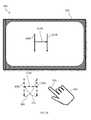
- FIG. 3Aillustrates a system 300 including a computer display 302 and a user's hand 304 .
- the displaymay be the display 208 illustrated in FIG. 2 ; some or all of the remainder of the system of FIG. 2 may also be included in the system 300 of FIG. 3 , but is not pictured for clarity.
- the processor 202is executing, in this implementation, a drawing or text-entry program for interpreting gestures made by the hand 304 as strokes of characters.
- the hand 304performs a series of gestures, including a first drawing gesture 306 A (which the system 300 interprets, using the gesture-recognition module 224 and the systems and methods described above and the cursor-mode module 226 described below) as a first downstoke 306 B of an on-screen H.
- the usernext makes a first movement gesture 308 to set up a second drawing gesture 310 A; the system does not draw anything on the screen 302 corresponding to the first movement gesture 308 but does draw a second on-screen downstroke 310 B for the second drawing gesture 310 A.
- the usermakes a second movement gesture 312 to set up a third drawing gesture 314 A to draw the on-screen cross-stroke 314 B.
- the cursor-mode module 226detects a user intent to switch between drawing and movement modes.
- the cursor-mode module 226analyzes the amount and orientation of curvature present in the path that the hand 304 makes while performing the gestures.
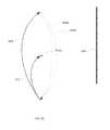
- FIG. 3Billustrates the user gestures in this implementation from a perspective horizontally perpendicular to the perspective shown FIG. 3A .
- the cursor-mode module 226may detect that the drawing gestures 306 A, 310 A, 314 A have little curvature or are straight or nearly straight and the movement gestures 308 , 312 are curved.
- the movement of the hand 304 or a point on the hand 304follows a straighter path through 3D space when making the drawing gestures 306 A, 310 A, 314 A and a more curved path through 3D space when making the movement gestures 308 , 312 .
- the orientation of curvatureis used to determine the intended mode.
- FIG. 3Cillustrates the user gestures in this implementation from a perspective horizontally perpendicular to the perspective shown FIG. 3A .
- the path drawn through 3D space by the hand 304may be curved in a first direction when making the drawing gestures 306 A, 310 A, 314 A (e.g., the midpoint of the curved path is closer to the screen 302 than the endpoints of the curved path) and curved in a second direction when making the movement gestures 308 , 312 (e.g., the midpoints of these curved paths are farther away from the screen 302 than the endpoints).
- the amount of curvatureis use to determine the intended mode. For example, a threshold of curvature may be used to separate a drawing gesture from a movement gesture.
- the amount of curvaturemay be determined by the maximum distance between the path of the curve and an ideal straight line between the endpoints of the gesture.
- An amount of curvature above a threshold of curvaturemay indicate intent to be in the first mode and below intent to be in the second mode.
- the threshold between a first mode and second modemay be a fixed distance (e.g., one to five centimeters).
- the cursor-mode module 226models the path of the gesture as a mathematical curve (e.g., a parabola or elliptical curve) and determines the mode of the gesture based on parameters of the modeled curve (e.g., the axes of the ellipse or coefficients of the parabola).
- the mode of a gestureis determined when the gesture is completed.
- the amount and nature of curvature of the paths of the gestures 306 A, 308 , 310 A, 312 , 314 Amay be determined as the hand 304 begins to trace the paths (i.e., before the gesture is fully completed).
- the cursor-mode module 226may decide the mode of operation of the gestures 306 A, 308 , 310 A, 312 , 314 A after the hand 304 has moved a given distance (e.g., five or ten centimeters) or has completed a certain percentage of a predicted total path distance (e.g., five or ten percent).
- the cursor-mode module 226decides the mode of operation of the gestures 306 A, 308 , 310 A, 312 , 314 A after a given amount of curvature or straightness has been detected (e.g., once a path has deviated by one or two centimeters or five or ten degrees away from a virtual reference plane or line).
- the virtual reference planemay be a vertical plane, or other fixed predetermined plane, and/or may be determined by previous gestures.
- the plane defined by the first drawing gesture 306 Amay be used to determine whether the first movement gesture 308 is straight or curved.
- Additional drawing gestures made by the handmay be used to further define the virtual reference plane; in one implementation, an average of all, or a fixed running average of some, drawing gestures are used to define the reference plane.
- gestures made in which the index finger 316 occupies the same space as the virtual reference planeare deemed to be drawing gestures and gestures made in which the index finger 316 is separated by some distance (e.g., one to five centimeters) from the virtual reference plane at some point during the gesture (e.g., the midpoint) are deemed to be movement gestures.
- the cursor-mode module 226uses the direction in which an object is pointed to determine the mode of operation of the gestures. For example, the direction the index finger 316 is pointing may be used to determine the mode of operation of the gestures 306 A, 308 , 310 A, 312 , 314 A. If the index finger 316 is pointing in a first direction, for example toward a point located above a horizontal plane, when it begins a gesture, the cursor-mode module 226 determines the mode of operation is a drawing mode.
- the cursor-mode module 226may determine the mode of operation is a movement mode. In another implementation, the cursor-mode module 226 switches to drawing mode for downward (or mostly downward) gestures and to movement mode for upward (or mostly upward) gestures.
- the cursor-mode module 226When determining mode the cursor-mode module 226 is not limited to using a single factor and may consider any combination of the disclosed factors including; amount of path curvature, curvature direction/orientation, distance from reference plane, pointing direction, and gesture direction. In implementations using multiple factors to determine mode, factors may be weighted to more heavily influence the mode determination. Further, when determining mode the cursor-mode module 226 is not limited determining between two modes and may use any combination to the factors to determine the mode of operation from more than two modes of operation.
- the gesture-recognition module 224 and/or the cursor-mode module 226may not determine a mode for a gesture until after the object making the gesture has traveled a certain distance in 3D space.
- certain applicationssuch as the drawing application discussed above with reference to FIG. 3 , may display a discontinuity or jolt to a user as this traveled distance is suddenly filled in by the application once the mode is determined to be a drawing mode.
- the drawing applicationinstead of filling in the discontinuity all at once, the drawing application re-traces the already traveled path of the object, drawing in the path at a higher velocity than that traveled by the object.
- the 0-5 cm distanceis filled in from 0 to 5 cm at a rate of 20 cm/s until the filled-in line “catches up” to the object, at which point the drawing rate drops to the object-movement rate.
- the gesture-recognition module 224 and/or the cursor-mode module 226pass position data relating to the object to the drawing application (or any other application) to facilitate this drawing method; for example, no position data is passed until the cursor-mode module 226 determines the mode of the gesture, after which the faster-rate motion is passed until the drawing catches up to the current position of the object, after which normal-rate position information is passed.
- the gesture-recognition module 224 and/or the cursor-mode module 226“guess” a mode of operation before the actual mode of operation is determined.
- the guessmay be to always first assume a drawing mode or a movement mode. In either or both cases, any lines or other markings displayed on the screen 302 during the guessing period may be displayed in a color or shade different from the other lines or markings (e.g., grey instead of black). If the actual mode of operation is drawing the displayed different color becomes the intended color and if the actual mode of operation is movement the displayed different color disappears.
- the guessmay be made based on prior gestures. For example, if the last gesture was a drawing gesture the current gesture may be guessed as movement, and vice versa.
- the cursor-mode module 226may switch modes of a cursor based on multiple tracked objects. For example, a user may make a gesture using two or more fingers (e.g., a “pinching” gesture using a thumb and index finger or a gesture using an index finger on each hand) or using a stylus held in one hand and a finger on the other hand. In these implementations, the cursor-mode module 226 may switch to a mode associated with the particular multi-object gesture even if, for example, only one object intersects the virtual plane discussed above.
- the cursor-mode module 226implements a physics-based computer model to switch between modes.
- the modelmay implement a hysteresis-like effect between the modes.
- small or slow gesturesare interpreted as user intent to stay within the current mode and gestures with similarly shaped paths performed with a range of motion and/or velocity greater than a threshold are interpreted as user intent to switch modes.
- the two modesare a cursor-movement mode and a clicking/interaction mode.
- the gesture-recognition module 224is more sensitive to gestures corresponding to that mode and less sensitive to gestures that do not correspond to that mode.
- the gesture-recognition module 224may register button-pressing motions as clicks even if the button-pressing motions are made using only a user's finger, are made slowly, or are made by the user's finger traveling only a short distance.
- the cursor-mode module 226may require button-pressing motions made with a user's entire hand (or with more than one finger), faster motions, and/or motions made over a greater distance. Motions that the cursor-mode module 226 registers as clicks while in the clicking mode may not be sufficient to enter the clicking mode.
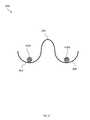
- FIG. 4illustrates a physics-based computer model 400 that the cursor-mode module 226 may implement to switch modes.
- the modelincludes a virtual “hill” 402 having a first “valley” 404 on one side and a second “valley” 406 on its other side.
- a virtual “ball” 408 A, 408 Bexists in either the first 404 or second 406 valley.
- One valleymay be associated with a first mode of operation (e.g., movement) while the other valley may be associated with a second mode of operation (e.g., clicking).
- the intensity, distance, velocity, and/or acceleration of a user gesture“pushes” the ball 408 A, 408 B up the hill 402 .
- Less-intense gesturesdo not push the ball 408 A, 408 B with enough force to surmount the hill 404 and enter the other valley 404 , 406 ; only a more intense gesture may do so, and thereby switch modes. For example, if the ball 408 A is in the first valley 404 , the cursor-mode module 226 selects a movement mode; in order to switch to a clicking mode associated with the second valley 406 , the user must make a clicking motion of greater velocity, acceleration, or distance to enter the clicking mode than would otherwise be required, while in the clicking mode, to create a click.
- Implementationsmay be employed in a variety of application areas, such as for example and without limitation consumer applications including interfaces for computer systems, laptops, tablets, television, game consoles, set top boxes, telephone devices and/or interfaces to other devices; medical applications including controlling devices for performing robotic surgery, medical imaging systems and applications such as CT, ultrasound, x-ray, MRI or the like, laboratory test and diagnostics systems and/or nuclear medicine devices and systems; prosthetics applications including interfaces to devices providing assistance to persons under handicap, disability, recovering from surgery, and/or other infirmity; defense applications including interfaces to aircraft operational controls, navigations systems control, on-board entertainment systems control and/or environmental systems control; automotive applications including interfaces to automobile operational systems control, navigation systems control, on-board entertainment systems control and/or environmental systems control; security applications including, monitoring secure areas for suspicious activity or unauthorized personnel; manufacturing and/or process applications including interfaces to assembly robots, automated test apparatus, work conveyance devices such as conveyors, and/or other factory floor systems and devices, genetic sequencing machines, semiconductor fabrication related machinery, chemical process machinery and/
- Implementations of the technology disclosedmay further be mounted on automobiles or other mobile platforms to provide information to systems therein as to the outside environment (e.g., the positions of other automobiles). Further implementations of the technology disclosed may be used to track the motion of objects in a field of view or used in conjunction with other mobile-tracking systems. Object tracking may be employed, for example, to recognize gestures or to allow the user to interact with a computationally rendered environment; see, e.g., U.S. patent application Ser. No. 61/752,725 (filed on Jan. 15, 2013) and Ser. No. 13/742,953 (filed on Jan. 16, 2013), the entire disclosures of which are hereby incorporated by reference.
- implementations of the technology disclosedmay be provided as one or more computer-readable programs embodied on or in one or more articles of manufacture.
- the article of manufacturemay be any suitable hardware apparatus, such as, for example, a floppy disk, a hard disk, a CD ROM, a CD-RW, a CD-R, a DVD ROM, a DVD-RW, a DVD-R, a flash memory card, a PROM, a RAM, a ROM, or a magnetic tape.
- the computer-readable programsmay be implemented in any programming language. Some examples of languages that may be used include C, C++, or JAVA.
- the software programsmay be further translated into machine language or virtual machine instructions and stored in a program file in that form. The program file may then be stored on or in one or more of the articles of manufacture.
Landscapes
- Engineering & Computer Science (AREA)
- Theoretical Computer Science (AREA)
- General Engineering & Computer Science (AREA)
- Human Computer Interaction (AREA)
- Physics & Mathematics (AREA)
- General Physics & Mathematics (AREA)
- Multimedia (AREA)
- Mechanical Engineering (AREA)
- Health & Medical Sciences (AREA)
- Computer Vision & Pattern Recognition (AREA)
- General Health & Medical Sciences (AREA)
- Psychiatry (AREA)
- Social Psychology (AREA)
- User Interface Of Digital Computer (AREA)
Abstract
Description
Claims (18)
Priority Applications (11)
| Application Number | Priority Date | Filing Date | Title |
|---|---|---|---|
| US14/281,817US9436288B2 (en) | 2013-05-17 | 2014-05-19 | Cursor mode switching |
| US15/213,899US9552075B2 (en) | 2013-05-17 | 2016-07-19 | Cursor mode switching |
| US15/411,909US9927880B2 (en) | 2013-05-17 | 2017-01-20 | Cursor mode switching |
| US15/933,199US10254849B2 (en) | 2013-05-17 | 2018-03-22 | Cursor mode switching |
| US16/377,072US10459530B2 (en) | 2013-05-17 | 2019-04-05 | Cursor mode switching |
| US16/660,528US10901519B2 (en) | 2013-05-17 | 2019-10-22 | Cursor mode switching |
| US17/155,019US11194404B2 (en) | 2013-05-17 | 2021-01-21 | Cursor mode switching |
| US17/542,990US11429194B2 (en) | 2013-05-17 | 2021-12-06 | Cursor mode switching |
| US17/896,619US11720181B2 (en) | 2013-05-17 | 2022-08-26 | Cursor mode switching |
| US18/226,762US12045394B2 (en) | 2013-05-17 | 2023-07-26 | Cursor mode switching |
| US18/776,239US12379787B2 (en) | 2013-05-17 | 2024-07-17 | Cursor mode switching |
Applications Claiming Priority (2)
| Application Number | Priority Date | Filing Date | Title |
|---|---|---|---|
| US201361824691P | 2013-05-17 | 2013-05-17 | |
| US14/281,817US9436288B2 (en) | 2013-05-17 | 2014-05-19 | Cursor mode switching |
Related Child Applications (1)
| Application Number | Title | Priority Date | Filing Date |
|---|---|---|---|
| US15/213,899ContinuationUS9552075B2 (en) | 2013-05-17 | 2016-07-19 | Cursor mode switching |
Publications (2)
| Publication Number | Publication Date |
|---|---|
| US20140340311A1 US20140340311A1 (en) | 2014-11-20 |
| US9436288B2true US9436288B2 (en) | 2016-09-06 |
Family
ID=56886265
Family Applications (11)
| Application Number | Title | Priority Date | Filing Date |
|---|---|---|---|
| US14/281,817Active2034-07-14US9436288B2 (en) | 2013-05-17 | 2014-05-19 | Cursor mode switching |
| US15/213,899ActiveUS9552075B2 (en) | 2013-05-17 | 2016-07-19 | Cursor mode switching |
| US15/411,909ActiveUS9927880B2 (en) | 2013-05-17 | 2017-01-20 | Cursor mode switching |
| US15/933,199ActiveUS10254849B2 (en) | 2013-05-17 | 2018-03-22 | Cursor mode switching |
| US16/377,072ActiveUS10459530B2 (en) | 2013-05-17 | 2019-04-05 | Cursor mode switching |
| US16/660,528ActiveUS10901519B2 (en) | 2013-05-17 | 2019-10-22 | Cursor mode switching |
| US17/155,019ActiveUS11194404B2 (en) | 2013-05-17 | 2021-01-21 | Cursor mode switching |
| US17/542,990ActiveUS11429194B2 (en) | 2013-05-17 | 2021-12-06 | Cursor mode switching |
| US17/896,619ActiveUS11720181B2 (en) | 2013-05-17 | 2022-08-26 | Cursor mode switching |
| US18/226,762ActiveUS12045394B2 (en) | 2013-05-17 | 2023-07-26 | Cursor mode switching |
| US18/776,239ActiveUS12379787B2 (en) | 2013-05-17 | 2024-07-17 | Cursor mode switching |
Family Applications After (10)
| Application Number | Title | Priority Date | Filing Date |
|---|---|---|---|
| US15/213,899ActiveUS9552075B2 (en) | 2013-05-17 | 2016-07-19 | Cursor mode switching |
| US15/411,909ActiveUS9927880B2 (en) | 2013-05-17 | 2017-01-20 | Cursor mode switching |
| US15/933,199ActiveUS10254849B2 (en) | 2013-05-17 | 2018-03-22 | Cursor mode switching |
| US16/377,072ActiveUS10459530B2 (en) | 2013-05-17 | 2019-04-05 | Cursor mode switching |
| US16/660,528ActiveUS10901519B2 (en) | 2013-05-17 | 2019-10-22 | Cursor mode switching |
| US17/155,019ActiveUS11194404B2 (en) | 2013-05-17 | 2021-01-21 | Cursor mode switching |
| US17/542,990ActiveUS11429194B2 (en) | 2013-05-17 | 2021-12-06 | Cursor mode switching |
| US17/896,619ActiveUS11720181B2 (en) | 2013-05-17 | 2022-08-26 | Cursor mode switching |
| US18/226,762ActiveUS12045394B2 (en) | 2013-05-17 | 2023-07-26 | Cursor mode switching |
| US18/776,239ActiveUS12379787B2 (en) | 2013-05-17 | 2024-07-17 | Cursor mode switching |
Country Status (1)
| Country | Link |
|---|---|
| US (11) | US9436288B2 (en) |
Cited By (15)
| Publication number | Priority date | Publication date | Assignee | Title |
|---|---|---|---|---|
| US20140344731A1 (en)* | 2013-05-17 | 2014-11-20 | Leap Motion, Inc. | Dynamic interactive objects |
| US20170061205A1 (en)* | 2012-01-17 | 2017-03-02 | Leap Motion, Inc. | Enhanced Contrast for Object Detection and Characterization By Optical Imaging Based on Differences Between Images |
| US9632658B2 (en) | 2013-01-15 | 2017-04-25 | Leap Motion, Inc. | Dynamic user interactions for display control and scaling responsiveness of display objects |
| US9747696B2 (en) | 2013-05-17 | 2017-08-29 | Leap Motion, Inc. | Systems and methods for providing normalized parameters of motions of objects in three-dimensional space |
| US9927880B2 (en)* | 2013-05-17 | 2018-03-27 | Leap Motion, Inc. | Cursor mode switching |
| US10620709B2 (en) | 2013-04-05 | 2020-04-14 | Ultrahaptics IP Two Limited | Customized gesture interpretation |
| US11048329B1 (en) | 2017-07-27 | 2021-06-29 | Emerge Now Inc. | Mid-air ultrasonic haptic interface for immersive computing environments |
| US11720180B2 (en) | 2012-01-17 | 2023-08-08 | Ultrahaptics IP Two Limited | Systems and methods for machine control |
| US11875012B2 (en) | 2018-05-25 | 2024-01-16 | Ultrahaptics IP Two Limited | Throwable interface for augmented reality and virtual reality environments |
| US12032746B2 (en) | 2015-02-13 | 2024-07-09 | Ultrahaptics IP Two Limited | Systems and methods of creating a realistic displacement of a virtual object in virtual reality/augmented reality environments |
| US12118134B2 (en) | 2015-02-13 | 2024-10-15 | Ultrahaptics IP Two Limited | Interaction engine for creating a realistic experience in virtual reality/augmented reality environments |
| US12131011B2 (en) | 2013-10-29 | 2024-10-29 | Ultrahaptics IP Two Limited | Virtual interactions for machine control |
| US12164694B2 (en) | 2013-10-31 | 2024-12-10 | Ultrahaptics IP Two Limited | Interactions with virtual objects for machine control |
| US12260023B2 (en) | 2012-01-17 | 2025-03-25 | Ultrahaptics IP Two Limited | Systems and methods for machine control |
| US12306301B2 (en) | 2013-03-15 | 2025-05-20 | Ultrahaptics IP Two Limited | Determining positional information of an object in space |
Families Citing this family (8)
| Publication number | Priority date | Publication date | Assignee | Title |
|---|---|---|---|---|
| WO2014205632A1 (en)* | 2013-06-24 | 2014-12-31 | Adobe Systems Incorporated | Gravity point drawing method |
| KR101595958B1 (en)* | 2014-08-27 | 2016-02-18 | 엘지전자 주식회사 | Image display device and operation method of the image display device |
| KR102339839B1 (en)* | 2014-12-26 | 2021-12-15 | 삼성전자주식회사 | Method and apparatus for processing gesture input |
| EP3243120A4 (en)* | 2015-01-09 | 2018-08-22 | Razer (Asia-Pacific) Pte Ltd. | Gesture recognition devices and gesture recognition methods |
| JP6617417B2 (en)* | 2015-03-05 | 2019-12-11 | セイコーエプソン株式会社 | Display device and display device control method |
| US11157152B2 (en)* | 2018-11-05 | 2021-10-26 | Sap Se | Interaction mechanisms for pointer control |
| US11182073B2 (en) | 2018-11-28 | 2021-11-23 | International Business Machines Corporation | Selection on user interface based on cursor gestures |
| CN112650846B (en)* | 2021-01-13 | 2024-08-23 | 北京智通云联科技有限公司 | Question and answer intention knowledge base construction system and method based on question frame |
Citations (22)
| Publication number | Priority date | Publication date | Assignee | Title |
|---|---|---|---|---|
| US20030081141A1 (en) | 2001-09-17 | 2003-05-01 | Douglas Mazzapica | Brightness adjustment method |
| US6901170B1 (en) | 2000-09-05 | 2005-05-31 | Fuji Xerox Co., Ltd. | Image processing device and recording medium |
| US20090217211A1 (en) | 2008-02-27 | 2009-08-27 | Gesturetek, Inc. | Enhanced input using recognized gestures |
| US20110119640A1 (en) | 2009-11-19 | 2011-05-19 | Microsoft Corporation | Distance scalable no touch computing |
| US20110251896A1 (en) | 2010-04-09 | 2011-10-13 | Affine Systems, Inc. | Systems and methods for matching an advertisement to a video |
| US8235529B1 (en)* | 2011-11-30 | 2012-08-07 | Google Inc. | Unlocking a screen using eye tracking information |
| US20120204133A1 (en) | 2009-01-13 | 2012-08-09 | Primesense Ltd. | Gesture-Based User Interface |
| US20120320080A1 (en)* | 2011-06-14 | 2012-12-20 | Microsoft Corporation | Motion based virtual object navigation |
| US20130191911A1 (en)* | 2012-01-20 | 2013-07-25 | Apple Inc. | Device, Method, and Graphical User Interface for Accessing an Application in a Locked Device |
| US20130222640A1 (en)* | 2012-02-27 | 2013-08-29 | Samsung Electronics Co., Ltd. | Moving image shooting apparatus and method of using a camera device |
| US20130239059A1 (en) | 2012-03-06 | 2013-09-12 | Acer Incorporated | Touch screen folder control |
| US20130307935A1 (en)* | 2011-02-01 | 2013-11-21 | National University Of Singapore | Imaging system and method |
| US20140125813A1 (en) | 2012-11-08 | 2014-05-08 | David Holz | Object detection and tracking with variable-field illumination devices |
| US20140134733A1 (en) | 2012-11-13 | 2014-05-15 | The Board Of Trustees Of The Leland Stanford Junior University | Chemically defined production of cardiomyocytes from pluripotent stem cells |
| US20140157135A1 (en) | 2012-12-03 | 2014-06-05 | Samsung Electronics Co., Ltd. | Method and mobile terminal for controlling bluetooth low energy device |
| US20140223385A1 (en) | 2013-02-05 | 2014-08-07 | Qualcomm Incorporated | Methods for system engagement via 3d object detection |
| US20140240215A1 (en) | 2013-02-26 | 2014-08-28 | Corel Corporation | System and method for controlling a user interface utility using a vision system |
| US20140344762A1 (en)* | 2013-05-14 | 2014-11-20 | Qualcomm Incorporated | Augmented reality (ar) capture & play |
| US20150003673A1 (en) | 2013-07-01 | 2015-01-01 | Hand Held Products, Inc. | Dimensioning system |
| US20150084864A1 (en)* | 2012-01-09 | 2015-03-26 | Google Inc. | Input Method |
| US9056396B1 (en) | 2013-03-05 | 2015-06-16 | Autofuss | Programming of a robotic arm using a motion capture system |
| US20150227795A1 (en) | 2012-01-06 | 2015-08-13 | Google Inc. | Object Outlining to Initiate a Visual Search |
Family Cites Families (36)
| Publication number | Priority date | Publication date | Assignee | Title |
|---|---|---|---|---|
| US6266061B1 (en) | 1997-01-22 | 2001-07-24 | Kabushiki Kaisha Toshiba | User interface apparatus and operation range presenting method |
| US5901170A (en) | 1997-05-01 | 1999-05-04 | Inductotherm Corp. | Induction furnace |
| US20020063740A1 (en) | 2000-11-30 | 2002-05-30 | Forlenza Randolph Michael | Method to unobscure vision caused by the mouse pointer positioning within a document being displayed by a computer system |
| US7886236B2 (en) | 2003-03-28 | 2011-02-08 | Microsoft Corporation | Dynamic feedback for gestures |
| NZ546169A (en) | 2006-03-24 | 2008-12-24 | Pacer Turbines Ltd | Power generator |
| US8217895B2 (en) | 2006-04-28 | 2012-07-10 | Mtekvision Co., Ltd. | Non-contact selection device |
| US8316324B2 (en) | 2006-09-05 | 2012-11-20 | Navisense | Method and apparatus for touchless control of a device |
| JP4569613B2 (en) | 2007-09-19 | 2010-10-27 | ソニー株式会社 | Image processing apparatus, image processing method, and program |
| FR2936326B1 (en) | 2008-09-22 | 2011-04-29 | Stantum | DEVICE FOR THE CONTROL OF ELECTRONIC APPARATUS BY HANDLING GRAPHIC OBJECTS ON A MULTICONTACT TOUCH SCREEN |
| US8671365B2 (en) | 2008-11-26 | 2014-03-11 | Nokia Corporation | Method, apparatus and computer program product for providing a cursor for indicating context data in a mapping application |
| US8446376B2 (en) | 2009-01-13 | 2013-05-21 | Microsoft Corporation | Visual response to touch inputs |
| US8917239B2 (en) | 2012-10-14 | 2014-12-23 | Neonode Inc. | Removable protective cover with embedded proximity sensors |
| US8643628B1 (en) | 2012-10-14 | 2014-02-04 | Neonode Inc. | Light-based proximity detection system and user interface |
| US20100235786A1 (en) | 2009-03-13 | 2010-09-16 | Primesense Ltd. | Enhanced 3d interfacing for remote devices |
| US8928578B2 (en) | 2009-04-29 | 2015-01-06 | Microsoft Corporation | Cursor adjustment in ambient light |
| US8341558B2 (en) | 2009-09-16 | 2012-12-25 | Google Inc. | Gesture recognition on computing device correlating input to a template |
| US8878779B2 (en) | 2009-09-21 | 2014-11-04 | Extreme Reality Ltd. | Methods circuits device systems and associated computer executable code for facilitating interfacing with a computing platform display screen |
| US8230852B2 (en) | 2010-05-28 | 2012-07-31 | Honeywell International Inc. | Shoulder mounted hood cooling system |
| EP2394710B1 (en) | 2010-06-11 | 2020-06-10 | BANDAI NAMCO Entertainment Inc. | Image generation system, image generation method, and information storage medium |
| US8508347B2 (en) | 2010-06-24 | 2013-08-13 | Nokia Corporation | Apparatus and method for proximity based input |
| KR101708696B1 (en) | 2010-09-15 | 2017-02-21 | 엘지전자 주식회사 | Mobile terminal and operation control method thereof |
| US9047006B2 (en) | 2010-09-29 | 2015-06-02 | Sony Corporation | Electronic device system with information processing mechanism and method of operation thereof |
| EP2672880B1 (en) | 2011-02-09 | 2019-05-22 | Apple Inc. | Gaze detection in a 3d mapping environment |
| EP2678764A4 (en) | 2011-02-22 | 2017-03-22 | Hewlett-Packard Development Company, L.P. | Control area for facilitating user input |
| US9317130B2 (en) | 2011-06-16 | 2016-04-19 | Rafal Jan Krepec | Visual feedback by identifying anatomical features of a hand |
| DE102011112447A1 (en) | 2011-09-03 | 2013-03-07 | Volkswagen Aktiengesellschaft | Method and arrangement for providing a graphical user interface, in particular in a vehicle |
| US9372593B2 (en) | 2011-11-29 | 2016-06-21 | Apple Inc. | Using a three-dimensional model to render a cursor |
| US20150220149A1 (en) | 2012-02-14 | 2015-08-06 | Google Inc. | Systems and methods for a virtual grasping user interface |
| US20150220150A1 (en) | 2012-02-14 | 2015-08-06 | Google Inc. | Virtual touch user interface system and methods |
| KR20130095970A (en) | 2012-02-21 | 2013-08-29 | 삼성전자주식회사 | Apparatus and method for controlling object in device with touch screen |
| CN108469899B (en) | 2012-03-13 | 2021-08-10 | 视力移动技术有限公司 | Method of identifying an aiming point or area in a viewing space of a wearable display device |
| KR102092234B1 (en) | 2012-08-03 | 2020-03-23 | 엘지전자 주식회사 | Mobile terminal and control method thereof |
| FR2998071B1 (en) | 2012-11-09 | 2014-11-21 | Thales Sa | METHOD FOR SECURING A CONTROL ON A TOUCH-SURFACE VISUALIZATION DEVICE AND SYSTEM THEREOF |
| US9459697B2 (en) | 2013-01-15 | 2016-10-04 | Leap Motion, Inc. | Dynamic, free-space user interactions for machine control |
| US9436288B2 (en)* | 2013-05-17 | 2016-09-06 | Leap Motion, Inc. | Cursor mode switching |
| US10620775B2 (en) | 2013-05-17 | 2020-04-14 | Ultrahaptics IP Two Limited | Dynamic interactive objects |
- 2014
- 2014-05-19USUS14/281,817patent/US9436288B2/enactiveActive
- 2016
- 2016-07-19USUS15/213,899patent/US9552075B2/enactiveActive
- 2017
- 2017-01-20USUS15/411,909patent/US9927880B2/enactiveActive
- 2018
- 2018-03-22USUS15/933,199patent/US10254849B2/enactiveActive
- 2019
- 2019-04-05USUS16/377,072patent/US10459530B2/enactiveActive
- 2019-10-22USUS16/660,528patent/US10901519B2/enactiveActive
- 2021
- 2021-01-21USUS17/155,019patent/US11194404B2/enactiveActive
- 2021-12-06USUS17/542,990patent/US11429194B2/enactiveActive
- 2022
- 2022-08-26USUS17/896,619patent/US11720181B2/enactiveActive
- 2023
- 2023-07-26USUS18/226,762patent/US12045394B2/enactiveActive
- 2024
- 2024-07-17USUS18/776,239patent/US12379787B2/enactiveActive
Patent Citations (23)
| Publication number | Priority date | Publication date | Assignee | Title |
|---|---|---|---|---|
| US6901170B1 (en) | 2000-09-05 | 2005-05-31 | Fuji Xerox Co., Ltd. | Image processing device and recording medium |
| US20030081141A1 (en) | 2001-09-17 | 2003-05-01 | Douglas Mazzapica | Brightness adjustment method |
| US20090217211A1 (en) | 2008-02-27 | 2009-08-27 | Gesturetek, Inc. | Enhanced input using recognized gestures |
| US20120204133A1 (en) | 2009-01-13 | 2012-08-09 | Primesense Ltd. | Gesture-Based User Interface |
| US20110119640A1 (en) | 2009-11-19 | 2011-05-19 | Microsoft Corporation | Distance scalable no touch computing |
| US20110251896A1 (en) | 2010-04-09 | 2011-10-13 | Affine Systems, Inc. | Systems and methods for matching an advertisement to a video |
| US20130307935A1 (en)* | 2011-02-01 | 2013-11-21 | National University Of Singapore | Imaging system and method |
| US20120320080A1 (en)* | 2011-06-14 | 2012-12-20 | Microsoft Corporation | Motion based virtual object navigation |
| US8235529B1 (en)* | 2011-11-30 | 2012-08-07 | Google Inc. | Unlocking a screen using eye tracking information |
| US20150227795A1 (en) | 2012-01-06 | 2015-08-13 | Google Inc. | Object Outlining to Initiate a Visual Search |
| US20150084864A1 (en)* | 2012-01-09 | 2015-03-26 | Google Inc. | Input Method |
| US20130191911A1 (en)* | 2012-01-20 | 2013-07-25 | Apple Inc. | Device, Method, and Graphical User Interface for Accessing an Application in a Locked Device |
| US20130222640A1 (en)* | 2012-02-27 | 2013-08-29 | Samsung Electronics Co., Ltd. | Moving image shooting apparatus and method of using a camera device |
| US20130239059A1 (en) | 2012-03-06 | 2013-09-12 | Acer Incorporated | Touch screen folder control |
| US8930852B2 (en) | 2012-03-06 | 2015-01-06 | Acer Incorporated | Touch screen folder control |
| US20140125813A1 (en) | 2012-11-08 | 2014-05-08 | David Holz | Object detection and tracking with variable-field illumination devices |
| US20140134733A1 (en) | 2012-11-13 | 2014-05-15 | The Board Of Trustees Of The Leland Stanford Junior University | Chemically defined production of cardiomyocytes from pluripotent stem cells |
| US20140157135A1 (en) | 2012-12-03 | 2014-06-05 | Samsung Electronics Co., Ltd. | Method and mobile terminal for controlling bluetooth low energy device |
| US20140223385A1 (en) | 2013-02-05 | 2014-08-07 | Qualcomm Incorporated | Methods for system engagement via 3d object detection |
| US20140240215A1 (en) | 2013-02-26 | 2014-08-28 | Corel Corporation | System and method for controlling a user interface utility using a vision system |
| US9056396B1 (en) | 2013-03-05 | 2015-06-16 | Autofuss | Programming of a robotic arm using a motion capture system |
| US20140344762A1 (en)* | 2013-05-14 | 2014-11-20 | Qualcomm Incorporated | Augmented reality (ar) capture & play |
| US20150003673A1 (en) | 2013-07-01 | 2015-01-01 | Hand Held Products, Inc. | Dimensioning system |
Non-Patent Citations (2)
| Title |
|---|
| U.S. Appl. No. 14/154,730-Office Action, Nov. 6, 2015, 9 pages. |
| U.S. Appl. No. 14/262,691-Office Action, Dec. 11, 2015, 31 pages. |
Cited By (42)
| Publication number | Priority date | Publication date | Assignee | Title |
|---|---|---|---|---|
| US10366308B2 (en) | 2012-01-17 | 2019-07-30 | Leap Motion, Inc. | Enhanced contrast for object detection and characterization by optical imaging based on differences between images |
| US20170061205A1 (en)* | 2012-01-17 | 2017-03-02 | Leap Motion, Inc. | Enhanced Contrast for Object Detection and Characterization By Optical Imaging Based on Differences Between Images |
| US10699155B2 (en) | 2012-01-17 | 2020-06-30 | Ultrahaptics IP Two Limited | Enhanced contrast for object detection and characterization by optical imaging based on differences between images |
| US9652668B2 (en)* | 2012-01-17 | 2017-05-16 | Leap Motion, Inc. | Enhanced contrast for object detection and characterization by optical imaging based on differences between images |
| US11720180B2 (en) | 2012-01-17 | 2023-08-08 | Ultrahaptics IP Two Limited | Systems and methods for machine control |
| US12260023B2 (en) | 2012-01-17 | 2025-03-25 | Ultrahaptics IP Two Limited | Systems and methods for machine control |
| US9934580B2 (en)* | 2012-01-17 | 2018-04-03 | Leap Motion, Inc. | Enhanced contrast for object detection and characterization by optical imaging based on differences between images |
| US11308711B2 (en) | 2012-01-17 | 2022-04-19 | Ultrahaptics IP Two Limited | Enhanced contrast for object detection and characterization by optical imaging based on differences between images |
| US11782516B2 (en) | 2012-01-17 | 2023-10-10 | Ultrahaptics IP Two Limited | Differentiating a detected object from a background using a gaussian brightness falloff pattern |
| US12086327B2 (en) | 2012-01-17 | 2024-09-10 | Ultrahaptics IP Two Limited | Differentiating a detected object from a background using a gaussian brightness falloff pattern |
| US11269481B2 (en) | 2013-01-15 | 2022-03-08 | Ultrahaptics IP Two Limited | Dynamic user interactions for display control and measuring degree of completeness of user gestures |
| US10241639B2 (en) | 2013-01-15 | 2019-03-26 | Leap Motion, Inc. | Dynamic user interactions for display control and manipulation of display objects |
| US10042510B2 (en) | 2013-01-15 | 2018-08-07 | Leap Motion, Inc. | Dynamic user interactions for display control and measuring degree of completeness of user gestures |
| US10817130B2 (en) | 2013-01-15 | 2020-10-27 | Ultrahaptics IP Two Limited | Dynamic user interactions for display control and measuring degree of completeness of user gestures |
| US9632658B2 (en) | 2013-01-15 | 2017-04-25 | Leap Motion, Inc. | Dynamic user interactions for display control and scaling responsiveness of display objects |
| US10782847B2 (en) | 2013-01-15 | 2020-09-22 | Ultrahaptics IP Two Limited | Dynamic user interactions for display control and scaling responsiveness of display objects |
| US12306301B2 (en) | 2013-03-15 | 2025-05-20 | Ultrahaptics IP Two Limited | Determining positional information of an object in space |
| US11347317B2 (en) | 2013-04-05 | 2022-05-31 | Ultrahaptics IP Two Limited | Customized gesture interpretation |
| US10620709B2 (en) | 2013-04-05 | 2020-04-14 | Ultrahaptics IP Two Limited | Customized gesture interpretation |
| US11194404B2 (en)* | 2013-05-17 | 2021-12-07 | Ultrahaptics IP Two Limited | Cursor mode switching |
| US11720181B2 (en) | 2013-05-17 | 2023-08-08 | Ultrahaptics IP Two Limited | Cursor mode switching |
| US9927880B2 (en)* | 2013-05-17 | 2018-03-27 | Leap Motion, Inc. | Cursor mode switching |
| US11275480B2 (en) | 2013-05-17 | 2022-03-15 | Ultrahaptics IP Two Limited | Dynamic interactive objects |
| US10936145B2 (en) | 2013-05-17 | 2021-03-02 | Ultrahaptics IP Two Limited | Dynamic interactive objects |
| US10901519B2 (en)* | 2013-05-17 | 2021-01-26 | Ultrahaptics IP Two Limited | Cursor mode switching |
| US20140344731A1 (en)* | 2013-05-17 | 2014-11-20 | Leap Motion, Inc. | Dynamic interactive objects |
| US11429194B2 (en) | 2013-05-17 | 2022-08-30 | Ultrahaptics IP Two Limited | Cursor mode switching |
| US10620775B2 (en)* | 2013-05-17 | 2020-04-14 | Ultrahaptics IP Two Limited | Dynamic interactive objects |
| US9747696B2 (en) | 2013-05-17 | 2017-08-29 | Leap Motion, Inc. | Systems and methods for providing normalized parameters of motions of objects in three-dimensional space |
| US10459530B2 (en) | 2013-05-17 | 2019-10-29 | Ultrahaptics IP Two Limited | Cursor mode switching |
| US12379787B2 (en) | 2013-05-17 | 2025-08-05 | Ultrahaptics IP Two Limited | Cursor mode switching |
| US10254849B2 (en) | 2013-05-17 | 2019-04-09 | Leap Motion, Inc. | Cursor mode switching |
| US12045394B2 (en) | 2013-05-17 | 2024-07-23 | Ultrahaptics IP Two Limited | Cursor mode switching |
| US12131011B2 (en) | 2013-10-29 | 2024-10-29 | Ultrahaptics IP Two Limited | Virtual interactions for machine control |
| US12164694B2 (en) | 2013-10-31 | 2024-12-10 | Ultrahaptics IP Two Limited | Interactions with virtual objects for machine control |
| US12032746B2 (en) | 2015-02-13 | 2024-07-09 | Ultrahaptics IP Two Limited | Systems and methods of creating a realistic displacement of a virtual object in virtual reality/augmented reality environments |
| US12118134B2 (en) | 2015-02-13 | 2024-10-15 | Ultrahaptics IP Two Limited | Interaction engine for creating a realistic experience in virtual reality/augmented reality environments |
| US12386430B2 (en) | 2015-02-13 | 2025-08-12 | Ultrahaptics IP Two Limited | Systems and methods of creating a realistic displacement of a virtual object in virtual reality/augmented reality environments |
| US11392206B2 (en) | 2017-07-27 | 2022-07-19 | Emerge Now Inc. | Mid-air ultrasonic haptic interface for immersive computing environments |
| US11048329B1 (en) | 2017-07-27 | 2021-06-29 | Emerge Now Inc. | Mid-air ultrasonic haptic interface for immersive computing environments |
| US11875012B2 (en) | 2018-05-25 | 2024-01-16 | Ultrahaptics IP Two Limited | Throwable interface for augmented reality and virtual reality environments |
| US12393316B2 (en) | 2018-05-25 | 2025-08-19 | Ultrahaptics IP Two Limited | Throwable interface for augmented reality and virtual reality environments |
Also Published As
| Publication number | Publication date |
|---|---|
| US20230367399A1 (en) | 2023-11-16 |
| US11720181B2 (en) | 2023-08-08 |
| US12045394B2 (en) | 2024-07-23 |
| US10254849B2 (en) | 2019-04-09 |
| US20140340311A1 (en) | 2014-11-20 |
| US11429194B2 (en) | 2022-08-30 |
| US10459530B2 (en) | 2019-10-29 |
| US20240370097A1 (en) | 2024-11-07 |
| US20170131784A1 (en) | 2017-05-11 |
| US20190018497A1 (en) | 2019-01-17 |
| US10901519B2 (en) | 2021-01-26 |
| US20200159334A1 (en) | 2020-05-21 |
| US20220404917A1 (en) | 2022-12-22 |
| US9927880B2 (en) | 2018-03-27 |
| US11194404B2 (en) | 2021-12-07 |
| US9552075B2 (en) | 2017-01-24 |
| US20220091680A1 (en) | 2022-03-24 |
| US20160328022A1 (en) | 2016-11-10 |
| US20190235633A1 (en) | 2019-08-01 |
| US12379787B2 (en) | 2025-08-05 |
| US20210173490A1 (en) | 2021-06-10 |
Similar Documents
| Publication | Publication Date | Title |
|---|---|---|
| US12379787B2 (en) | Cursor mode switching | |
| US11275480B2 (en) | Dynamic interactive objects | |
| US12086323B2 (en) | Determining a primary control mode of controlling an electronic device using 3D gestures or using control manipulations from a user manipulable input device | |
| US11567578B2 (en) | Systems and methods of free-space gestural interaction | |
| US10638036B2 (en) | Adjusting motion capture based on the distance between tracked objects | |
| CN105229582B (en) | Gesture detection based on proximity sensor and image sensor | |
| US9747696B2 (en) | Systems and methods for providing normalized parameters of motions of objects in three-dimensional space |
Legal Events
| Date | Code | Title | Description |
|---|---|---|---|
| AS | Assignment | Owner name:LEAP MOTION, INC., CALIFORNIA Free format text:ASSIGNMENT OF ASSIGNORS INTEREST;ASSIGNOR:HOLZ, DAVID S.;REEL/FRAME:035511/0245 Effective date:20150211 | |
| AS | Assignment | Owner name:TRIPLEPOINT CAPITAL LLC, CALIFORNIA Free format text:SECURITY INTEREST;ASSIGNOR:LEAP MOTION, INC.;REEL/FRAME:036644/0314 Effective date:20150918 | |
| AS | Assignment | Owner name:THE FOUNDERS FUND IV, LP, CALIFORNIA Free format text:SECURITY INTEREST;ASSIGNOR:LEAP MOTION, INC.;REEL/FRAME:036796/0151 Effective date:20150918 | |
| STCF | Information on status: patent grant | Free format text:PATENTED CASE | |
| CC | Certificate of correction | ||
| AS | Assignment | Owner name:LEAP MOTION, INC., CALIFORNIA Free format text:TERMINATION OF SECURITY AGREEMENT;ASSIGNOR:THE FOUNDERS FUND IV, LP, AS COLLATERAL AGENT;REEL/FRAME:047444/0567 Effective date:20181101 | |
| AS | Assignment | Owner name:HAYNES BEFFEL WOLFELD LLP, CALIFORNIA Free format text:SECURITY INTEREST;ASSIGNOR:LEAP MOTION, INC.;REEL/FRAME:048919/0109 Effective date:20190411 | |
| AS | Assignment | Owner name:LEAP MOTION, INC., CALIFORNIA Free format text:RELEASE BY SECURED PARTY;ASSIGNOR:TRIPLEPOINT CAPITAL LLC;REEL/FRAME:049337/0130 Effective date:20190524 | |
| AS | Assignment | Owner name:LEAP MOTION, INC., CALIFORNIA Free format text:RELEASE BY SECURED PARTY;ASSIGNOR:HAYNES BEFFEL WOLFELD LLP;REEL/FRAME:049926/0631 Effective date:20190731 | |
| AS | Assignment | Owner name:ULTRAHAPTICS IP TWO LIMITED, UNITED KINGDOM Free format text:ASSIGNMENT OF ASSIGNORS INTEREST;ASSIGNOR:LMI LIQUIDATING CO., LLC.;REEL/FRAME:051580/0165 Effective date:20190930 Owner name:LMI LIQUIDATING CO., LLC., CALIFORNIA Free format text:ASSIGNMENT OF ASSIGNORS INTEREST;ASSIGNOR:LEAP MOTION, INC.;REEL/FRAME:052914/0871 Effective date:20190930 | |
| MAFP | Maintenance fee payment | Free format text:PAYMENT OF MAINTENANCE FEE, 4TH YR, SMALL ENTITY (ORIGINAL EVENT CODE: M2551); ENTITY STATUS OF PATENT OWNER: SMALL ENTITY Year of fee payment:4 | |
| AS | Assignment | Owner name:LMI LIQUIDATING CO., LLC, CALIFORNIA Free format text:SECURITY INTEREST;ASSIGNOR:ULTRAHAPTICS IP TWO LIMITED;REEL/FRAME:052848/0240 Effective date:20190524 | |
| AS | Assignment | Owner name:TRIPLEPOINT CAPITAL LLC, CALIFORNIA Free format text:SECURITY INTEREST;ASSIGNOR:LMI LIQUIDATING CO., LLC;REEL/FRAME:052902/0571 Effective date:20191228 | |
| FEPP | Fee payment procedure | Free format text:ENTITY STATUS SET TO UNDISCOUNTED (ORIGINAL EVENT CODE: BIG.); ENTITY STATUS OF PATENT OWNER: LARGE ENTITY | |
| MAFP | Maintenance fee payment | Free format text:PAYMENT OF MAINTENANCE FEE, 8TH YEAR, LARGE ENTITY (ORIGINAL EVENT CODE: M1552); ENTITY STATUS OF PATENT OWNER: LARGE ENTITY Year of fee payment:8 |