US9435976B2 - Adapter panel with lateral sliding adapter arrays - Google Patents
Adapter panel with lateral sliding adapter arraysDownload PDFInfo
- Publication number
- US9435976B2 US9435976B2US14/813,697US201514813697AUS9435976B2US 9435976 B2US9435976 B2US 9435976B2US 201514813697 AUS201514813697 AUS 201514813697AUS 9435976 B2US9435976 B2US 9435976B2
- Authority
- US
- United States
- Prior art keywords
- sliding member
- adapters
- row
- chassis
- arrangement
- Prior art date
- Legal status (The legal status is an assumption and is not a legal conclusion. Google has not performed a legal analysis and makes no representation as to the accuracy of the status listed.)
- Active
Links
Images


Classifications
- H—ELECTRICITY
- H04—ELECTRIC COMMUNICATION TECHNIQUE
- H04Q—SELECTING
- H04Q1/00—Details of selecting apparatus or arrangements
- H04Q1/02—Constructional details
- H04Q1/14—Distribution frames
- H04Q1/142—Terminal blocks for distribution frames
- G—PHYSICS
- G02—OPTICS
- G02B—OPTICAL ELEMENTS, SYSTEMS OR APPARATUS
- G02B6/00—Light guides; Structural details of arrangements comprising light guides and other optical elements, e.g. couplings
- G02B6/24—Coupling light guides
- G02B6/36—Mechanical coupling means
- G02B6/38—Mechanical coupling means having fibre to fibre mating means
- G02B6/3807—Dismountable connectors, i.e. comprising plugs
- G02B6/381—Dismountable connectors, i.e. comprising plugs of the ferrule type, e.g. fibre ends embedded in ferrules, connecting a pair of fibres
- G02B6/3825—Dismountable connectors, i.e. comprising plugs of the ferrule type, e.g. fibre ends embedded in ferrules, connecting a pair of fibres with an intermediate part, e.g. adapter, receptacle, linking two plugs
- G—PHYSICS
- G02—OPTICS
- G02B—OPTICAL ELEMENTS, SYSTEMS OR APPARATUS
- G02B6/00—Light guides; Structural details of arrangements comprising light guides and other optical elements, e.g. couplings
- G02B6/44—Mechanical structures for providing tensile strength and external protection for fibres, e.g. optical transmission cables
- G02B6/4439—Auxiliary devices
- G02B6/444—Systems or boxes with surplus lengths
- G02B6/4441—Boxes
- G02B6/4446—Cable boxes, e.g. splicing boxes with two or more multi fibre cables
- G—PHYSICS
- G02—OPTICS
- G02B—OPTICAL ELEMENTS, SYSTEMS OR APPARATUS
- G02B6/00—Light guides; Structural details of arrangements comprising light guides and other optical elements, e.g. couplings
- G02B6/44—Mechanical structures for providing tensile strength and external protection for fibres, e.g. optical transmission cables
- G02B6/4439—Auxiliary devices
- G02B6/444—Systems or boxes with surplus lengths
- G02B6/4452—Distribution frames
- G02B6/44526—Panels or rackmounts covering a whole width of the frame or rack
- G—PHYSICS
- G02—OPTICS
- G02B—OPTICAL ELEMENTS, SYSTEMS OR APPARATUS
- G02B6/00—Light guides; Structural details of arrangements comprising light guides and other optical elements, e.g. couplings
- G02B6/44—Mechanical structures for providing tensile strength and external protection for fibres, e.g. optical transmission cables
- G02B6/4439—Auxiliary devices
- G02B6/444—Systems or boxes with surplus lengths
- G02B6/4453—Cassettes
- G02B6/4455—Cassettes characterised by the way of extraction or insertion of the cassette in the distribution frame, e.g. pivoting, sliding, rotating or gliding
- H—ELECTRICITY
- H04—ELECTRIC COMMUNICATION TECHNIQUE
- H04Q—SELECTING
- H04Q1/00—Details of selecting apparatus or arrangements
- H04Q1/02—Constructional details
- H04Q1/023—Constructional details using sliding mechanisms for accessing the interior of the apparatus
- H—ELECTRICITY
- H04—ELECTRIC COMMUNICATION TECHNIQUE
- H04Q—SELECTING
- H04Q1/00—Details of selecting apparatus or arrangements
- H04Q1/02—Constructional details
- H04Q1/06—Cable ducts or mountings specially adapted for exchange installations
- H—ELECTRICITY
- H04—ELECTRIC COMMUNICATION TECHNIQUE
- H04Q—SELECTING
- H04Q11/00—Selecting arrangements for multiplex systems
- H04Q11/0001—Selecting arrangements for multiplex systems using optical switching
- H04Q11/0003—Details
Definitions
- This disclosurerelates to devices for use in the telecommunications industry, and associated methods. More specifically, this disclosure relates to a termination panel for use in the telecommunications industry, and methods associated with termination panels.
- the present disclosurerelates to an adapter panel arrangement including a chassis and a panel of adapters.
- the adaptersdefine open rearward cable connections and open forward cable connections of the panel arrangement.
- the adaptersare arranged in arrays that slide independently of other arrays to provide access to the open rearward and open forward cable connections.
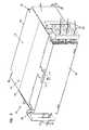
- FIG. 1is a front perspective view of one embodiment of an adapter panel arrangement, in accordance with the principles disclosed, shown with a drawer of the adapter panel arrangement in an open position;
- FIG. 2is a front perspective view of the adapter panel arrangement of FIG. 1 , shown with the drawer in a closed position;
- FIG. 3is a front perspective view of the adapter panel arrangement of FIG. 2 , shown with a cover of the arrangement closed;
- FIG. 4is a rear perspective view of the adapter panel arrangement of FIG. 1 ;
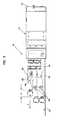
- FIG. 5is a side elevation view of the adapter panel arrangement of FIG. 4 ;
- FIG. 6is a top plan view of the adapter panel arrangement of FIG. 5 ;
- FIG. 7is a top perspective view of one embodiment of a sliding frame piece and an adapter array of the adapter panel arrangement of FIG. 1 , shown in isolation;
- FIG. 8is a side elevation view of the sliding frame piece and adapter array of FIG. 7 ;
- FIG. 9is a top plan view of the sliding frame piece and adapter array of FIG. 7 ;
- FIG. 10is a side elevation view of one embodiment of a guide of the adapter panel arrangement of FIG. 1 , shown in isolation;
- FIG. 11is a bottom perspective view of the guide of FIG. 10 ;
- FIG. 12is a top plan view of the guide of FIG. 10 , and a portion of the sliding frame piece of FIG. 9 ;
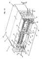
- FIG. 13is a front perspective view of the adapter panel arrangement of FIG. 2 , shown with an adapter array positioned in a forward position;
- FIG. 14is a side elevation view of the adapter panel arrangement of FIG. 13 ;
- FIG. 15is a top plan view of the adapter panel arrangement of FIG. 14 .
- FIG. 1illustrates a distribution frame or adapter panel arrangement 10 in accordance with the principles disclosed.
- the adapter panel arrangement 10is designed to provide a high density of cable terminations, yet facilitate access to the cable terminations from the rear during installation procedures, and from the front during post-installation procedures.
- the adapter panel arrangement 10 of the present disclosuregenerally includes a chassis 12 having an interior 14 .
- the interior 14is defined by a top wall 16 , a bottom wall 18 , a rear wall 20 , and side walls 22 , 24 .
- the adapter panel arrangement 10also includes a sliding drawer 34 that slides between an open position ( FIG. 1 ) and a closed position ( FIG. 2 ).
- a front cover 26is attached to the sliding drawer 34 . When the drawer 34 is in the closed position, the front cover 26 encloses the interior 14 of the chassis 12 when closed ( FIG. 3 ) and provides access to the interior 14 when open ( FIG. 2 ).
- the adapter panel arrangement 10includes a framework structure 30 ( FIG. 1 ) that is attached or mounted to the drawer 34 .
- a panel of adapters 32is mounted to the framework structure 30 .
- the drawer 34is designed to slide outward from the chassis 12 primarily for installation purposes. That is, the drawer 34 can be slid to the open position during installation or assembly of the adapter panel arrangement, but is position in the closed position ( FIG. 2 ) during operative use of the arrangement 10 .
- the framework structure 30 and the panel of adapters 32are located within the interior 14 of the chassis 12 and the drawer 34 is in the closed position ( FIG. 2 ).
- a useraccesses the panel of adapters 32 from a front opening 28 of the chassis 12 without sliding the drawer 34 forward.
- the panel of adapters 32includes a face panel 42 that defines a number of openings 44 (only one shown).
- Adapters 46are mounted within the openings 44 .
- the adaptersare LC type adapters; however, other types of adapters, such as SC, ST, FC and MPO type adapters can also be used in accordance with the principles disclosed.
- the adapters 46are blocked or grouped; each adapter block 58 including eight adapters 46 (four adapter pairs). Other number of adapters can be provided in an adapter block, such as four adapters (two adapter pairs), for example; the openings in the face panel 42 being correspondingly sized to receive the four-adapter blocks.
- single adapterscan be used and mounted with openings sized to receive the single adapters.
- the openings 44 of the face panel 42are arranged in rows; each row of mounted adapter blocks 58 defines an adapter array 48 .
- What is meant by a rowis that the openings 44 are arranged in a generally horizontal alignment, as opposed to being arranged in a column or in a vertical alignment; accordingly, the adapter arrays 48 are generally horizontal adapter arrays.
- the adapters 46 of the adapter blocks 58each includes a front connection end 50 ( FIG. 1 ) and a rear connection end 52 ( FIG. 4 ).
- the front connection ends 50 of the adapters 46are located toward the front opening 28 of the chassis 12
- the rear connection ends 52 of the adapters 46are located toward the rear wall 20 of the chassis 12 .
- the front connection ends 50 of the adapters 46define open frontward cable connection locations 54 ( FIG. 2 ) of the face panel 42
- the rear connection ends 52 of the adapters 46define open rearward cable connection locations 56 ( FIG. 4 ) of the face panel 42 .
- open cable connection locationsare locations that are provided in an open region in the chassis 12 , as opposed to a connection location that is enclosed within a housing or module, the housing or modules in turn being mounted within the chassis. That is, the panel of adapters 32 is a panel of unenclosed adapters 46 that are not enclosed relative to the other adapters 46 on the face panel 42 . While the panel of adapters itself is enclosed within the chassis 12 , the plurality of adapters 46 , and each of the adapter arrays 48 are not enclosed separately from the other adapters 46 or the other adapter arrays 48 .
- the adapter arrays 48 of the face panel 42are designed to slide in a lateral direction independent of other adapter arrays.
- the face panel 42is defined by a number of separate panel sections 60 .
- each separate panel sectiondefines one row of openings in which the blocks 58 of unenclosed adapters 46 are mounted, i.e., each panel section 60 contains one adapter array 48 .
- the panel sectionscan include, for example, two rows of openings that receive four-adapter blocks, for example; this panel section embodiment containing two adapter arrays.
- the face panel 42 of the adapter panel arrangement 10 illustratedincludes six panel sections 60 —two panel sections 60 positioned side-by-side, and stacked three panel sections high (see FIG. 1 ).
- Each panel section 60contains six blocks 58 having eight adapters 46 for a total of 288 frontward connection locations and rearward connection locations.
- Each separate panel section 60is designed to selectively slide in a forward, lateral direction (A) independent of the other panel sections.
- the forward, lateral direction (A)is a direction extending between the front opening 28 and the rear wall 20 , as opposed to a direction which is transverse to the bottom wall 18 of the chassis 12 , for example.
- each separate panel section 60 of the panel of adapters 32is attached to a sliding frame piece 62 .
- the sliding frame piece 62includes a pair of elongated rail members 64 .
- the elongated rail members 64include a forward rail portion 84 that extends forwardly from the panel section 60 , and a rearward rail portion 86 that extends rearwardly from the panel section 60 .
- the sliding frame piece 62can include a cross-support 88 to maintain the structural relationship of the rail members 64 .
- the pairs of elongated rail members 64are arranged to engage and slide within pairs of guides 66 (one shown in FIGS. 10-12 ) that are mounted to the framework structure 30 ( FIG. 1 ) of the arrangement 10 .
- the rail members 64 and the guides 66include a stop arrangement 68 that limits the sliding motion of the panel sections 60 between a rearward position (see the top panel section 60 in FIG. 5 ) and a forward position (see the bottom panel section 60 in FIG. 5 ).
- the stop arrangement 68( FIG. 12 ) is defined by at least one projection 70 ( FIGS. 10 and 11 ) located on each guide 66 of the pair of guides, and first and second pockets or detents 72 , 74 ( FIG. 9 ) formed in the rail members 64 .
- two projections 70(upper and lower projections) are provided on each of the guides 66 .
- upper and lower detents 72 , 74are formed in the rearward rail portions 86 of the rail members 64 .
- the detents 72 , 74formed in the rail members 64 and the projections 70 provided on the guides 66
- the detentscan be formed in the guides 66 and the projection correspondingly provided on the rail members 64 .
- the projections 70 of the guides 66seat within the first detents 72 of the rail members 64 to retain the panel section 60 in the rearward position.
- the guides 66are flexibly constructed so that when the panel section 60 is pulled forward, the projections 70 un-seat and slide along top and bottom surfaces 76 , 77 ( FIG. 8 ) of the rail members 64 .
- FIG. 12when the panel section 60 reaches the forward position, the projections 70 seat within the second detents 74 of the rail members 64 .
- This stop arrangement 68indicates to a user when the panel section 60 has reached the predetermined forward position, and similarly, the rearward position.
- the stop arrangement 68provides an indication of when the panel section 60 has moved a lateral distance D forward from the rearward position to the forward position.
- the lateral distance Dis no more than about 4.0 inches forward from the rearward position. In the illustrated embodiment, the lateral distance D is about 1.7 inches. Providing such an indication to the user prevents the user from moving the panel section 60 a distance beyond that which cables interconnected to the panel section 60 will allow.
- the present panel arrangement 10is designed such that the drawer 34 is intended to slide only during installation procedures, as opposed to post-installation or during operative use.
- cables 36such as fiber optic cables, are routed into the chassis 12 through rear openings 38 and terminated to the open rearward connection locations 56 of the face panel 42 (i.e., the rear connector ends 52 of the adapters 46 ).
- the fiber optic cables 36have a predetermined length that can be routed about cable storage spools or structures (see e.g., 78 , 80 in FIG. 1 ).
- the predetermined lengths of the cablesdo not have enough slack to accommodate drawer 34 movement during operative use, and the arrangement 10 does not have devices such as sliding radius limiters that take up or manage excessive movement of such cable slack.
- the predetermined lengths of the cablesgenerally accommodate only the limited sliding movement of the panel sections 60 . That is, while the drawer 34 may be slid out for purposes of installation, or for repairs requiring access to the region behind the panel of adapters 32 , the drawer 34 is not intended to slide for purposes of accessing the panel of adapters 32 during operative use of the adapter panel arrangement 10 . Operative use and access to the panel of adapters 32 is instead provided by the sliding movement of the panel sections 60 relative to the sliding movement of the drawer 34 .
- the lateral sliding movement of the panel sections 60provides access to the open cable connections (e.g., 54 , 56 ) defined by the adapter arrays 48 .
- Access to the open connection locations (e.g., 54 , 56 ) of the face panel 42is important in two primary instances: the first instance being during installation (e.g., during initial install or assembly, or during repair, replacement, or upgrade of the cable terminations at the rearward connection locations 56 of the panel 32 ); the second instance being after installation during operative use of the arrangement 10 .
- the drawer 34is pulled out to the open position.
- a technicianroutes the fiber optic cables 36 through the rear openings 38 of the chassis 12 and terminates the cables to the open rearward connection locations 56 of the panel of adapters 32 .
- one of the adapter arrays 48is positioned in the rearward position (e.g., the top array), while the remaining adapter arrays (e.g., the arrays located beneath the top array (see also FIGS. 5 and 6 )) are positioned in the forward position.
- the technicianhas better access to the open rearward connection locations 56 of the one panel section 60 positioned in the rearward position.
- the top wall 16 of the chassis 12includes removable access panels 92 .
- each of the panels 92slides outward in a direction B from the top wall 16 of the chassis 12 .
- the panels 92are shown engaged with the top wall 16 .
- each panel 92is locked in place by a flexible tab 94 that engages a hem or roll 98 formed in a top wall portion 100 of the top wall 16 .
- the flexible tab 94is defined by slots 96 formed in the panel 92 .
- the hem or roll 98is formed by bending or rolling a section of the top wall 16 over on itself; although structure can be attached to the top wall as an alternative to providing a hem.
- the flexible tab 94is flexed downward beyond the hem or roll 98 formed in the top wall portion 100 .
- the panelis then slid out in the direction shown in FIG. 2 and removed to define a top wall opening 104 (see e.g., FIG. 15 ) located adjacent to the front opening 28 of the chassis 12 .
- the top wall opening 104provides further access to the open rear connection locations 56 .
- the panel 92is place in relation to the top wall opening 104
- the flexible tab 94is flexed downward, and the panel 92 is then slid back into place.
- retaining flanges 102are formed in the top wall 16 at the top wall openings 104 . The retaining flanges 102 support the panels 92 when attached to the top wall 16 of the chassis 12 .
- the open rearward connection locations 56are typically access only during installation procedures, with the exception of repairs or upgrades, for example.
- the open frontward connection locations 54are accessed on a more regular basis to provide cross-connections between telecommunications equipment. Such use is referred to as operative use, or use that is post-installation and primarily involves maintaining or establishing cable terminations at the front connection ends 50 of the adapters 46 .
- the adapter panel arrangement 10is shown in operative use.
- the panel of adapters 32is accessed through the front opening 28 of the chassis 12 , with the drawer 34 positioned in the closed position.
- the cables 36 that enter the interior 14 of the chassis 12 through rear openings 38are terminated to the open rear connection locations 56 of the panel of adapters 32 .
- jumper cables or patching cables 40are also terminated to the panel of adapters 32 ; and in particular, to the open frontward connection locations 54 of the panel 32 .
- the patching cables 40provide the cross-connections between the adapter panel arrangement 10 and other telecommunications equipment (not shown).
- the patching cables 40are routed from the front opening 28 and through side openings 90 ( FIG. 3 ) of the chassis 12 to cable routing structure (e.g., channels, not shown) of the telecommunications system.
- each panel section 60 of the panel of adapters 32slides forward to separate the associated adapter array 48 from the other arrays.
- a techniciancan more easily grasp a particular connector of a patching cable 40 , and/or more easily terminate a patching cable to a particular adapter 46 of the forwardly-positioned array.
- the access panels 92 ( FIG. 13 ) of the top wall 16can be removed (as shown in FIG. 15 ) to provide even further access to the open frontward connection locations 54 of the panel sections.
- the forward rail portion 84 of the rail member 64can be used as a handle to pull the panel section 60 forward.
- the usercan slide the panel section 60 forward by grasping a retaining ring 82 attached to the rail member 64 of the sliding frame piece 62 .
- the retaining rings 82are attached to the ends of outer rail members 64 of the sliding frame piece 62 to protect the patching cables 40 from exceeding a minimum bend radius.
- the disclosed panel arrangementcan be adapted for use in other applications.
- copper cablesmay be used exclusively from fiber optic cables; and accordingly various types of wire terminations or wire connectors can be provided on the face panel of the arrangement.
- the face panel of the arrangementcan be provided with a combination of fiber optic and copper connectors and/or adapters.
- the present adapter panel arrangement 10provides a high-density adapter panel arrangement while facilitating access to otherwise crowded front and rear connection locations. Because of the access design of the present arrangement, the amount of space utilized on racks and cabinets is minimized; or, in the alternative, allows for expansion and upgrade of systems having spatial constraints, as more densely packed connection locations are provided without sacrificing effective access to the connection locations.
Landscapes
- Physics & Mathematics (AREA)
- Engineering & Computer Science (AREA)
- Computer Networks & Wireless Communication (AREA)
- General Physics & Mathematics (AREA)
- Optics & Photonics (AREA)
- Light Guides In General And Applications Therefor (AREA)
- Cable Accessories (AREA)
- Mechanical Coupling Of Light Guides (AREA)
Abstract
Description
Claims (20)
Priority Applications (1)
| Application Number | Priority Date | Filing Date | Title |
|---|---|---|---|
| US14/813,697US9435976B2 (en) | 2007-01-19 | 2015-07-30 | Adapter panel with lateral sliding adapter arrays |
Applications Claiming Priority (6)
| Application Number | Priority Date | Filing Date | Title |
|---|---|---|---|
| US11/655,760US7570860B2 (en) | 2007-01-19 | 2007-01-19 | Adapter panel with lateral sliding adapter arrays |
| US12/460,161US7873252B2 (en) | 2007-01-19 | 2009-07-13 | Adapter panel with lateral sliding adapter arrays |
| US12/930,783US8340490B2 (en) | 2007-01-19 | 2011-01-14 | Adapter panel with lateral sliding adapter arrays |
| US13/722,438US8953921B2 (en) | 2007-01-19 | 2012-12-20 | Adapter panel with lateral sliding adapter arrays |
| US14/617,249US9448378B2 (en) | 2007-01-19 | 2015-02-09 | Adapter panel with lateral sliding adapter arrays |
| US14/813,697US9435976B2 (en) | 2007-01-19 | 2015-07-30 | Adapter panel with lateral sliding adapter arrays |
Related Parent Applications (1)
| Application Number | Title | Priority Date | Filing Date |
|---|---|---|---|
| US14/617,249ContinuationUS9448378B2 (en) | 2007-01-19 | 2015-02-09 | Adapter panel with lateral sliding adapter arrays |
Publications (2)
| Publication Number | Publication Date |
|---|---|
| US20150331214A1 US20150331214A1 (en) | 2015-11-19 |
| US9435976B2true US9435976B2 (en) | 2016-09-06 |
Family
ID=39545060
Family Applications (20)
| Application Number | Title | Priority Date | Filing Date |
|---|---|---|---|
| US11/655,760ActiveUS7570860B2 (en) | 2007-01-19 | 2007-01-19 | Adapter panel with lateral sliding adapter arrays |
| US12/460,161ActiveUS7873252B2 (en) | 2007-01-19 | 2009-07-13 | Adapter panel with lateral sliding adapter arrays |
| US12/930,783Expired - Fee RelatedUS8340490B2 (en) | 2007-01-19 | 2011-01-14 | Adapter panel with lateral sliding adapter arrays |
| US13/722,438ActiveUS8953921B2 (en) | 2007-01-19 | 2012-12-20 | Adapter panel with lateral sliding adapter arrays |
| US14/617,249ActiveUS9448378B2 (en) | 2007-01-19 | 2015-02-09 | Adapter panel with lateral sliding adapter arrays |
| US14/813,697ActiveUS9435976B2 (en) | 2007-01-19 | 2015-07-30 | Adapter panel with lateral sliding adapter arrays |
| US14/813,740ActiveUS9488796B2 (en) | 2007-01-19 | 2015-07-30 | Adapter panel with lateral sliding adapter arrays |
| US14/813,737ActiveUS9448379B2 (en) | 2007-01-19 | 2015-07-30 | Adapter panel with lateral sliding adapter arrays |
| US14/813,765ActiveUS9435974B2 (en) | 2007-01-19 | 2015-07-30 | Adapter panel with lateral sliding adapter arrays |
| US14/813,806ActiveUS9638879B2 (en) | 2007-01-19 | 2015-07-30 | Adapter panel with lateral sliding adapter arrays |
| US15/332,869ActiveUS9690066B2 (en) | 2007-01-19 | 2016-10-24 | Adapter panel with lateral sliding adapter arrays |
| US15/499,608ActiveUS10310204B2 (en) | 2007-01-19 | 2017-04-27 | Adapter panel with lateral sliding adapter arrays |
| US15/631,956AbandonedUS20180039039A1 (en) | 2007-01-19 | 2017-06-23 | Adapter panel with lateral sliding adapter arrays |
| US16/427,963ActiveUS10739544B2 (en) | 2007-01-19 | 2019-05-31 | Adapter panel with lateral sliding adapter arrays |
| US16/841,233Active2027-02-21US11300747B2 (en) | 2007-01-19 | 2020-04-06 | Adapter panel with lateral sliding adapter arrays |
| US16/849,054Active2027-04-22US11333840B2 (en) | 2007-01-19 | 2020-04-15 | Adapter panel with lateral sliding adapter arrays |
| US16/849,731Active2027-05-26US11314028B2 (en) | 2007-01-19 | 2020-04-15 | Adapter panel with lateral sliding adapter arrays |
| US16/851,567Active2027-05-24US11262517B2 (en) | 2007-01-19 | 2020-04-17 | Adapter panel with lateral sliding adapter arrays |
| US17/730,680ActiveUS12111507B2 (en) | 2007-01-19 | 2022-04-27 | Adapter panel with lateral sliding adapter arrays |
| US18/789,976PendingUS20240385403A1 (en) | 2007-01-19 | 2024-07-31 | Adapter panel with lateral sliding adapter arrays |
Family Applications Before (5)
| Application Number | Title | Priority Date | Filing Date |
|---|---|---|---|
| US11/655,760ActiveUS7570860B2 (en) | 2007-01-19 | 2007-01-19 | Adapter panel with lateral sliding adapter arrays |
| US12/460,161ActiveUS7873252B2 (en) | 2007-01-19 | 2009-07-13 | Adapter panel with lateral sliding adapter arrays |
| US12/930,783Expired - Fee RelatedUS8340490B2 (en) | 2007-01-19 | 2011-01-14 | Adapter panel with lateral sliding adapter arrays |
| US13/722,438ActiveUS8953921B2 (en) | 2007-01-19 | 2012-12-20 | Adapter panel with lateral sliding adapter arrays |
| US14/617,249ActiveUS9448378B2 (en) | 2007-01-19 | 2015-02-09 | Adapter panel with lateral sliding adapter arrays |
Family Applications After (14)
| Application Number | Title | Priority Date | Filing Date |
|---|---|---|---|
| US14/813,740ActiveUS9488796B2 (en) | 2007-01-19 | 2015-07-30 | Adapter panel with lateral sliding adapter arrays |
| US14/813,737ActiveUS9448379B2 (en) | 2007-01-19 | 2015-07-30 | Adapter panel with lateral sliding adapter arrays |
| US14/813,765ActiveUS9435974B2 (en) | 2007-01-19 | 2015-07-30 | Adapter panel with lateral sliding adapter arrays |
| US14/813,806ActiveUS9638879B2 (en) | 2007-01-19 | 2015-07-30 | Adapter panel with lateral sliding adapter arrays |
| US15/332,869ActiveUS9690066B2 (en) | 2007-01-19 | 2016-10-24 | Adapter panel with lateral sliding adapter arrays |
| US15/499,608ActiveUS10310204B2 (en) | 2007-01-19 | 2017-04-27 | Adapter panel with lateral sliding adapter arrays |
| US15/631,956AbandonedUS20180039039A1 (en) | 2007-01-19 | 2017-06-23 | Adapter panel with lateral sliding adapter arrays |
| US16/427,963ActiveUS10739544B2 (en) | 2007-01-19 | 2019-05-31 | Adapter panel with lateral sliding adapter arrays |
| US16/841,233Active2027-02-21US11300747B2 (en) | 2007-01-19 | 2020-04-06 | Adapter panel with lateral sliding adapter arrays |
| US16/849,054Active2027-04-22US11333840B2 (en) | 2007-01-19 | 2020-04-15 | Adapter panel with lateral sliding adapter arrays |
| US16/849,731Active2027-05-26US11314028B2 (en) | 2007-01-19 | 2020-04-15 | Adapter panel with lateral sliding adapter arrays |
| US16/851,567Active2027-05-24US11262517B2 (en) | 2007-01-19 | 2020-04-17 | Adapter panel with lateral sliding adapter arrays |
| US17/730,680ActiveUS12111507B2 (en) | 2007-01-19 | 2022-04-27 | Adapter panel with lateral sliding adapter arrays |
| US18/789,976PendingUS20240385403A1 (en) | 2007-01-19 | 2024-07-31 | Adapter panel with lateral sliding adapter arrays |
Country Status (6)
| Country | Link |
|---|---|
| US (20) | US7570860B2 (en) |
| CN (2) | CN103281596B (en) |
| CA (2) | CA2944673C (en) |
| MX (1) | MX2009007633A (en) |
| TW (1) | TW200847802A (en) |
| WO (1) | WO2008089190A2 (en) |
Cited By (4)
| Publication number | Priority date | Publication date | Assignee | Title |
|---|---|---|---|---|
| US9638880B2 (en) | 2007-01-19 | 2017-05-02 | Commscope Technologies Llc | Adapter panel with lateral sliding adapter arrays |
| US9638879B2 (en) | 2007-01-19 | 2017-05-02 | Commscope Technologies Llc | Adapter panel with lateral sliding adapter arrays |
| US11009670B2 (en) | 2017-02-23 | 2021-05-18 | Commscope Technologies Llc | High fiber count termination device |
| US11567281B2 (en) | 2013-09-23 | 2023-01-31 | Commscope Connectivity Uk Limited | Telecommunications chassis |
Families Citing this family (120)
| Publication number | Priority date | Publication date | Assignee | Title |
|---|---|---|---|---|
| WO2008029291A2 (en)* | 2006-06-23 | 2008-03-13 | Adc Gmbh | Slide and tilt mechanism for a telecommunications panel |
| US7509016B2 (en)* | 2007-03-09 | 2009-03-24 | Adc Telecommunications, Inc. | Telecommunication rack unit tray |
| US8179684B2 (en)* | 2007-10-29 | 2012-05-15 | Adc Telecommunications, Inc. | Sliding adapter panel with living hinge and forward/rearward locking |
| US8184938B2 (en)* | 2008-08-29 | 2012-05-22 | Corning Cable Systems Llc | Rear-installable fiber optic modules and equipment |
| US7945135B2 (en)* | 2008-08-29 | 2011-05-17 | Corning Cable Systems Llc | Telescoping fiber optic module and related equipment |
| US8452148B2 (en)* | 2008-08-29 | 2013-05-28 | Corning Cable Systems Llc | Independently translatable modules and fiber optic equipment trays in fiber optic equipment |
| US11294136B2 (en) | 2008-08-29 | 2022-04-05 | Corning Optical Communications LLC | High density and bandwidth fiber optic apparatuses and related equipment and methods |
| US7856166B2 (en) | 2008-09-02 | 2010-12-21 | Corning Cable Systems Llc | High-density patch-panel assemblies for optical fiber telecommunications |
| US8290330B2 (en)* | 2008-09-05 | 2012-10-16 | Adc Gmbh | Patch panel assembly |
| US7697811B2 (en)* | 2008-09-08 | 2010-04-13 | Ortronics, Inc. | Horizontal fiber optic patching assembly |
| DE102009004917B3 (en)* | 2009-01-16 | 2010-07-22 | Hans Moll | Patch panel and procedures for its installation |
| WO2010088604A1 (en)* | 2009-02-02 | 2010-08-05 | Adc Telecommunications, Inc. | Multi-fiber cable management panel |
| EP2221932B1 (en) | 2009-02-24 | 2011-11-16 | CCS Technology Inc. | Holding device for a cable or an assembly for use with a cable |
| US8270798B2 (en)* | 2009-02-27 | 2012-09-18 | Corning Cable Systems Llc | Routing guide for a movable fiber optic equipment tray or module |
| AU2009200824A1 (en)* | 2009-03-03 | 2010-09-23 | Tyco Electronics Services Gmbh | Consolidation point enclosure |
| US8897637B2 (en) | 2009-04-22 | 2014-11-25 | Adc Gmbh | Method and arrangement for identifying at least one object |
| US8699838B2 (en) | 2009-05-14 | 2014-04-15 | Ccs Technology, Inc. | Fiber optic furcation module |
| US8538226B2 (en) | 2009-05-21 | 2013-09-17 | Corning Cable Systems Llc | Fiber optic equipment guides and rails configured with stopping position(s), and related equipment and methods |
| JP5706399B2 (en)* | 2009-05-21 | 2015-04-22 | コーニング ケーブル システムズ リミテッド ライアビリティ カンパニー | Fiber optic equipment supporting movable fiber optic equipment trays and modules, related equipment and methods |
| US9075216B2 (en) | 2009-05-21 | 2015-07-07 | Corning Cable Systems Llc | Fiber optic housings configured to accommodate fiber optic modules/cassettes and fiber optic panels, and related components and methods |
| EP2433165B1 (en)* | 2009-05-21 | 2016-12-21 | Corning Optical Communications LLC | Fiber optic equipment with guides and rails configured with stopping positions |
| WO2010148325A1 (en) | 2009-06-19 | 2010-12-23 | Corning Cable Systems Llc | High fiber optic cable packing density apparatus |
| US8712206B2 (en) | 2009-06-19 | 2014-04-29 | Corning Cable Systems Llc | High-density fiber optic modules and module housings and related equipment |
| EP2443497B1 (en) | 2009-06-19 | 2020-03-04 | Corning Cable Systems LLC | High density and bandwidth fiber optic apparatus |
| US8714368B2 (en)* | 2009-09-09 | 2014-05-06 | Adc Telecommunications, Inc. | Pass-through trough |
| WO2011047288A1 (en) | 2009-10-16 | 2011-04-21 | Adc Telecommunications, Inc. | Managed connectivity in fiber optic systems and methods thereof |
| US8625950B2 (en) | 2009-12-18 | 2014-01-07 | Corning Cable Systems Llc | Rotary locking apparatus for fiber optic equipment trays and related methods |
| US8992099B2 (en) | 2010-02-04 | 2015-03-31 | Corning Cable Systems Llc | Optical interface cards, assemblies, and related methods, suited for installation and use in antenna system equipment |
| WO2011100613A1 (en) | 2010-02-12 | 2011-08-18 | Adc Telecommunications, Inc. | Communications bladed system |
| US8913866B2 (en) | 2010-03-26 | 2014-12-16 | Corning Cable Systems Llc | Movable adapter panel |
| RU2012140925A (en)* | 2010-04-09 | 2014-05-20 | 3М Инновейтив Пропертиз Компани | HIGH DENSITY FIBER OPTICAL DISTRIBUTION SYSTEM |
| CA2796221C (en) | 2010-04-16 | 2018-02-13 | Ccs Technology, Inc. | Sealing and strain relief device for data cables |
| EP2381284B1 (en) | 2010-04-23 | 2014-12-31 | CCS Technology Inc. | Under floor fiber optic distribution device |
| US8705926B2 (en) | 2010-04-30 | 2014-04-22 | Corning Optical Communications LLC | Fiber optic housings having a removable top, and related components and methods |
| US9720195B2 (en) | 2010-04-30 | 2017-08-01 | Corning Optical Communications LLC | Apparatuses and related components and methods for attachment and release of fiber optic housings to and from an equipment rack |
| US8660397B2 (en) | 2010-04-30 | 2014-02-25 | Corning Cable Systems Llc | Multi-layer module |
| US9632270B2 (en) | 2010-04-30 | 2017-04-25 | Corning Optical Communications LLC | Fiber optic housings configured for tool-less assembly, and related components and methods |
| US9075217B2 (en) | 2010-04-30 | 2015-07-07 | Corning Cable Systems Llc | Apparatuses and related components and methods for expanding capacity of fiber optic housings |
| US8879881B2 (en) | 2010-04-30 | 2014-11-04 | Corning Cable Systems Llc | Rotatable routing guide and assembly |
| US9519118B2 (en) | 2010-04-30 | 2016-12-13 | Corning Optical Communications LLC | Removable fiber management sections for fiber optic housings, and related components and methods |
| US9377597B2 (en)* | 2010-06-02 | 2016-06-28 | Commscope Technologies Llc | Aggregator for a switch rack system |
| US11251608B2 (en) | 2010-07-13 | 2022-02-15 | Raycap S.A. | Overvoltage protection system for wireless communication systems |
| US8718436B2 (en) | 2010-08-30 | 2014-05-06 | Corning Cable Systems Llc | Methods, apparatuses for providing secure fiber optic connections |
| US9279951B2 (en) | 2010-10-27 | 2016-03-08 | Corning Cable Systems Llc | Fiber optic module for limited space applications having a partially sealed module sub-assembly |
| US8662760B2 (en) | 2010-10-29 | 2014-03-04 | Corning Cable Systems Llc | Fiber optic connector employing optical fiber guide member |
| US9116324B2 (en) | 2010-10-29 | 2015-08-25 | Corning Cable Systems Llc | Stacked fiber optic modules and fiber optic equipment configured to support stacked fiber optic modules |
| CA2819235C (en) | 2010-11-30 | 2018-01-16 | Corning Cable Systems Llc | Fiber device holder and strain relief device |
| WO2012106510A2 (en) | 2011-02-02 | 2012-08-09 | Corning Cable Systems Llc | Dense fiber optic connector assemblies and related connectors and cables suitable for establishing optical connections for optical backplanes in equipment racks |
| US9008485B2 (en) | 2011-05-09 | 2015-04-14 | Corning Cable Systems Llc | Attachment mechanisms employed to attach a rear housing section to a fiber optic housing, and related assemblies and methods |
| AU2012275598A1 (en) | 2011-06-30 | 2014-01-16 | Corning Optical Communications LLC | Fiber optic equipment assemblies employing non-U-width-sized housings and related methods |
| US8953924B2 (en) | 2011-09-02 | 2015-02-10 | Corning Cable Systems Llc | Removable strain relief brackets for securing fiber optic cables and/or optical fibers to fiber optic equipment, and related assemblies and methods |
| CN103975264B (en) | 2011-10-07 | 2015-09-16 | Adc电信公司 | Slidable fiber optic connection module with cable slack management |
| US9038832B2 (en) | 2011-11-30 | 2015-05-26 | Corning Cable Systems Llc | Adapter panel support assembly |
| US9217832B2 (en) | 2012-01-06 | 2015-12-22 | Hewlett Packard Enterprise Development Lp | Connector modules having optical connectors moveable between a retracted position and an extended position |
| US9250409B2 (en) | 2012-07-02 | 2016-02-02 | Corning Cable Systems Llc | Fiber-optic-module trays and drawers for fiber-optic equipment |
| US9042702B2 (en) | 2012-09-18 | 2015-05-26 | Corning Cable Systems Llc | Platforms and systems for fiber optic cable attachment |
| US10082636B2 (en) | 2012-09-21 | 2018-09-25 | Commscope Technologies Llc | Slidable fiber optic connection module with cable slack management |
| ES2551077T3 (en) | 2012-10-26 | 2015-11-16 | Ccs Technology, Inc. | Fiber optic management unit and fiber optic distribution device |
| CN105074525A (en) | 2013-01-29 | 2015-11-18 | 泰科电子瑞侃有限公司 | Fiber Distribution System |
| US9128262B2 (en) | 2013-02-05 | 2015-09-08 | Adc Telecommunications, Inc. | Slidable telecommunications tray with cable slack management |
| US8985862B2 (en) | 2013-02-28 | 2015-03-24 | Corning Cable Systems Llc | High-density multi-fiber adapter housings |
| US9423579B2 (en)* | 2013-03-05 | 2016-08-23 | Finisar Corporation | Latch mechanism for communication module |
| EP2989496B1 (en) | 2013-04-24 | 2019-06-12 | CommScope Connectivity Belgium BVBA | Universal mounting mechanism for mounting a telecommunications chassis to a telecommunications fixture |
| AP2015008820A0 (en) | 2013-04-24 | 2015-10-31 | Adc Czech Republic Sro | Optical fiber distribution system |
| US9268103B2 (en)* | 2013-05-10 | 2016-02-23 | Senko Advanced Components, Inc. | Interlockable fiber optic connector adaptors |
| CN105393152B (en)* | 2013-05-20 | 2019-05-07 | Adc电信股份有限公司 | Outlet structure of cable routing system |
| US9494758B2 (en) | 2014-04-03 | 2016-11-15 | Commscope Technologies Llc | Fiber optic distribution system |
| US9470868B2 (en) | 2014-04-28 | 2016-10-18 | Telect, Inc. | Ultra-high density frames |
| US9426926B2 (en)* | 2014-05-21 | 2016-08-23 | Enginuity Communications Corporation | Secure flat wall mounting rack |
| US9632271B2 (en)* | 2014-06-17 | 2017-04-25 | Ortronics, Inc. | Modularly mountable cable management systems and associated methods |
| CN106575024B (en)* | 2014-06-23 | 2019-07-09 | Adc电信公司 | Undercarriage system with blades |
| WO2016012295A1 (en) | 2014-07-22 | 2016-01-28 | Tyco Electronics Raychem Bvba | Door hinge mechanism for telecommunicatons panel |
| EP3192274A4 (en) | 2014-09-11 | 2018-05-16 | ADC Telecommunications, Inc. | Door hinge mechanism for telecommunications panel |
| US9885845B2 (en)* | 2015-01-15 | 2018-02-06 | Commscope, Inc. Of North Carolina | Module and assembly for fiber optic interconnections |
| US9516781B2 (en)* | 2015-02-19 | 2016-12-06 | All Systems Broadband, Inc. | Fiber optic shelf with a removable roof panel |
| AU2016239875C1 (en) | 2015-04-03 | 2021-06-24 | CommScope Connectivity Belgium BVBA | Telecommunications distribution elements |
| EP3329346A4 (en) | 2015-07-29 | 2019-06-12 | Commscope Technologies LLC | CHASSIS SYSTEMS FOR BLADE SERVERS |
| US10802237B2 (en)* | 2015-11-03 | 2020-10-13 | Raycap S.A. | Fiber optic cable management system |
| CN105323998A (en)* | 2015-11-10 | 2016-02-10 | 南京普天天纪楼宇智能有限公司 | Jumper-connection-free copper cable distributing frame for 19-inch machine cabinet |
| US9829666B2 (en)* | 2016-02-17 | 2017-11-28 | Telect, Inc. | Ultra-high density patch systems |
| WO2017184501A1 (en) | 2016-04-19 | 2017-10-26 | Commscope, Inc. Of North Carolina | Door assembly for a telecommunications chassis with a combination hinge structure |
| ES2851948T3 (en) | 2016-04-19 | 2021-09-09 | Commscope Inc North Carolina | Telecom rack with slide out trays |
| WO2018057615A1 (en)* | 2016-09-21 | 2018-03-29 | Commscope Technologies Llc | Adapter block assembly |
| US11099344B2 (en)* | 2016-11-08 | 2021-08-24 | Telect, Inc. | Fiber cassette |
| WO2018136812A1 (en) | 2017-01-20 | 2018-07-26 | Raycap S.A. | Power transmission system for wireless communication systems |
| US10291969B2 (en)* | 2017-02-14 | 2019-05-14 | Go!Foton Holdings, Inc. | Rear cable management |
| EP3404461B1 (en)* | 2017-05-16 | 2022-06-29 | Reichle & De-Massari AG | Cable management device |
| WO2018226959A1 (en) | 2017-06-07 | 2018-12-13 | Commscope Technologies Llc | Fiber optic adapter and cassette |
| US11385429B2 (en) | 2017-10-18 | 2022-07-12 | Commscope Technologies Llc | Fiber optic connection cassette |
| CN107728274B (en)* | 2017-11-14 | 2020-12-18 | 深圳市讯禾实业有限公司 | Multifunctional optical fiber distribution box for communication equipment |
| US11852882B2 (en) | 2018-02-28 | 2023-12-26 | Commscope Technologies Llc | Packaging assembly for telecommunications equipment |
| US10416406B1 (en) | 2018-03-01 | 2019-09-17 | Afl Telecommunications Llc | Communications module housing |
| WO2019204317A1 (en) | 2018-04-16 | 2019-10-24 | Commscope Technologies Llc | Adapter structure |
| US11635578B2 (en) | 2018-04-17 | 2023-04-25 | CommScope Connectivity Belgium BVBA | Telecommunications distribution elements |
| US10971928B2 (en) | 2018-08-28 | 2021-04-06 | Raycap Ip Assets Ltd | Integrated overvoltage protection and monitoring system |
| EP3844547A1 (en) | 2018-08-31 | 2021-07-07 | CommScope Connectivity Belgium BVBA | Frame assemblies for optical fiber distribution elements |
| EP3844546A1 (en) | 2018-08-31 | 2021-07-07 | CommScope Connectivity Belgium BVBA | Frame assemblies for optical fiber distribution elements |
| WO2020043914A1 (en) | 2018-08-31 | 2020-03-05 | CommScope Connectivity Belgium BVBA | Frame assemblies for optical fiber distribution elements |
| EP3845044B1 (en) | 2018-08-31 | 2023-02-15 | CommScope Connectivity Belgium BVBA | Frame assemblies for optical fiber distribution elements |
| PL3844973T3 (en) | 2018-08-31 | 2025-03-03 | CommScope Connectivity Belgium BVBA | Frame assemblies for optical fiber distribution elements |
| WO2020084012A1 (en) | 2018-10-23 | 2020-04-30 | CommScope Connectivity Belgium BVBA | Frame assemblies for optical fiber distribution elements |
| US10451828B1 (en) | 2018-11-09 | 2019-10-22 | Afl Telecommunications Llc | Communications module housing |
| US12078859B2 (en) | 2019-01-14 | 2024-09-03 | Commscope Technologies Llc | Equipment panel with termination region |
| EP3914947A1 (en) | 2019-01-25 | 2021-12-01 | CommScope Connectivity Belgium BVBA | Frame assemblies for optical fiber distribution elements |
| US11677164B2 (en) | 2019-09-25 | 2023-06-13 | Raycap Ip Assets Ltd | Hybrid antenna distribution unit |
| US11036020B2 (en) | 2019-10-10 | 2021-06-15 | Telect, Inc. | Outside plant data communication systems |
| WO2021148544A1 (en) | 2020-01-22 | 2021-07-29 | CommScope Connectivity Belgium BVBA | Cable termination units for optical fiber distribution elements |
| US12099246B2 (en) | 2020-01-24 | 2024-09-24 | CommScope Connectivity Belgium BVBA | Telecommunications distribution elements |
| US11169345B1 (en) | 2020-05-11 | 2021-11-09 | Google Llc | Sliding tray for fiber optic panel assembly |
| EP3971622A1 (en) | 2020-07-02 | 2022-03-23 | Go!Foton Holdings, Inc. | Intelligent optical switch |
| US11947178B2 (en) | 2020-09-17 | 2024-04-02 | Panduit Corp. | Optical distribution and splice frame including cassettes |
| CN113534375B (en)* | 2021-06-26 | 2022-11-11 | 华为技术有限公司 | Optical fiber distribution equipment and optical fiber dispatching system |
| US11716821B1 (en) | 2021-07-21 | 2023-08-01 | The United States Of America As Represented By The Secretary Of The Navy | Compact stackable trays with positioning racks |
| US12237134B2 (en) | 2021-12-28 | 2025-02-25 | Raycap Ip Assets Ltd | Circuit protection for hybrid antenna distribution units |
| US12323270B2 (en)* | 2022-02-14 | 2025-06-03 | Ciena Corporation | Cabling topology for expansion |
| US12216319B2 (en) | 2022-02-15 | 2025-02-04 | Google Llc | Easily accessible fiber optic panel assembly |
| US20230384529A1 (en)* | 2022-05-26 | 2023-11-30 | Google Llc | Slidable Fiber Optic Adaptor in Optic Fiber Panel Assembly |
| US20240126035A1 (en)* | 2022-10-17 | 2024-04-18 | viaPhoton, Inc. | High density fiber panel organization |
| US12133351B2 (en)* | 2022-10-26 | 2024-10-29 | Dell Products L.P. | Cable management system for a server rack |
| AU2024209154A1 (en)* | 2023-01-20 | 2025-07-10 | Commscope Technologies Llc | Fiber channel enabling high speed installation |
Citations (33)
| Publication number | Priority date | Publication date | Assignee | Title |
|---|---|---|---|---|
| US4765710A (en) | 1985-07-30 | 1988-08-23 | Siemens Aktiengesellschaft | Distributing frame for optical waveguides and the like |
| EP0341027A2 (en) | 1988-05-02 | 1989-11-08 | Gte Control Devices Of Puerto Rico Incorporated | Fiber distribution panel |
| US5129030A (en) | 1991-05-30 | 1992-07-07 | At&T Bell Laboratories | Movable lightguide connector panel |
| US5167001A (en) | 1991-09-03 | 1992-11-24 | Northern Telecom Limited | Optical fiber storage and connector tray and shelf and tray assembly |
| US5497444A (en) | 1994-01-21 | 1996-03-05 | Adc Telecommunications, Inc. | High-density fiber distribution frame |
| US5758003A (en) | 1996-03-15 | 1998-05-26 | Adc Telecommunications, Inc. | High density fiber management |
| US5778131A (en)* | 1993-09-29 | 1998-07-07 | Pirelli General Plc | Assembly for use in connecting optical fibres including a manifold device |
| US6195493B1 (en) | 1999-05-21 | 2001-02-27 | Scientific-Atlanta, Inc. | Universal chassis for CATV headends or telecommunications company central office for optical electronic equipment |
| US6385381B1 (en) | 1999-09-21 | 2002-05-07 | Lucent Technologies Inc. | Fiber optic interconnection combination closure |
| US6504988B1 (en) | 2000-01-24 | 2003-01-07 | Adc Telecommunications, Inc. | Cable management panel with sliding drawer |
| US6591051B2 (en) | 2001-11-16 | 2003-07-08 | Adc Telecommunications, Inc. | Fiber termination block with angled slide |
| US20030174996A1 (en) | 2002-03-15 | 2003-09-18 | Fiber Optic Network Solutions, Inc. | Optical fiber enclosure system using integrated optical connector and coupler assembly |
| US20030223723A1 (en) | 2002-05-28 | 2003-12-04 | Massey Gaines N. | Reconfigurable fiber optic cable management enclosure |
| US6715619B2 (en) | 2002-07-22 | 2004-04-06 | Adc Telecommunications, Inc. | Fiber management drawer and patch panel |
| US20040086252A1 (en) | 2002-11-05 | 2004-05-06 | Smith Trevor D. | Fiber panel with integrated couplers |
| US6752665B2 (en) | 2002-11-18 | 2004-06-22 | Trompeter Electronics, Inc. | Modular cross-connect with removable switch assembly |
| US6760531B1 (en) | 1999-03-01 | 2004-07-06 | Adc Telecommunications, Inc. | Optical fiber distribution frame with outside plant enclosure |
| US6920274B2 (en)* | 2003-12-23 | 2005-07-19 | Adc Telecommunications, Inc. | High density optical fiber distribution frame with modules |
| US6937807B2 (en) | 2002-04-24 | 2005-08-30 | Adc Telecommunications, Inc. | Cable management panel with sliding drawer |
| US6944383B1 (en) | 2004-04-12 | 2005-09-13 | Adc Telecommunications, Inc. | Cable management panel with sliding drawer and methods |
| EP1603345A2 (en) | 2004-06-01 | 2005-12-07 | Commscope Solutions Properties, LLC | Modular communications shelf system and methods for using the same |
| US7194181B2 (en) | 2005-03-31 | 2007-03-20 | Adc Telecommunications, Inc. | Adapter block including connector storage |
| US7200316B2 (en) | 2003-11-26 | 2007-04-03 | Corning Cable Systems Llc | Connector housing for a communication network |
| US7257223B2 (en) | 2001-05-10 | 2007-08-14 | Adc Telecommunications, Inc. | Splitter assembly for a telecommunications system |
| US7273320B2 (en) | 2001-07-31 | 2007-09-25 | Pluris, Inc. | Method and apparatus for cleaning particulate matter from an optic-connector surface |
| US7318751B2 (en) | 2005-01-13 | 2008-01-15 | Tyco Electronics Corporation | Die-cast adapter |
| US7376322B2 (en) | 2004-11-03 | 2008-05-20 | Adc Telecommunications, Inc. | Fiber optic module and system including rear connectors |
| US7474828B2 (en) | 2006-10-02 | 2009-01-06 | Emerson Network Power, Energy Systems, North America, Inc. | Slack limiting fiber management system for an optic fiber distribution hub |
| US20090129033A1 (en) | 2007-10-29 | 2009-05-21 | Mark Smrha | Sliding adapter panel with living hinge and forward/rearward locking |
| US7570861B2 (en) | 2007-01-19 | 2009-08-04 | Adc Telecommunications, Inc. | Adapter panel with lateral sliding adapter arrays |
| US7570860B2 (en) | 2007-01-19 | 2009-08-04 | Adc Telecommunications, Inc. | Adapter panel with lateral sliding adapter arrays |
| US20110267794A1 (en) | 2010-02-12 | 2011-11-03 | Chad Anderson | Communications bladed panel systems |
| US8991950B2 (en) | 2013-07-10 | 2015-03-31 | Exablox Corporation | Modular electronics chassis |
Family Cites Families (45)
| Publication number | Priority date | Publication date | Assignee | Title |
|---|---|---|---|---|
| EP0530325B1 (en) | 1990-05-21 | 1997-03-05 | Minnesota Mining And Manufacturing Company | Optical fiber distribution center |
| US5613030A (en) | 1995-05-15 | 1997-03-18 | The Whitaker Corporation | High density fiber optic interconnection enclosure |
| CN2323405Y (en)* | 1997-12-24 | 1999-06-09 | 大原武芳 | Drawer counter body with adjustable connection sliding rail |
| JP2002082230A (en) | 2000-09-08 | 2002-03-22 | Nissho Musen Co Ltd | Cassette having optical fiber cable connecting adapter in termination box |
| US6560114B2 (en) | 2001-06-29 | 2003-05-06 | Intel Corporation | Rack-mounted server and associated methods |
| US6627812B2 (en) | 2001-08-24 | 2003-09-30 | Sun Microsystems, Inc. | Apparatus for containing electro-magnetic interference |
| US6854894B1 (en) | 2001-08-30 | 2005-02-15 | Bryan Yunker | Optical receptacle, transceiver and cage |
| US6935866B2 (en)* | 2002-04-02 | 2005-08-30 | Adc Telecommunications, Inc. | Card edge coaxial connector |
| DE10219892A1 (en) | 2002-05-03 | 2004-02-05 | Krone Gmbh | Coupling for fiber optic connectors |
| US6715928B1 (en)* | 2003-02-27 | 2004-04-06 | Molex Incorporated | Connector panel mount system |
| US6988747B2 (en)* | 2003-03-20 | 2006-01-24 | Rain Bird Corporation | Multi-diameter tube coupling |
| US7171099B2 (en) | 2003-07-31 | 2007-01-30 | Adc Telecommunications, Inc. | Slide arrangement for cable drawer |
| CN2671002Y (en)* | 2003-12-08 | 2005-01-12 | 大众电脑股份有限公司 | The main casing of the drawer computer |
| US7218828B2 (en) | 2005-01-24 | 2007-05-15 | Feustel Clay A | Optical fiber power splitter module apparatus |
| US7094095B1 (en) | 2005-02-25 | 2006-08-22 | Panduit Corp. | Stair-stepped angled patch panel |
| KR100699907B1 (en) | 2005-04-25 | 2007-03-27 | 주식회사 케이티엔티 | Optical distribution box for high speed information and communication building |
| US7625250B2 (en) | 2005-05-23 | 2009-12-01 | Blackwell Donald A | Interlocking modules for high packing ratios |
| US7460758B2 (en) | 2005-06-03 | 2008-12-02 | Telect Inc. | Fiber management system |
| US20060274515A1 (en)* | 2005-06-04 | 2006-12-07 | Tellabs San Jose, Inc. | Methods and apparatus for a configurable chassis |
| US7636507B2 (en) | 2005-06-17 | 2009-12-22 | Adc Telecommunications, Inc. | Compact blind mateable optical splitter |
| US7509015B2 (en) | 2006-07-26 | 2009-03-24 | Ortronics, Inc. | Secure fiber optic network cassette assembly |
| US20080037209A1 (en) | 2006-08-11 | 2008-02-14 | Open Source Systems, Inc. | Computer chassis for two motherboards oriented one above the other |
| US7409137B2 (en) | 2006-10-04 | 2008-08-05 | Adc Telecommunications, Inc. | Slide arrangement for cable drawer |
| US7689089B2 (en) | 2006-10-11 | 2010-03-30 | Panduit Corp. | Release latch for pre-terminated cassette |
| US7493002B2 (en) | 2007-01-19 | 2009-02-17 | Adc Telecommunications, Inc. | Fiber optic adapter cassette and panel |
| US7590328B2 (en)* | 2007-08-02 | 2009-09-15 | Adc Telecommunications, Inc. | Fiber termination block with splitters |
| US7542649B1 (en) | 2008-02-27 | 2009-06-02 | Ofs Fitel Llc | Optical fiber line card assembly |
| EP2277071A2 (en) | 2008-04-21 | 2011-01-26 | ADC Telecommunications, Inc. | Fiber optic splice tray |
| CN101583256A (en) | 2008-05-12 | 2009-11-18 | 爱德龙通讯系统(上海)有限公司 | Cable management panel |
| US7756380B2 (en) | 2008-07-31 | 2010-07-13 | Commscope, Inc. Of North Carolina | Hinged cable guide panel providing access to panel rear |
| US8452148B2 (en)* | 2008-08-29 | 2013-05-28 | Corning Cable Systems Llc | Independently translatable modules and fiber optic equipment trays in fiber optic equipment |
| US8538226B2 (en)* | 2009-05-21 | 2013-09-17 | Corning Cable Systems Llc | Fiber optic equipment guides and rails configured with stopping position(s), and related equipment and methods |
| US8625950B2 (en) | 2009-12-18 | 2014-01-07 | Corning Cable Systems Llc | Rotary locking apparatus for fiber optic equipment trays and related methods |
| WO2011100634A2 (en) | 2010-02-12 | 2011-08-18 | Adc Telecommunications, Inc. | Managed fiber connectivity systems |
| US8879881B2 (en) | 2010-04-30 | 2014-11-04 | Corning Cable Systems Llc | Rotatable routing guide and assembly |
| CN110174737A (en) | 2010-06-23 | 2019-08-27 | Adc电信公司 | Telecommunication assembly |
| CN103975264B (en) | 2011-10-07 | 2015-09-16 | Adc电信公司 | Slidable fiber optic connection module with cable slack management |
| US9075203B2 (en) | 2012-01-17 | 2015-07-07 | Adc Telecommunications, Inc. | Fiber optic adapter block |
| US20130308916A1 (en)* | 2012-05-16 | 2013-11-21 | Scott Eaker Buff | High-density port tap fiber optic modules, and related systems and methods for monitoring optical networks |
| US9223094B2 (en) | 2012-10-05 | 2015-12-29 | Tyco Electronics Nederland Bv | Flexible optical circuit, cassettes, and methods |
| ES2719271T3 (en)* | 2013-03-19 | 2019-07-09 | Adc Czech Republic Sro | Control of curvature and support of connection cables, mobile, for telecommunications panels |
| US10203465B2 (en)* | 2014-04-25 | 2019-02-12 | Commscope Technologies Llc | Managed connectivity in cable spool assemblies |
| US9661787B2 (en) | 2015-06-29 | 2017-05-23 | Telefonaktiebolaget Lm Ericsson (Publ) | Facilitating front access to rear-mounted assembly in equipment chassis |
| EP3329346A4 (en)* | 2015-07-29 | 2019-06-12 | Commscope Technologies LLC | CHASSIS SYSTEMS FOR BLADE SERVERS |
| US10302885B2 (en)* | 2016-11-04 | 2019-05-28 | Corning Optical Communications LLC | Fiber terminal rack mount with front-to-back fiber routing management |
- 2007
- 2007-01-19USUS11/655,760patent/US7570860B2/enactiveActive
- 2008
- 2008-01-15WOPCT/US2008/051080patent/WO2008089190A2/enactiveApplication Filing
- 2008-01-15CACA2944673Apatent/CA2944673C/enactiveActive
- 2008-01-15CNCN201310110427.2Apatent/CN103281596B/enactiveActive
- 2008-01-15CACA2675791Apatent/CA2675791C/enactiveActive
- 2008-01-15CNCN2008800053232Apatent/CN101617541B/enactiveActive
- 2008-01-15MXMX2009007633Apatent/MX2009007633A/enactiveIP Right Grant
- 2008-01-18TWTW097102051Apatent/TW200847802A/enunknown
- 2009
- 2009-07-13USUS12/460,161patent/US7873252B2/enactiveActive
- 2011
- 2011-01-14USUS12/930,783patent/US8340490B2/ennot_activeExpired - Fee Related
- 2012
- 2012-12-20USUS13/722,438patent/US8953921B2/enactiveActive
- 2015
- 2015-02-09USUS14/617,249patent/US9448378B2/enactiveActive
- 2015-07-30USUS14/813,697patent/US9435976B2/enactiveActive
- 2015-07-30USUS14/813,740patent/US9488796B2/enactiveActive
- 2015-07-30USUS14/813,737patent/US9448379B2/enactiveActive
- 2015-07-30USUS14/813,765patent/US9435974B2/enactiveActive
- 2015-07-30USUS14/813,806patent/US9638879B2/enactiveActive
- 2016
- 2016-10-24USUS15/332,869patent/US9690066B2/enactiveActive
- 2017
- 2017-04-27USUS15/499,608patent/US10310204B2/enactiveActive
- 2017-06-23USUS15/631,956patent/US20180039039A1/ennot_activeAbandoned
- 2019
- 2019-05-31USUS16/427,963patent/US10739544B2/enactiveActive
- 2020
- 2020-04-06USUS16/841,233patent/US11300747B2/enactiveActive
- 2020-04-15USUS16/849,054patent/US11333840B2/enactiveActive
- 2020-04-15USUS16/849,731patent/US11314028B2/enactiveActive
- 2020-04-17USUS16/851,567patent/US11262517B2/enactiveActive
- 2022
- 2022-04-27USUS17/730,680patent/US12111507B2/enactiveActive
- 2024
- 2024-07-31USUS18/789,976patent/US20240385403A1/enactivePending
Patent Citations (53)
| Publication number | Priority date | Publication date | Assignee | Title |
|---|---|---|---|---|
| US4765710A (en) | 1985-07-30 | 1988-08-23 | Siemens Aktiengesellschaft | Distributing frame for optical waveguides and the like |
| EP0341027A2 (en) | 1988-05-02 | 1989-11-08 | Gte Control Devices Of Puerto Rico Incorporated | Fiber distribution panel |
| US5129030A (en) | 1991-05-30 | 1992-07-07 | At&T Bell Laboratories | Movable lightguide connector panel |
| US5167001A (en) | 1991-09-03 | 1992-11-24 | Northern Telecom Limited | Optical fiber storage and connector tray and shelf and tray assembly |
| US5778131A (en)* | 1993-09-29 | 1998-07-07 | Pirelli General Plc | Assembly for use in connecting optical fibres including a manifold device |
| US5497444A (en) | 1994-01-21 | 1996-03-05 | Adc Telecommunications, Inc. | High-density fiber distribution frame |
| US5717810A (en) | 1994-01-21 | 1998-02-10 | Adc Telecommunications, Inc. | High-density fiber distribution frame |
| US5758003A (en) | 1996-03-15 | 1998-05-26 | Adc Telecommunications, Inc. | High density fiber management |
| US6760531B1 (en) | 1999-03-01 | 2004-07-06 | Adc Telecommunications, Inc. | Optical fiber distribution frame with outside plant enclosure |
| US6195493B1 (en) | 1999-05-21 | 2001-02-27 | Scientific-Atlanta, Inc. | Universal chassis for CATV headends or telecommunications company central office for optical electronic equipment |
| US6385381B1 (en) | 1999-09-21 | 2002-05-07 | Lucent Technologies Inc. | Fiber optic interconnection combination closure |
| US6504988B1 (en) | 2000-01-24 | 2003-01-07 | Adc Telecommunications, Inc. | Cable management panel with sliding drawer |
| US7257223B2 (en) | 2001-05-10 | 2007-08-14 | Adc Telecommunications, Inc. | Splitter assembly for a telecommunications system |
| US7273320B2 (en) | 2001-07-31 | 2007-09-25 | Pluris, Inc. | Method and apparatus for cleaning particulate matter from an optic-connector surface |
| US6591051B2 (en) | 2001-11-16 | 2003-07-08 | Adc Telecommunications, Inc. | Fiber termination block with angled slide |
| US20030174996A1 (en) | 2002-03-15 | 2003-09-18 | Fiber Optic Network Solutions, Inc. | Optical fiber enclosure system using integrated optical connector and coupler assembly |
| US6937807B2 (en) | 2002-04-24 | 2005-08-30 | Adc Telecommunications, Inc. | Cable management panel with sliding drawer |
| US20030223723A1 (en) | 2002-05-28 | 2003-12-04 | Massey Gaines N. | Reconfigurable fiber optic cable management enclosure |
| US6715619B2 (en) | 2002-07-22 | 2004-04-06 | Adc Telecommunications, Inc. | Fiber management drawer and patch panel |
| US6804447B2 (en) | 2002-11-05 | 2004-10-12 | Adc Telecommunications, Inc. | Fiber panel with integrated couplers |
| US20040086252A1 (en) | 2002-11-05 | 2004-05-06 | Smith Trevor D. | Fiber panel with integrated couplers |
| US6752665B2 (en) | 2002-11-18 | 2004-06-22 | Trompeter Electronics, Inc. | Modular cross-connect with removable switch assembly |
| US7200316B2 (en) | 2003-11-26 | 2007-04-03 | Corning Cable Systems Llc | Connector housing for a communication network |
| US6920274B2 (en)* | 2003-12-23 | 2005-07-19 | Adc Telecommunications, Inc. | High density optical fiber distribution frame with modules |
| US6944383B1 (en) | 2004-04-12 | 2005-09-13 | Adc Telecommunications, Inc. | Cable management panel with sliding drawer and methods |
| EP1603345A2 (en) | 2004-06-01 | 2005-12-07 | Commscope Solutions Properties, LLC | Modular communications shelf system and methods for using the same |
| US7376322B2 (en) | 2004-11-03 | 2008-05-20 | Adc Telecommunications, Inc. | Fiber optic module and system including rear connectors |
| US7318751B2 (en) | 2005-01-13 | 2008-01-15 | Tyco Electronics Corporation | Die-cast adapter |
| US7194181B2 (en) | 2005-03-31 | 2007-03-20 | Adc Telecommunications, Inc. | Adapter block including connector storage |
| US7474828B2 (en) | 2006-10-02 | 2009-01-06 | Emerson Network Power, Energy Systems, North America, Inc. | Slack limiting fiber management system for an optic fiber distribution hub |
| US7873252B2 (en) | 2007-01-19 | 2011-01-18 | Adc Telecommunications, Inc. | Adapter panel with lateral sliding adapter arrays |
| US8867884B2 (en) | 2007-01-19 | 2014-10-21 | Adc Telecommunications, Inc. | Adapter panel with lateral sliding adapter arrays |
| US7570860B2 (en) | 2007-01-19 | 2009-08-04 | Adc Telecommunications, Inc. | Adapter panel with lateral sliding adapter arrays |
| US7873253B2 (en) | 2007-01-19 | 2011-01-18 | Adc Telecommunications, Inc. | Adapter panel with lateral sliding adapter arrays |
| US20150338594A1 (en) | 2007-01-19 | 2015-11-26 | Adc Telecommunications, Inc. | Adapter panel with lateral sliding adapter arrays |
| US20150338598A1 (en) | 2007-01-19 | 2015-11-26 | Adc Telecommunication, Inc. | Adapter panel with lateral sliding adapter arrays |
| US7570861B2 (en) | 2007-01-19 | 2009-08-04 | Adc Telecommunications, Inc. | Adapter panel with lateral sliding adapter arrays |
| US8340490B2 (en) | 2007-01-19 | 2012-12-25 | Adc Telecommunications, Inc. | Adapter panel with lateral sliding adapter arrays |
| US8346044B2 (en) | 2007-01-19 | 2013-01-01 | Adc Telecommunications, Inc. | Adapter panel with lateral sliding adapter arrays |
| US20150338597A1 (en) | 2007-01-19 | 2015-11-26 | Adc Telecommunications, Inc. | Adapter panel with lateral sliding adapter arrays |
| US8953921B2 (en) | 2007-01-19 | 2015-02-10 | Adc Telecommunications, Inc. | Adapter panel with lateral sliding adapter arrays |
| US20150338599A1 (en) | 2007-01-19 | 2015-11-26 | Adc Telecommunications, Inc. | Adapter panel with lateral sliding adapter arrays |
| US20150131958A1 (en) | 2007-01-19 | 2015-05-14 | Adc Telecommunications, Inc. | Adapter panel with lateral sliding adapter arrays |
| US9097871B2 (en) | 2007-01-19 | 2015-08-04 | Adc Telecommunications, Inc. | Adapter panel with lateral sliding adapter arrays |
| US20150286021A1 (en) | 2007-01-19 | 2015-10-08 | Adc Telecommunications, Inc. | Adapter panel with lateral sliding adapter arrays |
| US20150331216A1 (en) | 2007-01-19 | 2015-11-19 | Adc Telecommunications, Inc. | Adapter panel with lateral sliding adapter arrays |
| US20150331215A1 (en) | 2007-01-19 | 2015-11-19 | Adc Telecommunications, Inc. | Adapter panel with lateral sliding adapter arrays |
| US20150338593A1 (en) | 2007-01-19 | 2015-11-26 | Adc Telecommunication, Inc. | Adapter panel with lateral sliding adapter arrays |
| US20150338595A1 (en) | 2007-01-19 | 2015-11-26 | Adc Telecommunications, Inc. | Adapter panel with lateral sliding adapter arrays |
| US8179684B2 (en) | 2007-10-29 | 2012-05-15 | Adc Telecommunications, Inc. | Sliding adapter panel with living hinge and forward/rearward locking |
| US20090129033A1 (en) | 2007-10-29 | 2009-05-21 | Mark Smrha | Sliding adapter panel with living hinge and forward/rearward locking |
| US20110267794A1 (en) | 2010-02-12 | 2011-11-03 | Chad Anderson | Communications bladed panel systems |
| US8991950B2 (en) | 2013-07-10 | 2015-03-31 | Exablox Corporation | Modular electronics chassis |
Non-Patent Citations (5)
| Title |
|---|
| ADC Telecommunications Fiber Outside Plant Systems, 4 pgs.; Aug. 1998. |
| ADC Telecommunications Fiber Panel Products, Second Edition, 6 pgs.; Jul. 1996. |
| Corning Cable Systems; "Jumper Routing Procedure for Enhanced Management Frame"; Issue 2; dated Apr. 2002; 4 pgs. |
| Drawing of ADC Telecommunications Drawer, 1 page; Aug. 2006. |
| Drawing of ADC Telecommunications Drawer, 2 pages, Nov. 2006. |
Cited By (22)
| Publication number | Priority date | Publication date | Assignee | Title |
|---|---|---|---|---|
| US10969553B2 (en) | 2007-01-19 | 2021-04-06 | Commscope Technologies Llc | Adapter panel with lateral sliding adapter arrays |
| US11333840B2 (en) | 2007-01-19 | 2022-05-17 | Commscope Technologies Llc | Adapter panel with lateral sliding adapter arrays |
| US9645342B2 (en) | 2007-01-19 | 2017-05-09 | Commscope Technologies Llc | Adapter panel with lateral sliding adapter arrays |
| US9703059B2 (en) | 2007-01-19 | 2017-07-11 | Commscope Technologies Llc | Adapter panel with lateral sliding adapter arrays |
| US9709764B2 (en) | 2007-01-19 | 2017-07-18 | Commscope Technologies Llc | Adapter panel with lateral sliding adapter arrays |
| US9995897B2 (en) | 2007-01-19 | 2018-06-12 | Commscope Technologies Llc | Adapter panel with lateral sliding adapter arrays |
| US10203464B1 (en) | 2007-01-19 | 2019-02-12 | Commscope Technologies Llc | Adapter panel with lateral sliding adapter arrays |
| US10310204B2 (en) | 2007-01-19 | 2019-06-04 | Commscope Technologies Llc | Adapter panel with lateral sliding adapter arrays |
| US10473874B2 (en) | 2007-01-19 | 2019-11-12 | Commscope Technologies Llc | Adapter panel with lateral sliding adapter arrays |
| US11262517B2 (en) | 2007-01-19 | 2022-03-01 | Commscope Technologies Llc | Adapter panel with lateral sliding adapter arrays |
| US9638879B2 (en) | 2007-01-19 | 2017-05-02 | Commscope Technologies Llc | Adapter panel with lateral sliding adapter arrays |
| US12164168B2 (en) | 2007-01-19 | 2024-12-10 | Commscope Technologies Llc | Adapter panel with lateral sliding adapter arrays |
| US10739544B2 (en) | 2007-01-19 | 2020-08-11 | Commscope Technologies Llc | Adapter panel with lateral sliding adapter arrays |
| US11269150B2 (en) | 2007-01-19 | 2022-03-08 | Commscope Technologies Llc | Adapter panel with lateral sliding adapter arrays |
| US11300747B2 (en) | 2007-01-19 | 2022-04-12 | Commscope Technologies Llc | Adapter panel with lateral sliding adapter arrays |
| US11314028B2 (en) | 2007-01-19 | 2022-04-26 | Commscope Technologies Llc | Adapter panel with lateral sliding adapter arrays |
| US9638880B2 (en) | 2007-01-19 | 2017-05-02 | Commscope Technologies Llc | Adapter panel with lateral sliding adapter arrays |
| US12111507B2 (en) | 2007-01-19 | 2024-10-08 | Commscope Technologies Llc | Adapter panel with lateral sliding adapter arrays |
| US11789225B2 (en) | 2007-01-19 | 2023-10-17 | Commscope Technologies Llc | Adapter panel with lateral sliding adapter arrays |
| US12025846B2 (en) | 2013-09-23 | 2024-07-02 | Commscope Connectivity Uk Limited | Telecommunications chassis |
| US11567281B2 (en) | 2013-09-23 | 2023-01-31 | Commscope Connectivity Uk Limited | Telecommunications chassis |
| US11009670B2 (en) | 2017-02-23 | 2021-05-18 | Commscope Technologies Llc | High fiber count termination device |
Also Published As
Similar Documents
| Publication | Publication Date | Title |
|---|---|---|
| US12111507B2 (en) | Adapter panel with lateral sliding adapter arrays | |
| US11269150B2 (en) | Adapter panel with lateral sliding adapter arrays |
Legal Events
| Date | Code | Title | Description |
|---|---|---|---|
| AS | Assignment | Owner name:ADC TELECOMMUNICATIONS, INC., MINNESOTA Free format text:ASSIGNMENT OF ASSIGNORS INTEREST;ASSIGNORS:SMRHA, MARK;COBURN, HUTCH;SJODIN, CHAD;REEL/FRAME:036351/0504 Effective date:20070403 | |
| AS | Assignment | Owner name:TYCO ELECTRONICS SERVICES GMBH, SWITZERLAND Free format text:ASSIGNMENT OF ASSIGNORS INTEREST;ASSIGNOR:ADC TELECOMMUNICATIONS, INC.;REEL/FRAME:036392/0460 Effective date:20110930 | |
| AS | Assignment | Owner name:COMMSCOPE EMEA LIMITED, IRELAND Free format text:ASSIGNMENT OF ASSIGNORS INTEREST;ASSIGNOR:TYCO ELECTRONICS SERVICES GMBH;REEL/FRAME:036956/0001 Effective date:20150828 | |
| AS | Assignment | Owner name:COMMSCOPE TECHNOLOGIES LLC, NORTH CAROLINA Free format text:ASSIGNMENT OF ASSIGNORS INTEREST;ASSIGNOR:COMMSCOPE EMEA LIMITED;REEL/FRAME:037012/0001 Effective date:20150828 | |
| AS | Assignment | Owner name:JPMORGAN CHASE BANK, N.A., AS COLLATERAL AGENT, ILLINOIS Free format text:PATENT SECURITY AGREEMENT (TERM);ASSIGNOR:COMMSCOPE TECHNOLOGIES LLC;REEL/FRAME:037513/0709 Effective date:20151220 Owner name:JPMORGAN CHASE BANK, N.A., AS COLLATERAL AGENT, ILLINOIS Free format text:PATENT SECURITY AGREEMENT (ABL);ASSIGNOR:COMMSCOPE TECHNOLOGIES LLC;REEL/FRAME:037514/0196 Effective date:20151220 Owner name:JPMORGAN CHASE BANK, N.A., AS COLLATERAL AGENT, IL Free format text:PATENT SECURITY AGREEMENT (TERM);ASSIGNOR:COMMSCOPE TECHNOLOGIES LLC;REEL/FRAME:037513/0709 Effective date:20151220 Owner name:JPMORGAN CHASE BANK, N.A., AS COLLATERAL AGENT, IL Free format text:PATENT SECURITY AGREEMENT (ABL);ASSIGNOR:COMMSCOPE TECHNOLOGIES LLC;REEL/FRAME:037514/0196 Effective date:20151220 | |
| STCF | Information on status: patent grant | Free format text:PATENTED CASE | |
| AS | Assignment | Owner name:REDWOOD SYSTEMS, INC., NORTH CAROLINA Free format text:RELEASE BY SECURED PARTY;ASSIGNOR:JPMORGAN CHASE BANK, N.A.;REEL/FRAME:048840/0001 Effective date:20190404 Owner name:COMMSCOPE TECHNOLOGIES LLC, NORTH CAROLINA Free format text:RELEASE BY SECURED PARTY;ASSIGNOR:JPMORGAN CHASE BANK, N.A.;REEL/FRAME:048840/0001 Effective date:20190404 Owner name:COMMSCOPE, INC. OF NORTH CAROLINA, NORTH CAROLINA Free format text:RELEASE BY SECURED PARTY;ASSIGNOR:JPMORGAN CHASE BANK, N.A.;REEL/FRAME:048840/0001 Effective date:20190404 Owner name:ANDREW LLC, NORTH CAROLINA Free format text:RELEASE BY SECURED PARTY;ASSIGNOR:JPMORGAN CHASE BANK, N.A.;REEL/FRAME:048840/0001 Effective date:20190404 Owner name:ALLEN TELECOM LLC, ILLINOIS Free format text:RELEASE BY SECURED PARTY;ASSIGNOR:JPMORGAN CHASE BANK, N.A.;REEL/FRAME:048840/0001 Effective date:20190404 Owner name:ALLEN TELECOM LLC, ILLINOIS Free format text:RELEASE BY SECURED PARTY;ASSIGNOR:JPMORGAN CHASE BANK, N.A.;REEL/FRAME:049260/0001 Effective date:20190404 Owner name:COMMSCOPE TECHNOLOGIES LLC, NORTH CAROLINA Free format text:RELEASE BY SECURED PARTY;ASSIGNOR:JPMORGAN CHASE BANK, N.A.;REEL/FRAME:049260/0001 Effective date:20190404 Owner name:COMMSCOPE, INC. OF NORTH CAROLINA, NORTH CAROLINA Free format text:RELEASE BY SECURED PARTY;ASSIGNOR:JPMORGAN CHASE BANK, N.A.;REEL/FRAME:049260/0001 Effective date:20190404 Owner name:ANDREW LLC, NORTH CAROLINA Free format text:RELEASE BY SECURED PARTY;ASSIGNOR:JPMORGAN CHASE BANK, N.A.;REEL/FRAME:049260/0001 Effective date:20190404 Owner name:REDWOOD SYSTEMS, INC., NORTH CAROLINA Free format text:RELEASE BY SECURED PARTY;ASSIGNOR:JPMORGAN CHASE BANK, N.A.;REEL/FRAME:049260/0001 Effective date:20190404 | |
| AS | Assignment | Owner name:WILMINGTON TRUST, NATIONAL ASSOCIATION, AS COLLATE Free format text:PATENT SECURITY AGREEMENT;ASSIGNOR:COMMSCOPE TECHNOLOGIES LLC;REEL/FRAME:049892/0051 Effective date:20190404 Owner name:JPMORGAN CHASE BANK, N.A., NEW YORK Free format text:TERM LOAN SECURITY AGREEMENT;ASSIGNORS:COMMSCOPE, INC. OF NORTH CAROLINA;COMMSCOPE TECHNOLOGIES LLC;ARRIS ENTERPRISES LLC;AND OTHERS;REEL/FRAME:049905/0504 Effective date:20190404 Owner name:JPMORGAN CHASE BANK, N.A., NEW YORK Free format text:ABL SECURITY AGREEMENT;ASSIGNORS:COMMSCOPE, INC. OF NORTH CAROLINA;COMMSCOPE TECHNOLOGIES LLC;ARRIS ENTERPRISES LLC;AND OTHERS;REEL/FRAME:049892/0396 Effective date:20190404 Owner name:WILMINGTON TRUST, NATIONAL ASSOCIATION, AS COLLATERAL AGENT, CONNECTICUT Free format text:PATENT SECURITY AGREEMENT;ASSIGNOR:COMMSCOPE TECHNOLOGIES LLC;REEL/FRAME:049892/0051 Effective date:20190404 | |
| MAFP | Maintenance fee payment | Free format text:PAYMENT OF MAINTENANCE FEE, 4TH YEAR, LARGE ENTITY (ORIGINAL EVENT CODE: M1551); ENTITY STATUS OF PATENT OWNER: LARGE ENTITY Year of fee payment:4 | |
| AS | Assignment | Owner name:WILMINGTON TRUST, DELAWARE Free format text:SECURITY INTEREST;ASSIGNORS:ARRIS SOLUTIONS, INC.;ARRIS ENTERPRISES LLC;COMMSCOPE TECHNOLOGIES LLC;AND OTHERS;REEL/FRAME:060752/0001 Effective date:20211115 | |
| MAFP | Maintenance fee payment | Free format text:PAYMENT OF MAINTENANCE FEE, 8TH YEAR, LARGE ENTITY (ORIGINAL EVENT CODE: M1552); ENTITY STATUS OF PATENT OWNER: LARGE ENTITY Year of fee payment:8 | |
| AS | Assignment | Owner name:APOLLO ADMINISTRATIVE AGENCY LLC, NEW YORK Free format text:SECURITY INTEREST;ASSIGNORS:ARRIS ENTERPRISES LLC;COMMSCOPE TECHNOLOGIES LLC;COMMSCOPE INC., OF NORTH CAROLINA;AND OTHERS;REEL/FRAME:069889/0114 Effective date:20241217 | |
| AS | Assignment | Owner name:RUCKUS WIRELESS, LLC (F/K/A RUCKUS WIRELESS, INC.), NORTH CAROLINA Free format text:RELEASE OF SECURITY INTEREST AT REEL/FRAME 049905/0504;ASSIGNOR:JPMORGAN CHASE BANK, N.A., AS COLLATERAL AGENT;REEL/FRAME:071477/0255 Effective date:20241217 Owner name:COMMSCOPE TECHNOLOGIES LLC, NORTH CAROLINA Free format text:RELEASE OF SECURITY INTEREST AT REEL/FRAME 049905/0504;ASSIGNOR:JPMORGAN CHASE BANK, N.A., AS COLLATERAL AGENT;REEL/FRAME:071477/0255 Effective date:20241217 Owner name:COMMSCOPE, INC. OF NORTH CAROLINA, NORTH CAROLINA Free format text:RELEASE OF SECURITY INTEREST AT REEL/FRAME 049905/0504;ASSIGNOR:JPMORGAN CHASE BANK, N.A., AS COLLATERAL AGENT;REEL/FRAME:071477/0255 Effective date:20241217 Owner name:ARRIS SOLUTIONS, INC., NORTH CAROLINA Free format text:RELEASE OF SECURITY INTEREST AT REEL/FRAME 049905/0504;ASSIGNOR:JPMORGAN CHASE BANK, N.A., AS COLLATERAL AGENT;REEL/FRAME:071477/0255 Effective date:20241217 Owner name:ARRIS TECHNOLOGY, INC., NORTH CAROLINA Free format text:RELEASE OF SECURITY INTEREST AT REEL/FRAME 049905/0504;ASSIGNOR:JPMORGAN CHASE BANK, N.A., AS COLLATERAL AGENT;REEL/FRAME:071477/0255 Effective date:20241217 Owner name:ARRIS ENTERPRISES LLC (F/K/A ARRIS ENTERPRISES, INC.), NORTH CAROLINA Free format text:RELEASE OF SECURITY INTEREST AT REEL/FRAME 049905/0504;ASSIGNOR:JPMORGAN CHASE BANK, N.A., AS COLLATERAL AGENT;REEL/FRAME:071477/0255 Effective date:20241217 |