US9435891B2 - Time of flight camera with stripe illumination - Google Patents
Time of flight camera with stripe illuminationDownload PDFInfo
- Publication number
- US9435891B2 US9435891B2US13/767,953US201313767953AUS9435891B2US 9435891 B2US9435891 B2US 9435891B2US 201313767953 AUS201313767953 AUS 201313767953AUS 9435891 B2US9435891 B2US 9435891B2
- Authority
- US
- United States
- Prior art keywords
- view
- field
- camera
- pixels
- light
- Prior art date
- Legal status (The legal status is an assumption and is not a legal conclusion. Google has not performed a legal analysis and makes no representation as to the accuracy of the status listed.)
- Active
Links
- 238000005286illuminationMethods0.000titleclaimsabstractdescription66
- 238000003384imaging methodMethods0.000claimsabstractdescription30
- 238000000034methodMethods0.000claimsabstractdescription19
- 230000003287optical effectEffects0.000claimsdescription14
- 230000001360synchronised effectEffects0.000claimsdescription7
- 238000004364calculation methodMethods0.000claimsdescription3
- 230000010354integrationEffects0.000description8
- 238000013459approachMethods0.000description6
- 238000005259measurementMethods0.000description6
- 238000010586diagramMethods0.000description5
- 230000008901benefitEffects0.000description4
- 238000005070samplingMethods0.000description3
- 108091006146ChannelsProteins0.000description2
- 238000006073displacement reactionMethods0.000description2
- 101150066718FMOD geneProteins0.000description1
- 241000282485Vulpes vulpesSpecies0.000description1
- 230000004913activationEffects0.000description1
- 238000010276constructionMethods0.000description1
- 238000012937correctionMethods0.000description1
- 238000013461designMethods0.000description1
- 238000001514detection methodMethods0.000description1
- 239000011159matrix materialSubstances0.000description1
- 238000000691measurement methodMethods0.000description1
- 238000012634optical imagingMethods0.000description1
- 238000003909pattern recognitionMethods0.000description1
- 230000010363phase shiftEffects0.000description1
- 238000000926separation methodMethods0.000description1
- 238000007493shaping processMethods0.000description1
Images


Classifications
- G—PHYSICS
- G01—MEASURING; TESTING
- G01S—RADIO DIRECTION-FINDING; RADIO NAVIGATION; DETERMINING DISTANCE OR VELOCITY BY USE OF RADIO WAVES; LOCATING OR PRESENCE-DETECTING BY USE OF THE REFLECTION OR RERADIATION OF RADIO WAVES; ANALOGOUS ARRANGEMENTS USING OTHER WAVES
- G01S17/00—Systems using the reflection or reradiation of electromagnetic waves other than radio waves, e.g. lidar systems
- G01S17/88—Lidar systems specially adapted for specific applications
- G01S17/89—Lidar systems specially adapted for specific applications for mapping or imaging
- G—PHYSICS
- G01—MEASURING; TESTING
- G01S—RADIO DIRECTION-FINDING; RADIO NAVIGATION; DETERMINING DISTANCE OR VELOCITY BY USE OF RADIO WAVES; LOCATING OR PRESENCE-DETECTING BY USE OF THE REFLECTION OR RERADIATION OF RADIO WAVES; ANALOGOUS ARRANGEMENTS USING OTHER WAVES
- G01S17/00—Systems using the reflection or reradiation of electromagnetic waves other than radio waves, e.g. lidar systems
- G01S17/02—Systems using the reflection of electromagnetic waves other than radio waves
- G01S17/06—Systems determining position data of a target
- G01S17/08—Systems determining position data of a target for measuring distance only
- G01S17/32—Systems determining position data of a target for measuring distance only using transmission of continuous waves, whether amplitude-, frequency-, or phase-modulated, or unmodulated
- G01S17/36—Systems determining position data of a target for measuring distance only using transmission of continuous waves, whether amplitude-, frequency-, or phase-modulated, or unmodulated with phase comparison between the received signal and the contemporaneously transmitted signal
- G—PHYSICS
- G01—MEASURING; TESTING
- G01S—RADIO DIRECTION-FINDING; RADIO NAVIGATION; DETERMINING DISTANCE OR VELOCITY BY USE OF RADIO WAVES; LOCATING OR PRESENCE-DETECTING BY USE OF THE REFLECTION OR RERADIATION OF RADIO WAVES; ANALOGOUS ARRANGEMENTS USING OTHER WAVES
- G01S17/00—Systems using the reflection or reradiation of electromagnetic waves other than radio waves, e.g. lidar systems
- G01S17/88—Lidar systems specially adapted for specific applications
- G01S17/89—Lidar systems specially adapted for specific applications for mapping or imaging
- G01S17/894—3D imaging with simultaneous measurement of time-of-flight at a 2D array of receiver pixels, e.g. time-of-flight cameras or flash lidar
Definitions
- TOFThree dimensional (3D) time-of-flight
- TOF systemsare based on the phase-measurement technique of emitted intensity-modulated light, which is reflected by the scene. The reflected light is imaged onto a sensor. The photo-generated electrons are demodulated in the sensor. Based on the phase information, the distance for each pixel is deduced.
- Oggier, et al.in “An all-solid-state optical range camera for 3D real-time imaging with sub-centimeter depth resolution (SwissRanger)”, Proc. Of the SPIE, Vol. 5249, pp. 534-545, 2004.
- All TOF camerasinclude an illumination module, an imaging sensor and some optics.
- the illumination moduleis designed such as to illuminate the scene so as to enable its capture as uniformly as possible, or adjust the illumination based on the scene of interest.
- All existing full field TOF camerasilluminate the pixels of interest simultaneously with an illumination module that comprises either an array of light emitting diodes (LEDs) or laser diodes.
- the illumination moduleis designed with the intention to keep the required dynamic range of the sensor as small as possible, often leading to adjustments that result in the reflection of the same amount of light back to the camera from all objects within the field of interest.
- the illuminationis built to illuminate the field-of-view as uniformly as possible.
- Optimal illumination beam shaping for TOF camerasare presented by Oggier et al. in “Time of Flight Camera with Rectangular Field of Illumination”, U.S. Pat. Appl. Publ. No. US 2011/0025843 A1. Further improvements can be achieved using masked illumination as suggested by Oggier et al. in “3D TOF camera with masked illumination”, U.S. patent application Ser. No. 13/196,291, filed on Aug. 2, 2011. Other approaches using diffractive optical elements or other refractive devices are possible to improve the illumination.
- the present inventionconcerns a TOF based camera system with an illumination module that illuminates only a given region of the field of view of the imaging sensor. This translates to a region of the pixels of the imaging sensor.
- the acquired data of the pixel regionis processed and/or readout, typically.
- a second pixel regionis illuminated and the second pixel region is processed. This procedure can be repeated a couple of times up to a few hundred even thousand times until the entire pixel array is readout and possibly readout a number of times.
- the full depth imageis then reconstructed based on the results from the different pixel region acquisitions.
- the different pixel regionsare preferably one or several lines or columns of pixels.
- the illumination generated by the illumination moduletherefore has preferably a vertical or horizontal stripe-shape characteristics, although other shapes such as squares or rectangles are possible.
- the different regionsare preferably adjacent to each other, but might also overlap each other.
- the pixel regions or portions of the field of view that are illuminatedare preferably a small part of the total pixels/total field of view of the sensor, such as 10% or less.
- the results of the different pixel regionsare combined to build together the full 3D depth map of the entire scene captured by the entire pixel field of the imaging sensor.
- the pixels on the image sensorare preferably reset after each pixel region acquisition.
- Illuminating and measuring pixel region by pixel regionindependently has advantages with respect to multiple reflections (multi-path) since the pixel region receives more direct light while indirect paths or any multiple reflections are reduced.
- a pixel region measurementis shorter in time than a full field measurement. This is due to shorter readout and acquisition time. For this reason, the so-called motion artifacts are reduced compared with conventional cameras.
- the inventionfeatures a time of flight camera comprising an imaging sensor that demodulates received light from a field of view of a scene and an illumination module for illuminating portions of the field of view of the scene with modulated light.
- the illuminated portionsare scanned over the field of view, preferably sequentially.
- the imaging sensorreads out pixels that correspond to the illuminated portions of the field of view.
- the illuminated portionsare horizontal stripes that are successively scanned over the entire field of view.
- the illumination modulecomprises a light source and a scanning device for scanning the light from the light source over the field of view.
- the scanning of the scanning deviceis synchronized to the acquisition by the imaging sensor.
- the inventionfeatures a method of operation for a time of flight camera.
- the methodcomprises demodulating received light from a field of view of a scene and illuminating portions of the field of view of the scene with the modulated light.
- FIG. 1schematically illustrates a TOF camera system.
- FIGS. 2A and 2Bare plots, as a function of time, of the emitted signal or illumination light ES and received signal or light impinging on the imaging sensor RS and the demodulation of the received signal RS.
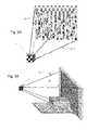
- FIGS. 3A and 3Bare schematic diagrams illustrating rear and side views showing conventional illumination that covers the entire field of view of the imaging sensor of the camera.
- FIGS. 4A-4Eare schematic side view diagrams illustrating the sequential illumination of the field of view of the imaging sensor by the illumination module according to the present invention.
- FIG. 5is a timing diagram of the different samples and the corresponding pixel region according to an embodiment of the invention.
- FIG. 6is a schematic diagram illustrating one embodiment of the illumination module.
- FIG. 7is a plot of the scanning of the illumination light by external control where a slow movement during the illumination of a certain pixel region is synchronized with the object speed to reduce motion-induced artifacts due to the object movement.
- FIGS. 8A, 8B, and 8Cschematically show a front view, camera cross section through the lens, and camera cross section through the illumination module, shown for the case of a horizontal stripe system arrangement.
- FIG. 1illustrates the operation of a TOF camera system 5 .
- Modulated emitted illumination light 11 from an illumination module 20is sent to the object 30 of a scene. A fraction of the total optical power sent out is reflected 12 back to the camera 5 , through optics 40 and detected by the 3D imaging sensor 90 .
- the sensor 90comprises a two dimensional pixel matrix of the demodulation pixels 100 . Each pixel 100 is capable of demodulating the impinging light signal 10 that is collected by the lens 40 and imaged on the imaging sensor 90 .
- An electronics control unit 60controls the timing of the illumination module 20 and sensor 90 to enable its synchronous detection.
- the demodulation valuesallow for each pixel to compute the time-of-flight, which, in turn, directly corresponds to the distance information R of the corresponding point in the scene 30 .
- the two-dimension gray scale image with the distance informationis converted into a three-dimensional image at the data output interface 70 that comprises image processor for example. This can be displayed to a user via display D or used as a machine vision input.
- the time-of-flight TOFis obtained by demodulating the light signal 11 that is reflected from the scene 30 and impinges on each pixel 100 of the sensor 90 .
- Different modulation schemesare known, for example pseudo-noise modulation, pulse modulation or continuous modulation. The latter technique is used in the following, without restricting the invention to this particular modulation scheme, in order to explain the invention in more detail.
- fmodis the modulation frequency of the optical signal.
- Typical state-of-the-art modulation frequenciesrange from a few MHz up to a few hundreds of MHz or even GHz.
- FIGS. 2A and Bshow examples for the emitted and reflected optical signals when continuous sinusoidal modulation is applied, and for the sampling process of the detected signal, respectively.
- FIG. 2Ashows both the modulated emitted illumination signal ES 11 and received impinging signal RS 10 .
- the amplitude A, offset B of the received signal RS and phase P between both signalsare unknown, but they can be unambiguously reconstructed with at least three samples of the received signal.
- BGrepresents the received signal part due to background light.
- FIG. 2Ba sampling with four samples per modulation period is depicted.
- Each sampleis an integration of the electrical photo-signal over a duration dt that is a predefined fraction of the modulation period.
- dtcorresponds to a quarter of the period.
- the photo-generated chargesmay be accumulated over several—up to more than 1 million—modulation periods in the integration nodes.
- the electronic control unit 60employing for example a field programmable gate array (FPGA), generates the required signals for the synchronous channel activation in the demodulation stage of each pixel.
- FPGAfield programmable gate array
- FIGS. 3A and 3Billustrate the illumination strategy used by conventional TOF cameras.
- the TOF camera 5illuminates the entire field of view/scene 30 with the illumination light 11 .
- the impinging light signal 10 from the camera's field of viewis the light that is collected and imaged onto the imaging sensor 90 of the TOF camera 5 .
- the illumination light poweris shared between all pixels 100 of the imaging sensor 90 .
- the low signal power per pixelresults in a low ratio of modulated light power to background light power for every pixel.
- the timing of typical 3D TOF camerasincludes integration and readout of the pixel field. Since in most systems, not all required samples can be stored within one integration, different exposures have to be performed to generate enough samples to derive depth.
- the illumination light 12is formed into a horizontal stripe 410 that is projected onto the scene 30 that defines the camera's field of view.
- the stripe 410is scanned from bottom to top over time to thereby sequentially scan over the camera's field of view as illustrated by the successive time intervals.
- the pixel region corresponding to the illuminated stripeis at least one horizontal line, but preferably several lines.
- the pixel regions or portions of the field of view that are illuminated (illuminated stripe)are preferably a small part of the total pixels/total field of view of the camera 5 , such as 10% or less.
- the illumination light 12is projected onto the scene.
- the imaging sensor of the camera 5it corresponds to at least one line of pixels at the bottom of the field-of-view.
- the stripe illuminationexactly illuminates the pixel region.
- the illumination light stripe 410moves to its second position and illuminates a second pixel region as show in FIG. 4B .
- the data of the second pixel regionis acquired.
- This procedureis repeated and the stripe 410 of illumination light 12 moves from pixel region to pixel region, over the field of view of the camera 5 , until the full image is acquired.
- All image pixel regionscan finally be combined together to generate a full 3D image by the image processor 70 .
- the pixel regionsare preferably adjacent and together cover the field of view of the camera 5 .
- the different pixel regions acquiredoverlap each other. Amplitude and offset values of the pixel values acquired for different pixel region measurement are used by the image processor 70 to select or weight the depth measurement.
- the stripe-shape illumination projections 410 of the different acquisitionsmight also overlap each other.
- the illuminationis preferably not moving.
- the stripemight continuously move while acquiring data.
- the pixel regioncan also be scanned from top to bottom, or, in case of a vertical stripe illumination from left to right, right to left respectively.
- FIG. 5is a timing diagram illustrating the sampling performed in the pixel channel integration sites for the pixels 100 of the imaging sensor 90 .
- each of the pixels 90has at least two integration sites.
- the first pixel regionis illuminated, followed by the second pixel region until all of the pixel regions within the imaging sensor 100 have been illuminated.
- Up to four or even more acquisitionsare often performed with a TOF pixel. Based on the most widely spread TOF pixels containing two storage sites, four exposures are generally used for the depth calculation. In one example, the samples required for a depth measurement on a pixel region are acquired before projecting the illumination to the next pixel region.
- the integrationis always followed by the pixel readout.
- FIG. 6shows an embodiment of the illumination module 20 that provides for the scanning of the illumination light 11 so that it is projected onto the different pixel regions using a micro-mirror device.
- the light source 610is preferably one or more laser diodes or LEDs.
- the scanningis performed using scanning device such as micro-mirror 614 .
- scanning devicesuch as micro-mirror 614 .
- polygon scanners, piezo-electric micro-prism elements or even galvanometersare also imaginable.
- Focusing optics 612are used to collect the light from the light source 610 and project it onto the mirror 614 .
- the illumination module 20(scanning device 614 and the modulation of the light source 610 ) needs to be synchronized with the imaging sensor 90 by the control unit 60 . This can be either done by controlling the sensing and the illumination by the same controller. Other approaches might sense the position of the scanning device and based on the position adjust the sensing control.
- the diffractive optical device 616forms the desired shape of the illuminated area, e.g. a stripe shape.
- an external signalmight be synchronized with any application-specific signal.
- the external signalmay be derived by the speed of the conveyor itself assuming the speed can be monitored by the overall system. If an object on the conveyor needs to be measured in 3D, no artifacts due to motion are expected because the scanner moves the illuminated region synchronously with the object speed while a certain pixel region of interest is illuminated.
- FIG. 7An example for the micro-mirror deviation over time controlled from external and based on the object speed in order to compensate for object speed, is shown in FIG. 7 .
- the slow movement during the illumination of one certain pixel regioncompensates for the object speed.
- the fast movementsteps the illuminated region to the next pixel region.
- the figurealso demonstrates the generic flexibility of controlling the micro-mirror movement.
- the scanning approachenables the optimal illumination of only that area, which is of interest, by squeezing the light deviation accordingly.
- squeezing the region of interest of imaged areais getting possible without wasting any light due to the illumination of some areas that are lying outside of the region of interest.
- the optical axis of the imaging sensor and the central scanning axis defined by the scanning mirror and optical train of the illumination moduleare identical.
- illumination opening or aperture of the illumination unit 20is preferably placed as close to the axis of the optical imaging lens 40 as possible.
- the optical axis 914 of the imaging lens system 40 , the center point of rotation of the scanning device 614 (e.g. MEMS micro-mirror) and the central line projectionshould all lie in the same horizontal plane.
- each pixel regionalways corresponds to the same projecting illumination position, independent on the distance of the target.
- the according setup with a vertical alignment of the illumination and the lens systemis preferred in case of a vertical stripe illumination.
- the displacementcan be detected by checking the measured signal values. If there is a complete misalignment, the measured signal tends ideally to zero, and in reality the noise level determines the lowest measurable signal.
- the signalcan be used to define pixel regions and corresponding projection directions.
Landscapes
- Physics & Mathematics (AREA)
- Engineering & Computer Science (AREA)
- Electromagnetism (AREA)
- Computer Networks & Wireless Communication (AREA)
- General Physics & Mathematics (AREA)
- Radar, Positioning & Navigation (AREA)
- Remote Sensing (AREA)
- Optical Radar Systems And Details Thereof (AREA)
- Length Measuring Devices By Optical Means (AREA)
- Measurement Of Optical Distance (AREA)
- Studio Devices (AREA)
Abstract
Description
R=(c*TOF)/2,
R=(P*c)/(4*pi*fmod),
A=sqrt[(A3−A1)^2+(A2−A0)^2]/2
B=[A0+A1+A2+A3]/4
P=arctan [(A3−A1)/(A0−A2)]
Claims (23)
Priority Applications (1)
| Application Number | Priority Date | Filing Date | Title |
|---|---|---|---|
| US13/767,953US9435891B2 (en) | 2012-02-15 | 2013-02-15 | Time of flight camera with stripe illumination |
Applications Claiming Priority (2)
| Application Number | Priority Date | Filing Date | Title |
|---|---|---|---|
| US201261599252P | 2012-02-15 | 2012-02-15 | |
| US13/767,953US9435891B2 (en) | 2012-02-15 | 2013-02-15 | Time of flight camera with stripe illumination |
Publications (2)
| Publication Number | Publication Date |
|---|---|
| US20140055771A1 US20140055771A1 (en) | 2014-02-27 |
| US9435891B2true US9435891B2 (en) | 2016-09-06 |
Family
ID=47997589
Family Applications (1)
| Application Number | Title | Priority Date | Filing Date |
|---|---|---|---|
| US13/767,953ActiveUS9435891B2 (en) | 2012-02-15 | 2013-02-15 | Time of flight camera with stripe illumination |
Country Status (4)
| Country | Link |
|---|---|
| US (1) | US9435891B2 (en) |
| EP (1) | EP2815251B1 (en) |
| JP (1) | JP6309459B2 (en) |
| WO (1) | WO2013121267A1 (en) |
Cited By (29)
| Publication number | Priority date | Publication date | Assignee | Title |
|---|---|---|---|---|
| US9992477B2 (en) | 2015-09-24 | 2018-06-05 | Ouster, Inc. | Optical system for collecting distance information within a field |
| US10016137B1 (en) | 2017-11-22 | 2018-07-10 | Hi Llc | System and method for simultaneously detecting phase modulated optical signals |
| US10063849B2 (en) | 2015-09-24 | 2018-08-28 | Ouster, Inc. | Optical system for collecting distance information within a field |
| US10154207B2 (en) | 2017-02-07 | 2018-12-11 | Sensors Unlimited, Inc. | Event-triggered imaging pixels |
| US10178370B2 (en) | 2016-12-19 | 2019-01-08 | Sony Corporation | Using multiple cameras to stitch a consolidated 3D depth map |
| US10181089B2 (en) | 2016-12-19 | 2019-01-15 | Sony Corporation | Using pattern recognition to reduce noise in a 3D map |
| US10215856B1 (en) | 2017-11-27 | 2019-02-26 | Microsoft Technology Licensing, Llc | Time of flight camera |
| US10219700B1 (en) | 2017-12-15 | 2019-03-05 | Hi Llc | Systems and methods for quasi-ballistic photon optical coherence tomography in diffusive scattering media using a lock-in camera detector |
| US10222458B2 (en) | 2016-08-24 | 2019-03-05 | Ouster, Inc. | Optical system for collecting distance information within a field |
| US10222475B2 (en) | 2017-05-15 | 2019-03-05 | Ouster, Inc. | Optical imaging transmitter with brightness enhancement |
| US10299682B1 (en) | 2017-11-22 | 2019-05-28 | Hi Llc | Pulsed ultrasound modulated optical tomography with increased optical/ultrasound pulse ratio |
| US10368752B1 (en) | 2018-03-08 | 2019-08-06 | Hi Llc | Devices and methods to convert conventional imagers into lock-in cameras |
| US10445893B2 (en) | 2017-03-10 | 2019-10-15 | Microsoft Technology Licensing, Llc | Dot-based time of flight |
| US10451714B2 (en) | 2016-12-06 | 2019-10-22 | Sony Corporation | Optical micromesh for computerized devices |
| US10484667B2 (en) | 2017-10-31 | 2019-11-19 | Sony Corporation | Generating 3D depth map using parallax |
| US10481269B2 (en) | 2017-12-07 | 2019-11-19 | Ouster, Inc. | Rotating compact light ranging system |
| US10495735B2 (en) | 2017-02-14 | 2019-12-03 | Sony Corporation | Using micro mirrors to improve the field of view of a 3D depth map |
| US10536684B2 (en) | 2016-12-07 | 2020-01-14 | Sony Corporation | Color noise reduction in 3D depth map |
| US10549186B2 (en) | 2018-06-26 | 2020-02-04 | Sony Interactive Entertainment Inc. | Multipoint SLAM capture |
| US10732032B2 (en) | 2018-08-09 | 2020-08-04 | Ouster, Inc. | Scanning sensor array with overlapping pass bands |
| US10739189B2 (en) | 2018-08-09 | 2020-08-11 | Ouster, Inc. | Multispectral ranging/imaging sensor arrays and systems |
| US10795022B2 (en) | 2017-03-02 | 2020-10-06 | Sony Corporation | 3D depth map |
| US10901087B2 (en) | 2018-01-15 | 2021-01-26 | Microsoft Technology Licensing, Llc | Time of flight camera |
| US10928489B2 (en) | 2017-04-06 | 2021-02-23 | Microsoft Technology Licensing, Llc | Time of flight camera |
| US10979687B2 (en) | 2017-04-03 | 2021-04-13 | Sony Corporation | Using super imposition to render a 3D depth map |
| US11206985B2 (en) | 2018-04-13 | 2021-12-28 | Hi Llc | Non-invasive optical detection systems and methods in highly scattering medium |
| US11408982B2 (en) | 2017-03-24 | 2022-08-09 | Kyocera Corporation | Electromagnetic wave detection apparatus, program, and electromagnetic wave detection system |
| US11818482B2 (en) | 2021-09-16 | 2023-11-14 | Samsung Electronics Co., Ltd. | Image sensor for measuring distance and camera module including the same |
| US11857316B2 (en) | 2018-05-07 | 2024-01-02 | Hi Llc | Non-invasive optical detection system and method |
Families Citing this family (59)
| Publication number | Priority date | Publication date | Assignee | Title |
|---|---|---|---|---|
| US9405008B2 (en)* | 2013-05-17 | 2016-08-02 | Massachusetts Institute Of Technology | Methods and apparatus for multi-frequency camera |
| KR102163728B1 (en)* | 2013-12-05 | 2020-10-08 | 삼성전자주식회사 | Camera for depth image measure and method of measuring depth image using the same |
| US9542749B2 (en) | 2014-01-06 | 2017-01-10 | Microsoft Technology Licensing, Llc | Fast general multipath correction in time-of-flight imaging |
| CN106030239B (en)* | 2014-01-29 | 2020-10-09 | Lg伊诺特有限公司 | Apparatus and method for extracting depth information |
| US9874638B2 (en) | 2014-03-06 | 2018-01-23 | University Of Waikato | Time of flight camera system which resolves direct and multi-path radiation components |
| US11243294B2 (en) | 2014-05-19 | 2022-02-08 | Rockwell Automation Technologies, Inc. | Waveform reconstruction in a time-of-flight sensor |
| US9921300B2 (en) | 2014-05-19 | 2018-03-20 | Rockwell Automation Technologies, Inc. | Waveform reconstruction in a time-of-flight sensor |
| US9696424B2 (en) | 2014-05-19 | 2017-07-04 | Rockwell Automation Technologies, Inc. | Optical area monitoring with spot matrix illumination |
| US20150334371A1 (en)* | 2014-05-19 | 2015-11-19 | Rockwell Automation Technologies, Inc. | Optical safety monitoring with selective pixel array analysis |
| JP6386798B2 (en) | 2014-06-09 | 2018-09-05 | 浜松ホトニクス株式会社 | Ranging device |
| EP2955544B1 (en)* | 2014-06-11 | 2020-06-17 | Sony Depthsensing Solutions N.V. | A TOF camera system and a method for measuring a distance with the system |
| US9625108B2 (en) | 2014-10-08 | 2017-04-18 | Rockwell Automation Technologies, Inc. | Auxiliary light source associated with an industrial application |
| US10677923B2 (en) | 2014-11-12 | 2020-06-09 | Ams Sensors Singapore Pte. Ltd. | Optoelectronic modules for distance measurements and/or multi-dimensional imaging |
| US20160178991A1 (en)* | 2014-12-22 | 2016-06-23 | Google Inc. | Smart illumination time of flight system and method |
| US9635231B2 (en) | 2014-12-22 | 2017-04-25 | Google Inc. | Time-of-flight camera system and method to improve measurement quality of weak field-of-view signal regions |
| US9854226B2 (en)* | 2014-12-22 | 2017-12-26 | Google Inc. | Illuminator for camera system having three dimensional time-of-flight capture with movable mirror element |
| US9674415B2 (en)* | 2014-12-22 | 2017-06-06 | Google Inc. | Time-of-flight camera system with scanning illuminator |
| US9918073B2 (en)* | 2014-12-22 | 2018-03-13 | Google Llc | Integrated camera system having two dimensional image capture and three dimensional time-of-flight capture with movable illuminated region of interest |
| US20160182891A1 (en)* | 2014-12-22 | 2016-06-23 | Google Inc. | Integrated Camera System Having Two Dimensional Image Capture and Three Dimensional Time-of-Flight Capture With A Partitioned Field of View |
| US10182181B2 (en)* | 2014-12-23 | 2019-01-15 | Intel Corporation | Synchronization of rolling shutter camera and dynamic flash light |
| US11747135B2 (en) | 2015-02-13 | 2023-09-05 | Carnegie Mellon University | Energy optimized imaging system with synchronized dynamic control of directable beam light source and reconfigurably masked photo-sensor |
| US11972586B2 (en) | 2015-02-13 | 2024-04-30 | Carnegie Mellon University | Agile depth sensing using triangulation light curtains |
| US11493634B2 (en) | 2015-02-13 | 2022-11-08 | Carnegie Mellon University | Programmable light curtains |
| US11425357B2 (en) | 2015-02-13 | 2022-08-23 | Carnegie Mellon University | Method for epipolar time of flight imaging |
| US10605916B2 (en)* | 2015-03-17 | 2020-03-31 | Cornell University | Depth field imaging apparatus, methods, and applications |
| US9971023B2 (en)* | 2015-05-04 | 2018-05-15 | Infineon Technologies Ag | Systems and methods for time of flight measurement using a single exposure |
| WO2016199328A1 (en)* | 2015-06-12 | 2016-12-15 | パナソニックIpマネジメント株式会社 | Lighting device, image-capture system, and lighting method |
| JP2018124597A (en)* | 2015-06-22 | 2018-08-09 | 株式会社村田製作所 | User interface device and distance sensor |
| WO2017023202A1 (en)* | 2015-07-31 | 2017-02-09 | Vadaro Pte Ltd | Time-of-flight monitoring system |
| CN108024832A (en)* | 2015-09-28 | 2018-05-11 | 富士胶片株式会社 | Projection mapping device |
| US10397546B2 (en) | 2015-09-30 | 2019-08-27 | Microsoft Technology Licensing, Llc | Range imaging |
| KR102372088B1 (en)* | 2015-10-29 | 2022-03-08 | 삼성전자주식회사 | Method for generating depth image and image generating apparatus using thereof |
| US10547830B2 (en)* | 2015-11-16 | 2020-01-28 | Samsung Electronics Co., Ltd | Apparatus for and method of illumination control for acquiring image information and depth information simultaneously |
| US10523923B2 (en) | 2015-12-28 | 2019-12-31 | Microsoft Technology Licensing, Llc | Synchronizing active illumination cameras |
| WO2017138033A1 (en) | 2016-02-08 | 2017-08-17 | Denso Corporation | Time-of-flight distance measuring device and method for detecting multipath error |
| US10462452B2 (en) | 2016-03-16 | 2019-10-29 | Microsoft Technology Licensing, Llc | Synchronizing active illumination cameras |
| EP3571467A4 (en)* | 2017-01-20 | 2020-08-12 | Carnegie Mellon University | PROCEDURE FOR EPIPOLAR AIRPLANE IMAGING |
| US10419741B2 (en)* | 2017-02-24 | 2019-09-17 | Analog Devices Global Unlimited Company | Systems and methods for compression of three dimensional depth sensing |
| KR102368105B1 (en)* | 2017-03-09 | 2022-02-28 | 엘지이노텍 주식회사 | Apparatus for extracting depth information and optical apparatus |
| KR20180119281A (en)* | 2017-04-25 | 2018-11-02 | 엘지전자 주식회사 | Mobile terminal and method of controlling the same |
| CN108120680B (en)* | 2017-12-19 | 2019-11-22 | 清华大学 | Method and device for removing stray light in microscopic imaging based on prior photoelectric characteristics |
| US10999524B1 (en) | 2018-04-12 | 2021-05-04 | Amazon Technologies, Inc. | Temporal high dynamic range imaging using time-of-flight cameras |
| US10674063B2 (en)* | 2018-06-20 | 2020-06-02 | Amazon Technologies, Inc. | Synchronizing time-of-flight cameras |
| US10708484B2 (en) | 2018-06-20 | 2020-07-07 | Amazon Technologies, Inc. | Detecting interference between time-of-flight cameras using modified image sensor arrays |
| US10681338B1 (en) | 2018-07-24 | 2020-06-09 | Amazon Technologies, Inc. | Detecting interference in depth images captured using overlapping depth cameras |
| KR102137313B1 (en)* | 2018-08-24 | 2020-07-23 | 대전대학교 산학협력단 | Method and system for controlling lidar sensor |
| CN110891131B (en) | 2018-09-10 | 2025-03-18 | 北京小米移动软件有限公司 | Camera module, processing method and device, electronic device, and storage medium |
| JP6777701B2 (en) | 2018-09-19 | 2020-10-28 | ファナック株式会社 | Object monitoring system with ranging device |
| JP7148063B2 (en)* | 2018-09-21 | 2022-10-05 | 国立研究開発法人情報通信研究機構 | TOF camera |
| JP7025317B2 (en) | 2018-10-31 | 2022-02-24 | ファナック株式会社 | Object monitoring system with range measuring device |
| JP6912449B2 (en) | 2018-12-19 | 2021-08-04 | ファナック株式会社 | Object monitoring system with ranging device |
| JP7199016B2 (en)* | 2019-03-27 | 2023-01-05 | パナソニックIpマネジメント株式会社 | Solid-state imaging device |
| JP7476519B2 (en) | 2019-11-15 | 2024-05-01 | 株式会社リコー | Light source device, detection device and electronic device |
| CN111025329A (en)* | 2019-12-12 | 2020-04-17 | 深圳奥比中光科技有限公司 | Depth camera based on flight time and three-dimensional imaging method |
| CN113126072B (en)* | 2019-12-30 | 2023-12-29 | 浙江舜宇智能光学技术有限公司 | Depth camera and control method |
| CN112505715B (en)* | 2020-12-08 | 2022-09-27 | 上海炬佑智能科技有限公司 | ToF sensing device and distance detection method thereof |
| EP4020006B1 (en)* | 2020-12-23 | 2025-07-02 | STMicroelectronics (Research & Development) Limited | Indirect time of flight sensor |
| US11763425B2 (en) | 2021-02-03 | 2023-09-19 | Qualcomm Incorporated | High resolution time-of-flight depth imaging |
| CN113093213B (en)* | 2021-04-08 | 2023-05-09 | 上海炬佑智能科技有限公司 | ToF sensing device and distance detection method thereof |
Citations (30)
| Publication number | Priority date | Publication date | Assignee | Title |
|---|---|---|---|---|
| US5278423A (en) | 1992-12-30 | 1994-01-11 | Schwartz Electro-Optics, Inc. | Object sensor and method for use in controlling an agricultural sprayer |
| US5870180A (en)* | 1995-04-14 | 1999-02-09 | Wangler; Richard J. | Time measurement device and method useful in a laser range camera |
| US6266068B1 (en)* | 1998-03-13 | 2001-07-24 | Compaq Computer Corporation | Multi-layer image-based rendering for video synthesis |
| US20020071122A1 (en)* | 2000-09-28 | 2002-06-13 | Kulp Thomas J. | Pulsed laser linescanner for a backscatter absorption gas imaging system |
| WO2002082201A1 (en) | 2001-04-04 | 2002-10-17 | Instro Precision Limited | Image analysis apparatus |
| US20030235344A1 (en)* | 2002-06-15 | 2003-12-25 | Kang Sing Bing | System and method deghosting mosaics using multiperspective plane sweep |
| US20040057049A1 (en)* | 2002-09-20 | 2004-03-25 | Applied Photonics Worldwide, Inc. | Micromechanical monochromator with integrated slit aperture for microspectrometers in the UV, visible and infrared range |
| US20040056966A1 (en)* | 2000-07-21 | 2004-03-25 | Schechner Yoav Y. | Method and apparatus for image mosaicing |
| US20040213463A1 (en)* | 2003-04-22 | 2004-10-28 | Morrison Rick Lee | Multiplexed, spatially encoded illumination system for determining imaging and range estimation |
| US20050020926A1 (en)* | 2003-06-23 | 2005-01-27 | Wiklof Christopher A. | Scanning endoscope |
| US20060087628A1 (en)* | 2004-10-27 | 2006-04-27 | Paul Dvorkis | Large size image projection |
| US20060202036A1 (en)* | 2005-03-11 | 2006-09-14 | Ynjiun Wang | Bar code reading device with global electronic shutter control |
| US20060202038A1 (en)* | 2005-03-11 | 2006-09-14 | Ynjiun Wang | System and method to automatically focus an image reader |
| US20070091183A1 (en)* | 2005-10-21 | 2007-04-26 | Ge Inspection Technologies, Lp | Method and apparatus for adapting the operation of a remote viewing device to correct optical misalignment |
| US20070177841A1 (en)* | 2006-01-29 | 2007-08-02 | Rafael - Armament Development Authority Ltd. | Time-Space Multiplexed LADAR |
| US20080165267A1 (en)* | 2007-01-09 | 2008-07-10 | Cok Ronald S | Image capture and integrated display apparatus |
| US20100208244A1 (en)* | 2008-05-09 | 2010-08-19 | Ball Aerospace & Technologies Corp. | Flash ladar system |
| US20110025843A1 (en) | 2009-07-31 | 2011-02-03 | Mesa Imaging Ag | Time of Flight Camera with Rectangular Field of Illumination |
| US20110043661A1 (en)* | 2008-02-08 | 2011-02-24 | University Of Kent | Camera Adapter Based Optical Imaging Apparatus |
| US20110074983A1 (en)* | 2009-09-11 | 2011-03-31 | Michael Garret Bush | Dual site imaging camera |
| US20110090485A1 (en)* | 2009-10-15 | 2011-04-21 | Authentix, Inc. | Document sensor |
| US20110115897A1 (en)* | 2008-10-24 | 2011-05-19 | Aperio Technologies, Inc. | Whole Slide Fluorescence Scanner |
| US8052305B2 (en)* | 2008-04-23 | 2011-11-08 | Hon Hai Precision Industry Co., Ltd. | Sound-activated light source system |
| US20110284625A1 (en)* | 2005-12-16 | 2011-11-24 | Taylor Smith | Digital image capture and processing system supporting multiple third party code plug-ins with configuration files having conditional programming logic controlling the chaining of multiple third-party plug-ins |
| US20120013887A1 (en)* | 2010-07-16 | 2012-01-19 | Microsoft Corporation | Method and system for multi-phase dynamic calibration of three-dimensional (3d) sensors in a time-of-flight system |
| US20120019809A1 (en)* | 2010-07-24 | 2012-01-26 | Focused Innovation, Inc. | Method and apparatus for imaging |
| US20120033045A1 (en) | 2010-07-23 | 2012-02-09 | Mesa Imaging Ag | Multi-Path Compensation Using Multiple Modulation Frequencies in Time of Flight Sensor |
| US20120195471A1 (en)* | 2011-01-31 | 2012-08-02 | Microsoft Corporation | Moving Object Segmentation Using Depth Images |
| US8400511B2 (en)* | 2009-12-04 | 2013-03-19 | Lockheed Martin Corporation | Optical detection and ranging sensor system for sense and avoid, and related methods |
| US8587583B2 (en)* | 2011-01-31 | 2013-11-19 | Microsoft Corporation | Three-dimensional environment reconstruction |
Family Cites Families (3)
| Publication number | Priority date | Publication date | Assignee | Title |
|---|---|---|---|---|
| JP2002039716A (en)* | 2000-07-25 | 2002-02-06 | Olympus Optical Co Ltd | Depth map input device |
| JP2010175435A (en)* | 2009-01-30 | 2010-08-12 | Nippon Hoso Kyokai <Nhk> | Three-dimensional information detecting apparatus and three-dimensional information detecting method |
| JP5799211B2 (en)* | 2009-04-24 | 2015-10-21 | パナソニックIpマネジメント株式会社 | Distance image sensor |
- 2013
- 2013-02-13EPEP13711945.9Apatent/EP2815251B1/enactiveActive
- 2013-02-13WOPCT/IB2013/000182patent/WO2013121267A1/enactiveApplication Filing
- 2013-02-13JPJP2014557128Apatent/JP6309459B2/enactiveActive
- 2013-02-15USUS13/767,953patent/US9435891B2/enactiveActive
Patent Citations (30)
| Publication number | Priority date | Publication date | Assignee | Title |
|---|---|---|---|---|
| US5278423A (en) | 1992-12-30 | 1994-01-11 | Schwartz Electro-Optics, Inc. | Object sensor and method for use in controlling an agricultural sprayer |
| US5870180A (en)* | 1995-04-14 | 1999-02-09 | Wangler; Richard J. | Time measurement device and method useful in a laser range camera |
| US6266068B1 (en)* | 1998-03-13 | 2001-07-24 | Compaq Computer Corporation | Multi-layer image-based rendering for video synthesis |
| US20040056966A1 (en)* | 2000-07-21 | 2004-03-25 | Schechner Yoav Y. | Method and apparatus for image mosaicing |
| US20020071122A1 (en)* | 2000-09-28 | 2002-06-13 | Kulp Thomas J. | Pulsed laser linescanner for a backscatter absorption gas imaging system |
| WO2002082201A1 (en) | 2001-04-04 | 2002-10-17 | Instro Precision Limited | Image analysis apparatus |
| US20030235344A1 (en)* | 2002-06-15 | 2003-12-25 | Kang Sing Bing | System and method deghosting mosaics using multiperspective plane sweep |
| US20040057049A1 (en)* | 2002-09-20 | 2004-03-25 | Applied Photonics Worldwide, Inc. | Micromechanical monochromator with integrated slit aperture for microspectrometers in the UV, visible and infrared range |
| US20040213463A1 (en)* | 2003-04-22 | 2004-10-28 | Morrison Rick Lee | Multiplexed, spatially encoded illumination system for determining imaging and range estimation |
| US20050020926A1 (en)* | 2003-06-23 | 2005-01-27 | Wiklof Christopher A. | Scanning endoscope |
| US20060087628A1 (en)* | 2004-10-27 | 2006-04-27 | Paul Dvorkis | Large size image projection |
| US20060202036A1 (en)* | 2005-03-11 | 2006-09-14 | Ynjiun Wang | Bar code reading device with global electronic shutter control |
| US20060202038A1 (en)* | 2005-03-11 | 2006-09-14 | Ynjiun Wang | System and method to automatically focus an image reader |
| US20070091183A1 (en)* | 2005-10-21 | 2007-04-26 | Ge Inspection Technologies, Lp | Method and apparatus for adapting the operation of a remote viewing device to correct optical misalignment |
| US20110284625A1 (en)* | 2005-12-16 | 2011-11-24 | Taylor Smith | Digital image capture and processing system supporting multiple third party code plug-ins with configuration files having conditional programming logic controlling the chaining of multiple third-party plug-ins |
| US20070177841A1 (en)* | 2006-01-29 | 2007-08-02 | Rafael - Armament Development Authority Ltd. | Time-Space Multiplexed LADAR |
| US20080165267A1 (en)* | 2007-01-09 | 2008-07-10 | Cok Ronald S | Image capture and integrated display apparatus |
| US20110043661A1 (en)* | 2008-02-08 | 2011-02-24 | University Of Kent | Camera Adapter Based Optical Imaging Apparatus |
| US8052305B2 (en)* | 2008-04-23 | 2011-11-08 | Hon Hai Precision Industry Co., Ltd. | Sound-activated light source system |
| US20100208244A1 (en)* | 2008-05-09 | 2010-08-19 | Ball Aerospace & Technologies Corp. | Flash ladar system |
| US20110115897A1 (en)* | 2008-10-24 | 2011-05-19 | Aperio Technologies, Inc. | Whole Slide Fluorescence Scanner |
| US20110025843A1 (en) | 2009-07-31 | 2011-02-03 | Mesa Imaging Ag | Time of Flight Camera with Rectangular Field of Illumination |
| US20110074983A1 (en)* | 2009-09-11 | 2011-03-31 | Michael Garret Bush | Dual site imaging camera |
| US20110090485A1 (en)* | 2009-10-15 | 2011-04-21 | Authentix, Inc. | Document sensor |
| US8400511B2 (en)* | 2009-12-04 | 2013-03-19 | Lockheed Martin Corporation | Optical detection and ranging sensor system for sense and avoid, and related methods |
| US20120013887A1 (en)* | 2010-07-16 | 2012-01-19 | Microsoft Corporation | Method and system for multi-phase dynamic calibration of three-dimensional (3d) sensors in a time-of-flight system |
| US20120033045A1 (en) | 2010-07-23 | 2012-02-09 | Mesa Imaging Ag | Multi-Path Compensation Using Multiple Modulation Frequencies in Time of Flight Sensor |
| US20120019809A1 (en)* | 2010-07-24 | 2012-01-26 | Focused Innovation, Inc. | Method and apparatus for imaging |
| US20120195471A1 (en)* | 2011-01-31 | 2012-08-02 | Microsoft Corporation | Moving Object Segmentation Using Depth Images |
| US8587583B2 (en)* | 2011-01-31 | 2013-11-19 | Microsoft Corporation | Three-dimensional environment reconstruction |
Non-Patent Citations (7)
| Title |
|---|
| Fuchs, "Multipath Interference Compensation in Time-of-Flight Camera Images," German Aerospace Center, Germany, International Conference on Pattern Recognition, IEEE, 2010, pp. 3583-3586. |
| Godbaz, et al., "Multiple Return Separation for a Full-Field Ranger Via Continuous Waveform Modelling," Department of Engineering, University of Waikato, Hamilton, New Zealand, Proc. SPIE 7251, 2009, pp. 72510T-1 to 72510T-12. |
| International Preliminary Report on Patentability, mailed on Aug. 28, 2014 from counterpart International Application No. PCT/IB2013/000182, filed on Feb. 13, 2013. |
| International Search Report and Written Opinion of the International Searching Authority mailed on May 16, 2013 from counterpart International Application No. PCT/IB2013/000182, filed on Feb. 13, 2013. |
| Oggier, et al., "3D TOF Camera with Masked Illumination," U.S. Appl. No. 13/196,291, filed Aug. 2, 2011, pp. 1-25. |
| Oggier, Thierry, et al., "An all-solid-state-optical range camera for 3D real-time imaging with sub-centimeter depth resolution (SwissRanger(TM))", Proc. of the SPIE, vol. 5249, 2004, pp. 534-545. |
| Oggier, Thierry, et al., "An all-solid-state-optical range camera for 3D real-time imaging with sub-centimeter depth resolution (SwissRanger™)", Proc. of the SPIE, vol. 5249, 2004, pp. 534-545. |
Cited By (67)
| Publication number | Priority date | Publication date | Assignee | Title |
|---|---|---|---|---|
| US11627298B2 (en) | 2015-09-24 | 2023-04-11 | Ouster, Inc. | Optical system for collecting distance information within a field |
| US12200183B2 (en) | 2015-09-24 | 2025-01-14 | Ouster, Inc. | Optical system for collecting distance information within a field |
| US10063849B2 (en) | 2015-09-24 | 2018-08-28 | Ouster, Inc. | Optical system for collecting distance information within a field |
| US11025885B2 (en) | 2015-09-24 | 2021-06-01 | Ouster, Inc. | Optical system for collecting distance information within a field |
| US11178381B2 (en) | 2015-09-24 | 2021-11-16 | Ouster, Inc. | Optical system for collecting distance information within a field |
| US11190750B2 (en) | 2015-09-24 | 2021-11-30 | Ouster, Inc. | Optical imaging system with a plurality of sense channels |
| US11196979B2 (en) | 2015-09-24 | 2021-12-07 | Ouster, Inc. | Optical system for collecting distance information within a field |
| US11956410B2 (en) | 2015-09-24 | 2024-04-09 | Ouster, Inc. | Optical system for collecting distance information within a field |
| US9992477B2 (en) | 2015-09-24 | 2018-06-05 | Ouster, Inc. | Optical system for collecting distance information within a field |
| US11202056B2 (en) | 2015-09-24 | 2021-12-14 | Ouster, Inc. | Optical system with multiple light emitters sharing a field of view of a pixel detector |
| US10222458B2 (en) | 2016-08-24 | 2019-03-05 | Ouster, Inc. | Optical system for collecting distance information within a field |
| US10948572B2 (en) | 2016-08-24 | 2021-03-16 | Ouster, Inc. | Optical system for collecting distance information within a field |
| US10809359B2 (en) | 2016-08-24 | 2020-10-20 | Ouster, Inc. | Optical system for collecting distance information within a field |
| US11422236B2 (en) | 2016-08-24 | 2022-08-23 | Ouster, Inc. | Optical system for collecting distance information within a field |
| US12140704B2 (en) | 2016-08-24 | 2024-11-12 | Ouster, Inc. | Optical system for collecting distance information within a field |
| US10451714B2 (en) | 2016-12-06 | 2019-10-22 | Sony Corporation | Optical micromesh for computerized devices |
| US10536684B2 (en) | 2016-12-07 | 2020-01-14 | Sony Corporation | Color noise reduction in 3D depth map |
| US10178370B2 (en) | 2016-12-19 | 2019-01-08 | Sony Corporation | Using multiple cameras to stitch a consolidated 3D depth map |
| US10181089B2 (en) | 2016-12-19 | 2019-01-15 | Sony Corporation | Using pattern recognition to reduce noise in a 3D map |
| US10154207B2 (en) | 2017-02-07 | 2018-12-11 | Sensors Unlimited, Inc. | Event-triggered imaging pixels |
| US10495735B2 (en) | 2017-02-14 | 2019-12-03 | Sony Corporation | Using micro mirrors to improve the field of view of a 3D depth map |
| US10795022B2 (en) | 2017-03-02 | 2020-10-06 | Sony Corporation | 3D depth map |
| US10445893B2 (en) | 2017-03-10 | 2019-10-15 | Microsoft Technology Licensing, Llc | Dot-based time of flight |
| US11408982B2 (en) | 2017-03-24 | 2022-08-09 | Kyocera Corporation | Electromagnetic wave detection apparatus, program, and electromagnetic wave detection system |
| US10979687B2 (en) | 2017-04-03 | 2021-04-13 | Sony Corporation | Using super imposition to render a 3D depth map |
| US10928489B2 (en) | 2017-04-06 | 2021-02-23 | Microsoft Technology Licensing, Llc | Time of flight camera |
| US11131773B2 (en) | 2017-05-15 | 2021-09-28 | Ouster, Inc. | Lidar unit with an optical link between controller and photosensor layer |
| US10222475B2 (en) | 2017-05-15 | 2019-03-05 | Ouster, Inc. | Optical imaging transmitter with brightness enhancement |
| US11086013B2 (en) | 2017-05-15 | 2021-08-10 | Ouster, Inc. | Micro-optics for imaging module with multiple converging lenses per channel |
| US11150347B2 (en) | 2017-05-15 | 2021-10-19 | Ouster, Inc. | Micro-optics for optical imager with non-uniform filter |
| US10663586B2 (en) | 2017-05-15 | 2020-05-26 | Ouster, Inc. | Optical imaging transmitter with brightness enhancement |
| US11175405B2 (en) | 2017-05-15 | 2021-11-16 | Ouster, Inc. | Spinning lidar unit with micro-optics aligned behind stationary window |
| US10979695B2 (en) | 2017-10-31 | 2021-04-13 | Sony Corporation | Generating 3D depth map using parallax |
| US10484667B2 (en) | 2017-10-31 | 2019-11-19 | Sony Corporation | Generating 3D depth map using parallax |
| US10016137B1 (en) | 2017-11-22 | 2018-07-10 | Hi Llc | System and method for simultaneously detecting phase modulated optical signals |
| US11058301B2 (en) | 2017-11-22 | 2021-07-13 | Hi Llc | System and method for simultaneously detecting phase modulated optical signals |
| US10299682B1 (en) | 2017-11-22 | 2019-05-28 | Hi Llc | Pulsed ultrasound modulated optical tomography with increased optical/ultrasound pulse ratio |
| US10335036B2 (en) | 2017-11-22 | 2019-07-02 | Hi Llc | Pulsed ultrasound modulated optical tomography using lock-in camera |
| US10420469B2 (en) | 2017-11-22 | 2019-09-24 | Hi Llc | Optical detection system for determining neural activity in brain based on water concentration |
| US10215856B1 (en) | 2017-11-27 | 2019-02-26 | Microsoft Technology Licensing, Llc | Time of flight camera |
| US11340336B2 (en) | 2017-12-07 | 2022-05-24 | Ouster, Inc. | Rotating light ranging system with optical communication uplink and downlink channels |
| US10481269B2 (en) | 2017-12-07 | 2019-11-19 | Ouster, Inc. | Rotating compact light ranging system |
| US12320926B2 (en) | 2017-12-07 | 2025-06-03 | Ouster, Inc. | Rotating compact light ranging system |
| US20200025879A1 (en) | 2017-12-07 | 2020-01-23 | Ouster, Inc. | Light ranging system with opposing circuit boards |
| US11287515B2 (en) | 2017-12-07 | 2022-03-29 | Ouster, Inc. | Rotating compact light ranging system comprising a stator driver circuit imparting an electromagnetic force on a rotor assembly |
| US11994618B2 (en) | 2017-12-07 | 2024-05-28 | Ouster, Inc. | Rotating compact light ranging system |
| US11300665B2 (en) | 2017-12-07 | 2022-04-12 | Ouster, Inc. | Rotating compact light ranging system |
| US10969490B2 (en) | 2017-12-07 | 2021-04-06 | Ouster, Inc. | Light ranging system with opposing circuit boards |
| US11353556B2 (en) | 2017-12-07 | 2022-06-07 | Ouster, Inc. | Light ranging device with a multi-element bulk lens system |
| US10881300B2 (en) | 2017-12-15 | 2021-01-05 | Hi Llc | Systems and methods for quasi-ballistic photon optical coherence tomography in diffusive scattering media using a lock-in camera detector |
| US10219700B1 (en) | 2017-12-15 | 2019-03-05 | Hi Llc | Systems and methods for quasi-ballistic photon optical coherence tomography in diffusive scattering media using a lock-in camera detector |
| US10901087B2 (en) | 2018-01-15 | 2021-01-26 | Microsoft Technology Licensing, Llc | Time of flight camera |
| US10368752B1 (en) | 2018-03-08 | 2019-08-06 | Hi Llc | Devices and methods to convert conventional imagers into lock-in cameras |
| US11291370B2 (en) | 2018-03-08 | 2022-04-05 | Hi Llc | Devices and methods to convert conventional imagers into lock-in cameras |
| US11206985B2 (en) | 2018-04-13 | 2021-12-28 | Hi Llc | Non-invasive optical detection systems and methods in highly scattering medium |
| US11857316B2 (en) | 2018-05-07 | 2024-01-02 | Hi Llc | Non-invasive optical detection system and method |
| US11590416B2 (en) | 2018-06-26 | 2023-02-28 | Sony Interactive Entertainment Inc. | Multipoint SLAM capture |
| US10549186B2 (en) | 2018-06-26 | 2020-02-04 | Sony Interactive Entertainment Inc. | Multipoint SLAM capture |
| US10760957B2 (en) | 2018-08-09 | 2020-09-01 | Ouster, Inc. | Bulk optics for a scanning array |
| US11733092B2 (en) | 2018-08-09 | 2023-08-22 | Ouster, Inc. | Channel-specific micro-optics for optical arrays |
| US11473969B2 (en) | 2018-08-09 | 2022-10-18 | Ouster, Inc. | Channel-specific micro-optics for optical arrays |
| US11473970B2 (en) | 2018-08-09 | 2022-10-18 | Ouster, Inc. | Subpixel apertures for channels in a scanning sensor array |
| US12072237B2 (en) | 2018-08-09 | 2024-08-27 | Ouster, Inc. | Multispectral ranging and imaging systems |
| US10739189B2 (en) | 2018-08-09 | 2020-08-11 | Ouster, Inc. | Multispectral ranging/imaging sensor arrays and systems |
| US10732032B2 (en) | 2018-08-09 | 2020-08-04 | Ouster, Inc. | Scanning sensor array with overlapping pass bands |
| US12320696B2 (en) | 2018-08-09 | 2025-06-03 | Ouster, Inc. | Multispectral ranging and imaging systems |
| US11818482B2 (en) | 2021-09-16 | 2023-11-14 | Samsung Electronics Co., Ltd. | Image sensor for measuring distance and camera module including the same |
Also Published As
| Publication number | Publication date |
|---|---|
| WO2013121267A1 (en) | 2013-08-22 |
| JP2015513825A (en) | 2015-05-14 |
| EP2815251A1 (en) | 2014-12-24 |
| JP6309459B2 (en) | 2018-04-11 |
| US20140055771A1 (en) | 2014-02-27 |
| EP2815251B1 (en) | 2017-03-22 |
Similar Documents
| Publication | Publication Date | Title |
|---|---|---|
| US9435891B2 (en) | Time of flight camera with stripe illumination | |
| US9329035B2 (en) | Method to compensate for errors in time-of-flight range cameras caused by multiple reflections | |
| CN110554401B (en) | Hybrid LIDAR Receiver and LIDAR Method | |
| KR102704849B1 (en) | Multi-pulse lidar system for multi-dimensional detection of objects | |
| CN110325879B (en) | System and method for compressed three-dimensional depth sensing | |
| US11709231B2 (en) | Real time gating and signal routing in laser and detector arrays for LIDAR application | |
| US6600168B1 (en) | High speed laser three-dimensional imager | |
| JP4405154B2 (en) | Imaging system and method for acquiring an image of an object | |
| KR101762525B1 (en) | Apparatus and method for depth scanning with multiple emitters | |
| US11796642B2 (en) | Oversamplng and transmitter shooting pattern for light detection and ranging (LIDAR) system | |
| KR102559910B1 (en) | A system for characterizing the environment around the vehicle | |
| US20140168424A1 (en) | Imaging device for motion detection of objects in a scene, and method for motion detection of objects in a scene | |
| US11754682B2 (en) | LIDAR system with spatial beam combining | |
| KR20170050058A (en) | Apparatus and method of sensing depth information | |
| US11828881B2 (en) | Steered LIDAR system with arrayed receiver | |
| JP2017201760A (en) | Imaging device and distance measuring device | |
| US11092679B2 (en) | Compensation for laser light source misalignment in a multiple laser scanning TOF sensor system | |
| US11156716B1 (en) | Hybrid LADAR with co-planar scanning and imaging field-of-view | |
| US20200379089A1 (en) | Adaptive Lidar Scanning Methods | |
| JP2021534415A (en) | A lidar sensor for optical capture of the visual field, an actuation device or vehicle equipped with a lidar sensor, and a method for optical capture of the visual field. | |
| US20210055419A1 (en) | Depth sensor with interlaced sampling structure | |
| US12436241B2 (en) | Laser scanner using macro scanning structure and a MEMS scanning mirror | |
| JP3672731B2 (en) | Range finder device | |
| US20230143755A1 (en) | Hybrid LADAR with Co-Planar Scanning and Imaging Field-of-View | |
| US12399278B1 (en) | Hybrid LIDAR with optically enhanced scanned laser |
Legal Events
| Date | Code | Title | Description |
|---|---|---|---|
| AS | Assignment | Owner name:MESA IMAGING AG, SWITZERLAND Free format text:ASSIGNMENT OF ASSIGNORS INTEREST;ASSIGNOR:OGGIER, THIERRY;REEL/FRAME:029980/0858 Effective date:20130226 | |
| AS | Assignment | Owner name:HEPTAGON MICRO OPTICS PTE. LTD., SINGAPORE Free format text:ASSIGNMENT OF ASSIGNORS INTEREST;ASSIGNOR:MESA IMAGING AG;REEL/FRAME:037211/0220 Effective date:20150930 | |
| STCF | Information on status: patent grant | Free format text:PATENTED CASE | |
| AS | Assignment | Owner name:AMS SENSORS SINGAPORE PTE. LTD., SINGAPORE Free format text:CHANGE OF NAME;ASSIGNOR:HEPTAGON MICRO OPTICS PTE. LTD.;REEL/FRAME:048513/0922 Effective date:20180205 | |
| FEPP | Fee payment procedure | Free format text:ENTITY STATUS SET TO UNDISCOUNTED (ORIGINAL EVENT CODE: BIG.); ENTITY STATUS OF PATENT OWNER: LARGE ENTITY | |
| MAFP | Maintenance fee payment | Free format text:PAYMENT OF MAINTENANCE FEE, 4TH YEAR, LARGE ENTITY (ORIGINAL EVENT CODE: M1551); ENTITY STATUS OF PATENT OWNER: LARGE ENTITY Year of fee payment:4 | |
| MAFP | Maintenance fee payment | Free format text:PAYMENT OF MAINTENANCE FEE, 8TH YEAR, LARGE ENTITY (ORIGINAL EVENT CODE: M1552); ENTITY STATUS OF PATENT OWNER: LARGE ENTITY Year of fee payment:8 |