US9435240B2 - Perforated mixing pipe with swirler - Google Patents
Perforated mixing pipe with swirlerDownload PDFInfo
- Publication number
- US9435240B2 US9435240B2US14/260,555US201414260555AUS9435240B2US 9435240 B2US9435240 B2US 9435240B2US 201414260555 AUS201414260555 AUS 201414260555AUS 9435240 B2US9435240 B2US 9435240B2
- Authority
- US
- United States
- Prior art keywords
- tubular portion
- blades
- aftertreatment system
- exhaust pipe
- openings
- Prior art date
- Legal status (The legal status is an assumption and is not a legal conclusion. Google has not performed a legal analysis and makes no representation as to the accuracy of the status listed.)
- Active
Links
Images


Classifications
- F—MECHANICAL ENGINEERING; LIGHTING; HEATING; WEAPONS; BLASTING
- F01—MACHINES OR ENGINES IN GENERAL; ENGINE PLANTS IN GENERAL; STEAM ENGINES
- F01N—GAS-FLOW SILENCERS OR EXHAUST APPARATUS FOR MACHINES OR ENGINES IN GENERAL; GAS-FLOW SILENCERS OR EXHAUST APPARATUS FOR INTERNAL-COMBUSTION ENGINES
- F01N3/00—Exhaust or silencing apparatus having means for purifying, rendering innocuous, or otherwise treating exhaust
- F01N3/08—Exhaust or silencing apparatus having means for purifying, rendering innocuous, or otherwise treating exhaust for rendering innocuous
- F01N3/10—Exhaust or silencing apparatus having means for purifying, rendering innocuous, or otherwise treating exhaust for rendering innocuous by thermal or catalytic conversion of noxious components of exhaust
- F01N3/18—Exhaust or silencing apparatus having means for purifying, rendering innocuous, or otherwise treating exhaust for rendering innocuous by thermal or catalytic conversion of noxious components of exhaust characterised by methods of operation; Control
- F01N3/20—Exhaust or silencing apparatus having means for purifying, rendering innocuous, or otherwise treating exhaust for rendering innocuous by thermal or catalytic conversion of noxious components of exhaust characterised by methods of operation; Control specially adapted for catalytic conversion
- F01N3/206—Adding periodically or continuously substances to exhaust gases for promoting purification, e.g. catalytic material in liquid form, NOx reducing agents
- B—PERFORMING OPERATIONS; TRANSPORTING
- B01—PHYSICAL OR CHEMICAL PROCESSES OR APPARATUS IN GENERAL
- B01F—MIXING, e.g. DISSOLVING, EMULSIFYING OR DISPERSING
- B01F23/00—Mixing according to the phases to be mixed, e.g. dispersing or emulsifying
- B01F23/20—Mixing gases with liquids
- B01F23/21—Mixing gases with liquids by introducing liquids into gaseous media
- B01F23/213—Mixing gases with liquids by introducing liquids into gaseous media by spraying or atomising of the liquids
- B01F23/2132—Mixing gases with liquids by introducing liquids into gaseous media by spraying or atomising of the liquids using nozzles
- B—PERFORMING OPERATIONS; TRANSPORTING
- B01—PHYSICAL OR CHEMICAL PROCESSES OR APPARATUS IN GENERAL
- B01F—MIXING, e.g. DISSOLVING, EMULSIFYING OR DISPERSING
- B01F25/00—Flow mixers; Mixers for falling materials, e.g. solid particles
- B01F25/10—Mixing by creating a vortex flow, e.g. by tangential introduction of flow components
- B01F25/102—Mixing by creating a vortex flow, e.g. by tangential introduction of flow components wherein the vortex is created by two or more jets introduced tangentially in separate mixing chambers or consecutively in the same mixing chamber
- B—PERFORMING OPERATIONS; TRANSPORTING
- B01—PHYSICAL OR CHEMICAL PROCESSES OR APPARATUS IN GENERAL
- B01F—MIXING, e.g. DISSOLVING, EMULSIFYING OR DISPERSING
- B01F25/00—Flow mixers; Mixers for falling materials, e.g. solid particles
- B01F25/30—Injector mixers
- B01F25/31—Injector mixers in conduits or tubes through which the main component flows
- B01F25/313—Injector mixers in conduits or tubes through which the main component flows wherein additional components are introduced in the centre of the conduit
- B01F25/3131—Injector mixers in conduits or tubes through which the main component flows wherein additional components are introduced in the centre of the conduit with additional mixing means other than injector mixers, e.g. screens, baffles or rotating elements
- B—PERFORMING OPERATIONS; TRANSPORTING
- B01—PHYSICAL OR CHEMICAL PROCESSES OR APPARATUS IN GENERAL
- B01F—MIXING, e.g. DISSOLVING, EMULSIFYING OR DISPERSING
- B01F25/00—Flow mixers; Mixers for falling materials, e.g. solid particles
- B01F25/40—Static mixers
- B01F25/42—Static mixers in which the mixing is affected by moving the components jointly in changing directions, e.g. in tubes provided with baffles or obstructions
- B01F25/43—Mixing tubes, e.g. wherein the material is moved in a radial or partly reversed direction
- B01F25/431—Straight mixing tubes with baffles or obstructions that do not cause substantial pressure drop; Baffles therefor
- B01F25/4315—Straight mixing tubes with baffles or obstructions that do not cause substantial pressure drop; Baffles therefor the baffles being deformed flat pieces of material
- B01F25/43151—Straight mixing tubes with baffles or obstructions that do not cause substantial pressure drop; Baffles therefor the baffles being deformed flat pieces of material composed of consecutive sections of deformed flat pieces of material
- B01F3/04049—
- B01F5/0062—
- B01F5/0451—
- B01F5/0616—
- F—MECHANICAL ENGINEERING; LIGHTING; HEATING; WEAPONS; BLASTING
- F01—MACHINES OR ENGINES IN GENERAL; ENGINE PLANTS IN GENERAL; STEAM ENGINES
- F01N—GAS-FLOW SILENCERS OR EXHAUST APPARATUS FOR MACHINES OR ENGINES IN GENERAL; GAS-FLOW SILENCERS OR EXHAUST APPARATUS FOR INTERNAL-COMBUSTION ENGINES
- F01N3/00—Exhaust or silencing apparatus having means for purifying, rendering innocuous, or otherwise treating exhaust
- F01N3/08—Exhaust or silencing apparatus having means for purifying, rendering innocuous, or otherwise treating exhaust for rendering innocuous
- F01N3/10—Exhaust or silencing apparatus having means for purifying, rendering innocuous, or otherwise treating exhaust for rendering innocuous by thermal or catalytic conversion of noxious components of exhaust
- F01N3/18—Exhaust or silencing apparatus having means for purifying, rendering innocuous, or otherwise treating exhaust for rendering innocuous by thermal or catalytic conversion of noxious components of exhaust characterised by methods of operation; Control
- F01N3/20—Exhaust or silencing apparatus having means for purifying, rendering innocuous, or otherwise treating exhaust for rendering innocuous by thermal or catalytic conversion of noxious components of exhaust characterised by methods of operation; Control specially adapted for catalytic conversion
- F01N3/206—Adding periodically or continuously substances to exhaust gases for promoting purification, e.g. catalytic material in liquid form, NOx reducing agents
- F01N3/2066—Selective catalytic reduction [SCR]
- B01F2005/0639—
- B—PERFORMING OPERATIONS; TRANSPORTING
- B01—PHYSICAL OR CHEMICAL PROCESSES OR APPARATUS IN GENERAL
- B01F—MIXING, e.g. DISSOLVING, EMULSIFYING OR DISPERSING
- B01F25/00—Flow mixers; Mixers for falling materials, e.g. solid particles
- B01F2025/93—Arrangements, nature or configuration of flow guiding elements
- B01F2025/931—Flow guiding elements surrounding feed openings, e.g. jet nozzles
- B—PERFORMING OPERATIONS; TRANSPORTING
- B01—PHYSICAL OR CHEMICAL PROCESSES OR APPARATUS IN GENERAL
- B01F—MIXING, e.g. DISSOLVING, EMULSIFYING OR DISPERSING
- B01F25/00—Flow mixers; Mixers for falling materials, e.g. solid particles
- B01F25/40—Static mixers
- B01F25/42—Static mixers in which the mixing is affected by moving the components jointly in changing directions, e.g. in tubes provided with baffles or obstructions
- B01F25/43—Mixing tubes, e.g. wherein the material is moved in a radial or partly reversed direction
- B01F25/431—Straight mixing tubes with baffles or obstructions that do not cause substantial pressure drop; Baffles therefor
- B01F25/4314—Straight mixing tubes with baffles or obstructions that do not cause substantial pressure drop; Baffles therefor with helical baffles
- B01F25/43141—Straight mixing tubes with baffles or obstructions that do not cause substantial pressure drop; Baffles therefor with helical baffles composed of consecutive sections of helical formed elements
- B—PERFORMING OPERATIONS; TRANSPORTING
- B01—PHYSICAL OR CHEMICAL PROCESSES OR APPARATUS IN GENERAL
- B01F—MIXING, e.g. DISSOLVING, EMULSIFYING OR DISPERSING
- B01F25/00—Flow mixers; Mixers for falling materials, e.g. solid particles
- B01F25/40—Static mixers
- B01F25/42—Static mixers in which the mixing is affected by moving the components jointly in changing directions, e.g. in tubes provided with baffles or obstructions
- B01F25/43—Mixing tubes, e.g. wherein the material is moved in a radial or partly reversed direction
- B01F25/431—Straight mixing tubes with baffles or obstructions that do not cause substantial pressure drop; Baffles therefor
- B01F25/43197—Straight mixing tubes with baffles or obstructions that do not cause substantial pressure drop; Baffles therefor characterised by the mounting of the baffles or obstructions
- B01F25/431974—Support members, e.g. tubular collars, with projecting baffles fitted inside the mixing tube or adjacent to the inner wall
- F—MECHANICAL ENGINEERING; LIGHTING; HEATING; WEAPONS; BLASTING
- F01—MACHINES OR ENGINES IN GENERAL; ENGINE PLANTS IN GENERAL; STEAM ENGINES
- F01N—GAS-FLOW SILENCERS OR EXHAUST APPARATUS FOR MACHINES OR ENGINES IN GENERAL; GAS-FLOW SILENCERS OR EXHAUST APPARATUS FOR INTERNAL-COMBUSTION ENGINES
- F01N2240/00—Combination or association of two or more different exhaust treating devices, or of at least one such device with an auxiliary device, not covered by indexing codes F01N2230/00 or F01N2250/00, one of the devices being
- F01N2240/20—Combination or association of two or more different exhaust treating devices, or of at least one such device with an auxiliary device, not covered by indexing codes F01N2230/00 or F01N2250/00, one of the devices being a flow director or deflector
- F—MECHANICAL ENGINEERING; LIGHTING; HEATING; WEAPONS; BLASTING
- F01—MACHINES OR ENGINES IN GENERAL; ENGINE PLANTS IN GENERAL; STEAM ENGINES
- F01N—GAS-FLOW SILENCERS OR EXHAUST APPARATUS FOR MACHINES OR ENGINES IN GENERAL; GAS-FLOW SILENCERS OR EXHAUST APPARATUS FOR INTERNAL-COMBUSTION ENGINES
- F01N2610/00—Adding substances to exhaust gases
- F01N2610/02—Adding substances to exhaust gases the substance being ammonia or urea
- Y—GENERAL TAGGING OF NEW TECHNOLOGICAL DEVELOPMENTS; GENERAL TAGGING OF CROSS-SECTIONAL TECHNOLOGIES SPANNING OVER SEVERAL SECTIONS OF THE IPC; TECHNICAL SUBJECTS COVERED BY FORMER USPC CROSS-REFERENCE ART COLLECTIONS [XRACs] AND DIGESTS
- Y02—TECHNOLOGIES OR APPLICATIONS FOR MITIGATION OR ADAPTATION AGAINST CLIMATE CHANGE
- Y02T—CLIMATE CHANGE MITIGATION TECHNOLOGIES RELATED TO TRANSPORTATION
- Y02T10/00—Road transport of goods or passengers
- Y02T10/10—Internal combustion engine [ICE] based vehicles
- Y02T10/12—Improving ICE efficiencies
- Y02T10/24—
Definitions
- the present disclosurerelates to an aftertreatment system for a vehicle, and more particularly, to an aftertreatment system having a perforated mixing pipe with a swirler.
- Selective catalytic reduction technologyhas been used in conjunction with reducing nitrogen oxides present in the exhaust of combustion engines.
- Many vehicles utilizing combustion enginesare equipped with exhaust aftertreatment devices for reducing nitrogen oxide emissions.
- Some of these systemsare constructed using urea-based technology including a container for storing a reductant (e.g., urea) and a delivery system for transmitting the reductant from the container to the exhaust stream.
- a mixeris typically provided for mixing the injected reductant with the exhaust gas before the reductant reaches a catalyst with which the reductant reacts.
- the present disclosureprovides an aftertreatment system that may include an exhaust pipe and a mixing pipe.
- the exhaust pipemay receive exhaust gas from an engine and may include a first portion defining a first longitudinal axis and a second portion defining a second longitudinal axis that is angled relative to the first axis.
- the mixing pipemay be disposed in the exhaust pipe and may include a tubular portion and a collar extending radially outward from the tubular portion.
- the tubular portionmay include a plurality of openings and a plurality of deflectors. The plurality of openings may extend through inner and outer diametrical surfaces of the tubular portion. Each of the plurality of deflectors may be disposed adjacent a corresponding one of the plurality of openings.
- the tubular portionmay be coaxial with the second portion of the exhaust pipe.
- the deflectorsmay extend outward from the outer diametrical surface.
- the deflectorsmay extend inward from the inner diametrical surface.
- the collarmay extend from a downstream end of the tubular portion.
- the collarmay include a swirler having a plurality of blades extending radially outward from the tubular portion.
- each of the bladesmay include a radially inner end and a radially outer end.
- the radially outer endsmay be spaced apart from each other.
- the radially outer endscontact an inner diametrical surface of the exhaust pipe.
- each of the bladesmay include a tab extending radially inward from an edge of the blade between the radially inner and outer ends.
- radially extending edges of the bladesmay be angled so that the radially inner end of each blade and the outer end of the same blade are rotationally misaligned with each other.
- an intersection between the first and second longitudinal axesmay be disposed within the tubular portion.
- first and second longitudinal axesmay be substantially perpendicular to each other.
- the aftertreatment systemmay include a reductant injector disposed along the second longitudinal axis at an upstream end of the tubular portion.
- the aftertreatment systemmay include a catalyst disposed downstream of the mixing pipe.
- an aftertreatment systemmay include an exhaust pipe and a mixing pipe.
- the exhaust pipemay receive exhaust gas from an engine and may include a first portion defining a first longitudinal axis and a second portion defining a second longitudinal axis that is angled relative to the first axis.
- the mixing pipemay be disposed in the exhaust pipe and may include a tubular portion and a swirler extending radially from the tubular portion.
- the tubular portionmay include a plurality of openings extending through inner and outer diametrical surfaces of the tubular portion.
- the swirlermay include a plurality of blades extending radially outward from the tubular portion.
- the tubular portionmay be coaxial with the second portion of the exhaust pipe.
- the tubular portionmay include a plurality of deflectors. Each of the deflectors may be disposed adjacent a corresponding one of the plurality of openings.
- the deflectorsmay extend outward from the outer diametrical surface.
- the deflectorsmay extend inward from the inner diametrical surface.
- the swirlermay extend from a downstream end of the tubular portion.
- each of the bladesmay include a radially inner end and a radially outer end.
- the radially outer endsmay be spaced apart from each other.
- the radially outer endsmay contact an inner diametrical surface of the exhaust pipe.
- each of the bladesmay include a tab extending radially inward from an edge of the blade between the radially inner and outer ends.
- radially extending edges of the bladesmay be angled so that the radially inner end of each blade and the outer end of the same blade are rotationally misaligned with each other.
- an intersection between the first and second longitudinal axesmay be disposed within the tubular portion.
- first and second longitudinal axesmay be substantially perpendicular to each other.
- the aftertreatment systemmay include a reductant injector disposed along the second longitudinal axis at an upstream end of the tubular portion.
- the aftertreatment systemmay include a catalyst disposed downstream of the mixing pipe.
- the present disclosureprovides a method of mixing exhaust gas and reductant in an aftertreatment system.
- the methodmay include providing a mixing device in an exhaust pipe through which exhaust gas from an engine flows.
- the mixing devicemay include a tubular portion.
- a first portion of the exhaust gasmay be received in the tubular portion through a plurality of openings in the tubular portion.
- a second portion of the exhaust gasmay be allowed to flow between the tubular portion and an inner diametrical surface of the exhaust pipe.
- Reductantmay be injected into the tubular portion.
- a first swirling flow patternmay be generated within the tubular portion.
- a second swirling flow patternmay be generated with the second portion of the exhaust gas the second swirling flow pattern surrounding the first swirling flow pattern.
- the first swirling flow patternmay be in one of a clockwise direction and a counterclockwise direction and the second swirling flow pattern may be in the other of the clockwise and counterclockwise directions. In some embodiments, the first and second flow patterns may be in the same direction.
- the first swirling flow patternmay be generated with a plurality of deflectors extending radially outward from the tubular portion.
- the first swirling flow patternmay be generated with a plurality of deflectors extending radially inward from the tubular portion.
- the second swirling flow patternmay be generated with a plurality of blades extending radially outward from the tubular portion.
- the methodmay include blending the first and second swirling flow patterns downstream of the mixing device.
- an aftertreatment systemmay include an exhaust pipe and a mixing pipe.
- the exhaust pipereceives exhaust gas from an engine and includes a first portion and a second portion that is angled relative to the first portion.
- the mixing pipeis disposed in the exhaust pipe and may include a tubular portion and a plurality of blades extending from a longitudinal end of the tubular portion.
- the tubular portionmay include a plurality of openings extending through inner and outer diametrical surfaces of the tubular portion. Each of the plurality of blades may extend downstream of the tubular portion and radially outward from the tubular portion.
- the exhaust pipeincludes an upstream portion and a downstream portion that is angled relative to the upstream portion.
- the bladesmay curve around a longitudinal axis of the downstream portion of the exhaust pipe.
- the bladesmay include a generally helical shape.
- the plurality of blades and the tubular portiondefine an integrally formed unitary body.
- the mixing pipeincludes a smooth transition (e.g., edgeless) that is free of steps between the tubular portion and the plurality of blades.
- the plurality of openingsare arranged in a plurality of rows extending circumferentially around the tubular portion.
- the openings of adjacent rowsmay be misaligned with each other in a direction parallel to the longitudinal axis of the downstream portion of the exhaust pipe.
- the aftertreatment systemmay include an annular member disposed within the exhaust pipe radially between an inner diameter of the downstream portion of the exhaust pipe and radially outermost portions of the plurality blades.
- the annular membermay support the plurality of blades relative to the exhaust pipe.
- the tubular portionincludes a plurality of deflectors.
- Each of the plurality of deflectorsmay be disposed adjacent a corresponding one of the plurality of openings.
- the deflectorsextend outward from the outer diametrical surface.
- each of the plurality of bladesincludes a distal end having an L-shaped profile.
- each of the bladesincludes a radially inner end and a radially outer end.
- the radially outer endsare spaced apart from each other.
- the aftertreatment systemincludes a reductant injector disposed along the longitudinal axis of the downstream portion of the exhaust pipe at an upstream end of the tubular portion; and a catalyst disposed downstream of the mixing pipe and the reductant injector.
- Fluid flowing from the first portion of the exhaust pipe to into the downstream portionflows along one of a plurality of flow paths, each flow path having a radius of a different size.
- one of the bladesis disposed along the flow path having the smallest radius.
- the mixing pipedefines a first exhaust flow path flowing through at least one of the openings and a second exhaust flow path flowing outside of the tubular portion and between the blades.
- the second exhaust flow pathis an annular flow path extending around the tubular portion.
- Each of the bladesincludes a first end attached to the tubular portion and a second end that is spaced apart from the tubular portion and unattached to adjacent blades.
- FIG. 1is a schematic representation of an engine and an exhaust aftertreatment system according to the principles of the present disclosure
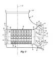
- FIG. 2is a perspective view of a mixing pipe disposed in an exhaust pipe of the aftertreatment system
- FIG. 3is a cross-sectional view of the mixing pipe and exhaust pipe of FIG. 2 ;
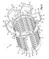
- FIG. 4is a perspective view of the mixing pipe
- FIG. 5is a plan view of a downstream end of the mixing pipe
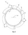
- FIG. 6is a plan view of a downstream end of another embodiment of a mixing pipe according to the principles of the present disclosure.
- FIG. 7is a cross-sectional view of another mixing pipe and exhaust pipe according to the principles of the present disclosure.
- FIG. 8is a perspective view of the mixing pipe of FIG. 7 ;
- FIG. 9is a plan view of a downstream end of the mixing pipe of FIG. 7 ;
- FIG. 10is a cross-sectional view of another mixing pipe and exhaust pipe according to the principles of the present disclosure.
- FIG. 11is a perspective view of the mixing pipe of FIG. 10 ;
- FIG. 12is a plan view of a downstream end of the mixing pipe of FIG. 10 ;
- FIG. 13is a cross-sectional view of another mixing pipe and exhaust pipe according to the principles of the present disclosure, the cross section is taken along line 13 - 13 of FIG. 14 ;
- FIG. 14is a plan view of the mixing pipe and exhaust pipe of FIG. 13 .
- Example embodimentsare provided so that this disclosure will be thorough, and will fully convey the scope to those who are skilled in the art. Numerous specific details are set forth such as examples of specific components, devices, and methods, to provide a thorough understanding of embodiments of the present disclosure. It will be apparent to those skilled in the art that specific details need not be employed, that example embodiments may be embodied in many different forms and that neither should be construed to limit the scope of the disclosure. In some example embodiments, well-known processes, well-known device structures, and well-known technologies are not described in detail.
- first, second, third, etc.may be used herein to describe various elements, components, regions, layers and/or sections, these elements, components, regions, layers and/or sections should not be limited by these terms. These terms may be only used to distinguish one element, component, region, layer or section from another region, layer or section. Terms such as “first,” “second,” and other numerical terms when used herein do not imply a sequence or order unless clearly indicated by the context. Thus, a first element, component, region, layer or section discussed below could be termed a second element, component, region, layer or section without departing from the teachings of the example embodiments.
- Spatially relative termssuch as “inner,” “outer,” “beneath,” “below,” “lower,” “above,” “upper,” and the like, may be used herein for ease of description to describe one element or feature's relationship to another element(s) or feature(s) as illustrated in the figures. Spatially relative terms may be intended to encompass different orientations of the device in use or operation in addition to the orientation depicted in the figures. For example, if the device in the figures is turned over, elements described as “below” or “beneath” other elements or features would then be oriented “above” the other elements or features. Thus, the example term “below” can encompass both an orientation of above and below. The device may be otherwise oriented (rotated 90 degrees or at other orientations) and the spatially relative descriptors used herein interpreted accordingly.
- an exhaust aftertreatment system 10may include an exhaust pipe 12 , a reductant delivery system 14 , an aftertreatment device 16 and a mixing pipe 18 .
- the exhaust pipe 12may receive exhaust gas discharged from a combustion engine 20 . Exhaust gas discharged into the exhaust pipe 12 may flow through the mixing pipe 18 and the aftertreatment device 16 before being discharged to the ambient environment.
- the exhaust pipe 12may include first and second portions 22 , 24 defining a ninety-degree bend.
- the first portion 22may be defined by a first longitudinal axis A 1 ( FIG. 3 ), and the second portion 24 may be defined by a second longitudinal axis A 2 ( FIG. 3 ).
- the exhaust pipe 12is shown in the figures as having a ninety-degree bend, it will be appreciated that the exhaust pipe 12 could have a bend of less than or greater than ninety degrees and could have any suitable configuration such as an S-shape (i.e., multiple bends), for example.
- the exhaust pipe 12may include a third portion (not shown) downstream of the second portion 24 that may be approximately parallel to the first portion 22 .
- the reductant delivery system 14may pump reductant (e.g., urea or ammonia) from a tank 26 to a reductant injector 28 that may spray the reductant into the exhaust stream at or upstream of the mixing pipe 18 .
- reductante.g., urea or ammonia
- the mixing pipe 18may mix the reductant with the exhaust gas to provide a more uniform mixture of reductant and exhaust gas before the mixture enters the aftertreatment device 16 as well as to convert urea to ammonia by promoting evaporation of the water.
- the aftertreatment device 16can be an SCR (selective catalytic reduction) catalyst, for example.
- a reaction between the reductant and the aftertreatment device 16may convert nitrogen oxides in the exhaust gas to nitrogen (N 2 ), water and/or carbon dioxide, for example.
- the mixing pipe 18may include a tubular portion 30 , and a swirler or collar 32 .
- a first portion of the exhaust gas flowing through the exhaust pipe 12may flow into the tubular portion 30 and a second portion of the exhaust gas may flow around the tubular portion 30 and through the collar 32 .
- the tubular portion 30may include an upstream end 34 and a downstream end 36 .
- the upstream end 34may abut a wall 38 of the first portion 22 of the exhaust pipe 12 .
- An injector mounting plate 40may extend through the wall 38 and into the tubular portion 30 at the upstream end 34 .
- the reductant injector 28may extend through an aperture 41 in the injector mounting plate 40 and may extend into the tubular portion 30 .
- the tubular portion 30may include a longitudinal axis that is collinear with the second longitudinal axis A 2 ( FIG. 3 ).
- the tubular portion 30may include an outer diameter that is less than an inner diameter of the first and second portions 22 , 24 of the exhaust pipe 12 .
- the tubular portion 30may include a plurality of openings 42 and a plurality of deflectors 44 arranged in rows extending around the diameter of the tubular portion 30 and in columns extending between the upstream and downstream ends 34 , 36 of the tubular portion 30 .
- the openings 42may extend through outer and inner diametrical surfaces 46 , 48 of the tubular portion 30 .
- the deflectors 44may be partially cut or stamped out of the tubular portion 30 (thereby forming the openings 42 ) and bent inward into the tubular portion 30 .
- Some of the fluid flowing through the exhaust pipe 12 from the first portion 22 to the second portion 24may enter the tubular portion 30 through the openings 42 and may be directed by the deflectors 44 in a rotational direction to generate a first swirling flow pattern within the tubular portion 30 that swirls around the longitudinal axis A 2 .
- This swirling flow patternfacilitates atomization of the reductant and mixing of the reductant with the exhaust gas.
- the swirling flow patternmay also restrict or prevent impingement of the reductant fluid on the surfaces of the mixing pipe 18 , the exhaust pipe 12 and/or the aftertreatment device 16 , which reduces the formation and/or buildup of reductant deposits on the mixing pipe, exhaust pipe 12 and the aftertreatment device 16 .
- the mixing pipe 18may include a hydrolysis coating to further reduce the formation and/or buildup of reductant deposits on the mixing pipe 18 .
- the deflectors 44are shown in FIGS. 2-5 as extending inward into the tubular portion 30 , in some embodiments, the deflectors 44 may be formed to extend outward from the outer diametrical surface 46 of the tubular portion 30 , as shown in FIG. 6 . With the deflectors 44 extending radially outward, the opportunity for reductant deposits to form on the deflectors 44 may be further reduced, while the swirling flow pattern within the tubular portion 30 is still able to be effectively generated.
- the collar 32may be generally conical in its overall shape and may extend radially outward and axially downstream from the downstream end 36 of the tubular portion 30 .
- the collar 32may be welded and/or otherwise secured to the tubular portion 30 .
- the collar 32may be integrally formed with the tubular portion 30 .
- a transition between the tubular portion 30 and the collar 32may be smooth, edgeless and/or seamless. That is, the transitions may not include steps or ridges, for example.
- the smooth, edgeless transitionsmay reduce backpressure in the flow of exhaust through the mixing pipe 18 .
- the smooth, edgeless transitionsmay also reduce or prevent the buildup of reductant deposits and/or other deposits on the mixing pipe 18 .
- the collar 32may include a plurality of blades 50 arranged in a circular array extending around the longitudinal axis of the tubular portion 30 .
- Each of the blades 50may include a body 52 and first and second tabs 54 , 56 extending from the body 52 .
- the body 52may be disposed at an angle relative to the longitudinal axis of the tubular portion 30 and may include a proximal end 58 (i.e., a radially inner end), a distal end 60 (i.e., a radially outer end), and first and second lateral edges 62 , 64 extending between the proximal and distal ends 58 , 60 , as shown in FIG. 5 .
- the angle of the body 52 relative to the longitudinal axismay be customized for a particular application to achieve a desired amount of turbulence.
- the first tab 54may extend radially inward from the second lateral edge 64 toward the longitudinal axis of the tubular portion 30 .
- the second tab 56may radially outward and axially downstream from the distal end 60 .
- the second tabs 56may contact the inner diametrical surface of the second portion 24 of the exhaust pipe 12 .
- the second tabs 56may be welded and/or otherwise fixed to the inner diametrical surface of the second portion 24 .
- each blade 50may be angled to extend in a generally clockwise direction as it extends radially outward from the tubular portion 30 when viewed from the frame of reference of FIG. 5 . It will be appreciated that in some embodiments, the blades 50 could be angled to extend in a generally counterclockwise direction as they extend radially outward from the tubular portion 30 when viewed from the frame of reference of FIG. 5 .
- the geometry of the blades 50 and the orientation of the blades 50 relative to each other, the tubular portion 30 and the exhaust pipe 12may cause the fluid flowing through the collar 32 to flow in a second rotational or swirling flow pattern around the longitudinal axis A 2 and around the first swirling flow pattern of fluid that flowed through the tubular portion 30 .
- These two coaxial swirling flow patternsmay result in improved mixture of the reductant and exhaust gas before the reductant and exhaust gas flow into the aftertreatment device 16 .
- this improved mixingcan be accomplished with a shorter length of pipe between the reductant injector 28 and the aftertreatment device 16 than may have been required for adequate mixing in prior-art aftertreatment systems.
- the blades 50 and the deflectors 44could be oriented so that the first and second swirling flow patterns rotate in the same rotational direction or in opposite rotational directions.
- the tubular portion 30could include scoops (not shown) that extend radially inward or radially outward therefrom in addition to or instead of the generally flat deflectors 44 .
- the collar 32could include scoops (not shown) in addition to or instead of the blades 50 .
- the scoopscould include a geometry that curves in three dimensions and/or spiraled geometry, for example, to induce a swirling flow pattern.
- the collar 32could be a conical or funnel-shaped member having one or more openings therein instead of a plurality of blades or scoops.
- mixing pipe 18is described above as being used in a SCR dosing application, it will be appreciate that the mixing pipe 18 could be used in a hydrocarbon dosing application, in which the mixing pipe 18 may mix injected hydrocarbon with the exhaust gas.
- the mixing pipe 118may include a tubular portion 130 and a plurality of blades 150 extending from a downstream end 136 of the tubular portion 130 .
- An injector mounting plate 140may extend through the wall 38 of the exhaust pipe 12 and engage an upstream end 134 of the tubular portion 130 .
- the reductant injector 28 described abovemay extend through an aperture 141 in the injector mounting plate 140 and may inject reductant into the tubular portion 130 .
- the mixing pipe 118may induce turbulence in the flow of exhaust gas flowing from the first portion 22 of the exhaust pipe 12 to the second portion 24 of the exhaust pipe 12 to facilitate mixing of the reductant with the exhaust gas.
- the tubular portion 130may include inner and outer diametrical surfaces 143 , 144 and a plurality of openings 142 extending through the inner and outer diametrical surfaces 143 , 144 . While the openings 142 shown in FIGS. 7 and 8 have a circular shape, it will be appreciated that the openings 142 could have any shape, such as rectangular, square, or oval, for example. Furthermore, the size of each opening 142 and the total number of openings 142 can vary, as well.
- the openings 142may be arranged in a plurality of parallel rows 146 ( FIG. 7 ) extending circumferentially around the tubular portion 130 . As shown in FIG. 7 , the openings 142 of adjacent rows 146 may be misaligned with each other in a direction parallel to the second longitudinal axis A 2 .
- the openings 142may be arranged in columns 148 (extending parallel to the second longitudinal axis A 2 ) that each include one of the openings 142 of every alternate row 146 . This arrangement of the openings 142 reduces or prevents liquid droplets that have impinged on the inner diametrical surface 143 from flowing along the inner diametrical surface 143 for any extended length.
- any path parallel (or nearly parallel) to the second longitudinal axis A 2 that such an impinged droplet may follow along the inner diametrical surface 143will eventually reach one of the openings 142 and will be drawn back into the exhaust stream by the flow of exhaust gas through and around the openings 142 .
- the blades 150may extend downstream away from the downstream end 136 of the tubular portion 130 and radially outward therefrom.
- the blades 150curve around the second longitudinal axis A 2 as they extend downstream.
- the blades 150 and the tubular portion 130may define a unitary body integrally formed from a common sheet of material.
- Transitions 152 between the tubular portion 130 and the blades 150may be smooth, edgeless and/or seamless. That is, the transitions 152 may not include steps or ridges, for example.
- the smooth, edgeless transitions 152may reduce backpressure in the flow of exhaust through the mixing pipe 118 .
- the smooth, edgeless transitions 152may also reduce or prevent the buildup of reductant deposits and/or other deposits on the mixing pipe 118 .
- the blades 150may include a generally L-shaped cross section or profile. In this manner, a first portion 154 of each blade 150 may extend substantially radially outwardly and a second portion 156 of each blade 150 may extend substantially in the downstream direction.
- the blades 150may have a generally helical shape. In some embodiments, the blades 150 may be generally flattened and angled, rather than helical. The precise number, shape and spacing of the blades 150 may be varied from that of the blades 150 depicted in FIGS. 7-9 . The shape and configuration of the blades 150 shown in FIGS. 7-9 promote turbulence in the exhaust gas flow while reducing backpressure relative to other blade configurations.
- the blades 150may be designed so that most or all of the structure that increases backpressure will also generate turbulence (i.e., the mixing pipe 118 has very little structure that increases backpressure without also increasing turbulence). It will be appreciated that any suitable number, shape and/or spacing may be employed to suit a given application. For example, the blades 150 could be shaped and/or spaced similarly to the blades shown in any of FIGS. 1-6 or 10-14 .
- another mixing pipe 218is provided that may be installed in the exhaust pipe 12 instead of the mixing pipe 18 or 118 .
- the structure and function of the mixing pipe 218may be similar or identical to that of either of the mixing pipes 18 , 118 , apart from any differences described below and/or shown in the figures. Therefore, similar features will not be described again in detail.
- the mixing pipe 218may include a tubular portion 230 and a plurality of blades 250 .
- the tubular portion 230may include a plurality of openings 242 extending radially through inner and outer diametrical surfaces 243 , 244 of the tubular portion 230 .
- Deflectors 246may be partially cut or stamped out of the tubular portion 230 (thereby forming the openings 242 ) and may extend generally radially outward from the tubular portion 230 and in a generally upstream direction. As described above, the deflectors 246 may increase the turbulence of the fluid flow within the exhaust pipe 12 and may promote a swirling motion in the fluid flow.
- the exhaust pipe 312may include a first portion 322 that is angled and/or curved relative to a second portion 324 .
- an inner elbow portion 326(disposed at a twelve o'clock position 327 of the second portion 324 relative to the frame of reference of FIG.
- Exhaust gas from the engine 20may flow through the exhaust pipe 312 from the first portion 322 to the second portion 324 .
- the mixing pipe 318may be disposed within the exhaust pipe 312 at or near the transition between the first and second portions 322 , 324 .
- the mixing pipe 318may include a tubular portion 330 and a plurality of blades 350 .
- a support ring 320may be provided to reinforce the blades 350 and support the blades 350 relative to the exhaust pipe 312 .
- the support ring 320may be a generally cylindrical and annular member disposed between an inner diametrical surface 325 of the second portion 324 of the exhaust pipe 312 and radially outermost portions 351 ( FIG. 14 ) of the blades 350 .
- a longitudinal axis of the support ring 320may be collinear with a longitudinal axis A 2 of the second portion 324 of the exhaust pipe 312 .
- the support ring 320may engage the inner diametrical surface 325 and the radially outermost portions 351 by a press fit, for example. in some embodiments, the support ring 320 may be welded and/or otherwise fixedly attached to the inner diametrical surface 325 and the radially outermost portions 351 .
- the support ring 320includes an upstream axial end 360 and a downstream axial end 362 .
- the upstream axial end 360may be disposed generally near but radially spaced apart from the inner elbow portion 326 of the exhaust pipe 312 .
- the exhaust gasin order to flow into the second portion 324 of the exhaust pipe 312 , the exhaust gas cannot flow immediately along the inner elbow portion 326 and must separate from the inner elbow portion 326 to enter the support ring 320 through the upstream axial end 360 (i.e., the support ring 320 forces the exhaust gas to take a wider turn into the second portion 324 at the twelve o'clock position 327 ).
- the mixing pipe 318may be angularly positioned within the exhaust pipe 312 so that one of the blades 350 is disposed at the twelve o'clock position 327 .
- Exhaust gas flow paths 370 from the first portion 322 to the second portion 324have radii of increasing size the farther away they are from the inner elbow portion 326 . Therefore, the exhaust gas flow path 370 flowing through the support ring 320 at the twelve o'clock position 327 has the shortest radius. Therefore, a large volume of exhaust gas may flow along the flow path 370 leading to the twelve o'clock position 327 .
- having one of the blades 350 disposed at the twelve o'clock position 327can advantageously generate more turbulence in the exhaust pipe 312 , as a large volume of exhaust gas will be influenced by the blade 350 disposed at the twelve o'clock position 327 .
- the axial length of the support ring 320may be longer or shorter relative to the blades 350 than the axial length shown in FIG. 13 .
- the support ring 320could include openings (not shown) extending radially through the inner and outer diametrical surfaces of the support ring 320 .
- blades 50 , 150 , 250 , 350are shown in the figures and described above as extending from the downstream axial end of the tubular portion 30 , 130 , 230 , 330 , it will be appreciated that the blades 50 , 150 , 250 , 350 could extend outward from a location between the upstream and downstream axial ends of the tubular portion 30 , 130 , 230 , 330 . In some embodiments, the downstream axial end of the tubular portion 30 , 130 , 230 , 330 may be located farther downstream than downstream tips of the blades 50 , 150 , 250 , 350 .
Landscapes
- Chemical & Material Sciences (AREA)
- Chemical Kinetics & Catalysis (AREA)
- Engineering & Computer Science (AREA)
- Health & Medical Sciences (AREA)
- Toxicology (AREA)
- Combustion & Propulsion (AREA)
- Mechanical Engineering (AREA)
- General Engineering & Computer Science (AREA)
- Dispersion Chemistry (AREA)
- Exhaust Gas After Treatment (AREA)
Abstract
Description
Claims (23)
Priority Applications (4)
| Application Number | Priority Date | Filing Date | Title |
|---|---|---|---|
| US14/260,555US9435240B2 (en) | 2013-08-06 | 2014-04-24 | Perforated mixing pipe with swirler |
| CN201580020574.8ACN106232955B (en) | 2014-04-24 | 2015-04-21 | Perforation mixing tube with cyclone |
| PCT/US2015/026843WO2015164356A1 (en) | 2014-04-24 | 2015-04-21 | Perforated mixing pipe with swirler |
| DE112015001958.8TDE112015001958T5 (en) | 2014-04-24 | 2015-04-21 | Perforated mixing tube with swirl body |
Applications Claiming Priority (2)
| Application Number | Priority Date | Filing Date | Title |
|---|---|---|---|
| US13/960,151US9410464B2 (en) | 2013-08-06 | 2013-08-06 | Perforated mixing pipe with swirler |
| US14/260,555US9435240B2 (en) | 2013-08-06 | 2014-04-24 | Perforated mixing pipe with swirler |
Related Parent Applications (1)
| Application Number | Title | Priority Date | Filing Date |
|---|---|---|---|
| US13/960,151Continuation-In-PartUS9410464B2 (en) | 2013-08-06 | 2013-08-06 | Perforated mixing pipe with swirler |
Publications (2)
| Publication Number | Publication Date |
|---|---|
| US20150044103A1 US20150044103A1 (en) | 2015-02-12 |
| US9435240B2true US9435240B2 (en) | 2016-09-06 |
Family
ID=52448816
Family Applications (1)
| Application Number | Title | Priority Date | Filing Date |
|---|---|---|---|
| US14/260,555ActiveUS9435240B2 (en) | 2013-08-06 | 2014-04-24 | Perforated mixing pipe with swirler |
Country Status (1)
| Country | Link |
|---|---|
| US (1) | US9435240B2 (en) |
Cited By (13)
| Publication number | Priority date | Publication date | Assignee | Title |
|---|---|---|---|---|
| US20170282135A1 (en)* | 2013-09-13 | 2017-10-05 | Donaldson Company, Inc. | Dosing and mixing arrangement for use in exhaust aftertreatment |
| US20180030874A1 (en)* | 2015-03-06 | 2018-02-01 | Tenneco Gmbh | Mix box |
| US20180112571A1 (en)* | 2015-03-30 | 2018-04-26 | Isuzu Motors Limited | Exhaust purification unit |
| US10047657B2 (en)* | 2015-01-22 | 2018-08-14 | Tenneco Automotive Operating Company Inc. | Exhaust aftertreatment system having mixer assembly |
| US10179315B2 (en)* | 2015-06-12 | 2019-01-15 | Donaldson Company, Inc. | Exhaust treatment device |
| KR101955272B1 (en)* | 2018-06-26 | 2019-03-08 | 김동업 | Automobile Exhaust Control Device with Streamlined Twisting Wings |
| US10273853B2 (en) | 2017-09-29 | 2019-04-30 | Tenneco Automotive Operating Company Inc. | Wire mesh mixing tube |
| US10995643B2 (en) | 2015-03-09 | 2021-05-04 | Tenneco Gmbh | Mixing device |
| US11098629B2 (en) | 2020-01-23 | 2021-08-24 | Cnh Industrial America Llc | Sensor shields for exhaust treatment systems of work vehicles |
| US11187133B2 (en) | 2013-08-05 | 2021-11-30 | Tenneco Gmbh | Exhaust system with mixer |
| US20220288554A1 (en)* | 2019-08-27 | 2022-09-15 | Sabic Global Technologies B.V. | Mass transfer swirler including distribution member |
| US11486289B2 (en)* | 2018-07-03 | 2022-11-01 | Cummins Emission Solutions Inc. | Body mixing decomposition reactor |
| US20230065989A1 (en)* | 2021-08-26 | 2023-03-02 | Faurecia Emission Control Technologies (Shanghai) Co., Ltd | Mixer, Mixer Assembly and Mixing Method |
Families Citing this family (16)
| Publication number | Priority date | Publication date | Assignee | Title |
|---|---|---|---|---|
| US9726063B2 (en) | 2011-09-08 | 2017-08-08 | Tenneco Automotive Operating Company Inc. | In-line flow diverter |
| US9347355B2 (en) | 2011-09-08 | 2016-05-24 | Tenneco Automotive Operating Company Inc. | In-line flow diverter |
| DE202014102872U1 (en)* | 2014-06-10 | 2014-07-09 | Tenneco Gmbh | exhaust mixer |
| DE102015104540B3 (en)* | 2015-03-25 | 2016-02-04 | Tenneco Gmbh | mixing device |
| US9534525B2 (en) | 2015-05-27 | 2017-01-03 | Tenneco Automotive Operating Company Inc. | Mixer assembly for exhaust aftertreatment system |
| DE102015108655B4 (en)* | 2015-06-01 | 2017-07-13 | Tenneco Gmbh | mixer |
| US10519832B2 (en) | 2016-05-27 | 2019-12-31 | Deere & Company | Decomposition tube for exhaust treatment systems |
| GB2557651B (en) | 2016-12-14 | 2019-08-21 | Perkins Engines Co Ltd | Pipe mixer for an aftertreatment system |
| FI128516B (en) | 2019-05-24 | 2020-06-30 | Proventia Oy | A mixer arrangement and a method of mixing for aftertreatment of exhaust gas |
| KR102180488B1 (en)* | 2019-05-27 | 2020-11-18 | 홍금표 | The exaust fumes reduction device for internal combustion engine of ship |
| EP3997314B1 (en)* | 2019-07-11 | 2024-03-06 | Donaldson Company, Inc. | Dosing conduit arrangements for exhaust aftertreatment system |
| US11225897B2 (en) | 2019-07-23 | 2022-01-18 | Tenneco Automotive Operating Company Inc. | Vehicle exhaust system |
| US11603788B2 (en)* | 2020-06-16 | 2023-03-14 | Cnh Industrial America Llc | Mixing conduits including swirler vanes for use within an exhaust treatment system |
| CN111648845B (en)* | 2020-06-22 | 2024-09-27 | 无锡威孚力达催化净化器有限责任公司 | Spiral piece formula urea mixing arrangement |
| CN114251166A (en)* | 2020-09-23 | 2022-03-29 | 佛吉亚印度私营责任有限公司 | Hybrid components for aftertreatment units of vehicle exhaust systems |
| CN115217591B (en)* | 2022-07-27 | 2023-07-04 | 无锡威孚力达催化净化器有限责任公司 | Urea mixing device capable of being crushed for multiple times and controllable in rotational flow |
Citations (65)
| Publication number | Priority date | Publication date | Assignee | Title |
|---|---|---|---|---|
| US3797240A (en) | 1971-06-02 | 1974-03-19 | Toyota Motor Co Ltd | Exhaust emission control device |
| US4043539A (en) | 1975-03-28 | 1977-08-23 | Texaco Inc. | Method and apparatus for static type fluid mixing |
| US4571938A (en) | 1982-08-27 | 1986-02-25 | Mazda Motor Corporation | Exhaust gas cleaning device for diesel engines |
| US4909635A (en) | 1988-01-05 | 1990-03-20 | Societe Anonyme Dite: Alsthom | Static device for homogenizing a flowing fluid |
| US4912920A (en) | 1989-02-02 | 1990-04-03 | Toa Nenryo Kogyo Kabushiki Kaisha | Ultrasonic burner system for regenerating a filter |
| DE3940747C1 (en)* | 1989-12-09 | 1990-07-12 | Mercedes-Benz Aktiengesellschaft, 7000 Stuttgart, De | |
| EP0470361A1 (en) | 1990-08-07 | 1992-02-12 | Zeuna-Stärker Gmbh & Co Kg | Exhaust system with particle filter and regeneration burner |
| DE4121940A1 (en) | 1991-07-03 | 1993-01-07 | Audi Ag | Method of removing soot particles from diesel exhaust - has perforated pipe inserted in front of converter |
| DE4203807A1 (en) | 1990-11-29 | 1993-08-12 | Man Nutzfahrzeuge Ag | Catalytic nitrogen oxide(s) redn. appts. for vehicles - comprises flow mixer urea evaporator hydrolysis catalyst, for exhaust gas treatment |
| US5339630A (en)* | 1992-08-28 | 1994-08-23 | General Motors Corporation | Exhaust burner catalyst preheater |
| DE4307525A1 (en) | 1993-03-10 | 1994-09-15 | Audi Ag | Method and device for the treatment of exhaust gases from an internal combustion engine |
| DE4417238A1 (en) | 1994-05-17 | 1994-09-29 | Siemens Ag | Device for reducing the amount of nitrogen oxides in the exhaust from a lean-burn internal-combustion engine |
| US5426269A (en) | 1992-06-02 | 1995-06-20 | Donaldson Company, Inc. | Muffler with catalytic converter arrangement; and method |
| JPH10231721A (en)* | 1997-02-18 | 1998-09-02 | Yutaka Giken Co Ltd | Exhaust gas purifying device for internal combustion engine |
| US6442933B2 (en) | 1998-08-11 | 2002-09-03 | Siemens Aktiengesellschaft | Device for catalytic exhaust gas purification |
| US6449947B1 (en) | 2001-10-17 | 2002-09-17 | Fleetguard, Inc. | Low pressure injection and turbulent mixing in selective catalytic reduction system |
| EP1262644A2 (en) | 2001-06-01 | 2002-12-04 | Nelson Burgess Limited | Catalytic converter |
| US6536420B1 (en)* | 1996-03-18 | 2003-03-25 | Theodore Y. Cheng | Gas swirling device for internal combustion engine |
| WO2003036056A1 (en) | 2001-10-25 | 2003-05-01 | Eminox Limited | Gas treatment apparatus |
| US6722123B2 (en) | 2001-10-17 | 2004-04-20 | Fleetguard, Inc. | Exhaust aftertreatment device, including chemical mixing and acoustic effects |
| US6767378B2 (en) | 2001-09-19 | 2004-07-27 | Komatsu Ltd. | Exhaust gas purifying system for internal combustion engine |
| US20060218902A1 (en) | 2005-03-31 | 2006-10-05 | Solar Turbines Incorporated | Burner assembly for particulate trap regeneration |
| US20070245718A1 (en)* | 2006-04-24 | 2007-10-25 | Cheng C R | Exhaust aftertreatment mixer with stamped muffler flange |
| US20070274877A1 (en)* | 2004-07-29 | 2007-11-29 | Eminox Limited (A British Company) | Gas treatment appartatus |
| US7328572B2 (en) | 2006-02-23 | 2008-02-12 | Fleetguard, Inc. | Exhaust aftertreatment device with star-plugged turbulator |
| US20080184700A1 (en)* | 2007-01-30 | 2008-08-07 | J. Eberspaecher Gmbh & Co. Kg | Exhaust system for an internal combustion engine |
| US20080216470A1 (en) | 2007-03-09 | 2008-09-11 | Sedlacek Jeffrey T | Exhaust Aftertreatment System with Flow Distribution |
| US20080250776A1 (en)* | 2007-04-16 | 2008-10-16 | Gm Global Technology Operations, Inc. | Mixing Apparatus for an Exhaust After-Treatment System |
| US20080307780A1 (en) | 2007-06-13 | 2008-12-18 | Iverson Robert J | Emission abatement assembly having a mixing baffle and associated method |
| US20090019843A1 (en) | 2007-07-17 | 2009-01-22 | Ford Global Technologies, Llc | Approach for Delivering a Liquid Reductant into an Exhaust Flow of a Fuel Burning Engine |
| WO2009024815A2 (en) | 2007-08-17 | 2009-02-26 | Emcon Technologies Germany (Augsburg) Gmbh | An exhaust system |
| US20090178395A1 (en) | 2008-01-15 | 2009-07-16 | Huffmeyer Christopher R | Method and Apparatus for Regenerating a Particulate Filter of an Emission Abatement Assembly |
| US7562521B2 (en) | 2004-02-02 | 2009-07-21 | Tokyo Roki Co., Ltd. | SCR muffler |
| US20090255242A1 (en)* | 2008-04-09 | 2009-10-15 | Woodward Governor Company | Low Pressure Drop Mixer for Radial Mixing of Internal Combustion Engine Exhaust Flows, Combustor Incorporating Same, and Methods of Mixing |
| EP2111916A1 (en) | 2008-04-21 | 2009-10-28 | Swenox AB | Mixing device for mixing a gas with an additive fluid |
| US20090313979A1 (en) | 2007-02-23 | 2009-12-24 | Hino Motors, Ltd. | Exhaust emission control device |
| DE102008029110A1 (en)* | 2008-06-20 | 2009-12-24 | J. Eberspächer GmbH & Co. KG | Mixing and evaporating device for exhaust-gas system of internal combustion engine, particularly motor vehicle, has ring body which has internal shovel, where shovel is fastened with retaining elements in exhaust gas guiding pipe |
| US20100000205A1 (en)* | 2008-07-01 | 2010-01-07 | General Motors Global Technology Operations, Inc. | Apparatus and method for cooling an exhaust gas |
| EP2168672A1 (en) | 2008-09-24 | 2010-03-31 | Emcon Technologies UK Limited | Mixing device |
| US20100263359A1 (en)* | 2007-07-25 | 2010-10-21 | Heinrich Gillet Gmbh | Apparatus for the Aftertreatment of the Exhaust Gases of Diesel Engines |
| DE102009036511A1 (en)* | 2009-08-07 | 2011-02-10 | Friedrich Boysen Gmbh & Co. Kg | Exhaust system for e.g. diesel engine, has waste gas duct provided between input and exhaust gas treatment devices, and including deflection device for partial feedback of exhaust gas flow against main exhaust gas flow direction |
| US20110094206A1 (en)* | 2009-10-27 | 2011-04-28 | Cummins Filtration Ip, Inc | Reductant injection and decomposition system |
| US20110099978A1 (en) | 2009-04-02 | 2011-05-05 | Cummins Ip, Inc | Reductant decomposition system |
| US8033104B2 (en) | 2008-07-09 | 2011-10-11 | Ford Global Technologies, Llc | Selective catalytic reduction (SCR) catalyst injection systems |
| US20110308234A1 (en) | 2010-06-22 | 2011-12-22 | Korneel De Rudder | Dosing and mixing arrangement for use in exhaust aftertreatment |
| US8141353B2 (en) | 2008-04-25 | 2012-03-27 | Tenneco Automotive Operating Company Inc. | Exhaust gas additive/treatment system and mixer for use therein |
| WO2012044233A1 (en) | 2010-09-30 | 2012-04-05 | Scania Cv Ab | Arrangement for introducing a liquid medium into exhaust gases from a combustion engine |
| US8181446B2 (en) | 2005-05-17 | 2012-05-22 | Nissan Diesel Motor Co., Ltd. | Exhaust emission purification apparatus for engine |
| EP2465602A2 (en) | 2010-12-14 | 2012-06-20 | Proventia Emission Control Oy | Method and device for exhaust gas cleaning |
| US8215450B2 (en) | 2010-02-05 | 2012-07-10 | Chih-Chien Chien | Exhaust muffler device |
| US20120204541A1 (en) | 2011-02-14 | 2012-08-16 | GM Global Technology Operations LLC | Exhaust mixer element and method for mixing |
| US8272777B2 (en) | 2008-04-21 | 2012-09-25 | Heinrich Gillet Gmbh (Tenneco) | Method for mixing an exhaust gas flow |
| US8276372B2 (en) | 2007-02-23 | 2012-10-02 | Hino Motors, Ltd. | Exhaust emission control device |
| US8359838B2 (en) | 2007-05-01 | 2013-01-29 | Mitsubishi Fuso Truck And Bus Corporation | Exhaust purification apparatus for an engine |
| US8375709B2 (en) | 2009-11-17 | 2013-02-19 | Tenneco Automotive Operating Company Inc. | Exhaust gas additive/treatment system and mixer for use therein |
| US8397495B2 (en) | 2008-06-26 | 2013-03-19 | Tenneco Automotive Operating Company Inc. | Exhaust gas additive/treatment system and mixer for use therein |
| US8397492B2 (en) | 2008-05-27 | 2013-03-19 | Hino Motors, Ltd. | Exhaust emission control device |
| US20130098002A1 (en) | 2010-06-10 | 2013-04-25 | Dif Die Ideenfabrik Gmbh | Exhaust gas treatment device, method for producing a tube for an exhaust gas treatment device and watercraft having an exhaust gas treatment device |
| WO2013087852A2 (en)* | 2011-12-14 | 2013-06-20 | Friedrich Boysen Gmbh & Co. Kg | Mixing apparatus |
| US20130164181A1 (en)* | 2011-12-27 | 2013-06-27 | Tadashi Iijima | Reducing agent aqueous solution mixing device and exhaust gas post-treatment device |
| US8499548B2 (en) | 2008-12-17 | 2013-08-06 | Donaldson Company, Inc. | Flow device for an exhaust system |
| DE102012010878A1 (en)* | 2012-06-01 | 2013-12-05 | Daimler Ag | Reductant addition and treatment system of a motor vehicle |
| US20140033686A1 (en) | 2010-12-27 | 2014-02-06 | Friedrich Boysen Gmbh & Co. Kg | Device for distributing fluids in exhaust systems |
| US20140077400A1 (en)* | 2008-04-21 | 2014-03-20 | Tenneco Automotive Operating Company Inc. | Exhaust Gas Flow Mixer |
| DE102013211662A1 (en)* | 2013-06-20 | 2014-12-24 | Friedrich Boysen Gmbh & Co. Kg | Mixer means |
- 2014
- 2014-04-24USUS14/260,555patent/US9435240B2/enactiveActive
Patent Citations (69)
| Publication number | Priority date | Publication date | Assignee | Title |
|---|---|---|---|---|
| US3797240A (en) | 1971-06-02 | 1974-03-19 | Toyota Motor Co Ltd | Exhaust emission control device |
| US4043539A (en) | 1975-03-28 | 1977-08-23 | Texaco Inc. | Method and apparatus for static type fluid mixing |
| US4571938A (en) | 1982-08-27 | 1986-02-25 | Mazda Motor Corporation | Exhaust gas cleaning device for diesel engines |
| US4909635A (en) | 1988-01-05 | 1990-03-20 | Societe Anonyme Dite: Alsthom | Static device for homogenizing a flowing fluid |
| US4912920A (en) | 1989-02-02 | 1990-04-03 | Toa Nenryo Kogyo Kabushiki Kaisha | Ultrasonic burner system for regenerating a filter |
| DE3940747C1 (en)* | 1989-12-09 | 1990-07-12 | Mercedes-Benz Aktiengesellschaft, 7000 Stuttgart, De | |
| EP0470361A1 (en) | 1990-08-07 | 1992-02-12 | Zeuna-Stärker Gmbh & Co Kg | Exhaust system with particle filter and regeneration burner |
| DE4203807A1 (en) | 1990-11-29 | 1993-08-12 | Man Nutzfahrzeuge Ag | Catalytic nitrogen oxide(s) redn. appts. for vehicles - comprises flow mixer urea evaporator hydrolysis catalyst, for exhaust gas treatment |
| DE4121940A1 (en) | 1991-07-03 | 1993-01-07 | Audi Ag | Method of removing soot particles from diesel exhaust - has perforated pipe inserted in front of converter |
| US5426269A (en) | 1992-06-02 | 1995-06-20 | Donaldson Company, Inc. | Muffler with catalytic converter arrangement; and method |
| US5339630A (en)* | 1992-08-28 | 1994-08-23 | General Motors Corporation | Exhaust burner catalyst preheater |
| DE4307525A1 (en) | 1993-03-10 | 1994-09-15 | Audi Ag | Method and device for the treatment of exhaust gases from an internal combustion engine |
| DE4417238A1 (en) | 1994-05-17 | 1994-09-29 | Siemens Ag | Device for reducing the amount of nitrogen oxides in the exhaust from a lean-burn internal-combustion engine |
| US6536420B1 (en)* | 1996-03-18 | 2003-03-25 | Theodore Y. Cheng | Gas swirling device for internal combustion engine |
| JPH10231721A (en)* | 1997-02-18 | 1998-09-02 | Yutaka Giken Co Ltd | Exhaust gas purifying device for internal combustion engine |
| US6442933B2 (en) | 1998-08-11 | 2002-09-03 | Siemens Aktiengesellschaft | Device for catalytic exhaust gas purification |
| US6722124B2 (en) | 2001-06-01 | 2004-04-20 | Nelson Burgess Limited | Catalytic converter |
| EP1262644A2 (en) | 2001-06-01 | 2002-12-04 | Nelson Burgess Limited | Catalytic converter |
| US6767378B2 (en) | 2001-09-19 | 2004-07-27 | Komatsu Ltd. | Exhaust gas purifying system for internal combustion engine |
| US6722123B2 (en) | 2001-10-17 | 2004-04-20 | Fleetguard, Inc. | Exhaust aftertreatment device, including chemical mixing and acoustic effects |
| US6449947B1 (en) | 2001-10-17 | 2002-09-17 | Fleetguard, Inc. | Low pressure injection and turbulent mixing in selective catalytic reduction system |
| WO2003036056A1 (en) | 2001-10-25 | 2003-05-01 | Eminox Limited | Gas treatment apparatus |
| US7562521B2 (en) | 2004-02-02 | 2009-07-21 | Tokyo Roki Co., Ltd. | SCR muffler |
| US20070274877A1 (en)* | 2004-07-29 | 2007-11-29 | Eminox Limited (A British Company) | Gas treatment appartatus |
| US20060218902A1 (en) | 2005-03-31 | 2006-10-05 | Solar Turbines Incorporated | Burner assembly for particulate trap regeneration |
| US8181446B2 (en) | 2005-05-17 | 2012-05-22 | Nissan Diesel Motor Co., Ltd. | Exhaust emission purification apparatus for engine |
| US7328572B2 (en) | 2006-02-23 | 2008-02-12 | Fleetguard, Inc. | Exhaust aftertreatment device with star-plugged turbulator |
| US20070245718A1 (en)* | 2006-04-24 | 2007-10-25 | Cheng C R | Exhaust aftertreatment mixer with stamped muffler flange |
| US20080184700A1 (en)* | 2007-01-30 | 2008-08-07 | J. Eberspaecher Gmbh & Co. Kg | Exhaust system for an internal combustion engine |
| US8276372B2 (en) | 2007-02-23 | 2012-10-02 | Hino Motors, Ltd. | Exhaust emission control device |
| US8347610B2 (en) | 2007-02-23 | 2013-01-08 | Hino Motors, Ltd. | Exhaust emission control device |
| US20090313979A1 (en) | 2007-02-23 | 2009-12-24 | Hino Motors, Ltd. | Exhaust emission control device |
| US20080216470A1 (en) | 2007-03-09 | 2008-09-11 | Sedlacek Jeffrey T | Exhaust Aftertreatment System with Flow Distribution |
| US7748212B2 (en) | 2007-03-09 | 2010-07-06 | Cummins Filtration Ip, Inc. | Exhaust aftertreatment system with flow distribution |
| US20080250776A1 (en)* | 2007-04-16 | 2008-10-16 | Gm Global Technology Operations, Inc. | Mixing Apparatus for an Exhaust After-Treatment System |
| US8359838B2 (en) | 2007-05-01 | 2013-01-29 | Mitsubishi Fuso Truck And Bus Corporation | Exhaust purification apparatus for an engine |
| US20080307780A1 (en) | 2007-06-13 | 2008-12-18 | Iverson Robert J | Emission abatement assembly having a mixing baffle and associated method |
| US20090019843A1 (en) | 2007-07-17 | 2009-01-22 | Ford Global Technologies, Llc | Approach for Delivering a Liquid Reductant into an Exhaust Flow of a Fuel Burning Engine |
| US20100263359A1 (en)* | 2007-07-25 | 2010-10-21 | Heinrich Gillet Gmbh | Apparatus for the Aftertreatment of the Exhaust Gases of Diesel Engines |
| WO2009024815A2 (en) | 2007-08-17 | 2009-02-26 | Emcon Technologies Germany (Augsburg) Gmbh | An exhaust system |
| US20090178395A1 (en) | 2008-01-15 | 2009-07-16 | Huffmeyer Christopher R | Method and Apparatus for Regenerating a Particulate Filter of an Emission Abatement Assembly |
| US20090255242A1 (en)* | 2008-04-09 | 2009-10-15 | Woodward Governor Company | Low Pressure Drop Mixer for Radial Mixing of Internal Combustion Engine Exhaust Flows, Combustor Incorporating Same, and Methods of Mixing |
| US20140077400A1 (en)* | 2008-04-21 | 2014-03-20 | Tenneco Automotive Operating Company Inc. | Exhaust Gas Flow Mixer |
| EP2111916A1 (en) | 2008-04-21 | 2009-10-28 | Swenox AB | Mixing device for mixing a gas with an additive fluid |
| US8272777B2 (en) | 2008-04-21 | 2012-09-25 | Heinrich Gillet Gmbh (Tenneco) | Method for mixing an exhaust gas flow |
| US8141353B2 (en) | 2008-04-25 | 2012-03-27 | Tenneco Automotive Operating Company Inc. | Exhaust gas additive/treatment system and mixer for use therein |
| US8397492B2 (en) | 2008-05-27 | 2013-03-19 | Hino Motors, Ltd. | Exhaust emission control device |
| DE102008029110A1 (en)* | 2008-06-20 | 2009-12-24 | J. Eberspächer GmbH & Co. KG | Mixing and evaporating device for exhaust-gas system of internal combustion engine, particularly motor vehicle, has ring body which has internal shovel, where shovel is fastened with retaining elements in exhaust gas guiding pipe |
| US8397495B2 (en) | 2008-06-26 | 2013-03-19 | Tenneco Automotive Operating Company Inc. | Exhaust gas additive/treatment system and mixer for use therein |
| US20100000205A1 (en)* | 2008-07-01 | 2010-01-07 | General Motors Global Technology Operations, Inc. | Apparatus and method for cooling an exhaust gas |
| US8033104B2 (en) | 2008-07-09 | 2011-10-11 | Ford Global Technologies, Llc | Selective catalytic reduction (SCR) catalyst injection systems |
| EP2168672A1 (en) | 2008-09-24 | 2010-03-31 | Emcon Technologies UK Limited | Mixing device |
| US8499548B2 (en) | 2008-12-17 | 2013-08-06 | Donaldson Company, Inc. | Flow device for an exhaust system |
| US20110099978A1 (en) | 2009-04-02 | 2011-05-05 | Cummins Ip, Inc | Reductant decomposition system |
| DE102009036511A1 (en)* | 2009-08-07 | 2011-02-10 | Friedrich Boysen Gmbh & Co. Kg | Exhaust system for e.g. diesel engine, has waste gas duct provided between input and exhaust gas treatment devices, and including deflection device for partial feedback of exhaust gas flow against main exhaust gas flow direction |
| US8240137B2 (en) | 2009-10-27 | 2012-08-14 | Cummins Filtration Ip, Inc. | Reductant injection and decomposition system |
| US20110094206A1 (en)* | 2009-10-27 | 2011-04-28 | Cummins Filtration Ip, Inc | Reductant injection and decomposition system |
| US8375709B2 (en) | 2009-11-17 | 2013-02-19 | Tenneco Automotive Operating Company Inc. | Exhaust gas additive/treatment system and mixer for use therein |
| US8215450B2 (en) | 2010-02-05 | 2012-07-10 | Chih-Chien Chien | Exhaust muffler device |
| US20130098002A1 (en) | 2010-06-10 | 2013-04-25 | Dif Die Ideenfabrik Gmbh | Exhaust gas treatment device, method for producing a tube for an exhaust gas treatment device and watercraft having an exhaust gas treatment device |
| US20110308234A1 (en) | 2010-06-22 | 2011-12-22 | Korneel De Rudder | Dosing and mixing arrangement for use in exhaust aftertreatment |
| WO2012044233A1 (en) | 2010-09-30 | 2012-04-05 | Scania Cv Ab | Arrangement for introducing a liquid medium into exhaust gases from a combustion engine |
| EP2465602A2 (en) | 2010-12-14 | 2012-06-20 | Proventia Emission Control Oy | Method and device for exhaust gas cleaning |
| US20140033686A1 (en) | 2010-12-27 | 2014-02-06 | Friedrich Boysen Gmbh & Co. Kg | Device for distributing fluids in exhaust systems |
| US20120204541A1 (en) | 2011-02-14 | 2012-08-16 | GM Global Technology Operations LLC | Exhaust mixer element and method for mixing |
| WO2013087852A2 (en)* | 2011-12-14 | 2013-06-20 | Friedrich Boysen Gmbh & Co. Kg | Mixing apparatus |
| US20130164181A1 (en)* | 2011-12-27 | 2013-06-27 | Tadashi Iijima | Reducing agent aqueous solution mixing device and exhaust gas post-treatment device |
| DE102012010878A1 (en)* | 2012-06-01 | 2013-12-05 | Daimler Ag | Reductant addition and treatment system of a motor vehicle |
| DE102013211662A1 (en)* | 2013-06-20 | 2014-12-24 | Friedrich Boysen Gmbh & Co. Kg | Mixer means |
Non-Patent Citations (1)
| Title |
|---|
| Machine Translation of DE 102008029110, Translated on Nov. 16, 2015.* |
Cited By (28)
| Publication number | Priority date | Publication date | Assignee | Title |
|---|---|---|---|---|
| US11187133B2 (en) | 2013-08-05 | 2021-11-30 | Tenneco Gmbh | Exhaust system with mixer |
| US10369533B2 (en)* | 2013-09-13 | 2019-08-06 | Donaldson Company, Inc. | Dosing and mixing arrangement for use in exhaust aftertreatment |
| US20190351379A1 (en)* | 2013-09-13 | 2019-11-21 | Donaldson Company, Inc. | Dosing and mixing arrangement for use in exhaust aftertreatment |
| US11465108B2 (en)* | 2013-09-13 | 2022-10-11 | Donaldson Company, Inc. | Dosing and mixing arrangement for use in exhaust aftertreatment |
| US10960366B2 (en)* | 2013-09-13 | 2021-03-30 | Donaldson Company, Inc. | Dosing and mixing arrangement for use in exhaust aftertreatment |
| US20170282135A1 (en)* | 2013-09-13 | 2017-10-05 | Donaldson Company, Inc. | Dosing and mixing arrangement for use in exhaust aftertreatment |
| US10047657B2 (en)* | 2015-01-22 | 2018-08-14 | Tenneco Automotive Operating Company Inc. | Exhaust aftertreatment system having mixer assembly |
| US10273855B2 (en) | 2015-01-22 | 2019-04-30 | Tenneco Automotive Operating Company Inc. | Exhaust aftertreatment system having mixer assembly |
| US10711677B2 (en) | 2015-01-22 | 2020-07-14 | Tenneco Automotive Operating Company Inc. | Exhaust aftertreatment system having mixer assembly |
| US10626773B2 (en)* | 2015-03-06 | 2020-04-21 | Tenneco Gmbh | Mix box |
| US20180030874A1 (en)* | 2015-03-06 | 2018-02-01 | Tenneco Gmbh | Mix box |
| US11466606B2 (en) | 2015-03-09 | 2022-10-11 | Tenneco Gmbh | Mixing device |
| US12158096B2 (en) | 2015-03-09 | 2024-12-03 | Tenneco Gmbh | Mixer assembly |
| US10995643B2 (en) | 2015-03-09 | 2021-05-04 | Tenneco Gmbh | Mixing device |
| US11702975B2 (en) | 2015-03-09 | 2023-07-18 | Tenneco Gmbh | Mixer assembly |
| US20180112571A1 (en)* | 2015-03-30 | 2018-04-26 | Isuzu Motors Limited | Exhaust purification unit |
| US11149611B2 (en)* | 2015-03-30 | 2021-10-19 | Isuzu Motors Limited | Exhaust purification unit |
| US10179315B2 (en)* | 2015-06-12 | 2019-01-15 | Donaldson Company, Inc. | Exhaust treatment device |
| US10940451B2 (en) | 2015-06-12 | 2021-03-09 | Donaldson Company, Inc. | Exhaust treatment device |
| US10273853B2 (en) | 2017-09-29 | 2019-04-30 | Tenneco Automotive Operating Company Inc. | Wire mesh mixing tube |
| KR101955272B1 (en)* | 2018-06-26 | 2019-03-08 | 김동업 | Automobile Exhaust Control Device with Streamlined Twisting Wings |
| US11486289B2 (en)* | 2018-07-03 | 2022-11-01 | Cummins Emission Solutions Inc. | Body mixing decomposition reactor |
| US11891937B2 (en) | 2018-07-03 | 2024-02-06 | Cummins Emission Solutions Inc. | Body mixing decomposition reactor |
| US20220288554A1 (en)* | 2019-08-27 | 2022-09-15 | Sabic Global Technologies B.V. | Mass transfer swirler including distribution member |
| US12303859B2 (en)* | 2019-08-27 | 2025-05-20 | Sabic Global Technologies B.V. | Mass transfer swirler including distribution member |
| US11098629B2 (en) | 2020-01-23 | 2021-08-24 | Cnh Industrial America Llc | Sensor shields for exhaust treatment systems of work vehicles |
| US20230065989A1 (en)* | 2021-08-26 | 2023-03-02 | Faurecia Emission Control Technologies (Shanghai) Co., Ltd | Mixer, Mixer Assembly and Mixing Method |
| US12186717B2 (en)* | 2021-08-26 | 2025-01-07 | Cummins Emission Solutions Inc. | Mixer, mixer assembly and mixing method |
Also Published As
| Publication number | Publication date |
|---|---|
| US20150044103A1 (en) | 2015-02-12 |
Similar Documents
| Publication | Publication Date | Title |
|---|---|---|
| US9435240B2 (en) | Perforated mixing pipe with swirler | |
| US9410464B2 (en) | Perforated mixing pipe with swirler | |
| WO2015164356A1 (en) | Perforated mixing pipe with swirler | |
| US10427099B2 (en) | Dual auger mixing system | |
| EP2512642B1 (en) | Mixing system for an exhaust gases after-treatment arrangement | |
| US10603642B2 (en) | Dosing and mixing arrangement for use in exhaust aftertreatment | |
| CN106014560B (en) | Mixer and vehicle exhaust aftertreatment device for mixing exhaust and treatment fluid | |
| EP3030767B1 (en) | Method, apparatus and system for aftertreatment of exhaust gas | |
| RU2590174C2 (en) | Apparatus for distributing fluid in exhaust systems | |
| JP6596437B2 (en) | Injection and mixing equipment | |
| US8800276B2 (en) | Mixing system | |
| US9534525B2 (en) | Mixer assembly for exhaust aftertreatment system | |
| EP3327263B1 (en) | Apparatus for aftertreatment of exhaust gas comprising inline housing | |
| US20160115844A1 (en) | Dosing and mixing arrangement for use in exhaust aftertreatment | |
| CN107980078B (en) | Exhaust gas aftertreatment device for an internal combustion engine of a motor vehicle | |
| CN105765192A (en) | Exhaust gas post-treatment device | |
| JP2011206751A (en) | Fluid mixing apparatus and denitrification apparatus | |
| GB2533790A (en) | Method, apparatus and device for improved aftertreatment of exhaust gas |
Legal Events
| Date | Code | Title | Description |
|---|---|---|---|
| AS | Assignment | Owner name:JPMORGAN CHASE BANK, N.A., AS ADMINISTRATIVE AGENT Free format text:SECURITY INTEREST;ASSIGNOR:TENNECO AUTOMOTIVE OPERATING COMPANY INC.;REEL/FRAME:034674/0291 Effective date:20141208 | |
| AS | Assignment | Owner name:TENNECO AUTOMOTIVE OPERATING COMPANY INC., ILLINOI Free format text:ASSIGNMENT OF ASSIGNORS INTEREST;ASSIGNORS:SAMPATH, MANOJ K.;HICKS, JOSHUA;FLOYD, RYAN A.;REEL/FRAME:035161/0130 Effective date:20150302 | |
| STCF | Information on status: patent grant | Free format text:PATENTED CASE | |
| FEPP | Fee payment procedure | Free format text:PAYOR NUMBER ASSIGNED (ORIGINAL EVENT CODE: ASPN); ENTITY STATUS OF PATENT OWNER: LARGE ENTITY | |
| AS | Assignment | Owner name:JPMORGAN CHASE BANK, N.A., AS ADMINISTRATIVE AGENT, ILLINOIS Free format text:GRANT OF SECURITY INTEREST IN PATENT RIGHTS;ASSIGNOR:TENNECO AUTOMOTIVE OPERATING COMPANY INC.;REEL/FRAME:042809/0515 Effective date:20170512 Owner name:JPMORGAN CHASE BANK, N.A., AS ADMINISTRATIVE AGENT Free format text:GRANT OF SECURITY INTEREST IN PATENT RIGHTS;ASSIGNOR:TENNECO AUTOMOTIVE OPERATING COMPANY INC.;REEL/FRAME:042809/0515 Effective date:20170512 | |
| AS | Assignment | Owner name:WILMINGTON TRUST, NATIONAL ASSOCIATION, AS COLLATERAL TRUSTEE, MINNESOTA Free format text:CONFIRMATORY GRANT OF SECURITY INTERESTS IN UNITED STATES PATENTS;ASSIGNORS:TENNECO INC.;TENNECO AUTOMOTIVE OPERATING COMPANY INC.;TENNECO INTERNATIONAL HOLDING CORP.;AND OTHERS;REEL/FRAME:047223/0001 Effective date:20181001 Owner name:WILMINGTON TRUST, NATIONAL ASSOCIATION, AS COLLATE Free format text:CONFIRMATORY GRANT OF SECURITY INTERESTS IN UNITED STATES PATENTS;ASSIGNORS:TENNECO INC.;TENNECO AUTOMOTIVE OPERATING COMPANY INC.;TENNECO INTERNATIONAL HOLDING CORP.;AND OTHERS;REEL/FRAME:047223/0001 Effective date:20181001 | |
| AS | Assignment | Owner name:TENNECO AUTOMOTIVE OPERATING COMPANY INC., ILLINOIS Free format text:RELEASE BY SECURED PARTY;ASSIGNOR:JPMORGAN CHASE BANK, N.A.;REEL/FRAME:048099/0716 Effective date:20181001 Owner name:TENNECO AUTOMOTIVE OPERATING COMPANY INC., ILLINOI Free format text:RELEASE BY SECURED PARTY;ASSIGNOR:JPMORGAN CHASE BANK, N.A.;REEL/FRAME:048099/0716 Effective date:20181001 | |
| MAFP | Maintenance fee payment | Free format text:PAYMENT OF MAINTENANCE FEE, 4TH YEAR, LARGE ENTITY (ORIGINAL EVENT CODE: M1551); ENTITY STATUS OF PATENT OWNER: LARGE ENTITY Year of fee payment:4 | |
| AS | Assignment | Owner name:WILMINGTON TRUST, NATIONAL ASSOCIATION, MINNESOTA Free format text:SECURITY AGREEMENT;ASSIGNORS:TENNECO INC.;THE PULLMAN COMPANY;FEDERAL-MOGUL IGNITION LLC;AND OTHERS;REEL/FRAME:054555/0592 Effective date:20201130 | |
| AS | Assignment | Owner name:TENNECO AUTOMOTIVE OPERATING COMPANY INC., ILLINOIS Free format text:CONFIRMATION OF TERMINATION AND RELEASE OF SECURITY INTEREST IN PATENT RIGHTS (R/F 34674/0291);ASSIGNOR:JPMORGAN CHASE BANK, N.A., AS ADMINISTRATIVE AGENT;REEL/FRAME:055429/0503 Effective date:20210226 | |
| AS | Assignment | Owner name:WILMINGTON TRUST, NATIONAL ASSOCIATION, MINNESOTA Free format text:SECURITY AGREEMENT;ASSIGNORS:TENNECO INC.;TENNECO AUTOMOTIVE OPERATING COMPANY INC.;THE PULLMAN COMPANY;AND OTHERS;REEL/FRAME:055626/0065 Effective date:20210317 | |
| AS | Assignment | Owner name:FEDERAL-MOGUL PRODUCTS US LLC, MICHIGAN Free format text:RELEASE BY SECURED PARTY;ASSIGNOR:WILMINGTON TRUST, NATIONAL ASSOCIATION;REEL/FRAME:061975/0218 Effective date:20221117 Owner name:FEDERAL-MOGUL FINANCING CORPORATION, MICHIGAN Free format text:RELEASE BY SECURED PARTY;ASSIGNOR:WILMINGTON TRUST, NATIONAL ASSOCIATION;REEL/FRAME:061975/0218 Effective date:20221117 Owner name:FEDERAL-MOGUL FILTRATION LLC, MICHIGAN Free format text:RELEASE BY SECURED PARTY;ASSIGNOR:WILMINGTON TRUST, NATIONAL ASSOCIATION;REEL/FRAME:061975/0218 Effective date:20221117 Owner name:BECK ARNLEY HOLDINGS LLC, MICHIGAN Free format text:RELEASE BY SECURED PARTY;ASSIGNOR:WILMINGTON TRUST, NATIONAL ASSOCIATION;REEL/FRAME:061975/0218 Effective date:20221117 Owner name:FEDERAL-MOGUL SEVIERVILLE, LLC, MICHIGAN Free format text:RELEASE BY SECURED PARTY;ASSIGNOR:WILMINGTON TRUST, NATIONAL ASSOCIATION;REEL/FRAME:061975/0218 Effective date:20221117 Owner name:FEDERAL-MOGUL VALVE TRAIN INTERNATIONAL LLC, MICHIGAN Free format text:RELEASE BY SECURED PARTY;ASSIGNOR:WILMINGTON TRUST, NATIONAL ASSOCIATION;REEL/FRAME:061975/0218 Effective date:20221117 Owner name:F-M TSC REAL ESTATE HOLDINGS LLC, MICHIGAN Free format text:RELEASE BY SECURED PARTY;ASSIGNOR:WILMINGTON TRUST, NATIONAL ASSOCIATION;REEL/FRAME:061975/0218 Effective date:20221117 Owner name:F-M MOTORPARTS TSC LLC, MICHIGAN Free format text:RELEASE BY SECURED PARTY;ASSIGNOR:WILMINGTON TRUST, NATIONAL ASSOCIATION;REEL/FRAME:061975/0218 Effective date:20221117 Owner name:FEDERAL-MOGUL CHASSIS LLC, MICHIGAN Free format text:RELEASE BY SECURED PARTY;ASSIGNOR:WILMINGTON TRUST, NATIONAL ASSOCIATION;REEL/FRAME:061975/0218 Effective date:20221117 Owner name:FEDERAL-MOGUL MOTORPARTS LLC, MICHIGAN Free format text:RELEASE BY SECURED PARTY;ASSIGNOR:WILMINGTON TRUST, NATIONAL ASSOCIATION;REEL/FRAME:061975/0218 Effective date:20221117 Owner name:FEDERAL-MOGUL IGNITION LLC, MICHIGAN Free format text:RELEASE BY SECURED PARTY;ASSIGNOR:WILMINGTON TRUST, NATIONAL ASSOCIATION;REEL/FRAME:061975/0218 Effective date:20221117 Owner name:FEDERAL-MOGUL PISTON RINGS, LLC, MICHIGAN Free format text:RELEASE BY SECURED PARTY;ASSIGNOR:WILMINGTON TRUST, NATIONAL ASSOCIATION;REEL/FRAME:061975/0218 Effective date:20221117 Owner name:FEDERAL-MOGUL POWERTRAIN IP LLC, MICHIGAN Free format text:RELEASE BY SECURED PARTY;ASSIGNOR:WILMINGTON TRUST, NATIONAL ASSOCIATION;REEL/FRAME:061975/0218 Effective date:20221117 Owner name:FEDERAL-MOGUL POWERTRAIN LLC, MICHIGAN Free format text:RELEASE BY SECURED PARTY;ASSIGNOR:WILMINGTON TRUST, NATIONAL ASSOCIATION;REEL/FRAME:061975/0218 Effective date:20221117 Owner name:MUZZY-LYON AUTO PARTS LLC, ILLINOIS Free format text:RELEASE BY SECURED PARTY;ASSIGNOR:WILMINGTON TRUST, NATIONAL ASSOCIATION;REEL/FRAME:061975/0218 Effective date:20221117 Owner name:FELT PRODUCTS MFG. CO. LLC, ILLINOIS Free format text:RELEASE BY SECURED PARTY;ASSIGNOR:WILMINGTON TRUST, NATIONAL ASSOCIATION;REEL/FRAME:061975/0218 Effective date:20221117 Owner name:FEDERAL-MOGUL WORLD WIDE LLC, MICHIGAN Free format text:RELEASE BY SECURED PARTY;ASSIGNOR:WILMINGTON TRUST, NATIONAL ASSOCIATION;REEL/FRAME:061975/0218 Effective date:20221117 Owner name:CARTER AUTOMOTIVE COMPANY LLC, ILLINOIS Free format text:RELEASE BY SECURED PARTY;ASSIGNOR:WILMINGTON TRUST, NATIONAL ASSOCIATION;REEL/FRAME:061975/0218 Effective date:20221117 Owner name:TMC TEXAS INC., ILLINOIS Free format text:RELEASE BY SECURED PARTY;ASSIGNOR:WILMINGTON TRUST, NATIONAL ASSOCIATION;REEL/FRAME:061975/0218 Effective date:20221117 Owner name:CLEVITE INDUSTRIES INC., OHIO Free format text:RELEASE BY SECURED PARTY;ASSIGNOR:WILMINGTON TRUST, NATIONAL ASSOCIATION;REEL/FRAME:061975/0218 Effective date:20221117 Owner name:TENNECO GLOBAL HOLDINGS INC., ILLINOIS Free format text:RELEASE BY SECURED PARTY;ASSIGNOR:WILMINGTON TRUST, NATIONAL ASSOCIATION;REEL/FRAME:061975/0218 Effective date:20221117 Owner name:THE PULLMAN COMPANY, OHIO Free format text:RELEASE BY SECURED PARTY;ASSIGNOR:WILMINGTON TRUST, NATIONAL ASSOCIATION;REEL/FRAME:061975/0218 Effective date:20221117 Owner name:TENNECO INTERNATIONAL HOLDING CORP., ILLINOIS Free format text:RELEASE BY SECURED PARTY;ASSIGNOR:WILMINGTON TRUST, NATIONAL ASSOCIATION;REEL/FRAME:061975/0218 Effective date:20221117 Owner name:TENNECO AUTOMOTIVE OPERATING COMPANY INC., ILLINOIS Free format text:RELEASE BY SECURED PARTY;ASSIGNOR:WILMINGTON TRUST, NATIONAL ASSOCIATION;REEL/FRAME:061975/0218 Effective date:20221117 Owner name:TENNECO INC., ILLINOIS Free format text:RELEASE BY SECURED PARTY;ASSIGNOR:WILMINGTON TRUST, NATIONAL ASSOCIATION;REEL/FRAME:061975/0218 Effective date:20221117 Owner name:DRIV AUTOMOTIVE INC., MICHIGAN Free format text:RELEASE BY SECURED PARTY;ASSIGNOR:WILMINGTON TRUST, NATIONAL ASSOCIATION;REEL/FRAME:061971/0156 Effective date:20221117 Owner name:FEDERAL-MOGUL CHASSIS LLC, MICHIGAN Free format text:RELEASE BY SECURED PARTY;ASSIGNOR:WILMINGTON TRUST, NATIONAL ASSOCIATION;REEL/FRAME:061971/0156 Effective date:20221117 Owner name:FEDERAL-MOGUL WORLD WIDE LLC, MICHIGAN Free format text:RELEASE BY SECURED PARTY;ASSIGNOR:WILMINGTON TRUST, NATIONAL ASSOCIATION;REEL/FRAME:061971/0156 Effective date:20221117 Owner name:FEDERAL-MOGUL MOTORPARTS LLC, MICHIGAN Free format text:RELEASE BY SECURED PARTY;ASSIGNOR:WILMINGTON TRUST, NATIONAL ASSOCIATION;REEL/FRAME:061971/0156 Effective date:20221117 Owner name:FEDERAL-MOGUL PRODUCTS US LLC, MICHIGAN Free format text:RELEASE BY SECURED PARTY;ASSIGNOR:WILMINGTON TRUST, NATIONAL ASSOCIATION;REEL/FRAME:061971/0156 Effective date:20221117 Owner name:FEDERAL-MOGUL POWERTRAIN LLC, MICHIGAN Free format text:RELEASE BY SECURED PARTY;ASSIGNOR:WILMINGTON TRUST, NATIONAL ASSOCIATION;REEL/FRAME:061971/0156 Effective date:20221117 Owner name:FEDERAL-MOGUL IGNITION LLC, MICHIGAN Free format text:RELEASE BY SECURED PARTY;ASSIGNOR:WILMINGTON TRUST, NATIONAL ASSOCIATION;REEL/FRAME:061971/0156 Effective date:20221117 Owner name:THE PULLMAN COMPANY, OHIO Free format text:RELEASE BY SECURED PARTY;ASSIGNOR:WILMINGTON TRUST, NATIONAL ASSOCIATION;REEL/FRAME:061971/0156 Effective date:20221117 Owner name:TENNECO AUTOMOTIVE OPERATING COMPANY INC., ILLINOIS Free format text:RELEASE BY SECURED PARTY;ASSIGNOR:WILMINGTON TRUST, NATIONAL ASSOCIATION;REEL/FRAME:061971/0156 Effective date:20221117 Owner name:TENNECO INC., ILLINOIS Free format text:RELEASE BY SECURED PARTY;ASSIGNOR:WILMINGTON TRUST, NATIONAL ASSOCIATION;REEL/FRAME:061971/0156 Effective date:20221117 Owner name:DRIV AUTOMOTIVE INC., MICHIGAN Free format text:RELEASE BY SECURED PARTY;ASSIGNOR:WILMINGTON TRUST, NATIONAL ASSOCIATION;REEL/FRAME:061975/0031 Effective date:20221117 Owner name:FEDERAL-MOGUL CHASSIS LLC, MICHIGAN Free format text:RELEASE BY SECURED PARTY;ASSIGNOR:WILMINGTON TRUST, NATIONAL ASSOCIATION;REEL/FRAME:061975/0031 Effective date:20221117 Owner name:FEDERAL-MOGUL WORLD WIDE LLC, MICHIGAN Free format text:RELEASE BY SECURED PARTY;ASSIGNOR:WILMINGTON TRUST, NATIONAL ASSOCIATION;REEL/FRAME:061975/0031 Effective date:20221117 Owner name:FEDERAL-MOGUL PRODUCTS US LLC, MICHIGAN Free format text:RELEASE BY SECURED PARTY;ASSIGNOR:WILMINGTON TRUST, NATIONAL ASSOCIATION;REEL/FRAME:061975/0031 Effective date:20221117 Owner name:FEDERAL-MOGUL POWERTRAIN LLC, MICHIGAN Free format text:RELEASE BY SECURED PARTY;ASSIGNOR:WILMINGTON TRUST, NATIONAL ASSOCIATION;REEL/FRAME:061975/0031 Effective date:20221117 Owner name:FEDERAL-MOGUL IGNITION LLC, MICHIGAN Free format text:RELEASE BY SECURED PARTY;ASSIGNOR:WILMINGTON TRUST, NATIONAL ASSOCIATION;REEL/FRAME:061975/0031 Effective date:20221117 Owner name:THE PULLMAN COMPANY, OHIO Free format text:RELEASE BY SECURED PARTY;ASSIGNOR:WILMINGTON TRUST, NATIONAL ASSOCIATION;REEL/FRAME:061975/0031 Effective date:20221117 Owner name:TENNECO AUTOMOTIVE OPERATING COMPANY INC., ILLINOIS Free format text:RELEASE BY SECURED PARTY;ASSIGNOR:WILMINGTON TRUST, NATIONAL ASSOCIATION;REEL/FRAME:061975/0031 Effective date:20221117 Owner name:TENNECO INC., ILLINOIS Free format text:RELEASE BY SECURED PARTY;ASSIGNOR:WILMINGTON TRUST, NATIONAL ASSOCIATION;REEL/FRAME:061975/0031 Effective date:20221117 | |
| AS | Assignment | Owner name:CITIBANK, N.A., AS COLLATERAL AGENT, NEW YORK Free format text:NOTICE OF GRANT OF SECURITY INTEREST IN PATENTS (FIRST LIEN);ASSIGNORS:DRIV AUTOMOTIVE INC.;FEDERAL-MOGUL CHASSIS LLC;FEDERAL-MOGUL IGNITION LLC;AND OTHERS;REEL/FRAME:061989/0689 Effective date:20221117 | |
| AS | Assignment | Owner name:CITIBANK, N.A., AS COLLATERAL AGENT, NEW YORK Free format text:PATENT SECURITY AGREEMENT (ABL);ASSIGNORS:TENNECO INC.;DRIV AUTOMOTIVE INC.;FEDERAL-MOGUL CHASSIS LLC;AND OTHERS;REEL/FRAME:063268/0506 Effective date:20230406 | |
| MAFP | Maintenance fee payment | Free format text:PAYMENT OF MAINTENANCE FEE, 8TH YEAR, LARGE ENTITY (ORIGINAL EVENT CODE: M1552); ENTITY STATUS OF PATENT OWNER: LARGE ENTITY Year of fee payment:8 |