US9433712B2 - Inline storage pouches for use with body fluids - Google Patents
Inline storage pouches for use with body fluidsDownload PDFInfo
- Publication number
- US9433712B2 US9433712B2US13/442,519US201213442519AUS9433712B2US 9433712 B2US9433712 B2US 9433712B2US 201213442519 AUS201213442519 AUS 201213442519AUS 9433712 B2US9433712 B2US 9433712B2
- Authority
- US
- United States
- Prior art keywords
- pressure
- lumen
- conduit
- port
- pouch
- Prior art date
- Legal status (The legal status is an assumption and is not a legal conclusion. Google has not performed a legal analysis and makes no representation as to the accuracy of the status listed.)
- Expired - Fee Related, expires
Links
Images


Classifications
- A61M1/0088—
- A—HUMAN NECESSITIES
- A61—MEDICAL OR VETERINARY SCIENCE; HYGIENE
- A61M—DEVICES FOR INTRODUCING MEDIA INTO, OR ONTO, THE BODY; DEVICES FOR TRANSDUCING BODY MEDIA OR FOR TAKING MEDIA FROM THE BODY; DEVICES FOR PRODUCING OR ENDING SLEEP OR STUPOR
- A61M1/00—Suction or pumping devices for medical purposes; Devices for carrying-off, for treatment of, or for carrying-over, body-liquids; Drainage systems
- A61M1/71—Suction drainage systems
- A61M1/73—Suction drainage systems comprising sensors or indicators for physical values
- A61M1/732—Visual indicating means for vacuum pressure
- A—HUMAN NECESSITIES
- A61—MEDICAL OR VETERINARY SCIENCE; HYGIENE
- A61M—DEVICES FOR INTRODUCING MEDIA INTO, OR ONTO, THE BODY; DEVICES FOR TRANSDUCING BODY MEDIA OR FOR TAKING MEDIA FROM THE BODY; DEVICES FOR PRODUCING OR ENDING SLEEP OR STUPOR
- A61M1/00—Suction or pumping devices for medical purposes; Devices for carrying-off, for treatment of, or for carrying-over, body-liquids; Drainage systems
- A61M1/90—Negative pressure wound therapy devices, i.e. devices for applying suction to a wound to promote healing, e.g. including a vacuum dressing
- A61M1/96—Suction control thereof
- A61M1/966—Suction control thereof having a pressure sensor on or near the dressing
- A—HUMAN NECESSITIES
- A61—MEDICAL OR VETERINARY SCIENCE; HYGIENE
- A61M—DEVICES FOR INTRODUCING MEDIA INTO, OR ONTO, THE BODY; DEVICES FOR TRANSDUCING BODY MEDIA OR FOR TAKING MEDIA FROM THE BODY; DEVICES FOR PRODUCING OR ENDING SLEEP OR STUPOR
- A61M1/00—Suction or pumping devices for medical purposes; Devices for carrying-off, for treatment of, or for carrying-over, body-liquids; Drainage systems
- A61M1/90—Negative pressure wound therapy devices, i.e. devices for applying suction to a wound to promote healing, e.g. including a vacuum dressing
- A61M1/98—Containers specifically adapted for negative pressure wound therapy
- A61M1/982—Containers specifically adapted for negative pressure wound therapy with means for detecting level of collected exudate
- A—HUMAN NECESSITIES
- A61—MEDICAL OR VETERINARY SCIENCE; HYGIENE
- A61M—DEVICES FOR INTRODUCING MEDIA INTO, OR ONTO, THE BODY; DEVICES FOR TRANSDUCING BODY MEDIA OR FOR TAKING MEDIA FROM THE BODY; DEVICES FOR PRODUCING OR ENDING SLEEP OR STUPOR
- A61M1/00—Suction or pumping devices for medical purposes; Devices for carrying-off, for treatment of, or for carrying-over, body-liquids; Drainage systems
- A61M1/90—Negative pressure wound therapy devices, i.e. devices for applying suction to a wound to promote healing, e.g. including a vacuum dressing
- A61M1/98—Containers specifically adapted for negative pressure wound therapy
- A61M1/984—Containers specifically adapted for negative pressure wound therapy portable on the body
- A—HUMAN NECESSITIES
- A61—MEDICAL OR VETERINARY SCIENCE; HYGIENE
- A61M—DEVICES FOR INTRODUCING MEDIA INTO, OR ONTO, THE BODY; DEVICES FOR TRANSDUCING BODY MEDIA OR FOR TAKING MEDIA FROM THE BODY; DEVICES FOR PRODUCING OR ENDING SLEEP OR STUPOR
- A61M27/00—Drainage appliance for wounds or the like, i.e. wound drains, implanted drains
- A—HUMAN NECESSITIES
- A61—MEDICAL OR VETERINARY SCIENCE; HYGIENE
- A61F—FILTERS IMPLANTABLE INTO BLOOD VESSELS; PROSTHESES; DEVICES PROVIDING PATENCY TO, OR PREVENTING COLLAPSING OF, TUBULAR STRUCTURES OF THE BODY, e.g. STENTS; ORTHOPAEDIC, NURSING OR CONTRACEPTIVE DEVICES; FOMENTATION; TREATMENT OR PROTECTION OF EYES OR EARS; BANDAGES, DRESSINGS OR ABSORBENT PADS; FIRST-AID KITS
- A61F13/00—Bandages or dressings; Absorbent pads
- A61F2013/00361—Plasters
- A61F2013/00365—Plasters use
- A61F2013/00536—Plasters use for draining or irrigating wounds
- A—HUMAN NECESSITIES
- A61—MEDICAL OR VETERINARY SCIENCE; HYGIENE
- A61M—DEVICES FOR INTRODUCING MEDIA INTO, OR ONTO, THE BODY; DEVICES FOR TRANSDUCING BODY MEDIA OR FOR TAKING MEDIA FROM THE BODY; DEVICES FOR PRODUCING OR ENDING SLEEP OR STUPOR
- A61M1/00—Suction or pumping devices for medical purposes; Devices for carrying-off, for treatment of, or for carrying-over, body-liquids; Drainage systems
- A61M1/90—Negative pressure wound therapy devices, i.e. devices for applying suction to a wound to promote healing, e.g. including a vacuum dressing
- A61M1/96—Suction control thereof
- A—HUMAN NECESSITIES
- A61—MEDICAL OR VETERINARY SCIENCE; HYGIENE
- A61M—DEVICES FOR INTRODUCING MEDIA INTO, OR ONTO, THE BODY; DEVICES FOR TRANSDUCING BODY MEDIA OR FOR TAKING MEDIA FROM THE BODY; DEVICES FOR PRODUCING OR ENDING SLEEP OR STUPOR
- A61M2205/00—General characteristics of the apparatus
- A61M2205/33—Controlling, regulating or measuring
- A61M2205/3331—Pressure; Flow
- A61M2205/3344—Measuring or controlling pressure at the body treatment site
- A—HUMAN NECESSITIES
- A61—MEDICAL OR VETERINARY SCIENCE; HYGIENE
- A61M—DEVICES FOR INTRODUCING MEDIA INTO, OR ONTO, THE BODY; DEVICES FOR TRANSDUCING BODY MEDIA OR FOR TAKING MEDIA FROM THE BODY; DEVICES FOR PRODUCING OR ENDING SLEEP OR STUPOR
- A61M2205/00—General characteristics of the apparatus
- A61M2205/50—General characteristics of the apparatus with microprocessors or computers
- Y—GENERAL TAGGING OF NEW TECHNOLOGICAL DEVELOPMENTS; GENERAL TAGGING OF CROSS-SECTIONAL TECHNOLOGIES SPANNING OVER SEVERAL SECTIONS OF THE IPC; TECHNICAL SUBJECTS COVERED BY FORMER USPC CROSS-REFERENCE ART COLLECTIONS [XRACs] AND DIGESTS
- Y10—TECHNICAL SUBJECTS COVERED BY FORMER USPC
- Y10T—TECHNICAL SUBJECTS COVERED BY FORMER US CLASSIFICATION
- Y10T29/00—Metal working
- Y10T29/49—Method of mechanical manufacture
- Y10T29/49826—Assembling or joining
Definitions
- the present disclosurerelates generally to medical treatment systems for treating tissue sites that produce liquids, such as exudate, and for processing body fluids. More particularly, but not by way of limitation, the present disclosure relates to inline storage pouches, systems, and methods for receiving and storing liquids from an animal.
- WoundsCaring for wounds is important in the healing process. Wounds often produce considerable liquids, e.g., exudate. Medical dressings are often used in wound care to address the production of liquids from the wound. If not properly addressed, liquids at the wound can lead to infection or maceration at or near the wound. As used throughout this document, “or” does not require mutual exclusivity. Wound dressings may be used alone or as an aspect of applying reduced pressure to a tissue site.
- the first portis formed on the flexible pouch body and is configured to connect to a first multi-lumen conduit extending from the flexible pouch body to the animal.
- the first multi-lumen conduithas at least one sensing lumen and at least one reduced pressure lumen.
- the inline storage pouchalso includes a second port formed on the flexible pouch body.
- the second portis configured to fluidly connect to a second multi-lumen conduit extending from the flexible pouch body to a reduced pressure source.
- the second multi-lumen conduithas at least one sensing lumen and at least one reduced pressure lumen.
- the inline storage pouchalso includes a first bypass conduit disposed within and fluidly isolated from the interior portion of the flexible pouch body.
- the first bypass conduithas a first end and a second end.
- the first end of the first bypass conduitis fluidly coupled to the at least one sensing lumen of the first multi-lumen conduit.
- the second end of the first bypass conduitis fluidly coupled to the at least one sensing lumen of the second multi-lumen conduit.
- the first portmay be a patient-port interface.
- the second portmay be a device-port interface.
- a system for treating a tissue site on an animal with reduced pressureincludes a wound dressing for disposing proximate to the tissue site for providing reduced pressure to the tissue site.
- the wound dressinghas a reduced-pressure interface.
- the reduced-pressure interfaceincludes a reduced-pressure-supply conduit and a pressure-assessment conduit.
- the systemfurther includes an inline storage pouch, a first multi-lumen conduit, and a second multi-lumen conduit.
- the first multi-lumen conduithas at least one sensing lumen and at least one reduced pressure lumen.
- the at least one sensing lumen of the first multi-lumen conduitis fluidly coupled to the pressure-assessment conduit of the reduced-pressure interface.
- the at least one reduced-pressure lumen of the first multi-lumen conduitis fluidly coupled to the reduced-pressure-supply conduit.
- the inline storage pouchincludes a flexible pouch body having an interior portion, a fluid storage material disposed within the interior portion, a first port formed on the flexible pouch body configured to connect to the first multi-lumen conduit, and a second port formed on the flexible pouch body.
- the second portis configured to fluidly couple to a second multi-lumen conduit that extends from the flexible pouch body to a reduced pressure source.
- the second multi-lumen conduithas at least one sensing lumen and at least one reduced pressure lumen.
- the inline storage pouchalso includes a first bypass conduit disposed within and fluidly isolated from the interior portion of the flexible pouch body.
- the bypass conduithas a first end and a second end. The first end of the bypass conduit is fluidly coupled to the at least one sensing lumen of the first multi-lumen conduit.
- the second end of the bypass conduitis fluidly coupled to the at least one sensing lumen of the second multi-lumen conduit.
- the methodalso includes coupling the at least one reduced pressure lumen of the first multi-lumen conduit to the animal to receive the liquids from the animal and coupling the at least one sensing lumen of the first multi-lumen conduit to the animal to receive the pressure from the animal proximate to where the liquids are removed.
- the methodalso includes providing reduced pressure to the at least one reduced pressure lumen of the second multi-lumen conduit and coupling a pressure-sensing unit to the at least one sensing lumen of the second multi-lumen conduit.
- a pouch connector for use with an inline storage pouchincludes a connector body formed with an exudate chamber having an intake port for receiving the fluids from the animal and an outlet for discharging the fluids.
- the connector bodyis also formed with a reduced-pressure chamber having an intake port for receiving fluids and an outlet port for discharging fluids.
- the outlet port of the reduced-pressure chamberis for receiving the reduced pressure from the reduced-pressure source.
- the exudate chamber and reduced-pressure chamberare fluidly isolated from each other within the pouch connector.
- the pouch connectoralso includes a displacement conduit fluidly coupled to the outlet port of the exudate chamber for delivering the fluids from the exudate chamber to a portion of the inline storage pouch.
- the intake port of the reduced-pressure chamberis fluidly coupled to another portion of the inline storage pouch for delivering reduced pressure thereto.
- a method of manufacturing an inline storage pouch for use with body fluids from an animalincludes forming a flexible pouch body having a first wall, a second wall, and a partitioning wall whereby an interior portion is formed having a first chamber and a second chamber.
- the flexible pouch bodyhas a proximal end and a distal end.
- the methodfurther includes disposing a first manifolding material within the first chamber, disposing a fluid storage material within the second chamber, and coupling a pouch connector to the flexible pouch body at the proximal end.
- the pouch connectorfluidly couples fluids from the animal to the second chamber and fluidly couples reduced pressure received from a reduced-pressure source to the first chamber.
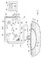
- FIG. 1is a schematic, perspective view of an illustrative system for treating a tissue site on an animal with reduced pressure that involves storing liquids in an inline storage pouch;
- FIG. 3is a schematic, elevation view of an illustrative patient-port interface
- FIG. 4is a schematic, perspective view showing a pouch-facing side of the patient-port interface of FIG. 3 ;
- FIG. 5is a schematic, perspective view showing a first side (opposite the pouch-facing side) of an illustrative embodiment of a device-port interface;
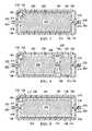
- FIG. 9is a schematic cross section of another illustrative embodiment of the inline storage pouch shown in FIG. 2 taken along line A-A;
- FIG. 10is a schematic cross section of another illustrative embodiment of the inline storage pouch shown in FIG. 2 taken along line A-A;
- FIG. 11is a schematic cross section of another illustrative embodiment of the inline storage pouch shown in FIG. 2 taken along line A-A;
- FIG. 12is a schematic cross section of another illustrative embodiment of the inline storage pouch shown in FIG. 2 taken along line A-A;
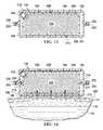
- FIG. 14is a schematic cross section of another illustrative embodiment of the inline storage pouch shown in FIG. 2 taken along line A-A and shown on an animal;
- FIG. 15is a schematic plan view of an illustrative embodiment of an inline storage pouch
- FIG. 16is a schematic, perspective view of, inter alia, a reduced-pressure indicator
- FIG. 17Ais a schematic elevation view of the reduced-pressure indicator of FIG. 12 shown in an extended position
- FIG. 17Bis a schematic elevation view of a portion of the reduced-pressure indicator of FIG. 12 shown in a retracted position;
- FIG. 18is a schematic plan view of an illustrative embodiment of an inline storage pouch
- FIG. 20is a schematic plan view of an illustrative embodiment of an inline storage pouch
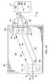
- FIG. 21is a schematic, illustrative flow diagram of steps that may be performed using a microprocessor in an illustrative system for treating a tissue site on an animal with reduced pressure that involves storing liquids in an inline storage pouch;
- FIG. 24is a schematic, exploded perspective view of the inline storage pouch of FIGS. 22-23 ;
- FIG. 25is a schematic elevation view of an illustrative embodiment of a pouch connector shown in FIGS. 21-24 ;
- FIG. 26is a schematic cross-sectional view of the pouch connector of FIG. 25 ;
- FIG. 27is a schematic, perspective view showing primarily a second, tissue-facing side of the pouch connector of FIGS. 25-26 .
- the system 100includes an inline storage pouch 106 .
- the system 100is shown on a human, but the system 100 may be used on any animal 104 , e.g., horse, cow, dog, pig, turtle, etc.
- the system 100includes a wound dressing 108 (or other fluid reception device), the inline storage pouch 106 , and a therapy unit 110 , which includes a reduced-pressure source 112 .
- Liquidsare delivered to the inline storage pouch 106 for storing.
- the liquidsare removed from the animal 104 using reduced pressure.
- the liquidsare from a tissue site 102 , e.g., a wound site, but could also be from an ostomy bag or another source.
- the system 100may allow the user to position the weight of the inline storage pouch 106 and the therapy unit 110 at different locations on the animal. In other words, the weight of the components of the system 100 may be distributed at different locations as suggested in FIG. 1 .
- the inline storage pouch 106may be strapped to a portion of the animal 104 , such as a leg, using straps 107 (or other attachment devices).
- the therapy unit 110may be attached at another location on the animal 104 , e.g., a torso, using straps 111 .
- the inline storage pouch 106is flexible. The flexibility allows the inline storage pouch 106 to conform to a portion of the animal's body thereby enhancing safety and comfort. In addition, the flexible nature of the inline storage pouch 106 allows the inline storage pouch 106 to be stored in a small space. The inline storage pouch 106 is relatively easy to manufacture compared to rigid canisters that have been used to collect liquids. Moreover, when the inline storage pouch 106 is used with non-human animals, the flexible nature may help prevent injury when the animal bumps surfaces or rolls over.
- a wound 103 at tissue site 102is through epidermis 114 and into dermis 116 .
- the wound dressing 108is disposed on the tissue site 102 , e.g., the wound 103 , and is operable to receive fluids from the tissue site 102 .
- the wound dressing 108may be any type of dressing for receiving fluids from the patient, but is shown as a dressing with a wound-interface manifold 118 and a drape 120 .
- the wound dressing 108may be any device that collects liquids whether a wound is involved or not.
- the wound dressing 108may be a device for removing liquids from an ostomy bag.
- the wound dressing 108is for removing liquids from a wound 103 .
- Fluids, including liquids, from the tissue site 102are delivered through a reduced-pressure interface 122 to a first multi-lumen conduit 124 .
- the first multi-lumen conduit 124is fluidly coupled to the inline storage pouch 106 .
- the reduced-pressure interface 122may be any device capable of accomplishing at least two functions: (1) fluidly coupling the reduced-pressure lumen 130 to the wound dressing 108 to deliver reduced pressure to the desired area and (2) fluidly coupling the sensing lumen 132 to a sealed space created by the drape 120 .
- the first multi-lumen conduit 124is coupled to the inline storage pouch 106 at a first port 133 .
- the first port 133is formed on (including coupled to) the flexible pouch body 138 .
- the flexible pouch body 138has a first side 139 and a second, animal-facing side 141 .
- the first port 133may be formed on either side 139 , 141 , but is shown on the second, animal-facing side 141 .
- the first port 133may be any device that accomplishes at least a couple functions. First, the first port 133 fluidly couples the reduced-pressure lumen 130 of the first multi-lumen conduit 124 to an interior portion 136 (see FIG. 7 ) of a flexible pouch body 138 . Second, the first port 133 fluidly couples the sensing lumen 132 of the first multi-lumen conduit 124 to a first bypass conduit 140 . The first bypass conduit 140 is formed in the interior portion 136 of the flexible pouch body 138 and yet is fluidly isolated from the interior portion 136 . For example, without, limitation, the first port 133 may be a patient-port interface 134 .
- the patient-port interface 134includes a patient-port body 142 having a first side 144 and a second, pouch-facing side 146 .
- the patient-port body 142also includes a first hollow attachment connector 148 sized and configured for mating with the at least one reduced pressure lumen 130 of the first multi-lumen conduit 124 .
- the first hollow attachment connector 148is fluidly coupled to a first fluid outlet 150 formed on the patient-port body 142 .
- the patient-port interface 134may be coupled to either the first 139 or second, animal-facing side 141 of the flexible pouch body 138 .
- the patient-port body 142also includes a second hollow attachment connector 152 sized and configured for mating with the at least one sensing lumen 132 of the first multi-lumen conduit 124 .
- the second hollow attachment connector 152is fluidly coupled to a first pressure-sensing connector 154 on the second, pouch-facing side 146 .
- the first pressure-sensing connector 154is fluidly coupled to a first end of the first bypass conduit 140 .
- the first pressure-sensing connector 154may be substantially parallel to the surface of the second, pouch-facing side 146 and may include a conduit-channel 156 .
- a first plurality of offsets 158is formed on the second, pouch-facing side 146 of the patient-port body 142 for providing flow space 160 .
- the flow space 160assures space for reduced pressure to move fluids. In other words, the flow space 160 provides space for the fluids to expand and manifold into a fluid storage material 204 or other portion of the interior portion 136 .
- fluidsare moved via pressure differential from the first fluid outlet 150 across the interior portion 136 of the inline storage pouch 106 to a second port 162 as suggested by arrows 163 .
- the fluidis distributed throughout the interior portion 136 as the reduced pressure draws from the second port 162 .
- the second port 162fluidly couples the interior portion 136 to a second reduced-pressure lumen 164 of a second multi-lumen conduit 166 .
- the second port 162is shown coupled to the first side 139 of the flexible pouch body 138 .
- the second port 162may also be formed on the second, animal-facing side 141 .
- the first port 133 and second port 162are on opposite sides 139 , 141 of the flexible pouch body 138 .
- the second reduced-pressure lumen 164is fluidly coupled to the reduced-pressure source 112 of the therapy unit 110 .
- the first bypass conduit 140delivers fluid from the first port 133 to the second port 162 .
- the first bypass conduit 140is fluidly isolated from fluids in the interior portion 136 of the flexible pouch body 138 .
- the second port 162fluidly couples the first bypass conduit 140 to a second sensing lumen 168 of the second multi-lumen conduit 166 .
- the second sensing lumen 168may be fluidly coupled to a pressure sensing unit 170 of the therapy unit 110 .
- the second port 162may be any device that accomplishes at least two functions. First, the second port 162 fluidly couples the first bypass conduit 140 to the second sensing lumen 168 . Second, the second port 162 fluid couples the second reduced-pressure lumen 164 to the interior portion 136 of the flexible pouch body 138 . In one illustrative embodiment, the second port 162 is a device-port interface 172 .
- the device-port interface 172includes a device-port body 174 having a first side 176 and a second, pouch-facing side 178 .
- the device-port body 174includes a third hollow attachment connector 180 sized and configured for mating with the second reduced-pressure lumen 164 .
- the third hollow attachment connector 180is fluidly coupled to a fluid inlet 182 .
- the third hollow attachment connector 180is formed on (including coupled to) the device-port body 174 .
- the device-port body 174also includes a fourth hollow attachment connector 184 sized and configured for mating with the second sensing lumen 168 of the second multi-lumen conduit 166 .
- a second pressure-sensing connector 186is fluidly coupled to the fourth hollow attachment connector 184 .
- the second pressure-sensing connector 186is fluidly coupled to a second end of the first bypass conduit 140 .
- the second pressure-sensing connector 186may be substantially parallel to the surface of the second, pouch-facing side 178 and may include a conduit-channel 187 .
- the device-port interface 172may further include an offset 188 formed on the second, pouch-facing side 178 of the device-port body 174 for providing a filter space 192 for one or more hydrophobic filters with bacterial filtering properties.
- the offset 188is a wall 190 that forms the filter space 192 .
- a filter 194 or multiple filtersare disposed within the filter space 192 .
- the filter 194may be any material that prevents liquids from entering the fluid inlet 182 .
- the filter 194includes a hydrophobic filter member, a manifolding material, and another hydrophobic filter member or any permutation thereof or functional device to prevent liquids from entering the fluid inlet 182 .
- the filter 194 or filtersare hydrophobic, bacterial filtering membranes that are located to prevent fluids and bacteria from progressing towards the therapy unit 110 .
- the filter membranemay be a GORE® MMT314 material available from W. L. Gore & Associates, Inc., Newark, Del.
- the one or more filters 194are displaced from the base of the device-port interface 172 by castilated surface features (not explicitly shown) or other surface features designed to provide an open area of filter for flow.
- a charcoal filtermay also be included to remove odor.
- a porous polymer, gel-blocking filtermay be included in the second reduced-pressure lumen 164 .
- the flexible pouch body 138 of the inline storage pouch 106is formed with a first wall 196 and a second wall 198 .
- the two walls 196 , 198are coupled or formed as a single unit to form the flexible pouch body 138 .
- the flexible pouch body 138has the interior portion 136 formed between the walls 196 , 198 .
- the first wall 196 and the second wall 198are coupled by an attachment 200 at a peripheral edge 202 of the walls 196 , 198 .
- the attachment 200may be formed using any known technique, including without limitation welding (e.g., ultrasonic or RF welding), bonding, adhesives, cements, stitching, staples, or another coupling device.
- the first wall 196 and second wall 198may be formed from any flexible, liquid-impermeable material.
- the first wall 196 and second wall 198may be formed from one or more of the following: natural rubbers, polyisoprene, styrene butadiene rubber, chloroprene rubber, polybutadiene, nitrile rubber, butyl rubber, ethylene propylene rubber, ethylene propylene diene monomer, chlorosulfonated polyethylene, polysulfide rubber, polyurethane (PU), EVA film, co-polyester, silicones, silicone drape, a 3M Tegaderm® drape, or a polyurethane (PU) drape such as one available from Avery Dennison Corporation of Pasadena, Calif., or other appropriate material.
- natural rubberspolyisoprene, styrene butadiene rubber, chloroprene rubber, polybutadiene, nitrile rubber, butyl rubber, ethylene propylene rubber,
- the inline storage pouch 106may be sized to accommodate the quantity of liquid anticipated for a typical treatment time.
- the interior portion 136has a volume greater than 180 milliliters and less than 500 milliliters, but numerous sizes may be used.
- the interior portion 136 formed by the flexible pouch body 138may be filled at least in part by the fluid storage material 204 .
- the storage material 204may be formed from any material that receives fluids, including liquids; retains the fluids; and allows reduced pressure to be transmitted.
- the fluid storage material 204comprises an absorbent member 206 , a first wicking member 208 , and a second wicking material 210 .
- the absorbent member 206may be any material that retains liquids and may comprise one or more of the following: Luquafleece® material, BASF 402c, Technical Absorbents 2317 available from Technical Absorbents (www.techabsorbents.com), sodium polyacrylate super absorbers, cellulosics (carboxy methyl cellulose and salts such as sodium CMC), or alginates.
- the first wicking member 208 and second wicking member 210may be formed from one or more of the following: non-woven fabrics such as Libeltex TDL2 or other non-wovens from LIBELTEX bvba of Belgium (www.libeltex.com), woven fabrics including 3D spacer fabrics and Textiles (Baltex, Ilkeston, Derby, UK), open-cell foam, or sintered polymers.
- the wicking members 208 , 210may be formed by multiple layers of wicking materials that have been stacked or layered.
- the first wicking member 208 and the second wicking member 210may be disposed adjacent to one another at least at their peripheral edges 216 and coupled with an attachment 214 (analogous to attachment 200 as previously described).
- the wicking members 208 , 210surround the absorbent member 206 .
- the peripheral edges 216form overlapping portions and are held in contact with one another to provide a fluid coupling between the wicking members 208 , 210 .
- the wicking members 208 , 210may thus be in fluid communication with each other.
- the wicking members 208 , 210allow fluid flow between the wicking members 208 , 210 and along the wicking members 208 , 210 at times when the flow of fluid in the absorbent member 206 is inhibited or blocked.
- the first bypass conduit 140comprises a tube 218 , but it could also be a web member 212 attached against a portion of wall 196 ( FIG. 11 ), or any device that provides a path to move fluid through the interior portion 136 while remaining fluidly isolated from the interior portion 136 .
- FIGS. 2 and 8another illustrative inline storage pouch 106 is presented.
- the inline storage pouch 106is analogous in most respects to the inline storage pouch 106 of FIGS. 1, 2, and 7 , and accordingly, some parts are labeled but not further described here.
- the primary differenceis that the flexible pouch body 138 is formed with one or more optional fluid-communication buttons 207 .
- Each fluid communication-button 207may be formed by creating an aperture 209 in the absorbent member 206 .
- the first wicking member 208 and second wicking member 210are brought into contact in the aperture 209 , and first wicking member 208 and second wicking member 210 are attached at or near the point of contact.
- the wicking members 208 , 210are attached using one or more attachments 211 (analogous to 214 ). This embodiment may be particularly useful in minimizing pressure drop across the inline storage pouch 106 when the wicking members 208 , 210 are formed from a non-woven manifolding material.
- the fluid-communication buttons 207enhance the degree of fluid communication between the first wicking member 208 and second wicking member 210 .
- FIGS. 2 and 9another illustrative inline storage pouch 106 is presented.
- the inline storage pouch 106is analogous in most respects to the inline storage pouch 106 of FIGS. 1, 2, and 7-8 , and accordingly, some parts are labeled but not further described here.
- the primary difference in this embodimentis that a first plurality of offsets 215 has been formed and disposed between the first wall 196 and the fluid storage material 204 .
- the first plurality of offsets 215may be positioned between the first wall 196 and the first wicking member 208 .
- the first plurality of offsets 215may include a first base 217 .
- the inline storage pouch 106may also include a second plurality of offsets 219 .
- the second plurality of offsets 219may be disposed between the second wall 198 and the fluid storage material 204 .
- the second plurality of offsets 219may be positioned between the second wicking member 210 and the second wall 198 .
- the second plurality of offsets 219may include a second base 221 .
- the offsets 215 , 219create additional space for the flow of reduced pressure within the interior portion 136 .
- the inline storage pouch 106 of FIG. 9may be used with a high-vapor-transfer-rate material as described in connection with FIG. 14 below, but typically the first base 217 and second base 221 would be perforated.
- the offsets 215 , 219may formed from any rigid or semi-rigid material approved for use in a body.
- the offsets 215 , 219are typically formed from a non-absorbent material.
- the offsets 215 , 219may be formed, for example, from a high-impact polystyrene and may be vacuumed formed to a desired shape (e.g., cylinder, tube, cone, or other shape) and sized as desired for the chamber or interior space.
- the offsets 215 , 219 with their respective bases 217 , 221are flexible and reduced pressure can pass in between the offsets, i.e., through the bases 217 , 221 , which may permeable or perforated.
- the offsets 215 , 219facilitate open flow for reduced pressure transmission under compression.
- the offsets 215 , 219may vary in quantity and pattern or shape and size but should allow pressure to be transmitted and the inline storage pouch 106 to remain flexible.
- the offsets 215 , 219may be any shape or size that provides clearance of at least 1 mm.
- the inline storage pouch 106is analogous in most respects to the inline storage pouch 106 of FIGS. 1, 2, and 7-9 , and accordingly, some parts are labeled but not further described here.
- the primary difference in this embodimentis that the inline storage pouch 106 includes a first plurality of offsets 215 and a third wicking member 223 .
- the first plurality of offsets 215are disposed between the first wall 196 and the fluid storage material 204 to create additional flow space for reduced pressure to flow.
- the third wicking member 223may be disposed between the second wall 198 and the fluid storage material 204 .
- the third wicking member 223may be formed from the same materials as the first wicking member 208 .
- the third wicking member 223may be disposed between the second wall 198 and the second wicking member 210 .
- the third wicking member 223provides additional manifolding material for fluid flow.
- additional wicking membersmay be added in addition to the third wicking member 223 .
- one or more additional wicking membersmay be added between the first wall 196 and the absorbent member 206 .
- a first bypass conduit 140may be formed by the web member 212 attached against the portion of wall 196 .
- the web member 212may be formed from the same material as the first wall 196 .
- the first bypass conduit 140includes a conduit-manifold material 213 .
- the conduit-manifold material 213may be any material that is sufficient to prevent the first bypass conduit 140 from collapsing under reduced pressure.
- a first bypass conduit 140is formed by using a third wall 199 that together with the first wall 196 forms the first bypass conduit 140 .
- the third wall 199may be formed from the same materials as the first wall 196 .
- the first bypass conduit 140may be at least partially filled with a conduit-manifold material 213 . This embodiment allows the first bypass conduit 140 to extend the width of the flexible pouch body 138 .
- the fluid storage material 204comprises an absorbent member 206 surrounded by a wicking member 208 that has been coated, extruded, or otherwise directly applied onto the exterior of the absorbent member 206 .
- the inline storage pouch 106is analogous in most respects to the inline storage pouch 106 of FIGS. 1, 2, 7-13 , and accordingly, some parts are labeled but not further described here.
- the first wall 196 or second wall 198are formed from a high-vapor-transfer-rate material.
- the high-moisture-vapor-transfer-rate (“MVTR”) materialmay be formed from any material that allows vapor to egress but not liquids.
- “Moisture Vapor Transmission Rate” or “MVTR”represents the amount of moisture that can pass through a material in a given period of time.
- the high-moisture-vapor-transfer-rate materialtypically has a moisture vapor transmission rate greater than 300 g/m 2 /24 hours and more typically 1000 g/m 2 /24 hours or more.
- the high-moisture-vapor-transfer-rate materialallows vapor to egress or diffuse from the interior portion 136 , but not liquids.
- the high-moisture-vapor-transfer-rate materialmay comprise one or more of the following: hydrophilic polyurethane, cellulosics, hydrophilic polyamides, an INSPIRETM 2301 material from Exopack Advanced Coatings of Wrexham, United Kingdom; a thin, uncoated polymer drape; or polyvinyl alcohol, polyvinyl pyrrolidone, hydrophilic acrylics, hydrophilic silicone elastomers and copolymers of these.
- the INSPIRETM 2301 illustrative filmhas an MVTR (inverted cup technique) of 14500-14600 g/m 2 /24 hours. See www.exopackadvancedcoatings.com.
- the high-moisture-vapor-transfer-rate materialsmay have various thicknesses, such as 10 to 40 microns ( ⁇ m), e.g., 15, 20, 25, 30, 35, 40 microns (inclusive of all numbers in the stated range).
- the inline storage pouch 106has a flexible pouch body 138 with an interior portion 136 .
- the interior portion 136is at least partially filled with a storage material 204 that may be formed with a first wicking member 208 , an absorbent member 206 , and a second wicking member 210 .
- the wicking members 208 , 210may be coupled at their peripheral edges 216 by an attachment 214 (analogous to attachment 200 ).
- the inline storage pouch 106 of FIG. 14is shown on the animal's epidermis 114 . Some clearance between the epidermis 114 and inline storage pouch 106 may be provided by hair 220 . Moisture from the animal's epidermis 114 may ingress into the interior portion 136 through the second wall 198 , which is formed from a high-moisture-vapor-transfer-rate material. The ingress is due to a moisture imbalance. The moisture enters the second wicking member 210 . In addition, moisture may egress the interior portion 136 through the first wall 196 , which may also comprise a high-moisture-vapor-transfer-rate material.
- a third wicking membermay be added on an exterior of the second wall 198 to wick moisture away from the animal's epidermis 114 .
- the wound dressing 108is applied to the tissue site 102 .
- the inline storage pouch 106is positioned at a desired location on the animal 104 or near the animal 104 depending on the application. If applied on the animal 104 , the inline storage pouch 106 may be strapped, tapped, or otherwise secured to the animal 104 .
- the inline storage pouch 106is fluidly coupled to the wound dressing 108 to provide reduced pressure to the wound dressing 108 and to receive wound-site pressure from the tissue site 102 .
- the therapy unit 110may also be positioned on or near the animal 104 .
- the therapy unit 110is fluidly coupled to the inline storage pouch 106 .
- the therapy unit 110provides reduced pressure to the inline storage pouch 106 and receives the wound-site pressure for determining pressure a the tissue site 102 .
- the therapy unit 110may control the therapy, analyze any blockages, and provide alerts as described further below.
- fluidsare pulled from the animal 104 into the inline storage pouch 106 .
- the fluidenters the first port 133 and is pulled toward the second port 162 .
- the fluidis distributed throughout the interior portion 136 and particularly in the fluid storage material 204 .
- gasestypically air—continue to move or to manifold through the interior portion 136 .
- the gasesmay move through the interior portion 136 primarily through the wicking members 208 , 210 when included or through space created by the third wicking member 223 or by the offsets 215 , 219 .
- baffles or internal wallsmay be added in the interior portion 136 to cause the fluid flow to take a tortuous path between the ports 133 , 162 .
- the flexible pouch body 138includes a first port 133 having a first reduced-pressure indicator 222 and a second port 162 having a second reduced-pressure indicator 224 .
- the ports 133 , 162are shown on the same side of the flexible pouch body 138 , but it should be understood that one or both of the ports 133 , 162 may be located on the opposite side as shown in other figures herein.
- the first reduced-pressure indicator 222may be fluidly coupled to the interior portion 136 of the flexible pouch body 138 proximate to the first port 133 or as an aspect of the first port 133 .
- the first reduced-pressure indicator 222may be included as an aspect of the patient-port interface 134 as shown in FIG. 16 .
- the first reduced-pressure indicator 222provides a visual indication of whether or not the first reduced-pressure indicator 222 experiences a reduced pressure greater than a first threshold.
- the second reduced-pressure indicator 224may be fluidly coupled to the interior portion 136 of the flexible pouch body 138 proximate to the second port 162 and may be part of the device-port interface 172 .
- the second reduced-pressure indicator 224provides a visual indication of whether or not the second port 162 experiences a reduced pressure greater than a second threshold, which may be the same as the first threshold.
- the reduced-pressure indicators 222 , 224are analogous to one another.
- the reduced-pressure indicators 222 , 224may each be formed with a moving member 226 adapted to move when reduced pressure exceeds a threshold pressure (P t ).
- the reduced-pressure indicators 222 , 224have a visual indicator 228 associated with the moving member 226 .
- the visual indicator 228is an indicator member 230 or portion, such as a disk-shaped member 232 (or button), or a member of any shape that signifies a changed state with respect to pressure.
- the moving member 226may be a collapsible wall 234 that has a first end 236 and a second end 238 .
- the first end 236may be coupled to the indicator member 230 .
- the second end 238may be coupled to a base 240 .
- the collapsible wall 234 and indicator member 230form a pressure vessel with base 240 .
- the collapsible wall 234may have a convex interior surface and may include baffles or other features to assist in collapsing at the threshold pressure.
- the collapsible wall 234collapses (alone or with movement in the base 240 ) and causes the visual indicator 228 to go from a first position, e.g., an extended position, to a second position, e.g., a retracted position, as shown in FIGS. 17A and 17B , respectively.
- the collapsible walls 234 of the reduced-pressure indicatormay be sized and shaped to collapse or move the indicator member 230 to be substantially flush or against the base 240 when the threshold reduced pressure (P t ) is achieved.
- the collapsible wall 234returns to the extended position. In other words, the reduced pressure causes the reduced-pressure indicator to collapse as long as there is adequate reduced pressure.
- the reduced-pressure indicator 222 , 224 , interfaces 134 , 172 , and base 240may be formed from a medical-grade, soft polymer or other pliable material, such as one or more of the following: polyurethane, polyethylene, polyvinyl chloride (PVC), fluorosilicone, ethylene-propylene, DEHP-free PVC, or other material.
- the componentsmay be cast, or extruded, and may be formed as an integral unit.
- the usermay analyze the situation using the reduced-pressure indicators 222 , 224 . If pressure is being received at the first reduced-pressure indicator 222 , i.e., the indicator member 230 shows that the collapsible wall 234 is still collapsed, then a problem exists between the tissue site 102 and the inline storage pouch 106 .
- the pressure sensing unit 170may be fluidly coupled to the second sensing lumen 168 and separately to the first pouch-pressure-sensing conduit 250 .
- therapy unit 110which also may include a microprocessor 253 , is able to determine the pressure at the tissue site 102 and also in the interior portion 136 of the flexible pouch body 138 proximate to the first port 133 .
- the therapy unit 110may check the pressure proximate the first port 133 (in the first pressure-sensing pad 248 ) proactively or if inadequate pressure, i.e., below a threshold, is determined at the tissue site 102 .
- the therapy unit 110may provide an alert that a blockage exists between the inline storage pouch 106 and the tissue site 102 . If inadequate pressure exists at the first pressure-sensing pad 248 , the therapy unit 110 may signal that the inline storage pouch 106 is full or block exists between the inline storage pouch 106 and the reduced-pressure source 112 .
- FIG. 19another illustrative embodiment of an inline storage pouch 106 is presented.
- the inline storage pouch 106is analogous in most respects to the inline storage pouch 106 of FIGS. 1, 2, 7-14, and 18 , and accordingly, some parts are labeled but not further described here.
- components referenced but not explicitly shownare analogous to those previously presented.
- a second pressure-sensing pad 252has been coupled proximate to the second port 162 .
- the second pressure-sensing pad 252includes a filter element (not explicitly shown) that becomes occluded when saturated with liquid.
- the second pressure-sensing pad 252may be fluidly coupled to the interior portion 136 of the flexible pouch body 138 proximate to the second port 162 .
- the second multi-lumen conduit 166further includes a first pouch-pressure-sensing conduit 250 fluidly coupled to the pressure sensing unit 170 of the therapy unit 110 .
- the therapy unit 110may signal that the inline storage pouch 106 is full.
- FIG. 20another illustrative embodiment of an inline storage pouch 106 is presented.
- the inline storage pouch 106is analogous in most respects to the inline storage pouch 106 of FIGS. 1, 2, 7-14, and 18-19 and accordingly, some parts are labeled but not further described here.
- components referenced but not explicitly shownare analogous to those previously presented.
- the inline storage pouch 106includes the second bypass conduit 242 as in FIG. 18 fluidly coupled to the interior portion 136 of the flexible pouch body 138 proximate to the first port 133 .
- the second bypass conduit 242may also be fluidly coupled to the first pouch-pressure-sensing conduit 250 .
- the inline storage pouch 106also includes a second pressure-sensing pad 252 like in FIG. 19 fluidly coupled to the interior portion 136 of the flexible pouch body 138 proximate to the second port 162 and to a second pouch-pressure-sensing conduit 254 .
- the second pouch-pressure-sensing conduit 254may be fluidly coupled to the second pressure-sensing pad 252 and to a therapy unit 110 .
- the portion of the system 100 shown in FIG. 20includes the therapy unit 110 .
- the therapy unit 110includes the reduced-pressure source 112 and pressure sensing unit 170 .
- the pressure sensing unit 170includes a first pressure sensing device 258 , a second pressure sensing device 260 , and a third pressure sensing device 262 .
- the first pressure sensing device 258is fluidly coupled to the pressure-assessment conduit 128 of the reduced-pressure interface 122 for determining a wound-site pressure, i.e., the pressure at the tissue site 102 .
- the second pressure sensing device 260may be fluidly coupled to the first pressure-sensing pad 248 for determining pressure proximate the first port 133 .
- the third pressure sensing device 262may be fluidly coupled to the second pressure-sensing pad 252 for determining pressure at the second port 162 .
- the first pressure sensing device 258may be fluidly coupled to the second sensing lumen 168 of the second multi-lumen conduit 166 .
- the second sensing lumen 168may also be fluidly coupled to the first bypass conduit 140 and to the sensing lumen 132 of the first multi-lumen conduit 124 .
- the sensing lumen 132may be fluidly coupled to the pressure-assessment conduit 128 .
- the second pressure sensing device 260may be fluidly coupled to the first pouch-pressure-sensing conduit 250 .
- the first pouch-pressure-sensing conduit 250may be fluidly coupled to the second bypass conduit 242 .
- the second bypass conduit 242may be fluidly coupled to first pressure-sensing pad 248 proximate to the first port 133 .
- the third pressure sensing device 262may be fluidly coupled to the second pouch-pressure-sensing conduit 254 .
- the second pouch-pressure-sensing conduit 254may be fluidly coupled to the second pressure-
- the therapy unit 110may pinpoint the location (or at least give an area) of blockage or may indicate that the inline storage pouch 106 is full.
- FIG. 21one possible logic flow for operation of the system in FIG. 20 is presented.
- the processbegins at step 264 and the first interrogatory box 266 inquires as to whether or not the desired pressure is being realized at the tissue site 102 .
- the microprocessor 253may determine this by comparing the pressure determined by the first pressure sensing device 258 with a selected pressure threshold. If the interrogatory is affirmative, the process continues back along path 268 . If not, the microprocessor 253 may activate the reduced-pressure source 112 at step 270 to provide reduced pressure. Optionally a certain amount of time may be required before moving beyond step 270 and the interrogatory box 266 may be revisited.
- the interrogatory box 272With inadequate pressure existing, the interrogatory box 272 is reached and calls for the pressure to be checked at the second port 162 by the second pressure-sensing pad 252 .
- the microprocessor 253receives the pressure from the third pressure sensing device 262 . If there is not a reduced pressure greater (i.e., more reduced with respect to absolute pressure) than a threshold reduced pressure at the second port 162 , a flag is raised at step 274 that a blockage exists between the reduced-pressure source 112 and the inline storage pouch 106 . If adequate pressure is at the second port 162 , the problem must be elsewhere and the process continues to interrogatory box 276 . Interrogatory box 276 inquires as to the pressure at the first port 133 . The microprocessor 253 receives the pressure from the second pressure sensing device 260 . If the pressure is inadequate, step 278 is reached an alert posted that the pouch is full or blocked.
- interrogatory box 280If pressure exists at the first port 133 but not at the tissue site 102 , which is the question of interrogatory box 280 , an alert is issued at step 282 that a blockage exists between the inline storage pouch 106 and the wound dressing 108 . If pressure exists at the tissue site 102 , but is not adequate, another round of analysis may occur as suggested by path 284 . A counter or chronograph may be included to limit the number of times through the cycle. Thus, after a maximum count or maximum time, an error flag may be provided. If adequate pressure is now realized at the tissue site 102 , the answer to interrogatory box 286 is positive and the process continues from interrogatory box 286 to interrogatory box 266 . This is one illustrative process and many others may be used. Those skilled in the art will understand various ways to implement the functionality in hardware or software. In addition, portions of this process may be used separately.
- the inline storage pouch 300is analogous in many respects to the inline storage pouch 106 of the previous figures.
- the inline storage pouch 300includes a pouch connector 302 .
- the inline storage pouch 300may be used as part of a system, e.g., system 100 of FIG. 1 , to treat a tissue site on an animal.
- the inline storage pouch 300includes a flexible pouch body 304 .
- the flexible pouch body 304is formed with a first wall 306 , a second wall 308 , and a partitioning wall 310 .
- the walls 306 and 308form an interior portion partitioned by the partitioning wall 310 to form a first chamber 312 and a second chamber 314 .
- the wallsmay be formed from any liquid-impermeable, flexible material, for example, polyurethane or any of those materials previously mentioned for the wall 196 .
- the flexible pouch body 304has a proximal end 316 and a distal end 318 .
- a longitudinal axisextends generally between the proximal end 316 and the distal end 318 .
- a first manifolding material 320is disposed within the first chamber 312 .
- the first manifolding material 320may be formed from the same materials as conduit-manifold material 213 , e.g., BASF Luquafleece 402C or an analogous material.
- a fluid storage material 321is disposed within the second chamber 314 .
- the fluid storage material 321may be surrounded by a wicking material 322 .
- the wicking material 322may be one or more of the materials mentioned for wicking material 208 , e.g., Libeltex TDL2 80 gsm or an analogous material.
- the wicking material 322may be two separate pieces of material that are welded or otherwise coupled at their peripheral edges 324 to form a “tea bag” like arrangement containing the fluid storage material 321 .
- the wicking material 322may include one or more apertures, e.g., aperture 323 to facilitate a portion of the pouch connector 302 to extend therethrough.
- a second manifolding material 326may also be disposed within the second chamber 314 .
- the second manifolding material 326may be the same as first manifolding material 320 , but in another embodiment is shown as a plastic layer 328 having offsets 330 .
- the offsets 330may be in the range 0.25-0.5 mils from a base of the plastic layer.
- the offsets 330may be formed by injection molding the plastic layer 328 with offsets or vacuum forming.
- the offsets 330may be ridges a shown, pegs, or any spacer.
- the second manifolding material 326functions to ensure that the exudate collecting area (chamber) remains open.
- the offsets 330may be the same or analogous to offsets 215 , 219 .
- the pouch connector 302is coupled to the flexible pouch body 304 proximate the proximal end 316 but could be placed at other locations.
- the pouch connector 302receives fluids from the animal and delivers the fluids to the second chamber 314 .
- the pouch connector 302also fluidly couples reduced pressure received from a reduced-pressure source to the first chamber 312 .
- the pouch connector 302includes a connector body 332 formed with an exudate chamber 334 .
- the exudate chamber 334has an intake port 336 for receiving the fluids from the animal and an outlet 338 for discharging the fluids from the animal.
- the intake port 336may comprise a first tube connector 337 for coupling to a first conduit 339 .
- the first tube connector 337may include a tube lock 372 .
- the first conduit 339may be a multi-lumen conduit having a first reduced-pressure lumen 341 and a first pressure-sensing lumen 343 .
- a displacement conduit 340is fluidly coupled to the outlet port 338 and the second chamber 314 for delivering the fluids from the exudate chamber 334 to the second chamber 314 .
- the displacement conduit 340may be a tube or a hollow offset that is open or the like.
- the connector body 332is also formed with a reduced-pressure chamber 342 .
- the exudate chamber 334 and reduced-pressure chamber 342are fluidly isolated from each other within the pouch connector 302 by a portion of the connector body 332 .
- the reduced-pressure chamber 342has an intake port 344 for receiving fluids from the first chamber 312 and an outlet port 346 for discharging fluids.
- the outlet port 346 of the reduced-pressure chamber 342is for receiving the reduced pressure from the reduced-pressure source.
- the outlet port 346may comprise a tube connector 348 that couples to a second conduit 350 that is fluidly coupled to a reduced-pressure unit or source, e.g., therapy unit 110 in FIG. 2 .
- the second conduit 350may be a multi-lumen conduit that has a reduced-pressure lumen for delivering reduced pressure ultimately to the first chamber and a second pressure-sensing lumen for receiving reduced pressure ultimately from the first reduced-pressure sensing lumen via the pouch connector 302 .
- the connector body 332may also includes a plurality of offsets 352 on the connector body 332 proximate to the intake port 344 of the reduced-pressure chamber 342 .
- the offsets 352may be in the range of 0.5 mils to several mils. The offsets 352 function to ensure fluid flow proximate to the intake port 344 in the first chamber 312 .
- the intake port 336 of the exudate chamber 334may be substantially parallel to the outlet port 346 of the reduced-pressure chamber 342 .
- the flexible pouch body 304has a longitudinal axis (substantially parallel to section line 23 - 23 in FIG. 22 ) that may be substantially parallel to the axis of the intake port 336 of the exudate chamber 334 and may be perpendicular to the axis of the displacement conduit 340 .
- the partitioning wall 310 of the flexible pouch body 304is formed with an exudate aperture 354 for receiving a portion of the pouch connector 302 , e.g., the displacement conduit 340 , into the second chamber 314 .
- the partitioning wall 310may be coupled to the displacement conduit 340 to form a fluid seal to prevent fluid from entering the first chamber 312 from the second chamber at that point.
- the couplingmay be formed using any coupling technique, e.g., glue, epoxy, UV glue, welds, bonds, or other techniques.
- a first connector aperture 355may be formed in the first manifold material 320 on the proximal end 316 .
- the exudate aperture 354is formed on the proximal end of the partitioning wall 310 and is sized and configured to align with exudate aperture 354 .
- a return aperture 356is formed at the other end, the distal end of the partitioning wall 310 for allowing fluid flow from the second chamber 314 into the first chamber 312 . Stated another way, reduced pressure may flow from the first chamber 312 through the return aperture 356 to the second chamber 314 .
- a primary filter 358e.g., a hydrophobic filter, covers the return aperture 356 to inhibit liquids from entering the first chamber 312 .
- a secondary filter 360may also be included that covers the fluid path of the return aperture 356 .
- a piece of manifolding material 362may be used to separate the primary filter 358 and the secondary filter 360 .
- An apron of polyurethane 364 or other materialmay be used to secure secondary filter 360 and the manifolding material 362 to a first side of the partitioning wall 310 .
- a charcoal filter or other odor filtermay be added as well.
- a second connector aperture 366may be formed in the first wall 306 to allow a portion of the pouch connector 302 to extend through the second connector aperture 366 .
- the second connector aperture 366may facilitate coupling a portion of the first wall 306 to a base portion 368 of the pouch connector 302 .
- the fluid storage material 321may have one or more apertures 370 .
- the apertures 370facilitate coupling of a portion of the partitioning wall 310 to the second wall 314 at locations between the proximal and distal ends. While not explicitly shown, apertures in the wicking material 322 may be formed that align with the apertures 370 .
- the pressure-sensing lumen 343 of first conduit 339is fluidly coupled to a pressure-sensing channel 345 at a first end 347 .
- the pressure-sensing channel 345is formed in the connector body 332 of the pouch connector 302 .
- the pressure-sensing channel 345allows a fluid to be communicated through the pouch connector 302 .
- a second end 349 of the pressure-sensing channel 345is fluidly coupled to a pressure-sensing lumen (not explicitly shown) in the second conduit 350 that is fluidly coupled to a reduced-pressure unit, e.g., therapy unit 110 in FIG. 2 , that thereby monitors the pressure at the tissue site on the animal.
- a reduced-pressure unite.g., therapy unit 110 in FIG. 2
- bypass conduitshown in one embodiment, e.g., 140 in FIG. 7 , may be used in FIG. 11 or vice versa.
Landscapes
- Health & Medical Sciences (AREA)
- Heart & Thoracic Surgery (AREA)
- Hematology (AREA)
- Engineering & Computer Science (AREA)
- Anesthesiology (AREA)
- Biomedical Technology (AREA)
- Life Sciences & Earth Sciences (AREA)
- Animal Behavior & Ethology (AREA)
- General Health & Medical Sciences (AREA)
- Public Health (AREA)
- Veterinary Medicine (AREA)
- Vascular Medicine (AREA)
- Otolaryngology (AREA)
- External Artificial Organs (AREA)
- Media Introduction/Drainage Providing Device (AREA)
Abstract
Description
Claims (26)
Priority Applications (3)
| Application Number | Priority Date | Filing Date | Title |
|---|---|---|---|
| US13/442,519US9433712B2 (en) | 2011-08-31 | 2012-04-09 | Inline storage pouches for use with body fluids |
| US15/220,017US10532194B2 (en) | 2011-08-31 | 2016-07-26 | Inline storage pouches for use with body fluids |
| US16/705,493US20200108235A1 (en) | 2011-08-31 | 2019-12-06 | Inline storage pouches for use with body fluids |
Applications Claiming Priority (3)
| Application Number | Priority Date | Filing Date | Title |
|---|---|---|---|
| US201161529709P | 2011-08-31 | 2011-08-31 | |
| US201161543558P | 2011-10-05 | 2011-10-05 | |
| US13/442,519US9433712B2 (en) | 2011-08-31 | 2012-04-09 | Inline storage pouches for use with body fluids |
Related Child Applications (1)
| Application Number | Title | Priority Date | Filing Date |
|---|---|---|---|
| US15/220,017DivisionUS10532194B2 (en) | 2011-08-31 | 2016-07-26 | Inline storage pouches for use with body fluids |
Publications (2)
| Publication Number | Publication Date |
|---|---|
| US20130053797A1 US20130053797A1 (en) | 2013-02-28 |
| US9433712B2true US9433712B2 (en) | 2016-09-06 |
Family
ID=45952671
Family Applications (3)
| Application Number | Title | Priority Date | Filing Date |
|---|---|---|---|
| US13/442,519Expired - Fee RelatedUS9433712B2 (en) | 2011-08-31 | 2012-04-09 | Inline storage pouches for use with body fluids |
| US15/220,017Expired - Fee RelatedUS10532194B2 (en) | 2011-08-31 | 2016-07-26 | Inline storage pouches for use with body fluids |
| US16/705,493AbandonedUS20200108235A1 (en) | 2011-08-31 | 2019-12-06 | Inline storage pouches for use with body fluids |
Family Applications After (2)
| Application Number | Title | Priority Date | Filing Date |
|---|---|---|---|
| US15/220,017Expired - Fee RelatedUS10532194B2 (en) | 2011-08-31 | 2016-07-26 | Inline storage pouches for use with body fluids |
| US16/705,493AbandonedUS20200108235A1 (en) | 2011-08-31 | 2019-12-06 | Inline storage pouches for use with body fluids |
Country Status (7)
| Country | Link |
|---|---|
| US (3) | US9433712B2 (en) |
| EP (2) | EP2750728B1 (en) |
| JP (2) | JP6083762B2 (en) |
| CN (1) | CN103764187B (en) |
| AU (1) | AU2012302238B2 (en) |
| CA (2) | CA3058744A1 (en) |
| WO (1) | WO2013032539A1 (en) |
Cited By (3)
| Publication number | Priority date | Publication date | Assignee | Title |
|---|---|---|---|---|
| USD860439S1 (en)* | 2018-01-24 | 2019-09-17 | Jacob DeLaRosa | IV tubing organizer |
| USD938580S1 (en)* | 2016-05-06 | 2021-12-14 | Cinde J. Dolphin | Medical drain carrier |
| US11266774B2 (en) | 2016-07-08 | 2022-03-08 | Convatec Technologies Inc. | Fluid collection apparatus |
Families Citing this family (45)
| Publication number | Priority date | Publication date | Assignee | Title |
|---|---|---|---|---|
| WO2009067711A2 (en)* | 2007-11-21 | 2009-05-28 | T.J. Smith & Nephew, Limited | Suction device and dressing |
| GB0808376D0 (en) | 2008-05-08 | 2008-06-18 | Bristol Myers Squibb Co | Wound dressing |
| GB0817796D0 (en) | 2008-09-29 | 2008-11-05 | Convatec Inc | wound dressing |
| GB201020236D0 (en) | 2010-11-30 | 2011-01-12 | Convatec Technologies Inc | A composition for detecting biofilms on viable tissues |
| WO2012078724A1 (en) | 2010-12-08 | 2012-06-14 | Convatec Technologies Inc. | Apparatus and method for applying pressure to a wound site |
| US10207031B2 (en) | 2010-12-08 | 2019-02-19 | Convatec Technologies Inc. | Integrated system for assessing wound exudates |
| ES2748519T3 (en) | 2010-12-08 | 2020-03-17 | Convatec Technologies Inc | Wound exudate system accessory |
| GB201115182D0 (en) | 2011-09-02 | 2011-10-19 | Trio Healthcare Ltd | Skin contact material |
| GB2497406A (en) | 2011-11-29 | 2013-06-12 | Webtec Converting Llc | Dressing with a perforated binder layer |
| GB201120693D0 (en) | 2011-12-01 | 2012-01-11 | Convatec Technologies Inc | Wound dressing for use in vacuum therapy |
| CN104619360B (en)* | 2012-09-12 | 2019-08-16 | 凯希特许有限公司 | System and method for collecting exudate in decompression therapy |
| JP2016507663A (en) | 2012-12-20 | 2016-03-10 | コンバテック・テクノロジーズ・インコーポレイテッドConvatec Technologies Inc | Processing of chemically modified cellulosic fibers |
| US20150202353A1 (en)* | 2013-01-23 | 2015-07-23 | Christopher John Daughtery | Flexible Exudate Collection Canister |
| US9533081B1 (en)* | 2013-03-11 | 2017-01-03 | Quint Barefoot | Wound canister waste solidification system |
| US10092682B2 (en)* | 2013-03-13 | 2018-10-09 | Kci Licensing, Inc. | Expandable fluid collection canister |
| WO2014153077A1 (en)* | 2013-03-14 | 2014-09-25 | Hollister Corporation | Bodily fluid collection devices, bodily fluid collection systems, and methods for removing bodily fluids |
| WO2014150539A2 (en)* | 2013-03-18 | 2014-09-25 | Kci Licensing, Inc. | System and method for multiple direction flexible inline canister |
| JP6244143B2 (en)* | 2013-09-10 | 2017-12-06 | グンゼ株式会社 | Negative pressure therapy device |
| BR112016007156B1 (en)* | 2013-10-02 | 2022-12-13 | 3M Innovative Properties Company | REDUCED PRESSURE SYSTEM |
| US11413389B2 (en) | 2015-07-07 | 2022-08-16 | Kci Licensing, Inc. | Multi-orientation fluid management |
| GB2543544A (en) | 2015-10-21 | 2017-04-26 | Brightwake Ltd | Wound dressing |
| WO2017087163A1 (en) | 2015-11-20 | 2017-05-26 | Kci Licensing, Inc. | Medical system with flexible fluid storage bridge |
| US12274823B2 (en) | 2015-11-20 | 2025-04-15 | Solventum Intellectual Properties Company | Medical system and dressing for use under compression |
| DE102015015559B4 (en)* | 2015-12-03 | 2022-08-11 | Primed Halberstadt Medizintechnik Gmbh | Arrangement for removing wound exudate from body cavities |
| PL3435941T3 (en) | 2016-03-30 | 2022-05-09 | Convatec Technologies Inc. | Detecting microbial infections in wounds |
| AU2017243601A1 (en) | 2016-03-30 | 2018-11-22 | Acib Gmbh | Detecting microbial infection in wounds |
| MX2019000232A (en) | 2016-07-08 | 2019-11-12 | Convatec Technologies Inc | Fluid flow sensing. |
| DK3481349T3 (en) | 2016-07-08 | 2021-07-12 | Convatec Technologies Inc | Flexible vacuum system |
| EP3541336B1 (en)* | 2016-11-18 | 2020-08-19 | KCI Licensing, Inc. | Medical system and dressing for use under compression |
| CN108295321A (en)* | 2017-01-13 | 2018-07-20 | 厦门圣慈医疗器材有限公司 | sucker |
| JP7231227B2 (en) | 2017-02-22 | 2023-03-01 | コーネル ユニヴァーシティー | Mechanical vacuum dressing for mechanical management, protection and aspiration of small incisions |
| US11298257B2 (en)* | 2017-03-22 | 2022-04-12 | 3 West C, Llc. | Ostomy apparatuses and related methods |
| WO2018212849A1 (en)* | 2017-05-16 | 2018-11-22 | Kci Licensing, Inc. | An absorbent negative-pressure dressing system for use with post-surgical breast wounds |
| US12127916B2 (en) | 2017-10-23 | 2024-10-29 | Solventum Intellectual Properties Company | High-density evaporative bridge dressing |
| CN111836655A (en)* | 2017-11-16 | 2020-10-27 | 康沃特克有限公司 | fluid collection equipment |
| CA3084180A1 (en) | 2017-12-06 | 2019-06-13 | Cornell University | Manually-operated negative pressure wound therapy (npwt) bandage with improved pump efficiency, automatic pressure indicator and automatic pressure limiter |
| US11673135B2 (en) | 2017-12-21 | 2023-06-13 | Global Life Sciences Solutions Usa Llc | Fluid port |
| USD929577S1 (en)* | 2018-09-28 | 2021-08-31 | Megan Diane Juras | Enteral feeding pack |
| US20220001096A1 (en)* | 2018-10-03 | 2022-01-06 | Kci Licensing, Inc. | Low-profile fluid conductors with treatment indicators |
| EP3666301B1 (en)* | 2018-12-14 | 2024-02-21 | Mölnlycke Health Care AB | A canister for a mobile negative pressure wound therapy device |
| JP7664174B2 (en)* | 2019-04-08 | 2025-04-17 | スリーエム イノベイティブ プロパティズ カンパニー | Low profile infusion and negative pressure bridge |
| EP4295869A3 (en) | 2019-06-03 | 2024-03-20 | Convatec Limited | Methods and devices to disrupt and contain pathogens |
| WO2021084445A1 (en)* | 2019-11-01 | 2021-05-06 | Kci Licensing, Inc. | Flexible canister having a foam pouch |
| US11331221B2 (en) | 2019-12-27 | 2022-05-17 | Convatec Limited | Negative pressure wound dressing |
| US11771819B2 (en) | 2019-12-27 | 2023-10-03 | Convatec Limited | Low profile filter devices suitable for use in negative pressure wound therapy systems |
Citations (129)
| Publication number | Priority date | Publication date | Assignee | Title |
|---|---|---|---|---|
| US1355846A (en) | 1920-02-06 | 1920-10-19 | David A Rannells | Medical appliance |
| US2547758A (en) | 1949-01-05 | 1951-04-03 | Wilmer B Keeling | Instrument for treating the male urethra |
| US2632443A (en) | 1949-04-18 | 1953-03-24 | Eleanor P Lesher | Surgical dressing |
| GB692578A (en) | 1949-09-13 | 1953-06-10 | Minnesota Mining & Mfg | Improvements in or relating to drape sheets for surgical use |
| US2682873A (en) | 1952-07-30 | 1954-07-06 | Johnson & Johnson | General purpose protective dressing |
| US2910763A (en) | 1955-08-17 | 1959-11-03 | Du Pont | Felt-like products |
| US2969057A (en) | 1957-11-04 | 1961-01-24 | Brady Co W H | Nematodic swab |
| US3066672A (en) | 1960-09-27 | 1962-12-04 | Jr William H Crosby | Method and apparatus for serial sampling of intestinal juice |
| US3367332A (en) | 1965-08-27 | 1968-02-06 | Gen Electric | Product and process for establishing a sterile area of skin |
| US3520300A (en) | 1967-03-15 | 1970-07-14 | Amp Inc | Surgical sponge and suction device |
| US3568675A (en) | 1968-08-30 | 1971-03-09 | Clyde B Harvey | Fistula and penetrating wound dressing |
| US3648692A (en) | 1970-12-07 | 1972-03-14 | Parke Davis & Co | Medical-surgical dressing for burns and the like |
| US3682180A (en) | 1970-06-08 | 1972-08-08 | Coilform Co Inc | Drain clip for surgical drain |
| AU455496B2 (en) | 1971-08-16 | 1973-02-22 | Anchor Hocking Corporation | Online simulated impact tester for glass containers |
| US3826254A (en) | 1973-02-26 | 1974-07-30 | Verco Ind | Needle or catheter retaining appliance |
| US3973562A (en) | 1974-07-29 | 1976-08-10 | David Guild Jansson | Multi-user extended operation respirator |
| DE2640413A1 (en) | 1976-09-08 | 1978-03-09 | Wolf Gmbh Richard | CATHETER MONITORING DEVICE |
| US4080970A (en) | 1976-11-17 | 1978-03-28 | Miller Thomas J | Post-operative combination dressing and internal drain tube with external shield and tube connector |
| US4096853A (en) | 1975-06-21 | 1978-06-27 | Hoechst Aktiengesellschaft | Device for the introduction of contrast medium into an anus praeter |
| US4139004A (en) | 1977-02-17 | 1979-02-13 | Gonzalez Jr Harry | Bandage apparatus for treating burns |
| US4165748A (en) | 1977-11-07 | 1979-08-28 | Johnson Melissa C | Catheter tube holder |
| US4184510A (en) | 1977-03-15 | 1980-01-22 | Fibra-Sonics, Inc. | Valued device for controlling vacuum in surgery |
| WO1980002182A1 (en) | 1979-04-06 | 1980-10-16 | J Moss | Portable suction device for collecting fluids from a closed wound |
| US4233969A (en) | 1976-11-11 | 1980-11-18 | Lock Peter M | Wound dressing materials |
| US4245630A (en) | 1976-10-08 | 1981-01-20 | T. J. Smith & Nephew, Ltd. | Tearable composite strip of materials |
| US4256109A (en) | 1978-07-10 | 1981-03-17 | Nichols Robert L | Shut off valve for medical suction apparatus |
| US4261363A (en) | 1979-11-09 | 1981-04-14 | C. R. Bard, Inc. | Retention clips for body fluid drains |
| US4275721A (en) | 1978-11-28 | 1981-06-30 | Landstingens Inkopscentral Lic, Ekonomisk Forening | Vein catheter bandage |
| US4284079A (en) | 1979-06-28 | 1981-08-18 | Adair Edwin Lloyd | Method for applying a male incontinence device |
| US4297995A (en) | 1980-06-03 | 1981-11-03 | Key Pharmaceuticals, Inc. | Bandage containing attachment post |
| US4333468A (en) | 1980-08-18 | 1982-06-08 | Geist Robert W | Mesentery tube holder apparatus |
| US4373519A (en) | 1981-06-26 | 1983-02-15 | Minnesota Mining And Manufacturing Company | Composite wound dressing |
| US4382441A (en) | 1978-12-06 | 1983-05-10 | Svedman Paul | Device for treating tissues, for example skin |
| US4392853A (en) | 1981-03-16 | 1983-07-12 | Rudolph Muto | Sterile assembly for protecting and fastening an indwelling device |
| US4392858A (en) | 1981-07-16 | 1983-07-12 | Sherwood Medical Company | Wound drainage device |
| US4419097A (en) | 1981-07-31 | 1983-12-06 | Rexar Industries, Inc. | Attachment for catheter tube |
| EP0100148A1 (en) | 1982-07-06 | 1984-02-08 | Dow Corning Limited | Medical-surgical dressing and a process for the production thereof |
| US4465485A (en) | 1981-03-06 | 1984-08-14 | Becton, Dickinson And Company | Suction canister with unitary shut-off valve and filter features |
| EP0117632A2 (en) | 1983-01-27 | 1984-09-05 | Johnson & Johnson Products Inc. | Adhesive film dressing |
| US4475909A (en) | 1982-05-06 | 1984-10-09 | Eisenberg Melvin I | Male urinary device and method for applying the device |
| US4480638A (en) | 1980-03-11 | 1984-11-06 | Eduard Schmid | Cushion for holding an element of grafted skin |
| US4525166A (en) | 1981-11-21 | 1985-06-25 | Intermedicat Gmbh | Rolled flexible medical suction drainage device |
| US4525374A (en) | 1984-02-27 | 1985-06-25 | Manresa, Inc. | Treating hydrophobic filters to render them hydrophilic |
| US4540412A (en) | 1983-07-14 | 1985-09-10 | The Kendall Company | Device for moist heat therapy |
| US4543100A (en) | 1983-11-01 | 1985-09-24 | Brodsky Stuart A | Catheter and drain tube retainer |
| US4548202A (en) | 1983-06-20 | 1985-10-22 | Ethicon, Inc. | Mesh tissue fasteners |
| US4551139A (en) | 1982-02-08 | 1985-11-05 | Marion Laboratories, Inc. | Method and apparatus for burn wound treatment |
| EP0161865A2 (en) | 1984-05-03 | 1985-11-21 | Smith and Nephew Associated Companies p.l.c. | Adhesive wound dressing |
| US4569348A (en) | 1980-02-22 | 1986-02-11 | Velcro Usa Inc. | Catheter tube holder strap |
| US4605399A (en) | 1984-12-04 | 1986-08-12 | Complex, Inc. | Transdermal infusion device |
| US4608041A (en) | 1981-10-14 | 1986-08-26 | Frese Nielsen | Device for treatment of wounds in body tissue of patients by exposure to jets of gas |
| US4640688A (en) | 1985-08-23 | 1987-02-03 | Mentor Corporation | Urine collection catheter |
| US4655754A (en) | 1984-11-09 | 1987-04-07 | Stryker Corporation | Vacuum wound drainage system and lipids baffle therefor |
| US4664662A (en) | 1984-08-02 | 1987-05-12 | Smith And Nephew Associated Companies Plc | Wound dressing |
| WO1987004626A1 (en) | 1986-01-31 | 1987-08-13 | Osmond, Roger, L., W. | Suction system for wound and gastro-intestinal drainage |
| US4710165A (en) | 1985-09-16 | 1987-12-01 | Mcneil Charles B | Wearable, variable rate suction/collection device |
| US4733659A (en) | 1986-01-17 | 1988-03-29 | Seton Company | Foam bandage |
| GB2195255A (en) | 1986-09-30 | 1988-04-07 | Vacutec Uk Limited | Method and apparatus for vacuum treatment of an epidermal surface |
| US4743232A (en) | 1986-10-06 | 1988-05-10 | The Clinipad Corporation | Package assembly for plastic film bandage |
| GB2197789A (en) | 1986-11-28 | 1988-06-02 | Smiths Industries Plc | Anti-foaming disinfectants used in surgical suction apparatus |
| US4758220A (en) | 1985-09-26 | 1988-07-19 | Alcon Laboratories, Inc. | Surgical cassette proximity sensing and latching apparatus |
| US4787888A (en) | 1987-06-01 | 1988-11-29 | University Of Connecticut | Disposable piezoelectric polymer bandage for percutaneous delivery of drugs and method for such percutaneous delivery (a) |
| US4826494A (en) | 1984-11-09 | 1989-05-02 | Stryker Corporation | Vacuum wound drainage system |
| US4838883A (en) | 1986-03-07 | 1989-06-13 | Nissho Corporation | Urine-collecting device |
| US4840187A (en) | 1986-09-11 | 1989-06-20 | Bard Limited | Sheath applicator |
| US4863449A (en) | 1987-07-06 | 1989-09-05 | Hollister Incorporated | Adhesive-lined elastic condom cathether |
| US4872450A (en) | 1984-08-17 | 1989-10-10 | Austad Eric D | Wound dressing and method of forming same |
| US4878901A (en) | 1986-10-10 | 1989-11-07 | Sachse Hans Ernst | Condom catheter, a urethral catheter for the prevention of ascending infections |
| GB2220357A (en) | 1988-05-28 | 1990-01-10 | Smiths Industries Plc | Medico-surgical containers |
| US4897081A (en) | 1984-05-25 | 1990-01-30 | Thermedics Inc. | Percutaneous access device |
| US4906240A (en) | 1988-02-01 | 1990-03-06 | Matrix Medica, Inc. | Adhesive-faced porous absorbent sheet and method of making same |
| US4906233A (en) | 1986-05-29 | 1990-03-06 | Terumo Kabushiki Kaisha | Method of securing a catheter body to a human skin surface |
| US4919654A (en) | 1988-08-03 | 1990-04-24 | Kalt Medical Corporation | IV clamp with membrane |
| CA2005436A1 (en) | 1988-12-13 | 1990-06-13 | Glenda G. Kalt | Transparent tracheostomy tube dressing |
| US4941882A (en) | 1987-03-14 | 1990-07-17 | Smith And Nephew Associated Companies, P.L.C. | Adhesive dressing for retaining a cannula on the skin |
| US4953565A (en) | 1986-11-26 | 1990-09-04 | Shunro Tachibana | Endermic application kits for external medicines |
| WO1990010424A1 (en) | 1989-03-16 | 1990-09-20 | Smith & Nephew Plc | Absorbent devices and precursors therefor |
| US4969880A (en) | 1989-04-03 | 1990-11-13 | Zamierowski David S | Wound dressing and treatment method |
| US4985019A (en) | 1988-03-11 | 1991-01-15 | Michelson Gary K | X-ray marker |
| GB2235877A (en) | 1989-09-18 | 1991-03-20 | Antonio Talluri | Closed wound suction apparatus |
| US5037397A (en) | 1985-05-03 | 1991-08-06 | Medical Distributors, Inc. | Universal clamp |
| US5086170A (en) | 1989-01-16 | 1992-02-04 | Roussel Uclaf | Process for the preparation of azabicyclo compounds |
| US5092858A (en) | 1990-03-20 | 1992-03-03 | Becton, Dickinson And Company | Liquid gelling agent distributor device |
| US5100396A (en) | 1989-04-03 | 1992-03-31 | Zamierowski David S | Fluidic connection system and method |
| US5134994A (en) | 1990-02-12 | 1992-08-04 | Say Sam L | Field aspirator in a soft pack with externally mounted container |
| US5149331A (en) | 1991-05-03 | 1992-09-22 | Ariel Ferdman | Method and device for wound closure |
| US5167613A (en) | 1992-03-23 | 1992-12-01 | The Kendall Company | Composite vented wound dressing |
| US5176663A (en) | 1987-12-02 | 1993-01-05 | Pal Svedman | Dressing having pad with compressibility limiting elements |
| WO1993009727A1 (en) | 1991-11-14 | 1993-05-27 | Wake Forest University | Method and apparatus for treating tissue damage |
| US5215522A (en) | 1984-07-23 | 1993-06-01 | Ballard Medical Products | Single use medical aspirating device and method |
| US5232453A (en) | 1989-07-14 | 1993-08-03 | E. R. Squibb & Sons, Inc. | Catheter holder |
| US5261893A (en) | 1989-04-03 | 1993-11-16 | Zamierowski David S | Fastening system and method |
| US5278100A (en) | 1991-11-08 | 1994-01-11 | Micron Technology, Inc. | Chemical vapor deposition technique for depositing titanium silicide on semiconductor wafers |
| US5279550A (en) | 1991-12-19 | 1994-01-18 | Gish Biomedical, Inc. | Orthopedic autotransfusion system |
| US5298015A (en) | 1989-07-11 | 1994-03-29 | Nippon Zeon Co., Ltd. | Wound dressing having a porous structure |
| US5342376A (en) | 1993-05-03 | 1994-08-30 | Dermagraphics, Inc. | Inserting device for a barbed tissue connector |
| US5344415A (en) | 1993-06-15 | 1994-09-06 | Deroyal Industries, Inc. | Sterile system for dressing vascular access site |
| DE4306478A1 (en) | 1993-03-02 | 1994-09-08 | Wolfgang Dr Wagner | Drainage device, in particular pleural drainage device, and drainage method |
| WO1994020041A1 (en) | 1993-03-09 | 1994-09-15 | Wake Forest University | Wound treatment employing reduced pressure |
| US5358494A (en) | 1989-07-11 | 1994-10-25 | Svedman Paul | Irrigation dressing |
| WO1994028996A1 (en) | 1993-06-14 | 1994-12-22 | Baxter International Inc. | Systems and methods for processing blood |
| US5437651A (en) | 1993-09-01 | 1995-08-01 | Research Medical, Inc. | Medical suction apparatus |
| US5437622A (en) | 1992-04-29 | 1995-08-01 | Laboratoire Hydrex (Sa) | Transparent adhesive dressing with reinforced starter cuts |
| DE29504378U1 (en) | 1995-03-15 | 1995-09-14 | MTG Medizinisch, technische Gerätebau GmbH, 66299 Friedrichsthal | Electronically controlled low-vacuum pump for chest and wound drainage |
| WO1996005873A1 (en) | 1994-08-22 | 1996-02-29 | Kinetic Concepts Inc. | Wound drainage equipment |
| US5527293A (en) | 1989-04-03 | 1996-06-18 | Kinetic Concepts, Inc. | Fastening system and method |
| US5549584A (en) | 1994-02-14 | 1996-08-27 | The Kendall Company | Apparatus for removing fluid from a wound |
| US5556375A (en) | 1994-06-16 | 1996-09-17 | Hercules Incorporated | Wound dressing having a fenestrated base layer |
| US5607388A (en) | 1994-06-16 | 1997-03-04 | Hercules Incorporated | Multi-purpose wound dressing |
| WO1997018007A1 (en) | 1995-11-14 | 1997-05-22 | Kci Medical Limited | Portable wound treatment apparatus |
| US5792126A (en)* | 1995-05-04 | 1998-08-11 | Waterstone Medical, Inc. | Fluid collection canister for use in medical procedures |
| WO1999013793A1 (en) | 1997-09-12 | 1999-03-25 | Kci Medical Limited | Surgical drape and suction head for wound treatment |
| US6071267A (en) | 1998-02-06 | 2000-06-06 | Kinetic Concepts, Inc. | Medical patient fluid management interface system and method |
| US6135116A (en) | 1997-07-28 | 2000-10-24 | Kci Licensing, Inc. | Therapeutic method for treating ulcers |
| US6241747B1 (en) | 1993-05-03 | 2001-06-05 | Quill Medical, Inc. | Barbed Bodily tissue connector |
| US6287316B1 (en) | 1999-03-26 | 2001-09-11 | Ethicon, Inc. | Knitted surgical mesh |
| US20020077661A1 (en) | 2000-12-20 | 2002-06-20 | Vahid Saadat | Multi-barbed device for retaining tissue in apposition and methods of use |
| US20020115951A1 (en) | 2001-02-22 | 2002-08-22 | Core Products International, Inc. | Ankle brace providing upper and lower ankle adjustment |
| US20020120185A1 (en) | 2000-05-26 | 2002-08-29 | Kci Licensing, Inc. | System for combined transcutaneous blood gas monitoring and vacuum assisted wound closure |
| US20020143286A1 (en) | 2001-03-05 | 2002-10-03 | Kci Licensing, Inc. | Vacuum assisted wound treatment apparatus and infection identification system and method |
| US6488643B1 (en) | 1998-10-08 | 2002-12-03 | Kci Licensing, Inc. | Wound healing foot wrap |
| US6493568B1 (en) | 1994-07-19 | 2002-12-10 | Kci Licensing, Inc. | Patient interface system |
| US20050084838A1 (en) | 2001-10-22 | 2005-04-21 | Lampeter Eberhard F. | Sterile system and methods for collecting, transporting, storing and cyropreserving body fluids |
| US20070032762A1 (en) | 2005-08-08 | 2007-02-08 | Vogel Richard C | Wound irrigation device |
| US20080011368A1 (en) | 2006-04-25 | 2008-01-17 | Singh Vinay K | Inline swivel connection for multi-lumen tubing |
| JP4129536B2 (en) | 2000-02-24 | 2008-08-06 | ヴェネテック インターナショナル,インコーポレイテッド | Highly compatible catheter anchoring system |
| US20110172616A1 (en)* | 2008-02-27 | 2011-07-14 | Smith & Nephew Plc | Fluid collection |
| US20110196321A1 (en)* | 2009-06-10 | 2011-08-11 | Tyco Healthcare Group Lp | Fluid Collection Canister Including Canister Top with Filter Membrane and Negative Pressure Wound Therapy Systems Including Same |
| US8034038B2 (en)* | 2002-09-13 | 2011-10-11 | Neogen Technologies, Inc. | Closed wound drainage system |
Family Cites Families (28)
| Publication number | Priority date | Publication date | Assignee | Title |
|---|---|---|---|---|
| AU550575B2 (en) | 1981-08-07 | 1986-03-27 | Richard Christian Wright | Wound drainage device |
| AU755496B2 (en) | 1997-09-12 | 2002-12-12 | Kci Licensing, Inc. | Surgical drape and suction head for wound treatment |
| GB0011202D0 (en)* | 2000-05-09 | 2000-06-28 | Kci Licensing Inc | Abdominal wound dressing |
| US7004915B2 (en)* | 2001-08-24 | 2006-02-28 | Kci Licensing, Inc. | Negative pressure assisted tissue treatment system |
| US7846141B2 (en) | 2002-09-03 | 2010-12-07 | Bluesky Medical Group Incorporated | Reduced pressure treatment system |
| US6979324B2 (en)* | 2002-09-13 | 2005-12-27 | Neogen Technologies, Inc. | Closed wound drainage system |
| GB0224986D0 (en) | 2002-10-28 | 2002-12-04 | Smith & Nephew | Apparatus |
| US7641639B2 (en)* | 2002-11-28 | 2010-01-05 | Sumitomo Bakelite Company, Ltd. | Body fluid suction reservoir |
| GB0325129D0 (en)* | 2003-10-28 | 2003-12-03 | Smith & Nephew | Apparatus in situ |
| GB0325120D0 (en) | 2003-10-28 | 2003-12-03 | Smith & Nephew | Apparatus with actives |
| GB0325126D0 (en) | 2003-10-28 | 2003-12-03 | Smith & Nephew | Apparatus with heat |
| US7909805B2 (en) | 2004-04-05 | 2011-03-22 | Bluesky Medical Group Incorporated | Flexible reduced pressure treatment appliance |
| US8529548B2 (en) | 2004-04-27 | 2013-09-10 | Smith & Nephew Plc | Wound treatment apparatus and method |
| US20070084866A1 (en)* | 2005-10-18 | 2007-04-19 | Saeugling Kevin P | Disposable bag with absorbent liner |
| EP1905465B2 (en)* | 2006-09-28 | 2013-11-27 | Smith & Nephew, Inc. | Portable wound therapy system |
| US8172817B2 (en)* | 2007-01-31 | 2012-05-08 | Allegiance Corporation | Liquid collection system and related methods |
| RU2428208C2 (en)* | 2007-02-09 | 2011-09-10 | КейСиАй Лайсензинг Инк. | System and method of low pressure control in tissue area |
| SE531259C2 (en)* | 2007-06-27 | 2009-02-03 | Moelnlycke Health Care Ab | Device for treating reduced pressure ulcers |
| EP2471562B1 (en)* | 2008-02-29 | 2013-11-27 | KCI Licensing, Inc. | A system for collecting exudates |
| AU2009221772B2 (en)* | 2008-03-05 | 2015-01-22 | Solventum Intellectual Properties Company | Dressing and method for applying reduced pressure to and collecting and storing fluid from a tissue site |
| US8021347B2 (en) | 2008-07-21 | 2011-09-20 | Tyco Healthcare Group Lp | Thin film wound dressing |
| US8007481B2 (en) | 2008-07-17 | 2011-08-30 | Tyco Healthcare Group Lp | Subatmospheric pressure mechanism for wound therapy system |
| US8251979B2 (en) | 2009-05-11 | 2012-08-28 | Tyco Healthcare Group Lp | Orientation independent canister for a negative pressure wound therapy device |
| US8216198B2 (en) | 2009-01-09 | 2012-07-10 | Tyco Healthcare Group Lp | Canister for receiving wound exudate in a negative pressure therapy system |
| US8529526B2 (en)* | 2009-10-20 | 2013-09-10 | Kci Licensing, Inc. | Dressing reduced-pressure indicators, systems, and methods |
| US8604265B2 (en)* | 2010-04-16 | 2013-12-10 | Kci Licensing, Inc. | Dressings and methods for treating a tissue site on a patient |
| DE202010009148U1 (en)* | 2010-06-16 | 2010-09-02 | Neubauer, Norbert | Suction device for wound treatment |
| WO2014150539A2 (en)* | 2013-03-18 | 2014-09-25 | Kci Licensing, Inc. | System and method for multiple direction flexible inline canister |
- 2012
- 2012-04-09JPJP2014528382Apatent/JP6083762B2/ennot_activeExpired - Fee Related
- 2012-04-09WOPCT/US2012/032804patent/WO2013032539A1/enactiveApplication Filing
- 2012-04-09EPEP12713850.1Apatent/EP2750728B1/ennot_activeCeased
- 2012-04-09CACA 3058744patent/CA3058744A1/ennot_activeAbandoned
- 2012-04-09EPEP15173325.0Apatent/EP2944298B1/ennot_activeNot-in-force
- 2012-04-09AUAU2012302238Apatent/AU2012302238B2/ennot_activeCeased
- 2012-04-09CACA2844924Apatent/CA2844924C/ennot_activeExpired - Fee Related
- 2012-04-09USUS13/442,519patent/US9433712B2/ennot_activeExpired - Fee Related
- 2012-04-09CNCN201280041627.0Apatent/CN103764187B/ennot_activeExpired - Fee Related
- 2016
- 2016-07-26USUS15/220,017patent/US10532194B2/ennot_activeExpired - Fee Related
- 2017
- 2017-01-18JPJP2017006327Apatent/JP6430548B2/ennot_activeExpired - Fee Related
- 2019
- 2019-12-06USUS16/705,493patent/US20200108235A1/ennot_activeAbandoned
Patent Citations (139)
| Publication number | Priority date | Publication date | Assignee | Title |
|---|---|---|---|---|
| US1355846A (en) | 1920-02-06 | 1920-10-19 | David A Rannells | Medical appliance |
| US2547758A (en) | 1949-01-05 | 1951-04-03 | Wilmer B Keeling | Instrument for treating the male urethra |
| US2632443A (en) | 1949-04-18 | 1953-03-24 | Eleanor P Lesher | Surgical dressing |
| GB692578A (en) | 1949-09-13 | 1953-06-10 | Minnesota Mining & Mfg | Improvements in or relating to drape sheets for surgical use |
| US2682873A (en) | 1952-07-30 | 1954-07-06 | Johnson & Johnson | General purpose protective dressing |
| US2910763A (en) | 1955-08-17 | 1959-11-03 | Du Pont | Felt-like products |
| US2969057A (en) | 1957-11-04 | 1961-01-24 | Brady Co W H | Nematodic swab |
| US3066672A (en) | 1960-09-27 | 1962-12-04 | Jr William H Crosby | Method and apparatus for serial sampling of intestinal juice |
| US3367332A (en) | 1965-08-27 | 1968-02-06 | Gen Electric | Product and process for establishing a sterile area of skin |
| US3520300A (en) | 1967-03-15 | 1970-07-14 | Amp Inc | Surgical sponge and suction device |
| US3568675A (en) | 1968-08-30 | 1971-03-09 | Clyde B Harvey | Fistula and penetrating wound dressing |
| US3682180A (en) | 1970-06-08 | 1972-08-08 | Coilform Co Inc | Drain clip for surgical drain |
| US3648692A (en) | 1970-12-07 | 1972-03-14 | Parke Davis & Co | Medical-surgical dressing for burns and the like |
| AU455496B2 (en) | 1971-08-16 | 1973-02-22 | Anchor Hocking Corporation | Online simulated impact tester for glass containers |
| US3826254A (en) | 1973-02-26 | 1974-07-30 | Verco Ind | Needle or catheter retaining appliance |
| US3973562A (en) | 1974-07-29 | 1976-08-10 | David Guild Jansson | Multi-user extended operation respirator |
| US4096853A (en) | 1975-06-21 | 1978-06-27 | Hoechst Aktiengesellschaft | Device for the introduction of contrast medium into an anus praeter |
| DE2640413A1 (en) | 1976-09-08 | 1978-03-09 | Wolf Gmbh Richard | CATHETER MONITORING DEVICE |
| US4245630A (en) | 1976-10-08 | 1981-01-20 | T. J. Smith & Nephew, Ltd. | Tearable composite strip of materials |
| US4233969A (en) | 1976-11-11 | 1980-11-18 | Lock Peter M | Wound dressing materials |
| US4080970A (en) | 1976-11-17 | 1978-03-28 | Miller Thomas J | Post-operative combination dressing and internal drain tube with external shield and tube connector |
| US4139004A (en) | 1977-02-17 | 1979-02-13 | Gonzalez Jr Harry | Bandage apparatus for treating burns |
| US4184510A (en) | 1977-03-15 | 1980-01-22 | Fibra-Sonics, Inc. | Valued device for controlling vacuum in surgery |
| US4165748A (en) | 1977-11-07 | 1979-08-28 | Johnson Melissa C | Catheter tube holder |
| US4256109A (en) | 1978-07-10 | 1981-03-17 | Nichols Robert L | Shut off valve for medical suction apparatus |
| US4275721A (en) | 1978-11-28 | 1981-06-30 | Landstingens Inkopscentral Lic, Ekonomisk Forening | Vein catheter bandage |
| US4382441A (en) | 1978-12-06 | 1983-05-10 | Svedman Paul | Device for treating tissues, for example skin |
| WO1980002182A1 (en) | 1979-04-06 | 1980-10-16 | J Moss | Portable suction device for collecting fluids from a closed wound |
| US4284079A (en) | 1979-06-28 | 1981-08-18 | Adair Edwin Lloyd | Method for applying a male incontinence device |
| US4261363A (en) | 1979-11-09 | 1981-04-14 | C. R. Bard, Inc. | Retention clips for body fluid drains |
| US4569348A (en) | 1980-02-22 | 1986-02-11 | Velcro Usa Inc. | Catheter tube holder strap |
| US4480638A (en) | 1980-03-11 | 1984-11-06 | Eduard Schmid | Cushion for holding an element of grafted skin |
| US4297995A (en) | 1980-06-03 | 1981-11-03 | Key Pharmaceuticals, Inc. | Bandage containing attachment post |
| US4333468A (en) | 1980-08-18 | 1982-06-08 | Geist Robert W | Mesentery tube holder apparatus |
| US4465485A (en) | 1981-03-06 | 1984-08-14 | Becton, Dickinson And Company | Suction canister with unitary shut-off valve and filter features |
| US4392853A (en) | 1981-03-16 | 1983-07-12 | Rudolph Muto | Sterile assembly for protecting and fastening an indwelling device |
| US4373519A (en) | 1981-06-26 | 1983-02-15 | Minnesota Mining And Manufacturing Company | Composite wound dressing |
| US4392858A (en) | 1981-07-16 | 1983-07-12 | Sherwood Medical Company | Wound drainage device |
| US4419097A (en) | 1981-07-31 | 1983-12-06 | Rexar Industries, Inc. | Attachment for catheter tube |
| US4608041A (en) | 1981-10-14 | 1986-08-26 | Frese Nielsen | Device for treatment of wounds in body tissue of patients by exposure to jets of gas |
| US4525166A (en) | 1981-11-21 | 1985-06-25 | Intermedicat Gmbh | Rolled flexible medical suction drainage device |
| US4551139A (en) | 1982-02-08 | 1985-11-05 | Marion Laboratories, Inc. | Method and apparatus for burn wound treatment |
| US4475909A (en) | 1982-05-06 | 1984-10-09 | Eisenberg Melvin I | Male urinary device and method for applying the device |
| EP0100148A1 (en) | 1982-07-06 | 1984-02-08 | Dow Corning Limited | Medical-surgical dressing and a process for the production thereof |
| EP0117632A2 (en) | 1983-01-27 | 1984-09-05 | Johnson & Johnson Products Inc. | Adhesive film dressing |
| US4548202A (en) | 1983-06-20 | 1985-10-22 | Ethicon, Inc. | Mesh tissue fasteners |
| US4540412A (en) | 1983-07-14 | 1985-09-10 | The Kendall Company | Device for moist heat therapy |
| US4543100A (en) | 1983-11-01 | 1985-09-24 | Brodsky Stuart A | Catheter and drain tube retainer |
| US4525374A (en) | 1984-02-27 | 1985-06-25 | Manresa, Inc. | Treating hydrophobic filters to render them hydrophilic |
| EP0161865A2 (en) | 1984-05-03 | 1985-11-21 | Smith and Nephew Associated Companies p.l.c. | Adhesive wound dressing |
| US4897081A (en) | 1984-05-25 | 1990-01-30 | Thermedics Inc. | Percutaneous access device |
| US5215522A (en) | 1984-07-23 | 1993-06-01 | Ballard Medical Products | Single use medical aspirating device and method |
| US4664662A (en) | 1984-08-02 | 1987-05-12 | Smith And Nephew Associated Companies Plc | Wound dressing |
| US4872450A (en) | 1984-08-17 | 1989-10-10 | Austad Eric D | Wound dressing and method of forming same |
| US4655754A (en) | 1984-11-09 | 1987-04-07 | Stryker Corporation | Vacuum wound drainage system and lipids baffle therefor |
| US4826494A (en) | 1984-11-09 | 1989-05-02 | Stryker Corporation | Vacuum wound drainage system |
| US4605399A (en) | 1984-12-04 | 1986-08-12 | Complex, Inc. | Transdermal infusion device |
| US5037397A (en) | 1985-05-03 | 1991-08-06 | Medical Distributors, Inc. | Universal clamp |
| US4640688A (en) | 1985-08-23 | 1987-02-03 | Mentor Corporation | Urine collection catheter |
| US4710165A (en) | 1985-09-16 | 1987-12-01 | Mcneil Charles B | Wearable, variable rate suction/collection device |
| US4758220A (en) | 1985-09-26 | 1988-07-19 | Alcon Laboratories, Inc. | Surgical cassette proximity sensing and latching apparatus |
| US4733659A (en) | 1986-01-17 | 1988-03-29 | Seton Company | Foam bandage |
| WO1987004626A1 (en) | 1986-01-31 | 1987-08-13 | Osmond, Roger, L., W. | Suction system for wound and gastro-intestinal drainage |
| US4838883A (en) | 1986-03-07 | 1989-06-13 | Nissho Corporation | Urine-collecting device |
| US4906233A (en) | 1986-05-29 | 1990-03-06 | Terumo Kabushiki Kaisha | Method of securing a catheter body to a human skin surface |
| US4840187A (en) | 1986-09-11 | 1989-06-20 | Bard Limited | Sheath applicator |
| GB2195255A (en) | 1986-09-30 | 1988-04-07 | Vacutec Uk Limited | Method and apparatus for vacuum treatment of an epidermal surface |
| US4743232A (en) | 1986-10-06 | 1988-05-10 | The Clinipad Corporation | Package assembly for plastic film bandage |
| US4878901A (en) | 1986-10-10 | 1989-11-07 | Sachse Hans Ernst | Condom catheter, a urethral catheter for the prevention of ascending infections |
| US4953565A (en) | 1986-11-26 | 1990-09-04 | Shunro Tachibana | Endermic application kits for external medicines |
| GB2197789A (en) | 1986-11-28 | 1988-06-02 | Smiths Industries Plc | Anti-foaming disinfectants used in surgical suction apparatus |
| US4941882A (en) | 1987-03-14 | 1990-07-17 | Smith And Nephew Associated Companies, P.L.C. | Adhesive dressing for retaining a cannula on the skin |
| US4787888A (en) | 1987-06-01 | 1988-11-29 | University Of Connecticut | Disposable piezoelectric polymer bandage for percutaneous delivery of drugs and method for such percutaneous delivery (a) |
| US4863449A (en) | 1987-07-06 | 1989-09-05 | Hollister Incorporated | Adhesive-lined elastic condom cathether |
| US5176663A (en) | 1987-12-02 | 1993-01-05 | Pal Svedman | Dressing having pad with compressibility limiting elements |
| US4906240A (en) | 1988-02-01 | 1990-03-06 | Matrix Medica, Inc. | Adhesive-faced porous absorbent sheet and method of making same |
| US4985019A (en) | 1988-03-11 | 1991-01-15 | Michelson Gary K | X-ray marker |
| EP0358302A2 (en) | 1988-05-28 | 1990-03-14 | Smiths Industries Public Limited Company | Medico-surgical suction container |
| GB2220357A (en) | 1988-05-28 | 1990-01-10 | Smiths Industries Plc | Medico-surgical containers |
| US4919654A (en) | 1988-08-03 | 1990-04-24 | Kalt Medical Corporation | IV clamp with membrane |
| CA2005436A1 (en) | 1988-12-13 | 1990-06-13 | Glenda G. Kalt | Transparent tracheostomy tube dressing |
| US5086170A (en) | 1989-01-16 | 1992-02-04 | Roussel Uclaf | Process for the preparation of azabicyclo compounds |
| WO1990010424A1 (en) | 1989-03-16 | 1990-09-20 | Smith & Nephew Plc | Absorbent devices and precursors therefor |
| US5261893A (en) | 1989-04-03 | 1993-11-16 | Zamierowski David S | Fastening system and method |
| US4969880A (en) | 1989-04-03 | 1990-11-13 | Zamierowski David S | Wound dressing and treatment method |
| US5100396A (en) | 1989-04-03 | 1992-03-31 | Zamierowski David S | Fluidic connection system and method |
| US5527293A (en) | 1989-04-03 | 1996-06-18 | Kinetic Concepts, Inc. | Fastening system and method |
| US5298015A (en) | 1989-07-11 | 1994-03-29 | Nippon Zeon Co., Ltd. | Wound dressing having a porous structure |
| US5358494A (en) | 1989-07-11 | 1994-10-25 | Svedman Paul | Irrigation dressing |
| US5232453A (en) | 1989-07-14 | 1993-08-03 | E. R. Squibb & Sons, Inc. | Catheter holder |
| GB2235877A (en) | 1989-09-18 | 1991-03-20 | Antonio Talluri | Closed wound suction apparatus |
| US5134994A (en) | 1990-02-12 | 1992-08-04 | Say Sam L | Field aspirator in a soft pack with externally mounted container |
| US5092858A (en) | 1990-03-20 | 1992-03-03 | Becton, Dickinson And Company | Liquid gelling agent distributor device |
| US5149331A (en) | 1991-05-03 | 1992-09-22 | Ariel Ferdman | Method and device for wound closure |
| US5278100A (en) | 1991-11-08 | 1994-01-11 | Micron Technology, Inc. | Chemical vapor deposition technique for depositing titanium silicide on semiconductor wafers |
| US5636643A (en) | 1991-11-14 | 1997-06-10 | Wake Forest University | Wound treatment employing reduced pressure |
| US5645081A (en) | 1991-11-14 | 1997-07-08 | Wake Forest University | Method of treating tissue damage and apparatus for same |
| WO1993009727A1 (en) | 1991-11-14 | 1993-05-27 | Wake Forest University | Method and apparatus for treating tissue damage |
| US5279550A (en) | 1991-12-19 | 1994-01-18 | Gish Biomedical, Inc. | Orthopedic autotransfusion system |
| US5167613A (en) | 1992-03-23 | 1992-12-01 | The Kendall Company | Composite vented wound dressing |
| US5437622A (en) | 1992-04-29 | 1995-08-01 | Laboratoire Hydrex (Sa) | Transparent adhesive dressing with reinforced starter cuts |
| DE4306478A1 (en) | 1993-03-02 | 1994-09-08 | Wolfgang Dr Wagner | Drainage device, in particular pleural drainage device, and drainage method |
| WO1994020041A1 (en) | 1993-03-09 | 1994-09-15 | Wake Forest University | Wound treatment employing reduced pressure |
| US6241747B1 (en) | 1993-05-03 | 2001-06-05 | Quill Medical, Inc. | Barbed Bodily tissue connector |
| US5342376A (en) | 1993-05-03 | 1994-08-30 | Dermagraphics, Inc. | Inserting device for a barbed tissue connector |
| WO1994028996A1 (en) | 1993-06-14 | 1994-12-22 | Baxter International Inc. | Systems and methods for processing blood |
| US5344415A (en) | 1993-06-15 | 1994-09-06 | Deroyal Industries, Inc. | Sterile system for dressing vascular access site |
| US5437651A (en) | 1993-09-01 | 1995-08-01 | Research Medical, Inc. | Medical suction apparatus |
| US5549584A (en) | 1994-02-14 | 1996-08-27 | The Kendall Company | Apparatus for removing fluid from a wound |
| US5607388A (en) | 1994-06-16 | 1997-03-04 | Hercules Incorporated | Multi-purpose wound dressing |
| US5556375A (en) | 1994-06-16 | 1996-09-17 | Hercules Incorporated | Wound dressing having a fenestrated base layer |
| US6493568B1 (en) | 1994-07-19 | 2002-12-10 | Kci Licensing, Inc. | Patient interface system |
| WO1996005873A1 (en) | 1994-08-22 | 1996-02-29 | Kinetic Concepts Inc. | Wound drainage equipment |
| DE29504378U1 (en) | 1995-03-15 | 1995-09-14 | MTG Medizinisch, technische Gerätebau GmbH, 66299 Friedrichsthal | Electronically controlled low-vacuum pump for chest and wound drainage |
| US5792126A (en)* | 1995-05-04 | 1998-08-11 | Waterstone Medical, Inc. | Fluid collection canister for use in medical procedures |
| WO1997018007A1 (en) | 1995-11-14 | 1997-05-22 | Kci Medical Limited | Portable wound treatment apparatus |
| US6135116A (en) | 1997-07-28 | 2000-10-24 | Kci Licensing, Inc. | Therapeutic method for treating ulcers |
| AU745271B2 (en) | 1997-09-12 | 2002-03-14 | Kci Licensing, Inc. | Surgical drape and suction head for wound treatment |
| EP1018967B1 (en) | 1997-09-12 | 2004-08-18 | KCI Licensing, Inc. | Suction head for wound treatment and combination with a surgical drape |
| US6345623B1 (en) | 1997-09-12 | 2002-02-12 | Keith Patrick Heaton | Surgical drape and suction head for wound treatment |
| GB2333965A (en) | 1997-09-12 | 1999-08-11 | Kci Medical Ltd | Surgical drape |
| GB2329127B (en) | 1997-09-12 | 2000-08-16 | Kci Medical Ltd | Surgical drape and suction head for wound treatment |
| US6814079B2 (en) | 1997-09-12 | 2004-11-09 | Kci Licensing, Inc. | Surgical drape and suction head for wound treatment |
| WO1999013793A1 (en) | 1997-09-12 | 1999-03-25 | Kci Medical Limited | Surgical drape and suction head for wound treatment |
| US6553998B2 (en) | 1997-09-12 | 2003-04-29 | Kci Licensing, Inc. | Surgical drape and suction head for wound treatment |
| US6071267A (en) | 1998-02-06 | 2000-06-06 | Kinetic Concepts, Inc. | Medical patient fluid management interface system and method |
| US6488643B1 (en) | 1998-10-08 | 2002-12-03 | Kci Licensing, Inc. | Wound healing foot wrap |
| US6287316B1 (en) | 1999-03-26 | 2001-09-11 | Ethicon, Inc. | Knitted surgical mesh |
| JP4129536B2 (en) | 2000-02-24 | 2008-08-06 | ヴェネテック インターナショナル,インコーポレイテッド | Highly compatible catheter anchoring system |
| US20020120185A1 (en) | 2000-05-26 | 2002-08-29 | Kci Licensing, Inc. | System for combined transcutaneous blood gas monitoring and vacuum assisted wound closure |
| US20020077661A1 (en) | 2000-12-20 | 2002-06-20 | Vahid Saadat | Multi-barbed device for retaining tissue in apposition and methods of use |
| US20020115951A1 (en) | 2001-02-22 | 2002-08-22 | Core Products International, Inc. | Ankle brace providing upper and lower ankle adjustment |
| US20020143286A1 (en) | 2001-03-05 | 2002-10-03 | Kci Licensing, Inc. | Vacuum assisted wound treatment apparatus and infection identification system and method |
| US20050084838A1 (en) | 2001-10-22 | 2005-04-21 | Lampeter Eberhard F. | Sterile system and methods for collecting, transporting, storing and cyropreserving body fluids |
| US8034038B2 (en)* | 2002-09-13 | 2011-10-11 | Neogen Technologies, Inc. | Closed wound drainage system |
| US20070032762A1 (en) | 2005-08-08 | 2007-02-08 | Vogel Richard C | Wound irrigation device |
| US20080011368A1 (en) | 2006-04-25 | 2008-01-17 | Singh Vinay K | Inline swivel connection for multi-lumen tubing |
| US20110172616A1 (en)* | 2008-02-27 | 2011-07-14 | Smith & Nephew Plc | Fluid collection |
| US20110196321A1 (en)* | 2009-06-10 | 2011-08-11 | Tyco Healthcare Group Lp | Fluid Collection Canister Including Canister Top with Filter Membrane and Negative Pressure Wound Therapy Systems Including Same |
Non-Patent Citations (43)
| Title |
|---|
| A.A. Safronov, Dissertation Abstract, Vacuum Therapy of Trophic Ulcers of the Lower Leg with Simultaneous Autoplasty of the Skin (Central Scientific Research Institute of Traumatology and Orthopedics, Moscow, U.S.S.R. 1967) (copy and certified translation). |
| Arnljots, Bjorn et al.: "Irrigation Treatment in Split-Thickness Skin Grafting of Intractable Leg Ulcers", Scand J. Plast Reconstr. Surg., No. 19, 1985, pp. 211-213. |
| C.E. Tennants, "The Use of Hypermia in the Postoperative Treatment of Lesions of the Extremities and Thorax," Journal of the American Medical Association 64 (1915), pp. 1548-1549. |
| Chariker, Mark E., M.D., et al; "Effective Management of incisional and cutaneous fistulae with closed suction wound drainage"; Contemporary Surgery, vol. 34, Jun. 1989, pp. 59-63. |
| Chinn, Steven D. et al.: "Closed Wound Suction Drainage", The Journal of Foot Surgery, vol. 24, No. 1, 1985, pp. 76-81. |
| D.E. Tribble, An Improved Sump Drain-Irrigation Device of Simple Construction, Archives of Surgery 105 (1972) pp. 511-513. |
| Dattilo, Philip P., Jr., et al; "Medical Textiles: Application of an Absorbable Barbed Bi-directional Surgical Suture"; Journal of Textile and Apparel, Technology and Management, vol. 2, Issue 2, Spring 2002, pp. 1-5. |
| Davydov, Yu. A., et al; "Bacteriological and Cytological Assessment of Vacuum Therapy for Purulent Wounds"; Vestnik Khirurgi, Oct. 1988, pp. 48-52, and 8 page English translation thereof. |
| Davydov, Yu. A., et al; "Concepts for the Clinical-Biological Management of the Wound Process in the Treatment of Purulent Wounds by Means of Vacuum Therapy"; Vestnik Khirurgi, Jul. 7, 1980, pp. 132-136, and 8 page English translation thereof. |
| Davydov, Yu. A., et al; "Vacuum Therapy in the Treatment of Purulent Lactation Mastitis"; Vestnik Khirurgi, May 14, 1986, pp. 66-70, and 9 page English translation thereof. |
| Egnell Minor, Instruction Book, First Edition, 300 7502, Feb. 1975, pp. 24. |
| Egnell Minor: Addition to the Users Manual Concerning Overflow Protection-Concerns all Egnell Pumps, Feb. 3, 1983, pp. 2. |
| F.E. Johnson, "An Improved Technique for Skin Graft Placement Using a Suction Drain," Surgery, Gynecology, and Obstetrics 159 (1984), pp. 584-585. |
| G. {hacek over (Z)}ivadinovic, V. ukic, {hacek over (Z)}. Maksimovic, . Radak, and P. Pe{hacek over (s)}ka, "Vacuum Therapy in the Treatment of Peripheral Blood Vessels," Timok Medical Journal 11 (1986), pp. 161-164 (copy and certified translation). |
| G. {hacek over (Z)}ivadinovic, V. ukić, {hacek over (Z)}. Maksimović, . Radak, and P. Pe{hacek over (s)}ka, "Vacuum Therapy in the Treatment of Peripheral Blood Vessels," Timok Medical Journal 11 (1986), pp. 161-164 (copy and certified translation). |
| George V. Letsou, MD., et al; "Stimulation of Adenylate Cyclase Activity in Cultured Endothelial Cells Subjected to Cyclic Stretch"; Journal of Cardiovascular Surgery, 31, 1990, pp. 634-639. |
| International Search Report and Written Opinion for corresponding PCT/US2012/032804, mailed Aug. 7, 2012. |
| International Search Report for PCT International Application PCT/GB95/01983; Nov. 23, 1995. |
| James H. Blackburn, II, MD, et al; "Negative-Pressure Dressings as a Bolster for Skin Grafts"; Annals of Plastic Surgery, vol. 40, No. 5, May 1998, pp. 453-457. |
| John Masters; "Reliable, Inexpensive and Simple Suction Dressings"; Letter to the Editor, British Journal of Plastic Surgery, 1998, vol. 51 (3), p. 267; Elsevier Science/The British Association of Plastic Surgeons, UK. |
| K.F. Jeter, T.E. Tintle, and M. Chariker, Managing Draining Wounds and Fistulae: "New and Established Methods," Chronic Wound Care, edited by D. Krasner (Health Management Publications, Inc., King of Prussia, PA 1990), pp. 240-246. |
| Kostyuchenok, B.M., et al; "Vacuum Treatment in the Surgical Management of Purulent Wounds"; Vestnik Khirurgi, Sep. 1986, pp. 18-21 and 6 page English translation thereof. |
| Louis C. Argenta, MD and Michael J. Morykwas, PhD; "Vacuum-Assisted Closure: A New Method for Wound Control and Treatment: Clinical Experience"; Annals of Plastic Surgery, vol. 38, No. 6, Jun. 1997; pp. 563-576. |
| M. Schein, R. Saadia, J.R. Jamieson, and G.A.G. Decker, "The 'Sandwich Technique' in the Management of the Open Abdomen," British Journal of Surgery 73 (1986), pp. 369-370. |
| M.J. Morykwas, L.C. Argenta, E.I. Shelton-Brown, and W. McGuirt, "Vacuum-Assisted Closure: A New Method for Wound Control and Treatment: Animal Studies and Basic Foundation," Annals of Plastic Surgery 38 (1997), pp. 553-562 (Morykwas I). |
| N.A. Bagautdinov, "Variant of External Vacuum Aspiration in the Treatment of Purulent Diseases of the Soft Tissues," Current Problems in Modem Clinical Surgery: Interdepartmental Collection, edited by V. Ye Volkov et al. (Chuvashia State University, Cheboksary, U.S.S.R. 1986);pp. 94-96 (copy and certified translation). |
| Orringer, Jay, et al; "Management of Wounds in Patients with Complex Enterocutaneous Fistulas"; Surgery, Gynecology & Obstetrics, Jul. 1987, vol. 165, pp. 79-80. |
| PCT International Examination and Search Report, PCT International Application PCT/GB96/02802; Jan. 15, 1998 & Apr. 29, 1997. |
| PCT International Search Report for PCT International Application PCT/GB98/02713; Jan. 8, 1999. |
| PCT Written Opinion, PCT International Application PCT/GB96/02802; Sep. 3, 1997. |
| PCT Written Opinion; PCT International Application PCT/GB98/02713; Jun. 8, 1999. |
| S.E. Greer, et al "The Use of Subatmospheric Pressure Dressing Therapy to Close Lymphocutaneous Fistulas of the Groin" British Journal of Plastic Surgery (2000), 53, pp. 484-487. |
| Selections from W. Meyer and V. Schmieden, Bier's Hyperemic Treatment in Surgery, Medicine, and the Specialties: A Manual of Its Practical Application, (W.B. Saunders Co., Philadelphia, PA 1909), pp. 17-25, 44-64, 90-96, 167-170, and 210-211. |
| Susan Mendez-Eastmen, RN; "When Wounds Won't Heal" RN Jan. 1998, vol. 61 (1); Medical Economics Company, Inc., Montvale, NJ, USA; pp. 20-24. |
| Svedman, P. et al.: "A Dressing System Providing Fluid Supply and Suction Drainage Used for Continuous or Intermittent Irrigation", Annals of Plastic Surgery, vol. 17, No. 2, Aug. 1986, pp. 125-133. |
| Svedman, P.: "A Dressing Allowing Continuous Treatment of a Biosurface", IRCS Medical Science: Biomedical Technology, Clinical Medicine, Surgery and Transplantation, vol. 7, 1979, p. 221. |
| Svedman, P.: "Irrigation Treatment of Leg Ulcers", The Lancet, Sep. 3, 1983, pp. 532-534. |
| V.A. Kuznetsov & N.A. Bagautdinov, "Vacuum and Vacuum-Sorption Treatment of Open Septic Wounds," in II All-Union Conference on Wounds and Wound Infections: Presentation Abstracts, edited by B.M. Kostyuchenok et al. (Moscow, U.S.S.R. Oct. 28-29, 1986) pp. 91-92 ("Bagautdinov II"). |
| V.A. Solovev et al., Guidelines, The Method of Treatment of Immature External Fistulas in the Upper Gastrointestinal Tract, editor-in-chief Prov. V.I. Parahonyak (S.M. Kirov Gorky State Medical Institute, Gorky, U.S.S.R. 1987) ("Solovev Guidelines"). |
| V.A. Solovev, Dissertation Abstract, Treatment and Prevention of Suture Failures after Gastric Resection (S.M. Kirov Gorky State Medical Institute, Gorky, U.S.S.R. 1988) ("Solovev Abstract"). |
| V.A.C.® Therapy Clinical Guidelines: A Reference Source for Clinicians (Jul. 2007). |
| Written Opinion and International Search Report based on corresponding PCT Application No. PCT/US2012/032804 mailed Aug. 7, 2012. |
| Yusupov. Yu. N., et al; "Active Wound Drainage", Vestnik Khirurgi, vol. 138, Issue 4, 1987, and 7 page English translation thereof. |
Cited By (3)
| Publication number | Priority date | Publication date | Assignee | Title |
|---|---|---|---|---|
| USD938580S1 (en)* | 2016-05-06 | 2021-12-14 | Cinde J. Dolphin | Medical drain carrier |
| US11266774B2 (en) | 2016-07-08 | 2022-03-08 | Convatec Technologies Inc. | Fluid collection apparatus |
| USD860439S1 (en)* | 2018-01-24 | 2019-09-17 | Jacob DeLaRosa | IV tubing organizer |
Also Published As
| Publication number | Publication date |
|---|---|
| WO2013032539A1 (en) | 2013-03-07 |
| JP2017099915A (en) | 2017-06-08 |
| AU2012302238B2 (en) | 2016-09-22 |
| US20130053797A1 (en) | 2013-02-28 |
| CN103764187A (en) | 2014-04-30 |
| CA2844924C (en) | 2019-12-03 |
| US20200108235A1 (en) | 2020-04-09 |
| AU2012302238A1 (en) | 2014-02-27 |
| JP6083762B2 (en) | 2017-02-22 |
| EP2944298B1 (en) | 2017-05-17 |
| CA3058744A1 (en) | 2013-03-07 |
| EP2750728B1 (en) | 2015-07-15 |
| JP2014525318A (en) | 2014-09-29 |
| EP2944298A1 (en) | 2015-11-18 |
| CN103764187B (en) | 2017-03-08 |
| US20170000989A1 (en) | 2017-01-05 |
| JP6430548B2 (en) | 2018-11-28 |
| US10532194B2 (en) | 2020-01-14 |
| EP2750728A1 (en) | 2014-07-09 |
| CA2844924A1 (en) | 2013-03-07 |
Similar Documents
| Publication | Publication Date | Title |
|---|---|---|
| US10532194B2 (en) | Inline storage pouches for use with body fluids | |
| US20230390116A1 (en) | Multi-layer abdominal closure dressing with instillation capabilities | |
| US20210186764A1 (en) | Evaporative fluid pouch and systems for use with body fluids | |
| US11285048B2 (en) | Multi-layer compartment dressing and negative-pressure treatment method | |
| US20100298791A1 (en) | Methods and Apparatuses for the Treatment of Wounds with Pressures Altered from Atmospheric | |
| EP3813746A1 (en) | Long-duration, deep wound filler with means to prevent granulation in-growth | |
| EP3241573B1 (en) | System for multiple direction flexible inline canister | |
| WO2019036169A1 (en) | Apparatuses and methods for removing fluid from a wound utilizing controlled airflow |
Legal Events
| Date | Code | Title | Description |
|---|---|---|---|
| AS | Assignment | Owner name:KCI LICENSING, INC., TEXAS Free format text:ASSIGNMENT OF ASSIGNORS INTEREST;ASSIGNORS:LOCKE, CHRISTOPHER BRIAN;RIDER, ELLIOTT;PRATT, BENJAMIN A.;REEL/FRAME:028073/0303 Effective date:20120131 | |
| ZAAA | Notice of allowance and fees due | Free format text:ORIGINAL CODE: NOA | |
| ZAAB | Notice of allowance mailed | Free format text:ORIGINAL CODE: MN/=. | |
| STCF | Information on status: patent grant | Free format text:PATENTED CASE | |
| AS | Assignment | Owner name:WILMINGTON TRUST, NATIONAL ASSOCIATION, AS COLLATERAL AGENT, MINNESOTA Free format text:SECOND LIEN SECURITY AGREEMENT;ASSIGNORS:KCI USA, INC.;LIFECELL CORPORATION;KCI LICENSING, INC.;REEL/FRAME:040098/0268 Effective date:20160920 Owner name:WILMINGTON TRUST, NATIONAL ASSOCIATION, AS COLLATE Free format text:SECOND LIEN SECURITY AGREEMENT;ASSIGNORS:KCI USA, INC.;LIFECELL CORPORATION;KCI LICENSING, INC.;REEL/FRAME:040098/0268 Effective date:20160920 | |
| AS | Assignment | Owner name:WILMINGTON TRUST, NATIONAL ASSOCIATION, AS COLLATERAL AGENT, MINNESOTA Free format text:LIMITED THIRD LIEN INTELLECTUAL PROPERTY SECURITY AGREEMENT;ASSIGNORS:KCI USA, INC.;LIFECELL CORPORATION;KCI LICENSING, INC.;REEL/FRAME:040291/0237 Effective date:20161006 Owner name:WILMINGTON TRUST, NATIONAL ASSOCIATION, AS COLLATE Free format text:LIMITED THIRD LIEN INTELLECTUAL PROPERTY SECURITY AGREEMENT;ASSIGNORS:KCI USA, INC.;LIFECELL CORPORATION;KCI LICENSING, INC.;REEL/FRAME:040291/0237 Effective date:20161006 | |
| FEPP | Fee payment procedure | Free format text:PAYOR NUMBER ASSIGNED (ORIGINAL EVENT CODE: ASPN); ENTITY STATUS OF PATENT OWNER: LARGE ENTITY | |
| AS | Assignment | Owner name:KCI USA, INC., TEXAS Free format text:RELEASE OF SECURITY INTEREST REEL/FRAME 040098/0268;ASSIGNOR:WILMINGTON TRUST;REEL/FRAME:041666/0320 Effective date:20170203 | |
| AS | Assignment | Owner name:KCI USA, INC., TEXAS Free format text:RELEASE OF SECURITY INTEREST IN PATENTS;ASSIGNOR:WILMINGTON TRUST, NATIONAL ASSOCIATION;REEL/FRAME:050966/0547 Effective date:20191011 Owner name:KCI LICENSING, INC., TEXAS Free format text:RELEASE OF SECURITY INTEREST IN PATENTS;ASSIGNOR:WILMINGTON TRUST, NATIONAL ASSOCIATION;REEL/FRAME:050966/0547 Effective date:20191011 | |
| MAFP | Maintenance fee payment | Free format text:PAYMENT OF MAINTENANCE FEE, 4TH YEAR, LARGE ENTITY (ORIGINAL EVENT CODE: M1551); ENTITY STATUS OF PATENT OWNER: LARGE ENTITY Year of fee payment:4 | |
| FEPP | Fee payment procedure | Free format text:MAINTENANCE FEE REMINDER MAILED (ORIGINAL EVENT CODE: REM.); ENTITY STATUS OF PATENT OWNER: LARGE ENTITY | |
| LAPS | Lapse for failure to pay maintenance fees | Free format text:PATENT EXPIRED FOR FAILURE TO PAY MAINTENANCE FEES (ORIGINAL EVENT CODE: EXP.); ENTITY STATUS OF PATENT OWNER: LARGE ENTITY | |
| STCH | Information on status: patent discontinuation | Free format text:PATENT EXPIRED DUE TO NONPAYMENT OF MAINTENANCE FEES UNDER 37 CFR 1.362 | |
| FP | Lapsed due to failure to pay maintenance fee | Effective date:20240906 |