US9433711B2 - Dressings, systems, and methods for treating a wound on a patient's limb employing liquid control - Google Patents
Dressings, systems, and methods for treating a wound on a patient's limb employing liquid controlDownload PDFInfo
- Publication number
- US9433711B2 US9433711B2US13/674,782US201213674782AUS9433711B2US 9433711 B2US9433711 B2US 9433711B2US 201213674782 AUS201213674782 AUS 201213674782AUS 9433711 B2US9433711 B2US 9433711B2
- Authority
- US
- United States
- Prior art keywords
- patient
- facing side
- pathway
- wound dressing
- pressure source
- Prior art date
- Legal status (The legal status is an assumption and is not a legal conclusion. Google has not performed a legal analysis and makes no representation as to the accuracy of the status listed.)
- Active, expires
Links
Images


Classifications
- A—HUMAN NECESSITIES
- A61—MEDICAL OR VETERINARY SCIENCE; HYGIENE
- A61F—FILTERS IMPLANTABLE INTO BLOOD VESSELS; PROSTHESES; DEVICES PROVIDING PATENCY TO, OR PREVENTING COLLAPSING OF, TUBULAR STRUCTURES OF THE BODY, e.g. STENTS; ORTHOPAEDIC, NURSING OR CONTRACEPTIVE DEVICES; FOMENTATION; TREATMENT OR PROTECTION OF EYES OR EARS; BANDAGES, DRESSINGS OR ABSORBENT PADS; FIRST-AID KITS
- A61F13/00—Bandages or dressings; Absorbent pads
- A61F13/05—Bandages or dressings; Absorbent pads specially adapted for use with sub-pressure or over-pressure therapy, wound drainage or wound irrigation, e.g. for use with negative-pressure wound therapy [NPWT]
- A61M1/0023—
- A—HUMAN NECESSITIES
- A61—MEDICAL OR VETERINARY SCIENCE; HYGIENE
- A61F—FILTERS IMPLANTABLE INTO BLOOD VESSELS; PROSTHESES; DEVICES PROVIDING PATENCY TO, OR PREVENTING COLLAPSING OF, TUBULAR STRUCTURES OF THE BODY, e.g. STENTS; ORTHOPAEDIC, NURSING OR CONTRACEPTIVE DEVICES; FOMENTATION; TREATMENT OR PROTECTION OF EYES OR EARS; BANDAGES, DRESSINGS OR ABSORBENT PADS; FIRST-AID KITS
- A61F13/00—Bandages or dressings; Absorbent pads
- A61F13/00051—Accessories for dressings
- A61F13/00063—Accessories for dressings comprising medicaments or additives, e.g. odor control, PH control, debriding, antimicrobic
- A61F13/00068—
- A—HUMAN NECESSITIES
- A61—MEDICAL OR VETERINARY SCIENCE; HYGIENE
- A61F—FILTERS IMPLANTABLE INTO BLOOD VESSELS; PROSTHESES; DEVICES PROVIDING PATENCY TO, OR PREVENTING COLLAPSING OF, TUBULAR STRUCTURES OF THE BODY, e.g. STENTS; ORTHOPAEDIC, NURSING OR CONTRACEPTIVE DEVICES; FOMENTATION; TREATMENT OR PROTECTION OF EYES OR EARS; BANDAGES, DRESSINGS OR ABSORBENT PADS; FIRST-AID KITS
- A61F13/00—Bandages or dressings; Absorbent pads
- A61F13/00987—Apparatus or processes for manufacturing non-adhesive dressings or bandages
- A61F13/0216—
- A—HUMAN NECESSITIES
- A61—MEDICAL OR VETERINARY SCIENCE; HYGIENE
- A61F—FILTERS IMPLANTABLE INTO BLOOD VESSELS; PROSTHESES; DEVICES PROVIDING PATENCY TO, OR PREVENTING COLLAPSING OF, TUBULAR STRUCTURES OF THE BODY, e.g. STENTS; ORTHOPAEDIC, NURSING OR CONTRACEPTIVE DEVICES; FOMENTATION; TREATMENT OR PROTECTION OF EYES OR EARS; BANDAGES, DRESSINGS OR ABSORBENT PADS; FIRST-AID KITS
- A61F13/00—Bandages or dressings; Absorbent pads
- A61F13/02—Adhesive bandages or dressings
- A61F13/0203—Adhesive bandages or dressings with fluid retention members
- A61F13/022—Adhesive bandages or dressings with fluid retention members having more than one layer with different fluid retention characteristics
- A—HUMAN NECESSITIES
- A61—MEDICAL OR VETERINARY SCIENCE; HYGIENE
- A61F—FILTERS IMPLANTABLE INTO BLOOD VESSELS; PROSTHESES; DEVICES PROVIDING PATENCY TO, OR PREVENTING COLLAPSING OF, TUBULAR STRUCTURES OF THE BODY, e.g. STENTS; ORTHOPAEDIC, NURSING OR CONTRACEPTIVE DEVICES; FOMENTATION; TREATMENT OR PROTECTION OF EYES OR EARS; BANDAGES, DRESSINGS OR ABSORBENT PADS; FIRST-AID KITS
- A61F13/00—Bandages or dressings; Absorbent pads
- A61F13/06—Bandages or dressings; Absorbent pads specially adapted for feet or legs; Corn-pads; Corn-rings
- A61F13/08—Elastic stockings; for contracting aneurisms
- A61F13/085—Openable readjustable
- A—HUMAN NECESSITIES
- A61—MEDICAL OR VETERINARY SCIENCE; HYGIENE
- A61F—FILTERS IMPLANTABLE INTO BLOOD VESSELS; PROSTHESES; DEVICES PROVIDING PATENCY TO, OR PREVENTING COLLAPSING OF, TUBULAR STRUCTURES OF THE BODY, e.g. STENTS; ORTHOPAEDIC, NURSING OR CONTRACEPTIVE DEVICES; FOMENTATION; TREATMENT OR PROTECTION OF EYES OR EARS; BANDAGES, DRESSINGS OR ABSORBENT PADS; FIRST-AID KITS
- A61F13/00—Bandages or dressings; Absorbent pads
- A61F13/15—Absorbent pads, e.g. sanitary towels, swabs or tampons for external or internal application to the body; Supporting or fastening means therefor; Tampon applicators
- A61F13/45—Absorbent pads, e.g. sanitary towels, swabs or tampons for external or internal application to the body; Supporting or fastening means therefor; Tampon applicators characterised by the shape
- A—HUMAN NECESSITIES
- A61—MEDICAL OR VETERINARY SCIENCE; HYGIENE
- A61F—FILTERS IMPLANTABLE INTO BLOOD VESSELS; PROSTHESES; DEVICES PROVIDING PATENCY TO, OR PREVENTING COLLAPSING OF, TUBULAR STRUCTURES OF THE BODY, e.g. STENTS; ORTHOPAEDIC, NURSING OR CONTRACEPTIVE DEVICES; FOMENTATION; TREATMENT OR PROTECTION OF EYES OR EARS; BANDAGES, DRESSINGS OR ABSORBENT PADS; FIRST-AID KITS
- A61F13/00—Bandages or dressings; Absorbent pads
- A61F13/15—Absorbent pads, e.g. sanitary towels, swabs or tampons for external or internal application to the body; Supporting or fastening means therefor; Tampon applicators
- A61F13/84—Accessories, not otherwise provided for, for absorbent pads
- A61F13/8405—Additives, e.g. for odour, disinfectant or pH control
- A61M1/0031—
- A—HUMAN NECESSITIES
- A61—MEDICAL OR VETERINARY SCIENCE; HYGIENE
- A61M—DEVICES FOR INTRODUCING MEDIA INTO, OR ONTO, THE BODY; DEVICES FOR TRANSDUCING BODY MEDIA OR FOR TAKING MEDIA FROM THE BODY; DEVICES FOR PRODUCING OR ENDING SLEEP OR STUPOR
- A61M1/00—Suction or pumping devices for medical purposes; Devices for carrying-off, for treatment of, or for carrying-over, body-liquids; Drainage systems
- A61M1/71—Suction drainage systems
- A61M1/74—Suction control
- A—HUMAN NECESSITIES
- A61—MEDICAL OR VETERINARY SCIENCE; HYGIENE
- A61M—DEVICES FOR INTRODUCING MEDIA INTO, OR ONTO, THE BODY; DEVICES FOR TRANSDUCING BODY MEDIA OR FOR TAKING MEDIA FROM THE BODY; DEVICES FOR PRODUCING OR ENDING SLEEP OR STUPOR
- A61M1/00—Suction or pumping devices for medical purposes; Devices for carrying-off, for treatment of, or for carrying-over, body-liquids; Drainage systems
- A61M1/90—Negative pressure wound therapy devices, i.e. devices for applying suction to a wound to promote healing, e.g. including a vacuum dressing
- A61M1/91—Suction aspects of the dressing
- A61M1/912—Connectors between dressing and drainage tube
- A—HUMAN NECESSITIES
- A61—MEDICAL OR VETERINARY SCIENCE; HYGIENE
- A61M—DEVICES FOR INTRODUCING MEDIA INTO, OR ONTO, THE BODY; DEVICES FOR TRANSDUCING BODY MEDIA OR FOR TAKING MEDIA FROM THE BODY; DEVICES FOR PRODUCING OR ENDING SLEEP OR STUPOR
- A61M1/00—Suction or pumping devices for medical purposes; Devices for carrying-off, for treatment of, or for carrying-over, body-liquids; Drainage systems
- A61M1/90—Negative pressure wound therapy devices, i.e. devices for applying suction to a wound to promote healing, e.g. including a vacuum dressing
- A61M1/91—Suction aspects of the dressing
- A61M1/918—Suction aspects of the dressing for multiple suction locations
- A—HUMAN NECESSITIES
- A61—MEDICAL OR VETERINARY SCIENCE; HYGIENE
- A61M—DEVICES FOR INTRODUCING MEDIA INTO, OR ONTO, THE BODY; DEVICES FOR TRANSDUCING BODY MEDIA OR FOR TAKING MEDIA FROM THE BODY; DEVICES FOR PRODUCING OR ENDING SLEEP OR STUPOR
- A61M1/00—Suction or pumping devices for medical purposes; Devices for carrying-off, for treatment of, or for carrying-over, body-liquids; Drainage systems
- A61M1/90—Negative pressure wound therapy devices, i.e. devices for applying suction to a wound to promote healing, e.g. including a vacuum dressing
- A61M1/96—Suction control thereof
- A61M1/962—Suction control thereof having pumping means on the suction site, e.g. miniature pump on dressing or dressing capable of exerting suction
- A—HUMAN NECESSITIES
- A61—MEDICAL OR VETERINARY SCIENCE; HYGIENE
- A61M—DEVICES FOR INTRODUCING MEDIA INTO, OR ONTO, THE BODY; DEVICES FOR TRANSDUCING BODY MEDIA OR FOR TAKING MEDIA FROM THE BODY; DEVICES FOR PRODUCING OR ENDING SLEEP OR STUPOR
- A61M1/00—Suction or pumping devices for medical purposes; Devices for carrying-off, for treatment of, or for carrying-over, body-liquids; Drainage systems
- A61M1/90—Negative pressure wound therapy devices, i.e. devices for applying suction to a wound to promote healing, e.g. including a vacuum dressing
- A61M1/96—Suction control thereof
- A61M1/964—Suction control thereof having venting means on or near the dressing
- A—HUMAN NECESSITIES
- A61—MEDICAL OR VETERINARY SCIENCE; HYGIENE
- A61F—FILTERS IMPLANTABLE INTO BLOOD VESSELS; PROSTHESES; DEVICES PROVIDING PATENCY TO, OR PREVENTING COLLAPSING OF, TUBULAR STRUCTURES OF THE BODY, e.g. STENTS; ORTHOPAEDIC, NURSING OR CONTRACEPTIVE DEVICES; FOMENTATION; TREATMENT OR PROTECTION OF EYES OR EARS; BANDAGES, DRESSINGS OR ABSORBENT PADS; FIRST-AID KITS
- A61F13/00—Bandages or dressings; Absorbent pads
- A61F2013/00361—Plasters
- A61F2013/00365—Plasters use
- A61F2013/00463—Plasters use haemostatic
- A61F2013/00468—Plasters use haemostatic applying local pressure
- A—HUMAN NECESSITIES
- A61—MEDICAL OR VETERINARY SCIENCE; HYGIENE
- A61F—FILTERS IMPLANTABLE INTO BLOOD VESSELS; PROSTHESES; DEVICES PROVIDING PATENCY TO, OR PREVENTING COLLAPSING OF, TUBULAR STRUCTURES OF THE BODY, e.g. STENTS; ORTHOPAEDIC, NURSING OR CONTRACEPTIVE DEVICES; FOMENTATION; TREATMENT OR PROTECTION OF EYES OR EARS; BANDAGES, DRESSINGS OR ABSORBENT PADS; FIRST-AID KITS
- A61F13/00—Bandages or dressings; Absorbent pads
- A61F13/15—Absorbent pads, e.g. sanitary towels, swabs or tampons for external or internal application to the body; Supporting or fastening means therefor; Tampon applicators
- A61F13/84—Accessories, not otherwise provided for, for absorbent pads
- A61F13/8405—Additives, e.g. for odour, disinfectant or pH control
- A61F2013/8408—Additives, e.g. for odour, disinfectant or pH control with odour control
- A—HUMAN NECESSITIES
- A61—MEDICAL OR VETERINARY SCIENCE; HYGIENE
- A61M—DEVICES FOR INTRODUCING MEDIA INTO, OR ONTO, THE BODY; DEVICES FOR TRANSDUCING BODY MEDIA OR FOR TAKING MEDIA FROM THE BODY; DEVICES FOR PRODUCING OR ENDING SLEEP OR STUPOR
- A61M2205/00—General characteristics of the apparatus
- A61M2205/75—General characteristics of the apparatus with filters
- A61M2205/7536—General characteristics of the apparatus with filters allowing gas passage, but preventing liquid passage, e.g. liquophobic, hydrophobic, water-repellent membranes
- Y—GENERAL TAGGING OF NEW TECHNOLOGICAL DEVELOPMENTS; GENERAL TAGGING OF CROSS-SECTIONAL TECHNOLOGIES SPANNING OVER SEVERAL SECTIONS OF THE IPC; TECHNICAL SUBJECTS COVERED BY FORMER USPC CROSS-REFERENCE ART COLLECTIONS [XRACs] AND DIGESTS
- Y10—TECHNICAL SUBJECTS COVERED BY FORMER USPC
- Y10T—TECHNICAL SUBJECTS COVERED BY FORMER US CLASSIFICATION
- Y10T29/00—Metal working
- Y10T29/49—Method of mechanical manufacture
- Y10T29/49826—Assembling or joining
Definitions
- the present disclosurerelates generally to medical treatment systems suitable for use with venous leg ulcers (VLU) and, more particularly, but not by way of limitation, to dressings, systems, and methods for treating a wound on a patient's limb, e.g., a venous leg ulcer, that employs liquid control or management.
- VLUvenous leg ulcers
- VLUVenous leg ulcers
- the main treatmenthas been the application of compression to minimize edema or swelling.
- Compression treatmentsinclude wearing compression stockings, multi-layer compression wraps, or wrapping an ACE bandage or dressing from the toes or foot to the area below the knee. Other wounds may also be experienced on limbs of a patient.
- a wound dressing for treating a wound on a patient's limbincludes a tubular sleeve member for receiving the patient's limb and a pressure source fluidly coupled to the tubular member.
- the tubular sleeve memberincludes an elastic compression member formed as a sleeve having a first side and a second, patient-facing side and a fluid-directing member having a first side and a second, patient-facing side.
- the first side of the fluid-directing memberis disposed proximate to the second, patient-facing side of the elastic compression member.
- the fluid-directing memberis operable to inhibit fluids from flowing through the fluid-directing member.
- the tubular sleeve memberalso, includes a pathway member having a first side and a second, patient-facing side.
- the first side of the pathway memberis proximate to the second, patient-facing side of the fluid-directing member.
- the pathway memberis operable to transport a fluid under a pressure gradient.
- the pressure sourceis fluidly coupled to the pathway member for moving fluid therein.
- the wound dressingfurther includes at least one exhaust port fluidly coupled to the pathway member for allowing fluids to exit the wound dressing.
- the tubular sleeve membermay also include one or more of the following: an absorbent member, a transition member, or a patient-interface member.
- a dressing for treating a wound on a patient's limbincludes a means for compressing the limb proximate the wound and a means for receiving liquid from the wound into the dressing.
- the dressingfurther includes a means for forcing air to flow through the dressing to facilitate vaporization and removal of liquids from the dressing.
- a method for treating a wound on a patient's limbincludes providing a wound dressing.
- the wound dressingincludes a tubular sleeve member that includes an elastic compression member formed into a sleeve having a first side and a second, patient-facing side and a fluid-directing member having a first side and a second, patient-facing side.
- the first side of the fluid-directing memberis disposed proximate to the second, patient-facing side of the elastic compression member.
- the fluid-directing memberis operable to inhibit fluids from flowing through the fluid-directing member.
- the tubular sleeve memberfurther includes a pathway member having a first side and a second, patient-facing side.
- the first side of the pathway memberis proximate to the second, patient-facing side of the fluid-directing member.
- the pathway memberis operable to transport a fluid under a pressure gradient.
- the methodfurther includes disposing the wound dressing around the patient's limb proximate to the wound, receiving liquid from the wound into the wound dressing, and creating a pressure gradient within the wound dressing to cause air flow in the wound dressing to evaporate liquid from the wound dressing. The air enters the wound dressing at one location and is exhausted at another location.
- a method of manufacturing a wound dressing for treating a wound on a patient's limbincludes forming a tubular sleeve member for receiving the limb of the patient.
- the step of forming a tubular sleeve memberincludes forming an elastic compression member as a sleeve having a first side and a second, patient-facing side; forming a fluid-directing member having a first side and a second, patient-facing side; and disposing the first side of the fluid-directing member proximate to the second, patient-facing side of the elastic compression member.
- the fluid-directing memberis operable to inhibit fluids from flowing through the fluid-directing member.
- the step of forming a tubular sleeve memberfurther includes forming a pathway member having a first side and a second, patient-facing side and disposing the first side of the pathway member proximate to the second, patient-facing side of the fluid-directing member.
- the pathway memberis operable to transport a fluid under a pressure gradient.
- the method of manufacturing a wound dressingfurther includes fluidly coupling the pressure source to the pathway member for moving fluid therein.
- a system for treating a wound on a patient's limbincludes a wound dressing comprising a tubular sleeve member.
- the tubular sleeve memberincludes a plurality of pressure compartments. Each pressure compartment is operable to form a pressure gradient on a portion of the patient's limb.
- the systemfurther includes a pressure source that is fluidly and separately coupled to each of the pressure compartments; and a controller coupled to the pressure source to, control pressure delivery to the plurality of pressure compartments.
- the controller and pressure sourceare operable to cause a first pressure compartment of the plurality of pressure compartments to compress around the patient's limb, then subsequently a second pressure compartment of the plurality of pressure compartments to compress in order to encourage fluid movement in the patient's limb from proximate the first pressure compartment towards the second pressure compartment.
- a method for treating a wound on a patient's limbincludes forming a plurality of pressure compartments on the patient's limb proximate the wound, sequentially compressing each pressure compartment in a cephaladic direction, and flowing air over a majority of the pressure compartments to vaporize and remove liquid.
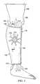
- FIG. 1is an elevation view of an illustrative embodiment of a dressing for treating a venous leg ulcer or other wound on a patient;
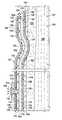
- FIG. 2is a cross section (medial) of the dressing of FIG. 1 taken along line 2 - 2 ;
- FIG. 3is a cross section of a portion of an illustrative embodiment of a wound dressing for treating a wound, such as a venous leg ulcer, that shows another seal against a patient's epidermis;
- FIG. 4is a perspective view of an illustrative embodiment of a dressing for treating a wound, such as venous leg ulcer or other wound;
- FIG. 5is a cross section of a portion of another illustrative embodiment of a dressing for treating a wound, such as venous leg ulcer;
- FIG. 6is a cross section of a portion of another illustrative embodiment of a dressing for treating a wound, such as venous leg ulcer;
- FIG. 7is a cross section of a portion of another illustrative embodiment of a dressing for treating a wound, such as venous leg ulcer;
- FIG. 8is a cross section of a portion of another illustrative embodiment of a dressing for treating a wound, such as venous leg ulcer;
- FIG. 9is a cross section of another illustrative embodiment of a dressing for treating a wound, such as venous leg ulcer;
- FIG. 10is an elevation view of an illustrative embodiment of a dressing for treating a wound, such as venous leg ulcer, on a patient;
- FIG. 11is a schematic diagram of a control subsystem for use with a dressing for treating a wound, such as venous leg ulcer.
- FIG. 12is an elevation view of another dressing for treating a wound, such as venous leg ulcer, on a patient.
- VLUvenous leg ulcer
- VLU'sproduce considerable liquids that can saturate a dressing, cause an undesirable odor, and cause maceration of healthy skin.
- the dressings and systems hereincontrol the liquid from the wound in a way to avoid one or more of these conditions.
- a dressing 102 for treating a wound 104such as a venous leg ulcer, on a limb 106 or extremity of a patient 108 is presented.
- the wound 104may involve epidermis 103 , dermis 105 , and subcutaneous tissue 107 .
- the dressing 102reduces the amount of liquid from the wound 104 that is retained within the dressing 102 by using air movement to vaporize and remove fluids.
- the dressing 102may reduce odor and may facilitate an overall smaller size dressing than might otherwise be possible.
- the dressing 102may have a longer use time than otherwise possible.
- the dressing 102includes a tubular sleeve member 110 for receiving the limb 106 or extremity of the patient 108 .
- the tubular sleeve member 110has limb openings 112 : a first limb opening 114 and a second limb opening 116 .
- the limb openings 112allow the tubular sleeve member 110 to receive the limb 106 therein.
- the tubular sleeve member 110 and the limb openings 112may be sized to accommodate different sized limbs 106 .
- the tubular sleeve member 110may include an elastic compression member 118 formed as a sleeve.
- the elastic compression member 118is the outermost (furthest from patient 108 ) member of the tubular sleeve member 110 .
- the elastic compression member 118has a first side 120 and a second, patient-facing side 122 .
- the elastic compression member 118may be formed from one or more of the following materials: Nylon Powernet material; Velband; materials with combinations of relatively non-elastic nylon fibers and highly-elastic fibers (e.g., Spandex, Elastene); Lycra materials, stretch cotton; rubber materials; urethanes; silicones; or other stretch based materials.
- the elastic compression member 118is optional in that an embodiment may be used as a dressing without this layer. In such a case, the next layer, a fluid-directing member 124 , may securely hold the dressing 102 in place.
- the tubular sleeve member 110also includes the fluid-directing member 124 ,
- the fluid-directing member 124has a first side 126 and a second, patient-facing side 128 .
- the first side 126 of the fluid-directing member 124is disposed proximate to the second, patient-facing side 122 of the elastic compression member 118 .
- the fluid-directing member 124is operable to inhibit fluids from flowing through the fluid-directing member 124 .
- the fluid-directing membermay comprise one or more of the following a polyurethane (PU) drape; an elastomer (e.g., natural rubbers, polyisoprene, styrene butadiene rubber, chloroprene rubber, polybutadiene, nitrile rubber, butyl rubber, ethylene propylene rubber, ethylene propylene diene monomer, chlorosulfonated polyethylene, polysulfide rubber, EVA film, co-polyester, and silicones; silicone drape material; a 3M Tegaderm® drape; or a polyurethane (PU) drape.
- the fluid-directing member 124directs fluids so that airflow is primarily out of the exhaust ports.
- the fluid-directing member 124may extend beyond any other layers to form an extension 130 .
- the extension 130forms a seal with the patient's epidermis 103 as shown best in FIG. 2 .
- the extension 130has a first side 134 and a second, patient-facing side 136 .
- An adhesive 138is applied to the second, patient-facing side 136 of the extension 130 to facilitate attachment to the patient's epidermis 103 .
- a port 140which depending on mode of operation is an intake port or an exhaust port, is formed through the fluid directing member 124 and any other members as necessary to access air beyond the wound dressing 102 .
- the port 140allows fluid to enter or exit the wound dressing 102 .
- the elastic compression member 118 and fluid-directing member 124both extend over transverse edges 142 and, because of compression, impinge upon the epidermis 103 to form a seal.
- the port 140extends through both the elastic compression member 118 and fluid-directing member 124 .
- all the layersmay be coterminous and the entire edge may serve to exhaust vapor.
- the tubular sleeve member 110further includes a pathway member 144 .
- the pathway member 144has a first side 146 and a second, patient-facing side 148 .
- the first side 146 of the pathway member 144is proximate to the second, patient-facing side 128 of the fluid-directing member 124 .
- the pathway member 144is operable to transport a fluid under a pressure gradient.
- the pathway member 144functions to present pathways that allow a gas to flow and has sufficient rigidity to allow pathways to remain open even when compressed during use.
- the pathway member 144may comprise one or more of the following: open-cell foam; non-woven material (e.g., Libeltex Hydrophobic non-woven); or Vilmed range from Freundenberg 1522.
- open-cell foame.g., Libeltex Hydrophobic non-woven
- non-woven materiale.g., Libeltex Hydrophobic non-woven
- Vilmed range from Freundenberg 1522As suggested by arrows 150 in FIG. 2 , air moves within the pathway member 144 . Arrows 150 show airflow in one direction, but another direction is possible as is explained elsewhere.
- the tubular sleeve member 110may optionally include an absorbent member 152 .
- the absorbent member 152at least temporarily retains liquids from the wound 104 away from the patient's epidermis 103 .
- the absorbent member 152has a first side 154 and a second, patient-facing side 156 .
- the first side 154 of the absorbent member 152is proximate to the second, patient-facing side 148 of the pathway member 144 .
- the absorbent member 152acts as a buffer to hold liquid from the wound 104 while waiting for the liquid to be evaporated and carried away by airflow in the pathway member 144 .
- the absorbent member 152may be any material that functions to hold liquid.
- the absorbent member 152may be formed from one or more of the following: a super absorbent polymer material (e.g., LUQUAFLEECE from BASF), Vilmed range from Freundenberg 1522, or other material.
- the tubular sleeve member 110may optionally include a transition member 158 .
- the transition member 158may be formed from the same materials as the pathway member 144 .
- the transition member 158has a first side 160 and a second, patient-facing side 162 .
- the first side 160 of the transition member 158is disposed proximate to the second, patient-facing side 156 of the absorbent member 152 .
- the transition member 158wicks liquids from the wound 104 to help keep fluids away from the epidermis 103 or wound 104 .
- the tubular sleeve member 110may optionally include a patient-interface member 164 that has a first side 166 and a second, patient-facing side 168 .
- the first side 166 of the patient-interface member 164is disposed proximate to the second, patient-facing side 162 of the transition member 158 or the second, patient-facing side 156 of the absorbent member 152 .
- the second, patient-facing side 168 of the patient-interface member 164is for disposing proximate to the patient 108 .
- the patient-interface member 164is designed to be against the epidermis 103 for extended periods of time and may include an anti-microbial material, e.g., silver.
- the patient-interface member 164may be formed from a Silver Miliken or other material.
- a pressure source 170is fluidly coupled to the tubular sleeve member 110 .
- the pressure source 170may be, for example, a reduced-pressure source or a positive pressure source.
- the pressure source 170may be a micro-pump 172 as shown in FIG. 2 , a remote reduced-pressure source 174 as shown in FIG. 10 , a wall-based suction source, or a wall-based positive pressure source.
- the pressure source 170may be configured to pull air into the wound dressing 102 at an inboard location.
- the wound dressing 102may be configured to discharge the air at the edges.
- the airis discharged through one port 140 at the limb opening 112 as suggested by arrows 178 .
- the pressure source 170may be configured to pull air as suggested by arrows 180 in FIG. 10 from the limb openings 112 to the pressure source 170 and then exhaust the air at the reduced-pressure source 174 .
- the wound dressing 102includes at least two ports: port 140 and port 182 .
- the limb openings 112typically include at least one port 140 .
- a plurality of ports 140may be included.
- the port or ports 140may function as exhaust ports or intake ports depending on the configuration of the pressure source 170 .
- the port 140is an exhaust port.
- the ports 140are intake ports.
- the port 182is associated with the pressure source 170 and may include an extension portion 185 to provide fluid communication with a desired layer of the wound dressing 102 .
- the extension portion 185may fluidly couple the pressure source 170 to the pathway member 144 as shown in FIG. 2 or to another layer if desired.
- the pressure source 170causes a pressure gradient in the wound dressing 102 that will move air. Depending on how the wound dressing 102 is configured, air either enters at the edges (e.g., at the limb opening 112 ) and moves to port 182 or enters at the port 182 and moves to the limb opening 112 and out ports 140 .
- the ports 140 and 182may both may be inboard if a compartment wall is used as is described elsewhere herein.
- the pressure gradientis typically established primarily in the pathway member 144 , but may be established in other layers in some embodiments.
- Each port 140 , 182may have a filter associated with the port 140 , 182 .
- a filter 184is associated with port 140
- a filter 186is associated with port 182 .
- the filters 184 , 186may be odor filters, e.g., charcoal filters, or anti-bacterial filters.
- the filter 184is a charcoal filter for removing odor from the airflow before the airflow is released into the atmosphere.
- the filter 186is an intake filter for removing bacteria before the air enters the wound dressings 102 .
- the intake filters (not explicitly shown) associated with ports 140are anti-bacterial intake filters.
- the tubular sleeve member 110 of the wound dressing 102comprises only an elastic compression member 118 , a fluid-directing member 124 , and pathway member 144 .
- FIG. 5the tubular sleeve member 110 of the wound dressing 102 comprises only an elastic compression member 118 , a fluid-directing member 124 , and pathway member 144 .
- the tubular sleeve member 110 of the wound dressing 102comprises an elastic compression member 118 , a fluid-directing member 124 , pathway member 144 , and an absorbent member 152 .
- the tubular sleeve member 110 of the wound dressing 102comprises an elastic compression member 118 , a fluid-directing member 124 , pathway member 144 , an absorbent member 152 , and a transition member 158 .
- the tubular sleeve member 110 of the wound dressing 102comprises an elastic compression member 118 , a fluid-directing member 124 , and a woven-open-structure member 188 .
- the woven-open-structure member 188functionally combines the pathway member 144 , absorbent member 152 , and the transition member 158 into one material.
- the woven-open-structure member 188is operable to retain fluids and at the same time allow gases to move in the woven-open-structure member 188 .
- the woven-open-structure member 188may be formed from Vilmed range from Freundenberg 1522 or other similar material, for example.
- FIG. 9another illustrative embodiment of a wound dressing 102 for treating a wound 104 on a limb 106 of a patient 108 is presented.
- the cross sectionis a medial cross section of the limb 106 with the wound dressing 102 applied thereto.
- the wound dressing 102is analogous in most respects to the wound dressing of FIGS. 1-2 , except the elastic compression member 118 is omitted and additional features added as will be explained.
- the wound dressing 102may be formed as an annular sleeve, as an isolated dressing, or island dressing.
- the wound dressing 102may be used with or without compression. If compression is desired, the compression is developed by application of the fluid-directing member 124 in tension.
- the wound dressing 102is held by adhesive 138 to the patient 108 .
- a control subsystem 202is included.
- the control subsystem 202includes at least one saturation sensor 190 .
- the saturation sensor 190is coupled to the absorbent member 152 .
- the saturation sensor 190may be coupled to other layers, e.g., the transition member 158 .
- the saturation sensor 190may be a galvanic cell with two electrodes that produce voltage when saturated, a resistive pathway that is completed by exudate, or a capacitor-based sensor.
- the saturation sensor 190is coupled to a control circuit or controller 192 .
- the controller 192is configured to monitor the saturation sensor 190 .
- the controller 192detects a change indicative that the absorbent member 152 is saturated or partially saturated, the controller 192 activates the pressure source 170 in response.
- the pressure sourcein this embodiment pulls gas from the port 182 and discharges the gas to the atmosphere as suggested by arrows 194 .
- the airis pulled from the transverse edges 142 through one or more ports 140 .
- the ports 140may have a control valve 196 associated with each port 140 .
- the control valve 196may be wirelessly or electrically coupled by a lead 199 to the controller 192 .
- the control valve 196regulates air flow through the one or more ports 140 to keep air moving in the wound dressing 102 , but also to control the rate such that, if desired, a reduced pressure may be maintained in a sealed space 198 at a desired level.
- controlled leaks in the fluid-directing member 124may be used.
- the controlled leaksallow air to flow in at or near the transverse edges 142 towards the pressure source 170 .
- apertures (not explicitly shown) in the fluid-directing member 124may be covered by an adhesive film that is removed later when a leak is desired.
- a reduced pressuremay be applied to the wound 104 and liquids removed and managed.
- the reduced pressureis initially applied by the pressure source 170 .
- the control valve 196may be at least partially opened to allow some fluid flow into the wound dressing 102 and at the same time the pressure source 170 may be sufficiently increased to hold the desired reduced pressure notwithstanding the introduction of air through ports 140 .
- a display 200may be added to the control subsystem 202 to provide feedback to a user.
- the display 200may be a series of LED indicators, a bi-stable LCD type, or other compact display.
- the display 200is compact and low power.
- the display 200may display information such as remaining battery capacity, duration of therapy, and the fill status of the dressing as well as confirmation that the system is operating within its normal parameters.
- FIG. 10another illustrative embodiment of a wound dressing 102 for treating a wound 104 on a limb 106 of a patient 108 is presented.
- the wound dressing 102is analogous to those previously presented, except in this embodiment, the pressure source 170 is a remote reduced-pressure source 174 .
- the remote reduced-pressure source 174is fluidly coupled by a pressure conduit 204 to the tubular sleeve member 110 .
- a pressure interface 206may be used to fluidly couple the pressure conduit 204 to the intake port (see port 182 in FIG. 2 ).
- the intake portis at an inboard location on the wound dressing 102 .
- the pressure interface 206is a T.R.A.C.® Pad or Sensa T.R.A.C.® Pad available from KCI of San Antonio, Tex., or another interface.
- a “bridge”an open-cell foam or other passageway material enclosed in a gas-impermeable material is used to deliver reduced pressure to the wound dressing 102 .
- the control subsystem 202includes a controller 192 that is coupled to a saturation sensor 190 and to a pressure source 170 .
- a control valve 196may be coupled to the controller 192 and also a display 200 .
- the control subsystem 202may control the leak rate by opening the control valve 196 when included or may turn on, turn off, increase, or decrease the pressure produced by the pressure source 170 .
- “or”does not require mutual exclusivity.
- the control valve 196may be a solenoid valve such as Pneutronics X valve with a fixed size orifice from Parker Hannifin, Cleveland, Ohio; a mechanical proportional valve; or a PZT proportional valve such as those supplied by Festo.
- control subsystem 202 of FIG. 11 or aspects of the control subsystem 202may be applied to any of the embodiments herein.
- the saturation sensor 190 and controller 192determine when the absorbent member 152 is saturated or partially saturated.
- the controller 192may then activate the pressure source 170 to initiate airflow in the wound dressing 102 to evaporate and remove liquids from the wound dressing 102 .
- the sensor 109 and controller 192may detect saturation as a scale.
- the duration of the airflow or the speed of the airflowmay be set by the controller 192 in response to the degree of saturation involved.
- the control system 202may also display information such as remaining battery capacity, duration of therapy, and the fill status of the dressing as well as confirmation that the system is operating within its normal parameters.
- FIG. 12another illustrative embodiment of a wound dressing 102 is presented.
- the wound dressing 102is analogous in most respects to the previously presented wound dressings, except in this embodiment, a plurality of pressure compartments 208 are added and are used to massage the limb 106 .
- Each pressure compartment 208is operable to form a pressure gradient on a portion of the patient's limb 106 to move air for the purposes previously presented.
- the pressure compartments 208which are formed with a plurality of compartment walls 209 , allow squeezing or sequenced movement in a cephaladic direction.
- a pressure source 170is fluidly coupled separately to each of the pressure compartments 208 by a plurality of pressure conduits 205 .
- Each pressure compartment 208has a pressure interface 206 for fluidly coupling the pressure conduit 205 to the pressure compartment 208 .
- Each pressure conduit 205is also fluidly coupled to the pressure source 170 .
- a controller 192is coupled to the pressure source 170 to control pressure delivery to the plurality of pressure compartments 208 .
- the controller 192 and pressure source 170are operable to cause a first pressure compartment 210 of the plurality of pressure compartments 208 to compress around the patient's limb 106 , then subsequently a second pressure compartment 212 of the plurality of pressure compartments 208 to compress around the patient's limb 106 in order to encourage fluid movement in the patient's limb 106 from proximate the first pressure compartment 210 towards the second pressure compartment 212 .
- the coordinated compression of pressure compartments 208may continue with the others.
- the pressure source 170may have a controller 192 associated with the pressure source 170 .
- the controller 192may be configured to control a plurality of pumps within the pressure source 170 or a plurality of valves (not explicitly shown) to allow varying pressure within the pressure compartments 208 .
- the controller 192can sequentially supply a pressure gradient to the pressure compartments 208 to cause sequential compression of the compartments on the patient's limb 106 .
- the sequential compression of each pressure compartmentresults in moving fluids in the patient's limb in a cephaladic direction (in the direction that goes from the feet towards the head). This motion thus creates a massage like motion on the limb 106 .
- air flowmay be introduced into the wound dressing 102 to facilitate evaporation and removal of liquids.
- each pressure compartment 208may be achieved using positive pressure or reduced pressure from the pressure source 170 . If positive pressure is used, the pressure compartments 208 may include bladders that fill to cause compression. If reduced pressure is used, the reduced pressure may cause the fluid-directing member 124 to pull down on the other layers which act as a bolster and thereby generate a compressive force.
- a wound dressing 102is provided.
- the wound dressing 102may be any of those presented or suggested herein or combinations thereof.
- the wound dressing 102includes a tubular sleeve member 110 .
- the wound dressing 102is disposed around the patient's limb 106 proximate to the wound 104 . This may entail sliding the patient's limb 106 through the limb openings 112 or using an open and closeable seam (not explicitly shown).
- the wound dressing 102may receive liquid from the wound 104 into the wound dressing 102 . Either all the time, in response to saturation or partial saturation, or based on a timer, the pressure source 170 is activated. The pressure source 170 creates a pressure gradient within the wound dressing 102 that causes air flow in the wound dressing 102 to evaporate liquid from the wound dressing 102 . The air enters the wound dressing 102 at one location (e.g., port 182 or port 140 ) and is exhausted at another location (e.g., port 140 or 182 ).
- one locatione.g., port 182 or port 140
- the airtypically will travel within the wound dressing 102 at a rate of at least 0.1 m/s and is typically in the range 0.01 (or less) to 0.2 m/s. If a saturation sensor 190 and controller 192 are included, they may detect when the saturation has dropped below a threshold level and then signal the pressure source 170 to cease. With spaced intake and exhaust ports, the air will flow over a large portion of the interior of the wound dressing 102 . For example, the air may flow over 50 percent, 75 percent, 90% percent or more of the surface area of the pathway member 144 (or other layer if coupled to another layer).
- reduced pressuremay also be applied to the wound 104 as an aspect of treatment.
- the control valve 196may remain closed or restricted while reduced pressure is applied to the sealed space 198 to allow the creation of reduced pressure in the sealed space 198 .
- the pressuremay be, for example, without limitation, in the ⁇ 25 mm Hg to ⁇ 200 mm Hg range. If saturation is detected, the control valve 196 may be opened to allow for increased air flow.
- the output of the pressure source 170may be increased to allow the reduced pressure level to be maintained in the sealed space 198 notwithstanding the leak or bleeding of air.
- the air entering or exiting the wound dressing 102 through ports 140 and 182may first go through a filter 184 , 186 .
- the filters 184 , 186remove bacteria or odor.
- the intake filterwill keep bacteria from entering the wound dressing 102 and potentially infecting the wound 104 .
- the exit filterhelps remove particulates or remove odors.
- the configuration of the pressure source 170determines whether a filter is an intake filter or exit filter.
- a method of manufacturing a wound dressing 102 for treating a wound 104 on a patient's limb 106includes forming a tubular sleeve member 110 for receiving the patient's lower extremity or limb 106 .
- the step of forming the tubular sleeve member 110includes forming an elastic compression member 118 as a sleeve having a first side 120 and a second, patient-facing side 122 ; forming a fluid-directing member 124 having a first side 126 and a second, patient-facing side 128 ; and disposing the first side 126 of the fluid-directing member 124 proximate to the second, patient-facing side 122 of the elastic compression member 118 .
- the fluid-directing member 124is operable to inhibit fluids from flowing through the fluid-directing member 124 .
- the step of forming the tubular sleeve member 110further includes forming a pathway member 144 having a first side 146 and a second, patient-facing side 148 and disposing the first side 146 of the pathway member 144 proximate to the second, patient-facing side 128 of the fluid-directing member 124 .
- the pathway member 144is operable to transport a fluid under a pressure gradient.
- the methodfurther includes fluidly coupling the pressure source 170 to, the pathway member 144 for moving fluid therein.
- the step of forming a tubular sleeve member 110may further include disposing an absorbent member 152 , which is for at least temporarily retaining liquids, into the wound dressing 102 .
- the absorbent member 152has a first side 154 and a second, patient-facing side 156 .
- the first side 154 of the absorbent member 152is disposed proximate to the second, patient-facing side 148 of the pathway member 144 .
- the step of forming a tubular sleeve member 110may further include disposing a transition member 158 proximate to the absorbent member 152 or disposing the patient-interface member 164 into the wound dressing 102 .
- One or more layersmay be omitted and the order of the layers may be varied.
- the wound dressing 102may be configured to accommodate air flow in others layers except the fluid-directing member 124 .
- the extension portion 185 ( FIG. 2 ) of the port 182may extend to the absorbent member 152 or the transition member 158 to cause airflow primarily therein.
- airflowmay be from an inboard location to the transverse edges 142 , from the transverse edges 142 to an inboard location, or from an inboard location to another inboard location.
- an embodiment of a wound dressing 102has the intake port and exhaust port that are both inboard of the transverse edges 142 , but separated by a medial compartment wall (not shown, but analogous to compartment wall 209 in FIG. 12 and running medially).
- the transverse edges 142are sealed, air enters the intake port proximate to the compartment wall, the air transversely flows around the limb 106 , and then the air exits the exhaust port proximate to the compartment wall but on the opposite side from the intake port.
- the wound dressings 102 hereinmay require fewer changes than other wound dressings because of the liquid management, i.e., the liquid removed by the airflow.
- the liquid managementmay also avoid maceration on the patient.
- the wound dressings 102may provide less odor and bulk than other dressings.
- the wound dressing 102may process more liquid over time that the dressing is otherwise capable of retaining.
Landscapes
- Health & Medical Sciences (AREA)
- Heart & Thoracic Surgery (AREA)
- Engineering & Computer Science (AREA)
- Public Health (AREA)
- Vascular Medicine (AREA)
- Biomedical Technology (AREA)
- Veterinary Medicine (AREA)
- Life Sciences & Earth Sciences (AREA)
- Animal Behavior & Ethology (AREA)
- General Health & Medical Sciences (AREA)
- Anesthesiology (AREA)
- Hematology (AREA)
- Manufacturing & Machinery (AREA)
- Epidemiology (AREA)
- Chemical & Material Sciences (AREA)
- Medicinal Chemistry (AREA)
- Media Introduction/Drainage Providing Device (AREA)
- External Artificial Organs (AREA)
Abstract
Description
Claims (15)
Priority Applications (3)
| Application Number | Priority Date | Filing Date | Title |
|---|---|---|---|
| US13/674,782US9433711B2 (en) | 2011-11-11 | 2012-11-12 | Dressings, systems, and methods for treating a wound on a patient's limb employing liquid control |
| US15/229,422US10179196B2 (en) | 2011-11-11 | 2016-08-05 | Dressings, systems, and methods for treating a wound on a patient's limb employing liquid control |
| US16/212,366US20190167861A1 (en) | 2011-11-11 | 2018-12-06 | Dressings, Systems, And Methods For Treating A Wound On A Patient's Limb Employing Liquid Control |
Applications Claiming Priority (2)
| Application Number | Priority Date | Filing Date | Title |
|---|---|---|---|
| US201161558544P | 2011-11-11 | 2011-11-11 | |
| US13/674,782US9433711B2 (en) | 2011-11-11 | 2012-11-12 | Dressings, systems, and methods for treating a wound on a patient's limb employing liquid control |
Related Child Applications (1)
| Application Number | Title | Priority Date | Filing Date |
|---|---|---|---|
| US15/229,422ContinuationUS10179196B2 (en) | 2011-11-11 | 2016-08-05 | Dressings, systems, and methods for treating a wound on a patient's limb employing liquid control |
Publications (2)
| Publication Number | Publication Date |
|---|---|
| US20130123722A1 US20130123722A1 (en) | 2013-05-16 |
| US9433711B2true US9433711B2 (en) | 2016-09-06 |
Family
ID=47215802
Family Applications (3)
| Application Number | Title | Priority Date | Filing Date |
|---|---|---|---|
| US13/674,782Active2034-08-31US9433711B2 (en) | 2011-11-11 | 2012-11-12 | Dressings, systems, and methods for treating a wound on a patient's limb employing liquid control |
| US15/229,422Active2033-08-05US10179196B2 (en) | 2011-11-11 | 2016-08-05 | Dressings, systems, and methods for treating a wound on a patient's limb employing liquid control |
| US16/212,366AbandonedUS20190167861A1 (en) | 2011-11-11 | 2018-12-06 | Dressings, Systems, And Methods For Treating A Wound On A Patient's Limb Employing Liquid Control |
Family Applications After (2)
| Application Number | Title | Priority Date | Filing Date |
|---|---|---|---|
| US15/229,422Active2033-08-05US10179196B2 (en) | 2011-11-11 | 2016-08-05 | Dressings, systems, and methods for treating a wound on a patient's limb employing liquid control |
| US16/212,366AbandonedUS20190167861A1 (en) | 2011-11-11 | 2018-12-06 | Dressings, Systems, And Methods For Treating A Wound On A Patient's Limb Employing Liquid Control |
Country Status (7)
| Country | Link |
|---|---|
| US (3) | US9433711B2 (en) |
| EP (1) | EP2775974B1 (en) |
| JP (1) | JP6158202B2 (en) |
| CN (1) | CN103889377B (en) |
| AU (3) | AU2012335000B2 (en) |
| CA (1) | CA2850958C (en) |
| WO (1) | WO2013071253A1 (en) |
Cited By (7)
| Publication number | Priority date | Publication date | Assignee | Title |
|---|---|---|---|---|
| US10076462B2 (en) | 2016-04-27 | 2018-09-18 | Radial Medical, Inc. | Adaptive compression therapy systems and methods |
| US10960129B2 (en)* | 2017-08-25 | 2021-03-30 | AZ Solutions LLC | System and method for patient skin treatment and irrigation |
| WO2021209949A1 (en) | 2020-04-16 | 2021-10-21 | Kci Licensing, Inc. | Systems and methods for active evaporation of a wound therapy system |
| WO2022195377A1 (en) | 2021-03-17 | 2022-09-22 | Kci Manufacturing Unlimited Company | Evaporative fluid management canister for wound therapy system |
| US11918549B2 (en) | 2017-08-25 | 2024-03-05 | AZ Solutions LLC | System and method for wound treatment and irrigation |
| US12403214B2 (en)* | 2018-05-21 | 2025-09-02 | Milliken & Company | Wound care device having fluid transfer and adhesive properties |
| US12440460B2 (en) | 2023-10-26 | 2025-10-14 | AZ Solutions LLC | System and method for wound treatment and irrigation |
Families Citing this family (50)
| Publication number | Priority date | Publication date | Assignee | Title |
|---|---|---|---|---|
| USD733896S1 (en) | 2012-05-04 | 2015-07-07 | Genadyne Biotechnologies, Inc. | Abdominal dressing |
| ES2817834T3 (en) | 2013-03-12 | 2021-04-08 | 3M Innovative Properties Co | System that uses vacuum to promote the healing of sprains |
| US10226566B2 (en) | 2014-04-23 | 2019-03-12 | Genadyne Biotechnologies, Inc. | System and process for removing bodily fluids from a body opening |
| US12274823B2 (en) | 2015-11-20 | 2025-04-15 | Solventum Intellectual Properties Company | Medical system and dressing for use under compression |
| WO2017087163A1 (en) | 2015-11-20 | 2017-05-26 | Kci Licensing, Inc. | Medical system with flexible fluid storage bridge |
| WO2017132144A1 (en)* | 2016-01-28 | 2017-08-03 | Kci Licensing, Inc. | Sequential collapse waveform dressing |
| US20190076298A1 (en)* | 2016-03-14 | 2019-03-14 | Smith & Nephew Plc | Wound dressing apparatus with flexible display |
| CA3023772A1 (en) | 2016-05-13 | 2017-11-16 | Smith & Nephew Plc | Sensor enabled wound monitoring and therapy apparatus |
| SE1651629A1 (en)* | 2016-12-12 | 2018-06-13 | Jasa Medical As | Compression garment |
| JP7091356B2 (en) | 2017-03-09 | 2022-06-27 | スミス アンド ネフュー ピーエルシー | Devices, devices, and methods for determining skin perfusion pressure |
| EP3592230A1 (en) | 2017-03-09 | 2020-01-15 | Smith & Nephew PLC | Apparatus and method for imaging blood in a target region of tissue |
| US11690570B2 (en) | 2017-03-09 | 2023-07-04 | Smith & Nephew Plc | Wound dressing, patch member and method of sensing one or more wound parameters |
| AU2018234981B2 (en)* | 2017-03-15 | 2023-09-28 | Smith & Nephew Plc | Multiple dressing negative pressure wound therapy system with calibrated leak paths |
| CA3059516A1 (en) | 2017-04-11 | 2018-10-18 | Smith & Nephew Plc | Component positioning and stress relief for sensor enabled wound dressings |
| EP3635733A1 (en) | 2017-05-15 | 2020-04-15 | Smith & Nephew plc | Negative pressure wound therapy system using eulerian video magnification |
| AU2018269112B2 (en) | 2017-05-15 | 2024-05-02 | Smith & Nephew Plc | Wound analysis device and method |
| JP7189159B2 (en) | 2017-06-23 | 2022-12-13 | スミス アンド ネフュー ピーエルシー | Sensor placement for sensor-enabled wound monitoring or therapy |
| GB201804502D0 (en) | 2018-03-21 | 2018-05-02 | Smith & Nephew | Biocompatible encapsulation and component stress relief for sensor enabled negative pressure wound therapy dressings |
| GB201809007D0 (en) | 2018-06-01 | 2018-07-18 | Smith & Nephew | Restriction of sensor-monitored region for sensor-enabled wound dressings |
| SG11202000913XA (en) | 2017-08-10 | 2020-02-27 | Smith & Nephew | Positioning of sensors for sensor enabled wound monitoring or therapy |
| GB201804971D0 (en) | 2018-03-28 | 2018-05-09 | Smith & Nephew | Electrostatic discharge protection for sensors in wound therapy |
| GB201718870D0 (en) | 2017-11-15 | 2017-12-27 | Smith & Nephew Inc | Sensor enabled wound therapy dressings and systems |
| CN111093477B (en) | 2017-09-10 | 2023-09-12 | 史密夫及内修公开有限公司 | Systems and methods for inspecting packages and components in sensor-equipped wound dressings |
| GB201718859D0 (en) | 2017-11-15 | 2017-12-27 | Smith & Nephew | Sensor positioning for sensor enabled wound therapy dressings and systems |
| WO2019063481A1 (en) | 2017-09-27 | 2019-04-04 | Smith & Nephew Plc | Ph sensing for sensor enabled negative pressure wound monitoring and therapy apparatuses |
| WO2019072531A1 (en) | 2017-09-28 | 2019-04-18 | Smith & Nephew Plc | Neurostimulation and monitoring using sensor enabled wound monitoring and therapy apparatus |
| CN107753181A (en)* | 2017-10-19 | 2018-03-06 | 中国计量大学 | The topical application of drug device of disease of skin |
| US12127916B2 (en) | 2017-10-23 | 2024-10-29 | Solventum Intellectual Properties Company | High-density evaporative bridge dressing |
| IT201700120992A1 (en)* | 2017-10-25 | 2019-04-25 | S2Medical Ab | APPARATUS FOR NEGATIVE PRESSURE THERAPY FOR WOUNDS. |
| US11559438B2 (en) | 2017-11-15 | 2023-01-24 | Smith & Nephew Plc | Integrated sensor enabled wound monitoring and/or therapy dressings and systems |
| CN110227024B (en)* | 2018-03-05 | 2021-10-01 | 依奈德医疗技术(上海)有限公司 | Compression system for treating varicose veins of lower limbs |
| GB201803848D0 (en)* | 2018-03-09 | 2018-04-25 | Crawford Woundcare Ltd | Wound dressing |
| WO2019199389A1 (en)* | 2018-04-10 | 2019-10-17 | Kci Licensing, Inc. | Bridge dressing with fluid management |
| WO2019200035A1 (en)* | 2018-04-13 | 2019-10-17 | Kci Licensing, Inc. | Npwt system with selectively controllable airflow |
| US11534343B2 (en) | 2018-07-31 | 2022-12-27 | Kci Licensing, Inc. | Devices and methods for preventing localized pressure points in distribution components for tissue therapy |
| EP3829515A1 (en) | 2018-08-01 | 2021-06-09 | KCI Licensing, Inc. | Soft-tissue treatment with negative pressure |
| GB201814011D0 (en) | 2018-08-29 | 2018-10-10 | Smith & Nephew | Componet positioning and encapsulation for sensor enabled wound dressings |
| EP3849401A1 (en) | 2018-09-12 | 2021-07-21 | Smith & Nephew plc | Device, apparatus and method of determining skin perfusion pressure |
| WO2020064937A1 (en) | 2018-09-28 | 2020-04-02 | T.J.Smith And Nephew,Limited | Optical fibers for optically sensing through wound dressings |
| GB201816838D0 (en) | 2018-10-16 | 2018-11-28 | Smith & Nephew | Systems and method for applying biocompatible encapsulation to sensor enabled wound monitoring and therapy dressings |
| GB201820927D0 (en) | 2018-12-21 | 2019-02-06 | Smith & Nephew | Wound therapy systems and methods with supercapacitors |
| JP7529681B2 (en) | 2019-03-18 | 2024-08-06 | スミス アンド ネフュー ピーエルシー | Design rules for sensor integrated boards |
| WO2020205445A1 (en) | 2019-03-29 | 2020-10-08 | Kci Licensing, Inc. | Negative-pressure treatment with area stabilization |
| EP3946502A1 (en) | 2019-03-29 | 2022-02-09 | KCI Licensing, Inc. | Dressing with integrated pump and releasably coupled pump actuator |
| WO2020205449A1 (en) | 2019-03-29 | 2020-10-08 | Kci Licensing, Inc. | Negative-pressure treatment with area stabilization |
| US11504466B2 (en) | 2019-04-08 | 2022-11-22 | Jeffrey Hegg | Medical gauze and gas flow assembly and method of applying a medical gauze with gas flow on a wound |
| GB201914443D0 (en) | 2019-10-07 | 2019-11-20 | Smith & Nephew | Sensor enabled negative pressure wound monitoring apparatus with different impedances inks |
| EP4139904A1 (en) | 2020-04-21 | 2023-03-01 | T.J. Smith and Nephew, Limited | Wound treatment management using augmented reality overlay |
| US20240238502A1 (en)* | 2021-05-13 | 2024-07-18 | Kci Manufacturing Unlimited Company | Low profile dual fluid instillation and removal bridge system with fluid delivery and pressure sensing capabilities |
| KR102658992B1 (en)* | 2023-08-24 | 2024-04-19 | 주식회사 에너지마이닝 | Self-Care Capable Smart Band for Wound and Smart Band control system including the same |
Citations (141)
| Publication number | Priority date | Publication date | Assignee | Title |
|---|---|---|---|---|
| US1355846A (en) | 1920-02-06 | 1920-10-19 | David A Rannells | Medical appliance |
| US2547758A (en) | 1949-01-05 | 1951-04-03 | Wilmer B Keeling | Instrument for treating the male urethra |
| US2632443A (en) | 1949-04-18 | 1953-03-24 | Eleanor P Lesher | Surgical dressing |
| GB692578A (en) | 1949-09-13 | 1953-06-10 | Minnesota Mining & Mfg | Improvements in or relating to drape sheets for surgical use |
| US2682873A (en) | 1952-07-30 | 1954-07-06 | Johnson & Johnson | General purpose protective dressing |
| US2910763A (en) | 1955-08-17 | 1959-11-03 | Du Pont | Felt-like products |
| US2969057A (en) | 1957-11-04 | 1961-01-24 | Brady Co W H | Nematodic swab |
| US3066672A (en) | 1960-09-27 | 1962-12-04 | Jr William H Crosby | Method and apparatus for serial sampling of intestinal juice |
| US3367332A (en) | 1965-08-27 | 1968-02-06 | Gen Electric | Product and process for establishing a sterile area of skin |
| US3520300A (en) | 1967-03-15 | 1970-07-14 | Amp Inc | Surgical sponge and suction device |
| US3568675A (en) | 1968-08-30 | 1971-03-09 | Clyde B Harvey | Fistula and penetrating wound dressing |
| US3648692A (en) | 1970-12-07 | 1972-03-14 | Parke Davis & Co | Medical-surgical dressing for burns and the like |
| US3682180A (en) | 1970-06-08 | 1972-08-08 | Coilform Co Inc | Drain clip for surgical drain |
| US3826254A (en) | 1973-02-26 | 1974-07-30 | Verco Ind | Needle or catheter retaining appliance |
| DE2640413A1 (en) | 1976-09-08 | 1978-03-09 | Wolf Gmbh Richard | CATHETER MONITORING DEVICE |
| US4080970A (en) | 1976-11-17 | 1978-03-28 | Miller Thomas J | Post-operative combination dressing and internal drain tube with external shield and tube connector |
| US4096853A (en) | 1975-06-21 | 1978-06-27 | Hoechst Aktiengesellschaft | Device for the introduction of contrast medium into an anus praeter |
| US4139004A (en) | 1977-02-17 | 1979-02-13 | Gonzalez Jr Harry | Bandage apparatus for treating burns |
| US4165748A (en) | 1977-11-07 | 1979-08-28 | Johnson Melissa C | Catheter tube holder |
| US4184510A (en) | 1977-03-15 | 1980-01-22 | Fibra-Sonics, Inc. | Valued device for controlling vacuum in surgery |
| WO1980002182A1 (en) | 1979-04-06 | 1980-10-16 | J Moss | Portable suction device for collecting fluids from a closed wound |
| US4233969A (en) | 1976-11-11 | 1980-11-18 | Lock Peter M | Wound dressing materials |
| US4245630A (en) | 1976-10-08 | 1981-01-20 | T. J. Smith & Nephew, Ltd. | Tearable composite strip of materials |
| US4256109A (en) | 1978-07-10 | 1981-03-17 | Nichols Robert L | Shut off valve for medical suction apparatus |
| US4261363A (en) | 1979-11-09 | 1981-04-14 | C. R. Bard, Inc. | Retention clips for body fluid drains |
| US4275721A (en) | 1978-11-28 | 1981-06-30 | Landstingens Inkopscentral Lic, Ekonomisk Forening | Vein catheter bandage |
| US4284079A (en) | 1979-06-28 | 1981-08-18 | Adair Edwin Lloyd | Method for applying a male incontinence device |
| US4297995A (en) | 1980-06-03 | 1981-11-03 | Key Pharmaceuticals, Inc. | Bandage containing attachment post |
| US4333468A (en) | 1980-08-18 | 1982-06-08 | Geist Robert W | Mesentery tube holder apparatus |
| US4373519A (en) | 1981-06-26 | 1983-02-15 | Minnesota Mining And Manufacturing Company | Composite wound dressing |
| US4381611A (en)* | 1977-10-21 | 1983-05-03 | Phillips Petroleum Company | Method and apparatus for absorbing moisture |
| US4382441A (en) | 1978-12-06 | 1983-05-10 | Svedman Paul | Device for treating tissues, for example skin |
| US4392858A (en) | 1981-07-16 | 1983-07-12 | Sherwood Medical Company | Wound drainage device |
| US4392853A (en) | 1981-03-16 | 1983-07-12 | Rudolph Muto | Sterile assembly for protecting and fastening an indwelling device |
| US4419097A (en) | 1981-07-31 | 1983-12-06 | Rexar Industries, Inc. | Attachment for catheter tube |
| EP0100148A1 (en) | 1982-07-06 | 1984-02-08 | Dow Corning Limited | Medical-surgical dressing and a process for the production thereof |
| US4465485A (en) | 1981-03-06 | 1984-08-14 | Becton, Dickinson And Company | Suction canister with unitary shut-off valve and filter features |
| EP0117632A2 (en) | 1983-01-27 | 1984-09-05 | Johnson & Johnson Products Inc. | Adhesive film dressing |
| US4475909A (en) | 1982-05-06 | 1984-10-09 | Eisenberg Melvin I | Male urinary device and method for applying the device |
| US4480638A (en) | 1980-03-11 | 1984-11-06 | Eduard Schmid | Cushion for holding an element of grafted skin |
| US4525374A (en) | 1984-02-27 | 1985-06-25 | Manresa, Inc. | Treating hydrophobic filters to render them hydrophilic |
| US4525166A (en) | 1981-11-21 | 1985-06-25 | Intermedicat Gmbh | Rolled flexible medical suction drainage device |
| US4540412A (en) | 1983-07-14 | 1985-09-10 | The Kendall Company | Device for moist heat therapy |
| US4543100A (en) | 1983-11-01 | 1985-09-24 | Brodsky Stuart A | Catheter and drain tube retainer |
| US4548202A (en) | 1983-06-20 | 1985-10-22 | Ethicon, Inc. | Mesh tissue fasteners |
| US4551139A (en) | 1982-02-08 | 1985-11-05 | Marion Laboratories, Inc. | Method and apparatus for burn wound treatment |
| EP0161865A2 (en) | 1984-05-03 | 1985-11-21 | Smith and Nephew Associated Companies p.l.c. | Adhesive wound dressing |
| US4556055A (en)* | 1984-10-26 | 1985-12-03 | Bonner F J Jun | Cold compress |
| US4569348A (en) | 1980-02-22 | 1986-02-11 | Velcro Usa Inc. | Catheter tube holder strap |
| US4605399A (en) | 1984-12-04 | 1986-08-12 | Complex, Inc. | Transdermal infusion device |
| US4608041A (en) | 1981-10-14 | 1986-08-26 | Frese Nielsen | Device for treatment of wounds in body tissue of patients by exposure to jets of gas |
| US4640688A (en) | 1985-08-23 | 1987-02-03 | Mentor Corporation | Urine collection catheter |
| US4655754A (en) | 1984-11-09 | 1987-04-07 | Stryker Corporation | Vacuum wound drainage system and lipids baffle therefor |
| US4664662A (en) | 1984-08-02 | 1987-05-12 | Smith And Nephew Associated Companies Plc | Wound dressing |
| WO1987004626A1 (en) | 1986-01-31 | 1987-08-13 | Osmond, Roger, L., W. | Suction system for wound and gastro-intestinal drainage |
| US4710165A (en) | 1985-09-16 | 1987-12-01 | Mcneil Charles B | Wearable, variable rate suction/collection device |
| US4733659A (en) | 1986-01-17 | 1988-03-29 | Seton Company | Foam bandage |
| GB2195255A (en) | 1986-09-30 | 1988-04-07 | Vacutec Uk Limited | Method and apparatus for vacuum treatment of an epidermal surface |
| US4743232A (en) | 1986-10-06 | 1988-05-10 | The Clinipad Corporation | Package assembly for plastic film bandage |
| GB2197789A (en) | 1986-11-28 | 1988-06-02 | Smiths Industries Plc | Anti-foaming disinfectants used in surgical suction apparatus |
| US4758220A (en) | 1985-09-26 | 1988-07-19 | Alcon Laboratories, Inc. | Surgical cassette proximity sensing and latching apparatus |
| US4787888A (en) | 1987-06-01 | 1988-11-29 | University Of Connecticut | Disposable piezoelectric polymer bandage for percutaneous delivery of drugs and method for such percutaneous delivery (a) |
| US4826494A (en) | 1984-11-09 | 1989-05-02 | Stryker Corporation | Vacuum wound drainage system |
| US4838883A (en) | 1986-03-07 | 1989-06-13 | Nissho Corporation | Urine-collecting device |
| US4840187A (en) | 1986-09-11 | 1989-06-20 | Bard Limited | Sheath applicator |
| US4863449A (en) | 1987-07-06 | 1989-09-05 | Hollister Incorporated | Adhesive-lined elastic condom cathether |
| US4872450A (en) | 1984-08-17 | 1989-10-10 | Austad Eric D | Wound dressing and method of forming same |
| US4878901A (en) | 1986-10-10 | 1989-11-07 | Sachse Hans Ernst | Condom catheter, a urethral catheter for the prevention of ascending infections |
| GB2220357A (en) | 1988-05-28 | 1990-01-10 | Smiths Industries Plc | Medico-surgical containers |
| US4897081A (en) | 1984-05-25 | 1990-01-30 | Thermedics Inc. | Percutaneous access device |
| US4906233A (en) | 1986-05-29 | 1990-03-06 | Terumo Kabushiki Kaisha | Method of securing a catheter body to a human skin surface |
| US4906240A (en) | 1988-02-01 | 1990-03-06 | Matrix Medica, Inc. | Adhesive-faced porous absorbent sheet and method of making same |
| US4919654A (en) | 1988-08-03 | 1990-04-24 | Kalt Medical Corporation | IV clamp with membrane |
| CA2005436A1 (en) | 1988-12-13 | 1990-06-13 | Glenda G. Kalt | Transparent tracheostomy tube dressing |
| US4941882A (en) | 1987-03-14 | 1990-07-17 | Smith And Nephew Associated Companies, P.L.C. | Adhesive dressing for retaining a cannula on the skin |
| US4953565A (en) | 1986-11-26 | 1990-09-04 | Shunro Tachibana | Endermic application kits for external medicines |
| WO1990010424A1 (en) | 1989-03-16 | 1990-09-20 | Smith & Nephew Plc | Absorbent devices and precursors therefor |
| US4969880A (en) | 1989-04-03 | 1990-11-13 | Zamierowski David S | Wound dressing and treatment method |
| US4985019A (en) | 1988-03-11 | 1991-01-15 | Michelson Gary K | X-ray marker |
| GB2235877A (en) | 1989-09-18 | 1991-03-20 | Antonio Talluri | Closed wound suction apparatus |
| US5037397A (en) | 1985-05-03 | 1991-08-06 | Medical Distributors, Inc. | Universal clamp |
| US5086170A (en) | 1989-01-16 | 1992-02-04 | Roussel Uclaf | Process for the preparation of azabicyclo compounds |
| US5092858A (en) | 1990-03-20 | 1992-03-03 | Becton, Dickinson And Company | Liquid gelling agent distributor device |
| US5100396A (en) | 1989-04-03 | 1992-03-31 | Zamierowski David S | Fluidic connection system and method |
| US5134994A (en) | 1990-02-12 | 1992-08-04 | Say Sam L | Field aspirator in a soft pack with externally mounted container |
| US5149331A (en) | 1991-05-03 | 1992-09-22 | Ariel Ferdman | Method and device for wound closure |
| US5167613A (en) | 1992-03-23 | 1992-12-01 | The Kendall Company | Composite vented wound dressing |
| US5176663A (en) | 1987-12-02 | 1993-01-05 | Pal Svedman | Dressing having pad with compressibility limiting elements |
| WO1993009727A1 (en) | 1991-11-14 | 1993-05-27 | Wake Forest University | Method and apparatus for treating tissue damage |
| US5215522A (en) | 1984-07-23 | 1993-06-01 | Ballard Medical Products | Single use medical aspirating device and method |
| US5232453A (en) | 1989-07-14 | 1993-08-03 | E. R. Squibb & Sons, Inc. | Catheter holder |
| US5261893A (en) | 1989-04-03 | 1993-11-16 | Zamierowski David S | Fastening system and method |
| US5278100A (en) | 1991-11-08 | 1994-01-11 | Micron Technology, Inc. | Chemical vapor deposition technique for depositing titanium silicide on semiconductor wafers |
| US5279550A (en) | 1991-12-19 | 1994-01-18 | Gish Biomedical, Inc. | Orthopedic autotransfusion system |
| US5298015A (en) | 1989-07-11 | 1994-03-29 | Nippon Zeon Co., Ltd. | Wound dressing having a porous structure |
| US5342376A (en) | 1993-05-03 | 1994-08-30 | Dermagraphics, Inc. | Inserting device for a barbed tissue connector |
| US5344415A (en) | 1993-06-15 | 1994-09-06 | Deroyal Industries, Inc. | Sterile system for dressing vascular access site |
| DE4306478A1 (en) | 1993-03-02 | 1994-09-08 | Wolfgang Dr Wagner | Drainage device, in particular pleural drainage device, and drainage method |
| WO1994020041A1 (en) | 1993-03-09 | 1994-09-15 | Wake Forest University | Wound treatment employing reduced pressure |
| US5358494A (en) | 1989-07-11 | 1994-10-25 | Svedman Paul | Irrigation dressing |
| US5437622A (en) | 1992-04-29 | 1995-08-01 | Laboratoire Hydrex (Sa) | Transparent adhesive dressing with reinforced starter cuts |
| US5437651A (en) | 1993-09-01 | 1995-08-01 | Research Medical, Inc. | Medical suction apparatus |
| DE29504378U1 (en) | 1995-03-15 | 1995-09-14 | MTG Medizinisch, technische Gerätebau GmbH, 66299 Friedrichsthal | Electronically controlled low-vacuum pump for chest and wound drainage |
| WO1996005873A1 (en) | 1994-08-22 | 1996-02-29 | Kinetic Concepts Inc. | Wound drainage equipment |
| US5527293A (en) | 1989-04-03 | 1996-06-18 | Kinetic Concepts, Inc. | Fastening system and method |
| US5549584A (en) | 1994-02-14 | 1996-08-27 | The Kendall Company | Apparatus for removing fluid from a wound |
| US5556375A (en) | 1994-06-16 | 1996-09-17 | Hercules Incorporated | Wound dressing having a fenestrated base layer |
| US5607388A (en) | 1994-06-16 | 1997-03-04 | Hercules Incorporated | Multi-purpose wound dressing |
| WO1997018007A1 (en) | 1995-11-14 | 1997-05-22 | Kci Medical Limited | Portable wound treatment apparatus |
| WO1999013793A1 (en) | 1997-09-12 | 1999-03-25 | Kci Medical Limited | Surgical drape and suction head for wound treatment |
| US6071267A (en) | 1998-02-06 | 2000-06-06 | Kinetic Concepts, Inc. | Medical patient fluid management interface system and method |
| US6135116A (en) | 1997-07-28 | 2000-10-24 | Kci Licensing, Inc. | Therapeutic method for treating ulcers |
| US6241747B1 (en) | 1993-05-03 | 2001-06-05 | Quill Medical, Inc. | Barbed Bodily tissue connector |
| US6254554B1 (en)* | 1999-09-10 | 2001-07-03 | Medassist-Op, Inc. | Compression sleeve for treating lymphedema |
| US6287316B1 (en) | 1999-03-26 | 2001-09-11 | Ethicon, Inc. | Knitted surgical mesh |
| US20020077661A1 (en) | 2000-12-20 | 2002-06-20 | Vahid Saadat | Multi-barbed device for retaining tissue in apposition and methods of use |
| US20020115951A1 (en) | 2001-02-22 | 2002-08-22 | Core Products International, Inc. | Ankle brace providing upper and lower ankle adjustment |
| US20020120185A1 (en) | 2000-05-26 | 2002-08-29 | Kci Licensing, Inc. | System for combined transcutaneous blood gas monitoring and vacuum assisted wound closure |
| US20020143286A1 (en) | 2001-03-05 | 2002-10-03 | Kci Licensing, Inc. | Vacuum assisted wound treatment apparatus and infection identification system and method |
| US6488643B1 (en) | 1998-10-08 | 2002-12-03 | Kci Licensing, Inc. | Wound healing foot wrap |
| US6493568B1 (en) | 1994-07-19 | 2002-12-10 | Kci Licensing, Inc. | Patient interface system |
| AU755496B2 (en) | 1997-09-12 | 2002-12-12 | Kci Licensing, Inc. | Surgical drape and suction head for wound treatment |
| US20040015115A1 (en)* | 2002-05-07 | 2004-01-22 | Dmitriy Sinyagin | Method for treating wound, dressing for use therewith and apparatus and system for fabricating dressing |
| US20050010155A1 (en)* | 2001-05-02 | 2005-01-13 | La Pointique International Ltd. | Elastic material for compression braces and the like |
| US20050159695A1 (en)* | 2001-12-06 | 2005-07-21 | Cullen Breda M. | Controlled release therapeutic wound dressings |
| US20050187501A1 (en) | 2003-03-27 | 2005-08-25 | Sundaram Ravikumar | Compression apparatus for applying localized pressure to a limb |
| US20060149171A1 (en) | 1997-07-28 | 2006-07-06 | Kci Licensing, Inc. | Therapeutic apparatus for treating ulcers |
| US20070021706A1 (en)* | 2005-07-20 | 2007-01-25 | Wellgate Products, Llc | Orthopedic devices with compressive elastomer formed directly onto a base material |
| US20070167926A1 (en)* | 2003-10-28 | 2007-07-19 | Blott Patrick L | Wound cleansing apparatus in-situ |
| US20080177232A1 (en) | 2000-06-30 | 2008-07-24 | Embro Corporation | Therapeutic device and system |
| JP4129536B2 (en) | 2000-02-24 | 2008-08-06 | ヴェネテック インターナショナル,インコーポレイテッド | Highly compatible catheter anchoring system |
| US20080249455A1 (en)* | 2007-04-09 | 2008-10-09 | Tyco Healthcare Group Lp | Compression Device with Improved Moisture Evaporation |
| US20090124944A1 (en) | 2007-11-13 | 2009-05-14 | Sundaram Ravikumar | Method and Assembly for Treating Venous Ulcers and Wounds |
| US20090227969A1 (en)* | 2008-03-05 | 2009-09-10 | Jonathan Paul Jaeb | Dressing and method for applying reduced pressure to and collecting and storing fluid from a tissue site |
| US20100016815A1 (en)* | 2008-07-21 | 2010-01-21 | Tyco Healthcare Group Lp | Thin film wound dressing |
| US20100185163A1 (en)* | 2009-01-20 | 2010-07-22 | Tyco Healthcare Group Lp | Method and Apparatus for Bridging From a Dressing in Negative Pressure Wound Therapy |
| US20100268128A1 (en)* | 2009-04-14 | 2010-10-21 | Larry Tab Randolph | Reduced-pressure treatment systems and methods employing a variable cover |
| US20110054283A1 (en)* | 2009-08-13 | 2011-03-03 | Michael Simms Shuler | Methods and dressing systems for promoting healing of injured tissue |
| US8142378B2 (en)* | 2004-03-10 | 2012-03-27 | Daniel Reis | Immobilizing and supporting inflatable splint apparatus |
| US20130053798A1 (en)* | 2011-04-12 | 2013-02-28 | Richard Daniel John Coulthard | Evaporative fluid pouch and systems for use with body fluids |
| US20150119774A1 (en)* | 2013-10-29 | 2015-04-30 | Robert Rogers | Protective Limb Wrap |
Family Cites Families (13)
| Publication number | Priority date | Publication date | Assignee | Title |
|---|---|---|---|---|
| AU550575B2 (en) | 1981-08-07 | 1986-03-27 | Richard Christian Wright | Wound drainage device |
| US7846141B2 (en) | 2002-09-03 | 2010-12-07 | Bluesky Medical Group Incorporated | Reduced pressure treatment system |
| GB0224986D0 (en) | 2002-10-28 | 2002-12-04 | Smith & Nephew | Apparatus |
| GB0325120D0 (en) | 2003-10-28 | 2003-12-03 | Smith & Nephew | Apparatus with actives |
| GB0325126D0 (en) | 2003-10-28 | 2003-12-03 | Smith & Nephew | Apparatus with heat |
| US7909805B2 (en) | 2004-04-05 | 2011-03-22 | Bluesky Medical Group Incorporated | Flexible reduced pressure treatment appliance |
| US8529548B2 (en) | 2004-04-27 | 2013-09-10 | Smith & Nephew Plc | Wound treatment apparatus and method |
| US8114117B2 (en)* | 2008-09-30 | 2012-02-14 | Tyco Healthcare Group Lp | Compression device with wear area |
| US8007481B2 (en) | 2008-07-17 | 2011-08-30 | Tyco Healthcare Group Lp | Subatmospheric pressure mechanism for wound therapy system |
| CN102036699B (en)* | 2008-05-30 | 2013-08-21 | 凯希特许有限公司 | Decompression Linear Wound Therapy System |
| US8251979B2 (en) | 2009-05-11 | 2012-08-28 | Tyco Healthcare Group Lp | Orientation independent canister for a negative pressure wound therapy device |
| US8216198B2 (en) | 2009-01-09 | 2012-07-10 | Tyco Healthcare Group Lp | Canister for receiving wound exudate in a negative pressure therapy system |
| US9492325B2 (en)* | 2010-04-16 | 2016-11-15 | Kci Licensing, Inc. | Dressings and methods for treating a tissue site on a patient |
- 2012
- 2012-11-12AUAU2012335000Apatent/AU2012335000B2/ennot_activeCeased
- 2012-11-12JPJP2014541376Apatent/JP6158202B2/enactiveActive
- 2012-11-12WOPCT/US2012/064702patent/WO2013071253A1/enactiveApplication Filing
- 2012-11-12CNCN201280051271.9Apatent/CN103889377B/enactiveActive
- 2012-11-12USUS13/674,782patent/US9433711B2/enactiveActive
- 2012-11-12EPEP12788409.6Apatent/EP2775974B1/enactiveActive
- 2012-11-12CACA2850958Apatent/CA2850958C/enactiveActive
- 2016
- 2016-08-05USUS15/229,422patent/US10179196B2/enactiveActive
- 2018
- 2018-01-05AUAU2018200097Apatent/AU2018200097B2/enactiveActive
- 2018-12-06USUS16/212,366patent/US20190167861A1/ennot_activeAbandoned
- 2019
- 2019-05-15AUAU2019203403Apatent/AU2019203403B2/enactiveActive
Patent Citations (151)
| Publication number | Priority date | Publication date | Assignee | Title |
|---|---|---|---|---|
| US1355846A (en) | 1920-02-06 | 1920-10-19 | David A Rannells | Medical appliance |
| US2547758A (en) | 1949-01-05 | 1951-04-03 | Wilmer B Keeling | Instrument for treating the male urethra |
| US2632443A (en) | 1949-04-18 | 1953-03-24 | Eleanor P Lesher | Surgical dressing |
| GB692578A (en) | 1949-09-13 | 1953-06-10 | Minnesota Mining & Mfg | Improvements in or relating to drape sheets for surgical use |
| US2682873A (en) | 1952-07-30 | 1954-07-06 | Johnson & Johnson | General purpose protective dressing |
| US2910763A (en) | 1955-08-17 | 1959-11-03 | Du Pont | Felt-like products |
| US2969057A (en) | 1957-11-04 | 1961-01-24 | Brady Co W H | Nematodic swab |
| US3066672A (en) | 1960-09-27 | 1962-12-04 | Jr William H Crosby | Method and apparatus for serial sampling of intestinal juice |
| US3367332A (en) | 1965-08-27 | 1968-02-06 | Gen Electric | Product and process for establishing a sterile area of skin |
| US3520300A (en) | 1967-03-15 | 1970-07-14 | Amp Inc | Surgical sponge and suction device |
| US3568675A (en) | 1968-08-30 | 1971-03-09 | Clyde B Harvey | Fistula and penetrating wound dressing |
| US3682180A (en) | 1970-06-08 | 1972-08-08 | Coilform Co Inc | Drain clip for surgical drain |
| US3648692A (en) | 1970-12-07 | 1972-03-14 | Parke Davis & Co | Medical-surgical dressing for burns and the like |
| US3826254A (en) | 1973-02-26 | 1974-07-30 | Verco Ind | Needle or catheter retaining appliance |
| US4096853A (en) | 1975-06-21 | 1978-06-27 | Hoechst Aktiengesellschaft | Device for the introduction of contrast medium into an anus praeter |
| DE2640413A1 (en) | 1976-09-08 | 1978-03-09 | Wolf Gmbh Richard | CATHETER MONITORING DEVICE |
| US4245630A (en) | 1976-10-08 | 1981-01-20 | T. J. Smith & Nephew, Ltd. | Tearable composite strip of materials |
| US4233969A (en) | 1976-11-11 | 1980-11-18 | Lock Peter M | Wound dressing materials |
| US4080970A (en) | 1976-11-17 | 1978-03-28 | Miller Thomas J | Post-operative combination dressing and internal drain tube with external shield and tube connector |
| US4139004A (en) | 1977-02-17 | 1979-02-13 | Gonzalez Jr Harry | Bandage apparatus for treating burns |
| US4184510A (en) | 1977-03-15 | 1980-01-22 | Fibra-Sonics, Inc. | Valued device for controlling vacuum in surgery |
| US4381611A (en)* | 1977-10-21 | 1983-05-03 | Phillips Petroleum Company | Method and apparatus for absorbing moisture |
| US4165748A (en) | 1977-11-07 | 1979-08-28 | Johnson Melissa C | Catheter tube holder |
| US4256109A (en) | 1978-07-10 | 1981-03-17 | Nichols Robert L | Shut off valve for medical suction apparatus |
| US4275721A (en) | 1978-11-28 | 1981-06-30 | Landstingens Inkopscentral Lic, Ekonomisk Forening | Vein catheter bandage |
| US4382441A (en) | 1978-12-06 | 1983-05-10 | Svedman Paul | Device for treating tissues, for example skin |
| WO1980002182A1 (en) | 1979-04-06 | 1980-10-16 | J Moss | Portable suction device for collecting fluids from a closed wound |
| US4284079A (en) | 1979-06-28 | 1981-08-18 | Adair Edwin Lloyd | Method for applying a male incontinence device |
| US4261363A (en) | 1979-11-09 | 1981-04-14 | C. R. Bard, Inc. | Retention clips for body fluid drains |
| US4569348A (en) | 1980-02-22 | 1986-02-11 | Velcro Usa Inc. | Catheter tube holder strap |
| US4480638A (en) | 1980-03-11 | 1984-11-06 | Eduard Schmid | Cushion for holding an element of grafted skin |
| US4297995A (en) | 1980-06-03 | 1981-11-03 | Key Pharmaceuticals, Inc. | Bandage containing attachment post |
| US4333468A (en) | 1980-08-18 | 1982-06-08 | Geist Robert W | Mesentery tube holder apparatus |
| US4465485A (en) | 1981-03-06 | 1984-08-14 | Becton, Dickinson And Company | Suction canister with unitary shut-off valve and filter features |
| US4392853A (en) | 1981-03-16 | 1983-07-12 | Rudolph Muto | Sterile assembly for protecting and fastening an indwelling device |
| US4373519A (en) | 1981-06-26 | 1983-02-15 | Minnesota Mining And Manufacturing Company | Composite wound dressing |
| US4392858A (en) | 1981-07-16 | 1983-07-12 | Sherwood Medical Company | Wound drainage device |
| US4419097A (en) | 1981-07-31 | 1983-12-06 | Rexar Industries, Inc. | Attachment for catheter tube |
| US4608041A (en) | 1981-10-14 | 1986-08-26 | Frese Nielsen | Device for treatment of wounds in body tissue of patients by exposure to jets of gas |
| US4525166A (en) | 1981-11-21 | 1985-06-25 | Intermedicat Gmbh | Rolled flexible medical suction drainage device |
| US4551139A (en) | 1982-02-08 | 1985-11-05 | Marion Laboratories, Inc. | Method and apparatus for burn wound treatment |
| US4475909A (en) | 1982-05-06 | 1984-10-09 | Eisenberg Melvin I | Male urinary device and method for applying the device |
| EP0100148A1 (en) | 1982-07-06 | 1984-02-08 | Dow Corning Limited | Medical-surgical dressing and a process for the production thereof |
| EP0117632A2 (en) | 1983-01-27 | 1984-09-05 | Johnson & Johnson Products Inc. | Adhesive film dressing |
| US4548202A (en) | 1983-06-20 | 1985-10-22 | Ethicon, Inc. | Mesh tissue fasteners |
| US4540412A (en) | 1983-07-14 | 1985-09-10 | The Kendall Company | Device for moist heat therapy |
| US4543100A (en) | 1983-11-01 | 1985-09-24 | Brodsky Stuart A | Catheter and drain tube retainer |
| US4525374A (en) | 1984-02-27 | 1985-06-25 | Manresa, Inc. | Treating hydrophobic filters to render them hydrophilic |
| EP0161865A2 (en) | 1984-05-03 | 1985-11-21 | Smith and Nephew Associated Companies p.l.c. | Adhesive wound dressing |
| US4897081A (en) | 1984-05-25 | 1990-01-30 | Thermedics Inc. | Percutaneous access device |
| US5215522A (en) | 1984-07-23 | 1993-06-01 | Ballard Medical Products | Single use medical aspirating device and method |
| US4664662A (en) | 1984-08-02 | 1987-05-12 | Smith And Nephew Associated Companies Plc | Wound dressing |
| US4872450A (en) | 1984-08-17 | 1989-10-10 | Austad Eric D | Wound dressing and method of forming same |
| US4556055A (en)* | 1984-10-26 | 1985-12-03 | Bonner F J Jun | Cold compress |
| US4655754A (en) | 1984-11-09 | 1987-04-07 | Stryker Corporation | Vacuum wound drainage system and lipids baffle therefor |
| US4826494A (en) | 1984-11-09 | 1989-05-02 | Stryker Corporation | Vacuum wound drainage system |
| US4605399A (en) | 1984-12-04 | 1986-08-12 | Complex, Inc. | Transdermal infusion device |
| US5037397A (en) | 1985-05-03 | 1991-08-06 | Medical Distributors, Inc. | Universal clamp |
| US4640688A (en) | 1985-08-23 | 1987-02-03 | Mentor Corporation | Urine collection catheter |
| US4710165A (en) | 1985-09-16 | 1987-12-01 | Mcneil Charles B | Wearable, variable rate suction/collection device |
| US4758220A (en) | 1985-09-26 | 1988-07-19 | Alcon Laboratories, Inc. | Surgical cassette proximity sensing and latching apparatus |
| US4733659A (en) | 1986-01-17 | 1988-03-29 | Seton Company | Foam bandage |
| WO1987004626A1 (en) | 1986-01-31 | 1987-08-13 | Osmond, Roger, L., W. | Suction system for wound and gastro-intestinal drainage |
| US4838883A (en) | 1986-03-07 | 1989-06-13 | Nissho Corporation | Urine-collecting device |
| US4906233A (en) | 1986-05-29 | 1990-03-06 | Terumo Kabushiki Kaisha | Method of securing a catheter body to a human skin surface |
| US4840187A (en) | 1986-09-11 | 1989-06-20 | Bard Limited | Sheath applicator |
| GB2195255A (en) | 1986-09-30 | 1988-04-07 | Vacutec Uk Limited | Method and apparatus for vacuum treatment of an epidermal surface |
| US4743232A (en) | 1986-10-06 | 1988-05-10 | The Clinipad Corporation | Package assembly for plastic film bandage |
| US4878901A (en) | 1986-10-10 | 1989-11-07 | Sachse Hans Ernst | Condom catheter, a urethral catheter for the prevention of ascending infections |
| US4953565A (en) | 1986-11-26 | 1990-09-04 | Shunro Tachibana | Endermic application kits for external medicines |
| GB2197789A (en) | 1986-11-28 | 1988-06-02 | Smiths Industries Plc | Anti-foaming disinfectants used in surgical suction apparatus |
| US4941882A (en) | 1987-03-14 | 1990-07-17 | Smith And Nephew Associated Companies, P.L.C. | Adhesive dressing for retaining a cannula on the skin |
| US4787888A (en) | 1987-06-01 | 1988-11-29 | University Of Connecticut | Disposable piezoelectric polymer bandage for percutaneous delivery of drugs and method for such percutaneous delivery (a) |
| US4863449A (en) | 1987-07-06 | 1989-09-05 | Hollister Incorporated | Adhesive-lined elastic condom cathether |
| US5176663A (en) | 1987-12-02 | 1993-01-05 | Pal Svedman | Dressing having pad with compressibility limiting elements |
| US4906240A (en) | 1988-02-01 | 1990-03-06 | Matrix Medica, Inc. | Adhesive-faced porous absorbent sheet and method of making same |
| US4985019A (en) | 1988-03-11 | 1991-01-15 | Michelson Gary K | X-ray marker |
| EP0358302A2 (en) | 1988-05-28 | 1990-03-14 | Smiths Industries Public Limited Company | Medico-surgical suction container |
| GB2220357A (en) | 1988-05-28 | 1990-01-10 | Smiths Industries Plc | Medico-surgical containers |
| US4919654A (en) | 1988-08-03 | 1990-04-24 | Kalt Medical Corporation | IV clamp with membrane |
| CA2005436A1 (en) | 1988-12-13 | 1990-06-13 | Glenda G. Kalt | Transparent tracheostomy tube dressing |
| US5086170A (en) | 1989-01-16 | 1992-02-04 | Roussel Uclaf | Process for the preparation of azabicyclo compounds |
| WO1990010424A1 (en) | 1989-03-16 | 1990-09-20 | Smith & Nephew Plc | Absorbent devices and precursors therefor |
| US4969880A (en) | 1989-04-03 | 1990-11-13 | Zamierowski David S | Wound dressing and treatment method |
| US5527293A (en) | 1989-04-03 | 1996-06-18 | Kinetic Concepts, Inc. | Fastening system and method |
| US5100396A (en) | 1989-04-03 | 1992-03-31 | Zamierowski David S | Fluidic connection system and method |
| US5261893A (en) | 1989-04-03 | 1993-11-16 | Zamierowski David S | Fastening system and method |
| US5298015A (en) | 1989-07-11 | 1994-03-29 | Nippon Zeon Co., Ltd. | Wound dressing having a porous structure |
| US5358494A (en) | 1989-07-11 | 1994-10-25 | Svedman Paul | Irrigation dressing |
| US5232453A (en) | 1989-07-14 | 1993-08-03 | E. R. Squibb & Sons, Inc. | Catheter holder |
| GB2235877A (en) | 1989-09-18 | 1991-03-20 | Antonio Talluri | Closed wound suction apparatus |
| US5134994A (en) | 1990-02-12 | 1992-08-04 | Say Sam L | Field aspirator in a soft pack with externally mounted container |
| US5092858A (en) | 1990-03-20 | 1992-03-03 | Becton, Dickinson And Company | Liquid gelling agent distributor device |
| US5149331A (en) | 1991-05-03 | 1992-09-22 | Ariel Ferdman | Method and device for wound closure |
| US5278100A (en) | 1991-11-08 | 1994-01-11 | Micron Technology, Inc. | Chemical vapor deposition technique for depositing titanium silicide on semiconductor wafers |
| US5645081A (en) | 1991-11-14 | 1997-07-08 | Wake Forest University | Method of treating tissue damage and apparatus for same |
| US5636643A (en) | 1991-11-14 | 1997-06-10 | Wake Forest University | Wound treatment employing reduced pressure |
| WO1993009727A1 (en) | 1991-11-14 | 1993-05-27 | Wake Forest University | Method and apparatus for treating tissue damage |
| US5279550A (en) | 1991-12-19 | 1994-01-18 | Gish Biomedical, Inc. | Orthopedic autotransfusion system |
| US5167613A (en) | 1992-03-23 | 1992-12-01 | The Kendall Company | Composite vented wound dressing |
| US5437622A (en) | 1992-04-29 | 1995-08-01 | Laboratoire Hydrex (Sa) | Transparent adhesive dressing with reinforced starter cuts |
| DE4306478A1 (en) | 1993-03-02 | 1994-09-08 | Wolfgang Dr Wagner | Drainage device, in particular pleural drainage device, and drainage method |
| WO1994020041A1 (en) | 1993-03-09 | 1994-09-15 | Wake Forest University | Wound treatment employing reduced pressure |
| US5342376A (en) | 1993-05-03 | 1994-08-30 | Dermagraphics, Inc. | Inserting device for a barbed tissue connector |
| US6241747B1 (en) | 1993-05-03 | 2001-06-05 | Quill Medical, Inc. | Barbed Bodily tissue connector |
| US5344415A (en) | 1993-06-15 | 1994-09-06 | Deroyal Industries, Inc. | Sterile system for dressing vascular access site |
| US5437651A (en) | 1993-09-01 | 1995-08-01 | Research Medical, Inc. | Medical suction apparatus |
| US5549584A (en) | 1994-02-14 | 1996-08-27 | The Kendall Company | Apparatus for removing fluid from a wound |
| US5556375A (en) | 1994-06-16 | 1996-09-17 | Hercules Incorporated | Wound dressing having a fenestrated base layer |
| US5607388A (en) | 1994-06-16 | 1997-03-04 | Hercules Incorporated | Multi-purpose wound dressing |
| US6493568B1 (en) | 1994-07-19 | 2002-12-10 | Kci Licensing, Inc. | Patient interface system |
| WO1996005873A1 (en) | 1994-08-22 | 1996-02-29 | Kinetic Concepts Inc. | Wound drainage equipment |
| DE29504378U1 (en) | 1995-03-15 | 1995-09-14 | MTG Medizinisch, technische Gerätebau GmbH, 66299 Friedrichsthal | Electronically controlled low-vacuum pump for chest and wound drainage |
| WO1997018007A1 (en) | 1995-11-14 | 1997-05-22 | Kci Medical Limited | Portable wound treatment apparatus |
| US6135116A (en) | 1997-07-28 | 2000-10-24 | Kci Licensing, Inc. | Therapeutic method for treating ulcers |
| US20060149171A1 (en) | 1997-07-28 | 2006-07-06 | Kci Licensing, Inc. | Therapeutic apparatus for treating ulcers |
| GB2329127B (en) | 1997-09-12 | 2000-08-16 | Kci Medical Ltd | Surgical drape and suction head for wound treatment |
| US6553998B2 (en) | 1997-09-12 | 2003-04-29 | Kci Licensing, Inc. | Surgical drape and suction head for wound treatment |
| US6814079B2 (en) | 1997-09-12 | 2004-11-09 | Kci Licensing, Inc. | Surgical drape and suction head for wound treatment |
| EP1018967B1 (en) | 1997-09-12 | 2004-08-18 | KCI Licensing, Inc. | Suction head for wound treatment and combination with a surgical drape |
| US6345623B1 (en) | 1997-09-12 | 2002-02-12 | Keith Patrick Heaton | Surgical drape and suction head for wound treatment |
| AU745271B2 (en) | 1997-09-12 | 2002-03-14 | Kci Licensing, Inc. | Surgical drape and suction head for wound treatment |
| WO1999013793A1 (en) | 1997-09-12 | 1999-03-25 | Kci Medical Limited | Surgical drape and suction head for wound treatment |
| AU755496B2 (en) | 1997-09-12 | 2002-12-12 | Kci Licensing, Inc. | Surgical drape and suction head for wound treatment |
| GB2333965A (en) | 1997-09-12 | 1999-08-11 | Kci Medical Ltd | Surgical drape |
| US6071267A (en) | 1998-02-06 | 2000-06-06 | Kinetic Concepts, Inc. | Medical patient fluid management interface system and method |
| US6488643B1 (en) | 1998-10-08 | 2002-12-03 | Kci Licensing, Inc. | Wound healing foot wrap |
| US6287316B1 (en) | 1999-03-26 | 2001-09-11 | Ethicon, Inc. | Knitted surgical mesh |
| US6254554B1 (en)* | 1999-09-10 | 2001-07-03 | Medassist-Op, Inc. | Compression sleeve for treating lymphedema |
| JP4129536B2 (en) | 2000-02-24 | 2008-08-06 | ヴェネテック インターナショナル,インコーポレイテッド | Highly compatible catheter anchoring system |
| US20020120185A1 (en) | 2000-05-26 | 2002-08-29 | Kci Licensing, Inc. | System for combined transcutaneous blood gas monitoring and vacuum assisted wound closure |
| US20080177232A1 (en) | 2000-06-30 | 2008-07-24 | Embro Corporation | Therapeutic device and system |
| US20020077661A1 (en) | 2000-12-20 | 2002-06-20 | Vahid Saadat | Multi-barbed device for retaining tissue in apposition and methods of use |
| US20020115951A1 (en) | 2001-02-22 | 2002-08-22 | Core Products International, Inc. | Ankle brace providing upper and lower ankle adjustment |
| US20020143286A1 (en) | 2001-03-05 | 2002-10-03 | Kci Licensing, Inc. | Vacuum assisted wound treatment apparatus and infection identification system and method |
| US20050010155A1 (en)* | 2001-05-02 | 2005-01-13 | La Pointique International Ltd. | Elastic material for compression braces and the like |
| US20050159695A1 (en)* | 2001-12-06 | 2005-07-21 | Cullen Breda M. | Controlled release therapeutic wound dressings |
| US20040015115A1 (en)* | 2002-05-07 | 2004-01-22 | Dmitriy Sinyagin | Method for treating wound, dressing for use therewith and apparatus and system for fabricating dressing |
| US20050187501A1 (en) | 2003-03-27 | 2005-08-25 | Sundaram Ravikumar | Compression apparatus for applying localized pressure to a limb |
| US20070167926A1 (en)* | 2003-10-28 | 2007-07-19 | Blott Patrick L | Wound cleansing apparatus in-situ |
| US8142378B2 (en)* | 2004-03-10 | 2012-03-27 | Daniel Reis | Immobilizing and supporting inflatable splint apparatus |
| US20070021706A1 (en)* | 2005-07-20 | 2007-01-25 | Wellgate Products, Llc | Orthopedic devices with compressive elastomer formed directly onto a base material |
| US20080249455A1 (en)* | 2007-04-09 | 2008-10-09 | Tyco Healthcare Group Lp | Compression Device with Improved Moisture Evaporation |
| US20090124944A1 (en) | 2007-11-13 | 2009-05-14 | Sundaram Ravikumar | Method and Assembly for Treating Venous Ulcers and Wounds |
| US20090227969A1 (en)* | 2008-03-05 | 2009-09-10 | Jonathan Paul Jaeb | Dressing and method for applying reduced pressure to and collecting and storing fluid from a tissue site |
| US20100016815A1 (en)* | 2008-07-21 | 2010-01-21 | Tyco Healthcare Group Lp | Thin film wound dressing |
| US20100185163A1 (en)* | 2009-01-20 | 2010-07-22 | Tyco Healthcare Group Lp | Method and Apparatus for Bridging From a Dressing in Negative Pressure Wound Therapy |
| US20100268128A1 (en)* | 2009-04-14 | 2010-10-21 | Larry Tab Randolph | Reduced-pressure treatment systems and methods employing a variable cover |
| US20110054283A1 (en)* | 2009-08-13 | 2011-03-03 | Michael Simms Shuler | Methods and dressing systems for promoting healing of injured tissue |
| US20130053798A1 (en)* | 2011-04-12 | 2013-02-28 | Richard Daniel John Coulthard | Evaporative fluid pouch and systems for use with body fluids |
| US20150119774A1 (en)* | 2013-10-29 | 2015-04-30 | Robert Rogers | Protective Limb Wrap |
Non-Patent Citations (42)
| Title |
|---|
| A.A. Safronov, Dissertation Abstract, Vacuum Therapy of Trophic Ulcers of the Lower Leg with Simultaneous Autoplasty of the Skin (Central Scientific Research Institute of Traumatology and Orthopedics, Moscow, U.S.S.R. 1967 (certified translation). |
| Arnljots, Björn et al.: "Irrigation Treatment in Split-Thickness Skin Grafting of Intractable Leg Ulcers", Scand J. Plast Reconstr. Surg., No. 19, 1985, pp. 211-213. |
| C.E. Tennants, "The Use of Hypermia in the Postoperative Treatment of Lesions of the Extremities and Thorax," Journal of the American Medical Association 64 (1915), pp. 1548-1549. |
| Chariker, Mark E., M.D., et al; "Effective Management of incisional and cutaneous fistulae with closed suction wound drainage"; Contemporary Surgery, vol. 34, Jun. 1989, pp. 59-63. |
| Chinn, Steven D. et al.: "Closed Wound Suction Drainage", The Journal of Foot Surgery, vol. 24, No. 1, 1985, pp. 76-81. |
| D.E. Tribble, An Improved Sump Drain-Irrigation Device of Simple Construction, Archives of Surgery 105 (1972) pp. 511-513. |
| Dattilo, Philip P., Jr., et al; "Medical Textiles: Applicatin of an Absorbable Barbed Bi-directional Surgical Suture"; Journal of Textile and Apparel, Technology and Management, vol. 2, Issue 2, Spring 2002, pp. 1-5. |
| Davydov, Yu. A., et al; "Bacteriological and Cytological Assessment of Vacuum Therapy for Purulent Wounds"; Vestnik Khirurgi, Oct. 1988, pp. 48-52, and 8 page English translation thereof. |
| Davydov, Yu. A., et al; "Concepts for the Clinical-Biological Management of the Wound Process in the Treatment of Purulent Wounds by Means of Vacuum Therapy"; Vestnik Khirurgi, Jul. 7, 1980, pp. 132-136, and 8 page English translation thereof. |
| Davydov, Yu. A., et al; "Vacuum Therapy in the Treatment of Purulent Lactation Mastitis"; Vestnik Khirurgi, May 14, 1986, pp. 66-70, and 9 page English translation thereof. |
| Egnell Minor, Instruction Book, First Edition, 300 7502, Feb. 1975, pp. 24. |
| Egnell Minor: Addition to the Users Manual Concerning Overflow Protection-Concerns all Egnell Pumps, Feb. 3, 1983, pp. 2. |
| F.E. Johnson, "An Improved Technique for Skin Graft Placement Using a Suction Drain," Surgery, Gynecology, and Obstetrics 159 (1984), pp. 584-585. |
| G. ivadinovic, V. ukic, . Maksimovic, . Radak, and P. Peka, "Vacuum Therapy in the Treatment of Peripheral Blood Vessels," Timok Medical Journal 11 (1986), pp. 161-164 (certified translation). |
| G. ivadinović, V. ukić, . Maksimović, . Radak, and P. Peka, "Vacuum Therapy in the Treatment of Peripheral Blood Vessels," Timok Medical Journal 11 (1986), pp. 161-164 (certified translation). |
| George V. Letsou, MD., et al; "Stimulation of Adenylate Cyclase Activity in Cultured Endothelial Cells Subjected to Cyclic Stretch"; Journal of Cardiovascular Surgery, 31, 1990, pp. 634-639. |
| International Search Report and Written Opinion for corresponding PCT/US2012/064702, mailed Jan. 22, 2013. |
| International Search Report for PCT International Application PCT/GB95/01983; Nov. 23, 1995. |
| James H. Blackburn, II, MD, et al; "Negative-Pressure Dressings as a Bolster for Skin Grafts"; Annals of Plastic Surgery, vol. 40, No. 5, May 1998, pp. 453-457. |
| John Masters; "Reliable, Inexpensive and Simple Suction Dressings"; Letter to the Editor, British Journal of Plastic Surgery, 1998, vol. 51 (3), p. 267; Elsevier Science/The British Association of Plastic Surgeons, UK. |
| K.F. Jeter, T.E. Tintle, and M. Chariker, "Managing Draining Wounds and Fistulae: New and Established Methods", Chronic Wound Care, edited by D. Krasner (Health Management Publications, Inc., King of Prussia, PA 1990), pp. 240-246. |
| Kostyuchenok, B.M., et al; "Vacuum Treatment in the Surgical Management of Purulent Wounds"; Vestnik Khirurgi, Sep. 1986, pp. 18-21 and 6 page English translation thereof. |
| Louis C. Argenta, MD and Michael J. Morykwas, PhD; "Vacuum-Assisted Closure: A New Method for Wound Control and Treatment: Clinical Experience"; Annals of Plastic Surgery, vol. 38, No. 6, Jun. 1997; pp. 563-576. |
| M. Schein, R. Saadia, J.R. Jamieson, and G.A.G. Decker, "The 'Sandwich Technique' in the Management of the Open Abdomen," British Journal of Surgery 73 (1986), pp. 369-370. |
| M.J. Morykwas, L.C. Argenta, E.I. Shelton-Brown, and W. McGuirt, "Vacuum-Assisted Closure: A New Method for Wound Control and Treatment: Animal Studies and Basic Foundation," Annals of Plastic Surgery 38 (1997), pp. 553-562 (Morykwas I). |
| N.A. Bagautidnov, "Variant of External Vacuum Aspiration in the Treatment of Purulent Diseases of the Soft Tissues," Current Problems in Modern Clinical Surgery: Interdepartmental Collection, edited by V. Ye Volkov et al. (Chuvashia State University, Cheboksary, U.S.S.R. 1986); pp. 94-96 (certified translation). |
| Orringer, Jay, et al; "Management of Wounds in Patients with Complex Enterocutaneous Fistulas"; Surgery, Gynecology & Obstetrics, Jul. 1987, vol. 165, pp. 79-80. |
| PCT International Examination and Search Report, PCT International Application PCT/GB96/02802; Jan. 15, 1998 & Apr. 29, 1997. |
| PCT International Search Report for PCT International Application PCT/GB98/02713; Jan. 8, 1999. |
| PCT Written Opinion, PCT International Application PCT/GB96/02802; Sep. 3, 1997. |
| PCT Written Opinion; PCT International Application PCT/GB98/02713; Jun. 8, 1999. |
| S.E. Greer, et al "The Use of Subatmospheric Pressure Dressing Therapy to Close Lymphocutaneous Fistulas of the Groin" British Journal of Plastic Surgery (2000), 53, pp. 484-487. |
| Selections from W. Meyer and V. Schmieden, Bier's Hyperemic Treatment in Surgery, Medicine, and the Specialties: A Manual of Its Practical Application, (W.B. Saunders Co., Philadelphia, PA 1909), pp. 17-25, 44-64, 90-96, 167-170, and 210-211. |
| Susan Mendez-Eastmen, RN; "When Wounds Won't Heal" RN Jan. 1998, vol. 61 (1); Medical Economics Company, Inc., Montvale, NJ, USA; pp. 20-24. |
| Svedman, P. et al.: "A Dressing System Providing Fluid Supply and Suction Drainage Used for Continuous or Intermittent Irrigation", Annals of Plastic Surgery, vol. 17, No. 2, Aug. 1986, pp. 125-133. |
| Svedman, P.: "A Dressing Allowing Continuous Treatment of a Biosurface", IRCS Medical Science: Biomedical Technology, Clinical Medicine, Surgery and Transplantation, vol. 7, 1979, p. 221. |
| Svedman, P.: "Irrigation Treatment of Leg Ulcers", The Lancet, Sep. 3, 1983, pp. 532-534. |
| V.A. Kuznetsov & N.A. Bagautdinov, "Vacuum and Vacuum-Sorption Treatment of Open Septic Wounds," in II All-Union Conference on Wounds and Wound Infections: Presentation Abstracts, edited by B.M. Kostyuchenok et al. (Moscow, U.S.S.R. Oct. 28-29, 1986) pp. 91-92 ("Bagautdinov II"). |
| V.A. Solovev et al., Guidelines, The Method of Treatment of Immature External Fistulas in the Upper Gastrointestinal Tract, editor-in-chief Prov. V.I. Parahonyak (S.M. Kirov Gorky State Medical Institute, Gorky, U.S.S.R. 1987) ("Solovev Guidelines"). |
| V.A. Solovev, Dissertation Abstract, Treatment and Prevention of Suture Failures after Gastric Resection (S.M. Kirov Gorky State Medical Institute, Gorky, U.S.S.R. 1988) ("Solovev Abstract"). |
| V.A.C.® Therapy Clinical Guidelines: A Reference Source for Clinicians (Jul. 2007). |
| Yusupov. Yu. N., et al; "Active Wound Drainage", Vestnik Khirurgi, vol. 138, Issue 4, 1987, and 7 page English translation thereof. |
Cited By (10)
| Publication number | Priority date | Publication date | Assignee | Title |
|---|---|---|---|---|
| US10076462B2 (en) | 2016-04-27 | 2018-09-18 | Radial Medical, Inc. | Adaptive compression therapy systems and methods |
| US10166164B2 (en) | 2016-04-27 | 2019-01-01 | Radial Medical, Inc. | Adaptive compression therapy systems and methods |
| US10736805B2 (en) | 2016-04-27 | 2020-08-11 | Radial Medical, Inc. | Adaptive compression therapy systems and methods |
| US10960129B2 (en)* | 2017-08-25 | 2021-03-30 | AZ Solutions LLC | System and method for patient skin treatment and irrigation |
| US11918549B2 (en) | 2017-08-25 | 2024-03-05 | AZ Solutions LLC | System and method for wound treatment and irrigation |
| US11992638B2 (en) | 2017-08-25 | 2024-05-28 | AZ Solutions LLC | System and method for patient skin treatment and irrigation |
| US12403214B2 (en)* | 2018-05-21 | 2025-09-02 | Milliken & Company | Wound care device having fluid transfer and adhesive properties |
| WO2021209949A1 (en) | 2020-04-16 | 2021-10-21 | Kci Licensing, Inc. | Systems and methods for active evaporation of a wound therapy system |
| WO2022195377A1 (en) | 2021-03-17 | 2022-09-22 | Kci Manufacturing Unlimited Company | Evaporative fluid management canister for wound therapy system |
| US12440460B2 (en) | 2023-10-26 | 2025-10-14 | AZ Solutions LLC | System and method for wound treatment and irrigation |
Also Published As
| Publication number | Publication date |
|---|---|
| US20160339155A1 (en) | 2016-11-24 |
| US10179196B2 (en) | 2019-01-15 |
| US20130123722A1 (en) | 2013-05-16 |
| AU2018200097A1 (en) | 2018-01-25 |
| WO2013071253A1 (en) | 2013-05-16 |
| CN103889377A (en) | 2014-06-25 |
| CA2850958A1 (en) | 2013-05-16 |
| US20190167861A1 (en) | 2019-06-06 |
| JP6158202B2 (en) | 2017-07-05 |
| AU2012335000B2 (en) | 2017-10-05 |
| AU2012335000A1 (en) | 2014-04-10 |
| JP2014533182A (en) | 2014-12-11 |
| CN103889377B (en) | 2016-08-17 |
| EP2775974B1 (en) | 2016-03-23 |
| AU2019203403B2 (en) | 2021-07-15 |
| CA2850958C (en) | 2020-07-14 |
| EP2775974A1 (en) | 2014-09-17 |
| AU2019203403A1 (en) | 2019-06-06 |
| AU2018200097B2 (en) | 2019-02-21 |
Similar Documents
| Publication | Publication Date | Title |
|---|---|---|
| AU2019203403B2 (en) | Dressings and systems for treating a wound on a patients limb employing liquid control | |
| US10625002B2 (en) | Intelligent therapy system with evaporation management | |
| US8100887B2 (en) | Enclosure-based reduced pressure treatment system | |
| JP5900929B2 (en) | Fluid supply / storage bridge for use with vacuum systems | |
| JP5547197B2 (en) | Multilayer dressing, system, and method for applying reduced pressure to a tissue site | |
| US20220087869A1 (en) | Method of manufacturing a component for a wound dressing | |
| US20220387696A1 (en) | Fluid bridge configured for use vertically and/or under compression | |
| AU2015200669B2 (en) | Multi-layer dressings, systems, and methods for applying reduced pressure at a tissue site |
Legal Events
| Date | Code | Title | Description |
|---|---|---|---|
| AS | Assignment | Owner name:KCI LICENSING, INC., TEXAS Free format text:ASSIGNMENT OF ASSIGNORS INTEREST;ASSIGNORS:LOCKE, CHRISTOPHER BRIAN;PRATT, BENJAMIN A.;SIGNING DATES FROM 20130610 TO 20130611;REEL/FRAME:030930/0677 | |
| STCF | Information on status: patent grant | Free format text:PATENTED CASE | |
| AS | Assignment | Owner name:WILMINGTON TRUST, NATIONAL ASSOCIATION, AS COLLATERAL AGENT, MINNESOTA Free format text:SECOND LIEN SECURITY AGREEMENT;ASSIGNORS:KCI USA, INC.;LIFECELL CORPORATION;KCI LICENSING, INC.;REEL/FRAME:040098/0268 Effective date:20160920 Owner name:WILMINGTON TRUST, NATIONAL ASSOCIATION, AS COLLATE Free format text:SECOND LIEN SECURITY AGREEMENT;ASSIGNORS:KCI USA, INC.;LIFECELL CORPORATION;KCI LICENSING, INC.;REEL/FRAME:040098/0268 Effective date:20160920 | |
| AS | Assignment | Owner name:WILMINGTON TRUST, NATIONAL ASSOCIATION, AS COLLATERAL AGENT, MINNESOTA Free format text:LIMITED THIRD LIEN INTELLECTUAL PROPERTY SECURITY AGREEMENT;ASSIGNORS:KCI USA, INC.;LIFECELL CORPORATION;KCI LICENSING, INC.;REEL/FRAME:040291/0237 Effective date:20161006 Owner name:WILMINGTON TRUST, NATIONAL ASSOCIATION, AS COLLATE Free format text:LIMITED THIRD LIEN INTELLECTUAL PROPERTY SECURITY AGREEMENT;ASSIGNORS:KCI USA, INC.;LIFECELL CORPORATION;KCI LICENSING, INC.;REEL/FRAME:040291/0237 Effective date:20161006 | |
| FEPP | Fee payment procedure | Free format text:PAYOR NUMBER ASSIGNED (ORIGINAL EVENT CODE: ASPN); ENTITY STATUS OF PATENT OWNER: LARGE ENTITY | |
| AS | Assignment | Owner name:KCI USA, INC., TEXAS Free format text:RELEASE OF SECURITY INTEREST REEL/FRAME 040098/0268;ASSIGNOR:WILMINGTON TRUST;REEL/FRAME:041666/0320 Effective date:20170203 | |
| AS | Assignment | Owner name:KCI LICENSING, INC., TEXAS Free format text:RELEASE OF SECURITY INTEREST IN PATENTS;ASSIGNOR:WILMINGTON TRUST, NATIONAL ASSOCIATION;REEL/FRAME:050966/0547 Effective date:20191011 Owner name:KCI USA, INC., TEXAS Free format text:RELEASE OF SECURITY INTEREST IN PATENTS;ASSIGNOR:WILMINGTON TRUST, NATIONAL ASSOCIATION;REEL/FRAME:050966/0547 Effective date:20191011 | |
| MAFP | Maintenance fee payment | Free format text:PAYMENT OF MAINTENANCE FEE, 4TH YEAR, LARGE ENTITY (ORIGINAL EVENT CODE: M1551); ENTITY STATUS OF PATENT OWNER: LARGE ENTITY Year of fee payment:4 | |
| AS | Assignment | Owner name:3M INNOVATIVE PROPERTIES COMPANY, MINNESOTA Free format text:ASSIGNMENT OF ASSIGNORS INTEREST;ASSIGNOR:KCI LICENSING, INC.;REEL/FRAME:064718/0544 Effective date:20230824 | |
| AS | Assignment | Owner name:SOLVENTUM INTELLECTUAL PROPERTIES COMPANY, MINNESOTA Free format text:ASSIGNMENT OF ASSIGNORS INTEREST;ASSIGNOR:3M INNOVATIVE PROPERTIES COMPANY;REEL/FRAME:066444/0162 Effective date:20240201 | |
| MAFP | Maintenance fee payment | Free format text:PAYMENT OF MAINTENANCE FEE, 8TH YEAR, LARGE ENTITY (ORIGINAL EVENT CODE: M1552); ENTITY STATUS OF PATENT OWNER: LARGE ENTITY Year of fee payment:8 |