US9433401B2 - Biopsy cannula adjustable depth stop - Google Patents
Biopsy cannula adjustable depth stopDownload PDFInfo
- Publication number
- US9433401B2 US9433401B2US12/368,317US36831709AUS9433401B2US 9433401 B2US9433401 B2US 9433401B2US 36831709 AUS36831709 AUS 36831709AUS 9433401 B2US9433401 B2US 9433401B2
- Authority
- US
- United States
- Prior art keywords
- biopsy cannula
- locking member
- biopsy
- hole
- ribs
- Prior art date
- Legal status (The legal status is an assumption and is not a legal conclusion. Google has not performed a legal analysis and makes no representation as to the accuracy of the status listed.)
- Expired - Fee Related, expires
Links
- 238000001574biopsyMethods0.000titleclaimsabstractdescription141
- 238000003780insertionMethods0.000claimsdescription28
- 230000037431insertionEffects0.000claimsdescription25
- 239000000463materialSubstances0.000claimsdescription9
- 239000012858resilient materialSubstances0.000claimsdescription2
- 241001272720Medialuna californiensisSpecies0.000claims1
- 210000000481breastAnatomy0.000abstractdescription23
- 230000004807localizationEffects0.000abstractdescription19
- 239000000523sampleSubstances0.000abstractdescription17
- 230000006835compressionEffects0.000abstractdescription2
- 238000007906compressionMethods0.000abstractdescription2
- 238000002595magnetic resonance imagingMethods0.000description22
- 238000000034methodMethods0.000description11
- 230000008901benefitEffects0.000description7
- 230000001154acute effectEffects0.000description5
- 239000012530fluidSubstances0.000description4
- 230000035515penetrationEffects0.000description4
- 239000013536elastomeric materialSubstances0.000description3
- 230000003902lesionEffects0.000description3
- 238000005259measurementMethods0.000description3
- 206010061619DeformityDiseases0.000description2
- 238000003384imaging methodMethods0.000description2
- 238000003032molecular dockingMethods0.000description2
- 238000013188needle biopsyMethods0.000description2
- 239000000758substrateSubstances0.000description2
- 206010028980NeoplasmDiseases0.000description1
- 241000405070PercophidaeSpecies0.000description1
- FAPWRFPIFSIZLT-UHFFFAOYSA-MSodium chlorideChemical compound[Na+].[Cl-]FAPWRFPIFSIZLT-UHFFFAOYSA-M0.000description1
- 208000027418Wounds and injuryDiseases0.000description1
- 230000009286beneficial effectEffects0.000description1
- 230000000740bleeding effectEffects0.000description1
- 201000011510cancerDiseases0.000description1
- 210000000038chestAnatomy0.000description1
- 238000004891communicationMethods0.000description1
- 238000001514detection methodMethods0.000description1
- 230000001627detrimental effectEffects0.000description1
- 238000002059diagnostic imagingMethods0.000description1
- 238000010586diagramMethods0.000description1
- 238000007387excisional biopsyMethods0.000description1
- 238000000605extractionMethods0.000description1
- 238000007386incisional biopsyMethods0.000description1
- 208000015181infectious diseaseDiseases0.000description1
- 208000014674injuryDiseases0.000description1
- 230000003993interactionEffects0.000description1
- 239000007788liquidSubstances0.000description1
- 239000003589local anesthetic agentSubstances0.000description1
- 230000033001locomotionEffects0.000description1
- 239000000314lubricantSubstances0.000description1
- 230000003211malignant effectEffects0.000description1
- 238000004519manufacturing processMethods0.000description1
- 238000012986modificationMethods0.000description1
- 230000004048modificationEffects0.000description1
- 238000012544monitoring processMethods0.000description1
- 230000001575pathological effectEffects0.000description1
- 229920000642polymerPolymers0.000description1
- 238000009877renderingMethods0.000description1
- 238000007789sealingMethods0.000description1
- 238000000926separation methodMethods0.000description1
- 239000011780sodium chlorideSubstances0.000description1
- 239000007779soft materialSubstances0.000description1
- 239000007787solidSubstances0.000description1
- 238000001356surgical procedureMethods0.000description1
- 230000008733traumaEffects0.000description1
- 238000002604ultrasonographyMethods0.000description1
- 230000000007visual effectEffects0.000description1
Images


Classifications
- A—HUMAN NECESSITIES
- A61—MEDICAL OR VETERINARY SCIENCE; HYGIENE
- A61B—DIAGNOSIS; SURGERY; IDENTIFICATION
- A61B10/00—Instruments for taking body samples for diagnostic purposes; Other methods or instruments for diagnosis, e.g. for vaccination diagnosis, sex determination or ovulation-period determination; Throat striking implements
- A61B10/02—Instruments for taking cell samples or for biopsy
- A61B10/0233—Pointed or sharp biopsy instruments
- A61B10/0266—Pointed or sharp biopsy instruments means for severing sample
- A—HUMAN NECESSITIES
- A61—MEDICAL OR VETERINARY SCIENCE; HYGIENE
- A61B—DIAGNOSIS; SURGERY; IDENTIFICATION
- A61B10/00—Instruments for taking body samples for diagnostic purposes; Other methods or instruments for diagnosis, e.g. for vaccination diagnosis, sex determination or ovulation-period determination; Throat striking implements
- A61B10/0041—Detection of breast cancer
- A—HUMAN NECESSITIES
- A61—MEDICAL OR VETERINARY SCIENCE; HYGIENE
- A61B—DIAGNOSIS; SURGERY; IDENTIFICATION
- A61B10/00—Instruments for taking body samples for diagnostic purposes; Other methods or instruments for diagnosis, e.g. for vaccination diagnosis, sex determination or ovulation-period determination; Throat striking implements
- A61B10/02—Instruments for taking cell samples or for biopsy
- A61B10/0233—Pointed or sharp biopsy instruments
- A61B10/0266—Pointed or sharp biopsy instruments means for severing sample
- A61B10/0275—Pointed or sharp biopsy instruments means for severing sample with sample notch, e.g. on the side of inner stylet
- A—HUMAN NECESSITIES
- A61—MEDICAL OR VETERINARY SCIENCE; HYGIENE
- A61B—DIAGNOSIS; SURGERY; IDENTIFICATION
- A61B17/00—Surgical instruments, devices or methods
- A61B17/34—Trocars; Puncturing needles
- A61B17/3403—Needle locating or guiding means
- A—HUMAN NECESSITIES
- A61—MEDICAL OR VETERINARY SCIENCE; HYGIENE
- A61B—DIAGNOSIS; SURGERY; IDENTIFICATION
- A61B5/00—Measuring for diagnostic purposes; Identification of persons
- A61B5/70—Means for positioning the patient in relation to the detecting, measuring or recording means
- A61B5/708—Breast positioning means
- A—HUMAN NECESSITIES
- A61—MEDICAL OR VETERINARY SCIENCE; HYGIENE
- A61B—DIAGNOSIS; SURGERY; IDENTIFICATION
- A61B10/00—Instruments for taking body samples for diagnostic purposes; Other methods or instruments for diagnosis, e.g. for vaccination diagnosis, sex determination or ovulation-period determination; Throat striking implements
- A61B10/02—Instruments for taking cell samples or for biopsy
- A61B10/0233—Pointed or sharp biopsy instruments
- A61B10/0283—Pointed or sharp biopsy instruments with vacuum aspiration, e.g. caused by retractable plunger or by connected syringe
- A—HUMAN NECESSITIES
- A61—MEDICAL OR VETERINARY SCIENCE; HYGIENE
- A61B—DIAGNOSIS; SURGERY; IDENTIFICATION
- A61B17/00—Surgical instruments, devices or methods
- A61B2017/00743—Type of operation; Specification of treatment sites
- A61B2017/00796—Breast surgery
- A—HUMAN NECESSITIES
- A61—MEDICAL OR VETERINARY SCIENCE; HYGIENE
- A61B—DIAGNOSIS; SURGERY; IDENTIFICATION
- A61B17/00—Surgical instruments, devices or methods
- A61B17/34—Trocars; Puncturing needles
- A61B17/3403—Needle locating or guiding means
- A61B2017/3405—Needle locating or guiding means using mechanical guide means
- A61B2017/3411—Needle locating or guiding means using mechanical guide means with a plurality of holes, e.g. holes in matrix arrangement
- A—HUMAN NECESSITIES
- A61—MEDICAL OR VETERINARY SCIENCE; HYGIENE
- A61B—DIAGNOSIS; SURGERY; IDENTIFICATION
- A61B17/00—Surgical instruments, devices or methods
- A61B17/34—Trocars; Puncturing needles
- A61B2017/348—Means for supporting the trocar against the body or retaining the trocar inside the body
- A61B2017/3492—Means for supporting the trocar against the body or retaining the trocar inside the body against the outside of the body
- A—HUMAN NECESSITIES
- A61—MEDICAL OR VETERINARY SCIENCE; HYGIENE
- A61B—DIAGNOSIS; SURGERY; IDENTIFICATION
- A61B90/00—Instruments, implements or accessories specially adapted for surgery or diagnosis and not covered by any of the groups A61B1/00 - A61B50/00, e.g. for luxation treatment or for protecting wound edges
- A61B90/03—Automatic limiting or abutting means, e.g. for safety
- A61B2090/033—Abutting means, stops, e.g. abutting on tissue or skin
- A61B2090/034—Abutting means, stops, e.g. abutting on tissue or skin abutting on parts of the device itself
- A—HUMAN NECESSITIES
- A61—MEDICAL OR VETERINARY SCIENCE; HYGIENE
- A61B—DIAGNOSIS; SURGERY; IDENTIFICATION
- A61B90/00—Instruments, implements or accessories specially adapted for surgery or diagnosis and not covered by any of the groups A61B1/00 - A61B50/00, e.g. for luxation treatment or for protecting wound edges
- A61B90/03—Automatic limiting or abutting means, e.g. for safety
- A61B2090/033—Abutting means, stops, e.g. abutting on tissue or skin
- A61B2090/036—Abutting means, stops, e.g. abutting on tissue or skin abutting on tissue or skin
- A—HUMAN NECESSITIES
- A61—MEDICAL OR VETERINARY SCIENCE; HYGIENE
- A61B—DIAGNOSIS; SURGERY; IDENTIFICATION
- A61B90/00—Instruments, implements or accessories specially adapted for surgery or diagnosis and not covered by any of the groups A61B1/00 - A61B50/00, e.g. for luxation treatment or for protecting wound edges
- A61B90/06—Measuring instruments not otherwise provided for
- A61B2090/062—Measuring instruments not otherwise provided for penetration depth
Definitions
- the present inventionrelates in general to biopsy devices, and more particularly to biopsy devices having a cutter for severing tissue, and even more particularly to a localization and guidance fixture that guides insertion of a probe, or a sleeve that subsequently receives the probe of a biopsy device.
- a biopsy proceduremay be performed using an open or percutaneous method.
- An open biopsyis performed by making a large incision in the breast and removing either the entire mass, called an excisional biopsy, or a substantial portion of it, known as an incisional biopsy.
- An open biopsyis a surgical procedure that is usually done as an outpatient procedure in a hospital or a surgical center, involving both high cost and a high level of trauma to the patient.
- Open biopsycarries a relatively higher risk of infection and bleeding than does percutaneous biopsy, and the disfigurement that sometimes results from an open biopsy may make it difficult to read future mammograms. Further, the aesthetic considerations of the patient make open biopsy even less appealing due to the risk of disfigurement. Given that a high percentage of biopsies show that the suspicious tissue mass is not cancerous, the downsides of the open biopsy procedure render this method inappropriate in many cases.
- Percutaneous biopsyis much less invasive than open biopsy.
- Percutaneous biopsymay be performed using fine needle aspiration (FNA) or core needle biopsy.
- FNAfine needle aspiration
- a very thin needleis used to withdraw fluid and cells from the suspicious tissue mass. This method has an advantage in that it is very low-pain, so low-pain that local anesthetic is not always used because the application of it may be more painful than the FNA itself.
- FNAfine needle aspiration
- a shortcoming of FNAis that only a small number of cells are obtained through the procedure, rendering it relatively less useful in analyzing the suspicious tissue and making an assessment of the progression of the cancer less simple if the sample is found to be malignant.
- MRI biopsy device localization fixtureto Hughes et al., the disclosure of which is hereby incorporated by reference in its entirety, a localization mechanism, or fixture, is described that is used in conjunction with a breast coil for breast compression and for guiding a core biopsy instrument during prone biopsy procedures in both open and closed Magnetic Resonance Imaging (MRI) machines.
- the localization fixtureincludes a three-dimensional Cartesian positionable guide for supporting and orienting an MRI-compatible biopsy instrument, and, in particular, a sleeve to a biopsy site of suspicious tissues or lesions.
- a z-stopenhances accurate insertion, and prevents over-insertion or inadvertent retraction of the sleeve.
- the Z-stopis engaged to the localization fixture at a distance from the patient set to abut a handle of the biopsy device as an attached biopsy probe reaches the desired depth.
- another biopsy cannulamay be a sleeve with a hub corresponding to a handle that contacts the z-stop.
- a localization fixture with a depth stop featureprovides clinical advantages
- some surgeonsmay prefer other types of methods of positioning a biopsy probe or similar biopsy cannula.
- some cliniciansmay prefer a manually guided biopsy probe, such as when being directed by on-going diagnostic imaging (e.g., ultrasonic). It would thus be desirable to incorporate preventing over-insertion of a biopsy probe when not employing a three-axis insertion guidance apparatus.
- the present inventionaddresses these and other problems of the prior art by providing an apparatus and method for use of a depth stop device longitudinally positioned on a biopsy cannula prior to insertion into tissue.
- the depth stop deviceadvantageously has an unlocked condition that allows positioning followed by a locking condition such that inadvertent over-insertion is affirmatively blocked.
- a deviceserves as the depth stop by presenting a guiding portion that substantially circumferentially encompasses a shaft of a biopsy cannula.
- a locking portionmoves into binding engagement with the biopsy cannula when at a desired longitudinal position thereon.
- a transverse portion of the deviceprecludes over insertion by coming into abutment with the skin of the patient or some proximate structure that localizes the body portion being biopsied.
- a biopsy cannulahas measurement indicia that aids in longitudinal positioning of a depth stop device, the measurement indicia being representative of depth of penetration achieved thereby.
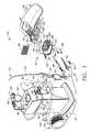
- FIG. 1is an isometric view of a biopsy system including a control module remotely coupled to a biopsy device, and including a localization fixture with a lateral grid plate used in conjunction with a rotatable cube to position a trocar/obturator or a probe of the biopsy device to a desired insertion depth as set by a ring stop.
- FIG. 2is an isometric view of the breast coil receiving the localization fixture of FIG. 1 .
- FIG. 3is an isometric view of the biopsy device inserted through the rotatable cube within the cube plate of the localization fixture attached to a breast coil of FIG. 1 .
- FIG. 4is an isometric view of a two-axis rotatable guide cube of the biopsy system of FIG. 1 .
- FIG. 5is a diagram of nine guide positions achievable by the two-axis rotatable guide cube of FIG. 5 .
- FIG. 6is an isometric view of a two-axis rotatable guide cube inserted into a lateral grid with the backing of the localization fixture of FIG. 1 .
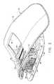
- FIG. 7is an isometric view of the trocar and sleeve of the biopsy system of FIG. 1 .
- FIG. 8is an isometric exploded view of the trocar and sleeve of FIG. 7 .
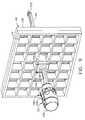
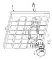
- FIG. 9is an isometric view of a trocar and sleeve of FIG. 7 with a depth stop device of FIG. 1 inserted through the guide cube and grid plate of FIG. 6 .
- FIG. 10is an alternative guide cube for the biopsy system of FIG. 1 with two-axes of rotation and self-grounding features.
- FIG. 11is an isometric view of the trocar and sleeve of FIG. 7 inserted into one of two guide cubes of FIG. 10 inserted into the grid plate of FIG. 1 .
- FIG. 12is an aft isometric view of a further alternative guide cube with four angled, parallel guide holes for the biopsy system of FIG. 1 .
- FIG. 13is a front isometric view of the guide cube of FIG. 12 .
- FIG. 14is a right side view of the guide cube of FIG. 12 with the angled, parallel guide holes depicted in phantom.
- FIG. 15is an aft view in elevation of yet another alternative guide cube for the biopsy system of FIG. 1 with a pair of converging guide holes and a pair of diverging guide holes.
- FIG. 16is a left side view of the guide cube of FIG. 15 taken in cross section along lines 16 - 16 through the pair of converging guide holes.
- FIG. 17is a left side view of the guide cube of FIG. 15 taken in cross section along lines 17 - 17 through the pair of diverging guide holes.
- FIG. 18is an isometric view of a two hole guide cube for the biopsy system of FIG. 1 .
- FIG. 19is an isometric view of a one-hole guide cube for the biopsy system of FIG. 1 .
- FIG. 20is a rotating guide for guiding the trocar and sleeve of FIG. 7 into either of the two-hole guide cube of FIG. 18 or the one-hole guide cube of FIG. 19 .
- FIG. 21is an aft isometric view of the trocar and sleeve of FIG. 7 inserted through the rotating guide of FIG. 20 into the two-hole guide cube of FIG. 18 .
- FIG. 22is an isometric locking O-ring for the biopsy system of FIG. 1 .
- FIG. 23is an aft view of the locking O-ring of FIG. 22 with a cross section of a biopsy instrument cannula shown in both an unlocked orientation and rotated a quarter turn into a locked orientation depicted in phanton.
- FIG. 24is an isometric view of a cylindrical rotating guide formed of elastomeric material with an oval through hole for the biopsy system of FIG. 1 .
- FIG. 25is an aft view of the cylindrical rotating guide of FIG. 24 with a cross sectional view of an unlocked oval-shaped biopsy instrument cannula inserted in the oval through hole.
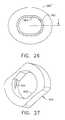
- FIG. 26is an aft view of the cylindrical rotating guide and biopsy instrument cannula of FIG. 25 with the cylindrical rotating guide rotated a quarter turn relative to the cannula to elastomerically lock thereon.
- FIG. 27is an isometric view of a flattened oval rotating guide for the biopsy system of FIG. 1 .
- FIG. 28is an isometric view of a triangular clip depth stop for the biopsy system of FIG. 1 .
- FIG. 29is an isometric view of a scissor-like depth stop clip for the biopsy system of FIG. 1 .
- FIG. 30is an aft isometric view of a shutter depth stop with an inserted biopsy instrument cannula for the biopsy system of FIG. 1 .
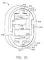
- FIG. 31is an aft view of the shutter depth stop of FIG. 30 prior to use.
- FIG. 32is a front isometric view of the shutter depth stop and inserted biopsy instrument cannula of FIG. 30 .
- FIG. 33is an aft view of the shutter depth stop and biopsy instrument cannula of FIG. 30 with the shutter depth stop vertically compressed into an unlocked state.
- a Magnetic Resonance Imaging (MRI) compatible biopsy system 10has a control module 12 that typically is placed outside of a shielded room containing an MRI machine (not shown) or at least spaced away to mitigate detrimental interaction with its strong magnetic field and/or sensitive radio frequency (RF) signal detection antennas.
- MRIMagnetic Resonance Imaging
- RFradio frequency
- the control module 12controls and powers an MRI biopsy device 14 that is positioned and guided by a localization fixture 16 attached to a breast coil 18 that is placed upon a gantry (not shown) of the MRI machine.
- the control module 12is mechanically, electrically, and pneumatically coupled to the MRI biopsy device 14 so that components may be segregated that need to be spaced away from the strong magnetic field and the sensitive RF receiving components of the MRI machine.
- a cable management spool 20is placed upon a cable management attachment saddle 22 that projects from a side of the control module 12 . Wound upon the cable management spool 20 is a paired electrical cable 24 and mechanical cable 26 for communicating control signals and cutter rotation/advancement motions respectively.
- electrical and mechanical cables 24 , 26each have one end connected to respective electrical and mechanical ports 28 , 30 in the control module 12 and another end connected to a reusable holster portion 32 of the MRI biopsy device 14 .
- An MRI docking cup 34which may hold the holster portion 32 when not in use, is hooked to the control module 12 by a docking station mounting bracket 36 .
- An interface lock box 38 mounted to a wallprovides a tether 40 to a lockout port 42 on the control module 12 .
- the tether 40is advantageously uniquely terminated and of short length to preclude inadvertent positioning of the control module 12 too close to the MRI machine.
- An in-line enclosure 44may advantageously register the tether 40 , electrical cable 24 and mechanical cable 26 to their respective ports 42 , 28 , 30 on the control module 12 .
- Vacuum assistis provided by a first vacuum line 46 that connects between the control module 12 and an outlet port 48 of a vacuum canister 50 that catches liquid and solid debris.
- a tubing kit 52completes the pneumatic communication between the control module 12 and the MRI biopsy device 14 .
- a second vacuum line 54is connected to an inlet port 56 of the vacuum canister 50 .
- the second vacuum line 54divides into two vacuum lines 58 , 60 that are attached to the MRI biopsy device 14 .
- the control module 12performs a functional check. Saline is manually injected into biopsy device 14 to serve as a lubricant and to assist in achieving a vacuum seal.
- the control module 12actuates a cutter mechanism (not shown) in the MRI biopsy device 14 , monitoring full travel. Binding in the mechanical cable 26 or within the biopsy device 14 is monitored with reference to motor force exerted to turn the mechanical cable 26 and/or an amount of twist in the mechanical cable 26 sensed in comparing rotary speed or position at each end of the mechanical cable 26 .
- a remote keypad 62which is detachable from the reusable holster portion 32 , communicates via the electrical cable 24 to the control panel 12 to enhance clinician control of the MRI biopsy device 14 , especially when controls that would otherwise be on the MRI biopsy device 14 itself are not readily accessible after insertion into the localization fixture 16 and/or placement of the control module 12 is inconveniently remote (e.g., 30 feet away).
- An aft end thumbwheel 63 on the reusable holster portion 32is also readily accessible after insertion to rotate the side from which a tissue sample is to be taken.
- Left and right parallel upper guides 64 , 66 of a localization framework 68are laterally adjustably received respectively within left and right parallel upper tracks 70 , 72 attached to an under side 74 and to each side of a selected breast aperture 76 formed in a patient support platform 78 of the breast coil 18 .
- a base 80 of the breast coil 18is connected by centerline pillars 82 that are attached to the patient support platform 78 between the breast apertures 76 .
- a pair of outer vertical support pillars 84 , 86 on each side spaced about a respective breast aperture 76respectively define a lateral recess 88 within which the localization fixture 16 resides.
- the patient's breastshang pendulously respectively into the breast apertures 76 within the lateral recesses 88 .
- a conventionis used for locating a suspicious lesion by Cartesian coordinates within breast tissue referenced to the localization fixture 16 and to thereafter selectively position an instrument, such as a probe 90 ( FIG. 1 ) of a disposable probe assembly 91 that is engaged to the reusable holster portion 32 to form the MRI biopsy device 14 .
- the MRI compatible biopsy system 10may also guide a trocar (“introducer”) 92 encompassed by a sleeve 94 . Depth of insertion is controlled by a depth stop device 95 longitudinally positioned on either the probe 90 or the sleeve 94 .
- a lateral fencedepicted as a grid plate 96
- a laterally adjustable outer three sided plate bracket 98attached below the left and right parallel upper guides 64 , 66 .
- a medial fence with respect to a medial plane of the chest of the patientdepicted as a medial plate 100
- an inner three-sided plate bracket 102attached below the left and right parallel upper guides 64 , 66 close to the centerline pillars 82 when installed in the breast coil 18 .
- a guide cube 104is inserted into the backside of the grid plate 96 .
- the selected breastis compressed along an inner (medial) side by the medial plate 100 and on an outside (lateral) side of the breast by the grid plate 96 , the latter defining an X-Y plane.
- the X-axisis vertical (sagittal) with respect to a standing patient and corresponds to a left to right axis as viewed by a clinician facing the externally exposed portion of the localization fixture 16 .
- Perpendicular to this X-Y plane extending toward the medial side of the breastis the Z-axis, which typically corresponds to the orientation and depth of insertion of the probe 90 of the MRI biopsy device 14 or the trocar/sleeve 92 , 94 .
- Z-axismay be used interchangeably with “axis of penetration”, although the latter may or may not be orthogonal to the spatial coordinates used to locate an insertion point on the patient.
- Versions of the localization fixture 16 described hereinallow a nonorthogonal axis of penetration to the X-Y axis to a lesion at a convenient or clinically beneficial angle.
- guide cube 104includes a central guide hole 106 , a corner guide hole 108 , and an off-center guide hole 110 that pass orthogonally to one another between respective opposite pairs of faces 112 , 114 , 116 .
- guide cube 104By selectively rotating the guide cube 104 in two axis, one of the pairs of faces 112 , 114 , 116 may be proximally aligned to an unturned position and then the selected proximal face 112 , 114 , 116 optionally rotated a quarter turn, half turn, or three quarter turn.
- one of nine guide positions 118i.e., using central guide hole 106
- 120 a - 120 di.e., corner guide hole 108
- 122 a - 122 di.e., using off-center guide hole 110
- FIG. 5one of nine guide positions 118 (i.e., using central guide hole 106 ), 120 a - 120 d (i.e., corner guide hole 108 ), 122 a - 122 d (i.e., using off-center guide hole 110 ) may be proximally exposed as depicted in FIG. 5 .
- the two-axis rotatable guide cube 104is sized for insertion from a proximal side into one of a plurality of square recesses 130 in the grid plate 96 formed by intersecting vertical bars 132 and horizontal bars 134 .
- the guide cube 104is prevented from passing through the grid plate 96 by a backing substrate 136 attached to a front face of the grid plate 96 .
- the backing substrate 136includes a respective square opening 138 centered within each square recess 130 , forming a lip 140 sufficient to capture the front face of the guide cube 104 but not so large as to obstruct the guide holes 104 , 106 , 108 .
- the depth of the square recesses 130is less than the guide cube 104 , thereby exposing a proximal portion 142 of the guide cube 104 for seizing and extraction from the grid plate 96 .
- the trocar 92is slid into the sleeve 94 and the combination is guided through the guide cube 104 ( FIG. 9 ) to the biopsy site within the breast tissue.
- the sleeve 94includes a hollow shaft (or cannula) 196 that is proximally attached to a cylindrical hub 198 and has a lateral aperture 200 proximate to an open distal end 202 .
- the cylindrical hub 198has an exteriorly presented thumbwheel 204 for rotating the lateral aperture 200 .
- the cylindrical hub 198has an interior recess 206 that encompasses a duckbill seal 208 , wiper seal 210 and a seal retainer 212 to provide a fluid seal when the shaft 196 is empty and for sealing to the inserted introducer (trocar) 92 .
- Longitudinally spaced measurement indicia 213 along an outer surface of the hollow shaft 196visually, and perhaps physically, provide a means to locate the depth stop device 95 of FIG. 1 .
- a hollow shaft 214includes a fluid lumen 216 that communicates between an imagable side notch 218 and a proximal port 220 .
- the hollow shaft 214is longitudinally sized to extend, when fully engaged, a piercing tip 222 out of the distal end 202 of the sleeve 94 .
- An obturator thumbwheel cap 224encompasses the proximal port 220 and includes a locking feature 226 , which includes a visible angle indicator 228 ( FIG.
- the obturator seal cap 230may be engaged proximally into the obturator thumbwheel cap 224 to close the fluid lumen 216 .
- the obturator seal cap 230includes a locking or locating feature 232 that includes a visible angle indicator 233 that corresponds with the visible angle indicator 228 on the obturator thumbwheel cap 224 , which may be fashioned from either a rigid, soft, or elastomeric material.
- the guide cube 104has guided the trocar 92 and sleeve 94 through the grid plate 96 .
- an alternative guide cube 104 ahas rotation in two axes but is self grounding by means of an added rectangular prism 240 which has a shared edge with a cubic portion 242 of the guide cube 104 a .
- a larger square face 244 of the cubic portion 242overlaps with a smaller square face 246 of the rectangular prism 240 to correspond with the desired size of an exposed proximal portion 248 of the inserted guide cube 104 a .
- the rectangular prism 240allows proximal exposure of one of two adjacent faces 250 , 252 of the guide cube 104 a and then turning each to one of four quarter turn rotational positions.
- first face 250has a central guide hole 106 a and the second face 252 has a corner guide hole 108 a , and an off-center guide hole 110 a .
- a radial recess 254is relieved into the rectangular prism 240 to allow grounding of the depth stop device 95 against the face 252 when the off-center guide hole 110 a is used.
- another alternative guide cube 104 bhas a proximal enlarged hat portion 270 about a proximal face 271 that grounds against the selected square recess 130 in the grid plate 96 ( FIG. 6 ) and allows rotation about one axis to one of four quarter turn positions.
- Four angled guide holes 272 a , 272 b , 272 c , 272 dallow accessing not only an increased number of insertion points within the selected square recess 130 but also a desired angle of penetration rather than being constrained to a perpendicular insertion.
- an additional alternative guide cube 104 calso has the proximal enlarged hat portion 270 about the proximal face 271 that grounds against the selected square recess 130 in the grid plate 96 ( FIG. 6 ) and allows rotation about one axis to one of four quarter turn positions.
- the guide holesare depicted as a first pair of converging angled through holes 310 a , 310 b having outwardly spaced proximal openings 311 a , 311 b ( FIG. 15 ), respectively, that communicate with partially intersecting distal openings 312 a , 312 b , respectively.
- the guide holesare also depicted as a second pair of diverging angled through holes 310 c , 310 d having partially intersecting proximal openings 311 c , 311 d , respectively, that communicate with outwardly spaced distal openings 312 c , 312 d.
- a further alternative two-hole guide cube 104 dhas two enlarged guide holes 330 , 332 accessed through the proximal face 271 in the enlarged proximal hat portion 270 .
- a one hole guide cube 104 ehas one enlarged guide hole 334 accessed through the proximal face 271 in the enlarged proximal hat portion 270 .
- Each guide cube 104 d , 104 emay receive a cylindrical rotating guide 336 ( FIG. 20 ) with an integral, proximal depth ring stop 338 .
- a through hole 340 in the cylindrical guide 336is sized to receive a biopsy instrument cannula (e.g., probe 90 , sleeve 94 ) by being oval in cross section in the illustrative version.
- a biopsy instrument cannulae.g., probe 90 , sleeve 94
- the cylindrical guide 336may provide structural support to the guided portion of the biopsy instrument support as well as facilitate axial rotation thereof, especially for a non cylindrical biopsy instrument cannula.
- the two-hole and one-hole guide cubes 104 d , 104 e and rotating guide 336may comprise a guide cube set, perhaps with additional guide cubes (not shown) having uniquely positioned guide holes.
- additional guide cubesnot shown
- too much overlap of guide holesmay result in insufficient support by the rotating guide 336 for the inserted biopsy instrument cannula.
- fine positioningis accomplished by selecting one of the available guide cubes 104 d , 104 e for the desired position within a selected grid aperture.
- a locking O-ring featuremay be advantageously incorporated into a depth ring stop (rotating guide) 350 .
- Having to rely upon constant frictional engagement of the depth ring stop (rotating guide) 350 alonewould result in difficulty in installing the ring stop 350 to the desired position or being too readily displaced to serve as a stopping structure.
- an outer circumference surface 351 of the ring stop 350includes left and right outer longitudinal ridges 352 , 354 that aid in gripping and orienting the depth ring stop 350 while turning for locking and unlocking.
- opposing inner longitudinal ridges 356 , 358 formed in a generally cylindrical inner diameter 359abut respectively at an upper left and lower right side of an oval cannula 360 ( FIG. 23 ) oriented with its elongate cross section vertically in an unlocked position.
- the inner longitudinal ridges 356 , 358allow a quarter turn clockwise of the oval cannula, depicted as 360 ′, to a locked position deforming an inner tangential locking rib 362 .
- a cylindrical rotating guide 380formed of a resilient polymer, has an elongate through hole 382 shaped to permit insertion of an oval biopsy cannula 384 .
- FIG. 24-25a cylindrical rotating guide 380 , formed of a resilient polymer, has an elongate through hole 382 shaped to permit insertion of an oval biopsy cannula 384 .
- a rotating guide 400is oval shaped with flattened elongate sides and with a corresponding elongate through hole 402 .
- the outer shapemay be tactile, advantageous for gripping as well as for providing a visual indication of being locked or unlocked.
- a resilient tangential rib 404 crossing one inner corner of the elongate through hole 402is positioned to bind against an inserted biopsy instrument cannula (not shown) when the rotating guide 400 is turned a quarter turn to a locking position.
- a triangular clip depth stop 420has a transverse front surface 422 with a proximally turned lower lip 424 and an upper lateral edge 426 attached to a downwardly and proximally ramped member 428 whose lower lateral edge 430 bends distally to form a horizontal locking actuator member 432 whose distal edge 434 rests upon the lower lip 424 .
- a front vertically elongate aperture 436 in the transverse front surface 422is shaped to approximate the outer diameter of an inserted biopsy instrument cannula (not shown).
- An aft elongate aperture 438 formed in the downwardly and proximally ramped member 428is a distal horizontal projection of the front vertically elongate aperture 436 when the locking actuator member 432 is upwardly raised, thus allowing insertion of the biopsy instrument cannula through both apertures 436 , 438 .
- an upper inner surface 440 of the aft elongate aperture 438lowers, binding upon the inserted biopsy instrument cannula, allowing the transverse front surface 422 to serve as a positive depth stop.
- a scissor-like clip depth stop 450is cut out of a layer of resilient material.
- an upper arm portion 452 and a lower arm portion 454are attached to one radiating vertically away from each other toward the same lateral side (right as depicted) from a split cylindrical grasping portion 456 separated longitudinally on a lateral side opposite to the arm portions 452 , 454 (left as depicted).
- an upper gripping half-cylindrical member 458is attached at its right side to a lower portion 460 of the upper arm portion 452 .
- a lower gripping half-cylindrical member 462is attached at its right side to an upper portion 464 of the lower arm portion 454 .
- An upper hemispheric portion 466 of the upper arm portion 452includes an upper finger hole 468 .
- a lower hemispheric portion 470 of the lower arm portion 454includes a lower finger hole 472 .
- a triangular recess 474(opening rightward as depicted) formed by the arm portions 452 , 454 and a longitudinal pin 476 inserted at the juncture between the arm portions 452 , 454 predispose the arm portions 452 , 454 to be resiliently drawn toward each other as the finger holes 468 , 472 are gripped and moved together, thereby opening the upper and lower gripping half cylindrical members 458 , 462 , widening the separation of their left ends.
- a biopsy instrument cannula(not shown) may be inserted and positioned to a desired depth.
- a shuttered depth stop 600includes a resilient oval shell 602 with a corresponding oval aperture 604 with an upper right tab 606 projecting inwardly to the left and with a lower left tab 608 projecting inwardly to the right when viewed from behind ( FIG. 30 ).
- An upper resilient member 610has a generally horseshoe-shaped outer surface 612 that conforms to an upper portion 614 of the oval aperture 604 .
- a lower resilient member 616has a generally horseshoe-shaped outer surface 618 that conforms to a lower portion 620 of the oval aperture 604 .
- the upper and lower resilient members 610 , 616are identical but are rotated a half turn about a longitudinal axis with respect to each other.
- the entire shuttered depth stop 600is symmetric about its vertical axis defined by its longest dimension or about a horizontal axis defined by its second longest dimension.
- a downwardly open rectangular prismatic recess 622 formed in the upper resilient member 610is sized to receive an upper shutter 624 having an upper center tab 626 and a lower acute edge 628 .
- a top center rectangular slot 630 formed in the upper resilient member 610communicates with the downwardly open rectangular prismatic recess 622 and receives the upper center tab 626 .
- An upwardly open rectangular prismatic recess 632 formed in the lower resilient member 616is sized to receive a lower shutter 634 having a lower center tab 636 and an upper acute edge 638 .
- a bottom center rectangular slot 639 formed in the lower resilient member 616communicates with the upwardly open rectangular prismatic recess 632 and receives the lower center tab 636 .
- An upper horizontal pin 640 attached horizontally as depicted across the upper shutter 624is received for rotation onto opposite lateral sides of the downwardly open rectangular prismatic recess 622 .
- a lower horizontal pin 642 attached horizontally as depicted across the lower shutter 634is received for rotation onto opposite lateral sides of the upwardly open rectangular prismatic recess 632 .
- the right side of the upper resilient member 610includes a right outward shoulder 644 that rests upon the upper right tab 606 of the resilient oval shell 602 .
- a laterally recessed downward arm 646is attached to the right shoulder 644 and extends downwardly with its outer surface 648 vertically aligned with an innermost edge 650 of the right outward shoulder 644 and with its inner surface 652 defining the downwardly open generally rectangular prismatic recess 622 .
- the left side of the upper resilient member 610includes a left inward shoulder 654 that is laterally aligned with and opposite of the upper right tab 606 of the resilient oval shell 602 .
- An outer downward arm 656is attached to the left inward shoulder 654 and extends downwardly with its outer surface 658 against oval aperture 604 and an innermost edge 660 vertically aligned with an inner surface 662 of the lower left tab 608 upon which the outer downward arm 656 rests.
- the lower resilient member 616includes a left outward shoulder 664 attached to a laterally recessed upward arm 666 and a right inward shoulder 668 attached to an outer upward arm 670 that abuts an underside of the upper right tab 606 .
- the laterally recessed downward arm 646 of the upper resilient member 610extends downward past the longitudinal centerline of the shuttered depth stop 600 and an inserted biopsy instrument cannula 672 .
- a lower edge 674 of the laterally recessed downward arm 646is spaced away from an upper surface 676 of the right inward shoulder 668 .
- an upper edge 678 of the laterally recessed upward arm 666is spaced away from a lower surface 680 of the left inward shoulder 654 .
- this spacing between the left inward shoulder 654 and the upper edge 678 of the laterally recessed upward arm 666defines an upper left rectangular recess 682 communicating rightward into the downwardly open rectangular prismatic recess 622 and sized to allow unimpeded swinging of a leftward extension 684 of the upper shutter 624 .
- Spacing between the upper surface 676 of the right inward shoulder 668 and the lower edge 674 of the laterally recessed downward arm 646defines a lower right rectangular recess 686 which communicates leftward into the upwardly open rectangular prismatic recess 632 which is sized to allow unimpeded swinging of a rightward extension 688 of the lower shutter 634 .
- the shuttered depth stop 600initially has closed upper and lower shutters 624 , 634 due to restoring pressure from the top center rectangular slot 630 on the upper center tab 626 and from the bottom center rectangular slot 639 on the lower center tab 636 respectively. Insertion of a biopsy instrument cannula 672 from a selected side (thus the aft side) causes the upper and lower acute edges 628 , 638 of the shutters 624 , 634 to swing distally and outwardly but remain in contact due to the restoring pressure previously mentioned.
- Proximal retraction of the biopsy instrument cannula 672frictionally rotates the acute edges 628 , 638 proximally, and thus inwardly, binding upon the biopsy instrument cannula 672 preventing inadvertent retraction to serve as a depth stop.
- squeezing the resilient oval shell 602 to reduce the vertical height of the shutter depth stop 600 in FIG. 33causes the laterally recessed downward arm 646 to open the lower shutter 634 and the laterally recessed upward arm 666 to open the upper shutter 624 .
- a single shuttermay be employed in a shuttered depth stop consistent with aspects of the invention.
- grooves in the biopsy cannulamay enhance engagement of one or two shutters to further avoid inadvertent proximal retraction of the positioned shuttered depth stop.
- the grooves on the biopsy cannulamay be ramped such that engagement is more prevalent against proximal retraction as compared to distal positioning. Further, such grooves may be along only a portion of the circumference of the biopsy cannula such that rotation of the shuttered depth stop also further unlocks from the biopsy cannula for positioning.
- straight upper and lower acute edges 628 , 638 of the two shutters 624 , 634may instead be contoured to closely approximate the transverse cross section of the encompassed shuttered depth stop 600 to increase the locking against inadvertent retraction.
- imaging modalitiesmay benefit from aspects of the present invention.
- a grid plate 96 with a backing lip 140may be used such that a guide cube rotatable to each of the six faces with four quarter turn positions for each face may achieve a large number of possible insertion positions and angles of insertion.
- biasing of the locking/unlocking components of various versions of a depth stop for a biopsy cannula described hereinare advantageously formed out of an elastomeric material for economical manufacture.
- an assembly of rigid components biased by springs for biasing and/or actuating controls to move the locking surface out of engagementmay be substituted to achieve similar results consistent with aspects of the present invention.
- the positioning and height of a central web of a breast coilmay enable use of a medial grid plate used with a rotatable cube and penetrate from the medial side of the breast.
- a grid having a different geometric shape, such as hexagonalmay be employed.
- each grid aperture of equilateral polygonal lateral cross section in a grid platetaper toward their distal opening to ground a similarly tapered guide block.
Landscapes
- Health & Medical Sciences (AREA)
- Life Sciences & Earth Sciences (AREA)
- Surgery (AREA)
- General Health & Medical Sciences (AREA)
- Veterinary Medicine (AREA)
- Heart & Thoracic Surgery (AREA)
- Medical Informatics (AREA)
- Molecular Biology (AREA)
- Engineering & Computer Science (AREA)
- Animal Behavior & Ethology (AREA)
- Pathology (AREA)
- Public Health (AREA)
- Biomedical Technology (AREA)
- Nuclear Medicine, Radiotherapy & Molecular Imaging (AREA)
- Oncology (AREA)
- Physics & Mathematics (AREA)
- Biophysics (AREA)
- Surgical Instruments (AREA)
- Magnetic Resonance Imaging Apparatus (AREA)
- High Energy & Nuclear Physics (AREA)
- Radiology & Medical Imaging (AREA)
Abstract
Description
Claims (19)
Priority Applications (2)
| Application Number | Priority Date | Filing Date | Title |
|---|---|---|---|
| US12/368,317US9433401B2 (en) | 2006-05-01 | 2009-02-10 | Biopsy cannula adjustable depth stop |
| US15/214,068US10327805B2 (en) | 2006-05-01 | 2016-07-19 | Biopsy cannula adjustable depth stop |
Applications Claiming Priority (2)
| Application Number | Priority Date | Filing Date | Title |
|---|---|---|---|
| US11/414,988US7507210B2 (en) | 2006-05-01 | 2006-05-01 | Biopsy cannula adjustable depth stop |
| US12/368,317US9433401B2 (en) | 2006-05-01 | 2009-02-10 | Biopsy cannula adjustable depth stop |
Related Parent Applications (1)
| Application Number | Title | Priority Date | Filing Date |
|---|---|---|---|
| US11/414,988DivisionUS7507210B2 (en) | 2006-05-01 | 2006-05-01 | Biopsy cannula adjustable depth stop |
Related Child Applications (1)
| Application Number | Title | Priority Date | Filing Date |
|---|---|---|---|
| US15/214,068ContinuationUS10327805B2 (en) | 2006-05-01 | 2016-07-19 | Biopsy cannula adjustable depth stop |
Publications (2)
| Publication Number | Publication Date |
|---|---|
| US20090163830A1 US20090163830A1 (en) | 2009-06-25 |
| US9433401B2true US9433401B2 (en) | 2016-09-06 |
Family
ID=38283261
Family Applications (3)
| Application Number | Title | Priority Date | Filing Date |
|---|---|---|---|
| US11/414,988Expired - Fee RelatedUS7507210B2 (en) | 2006-05-01 | 2006-05-01 | Biopsy cannula adjustable depth stop |
| US12/368,317Expired - Fee RelatedUS9433401B2 (en) | 2006-05-01 | 2009-02-10 | Biopsy cannula adjustable depth stop |
| US15/214,068Active2026-08-27US10327805B2 (en) | 2006-05-01 | 2016-07-19 | Biopsy cannula adjustable depth stop |
Family Applications Before (1)
| Application Number | Title | Priority Date | Filing Date |
|---|---|---|---|
| US11/414,988Expired - Fee RelatedUS7507210B2 (en) | 2006-05-01 | 2006-05-01 | Biopsy cannula adjustable depth stop |
Family Applications After (1)
| Application Number | Title | Priority Date | Filing Date |
|---|---|---|---|
| US15/214,068Active2026-08-27US10327805B2 (en) | 2006-05-01 | 2016-07-19 | Biopsy cannula adjustable depth stop |
Country Status (8)
| Country | Link |
|---|---|
| US (3) | US7507210B2 (en) |
| EP (3) | EP2111799B1 (en) |
| JP (3) | JP5165920B2 (en) |
| CN (1) | CN101066214B (en) |
| AU (1) | AU2007201670B2 (en) |
| CA (2) | CA2586504C (en) |
| DE (1) | DE602007001999D1 (en) |
| HK (1) | HK1248506A1 (en) |
Cited By (1)
| Publication number | Priority date | Publication date | Assignee | Title |
|---|---|---|---|---|
| US20160324540A1 (en)* | 2006-05-01 | 2016-11-10 | Devicor Medical Products, Inc. | Biopsy cannula adjustable depth stop |
Families Citing this family (94)
| Publication number | Priority date | Publication date | Assignee | Title |
|---|---|---|---|---|
| US7379769B2 (en) | 2003-09-30 | 2008-05-27 | Sunnybrook Health Sciences Center | Hybrid imaging method to monitor medical device delivery and patient support for use in the method |
| US7740593B2 (en) | 2005-12-09 | 2010-06-22 | Senorx, Inc | Guide block for biopsy or surgical devices |
| US8579807B2 (en) | 2008-04-28 | 2013-11-12 | Ethicon Endo-Surgery, Inc. | Absorbing fluids in a surgical access device |
| US8702623B2 (en) | 2008-12-18 | 2014-04-22 | Devicor Medical Products, Inc. | Biopsy device with discrete tissue chambers |
| US20140039343A1 (en) | 2006-12-13 | 2014-02-06 | Devicor Medical Products, Inc. | Biopsy system |
| US8374676B2 (en)* | 2007-11-23 | 2013-02-12 | Hologic, Inc. | Chest wall coil array for breast imaging |
| US7940047B2 (en) | 2007-11-23 | 2011-05-10 | Sentinelle Medical, Inc. | Microcontroller system for identifying RF coils in the bore of a magnetic resonance imaging system |
| US20090209853A1 (en)* | 2008-02-19 | 2009-08-20 | Parihar Shailendra K | Biopsy site marker applier |
| US8532748B2 (en) | 2008-04-23 | 2013-09-10 | Devicor Medical Products, Inc. | Devices useful in imaging |
| US20090270726A1 (en)* | 2008-04-23 | 2009-10-29 | Leimbach Jessica P | Methods For Imaging |
| AU2009201610A1 (en) | 2008-04-23 | 2009-11-19 | Devicor Medical Products, Inc. | PEM and BSGI biopsy devices and methods |
| US8864681B2 (en)* | 2008-04-23 | 2014-10-21 | Devicor Medical Products, Inc. | Biopsy devices |
| USD700326S1 (en) | 2008-04-28 | 2014-02-25 | Ethicon Endo-Surgery, Inc. | Trocar housing |
| US9358041B2 (en) | 2008-04-28 | 2016-06-07 | Ethicon Endo-Surgery, Llc | Wicking fluid management in a surgical access device |
| US8568362B2 (en) | 2008-04-28 | 2013-10-29 | Ethicon Endo-Surgery, Inc. | Surgical access device with sorbents |
| US11235111B2 (en) | 2008-04-28 | 2022-02-01 | Ethicon Llc | Surgical access device |
| US8636686B2 (en) | 2008-04-28 | 2014-01-28 | Ethicon Endo-Surgery, Inc. | Surgical access device |
| US8870747B2 (en)* | 2008-04-28 | 2014-10-28 | Ethicon Endo-Surgery, Inc. | Scraping fluid removal in a surgical access device |
| US8273060B2 (en) | 2008-04-28 | 2012-09-25 | Ethicon Endo-Surgery, Inc. | Fluid removal in a surgical access device |
| US20090292224A1 (en)* | 2008-05-22 | 2009-11-26 | Bowman Bryan J | Positioning mechanism for an introducer device |
| US8057432B2 (en)* | 2008-05-22 | 2011-11-15 | Suros Surgical Systems, Inc. | Selective locking mechanism for an introducer device |
| US7730628B2 (en)* | 2008-09-05 | 2010-06-08 | Bayer Schering Pharma Ag | Depth stop devices and systems |
| US8167815B2 (en)* | 2008-12-18 | 2012-05-01 | Devicor Medical Products, Inc. | Biopsy device with retractable cutter |
| US20100160811A1 (en)* | 2008-12-18 | 2010-06-24 | Parihar Shailendra K | Z-Stop Feature of Targeting Set for MRI Biopsy Device |
| US20100160822A1 (en)* | 2008-12-18 | 2010-06-24 | Parihar Shailendra K | Biopsy Device with Detachable Needle |
| US9398922B2 (en) | 2008-12-18 | 2016-07-26 | Devicor Medical Products, Inc. | Targeting set for MRI biopsy device with probe holster support |
| US8460206B2 (en)* | 2008-12-18 | 2013-06-11 | Devicor Medical Products, Inc. | Multi-orientation targeting set for MRI biopsy device |
| US7846109B2 (en)* | 2008-12-18 | 2010-12-07 | Devicor Medical Products, Inc. | Biopsy device with sliding cutter cover |
| US7862518B2 (en)* | 2008-12-18 | 2011-01-04 | Devicor Medical Products, Inc. | Biopsy device with telescoping cutter cover |
| US8328732B2 (en) | 2008-12-18 | 2012-12-11 | Devicor Medical Products, Inc. | Control module interface for MRI biopsy device |
| US8366635B2 (en) | 2008-12-18 | 2013-02-05 | Devicor Medical Products, Inc. | Biopsy probe and targeting set interface |
| WO2010102087A1 (en)* | 2009-03-06 | 2010-09-10 | Hologic, Inc. | Needle biopsy compression paddle system and method of use |
| US8366634B2 (en)* | 2009-06-16 | 2013-02-05 | Devicor Medical Products, Inc. | Biopsy targeting cube with elastomeric body |
| US8197495B2 (en)* | 2009-06-16 | 2012-06-12 | Devicor Medical Products, Inc. | Biopsy targeting cube with elastomeric edges |
| US8167814B2 (en)* | 2009-06-16 | 2012-05-01 | Devicor Medical Products, Inc. | Biopsy targeting cube with malleable members |
| US8858537B2 (en) | 2009-06-16 | 2014-10-14 | Devicor Medical Products, Inc. | Biopsy targeting cube with living hinges |
| US8241302B2 (en)* | 2009-06-16 | 2012-08-14 | Devicor Medical Products, Inc. | Biopsy targeting cube with angled interface |
| US20100324444A1 (en)* | 2009-06-17 | 2010-12-23 | Mollere Rebecca J | MRI Biopsy Targeting Grid Wall Guide |
| US8206314B2 (en) | 2009-06-17 | 2012-06-26 | Devicor Medical Products, Inc. | MRI biopsy targeting grid with round openings |
| US20100324445A1 (en) | 2009-06-17 | 2010-12-23 | Mollere Rebecca J | MRI Biopsy Cylindraceous Targeting Guide |
| US8747331B2 (en)* | 2009-06-23 | 2014-06-10 | Hologic, Inc. | Variable angle guide holder for a biopsy guide plug |
| US20110071391A1 (en)* | 2009-09-24 | 2011-03-24 | Speeg Trevor W V | Biopsy marker delivery device with positioning component |
| US8529465B2 (en)* | 2009-09-24 | 2013-09-10 | Devicor Medical Products, Inc. | Biopsy marker delivery devices and methods |
| US20110082364A1 (en)* | 2009-10-05 | 2011-04-07 | Hibner John A | MRI Biopsy Targeting Cube with Retention Wiper |
| US8162848B2 (en)* | 2009-10-16 | 2012-04-24 | Devicor Medical Products, Inc. | MRI biopsy targeting cube with eccentric lock |
| US8162849B2 (en)* | 2009-10-16 | 2012-04-24 | Devicor Medical Products, Inc. | MRI biopsy targeting cube with gripping arms |
| US20110092850A1 (en)* | 2009-10-16 | 2011-04-21 | Kulkarni Abhijit G | MRI Biopsy Targeting Guide with Rotational Lock |
| US8162847B2 (en)* | 2009-10-16 | 2012-04-24 | Devicor Medical Products, Inc. | MRI biopsy targeting cube with snap corners |
| US9019262B2 (en)* | 2009-11-27 | 2015-04-28 | Hologic, Inc. | Systems and methods for tracking positions between imaging modalities and transforming a displayed three-dimensional image corresponding to a position and orientation of a probe |
| US8597201B2 (en) | 2010-03-30 | 2013-12-03 | Siteselect Medical Technologies, Inc. | Tissue excision device with a flexible transection blade |
| US9913596B2 (en) | 2010-11-25 | 2018-03-13 | Invivo Corporation | Systems and methods for MRI guided trans-orifice and transperineal intervention apparatus with adjustable biopsy needle insertion |
| US9414816B2 (en) | 2011-06-23 | 2016-08-16 | Devicor Medical Products, Inc. | Introducer for biopsy device |
| US10159456B2 (en) | 2011-11-22 | 2018-12-25 | Ge Medical Systems Israel, Ltd | Systems and methods for biopsy guidance using a biopsy unit including at least one of an imaging detector or ultrasound probe concurrently mounted with a biopsy guide |
| EP2838435B1 (en) | 2012-04-16 | 2020-03-25 | Hathaway, Jeff M. | Biopsy device |
| ES2924635T3 (en) | 2012-11-21 | 2022-10-10 | Bard Inc C R | Core needle biopsy device |
| USD735332S1 (en) | 2013-03-06 | 2015-07-28 | C. R. Bard, Inc. | Biopsy device |
| USD737440S1 (en) | 2013-03-07 | 2015-08-25 | C. R. Bard, Inc. | Biopsy device |
| US10092276B2 (en) | 2013-03-15 | 2018-10-09 | Cook Medical Technologies Llc | Tissue acquisition device with indication system |
| AU2014237346B2 (en) | 2013-03-15 | 2020-02-27 | Hologic, Inc. | System and method for reviewing and analyzing cytological specimens |
| USD735333S1 (en) | 2013-06-26 | 2015-07-28 | C. R. Bard, Inc. | Biopsy device |
| EP3021761B1 (en) | 2013-07-19 | 2020-03-18 | Devicor Medical Products, Inc. | Biopsy device targeting features |
| CN106456140B (en)* | 2014-05-01 | 2019-08-13 | 德威科医疗产品公司 | Introducer for Biopsy Devices |
| EP3148471B1 (en)* | 2014-05-28 | 2021-11-03 | General Electric Company | Method and associated biopsy device |
| US9974500B2 (en) | 2014-07-11 | 2018-05-22 | Ge Medical Systems Israel, Ltd. | Systems and methods for open imaging |
| EP3197370B1 (en) | 2014-09-24 | 2021-11-17 | Devicor Medical Products, Inc. | Mri biopsy system |
| WO2016179145A1 (en) | 2015-05-06 | 2016-11-10 | Devicor Medical Products, Inc. | Mri guided breast biopsy targeting assembly with obturator overshoot feature |
| US10646208B2 (en) | 2015-05-06 | 2020-05-12 | Devicor Medical Products, Inc. | Marker delivery device for use with MRI breast biopsy system |
| JP2018522627A (en) | 2015-06-11 | 2018-08-16 | デビコー・メディカル・プロダクツ・インコーポレイテッドDevicor Medical Products, Inc. | MRI biopsy system |
| WO2017019780A1 (en) | 2015-07-29 | 2017-02-02 | Devicor Medical Products, Inc. | Biopsy imaging rod with an egress port, with a biopsy marker and with a biased pushrod |
| EP3344153A1 (en) | 2015-08-31 | 2018-07-11 | Devicor Medical Products, Inc. | Multi-faceted needle tip |
| US10335124B1 (en) | 2016-02-29 | 2019-07-02 | Devicor Medical Products, Inc. | Marker delivery device with adaptor for biopsy site marking and method of use thereof |
| US20170311932A1 (en)* | 2016-04-29 | 2017-11-02 | Devicor Medical Products, Inc. | Depth stop device for use with biopsy targeting assembly |
| JP2019515740A (en) | 2016-04-29 | 2019-06-13 | デビコー・メディカル・プロダクツ・インコーポレイテッドDevicor Medical Products, Inc. | MRI-guided biopsy targeting set with launch obturator |
| US10729856B1 (en) | 2016-07-29 | 2020-08-04 | Devicor Medical Products, Inc. | Guide and filter for biopsy device |
| US10357326B1 (en)* | 2016-07-29 | 2019-07-23 | Devicor Medical Products, Inc. | MRI breast biopsy targeting grid and cube |
| US11160538B2 (en) | 2016-10-31 | 2021-11-02 | Devicor Medical Products, Inc. | Biopsy device with linear actuator |
| JP2020520738A (en) | 2017-05-22 | 2020-07-16 | デビコー・メディカル・プロダクツ・インコーポレイテッドDevicor Medical Products, Inc. | MRI target set with improved target sleeve |
| JP6984007B2 (en)* | 2017-09-20 | 2021-12-17 | デビコー・メディカル・プロダクツ・インコーポレイテッドDevicor Medical Products, Inc. | MRI Guided Biopsy Device with Rotating Depth Stop Device |
| JP2021503996A (en) | 2017-11-22 | 2021-02-15 | デビコー・メディカル・プロダクツ・インコーポレイテッドDevicor Medical Products, Inc. | Adjustable targeting set for MRI-induced biopsy procedures |
| EP3716861B1 (en) | 2017-11-30 | 2024-10-23 | C. R. Bard, Inc. | Sample container for a biopsy apparatus |
| US12186879B2 (en)* | 2018-01-18 | 2025-01-07 | Ingersoll-Rand Industrial U.S., Inc. | Add-on user interface module for precision power tools |
| WO2020014584A1 (en) | 2018-07-13 | 2020-01-16 | Devicor Medical Products, Inc. | Biopsy device with self-reversing cutter drive |
| US20200205855A1 (en)* | 2019-01-02 | 2020-07-02 | Covidien Lp | Surgical access device and sleeve stops for use therewith |
| US11344309B2 (en)* | 2019-07-05 | 2022-05-31 | Covidien Lp | Circular stapling instruments |
| CN112402029B (en)* | 2019-08-23 | 2025-08-19 | 深圳钮迈科技有限公司 | Front panel of tumor therapeutic apparatus, front panel assembly and tumor therapeutic apparatus |
| US11712267B2 (en) | 2020-05-01 | 2023-08-01 | Cilag Gmbh International | Tilting tang cannula depth limiter |
| US11980392B2 (en) | 2020-05-01 | 2024-05-14 | Cilag Gmbh International | Pinch-to-clamp cannula depth limiter |
| US11986215B2 (en) | 2020-05-01 | 2024-05-21 | Cilag Gmbh International | Universal size multi-walled elastomer cannula depth limiter |
| US12213699B2 (en) | 2020-05-01 | 2025-02-04 | Cilag Gmbh International | Threaded cannula depth limiter |
| US11633211B2 (en) | 2020-05-01 | 2023-04-25 | Cilag Gmbh International | Pinch to release cannula depth limiter |
| US12402912B2 (en) | 2020-05-01 | 2025-09-02 | Cilag Gmbh International | Multi-diameter cannula depth limiter |
| US11529147B2 (en) | 2020-08-07 | 2022-12-20 | Mighty Oak Medical, Inc. | Drilling depth and control apparatus and methods for using the same |
| US12426896B2 (en) | 2020-08-07 | 2025-09-30 | Mighty Oak Medical, Inc. | Drilling depth and control apparatus and methods for using the same |
| CN115445039B (en)* | 2022-09-19 | 2023-09-29 | 无锡仁诺科技发展有限公司 | Intelligent intubation system capable of automatically displacing, automatically searching glottis and imbedding tracheal catheter |
Citations (49)
| Publication number | Priority date | Publication date | Assignee | Title |
|---|---|---|---|---|
| GB2171444A (en)* | 1984-11-21 | 1986-08-28 | Kenneth Johnstone Hume | Clamp for telescopic tubes |
| US4610672A (en)* | 1985-06-10 | 1986-09-09 | Sherwood Medical Company | Syringe locking device |
| US4655564A (en)* | 1984-08-07 | 1987-04-07 | Simro A.G. | Spectacle frame and parts thereof |
| SU1537232A1 (en)* | 1987-04-13 | 1990-01-23 | Днепропетровский медицинский институт | Device for biopsy of tissue |
| US5056523A (en) | 1989-11-22 | 1991-10-15 | Board Of Regents, The University Of Texas System | Precision breast lesion localizer |
| US5217441A (en) | 1989-08-15 | 1993-06-08 | United States Surgical Corporation | Trocar guide tube positioning device |
| US5280427A (en) | 1989-11-27 | 1994-01-18 | Bard International, Inc. | Puncture guide for computer tomography |
| US5526822A (en) | 1994-03-24 | 1996-06-18 | Biopsys Medical, Inc. | Method and apparatus for automated biopsy and collection of soft tissue |
| US5637074A (en) | 1993-09-14 | 1997-06-10 | C. R. Bard, Inc. | Apparatus and method for implanting prostheses within periurethral tissues |
| US5649547A (en) | 1994-03-24 | 1997-07-22 | Biopsys Medical, Inc. | Methods and devices for automated biopsy and collection of soft tissue |
| US5681296A (en)* | 1994-07-11 | 1997-10-28 | Terumo Kabushiki Kaisha | Catheter tube and a method of processing the inner surface of a tube |
| US5706812A (en) | 1995-11-24 | 1998-01-13 | Diagnostic Instruments, Inc. | Stereotactic MRI breast biopsy coil and method for use |
| US5713869A (en) | 1995-03-08 | 1998-02-03 | Morejon; Orlando | Trocar assembly |
| US5752768A (en) | 1991-03-04 | 1998-05-19 | Assh; Daniel | System for control of the condition of mixed concrete |
| US5769086A (en) | 1995-12-06 | 1998-06-23 | Biopsys Medical, Inc. | Control system and method for automated biopsy device |
| US5810712A (en)* | 1996-09-27 | 1998-09-22 | Ohio Medical Instrument Company, Inc. | Surgical endoscope support and pivot |
| US5855554A (en)* | 1997-03-17 | 1999-01-05 | General Electric Company | Image guided breast lesion localization device |
| US5964716A (en) | 1998-05-14 | 1999-10-12 | Ethicon Endo-Surgery, Inc. | Method of use for a multi-port biopsy instrument |
| US5984930A (en) | 1996-09-30 | 1999-11-16 | George S. Allen | Biopsy guide |
| US6007497A (en) | 1998-06-30 | 1999-12-28 | Ethicon Endo-Surgery, Inc. | Surgical biopsy device |
| US6017316A (en) | 1997-06-18 | 2000-01-25 | Biopsys Medical | Vacuum control system and method for automated biopsy device |
| US6077230A (en) | 1998-05-14 | 2000-06-20 | Ethicon Endo-Surgery, Inc. | Biopsy instrument with removable extractor |
| US6079681A (en)* | 1997-09-26 | 2000-06-27 | Picker International, Inc. | MR compatible neurosurgical positioning apparatus |
| US6086544A (en) | 1999-03-31 | 2000-07-11 | Ethicon Endo-Surgery, Inc. | Control apparatus for an automated surgical biopsy device |
| EP1027867A1 (en) | 1999-02-09 | 2000-08-16 | Berger AG | Device for holding a cannula and method of manufacturing said device |
| US6120462A (en) | 1999-03-31 | 2000-09-19 | Ethicon Endo-Surgery, Inc. | Control method for an automated surgical biopsy device |
| US6210417B1 (en)* | 1999-04-29 | 2001-04-03 | Medtronic, Inc. | Medical lead positioning and anchoring system |
| US6228055B1 (en) | 1994-09-16 | 2001-05-08 | Ethicon Endo-Surgery, Inc. | Devices for marking and defining particular locations in body tissue |
| US6231522B1 (en) | 2000-02-18 | 2001-05-15 | Ethicon Endo-Surgery, Inc. | Biopsy instrument with breakable sample segments |
| US6273862B1 (en) | 1998-10-23 | 2001-08-14 | Ethicon Endo-Surgery, Inc | Surgical device for the collection of soft tissue |
| US6317575B1 (en)* | 2000-08-15 | 2001-11-13 | Xerox Corporation | Firm interlock between shaft and bore |
| US20020038117A1 (en)* | 2000-07-21 | 2002-03-28 | Ken Tokita | Prostate treatment template |
| US20030199753A1 (en) | 2002-04-23 | 2003-10-23 | Ethicon Endo-Surgery | MRI compatible biopsy device with detachable probe |
| US20040064149A1 (en) | 2002-09-23 | 2004-04-01 | Doern Frederick E. | Probe holder to facilitate fibre optic examination of tissue surfaces |
| US6752768B2 (en) | 1999-12-17 | 2004-06-22 | Ethicon Endo-Surgery | Surgical biopsy system with remote control for selecting an operational mode |
| US20040122460A1 (en)* | 2002-12-20 | 2004-06-24 | Medtronic, Inc. | Surgical instrument with telescoping attachment |
| US20050101868A1 (en) | 2003-11-11 | 2005-05-12 | Ridley Stephen F. | Ultrasound guided probe device and method of using same |
| US20050199753A1 (en) | 2001-05-08 | 2005-09-15 | Peter Boehland | Fuel injection valve for internal combustion engines |
| US20050249571A1 (en)* | 2004-05-10 | 2005-11-10 | Thomas & Betts International, Inc. | Anti-vibration/rotation device for split bolts |
| EP1604615A1 (en) | 2004-05-21 | 2005-12-14 | Ethicon Endo-Surgery, Inc. | MRI biopsy device |
| US20050283069A1 (en)* | 2004-05-21 | 2005-12-22 | Hughes Robert J | MRI biopsy device localization fixture |
| US20060064010A1 (en)* | 2004-09-17 | 2006-03-23 | Cannon Charles Jr | Probe guide for use with medical imaging systems |
| US20060122627A1 (en)* | 2004-12-04 | 2006-06-08 | Miller Thomas I | Multi-lumen instrument guide |
| US20070135821A1 (en)* | 2005-12-09 | 2007-06-14 | Shabaz Martin V | Guide block for biopsy or surgical devices |
| US20070167736A1 (en) | 2004-05-21 | 2007-07-19 | Dietz Timothy G | MRI biopsy apparatus incorporating an imageable penetrating portion |
| US20070255168A1 (en) | 2006-05-01 | 2007-11-01 | Hibner John A | Grid and rotatable cube guide localization fixture for biopsy device |
| CN101066214A (en) | 2006-05-01 | 2007-11-07 | 伊西康内外科公司 | Biopsy cannula adjustable depth stop |
| US7769426B2 (en) | 2002-04-23 | 2010-08-03 | Ethicon Endo-Surgery, Inc. | Method for using an MRI compatible biopsy device with detachable probe |
| US7826883B2 (en) | 2002-04-23 | 2010-11-02 | Devicor Medical Products, Inc. | Localization mechanism for an MRI compatible biopsy device |
Family Cites Families (33)
| Publication number | Priority date | Publication date | Assignee | Title |
|---|---|---|---|---|
| DE3445930A1 (en) | 1984-12-17 | 1986-06-26 | Cassella Ag, 6000 Frankfurt | DYE MIXTURES, METHOD FOR THEIR PRODUCTION AND METHOD FOR COLORING AND PRINTING HYDROPHOBIC FIBER MATERIALS |
| US4924878A (en)* | 1988-11-07 | 1990-05-15 | Nottke James E | Actuating mechanism for biopsy needle |
| JP2577132B2 (en)* | 1990-11-13 | 1997-01-29 | アロカ株式会社 | Puncture adapter for ultrasonic probe |
| CN2142325Y (en)* | 1992-06-28 | 1993-09-22 | 梁季鸿 | Multi-purpose negative pressure rotation cutting biopsy |
| DE4442609C1 (en)* | 1994-11-30 | 1996-08-08 | Siemens Ag | Stereotactic additional device for carrying out pattern-guided biopsy of female breast |
| US5660185A (en)* | 1995-04-13 | 1997-08-26 | Neovision Corporation | Image-guided biopsy apparatus with enhanced imaging and methods |
| US6616630B1 (en)* | 1997-08-20 | 2003-09-09 | B. Braun Melsungen A.G. | Spring clip safety IV catheter |
| EP1039864B1 (en)* | 1997-11-14 | 2006-12-27 | Boston Scientific Limited | Multi-sheath delivery catheter |
| US6162187A (en) | 1999-08-02 | 2000-12-19 | Ethicon Endo-Surgery, Inc. | Fluid collection apparatus for a surgical device |
| US6432065B1 (en) | 1999-12-17 | 2002-08-13 | Ethicon Endo-Surgery, Inc. | Method for using a surgical biopsy system with remote control for selecting and operational mode |
| US6602203B2 (en) | 2000-10-13 | 2003-08-05 | Ethicon Endo-Surgery, Inc. | Remote thumbwheel for a surgical biopsy device |
| DE10138707C2 (en)* | 2001-08-07 | 2003-10-16 | Siemens Ag | Endorectal prostate biopsy device |
| US6626849B2 (en) | 2001-11-01 | 2003-09-30 | Ethicon Endo-Surgery, Inc. | MRI compatible surgical biopsy device |
| US20060074345A1 (en) | 2004-09-29 | 2006-04-06 | Hibner John A | Biopsy apparatus and method |
| US20060241385A1 (en)* | 2005-04-12 | 2006-10-26 | Ethicon Endo-Surgery, Inc. | Guided disposable fiducial for breast biopsy localization fixture |
| US7854707B2 (en) | 2005-08-05 | 2010-12-21 | Devicor Medical Products, Inc. | Tissue sample revolver drum biopsy device |
| US9345457B2 (en) | 2006-12-13 | 2016-05-24 | Devicor Medical Products, Inc. | Presentation of biopsy sample by biopsy device |
| US7938786B2 (en) | 2006-12-13 | 2011-05-10 | Devicor Medical Products, Inc. | Vacuum timing algorithm for biopsy device |
| US8702623B2 (en) | 2008-12-18 | 2014-04-22 | Devicor Medical Products, Inc. | Biopsy device with discrete tissue chambers |
| US20130324882A1 (en) | 2012-05-30 | 2013-12-05 | Devicor Medical Products, Inc. | Control for biopsy device |
| US20090131821A1 (en) | 2007-11-20 | 2009-05-21 | Speeg Trevor W V | Graphical User Interface For Biopsy System Control Module |
| US8454531B2 (en) | 2007-11-20 | 2013-06-04 | Devicor Medical Products, Inc. | Icon-based user interface on biopsy system control module |
| US7854706B2 (en) | 2007-12-27 | 2010-12-21 | Devicor Medical Products, Inc. | Clutch and valving system for tetherless biopsy device |
| US8622924B2 (en) | 2008-02-27 | 2014-01-07 | Devicor Medical Products, Inc. | Needle tip for biopsy device |
| US20100152610A1 (en) | 2008-12-16 | 2010-06-17 | Parihar Shailendra K | Hand Actuated Tetherless Biopsy Device with Pistol Grip |
| US20100160819A1 (en) | 2008-12-18 | 2010-06-24 | Parihar Shailendra K | Biopsy Device with Central Thumbwheel |
| US8083687B2 (en) | 2008-12-18 | 2011-12-27 | Devicor Medical Products, Inc. | Tissue biopsy device with rotatably linked thumbwheel and tissue sample holder |
| US8206316B2 (en) | 2009-06-12 | 2012-06-26 | Devicor Medical Products, Inc. | Tetherless biopsy device with reusable portion |
| US8764680B2 (en) | 2010-11-01 | 2014-07-01 | Devicor Medical Products, Inc. | Handheld biopsy device with needle firing |
| US8858465B2 (en) | 2011-04-14 | 2014-10-14 | Devicor Medical Products, Inc. | Biopsy device with motorized needle firing |
| US8801742B2 (en) | 2011-06-01 | 2014-08-12 | Devicor Medical Products, Inc. | Needle assembly and blade assembly for biopsy device |
| US8938285B2 (en) | 2011-08-08 | 2015-01-20 | Devicor Medical Products, Inc. | Access chamber and markers for biopsy device |
| US9326755B2 (en) | 2011-08-26 | 2016-05-03 | Devicor Medical Products, Inc. | Biopsy device tissue sample holder with bulk chamber and pathology chamber |
- 2006
- 2006-05-01USUS11/414,988patent/US7507210B2/ennot_activeExpired - Fee Related
- 2007
- 2007-04-16AUAU2007201670Apatent/AU2007201670B2/ennot_activeExpired - Fee Related
- 2007-04-27CACA2586504Apatent/CA2586504C/ennot_activeExpired - Fee Related
- 2007-04-27JPJP2007119035Apatent/JP5165920B2/ennot_activeExpired - Fee Related
- 2007-04-27CACA2940399Apatent/CA2940399A1/ennot_activeAbandoned
- 2007-04-29CNCN2007101077617Apatent/CN101066214B/ennot_activeExpired - Fee Related
- 2007-04-30EPEP09075358.3Apatent/EP2111799B1/enactiveActive
- 2007-04-30EPEP07251810Apatent/EP1852070B1/ennot_activeNot-in-force
- 2007-04-30DEDE602007001999Tpatent/DE602007001999D1/enactiveActive
- 2007-04-30EPEP17179618.8Apatent/EP3263041A1/ennot_activeWithdrawn
- 2009
- 2009-02-10USUS12/368,317patent/US9433401B2/ennot_activeExpired - Fee Related
- 2012
- 2012-12-20JPJP2012278070Apatent/JP5485362B2/ennot_activeExpired - Fee Related
- 2014
- 2014-02-19JPJP2014029308Apatent/JP5676793B2/ennot_activeExpired - Fee Related
- 2016
- 2016-07-19USUS15/214,068patent/US10327805B2/enactiveActive
- 2018
- 2018-06-29HKHK18108404.3Apatent/HK1248506A1/enunknown
Patent Citations (58)
| Publication number | Priority date | Publication date | Assignee | Title |
|---|---|---|---|---|
| US4655564A (en)* | 1984-08-07 | 1987-04-07 | Simro A.G. | Spectacle frame and parts thereof |
| GB2171444A (en)* | 1984-11-21 | 1986-08-28 | Kenneth Johnstone Hume | Clamp for telescopic tubes |
| US4610672A (en)* | 1985-06-10 | 1986-09-09 | Sherwood Medical Company | Syringe locking device |
| SU1537232A1 (en)* | 1987-04-13 | 1990-01-23 | Днепропетровский медицинский институт | Device for biopsy of tissue |
| US5217441A (en) | 1989-08-15 | 1993-06-08 | United States Surgical Corporation | Trocar guide tube positioning device |
| US5056523A (en) | 1989-11-22 | 1991-10-15 | Board Of Regents, The University Of Texas System | Precision breast lesion localizer |
| US5280427A (en) | 1989-11-27 | 1994-01-18 | Bard International, Inc. | Puncture guide for computer tomography |
| US5752768A (en) | 1991-03-04 | 1998-05-19 | Assh; Daniel | System for control of the condition of mixed concrete |
| US5637074A (en) | 1993-09-14 | 1997-06-10 | C. R. Bard, Inc. | Apparatus and method for implanting prostheses within periurethral tissues |
| US5649547A (en) | 1994-03-24 | 1997-07-22 | Biopsys Medical, Inc. | Methods and devices for automated biopsy and collection of soft tissue |
| US5928164A (en) | 1994-03-24 | 1999-07-27 | Ethicon Endo-Surgery, Inc. | Apparatus for automated biopsy and collection of soft tissue |
| US5775333A (en) | 1994-03-24 | 1998-07-07 | Ethicon Endo-Surgery, Inc. | Apparatus for automated biopsy and collection of soft tissue |
| US5526822A (en) | 1994-03-24 | 1996-06-18 | Biopsys Medical, Inc. | Method and apparatus for automated biopsy and collection of soft tissue |
| US5980469A (en) | 1994-03-24 | 1999-11-09 | Ethicon Endo-Surgery, Inc. | Method and apparatus for automated biopsy and collection of soft tissue |
| US5681296A (en)* | 1994-07-11 | 1997-10-28 | Terumo Kabushiki Kaisha | Catheter tube and a method of processing the inner surface of a tube |
| US6228055B1 (en) | 1994-09-16 | 2001-05-08 | Ethicon Endo-Surgery, Inc. | Devices for marking and defining particular locations in body tissue |
| US5713869A (en) | 1995-03-08 | 1998-02-03 | Morejon; Orlando | Trocar assembly |
| US5706812A (en) | 1995-11-24 | 1998-01-13 | Diagnostic Instruments, Inc. | Stereotactic MRI breast biopsy coil and method for use |
| US5769086A (en) | 1995-12-06 | 1998-06-23 | Biopsys Medical, Inc. | Control system and method for automated biopsy device |
| US5810712A (en)* | 1996-09-27 | 1998-09-22 | Ohio Medical Instrument Company, Inc. | Surgical endoscope support and pivot |
| US5984930A (en) | 1996-09-30 | 1999-11-16 | George S. Allen | Biopsy guide |
| US5855554A (en)* | 1997-03-17 | 1999-01-05 | General Electric Company | Image guided breast lesion localization device |
| US6017316A (en) | 1997-06-18 | 2000-01-25 | Biopsys Medical | Vacuum control system and method for automated biopsy device |
| US6079681A (en)* | 1997-09-26 | 2000-06-27 | Picker International, Inc. | MR compatible neurosurgical positioning apparatus |
| US5964716A (en) | 1998-05-14 | 1999-10-12 | Ethicon Endo-Surgery, Inc. | Method of use for a multi-port biopsy instrument |
| US6077230A (en) | 1998-05-14 | 2000-06-20 | Ethicon Endo-Surgery, Inc. | Biopsy instrument with removable extractor |
| US6007497A (en) | 1998-06-30 | 1999-12-28 | Ethicon Endo-Surgery, Inc. | Surgical biopsy device |
| US6273862B1 (en) | 1998-10-23 | 2001-08-14 | Ethicon Endo-Surgery, Inc | Surgical device for the collection of soft tissue |
| EP1027867A1 (en) | 1999-02-09 | 2000-08-16 | Berger AG | Device for holding a cannula and method of manufacturing said device |
| US6120462A (en) | 1999-03-31 | 2000-09-19 | Ethicon Endo-Surgery, Inc. | Control method for an automated surgical biopsy device |
| US6086544A (en) | 1999-03-31 | 2000-07-11 | Ethicon Endo-Surgery, Inc. | Control apparatus for an automated surgical biopsy device |
| US6210417B1 (en)* | 1999-04-29 | 2001-04-03 | Medtronic, Inc. | Medical lead positioning and anchoring system |
| US6752768B2 (en) | 1999-12-17 | 2004-06-22 | Ethicon Endo-Surgery | Surgical biopsy system with remote control for selecting an operational mode |
| US6231522B1 (en) | 2000-02-18 | 2001-05-15 | Ethicon Endo-Surgery, Inc. | Biopsy instrument with breakable sample segments |
| US20020038117A1 (en)* | 2000-07-21 | 2002-03-28 | Ken Tokita | Prostate treatment template |
| US6317575B1 (en)* | 2000-08-15 | 2001-11-13 | Xerox Corporation | Firm interlock between shaft and bore |
| US20050199753A1 (en) | 2001-05-08 | 2005-09-15 | Peter Boehland | Fuel injection valve for internal combustion engines |
| US20030199753A1 (en) | 2002-04-23 | 2003-10-23 | Ethicon Endo-Surgery | MRI compatible biopsy device with detachable probe |
| US7769426B2 (en) | 2002-04-23 | 2010-08-03 | Ethicon Endo-Surgery, Inc. | Method for using an MRI compatible biopsy device with detachable probe |
| US7826883B2 (en) | 2002-04-23 | 2010-11-02 | Devicor Medical Products, Inc. | Localization mechanism for an MRI compatible biopsy device |
| US20040064149A1 (en) | 2002-09-23 | 2004-04-01 | Doern Frederick E. | Probe holder to facilitate fibre optic examination of tissue surfaces |
| US20040122460A1 (en)* | 2002-12-20 | 2004-06-24 | Medtronic, Inc. | Surgical instrument with telescoping attachment |
| US20050101868A1 (en) | 2003-11-11 | 2005-05-12 | Ridley Stephen F. | Ultrasound guided probe device and method of using same |
| US20050249571A1 (en)* | 2004-05-10 | 2005-11-10 | Thomas & Betts International, Inc. | Anti-vibration/rotation device for split bolts |
| EP1604615A1 (en) | 2004-05-21 | 2005-12-14 | Ethicon Endo-Surgery, Inc. | MRI biopsy device |
| US20050283069A1 (en)* | 2004-05-21 | 2005-12-22 | Hughes Robert J | MRI biopsy device localization fixture |
| US20070167736A1 (en) | 2004-05-21 | 2007-07-19 | Dietz Timothy G | MRI biopsy apparatus incorporating an imageable penetrating portion |
| US20060064010A1 (en)* | 2004-09-17 | 2006-03-23 | Cannon Charles Jr | Probe guide for use with medical imaging systems |
| US20060122627A1 (en)* | 2004-12-04 | 2006-06-08 | Miller Thomas I | Multi-lumen instrument guide |
| US20070135821A1 (en)* | 2005-12-09 | 2007-06-14 | Shabaz Martin V | Guide block for biopsy or surgical devices |
| US20070255168A1 (en) | 2006-05-01 | 2007-11-01 | Hibner John A | Grid and rotatable cube guide localization fixture for biopsy device |
| CN101066214A (en) | 2006-05-01 | 2007-11-07 | 伊西康内外科公司 | Biopsy cannula adjustable depth stop |
| US7507210B2 (en) | 2006-05-01 | 2009-03-24 | Ethicon Endo-Surgery, Inc. | Biopsy cannula adjustable depth stop |
| EP1852070B1 (en) | 2006-05-01 | 2009-08-19 | Ethicon Endo-Surgery, Inc. | Biopsy cannula adjustable depth stop |
| EP2111799A1 (en) | 2006-05-01 | 2009-10-28 | Ethicon Endo-Surgery, Inc. | Biopsy cannula adjustable depth stop |
| JP5165920B2 (en) | 2006-05-01 | 2013-03-21 | エシコン・エンド−サージェリィ・インコーポレイテッド | Adjustable depth stop for biopsy cannula |
| JP5485362B2 (en) | 2006-05-01 | 2014-05-07 | デビコー・メディカル・プロダクツ・インコーポレイテッド | Adjustable depth stop for biopsy cannula |
| JP5676793B2 (en) | 2006-05-01 | 2015-02-25 | デビコー・メディカル・プロダクツ・インコーポレイテッドDevicor Medical Products, Inc. | Adjustable depth stop for biopsy cannula |
Non-Patent Citations (11)
| Title |
|---|
| Abstract for EP 1 027 867. |
| Canadian Office Action dated Jan. 16, 2014 for Application No. CA 2,586,504. |
| Canadian Office Action dated Mar. 19, 2015 for Application No. CA 2,586,504. |
| European Communication, Intention to Grant, dated Feb. 16, 2009 for Application No. 07251810.3, 48 pgs. |
| European Search Report and Written Opinion dated Sep. 23, 2009 for Application No. EP 09075358.3, 6 pgs. |
| European Search Report dated Aug. 8, 2007 for Application No. 07251810. |
| European Written Opinion dated Aug. 8, 2007 for Application No. EP 07251810.3, 4 pgs. |
| Japanese Decision to Grant dated Dec. 2, 2014 re Application No. 2014-029308, 1 pg. |
| Japanese Decision to Grant dated Jan. 28, 2014 re Application No. 2012-278070, 1 pg. |
| Japanese Decision to Grant dated Nov. 20, 2012 re Application No. 2007-119035, 2 pgs. |
| Japanese Office Action dated Apr. 17, 2012 for Application No. JP 2007-119035. |
Cited By (2)
| Publication number | Priority date | Publication date | Assignee | Title |
|---|---|---|---|---|
| US20160324540A1 (en)* | 2006-05-01 | 2016-11-10 | Devicor Medical Products, Inc. | Biopsy cannula adjustable depth stop |
| US10327805B2 (en)* | 2006-05-01 | 2019-06-25 | Devicor Medical Products, Inc. | Biopsy cannula adjustable depth stop |
Also Published As
| Publication number | Publication date |
|---|---|
| EP1852070A1 (en) | 2007-11-07 |
| JP5676793B2 (en) | 2015-02-25 |
| JP5485362B2 (en) | 2014-05-07 |
| JP2013052301A (en) | 2013-03-21 |
| CA2940399A1 (en) | 2007-11-01 |
| CA2586504C (en) | 2016-10-25 |
| US20160324540A1 (en) | 2016-11-10 |
| HK1248506A1 (en) | 2018-10-19 |
| DE602007001999D1 (en) | 2009-10-01 |
| AU2007201670A1 (en) | 2007-11-15 |
| US10327805B2 (en) | 2019-06-25 |
| JP5165920B2 (en) | 2013-03-21 |
| CN101066214A (en) | 2007-11-07 |
| EP2111799B1 (en) | 2017-07-05 |
| EP2111799A1 (en) | 2009-10-28 |
| EP3263041A1 (en) | 2018-01-03 |
| JP2007296344A (en) | 2007-11-15 |
| JP2014128693A (en) | 2014-07-10 |
| US7507210B2 (en) | 2009-03-24 |
| AU2007201670B2 (en) | 2012-03-29 |
| US20090163830A1 (en) | 2009-06-25 |
| CN101066214B (en) | 2010-08-18 |
| US20070255170A1 (en) | 2007-11-01 |
| CA2586504A1 (en) | 2007-11-01 |
| EP1852070B1 (en) | 2009-08-19 |
Similar Documents
| Publication | Publication Date | Title |
|---|---|---|
| US10327805B2 (en) | Biopsy cannula adjustable depth stop | |
| US10123820B2 (en) | Grid and rotatable cube guide localization fixture for biopsy device | |
| JP4401676B2 (en) | Positioning mechanism for MRI compatible biopsy device | |
| JP2004033753A (en) | Method for using magnetic resonance imaging compatible biopsy device with detachable probe | |
| JP2004033752A (en) | Magnetic resonance imaging compatible biopsy device having detachable probe | |
| CN111246806A (en) | MRI guided biopsy device with rotary depth stop device | |
| EP2266479B1 (en) | Biopsy targeting cube with living hinges | |
| US20110092850A1 (en) | MRI Biopsy Targeting Guide with Rotational Lock | |
| AU2012230090B2 (en) | Grid and rotatable cube guide localization fixture for biopsy device | |
| CA2776966A1 (en) | Mri biopsy targeting cube with retention wiper |
Legal Events
| Date | Code | Title | Description |
|---|---|---|---|
| AS | Assignment | Owner name:ETHICON ENDO-SURGERY, LLC,PUERTO RICO Free format text:ASSIGNMENT OF ASSIGNORS INTEREST;ASSIGNOR:ETHICON ENDO-SURGERY, INC.;REEL/FRAME:024369/0626 Effective date:20100512 Owner name:ETHICON ENDO-SURGERY, LLC, PUERTO RICO Free format text:ASSIGNMENT OF ASSIGNORS INTEREST;ASSIGNOR:ETHICON ENDO-SURGERY, INC.;REEL/FRAME:024369/0626 Effective date:20100512 | |
| AS | Assignment | Owner name:DEVICOR MEDICAL PRODUCTS, INC., WISCONSIN Free format text:ASSIGNMENT OF ASSIGNORS INTEREST;ASSIGNOR:ETHICON ENDO-SURGERY, LLC;REEL/FRAME:024656/0727 Effective date:20100709 | |
| AS | Assignment | Owner name:GENERAL ELECTRIC CAPITAL CORPORATION, AS AGENT, MA Free format text:SECURITY AGREEMENT;ASSIGNOR:DEVICOR MEDICAL PRODUCTS, INC.;REEL/FRAME:024672/0088 Effective date:20100709 | |
| STCF | Information on status: patent grant | Free format text:PATENTED CASE | |
| FEPP | Fee payment procedure | Free format text:PAYOR NUMBER ASSIGNED (ORIGINAL EVENT CODE: ASPN); ENTITY STATUS OF PATENT OWNER: LARGE ENTITY | |
| MAFP | Maintenance fee payment | Free format text:PAYMENT OF MAINTENANCE FEE, 4TH YEAR, LARGE ENTITY (ORIGINAL EVENT CODE: M1551); ENTITY STATUS OF PATENT OWNER: LARGE ENTITY Year of fee payment:4 | |
| FEPP | Fee payment procedure | Free format text:MAINTENANCE FEE REMINDER MAILED (ORIGINAL EVENT CODE: REM.); ENTITY STATUS OF PATENT OWNER: LARGE ENTITY | |
| LAPS | Lapse for failure to pay maintenance fees | Free format text:PATENT EXPIRED FOR FAILURE TO PAY MAINTENANCE FEES (ORIGINAL EVENT CODE: EXP.); ENTITY STATUS OF PATENT OWNER: LARGE ENTITY | |
| STCH | Information on status: patent discontinuation | Free format text:PATENT EXPIRED DUE TO NONPAYMENT OF MAINTENANCE FEES UNDER 37 CFR 1.362 | |
| FP | Lapsed due to failure to pay maintenance fee | Effective date:20240906 |