US9431953B2 - Height adjustment bracket for roof applications - Google Patents
Height adjustment bracket for roof applicationsDownload PDFInfo
- Publication number
- US9431953B2 US9431953B2US14/928,235US201514928235AUS9431953B2US 9431953 B2US9431953 B2US 9431953B2US 201514928235 AUS201514928235 AUS 201514928235AUS 9431953 B2US9431953 B2US 9431953B2
- Authority
- US
- United States
- Prior art keywords
- flange
- clamp
- roof
- fastener
- base
- Prior art date
- Legal status (The legal status is an assumption and is not a legal conclusion. Google has not performed a legal analysis and makes no representation as to the accuracy of the status listed.)
- Active - Reinstated
Links
- 230000007423decreaseEffects0.000claimsabstractdescription8
- 230000003247decreasing effectEffects0.000claimsdescription4
- 230000001154acute effectEffects0.000claimsdescription3
- 230000008878couplingEffects0.000description3
- 238000010168coupling processMethods0.000description3
- 238000005859coupling reactionMethods0.000description3
- 238000010276constructionMethods0.000description2
- 230000004888barrier functionEffects0.000description1
- 239000012530fluidSubstances0.000description1
- 238000000034methodMethods0.000description1
- XLYOFNOQVPJJNP-UHFFFAOYSA-NwaterSubstancesOXLYOFNOQVPJJNP-UHFFFAOYSA-N0.000description1
Images


Classifications
- H—ELECTRICITY
- H02—GENERATION; CONVERSION OR DISTRIBUTION OF ELECTRIC POWER
- H02S—GENERATION OF ELECTRIC POWER BY CONVERSION OF INFRARED RADIATION, VISIBLE LIGHT OR ULTRAVIOLET LIGHT, e.g. USING PHOTOVOLTAIC [PV] MODULES
- H02S20/00—Supporting structures for PV modules
- H02S20/20—Supporting structures directly fixed to an immovable object
- H02S20/22—Supporting structures directly fixed to an immovable object specially adapted for buildings
- H02S20/23—Supporting structures directly fixed to an immovable object specially adapted for buildings specially adapted for roof structures
- F—MECHANICAL ENGINEERING; LIGHTING; HEATING; WEAPONS; BLASTING
- F16—ENGINEERING ELEMENTS AND UNITS; GENERAL MEASURES FOR PRODUCING AND MAINTAINING EFFECTIVE FUNCTIONING OF MACHINES OR INSTALLATIONS; THERMAL INSULATION IN GENERAL
- F16M—FRAMES, CASINGS OR BEDS OF ENGINES, MACHINES OR APPARATUS, NOT SPECIFIC TO ENGINES, MACHINES OR APPARATUS PROVIDED FOR ELSEWHERE; STANDS; SUPPORTS
- F16M13/00—Other supports for positioning apparatus or articles; Means for steadying hand-held apparatus or articles
- F16M13/02—Other supports for positioning apparatus or articles; Means for steadying hand-held apparatus or articles for supporting on, or attaching to, an object, e.g. tree, gate, window-frame, cycle
- F—MECHANICAL ENGINEERING; LIGHTING; HEATING; WEAPONS; BLASTING
- F24—HEATING; RANGES; VENTILATING
- F24S—SOLAR HEAT COLLECTORS; SOLAR HEAT SYSTEMS
- F24S25/00—Arrangement of stationary mountings or supports for solar heat collector modules
- F24S25/60—Fixation means, e.g. fasteners, specially adapted for supporting solar heat collector modules
- F24S25/61—Fixation means, e.g. fasteners, specially adapted for supporting solar heat collector modules for fixing to the ground or to building structures
- F—MECHANICAL ENGINEERING; LIGHTING; HEATING; WEAPONS; BLASTING
- F24—HEATING; RANGES; VENTILATING
- F24S—SOLAR HEAT COLLECTORS; SOLAR HEAT SYSTEMS
- F24S25/00—Arrangement of stationary mountings or supports for solar heat collector modules
- F24S25/60—Fixation means, e.g. fasteners, specially adapted for supporting solar heat collector modules
- F24S25/63—Fixation means, e.g. fasteners, specially adapted for supporting solar heat collector modules for fixing modules or their peripheral frames to supporting elements
- F24S25/632—Side connectors; Base connectors
- F—MECHANICAL ENGINEERING; LIGHTING; HEATING; WEAPONS; BLASTING
- F24—HEATING; RANGES; VENTILATING
- F24S—SOLAR HEAT COLLECTORS; SOLAR HEAT SYSTEMS
- F24S25/00—Arrangement of stationary mountings or supports for solar heat collector modules
- F24S25/60—Fixation means, e.g. fasteners, specially adapted for supporting solar heat collector modules
- F24S25/63—Fixation means, e.g. fasteners, specially adapted for supporting solar heat collector modules for fixing modules or their peripheral frames to supporting elements
- F24S25/634—Clamps; Clips
- F24S25/636—Clamps; Clips clamping by screw-threaded elements
- H—ELECTRICITY
- H02—GENERATION; CONVERSION OR DISTRIBUTION OF ELECTRIC POWER
- H02S—GENERATION OF ELECTRIC POWER BY CONVERSION OF INFRARED RADIATION, VISIBLE LIGHT OR ULTRAVIOLET LIGHT, e.g. USING PHOTOVOLTAIC [PV] MODULES
- H02S30/00—Structural details of PV modules other than those related to light conversion
- H02S30/10—Frame structures
- F—MECHANICAL ENGINEERING; LIGHTING; HEATING; WEAPONS; BLASTING
- F24—HEATING; RANGES; VENTILATING
- F24S—SOLAR HEAT COLLECTORS; SOLAR HEAT SYSTEMS
- F24S25/00—Arrangement of stationary mountings or supports for solar heat collector modules
- F24S25/30—Arrangement of stationary mountings or supports for solar heat collector modules using elongate rigid mounting elements extending substantially along the supporting surface, e.g. for covering buildings with solar heat collectors
- F24S25/33—Arrangement of stationary mountings or supports for solar heat collector modules using elongate rigid mounting elements extending substantially along the supporting surface, e.g. for covering buildings with solar heat collectors forming substantially planar assemblies, e.g. of coplanar or stacked profiles
- F24S25/35—Arrangement of stationary mountings or supports for solar heat collector modules using elongate rigid mounting elements extending substantially along the supporting surface, e.g. for covering buildings with solar heat collectors forming substantially planar assemblies, e.g. of coplanar or stacked profiles by means of profiles with a cross-section defining separate supporting portions for adjacent modules
- F—MECHANICAL ENGINEERING; LIGHTING; HEATING; WEAPONS; BLASTING
- F24—HEATING; RANGES; VENTILATING
- F24S—SOLAR HEAT COLLECTORS; SOLAR HEAT SYSTEMS
- F24S25/00—Arrangement of stationary mountings or supports for solar heat collector modules
- F24S25/60—Fixation means, e.g. fasteners, specially adapted for supporting solar heat collector modules
- F24S25/65—Fixation means, e.g. fasteners, specially adapted for supporting solar heat collector modules for coupling adjacent supporting elements, e.g. for connecting profiles together
- Y—GENERAL TAGGING OF NEW TECHNOLOGICAL DEVELOPMENTS; GENERAL TAGGING OF CROSS-SECTIONAL TECHNOLOGIES SPANNING OVER SEVERAL SECTIONS OF THE IPC; TECHNICAL SUBJECTS COVERED BY FORMER USPC CROSS-REFERENCE ART COLLECTIONS [XRACs] AND DIGESTS
- Y02—TECHNOLOGIES OR APPLICATIONS FOR MITIGATION OR ADAPTATION AGAINST CLIMATE CHANGE
- Y02B—CLIMATE CHANGE MITIGATION TECHNOLOGIES RELATED TO BUILDINGS, e.g. HOUSING, HOUSE APPLIANCES OR RELATED END-USER APPLICATIONS
- Y02B10/00—Integration of renewable energy sources in buildings
- Y02B10/10—Photovoltaic [PV]
- Y—GENERAL TAGGING OF NEW TECHNOLOGICAL DEVELOPMENTS; GENERAL TAGGING OF CROSS-SECTIONAL TECHNOLOGIES SPANNING OVER SEVERAL SECTIONS OF THE IPC; TECHNICAL SUBJECTS COVERED BY FORMER USPC CROSS-REFERENCE ART COLLECTIONS [XRACs] AND DIGESTS
- Y02—TECHNOLOGIES OR APPLICATIONS FOR MITIGATION OR ADAPTATION AGAINST CLIMATE CHANGE
- Y02B—CLIMATE CHANGE MITIGATION TECHNOLOGIES RELATED TO BUILDINGS, e.g. HOUSING, HOUSE APPLIANCES OR RELATED END-USER APPLICATIONS
- Y02B10/00—Integration of renewable energy sources in buildings
- Y02B10/20—Solar thermal
- Y—GENERAL TAGGING OF NEW TECHNOLOGICAL DEVELOPMENTS; GENERAL TAGGING OF CROSS-SECTIONAL TECHNOLOGIES SPANNING OVER SEVERAL SECTIONS OF THE IPC; TECHNICAL SUBJECTS COVERED BY FORMER USPC CROSS-REFERENCE ART COLLECTIONS [XRACs] AND DIGESTS
- Y02—TECHNOLOGIES OR APPLICATIONS FOR MITIGATION OR ADAPTATION AGAINST CLIMATE CHANGE
- Y02E—REDUCTION OF GREENHOUSE GAS [GHG] EMISSIONS, RELATED TO ENERGY GENERATION, TRANSMISSION OR DISTRIBUTION
- Y02E10/00—Energy generation through renewable energy sources
- Y02E10/40—Solar thermal energy, e.g. solar towers
- Y02E10/47—Mountings or tracking
- Y—GENERAL TAGGING OF NEW TECHNOLOGICAL DEVELOPMENTS; GENERAL TAGGING OF CROSS-SECTIONAL TECHNOLOGIES SPANNING OVER SEVERAL SECTIONS OF THE IPC; TECHNICAL SUBJECTS COVERED BY FORMER USPC CROSS-REFERENCE ART COLLECTIONS [XRACs] AND DIGESTS
- Y02—TECHNOLOGIES OR APPLICATIONS FOR MITIGATION OR ADAPTATION AGAINST CLIMATE CHANGE
- Y02E—REDUCTION OF GREENHOUSE GAS [GHG] EMISSIONS, RELATED TO ENERGY GENERATION, TRANSMISSION OR DISTRIBUTION
- Y02E10/00—Energy generation through renewable energy sources
- Y02E10/50—Photovoltaic [PV] energy
Definitions
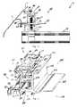
- FIG. 16is a side view of the skirt coupled to the mounting bracket of FIG. 15 .
- FIG. 19is an exploded view of the mounting bracket of FIG. 17 with the skirt brackets removed.
- FIG. 25is a front view of the mounting bracket of FIG. 23 .
- FIG. 29is a detailed view of the mounting bracket, the skirt bracket, and the skirt of FIG. 28 .
- phraseology and terminology used herein with reference to device or element orientationare only used to simplify description of embodiments of the present invention and do not alone indicate or imply that the device or element referred to must have a particular orientation.
- terms such as “first” and “second”are used herein for purposes of description and are not intended to indicate or imply relative importance or significance.
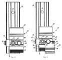
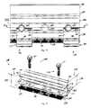
- the mounting bracket 16may include contacts that protrude from the clamp flanges 86 , 90 toward the corresponding support flange 69 , 70 .
- the contactsmay protrude from the support flange 69 , 70 toward the corresponding clamp flange 86 , 90 .
- the contactsprovide direct engagement between the mounting bracket 16 and the solar panels 14 enabling electrical current to flow therebetween.
Landscapes
- Engineering & Computer Science (AREA)
- General Engineering & Computer Science (AREA)
- Mechanical Engineering (AREA)
- Sustainable Development (AREA)
- Sustainable Energy (AREA)
- Thermal Sciences (AREA)
- Chemical & Material Sciences (AREA)
- Combustion & Propulsion (AREA)
- Physics & Mathematics (AREA)
- Life Sciences & Earth Sciences (AREA)
- Architecture (AREA)
- Civil Engineering (AREA)
- Structural Engineering (AREA)
- Roof Covering Using Slabs Or Stiff Sheets (AREA)
Abstract
Description
Claims (26)
Priority Applications (10)
| Application Number | Priority Date | Filing Date | Title |
|---|---|---|---|
| US14/928,235US9431953B2 (en) | 2014-10-31 | 2015-10-30 | Height adjustment bracket for roof applications |
| US15/236,175US10014818B2 (en) | 2014-10-31 | 2016-08-12 | Height adjustment bracket for roof applications |
| US15/286,000US10097132B2 (en) | 2014-04-07 | 2016-10-05 | Height adjustment bracket for roof applications |
| US16/022,691US10644643B2 (en) | 2014-04-07 | 2018-06-29 | Height adjustment bracket for roof applications |
| US16/836,636US10897223B2 (en) | 2014-04-07 | 2020-03-31 | Height adjustment bracket for roof applications |
| US17/122,817US11374531B2 (en) | 2014-04-07 | 2020-12-15 | Height adjustment bracket for roof applications |
| US17/166,572US11863117B2 (en) | 2014-04-07 | 2021-02-03 | Height adjustment bracket for roof applications |
| US17/403,490US11522490B2 (en) | 2014-04-07 | 2021-08-16 | Height adjustment bracket for roof applications |
| US18/060,365US12107530B2 (en) | 2014-04-07 | 2022-11-30 | Height adjustment bracket for roof applications |
| US18/544,870US20240120874A1 (en) | 2014-04-07 | 2023-12-19 | Height adjustment bracket for roof applications |
Applications Claiming Priority (8)
| Application Number | Priority Date | Filing Date | Title |
|---|---|---|---|
| US201462073867P | 2014-10-31 | 2014-10-31 | |
| US201562106406P | 2015-01-22 | 2015-01-22 | |
| US201562106282P | 2015-01-22 | 2015-01-22 | |
| US201562106410P | 2015-01-22 | 2015-01-22 | |
| US201562131480P | 2015-03-11 | 2015-03-11 | |
| US201562134205P | 2015-03-17 | 2015-03-17 | |
| US201562238517P | 2015-10-07 | 2015-10-07 | |
| US14/928,235US9431953B2 (en) | 2014-10-31 | 2015-10-30 | Height adjustment bracket for roof applications |
Related Parent Applications (3)
| Application Number | Title | Priority Date | Filing Date |
|---|---|---|---|
| US14/680,226ContinuationUS9985575B2 (en) | 2014-04-07 | 2015-04-07 | Height adjustment bracket for roof applications |
| US15/990,752Continuation-In-PartUS10476425B2 (en) | 2014-04-07 | 2018-05-28 | Height adjustment bracket for roof applications |
| US16/022,691ContinuationUS10644643B2 (en) | 2014-04-07 | 2018-06-29 | Height adjustment bracket for roof applications |
Related Child Applications (2)
| Application Number | Title | Priority Date | Filing Date |
|---|---|---|---|
| US15/236,175ContinuationUS10014818B2 (en) | 2014-04-07 | 2016-08-12 | Height adjustment bracket for roof applications |
| US15/286,000ContinuationUS10097132B2 (en) | 2014-04-07 | 2016-10-05 | Height adjustment bracket for roof applications |
Publications (2)
| Publication Number | Publication Date |
|---|---|
| US20160126884A1 US20160126884A1 (en) | 2016-05-05 |
| US9431953B2true US9431953B2 (en) | 2016-08-30 |
Family
ID=55853776
Family Applications (8)
| Application Number | Title | Priority Date | Filing Date |
|---|---|---|---|
| US14/928,235Active - ReinstatedUS9431953B2 (en) | 2014-04-07 | 2015-10-30 | Height adjustment bracket for roof applications |
| US15/236,175ActiveUS10014818B2 (en) | 2014-04-07 | 2016-08-12 | Height adjustment bracket for roof applications |
| US15/286,000ActiveUS10097132B2 (en) | 2014-04-07 | 2016-10-05 | Height adjustment bracket for roof applications |
| US16/022,691ActiveUS10644643B2 (en) | 2014-04-07 | 2018-06-29 | Height adjustment bracket for roof applications |
| US16/836,636ActiveUS10897223B2 (en) | 2014-04-07 | 2020-03-31 | Height adjustment bracket for roof applications |
| US17/122,817ActiveUS11374531B2 (en) | 2014-04-07 | 2020-12-15 | Height adjustment bracket for roof applications |
| US17/166,572ActiveUS11863117B2 (en) | 2014-04-07 | 2021-02-03 | Height adjustment bracket for roof applications |
| US17/403,490ActiveUS11522490B2 (en) | 2014-04-07 | 2021-08-16 | Height adjustment bracket for roof applications |
Family Applications After (7)
| Application Number | Title | Priority Date | Filing Date |
|---|---|---|---|
| US15/236,175ActiveUS10014818B2 (en) | 2014-04-07 | 2016-08-12 | Height adjustment bracket for roof applications |
| US15/286,000ActiveUS10097132B2 (en) | 2014-04-07 | 2016-10-05 | Height adjustment bracket for roof applications |
| US16/022,691ActiveUS10644643B2 (en) | 2014-04-07 | 2018-06-29 | Height adjustment bracket for roof applications |
| US16/836,636ActiveUS10897223B2 (en) | 2014-04-07 | 2020-03-31 | Height adjustment bracket for roof applications |
| US17/122,817ActiveUS11374531B2 (en) | 2014-04-07 | 2020-12-15 | Height adjustment bracket for roof applications |
| US17/166,572ActiveUS11863117B2 (en) | 2014-04-07 | 2021-02-03 | Height adjustment bracket for roof applications |
| US17/403,490ActiveUS11522490B2 (en) | 2014-04-07 | 2021-08-16 | Height adjustment bracket for roof applications |
Country Status (1)
| Country | Link |
|---|---|
| US (8) | US9431953B2 (en) |
Cited By (49)
| Publication number | Priority date | Publication date | Assignee | Title |
|---|---|---|---|---|
| US20160251845A1 (en)* | 2013-10-11 | 2016-09-01 | Shaun EVANS | Bracket assembly and method |
| US20160268959A1 (en)* | 2014-11-19 | 2016-09-15 | Ironridge, Inc. | Rail-Less Solar Panel Assembly and Installation Method |
| US20160301356A1 (en)* | 2001-07-20 | 2016-10-13 | Unirac, Inc. | System for mounting a photovoltaic module to a surface |
| US20160308487A1 (en)* | 2015-04-17 | 2016-10-20 | Solarcity Corporation | Photovoltaic mounting system |
| US20170051505A1 (en)* | 2015-04-24 | 2017-02-23 | Worthington Armstrong Venture | Channel for interior glass panel |
| US20170155355A1 (en)* | 2015-11-30 | 2017-06-01 | Solarcity Corporation | Interlock system for mounting and joining photovoltaic modules |
| US20170366131A1 (en)* | 2016-06-21 | 2017-12-21 | Rillito River Solar, Llc | Solar panel mounting system, method and apparatus |
| US9850661B2 (en)* | 2015-09-14 | 2017-12-26 | Pmc Industries, Inc. | Retention apparatus, system and method |
| USD815308S1 (en) | 2016-11-15 | 2018-04-10 | Unirac Inc. | Trimrail extrusion |
| US20180119425A1 (en)* | 2015-09-14 | 2018-05-03 | Pmc Industries, Inc. | Retention apparatus, system and method |
| US9985574B2 (en)* | 2013-02-11 | 2018-05-29 | Jonathan Port | Modular strap mount for solar panels |
| USD824047S1 (en) | 2016-10-13 | 2018-07-24 | Unirac Inc. | Floating splice extrusion |
| USD827157S1 (en) | 2016-10-13 | 2018-08-28 | Unirac Inc. | Base extrusion |
| US10088201B2 (en)* | 2015-10-09 | 2018-10-02 | Pegasus Solar Inc. | Support assemblies for solar energy panels |
| CN109098363A (en)* | 2018-07-26 | 2018-12-28 | 浙江广辉建设有限公司 | A kind of flanging flashing structure and construction method for roofing |
| US20190006983A1 (en)* | 2012-10-12 | 2019-01-03 | Smash Solar, Inc. | Sensing, Interlocking Solar Panel System and Installation Method |
| US20190036474A1 (en)* | 2017-07-25 | 2019-01-31 | Unirac Inc. | Click-On Tower and L-Foot Mount for Attaching Solar Panels to a Roof |
| US10199983B2 (en)* | 2014-11-19 | 2019-02-05 | Ironridge, Inc. | Roof attachment assembly for solar panels and installation method |
| US20190049151A1 (en)* | 2017-08-08 | 2019-02-14 | Unirac Inc. | Universal End Clamp for Mounting Solar Panels on Structural Rails |
| US10211773B2 (en) | 2017-05-24 | 2019-02-19 | Sunmodo Corporation | Height-adjustable solar panel mounting device |
| US10270385B2 (en)* | 2015-08-03 | 2019-04-23 | Jason Sen Xie | Connecting solar modules |
| US20190131918A1 (en)* | 2017-11-01 | 2019-05-02 | Yanegijutsukenkyujo Co., Ltd. | Panel member securing structure and panel member securing tool |
| US20190158012A1 (en)* | 2016-07-05 | 2019-05-23 | Solar Frontier K.K. | Securing Fixture for Photovoltaic Cell Module |
| US10340838B2 (en) | 2015-08-03 | 2019-07-02 | Unirac Inc. | Hybrid solar panel mounting assembly with a tilted ledge |
| US10385573B2 (en) | 2018-01-23 | 2019-08-20 | Jeffrey Van Leuven | Snow brake anchoring system |
| US10461682B2 (en) | 2015-08-03 | 2019-10-29 | Unirac Inc. | Height adjustable solar panel mounting assembly |
| US10511251B2 (en)* | 2017-12-18 | 2019-12-17 | Yanegijutsukenkyujo Co., Ltd. | Solar cell panel securing structure and securing unit |
| US10541641B2 (en) | 2017-10-30 | 2020-01-21 | Solar Slate Solutions | Solar panel mount systems and methods |
| US10594250B2 (en) | 2015-08-03 | 2020-03-17 | Unirac Inc. | Hybrid solar panel mounting assembly |
| US10601360B2 (en) | 2017-09-08 | 2020-03-24 | Unirac Inc. | Replacement tile mount for mounting solar panels on tile roofs |
| US10601361B2 (en) | 2017-10-30 | 2020-03-24 | Solar Slate Solutions | Solar panel mount with compression spacer systems and methods |
| US10797634B1 (en) | 2019-11-27 | 2020-10-06 | Sunmodo Corporation | Height-adjustable rail-less solar panel mounting device for roofs |
| US10819271B2 (en) | 2015-08-03 | 2020-10-27 | Unirac Inc. | Height adjustable solar panel mounting assembly with an asymmetric lower bracket |
| US11018620B2 (en)* | 2018-09-24 | 2021-05-25 | Sunpower Corporation | Solar module skirt assembly |
| US11114577B2 (en)* | 2016-09-30 | 2021-09-07 | Panasonic Intellectual Property Management Co., Ltd. | Photovoltaic power generation device |
| US11365904B2 (en)* | 2017-06-26 | 2022-06-21 | Unirac Inc. | Multi-level mounting system |
| USRE49185E1 (en) | 2013-03-06 | 2022-08-23 | Vermont Slate & Copper Services, Inc. | Snow fence for solar panel |
| US11451187B2 (en)* | 2018-01-19 | 2022-09-20 | Aaron Eriksson | Systems and methods for solar panel mounting |
| US11522489B2 (en) | 2019-04-01 | 2022-12-06 | Unirac Inc. | Bonding clamp as photovoltaic module mounting equipment |
| USD973015S1 (en)* | 2019-04-01 | 2022-12-20 | Unirac Inc. | Bonding clamp |
| US11664761B2 (en)* | 2014-04-07 | 2023-05-30 | EcoFasten Solar, LLC | Solar panel coupling stabilization system |
| US11757399B2 (en) | 2016-08-23 | 2023-09-12 | Pegasus Solar, Inc. | Solar mounting assemblies |
| US20240027103A1 (en)* | 2017-10-09 | 2024-01-25 | Rmh Tech Llc | Rail assembly with invertible side-mount adapter for direct and indirect mounting applications |
| US12203496B2 (en) | 2020-07-09 | 2025-01-21 | Rmh Tech Llc | Mounting system, device, and method |
| US12209407B1 (en)* | 2021-01-20 | 2025-01-28 | Gordon Sales, Inc. | Narrow gap filling structure |
| US12231081B2 (en) | 2018-03-21 | 2025-02-18 | Rmh Tech Llc | PV module mounting assembly with clamp/standoff arrangement |
| US12320375B2 (en) | 2018-12-14 | 2025-06-03 | Rmh Tech Llc | Mounting device for nail strip panels |
| US12348176B2 (en) | 2018-01-19 | 2025-07-01 | Aaron Eriksson | Systems and methods for solar panel mounting |
| US12442181B1 (en) | 2024-06-25 | 2025-10-14 | Gordon Sales, Inc. | Telescoping wall gap filler assembly |
Families Citing this family (45)
| Publication number | Priority date | Publication date | Assignee | Title |
|---|---|---|---|---|
| US9611652B2 (en) | 2011-02-25 | 2017-04-04 | Dustin M. M. Haddock | Mounting device for building surfaces having elongated mounting slot |
| WO2013101597A1 (en) | 2011-12-29 | 2013-07-04 | Haddock Dustin M M | Mounting device for nail strip panels |
| US10186791B2 (en) | 2012-07-05 | 2019-01-22 | Ironridge, Inc. | Assembly for clamping and grounding objects |
| US9825581B2 (en)* | 2013-11-14 | 2017-11-21 | Ecolibrium Solar, Inc. | Modular sloped roof solar mounting system |
| US12301159B2 (en) | 2014-11-13 | 2025-05-13 | Unirac Inc. | Modular sloped roof solar mounting system |
| US11575343B2 (en)* | 2013-12-13 | 2023-02-07 | Quick Mount PV | Waterproofing mounting system for attaching solar modules to a roof |
| US9531319B2 (en)* | 2013-12-23 | 2016-12-27 | Sunpower Corporation | Clamps for solar systems |
| US11368005B2 (en) | 2014-11-19 | 2022-06-21 | Ironridge, Inc. | Wire management structure for a rail-less solar panel assembly |
| US10756668B2 (en)* | 2015-03-11 | 2020-08-25 | Ecouni, Llc | Universal sloped roof solar panel mounting system |
| JP6957357B2 (en)* | 2016-01-19 | 2021-11-02 | ソーラーフロンティア株式会社 | Solar cell module fixture |
| USD849519S1 (en)* | 2016-05-02 | 2019-05-28 | Rinnai America Corporation | Bracket |
| US10443896B2 (en) | 2016-07-29 | 2019-10-15 | Rmh Tech Llc | Trapezoidal rib mounting bracket with flexible legs |
| US10640980B2 (en) | 2016-10-31 | 2020-05-05 | Rmh Tech Llc | Metal panel electrical bonding clip |
| CN106452305B (en)* | 2016-11-16 | 2018-11-23 | 海宁创源太阳能科技有限公司 | A kind of solar energy cell plate mounting bracket and its installation method |
| EP3642953A4 (en) | 2017-06-20 | 2021-03-24 | Watershed Solar, LLC | MOUNTING SYSTEM FOR INTEGRATED PHOTOVOLTAIC MODULES |
| WO2019006357A2 (en)* | 2017-06-29 | 2019-01-03 | Tessolar Incorporated | Photovoltaic module mounting system and method |
| SG10201706990XA (en) | 2017-08-25 | 2019-03-28 | Th3X Construction Consultancy Pte Ltd | Mounting structure |
| US10469022B2 (en)* | 2018-03-04 | 2019-11-05 | Pmc Industries, Inc. | Photo-voltaic panel retention apparatus, system and method |
| WO2019178384A1 (en)* | 2018-03-15 | 2019-09-19 | Better Natural, LLC | Method of integrating solar panels in the roof substrate structure |
| JP6850010B2 (en)* | 2018-05-30 | 2021-03-31 | 株式会社屋根技術研究所 | Panel member fixing structure and panel member fixing tool |
| US11283396B2 (en)* | 2018-11-27 | 2022-03-22 | SolarOff Systems, LLC | Solar panel mounting system and method |
| US10951157B1 (en) | 2019-02-19 | 2021-03-16 | Jonathan W. Young | Panel mounting device with adjustable height mechanism |
| US12119779B2 (en)* | 2019-05-31 | 2024-10-15 | Sunpower Corporation | Photovoltaic module mounting assembly |
| US11181211B1 (en)* | 2019-06-25 | 2021-11-23 | Robert Elliott Morgan | Truss, joist and strut channel mounted support system |
| US11811358B2 (en)* | 2020-02-11 | 2023-11-07 | Apa Solar, Llc | Solar module mounting system |
| WO2021188444A1 (en) | 2020-03-16 | 2021-09-23 | Rmh Tech Llc | Mounting device for a metal roof |
| US11041310B1 (en) | 2020-03-17 | 2021-06-22 | Rmh Tech Llc | Mounting device for controlling uplift of a metal roof |
| EE05879B1 (en)* | 2020-05-15 | 2025-02-17 | Solarstone Oü | System and method for connecting and attaching framed solar panels to roofing to form a weatherproof, building-integrated modular surface |
| US11949369B2 (en)* | 2020-08-20 | 2024-04-02 | Unirac Inc. | Clamp apparatuses and components thereof for mounting solar panel modules |
| US12051993B2 (en)* | 2020-12-18 | 2024-07-30 | Unirac Inc. | Clamping system for mounting a solar panel |
| CN216277630U (en)* | 2021-02-19 | 2022-04-12 | 深圳市路特佳成网络科技有限公司 | Auxiliary mounting device for telescopic safety door fence of baby |
| CA3229531A1 (en) | 2021-08-24 | 2023-03-02 | Ironridge, Inc. | Rail-based solar panel mounting system |
| US11742793B2 (en)* | 2021-10-15 | 2023-08-29 | David G. Garza | Clamp assembly |
| US12114653B2 (en)* | 2021-11-15 | 2024-10-15 | Solaredge Technologies Ltd. | Pest-control structure for photovoltaic installations |
| USD1055316S1 (en)* | 2022-03-16 | 2024-12-24 | BluBase B.V. | Mounting rail |
| USD1075493S1 (en) | 2022-07-06 | 2025-05-20 | Rmh Tech Llc | Clamp for a photovoltaic module mounting assembly |
| US12088237B2 (en)* | 2022-07-11 | 2024-09-10 | E-Soltech, LLC | Trestle |
| US12339040B2 (en)* | 2022-11-23 | 2025-06-24 | Sunmodo Corporation | Rail-less solar panel devices and system for roofs and the like and methods for mounting same |
| US11757400B1 (en)* | 2023-03-15 | 2023-09-12 | Sunmodo Corporation | Devices for mounting solar PV panels to roofs and other mounting structures |
| CN117429589B (en)* | 2023-11-22 | 2024-07-02 | 华中科技大学 | A discrete multi-purpose mounting base |
| PL131978U1 (en)* | 2024-02-16 | 2025-08-18 | Energy 5 Spółka Z Ograniczoną Odpowiedzialnością | End clamp assembly for mounting photovoltaic panels |
| US12149200B1 (en) | 2024-07-03 | 2024-11-19 | Sunmodo Corporation | Railless mounting system and devices for attaching solar modules to roofs |
| US12231076B1 (en) | 2024-09-04 | 2025-02-18 | Sunmodo Corporation | Rail-less mounting system and devices for attaching solar modules to roofs |
| US12286994B1 (en) | 2024-09-09 | 2025-04-29 | Sunmodo Corporation | Railless mounting devices for securing solar modules to roofs |
| CN118889968B (en)* | 2024-09-30 | 2025-04-15 | 同景新能源科技(江山)有限公司 | A high-strength and lightweight mountain photovoltaic bracket |
Citations (150)
| Publication number | Priority date | Publication date | Assignee | Title |
|---|---|---|---|---|
| US4321745A (en) | 1980-04-28 | 1982-03-30 | Energy Design Corp. | Sealing method |
| US4558544A (en) | 1983-03-30 | 1985-12-17 | H. H. Robertson Company | Adjustable pedestal for elevated floors |
| US4744187A (en) | 1987-01-27 | 1988-05-17 | The Firestone Tire & Rubber Company | Mechanical roof fastener |
| US4796403A (en) | 1987-08-28 | 1989-01-10 | Metal Building Components Incorporated | Articulating roofing panel clip |
| US5094056A (en) | 1989-12-01 | 1992-03-10 | Peters William H | Roofing attachment plate |
| US5274978A (en)* | 1991-09-11 | 1994-01-04 | Siemens Solar Gmbh | Clamp for fastening plate-form bodies to a flat support plate |
| US5333423A (en) | 1992-12-23 | 1994-08-02 | Propst Robert L | Floor system |
| US5479745A (en) | 1993-04-21 | 1996-01-02 | Sumitomo Rubber Industries, Ltd. | Floor panel support leg and double floor |
| US5501754A (en) | 1991-09-11 | 1996-03-26 | Taisei Electronic Industries Co., Ltd. | Method of assembling raised dry-floor |
| JPH08296311A (en) | 1995-04-25 | 1996-11-12 | Sanyo Electric Co Ltd | Solar cell module roof installation tool and solar cell module roof installation method |
| US5595366A (en) | 1995-02-06 | 1997-01-21 | Central Piers, Inc. | Seismic foundation pier |
| JP2642606B2 (en) | 1995-01-19 | 1997-08-20 | 有限会社ナカワキ | Fixtures for rooftop equipment |
| JP3041279U (en) | 1997-03-10 | 1997-09-09 | 日本原子力研究所 | Simulated test piece for radiation damage measurement |
| US5791096A (en) | 1997-03-07 | 1998-08-11 | Chen; Kingbow | Raised floor supporting structure |
| US5862635A (en) | 1997-09-16 | 1999-01-26 | Magnum Foundation Systems | Support system for a building structure |
| JP2931240B2 (en) | 1995-11-10 | 1999-08-09 | 株式会社横河ブリッジ | Building with solar cell module |
| JP2972761B1 (en) | 1998-10-26 | 1999-11-08 | 株式会社ヤネハル | Fixing device for roof installation panel on slate roof, method of mounting the same, and installation method of roof installation panel |
| US6024330A (en) | 1998-05-27 | 2000-02-15 | International Business Machines Corporation | Uni-axial floor anchor and leveler for racks |
| JP2000345664A (en) | 1999-06-08 | 2000-12-12 | Kanegafuchi Chem Ind Co Ltd | Exterior heat insulating structure for roof floor |
| US6360491B1 (en) | 2000-01-14 | 2002-03-26 | Stanley A. Ullman | Roof support system for a solar panel |
| US6442906B1 (en) | 2001-08-01 | 2002-09-03 | Hsin Tsai Hwang | Elevation-adjustable rod member locking structure |
| US6453623B1 (en) | 2000-01-24 | 2002-09-24 | Roofers - Annex Inc. | Roof snow barrier |
| US6536729B1 (en) | 1999-05-17 | 2003-03-25 | Robert M. M. Haddock | Bracket assembly including a reservoir |
| US20030070368A1 (en)* | 2001-10-12 | 2003-04-17 | Jefferson Shingleton | Solar module mounting method and clip |
| JP2004060358A (en) | 2002-07-31 | 2004-02-26 | Kyocera Corp | Roof fixing device and solar energy utilization structure using the same |
| US6772564B2 (en) | 2001-07-11 | 2004-08-10 | Richard Joseph Leon | Unitized, pre-fabricated raised access floor arrangement, installation and leveling method, and automatized leveling tool |
| US20040163338A1 (en) | 2003-02-26 | 2004-08-26 | Unirac, Inc., A New Mexico Corporation | Low profile mounting system |
| US20060010786A1 (en) | 2004-07-13 | 2006-01-19 | Rogers Craig C | Roof snow stop |
| US7001098B2 (en) | 2003-06-20 | 2006-02-21 | Taiwan Semiconductor Manufacturing Co., Ltd. | Lock structure and method for using thereof |
| US20060053706A1 (en) | 2002-04-11 | 2006-03-16 | Rwe Schott Solar Inc. | Apparatus for mounting photovoltaic power generating systems on buildings |
| US20060086382A1 (en)* | 2004-02-13 | 2006-04-27 | Plaisted Joshua R | Mechanism for mounting solar modules |
| DE10062697B4 (en) | 2000-12-15 | 2006-06-08 | Rbs Genius Gmbh | Method for installing solar energy modules on non-stabilized subsurface and solar energy system |
| DE102005002828A1 (en) | 2005-01-20 | 2006-08-03 | Magass, Walter | Photovoltaic module assembling substructure for e.g. corrugated fiberboard, has roof plate arranged on profile guide rail, and height adjustable support rod fastened to stand pipe and fixed with winding screw nut |
| US20060260670A1 (en) | 2005-05-19 | 2006-11-23 | Sharp Kabushiki Kaisha | Structure fixing apparatus including support device |
| US7174677B1 (en) | 2003-09-17 | 2007-02-13 | Amerimax Home Products, Inc. | Snow guard for shingled roofs |
| DE102005039495A1 (en) | 2005-08-18 | 2007-03-15 | Hermann Gutmann Werke Ag | Metal profile unit for mounting system for photo voltaic unit, has receiving channel linked with units outer side over passage that is smaller than channel in cross section, and screw channel linked at front surface of receiving channel |
| DE102005059487A1 (en) | 2005-12-08 | 2007-07-05 | Würth Elektronik GmbH & Co. KG | Holding system for roof mounting has mounting plate for insertion in place of roof tile, through openings for attachment arrangements with connection element(s) fed through respective through opening for fixing to substructure element |
| DE102006022870A1 (en) | 2006-02-16 | 2007-09-06 | Thomas Schweiger | Fastening device for fastening objects e.g. for fastening structures e.g. photovoltaic systems, has installation body attached to fastening object and fastening element is fixed with projection section and base section |
| US20070245636A1 (en) | 2006-04-25 | 2007-10-25 | Ayer Sydney L | Snow guard for roofs |
| DE102007026819A1 (en) | 2006-06-06 | 2007-12-20 | Leichtmetallbau Schletter Gmbh | Device for fixing solar energy unit on roof has hanger bolt with upper metric thread for nut which presses an upper sealing element aainst contact pressure element which presses lower sealing element against flat metal roofing |
| WO2007093421A3 (en) | 2006-02-16 | 2007-12-21 | Thomas Schweiger | Fastening device for fastening objects on sealed outer building surfaces and associated installation unit |
| US20080053008A1 (en) | 2006-09-01 | 2008-03-06 | Sharp Kabushiki Kaisha | Structure support apparatus and structure installation method |
| US20080121273A1 (en) | 2006-11-29 | 2008-05-29 | Joshua Reed Plaisted | Mounting assembly for arrays and other surface-mounted equipment |
| JP2008127866A (en) | 2006-11-21 | 2008-06-05 | Aaki Yamade Kk | Panel support |
| US20080250614A1 (en)* | 2007-04-11 | 2008-10-16 | Zante Anthony A | Flexible clamp |
| US20090194098A1 (en)* | 2008-01-31 | 2009-08-06 | Bp Corporation North America Inc. | Solar Module with a Frame for Mounting a Solar Panel |
| DE102008000293A1 (en) | 2008-02-13 | 2009-08-20 | Hilti Aktiengesellschaft | Fastening device for the attachment of plate-shaped elements |
| DE102008012717A1 (en) | 2008-03-05 | 2009-09-10 | Wilhelm Flender Gmbh & Co. Kg | Support device e.g. supporting stand, for fixing of impact points on flat roofs, of building, has support unit with support segments adjusted relative to each other, and base plate and geometry part arranged at respective segments |
| US7592537B1 (en) | 2004-02-05 | 2009-09-22 | John Raymond West | Method and apparatus for mounting photovoltaic modules |
| US20090282755A1 (en) | 2008-05-19 | 2009-11-19 | Powermount Systems, Inc. | Photovoltaic mounting system with locking connectors, adjustable rail height and hinge lock |
| US20090309388A1 (en) | 2008-06-12 | 2009-12-17 | Terrie Ellison | Mounting arrangement for mounting cladding to vehicle body |
| US20100192505A1 (en) | 2009-02-05 | 2010-08-05 | D Three Enterprises, Llc | Interlocking Shape For Use in Construction Members |
| US20100236155A1 (en) | 2009-03-21 | 2010-09-23 | Carlo John Lanza | Protective covering for roof mounted systems |
| JP2010209515A (en) | 2009-03-06 | 2010-09-24 | Sanko Metal Ind Co Ltd | Solar power generation equipment |
| JP2010242367A (en) | 2009-04-06 | 2010-10-28 | Nemii Kk | Solar panel mounting structure |
| US20100307074A1 (en)* | 2010-03-19 | 2010-12-09 | Brian Cecil Stearns | Roofing system and method |
| US20110001030A1 (en)* | 2009-07-01 | 2011-01-06 | Greenonetec Solarindustrie Gmbh | Installation bracket |
| US20110000544A1 (en) | 2009-07-02 | 2011-01-06 | West John R | Drop-in connection apparatus, system, and method for photovoltaic arrays |
| JP2011006864A (en) | 2009-06-24 | 2011-01-13 | Nemii Kk | Structure for attaching solar cell panel |
| JP2011106188A (en) | 2009-11-18 | 2011-06-02 | Sankyo Tateyama Aluminium Inc | Roof |
| US20110154750A1 (en)* | 2008-02-02 | 2011-06-30 | Christian Welter | Fastening system for a plate-shaped structural element |
| US20110179727A1 (en) | 2011-04-01 | 2011-07-28 | Jun Liu | Solar panel and equipment mounting apparatus for roofs |
| US20110214365A1 (en) | 2010-03-08 | 2011-09-08 | JAC-Rack, Inc. | Apparatus and method for securing solar panel cells to a support frame |
| US20110239546A1 (en) | 2010-04-01 | 2011-10-06 | Yanegijutsukenkyujo Co., Ltd. | Installation structure of solar cell module |
| US20110260027A1 (en) | 2010-04-23 | 2011-10-27 | Daetwyler-Clean Energy LLC | Solar panel mounting assembly with locking cap |
| US20110277402A1 (en) | 2009-01-27 | 2011-11-17 | Mounting Systems Gmbh | Solar panel mount |
| US20110302859A1 (en) | 2010-06-14 | 2011-12-15 | Institut De Recherche Fondamentale En Technologies Solaires - IRFTS | Structure for rigidly connecting solar panels to a fixture |
| US20110302857A1 (en) | 2010-06-10 | 2011-12-15 | Energy Design Co. | Building Integrated Solar Array Support Structure Device, System, and Method |
| US20120017526A1 (en)* | 2010-07-23 | 2012-01-26 | Kristian Eide | Solar panel racking system |
| US20120023843A1 (en) | 2010-01-25 | 2012-02-02 | Brian Cecil Stearns | Roofing grommet forming a seal between a roof-mounted structure and a roof |
| US8109048B2 (en) | 2008-02-11 | 2012-02-07 | Zap Solar, Inc. | Apparatus for forming and mounting a photovoltaic array |
| US8122648B1 (en) | 2010-02-02 | 2012-02-28 | Jun Liu | Roof mounting system |
| US20120073219A1 (en)* | 2011-04-05 | 2012-03-29 | Michael Zuritis | Solar array support structure, mounting rail and method of installation thereof |
| US20120073220A1 (en) | 2009-05-11 | 2012-03-29 | Yanegijutsukenkyujo Co., Ltd. | Securing configuration of solar cell module |
| US20120079781A1 (en) | 2010-10-05 | 2012-04-05 | Alexander Koller | Support arrangement |
| US8166720B2 (en) | 2008-01-09 | 2012-05-01 | Talan Products | Roofing membrane retainer |
| US20120102853A1 (en) | 2010-10-05 | 2012-05-03 | Nathan Rizzo | Mount for pitched roof and method of use |
| US20120125410A1 (en) | 2009-07-02 | 2012-05-24 | Zep Soar, Inc. | Method and Apparatus for Forming and Mounting a Photovoltaic Array |
| US20120138764A1 (en)* | 2010-12-03 | 2012-06-07 | Hilti Aktiengesellschaft | Clamp for a plate element, especially for a photovoltaic module |
| US20120144760A1 (en) | 2009-02-05 | 2012-06-14 | D Three Enterprises, Llc | Roof mount sealing assembly |
| US20120152326A1 (en) | 2010-12-13 | 2012-06-21 | John Raymond West | Discrete Attachment Point Apparatus and System for Photovoltaic Arrays |
| US20120192926A1 (en)* | 2010-07-20 | 2012-08-02 | Tatsuji Kambara | Solar array |
| US20120233958A1 (en) | 2011-03-15 | 2012-09-20 | Brian Cecil Stearns | Roof mount assembly |
| US20120234378A1 (en) | 2010-07-02 | 2012-09-20 | John Raymond West | Pivot-Fit Connection Apparatus and System for Photovoltaic Arrays |
| US20120240484A1 (en) | 2009-12-02 | 2012-09-27 | Bygg- Och Miljoteknik Granab Ab | Bar system |
| US20120301661A1 (en) | 2010-12-09 | 2012-11-29 | John Raymond West | Skirt for Photovoltaic Arrays |
| US20120298817A1 (en) | 2009-07-02 | 2012-11-29 | John Raymond West | Pivot-Fit Frame, System and Method for Photovoltaic Arrays |
| US20120298188A1 (en) | 2009-10-06 | 2012-11-29 | Zep Solar, Inc. | Method and Apparatus for Forming and Mounting a Photovoltaic Array |
| US8328149B2 (en) | 2010-02-25 | 2012-12-11 | Stable Tables, Llc | Top access leveler assembly |
| US20130008102A1 (en) | 2010-02-16 | 2013-01-10 | Soprema (Societe Par Actions Simplifiee Unipersonnelle) | Device for fixing plates or panels to a cover, and resulting composite cover |
| US20130009025A1 (en) | 2011-07-08 | 2013-01-10 | Brian Cecil Stearns | Roof mount having built-in failure |
| WO2013043816A1 (en) | 2011-09-23 | 2013-03-28 | Vermont Slate & Copper Services, Inc. | Roof mount assembly and method of mounting same |
| US20130091786A1 (en) | 2011-10-14 | 2013-04-18 | A. Raymond Et Cie | Photovoltaic panel fastening system |
| US20130104471A1 (en) | 2011-11-01 | 2013-05-02 | Yanegijutsukenkyujo Co., Ltd. | Solar cell module securing structure |
| US20130125492A1 (en)* | 2010-07-26 | 2013-05-23 | Efraim Molek | Locking mechanism for panels |
| US20130140416A1 (en) | 2011-06-07 | 2013-06-06 | Zep Solar, Inc. | Apparatus for Forming and Mounting a Photovoltaic Array |
| US20130192150A1 (en) | 2012-01-27 | 2013-08-01 | A. Raymond Et Cie | Solar panel securing system |
| US8505864B1 (en) | 2012-02-29 | 2013-08-13 | Imp Inc. | PV kit for roof assembly |
| US20130284239A1 (en)* | 2012-04-25 | 2013-10-31 | Lg Electronics Inc. | Solar cell module and apparatus for generating photovoltaic power |
| US8584406B2 (en) | 2009-05-20 | 2013-11-19 | Sunpower Corporation | Hole-thru-laminate mounting supports for photovoltaic modules |
| US20130333310A1 (en) | 2012-06-15 | 2013-12-19 | Mas S.R.L. | Modular Structure, Modular Panel To Make Said Modular Structure And Corresponding Method To Make Said Modular Structure |
| US20130333305A1 (en) | 2012-05-29 | 2013-12-19 | Vermont State & Copper Services, Inc. | Snow fence for a solar panel |
| US20130340811A1 (en)* | 2012-06-25 | 2013-12-26 | Sunpower Corporation | Brace for solar module array |
| US8627617B2 (en) | 2010-03-03 | 2014-01-14 | Robert M. M. Haddock | Photovoltaic module mounting assembly |
| US20140026946A1 (en) | 2011-12-13 | 2014-01-30 | Zep Solar, Inc. | Discrete Attachment Point Apparatus and System for Photovoltaic Arrays |
| US20140041321A1 (en) | 2008-11-17 | 2014-02-13 | Alain Poivet | Building Systems |
| US20140042286A1 (en)* | 2012-08-08 | 2014-02-13 | Thomas & Betts International, Inc. | Universal panel clamp |
| US20140053891A1 (en) | 2009-10-06 | 2014-02-27 | Zep Solar, Inc. | Method and Apparatus for Forming and Mounting a Photovoltaic Array |
| US8683761B2 (en) | 2012-06-25 | 2014-04-01 | Sunpower Corporation | Mounting system for solar module array |
| US20140102997A1 (en) | 2012-01-17 | 2014-04-17 | Zep Solar, Inc. | Photovoltaic Module Frame |
| US20140109496A1 (en) | 2012-10-18 | 2014-04-24 | Kevin Stapleton | Panel mounting bracket for standing seam roof and related methods |
| US20140130847A1 (en) | 2012-02-22 | 2014-05-15 | Zep Solar, Inc. | PV Array Mounting for Trapezoidal Metal and Low-Slope Roofs |
| US20140137489A1 (en) | 2011-06-03 | 2014-05-22 | Habdank Pv-Montagesysteme Gmbh & Co. Kg | Fastening system for fastening solar modules |
| US20140158184A1 (en) | 2011-12-09 | 2014-06-12 | Zep Solar, Inc. | Skirt and Other Devices for Photovoltaic Arrays |
| US8756881B2 (en) | 2011-11-09 | 2014-06-24 | Zep Solar, Llc | Solar panel attachment system |
| US20140175244A1 (en) | 2011-12-13 | 2014-06-26 | Zep Solar, Inc. | Connecting Components for Photovoltaic Arrays |
| US20140174511A1 (en) | 2012-12-20 | 2014-06-26 | Zep Solar, Inc. | Photovoltaic Array Mounting Apparatus, Systems, and Methods |
| US20140182662A1 (en) | 2012-06-07 | 2014-07-03 | Zep Solar, Inc. | Method and Apparatus for Forming and Mounting a Photovoltaic Array |
| US8806813B2 (en) | 2006-08-31 | 2014-08-19 | Pvt Solar, Inc. | Technique for electrically bonding solar modules and mounting assemblies |
| US20140246549A1 (en) | 2013-02-26 | 2014-09-04 | Zep Solar, Inc. | Torque Tube Mounted Photovoltaic Apparatus, System, and Method |
| US20140252288A1 (en) | 2013-03-06 | 2014-09-11 | Vermont Slate & Copper Services, Inc. | Snow fence for a solar panel |
| US8833714B2 (en) | 2011-02-25 | 2014-09-16 | Robert M. M. Haddock | Trapezoidal rib mounting bracket |
| US20140299179A1 (en) | 2012-12-20 | 2014-10-09 | Zep Solar Llc | Photovoltaic Array Mounting Apparatus, Systems, and Methods |
| US8857113B2 (en) | 2012-09-28 | 2014-10-14 | Hong Fu Jin Precision Industry (Shenzhen) Co., Ltd. | Locking apparatus |
| US20140305046A1 (en)* | 2010-01-25 | 2014-10-16 | Vermont Slate & Copper Services, Inc. | Roof mount assembly |
| US8875455B1 (en) | 2014-05-28 | 2014-11-04 | Zep Solar, Llc | Ramp mounting system for a flat roof solar array |
| US20140326838A1 (en) | 2013-02-28 | 2014-11-06 | Zep Solar, Inc. | Apparatus, System, and Method for Photovoltaic-Related Wire Management |
| US20140331572A1 (en) | 2013-03-15 | 2014-11-13 | Edward James Singelyn, JR. | Modular system with solar roof |
| US20140339179A1 (en) | 2009-10-06 | 2014-11-20 | Zep Solar Llc | Photovoltaic module frame |
| US20140353435A1 (en)* | 2013-05-31 | 2014-12-04 | Sunmodo Corporation | Direct Rooftop Mounting Apparatus for Solar Panels |
| US20140360558A1 (en) | 2013-06-07 | 2014-12-11 | Zep Solar Llc | Pivot Framing System For Dual Glass Photovoltaic Modules |
| US8925263B2 (en) | 2012-08-13 | 2015-01-06 | Dustin M. M. Haddock | Photovoltaic module mounting assembly |
| US8938932B1 (en) | 2013-12-13 | 2015-01-27 | Quality Product Llc | Rail-less roof mounting system |
| US8946540B1 (en) | 2014-04-18 | 2015-02-03 | Zep Solar, Llc | Imitation solar module for use in a staggered or irregularly shaped solar array |
| US20150040967A1 (en) | 2009-07-02 | 2015-02-12 | Zep Solar Llc | Pivot-fit frame, system and method for photovoltaic modules |
| WO2015020817A1 (en) | 2013-08-06 | 2015-02-12 | Zep Solar Llc | Foothold system on sloped roof |
| US20150040965A1 (en) | 2013-08-12 | 2015-02-12 | Zep Solar Llc | Ground Mount Structure With Mounting Assemblies And Central Quick-Mount Rail |
| US20150075100A1 (en) | 2013-09-13 | 2015-03-19 | Zep Solar Llc | Flashing System For Mounting Photovoltaic Arrays Onto Tile Roofs |
| US20150075589A1 (en) | 2013-09-18 | 2015-03-19 | Zep Solar Llc | Low-Slope Mounted Photovoltaic Array |
| US9010040B2 (en) | 2009-06-26 | 2015-04-21 | Mas Srl | Modular panel for making covering structures for walls, covering structures or walls and method |
| US9010041B2 (en) | 2012-06-25 | 2015-04-21 | Sunpower Corporation | Leveler for solar module array |
| US20150107168A1 (en) | 2012-07-23 | 2015-04-23 | Yanegijutsukenkyujo Co., Ltd. | Securing structure for solar cell module |
| US20150129517A1 (en)* | 2013-11-14 | 2015-05-14 | Ecolibrium Solar, Inc. | Modular Sloped Roof Solar Mounting System |
| US9080792B2 (en) | 2013-07-31 | 2015-07-14 | Ironridge, Inc. | Method and apparatus for mounting solar panels |
| US20150204372A1 (en) | 2014-01-22 | 2015-07-23 | Solarcity Corporation | Method and Apparatus for Limiting Travel and Constraining Liner Movement of a Nut Element Within a Channel |
| US20150218822A1 (en) | 2012-09-03 | 2015-08-06 | Wade Blazley | Composite solar roof |
| US9121545B2 (en) | 2009-09-14 | 2015-09-01 | Bwdt, Llc | System for mounting objects to polymeric membranes |
| US20150249423A1 (en) | 2014-02-28 | 2015-09-03 | Sunpower Corporation | End clamps for solar systems |
| US20150280639A1 (en) | 2011-11-09 | 2015-10-01 | Solarcity Corporation | Self-locking photovoltaic module mounting system |
| US20150288320A1 (en)* | 2014-04-07 | 2015-10-08 | Vermont Slate & Copper Services, Inc. | Height adjustment bracket for roof applications |
Family Cites Families (3)
| Publication number | Priority date | Publication date | Assignee | Title |
|---|---|---|---|---|
| JP3041279B2 (en) | 1998-10-26 | 2000-05-15 | 株式会社ヤネハル | Fixing device for roof installation panel, mounting method thereof, and installation method of roof installation panel |
| JP4041805B2 (en) | 2004-01-30 | 2008-02-06 | 元旦ビューティ工業株式会社 | Exterior structure using roof panels |
| US8752338B2 (en) | 2012-05-04 | 2014-06-17 | D Three Enterprises, Llc | Adjustable roof mounting system |
- 2015
- 2015-10-30USUS14/928,235patent/US9431953B2/enactiveActive - Reinstated
- 2016
- 2016-08-12USUS15/236,175patent/US10014818B2/enactiveActive
- 2016-10-05USUS15/286,000patent/US10097132B2/enactiveActive
- 2018
- 2018-06-29USUS16/022,691patent/US10644643B2/enactiveActive
- 2020
- 2020-03-31USUS16/836,636patent/US10897223B2/enactiveActive
- 2020-12-15USUS17/122,817patent/US11374531B2/enactiveActive
- 2021
- 2021-02-03USUS17/166,572patent/US11863117B2/enactiveActive
- 2021-08-16USUS17/403,490patent/US11522490B2/enactiveActive
Patent Citations (219)
| Publication number | Priority date | Publication date | Assignee | Title |
|---|---|---|---|---|
| US4321745A (en) | 1980-04-28 | 1982-03-30 | Energy Design Corp. | Sealing method |
| US4558544A (en) | 1983-03-30 | 1985-12-17 | H. H. Robertson Company | Adjustable pedestal for elevated floors |
| US4744187A (en) | 1987-01-27 | 1988-05-17 | The Firestone Tire & Rubber Company | Mechanical roof fastener |
| US4796403A (en) | 1987-08-28 | 1989-01-10 | Metal Building Components Incorporated | Articulating roofing panel clip |
| US5094056A (en) | 1989-12-01 | 1992-03-10 | Peters William H | Roofing attachment plate |
| US5501754A (en) | 1991-09-11 | 1996-03-26 | Taisei Electronic Industries Co., Ltd. | Method of assembling raised dry-floor |
| US5274978A (en)* | 1991-09-11 | 1994-01-04 | Siemens Solar Gmbh | Clamp for fastening plate-form bodies to a flat support plate |
| US5333423A (en) | 1992-12-23 | 1994-08-02 | Propst Robert L | Floor system |
| US5479745A (en) | 1993-04-21 | 1996-01-02 | Sumitomo Rubber Industries, Ltd. | Floor panel support leg and double floor |
| JP2642606B2 (en) | 1995-01-19 | 1997-08-20 | 有限会社ナカワキ | Fixtures for rooftop equipment |
| US5595366A (en) | 1995-02-06 | 1997-01-21 | Central Piers, Inc. | Seismic foundation pier |
| JPH08296311A (en) | 1995-04-25 | 1996-11-12 | Sanyo Electric Co Ltd | Solar cell module roof installation tool and solar cell module roof installation method |
| JP2931240B2 (en) | 1995-11-10 | 1999-08-09 | 株式会社横河ブリッジ | Building with solar cell module |
| US5791096A (en) | 1997-03-07 | 1998-08-11 | Chen; Kingbow | Raised floor supporting structure |
| JP3041279U (en) | 1997-03-10 | 1997-09-09 | 日本原子力研究所 | Simulated test piece for radiation damage measurement |
| US5862635A (en) | 1997-09-16 | 1999-01-26 | Magnum Foundation Systems | Support system for a building structure |
| US6024330A (en) | 1998-05-27 | 2000-02-15 | International Business Machines Corporation | Uni-axial floor anchor and leveler for racks |
| JP2972761B1 (en) | 1998-10-26 | 1999-11-08 | 株式会社ヤネハル | Fixing device for roof installation panel on slate roof, method of mounting the same, and installation method of roof installation panel |
| US6536729B1 (en) | 1999-05-17 | 2003-03-25 | Robert M. M. Haddock | Bracket assembly including a reservoir |
| JP2000345664A (en) | 1999-06-08 | 2000-12-12 | Kanegafuchi Chem Ind Co Ltd | Exterior heat insulating structure for roof floor |
| US6360491B1 (en) | 2000-01-14 | 2002-03-26 | Stanley A. Ullman | Roof support system for a solar panel |
| US20020046506A1 (en) | 2000-01-14 | 2002-04-25 | Ullman Stanley A. | Roof support system for a solar panel |
| US6453623B1 (en) | 2000-01-24 | 2002-09-24 | Roofers - Annex Inc. | Roof snow barrier |
| DE10062697B4 (en) | 2000-12-15 | 2006-06-08 | Rbs Genius Gmbh | Method for installing solar energy modules on non-stabilized subsurface and solar energy system |
| US6772564B2 (en) | 2001-07-11 | 2004-08-10 | Richard Joseph Leon | Unitized, pre-fabricated raised access floor arrangement, installation and leveling method, and automatized leveling tool |
| US6442906B1 (en) | 2001-08-01 | 2002-09-03 | Hsin Tsai Hwang | Elevation-adjustable rod member locking structure |
| US20030070368A1 (en)* | 2001-10-12 | 2003-04-17 | Jefferson Shingleton | Solar module mounting method and clip |
| US6672018B2 (en) | 2001-10-12 | 2004-01-06 | Jefferson Shingleton | Solar module mounting method and clip |
| US20060053706A1 (en) | 2002-04-11 | 2006-03-16 | Rwe Schott Solar Inc. | Apparatus for mounting photovoltaic power generating systems on buildings |
| JP2004060358A (en) | 2002-07-31 | 2004-02-26 | Kyocera Corp | Roof fixing device and solar energy utilization structure using the same |
| US20040163338A1 (en) | 2003-02-26 | 2004-08-26 | Unirac, Inc., A New Mexico Corporation | Low profile mounting system |
| US7600349B2 (en) | 2003-02-26 | 2009-10-13 | Unirac, Inc. | Low profile mounting system |
| US7001098B2 (en) | 2003-06-20 | 2006-02-21 | Taiwan Semiconductor Manufacturing Co., Ltd. | Lock structure and method for using thereof |
| US7174677B1 (en) | 2003-09-17 | 2007-02-13 | Amerimax Home Products, Inc. | Snow guard for shingled roofs |
| US7592537B1 (en) | 2004-02-05 | 2009-09-22 | John Raymond West | Method and apparatus for mounting photovoltaic modules |
| US20060086382A1 (en)* | 2004-02-13 | 2006-04-27 | Plaisted Joshua R | Mechanism for mounting solar modules |
| US20060010786A1 (en) | 2004-07-13 | 2006-01-19 | Rogers Craig C | Roof snow stop |
| DE102005002828A1 (en) | 2005-01-20 | 2006-08-03 | Magass, Walter | Photovoltaic module assembling substructure for e.g. corrugated fiberboard, has roof plate arranged on profile guide rail, and height adjustable support rod fastened to stand pipe and fixed with winding screw nut |
| US20060260670A1 (en) | 2005-05-19 | 2006-11-23 | Sharp Kabushiki Kaisha | Structure fixing apparatus including support device |
| DE102005039495A1 (en) | 2005-08-18 | 2007-03-15 | Hermann Gutmann Werke Ag | Metal profile unit for mounting system for photo voltaic unit, has receiving channel linked with units outer side over passage that is smaller than channel in cross section, and screw channel linked at front surface of receiving channel |
| DE102005059487A1 (en) | 2005-12-08 | 2007-07-05 | Würth Elektronik GmbH & Co. KG | Holding system for roof mounting has mounting plate for insertion in place of roof tile, through openings for attachment arrangements with connection element(s) fed through respective through opening for fixing to substructure element |
| WO2007093421A3 (en) | 2006-02-16 | 2007-12-21 | Thomas Schweiger | Fastening device for fastening objects on sealed outer building surfaces and associated installation unit |
| DE102006022870A1 (en) | 2006-02-16 | 2007-09-06 | Thomas Schweiger | Fastening device for fastening objects e.g. for fastening structures e.g. photovoltaic systems, has installation body attached to fastening object and fastening element is fixed with projection section and base section |
| US20070245636A1 (en) | 2006-04-25 | 2007-10-25 | Ayer Sydney L | Snow guard for roofs |
| DE102007026819A1 (en) | 2006-06-06 | 2007-12-20 | Leichtmetallbau Schletter Gmbh | Device for fixing solar energy unit on roof has hanger bolt with upper metric thread for nut which presses an upper sealing element aainst contact pressure element which presses lower sealing element against flat metal roofing |
| US8806813B2 (en) | 2006-08-31 | 2014-08-19 | Pvt Solar, Inc. | Technique for electrically bonding solar modules and mounting assemblies |
| US20080053008A1 (en) | 2006-09-01 | 2008-03-06 | Sharp Kabushiki Kaisha | Structure support apparatus and structure installation method |
| JP2008127866A (en) | 2006-11-21 | 2008-06-05 | Aaki Yamade Kk | Panel support |
| US7857269B2 (en) | 2006-11-29 | 2010-12-28 | Pvt Solar, Inc. | Mounting assembly for arrays and other surface-mounted equipment |
| US20080121273A1 (en) | 2006-11-29 | 2008-05-29 | Joshua Reed Plaisted | Mounting assembly for arrays and other surface-mounted equipment |
| US8177180B2 (en) | 2006-11-29 | 2012-05-15 | Pvt Solar, Inc. | Mounting assembly for arrays and other surface-mounted equipment |
| US20110000526A1 (en) | 2007-04-06 | 2011-01-06 | West John R | Pivot-fit frame, system and method for photovoltaic modules |
| US20080250614A1 (en)* | 2007-04-11 | 2008-10-16 | Zante Anthony A | Flexible clamp |
| US8166720B2 (en) | 2008-01-09 | 2012-05-01 | Talan Products | Roofing membrane retainer |
| US20090194098A1 (en)* | 2008-01-31 | 2009-08-06 | Bp Corporation North America Inc. | Solar Module with a Frame for Mounting a Solar Panel |
| US20110154750A1 (en)* | 2008-02-02 | 2011-06-30 | Christian Welter | Fastening system for a plate-shaped structural element |
| US8109048B2 (en) | 2008-02-11 | 2012-02-07 | Zap Solar, Inc. | Apparatus for forming and mounting a photovoltaic array |
| DE102008000293A1 (en) | 2008-02-13 | 2009-08-20 | Hilti Aktiengesellschaft | Fastening device for the attachment of plate-shaped elements |
| DE102008012717A1 (en) | 2008-03-05 | 2009-09-10 | Wilhelm Flender Gmbh & Co. Kg | Support device e.g. supporting stand, for fixing of impact points on flat roofs, of building, has support unit with support segments adjusted relative to each other, and base plate and geometry part arranged at respective segments |
| US20140251431A1 (en) | 2008-04-08 | 2014-09-11 | Zep Solar, Llc | Method and Apparatus for Forming and Mounting a Photovoltaic Array |
| US20090282755A1 (en) | 2008-05-19 | 2009-11-19 | Powermount Systems, Inc. | Photovoltaic mounting system with locking connectors, adjustable rail height and hinge lock |
| US20090309388A1 (en) | 2008-06-12 | 2009-12-17 | Terrie Ellison | Mounting arrangement for mounting cladding to vehicle body |
| US20140041321A1 (en) | 2008-11-17 | 2014-02-13 | Alain Poivet | Building Systems |
| US20110277402A1 (en) | 2009-01-27 | 2011-11-17 | Mounting Systems Gmbh | Solar panel mount |
| US20120144760A1 (en) | 2009-02-05 | 2012-06-14 | D Three Enterprises, Llc | Roof mount sealing assembly |
| US20100192505A1 (en) | 2009-02-05 | 2010-08-05 | D Three Enterprises, Llc | Interlocking Shape For Use in Construction Members |
| JP2010209515A (en) | 2009-03-06 | 2010-09-24 | Sanko Metal Ind Co Ltd | Solar power generation equipment |
| US20100236155A1 (en) | 2009-03-21 | 2010-09-23 | Carlo John Lanza | Protective covering for roof mounted systems |
| JP2010242367A (en) | 2009-04-06 | 2010-10-28 | Nemii Kk | Solar panel mounting structure |
| US20120073220A1 (en) | 2009-05-11 | 2012-03-29 | Yanegijutsukenkyujo Co., Ltd. | Securing configuration of solar cell module |
| US8955267B2 (en) | 2009-05-20 | 2015-02-17 | Sunpower Corporation | Hole-thru-laminate mounting supports for photovoltaic modules |
| US8584406B2 (en) | 2009-05-20 | 2013-11-19 | Sunpower Corporation | Hole-thru-laminate mounting supports for photovoltaic modules |
| JP2011006864A (en) | 2009-06-24 | 2011-01-13 | Nemii Kk | Structure for attaching solar cell panel |
| US9010040B2 (en) | 2009-06-26 | 2015-04-21 | Mas Srl | Modular panel for making covering structures for walls, covering structures or walls and method |
| US20110001030A1 (en)* | 2009-07-01 | 2011-01-06 | Greenonetec Solarindustrie Gmbh | Installation bracket |
| US20120298186A1 (en) | 2009-07-02 | 2012-11-29 | Zep Solar, Inc. | Method and Apparatus for Forming and Mounting a Photovoltaic Array |
| US20130180573A1 (en) | 2009-07-02 | 2013-07-18 | Zep Solar, Inc. | Method and Apparatus for Forming and Mounting a Photovoltaic Array |
| US20110000519A1 (en) | 2009-07-02 | 2011-01-06 | West John R | Pivot-fit connection apparatus, system, and method for photovoltaic modules |
| US20130183084A1 (en) | 2009-07-02 | 2013-07-18 | Zep Solar, Inc. | Apparatus for Forming and Mounting a Photovoltaic Array |
| US20130180572A1 (en) | 2009-07-02 | 2013-07-18 | Zep Solar, Inc. | Method and Apparatus for Forming and Mounting a Photovoltaic Array |
| US20130180574A1 (en) | 2009-07-02 | 2013-07-18 | Zep Solar, Inc. | Method and Apparatus for Forming and Mounting a Photovoltaic Array |
| US20150316292A1 (en) | 2009-07-02 | 2015-11-05 | Solarcity Corporation | Pivot-fit frame, system and method for photovoltaic modules |
| US20150013756A1 (en) | 2009-07-02 | 2015-01-15 | Zep Solar Llc | Pivot-fit frame, system and method for photovoltaic modules |
| US8375654B1 (en) | 2009-07-02 | 2013-02-19 | Zap Solar, Inc. | Apparatus for forming and mounting a photovoltaic array |
| US20120255598A1 (en) | 2009-07-02 | 2012-10-11 | Zep Solar, Inc. | Method and Apparatus for Forming and Mounting a Photovoltaic Array |
| US20150040967A1 (en) | 2009-07-02 | 2015-02-12 | Zep Solar Llc | Pivot-fit frame, system and method for photovoltaic modules |
| US20150155820A1 (en) | 2009-07-02 | 2015-06-04 | Solarcity Corporation | Pivot-fit connection apparatus, system, and method for photovoltaic modules |
| US20110000544A1 (en) | 2009-07-02 | 2011-01-06 | West John R | Drop-in connection apparatus, system, and method for photovoltaic arrays |
| US20120298817A1 (en) | 2009-07-02 | 2012-11-29 | John Raymond West | Pivot-Fit Frame, System and Method for Photovoltaic Arrays |
| US20150075590A1 (en) | 2009-07-02 | 2015-03-19 | Zep Solar Llc | Pivot-fit frame, system and method for photovoltaic modules |
| US20120125410A1 (en) | 2009-07-02 | 2012-05-24 | Zep Soar, Inc. | Method and Apparatus for Forming and Mounting a Photovoltaic Array |
| US8991114B2 (en) | 2009-07-02 | 2015-03-31 | Zep Solar, Llc | Pivot-fit connection apparatus, system, and method for photovoltaic modules |
| US20150222222A1 (en) | 2009-07-02 | 2015-08-06 | Solarcity Corporation | Pivot-fit connection apparatus, system, and method for photovoltaic modules |
| US20120279558A1 (en) | 2009-07-02 | 2012-11-08 | Zep Solar, Inc. | Method and Apparatus for Forming and Mounting a Photovoltaic Array |
| US20150222221A1 (en) | 2009-07-02 | 2015-08-06 | Solarcity Corporation | Pivot-fit connection apparatus, system and method for photovoltaic modules |
| US20110000520A1 (en) | 2009-07-02 | 2011-01-06 | West John R | Leveling foot apparatus, system, and method for photovoltaic arrays |
| US20150155821A1 (en) | 2009-07-02 | 2015-06-04 | Solarcity Corporation | Pivot-fit connection apparatus, system, and method for photovoltaic modules |
| US20120260972A1 (en) | 2009-07-02 | 2012-10-18 | Zep Solar, Inc. | Method and Apparatus for Forming and Mounting a Photovoltaic Array |
| US9121545B2 (en) | 2009-09-14 | 2015-09-01 | Bwdt, Llc | System for mounting objects to polymeric membranes |
| US20120298188A1 (en) | 2009-10-06 | 2012-11-29 | Zep Solar, Inc. | Method and Apparatus for Forming and Mounting a Photovoltaic Array |
| US9154074B2 (en) | 2009-10-06 | 2015-10-06 | Solarcity Corporation | Apparatus for forming and mounting a photovoltaic array |
| US20140339179A1 (en) | 2009-10-06 | 2014-11-20 | Zep Solar Llc | Photovoltaic module frame |
| US20150033658A1 (en) | 2009-10-06 | 2015-02-05 | Zep Solar Llc | Apparatus for forming and mounting a photovoltaic array |
| US20140053891A1 (en) | 2009-10-06 | 2014-02-27 | Zep Solar, Inc. | Method and Apparatus for Forming and Mounting a Photovoltaic Array |
| US20150068590A1 (en) | 2009-10-06 | 2015-03-12 | Zep Solar Llc | Apparatus for forming and mounting a photovoltaic array |
| JP2011106188A (en) | 2009-11-18 | 2011-06-02 | Sankyo Tateyama Aluminium Inc | Roof |
| US20120240484A1 (en) | 2009-12-02 | 2012-09-27 | Bygg- Och Miljoteknik Granab Ab | Bar system |
| US8397443B2 (en) | 2009-12-02 | 2013-03-19 | Bygg-Och Miljoteknik Granab Ab | Bar system |
| US8146299B2 (en) | 2010-01-25 | 2012-04-03 | Vermont Slate & Copper Services, Inc. | Roofing grommet forming a seal between a roof-mounted structure and a roof |
| US20120023843A1 (en) | 2010-01-25 | 2012-02-02 | Brian Cecil Stearns | Roofing grommet forming a seal between a roof-mounted structure and a roof |
| US8209914B2 (en) | 2010-01-25 | 2012-07-03 | Vermont Slate & Copper Services, Inc. | Roofing grommet forming a seal between a roof-mounted structure and a roof |
| US8272174B2 (en) | 2010-01-25 | 2012-09-25 | Vermont Slate & Copper Services, Inc. | Roofing grommet forming a seal between a roof-mounted structure and a roof |
| US8245454B2 (en) | 2010-01-25 | 2012-08-21 | Vermont Slate & Copper Services, Inc. | Roofing grommet forming a seal between a roof-mounted structure and a roof |
| US20140305046A1 (en)* | 2010-01-25 | 2014-10-16 | Vermont Slate & Copper Services, Inc. | Roof mount assembly |
| US8122648B1 (en) | 2010-02-02 | 2012-02-28 | Jun Liu | Roof mounting system |
| US8733037B2 (en) | 2010-02-16 | 2014-05-27 | Soprema | Device for fixing plates or panels to a cover, and resulting composite cover |
| US20130008102A1 (en) | 2010-02-16 | 2013-01-10 | Soprema (Societe Par Actions Simplifiee Unipersonnelle) | Device for fixing plates or panels to a cover, and resulting composite cover |
| US8328149B2 (en) | 2010-02-25 | 2012-12-11 | Stable Tables, Llc | Top access leveler assembly |
| US8627617B2 (en) | 2010-03-03 | 2014-01-14 | Robert M. M. Haddock | Photovoltaic module mounting assembly |
| US20110214365A1 (en) | 2010-03-08 | 2011-09-08 | JAC-Rack, Inc. | Apparatus and method for securing solar panel cells to a support frame |
| US8225557B2 (en) | 2010-03-19 | 2012-07-24 | Vermont Slate & Copper Services, Inc. | Roofing system and method |
| US8153700B2 (en) | 2010-03-19 | 2012-04-10 | Vermont Slate & Copper Services, Inc. | Roofing system and method |
| US20100307074A1 (en)* | 2010-03-19 | 2010-12-09 | Brian Cecil Stearns | Roofing system and method |
| US8181398B2 (en) | 2010-03-19 | 2012-05-22 | Vermont Slate & Copper Services, Inc. | Roofing system and method |
| US8413388B2 (en) | 2010-03-19 | 2013-04-09 | Vermont Slate & Copper Services, Inc. | Roofing system and method |
| US8166713B2 (en) | 2010-03-19 | 2012-05-01 | Vermont Slate & Copper Services, Inc. | Roofing system and method |
| US8151522B2 (en) | 2010-03-19 | 2012-04-10 | Vermont Slate & Copper Services, Inc. | Roofing system and method |
| US20110239546A1 (en) | 2010-04-01 | 2011-10-06 | Yanegijutsukenkyujo Co., Ltd. | Installation structure of solar cell module |
| US20110260027A1 (en) | 2010-04-23 | 2011-10-27 | Daetwyler-Clean Energy LLC | Solar panel mounting assembly with locking cap |
| US20110302857A1 (en) | 2010-06-10 | 2011-12-15 | Energy Design Co. | Building Integrated Solar Array Support Structure Device, System, and Method |
| US20110302859A1 (en) | 2010-06-14 | 2011-12-15 | Institut De Recherche Fondamentale En Technologies Solaires - IRFTS | Structure for rigidly connecting solar panels to a fixture |
| US20120234378A1 (en) | 2010-07-02 | 2012-09-20 | John Raymond West | Pivot-Fit Connection Apparatus and System for Photovoltaic Arrays |
| US20120192926A1 (en)* | 2010-07-20 | 2012-08-02 | Tatsuji Kambara | Solar array |
| US20120017526A1 (en)* | 2010-07-23 | 2012-01-26 | Kristian Eide | Solar panel racking system |
| US20130125492A1 (en)* | 2010-07-26 | 2013-05-23 | Efraim Molek | Locking mechanism for panels |
| US20120079781A1 (en) | 2010-10-05 | 2012-04-05 | Alexander Koller | Support arrangement |
| US20120102853A1 (en) | 2010-10-05 | 2012-05-03 | Nathan Rizzo | Mount for pitched roof and method of use |
| US20120138764A1 (en)* | 2010-12-03 | 2012-06-07 | Hilti Aktiengesellschaft | Clamp for a plate element, especially for a photovoltaic module |
| US20120301661A1 (en) | 2010-12-09 | 2012-11-29 | John Raymond West | Skirt for Photovoltaic Arrays |
| US20120152326A1 (en) | 2010-12-13 | 2012-06-21 | John Raymond West | Discrete Attachment Point Apparatus and System for Photovoltaic Arrays |
| US20120266946A1 (en) | 2010-12-13 | 2012-10-25 | John Raymond West | Discrete Attachment Point Apparatus and System for Photovoltaic Arrays |
| US8833714B2 (en) | 2011-02-25 | 2014-09-16 | Robert M. M. Haddock | Trapezoidal rib mounting bracket |
| US20120233958A1 (en) | 2011-03-15 | 2012-09-20 | Brian Cecil Stearns | Roof mount assembly |
| WO2012125327A4 (en) | 2011-03-15 | 2013-02-28 | Vermont Slate & Copper Services, Inc. | Roof mount assembly |
| US20110179727A1 (en) | 2011-04-01 | 2011-07-28 | Jun Liu | Solar panel and equipment mounting apparatus for roofs |
| US20120073219A1 (en)* | 2011-04-05 | 2012-03-29 | Michael Zuritis | Solar array support structure, mounting rail and method of installation thereof |
| US20140137489A1 (en) | 2011-06-03 | 2014-05-22 | Habdank Pv-Montagesysteme Gmbh & Co. Kg | Fastening system for fastening solar modules |
| US20130140416A1 (en) | 2011-06-07 | 2013-06-06 | Zep Solar, Inc. | Apparatus for Forming and Mounting a Photovoltaic Array |
| WO2013009375A1 (en) | 2011-07-08 | 2013-01-17 | Vermont Slate & Copper Services, Inc. | Roof mount having built-in failure |
| US20130009025A1 (en) | 2011-07-08 | 2013-01-10 | Brian Cecil Stearns | Roof mount having built-in failure |
| US20130074441A1 (en) | 2011-09-23 | 2013-03-28 | Vermont Slate & Copper Services, Inc. | Roof mount assembly and method of mounting same |
| WO2013043816A1 (en) | 2011-09-23 | 2013-03-28 | Vermont Slate & Copper Services, Inc. | Roof mount assembly and method of mounting same |
| US20130091786A1 (en) | 2011-10-14 | 2013-04-18 | A. Raymond Et Cie | Photovoltaic panel fastening system |
| US20130104471A1 (en) | 2011-11-01 | 2013-05-02 | Yanegijutsukenkyujo Co., Ltd. | Solar cell module securing structure |
| US8756881B2 (en) | 2011-11-09 | 2014-06-24 | Zep Solar, Llc | Solar panel attachment system |
| US20150280639A1 (en) | 2011-11-09 | 2015-10-01 | Solarcity Corporation | Self-locking photovoltaic module mounting system |
| US20150069198A1 (en) | 2011-11-09 | 2015-03-12 | Zep Solar Llc | Solar panel attachment system |
| US9062897B2 (en) | 2011-11-09 | 2015-06-23 | Zep Solar, Llc | Solar panel attachment system |
| US9097441B2 (en) | 2011-11-09 | 2015-08-04 | Zep Solar, Llc | Solar panel attachment system |
| US20140223838A1 (en) | 2011-11-09 | 2014-08-14 | Zep Solar, Llc | Solar Panel Attachment System |
| US20150200618A9 (en) | 2011-12-09 | 2015-07-16 | Zep Solar, Inc. | Skirt and Other Devices for Photovoltaic Arrays |
| US20140158184A1 (en) | 2011-12-09 | 2014-06-12 | Zep Solar, Inc. | Skirt and Other Devices for Photovoltaic Arrays |
| US20140175244A1 (en) | 2011-12-13 | 2014-06-26 | Zep Solar, Inc. | Connecting Components for Photovoltaic Arrays |
| US9166524B2 (en) | 2011-12-13 | 2015-10-20 | Solarcity Corporation | Connecting components for photovoltaic arrays |
| US20140026946A1 (en) | 2011-12-13 | 2014-01-30 | Zep Solar, Inc. | Discrete Attachment Point Apparatus and System for Photovoltaic Arrays |
| US20150155823A1 (en) | 2011-12-13 | 2015-06-04 | Solarcity Corporation | Connecting components for photovoltaic arrays |
| US20140102997A1 (en) | 2012-01-17 | 2014-04-17 | Zep Solar, Inc. | Photovoltaic Module Frame |
| US20130192150A1 (en) | 2012-01-27 | 2013-08-01 | A. Raymond Et Cie | Solar panel securing system |
| US20140130847A1 (en) | 2012-02-22 | 2014-05-15 | Zep Solar, Inc. | PV Array Mounting for Trapezoidal Metal and Low-Slope Roofs |
| US8505864B1 (en) | 2012-02-29 | 2013-08-13 | Imp Inc. | PV kit for roof assembly |
| US20130284239A1 (en)* | 2012-04-25 | 2013-10-31 | Lg Electronics Inc. | Solar cell module and apparatus for generating photovoltaic power |
| US20130333305A1 (en) | 2012-05-29 | 2013-12-19 | Vermont State & Copper Services, Inc. | Snow fence for a solar panel |
| US20140182662A1 (en) | 2012-06-07 | 2014-07-03 | Zep Solar, Inc. | Method and Apparatus for Forming and Mounting a Photovoltaic Array |
| US20130333310A1 (en) | 2012-06-15 | 2013-12-19 | Mas S.R.L. | Modular Structure, Modular Panel To Make Said Modular Structure And Corresponding Method To Make Said Modular Structure |
| US8683761B2 (en) | 2012-06-25 | 2014-04-01 | Sunpower Corporation | Mounting system for solar module array |
| US8943765B2 (en) | 2012-06-25 | 2015-02-03 | Sunpower Corporation | Brace for solar module array |
| US20150222225A1 (en) | 2012-06-25 | 2015-08-06 | Sunpower Corporation | Leveler for solar module array |
| US20130340811A1 (en)* | 2012-06-25 | 2013-12-26 | Sunpower Corporation | Brace for solar module array |
| US9010041B2 (en) | 2012-06-25 | 2015-04-21 | Sunpower Corporation | Leveler for solar module array |
| US20150107168A1 (en) | 2012-07-23 | 2015-04-23 | Yanegijutsukenkyujo Co., Ltd. | Securing structure for solar cell module |
| US20140042286A1 (en)* | 2012-08-08 | 2014-02-13 | Thomas & Betts International, Inc. | Universal panel clamp |
| US8925263B2 (en) | 2012-08-13 | 2015-01-06 | Dustin M. M. Haddock | Photovoltaic module mounting assembly |
| US20150218822A1 (en) | 2012-09-03 | 2015-08-06 | Wade Blazley | Composite solar roof |
| US8857113B2 (en) | 2012-09-28 | 2014-10-14 | Hong Fu Jin Precision Industry (Shenzhen) Co., Ltd. | Locking apparatus |
| US20140109496A1 (en) | 2012-10-18 | 2014-04-24 | Kevin Stapleton | Panel mounting bracket for standing seam roof and related methods |
| US9231517B2 (en) | 2012-12-20 | 2016-01-05 | Solarcity Corporation | Photovoltaic array mounting apparatus, systems, and methods |
| US20140174511A1 (en) | 2012-12-20 | 2014-06-26 | Zep Solar, Inc. | Photovoltaic Array Mounting Apparatus, Systems, and Methods |
| US9003729B2 (en) | 2012-12-20 | 2015-04-14 | Zep Solar, Llc | Photovoltaic array mounting apparatus, systems, and methods |
| US20140299179A1 (en) | 2012-12-20 | 2014-10-09 | Zep Solar Llc | Photovoltaic Array Mounting Apparatus, Systems, and Methods |
| US20150180405A1 (en) | 2012-12-20 | 2015-06-25 | Solarcity Corporation | Photovoltaic array mounting apparatus, systems, and methods |
| US20140246549A1 (en) | 2013-02-26 | 2014-09-04 | Zep Solar, Inc. | Torque Tube Mounted Photovoltaic Apparatus, System, and Method |
| US20140326838A1 (en) | 2013-02-28 | 2014-11-06 | Zep Solar, Inc. | Apparatus, System, and Method for Photovoltaic-Related Wire Management |
| US20140252288A1 (en) | 2013-03-06 | 2014-09-11 | Vermont Slate & Copper Services, Inc. | Snow fence for a solar panel |
| US20140331572A1 (en) | 2013-03-15 | 2014-11-13 | Edward James Singelyn, JR. | Modular system with solar roof |
| US20140353435A1 (en)* | 2013-05-31 | 2014-12-04 | Sunmodo Corporation | Direct Rooftop Mounting Apparatus for Solar Panels |
| US20140360558A1 (en) | 2013-06-07 | 2014-12-11 | Zep Solar Llc | Pivot Framing System For Dual Glass Photovoltaic Modules |
| US9080792B2 (en) | 2013-07-31 | 2015-07-14 | Ironridge, Inc. | Method and apparatus for mounting solar panels |
| US20150041251A1 (en) | 2013-08-06 | 2015-02-12 | Zep Solar Llc | Foothold System on Sloped Roof |
| WO2015020817A1 (en) | 2013-08-06 | 2015-02-12 | Zep Solar Llc | Foothold system on sloped roof |
| US9109371B2 (en) | 2013-08-06 | 2015-08-18 | Solarcity Corporation | Foothold system on sloped roof |
| WO2015023526A1 (en) | 2013-08-12 | 2015-02-19 | Zep Solar Llc | Ground mount structure with mounting assemblies and central quick-mount rail |
| US20150040965A1 (en) | 2013-08-12 | 2015-02-12 | Zep Solar Llc | Ground Mount Structure With Mounting Assemblies And Central Quick-Mount Rail |
| WO2015039007A2 (en) | 2013-09-13 | 2015-03-19 | Zep Solar Llc | Flashing system for mounting photovoltaic arrays onto tile roofs |
| US20150075100A1 (en) | 2013-09-13 | 2015-03-19 | Zep Solar Llc | Flashing System For Mounting Photovoltaic Arrays Onto Tile Roofs |
| US20150075589A1 (en) | 2013-09-18 | 2015-03-19 | Zep Solar Llc | Low-Slope Mounted Photovoltaic Array |
| WO2015042260A1 (en) | 2013-09-18 | 2015-03-26 | Zep Solar Llc | Low slope mounted photovoltaic array |
| US20150129517A1 (en)* | 2013-11-14 | 2015-05-14 | Ecolibrium Solar, Inc. | Modular Sloped Roof Solar Mounting System |
| US20150168021A1 (en) | 2013-12-13 | 2015-06-18 | Quality Product Llc | Rail-less roof mounting clamp assembly |
| US8938932B1 (en) | 2013-12-13 | 2015-01-27 | Quality Product Llc | Rail-less roof mounting system |
| WO2015112461A1 (en) | 2014-01-22 | 2015-07-30 | Solarcity Corporation | Method and apparatus for limiting travel and constraining liner movement of a nut element within a channel |
| US20150204372A1 (en) | 2014-01-22 | 2015-07-23 | Solarcity Corporation | Method and Apparatus for Limiting Travel and Constraining Liner Movement of a Nut Element Within a Channel |
| US20150249423A1 (en) | 2014-02-28 | 2015-09-03 | Sunpower Corporation | End clamps for solar systems |
| US20150288320A1 (en)* | 2014-04-07 | 2015-10-08 | Vermont Slate & Copper Services, Inc. | Height adjustment bracket for roof applications |
| WO2015160644A1 (en) | 2014-04-18 | 2015-10-22 | Zep Solar Llc | An imitation solar module for use in a staggered or irregularly shaped solar array |
| US20150303865A1 (en) | 2014-04-18 | 2015-10-22 | Zep Solar Llc | Imitation Solar Module For Use In A Staggered Or Irregularly Shaped Solar Array |
| US8946540B1 (en) | 2014-04-18 | 2015-02-03 | Zep Solar, Llc | Imitation solar module for use in a staggered or irregularly shaped solar array |
| US8875455B1 (en) | 2014-05-28 | 2014-11-04 | Zep Solar, Llc | Ramp mounting system for a flat roof solar array |
| WO2015183971A1 (en) | 2014-05-28 | 2015-12-03 | Solarcity Corporation | Ramp mounting system for a flat roof solar array |
| US8984819B1 (en) | 2014-05-28 | 2015-03-24 | Zep Solar, Llc | Ramp mounting system for a flat roof solar array |
Cited By (75)
| Publication number | Priority date | Publication date | Assignee | Title |
|---|---|---|---|---|
| US20160301356A1 (en)* | 2001-07-20 | 2016-10-13 | Unirac, Inc. | System for mounting a photovoltaic module to a surface |
| US10536108B2 (en)* | 2012-10-12 | 2020-01-14 | Smash Solar, Inc. | Sensing, interlocking solar panel system and installation method |
| US20190006983A1 (en)* | 2012-10-12 | 2019-01-03 | Smash Solar, Inc. | Sensing, Interlocking Solar Panel System and Installation Method |
| US9985574B2 (en)* | 2013-02-11 | 2018-05-29 | Jonathan Port | Modular strap mount for solar panels |
| USRE49185E1 (en) | 2013-03-06 | 2022-08-23 | Vermont Slate & Copper Services, Inc. | Snow fence for solar panel |
| US9869085B2 (en)* | 2013-10-11 | 2018-01-16 | Shaun EVANS | Bracket assembly and method |
| US20160251845A1 (en)* | 2013-10-11 | 2016-09-01 | Shaun EVANS | Bracket assembly and method |
| US11664761B2 (en)* | 2014-04-07 | 2023-05-30 | EcoFasten Solar, LLC | Solar panel coupling stabilization system |
| US9647433B2 (en)* | 2014-11-19 | 2017-05-09 | Ironridge, Inc. | Rail-less solar panel assembly and installation method |
| US10199983B2 (en)* | 2014-11-19 | 2019-02-05 | Ironridge, Inc. | Roof attachment assembly for solar panels and installation method |
| US20160268959A1 (en)* | 2014-11-19 | 2016-09-15 | Ironridge, Inc. | Rail-Less Solar Panel Assembly and Installation Method |
| US20160308487A1 (en)* | 2015-04-17 | 2016-10-20 | Solarcity Corporation | Photovoltaic mounting system |
| US10020773B2 (en)* | 2015-04-17 | 2018-07-10 | Solarcity Corporation | Photovoltaic mounting system |
| US20170051505A1 (en)* | 2015-04-24 | 2017-02-23 | Worthington Armstrong Venture | Channel for interior glass panel |
| US11942892B2 (en) | 2015-08-03 | 2024-03-26 | Unirac Inc. | Hybrid solar panel mounting assembly |
| US12289079B2 (en) | 2015-08-03 | 2025-04-29 | Unirac, Inc. | Hybrid solar panel mounting assembly |
| US10340838B2 (en) | 2015-08-03 | 2019-07-02 | Unirac Inc. | Hybrid solar panel mounting assembly with a tilted ledge |
| US11489481B2 (en) | 2015-08-03 | 2022-11-01 | Unirac Inc. | Hybrid solar panel mounting assembly |
| US12289078B2 (en) | 2015-08-03 | 2025-04-29 | Unirac, Inc. | Hybrid solar panel mounting assembly |
| US10819271B2 (en) | 2015-08-03 | 2020-10-27 | Unirac Inc. | Height adjustable solar panel mounting assembly with an asymmetric lower bracket |
| US10461682B2 (en) | 2015-08-03 | 2019-10-29 | Unirac Inc. | Height adjustable solar panel mounting assembly |
| US11894800B2 (en) | 2015-08-03 | 2024-02-06 | Unirac Inc. | Height adjustable solar panel mounting assembly |
| US11183965B2 (en) | 2015-08-03 | 2021-11-23 | Unirac Inc. | Height adjustable solar panel mounting assembly |
| US10270385B2 (en)* | 2015-08-03 | 2019-04-23 | Jason Sen Xie | Connecting solar modules |
| US10594250B2 (en) | 2015-08-03 | 2020-03-17 | Unirac Inc. | Hybrid solar panel mounting assembly |
| US9850661B2 (en)* | 2015-09-14 | 2017-12-26 | Pmc Industries, Inc. | Retention apparatus, system and method |
| US20190169851A1 (en)* | 2015-09-14 | 2019-06-06 | Pmc Industries, Inc. | Retention apparatus, system and method |
| US10947734B2 (en)* | 2015-09-14 | 2021-03-16 | Pmc Industries, Inc. | Retention apparatus, system and method |
| US20180119425A1 (en)* | 2015-09-14 | 2018-05-03 | Pmc Industries, Inc. | Retention apparatus, system and method |
| US11041314B2 (en)* | 2015-09-14 | 2021-06-22 | Pmc Industries, Inc. | Retention apparatus, system and method |
| US10845093B2 (en) | 2015-10-09 | 2020-11-24 | Pegasus Solar Inc. | Support assemblies for solar energy panels |
| US10088201B2 (en)* | 2015-10-09 | 2018-10-02 | Pegasus Solar Inc. | Support assemblies for solar energy panels |
| US10340836B2 (en)* | 2015-11-30 | 2019-07-02 | Solarcity Corporation | Interlock system for mounting and joining photovoltaic modules |
| US20170155355A1 (en)* | 2015-11-30 | 2017-06-01 | Solarcity Corporation | Interlock system for mounting and joining photovoltaic modules |
| US20170366131A1 (en)* | 2016-06-21 | 2017-12-21 | Rillito River Solar, Llc | Solar panel mounting system, method and apparatus |
| US20190158012A1 (en)* | 2016-07-05 | 2019-05-23 | Solar Frontier K.K. | Securing Fixture for Photovoltaic Cell Module |
| US10648698B2 (en)* | 2016-07-05 | 2020-05-12 | Solar Frontier K.K. | Securing fixture for photovoltaic cell module |
| US11757399B2 (en) | 2016-08-23 | 2023-09-12 | Pegasus Solar, Inc. | Solar mounting assemblies |
| US11114577B2 (en)* | 2016-09-30 | 2021-09-07 | Panasonic Intellectual Property Management Co., Ltd. | Photovoltaic power generation device |
| USD827157S1 (en) | 2016-10-13 | 2018-08-28 | Unirac Inc. | Base extrusion |
| USD824047S1 (en) | 2016-10-13 | 2018-07-24 | Unirac Inc. | Floating splice extrusion |
| USD815308S1 (en) | 2016-11-15 | 2018-04-10 | Unirac Inc. | Trimrail extrusion |
| US10211773B2 (en) | 2017-05-24 | 2019-02-19 | Sunmodo Corporation | Height-adjustable solar panel mounting device |
| US11774144B2 (en) | 2017-06-26 | 2023-10-03 | Unirac Inc. | Multi-level mounting system |
| US12429251B2 (en) | 2017-06-26 | 2025-09-30 | Unirac, Inc. | Multi-level mounting system |
| US11365904B2 (en)* | 2017-06-26 | 2022-06-21 | Unirac Inc. | Multi-level mounting system |
| US20190036474A1 (en)* | 2017-07-25 | 2019-01-31 | Unirac Inc. | Click-On Tower and L-Foot Mount for Attaching Solar Panels to a Roof |
| US11251743B2 (en)* | 2017-07-25 | 2022-02-15 | Unirac Inc. | Click-on tower and l-foot mount for attaching solar panels to a roof |
| US12301160B2 (en) | 2017-07-25 | 2025-05-13 | Unirac, Inc. | Click-on tower and L-foot mount for attaching solar panels to a roof |
| US10451315B2 (en)* | 2017-08-08 | 2019-10-22 | Unirac Inc. | Universal end clamp for mounting solar panels on structural rails |
| US20190049151A1 (en)* | 2017-08-08 | 2019-02-14 | Unirac Inc. | Universal End Clamp for Mounting Solar Panels on Structural Rails |
| US11274855B2 (en) | 2017-08-08 | 2022-03-15 | Unirac Inc. | Universal end clamp for mounting solar panels on structural rails |
| US10601360B2 (en) | 2017-09-08 | 2020-03-24 | Unirac Inc. | Replacement tile mount for mounting solar panels on tile roofs |
| US11205989B2 (en) | 2017-09-08 | 2021-12-21 | Unirac Inc. | Replacement tile mount for mounting solar panels on tile roofs |
| US20240027103A1 (en)* | 2017-10-09 | 2024-01-25 | Rmh Tech Llc | Rail assembly with invertible side-mount adapter for direct and indirect mounting applications |
| US10541641B2 (en) | 2017-10-30 | 2020-01-21 | Solar Slate Solutions | Solar panel mount systems and methods |
| US10601361B2 (en) | 2017-10-30 | 2020-03-24 | Solar Slate Solutions | Solar panel mount with compression spacer systems and methods |
| US10742160B2 (en)* | 2017-11-01 | 2020-08-11 | Yanegijutsukenkyujo Co., Ltd. | Panel member securing structure and panel member securing tool |
| US20190131918A1 (en)* | 2017-11-01 | 2019-05-02 | Yanegijutsukenkyujo Co., Ltd. | Panel member securing structure and panel member securing tool |
| US10511251B2 (en)* | 2017-12-18 | 2019-12-17 | Yanegijutsukenkyujo Co., Ltd. | Solar cell panel securing structure and securing unit |
| US11451187B2 (en)* | 2018-01-19 | 2022-09-20 | Aaron Eriksson | Systems and methods for solar panel mounting |
| US12348176B2 (en) | 2018-01-19 | 2025-07-01 | Aaron Eriksson | Systems and methods for solar panel mounting |
| US10385573B2 (en) | 2018-01-23 | 2019-08-20 | Jeffrey Van Leuven | Snow brake anchoring system |
| US12231081B2 (en) | 2018-03-21 | 2025-02-18 | Rmh Tech Llc | PV module mounting assembly with clamp/standoff arrangement |
| CN109098363A (en)* | 2018-07-26 | 2018-12-28 | 浙江广辉建设有限公司 | A kind of flanging flashing structure and construction method for roofing |
| US12283915B2 (en) | 2018-09-24 | 2025-04-22 | Unirac, Inc. | Solar module skirt assembly |
| US11018620B2 (en)* | 2018-09-24 | 2021-05-25 | Sunpower Corporation | Solar module skirt assembly |
| US11728764B2 (en) | 2018-09-24 | 2023-08-15 | Sunpower Corporation | Solar module skirt assembly |
| US12320375B2 (en) | 2018-12-14 | 2025-06-03 | Rmh Tech Llc | Mounting device for nail strip panels |
| USD973015S1 (en)* | 2019-04-01 | 2022-12-20 | Unirac Inc. | Bonding clamp |
| US11522489B2 (en) | 2019-04-01 | 2022-12-06 | Unirac Inc. | Bonding clamp as photovoltaic module mounting equipment |
| US10797634B1 (en) | 2019-11-27 | 2020-10-06 | Sunmodo Corporation | Height-adjustable rail-less solar panel mounting device for roofs |
| US12203496B2 (en) | 2020-07-09 | 2025-01-21 | Rmh Tech Llc | Mounting system, device, and method |
| US12209407B1 (en)* | 2021-01-20 | 2025-01-28 | Gordon Sales, Inc. | Narrow gap filling structure |
| US12442181B1 (en) | 2024-06-25 | 2025-10-14 | Gordon Sales, Inc. | Telescoping wall gap filler assembly |
Also Published As
| Publication number | Publication date |
|---|---|
| US20180316301A1 (en) | 2018-11-01 |
| US10644643B2 (en) | 2020-05-05 |
| US20210376781A1 (en) | 2021-12-02 |
| US11374531B2 (en) | 2022-06-28 |
| US10097132B2 (en) | 2018-10-09 |
| US20210167720A1 (en) | 2021-06-03 |
| US10897223B2 (en) | 2021-01-19 |
| US20160352283A1 (en) | 2016-12-01 |
| US10014818B2 (en) | 2018-07-03 |
| US11522490B2 (en) | 2022-12-06 |
| US20170025987A1 (en) | 2017-01-26 |
| US20210104973A1 (en) | 2021-04-08 |
| US20160126884A1 (en) | 2016-05-05 |
| US20200252023A1 (en) | 2020-08-06 |
| US11863117B2 (en) | 2024-01-02 |
Similar Documents
| Publication | Publication Date | Title |
|---|---|---|
| US10644643B2 (en) | Height adjustment bracket for roof applications | |
| US10476425B2 (en) | Height adjustment bracket for roof applications | |
| US12107530B2 (en) | Height adjustment bracket for roof applications | |
| USRE49185E1 (en) | Snow fence for solar panel | |
| US11616468B2 (en) | PV module mounting assembly with clamp/standoff arrangement | |
| US12179710B2 (en) | Roof attachment for rail-based solar racking system | |
| US11444438B2 (en) | Switch cabinet frame structure having closed base frame | |
| US9107548B2 (en) | Toilet seat hinge assembly | |
| US20050236542A1 (en) | Appliance mounting device | |
| US9923511B2 (en) | Connecting solar modules | |
| US20090180842A1 (en) | Panel fastener | |
| US20130320161A1 (en) | Support foot for applying and distributing forces to a pressure-sensitive substrate as well as a stand system having such a support foot | |
| US9392869B2 (en) | Clamp for surface-mounted devices | |
| CN106133460A (en) | Mounting assembly for solar panel system and method of using same | |
| US20090272572A1 (en) | Mounting plate and cover assembly for electrical devices | |
| JP2022531665A (en) | Variable geometry installation bracket for DIN rails | |
| US20240120874A1 (en) | Height adjustment bracket for roof applications | |
| US20220255494A1 (en) | Modular Sloped Roof Solar Mounting System | |
| US20050161955A1 (en) | Systems and methods for holding together first and second objects and fasteners for use with the systems and methods | |
| JPH04113668U (en) | Hinge and electrical equipment boxes | |
| JP2016079796A (en) | Mounting structure for mounting member and external member | |
| JPH08333852A (en) | Snow guard fitting |
Legal Events
| Date | Code | Title | Description |
|---|---|---|---|
| AS | Assignment | Owner name:VERMONT SLATE & COPPER SERVICES, INC., VERMONT Free format text:ASSIGNMENT OF ASSIGNORS INTEREST;ASSIGNORS:STEARNS, BRIAN CECIL;BORNEMANN, ALEXANDER GRANT;REEL/FRAME:036925/0046 Effective date:20151030 | |
| ZAAA | Notice of allowance and fees due | Free format text:ORIGINAL CODE: NOA | |
| ZAAB | Notice of allowance mailed | Free format text:ORIGINAL CODE: MN/=. | |
| STCF | Information on status: patent grant | Free format text:PATENTED CASE | |
| AS | Assignment | Owner name:RILLITO RIVER SOLAR, LLC, ARIZONA Free format text:ASSIGNMENT OF ASSIGNORS INTEREST;ASSIGNOR:VERMONT SLATE & COPPER SERVICES, INC.;REEL/FRAME:039844/0026 Effective date:20160801 | |
| AS | Assignment | Owner name:RILLITO RIVER SOLAR, LLC, ARIZONA Free format text:MERGER;ASSIGNOR:RILLITO RIVER SOLAR, LLC;REEL/FRAME:051146/0295 Effective date:20191030 Owner name:ECOFASTEN SOLAR, LLC, ARIZONA Free format text:CHANGE OF NAME;ASSIGNOR:RILLITO RIVER SOLAR, LLC;REEL/FRAME:051146/0854 Effective date:20181220 | |
| MAFP | Maintenance fee payment | Free format text:PAYMENT OF MAINTENANCE FEE, 4TH YEAR, LARGE ENTITY (ORIGINAL EVENT CODE: M1551); ENTITY STATUS OF PATENT OWNER: LARGE ENTITY Year of fee payment:4 | |
| FEPP | Fee payment procedure | Free format text:ENTITY STATUS SET TO SMALL (ORIGINAL EVENT CODE: SMAL); ENTITY STATUS OF PATENT OWNER: SMALL ENTITY | |
| AS | Assignment | Owner name:WILMINGTON TRUST, NATIONAL ASSOCIATION, DELAWARE Free format text:SECURITY INTEREST;ASSIGNORS:ECOFASTEN SOLAR, LLC;IRONRIDGE, INC.;PANELCLAW, INC.;AND OTHERS;REEL/FRAME:057365/0001 Effective date:20210830 | |
| FEPP | Fee payment procedure | Free format text:ENTITY STATUS SET TO UNDISCOUNTED (ORIGINAL EVENT CODE: BIG.); ENTITY STATUS OF PATENT OWNER: LARGE ENTITY | |
| FEPP | Fee payment procedure | Free format text:MAINTENANCE FEE REMINDER MAILED (ORIGINAL EVENT CODE: REM.); ENTITY STATUS OF PATENT OWNER: LARGE ENTITY | |
| FEPP | Fee payment procedure | Free format text:SURCHARGE, PETITION TO ACCEPT PYMT AFTER EXP, UNINTENTIONAL (ORIGINAL EVENT CODE: M1558); ENTITY STATUS OF PATENT OWNER: LARGE ENTITY Free format text:PETITION RELATED TO MAINTENANCE FEES FILED (ORIGINAL EVENT CODE: PMFP); ENTITY STATUS OF PATENT OWNER: LARGE ENTITY | |
| MAFP | Maintenance fee payment | Free format text:PAYMENT OF MAINTENANCE FEE, 8TH YEAR, LARGE ENTITY (ORIGINAL EVENT CODE: M1552); ENTITY STATUS OF PATENT OWNER: LARGE ENTITY Year of fee payment:8 | |
| LAPS | Lapse for failure to pay maintenance fees | Free format text:PATENT EXPIRED FOR FAILURE TO PAY MAINTENANCE FEES (ORIGINAL EVENT CODE: EXP.); ENTITY STATUS OF PATENT OWNER: LARGE ENTITY | |
| STCH | Information on status: patent discontinuation | Free format text:PATENT EXPIRED DUE TO NONPAYMENT OF MAINTENANCE FEES UNDER 37 CFR 1.362 | |
| PRDP | Patent reinstated due to the acceptance of a late maintenance fee | Effective date:20241031 | |
| FP | Lapsed due to failure to pay maintenance fee | Effective date:20240830 | |
| FEPP | Fee payment procedure | Free format text:PETITION RELATED TO MAINTENANCE FEES GRANTED (ORIGINAL EVENT CODE: PMFG); ENTITY STATUS OF PATENT OWNER: LARGE ENTITY | |
| STCF | Information on status: patent grant | Free format text:PATENTED CASE |