US9431390B2 - Compact electrostatic discharge (ESD) protection structure - Google Patents
Compact electrostatic discharge (ESD) protection structureDownload PDFInfo
- Publication number
- US9431390B2 US9431390B2US14/267,185US201414267185AUS9431390B2US 9431390 B2US9431390 B2US 9431390B2US 201414267185 AUS201414267185 AUS 201414267185AUS 9431390 B2US9431390 B2US 9431390B2
- Authority
- US
- United States
- Prior art keywords
- protection device
- esd protection
- fet
- hemt
- esd
- Prior art date
- Legal status (The legal status is an assumption and is not a legal conclusion. Google has not performed a legal analysis and makes no representation as to the accuracy of the status listed.)
- Active, expires
Links
Images


Classifications
- H01L27/0292—
- H—ELECTRICITY
- H10—SEMICONDUCTOR DEVICES; ELECTRIC SOLID-STATE DEVICES NOT OTHERWISE PROVIDED FOR
- H10D—INORGANIC ELECTRIC SEMICONDUCTOR DEVICES
- H10D89/00—Aspects of integrated devices not covered by groups H10D84/00 - H10D88/00
- H10D89/60—Integrated devices comprising arrangements for electrical or thermal protection, e.g. protection circuits against electrostatic discharge [ESD]
- H10D89/601—Integrated devices comprising arrangements for electrical or thermal protection, e.g. protection circuits against electrostatic discharge [ESD] for devices having insulated gate electrodes, e.g. for IGFETs or IGBTs
- H10D89/921—Integrated devices comprising arrangements for electrical or thermal protection, e.g. protection circuits against electrostatic discharge [ESD] for devices having insulated gate electrodes, e.g. for IGFETs or IGBTs characterised by the configuration of the interconnections connecting the protective arrangements, e.g. ESD buses
- H01L27/0207—
- H01L27/0248—
- H01L27/0605—
- H01L29/778—
- H—ELECTRICITY
- H10—SEMICONDUCTOR DEVICES; ELECTRIC SOLID-STATE DEVICES NOT OTHERWISE PROVIDED FOR
- H10D—INORGANIC ELECTRIC SEMICONDUCTOR DEVICES
- H10D30/00—Field-effect transistors [FET]
- H10D30/40—FETs having zero-dimensional [0D], one-dimensional [1D] or two-dimensional [2D] charge carrier gas channels
- H10D30/47—FETs having zero-dimensional [0D], one-dimensional [1D] or two-dimensional [2D] charge carrier gas channels having 2D charge carrier gas channels, e.g. nanoribbon FETs or high electron mobility transistors [HEMT]
- H—ELECTRICITY
- H10—SEMICONDUCTOR DEVICES; ELECTRIC SOLID-STATE DEVICES NOT OTHERWISE PROVIDED FOR
- H10D—INORGANIC ELECTRIC SEMICONDUCTOR DEVICES
- H10D84/00—Integrated devices formed in or on semiconductor substrates that comprise only semiconducting layers, e.g. on Si wafers or on GaAs-on-Si wafers
- H10D84/01—Manufacture or treatment
- H—ELECTRICITY
- H10—SEMICONDUCTOR DEVICES; ELECTRIC SOLID-STATE DEVICES NOT OTHERWISE PROVIDED FOR
- H10D—INORGANIC ELECTRIC SEMICONDUCTOR DEVICES
- H10D84/00—Integrated devices formed in or on semiconductor substrates that comprise only semiconducting layers, e.g. on Si wafers or on GaAs-on-Si wafers
- H10D84/80—Integrated devices formed in or on semiconductor substrates that comprise only semiconducting layers, e.g. on Si wafers or on GaAs-on-Si wafers characterised by the integration of at least one component covered by groups H10D12/00 or H10D30/00, e.g. integration of IGFETs
- H10D84/811—Combinations of field-effect devices and one or more diodes, capacitors or resistors
- H—ELECTRICITY
- H10—SEMICONDUCTOR DEVICES; ELECTRIC SOLID-STATE DEVICES NOT OTHERWISE PROVIDED FOR
- H10D—INORGANIC ELECTRIC SEMICONDUCTOR DEVICES
- H10D89/00—Aspects of integrated devices not covered by groups H10D84/00 - H10D88/00
- H10D89/10—Integrated device layouts
- H—ELECTRICITY
- H10—SEMICONDUCTOR DEVICES; ELECTRIC SOLID-STATE DEVICES NOT OTHERWISE PROVIDED FOR
- H10D—INORGANIC ELECTRIC SEMICONDUCTOR DEVICES
- H10D89/00—Aspects of integrated devices not covered by groups H10D84/00 - H10D88/00
- H10D89/60—Integrated devices comprising arrangements for electrical or thermal protection, e.g. protection circuits against electrostatic discharge [ESD]
- H01L27/0629—
Definitions
- the present disclosurerelates to a semiconductor protection structures, in particular electrostatic discharge (ESD) protection structures.
- ESDelectrostatic discharge
- a Schottky gate depletion-mode field effect deviceis sensitive to ESD damage due to its delicate metallic gate structure (0.5 ⁇ m or smaller metal gate length). Unlike CMOS silicon or bipolar transistor processes, there is no robust P-N junction diode available in a high-electron-mobility transistor (HEMT) process to form a compact ESD protection diode.
- HEMThigh-electron-mobility transistor
- a HEMTalso known as heterostructure FET (HFET) or modulation-doped FET (MODFET) is a field-effect transistor incorporating a junction between two materials with different band gaps (i.e., a heterojunction) as the channel instead of a doped region (as is generally the case for MOSFET).
- HEMTenhanced HEMT
- pseudomorphic HEMTpHEMT
- mHEMTmetamorphic HEMT
- induced HEMTa large HEMT formed with the gate of the pHEMT device
- These multiple Schottky diodesconsume a large area in an expensive GaAs integrated circuit die.
- a Schottky diodealso known as a hot carrier diode, is a semiconductor diode which has a low forward voltage drop and a very fast switching action. There is a small voltage drop across the diode terminals when current flows through a diode. A normal diode will have a voltage drop between 0.6 to 1.7 volts, while a Schottky diode voltage drop is usually between 0.15 and 0.45 volts. This lower voltage drop provides better system efficiency and higher switching speed. In a Schottky diode, a semiconductor-metal junction is formed between a semiconductor and a metal, thus creating a Schottky barrier.
- An N-type semiconductoracts as the cathode and the metal side acts as the anode of the Schottky diode.
- This Schottky barrierresults in both a low forward voltage drop and very fast switching. ESD protection can be provided by cascading several large Schottky diodes. Due to the Schottky diode's low turn on voltage, several stacked diodes are required to handle the operating voltage, and a large area is required to handle the current. Thus using a Schottky diode configuration requires a large die area.
- an electrostatic discharge (ESD) protection devicemay comprise: a field effect transistor (FET) having a drain, at least two gates and a source, wherein the drain thereof may be coupled to a node of a circuit to be protected from an ESD event; at least one diode coupled between the source of the FET and a power supply common; a first resistor coupled between the at least two gates of the FET; and a second resistor coupled to a one of the at least two gates and the power supply common.
- FETfield effect transistor
- one of the at least two gatesmay be a trigger gate and another one of the at least two gates may be a discharge gate.
- the FETmay be a depletion-mode FET.
- the at least one diodemay be two diodes connected in series between the source of the FET and power supply common.
- the power supply commonmay be coupled to an electrical ground
- the depletion-mode FETmay be a high-electron-mobility transistor (HEMT).
- the HEMTmay be a pseudomorphic HEMT (pHEMT).
- the HEMTmay be a metamorphic HEMT (mHEMT).
- the HEMTmay be an induced HEMT.
- the FET, the at least one diode and the first and second resistorsmay be fabricated on an integrated circuit die and coupled to the circuit node that may be coupled to an external connection of the integrated circuit die.
- a function of the external connection of the integrated circuit diemay be selected from the group consisting of an analog input, a digital input, an analog output, a digital output, an analog input/output, a digital input/output, a power connection, a bias input, and an external compensation capacitor.
- an electrostatic discharge (ESD) protection devicemay comprise: a first field effect transistor (FET) having a drain, at least two gates and a source, wherein the drain thereof may be coupled to a node of a circuit to be protected from an ESD event; at least one first diode having an anode coupled to the source of the first FET; a first resistor coupled between the at least two gates of the first FET; and a second resistor coupled to a one of the at least two gates and a cathode of the at least one first diode; a second field effect transistor (FET) having a drain, at least two gates and a source, wherein the drain thereof may be coupled to a power supply common; at least one second diode having an cathode coupled to the cathode of the at least one first diode; a third resistor coupled between the at least two gates of the second FET; and a fourth resistor coupled to a one of the at least two gates of second FET and a cath
- one of the at least two gates of the first and second FETsmay be trigger gates and another one of the at least two gates of the first and second FETs may be discharge gates.
- the first and second FETsmay be depletion-mode FETs.
- the at least one first and second diodesmay be two diodes each connected in series between the sources of the first and second FETs.
- the power supply commonmay be coupled to an electrical ground.
- the first and second depletion-mode FETsmay be high-electron-mobility transistors (HEMTs).
- the HEMTsmay be selected from the group consisting of pseudomorphic HEMTs (pHEMTs), metamorphic HEMTs (mHEMTs) and induced HEMTs.
- the first and second FETs, the at least one first and second diodes and the first, second, third and fourth resistorsmay be fabricated on an integrated circuit die and coupled to the circuit node that may be coupled to an external connection of the integrated circuit die.
- a function of the external connection of the integrated circuit diemay comprise a radio frequency signal input.
- a function of the external connection of the integrated circuit diemay comprise a radio frequency signal output.
- FIG. 1illustrates a schematic isometric cross section diagram of a HEMT device, according to the teachings of this disclosure
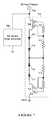
- FIG. 2illustrates a schematic diagram of a prior technology single polarity depletion-mode FET ESD protection device for direct current (DC) and control ports;
- FIG. 3illustrates a schematic diagram of a single polarity multi-gate Schottky depletion-mode FET ESD protection device for direct current (DC) and control ports, according to a specific example embodiment of this disclosure
- FIG. 4illustrates a schematic plan view of a prior technology structure for the ESD protection device shown in FIG. 2 ;
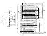
- FIG. 5illustrates a schematic plan view of a structure for the ESD protection device shown in FIG. 3 , according to a specific example embodiment of this disclosure
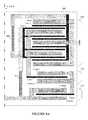
- FIG. 6illustrates a more detailed schematic plan view of a structure for the ESD protection device shown in FIG. 3 , according to a specific example embodiment of this disclosure
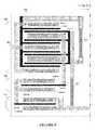
- FIG. 7illustrates a schematic diagram of a dual polarity multi-gate Schottky depletion-mode FET ESD protection device for radio frequency (RF) ports, according to another specific example embodiment of this disclosure.
- FIGS. 8 and 8Aillustrate a schematic plan view of a structure for the ESD protection device shown in FIG. 7 , according to a specific example embodiment of this disclosure.
- a pseudomorphic high electron mobility transistoralso known as heretrostructure FET or modulation-doped FET is used as an example herein to describe the concept of a compact ESD protection device according to various embodiments disclosed herein.
- pHEMTpseudomorphic high electron mobility transistor
- heretrostructure FETmodulation-doped FET
- several large Schottky diodeshad to be formed with the gate of a pHEMT device and cascaded in series to increase the voltage and adequately protect the active circuits.
- These multiple diode devicesconsumed a large area in an expensive GaAs integrated circuit die.
- the multiple-gates of the HEMT devicemay be used to form ESD trigger and charge draining paths for protection of circuits following the ESD protection devices and structures.
- the ESD protection device structurecan be laid out in a much smaller area than the multiple diode ESD device structure. It is contemplated and within the scope of this disclosure that various types of HEMT devices, e.g., pHEMT, mHEMT, induced HEMT, etc., may be used with the ESD protection devices disclosed herein.
- FIG. 1depicted is a schematic isometric cross section diagram of a HEMT device, according to the teachings of this disclosure.
- a pHEMTis shown for illustrative purposes, but it is contemplated and within the scope of this invention that other HEMT devices may be similarly used according to the teachings of this disclosure.
- the HEMT devicemay comprise a substrate 112 , a two dimensional electron gas layer 110 , a spacer 108 , a barrier 106 , a capping layer 104 , and metal drain, source and gate electrodes 102 .
- the source, gate and drain metal 102may comprise, but is not limited to, gold.
- the barrier 106may comprise, but is not limited to, aluminum gallium arsenide (AlGaAs).
- the spacer 108may comprise, but is not limited to, gallium arsenide (GaAs).
- the two dimensional electron gas layer 110may comprise, but is not limited to, indium gallium arsenide (InGaAs).
- the substratemay comprise, but is not limited to, high resistivity GaAs.
- the first resistor 210may have a resistance value of from about 500 ohms to about 2000 ohms.
- the second resistor 212may have a resistance value of about 2000 ohms.
- FIGS. 2 and 4depicted are a schematic diagram of a prior technology single polarity depletion-mode FET ESD protection device for direct current (DC) and control ports, and a schematic plan view of the prior technology structure for the ESD protection device shown in FIG. 2 .
- a single polarity single-gate ESD protection device 202has been used to protect control signal and/or bias supply nodes (pins) of circuits 206 of an integrated circuit package (not shown).
- the ESD protection device 202may comprise a field effect transistor (FET) 208 having a drain (D), a source (S) and a single gate (G); first and second Schottky diodes 214 and 216 , a third diode 218 , and first and second gate resistors 210 and 212 .
- the third diode 218is a trigger diode that conducts (goes into avalanche breakdown) when an ESD event occurs, thereby turning on the transistor 208 .
- the Schottky diodes 214 and 216are used for voltage level shifting to prevent the depletion mode transistor 208 from turning on and conducting current during normal operation.
- FIGS. 3, 5 and 6depicted are a schematic diagram of a single polarity multi-gate Schottky depletion-mode FET ESD protection device for direct current (DC) and control ports, and schematic plan views of a structure for the ESD protection device shown in FIG. 3 , according to a specific example embodiment of this disclosure.
- a single polarity ESD protection device 302 having Schottky multi-gatesmay be used to protect control signal and/or bias supply nodes (pins) of circuits 306 of an integrated circuit package (not shown).
- the ESD protection device 302may comprise a multi-gate Schottky depletion-mode field effect transistor (FET) 308 , e.g., HEMT device, having a drain (D), a source (S), first and second trigger gates (G 1 and G 2 ), first and second diodes 314 and 316 , and first and second gate resistors 310 and 312 . It is contemplated and within the scope of this disclosure that the FET 308 may have two or more gates. At least one level shifting diode may be coupled between the source of the FET 308 and a power supply common, e.g., an electrical ground.
- FETfield effect transistor
- the drain of the FET 308may be coupled to a node 304 that may be coupled to an external connection (pin) of an integrated circuit (IC) package (not shown).
- the external connection (pin) of the IC packagemay be used as, for example but not limited to, an analog input, a digital input, an analog output, a digital output, an analog input/output, a digital input/output, a power connection, a bias input, an external compensation capacitor, etc.
- first and second diodes 314 and 316are coupled between the source of the FET 308 and a power supply common, e.g., ground, and provide voltage level shifting to prevent a depletion mode transistor from turning on (conducting).
- the drain current of the FET 308provides another path to dissipate the positive electrostatic charges at the node 304 and helps to prevent the first trigger gate G 1 from having excessive breakdown current that may damage the first trigger gate G 1 .
- a multi-gate structure FET 308is a unique way to combine a trigger diode device and a discharge gate FET that saves precious integrated circuit die area.
- only three active device areasare necessary for the single polarity multiple-gate ESD protection device 302 : 1) FET 308 , 2) and 3) first and second diodes 314 and 316 .
- the prior technology ESD protection device 202requires four active device areas 1) FET 208 , 2) trigger third diode 218 , 3) and 4) level shifting diodes 214 and 216 . Therefore, the prior technology ESD protection device 202 requires a larger active device area on the integrated circuit die (not shown) than does the single polarity multiple-gate ESD protection device 302 to achieve the same ESD protection level, according to the teachings of this disclosure.
- FIGS. 7, 8 and 8Adepicted are a schematic diagram of a dual polarity multi-gate Schottky depletion-mode FET ESD protection device for radio frequency (RF) ports, and a schematic plan view of a structure for the ESD protection device shown in FIG. 7 , according to another specific example embodiment of this disclosure.
- a dual polarity multi-gate Schottky depletion-mode FET ESD protection device 702may be used to protect control, signal and/or bias supply nodes (pins) of circuits 706 of an integrated circuit package (not shown).
- the ESD protection device 702may comprise a first HEMT device 308 having a drain, a source and first and second gates (G 1 and G 2 ); first and second diodes 314 and 316 , first and second gate resistors 310 and 312 , a second HEMT device 708 having a drain, a source and first and second gates (G 1 and G 2 ); third and fourth diodes 714 and 716 , third and fourth gate resistors 710 and 712 .
- the ESD protection device 702may advantageously be used with RF ports that are associated with high RF power devices. This ESD protection circuit may be used in the presence of large positive and negative RF voltage swings.
- This dual polarity multi-gate FET ESD protection device 702is substantially similar to that of the single polarity multi-gate ESD protection device 308 .
- Elements 708 - 716function as a mirror image of the elements 308 - 316 .
Landscapes
- Semiconductor Integrated Circuits (AREA)
- Junction Field-Effect Transistors (AREA)
- Engineering & Computer Science (AREA)
- General Engineering & Computer Science (AREA)
Abstract
Description
Claims (21)
Priority Applications (8)
| Application Number | Priority Date | Filing Date | Title |
|---|---|---|---|
| US14/267,185US9431390B2 (en) | 2013-05-03 | 2014-05-01 | Compact electrostatic discharge (ESD) protection structure |
| TW103115860ATWI631685B (en) | 2013-05-03 | 2014-05-02 | Compact electrostatic discharge (esd) protection structure |
| KR1020157031623AKR102198021B1 (en) | 2013-05-03 | 2014-05-02 | Compact electrostatic discharge (esd) protection structure |
| EP14728389.9AEP2992555B1 (en) | 2013-05-03 | 2014-05-02 | Compact electrostatic discharge (esd) protection structure |
| PCT/US2014/036499WO2014179651A1 (en) | 2013-05-03 | 2014-05-02 | Compact electrostatic discharge (esd) protection structure |
| CN201480025014.7ACN105190887B (en) | 2013-05-03 | 2014-05-02 | Compact static discharge (ESD) protects structure |
| JP2016512060AJP6366687B2 (en) | 2013-05-03 | 2014-05-02 | Compact electrostatic discharge (ESD) protection structure |
| US15/250,855US9685432B2 (en) | 2013-05-03 | 2016-08-29 | Compact electrostatic discharge (ESD) protection structure |
Applications Claiming Priority (2)
| Application Number | Priority Date | Filing Date | Title |
|---|---|---|---|
| US201361819252P | 2013-05-03 | 2013-05-03 | |
| US14/267,185US9431390B2 (en) | 2013-05-03 | 2014-05-01 | Compact electrostatic discharge (ESD) protection structure |
Related Child Applications (1)
| Application Number | Title | Priority Date | Filing Date |
|---|---|---|---|
| US15/250,855DivisionUS9685432B2 (en) | 2013-05-03 | 2016-08-29 | Compact electrostatic discharge (ESD) protection structure |
Publications (2)
| Publication Number | Publication Date |
|---|---|
| US20140327048A1 US20140327048A1 (en) | 2014-11-06 |
| US9431390B2true US9431390B2 (en) | 2016-08-30 |
Family
ID=51841005
Family Applications (2)
| Application Number | Title | Priority Date | Filing Date |
|---|---|---|---|
| US14/267,185Active2034-06-11US9431390B2 (en) | 2013-05-03 | 2014-05-01 | Compact electrostatic discharge (ESD) protection structure |
| US15/250,855ActiveUS9685432B2 (en) | 2013-05-03 | 2016-08-29 | Compact electrostatic discharge (ESD) protection structure |
Family Applications After (1)
| Application Number | Title | Priority Date | Filing Date |
|---|---|---|---|
| US15/250,855ActiveUS9685432B2 (en) | 2013-05-03 | 2016-08-29 | Compact electrostatic discharge (ESD) protection structure |
Country Status (7)
| Country | Link |
|---|---|
| US (2) | US9431390B2 (en) |
| EP (1) | EP2992555B1 (en) |
| JP (1) | JP6366687B2 (en) |
| KR (1) | KR102198021B1 (en) |
| CN (1) | CN105190887B (en) |
| TW (1) | TWI631685B (en) |
| WO (1) | WO2014179651A1 (en) |
Cited By (1)
| Publication number | Priority date | Publication date | Assignee | Title |
|---|---|---|---|---|
| US9685432B2 (en)* | 2013-05-03 | 2017-06-20 | Microchip Technology Incorporated | Compact electrostatic discharge (ESD) protection structure |
Families Citing this family (24)
| Publication number | Priority date | Publication date | Assignee | Title |
|---|---|---|---|---|
| US9728532B2 (en)* | 2011-04-13 | 2017-08-08 | Qorvo Us, Inc. | Clamp based ESD protection circuits |
| US9627883B2 (en) | 2011-04-13 | 2017-04-18 | Qorvo Us, Inc. | Multiple port RF switch ESD protection using single protection structure |
| KR20150048427A (en)* | 2013-10-28 | 2015-05-07 | 에스케이하이닉스 주식회사 | Discharge circuit |
| US10610326B2 (en)* | 2015-06-05 | 2020-04-07 | Cianna Medical, Inc. | Passive tags, and systems and methods for using them |
| KR102364340B1 (en)* | 2015-06-30 | 2022-02-17 | 엘지디스플레이 주식회사 | Display device |
| JP6597357B2 (en)* | 2016-02-09 | 2019-10-30 | 三菱電機株式会社 | Field effect transistor with protective diode |
| US10158029B2 (en) | 2016-02-23 | 2018-12-18 | Analog Devices, Inc. | Apparatus and methods for robust overstress protection in compound semiconductor circuit applications |
| JP7030714B2 (en) | 2016-04-06 | 2022-03-07 | シアナ メディカル,インク. | Reflector markers, and systems and methods for recognizing and locating them |
| US20180026029A1 (en)* | 2016-07-21 | 2018-01-25 | Taiwan Semiconductor Manufacturing Co., Ltd. | Integrated ESD Protection Circuit for GaN Based Device |
| US10438940B2 (en)* | 2016-12-29 | 2019-10-08 | Nxp Usa, Inc. | ESD protection for depletion-mode devices |
| WO2018175667A1 (en) | 2017-03-21 | 2018-09-27 | Cianna Medical, Inc. | Reflector markers and systems and methods for identifying and locating them |
| US10475783B2 (en)* | 2017-10-13 | 2019-11-12 | Nxp B.V. | Electrostatic discharge protection apparatuses |
| US10381828B1 (en)* | 2018-01-29 | 2019-08-13 | Dialog Semiconductor (Uk) Limited | Overvoltage protection of transistor devices |
| US11883150B2 (en) | 2018-09-06 | 2024-01-30 | Cianna Medical, Inc. | Systems for identifying and locating reflectors using orthogonal sequences of reflector switching |
| GB2580155A (en)* | 2018-12-21 | 2020-07-15 | Comet Ag | Radiofrequency power amplifier |
| CN111756028B (en)* | 2019-03-29 | 2022-07-01 | 北京小米移动软件有限公司 | Electronic equipment |
| CN114093864B (en)* | 2019-05-15 | 2023-12-22 | 英诺赛科(珠海)科技有限公司 | Electrostatic protection circuit and electronic device |
| CA3156428A1 (en) | 2019-11-05 | 2021-05-14 | Cianna Medical, Inc. | Systems and methods for imaging a body region using implanted markers |
| US11309435B2 (en)* | 2020-03-09 | 2022-04-19 | Globalfoundries U.S. Inc. | Bandgap reference circuit including vertically stacked active SOI devices |
| US11764204B2 (en)* | 2020-06-18 | 2023-09-19 | Analog Devices, Inc. | Electrostatic discharge and overdrive protection circuitry |
| KR20220004487A (en)* | 2020-07-03 | 2022-01-11 | 에스케이하이닉스 시스템아이씨 주식회사 | Electro-static discharge protection device having a low trigger voltage |
| EP4290504A4 (en) | 2021-07-20 | 2024-10-09 | Samsung Electronics Co., Ltd. | DISPLAY DEVICE WITH DISPLAY MODULE AND MANUFACTURING METHOD THEREFOR |
| CN114551410A (en)* | 2022-02-23 | 2022-05-27 | 深圳市时代速信科技有限公司 | Semiconductor device and method of making the same |
| CN117239685A (en)* | 2022-06-08 | 2023-12-15 | 长鑫存储技术有限公司 | Electrostatic protection structures, silicon controlled rectifiers and semiconductor memories |
Citations (8)
| Publication number | Priority date | Publication date | Assignee | Title |
|---|---|---|---|---|
| US20050189560A1 (en) | 2004-02-26 | 2005-09-01 | Park Chul H. | Integrated circuit with enhancement mode pseudomorphic high electron mobility transistors having on-chip electrostatic discharge protection |
| TW200812059A (en) | 2006-08-23 | 2008-03-01 | Win Semiconductors Corp | On-chip ESD protection circuit using enhancement-mode HEMT/MESFET technology |
| US7593204B1 (en) | 2006-06-06 | 2009-09-22 | Rf Micro Devices, Inc. | On-chip ESD protection circuit for radio frequency (RF) integrated circuits |
| US7881029B1 (en) | 2008-07-07 | 2011-02-01 | Rf Micro Devices, Inc. | Depletion-mode field effect transistor based electrostatic discharge protection circuit |
| US20120256233A1 (en) | 2011-04-11 | 2012-10-11 | University Of Central Florida Research Foundation, Inc. | Electrostatic discharge shunting circuit |
| US20120262828A1 (en) | 2011-04-13 | 2012-10-18 | Rf Micro Devices, Inc. | Clamp based esd protection circuits |
| US8970998B2 (en)* | 2012-12-31 | 2015-03-03 | Win Semiconductors Corp. | Compound semiconductor ESD protection devices |
| US9064704B2 (en)* | 2013-02-15 | 2015-06-23 | Win Semiconductors Corp. | Integrated circuits with ESD protection devices |
Family Cites Families (7)
| Publication number | Priority date | Publication date | Assignee | Title |
|---|---|---|---|---|
| US6826025B2 (en) | 2002-05-20 | 2004-11-30 | International Business Machines Corporation | Method and apparatus for providing ESD protection and/or noise reduction in an integrated circuit |
| US6835969B1 (en)* | 2003-06-26 | 2004-12-28 | Raytheon Company | Split-channel high electron mobility transistor (HEMT) device |
| JP2006165182A (en)* | 2004-12-06 | 2006-06-22 | Toshiba Corp | Field effect transistor |
| KR100818086B1 (en)* | 2006-04-06 | 2008-03-31 | 주식회사 하이닉스반도체 | Electrostatic discharge protection circuit |
| US8144441B2 (en)* | 2006-08-30 | 2012-03-27 | Triquint Semiconductor, Inc. | Electrostatic discharge protection circuit for compound semiconductor devices and circuits |
| US7804669B2 (en)* | 2007-04-19 | 2010-09-28 | Qualcomm Incorporated | Stacked ESD protection circuit having reduced trigger voltage |
| US9431390B2 (en)* | 2013-05-03 | 2016-08-30 | Microchip Technology Incorporated | Compact electrostatic discharge (ESD) protection structure |
- 2014
- 2014-05-01USUS14/267,185patent/US9431390B2/enactiveActive
- 2014-05-02JPJP2016512060Apatent/JP6366687B2/enactiveActive
- 2014-05-02EPEP14728389.9Apatent/EP2992555B1/enactiveActive
- 2014-05-02WOPCT/US2014/036499patent/WO2014179651A1/enactiveApplication Filing
- 2014-05-02KRKR1020157031623Apatent/KR102198021B1/enactiveActive
- 2014-05-02CNCN201480025014.7Apatent/CN105190887B/enactiveActive
- 2014-05-02TWTW103115860Apatent/TWI631685B/enactive
- 2016
- 2016-08-29USUS15/250,855patent/US9685432B2/enactiveActive
Patent Citations (8)
| Publication number | Priority date | Publication date | Assignee | Title |
|---|---|---|---|---|
| US20050189560A1 (en) | 2004-02-26 | 2005-09-01 | Park Chul H. | Integrated circuit with enhancement mode pseudomorphic high electron mobility transistors having on-chip electrostatic discharge protection |
| US7593204B1 (en) | 2006-06-06 | 2009-09-22 | Rf Micro Devices, Inc. | On-chip ESD protection circuit for radio frequency (RF) integrated circuits |
| TW200812059A (en) | 2006-08-23 | 2008-03-01 | Win Semiconductors Corp | On-chip ESD protection circuit using enhancement-mode HEMT/MESFET technology |
| US7881029B1 (en) | 2008-07-07 | 2011-02-01 | Rf Micro Devices, Inc. | Depletion-mode field effect transistor based electrostatic discharge protection circuit |
| US20120256233A1 (en) | 2011-04-11 | 2012-10-11 | University Of Central Florida Research Foundation, Inc. | Electrostatic discharge shunting circuit |
| US20120262828A1 (en) | 2011-04-13 | 2012-10-18 | Rf Micro Devices, Inc. | Clamp based esd protection circuits |
| US8970998B2 (en)* | 2012-12-31 | 2015-03-03 | Win Semiconductors Corp. | Compound semiconductor ESD protection devices |
| US9064704B2 (en)* | 2013-02-15 | 2015-06-23 | Win Semiconductors Corp. | Integrated circuits with ESD protection devices |
Non-Patent Citations (2)
| Title |
|---|
| Cui, Qiang et al., "A Novel Electrostatic Discharge (ESD) Protection Circuit in D-Mode pHEMT Technology," IEEE Compound Semiconductor Integrated Circuit Symposium, Piscataway, NJ, 4 pages, Oct. 14, 2012. |
| International Search Report and Written Opinion, Application No. PCT/US2014/036499, 10 pages, Sep. 3, 2014. |
Cited By (1)
| Publication number | Priority date | Publication date | Assignee | Title |
|---|---|---|---|---|
| US9685432B2 (en)* | 2013-05-03 | 2017-06-20 | Microchip Technology Incorporated | Compact electrostatic discharge (ESD) protection structure |
Also Published As
| Publication number | Publication date |
|---|---|
| TW201508894A (en) | 2015-03-01 |
| US9685432B2 (en) | 2017-06-20 |
| KR102198021B1 (en) | 2021-01-05 |
| JP2016521008A (en) | 2016-07-14 |
| WO2014179651A1 (en) | 2014-11-06 |
| KR20160004290A (en) | 2016-01-12 |
| CN105190887A (en) | 2015-12-23 |
| TWI631685B (en) | 2018-08-01 |
| EP2992555A1 (en) | 2016-03-09 |
| EP2992555B1 (en) | 2018-04-04 |
| CN105190887B (en) | 2018-11-09 |
| JP6366687B2 (en) | 2018-08-01 |
| US20140327048A1 (en) | 2014-11-06 |
| US20160372459A1 (en) | 2016-12-22 |
Similar Documents
| Publication | Publication Date | Title |
|---|---|---|
| US9685432B2 (en) | Compact electrostatic discharge (ESD) protection structure | |
| US10784853B2 (en) | Semiconductor device having a bidirectional switch and a passive electrical network | |
| US10438945B2 (en) | Method of manufacturing a semiconductor die | |
| TWI413228B (en) | Electrostatic discharge protection circuit for composite semiconductor component and circuit | |
| JP6597357B2 (en) | Field effect transistor with protective diode | |
| US8964342B2 (en) | Compound semiconductor ESD protection devices | |
| US10438940B2 (en) | ESD protection for depletion-mode devices | |
| US9064704B2 (en) | Integrated circuits with ESD protection devices | |
| JP2001160615A (en) | Stack type MOS transistor protection circuit | |
| US9905563B2 (en) | Semiconductor device | |
| US20150162321A1 (en) | Composite Power Device with ESD Protection Clamp | |
| EP3599640B1 (en) | High electron mobility transistor esd protection structures | |
| US12401359B2 (en) | Circuits and methods for controlling a voltage of a semiconductor substrate | |
| CN118259060A (en) | Power devices with current sensing capabilities | |
| KR20240026082A (en) | Protective structure with depletion-mode and enhancement-mode transistors | |
| US8970998B2 (en) | Compound semiconductor ESD protection devices | |
| US20130249606A1 (en) | Fet drive circuit and fet module |
Legal Events
| Date | Code | Title | Description |
|---|---|---|---|
| STCF | Information on status: patent grant | Free format text:PATENTED CASE | |
| AS | Assignment | Owner name:JPMORGAN CHASE BANK, N.A., AS ADMINISTRATIVE AGENT, ILLINOIS Free format text:SECURITY INTEREST;ASSIGNOR:MICROCHIP TECHNOLOGY INCORPORATED;REEL/FRAME:041675/0617 Effective date:20170208 Owner name:JPMORGAN CHASE BANK, N.A., AS ADMINISTRATIVE AGENT Free format text:SECURITY INTEREST;ASSIGNOR:MICROCHIP TECHNOLOGY INCORPORATED;REEL/FRAME:041675/0617 Effective date:20170208 | |
| AS | Assignment | Owner name:MICROCHIP TECHNOLOGY INCORPORATED, ARIZONA Free format text:ASSIGNMENT OF ASSIGNORS INTEREST;ASSIGNORS:CHOW, DANIEL;ZHU, JING;SCHELL, STEVEN;AND OTHERS;SIGNING DATES FROM 20100416 TO 20110109;REEL/FRAME:041256/0615 | |
| AS | Assignment | Owner name:JPMORGAN CHASE BANK, N.A., AS ADMINISTRATIVE AGENT, ILLINOIS Free format text:SECURITY INTEREST;ASSIGNORS:MICROCHIP TECHNOLOGY INCORPORATED;SILICON STORAGE TECHNOLOGY, INC.;ATMEL CORPORATION;AND OTHERS;REEL/FRAME:046426/0001 Effective date:20180529 Owner name:JPMORGAN CHASE BANK, N.A., AS ADMINISTRATIVE AGENT Free format text:SECURITY INTEREST;ASSIGNORS:MICROCHIP TECHNOLOGY INCORPORATED;SILICON STORAGE TECHNOLOGY, INC.;ATMEL CORPORATION;AND OTHERS;REEL/FRAME:046426/0001 Effective date:20180529 | |
| AS | Assignment | Owner name:WELLS FARGO BANK, NATIONAL ASSOCIATION, AS NOTES COLLATERAL AGENT, CALIFORNIA Free format text:SECURITY INTEREST;ASSIGNORS:MICROCHIP TECHNOLOGY INCORPORATED;SILICON STORAGE TECHNOLOGY, INC.;ATMEL CORPORATION;AND OTHERS;REEL/FRAME:047103/0206 Effective date:20180914 Owner name:WELLS FARGO BANK, NATIONAL ASSOCIATION, AS NOTES C Free format text:SECURITY INTEREST;ASSIGNORS:MICROCHIP TECHNOLOGY INCORPORATED;SILICON STORAGE TECHNOLOGY, INC.;ATMEL CORPORATION;AND OTHERS;REEL/FRAME:047103/0206 Effective date:20180914 | |
| MAFP | Maintenance fee payment | Free format text:PAYMENT OF MAINTENANCE FEE, 4TH YEAR, LARGE ENTITY (ORIGINAL EVENT CODE: M1551); ENTITY STATUS OF PATENT OWNER: LARGE ENTITY Year of fee payment:4 | |
| AS | Assignment | Owner name:JPMORGAN CHASE BANK, N.A., AS ADMINISTRATIVE AGENT, DELAWARE Free format text:SECURITY INTEREST;ASSIGNORS:MICROCHIP TECHNOLOGY INC.;SILICON STORAGE TECHNOLOGY, INC.;ATMEL CORPORATION;AND OTHERS;REEL/FRAME:053311/0305 Effective date:20200327 | |
| AS | Assignment | Owner name:MICROSEMI STORAGE SOLUTIONS, INC., ARIZONA Free format text:RELEASE BY SECURED PARTY;ASSIGNOR:JPMORGAN CHASE BANK, N.A, AS ADMINISTRATIVE AGENT;REEL/FRAME:053466/0011 Effective date:20200529 Owner name:MICROCHIP TECHNOLOGY INC., ARIZONA Free format text:RELEASE BY SECURED PARTY;ASSIGNOR:JPMORGAN CHASE BANK, N.A, AS ADMINISTRATIVE AGENT;REEL/FRAME:053466/0011 Effective date:20200529 Owner name:SILICON STORAGE TECHNOLOGY, INC., ARIZONA Free format text:RELEASE BY SECURED PARTY;ASSIGNOR:JPMORGAN CHASE BANK, N.A, AS ADMINISTRATIVE AGENT;REEL/FRAME:053466/0011 Effective date:20200529 Owner name:ATMEL CORPORATION, ARIZONA Free format text:RELEASE BY SECURED PARTY;ASSIGNOR:JPMORGAN CHASE BANK, N.A, AS ADMINISTRATIVE AGENT;REEL/FRAME:053466/0011 Effective date:20200529 Owner name:MICROSEMI CORPORATION, CALIFORNIA Free format text:RELEASE BY SECURED PARTY;ASSIGNOR:JPMORGAN CHASE BANK, N.A, AS ADMINISTRATIVE AGENT;REEL/FRAME:053466/0011 Effective date:20200529 | |
| AS | Assignment | Owner name:WELLS FARGO BANK, NATIONAL ASSOCIATION, MINNESOTA Free format text:SECURITY INTEREST;ASSIGNORS:MICROCHIP TECHNOLOGY INC.;SILICON STORAGE TECHNOLOGY, INC.;ATMEL CORPORATION;AND OTHERS;REEL/FRAME:053468/0705 Effective date:20200529 | |
| AS | Assignment | Owner name:WELLS FARGO BANK, NATIONAL ASSOCIATION, AS COLLATERAL AGENT, MINNESOTA Free format text:SECURITY INTEREST;ASSIGNORS:MICROCHIP TECHNOLOGY INCORPORATED;SILICON STORAGE TECHNOLOGY, INC.;ATMEL CORPORATION;AND OTHERS;REEL/FRAME:055671/0612 Effective date:20201217 | |
| AS | Assignment | Owner name:WELLS FARGO BANK, NATIONAL ASSOCIATION, AS NOTES COLLATERAL AGENT, MINNESOTA Free format text:SECURITY INTEREST;ASSIGNORS:MICROCHIP TECHNOLOGY INCORPORATED;SILICON STORAGE TECHNOLOGY, INC.;ATMEL CORPORATION;AND OTHERS;REEL/FRAME:057935/0474 Effective date:20210528 | |
| AS | Assignment | Owner name:MICROSEMI STORAGE SOLUTIONS, INC., ARIZONA Free format text:RELEASE BY SECURED PARTY;ASSIGNOR:JPMORGAN CHASE BANK, N.A., AS ADMINISTRATIVE AGENT;REEL/FRAME:059333/0222 Effective date:20220218 Owner name:MICROSEMI CORPORATION, ARIZONA Free format text:RELEASE BY SECURED PARTY;ASSIGNOR:JPMORGAN CHASE BANK, N.A., AS ADMINISTRATIVE AGENT;REEL/FRAME:059333/0222 Effective date:20220218 Owner name:ATMEL CORPORATION, ARIZONA Free format text:RELEASE BY SECURED PARTY;ASSIGNOR:JPMORGAN CHASE BANK, N.A., AS ADMINISTRATIVE AGENT;REEL/FRAME:059333/0222 Effective date:20220218 Owner name:SILICON STORAGE TECHNOLOGY, INC., ARIZONA Free format text:RELEASE BY SECURED PARTY;ASSIGNOR:JPMORGAN CHASE BANK, N.A., AS ADMINISTRATIVE AGENT;REEL/FRAME:059333/0222 Effective date:20220218 Owner name:MICROCHIP TECHNOLOGY INCORPORATED, ARIZONA Free format text:RELEASE BY SECURED PARTY;ASSIGNOR:JPMORGAN CHASE BANK, N.A., AS ADMINISTRATIVE AGENT;REEL/FRAME:059333/0222 Effective date:20220218 | |
| AS | Assignment | Owner name:MICROCHIP TECHNOLOGY INCORPORATED, ARIZONA Free format text:RELEASE BY SECURED PARTY;ASSIGNOR:JPMORGAN CHASE BANK, N.A., AS ADMINISTRATIVE AGENT;REEL/FRAME:059666/0545 Effective date:20220218 | |
| AS | Assignment | Owner name:MICROSEMI STORAGE SOLUTIONS, INC., ARIZONA Free format text:RELEASE BY SECURED PARTY;ASSIGNOR:WELLS FARGO BANK, NATIONAL ASSOCIATION, AS NOTES COLLATERAL AGENT;REEL/FRAME:059358/0001 Effective date:20220228 Owner name:MICROSEMI CORPORATION, ARIZONA Free format text:RELEASE BY SECURED PARTY;ASSIGNOR:WELLS FARGO BANK, NATIONAL ASSOCIATION, AS NOTES COLLATERAL AGENT;REEL/FRAME:059358/0001 Effective date:20220228 Owner name:ATMEL CORPORATION, ARIZONA Free format text:RELEASE BY SECURED PARTY;ASSIGNOR:WELLS FARGO BANK, NATIONAL ASSOCIATION, AS NOTES COLLATERAL AGENT;REEL/FRAME:059358/0001 Effective date:20220228 Owner name:SILICON STORAGE TECHNOLOGY, INC., ARIZONA Free format text:RELEASE BY SECURED PARTY;ASSIGNOR:WELLS FARGO BANK, NATIONAL ASSOCIATION, AS NOTES COLLATERAL AGENT;REEL/FRAME:059358/0001 Effective date:20220228 Owner name:MICROCHIP TECHNOLOGY INCORPORATED, ARIZONA Free format text:RELEASE BY SECURED PARTY;ASSIGNOR:WELLS FARGO BANK, NATIONAL ASSOCIATION, AS NOTES COLLATERAL AGENT;REEL/FRAME:059358/0001 Effective date:20220228 | |
| AS | Assignment | Owner name:MICROSEMI STORAGE SOLUTIONS, INC., ARIZONA Free format text:RELEASE BY SECURED PARTY;ASSIGNOR:WELLS FARGO BANK, NATIONAL ASSOCIATION, AS NOTES COLLATERAL AGENT;REEL/FRAME:059863/0400 Effective date:20220228 Owner name:MICROSEMI CORPORATION, ARIZONA Free format text:RELEASE BY SECURED PARTY;ASSIGNOR:WELLS FARGO BANK, NATIONAL ASSOCIATION, AS NOTES COLLATERAL AGENT;REEL/FRAME:059863/0400 Effective date:20220228 Owner name:ATMEL CORPORATION, ARIZONA Free format text:RELEASE BY SECURED PARTY;ASSIGNOR:WELLS FARGO BANK, NATIONAL ASSOCIATION, AS NOTES COLLATERAL AGENT;REEL/FRAME:059863/0400 Effective date:20220228 Owner name:SILICON STORAGE TECHNOLOGY, INC., ARIZONA Free format text:RELEASE BY SECURED PARTY;ASSIGNOR:WELLS FARGO BANK, NATIONAL ASSOCIATION, AS NOTES COLLATERAL AGENT;REEL/FRAME:059863/0400 Effective date:20220228 Owner name:MICROCHIP TECHNOLOGY INCORPORATED, ARIZONA Free format text:RELEASE BY SECURED PARTY;ASSIGNOR:WELLS FARGO BANK, NATIONAL ASSOCIATION, AS NOTES COLLATERAL AGENT;REEL/FRAME:059863/0400 Effective date:20220228 | |
| AS | Assignment | Owner name:MICROSEMI STORAGE SOLUTIONS, INC., ARIZONA Free format text:RELEASE BY SECURED PARTY;ASSIGNOR:WELLS FARGO BANK, NATIONAL ASSOCIATION, AS NOTES COLLATERAL AGENT;REEL/FRAME:059363/0001 Effective date:20220228 Owner name:MICROSEMI CORPORATION, ARIZONA Free format text:RELEASE BY SECURED PARTY;ASSIGNOR:WELLS FARGO BANK, NATIONAL ASSOCIATION, AS NOTES COLLATERAL AGENT;REEL/FRAME:059363/0001 Effective date:20220228 Owner name:ATMEL CORPORATION, ARIZONA Free format text:RELEASE BY SECURED PARTY;ASSIGNOR:WELLS FARGO BANK, NATIONAL ASSOCIATION, AS NOTES COLLATERAL AGENT;REEL/FRAME:059363/0001 Effective date:20220228 Owner name:SILICON STORAGE TECHNOLOGY, INC., ARIZONA Free format text:RELEASE BY SECURED PARTY;ASSIGNOR:WELLS FARGO BANK, NATIONAL ASSOCIATION, AS NOTES COLLATERAL AGENT;REEL/FRAME:059363/0001 Effective date:20220228 Owner name:MICROCHIP TECHNOLOGY INCORPORATED, ARIZONA Free format text:RELEASE BY SECURED PARTY;ASSIGNOR:WELLS FARGO BANK, NATIONAL ASSOCIATION, AS NOTES COLLATERAL AGENT;REEL/FRAME:059363/0001 Effective date:20220228 | |
| AS | Assignment | Owner name:MICROSEMI STORAGE SOLUTIONS, INC., ARIZONA Free format text:RELEASE BY SECURED PARTY;ASSIGNOR:WELLS FARGO BANK, NATIONAL ASSOCIATION, AS NOTES COLLATERAL AGENT;REEL/FRAME:060894/0437 Effective date:20220228 Owner name:MICROSEMI CORPORATION, ARIZONA Free format text:RELEASE BY SECURED PARTY;ASSIGNOR:WELLS FARGO BANK, NATIONAL ASSOCIATION, AS NOTES COLLATERAL AGENT;REEL/FRAME:060894/0437 Effective date:20220228 Owner name:ATMEL CORPORATION, ARIZONA Free format text:RELEASE BY SECURED PARTY;ASSIGNOR:WELLS FARGO BANK, NATIONAL ASSOCIATION, AS NOTES COLLATERAL AGENT;REEL/FRAME:060894/0437 Effective date:20220228 Owner name:SILICON STORAGE TECHNOLOGY, INC., ARIZONA Free format text:RELEASE BY SECURED PARTY;ASSIGNOR:WELLS FARGO BANK, NATIONAL ASSOCIATION, AS NOTES COLLATERAL AGENT;REEL/FRAME:060894/0437 Effective date:20220228 Owner name:MICROCHIP TECHNOLOGY INCORPORATED, ARIZONA Free format text:RELEASE BY SECURED PARTY;ASSIGNOR:WELLS FARGO BANK, NATIONAL ASSOCIATION, AS NOTES COLLATERAL AGENT;REEL/FRAME:060894/0437 Effective date:20220228 | |
| MAFP | Maintenance fee payment | Free format text:PAYMENT OF MAINTENANCE FEE, 8TH YEAR, LARGE ENTITY (ORIGINAL EVENT CODE: M1552); ENTITY STATUS OF PATENT OWNER: LARGE ENTITY Year of fee payment:8 | |
| AS | Assignment | Owner name:CRESTONE IP MANAGEMENT, LLC, ILLINOIS Free format text:ASSIGNMENT OF ASSIGNORS INTEREST;ASSIGNORS:MICROCHIP TECHNOLOGY INC.;MICROCHIP TECHNOLOGY IRELAND LIMITED;MICROSEMI CORPORATION;AND OTHERS;SIGNING DATES FROM 20250625 TO 20250627;REEL/FRAME:071991/0419 |