US9431182B2 - Double contact point switch and a magnetic connector having the double contact point switch - Google Patents
Double contact point switch and a magnetic connector having the double contact point switchDownload PDFInfo
- Publication number
- US9431182B2 US9431182B2US14/606,264US201514606264AUS9431182B2US 9431182 B2US9431182 B2US 9431182B2US 201514606264 AUS201514606264 AUS 201514606264AUS 9431182 B2US9431182 B2US 9431182B2
- Authority
- US
- United States
- Prior art keywords
- contact point
- pin part
- magnetic connector
- pin
- point switch
- Prior art date
- Legal status (The legal status is an assumption and is not a legal conclusion. Google has not performed a legal analysis and makes no representation as to the accuracy of the status listed.)
- Expired - Fee Related
Links
- 239000000463materialSubstances0.000description4
- 238000000034methodMethods0.000description4
- 238000010586diagramMethods0.000description2
- 238000004891communicationMethods0.000description1
- 230000008878couplingEffects0.000description1
- 238000010168coupling processMethods0.000description1
- 238000005859coupling reactionMethods0.000description1
- 238000005516engineering processMethods0.000description1
- 239000002184metalSubstances0.000description1
Images


Classifications
- H—ELECTRICITY
- H01—ELECTRIC ELEMENTS
- H01R—ELECTRICALLY-CONDUCTIVE CONNECTIONS; STRUCTURAL ASSOCIATIONS OF A PLURALITY OF MUTUALLY-INSULATED ELECTRICAL CONNECTING ELEMENTS; COUPLING DEVICES; CURRENT COLLECTORS
- H01R13/00—Details of coupling devices of the kinds covered by groups H01R12/70 or H01R24/00 - H01R33/00
- H01R13/66—Structural association with built-in electrical component
- H01R13/70—Structural association with built-in electrical component with built-in switch
- H—ELECTRICITY
- H01—ELECTRIC ELEMENTS
- H01H—ELECTRIC SWITCHES; RELAYS; SELECTORS; EMERGENCY PROTECTIVE DEVICES
- H01H1/00—Contacts
- H01H1/58—Electric connections to or between contacts; Terminals
- H—ELECTRICITY
- H01—ELECTRIC ELEMENTS
- H01R—ELECTRICALLY-CONDUCTIVE CONNECTIONS; STRUCTURAL ASSOCIATIONS OF A PLURALITY OF MUTUALLY-INSULATED ELECTRICAL CONNECTING ELEMENTS; COUPLING DEVICES; CURRENT COLLECTORS
- H01R13/00—Details of coupling devices of the kinds covered by groups H01R12/70 or H01R24/00 - H01R33/00
- H01R13/60—Means for supporting coupling part when not engaged
- H—ELECTRICITY
- H01—ELECTRIC ELEMENTS
- H01R—ELECTRICALLY-CONDUCTIVE CONNECTIONS; STRUCTURAL ASSOCIATIONS OF A PLURALITY OF MUTUALLY-INSULATED ELECTRICAL CONNECTING ELEMENTS; COUPLING DEVICES; CURRENT COLLECTORS
- H01R13/00—Details of coupling devices of the kinds covered by groups H01R12/70 or H01R24/00 - H01R33/00
- H01R13/66—Structural association with built-in electrical component
- H01R13/70—Structural association with built-in electrical component with built-in switch
- H01R13/703—Structural association with built-in electrical component with built-in switch operated by engagement or disengagement of coupling parts, e.g. dual-continuity coupling part
- H01R13/7036—Structural association with built-in electrical component with built-in switch operated by engagement or disengagement of coupling parts, e.g. dual-continuity coupling part the switch being in series with coupling part, e.g. dead coupling, explosion proof coupling
- H01R13/7038—Structural association with built-in electrical component with built-in switch operated by engagement or disengagement of coupling parts, e.g. dual-continuity coupling part the switch being in series with coupling part, e.g. dead coupling, explosion proof coupling making use of a remote controlled switch, e.g. relais, solid state switch activated by the engagement of the coupling parts
- H—ELECTRICITY
- H01—ELECTRIC ELEMENTS
- H01R—ELECTRICALLY-CONDUCTIVE CONNECTIONS; STRUCTURAL ASSOCIATIONS OF A PLURALITY OF MUTUALLY-INSULATED ELECTRICAL CONNECTING ELEMENTS; COUPLING DEVICES; CURRENT COLLECTORS
- H01R13/00—Details of coupling devices of the kinds covered by groups H01R12/70 or H01R24/00 - H01R33/00
- H01R13/02—Contact members
- H01R13/22—Contacts for co-operating by abutting
- H01R13/24—Contacts for co-operating by abutting resilient; resiliently-mounted
- H01R13/2407—Contacts for co-operating by abutting resilient; resiliently-mounted characterized by the resilient means
- H01R13/2421—Contacts for co-operating by abutting resilient; resiliently-mounted characterized by the resilient means using coil springs
- H—ELECTRICITY
- H01—ELECTRIC ELEMENTS
- H01R—ELECTRICALLY-CONDUCTIVE CONNECTIONS; STRUCTURAL ASSOCIATIONS OF A PLURALITY OF MUTUALLY-INSULATED ELECTRICAL CONNECTING ELEMENTS; COUPLING DEVICES; CURRENT COLLECTORS
- H01R13/00—Details of coupling devices of the kinds covered by groups H01R12/70 or H01R24/00 - H01R33/00
- H01R13/62—Means for facilitating engagement or disengagement of coupling parts or for holding them in engagement
- H01R13/6205—Two-part coupling devices held in engagement by a magnet
- H—ELECTRICITY
- H01—ELECTRIC ELEMENTS
- H01R—ELECTRICALLY-CONDUCTIVE CONNECTIONS; STRUCTURAL ASSOCIATIONS OF A PLURALITY OF MUTUALLY-INSULATED ELECTRICAL CONNECTING ELEMENTS; COUPLING DEVICES; CURRENT COLLECTORS
- H01R2103/00—Two poles
Definitions
- the present devicerelates to a double contact point switch and a magnetic connector having the same, and more particularly, to a double contact point switch of which a pin part has two contact points, and a magnetic connector having the same.
- a power supplying apparatusan apparatus supplying power to an electronic apparatus, such as an adaptor
- itmay be connected to the electronic apparatus by a magnetic connector.
- the magnetic connector for supplying powerthere is a magnetic connector (hereinafter, referred to as a ‘magnetic connector according to the related art’) disclosed in U.S. Pat. No. 7,311,526 B2 (registered on Dec. 25, 2007).
- FIG. 1is a cross-sectional view of a magnetic connector according to the related art.
- the magnetic connectoris coupled by magnetic attractive force between magnets 130 and 170 mounted therein.
- contact pins 120 of the magnetic connectormay contact contact terminals 160 of an opposite side to transfer power or a signal.
- elastic partssuch as springs 122 are installed below the contact pins 120 in order to allow the contact pins 120 to certainly contact the contact terminals at the time of coupling the magnetic connector.
- the power supplying apparatusstarts to supply the power after a contact between the power supplying apparatus and the electronic apparatus is made.
- a means capable of confirming the contact with the electronic apparatusis required in the power supplying apparatus.
- a separate signal terminal Sis installed in addition to two power supplying terminals V+ and V ⁇ , and it is confirmed through the signal terminal whether or not the contact with the electronic apparatus was made.
- a method of conforming whether or not the contact with the electronic apparatus was madea method of confirming whether or not the contact with the electronic apparatus was made by performing data communication through the signal terminal S, a method of deciding that the contact with the electronic apparatus was made when a current or a voltage is measured through the signal terminal S, or the like, has been used.
- An object of the present deviceis to confirm whether or not a contact of a magnetic connector was made without installing a separate signal terminal in the magnetic connector.
- a double contact point switchincludes: a pin part; an additional terminal part; and an elastic part applying elastic force to the pin part, wherein the pin part includes a front contact point and a rear contact point, the pin part moves rearward when external force is applied to the front contact point of the pin part and again moves forward when the external force of the front contact point disappears, by the elastic part, and the rear contact point contacts the additional terminal part when the pin part moves rearward.
- the additional terminal partmay have an elastic means allowing the additional terminal part to move rearward when external force is applied thereto.
- the double contact point switchmay further include a body part enclosing the pin part.
- the body part and the pin partmay be electrically connected to each other.
- a magnetic connector having a double contact point switchincludes: a magnet; and the double contact point switch, wherein the double contact point switch includes a pin part, an additional terminal part, and an elastic part applying elastic force to the pin part, the pin part including a front contact point and a rear contact point, the pin part moving rearward when external force is applied to the front contact point of the pin part and again moving forward when the external force of the front contact point disappears, by the elastic part, and the rear contact point contacting the additional terminal part when the pin part moves rearward.
- the additional terminal partmay have an elastic means allowing the additional terminal part to move rearward when external force is applied thereto.
- the double contact point switchmay further include a body part enclosing the pin part.
- the body part and the pin partmay be electrically connected to each other.
- the magnetic connector having a double contact point switchmay further include a circuit allowing the supply of power to the pin part when the rear contact point and the additional terminal part contact each other to thereby be electrically connected to each other.
- FIG. 1is a cross-sectional view of a magnetic connector according to the related art.
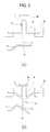
- FIG. 2is cross-sectional views of a double contact point switch according to a first exemplary embodiment of the present device.
- FIG. 3is cross-sectional views of a double contact point switch according to a second exemplary embodiment of the present device.
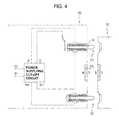
- FIG. 4is a conceptual diagram of a magnetic connector having a double contact point switch according to the present device.
- FIG. 5is illustrative views of contact terminals of the magnetic connector.
- FIG. 6is perspective views of the magnetic connector and a counter magnetic connector.
- FIG. 7is a cross-sectional view of the magnetic connector.
- a double contact point switch according to the present devicemay be implemented in several schemes, it may be implemented as in the following two exemplary embodiments.
- FIG. 2is cross-sectional views of a double contact point switch according to a first exemplary embodiment of the present device.
- FIG. 2shows (a) a form before a counter contact terminal presses the double contact point switch; and (b) a form after the counter contact terminal presses the double contact point switch.
- a pin part 10is provided with a front contact point 11 and a rear contact point 12 .
- the pin part 10is formed in a body part 20 , and is provided with a catching jaw 13 that prevents the pin part 10 from being separated from the body part 20 .
- the pin part 10has a spring 14 formed at a rear thereof, and elastic force of the spring 14 serves to push the pin part 10 forward.
- the pin part 10has an additional terminal part formed at the rear thereof, wherein the additional terminal part 30 is coupled to a connecting part 31 thereof.
- the counter contact terminal 40is a contact terminal formed in a magnetic connector of an opposite side.
- the counter contact terminal 40applies pressing force to the front contact point 11 of the pin part 10 while contacting the front contact point 11 .
- the pin part 10moves rearward, and the rear contact point 12 contacts the additional terminal part 30 .
- the connecting part 31 of the additional terminal part 30has elastic force, when external force is applied to the additional terminal part 30 , the additional terminal part 30 moves rearward, and when the external force disappears, the additional terminal part 30 again moves forward.
- the pin part 10is made of a material having conductivity, when the pin part 10 contacts the additional terminal part 30 and the counter contact terminal 40 as shown in (b) of FIG. 2 , the pin part 10 is electrically connected to the additional terminal part 30 and the counter contact terminal 40 .
- an electric wiremay be soldered directly to the pin part 10 in order to electrically connect the pin part 10 and the electric wire to each other.
- the spring 14 and the body part 20are made of materials having conductivity, a body protrusion part 21 is formed on the body part 20 , and the electric wire is connected to the body protrusion part 21 , thereby making it possible to electrically connect the pin part 10 and the electric wire to each other. That is, the pin part 10 and the body part 20 are electrically connected to each other, thereby making it possible to easily electrically connect the electric wire and the pin part 10 to each other.
- FIG. 3is cross-sectional views of a double contact point switch according to a second exemplary embodiment of the present device.
- FIG. 3shows (a) a form before a counter contact terminal presses the double contact point switch; and (b) a form after the counter contact terminal presses the double contact point switch.
- a pin part 10is provided with a front contact point 11 and a rear contact point 12 .
- the pin part 10has two wing parts 16 lengthily formed at sides thereof, wherein the two wing parts 16 are inserted into and fixed to fixing parts 25 . Since the wing part 16 is made of a material having elasticity, when external force is applied from the front to the pin part 10 , the pin part 10 moves rearward, and when the force applied from the front disappears, the pin part 10 returns to its original position.
- the pin part 10has an additional terminal part 30 formed at the rear thereof, wherein the additional terminal part 30 is coupled to a connecting part 31 thereof.
- the counter contact terminal 40is a contact terminal formed in a magnetic connector of an opposite side.
- the counter contact terminal 40applies pressing force to the front contact point 11 of the pin part 10 while contacting the front contact point 11 of the pin part 10 .
- the pin part 10moves rearward, and the rear contact point 12 contacts the additional terminal part 30 .
- the connecting part 31 of the additional terminal part 30has elastic force, when external force is applied to the additional terminal part 30 , the additional terminal part 30 moves rearward, and when the external force disappears, the additional terminal part 30 again moves forward.
- the pin part 10is made of a material having conductivity, when the pin part 10 contacts the additional terminal part 30 and the counter contact terminal 40 as shown in (b) of FIG. 3 , the pin part 10 is electrically connected to the additional terminal part 30 and the counter contact terminal 40 .
- the connecting part 31 of the additional terminal partis formed of a metal having elasticity to allow the additional terminal parts 30 of first and second exemplary embodiments to have elasticity
- other meansmay also be used in order to allow the additional terminal part 30 to have the elasticity.
- a coil springmay be attached to a rear surface of the additional terminal part 30 to allow the additional terminal part 30 to have the elasticity.
- various meansmay be used.
- the spring 14 of a first exemplary embodiment and the wing part 16 of a second exemplary embodimentare installed in order to allow the pin part 10 to have elasticity and serve as an elastic part (a part applying the elasticity to the pin part), an elastic part by other methods may also be installed.
- the meaning that the pin part 10 and the additional terminal part 30 have elastic forceis that when external force is applied from the front, the pin part 10 and the additional terminal part 30 move rearward in proportion to the external force, and when the external force disappears, the pin part 10 and the additional terminal part 30 again move forward.
- the reason why the pin part 10 and the additional terminal part 30 have the elastic forceis in order to allow the pin part 10 to certainly contact the counter contact terminal 40 and the additional terminal part 30 when the magnetic connector is connected.
- FIG. 4is a conceptual diagram of a magnetic connector having a double contact point switch according to the present device.
- the magnetic connector 50has a magnet 53 formed on a surface thereof, and magnetic attractive force acts between the magnet 53 and a magnet of a counter magnetic connector 70 to couple the two magnetic connectors to each other.
- a position of the magnet of the magnetic connectormay be variously changed depending on a demand in a design.
- the magnetic connector 50 of a power supplying apparatushas a power supplying cut-off circuit provided therein.
- the power supplying cut-off circuitcuts off outputs to Vo+ and Vo ⁇ when inputs P and S are not electrically connected to each other, but allows the outputs to Vo+ and Vo ⁇ when the inputs P and S are electrically connected to each other.
- the power supplying cut-off circuitallows the outputs to Vo+ and Vo ⁇ when a predetermined time elapses after the inputs P and S are not electrically connected to each other. Since the power supplying cut-off circuit is the well-known technology, a detailed description therefor will be omitted.
- the double contact point switchis installed in the contact terminal 51 in an exemplary embodiment of FIG. 4
- the double contact point switchmay be installed in the contact terminal 52 or the double contact point switches may be installed in both of the contact terminals 51 and 52 .
- outputs from the two double contact point switchesmay pass through an AND circuit or an OR circuit and be then sent as inputs of the power supplying cut-off circuit.
- the transformermay be operated only in the case in which the magnetic connector of the power supplying apparatus and a magnetic connector of the electronic apparatus are connected to each other using the double contact point switch.
- the number of power supplying terminals of the magnetic connectoris two (that is, positive (+) and negative ( ⁇ ) terminals) in FIG. 4
- a larger number of power supplying terminalsmay be installed to allow power to be supplied even in the case in which the magnetic connector 50 is rotated by 180 degrees.
- FIG. 5is illustrative views of contact terminals of the magnetic connector.
- the contact terminalsare formed symmetrically to each other in (a) and (b) of FIG. 5 , even though the magnetic connector 50 is rotated by 180 degrees in a state in which the counter magnetic connector 70 leaves as it is and is then connected to the counter magnetic connector 70 , power may be supplied through the power supplying terminals.
- FIG. 6is perspective views of the magnetic connector and a counter magnetic connector.
- (a) and (b) of FIG. 6are perspective views of the magnetic connector 50 having the contact terminals of (a) of FIG. 5 and the counter magnetic connector 70 .
- (a) and (b) of FIG. 6are perspective views viewed in opposite directions.
- FIG. 7is a cross-sectional view of the magnetic connector.
- FIG. 7is a cross-sectional view of the magnetic connector 50 of FIG. 6 .
- the double contact point switchesare installed in two contact terminals positioned at an outer side among the four contact terminals in FIG. 7
- the double contact point switchesmay be installed in two contact terminals positioned at the center or be installed in all of the four contact terminals.
- each of the double contact point switchesincludes the pin part 10 , the spring 14 , the body part 20 , and the additional terminal part 30 .
Landscapes
- Physics & Mathematics (AREA)
- Electromagnetism (AREA)
- Details Of Connecting Devices For Male And Female Coupling (AREA)
Abstract
Description
- 10: pin part
- 11: front contact point
- 12: rear contact point
- 13: catching jaw
- 14: spring
- 16: wing part
- 20: body part
- 21: body protrusion part
- 25: fixing part
- 30: additional terminal part
- 31: connecting part of additional terminal part
- 40: counter contact terminal
- 50: magnetic connector
- 51,52: contact terminal
- 53: magnet
- 70: counter magnetic connector
Claims (2)
Applications Claiming Priority (3)
| Application Number | Priority Date | Filing Date | Title |
|---|---|---|---|
| KR20-2014-0000383 | 2014-01-17 | ||
| KR2020140000383UKR200473045Y1 (en) | 2014-01-17 | 2014-01-17 | A double contact point switch and a magnetic connector having the double contact point switch |
| KR20-2014-0000383U | 2014-01-17 |
Publications (2)
| Publication Number | Publication Date |
|---|---|
| US20160006187A1 US20160006187A1 (en) | 2016-01-07 |
| US9431182B2true US9431182B2 (en) | 2016-08-30 |
Family
ID=51490430
Family Applications (1)
| Application Number | Title | Priority Date | Filing Date |
|---|---|---|---|
| US14/606,264Expired - Fee RelatedUS9431182B2 (en) | 2014-01-17 | 2015-01-27 | Double contact point switch and a magnetic connector having the double contact point switch |
Country Status (2)
| Country | Link |
|---|---|
| US (1) | US9431182B2 (en) |
| KR (1) | KR200473045Y1 (en) |
Cited By (12)
| Publication number | Priority date | Publication date | Assignee | Title |
|---|---|---|---|---|
| US9774137B2 (en)* | 2015-12-30 | 2017-09-26 | Lg Electronics Inc. | Mobile terminal |
| US10381782B2 (en) | 2017-06-12 | 2019-08-13 | Byrne Norman R | Electrical connector with haptic feedback |
| US10522943B1 (en)* | 2018-09-21 | 2019-12-31 | Calista A. Termini | Magnetically securing detachable electronic cable assembly and method |
| US10622756B1 (en)* | 2018-09-24 | 2020-04-14 | Apple Inc. | Gaskets for sealing spring-loaded contacts |
| USD890098S1 (en) | 2017-06-12 | 2020-07-14 | Norman R. Byrne | Electrical connector |
| US20210399466A1 (en)* | 2018-12-06 | 2021-12-23 | Microsoft Technology Licensing, Llc | Magnetic plug |
| USD955990S1 (en) | 2017-06-12 | 2022-06-28 | Norman R. Byrne | Electrical connector |
| US11374367B2 (en)* | 2020-09-29 | 2022-06-28 | Onanon, Inc. | Vibrating connector system |
| US11491884B2 (en) | 2017-01-19 | 2022-11-08 | Curtis Instruments Inc. | Magnetic charger connector for wheelchair |
| US20240106163A1 (en)* | 2022-09-28 | 2024-03-28 | Microsoft Technology Licensing, Llc | Retractable connector |
| US20240262222A1 (en)* | 2020-01-30 | 2024-08-08 | Seegrid Corporation | Vehicle charging head |
| US12368265B2 (en)* | 2020-04-07 | 2025-07-22 | Faisel ARFAOUI | Connection system for establishing a detachable electrically conductive connection, and connectors |
Families Citing this family (10)
| Publication number | Priority date | Publication date | Assignee | Title |
|---|---|---|---|---|
| US7311526B2 (en) | 2005-09-26 | 2007-12-25 | Apple Inc. | Magnetic connector for electronic device |
| USD684538S1 (en)* | 2012-06-08 | 2013-06-18 | Apple Inc. | Adapter |
| KR20160059270A (en)* | 2014-11-18 | 2016-05-26 | 삼성전자주식회사 | Electrical connector |
| KR102063936B1 (en)* | 2015-10-20 | 2020-01-08 | 주식회사 엘지화학 | Energy Storage System Comprising Battery Modules Connected by Magnetic Connecting Structure |
| KR101761596B1 (en)* | 2016-03-07 | 2017-07-26 | 주식회사 럭스로보 | Module assembly |
| CN107394490B (en)* | 2016-05-17 | 2021-01-26 | 富士康(昆山)电脑接插件有限公司 | Cable assembly with improved cable retention |
| JP2018055994A (en)* | 2016-09-29 | 2018-04-05 | Smk株式会社 | Socket arc discharge prevention structure |
| CN110197632B (en)* | 2019-02-26 | 2024-05-03 | 深圳市佛光照明有限公司 | Showing prop splicing device |
| US11424573B2 (en) | 2020-09-24 | 2022-08-23 | Apple Inc. | Magnetic connectors with self-centering floating contacts |
| US20220297798A1 (en)* | 2021-03-16 | 2022-09-22 | Tien Hsin Industries Co., Ltd. | Electronic derailleur |
Citations (15)
| Publication number | Priority date | Publication date | Assignee | Title |
|---|---|---|---|---|
| US3915536A (en)* | 1972-02-23 | 1975-10-28 | Hellzen Bertil | Holder for an electric lamp |
| US6224407B1 (en)* | 1997-12-17 | 2001-05-01 | The Whitaker Corporation | Coaxial switch connector assembly |
| US6506082B1 (en)* | 2001-12-21 | 2003-01-14 | Interconnect Devices, Inc. | Electrical contact interface |
| US6533593B1 (en)* | 1999-12-27 | 2003-03-18 | Yamaichi Electronics Co., Ltd. | Coaxial connector with selector switch |
| US20030060069A1 (en)* | 2001-08-31 | 2003-03-27 | Duquerroy Patrick M. | Coaxial connector for interconnecting printed circuit boards |
| US6937045B2 (en)* | 2002-07-18 | 2005-08-30 | Aries Electronics, Inc. | Shielded integrated circuit probe |
| US7311526B2 (en) | 2005-09-26 | 2007-12-25 | Apple Inc. | Magnetic connector for electronic device |
| US7322861B2 (en)* | 2005-11-23 | 2008-01-29 | Lear Corporation | Power supply circuit for removable automotive interior systems with integrated switching function |
| US20100221940A1 (en)* | 2009-02-27 | 2010-09-02 | Amphenol Corporation | Surface mount coaxial connector with switching function |
| US20110230105A1 (en)* | 2010-03-18 | 2011-09-22 | Hon Hai Precision Industry Co., Ltd. | Composite contact assembly having lower contact with contact engaging points offset from each other |
| US8523579B2 (en)* | 2007-09-18 | 2013-09-03 | Delaware Capital Formation, Inc. | Spring contact assembly |
| US20140057500A1 (en)* | 2011-12-29 | 2014-02-27 | Enplas Corporation | Electric contact pin and socket for electrical parts |
| US8758067B2 (en)* | 2010-06-03 | 2014-06-24 | Hsio Technologies, Llc | Selective metalization of electrical connector or socket housing |
| US8758066B2 (en)* | 2012-02-03 | 2014-06-24 | Interconnect Devices, Inc. | Electrical connector with insulation member |
| US8911266B2 (en)* | 2010-06-01 | 2014-12-16 | 3M Innovative Properties Company | Contact holder |
Family Cites Families (4)
| Publication number | Priority date | Publication date | Assignee | Title |
|---|---|---|---|---|
| KR200158414Y1 (en) | 1996-07-03 | 1999-10-15 | 양기선 | Connection pin assembly for connector inspection device |
| KR200196977Y1 (en)* | 1997-03-14 | 2000-10-02 | 강일수 | Safety outlet |
| KR200176766Y1 (en)* | 1997-06-30 | 2000-04-15 | 김태구 | Safety plug for charging electric vehicles |
| US7351066B2 (en)* | 2005-09-26 | 2008-04-01 | Apple Computer, Inc. | Electromagnetic connector for electronic device |
- 2014
- 2014-01-17KRKR2020140000383Upatent/KR200473045Y1/ennot_activeExpired - Lifetime
- 2015
- 2015-01-27USUS14/606,264patent/US9431182B2/ennot_activeExpired - Fee Related
Patent Citations (16)
| Publication number | Priority date | Publication date | Assignee | Title |
|---|---|---|---|---|
| US3915536A (en)* | 1972-02-23 | 1975-10-28 | Hellzen Bertil | Holder for an electric lamp |
| US6224407B1 (en)* | 1997-12-17 | 2001-05-01 | The Whitaker Corporation | Coaxial switch connector assembly |
| US6533593B1 (en)* | 1999-12-27 | 2003-03-18 | Yamaichi Electronics Co., Ltd. | Coaxial connector with selector switch |
| US20030060069A1 (en)* | 2001-08-31 | 2003-03-27 | Duquerroy Patrick M. | Coaxial connector for interconnecting printed circuit boards |
| US6506082B1 (en)* | 2001-12-21 | 2003-01-14 | Interconnect Devices, Inc. | Electrical contact interface |
| US6937045B2 (en)* | 2002-07-18 | 2005-08-30 | Aries Electronics, Inc. | Shielded integrated circuit probe |
| US7311526B2 (en) | 2005-09-26 | 2007-12-25 | Apple Inc. | Magnetic connector for electronic device |
| US7322861B2 (en)* | 2005-11-23 | 2008-01-29 | Lear Corporation | Power supply circuit for removable automotive interior systems with integrated switching function |
| US8523579B2 (en)* | 2007-09-18 | 2013-09-03 | Delaware Capital Formation, Inc. | Spring contact assembly |
| US20100221940A1 (en)* | 2009-02-27 | 2010-09-02 | Amphenol Corporation | Surface mount coaxial connector with switching function |
| US20110230105A1 (en)* | 2010-03-18 | 2011-09-22 | Hon Hai Precision Industry Co., Ltd. | Composite contact assembly having lower contact with contact engaging points offset from each other |
| US8911266B2 (en)* | 2010-06-01 | 2014-12-16 | 3M Innovative Properties Company | Contact holder |
| US8758067B2 (en)* | 2010-06-03 | 2014-06-24 | Hsio Technologies, Llc | Selective metalization of electrical connector or socket housing |
| US20140057500A1 (en)* | 2011-12-29 | 2014-02-27 | Enplas Corporation | Electric contact pin and socket for electrical parts |
| US9048556B2 (en)* | 2011-12-29 | 2015-06-02 | Emplas Corporation | Electric contact pin and socket for electrical parts |
| US8758066B2 (en)* | 2012-02-03 | 2014-06-24 | Interconnect Devices, Inc. | Electrical connector with insulation member |
Cited By (20)
| Publication number | Priority date | Publication date | Assignee | Title |
|---|---|---|---|---|
| US9774137B2 (en)* | 2015-12-30 | 2017-09-26 | Lg Electronics Inc. | Mobile terminal |
| US11491884B2 (en) | 2017-01-19 | 2022-11-08 | Curtis Instruments Inc. | Magnetic charger connector for wheelchair |
| US12083908B2 (en) | 2017-01-19 | 2024-09-10 | Curtis Instruments, Inc. | Magnetic charger connector for wheelchair |
| US10381782B2 (en) | 2017-06-12 | 2019-08-13 | Byrne Norman R | Electrical connector with haptic feedback |
| USD1090438S1 (en) | 2017-06-12 | 2025-08-26 | Norman R. Byrne | Electrical connector |
| USD890098S1 (en) | 2017-06-12 | 2020-07-14 | Norman R. Byrne | Electrical connector |
| USD924152S1 (en) | 2017-06-12 | 2021-07-06 | Norman R. Byrne | Electrical connector |
| USD924159S1 (en) | 2017-06-12 | 2021-07-06 | Norman R. Byrne | Electrical connector |
| USD955990S1 (en) | 2017-06-12 | 2022-06-28 | Norman R. Byrne | Electrical connector |
| US10522943B1 (en)* | 2018-09-21 | 2019-12-31 | Calista A. Termini | Magnetically securing detachable electronic cable assembly and method |
| US20240291195A1 (en)* | 2018-09-21 | 2024-08-29 | Calista A. Termini | Magnetically securing detachable electronic cable assembly and method |
| US10931058B2 (en) | 2018-09-24 | 2021-02-23 | Apple Inc. | Gaskets for sealing spring-loaded contacts |
| US10622756B1 (en)* | 2018-09-24 | 2020-04-14 | Apple Inc. | Gaskets for sealing spring-loaded contacts |
| US11791591B2 (en)* | 2018-12-06 | 2023-10-17 | Microsoft Technology Licensing, Llc | Magnetic plug |
| US20210399466A1 (en)* | 2018-12-06 | 2021-12-23 | Microsoft Technology Licensing, Llc | Magnetic plug |
| US20240262222A1 (en)* | 2020-01-30 | 2024-08-08 | Seegrid Corporation | Vehicle charging head |
| US12221000B2 (en) | 2020-01-30 | 2025-02-11 | Seegrid Corporation | Vehicle auto-charging system and method |
| US12368265B2 (en)* | 2020-04-07 | 2025-07-22 | Faisel ARFAOUI | Connection system for establishing a detachable electrically conductive connection, and connectors |
| US11374367B2 (en)* | 2020-09-29 | 2022-06-28 | Onanon, Inc. | Vibrating connector system |
| US20240106163A1 (en)* | 2022-09-28 | 2024-03-28 | Microsoft Technology Licensing, Llc | Retractable connector |
Also Published As
| Publication number | Publication date |
|---|---|
| KR200473045Y1 (en) | 2014-06-27 |
| US20160006187A1 (en) | 2016-01-07 |
Similar Documents
| Publication | Publication Date | Title |
|---|---|---|
| US9431182B2 (en) | Double contact point switch and a magnetic connector having the double contact point switch | |
| US8734165B2 (en) | Quick connection device for electrical appliance | |
| US9312632B2 (en) | Heat resistant magnetic electrical connector | |
| US7607920B1 (en) | Connecting device for interconnecting electronic devices | |
| US9419377B2 (en) | Dual orientation electrical connector assembly | |
| KR102080435B1 (en) | Multpurpose electrical charging structure | |
| JP2015111590A (en) | Magnetic connector module having power supply blocking circuit | |
| US7204695B1 (en) | Fastener structure | |
| JP4697308B2 (en) | Mounting detection structure for small electrical equipment | |
| CN203445280U (en) | Electric connector | |
| CN107078422A (en) | Electric connector | |
| CN109818213A (en) | Connector Assemblies and Electronics | |
| US11296457B2 (en) | Magnetic connector | |
| CN112868079B (en) | Contactor with arc suppressor | |
| JP2016100106A (en) | Magnet type connector for dc power supply unit | |
| TW201635657A (en) | Magnetic electrical connector and plug of same | |
| US8810342B2 (en) | Electromagnetic relay | |
| US20190067977A1 (en) | Magnetic charging device capable of wireless charging | |
| JP2018018836A (en) | Contact structure of contact | |
| WO2022102344A1 (en) | Connection device and electric module | |
| KR101438582B1 (en) | High current electrical connector | |
| US10063017B2 (en) | Connector | |
| JP2010073353A (en) | Interface connector and plug | |
| JP6296037B2 (en) | Contact structure | |
| JP6198018B2 (en) | Magnetic bonding type connector |
Legal Events
| Date | Code | Title | Description |
|---|---|---|---|
| AS | Assignment | Owner name:SPS INC., KOREA, REPUBLIC OF Free format text:ASSIGNMENT OF ASSIGNORS INTEREST;ASSIGNORS:KIM, JUNG GYO;JEON, EUN-MIN;YOUN, DAE-YOUNG;AND OTHERS;REEL/FRAME:035499/0580 Effective date:20150417 | |
| FEPP | Fee payment procedure | Free format text:PAYOR NUMBER ASSIGNED (ORIGINAL EVENT CODE: ASPN); ENTITY STATUS OF PATENT OWNER: SMALL ENTITY | |
| ZAAA | Notice of allowance and fees due | Free format text:ORIGINAL CODE: NOA | |
| ZAAB | Notice of allowance mailed | Free format text:ORIGINAL CODE: MN/=. | |
| STCF | Information on status: patent grant | Free format text:PATENTED CASE | |
| MAFP | Maintenance fee payment | Free format text:PAYMENT OF MAINTENANCE FEE, 4TH YR, SMALL ENTITY (ORIGINAL EVENT CODE: M2551); ENTITY STATUS OF PATENT OWNER: SMALL ENTITY Year of fee payment:4 | |
| FEPP | Fee payment procedure | Free format text:MAINTENANCE FEE REMINDER MAILED (ORIGINAL EVENT CODE: REM.); ENTITY STATUS OF PATENT OWNER: SMALL ENTITY | |
| LAPS | Lapse for failure to pay maintenance fees | Free format text:PATENT EXPIRED FOR FAILURE TO PAY MAINTENANCE FEES (ORIGINAL EVENT CODE: EXP.); ENTITY STATUS OF PATENT OWNER: SMALL ENTITY | |
| STCH | Information on status: patent discontinuation | Free format text:PATENT EXPIRED DUE TO NONPAYMENT OF MAINTENANCE FEES UNDER 37 CFR 1.362 | |
| FP | Lapsed due to failure to pay maintenance fee | Effective date:20240830 |