US9431044B1 - Slider having shock and particle resistance - Google Patents
Slider having shock and particle resistanceDownload PDFInfo
- Publication number
- US9431044B1 US9431044B1US14/307,067US201414307067AUS9431044B1US 9431044 B1US9431044 B1US 9431044B1US 201414307067 AUS201414307067 AUS 201414307067AUS 9431044 B1US9431044 B1US 9431044B1
- Authority
- US
- United States
- Prior art keywords
- leading
- air bearing
- bearing surface
- slider
- surface portion
- Prior art date
- Legal status (The legal status is an assumption and is not a legal conclusion. Google has not performed a legal analysis and makes no representation as to the accuracy of the status listed.)
- Expired - Fee Related
Links
- 230000035939shockEffects0.000titledescription6
- 239000002245particleSubstances0.000titledescription5
- 230000001788irregularEffects0.000claimsdescription3
- 238000011144upstream manufacturingMethods0.000description20
- 238000000034methodMethods0.000description7
- PNEYBMLMFCGWSK-UHFFFAOYSA-Naluminium oxideInorganic materials[O-2].[O-2].[O-2].[Al+3].[Al+3]PNEYBMLMFCGWSK-UHFFFAOYSA-N0.000description4
- 238000004519manufacturing processMethods0.000description4
- 230000002411adverseEffects0.000description3
- 230000008901benefitEffects0.000description3
- 230000008569processEffects0.000description3
- 230000003287optical effectEffects0.000description2
- 230000009467reductionEffects0.000description2
- MTPVUVINMAGMJL-UHFFFAOYSA-Ntrimethyl(1,1,2,2,2-pentafluoroethyl)silaneChemical compoundC[Si](C)(C)C(F)(F)C(F)(F)FMTPVUVINMAGMJL-UHFFFAOYSA-N0.000description2
- 230000009286beneficial effectEffects0.000description1
- 229910010293ceramic materialInorganic materials0.000description1
- 230000008859changeEffects0.000description1
- 238000011109contaminationMethods0.000description1
- 238000013016dampingMethods0.000description1
- 230000001627detrimental effectEffects0.000description1
- 238000010586diagramMethods0.000description1
- 230000005672electromagnetic fieldEffects0.000description1
- 230000001939inductive effectEffects0.000description1
- 239000000463materialSubstances0.000description1
- 238000012986modificationMethods0.000description1
- 230000004048modificationEffects0.000description1
- 230000002265preventionEffects0.000description1
- 230000035945sensitivityEffects0.000description1
- 230000005641tunnelingEffects0.000description1
Images


Classifications
- G—PHYSICS
- G11—INFORMATION STORAGE
- G11B—INFORMATION STORAGE BASED ON RELATIVE MOVEMENT BETWEEN RECORD CARRIER AND TRANSDUCER
- G11B5/00—Recording by magnetisation or demagnetisation of a record carrier; Reproducing by magnetic means; Record carriers therefor
- G11B5/48—Disposition or mounting of heads or head supports relative to record carriers ; arrangements of heads, e.g. for scanning the record carrier to increase the relative speed
- G11B5/58—Disposition or mounting of heads or head supports relative to record carriers ; arrangements of heads, e.g. for scanning the record carrier to increase the relative speed with provision for moving the head for the purpose of maintaining alignment of the head relative to the record carrier during transducing operation, e.g. to compensate for surface irregularities of the latter or for track following
- G11B5/60—Fluid-dynamic spacing of heads from record-carriers
- G—PHYSICS
- G11—INFORMATION STORAGE
- G11B—INFORMATION STORAGE BASED ON RELATIVE MOVEMENT BETWEEN RECORD CARRIER AND TRANSDUCER
- G11B5/00—Recording by magnetisation or demagnetisation of a record carrier; Reproducing by magnetic means; Record carriers therefor
- G11B5/127—Structure or manufacture of heads, e.g. inductive
- G11B5/187—Structure or manufacture of the surface of the head in physical contact with, or immediately adjacent to the recording medium; Pole pieces; Gap features
- G11B5/1871—Shaping or contouring of the transducing or guiding surface
- G—PHYSICS
- G11—INFORMATION STORAGE
- G11B—INFORMATION STORAGE BASED ON RELATIVE MOVEMENT BETWEEN RECORD CARRIER AND TRANSDUCER
- G11B5/00—Recording by magnetisation or demagnetisation of a record carrier; Reproducing by magnetic means; Record carriers therefor
- G11B5/48—Disposition or mounting of heads or head supports relative to record carriers ; arrangements of heads, e.g. for scanning the record carrier to increase the relative speed
- G11B5/58—Disposition or mounting of heads or head supports relative to record carriers ; arrangements of heads, e.g. for scanning the record carrier to increase the relative speed with provision for moving the head for the purpose of maintaining alignment of the head relative to the record carrier during transducing operation, e.g. to compensate for surface irregularities of the latter or for track following
- G11B5/60—Fluid-dynamic spacing of heads from record-carriers
- G11B5/6005—Specially adapted for spacing from a rotating disc using a fluid cushion
- G11B5/6082—Design of the air bearing surface
- G—PHYSICS
- G11—INFORMATION STORAGE
- G11B—INFORMATION STORAGE BASED ON RELATIVE MOVEMENT BETWEEN RECORD CARRIER AND TRANSDUCER
- G11B5/00—Recording by magnetisation or demagnetisation of a record carrier; Reproducing by magnetic means; Record carriers therefor
- G11B5/48—Disposition or mounting of heads or head supports relative to record carriers ; arrangements of heads, e.g. for scanning the record carrier to increase the relative speed
- G11B5/58—Disposition or mounting of heads or head supports relative to record carriers ; arrangements of heads, e.g. for scanning the record carrier to increase the relative speed with provision for moving the head for the purpose of maintaining alignment of the head relative to the record carrier during transducing operation, e.g. to compensate for surface irregularities of the latter or for track following
- G11B5/60—Fluid-dynamic spacing of heads from record-carriers
- G11B5/6005—Specially adapted for spacing from a rotating disc using a fluid cushion
Definitions
- Information storage devicesare used to retrieve and/or store data in computers and other consumer electronics devices.
- a magnetic hard disk driveis an example of an information storage device that includes one or more heads that can both read and write.
- each read headtypically comprises a body called a “slider” that carries a magnetic transducer on its trailing end.
- the magnetic transducertypically comprises a writer and a read element.
- the magnetic transducer's writermay be of a longitudinal or perpendicular design, and the read element of the magnetic transducer may be inductive or magnetoresistive (e.g. so-called “giant” magneto-resistive read element, tunneling magneto-resistive read element, etc).
- the transduceris typically supported in very close proximity to the magnetic disk by a hydrodynamic air bearing.
- the hydrodynamic air bearingis formed between an air bearing surface of the slider of the read head, and a surface of the magnetic disk.
- the thickness of the air bearing at the location of the transduceris commonly referred to as “flying height.”
- Magnetic hard disk drivesare not the only type of information storage devices that have utilized air bearing sliders.
- air bearing slidershave also been used in optical information storage devices to position a mirror and an objective lens for focusing laser light on the surface of disk media that is not necessarily magnetic.
- the flying heightis a parameter that affects the performance of an information storage device. If the flying height is too high, the ability of the transducer to write and/or read information to/from the disk surface may be substantially degraded. Therefore, reductions in flying height can facilitate desirable increases in the areal density of data stored on a disk surface. However, it is not beneficial to eliminate the air bearing between the slider and the disk surface entirely, because the air bearing serves to reduce friction and wear (between the slider and the disk surface) to an acceptable level. Excessive reduction in the nominal flying height may degrade the tribological performance of the disk drive to the point where the lifetime and reliability of the disk drive become unacceptable.
- Air bearing features that discourage the entry of particulate debrishave been proposed before.
- past air bearing design features that discourage the entry of particulate debrishave been detrimental to the flying characteristics of the slider, for example reducing super-ambient pressure in key regions of the air bearing and thereby unacceptably reducing the load carrying capacity of the air bearing.
- Certain such design featurescan also adversely affect the ability of the air bearing to maintain an acceptable roll angle in the face of expected changes to the skew angle of the slider (relative to the direction of disk surface motion). Such skew angle changes are expected as the actuator positions the read head to different disk radii.
- the shortcomings of contemporary air bearing design features to discourage entry of particlesmay be exacerbated in sliders having a smaller air bearing area, such as newer smaller-form factor sliders (e.g. the so-called “femto” form factor).
- FIG. 1is a top view of an exemplary embodiment of a hard disk drive.
- FIG. 2is an exemplary embodiment of a head gimbal assembly including an exemplary embodiment of a slider.
- FIG. 3is a perspective view of an exemplary embodiment of a slider.
- FIG. 4is a plan view of the exemplary embodiment of the slider of FIG. 3 .
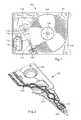
- FIG. 5is a cross section view of the exemplary embodiment of the slider of FIG. 4 taken along line 5 - 5 .
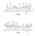
- FIG. 6is a cross section view of the exemplary embodiment of the slider of FIG. 5 taken along line 6 - 6 .
- any reference to an element herein using a designation such as “first,” “second,” and so forthdoes not generally limit the quantity or order of those elements. Rather, these designations are used herein as a convenient method of distinguishing between two or more elements or instances of an element. Thus, a reference to first and second elements does not mean that only two elements can be employed, or that the first element must precede the second element.
- a slider for a hard diskincludes a leading structure having a first air bearing surface portion, a trailing structure having a second air bearing surface portion, and a cavity between the leading structure and the trailing structure.
- the leading structurehas one or more interior walls defining a pit therein.
- a hard disk driveincludes a rotatable magnetic recording disk and a slider for use with the magnetic recording disk.
- the sliderincludes a leading structure having a first air bearing surface portion, a trailing structure having a second air bearing surface portion, and a cavity between the leading structure and the trailing structure.
- the leading structurehas one or more interior walls defining a pit therein.
- FIG. 1shows a hard disk drive 100 including a disk drive base 102 , at least one disk 104 (such as a magnetic disk, magneto-optical disk, or optical disk), a spindle motor 106 attached to the base 102 for rotating the disk 104 , and a head stack assembly (HSA) 110 .
- the spindle motor 106typically includes a rotating hub on which disks are mounted and clamped, a magnet attached to the hub, and a stator. Various coils of the stator are selectively energized to form an electromagnetic field that pulls/pushes on the magnet, thereby rotating the hub. Rotation of the spindle motor hub results in rotation of the mounted disks.
- the HSA 110typically includes at least one actuator arm 114 , and at least one head gimbal assembly (HGA) 124 that includes a read head.
- HGAhead gimbal assembly
- the HSA 110rotates to position the read head along an arc adjacent desired information tracks on the disk 104 .
- the HSA 110includes a pivot bearing cartridge 118 to facilitate such rotational positioning.
- the HSA 110typically includes a voice coil that interacts with one or more fixed magnets on a magnetic yoke 112 , to rotate the HSA 110 .
- the HSA 110is rotated such that the HGA 124 leaves a ramp 120 , the read head is loaded onto a surface of the disk 104 .
- Other disk drive components shown in FIG. 1include a flex cable bracket 116 and a recirculation air filter 108 .
- FIG. 2shows a head gimbal assembly (HGA) 200 that includes a load beam 202 , a laminated flexure 204 , and a swage mount 206 .
- the HGA 200also includes a slider 210 in accordance with an embodiment of the present invention, which is bonded to a tongue of the laminated flexure 204 .
- the laminated flexure 204provides structural support and compliance to the slider 210 , and also provides a plurality of electrically conductive traces 218 , preferably including traces for carrying electrical signals from/to a read/write transducer of head 210 .
- FIG. 3is a perspective view of an exemplary embodiment of a slider 300 .
- the slider featuresare not to scale but rather are exaggerated so as to be easily discernible.
- FIG. 4is a plan view of the slider 300 .
- the slider 300may include a transducer 302 for at least reading information from an adjacent disk surface.
- the slider 300may also include a base 304 , which is typically fabricated from a ceramic material such as alumina titanium carbide.
- the slider 300may have a leading edge 306 and a trailing edge 308 that is opposite the leading edge.
- the slider 300may also have a first air bearing surface portion 310 and a second air bearing surface portion 311 , each of which is normal to the trailing edge 308 .
- Other devices and transducersmay also be disposed on or adjacent the trailing face, in addition to the read transducer.
- the read transducermay be part of a merged transducer that also includes a write transducer.
- the air bearing surface 310defines an upstream direction (e.g. 312 ) pointing from the trailing edge 308 to the leading edge 306 .
- upstreamis used herein only to define a directional convention to facilitate description of relative positions on the air bearing surface, and does not require the presence or existence of any stream.
- upstreamcan be understood to refer to a range of directions across the air bearing surface 310 that generally point away from the trailing edge 308 and towards the leading edge 306 .
- upstream directionswould ultimately be generally opposite the motion of an adjacent rotating disk surface.
- An upstream directionwould be a direction within the aforementioned range.
- downstreamis used herein as an antonym of “upstream.”
- the air bearing surface 310defines a lateral axis that is orthogonal to that upstream direction.
- the air bearing surface 310defines a corresponding lateral axis 314 that is parallel to the leading edge 306 or the trailing edge 308 (i.e. orthogonal to that upstream direction).
- the width of the slidercan be measured along lateral axis.
- so-called “femto” form factor sliderswould then typically have a width of 0.70 mm and a length of 0.85 mm
- so-called “pico” form factor sliderswould then typically have a width of 1.00 mm and a length of 1.25 mm.
- Non-zero skew upstream directionsare also contemplated herein.
- the features of air bearing surfaceare not to scale in FIG. 3 , but rather are vertically exaggerated (i.e. exaggerated in a direction normal to both the upstream direction and the lateral axis) so as to be easily discernible.
- the slider 300may include a leading structure 316 and a trailing structure 318 , which may be separated by deep cavities 320 , also referred herein as sub-ambient pressure cavities 320 .
- the deep cavities 320may be located between and separate the leading structure 316 from the trailing structure 318 .
- the deep cavities 320may provide an area of sub-ambient pressure in operation.
- the trailing structure 318may include a trailing pad 322 .
- the trailing pad 322may include a surface 324 adjacent the read transducer 302 . As shown in FIG.
- the surface 324 of the trailing pad 322may lie in a plane, where the plane is the farthest plane from the slider body 304 relative to the other features of the slider 300 .
- the term “plane” used hereinthus refers to the plane in which the surface 324 of the trailing pad 322 lies.
- the plane in which the surface 324 liesmay be the closest plane to the media relative in use, relative to the other slider features.
- the air bearing surface 310is located along the surface 324 and thus lies in the plane.
- the sub-ambient pressure cavities 320may be recessed relative to the plane/air bearing surface 310 by about 500 nm or more.
- the transducer 302may include an overcoat material (e.g. alumina) that is incidentally slightly recessed from the plane, because alumina may etch away more rapidly than does alumina titanium carbide during fabrication of the air bearing.
- an overcoat materiale.g. alumina
- the trailing pad 322may develop a super-ambient pressure region between the air bearing surface and the surface of an adjacent disk that can help maintain a desired flying height at the location of transducer.
- the trailing pad 322may create a region of high pressure, including the highest pressure generated by the air bearing surface 310 during normal operation of the head.
- a pressurizing step 326may located upstream of the trailing pad 322 .
- the pressurizing step 326preferably includes a surface that is recessed relative to the plane/air bearing surface by about 100 nm to about 250 nm.
- the pressurizing step 326can enhance the super-ambient pressure between the trailing pad 322 and the surface of an adjacent disk. Such enhanced pressurization may reduce the surface area required for the trailing pad 322 .
- the air bearing surface 310may include stepped sub-ambient pressure cavities 330 .
- the stepped sub-ambient pressure cavities 330may include two distinct portions of different depth: a deep portion 334 and a shallow portion 336 .
- the deep portion 334 of the stepped sub-ambient pressure cavities 330may be recessed relative to the plane/air bearing surface by about 800 nm or more, for example from about 800 to about 2000 nm.
- the deep portion 334may be less recessed as compared to a pit 350 , which is discussed in more detail below.
- the shallow portion 336 of the stepped sub-ambient pressure cavities 330may be recessed relative to the plane/air bearing surface by about 300 nm or more, for example from about 300 nm to about 800 nm.
- the shallow portion 336may be more recessed than the pressuring step 326 .
- the shallow portion 336may be located downstream of the deep portion 334 and adjacent to the trailing pad 322 .
- one or more of these sub-ambient pressure cavities 320 , 330can develop a sub-ambient pressure region between the air bearing surface 310 and the surface of an adjacent disk.
- the sub-ambient pressuremay serve to reduce flying height sensitivities to changes in altitude and air bearing geometries.
- the stepped sub-ambient pressure cavities 330have been found to provide an optimal balance between shock damage prevention and maintaining altitude performance.
- the leading structure 326 of the air bearing surface 310may include two leading pads 342 also having a surface 344 in the plane (i.e., the surface 344 is in the same plane as the surface 324 ) and disposed upstream of the sub-ambient pressure cavities 320 .
- the two leading pads 342 togethermay span at least 60% of the width of the slider.
- the two leading pads 342may be shaped and adjoined together to form a shape like a letter W that is oriented so that the center peak 346 of the W points in the upstream direction, as shown in FIGS. 3 and 4 .
- the center peak 346 of the Wmay have a substantially rectangular U shape (e.g., two vertical legs 354 joined by a horizontal base leg 356 ) so as to define a pit 350 , which is described in more detail below. Furthermore, as shown in FIGS. 3 and 4 , the center peak 346 of the W may terminate at the leading edge 306 .
- the leading pads 342can develop a super-ambient pressure region between the air bearing surface 310 and the surface of an adjacent disk, causing the slider to assume a positive pitch attitude.
- the leading padsalso include leading pressurizing steps 348 .
- the leading pressurizing steps 348preferably include a surface that is recessed relative to plane/air bearing surface by about 100 nm or more, for example between about 100 nm to about 250 nm. During operation, the leading pressurizing steps 348 can help develop super-ambient pressure between the leading pads 342 and the surface of an adjacent disk.
- the leading padsalso include secondary leading pressurizing steps 349 and trailing pressurizing steps 338 .
- the secondary leading pressurizing steps 349 and the trailing pressuring steps 338preferably include surfaces that are recessed relative to the plane/air bearing surface by about 100 nm or more, for example between about 100 nm to about 250 nm.
- the secondary leading pressurizing steps 349can help develop super-ambient pressure between the leading pads 342 and the surface of an adjacent disk.
- the slider 300includes trenches 360 disposed upstream of the leading pads 342 .
- the trenches 360may be recessed relative to the plane/air bearing surface by about 600 nm or more, preferably about 800 nm or more.
- the trenchesmay be recessed by about 600 nm to about 2000 nm, more preferably from about 800 nm to about 1500 nm.
- the trenches 360may be disposed adjacent to the center peak 346 of the leading pads 342 .
- the trenches 360may be disposed adjacent the base leg 356 of the rectangular U shape (e.g., may extend parallel to the base leg 356 ).
- the trenches 360are non-continuous (e.g., comprise two separate trenches). Each of the trenches 360 may extend about 1 ⁇ 3 the width of the slider base 304 . Thus, together, the trenches 360 may extend about 2 ⁇ 3 the width of the slider base 304 .
- the trenches 360may help facilitate control of the so-called “roll profile.”
- the roll profileis the variation of slider roll angle, over a range of skew angles and velocities (relative to the motion of an adjacent disk) that correspond to variation in the position of the slider from the disk inner diameter to the disk outer diameter during operation of the disk drive.
- “flattening” of the roll profilee.g.
- the trenches 360may have an extent measured along the upstream direction that is at least 25 microns and no more than 8% of the total slider length measured along the upstream direction. These dimensional limits may avoid undesirable fabrication process consequences (e.g. due to tolerance stack-up), and/or to allow air flow having a lateral component through the trenches (sufficiently to adequately pressurize the air bearing surface).
- the slider 300may include a pit 350 recessed relative to the plane/air bearing surface and disposed adjacent the leading face 306 .
- “adjacent”means only that there is no air bearing feature in the plane that is closer than the “adjacent” feature.
- the pit 350helps prevent particulate contamination from entering the air bearing and also increases shock resistance.
- the pit 350may be recessed relative to the plane/air bearing surface by about 600 nm or more, more preferably about 1000 nm or more.
- the pitmay be recessed from about 600 nm to about 2500 nm, more preferably from about 1000 nm to about 2000 nm.
- the pit 350may be recessed by the same amount or greater than the recess of the trenches 360 .
- the pit 350may have a polygonal shape.
- the pit 350is formed as a six sided polygon, i.e., a hexagon.
- the pit 350may be an irregular hexagon, i.e., not all of the sides have the same length.
- the pit 350may continuously laterally span at least 25% of the width of the slider base 304 . This size may ensure adequate particle capture over a practical range of skew angles, while allowing sufficient airflow around the pit to adequately pressurize the air bearing surface over a practical range of skew angles. As shown in FIG.
- the pit 350may be at least partially defined the leading pad 342 of the leading structure 316 .
- the pit 350may be at least partially defined by the steps 349 of the leading structure.
- two of the side walls defining the pit 350may be part of the steps 349 .
- the walls that define the pit 350may be interior walls of the leading structure 316 .
- the pit 350may be centered along the width of the slider base 304 .
- the pit 350preferably has an extent measured along the upstream direction that is about 50 to about 100 microns and about 10-20% of the total slider base 304 length measured along the upstream direction. These dimensional limits may avoid undesirable fabrication process consequences (e.g. due to tolerance stack-up), and/or to allow sufficient air flow having a lateral component immediately downstream of the pit, to adequately pressurize the air bearing surface.
- the combination of the pit 350 and trenches 360adequately captures particles and increase shock resistance.
- the pit 350in particular contributes to shock resistance.
- the combination of trenches 360 and the pit 350 at the leading edge 306increases the suction force and damping, thus increasing shock resistance.
- the slider 300optionally may include two leading outboard dots 370 in the primary plane.
- Each leading outboard dot 370preferably defines a dot radius in the range 10 microns to 45 microns.
- Each leading outboard dot 370is adjacent the leading face 306 , adjacent a corner of the air bearing surface 310 , and laterally adjacent a trench 360 .
- the leading outboard dots 370may serve to prevent damage to the head disk interface under certain conditions that would otherwise lead to contact between a corner of the slider and an adjacent disk surface.
- FIGS. 5 and 6are cross-sectional views of the slider 300 shown in FIG. 4 , taken along the 5 - 5 and 6 - 6 in FIG. 4 , respectively.
- the step heightsare not to scale but rather are exaggerated so as to be easily discernible.
- the trailing pad 322 and the leading pad 342includes surfaces that are not recessed and instead establishes an air bearing surface datum plane (referred above as the “plane”) 500 , from which the recession of other surfaces of the slider 300 that are parallel to the plane 500 may be measured.
- planeair bearing surface datum plane
- the pit 350includes a surface in a plane 510 that is recessed relative to the plane 500 /air bearing surface by a recession depth 560 .
- the sub-ambient pressure cavities 320each include a surface in the plane 510 by a deep cavity recession depth 560 .
- the pit 350 depth and the sub-ambient pressure cavities 320 depthare discussed above.
- the deep portions 334 of the stepped pressure cavities 318include a surface in the plane 510 .
- the shallow portion 336 of the stepped pressure cavities 318include a surface in an intermediate plane 520 that lies between the plane 500 and the plane 510 , and that is recessed from the plane 500 by a recession depth 570 .
- the depth of both the deep portion 334 and the shallow portion 336are discussed above.
- the leading pressurizing steps 348 and the secondary leading pressuring steps 349may each include a surface in a plane 530 that may lie between the plane 500 and the intermediate plane 520 .
- the plane 530may be recessed from the primary 500 by depth 580 . The depth of the leading pressuring steps 348 and the secondary leading pressuring steps 349 are described above.
Landscapes
- Engineering & Computer Science (AREA)
- Manufacturing & Machinery (AREA)
- Adjustment Of The Magnetic Head Position Track Following On Tapes (AREA)
Abstract
Description
Claims (28)
Priority Applications (1)
| Application Number | Priority Date | Filing Date | Title |
|---|---|---|---|
| US14/307,067US9431044B1 (en) | 2014-05-07 | 2014-06-17 | Slider having shock and particle resistance |
Applications Claiming Priority (2)
| Application Number | Priority Date | Filing Date | Title |
|---|---|---|---|
| US201461989617P | 2014-05-07 | 2014-05-07 | |
| US14/307,067US9431044B1 (en) | 2014-05-07 | 2014-06-17 | Slider having shock and particle resistance |
Publications (1)
| Publication Number | Publication Date |
|---|---|
| US9431044B1true US9431044B1 (en) | 2016-08-30 |
Family
ID=56739927
Family Applications (1)
| Application Number | Title | Priority Date | Filing Date |
|---|---|---|---|
| US14/307,067Expired - Fee RelatedUS9431044B1 (en) | 2014-05-07 | 2014-06-17 | Slider having shock and particle resistance |
Country Status (1)
| Country | Link |
|---|---|
| US (1) | US9431044B1 (en) |
Cited By (3)
| Publication number | Priority date | Publication date | Assignee | Title |
|---|---|---|---|---|
| US10041184B2 (en)* | 2016-08-08 | 2018-08-07 | Seagate Technology Llc | Method of forming one or more metal and/or metal alloy layers in processes for making tranducers in sliders, and related sliders |
| US20200020355A1 (en)* | 2018-07-12 | 2020-01-16 | Sae Magnetics (H.K.) Ltd. | Air-Bearing Surface (ABS) Design to Reduce Particle Scratch Risk |
| US12009016B2 (en)* | 2022-05-20 | 2024-06-11 | Kabushiki Kaisha Toshiba | Magnetic head and magnetic disk device comprising the same |
Citations (147)
| Publication number | Priority date | Publication date | Assignee | Title |
|---|---|---|---|---|
| US5490025A (en) | 1994-12-08 | 1996-02-06 | International Business Machines Corporation | Air bearing slider with debris deflecting features |
| US5940249A (en) | 1997-11-10 | 1999-08-17 | International Business Machines Corporation | Shielded air bearing slider |
| US6075673A (en) | 1997-05-05 | 2000-06-13 | Read-Rite Corporation | Composite slider design |
| US6097575A (en) | 1998-07-14 | 2000-08-01 | Read-Rite Corporation | Composite slider with housing and interlocked body |
| US6125014A (en) | 1998-06-26 | 2000-09-26 | Read-Rite Corporation | Via-less connection using interconnect traces between bond pads and a transducer coil of a magnetic head slider |
| US6125015A (en) | 1998-12-04 | 2000-09-26 | Read-Rite Corporation | Head gimbal assembly with low stiffness flex circuit and ESD Protection |
| US6130863A (en) | 1997-11-06 | 2000-10-10 | Read-Rite Corporation | Slider and electro-magnetic coil assembly |
| US6137656A (en) | 1998-10-26 | 2000-10-24 | Read-Rite Corporation | Air bearing slider |
| US6144528A (en) | 1998-10-26 | 2000-11-07 | Read-Rite Corporation | Air bearing slider with reduced stiction |
| US6147838A (en) | 1997-02-10 | 2000-11-14 | Read-Rite Corporation | Air bearing slider with shaped taper |
| US6151196A (en) | 1999-02-16 | 2000-11-21 | Read-Rite Corporation | Magnetic head suspension assembly including an intermediate flexible member that supports an air bearing slider with a magnetic transducer for testing |
| US6181673B1 (en) | 1996-07-30 | 2001-01-30 | Read-Rite Corporation | Slider design |
| US6181522B1 (en) | 1998-12-12 | 2001-01-30 | Read-Write Corporation | Read/write head with a gimbal ball assembly |
| US6229672B1 (en) | 1998-10-19 | 2001-05-08 | Read-Rite Corporation | High gram load air bearing geometry for a tripad slider |
| US6236543B1 (en) | 1999-01-29 | 2001-05-22 | Read-Rite Corporation | Durable landing pads for an air-bearing slider |
| US6246547B1 (en) | 1999-02-16 | 2001-06-12 | Read-Rite Corporation | Low profile flexure and slider-flexure assembly |
| US6249404B1 (en) | 1999-02-04 | 2001-06-19 | Read-Rite Corporation | Head gimbal assembly with a flexible printed circuit having a serpentine substrate |
| US6330131B1 (en) | 1993-09-17 | 2001-12-11 | Read-Rite Corporation | Reduced stiction air bearing slider |
| US6349017B1 (en) | 1997-02-21 | 2002-02-19 | Read-Rite Corporation | Magnetic head suspension assembly using bonding pads of a slider to an attachment surface of a flexure |
| US6373660B1 (en) | 2000-03-14 | 2002-04-16 | Read-Rite Corporation | Method and system for providing a permanent shunt for a head gimbal assembly |
| US6522504B1 (en) | 2001-01-31 | 2003-02-18 | Western Digital Technologies, Inc. | Head stack assembly and disk drive using a reversed direction head gimbal assembly |
| US6538850B1 (en) | 1999-10-06 | 2003-03-25 | Read-Rite Corporation | Low profile head gimbal assembly with shock limiting and load/unload capability and method of manufacture thereof |
| US20030058578A1 (en)* | 2001-09-27 | 2003-03-27 | Zine-Eddine Boutaghou | Disc head slider designs with particle flushing channels |
| US6583953B1 (en) | 1999-07-12 | 2003-06-24 | Mark Lauer | Silicon carbide overcoats for information storage systems and method of making |
| US20030165031A1 (en) | 2002-02-15 | 2003-09-04 | Rajashankar Rajakumar | AAB slider with improved particle sensitivity |
| US6646832B2 (en) | 2001-01-29 | 2003-11-11 | Manuel Anaya-Dufresne | Slider for load/unload operation with high stiffness and low unload force |
| US6661612B1 (en) | 2001-10-21 | 2003-12-09 | Western Digital Technologies, Inc. | Air bearing slider including side rail shallow recessed surfaces extending along trailing portions of leading side air bearing surfaces |
| US6665146B2 (en) | 1999-12-28 | 2003-12-16 | Western Digital (Fremont) | Airflow assisted ramp loading and unloading of sliders in hard disk drives |
| US20040012887A1 (en) | 2002-07-17 | 2004-01-22 | Rajashankar Rajakumar | Head slider having convergent channel features with side opening |
| US6690545B1 (en) | 2001-09-28 | 2004-02-10 | Western Digital Technologies, Inc. | Air bearing slider including a depressed region extending from a main support structure between a pressurized pad support base and a contact pad support base |
| US20040027724A1 (en) | 2002-08-06 | 2004-02-12 | Pendray John R. | Disc head slider with bearing pad design |
| US6704173B1 (en) | 2000-08-16 | 2004-03-09 | Western Digital (Fremont), Inc. | Method and system for providing ESD protection using diodes and a grounding strip in a head gimbal assembly |
| US6721142B1 (en) | 2000-12-21 | 2004-04-13 | Western Digital (Fremont) Inc. | Non-corrosive GMR slider for proximity recording |
| US6744599B1 (en) | 2002-04-30 | 2004-06-01 | Western Digital Technologies, Inc. | Air bearing slider with an angularly disposed channel formed between a side rail and a leading side air bearing surface |
| US6747847B2 (en) | 2001-01-10 | 2004-06-08 | Seagate Technology Llc | Self-flushing trench air bearing for improved slider flyability |
| US6771468B1 (en) | 2001-10-22 | 2004-08-03 | Western Digital Corporation | Slider with high pitch-stiffness air bearing design |
| US20040150916A1 (en) | 2000-04-12 | 2004-08-05 | Seagate Technology Llc | Slider with recessed pressurization surfaces |
| US20040156143A1 (en) | 2003-02-08 | 2004-08-12 | Samsung Electronics Co., Ltd. | Air bearing slider for disk drive |
| US6796018B1 (en) | 2001-12-21 | 2004-09-28 | Western Digital (Fremont), Inc. | Method of forming a slider/suspension assembly |
| US6801402B1 (en) | 2002-10-31 | 2004-10-05 | Western Digital Technologies, Inc. | ESD-protected head gimbal assembly for use in a disk drive |
| US6873496B1 (en) | 2000-01-03 | 2005-03-29 | Western Digital Fremont, Inc. | Side rail slider having improved fly height control |
| US6879464B2 (en) | 2002-08-16 | 2005-04-12 | Western Digital (Fremont), Inc. | Air bearing having a cavity patch surface coplanar with a leading edge pad surface |
| US20050105216A1 (en) | 2003-10-21 | 2005-05-19 | Matsushita Electric Industrial Co., Ltd. | Head slider and disk drive with the same |
| US6912103B1 (en) | 2002-07-31 | 2005-06-28 | Western Digital Technologies, Inc. | Method of operating a disk drive with a slider at loading and unloading fly heights greater than an operational fly height |
| US6920015B2 (en) | 2001-04-03 | 2005-07-19 | Seagate Technology Llc | Disc head slider designs to reduce particle sensitivity |
| US6937439B1 (en) | 2001-11-30 | 2005-08-30 | Western Digital Technologies, Inc. | Slider having a textured air bearing surface, head stack assembly and disk drive using same |
| US6956718B1 (en) | 2002-08-19 | 2005-10-18 | Western Digital (Fremont), Inc. | Sandwich diamond-like carbon overcoat for use in slider designs of proximity recording heads |
| US6972930B1 (en) | 2003-02-28 | 2005-12-06 | Western Digital Technologies, Inc. | ESD-protected slider and head gimbal assembly |
| US6980399B2 (en) | 2003-10-15 | 2005-12-27 | Seagate Technology Llc | Air bearing sliders with a pressure cavity or cavities |
| US7006330B1 (en) | 2003-03-10 | 2006-02-28 | Western Digital Technologies, Inc. | Head stack assembly including a ground conductive pad for grounding a slider to a gimbal |
| US7006331B1 (en) | 2003-09-30 | 2006-02-28 | Western Digital Technologies, Inc. | Head gimbal assembly including a trace suspension assembly backing layer with a conductive layer formed upon a gimbal having a lower oxidation rate |
| US7019945B1 (en) | 2002-12-23 | 2006-03-28 | Western Digital Technologies, Inc. | Air bearing slider including pressurized side pads with forward and trailing shallow etched surfaces |
| US7027264B1 (en) | 2003-10-31 | 2006-04-11 | Western Digital Technologies, Inc. | Slider with a slider ground pad electrically connected to write head poles and read head shields |
| US7085104B1 (en) | 1999-10-06 | 2006-08-01 | Western Digital (Fremont), Inc. | Low profile head gimbal assembly with shock limiting and load/unload capability |
| US7099117B1 (en) | 2003-09-30 | 2006-08-29 | Western Digital Technologies, Inc. | Head stack assembly including a trace suspension assembly backing layer and a ground trace for grounding a slider |
| US20070103816A1 (en) | 2003-07-23 | 2007-05-10 | Matsushita Electric Industrial Co., Ltd. | Slider and magnetic disk device using the slider |
| US7230797B1 (en) | 2004-10-08 | 2007-06-12 | Seagate Technology, Llc | Slider having transversely separated bearing surfaces and openings to rear bearing surfaces |
| US7256965B2 (en) | 2003-04-10 | 2007-08-14 | Seagate Technology Llc | Adaptable air bearing slider with trailing edge cavity |
| US20070195461A1 (en) | 2006-02-17 | 2007-08-23 | Fujitsu Limited | Head apparatus and disc drive having the same |
| US7289299B1 (en) | 2005-02-02 | 2007-10-30 | Western Digital (Fremont), Llc | Air bearing slider with three-projection trailing center pad |
| US7307816B1 (en) | 2001-12-21 | 2007-12-11 | Western Digital (Fremont), Llc | Flexure design and assembly process for attachment of slider using solder and laser reflow |
| US7315435B1 (en) | 2005-03-17 | 2008-01-01 | Western Digital Technologies, Inc. | Disk drives, head stack, head gimbal and suspension assemblies having positional conductive features |
| US7315436B1 (en) | 2004-06-25 | 2008-01-01 | Western Digital Technologies, Inc. | Suspension assembly with a shape memory actuator coupled to a gimbal |
| US7339766B2 (en) | 2003-05-20 | 2008-03-04 | Sae Magnetics (H.K.) Ltd. | System and method for a subambient pressure air bearing slider utilizing negative pressure grooves |
| US7408742B2 (en) | 2003-07-03 | 2008-08-05 | Fujitsu Limited | Magnetic head slider and method of fabricating magnetic head slider |
| US7414814B1 (en) | 2005-04-28 | 2008-08-19 | Western Digital Technologies, Inc. | Disk drives, head stack, head gimbal and suspension assemblies having a compliant suspension tail design for solder reflow |
| US20080198509A1 (en)* | 2007-02-15 | 2008-08-21 | Sanford Bolasna | Three-etch ABS design with a closed front channel |
| US7436631B1 (en) | 2004-06-30 | 2008-10-14 | Western Digital (Fremont), Llc | Heated gimbal for magnetic head to disk clearance adjustment |
| US7474508B1 (en) | 2005-03-09 | 2009-01-06 | Western Digital (Fremont), Inc. | Head gimbal assembly with air bearing slider crown having reduced temperature sensitivity |
| US7477486B1 (en) | 2005-12-07 | 2009-01-13 | Western Digital (Fremont), Llc | Air bearing slider with a side pad having a shallow recess depth |
| US7525763B2 (en) | 2005-07-27 | 2009-04-28 | Sae Magnetics (H.K.) Ltd. | Head gimbal assembly with particle filter device, and disk drive unit with the same |
| US20090109572A1 (en)* | 2007-10-31 | 2009-04-30 | Fujitsu Limited | HEAD SLIDER, HEAD GIMBAL ASSEMBLY and STORAGE APPARATUS |
| US7595963B1 (en) | 2006-06-07 | 2009-09-29 | Western Digital Technologies, Inc. | Head gimbal assembly including a flexure with a first conductive trace disposed between a slider and a dielectric layer |
| US7616405B2 (en) | 2006-11-15 | 2009-11-10 | Western Digital (Fremont), Llc | Slider with an air bearing surface having a inter-cavity dam with OD and ID dam surfaces of different heights |
| US20090310258A1 (en)* | 2008-06-12 | 2009-12-17 | Kabushiki Kaisha Toshiba | Head, head suspension assembly, and disk device provided with the same |
| US7719795B2 (en) | 2006-11-15 | 2010-05-18 | Western Digital (Fremont), Llc | Head having a transducer heater and an air bearing surface with a flow-diversion dam and pressure-relief trough disposed upstream of the transducer |
| US7729089B1 (en) | 2006-10-13 | 2010-06-01 | Western Digital Technologies, Inc. | Head-gimbal assembly including a flexure tongue with stand-offs arranged to facilitate lateral light entry |
| US20100149692A1 (en)* | 2008-12-15 | 2010-06-17 | Toshiba Storage Device Corporation | Head slider and storage device |
| US7855854B2 (en) | 2007-04-17 | 2010-12-21 | Western Digital (Fremont), Llc | Head with an air bearing surface having a shallow recessed trailing air flow dam |
| US7872833B2 (en) | 2007-04-17 | 2011-01-18 | Western Digital (Fremont) , LLC | Head with a transducer overcoat having a trailing air flow dam that is shallowly recessed from an air bearing surface |
| US20110032641A1 (en)* | 2009-08-10 | 2011-02-10 | Satoru Ookubo | Magnetic head slider |
| US7916426B2 (en) | 2007-11-30 | 2011-03-29 | Western Digital (Fremont), Llc | Head with an air bearing surface having left and right leading pressurizing steps, each with short and long regions |
| US20110141622A1 (en)* | 2009-12-14 | 2011-06-16 | Yoshinori Takeuchi | Head slider with a pocket for suppressing variability in levitation |
| US7995310B1 (en) | 2006-11-09 | 2011-08-09 | Western Digital Technologies, Inc. | Head-gimbal assembly including a flexure tongue with adhesive receptacles disposed adjacent to stand-offs |
| US20110195275A1 (en) | 2010-02-05 | 2011-08-11 | Seagate Technology Llc | Material deposition on transducing head |
| US8081400B1 (en) | 2008-08-29 | 2011-12-20 | Western Digital (Fremont), Llc | Slider with an air-bearing surface including four pressure generating pockets for countering disruptive movement |
| US8089730B1 (en) | 2009-10-28 | 2012-01-03 | Western Digital (Fremont), Llc | Suspension assembly having a read head clamp |
| US8087973B1 (en) | 2008-08-19 | 2012-01-03 | Western Digital (Fremont), Llc | Slider with leading edge blend and conformal step features |
| US20120002327A1 (en)* | 2010-06-30 | 2012-01-05 | Kabushiki Kaisha Toshiba | Head and disk device with the same |
| US8116037B2 (en)* | 2008-12-09 | 2012-02-14 | Hitachi Global Storage Technologies, Netherlands B.V. | Disk drive including head-slider configured to suppress lubricant droplet accumulation |
| US8164858B1 (en) | 2009-11-04 | 2012-04-24 | Western Digital (Fremont), Llc | Read head having conductive filler in insulated hole through substrate |
| US20120099225A1 (en)* | 2010-10-20 | 2012-04-26 | Ambekar Rohit P | Servo write robust and good altitude performance abs |
| US8169744B2 (en) | 2008-11-26 | 2012-05-01 | Hitachi Global Storage Technologies, Netherlands B.V. | Slider having a lubricant-accumulation barrier |
| US8174794B2 (en) | 2008-11-26 | 2012-05-08 | Hitachi Global Storage Technologies, Netherlands B.V. | Slider having a lubricant-accumulation barrier including a plurality of lubricant-accumulation-barrier portions |
| US8199437B1 (en) | 2010-03-09 | 2012-06-12 | Western Digital (Fremont), Llc | Head with an air bearing surface having a particle fence separated from a leading pad by a continuous moat |
| US8208224B1 (en) | 2011-08-29 | 2012-06-26 | Western Digital Technologies, Inc. | Suspension assemblies for minimizing stress on slider solder joints |
| US8218268B1 (en) | 2009-05-27 | 2012-07-10 | Western Digital Technologies, Inc. | Head gimbal assembly having a load beam aperature over conductive heating pads that are offset from head bonding pads |
| US8240545B1 (en) | 2011-08-11 | 2012-08-14 | Western Digital (Fremont), Llc | Methods for minimizing component shift during soldering |
| US8256272B1 (en) | 2009-12-23 | 2012-09-04 | Western Digital (Fremont), Llc | UV adhesive viscosity adjustment apparatus and method |
| US8289653B2 (en) | 2010-02-17 | 2012-10-16 | Hitachi Global Storage Technologies Netherlands B.V. | ABS with a lubrication control dam for hard disk drives |
| US8295012B1 (en) | 2011-06-14 | 2012-10-23 | Western Digital Technologies, Inc. | Disk drive suspension assembly with rotary fine actuator at flexure tongue |
| US8295013B1 (en) | 2010-10-29 | 2012-10-23 | Western Digital Technologies, Inc. | Disk drive head stack assembly having a flexible printed circuit with heat transfer limiting features |
| US8295014B1 (en) | 2010-10-29 | 2012-10-23 | Western Digital Technologies, Inc. | Disk drive head gimbal assembly having a flexure tail with transverse flying leads |
| US20120275063A1 (en)* | 2011-04-28 | 2012-11-01 | Kabushiki Kaisha Toshiba | Head, head gimbal assembly with the same, and disk drive |
| US8320084B1 (en) | 2010-10-29 | 2012-11-27 | Western Digital Technologies, Inc. | Disk drive head gimbal assembly having a flexure tail with features to facilitate bonding |
| US8325446B1 (en) | 2010-10-29 | 2012-12-04 | Western Digital Technologies, Inc. | Disk drive head gimbal assembly having a flexure tail with features to facilitate bonding |
| US8339747B1 (en) | 2011-03-11 | 2012-12-25 | Western Digital Technologies, Inc. | Removable actuator assemblies for testing head gimbal assemblies of a storage device |
| US8339748B2 (en) | 2010-06-29 | 2012-12-25 | Western Digital Technologies, Inc. | Suspension assembly having a microactuator bonded to a flexure |
| US8345519B1 (en) | 2010-12-22 | 2013-01-01 | Western Digital (Fremont), Llc | Method and system for providing a suspension head bond pad design |
| US8343363B1 (en) | 2010-03-10 | 2013-01-01 | Western Digital (Fremont), Llc | Method and system for fabricating a cavity in a substrate of a magnetic recording head |
| US8418353B1 (en) | 2009-12-23 | 2013-04-16 | Western Digital (Fremont), Llc | Method for providing a plurality of energy assisted magnetic recording EAMR heads |
| US8441896B2 (en) | 2010-06-25 | 2013-05-14 | Western Digital (Fremont), Llc | Energy assisted magnetic recording head having laser integrated mounted to slider |
| US8446694B1 (en) | 2011-06-14 | 2013-05-21 | Western Digital Technologies, Inc. | Disk drive head suspension assembly with embedded in-plane actuator at flexure tongue |
| US8456776B1 (en) | 2010-09-22 | 2013-06-04 | Western Digital Technologies, Inc. | Disk drive head gimbal assembly having a flexure bond pad shelf offset from a tongue |
| US8456643B2 (en) | 2010-05-24 | 2013-06-04 | Western Digital (Fremont), Llc | Method and system for mapping the shape of a head under operating conditions |
| US8462462B1 (en) | 2011-10-20 | 2013-06-11 | Western Digital (Fremont), Llc | Localized heating for flip chip bonding |
| US8477459B1 (en) | 2010-10-29 | 2013-07-02 | Western Digital Technologies, Inc. | Disk drive head gimbal assembly having a flexure tail with dual conductive layers and features to facilitate bonding |
| US8488279B1 (en) | 2011-11-22 | 2013-07-16 | Western Digital (Fremont), Llc | Disk drive suspension assembly with flexure having stacked interleaved traces |
| US8488281B1 (en) | 2011-09-13 | 2013-07-16 | Western Digital (Fremont), Llc | Disk drive suspension assembly having a flexure bond pad shelf separate from a tongue |
| US8485579B2 (en) | 2011-03-17 | 2013-07-16 | Western Digital (Fremont), Llc | Vacuum pickup assemblies for picking up articles and minimizing contamination thereof |
| US8490211B1 (en) | 2012-06-28 | 2013-07-16 | Western Digital Technologies, Inc. | Methods for referencing related magnetic head microscopy scans to reduce processing requirements for high resolution imaging |
| US8514522B1 (en) | 2011-01-25 | 2013-08-20 | Western Digital (Fremont), Llc | Systems for interconnecting magnetic heads of storage devices in a test assembly |
| US8533936B1 (en) | 2011-01-26 | 2013-09-17 | Western Digital (Fremont), Llc | Systems and methods for pre-heating adjacent bond pads for soldering |
| US20130244541A1 (en) | 2012-03-14 | 2013-09-19 | Western Digital Technologies, Inc. | Systems and methods for correcting slider parallelism error using compensation lapping |
| US8545164B2 (en) | 2010-12-06 | 2013-10-01 | Western Digital (Fremont), Llc | Systems and methods for repositioning row bars used for manufacturing magnetic heads |
| US8553365B1 (en) | 2012-02-21 | 2013-10-08 | Western Digital (Fremont), Llc | Apparatuses and methods for loading a head onto a disk medium |
| US20130293982A1 (en) | 2012-05-02 | 2013-11-07 | Western Digital Technologies, Inc. | Disk drive employing single polarity supply voltage to generate write current |
| US8587901B1 (en) | 2009-12-30 | 2013-11-19 | Western Digital (Fremont), Llc | Magnetic recording head slider comprising bond pad having a probe contact area and a solder contact area |
| US8593764B1 (en) | 2011-06-14 | 2013-11-26 | Western Digital Technologies, Inc. | Method for fine actuation of a head during operation of a disk drive |
| US8599653B1 (en) | 2012-09-11 | 2013-12-03 | Western Digital Technologies, Inc. | Systems and methods for reducing condensation along a slider air bearing surface in energy assisted magnetic recording |
| US8605389B1 (en) | 2006-06-09 | 2013-12-10 | Western Digital Technologies, Inc. | Head gimbal assembly including a conductive trace disposed upon a continuous dielectric layer segment without overlying a gimbal arm |
| US8611051B1 (en)* | 2013-02-25 | 2013-12-17 | Kabushiki Kaisha Toshiba | Magnetic head, head gimbal assembly with the same, and disk drive |
| US8611052B1 (en) | 2012-03-27 | 2013-12-17 | Western Digital Technologies, Inc. | Systems and methods for aligning components of a head stack assembly of a hard disk drive |
| US8624184B1 (en) | 2012-11-28 | 2014-01-07 | Western Digital Technologies, Inc. | Methods for spatially resolved alignment of independent spectroscopic data from scanning transmission electron microscopes |
| US8623197B1 (en) | 2010-12-20 | 2014-01-07 | Western Digital (Fremont), Llc | Testing workpiece overcoat |
| US8665567B2 (en) | 2010-06-30 | 2014-03-04 | Western Digital Technologies, Inc. | Suspension assembly having a microactuator grounded to a flexure |
| US8665677B1 (en) | 2011-12-19 | 2014-03-04 | Western Digital (Fremont), Llc | Disk drive magnetic read head with affixed and recessed laser device |
| US8665566B1 (en) | 2011-12-20 | 2014-03-04 | Western Digital Technologies, Inc. | Suspension tail design for a head gimbal assembly of a hard disk drive |
| US8693144B1 (en) | 2013-03-15 | 2014-04-08 | Western Digital Technologies, Inc. | Head gimbal assemblies and methods for measuring slider parameters |
| US8758083B1 (en) | 2010-09-13 | 2014-06-24 | Western Digital (Fremont), Llc | Method and system for adjusting lapping of a transducer using a disk windage |
| US8760812B1 (en) | 2011-12-20 | 2014-06-24 | Western Digital Technologies, Inc. | Disk drive head gimbal assembly having a jumper in a flexible printed circuit overlap region |
| US8773664B1 (en) | 2011-12-20 | 2014-07-08 | Western Digital (Fremont), Llc | Method and system for aligning substrates for direct laser coupling in an energy assisted magnetic recording head |
| US8770463B1 (en) | 2013-05-20 | 2014-07-08 | Western Digital Technologies, Inc. | Head gimbal assembly carrier with adjustable protective bar |
| US8792213B1 (en) | 2013-02-20 | 2014-07-29 | Western Digital Technologies, Inc. | Tethered gimbal on suspension for improved flyability |
| US8792212B1 (en) | 2010-09-14 | 2014-07-29 | Western Digital (Fremont), Llc | Robust gimbal design for head gimbal assembly |
| US8797691B1 (en) | 2013-05-21 | 2014-08-05 | Western Digital Technologies, Inc. | Disk drive head suspension with a single piezoelectric element adhered to rotary-actuated and non-actuated portions of a structural layer of a tongue of a laminated flexure |
| US8814405B2 (en) | 2010-10-29 | 2014-08-26 | Sharp Kabushiki Kaisha | Light emitting device, vehicle headlamp, and illumination device |
- 2014
- 2014-06-17USUS14/307,067patent/US9431044B1/ennot_activeExpired - Fee Related
Patent Citations (166)
| Publication number | Priority date | Publication date | Assignee | Title |
|---|---|---|---|---|
| US6330131B1 (en) | 1993-09-17 | 2001-12-11 | Read-Rite Corporation | Reduced stiction air bearing slider |
| US5490025A (en) | 1994-12-08 | 1996-02-06 | International Business Machines Corporation | Air bearing slider with debris deflecting features |
| US6181673B1 (en) | 1996-07-30 | 2001-01-30 | Read-Rite Corporation | Slider design |
| US6147838A (en) | 1997-02-10 | 2000-11-14 | Read-Rite Corporation | Air bearing slider with shaped taper |
| US6178064B1 (en) | 1997-02-10 | 2001-01-23 | Read-Rite Corporation | Air bearing slider with shaped taper |
| US6339518B1 (en) | 1997-02-10 | 2002-01-15 | Read-Rite Corporation | Air bearing slider with shaped taper |
| US6349017B1 (en) | 1997-02-21 | 2002-02-19 | Read-Rite Corporation | Magnetic head suspension assembly using bonding pads of a slider to an attachment surface of a flexure |
| US6075673A (en) | 1997-05-05 | 2000-06-13 | Read-Rite Corporation | Composite slider design |
| US6130863A (en) | 1997-11-06 | 2000-10-10 | Read-Rite Corporation | Slider and electro-magnetic coil assembly |
| US5940249A (en) | 1997-11-10 | 1999-08-17 | International Business Machines Corporation | Shielded air bearing slider |
| US6125014A (en) | 1998-06-26 | 2000-09-26 | Read-Rite Corporation | Via-less connection using interconnect traces between bond pads and a transducer coil of a magnetic head slider |
| US6097575A (en) | 1998-07-14 | 2000-08-01 | Read-Rite Corporation | Composite slider with housing and interlocked body |
| US6229672B1 (en) | 1998-10-19 | 2001-05-08 | Read-Rite Corporation | High gram load air bearing geometry for a tripad slider |
| US6144528A (en) | 1998-10-26 | 2000-11-07 | Read-Rite Corporation | Air bearing slider with reduced stiction |
| US6137656A (en) | 1998-10-26 | 2000-10-24 | Read-Rite Corporation | Air bearing slider |
| US6125015A (en) | 1998-12-04 | 2000-09-26 | Read-Rite Corporation | Head gimbal assembly with low stiffness flex circuit and ESD Protection |
| US6181522B1 (en) | 1998-12-12 | 2001-01-30 | Read-Write Corporation | Read/write head with a gimbal ball assembly |
| US6378195B1 (en) | 1998-12-12 | 2002-04-30 | Read-Rite Corporation | Read/write head with a gimbal ball assembly |
| US6236543B1 (en) | 1999-01-29 | 2001-05-22 | Read-Rite Corporation | Durable landing pads for an air-bearing slider |
| US6249404B1 (en) | 1999-02-04 | 2001-06-19 | Read-Rite Corporation | Head gimbal assembly with a flexible printed circuit having a serpentine substrate |
| US6246547B1 (en) | 1999-02-16 | 2001-06-12 | Read-Rite Corporation | Low profile flexure and slider-flexure assembly |
| US6151196A (en) | 1999-02-16 | 2000-11-21 | Read-Rite Corporation | Magnetic head suspension assembly including an intermediate flexible member that supports an air bearing slider with a magnetic transducer for testing |
| US6708389B1 (en) | 1999-02-16 | 2004-03-23 | Western Digital (Fremont), Inc. | Method of forming a magnetic head suspension assembly |
| US6583953B1 (en) | 1999-07-12 | 2003-06-24 | Mark Lauer | Silicon carbide overcoats for information storage systems and method of making |
| US6538850B1 (en) | 1999-10-06 | 2003-03-25 | Read-Rite Corporation | Low profile head gimbal assembly with shock limiting and load/unload capability and method of manufacture thereof |
| US7085104B1 (en) | 1999-10-06 | 2006-08-01 | Western Digital (Fremont), Inc. | Low profile head gimbal assembly with shock limiting and load/unload capability |
| US7010847B1 (en) | 1999-10-06 | 2006-03-14 | Western Digital (Fremont), Inc. | Method of manufacturing a head gimbal assembly with substantially orthogonal tab, side beam and base |
| US6665146B2 (en) | 1999-12-28 | 2003-12-16 | Western Digital (Fremont) | Airflow assisted ramp loading and unloading of sliders in hard disk drives |
| US6856489B2 (en) | 1999-12-28 | 2005-02-15 | Western Digital (Fremont), Inc. | Airflow assisted ramp loading and unloading of sliders in hard disk drives |
| US6717773B2 (en) | 1999-12-28 | 2004-04-06 | Western Digital (Fremont), Inc. | Airflow assisted ramp loading and unloading of sliders in hard disk drives |
| US6873496B1 (en) | 2000-01-03 | 2005-03-29 | Western Digital Fremont, Inc. | Side rail slider having improved fly height control |
| US6373660B1 (en) | 2000-03-14 | 2002-04-16 | Read-Rite Corporation | Method and system for providing a permanent shunt for a head gimbal assembly |
| US20040150916A1 (en) | 2000-04-12 | 2004-08-05 | Seagate Technology Llc | Slider with recessed pressurization surfaces |
| US6704173B1 (en) | 2000-08-16 | 2004-03-09 | Western Digital (Fremont), Inc. | Method and system for providing ESD protection using diodes and a grounding strip in a head gimbal assembly |
| US7174622B2 (en) | 2000-12-21 | 2007-02-13 | Western Digital (Fremont), Inc. | Process of making a non-corrosive GMR slider for proximity recording |
| US6721142B1 (en) | 2000-12-21 | 2004-04-13 | Western Digital (Fremont) Inc. | Non-corrosive GMR slider for proximity recording |
| US6747847B2 (en) | 2001-01-10 | 2004-06-08 | Seagate Technology Llc | Self-flushing trench air bearing for improved slider flyability |
| US6646832B2 (en) | 2001-01-29 | 2003-11-11 | Manuel Anaya-Dufresne | Slider for load/unload operation with high stiffness and low unload force |
| US6522504B1 (en) | 2001-01-31 | 2003-02-18 | Western Digital Technologies, Inc. | Head stack assembly and disk drive using a reversed direction head gimbal assembly |
| US6920015B2 (en) | 2001-04-03 | 2005-07-19 | Seagate Technology Llc | Disc head slider designs to reduce particle sensitivity |
| US20030058578A1 (en)* | 2001-09-27 | 2003-03-27 | Zine-Eddine Boutaghou | Disc head slider designs with particle flushing channels |
| US6809904B2 (en) | 2001-09-27 | 2004-10-26 | Seagate Technology Llc | Disc head slider designs with particle flushing channels |
| US6690545B1 (en) | 2001-09-28 | 2004-02-10 | Western Digital Technologies, Inc. | Air bearing slider including a depressed region extending from a main support structure between a pressurized pad support base and a contact pad support base |
| US6661612B1 (en) | 2001-10-21 | 2003-12-09 | Western Digital Technologies, Inc. | Air bearing slider including side rail shallow recessed surfaces extending along trailing portions of leading side air bearing surfaces |
| US6771468B1 (en) | 2001-10-22 | 2004-08-03 | Western Digital Corporation | Slider with high pitch-stiffness air bearing design |
| US6937439B1 (en) | 2001-11-30 | 2005-08-30 | Western Digital Technologies, Inc. | Slider having a textured air bearing surface, head stack assembly and disk drive using same |
| US7307816B1 (en) | 2001-12-21 | 2007-12-11 | Western Digital (Fremont), Llc | Flexure design and assembly process for attachment of slider using solder and laser reflow |
| US7593190B1 (en) | 2001-12-21 | 2009-09-22 | Western Digital (Fremont), Llc | Flexure design and assembly process for attachment of slider using solder and laser reflow |
| US6796018B1 (en) | 2001-12-21 | 2004-09-28 | Western Digital (Fremont), Inc. | Method of forming a slider/suspension assembly |
| US20030165031A1 (en) | 2002-02-15 | 2003-09-04 | Rajashankar Rajakumar | AAB slider with improved particle sensitivity |
| US6744599B1 (en) | 2002-04-30 | 2004-06-01 | Western Digital Technologies, Inc. | Air bearing slider with an angularly disposed channel formed between a side rail and a leading side air bearing surface |
| US20040012887A1 (en) | 2002-07-17 | 2004-01-22 | Rajashankar Rajakumar | Head slider having convergent channel features with side opening |
| US6912103B1 (en) | 2002-07-31 | 2005-06-28 | Western Digital Technologies, Inc. | Method of operating a disk drive with a slider at loading and unloading fly heights greater than an operational fly height |
| US20040027724A1 (en) | 2002-08-06 | 2004-02-12 | Pendray John R. | Disc head slider with bearing pad design |
| US6879464B2 (en) | 2002-08-16 | 2005-04-12 | Western Digital (Fremont), Inc. | Air bearing having a cavity patch surface coplanar with a leading edge pad surface |
| US6956718B1 (en) | 2002-08-19 | 2005-10-18 | Western Digital (Fremont), Inc. | Sandwich diamond-like carbon overcoat for use in slider designs of proximity recording heads |
| US6801402B1 (en) | 2002-10-31 | 2004-10-05 | Western Digital Technologies, Inc. | ESD-protected head gimbal assembly for use in a disk drive |
| US7019945B1 (en) | 2002-12-23 | 2006-03-28 | Western Digital Technologies, Inc. | Air bearing slider including pressurized side pads with forward and trailing shallow etched surfaces |
| US20040156143A1 (en) | 2003-02-08 | 2004-08-12 | Samsung Electronics Co., Ltd. | Air bearing slider for disk drive |
| US7099114B2 (en) | 2003-02-08 | 2006-08-29 | Samsung Electronics Co., Ltd. | Air bearing slider for disk drive |
| US6972930B1 (en) | 2003-02-28 | 2005-12-06 | Western Digital Technologies, Inc. | ESD-protected slider and head gimbal assembly |
| US7006330B1 (en) | 2003-03-10 | 2006-02-28 | Western Digital Technologies, Inc. | Head stack assembly including a ground conductive pad for grounding a slider to a gimbal |
| US7256965B2 (en) | 2003-04-10 | 2007-08-14 | Seagate Technology Llc | Adaptable air bearing slider with trailing edge cavity |
| US7339766B2 (en) | 2003-05-20 | 2008-03-04 | Sae Magnetics (H.K.) Ltd. | System and method for a subambient pressure air bearing slider utilizing negative pressure grooves |
| US7408742B2 (en) | 2003-07-03 | 2008-08-05 | Fujitsu Limited | Magnetic head slider and method of fabricating magnetic head slider |
| US20070103816A1 (en) | 2003-07-23 | 2007-05-10 | Matsushita Electric Industrial Co., Ltd. | Slider and magnetic disk device using the slider |
| US7006331B1 (en) | 2003-09-30 | 2006-02-28 | Western Digital Technologies, Inc. | Head gimbal assembly including a trace suspension assembly backing layer with a conductive layer formed upon a gimbal having a lower oxidation rate |
| US7099117B1 (en) | 2003-09-30 | 2006-08-29 | Western Digital Technologies, Inc. | Head stack assembly including a trace suspension assembly backing layer and a ground trace for grounding a slider |
| US6980399B2 (en) | 2003-10-15 | 2005-12-27 | Seagate Technology Llc | Air bearing sliders with a pressure cavity or cavities |
| US7277255B2 (en) | 2003-10-21 | 2007-10-02 | Matsushita Electric Industrial Co., Ltd. | Head slider with positive dynamic pressure generating section |
| US20050105216A1 (en) | 2003-10-21 | 2005-05-19 | Matsushita Electric Industrial Co., Ltd. | Head slider and disk drive with the same |
| US7027264B1 (en) | 2003-10-31 | 2006-04-11 | Western Digital Technologies, Inc. | Slider with a slider ground pad electrically connected to write head poles and read head shields |
| US7315436B1 (en) | 2004-06-25 | 2008-01-01 | Western Digital Technologies, Inc. | Suspension assembly with a shape memory actuator coupled to a gimbal |
| US7436631B1 (en) | 2004-06-30 | 2008-10-14 | Western Digital (Fremont), Llc | Heated gimbal for magnetic head to disk clearance adjustment |
| US7230797B1 (en) | 2004-10-08 | 2007-06-12 | Seagate Technology, Llc | Slider having transversely separated bearing surfaces and openings to rear bearing surfaces |
| US7289299B1 (en) | 2005-02-02 | 2007-10-30 | Western Digital (Fremont), Llc | Air bearing slider with three-projection trailing center pad |
| US7474508B1 (en) | 2005-03-09 | 2009-01-06 | Western Digital (Fremont), Inc. | Head gimbal assembly with air bearing slider crown having reduced temperature sensitivity |
| US7315435B1 (en) | 2005-03-17 | 2008-01-01 | Western Digital Technologies, Inc. | Disk drives, head stack, head gimbal and suspension assemblies having positional conductive features |
| US7414814B1 (en) | 2005-04-28 | 2008-08-19 | Western Digital Technologies, Inc. | Disk drives, head stack, head gimbal and suspension assemblies having a compliant suspension tail design for solder reflow |
| US7525763B2 (en) | 2005-07-27 | 2009-04-28 | Sae Magnetics (H.K.) Ltd. | Head gimbal assembly with particle filter device, and disk drive unit with the same |
| US7477486B1 (en) | 2005-12-07 | 2009-01-13 | Western Digital (Fremont), Llc | Air bearing slider with a side pad having a shallow recess depth |
| US20070195461A1 (en) | 2006-02-17 | 2007-08-23 | Fujitsu Limited | Head apparatus and disc drive having the same |
| US7595963B1 (en) | 2006-06-07 | 2009-09-29 | Western Digital Technologies, Inc. | Head gimbal assembly including a flexure with a first conductive trace disposed between a slider and a dielectric layer |
| US8605389B1 (en) | 2006-06-09 | 2013-12-10 | Western Digital Technologies, Inc. | Head gimbal assembly including a conductive trace disposed upon a continuous dielectric layer segment without overlying a gimbal arm |
| US7729089B1 (en) | 2006-10-13 | 2010-06-01 | Western Digital Technologies, Inc. | Head-gimbal assembly including a flexure tongue with stand-offs arranged to facilitate lateral light entry |
| US7995310B1 (en) | 2006-11-09 | 2011-08-09 | Western Digital Technologies, Inc. | Head-gimbal assembly including a flexure tongue with adhesive receptacles disposed adjacent to stand-offs |
| US7616405B2 (en) | 2006-11-15 | 2009-11-10 | Western Digital (Fremont), Llc | Slider with an air bearing surface having a inter-cavity dam with OD and ID dam surfaces of different heights |
| US7719795B2 (en) | 2006-11-15 | 2010-05-18 | Western Digital (Fremont), Llc | Head having a transducer heater and an air bearing surface with a flow-diversion dam and pressure-relief trough disposed upstream of the transducer |
| US20080198509A1 (en)* | 2007-02-15 | 2008-08-21 | Sanford Bolasna | Three-etch ABS design with a closed front channel |
| US7855854B2 (en) | 2007-04-17 | 2010-12-21 | Western Digital (Fremont), Llc | Head with an air bearing surface having a shallow recessed trailing air flow dam |
| US7872833B2 (en) | 2007-04-17 | 2011-01-18 | Western Digital (Fremont) , LLC | Head with a transducer overcoat having a trailing air flow dam that is shallowly recessed from an air bearing surface |
| US20090109572A1 (en)* | 2007-10-31 | 2009-04-30 | Fujitsu Limited | HEAD SLIDER, HEAD GIMBAL ASSEMBLY and STORAGE APPARATUS |
| US7916426B2 (en) | 2007-11-30 | 2011-03-29 | Western Digital (Fremont), Llc | Head with an air bearing surface having left and right leading pressurizing steps, each with short and long regions |
| US20090310258A1 (en)* | 2008-06-12 | 2009-12-17 | Kabushiki Kaisha Toshiba | Head, head suspension assembly, and disk device provided with the same |
| US8339742B1 (en) | 2008-08-19 | 2012-12-25 | Western Digital (Fremont), Llc | Slider with leading edge blend and conformal step features |
| US8087973B1 (en) | 2008-08-19 | 2012-01-03 | Western Digital (Fremont), Llc | Slider with leading edge blend and conformal step features |
| US8081400B1 (en) | 2008-08-29 | 2011-12-20 | Western Digital (Fremont), Llc | Slider with an air-bearing surface including four pressure generating pockets for countering disruptive movement |
| US8174794B2 (en) | 2008-11-26 | 2012-05-08 | Hitachi Global Storage Technologies, Netherlands B.V. | Slider having a lubricant-accumulation barrier including a plurality of lubricant-accumulation-barrier portions |
| US8169744B2 (en) | 2008-11-26 | 2012-05-01 | Hitachi Global Storage Technologies, Netherlands B.V. | Slider having a lubricant-accumulation barrier |
| US8116037B2 (en)* | 2008-12-09 | 2012-02-14 | Hitachi Global Storage Technologies, Netherlands B.V. | Disk drive including head-slider configured to suppress lubricant droplet accumulation |
| US20100149692A1 (en)* | 2008-12-15 | 2010-06-17 | Toshiba Storage Device Corporation | Head slider and storage device |
| US8325447B1 (en) | 2009-05-27 | 2012-12-04 | Western Digital Technologies, Inc. | Head gimbal assembly having a load beam aperature over conductive heating pads that are offset from head bonding pads |
| US8218268B1 (en) | 2009-05-27 | 2012-07-10 | Western Digital Technologies, Inc. | Head gimbal assembly having a load beam aperature over conductive heating pads that are offset from head bonding pads |
| US20110032641A1 (en)* | 2009-08-10 | 2011-02-10 | Satoru Ookubo | Magnetic head slider |
| US8089730B1 (en) | 2009-10-28 | 2012-01-03 | Western Digital (Fremont), Llc | Suspension assembly having a read head clamp |
| US8164858B1 (en) | 2009-11-04 | 2012-04-24 | Western Digital (Fremont), Llc | Read head having conductive filler in insulated hole through substrate |
| US8756795B1 (en) | 2009-11-04 | 2014-06-24 | Western Digital (Fremont), Llc | Method for manufacturing a read head having conductive filler in insulated hole through substrate |
| US20110141622A1 (en)* | 2009-12-14 | 2011-06-16 | Yoshinori Takeuchi | Head slider with a pocket for suppressing variability in levitation |
| US8418353B1 (en) | 2009-12-23 | 2013-04-16 | Western Digital (Fremont), Llc | Method for providing a plurality of energy assisted magnetic recording EAMR heads |
| US8665690B1 (en) | 2009-12-23 | 2014-03-04 | Western Digital (Fremont), Llc | System for providing an energy assisted magnetic recording head having a leading face-mounted laser |
| US8256272B1 (en) | 2009-12-23 | 2012-09-04 | Western Digital (Fremont), Llc | UV adhesive viscosity adjustment apparatus and method |
| US8587901B1 (en) | 2009-12-30 | 2013-11-19 | Western Digital (Fremont), Llc | Magnetic recording head slider comprising bond pad having a probe contact area and a solder contact area |
| US20110195275A1 (en) | 2010-02-05 | 2011-08-11 | Seagate Technology Llc | Material deposition on transducing head |
| US8289653B2 (en) | 2010-02-17 | 2012-10-16 | Hitachi Global Storage Technologies Netherlands B.V. | ABS with a lubrication control dam for hard disk drives |
| US8199437B1 (en) | 2010-03-09 | 2012-06-12 | Western Digital (Fremont), Llc | Head with an air bearing surface having a particle fence separated from a leading pad by a continuous moat |
| US8343363B1 (en) | 2010-03-10 | 2013-01-01 | Western Digital (Fremont), Llc | Method and system for fabricating a cavity in a substrate of a magnetic recording head |
| US8456643B2 (en) | 2010-05-24 | 2013-06-04 | Western Digital (Fremont), Llc | Method and system for mapping the shape of a head under operating conditions |
| US8441896B2 (en) | 2010-06-25 | 2013-05-14 | Western Digital (Fremont), Llc | Energy assisted magnetic recording head having laser integrated mounted to slider |
| US8339748B2 (en) | 2010-06-29 | 2012-12-25 | Western Digital Technologies, Inc. | Suspension assembly having a microactuator bonded to a flexure |
| US8665567B2 (en) | 2010-06-30 | 2014-03-04 | Western Digital Technologies, Inc. | Suspension assembly having a microactuator grounded to a flexure |
| US8320082B2 (en)* | 2010-06-30 | 2012-11-27 | Kabushiki Kaisha Toshiba | Head with guide groove in center rail and ribs extending along air intake groove and disk device with the same |
| US20120002327A1 (en)* | 2010-06-30 | 2012-01-05 | Kabushiki Kaisha Toshiba | Head and disk device with the same |
| US8758083B1 (en) | 2010-09-13 | 2014-06-24 | Western Digital (Fremont), Llc | Method and system for adjusting lapping of a transducer using a disk windage |
| US8792212B1 (en) | 2010-09-14 | 2014-07-29 | Western Digital (Fremont), Llc | Robust gimbal design for head gimbal assembly |
| US8456776B1 (en) | 2010-09-22 | 2013-06-04 | Western Digital Technologies, Inc. | Disk drive head gimbal assembly having a flexure bond pad shelf offset from a tongue |
| US20120099225A1 (en)* | 2010-10-20 | 2012-04-26 | Ambekar Rohit P | Servo write robust and good altitude performance abs |
| US8320084B1 (en) | 2010-10-29 | 2012-11-27 | Western Digital Technologies, Inc. | Disk drive head gimbal assembly having a flexure tail with features to facilitate bonding |
| US8295013B1 (en) | 2010-10-29 | 2012-10-23 | Western Digital Technologies, Inc. | Disk drive head stack assembly having a flexible printed circuit with heat transfer limiting features |
| US8814405B2 (en) | 2010-10-29 | 2014-08-26 | Sharp Kabushiki Kaisha | Light emitting device, vehicle headlamp, and illumination device |
| US8325446B1 (en) | 2010-10-29 | 2012-12-04 | Western Digital Technologies, Inc. | Disk drive head gimbal assembly having a flexure tail with features to facilitate bonding |
| US8477459B1 (en) | 2010-10-29 | 2013-07-02 | Western Digital Technologies, Inc. | Disk drive head gimbal assembly having a flexure tail with dual conductive layers and features to facilitate bonding |
| US8295014B1 (en) | 2010-10-29 | 2012-10-23 | Western Digital Technologies, Inc. | Disk drive head gimbal assembly having a flexure tail with transverse flying leads |
| US8545164B2 (en) | 2010-12-06 | 2013-10-01 | Western Digital (Fremont), Llc | Systems and methods for repositioning row bars used for manufacturing magnetic heads |
| US8623197B1 (en) | 2010-12-20 | 2014-01-07 | Western Digital (Fremont), Llc | Testing workpiece overcoat |
| US8345519B1 (en) | 2010-12-22 | 2013-01-01 | Western Digital (Fremont), Llc | Method and system for providing a suspension head bond pad design |
| US8514522B1 (en) | 2011-01-25 | 2013-08-20 | Western Digital (Fremont), Llc | Systems for interconnecting magnetic heads of storage devices in a test assembly |
| US8533936B1 (en) | 2011-01-26 | 2013-09-17 | Western Digital (Fremont), Llc | Systems and methods for pre-heating adjacent bond pads for soldering |
| US8339747B1 (en) | 2011-03-11 | 2012-12-25 | Western Digital Technologies, Inc. | Removable actuator assemblies for testing head gimbal assemblies of a storage device |
| US8485579B2 (en) | 2011-03-17 | 2013-07-16 | Western Digital (Fremont), Llc | Vacuum pickup assemblies for picking up articles and minimizing contamination thereof |
| US20120275063A1 (en)* | 2011-04-28 | 2012-11-01 | Kabushiki Kaisha Toshiba | Head, head gimbal assembly with the same, and disk drive |
| US8427784B2 (en)* | 2011-04-28 | 2013-04-23 | Kabushiki Kaisha Toshiba | Head slider having trailing end configuration of a groove formed at a boundary between a trailing step and a trailing pad for adaptation with a gimbal assembly and disk drive |
| US8295012B1 (en) | 2011-06-14 | 2012-10-23 | Western Digital Technologies, Inc. | Disk drive suspension assembly with rotary fine actuator at flexure tongue |
| US8593764B1 (en) | 2011-06-14 | 2013-11-26 | Western Digital Technologies, Inc. | Method for fine actuation of a head during operation of a disk drive |
| US8446694B1 (en) | 2011-06-14 | 2013-05-21 | Western Digital Technologies, Inc. | Disk drive head suspension assembly with embedded in-plane actuator at flexure tongue |
| US8240545B1 (en) | 2011-08-11 | 2012-08-14 | Western Digital (Fremont), Llc | Methods for minimizing component shift during soldering |
| US8208224B1 (en) | 2011-08-29 | 2012-06-26 | Western Digital Technologies, Inc. | Suspension assemblies for minimizing stress on slider solder joints |
| US8488281B1 (en) | 2011-09-13 | 2013-07-16 | Western Digital (Fremont), Llc | Disk drive suspension assembly having a flexure bond pad shelf separate from a tongue |
| US8611050B1 (en) | 2011-10-20 | 2013-12-17 | Western Digital (Fremont), Llc | Localized heating for flip chip bonding |
| US8462462B1 (en) | 2011-10-20 | 2013-06-11 | Western Digital (Fremont), Llc | Localized heating for flip chip bonding |
| US8488279B1 (en) | 2011-11-22 | 2013-07-16 | Western Digital (Fremont), Llc | Disk drive suspension assembly with flexure having stacked interleaved traces |
| US8665677B1 (en) | 2011-12-19 | 2014-03-04 | Western Digital (Fremont), Llc | Disk drive magnetic read head with affixed and recessed laser device |
| US8773664B1 (en) | 2011-12-20 | 2014-07-08 | Western Digital (Fremont), Llc | Method and system for aligning substrates for direct laser coupling in an energy assisted magnetic recording head |
| US8760812B1 (en) | 2011-12-20 | 2014-06-24 | Western Digital Technologies, Inc. | Disk drive head gimbal assembly having a jumper in a flexible printed circuit overlap region |
| US8665566B1 (en) | 2011-12-20 | 2014-03-04 | Western Digital Technologies, Inc. | Suspension tail design for a head gimbal assembly of a hard disk drive |
| US8553365B1 (en) | 2012-02-21 | 2013-10-08 | Western Digital (Fremont), Llc | Apparatuses and methods for loading a head onto a disk medium |
| US20130244541A1 (en) | 2012-03-14 | 2013-09-19 | Western Digital Technologies, Inc. | Systems and methods for correcting slider parallelism error using compensation lapping |
| US8611052B1 (en) | 2012-03-27 | 2013-12-17 | Western Digital Technologies, Inc. | Systems and methods for aligning components of a head stack assembly of a hard disk drive |
| US20130293982A1 (en) | 2012-05-02 | 2013-11-07 | Western Digital Technologies, Inc. | Disk drive employing single polarity supply voltage to generate write current |
| US8490211B1 (en) | 2012-06-28 | 2013-07-16 | Western Digital Technologies, Inc. | Methods for referencing related magnetic head microscopy scans to reduce processing requirements for high resolution imaging |
| US8599653B1 (en) | 2012-09-11 | 2013-12-03 | Western Digital Technologies, Inc. | Systems and methods for reducing condensation along a slider air bearing surface in energy assisted magnetic recording |
| US8624184B1 (en) | 2012-11-28 | 2014-01-07 | Western Digital Technologies, Inc. | Methods for spatially resolved alignment of independent spectroscopic data from scanning transmission electron microscopes |
| US8792213B1 (en) | 2013-02-20 | 2014-07-29 | Western Digital Technologies, Inc. | Tethered gimbal on suspension for improved flyability |
| US8611051B1 (en)* | 2013-02-25 | 2013-12-17 | Kabushiki Kaisha Toshiba | Magnetic head, head gimbal assembly with the same, and disk drive |
| US8693144B1 (en) | 2013-03-15 | 2014-04-08 | Western Digital Technologies, Inc. | Head gimbal assemblies and methods for measuring slider parameters |
| US8770463B1 (en) | 2013-05-20 | 2014-07-08 | Western Digital Technologies, Inc. | Head gimbal assembly carrier with adjustable protective bar |
| US8797691B1 (en) | 2013-05-21 | 2014-08-05 | Western Digital Technologies, Inc. | Disk drive head suspension with a single piezoelectric element adhered to rotary-actuated and non-actuated portions of a structural layer of a tongue of a laminated flexure |
Non-Patent Citations (6)
| Title |
|---|
| B. Marchon, et al., Lubricant dynamics on a slider: "The waterfall effect," Journal of Applied Physics 105, 074313, Apr. 7, 2009. |
| B. Strom, et al., "Burnishing Heads In-Drive for Higher Density Recording", IEEE Transactions on Magnetics, vol. 40, No. 1, Jan. 2004, pp. 345-348. |
| Gurinder P. Singh, et al., "A Novel Wear-In-Pad Approach to Minimizing Spacing at the Head/Disk Interface", IEEE Transactions on Magnetics, vol. 40, No. 4, Jul. 2004, pp. 3148-3152. |
| Jia-Yang Juang, et al., "Alternate Air Bearing Slider Designs for Areal Density of 1 Tb/in2", IEEE Transactions on Magnetics, vol. 42, No. 2, Feb. 2006, pp. 241-246. |
| Jih-Ping Peng, et al., U.S. Appl. No. 13/893,188, filed May 13, 2013, 15 pages. |
| W A. Challener, et al., "Heat-Assisted Magnetic Recording by a Near-Field Transducer With Efficient Optical Energy Transfer", www.nature.com/naturephotonics, Nature Photonics, vol. 3, Apr. 2009 (published online: Mar. 2009), pp. 220-224. |
Cited By (5)
| Publication number | Priority date | Publication date | Assignee | Title |
|---|---|---|---|---|
| US10041184B2 (en)* | 2016-08-08 | 2018-08-07 | Seagate Technology Llc | Method of forming one or more metal and/or metal alloy layers in processes for making tranducers in sliders, and related sliders |
| US20200020355A1 (en)* | 2018-07-12 | 2020-01-16 | Sae Magnetics (H.K.) Ltd. | Air-Bearing Surface (ABS) Design to Reduce Particle Scratch Risk |
| US10811046B2 (en)* | 2018-07-12 | 2020-10-20 | Sae Magnetics (H.K.) Ltd. | Air-bearing surface (ABS) design to reduce particle scratch risk |
| US11114121B2 (en) | 2018-07-12 | 2021-09-07 | Sae Magnetics (H.K.) Ltd. | Air-bearing surface (ABS) design to reduce particle scratch risk |
| US12009016B2 (en)* | 2022-05-20 | 2024-06-11 | Kabushiki Kaisha Toshiba | Magnetic head and magnetic disk device comprising the same |
Similar Documents
| Publication | Publication Date | Title |
|---|---|---|
| US8199437B1 (en) | Head with an air bearing surface having a particle fence separated from a leading pad by a continuous moat | |
| US8081400B1 (en) | Slider with an air-bearing surface including four pressure generating pockets for countering disruptive movement | |
| US7855854B2 (en) | Head with an air bearing surface having a shallow recessed trailing air flow dam | |
| US8087973B1 (en) | Slider with leading edge blend and conformal step features | |
| US7719795B2 (en) | Head having a transducer heater and an air bearing surface with a flow-diversion dam and pressure-relief trough disposed upstream of the transducer | |
| US7916426B2 (en) | Head with an air bearing surface having left and right leading pressurizing steps, each with short and long regions | |
| US7477486B1 (en) | Air bearing slider with a side pad having a shallow recess depth | |
| US7616405B2 (en) | Slider with an air bearing surface having a inter-cavity dam with OD and ID dam surfaces of different heights | |
| US7872833B2 (en) | Head with a transducer overcoat having a trailing air flow dam that is shallowly recessed from an air bearing surface | |
| US6744599B1 (en) | Air bearing slider with an angularly disposed channel formed between a side rail and a leading side air bearing surface | |
| US6490135B1 (en) | Disc drive assembly having side rail-channeled air bearing for ramp load-unload applications | |
| US7515384B2 (en) | Method and apparatus for providing a three stepped air bearing having a funnel structure for controlling air flow to improve fly height performance | |
| US20120050918A1 (en) | Contamination and servo write robust abs for server applications | |
| US7564650B2 (en) | Head apparatus having a slider with first and second positive pressure parts and a negative pressure part and disc drive having the same | |
| USRE46121E1 (en) | Magnetic head and head gimbal assembly maintaining stable flying height in a disk drive | |
| US8427784B2 (en) | Head slider having trailing end configuration of a groove formed at a boundary between a trailing step and a trailing pad for adaptation with a gimbal assembly and disk drive | |
| US8264794B2 (en) | Head and disk drive with same | |
| US9431044B1 (en) | Slider having shock and particle resistance | |
| US20090109572A1 (en) | HEAD SLIDER, HEAD GIMBAL ASSEMBLY and STORAGE APPARATUS | |
| JP2005302262A (en) | Slider for high-density magnetic recording, disk drive, and method for manufacturing the slider | |
| US8988830B1 (en) | Air bearing design to mitigate lube waterfall effect | |
| US20110317311A1 (en) | Head and disk drive with the same | |
| US8553363B2 (en) | Air-bearing surface of head for minimizing contact with disk | |
| JP3478071B2 (en) | Magnetic head and magnetic recording device using the same | |
| US12009016B2 (en) | Magnetic head and magnetic disk device comprising the same |
Legal Events
| Date | Code | Title | Description |
|---|---|---|---|
| AS | Assignment | Owner name:WESTERN DIGITAL (FREMONT), LLC, CALIFORNIA Free format text:ASSIGNMENT OF ASSIGNORS INTEREST;ASSIGNORS:SUN, BIAO;SLADEK, ERIC T.;REEL/FRAME:036951/0836 Effective date:20151029 | |
| ZAAA | Notice of allowance and fees due | Free format text:ORIGINAL CODE: NOA | |
| ZAAB | Notice of allowance mailed | Free format text:ORIGINAL CODE: MN/=. | |
| AS | Assignment | Owner name:JPMORGAN CHASE BANK, N.A., AS COLLATERAL AGENT, IL Free format text:SECURITY AGREEMENT;ASSIGNOR:WESTERN DIGITAL (FREMONT), LLC;REEL/FRAME:038710/0845 Effective date:20160512 Owner name:U.S. BANK NATIONAL ASSOCIATION, AS COLLATERAL AGEN Free format text:SECURITY AGREEMENT;ASSIGNOR:WESTERN DIGITAL (FREMONT), LLC;REEL/FRAME:038744/0675 Effective date:20160512 Owner name:JPMORGAN CHASE BANK, N.A., AS COLLATERAL AGENT, IL Free format text:SECURITY AGREEMENT;ASSIGNOR:WESTERN DIGITAL (FREMONT), LLC;REEL/FRAME:038744/0755 Effective date:20160512 | |
| STCF | Information on status: patent grant | Free format text:PATENTED CASE | |
| AS | Assignment | Owner name:WESTERN DIGITAL (FREMONT), LLC, CALIFORNIA Free format text:RELEASE BY SECURED PARTY;ASSIGNOR:U.S. BANK NATIONAL ASSOCIATION, AS COLLATERAL AGENT;REEL/FRAME:045501/0158 Effective date:20180227 | |
| AS | Assignment | Owner name:WESTERN DIGITAL TECHNOLOGIES, INC., CALIFORNIA Free format text:ASSIGNMENT OF ASSIGNORS INTEREST;ASSIGNOR:WESTERN DIGITAL (FREMONT), LLC;REEL/FRAME:050450/0582 Effective date:20190508 | |
| MAFP | Maintenance fee payment | Free format text:PAYMENT OF MAINTENANCE FEE, 4TH YEAR, LARGE ENTITY (ORIGINAL EVENT CODE: M1551); ENTITY STATUS OF PATENT OWNER: LARGE ENTITY Year of fee payment:4 | |
| AS | Assignment | Owner name:WESTERN DIGITAL TECHNOLOGIES, INC., CALIFORNIA Free format text:RELEASE OF SECURITY INTEREST AT REEL 038710 FRAME 0845;ASSIGNOR:JPMORGAN CHASE BANK, N.A.;REEL/FRAME:058965/0445 Effective date:20220203 Owner name:WESTERN DIGITAL (FREMONT), LLC, CALIFORNIA Free format text:RELEASE OF SECURITY INTEREST AT REEL 038710 FRAME 0845;ASSIGNOR:JPMORGAN CHASE BANK, N.A.;REEL/FRAME:058965/0445 Effective date:20220203 | |
| AS | Assignment | Owner name:JPMORGAN CHASE BANK, N.A., ILLINOIS Free format text:PATENT COLLATERAL AGREEMENT - A&R LOAN AGREEMENT;ASSIGNOR:WESTERN DIGITAL TECHNOLOGIES, INC.;REEL/FRAME:064715/0001 Effective date:20230818 Owner name:JPMORGAN CHASE BANK, N.A., ILLINOIS Free format text:PATENT COLLATERAL AGREEMENT - DDTL LOAN AGREEMENT;ASSIGNOR:WESTERN DIGITAL TECHNOLOGIES, INC.;REEL/FRAME:067045/0156 Effective date:20230818 | |
| FEPP | Fee payment procedure | Free format text:MAINTENANCE FEE REMINDER MAILED (ORIGINAL EVENT CODE: REM.); ENTITY STATUS OF PATENT OWNER: LARGE ENTITY | |
| LAPS | Lapse for failure to pay maintenance fees | Free format text:PATENT EXPIRED FOR FAILURE TO PAY MAINTENANCE FEES (ORIGINAL EVENT CODE: EXP.); ENTITY STATUS OF PATENT OWNER: LARGE ENTITY | |
| STCH | Information on status: patent discontinuation | Free format text:PATENT EXPIRED DUE TO NONPAYMENT OF MAINTENANCE FEES UNDER 37 CFR 1.362 | |
| FP | Lapsed due to failure to pay maintenance fee | Effective date:20240830 |