US9429332B2 - Desiccant air conditioning methods and systems using evaporative chiller - Google Patents
Desiccant air conditioning methods and systems using evaporative chillerDownload PDFInfo
- Publication number
- US9429332B2 US9429332B2US13/115,776US201113115776AUS9429332B2US 9429332 B2US9429332 B2US 9429332B2US 201113115776 AUS201113115776 AUS 201113115776AUS 9429332 B2US9429332 B2US 9429332B2
- Authority
- US
- United States
- Prior art keywords
- desiccant
- conditioning system
- air conditioning
- air
- conditioner
- Prior art date
- Legal status (The legal status is an assumption and is not a legal conclusion. Google has not performed a legal analysis and makes no representation as to the accuracy of the status listed.)
- Active, expires
Links
Images


Classifications
- F—MECHANICAL ENGINEERING; LIGHTING; HEATING; WEAPONS; BLASTING
- F24—HEATING; RANGES; VENTILATING
- F24F—AIR-CONDITIONING; AIR-HUMIDIFICATION; VENTILATION; USE OF AIR CURRENTS FOR SCREENING
- F24F3/00—Air-conditioning systems in which conditioned primary air is supplied from one or more central stations to distributing units in the rooms or spaces where it may receive secondary treatment; Apparatus specially designed for such systems
- F24F3/12—Air-conditioning systems in which conditioned primary air is supplied from one or more central stations to distributing units in the rooms or spaces where it may receive secondary treatment; Apparatus specially designed for such systems characterised by the treatment of the air otherwise than by heating and cooling
- F24F3/14—Air-conditioning systems in which conditioned primary air is supplied from one or more central stations to distributing units in the rooms or spaces where it may receive secondary treatment; Apparatus specially designed for such systems characterised by the treatment of the air otherwise than by heating and cooling by humidification; by dehumidification
- F24F3/1411—Air-conditioning systems in which conditioned primary air is supplied from one or more central stations to distributing units in the rooms or spaces where it may receive secondary treatment; Apparatus specially designed for such systems characterised by the treatment of the air otherwise than by heating and cooling by humidification; by dehumidification by absorbing or adsorbing water, e.g. using an hygroscopic desiccant
- F24F3/1417—Air-conditioning systems in which conditioned primary air is supplied from one or more central stations to distributing units in the rooms or spaces where it may receive secondary treatment; Apparatus specially designed for such systems characterised by the treatment of the air otherwise than by heating and cooling by humidification; by dehumidification by absorbing or adsorbing water, e.g. using an hygroscopic desiccant with liquid hygroscopic desiccants
- B—PERFORMING OPERATIONS; TRANSPORTING
- B01—PHYSICAL OR CHEMICAL PROCESSES OR APPARATUS IN GENERAL
- B01D—SEPARATION
- B01D53/00—Separation of gases or vapours; Recovering vapours of volatile solvents from gases; Chemical or biological purification of waste gases, e.g. engine exhaust gases, smoke, fumes, flue gases, aerosols
- B01D53/14—Separation of gases or vapours; Recovering vapours of volatile solvents from gases; Chemical or biological purification of waste gases, e.g. engine exhaust gases, smoke, fumes, flue gases, aerosols by absorption
- B01D53/1456—Removing acid components
- B01D53/1475—Removing carbon dioxide
- B—PERFORMING OPERATIONS; TRANSPORTING
- B01—PHYSICAL OR CHEMICAL PROCESSES OR APPARATUS IN GENERAL
- B01D—SEPARATION
- B01D53/00—Separation of gases or vapours; Recovering vapours of volatile solvents from gases; Chemical or biological purification of waste gases, e.g. engine exhaust gases, smoke, fumes, flue gases, aerosols
- B01D53/26—Drying gases or vapours
- B01D53/263—Drying gases or vapours by absorption
- F—MECHANICAL ENGINEERING; LIGHTING; HEATING; WEAPONS; BLASTING
- F24—HEATING; RANGES; VENTILATING
- F24F—AIR-CONDITIONING; AIR-HUMIDIFICATION; VENTILATION; USE OF AIR CURRENTS FOR SCREENING
- F24F13/00—Details common to, or for air-conditioning, air-humidification, ventilation or use of air currents for screening
- F24F13/02—Ducting arrangements
- F—MECHANICAL ENGINEERING; LIGHTING; HEATING; WEAPONS; BLASTING
- F28—HEAT EXCHANGE IN GENERAL
- F28D—HEAT-EXCHANGE APPARATUS, NOT PROVIDED FOR IN ANOTHER SUBCLASS, IN WHICH THE HEAT-EXCHANGE MEDIA DO NOT COME INTO DIRECT CONTACT
- F28D21/00—Heat-exchange apparatus not covered by any of the groups F28D1/00 - F28D20/00
- F28D21/0015—Heat and mass exchangers, e.g. with permeable walls
- F—MECHANICAL ENGINEERING; LIGHTING; HEATING; WEAPONS; BLASTING
- F28—HEAT EXCHANGE IN GENERAL
- F28F—DETAILS OF HEAT-EXCHANGE AND HEAT-TRANSFER APPARATUS, OF GENERAL APPLICATION
- F28F19/00—Preventing the formation of deposits or corrosion, e.g. by using filters or scrapers
- F—MECHANICAL ENGINEERING; LIGHTING; HEATING; WEAPONS; BLASTING
- F28—HEAT EXCHANGE IN GENERAL
- F28F—DETAILS OF HEAT-EXCHANGE AND HEAT-TRANSFER APPARATUS, OF GENERAL APPLICATION
- F28F3/00—Plate-like or laminated elements; Assemblies of plate-like or laminated elements
- F28F3/08—Elements constructed for building-up into stacks, e.g. capable of being taken apart for cleaning
- F28F3/10—Arrangements for sealing the margins
- H01L31/042—
- H01L31/052—
- H01L31/0521—
- H—ELECTRICITY
- H02—GENERATION; CONVERSION OR DISTRIBUTION OF ELECTRIC POWER
- H02S—GENERATION OF ELECTRIC POWER BY CONVERSION OF INFRARED RADIATION, VISIBLE LIGHT OR ULTRAVIOLET LIGHT, e.g. USING PHOTOVOLTAIC [PV] MODULES
- H02S10/00—PV power plants; Combinations of PV energy systems with other systems for the generation of electric power
- H02S10/30—Thermophotovoltaic systems
- H—ELECTRICITY
- H02—GENERATION; CONVERSION OR DISTRIBUTION OF ELECTRIC POWER
- H02S—GENERATION OF ELECTRIC POWER BY CONVERSION OF INFRARED RADIATION, VISIBLE LIGHT OR ULTRAVIOLET LIGHT, e.g. USING PHOTOVOLTAIC [PV] MODULES
- H02S20/00—Supporting structures for PV modules
- H—ELECTRICITY
- H02—GENERATION; CONVERSION OR DISTRIBUTION OF ELECTRIC POWER
- H02S—GENERATION OF ELECTRIC POWER BY CONVERSION OF INFRARED RADIATION, VISIBLE LIGHT OR ULTRAVIOLET LIGHT, e.g. USING PHOTOVOLTAIC [PV] MODULES
- H02S40/00—Components or accessories in combination with PV modules, not provided for in groups H02S10/00 - H02S30/00
- H02S40/40—Thermal components
- H02S40/44—Means to utilise heat energy, e.g. hybrid systems producing warm water and electricity at the same time
- H—ELECTRICITY
- H10—SEMICONDUCTOR DEVICES; ELECTRIC SOLID-STATE DEVICES NOT OTHERWISE PROVIDED FOR
- H10F—INORGANIC SEMICONDUCTOR DEVICES SENSITIVE TO INFRARED RADIATION, LIGHT, ELECTROMAGNETIC RADIATION OF SHORTER WAVELENGTH OR CORPUSCULAR RADIATION
- H10F19/00—Integrated devices, or assemblies of multiple devices, comprising at least one photovoltaic cell covered by group H10F10/00, e.g. photovoltaic modules
- H—ELECTRICITY
- H10—SEMICONDUCTOR DEVICES; ELECTRIC SOLID-STATE DEVICES NOT OTHERWISE PROVIDED FOR
- H10F—INORGANIC SEMICONDUCTOR DEVICES SENSITIVE TO INFRARED RADIATION, LIGHT, ELECTROMAGNETIC RADIATION OF SHORTER WAVELENGTH OR CORPUSCULAR RADIATION
- H10F77/00—Constructional details of devices covered by this subclass
- H10F77/60—Arrangements for cooling, heating, ventilating or compensating for temperature fluctuations
- H10F77/63—Arrangements for cooling directly associated or integrated with photovoltaic cells, e.g. heat sinks directly associated with the photovoltaic cells or integrated Peltier elements for active cooling
- H10F77/68—Arrangements for cooling directly associated or integrated with photovoltaic cells, e.g. heat sinks directly associated with the photovoltaic cells or integrated Peltier elements for active cooling using gaseous or liquid coolants, e.g. air flow ventilation or water circulation
- B—PERFORMING OPERATIONS; TRANSPORTING
- B01—PHYSICAL OR CHEMICAL PROCESSES OR APPARATUS IN GENERAL
- B01D—SEPARATION
- B01D2252/00—Absorbents, i.e. solvents and liquid materials for gas absorption
- B01D2252/10—Inorganic absorbents
- B01D2252/103—Water
- B—PERFORMING OPERATIONS; TRANSPORTING
- B01—PHYSICAL OR CHEMICAL PROCESSES OR APPARATUS IN GENERAL
- B01D—SEPARATION
- B01D2257/00—Components to be removed
- B01D2257/40—Nitrogen compounds
- B—PERFORMING OPERATIONS; TRANSPORTING
- B01—PHYSICAL OR CHEMICAL PROCESSES OR APPARATUS IN GENERAL
- B01D—SEPARATION
- B01D2258/00—Sources of waste gases
- B01D2258/06—Polluted air
- B—PERFORMING OPERATIONS; TRANSPORTING
- B01—PHYSICAL OR CHEMICAL PROCESSES OR APPARATUS IN GENERAL
- B01D—SEPARATION
- B01D2259/00—Type of treatment
- B01D2259/45—Gas separation or purification devices adapted for specific applications
- B01D2259/4508—Gas separation or purification devices adapted for specific applications for cleaning air in buildings
- F—MECHANICAL ENGINEERING; LIGHTING; HEATING; WEAPONS; BLASTING
- F24—HEATING; RANGES; VENTILATING
- F24F—AIR-CONDITIONING; AIR-HUMIDIFICATION; VENTILATION; USE OF AIR CURRENTS FOR SCREENING
- F24F3/00—Air-conditioning systems in which conditioned primary air is supplied from one or more central stations to distributing units in the rooms or spaces where it may receive secondary treatment; Apparatus specially designed for such systems
- F24F3/12—Air-conditioning systems in which conditioned primary air is supplied from one or more central stations to distributing units in the rooms or spaces where it may receive secondary treatment; Apparatus specially designed for such systems characterised by the treatment of the air otherwise than by heating and cooling
- F24F3/14—Air-conditioning systems in which conditioned primary air is supplied from one or more central stations to distributing units in the rooms or spaces where it may receive secondary treatment; Apparatus specially designed for such systems characterised by the treatment of the air otherwise than by heating and cooling by humidification; by dehumidification
- F24F2003/1435—Air-conditioning systems in which conditioned primary air is supplied from one or more central stations to distributing units in the rooms or spaces where it may receive secondary treatment; Apparatus specially designed for such systems characterised by the treatment of the air otherwise than by heating and cooling by humidification; by dehumidification comprising semi-permeable membrane
- F—MECHANICAL ENGINEERING; LIGHTING; HEATING; WEAPONS; BLASTING
- F24—HEATING; RANGES; VENTILATING
- F24F—AIR-CONDITIONING; AIR-HUMIDIFICATION; VENTILATION; USE OF AIR CURRENTS FOR SCREENING
- F24F3/00—Air-conditioning systems in which conditioned primary air is supplied from one or more central stations to distributing units in the rooms or spaces where it may receive secondary treatment; Apparatus specially designed for such systems
- F24F3/12—Air-conditioning systems in which conditioned primary air is supplied from one or more central stations to distributing units in the rooms or spaces where it may receive secondary treatment; Apparatus specially designed for such systems characterised by the treatment of the air otherwise than by heating and cooling
- F24F3/14—Air-conditioning systems in which conditioned primary air is supplied from one or more central stations to distributing units in the rooms or spaces where it may receive secondary treatment; Apparatus specially designed for such systems characterised by the treatment of the air otherwise than by heating and cooling by humidification; by dehumidification
- F24F2003/144—Air-conditioning systems in which conditioned primary air is supplied from one or more central stations to distributing units in the rooms or spaces where it may receive secondary treatment; Apparatus specially designed for such systems characterised by the treatment of the air otherwise than by heating and cooling by humidification; by dehumidification by dehumidification only
- F—MECHANICAL ENGINEERING; LIGHTING; HEATING; WEAPONS; BLASTING
- F24—HEATING; RANGES; VENTILATING
- F24F—AIR-CONDITIONING; AIR-HUMIDIFICATION; VENTILATION; USE OF AIR CURRENTS FOR SCREENING
- F24F3/00—Air-conditioning systems in which conditioned primary air is supplied from one or more central stations to distributing units in the rooms or spaces where it may receive secondary treatment; Apparatus specially designed for such systems
- F24F3/12—Air-conditioning systems in which conditioned primary air is supplied from one or more central stations to distributing units in the rooms or spaces where it may receive secondary treatment; Apparatus specially designed for such systems characterised by the treatment of the air otherwise than by heating and cooling
- F24F3/14—Air-conditioning systems in which conditioned primary air is supplied from one or more central stations to distributing units in the rooms or spaces where it may receive secondary treatment; Apparatus specially designed for such systems characterised by the treatment of the air otherwise than by heating and cooling by humidification; by dehumidification
- F24F2003/1458—Air-conditioning systems in which conditioned primary air is supplied from one or more central stations to distributing units in the rooms or spaces where it may receive secondary treatment; Apparatus specially designed for such systems characterised by the treatment of the air otherwise than by heating and cooling by humidification; by dehumidification using regenerators
- Y—GENERAL TAGGING OF NEW TECHNOLOGICAL DEVELOPMENTS; GENERAL TAGGING OF CROSS-SECTIONAL TECHNOLOGIES SPANNING OVER SEVERAL SECTIONS OF THE IPC; TECHNICAL SUBJECTS COVERED BY FORMER USPC CROSS-REFERENCE ART COLLECTIONS [XRACs] AND DIGESTS
- Y02—TECHNOLOGIES OR APPLICATIONS FOR MITIGATION OR ADAPTATION AGAINST CLIMATE CHANGE
- Y02B—CLIMATE CHANGE MITIGATION TECHNOLOGIES RELATED TO BUILDINGS, e.g. HOUSING, HOUSE APPLIANCES OR RELATED END-USER APPLICATIONS
- Y02B10/00—Integration of renewable energy sources in buildings
- Y02B10/10—Photovoltaic [PV]
- Y—GENERAL TAGGING OF NEW TECHNOLOGICAL DEVELOPMENTS; GENERAL TAGGING OF CROSS-SECTIONAL TECHNOLOGIES SPANNING OVER SEVERAL SECTIONS OF THE IPC; TECHNICAL SUBJECTS COVERED BY FORMER USPC CROSS-REFERENCE ART COLLECTIONS [XRACs] AND DIGESTS
- Y02—TECHNOLOGIES OR APPLICATIONS FOR MITIGATION OR ADAPTATION AGAINST CLIMATE CHANGE
- Y02B—CLIMATE CHANGE MITIGATION TECHNOLOGIES RELATED TO BUILDINGS, e.g. HOUSING, HOUSE APPLIANCES OR RELATED END-USER APPLICATIONS
- Y02B10/00—Integration of renewable energy sources in buildings
- Y02B10/70—Hybrid systems, e.g. uninterruptible or back-up power supplies integrating renewable energies
- Y—GENERAL TAGGING OF NEW TECHNOLOGICAL DEVELOPMENTS; GENERAL TAGGING OF CROSS-SECTIONAL TECHNOLOGIES SPANNING OVER SEVERAL SECTIONS OF THE IPC; TECHNICAL SUBJECTS COVERED BY FORMER USPC CROSS-REFERENCE ART COLLECTIONS [XRACs] AND DIGESTS
- Y02—TECHNOLOGIES OR APPLICATIONS FOR MITIGATION OR ADAPTATION AGAINST CLIMATE CHANGE
- Y02E—REDUCTION OF GREENHOUSE GAS [GHG] EMISSIONS, RELATED TO ENERGY GENERATION, TRANSMISSION OR DISTRIBUTION
- Y02E10/00—Energy generation through renewable energy sources
- Y02E10/50—Photovoltaic [PV] energy
- Y—GENERAL TAGGING OF NEW TECHNOLOGICAL DEVELOPMENTS; GENERAL TAGGING OF CROSS-SECTIONAL TECHNOLOGIES SPANNING OVER SEVERAL SECTIONS OF THE IPC; TECHNICAL SUBJECTS COVERED BY FORMER USPC CROSS-REFERENCE ART COLLECTIONS [XRACs] AND DIGESTS
- Y02—TECHNOLOGIES OR APPLICATIONS FOR MITIGATION OR ADAPTATION AGAINST CLIMATE CHANGE
- Y02E—REDUCTION OF GREENHOUSE GAS [GHG] EMISSIONS, RELATED TO ENERGY GENERATION, TRANSMISSION OR DISTRIBUTION
- Y02E10/00—Energy generation through renewable energy sources
- Y02E10/60—Thermal-PV hybrids
- Y—GENERAL TAGGING OF NEW TECHNOLOGICAL DEVELOPMENTS; GENERAL TAGGING OF CROSS-SECTIONAL TECHNOLOGIES SPANNING OVER SEVERAL SECTIONS OF THE IPC; TECHNICAL SUBJECTS COVERED BY FORMER USPC CROSS-REFERENCE ART COLLECTIONS [XRACs] AND DIGESTS
- Y10—TECHNICAL SUBJECTS COVERED BY FORMER USPC
- Y10T—TECHNICAL SUBJECTS COVERED BY FORMER US CLASSIFICATION
- Y10T29/00—Metal working
- Y10T29/49—Method of mechanical manufacture
- Y10T29/49815—Disassembling
Definitions
- the present applicationrelates generally to air conditioning, capturing combustion contaminants, desalination, and other processes using liquid desiccants.
- air conditioninggenerally refers to the treatment of air going into a building space, including to the heating, cooling, humidity adjustment, or purification of air that enters or leaves the space. It is well known that air conditioning is an enormous source of energy use and that summer cooling in particular can lead to electricity grid problems. Air conditioning is often the largest operating cost in a building.
- Air conditioning for heating airis typically done by combustion of natural gas or some other fuel.
- the combustionoften heats a heat transfer fluid that is then directed to a fan coil unit where the entering air is heated.
- a fan coil unitwhere the entering air is heated.
- sensible only heatingresults in humidity levels that are too low for comfort.
- humidifiersare integrated with the heating system. Such humidification however results in the cooling of the air, which means that additional heating will have to be applied to counteract the cooling effect of the humidifier.
- Solid desiccant systemshave been used for many years primarily for summer cooling. However, the heating effect that occurs when air is dehumidified in an adiabatic fashion (no heat is added or removed) requires large amounts of sensible cooling post-dehumidification and as a result limits the energy savings that can be obtained.
- Absorption chillerssuch as units manufactured by Yazaki Energy Systems typically utilize a low pressure vacuum vessel in which a desiccant material is contained (in Yazaki's case LiBr2 and water, but systems using Silica gel have also been developed).
- a desiccant materialin Yazaki's case LiBr2 and water, but systems using Silica gel have also been developed.
- the use of low pressure vacuum systemssignificantly increases the cost and complexity of the equipment and increases the requirements for maintenance.
- each transition(from air to a heat transfer fluid to the desiccant) utilizes heat exchangers, fans, and pumps and thus results in higher costs. And importantly, such transitions result in larger temperature requirements since each transition is not perfectly efficient.
- absorption chillersrequire higher temperatures to operate making them less suitable for integration with systems that employ waste heat or low grade heat.
- Liquid desiccant systemssuch as the systems manufactured by DuCool and Agam use a strong desiccant material such as a CaCl 2 and water or LiCl 2 and water solution to absorb water vapor in the air.
- the liquid desiccantis directly exposed to the air unlike the previously discussed absorption chillers that do not have air to desiccant direct contact. After the desiccant absorbs moisture from the air stream, it is heated to release the excess water. In winter, such desiccants can be used to recover heat and moisture from the leaving air and transfer it to the incoming air.
- Liquid desiccant systemshowever have traditionally suffered from the risk of desiccant carry-over into the air stream resulting in sometimes severe corrosion problems in the building since the desiccants that are used are typically strongly corrosive to metals.
- liquid desiccant systemsare typically spraying a liquid desiccant on a filter media to increase the surface area of desiccant exposed to the air.
- the sprayingincreases the risk of desiccant carryover into the air stream.
- additional mist eliminator filtersare used to capture any airborne desiccant particles.
- these mist eliminatorsrequire frequent maintenance and replacement.
- the process of using a filter mediais inherently energy inefficient.
- the filter mediais an obstruction in the air flow and thus generally requires large fan power.
- the filter mediatypically are thermally non-conductive which makes the dehumidification process adiabatic resulting in undesirable heating of the air.
- the flow rate of the desiccantcan increase the flow rate of the desiccant and one can pre-cool the desiccant to achieve some level of sensible cooling at the dehumidification stage in the filter media.
- Increasing the flow rate of courseincreases the risk of desiccant carry over and requires more liquid pump power.
- the liquid desiccanttypically “rains” down from the filter media into a liquid desiccant collection pan. This generally prevents the liquid desiccant system from using a vertical air flow and requires more costly duct work to be used during the installation of the system on a buildings roof, where air is typically handled vertically.
- the drain pansdo not easily allow the system to be set up as a “split” system wherein the conditioner and regenerator are located in physically separate locations.
- the drain pansdo not easily allow for the system to be expandable: one has to increase the size of the pan—which means a new design, rather than adding capacity through a scalable design.
- the source of heat and the required temperature for regeneration of the desiccantis also an important consideration in the design of a solar air conditioning system. It should be clear that the lower the regeneration temperature of the desiccant is, the easier it should be to find a source of such (waste) heat. Higher regeneration temperatures necessitate higher quality (temperature) heat sources and thus are less easily available. At worst, the system has to be powered by a non-waste heat source such as a hot water furnace. Yazaki absorption units have been powered by evacuated tube solar thermal modules that are able to generate heat as high as 100° C. Concentrated solar thermal modules are able to achieve even higher temperatures, but oftentimes do so at higher costs.
- Glazed flat plate solar thermal collectorstypically operate at somewhat lower temperatures of 70-80° C., but also lose a significant portion of their efficiency at higher temperature, which means that the array size needs to be increased to generate adequate power. Unglazed flat plate solar thermal collectors have higher efficiencies at lower temperatures, but generally lose a lot of their efficiency at high temperatures and are usually not able to achieve temperatures higher than 60° C., making them unsuitable for integration with absorption chillers.
- PV modulessolar Photo-Voltaic Modules
- PVTPV-Thermal
- the thermal transfer fluidtypically water or water and propylene or ethylene glycol
- the thermal transfer fluidcan reach temperatures and thermal efficiencies typically between those of a glazed and an unglazed solar thermal module.
- PV modulesFrom a cost perspective, solar thermal systems augmented with conventional PV modules are less cost effective than PVT modules and take up more space than PVT modules.
- PVT modulesgenerally supply lower temperatures and efficiencies than pure solar thermal systems. But beneficially they generate more electricity than conventional PV modules.
- various embodiments disclosed hereinare directed to methods and systems for air conditioning, capturing combustion contaminants, desalination, and other processes using liquid desiccants.
- solar Photo Voltaic-Thermal (PVT) modulesare connected to a desiccant air conditioning system to heat desiccants.
- the PVT modulescan be connected in various arrangements for summer cooling and winter heating.
- the air conditioning systemscan include both horizontal and vertical air flow desiccant systems, including spray-head desiccant systems.
- the PVT modulescan be used to provide cold water for a desiccant system for summer cooling.
- the PVT modulescan be used to provide heat for water going to a humidifier of air in a desiccant air conditioning system.
- the air conditioning systemscan include a set of hollow plate structures used to expose desiccant to an air flow.
- the plate structureshave a wavy shape aspect to them.
- the hollow wavy plate structuresare constructed in such a way that the surface tension of the liquid desiccant is used to draw the liquid desiccant into a drain channel.
- a sheet materialsuch as a membrane or wetting material can be arranged on the wavy plates to guide a liquid desiccant into the drain channel.
- a membranecan be a micro-porous membrane with pores ranging in size from typically from 0.01 ⁇ m to 1 ⁇ m.
- An example of such a membraneis a membrane made by Celgard of Charlotte, N.C., and a division of Polypore Corporation, under the type designation EZ2090.
- a membraneis a micro-porous membrane backed by a material intended to evenly distribute a liquid.
- a membraneis a hydrophobic microporous membrane.
- the backing materialis a hydrophilic material such as a wicking material.
- a wicking materialis the interfacing material made by the Pellon Company of New York, N.Y.
- the wavy plate structuresare arranged in the air conditioning system such that the liquid desiccant is exposed to a vertical air flow without substantially obstructing the air flow.
- multiple sets of wavy plate structurescan be arranged into a stack that has a scalable nature wherein the drying or wetting capacity of the desiccant can easily be expanded by simply adding additional wavy plates.
- a membrane desiccant systemfor an air conditioning system using counter-flows of liquids and air in a vertical air flow system.
- a membrane desiccant systemwherein a membrane or other hydrophobic material is bonded to a wetting or other hydrophilic material in such a way as the provide proper distribution of a liquid behind the membrane.
- a double layeris bonded to a (thermally conductive) hydrophobic structure such as a plastic cooling channel or support plate.
- the plate constructionallows for spreading a liquid desiccant at the top of a plate and for collecting such desiccant at the bottom of the plate.
- the air flow going to a vertical air flow desiccant set of wavy platesis preheated, and the air leaving a set of plate structures is post-cooled.
- plate structuresare constructed and assembled in such a way that the plates can thermally conduct heat, but are still corrosion resistant by employing a thermally conductive plastic material.
- a thermally conductive plastic materialhas a thermal conductance of about 5 to 10 W/mK.
- thermal conductances for regular plasticsrange from 0.1 to 0.5 W/mK
- Copper, Aluminum, Stainless Steel and Titaniumhave a conductance of about 400, 250, 16 and 18 W/mK respectively.
- desiccantssuch as CaCl 2 or LiCl 2 due to the corrosive nature of the desiccants.
- plate structuresare assembled using a header that can be stacked vertically as well as horizontally in such a way that the wavy plates can be stacked parallel to each other as well as on top of each other.
- plate structuresare assembled in such a way that a membrane is mounted on each plate to guide liquid desiccant to a header at the bottom of the wavy plate.
- the air inlet to the plate structuresis disturbed by a mesh or set of disturbance plates in such a way as to create turbulent air movement in the air entering the wavy plates.
- a solar inverteris integrated an air conditioning system in such a way that the electrical connections to the air conditioning system provide the electrical connection to the building for a set of solar modules.
- the air conditioning unitis a desiccant air conditioning system.
- the desiccant air conditioning systemuses vertical air flows.
- the solar modulesare PVT modules.
- a liquid desiccant vertical air flow systemutilizes a chiller as a source of cold water and a gas water heater as a source for warm water, wherein the gas water heater is supplemented by the heat generated by solar modules.
- a PVT moduleprovides electrical power and heat to a desiccant air conditioning system and provides heat to a water storage tank.
- the hot watercan gradually be stored in tanks underneath the PVT modules, and the electrical power can be used to operate the air conditioning system. Any excess electrical power can be provided to other devices.
- PVT modulesare set up in such a way as to radiate heat during the night, and thus provide cooling of water.
- Such cooled watercan be stored in water storage tanks so that it can be made available during the day for the cold side of a desiccant air conditioning system.
- such cold watercan also be generated at night using an evaporative chiller in combination with the PVT modules.
- a PVT modulegenerates hot water that is regulated by a thermostatic switch so as to enter a tank or flow directly to a manifold.
- the thermostatic switchis driven by the temperature of the hot water.
- the switchis operated by remote control.
- wateris stored in a tank underneath a PVT module in such a way that the tank provides adequate evenly distributed weight to function as a ballast and support system for the PVT module.
- the tankhas a removable lid.
- the tankcan furthermore function as a shipping container for the module.
- PVT modulesare connected to a plate structure desiccant system.
- the wavy plate systemis set up to provide cool air to a building.
- the wavy plate systemis set up to provide warm moist air to a building space.
- PVT modulesare connected so that they preheat water that is destined to go into a humidifier for air destined for a building space.
- a desiccantis separated into various layers in a vessel wherein the concentration of the desiccant varies along the height of a vessel.
- the vesselis used to provide and collect desiccant to a desiccant air conditioning system.
- at least one of the outlets of the vesselis adjustable so that different layers with different desiccant concentrations can be selectively drawn from the vessel.
- a portion of an air flow treated by a plate conditioner in such a way that the humidity is reducedis diverted to an additional set of plates that provides cooling of the air through evaporation of water vapor.
- a systemuses membranes on the surface of the plates.
- the air flow across the second set of platescan be reversed and the water for evaporation replaced by a desiccant in such a way that during winter operation, it provides additional heating capacity of the air entering the building.
- a set of plate structuresprovides an evaporative cooling effect and the so produced chilled liquid is directed to both a conditioner as well as one or more liquid to air heat exchangers.
- liquid to air heat exchangersare ceiling panels.
- liquid to air heat exchangersare fan coils.
- fan coilsare located inside ductwork.
- liquid to air heat exchangersare located underneath a floor.
- a series of holesis provided at the top of the membrane to inhibit vacuum lock and allow for easy draining of desiccant from behind the membrane covering a plate structure.
- a plate structureis constructed in such a way as to provide alternating access to water and liquid desiccant on the surface of the plates by providing holes on an asymmetrical pattern.
- a heat exchangeris constructed using thermally conductive plastic plates to provide heat transfer between corrosive fluids.
- such a plate heat exchangeruses horizontal and vertical counter flows.
- the thermally conductive platesare formed in such a way as to have ridges and features that promote heat exchange and are constructed so that they can be stacked and sealed.
- the thermally conductive plastic platesare not formed, but rather a gluing material is used to create and attach ridges on the top and/or on the bottom of the plastic plates. In some embodiments, the gluing material is also used to provide a seal to the liquids in between the plates.
- the glue ridgesare shaped in such a way that the ridges on the lower plate are supporting the ridges on the top of the upper plate, while the seal glue spans the entire gap between the two plates.
- the glue materialis Marine 5200, made by 3M Corporation of St. Paul, Minn.
- a first set of plate structuresis contained in a hermetically sealed container and wherein a second set of plates is contained on the opposite side of the container.
- the first set of platescontains an optional membrane over its surface or a wetting material.
- the first set of platesreceives a diluted desiccant from a desiccant source.
- the first set of platesalso receives a heated heat transfer fluid from a source.
- a fanprovides air movement inside the hermitically sealed container in such a way that water vapor is taken from the first set of plates.
- the second set of platesis relatively cool compared to the air environment and the enclosure in such a way as to cause condensation of water on its surfaces. The water can be withdrawn from the sealed enclosure.
- the second set of platesis cooled by an external cold source.
- a set of plate structures with a liquid desiccant exposed to its surfacecollects moisture from an air stream and directs the diluted desiccant to a hermitically sealed container wherein the desiccant is regenerated and wherein the water vapor is recovered in the form of liquid water.
- the heat for the systemis provided by solar thermal modules. In some embodiments, the heat for the system is provided by PVT modules.
- a liquid desiccantis first regenerated in a hermitically sealed container and subsequently regenerated in an open array of plate structures.
- the water recovered in the hermitically sealed containeris diverted to a set of plate structures providing an evaporative cooling effect.
- fuel combustiontakes place in such a way that the effluent gasses are directed through a set of plate structures having a liquid desiccant on its surfaces.
- the effluent gassescontain substances such as Carbon Dioxide, Water Vapor and contaminants such as SO x and NO x , which can be captured into the desiccant.
- the desiccantis regenerated into a concentrated desiccant and liquid water.
- the desiccantis filtered in such a way as to remove acidity created by the SO x and NO x and other gasses absorbed from the fuel combustion process.
- a desiccantdraws water through a membrane from a water source such as seawater.
- the concentrated desiccantis diluted as a result of the transition of water through such membrane.
- the diluted desiccantis transported to a hermetically sealed enclosure wherein the desiccant is regenerated in such a way that concentrated desiccant and liquid water are produced.
- the heat for regenerationis provided by solar thermal modules.
- the heat for regenerationis provided by PVT modules.
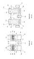
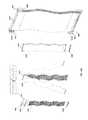
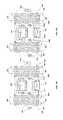
- FIG. 1Aillustrates a desiccant air handling system using a shower head design in accordance with the prior art.
- FIG. 1Billustrates a desiccant air handling system using a plate design and horizontal air flow in accordance with the prior art.
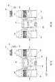
- FIG. 2Ashows a desiccant air handling system set up for extreme summer operation with cold source and PV/Thermal module tie-in in accordance with one or more embodiments.
- FIG. 2Bshows a desiccant air handling system set up for non-extreme summer operation with cold source and PV/Thermal module tie-in in accordance with one or more embodiments.
- FIG. 3Ashows a desiccant air handling system set up for extreme winter operation with cold source and PV/Thermal module tie-in in accordance with one or more embodiments.
- FIG. 3Bshows a desiccant air handling system set up for non-extreme winter operation with cold source and PV/Thermal module tie-in in accordance with one or more embodiments.
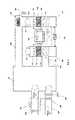
- FIG. 4shows the integration between a building's existing air conditioning system, a desiccant air conditioning system and PVT modules in accordance with one or more embodiments.
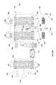
- FIG. 5shows a desiccant system employing a vertical air flow in accordance with one or more embodiments.
- FIG. 6Adepicts a three-dimensional view of the system of FIG. 5 in accordance with one or more embodiments.
- FIG. 6Bdepicts one or more turbulence plates that create air turbulence in the air entering a set of plate structures.
- FIG. 7shows the vertical air flow desiccant system with optional pre- and post air treatment coils and heat pump system in accordance with one or more embodiments.
- FIG. 8depicts details around the wavy plate structures in accordance with one or more embodiments.
- FIG. 9shows a possible construction for the wavy plate structures in accordance with one or more embodiments.
- FIG. 10Ashows an alternative method for wavy plate structure assembly, including the mounting of a membrane or wicking material in accordance with one or more embodiments.
- FIG. 10Bshows a cross section of two membranes with a hydrophilic wicking material sandwiched in between two hydrophobic membranes wherein the wicking material spreads a liquid uniformly between the two membranes in accordance with one or more embodiments.
- FIG. 10Cshows a cross section of a hydrophobic membrane, a hydrophilic wicking material and a (thermally conductive) support wall in accordance with one or more embodiments.
- FIG. 10Dshows a cross section of two membranes with two wicking materials and an internal (thermally conductive) support wall in accordance with one or more embodiments.
- FIG. 10Eshows a cross section of two membranes with two wicking materials and an internally hollow (thermally conductive) support wall in accordance with one or more embodiments.
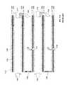
- FIG. 11Ashows how the plate structures can be stacked into larger arrays and depicts construction details in accordance with one or more embodiments.
- FIG. 11Billustrates desiccant system employing a horizontal air flow through two conditioners in accordance with one or more embodiments, wherein the air is treated twice by plates that are oriented at an angle to the air flow.
- FIG. 11Cshows a top view of the embodiment of FIG. 11B .
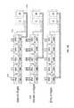
- FIG. 11Dshows the arrangement from FIG. 11B replicated twice in such a way as to treat the incoming air into a space and to recover energy from the returning air in a second set of conditioners in accordance with one or more embodiments.
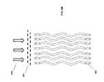
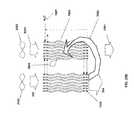
- FIG. 11Eshows a desiccant membrane plate stack in the prior art that uses a portion of the dehumidified air for indirect evaporative cooling in accordance with one or more embodiments.
- FIG. 11Fillustrates a section of a desiccant membrane plate stack that uses a portion of the dehumidified air to provide indirect evaporative cooling in a controllable fashion
- FIG. 11Gshows a close up cut away detail for the bottom of the plate stack in FIG. 11F .
- FIG. 11Hillustrates further details of some of the components shown in FIG. 11F .
- FIGS. 11I and 11Jshow a three dimensional and top view, respectively, of an embodiment that uses a tube structure for exposing liquid desiccant to air streams while providing a simultaneous heating or cooling functions in accordance with one or more embodiments.
- FIGS. 11K and 11Lillustrate a three dimensional and top view, respectively, of a hexagonal structure for exposing liquid desiccant to an air stream while providing heating or cooling functions in accordance with one or more embodiments.
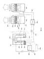
- FIG. 12depicts a complete solar air conditioning system including a solar PV/Thermal array in accordance with one or more embodiments.
- FIG. 13Ademonstrates how storage and PVT modules can be used to create a hot/cold offset cycle for a desiccant air conditioning system during the day in accordance with one or more embodiments.
- FIG. 13Bdemonstrates how storage and PVT modules can be used to create a hot/cold offset cycle for a desiccant air conditioning system during the night in accordance with one or more embodiments.
- FIGS. 14A and 14Bshow a PV/Thermal module with integrated hot water storage/ballasting system in accordance with one or more embodiments.
- FIGS. 15A and 15Bshow how the ballast tank and storage system can double as a shipping container for the PVT module in accordance with one or more embodiments.
- FIGS. 16A and 16Bdemonstrate how PVT modules and cold sources can be integrated into the wavy plate desiccant system for summer operation in accordance with one or more embodiments.
- FIGS. 17A and 17Bdemonstrate how PVT modules can be integrated into the wavy plate desiccant system and humidifiers for winter operation in accordance with one or more embodiments.
- FIGS. 18A and 18Bshow how the heat from storage or PVT modules can be used during the day and during the night for air conditioning operation in accordance with one or more embodiments.
- FIG. 19Ashows how a desiccant concentration separator and evaporative cooler can be integrated into the wavy plate system during summer operation in accordance with one or more embodiments.
- FIG. 19Bshows the system of FIG. 19A integrated to a building space wherein the chilled water that is produced by the evaporative cooler is not only used for cooling the conditioner but also used for cooling ceiling panels or floor panels.
- FIG. 20Ashows how the additional wavy plates in FIG. 19A can be used to increase heating capacity during winter operation in accordance with one or more embodiments.
- FIG. 20Bshows how a portion of the air entering a conditioner can be drawn out of the conditioner and diverted to a third set of wavy plates for winter operation.
- FIG. 21Ashows a corrosion resistant heat exchanger with thermally conductive plastic plates in accordance with one or more embodiments.
- FIG. 21Bshows a different embodiment of a corrosion resistant heat exchanger with thermally conductive plastic plates in accordance with one or more embodiments.
- FIG. 21Cshows the major manufacturing steps involved in using glue structures to construct a fluid to fluid heat exchanger in accordance with one or more embodiments.
- FIG. 22shows a water recovery system using plate structures in accordance with one or more embodiments.
- FIG. 23shows a desiccant system for heating and dehumidification in accordance with one or more embodiments.
- FIG. 24Ashows a heating and dehumidification system using the wavy plates and a water recovery system in accordance with one or more embodiments.
- FIG. 24Bshows a dual effect desiccant regeneration system which uses recovered liquid water for indirect evaporative cooling.
- FIG. 25shows a desiccant air conditioning system which captures and condenses combustion gasses and recovers water in accordance with one or more embodiments.
- FIG. 26shows a desiccant air conditioning system setup for winter heating that also condenses water vapor and captures contaminants from the combustion process in accordance with one or more embodiments.
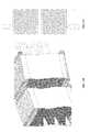
- FIGS. 27A and 27Bshow a three-dimensional model of the system of FIG. 24A in accordance with one or more embodiments.
- FIG. 28shows the water recovery system of FIG. 22 integrated to a desalination system for water purification in accordance with one or more embodiments.
- FIG. 1Adepicts a liquid desiccant air conditioning system as known in the prior art.
- a desiccant conditioner 102contains a liquid desiccant in a bath 104 .
- the liquid desiccant 104can be any suitable solution that attracts water vapor from the outdoor air 110 that is blown into the conditioner 102 .
- the airmoves through a filter media 106 that usually comprises a convoluted surface that easily holds and exposes the desiccant to the air stream. Examples of desiccants include CaCl 2 and LiCl 2 .
- the filter mediacan be a cellulosic cooling tower fill material. Diluted desiccant 105 that has absorbed water drips from the filter media 106 into the desiccant bath 104 .
- the spray head 107distributes the concentrated desiccant evenly across the filter media 106 .
- Dehumidified and cooled air 111is directed into the building.
- a portion (usually around 10%) of the diluted desiccant 112is brought through a heat exchanger 103 to a regenerator 101 .
- the majority of the desiccant 112is brought back to the spray head 107 at the top of the conditioner 102 through an optional cold source 113 .
- the desiccant that is diverted to the regenerator 101is heated in an optional heater 114 and pumped to a spray head 107 ′ similar to the spray head on the conditioner side.
- the heated desiccantfalls onto a filter media 106 ′ and drips down 105 ′ into a desiccant bath 104 ′.
- Return air from the building or outdoor air 108is brought through the filter media and absorbs water from the desiccant such that moist hot air 109 is exhausted from the regenerator.
- the drawbacks of this systemare that the absorption of water vapor into the desiccant is an almost adiabatic process resulting in heating of the air that is meant to be cooled.
- the spray headcan lead to some desiccant being carried over into the leaving air streams 111 and 109 .
- the baths 104 and 104 ′force the air flows 110 and 108 to be horizontal and vertical through the filter media. This makes installation on a building roof more complicated since the exiting air 111 needs to be ducted into a downward direction and the return air 108 from the building needs to be ducted into a horizontal aspect.
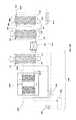
- FIG. 1Bis an alternate system known in the prior art.
- the conditioner 121comprises a set of vertical plates 118 (which are constructed to be hollow inside) and a desiccant collector 120 . Chilled heat transfer fluid from a cold source 113 is brought inside the plates 118 and forms a U-shaped loop 116 internal to the plate. A concentrated desiccant 119 is run over the surface of the plates 118 . Outdoor air 110 is directed over the desiccant 119 in a horizontal orientation. The desiccant absorbs water vapor from the air and runs down the surface of the plates 118 into the desiccant collector 120 . The diluted desiccant 121 is pumped through a heat exchanger 103 to the regenerator 122 .
- the regeneratorcomprises a set of plates 117 that again are hollow and that have U-shaped channels 116 ′ in them. Diluted desiccant 119 ′ is again run over the surface of the plates 117 that are heated by the hot transfer fluid source 114 . Outdoor air or return air from the building 108 is used to absorb water vapor from the desiccant 119 ′. The desiccant gets more concentrated as it runs down the surface of the regenerator and collects into the desiccant collector 115 . As in the previous example, the air flow in the desiccant system is primarily horizontal resulting in the need for additional ducts to be used for installation on a rooftop.
- the desiccant collectors 115 and 120generally block air from flowing vertically. Furthermore, the U-shaped channels do not allow for a counter-flow design between the air, desiccant, and cooling or heating fluids resulting in lower thermal efficiency of both the conditioner and the regenerator. As compared to the system in FIG. 1A , the liquid desiccant system in FIG. 1B uses lower fan power and lower desiccant pump power.
- FIG. 2Ashows a liquid desiccant system in accordance with one or more embodiments configured for extreme summer operation and so as to integrate with and optional heat pump 201 .
- a portion of the desiccant in the conditioner 102is brought through a heat exchanger 202 that can be coupled to a PVT module array. Since the typical desiccant materials that are used are corrosive to metals, the use of a heat exchanger is desirable. This also complicates the integration of the heat pump 201 ; since the desiccant should not contact any metal parts, the heat transfer is made indirectly through a specially designed heat exchanger.
- desiccantis taken from the conditioner, is heated in the PVT modules 202 or by the heat pump 201 and sprayed into the regenerator 101 .
- concentrated desiccantis taken from the regenerator 101 , run through an optional cold source 203 or through the cold side of the heat pump 201 and into the conditioner.
- FIG. 2Ba similar set up is shown for non-extreme operation.
- the main differenceis that the desiccant from the conditioner is cooled, and put back into the conditioner side rather than also being transported to the regenerator. Desiccant only transfers to the regenerator through the heat exchanger 103 . Similarly the desiccant in the regenerator is only heated and put back into the regenerator itself rather than being put into the conditioner.
- the heat sources 201 and 202are now heating the liquid desiccant as it is transported to the conditioner 102 .
- the conditioner in the winter setupis used to add water vapor and heat to in incoming air stream 110 and conditions the air to have a higher temperature and humidity as it enters the building at 111 .
- a humidifier 301that can be preheated by another PVT module array 302 or by another source of thermal energy. Since the water that is brought into the humidifier 301 is not corrosive to metals, it is not per-se necessary to use a heat exchanger in 302 ; the water can be heated directly by the PVT modules.
- the return air 108 from the buildinggenerally is higher in temperature and humidity than the outside air 110 .
- the regenerator 101 in this setupactually captures the heat and moisture from the return air and transports it to the outdoor air, resulting in much lower heating costs and the desiccant system is in this setup effectively functioning as an enthalpy recovery system.
- FIG. 3Ba similar setup is shown as in FIG. 3A , except now the heat sources 201 and 202 are now used to heat the desiccant on the conditioner 102 side of the system directly. Similarly the cold side of the heat pump 201 can directly draw heat from the desiccant in the regenerator.
- the cold source 203 in FIGS. 3A and 3Bwill in most cases not be needed during winter operation of the system. It is also noted that the desiccant in winter mode will need to be diluted which means that small amounts of water will need to be added on a regular basis in order to prevent overconcentration of the desiccant. This water can come from the return air from the building, but may still need to be supplemented from other sources.
- FIG. 4shows how the enthalpy recovery system from FIG. 3A can be integrated into an existing building air conditioner infrastructure.
- the building space 401is connected by ducts 402 to the desiccant system from FIG. 3A .
- the existing air conditioner heat pumpcomprising compressor 403 releases heat through fan coil 405 and the incoming air can be supplementally heated by PVT modules 406 and an additional fan coil.
- the compressed gasexpands at the valve 407 and is heated by the return air in fan coil 404 before returning to the compressor 403 .
- the above described setupsignificantly reduces the load on the air conditioning system by again recovering both heat and water vapor.
- the conditioner 501comprises a set of plate structures that are internally hollow.
- the plate structurescan have a wavy shape applied to them.
- the term wavy as used hereinrefers broadly to a variety of convoluted structures, including serpentine or undulating shapes.
- a cold heat transfer fluidis generated in cold source 507 and entered into the plates.
- Liquid desiccant solution at 514is brought onto the outer surface of the plates and runs down the outer surface of each of the plates. In some embodiments, the liquid desiccant runs in a wicking surface that significantly increases the area of desiccant exposed to the air stream 503 .
- the liquid desiccantruns behind a thin membrane that is located between the air flow and the surface of the plates.
- Outside air 503is now blown through the set of wavy plates.
- the liquid desiccant on the surface of the platesattracts the water vapor in the air flow and the cooling water inside the plates helps to inhibit the air temperature from rising.
- the plate structuresare constructed in such a fashion as to collect the desiccant near the bottom of each plate thereby eliminating the need for a desiccant collector or bath as was shown in FIGS. 1A and 1B .
- the treated air 504is now put in the building directly without the need for any additional ducts.
- the wavy shape of the plateshas two primary advantages: air is more easily brought in contact with the surface of the plates since the wavy shape constitutes more of a convoluted path than a straight plate would have given. But importantly, the wavy shape allows for the plates to expand sideways without putting undo stresses on the connections for heat transfer fluids and desiccants at the top and bottom of the plates. This is particularly important since the wavy plates should be constructed from a material that is compatible with the desiccant being used, for example from a (thermally conductive) plastic material such as a thermally doped polymer extrusion.
- such a plastichas a thermal conductance of about 5 to 10 W/mK.
- thermal conductances for regular plasticsrange from 0.1 to 0.5 W/mK
- copper, aluminum, stainless steel and titaniumhave a conductance of about 400, 250, 16 and 18 W/mK respectively.
- titaniumis reasonably suitable for use with desiccants such as CaCl 2 or LiCl 2 due to the corrosive nature of the desiccants.
- the wavy plates in the regenerator 502will expand under the higher temperatures for regenerating the desiccant. This can create thermal stresses on the assembly. The wavy shape helps to reduce those stresses by allowing the plates to expand sideways rather than in the vertical direction.
- the liquid desiccantis collected at the bottom of the wavy plates at 511 and is transported through a heat exchanger 513 to the top of the regenerator to point 515 where the liquid desiccant is distributed across the wavy plates of the regenerator.
- Return air or optionally outside air 505is blown across the regenerator plate and water vapor is transported from the liquid desiccant into the leaving air stream 506 .
- An optional heat source 508provides the driving force for the regeneration.
- the hot transfer fluid 510 from the heat sourcecan be put inside the wavy plates of the regenerator similar to the cold heat transfer fluid on the conditioner.
- the liquid desiccantis collected at the bottom of the wavy plates 502 without the need for either a collection pan or bath so that also on the regenerator the air can be vertical. It should be clear to those skilled in the art that the wavy plates can be easily expanded to add additional cooling or heating capacity, that these plates provide for better heat transfer and that the elimination of any bath or collection pan allows for the system to be directly mounted on a roof opening without the need for additional duct work.
- An optional heat pump 516can be used to provide cooling and heating of the liquid desiccant similar to the method employed in FIG. 1A . It will be clear to those skilled in the art that the absence of a liquid bath or collection pan also enables the easy installation of the conditioner 501 in a remote location from other components in the system, such as are commonly used in what is know as “split” air conditioning systems.
- the system of FIG. 5can be made relative small in size in such a way that the system could be integrated into an automobile or other vehicle.
- the heat source 508can potentially be the heat from an engine and cooling could be provided by a Peltier cooling system.
- FIG. 6Athe system of FIG. 5 is shown in a 3 dimensional projection.
- Desiccant fluid pumps 601provide the transportation of the desiccant between the conditioner and the regenerator.
- the holes 602 at the top of wavy plates 501 and 502ensure an even distribution of desiccant over the surface of the wavy plates.
- Groves 603 at the bottom of the wavy plates 501 and 502collect the desiccant by using either the natural surface adhesion of the desiccant to the plastic of the wavy plates to gather the desiccant into the grove or by using some membrane or other wetting material to help collect the desiccant into the groove.
- the heat transfer fluidcan be connected to the wavy plates at connections 604 , 605 , 606 and 607 .
- FIG. 6Bshows how the inlet air 652 of a set of wavy plates 502 can be made turbulent by a set of plates 651 .
- the plates 651are constructed in such a way as to impart turbulent airflow to the air entering the wavy plates 502 .
- the resulting turbulent airwill better exchange heat and moisture with the surface of the wavy plates as compared to air that flows through the wavy plates in laminar fashion.
- FIG. 7depicts the system similar to FIG. 5 with the addition of a post conditioner cooling coil 702 and preheating coil 701 for the regenerator.
- An alternate configuration for the heat pump 705is to instead of heating the desiccant as in FIG. 5 , to heat the heat transfer fluid with heat exchanger coils 703 and 704 .
- FIG. 8shows a close-up view of one embodiment of the wavy plate assembly where the desiccant drain 801 at the bottom of the plates collects the desiccant that has run into the groove 811 .
- Heat transfer fluidis connected to the plates at 802 and 805 .
- the main body of the wavy plates 803can be made from a suitable material that exhibits good thermal conductivity as well as corrosion resistance, for example a thermally conductive plastic extrusion.
- Liquid desiccantis entered into the distribution channel 806 at the top of the plates 807 and exits the holes 810 at the top of same plates and runs over the surface 804 .
- the heat transfer fluid 808runs inside openings 809 in the wavy plates.
- the construction of the grooves 811allows the desiccant to collect at the bottom of each individual plate without obstructing the air flow and without the need for a separate common collection pan. It should be obvious to those skilled in the art that the entering air stream 812 and exiting air stream 813 can be reversed and also that the direction of the heat transfer fluid between 802 and 805 can be either upwards or downwards.
- the desiccant itselfwould normally run down the surface because of the force of gravity acting on the desiccant.
- FIG. 9shows further details of one embodiment of the construction of such wavy plates.
- a component 901which is preferably an injection molded plastic component, is bonded on the thermally conductive extrusion 902 . It should be obvious to those skilled in the art that other manufacturing methods can be employed such as machining, thermoforming, welding and other suitable methods. Other materials for the components can be suitably selected to be compatible with the corrosive nature of typical desiccant solutions, for example Titanium and other noble materials.
- a similar component 903also preferably injection molded, is bonded to the top of component 902 . Desiccant is introduced through inlet 905 and spreads generally evenly through the holes 904 . Heat transfer fluid is transferred through the openings 905 and exists through the openings 907 . Desiccant that has run to the bottom of the wavy plates is collected by taking advantage of surface tension in the liquid into the groove 811 and runs through the drain exit 906 .
- FIG. 10Ashows an alternative embodiment of a wavy plate construction in which components 1001 and 1002 , which are preferably injection molded, are connected to the top of a wavy plate 1003 .
- Spreader plates 1013cause the desiccant and heat transfer fluid to be generally evenly distributed.
- an additional injection molded component 1004provides the collection of the heat transfer fluid inside the wavy plate 1003 .
- a membrane or other suitable materialsuch as a wicking material 1005 is applied over the top of the assembly.
- An example of such a membraneis hydrophobic Poly Propylene manufactured by Celgard under the tradename EZ2090.
- An example of a wicking surfaceis a hydrophilic cardboard sheet material similar to coffee filter paper.
- the completely mounted assembly 1007is then connected to a final injection molded component 1006 in such a way that the membrane or wicking material guides the desiccant into the component 1006 .
- the liquid channels for the desiccant 1009 and 1012are shown, as are the channels for the heat transfer fluid 1010 and 1011 .
- the material 1005comprises a membrane
- Holes 1014are purposely provided to allow air to enter behind the membrane so that the liquid desiccant can easily fill and drain behind the membrane.
- holesalso keep the membrane from accidentally getting pressurized, which could result in damage or deformation of the membrane.
- the holesare located slightly above the outlet of the desiccant as can be better seen in FIG. 11A . It can also be seen in 1008 that two wavy plate assemblies have been joined together to form a small stack of plates. It should be obvious to those skilled in the art that the assembly of wavy plates can so be stacked as to generate any amount of air treatment as desired by simply adding additional plates to the stack.
- FIG. 10Bshows a detailed cross section of two hydrophobic materials such as membranes 1051 with a hydrophilic wicking material 1052 .
- a hydrophilic wicking material 1052Since micro-porous membranes or similar materials are usually made to be hydrophobic, the application of a membrane can have non-uniform wetting caused by the liquid (such as—by way of example—a salt solution or water) to be repelled by the membrane. The repellent forces result in non-uniform flow of liquid on the back of the membrane.
- the wicking effect of the hydrophilic materialcauses the liquid to evenly distribute behind the membrane resulting in significantly increased evaporation through the membrane and a significantly increased active area. A liquid running inside the wicking material will spread uniformly between the two membranes.
- FIG. 10Cshows a hydrophilic material 1052 behind a hydrophobic material such as a membrane 1051 , attached to a thermally conductive support wall 1053 (which can be, e.g., a wavy plate).
- a hydrophobic materialsuch as a membrane 1051
- a thermally conductive support wall 1053which can be, e.g., a wavy plate.
- the support wallis also hydrophobic such as is often the case with plastics and the like, then the wicking material will ensure even flow distribution of the liquid.
- the support wallcan be made to be thermally conductive which would allow one to adjust the temperature of the liquid inside the wicking material and thereby control the evaporation of absorption through the membrane.
- FIG. 10Dshows a similar structure as in FIG. 10C wherein the wicking material is applied on both sides of the (thermally conductive) support wall 1053 .
- the liquids inside the wetting materials 1052 on each side of the wallcan now be made to be different.
- the leftmost wicking materialcould be wetted with a salt solution and the rightmost wicking material could be wetted with water or some other heat transfer fluid.
- FIG. 10Eshows a structure similar to FIG. 10D wherein the support wall 1053 is now made to be hollow such that a heat transfer liquid 1054 can be used inside the support wall.
- a structureallows heat transfer from the heat transfer fluid 1054 through the walls into the wicking materials 1052 on either side of the wall 1054 .
- hydrophobic and hydrophilic materialscan be devised.
- FIG. 11Adepicts additional details of the construction of such as stack of wavy plates.
- a stack of wavy plates 1101can be set up to treat air multiple times by stacking the plates vertically as well as horizontally. Vertical stacking allows air to be treated for instance to increase dehumidification, whereas horizontal stacking increases the overall capacity of treated air.
- Detail 1102shows a detail of the bottom of the wavy plate construction in which the membrane or wicking surface 1005 is used to guide the desiccant into the bottom drain 1006 .
- the lower edge 1111 of the membrane or wicking materialis not fixedly connected so as to avoid potential pressure buildup of desiccant which could lead to damage of the membrane or wicking surface.
- Detail 1107shows the same area as detail 1102 except with the membrane 1005 removed.
- the channels 1109 and 1110 that are created in the components 1004 , 1006 and 1003allow for the membrane 1005 to be bonded, but still allow for the desiccant to pass through the channels.
- detail 1103 of the top of the wavy plate assemblyshows how the desiccant is able to enter through supply channel 1012 and run through the channels in components 1002 and over the surface of wavy plate component 1003 .
- the holes 1014 and the unconnected edge 1111 at the bottomadvantageously serve the function to 1) inhibit vapor lock at the top of the assembly and 2) to avoid pressure damage to the membrane or wicking surface at either the top or the bottom of the assembly.
- detail 1108shows the same top assembly with the membrane 1005 removed.
- the surface area of the wavy plate assembly 1101is important for the overall air treatment capacity of the system, it should be easy to stack multiple wavy plates in both the horizontal and vertical direction as discussed above.
- Features 1104 , 1105 and 1106allow for stacking of plates by aligning and locking plates together. It should be clear to those skilled in the art that such features can have many shapes and sizes.
- FIG. 11Bshows a system setup similar to FIG. 5 wherein the wavy plates are accepting a horizontal air flow.
- the wavy platesform two stacks in such a way as to treat the air passing through twice.
- the airwill interact more readily with the liquid desiccant on the surface of the wavy plate.
- Such liquid desiccantcan be located behind a membrane or in a wetting material as described before.
- FIG. 11Cillustrates the setup from FIG. 11B in a top-down view.
- FIG. 11Dshows the dual set of wavy plates from FIG. 11B implemented twice.
- the first settreats air coming from outdoors and performs a double treatment of this incoming air.
- the second setreceives return air from a space and also treats it twice.
- the recovery of energywater vapor and thermal energy
- This setupallows for energy recovery while still allowing thermal energy to be added or removed and water to be added to air coming through the plate system through the desiccant, thereby enhancing the heating or cooling of the incoming air.
- Conventional energy recovery systemstypically do not allow for the addition or removal of thermal energy or water.
- FIG. 11Eillustrates a desiccant cooling system in the prior art.
- a stack of plates 1134is placed (typically about 0.25 inch apart) and is covered by a membrane 1131 that has water 1133 flowing behind it.
- the opposite site of the platecontains a second membrane 1135 behind which a liquid desiccant is flowing.
- Incoming air 1136is dehumidified because water vapor in the air is absorbed into the liquid desiccant through the membrane 1135 .
- the dehumidified air 1137is partially directed towards the space being cooled and a portion is directed in the reverse direction 1138 .
- This secondary air flow 1138is relatively dry and can effectively absorb water vapor from the water 1132 behind the membrane 1135 .
- FIG. 11Fillustrates an embodiment of the concept of FIG. 11E wherein wavy plates 1147 are used to provide and alternating structure for liquid desiccant and water.
- the wavy platesare made using thermally conductive plastics.
- the wavy platescontain ridges 1146 to support the membranes 1131 and 1135 .
- Liquid desiccantenters the wavy plate set through channel 1141 and exists through channel 1144 .
- Waterenters through channel 1142 and exits through channel 1143 .
- An adjustably connected air diverter 1145takes a controllable amount of air in directs it in the reverse direction 1138 .
- the diverted air 1138absorbs water from behind the membrane 1135 .
- the diverter 1139closes the top of the opening between the plates and directs the airflow 1140 in a perpendicular direction.
- the bottoms and tops of the wavy plates 1147are inserted into an injection molded component 1006 similar in design to FIG. 10A .
- FIG. 11Gshows a detail of FIG. 11F wherein a close-up of the wavy plates 1147 that have the membranes 1131 and 1135 mounted to the ridges 1146 on the wavy plates.
- holes 1150 and 1151are provided in such as way is to provide access to alternating sides of the wavy plates 1147 .
- the liquid desiccantenters the drain channel 1144 through the holes 1152 .
- the wavy plates 1147can be made to be generally identical, except that the wavy plates are flipped upside down in an alternating fashion.
- FIG. 11Hshows a detail of the wavy plates 1147 .
- the wavy platesare alternatively flipped upside down to provide opposing connections to the water and desiccant supply lines.
- the ridges 1146provide support for the membrane and the thermally conductive surface 1134 provides a thermally conductive path to the opposite side of the wavy plate.
- the holes 1153provide a uniform distribution of the liquids similar to the holes in component 1013 in FIG. 10A .
- FIGS. 11I and 11Jillustrate a tubular structure for exposing a liquid desiccant to an air stream through a membrane while simultaneously exposing the liquid desiccant to a heat transfer fluid.
- the structurecomprises a plurality of tubes 1181 that can be made from any suitable thermally conductive material for example from a thermally doped polymer extrusion.
- the inner wall of the tubecan feature ridges 1184 to allow a membrane 1182 to be bonded to the top of the ridges in such a way that the membrane is held at a small distance to the tube wall so that liquid desiccant can pass between the wall and the membrane perpendicular to the plane of the figure in the so created channel 1183 .
- Aircan thus be passed in the center of the tubes 1186 , while heat transfer liquid can pass in the generally triangular sections 1185 between tubes.
- the heat transfer fluidis thus able to heat the desiccant solution through the thermally conductive walls.
- FIGS. 11I and 11Jalso show that it would be possible to apply some wavy shape to the tube which as in the previous embodiment functions to achieve better interaction between air and desiccant while at the same time reducing stresses due to thermal expansion in the vertical direction of the structure.
- FIG. 11Lis a top view of an alternate hexagonal structure of thermally conductive surfaces 1192 in accordance with one or more embodiments.
- FIG. 11Kis a three-dimensional view of one of the hexagonal elements forming the hexagonal structure.
- Each hexagonal element in the structureincludes thermally conductive surfaces 1192 .
- Ridges 1194allow membranes 1191 to be mounted substantially parallel to the thermally conductive surfaces.
- the channels between the membrane 1191 and the walls 1192 in some of the elementscan be used for passage of a heat transfer liquid or alternately for passage of water to perform an evaporative cooling function in a similar manner to the system described in FIG. 11E .
- FIG. 11EIn the example shown in FIG.
- the hexagonal elements with channels between the membrane 1191 and the walls 1192 shaded in graycontain water, and the channels in the other hexagonal elements contain liquid desiccant.
- air in channels 1195can be exposed to the liquid desiccant through the membranes, while already treated air 1196 can be exposed to water through the membranes.
- FIG. 12shows how the wavy plate assemblies discussed above can be integrated into a full solar air conditioning system.
- the enclosure 1201provides protection of the desiccant air components from the weather.
- the systemincludes the conditioner 501 and the regenerator 502 .
- Pumps 601provide desiccant flow to the conditioner and regenerator.
- Blowers 1209move air into and out of the building.
- Outdoor air 503is treated by the wavy plates and moved into the building as treated air 504 .
- Return air 505 from the buildingcan absorb the heat and water vapor and is exhausted at 506 .
- a small optional chiller 1203provides sensible cooling if needed.
- a solar inverter 1202can invert the electricity coming from a series of solar modules 1205 .
- a supplemental water heater 1204that can be used when the PV-Thermal modules do not provide adequate temperatures or power.
- the solar modules 1205can have a water storage tank 1206 in such a way that access hot water can easily be stored.
- the hot water tank 1206is functions to provide ballast to the PVT module. Normally a concrete block or similar ballast would be provided to hold down solar modules on a flat roof.
- a thin flat tank like 1206we achieve two objectives: hot water storage as well as ballast.
- each solar modulecan have its own storage tank.
- FIG. 13Aillustrates how such a storage system as shown in the previous figure can be used.
- the PVT modules 1304start receiving solar radiation 1306 .
- the storage tanks 1305 underneath the PVT modulesare generally filled with cold water (or some other heat transfer fluid).
- the PVT modulesstart generating hot water which is directed to the solar air conditioning system 1200 , and specifically to the regenerator 1310 . Since sensible cooling also needs to be provided, one of the cold water tanks is connected to the conditioner 1309 .
- the PVT moduleswill generate excess hot water which can be used to start filling up some of the tanks
- the connection 1307 and 1308are made in such a way that the correct number of tanks is connected to the air conditioner 1200 .
- FIG. 14Ashows an embodiment of the solar PVT modules from FIG. 12 in some level of detail.
- the PV laminate 1401which can either be silicon or thin film based, generates the electrical power.
- the storage tank 1402doubles as a hot liquid storage container as well as a ballasting system.
- FIG. 14Bshows a cut-out close-up of the system.
- a series of thin channels 1405 behind the laminate 1401collect heat from the laminate and heats the transfer fluid.
- the main hot water channel 1404brings water down to a thermostatic valve assembly 1403 .
- the thermostatic valvecan direct hot water either directly to the main manifold 1406 or to the storage tank 1402 .
- the thermostatic valvecan either be operated automatically or through a software control.
- FIGS. 15A and 15Bdemonstrate another use of the storage tank underneath the PVT module.
- the storage tankis this case has a removable lid 1501 and a main body 1502 .
- the side and rear supports 1504 of the PV laminate 1503are removably connected to the tank and the PV laminate. After removing the lid 1501 , the entire solar module and support structure can be put inside the tank body thereby protecting the solar module during shipment.
- This alternate use of the tank as a shipping containercan be very helpful when solar modules have to be setup and disassembled on a regular basis for example as may occur for remote military basis. In effect, the tank now serves three functions: shipping container, storage tank and ballast system.
- FIG. 16Ademonstrates a schematic of the setup of a solar air conditioning integrated to a desiccant system for extreme summer operation. All of the desiccant from the conditioner 501 is sent to the regenerator 502 .
- the advantage of the plate structuresis that in effect the plate sets 501 and 502 are three way heat exchangers between air, liquid desiccant and a heat transfer fluid. This allows for PVT modules to be tied in at two places: directly heating the heat transfer fluid at 1601 , or heating the desiccant through a heat exchanger at 1602 . Similarly the cold connections for sensible cooling can either be made on the desiccant side 1604 or on the heat transfer fluid side 1603 .
- FIG. 16Bshows a setup for summer non-extreme operation.
- the major difference with the previous caseis that only a portion of the desiccant is send through the heat exchanger 513 .
- the flows of desiccant at 1609 and 1610can be adjusted so that only a portion of the desiccant is send to the regenerator.
- the PVT modulescan be tied in at two places: at the desiccant side 1606 and at the heat transfer fluid side 1605 . Again the cold connections can be made on either the desiccant 1608 or the heat transfer fluid 1607 . It will be clear to those skilled in the art that all the heat sources and cold sources can be supplemented by other sources tied into the same lines in parallel or in series to the PVT modules or cold sources in the drawings.
- FIG. 17Ashows a liquid desiccant system set up for winter heating in extreme conditions. Since active cooling of the leaving air is not necessary, the cold sources have been omitted from the drawings. Again PVT modules can be tied into desiccant side 1705 or the heat transfer fluid side 1706 . Since the heated desiccant will also emit water vapor additional water may have to be added at 1707 to prevent high concentrations of desiccant and potential crystallization of the desiccant salts. Furthermore the treated air 504 may require additional humidification 1703 which again can be done more efficiently by preheating the water at 1704 with PVT modules or another heat source.
- FIG. 17Bshows a similar setup to FIG. 17A except for non-extreme winter conditions whereby only a portion of the desiccant is send through the heat exchanger at 1708 and 1709 .
- FIG. 18Ashows how the PVT module array from FIG. 13A can be connected to the liquid desiccant system.
- PVT modules 1804receive heat and the hot heat transfer fluid is send to both the desiccant regenerator 502 and the hot storage system 1803 .
- the cold sidecan draw cold water from the cold storage tanks 1805 .
- FIG. 18Bshows how the regenerator is now drawing from the hot storage tanks 1803 whereas the conditioner is radiating heat through the PVT modules 1804 , which at the same tank provide cool water in the cold storage tanks 1805 .
- FIGS. 18A and 18Bworks well when there is a large temperature difference between night and day temperatures, e.g., as is the case in desert or in the central valley in California. However in other climates the temperature may not chance as much and additional sensible cooling can still be required. As discussed before such sensible cooling can be provided with a small chiller or a heat pump. It should be clear to those skilled in the art that other means of cooling such as Peltier cooling or evaporative cooling could be employed. In climates such as Miami, Fla. evaporative cooling is not as effective in the summer due to the already high humidity levels.
- FIG. 19Ashows an alternative method for cooling that uses a portion of the dehumidified air 504 and directs it to a third set of plate structures 1904 .
- the diverted air flow 1903is already treated and low in humidity.
- the third set of plate structureshas water running over its surface and behind a membrane or wicking surface, and has a heat transfer fluid internally to the plates 1907 .
- the diverted airis now directed between the wavy plates in effect creating what is known as an evaporative chiller using the wavy plates. Water is supplied to the third set of plate structures at 1905 and un-evaporated water is returned to the top of the plates through line 1909 .
- the portion of air 1903 that is divertedcan be adjusted with louvers or baffles or some other suitable mechanism in such a way that the amount of air is variable. Varying the amount of air will regulate the temperature achieved in the building by the entering air 504 .
- PVT modules 1807can be used at night to enhance the cooling effect and cold water can be stored in tanks 1805 . It would also be conceivable to locate the third set of plate structures 1904 (partially) underneath the conditioner 501 . This will increase the height of the overall stack, but negates the need to redirect the air 504 in the opposite direction. Conversely it would also be possible to divert the air 504 out of the plane of the drawing and into the third set of wavy plates in a horizontal flow pattern.
- Locating the third set of wavy plates underneath the conditioner plates 501has as a disadvantage that reversing the air flow for winter operation such as is shown in FIG. 20A becomes impossible.
- drawing a portion of the air 504 out perpendicular to the plane of the drawing and sending it through the third set of wavy plates 1904 in a horizontal fashionstill will allow the air in the third set of plates to be used for winter heating as is shown in FIG. 20B .
- FIG. 19Ashows another improvement to the desiccant system.
- Desiccant storage system 1902uses the fact that dilute desiccant will physically separate from concentrated desiccant if flow rates are low and the desiccant has sufficient time to settle. In other words if left alone the concentration in tank 1902 will tend to increase going from the top to the bottom.
- One can take advantage of this effectby connecting the desiccant lines at the appropriate heights along the sides of the tank.
- Onecan also draw the desiccant from a variable height in the tank using a vertically adjustable drain 1908 . By moving the drain 1908 up, the system will drawer lower concentration desiccant resulting in less dehumidification.
- FIG. 19Bshows the system of FIG. 19A wherein the third set of wavy plates 1904 that function to provide chilled water to the conditioner 501 are now also providing chilled water 1956 to one or more ceiling panels 1955 , a so-called “chilled ceiling”.
- This approachallows the chilled water produced in the third set of plates to also provide sensible space cooling in an integrated approach.
- the cooled and dried air 504 and 1952is typically guided through a series of ducts 1953 and delivered to the space 1954 in the building 1951 .
- This approachallows for easily balancing of the buildings requirements for latent and sensible cooling by varying the number of plates in the plate sets and by adjusting the desiccant concentration which in turn affects the humidity in the space.
- a series of fan coils or other suitable liquid to air heat exchangerscould be deployed.
- FIG. 20Ashows the system from FIG. 19A but set up for winter heating. Since oftentimes the heating capacity in the winter needs to be much larger than the cooling capacity in the summer, it is now possible to use the third set of wavy plates as part of the heating of the incoming air. Instead of flowing water over the surface of the third set of plates, the system is now using the liquid desiccant to treat the air.
- the supplemental heater 1901does not need to be used and neither does heat need to applied to the heat transfer fluid in loop 2001 .
- the supplemental heater 2003can be used to heat the heat transfer fluid in the conditioner wavy plate sets 501 and 1904 .
- Additional pre-heater coils 2006can be used to heat the entering air 503 and 1906 .
- the desiccant 2002 that enters the regenerator 502is picking up heat and water vapor from the leaving air 505 . As discussed for FIG. 17A , this serves to reduce the heating requirements for the conditioner as the desiccant through piping 2004 transports this heat and water to the conditioners. Lines 2005 now connect the desiccant to also reach the third set of wavy plates. As winter conditions oftentimes require humidification to occur, additional water can be added through either the same system 1905 that is used for evaporative cooling in summer mode or by additional humidifiers 1703 .
- FIG. 20Bshows how the air 2051 flows in substantially a vertical direction through the third set of plates 1904 during winter heating pushed by the fan 2053 .
- the air 504is directed out of the plane of the drawing following the arrow 2052 and directed into a substantially horizontal flow direction by the fan 2054 which is substantially located behind the plane of the drawing and behind the third set of wavy plates 1904 .
- the advantage of this approach over the approach described in FIG. 20Ais that there is no need for a reversible air fan: instead a winter fan 2503 is used during heating season and a summer fan 2504 is used during cooling season.
- the fan 2505 on the conditioneris always directing air in the same vertical flow.
- a further advantage of this approachbesides the increase in winter heating capacity is that the entire area of the third set of plates is actively used in both winter and summer.
- the approach described in FIG. 11Ehas as a disadvantage 1) that is not reversible for winter heating support, 2) that the effective area, particularly for the water channels 1138 is reduced due to the manner in which air flows through the evaporative channel 1138 , and 3) that the ratio of evaporative channels 1138 over desiccant channels 1137 is fixed, giving less flexibility to adopt the system to climates where maybe less evaporation is needed (sensible cooling) and more dehumidification (latent cooling).
- the flexibilityis increased to adopt the system to various climate conditions.
- FIG. 21Adepicts a plate heat exchanger in accordance with one or more embodiments. Since the desiccants used in these air conditioning systems are typically corrosive to metals, normal heat exchanger—which is typically constructed with metal—can not easily be used unless materials have been selected specifically for corrosive duty, which usually has a negative impact on cost. By using a flat plate construction wherein the entire units is made out of plastics, costs can typically be reduced. Desiccant enters the heat exchanger in two places, for example, hot desiccant enters at 2101 and exits as cold desiccant at 2103 , and cold desiccant enters at 2102 and leaves as hot desiccant at 2104 .
- the housing 2105contains a plate 2106 assembly that has thermally conductive surfaces 2110 .
- Obstructions 2109 inside the plates 2106create a long convoluted path for the desiccant.
- Vertical separators 2107create a long convoluted path for the fluid flowing in the opposite direction to the fluid inside the plates. Cutouts 2108 in the vertical separators 2107 force the opposing fluid into an up-down and left-right direction. It will be clear to those skilled in the art that other construction approaches of thermally conductive flat plastic plates can be used as a heat exchanger.
- FIG. 21Bshows an alternative arrangement of thermally conductive plastic plates for a heat exchanger.
- the heat exchanger 2150comprises a stack of formed, thermally conductive plastic plates 2155 and 2157 .
- Cold liquidenters at 2151 and is heated through the plate assembly and exits as hot liquid at 2152 .
- Hot liquidenters at 2153 and exits cold at 2154 .
- Each of the platescontains a seal 2156 that is oriented in such a way the even plates 2155 allow for flow from lower left to upper right of the plates 2155 and odd numbered plates 2157 have a mirror image seal 2156 ′ that allows flow from the lower right to the upper left.
- the turbulence ridges 2158cause the liquid flow to go up and down when it moves from the inlet to the outlet, thereby creating better heat exchange with the liquid in the next channel.
- the turbulence ridgescan be created by forming them into the plastic plate 2155 and 2157 such as for example by thermoforming or casting the plastic.
- a glue systemto attached glue lines 2158 to the plates 2155 and 2157 .
- glue linescan be formed by a simple XY robotic gluing system for example using 3M Corporation's Marine 5200 Polyurethane glue.
- the sealant lines 2156 and 2156 ′can also be formed using the same gluing system, except that the height of the sealant lines would be made about 2 ⁇ the height of the turbulence lines 2155 and 2157 , in such as way as that when the plates are stacked the glue lines support each other and the seal lines cover the distance between the top and bottom plates.
- FIG. 21Cis a cross section schematic view of the plate structure and exemplary manufacturing steps involved in using glue structures to construct a fluid to fluid heat exchanger as was shown in FIG. 21B .
- a plate 2155preferably made from a thermally conductive, non-corrosive material is first placed in a machine that can evenly apply glue ridges 2158 in a pre-determined pattern on one side of the plate. After the glue ridges are cured (step B), the plate is flipped over and a second set of glue ridges 2158 is applied to the opposite side of the plate (step C), in a similar or different pattern. A number of similar plates are thus constructed in this fashion.
- a base 2161 of the heat exchangeris positioned and a glue pattern 2156 meant for sealing to the base is applied.
- the first plate 2155is placed on the seal in such a way as to adhere to the underside of the first plate (step E).
- This process stepis repeated with the other plates (step F).
- the top plate 2162is placed with a glue seal 2156 ′ (step G).
- FIG. 22shows an arrangement whereby two sets wavy plates have been integrated into an enclosure 2201 .
- a first wavy plate set 2202has—as before—a hot heat transfer liquid generated by a heat source 2211 .
- Desiccant from a source 2203is directed to the surface of the wavy plates 2201 .
- the heat from the source 2203causes water vapor to evolve from desiccant on the surface of the wavy plates.
- Air 2205that is driven between the plates by the fan 2206 absorbs the water vapor and is moved to the right side of the system.
- the relative humidity in the enclosure 2201will reach close to 100%.
- the heated, moist air 2205exits from the first set of wavy plates, it will be close to saturation.
- the cold water loop 2208causes the water vapor to condense on the surface of the wavy plates 2207 and is then collected at the bottom of the wavy plates 2207 in the form of liquid water that flows out of the system at 2210 .
- the cooler air 2204exits the bottom of the wavy plates 2207 and is transported back to the first set of wavy plates 2202 , where it is heated again and where it absorbs water vapor from the desiccant, which starts the cycle over again. It is possible to add a vacuum pump 2209 so as to operate the system of FIG. 22 at reduced pressure. This would lower the required temperature to evolve water vapor from the desiccant on the first wavy plate set 2202 , but would make the system more complicated, for example one would also have to add a pump mechanism to retrieve the condensed water from the system at outlet 2210 and to prevent the backflow of the desiccant on the first set of wavy plates 2202 .
- An optional air to air heat exchanger 2212could be added, but that could lead to condensation in the heat exchanger, which would be more difficult to recover. It should be clear to those skilled in the art that the condensation in the wavy plates 2207 could be accomplished in other was such as a set of metal plates that are relatively cool as compared to the wavy plates 2202 . Since there is no desiccant involved in the condensation process, any suitable material such as metal plates can be used for the condensing component.
- FIG. 23shows a system that uses a liquid desiccant for the dehumidification of greenhouses.
- Conditioners 2322 and 2323contain liquid desiccant conditioners as shown also in FIGS. 1A and 1B .
- the spray heads 2314spray desiccant into a cooling tower fill 2315 , which dehumidifies the greenhouse air 2317 .
- Diluted desiccant 2316rains down into a collection bath 2318 .
- Some of the desiccant 2324is pumped through the heat exchanger 2320 and reaches a regenerator 2301 .
- the desiccantcan be optionally heated by a PVT module heat source 2319 before reaching the desiccant collector 2304 that is part of the regenerator.
- Some of the concentrated desiccant in the collector 2304is pumped to a heat exchanger 2306 and/or through an optional PVT module heating system 2305 before being sprayed into a filter material 2303 .
- the filter material 2303is able to spread the desiccant over a large area while letting air through.
- Air 2302is pumped by the fan 2309 through the filter material and picks up water vapor from the hot desiccant.
- the hot moist airis then transported to the other side of the regenerator where cold water is sprayed into the air at 2321 . Water condenses from the air and collects into a collection bath 2310 .
- Some of the wateris pumped through lines 2312 to heat exchangers 2313 where the water is cooled by the air stream coming through the conditioners 2322 and 2323 . Excess water is drained at 2311 .
- the heat for the systemis provided by water heater 2308 or optionally by the PVT modules 2307 .
- the heat exchanger 2306is needed because the corrosion of the desiccant does not allow direct heating by the water heater.
- FIG. 24Ashows a significantly more efficient water generation system.
- the wavy plate conditioner 2405treats the entering air 2406 and absorbs moisture as before into a desiccant running over the surface of the wavy plates.
- the leaving air 2407is warmer and dryer than the entering air 2406 .
- Diluted desiccantis pumped through a heat exchanger 2404 and through an optional PVT module heater 2403 to the water recovery system 2200 discussed above. Since the wavy plates in effect comprise a three way heat exchanger, the system 2400 can be much simpler.
- Water heater 2402 and optional PVT modules 2401heat a heat transfer fluid 2409 which runs through the wavy plates inside the water recovery system 2200 without the need for a heat exchanger.
- cooling liquid in 2408can run directly through the conditioner wavy plates 2405 without an additional heat exchanger.
- This simpler systemis also more energy efficient since the air flow in the conditioner is less obstructed and since the heating and cooling in the wavy plates is done in-situ. As a result a lower temperature heat source such as the PVT modules can be used. Water is recovered again at 2410 .
- FIG. 24Bshows a combination of the water recovery system from FIG. 22 and the indirect cooling system of FIG. 19A .
- the dilute desiccant 511is first directed to the plates inside the water recovery system 2200 .
- hot water 2409is provided to evaporate water from the liquid desiccant.
- the liquid desiccantexits at the water generator at higher concentration and is directed to the plates at 515 .
- Hot water vapor inside the water generator 2200heats the water loop 2408 which in turn heats the wavy plates 502 of the regenerator.
- Concentrated desiccant 512is then returned through the heat exchanger 513 to be reused in the conditioner.
- One advantage of this systemis that it can regenerate at higher efficiencies than a single effect regenerator, while still operating at lower temperatures.
- the recovered water 2410can be directed through water line 2451 and optional cooler 2452 to the evaporative section of the indirect cooling system from FIG. 19A , thereby reducing or even eliminating the need to provide a water supply source.
- FIG. 25shows the system of FIG. 24A with some additional improvements.
- the separator 2501Rather than sending all of the desiccant to the regenerator 2200 , the separator 2501 allows for the least concentrated desiccant near the top of the separator to be sent for regeneration and the most concentrated desiccant to be used again in the conditioner. Combustion of fossil fuels generally results in carbon dioxide and water vapor being produced. Other combustion byproducts are contaminants such as NO x and SO x and other residual by products. Gas burner 2502 produces these gasses if it is used in the space to be treated such as inside a greenhouse. Hot water coils 2503 absorb most of the heat generated by the burner. The hot water is used in the regenerator 2200 .
- Water vapor, CO2 and the contaminants such as NO x and SO xgo through the hot water coils and enter the wavy plates 2405 .
- the CO2is desired in the greenhouse, but water vapor and other contaminants are not.
- the wavy platesfunction as what is known as a condensing boiler by absorbing the water in the combustion exhaust, which releases additional heat and makes the overall combustion process more efficient.
- the desiccantis also able to absorb some of the contamination in the burner effluents.
- the desiccanttransports these contaminants with the water to the regenerator 2200 where supplemental filters 2411 can be employed to filter these contaminants out of the desiccant or out of the air stream in the regenerator.
- the arrangement in FIG. 25allows for burning of fuels such as biogases that are not as clean burning as natural gas.
- an additional external cooling cool 2504that can be added to aid in the condensation of the water.
- FIG. 26shows how some of the concepts discussed in the previous figure can also be integrated into winter heating system as discussed in FIG. 17 .
- Water heater 2602uses a gas burner 2601 .
- the heated water 2604can also be heated by the PVT modules 1706 to heat the conditioner 501 .
- Desiccant on the surface of the regenerator 501absorbs water vapor and other contaminants such as NO x and SO x and other residual by products.
- the desiccantis transported to the water recovery system 2200 through optional filters 2603 that can capture some of the contaminants in the desiccant.
- Recovered water at 2608can be drained off or can be diverted to a humidifier 1703 through lines 2609 , which can optionally be preheated by PVT modules 1704 or some other heat source.
- the cold loop for the condensation of water in the regenerator 2200can be cooled by an external cooling coil 2607 , but can also be cooled by running water to the wavy plates 502 by the lines 2606 .
- FIGS. 27A and 27Bshow three dimensional views of the desiccant system from FIG. 24A set up for greenhouse heating.
- FIG. 27Ashows the enclosure 2701 containing the desiccant conditioner wavy plates 2405 .
- Fans 2701can move the air through the desiccant conditioner.
- FIG. 27Bshows a rear view of the same system with some openings provided to illustrate the internal components.
- the regenerator plates 2202receive hot water from the water heater 2402 .
- Heat exchanger 2404separates the hot and cold desiccants.
- Condenser plates 2207collect the water from the system.
- FIG. 28shows how the water generator 2200 can be used in a desalination system.
- Seawater 2803is guided between a set of membranes 2801 that have concentrated desiccant 2804 on the opposite side.
- the desiccantfunctions as a draw fluid attracting water 2802 through the membrane into the desiccant, thereby diluting the desiccant.
- An optional set of PVT modules 2806can preheat some of the desiccant.
- the diluted desiccantis now guided through the heat exchanger 2811 to the regenerator 2200 .
- a heating system 2807heats a heat transfer fluid that is used in the regenerator wavy plates 2813 .
- the heat transfer fluidcan also be heated by the PVT modules 2812 .
- the desiccantcan also be heated by the PVT modules 2810 .
- An external cooling loop 2808can be employed to cool the condenser plates 2814 . Pure water is recovered at point 2809 .
Landscapes
- Engineering & Computer Science (AREA)
- Chemical & Material Sciences (AREA)
- Mechanical Engineering (AREA)
- General Engineering & Computer Science (AREA)
- General Chemical & Material Sciences (AREA)
- Chemical Kinetics & Catalysis (AREA)
- Oil, Petroleum & Natural Gas (AREA)
- Analytical Chemistry (AREA)
- Physics & Mathematics (AREA)
- Thermal Sciences (AREA)
- Combustion & Propulsion (AREA)
- Central Air Conditioning (AREA)
- Drying Of Gases (AREA)
Abstract
Description
Claims (50)
Priority Applications (4)
| Application Number | Priority Date | Filing Date | Title |
|---|---|---|---|
| US13/115,776US9429332B2 (en) | 2010-05-25 | 2011-05-25 | Desiccant air conditioning methods and systems using evaporative chiller |
| US15/177,755US10168056B2 (en) | 2010-05-25 | 2016-06-09 | Desiccant air conditioning methods and systems using evaporative chiller |
| US16/189,518US10753624B2 (en) | 2010-05-25 | 2018-11-13 | Desiccant air conditioning methods and systems using evaporative chiller |
| US17/002,371US11624517B2 (en) | 2010-05-25 | 2020-08-25 | Liquid desiccant air conditioning systems and methods |
Applications Claiming Priority (3)
| Application Number | Priority Date | Filing Date | Title |
|---|---|---|---|
| US34807610P | 2010-05-25 | 2010-05-25 | |
| US201161430692P | 2011-01-07 | 2011-01-07 | |
| US13/115,776US9429332B2 (en) | 2010-05-25 | 2011-05-25 | Desiccant air conditioning methods and systems using evaporative chiller |
Related Child Applications (1)
| Application Number | Title | Priority Date | Filing Date |
|---|---|---|---|
| US15/177,755DivisionUS10168056B2 (en) | 2010-05-25 | 2016-06-09 | Desiccant air conditioning methods and systems using evaporative chiller |
Publications (2)
| Publication Number | Publication Date |
|---|---|
| US20120125021A1 US20120125021A1 (en) | 2012-05-24 |
| US9429332B2true US9429332B2 (en) | 2016-08-30 |
Family
ID=45004771
Family Applications (18)
| Application Number | Title | Priority Date | Filing Date |
|---|---|---|---|
| US13/115,669Expired - Fee RelatedUS9000289B2 (en) | 2010-05-25 | 2011-05-25 | Photovoltaic-thermal (PVT) module with storage tank and associated methods |
| US13/115,665AbandonedUS20120186281A1 (en) | 2010-05-25 | 2011-05-25 | Methods and systems for desiccant air conditioning using fluids heated or cooled by a solar thermal system |
| US13/115,745Active2032-06-19US9243810B2 (en) | 2010-05-25 | 2011-05-25 | Methods and systems for desiccant air conditioning |
| US13/115,800Expired - Fee RelatedUS8943850B2 (en) | 2010-05-25 | 2011-05-25 | Desalination methods and systems |
| US13/115,753AbandonedUS20120125581A1 (en) | 2010-05-25 | 2011-05-25 | Heat exchanger and associated methods |
| US13/115,776Active2032-12-16US9429332B2 (en) | 2010-05-25 | 2011-05-25 | Desiccant air conditioning methods and systems using evaporative chiller |
| US13/115,736AbandonedUS20120125020A1 (en) | 2010-05-25 | 2011-05-25 | Methods and systems for desiccant air conditioning using photovoltaic-thermal (pvt) modules |
| US13/115,686Active2032-09-17US9273877B2 (en) | 2010-05-25 | 2011-05-25 | Methods and systems for desiccant air conditioning |
| US13/115,797Expired - Fee RelatedUS8800308B2 (en) | 2010-05-25 | 2011-05-25 | Methods and systems for desiccant air conditioning with combustion contaminant filtering |
| US13/115,783Expired - Fee RelatedUS9377207B2 (en) | 2010-05-25 | 2011-05-25 | Water recovery methods and systems |
| US13/115,760AbandonedUS20120131938A1 (en) | 2010-05-25 | 2011-05-25 | Air conditioning system with integrated solar inverter |
| US13/115,789Expired - Fee RelatedUS9086223B2 (en) | 2010-05-25 | 2011-05-25 | Methods and systems for desiccant air conditioning |
| US14/645,760Expired - Fee RelatedUS10006648B2 (en) | 2010-05-25 | 2015-03-12 | Methods and systems for desiccant air conditioning |
| US14/843,334ActiveUS9709286B2 (en) | 2010-05-25 | 2015-09-02 | Methods and systems for desiccant air conditioning |
| US14/869,504ActiveUS9631823B2 (en) | 2010-05-25 | 2015-09-29 | Methods and systems for desiccant air conditioning |
| US15/177,755Active2032-01-24US10168056B2 (en) | 2010-05-25 | 2016-06-09 | Desiccant air conditioning methods and systems using evaporative chiller |
| US16/189,518Active2031-06-17US10753624B2 (en) | 2010-05-25 | 2018-11-13 | Desiccant air conditioning methods and systems using evaporative chiller |
| US17/002,371Active2031-10-06US11624517B2 (en) | 2010-05-25 | 2020-08-25 | Liquid desiccant air conditioning systems and methods |
Family Applications Before (5)
| Application Number | Title | Priority Date | Filing Date |
|---|---|---|---|
| US13/115,669Expired - Fee RelatedUS9000289B2 (en) | 2010-05-25 | 2011-05-25 | Photovoltaic-thermal (PVT) module with storage tank and associated methods |
| US13/115,665AbandonedUS20120186281A1 (en) | 2010-05-25 | 2011-05-25 | Methods and systems for desiccant air conditioning using fluids heated or cooled by a solar thermal system |
| US13/115,745Active2032-06-19US9243810B2 (en) | 2010-05-25 | 2011-05-25 | Methods and systems for desiccant air conditioning |
| US13/115,800Expired - Fee RelatedUS8943850B2 (en) | 2010-05-25 | 2011-05-25 | Desalination methods and systems |
| US13/115,753AbandonedUS20120125581A1 (en) | 2010-05-25 | 2011-05-25 | Heat exchanger and associated methods |
Family Applications After (12)
| Application Number | Title | Priority Date | Filing Date |
|---|---|---|---|
| US13/115,736AbandonedUS20120125020A1 (en) | 2010-05-25 | 2011-05-25 | Methods and systems for desiccant air conditioning using photovoltaic-thermal (pvt) modules |
| US13/115,686Active2032-09-17US9273877B2 (en) | 2010-05-25 | 2011-05-25 | Methods and systems for desiccant air conditioning |
| US13/115,797Expired - Fee RelatedUS8800308B2 (en) | 2010-05-25 | 2011-05-25 | Methods and systems for desiccant air conditioning with combustion contaminant filtering |
| US13/115,783Expired - Fee RelatedUS9377207B2 (en) | 2010-05-25 | 2011-05-25 | Water recovery methods and systems |
| US13/115,760AbandonedUS20120131938A1 (en) | 2010-05-25 | 2011-05-25 | Air conditioning system with integrated solar inverter |
| US13/115,789Expired - Fee RelatedUS9086223B2 (en) | 2010-05-25 | 2011-05-25 | Methods and systems for desiccant air conditioning |
| US14/645,760Expired - Fee RelatedUS10006648B2 (en) | 2010-05-25 | 2015-03-12 | Methods and systems for desiccant air conditioning |
| US14/843,334ActiveUS9709286B2 (en) | 2010-05-25 | 2015-09-02 | Methods and systems for desiccant air conditioning |
| US14/869,504ActiveUS9631823B2 (en) | 2010-05-25 | 2015-09-29 | Methods and systems for desiccant air conditioning |
| US15/177,755Active2032-01-24US10168056B2 (en) | 2010-05-25 | 2016-06-09 | Desiccant air conditioning methods and systems using evaporative chiller |
| US16/189,518Active2031-06-17US10753624B2 (en) | 2010-05-25 | 2018-11-13 | Desiccant air conditioning methods and systems using evaporative chiller |
| US17/002,371Active2031-10-06US11624517B2 (en) | 2010-05-25 | 2020-08-25 | Liquid desiccant air conditioning systems and methods |
Country Status (7)
| Country | Link |
|---|---|
| US (18) | US9000289B2 (en) |
| EP (2) | EP2577178B1 (en) |
| JP (2) | JP5911850B2 (en) |
| KR (2) | KR102107636B1 (en) |
| CN (3) | CN110220254A (en) |
| ES (1) | ES2752069T3 (en) |
| WO (1) | WO2011150081A2 (en) |
Cited By (34)
| Publication number | Priority date | Publication date | Assignee | Title |
|---|---|---|---|---|
| US9810439B2 (en) | 2011-09-02 | 2017-11-07 | Nortek Air Solutions Canada, Inc. | Energy exchange system for conditioning air in an enclosed structure |
| US9816760B2 (en) | 2012-08-24 | 2017-11-14 | Nortek Air Solutions Canada, Inc. | Liquid panel assembly |
| US9909768B2 (en) | 2013-03-13 | 2018-03-06 | Nortek Air Solutions Canada, Inc. | Variable desiccant control energy exchange system and method |
| US9920960B2 (en) | 2011-01-19 | 2018-03-20 | Nortek Air Solutions Canada, Inc. | Heat pump system having a pre-processing module |
| US10302317B2 (en) | 2010-06-24 | 2019-05-28 | Nortek Air Solutions Canada, Inc. | Liquid-to-air membrane energy exchanger |
| US10323867B2 (en) | 2014-03-20 | 2019-06-18 | 7Ac Technologies, Inc. | Rooftop liquid desiccant systems and methods |
| US10352628B2 (en) | 2013-03-14 | 2019-07-16 | Nortek Air Solutions Canada, Inc. | Membrane-integrated energy exchange assembly |
| US10443868B2 (en) | 2012-06-11 | 2019-10-15 | 7Ac Technologies, Inc. | Methods and systems for turbulent, corrosion resistant heat exchangers |
| WO2019197975A1 (en) | 2018-04-09 | 2019-10-17 | Kiss Zoltan J | Air solar heating with integrated co2 from air absorption system |
| US10584884B2 (en) | 2013-03-15 | 2020-03-10 | Nortek Air Solutions Canada, Inc. | Control system and method for a liquid desiccant air delivery system |
| US10619867B2 (en) | 2013-03-14 | 2020-04-14 | 7Ac Technologies, Inc. | Methods and systems for mini-split liquid desiccant air conditioning |
| US10619868B2 (en) | 2013-06-12 | 2020-04-14 | 7Ac Technologies, Inc. | In-ceiling liquid desiccant air conditioning system |
| US10634392B2 (en) | 2013-03-13 | 2020-04-28 | Nortek Air Solutions Canada, Inc. | Heat pump defrosting system and method |
| US10712024B2 (en) | 2014-08-19 | 2020-07-14 | Nortek Air Solutions Canada, Inc. | Liquid to air membrane energy exchangers |
| US10731876B2 (en) | 2014-11-21 | 2020-08-04 | 7Ac Technologies, Inc. | Methods and systems for mini-split liquid desiccant air conditioning |
| US10753624B2 (en) | 2010-05-25 | 2020-08-25 | 7Ac Technologies, Inc. | Desiccant air conditioning methods and systems using evaporative chiller |
| US10760830B2 (en) | 2013-03-01 | 2020-09-01 | 7Ac Technologies, Inc. | Desiccant air conditioning methods and systems |
| US10782045B2 (en) | 2015-05-15 | 2020-09-22 | Nortek Air Solutions Canada, Inc. | Systems and methods for managing conditions in enclosed space |
| US10808951B2 (en) | 2015-05-15 | 2020-10-20 | Nortek Air Solutions Canada, Inc. | Systems and methods for providing cooling to a heat load |
| US10921001B2 (en) | 2017-11-01 | 2021-02-16 | 7Ac Technologies, Inc. | Methods and apparatus for uniform distribution of liquid desiccant in membrane modules in liquid desiccant air-conditioning systems |
| US10941948B2 (en) | 2017-11-01 | 2021-03-09 | 7Ac Technologies, Inc. | Tank system for liquid desiccant air conditioning system |
| US10962252B2 (en) | 2015-06-26 | 2021-03-30 | Nortek Air Solutions Canada, Inc. | Three-fluid liquid to air membrane energy exchanger |
| US11022330B2 (en) | 2018-05-18 | 2021-06-01 | Emerson Climate Technologies, Inc. | Three-way heat exchangers for liquid desiccant air-conditioning systems and methods of manufacture |
| US11092349B2 (en) | 2015-05-15 | 2021-08-17 | Nortek Air Solutions Canada, Inc. | Systems and methods for providing cooling to a heat load |
| US11333412B2 (en) | 2019-03-07 | 2022-05-17 | Emerson Climate Technologies, Inc. | Climate-control system with absorption chiller |
| US11385000B2 (en) | 2020-09-25 | 2022-07-12 | Emerson Climate Technologies, Inc. | Systems and methods for a non-pressurized closed loop water sub-system |
| US11408681B2 (en) | 2013-03-15 | 2022-08-09 | Nortek Air Solations Canada, Iac. | Evaporative cooling system with liquid-to-air membrane energy exchanger |
| US11512858B2 (en)* | 2017-10-31 | 2022-11-29 | Sharp Kabushiki Kaisha | Air conditioning apparatus and air conditioning method |
| EP4021615A4 (en)* | 2019-08-30 | 2023-10-04 | Eidon, LLC | REFRIGERATOR SYSTEM |
| US11892193B2 (en) | 2017-04-18 | 2024-02-06 | Nortek Air Solutions Canada, Inc. | Desiccant enhanced evaporative cooling systems and methods |
| US12066212B2 (en) | 2020-09-25 | 2024-08-20 | Copeland Lp | Systems and methods for a refrigerant sub-system for a heating, ventilation, and air conditioning system |
| US12385654B2 (en) | 2017-04-18 | 2025-08-12 | Nortek Air Solutions Canada, Inc. | Systems and methods for managing conditions in enclosed space |
| US12398907B2 (en) | 2020-12-08 | 2025-08-26 | Samsung Electronics Co., Ltd. | Ventilation system, integrated air conditioning system and control method thereof |
| US12442558B2 (en) | 2023-09-29 | 2025-10-14 | Nortek Air Solutions Canada, Inc. | Using liquid to air membrane energy exchanger for liquid cooling |
Families Citing this family (124)
| Publication number | Priority date | Publication date | Assignee | Title |
|---|---|---|---|---|
| JP5248629B2 (en) | 2008-01-25 | 2013-07-31 | アライアンス フォー サステイナブル エナジー リミテッド ライアビリティ カンパニー | Indirect evaporative cooler using liquid desiccant contained in membrane for dehumidification |
| US10274210B2 (en) | 2010-08-27 | 2019-04-30 | Nortek Air Solutions Canada, Inc. | Heat pump humidifier and dehumidifier system and method |
| US9885486B2 (en) | 2010-08-27 | 2018-02-06 | Nortek Air Solutions Canada, Inc. | Heat pump humidifier and dehumidifier system and method |
| US20120279567A1 (en)* | 2011-02-18 | 2012-11-08 | Ideal Power Converters Inc. | Solar Energy System with Automatic Dehumidification of Electronics |
| US9178466B2 (en)* | 2012-02-03 | 2015-11-03 | International Business Machines Corporation | Transportable photovoltaic system |
| ES2593111T3 (en)* | 2012-02-21 | 2016-12-05 | Watergy Gmbh | System for temperature regulation in closed spaces |
| US8726682B1 (en)* | 2012-03-20 | 2014-05-20 | Gaylord Olson | Hybrid multi-mode heat pump system |
| US9976822B2 (en) | 2012-03-22 | 2018-05-22 | Nortek Air Solutions Canada, Inc. | System and method for conditioning air in an enclosed structure |
| US20140054004A1 (en)* | 2012-08-24 | 2014-02-27 | Venmar Ces, Inc. | Membrane support assembly for an energy exchanger |
| NL2009415C2 (en)* | 2012-09-04 | 2014-03-05 | Aquaver B V | Air-conditioning system and use thereof. |
| US9731245B2 (en) | 2012-09-26 | 2017-08-15 | Dow Corning Corporation | Method of separating a gas using at least one membrane in contact with an organosilicon fluid |
| WO2014089164A1 (en) | 2012-12-04 | 2014-06-12 | 7Ac Technologies, Inc. | Methods and systems for cooling buildings with large heat loads using desiccant chillers |
| US10041692B2 (en) | 2013-02-26 | 2018-08-07 | Carrier Corporation | Regeneration air mixing for a membrane based hygroscopic material dehumidification system |
| US9267696B2 (en)* | 2013-03-04 | 2016-02-23 | Carrier Corporation | Integrated membrane dehumidification system |
| US9140471B2 (en) | 2013-03-13 | 2015-09-22 | Alliance For Sustainable Energy, Llc | Indirect evaporative coolers with enhanced heat transfer |
| US9140460B2 (en) | 2013-03-13 | 2015-09-22 | Alliance For Sustainable Energy, Llc | Control methods and systems for indirect evaporative coolers |
| CN105121966B (en)* | 2013-03-14 | 2018-06-01 | 7Ac技术公司 | For the method and system of liquid drier air handling system transformation |
| US9308491B2 (en) | 2013-03-15 | 2016-04-12 | Carrier Corporation | Membrane contactor for dehumidification systems |
| US20140260413A1 (en)* | 2013-03-18 | 2014-09-18 | King Fahd University Of Petroleum And Minerals | Absorption cooling system |
| PT106985A (en)* | 2013-06-03 | 2014-12-03 | En Própria S A | SOLAR TRIGGERING SYSTEM FOR SINGLE-FAMILY RESIDENCES |
| US20160134235A1 (en)* | 2013-06-17 | 2016-05-12 | Andes Mining & Energy Corporation S.A. | Photovoltaic module with integrated cooling and tracking system |
| EP3071893B1 (en)* | 2013-11-19 | 2019-03-06 | 7AC Technologies, Inc. | Methods and systems for turbulent, corrosion resistant heat exchangers |
| EP3120082A4 (en) | 2014-02-16 | 2018-04-18 | BE Power Tech, Inc. | Liquid desiccant regeneration system and method of operating the same |
| US20150251134A1 (en)* | 2014-03-10 | 2015-09-10 | Uop Llc | Methods and apparatuses for removing impurities from a gaseous stream |
| WO2015160580A1 (en)* | 2014-04-15 | 2015-10-22 | Mongar Andrew | An air conditioning method using a staged process using a liquid desiccant |
| WO2015168559A1 (en)* | 2014-05-02 | 2015-11-05 | Surna, Inc. | Modular stepped reflector |
| US10113343B2 (en) | 2014-05-02 | 2018-10-30 | Surna Inc. | Thermally isolated high intensity light source |
| WO2016053100A2 (en) | 2014-10-02 | 2016-04-07 | 2Ndair B.V. | A method of conditioning air and an air-conditioner module |
| NL2013566B1 (en)* | 2014-10-02 | 2016-09-27 | 2Ndair B V | Laminate and use thereof. |
| NL2013989B1 (en)* | 2014-10-02 | 2016-09-07 | 2Ndair B V | A method of conditioning air and an air-conditioner module. |
| NL2013565B1 (en)* | 2014-10-02 | 2016-09-07 | 2Ndair B V | Air-conditioner module and use thereof. |
| US10113777B2 (en) | 2014-11-12 | 2018-10-30 | The University Of Tulsa | Ambient water condensing apparatus |
| CN105649699A (en)* | 2014-11-19 | 2016-06-08 | 郭颂玮 | Supercritical high-efficiency power generation system |
| WO2016085895A1 (en)* | 2014-11-24 | 2016-06-02 | Ducool Usa Inc. D/B/A Advantix Systems | System and method for the handling of a fluid in a heat and mass exchanger |
| KR101871177B1 (en)* | 2014-12-08 | 2018-06-27 | 존슨 컨트롤스 테크놀러지 컴퍼니 | Structural frame cooling manifold |
| CN104456798B (en)* | 2014-12-12 | 2017-09-26 | 南京工业大学 | Heat pump driving solution humidity regulating and domestic hot water preparing system capable of realizing energy balance |
| CN107003021B (en)* | 2014-12-15 | 2020-01-14 | 3M创新有限公司 | Heat and mass transfer device with a wettable layer forming a falling film |
| WO2017053955A1 (en)* | 2015-09-24 | 2017-03-30 | University Of Florida Research Foundation, Inc. | Compact and efficient plate and frame abssorber |
| DE102015016330A1 (en)* | 2015-12-17 | 2017-06-22 | Eisenmann Se | Zuluftanlage |
| WO2017132231A1 (en) | 2016-01-28 | 2017-08-03 | Carrier Corporation | Moisture separation system |
| CN105674786A (en)* | 2016-02-26 | 2016-06-15 | 国网上海市电力公司 | Inner hot water heat dissipation component for cooling tower |
| CN105758235B (en)* | 2016-02-26 | 2018-05-08 | 国网上海市电力公司 | A kind of hollow board-like air cooling compressor and its control method |
| CN107152746A (en)* | 2016-03-03 | 2017-09-12 | 武汉海尔电器股份有限公司 | A kind of method and apparatus for controlling indoor humidity |
| TWI718284B (en) | 2016-04-07 | 2021-02-11 | 美商零質量純水股份有限公司 | Solar thermal unit |
| CN109641173B (en) | 2016-05-20 | 2022-04-15 | 环球源公司 | System and method for water extraction control |
| US11391474B2 (en)* | 2016-08-04 | 2022-07-19 | Energy Wall Llc | System, components, and methods for air, heat, and humidity exchanger |
| WO2018081249A1 (en)* | 2016-10-27 | 2018-05-03 | The Coca-Cola Company | Systems and methods for vacuum cooling a beverage |
| GB2558719B (en)* | 2016-10-28 | 2021-08-18 | Xergy Incorporated | Cooling systems having an integrated ionic liquid salt dehumidification system |
| AU2017382848B2 (en) | 2016-12-21 | 2021-04-29 | Genesis Systems Llc | Atmospheric water generation systems and methods |
| CN106731501A (en)* | 2016-12-28 | 2017-05-31 | 山东丰元化学股份有限公司 | The method on acid tail gas absorption tower and absorption oxalic acid tail gas in oxalic acid production |
| CN107062444B (en)* | 2016-12-31 | 2019-05-07 | 安徽工业大学 | A kind of self-regulating heat balance solution humidity-adjusting fresh air unit and its operation method |
| MY206477A (en) | 2017-07-14 | 2024-12-18 | Source Global Pbc | Systems for controlled treatment of water with ozone and related methods therefor |
| US11060742B2 (en)* | 2017-08-03 | 2021-07-13 | Dalian University Of Technology | PVT heat pump system capable of achieving day-night time-shared combined cooling, heating and power using solar radiation and sky cold radiation |
| WO2019050866A1 (en) | 2017-09-05 | 2019-03-14 | Zero Mass Water, Inc. | Systems and methods for managing production and distribution of liquid water extracted from air |
| US11384517B2 (en) | 2017-09-05 | 2022-07-12 | Source Global, PBC | Systems and methods to produce liquid water extracted from air |
| US10428713B2 (en) | 2017-09-07 | 2019-10-01 | Denso International America, Inc. | Systems and methods for exhaust heat recovery and heat storage |
| DE112017002860T5 (en)* | 2017-10-04 | 2019-05-29 | Evonik Degussa Gmbh | Control method for gas humidity and controller |
| AU2018346803B2 (en) | 2017-10-06 | 2024-03-14 | Source Global, PBC | Systems for generating water with waste heat and related methods therefor |
| US10527303B2 (en) | 2017-11-16 | 2020-01-07 | Grahame Ernest Maisey | Load follower and load anticipator for a liquid desiccant air conditioning system |
| AU2018380168B2 (en) | 2017-12-06 | 2023-11-02 | Source Global, PBC | Systems for constructing hierarchical training data sets for use with machine-learning and related methods therefor |
| US11029045B2 (en)* | 2018-03-16 | 2021-06-08 | Alliance For Sustainable Energy, Llc | Heat-pump driven desiccant regeneration |
| CN108562113A (en)* | 2018-04-26 | 2018-09-21 | 天津大学 | A kind of photovoltaic and photothermal solar and heat pump united drying system |
| WO2019217974A1 (en) | 2018-05-11 | 2019-11-14 | Zero Mass Water, Inc. | Systems for generating water using exogenously generated heat, exogenously generated electricity, and exhaust process fluids and related methods therefor |
| FR3084454B1 (en)* | 2018-07-25 | 2020-10-09 | Association Pour La Rech Et Le Developpement Des Methodes Et Processus Industriels Armines | HEAT AND MATERIAL EXCHANGER |
| US10888815B2 (en) | 2018-07-27 | 2021-01-12 | Saudi Arabian Oil Company | Drying compressed gas |
| US12063900B2 (en) | 2018-07-30 | 2024-08-20 | King Abdullah University Of Science And Technology | Liquid desiccant based humidity pump, evaporative cooler, and air purification systems |
| WO2020026040A1 (en)* | 2018-07-31 | 2020-02-06 | King Abdullah University Of Science And Technology | Liquid dessicant cooler system and method |
| CN108954527A (en)* | 2018-08-16 | 2018-12-07 | 中山路得斯空调有限公司 | System for small split type liquid dehumidification air conditioner and use method thereof |
| JP7054875B2 (en)* | 2018-08-23 | 2022-04-15 | パナソニックIpマネジメント株式会社 | Humidity control system using liquid hygroscopic material and air conditioner equipped with it |
| JP7054873B2 (en)* | 2018-08-23 | 2022-04-15 | パナソニックIpマネジメント株式会社 | A humidity control system using a liquid moisture absorption material, an air conditioner equipped with the humidity control system, and a liquid moisture absorption material for the humidity control system. |
| JP7054874B2 (en)* | 2018-08-23 | 2022-04-15 | パナソニックIpマネジメント株式会社 | Humidity control system using liquid hygroscopic material and air conditioner equipped with it |
| JP7054876B2 (en)* | 2018-08-23 | 2022-04-15 | パナソニックIpマネジメント株式会社 | Humidity control system using liquid hygroscopic material and air conditioner equipped with it |
| EP3866948A1 (en) | 2018-10-19 | 2021-08-25 | Source Global, Pbc | Systems and methods for generating liquid water using highly efficient techniques that optimize production |
| US20200124566A1 (en) | 2018-10-22 | 2020-04-23 | Zero Mass Water, Inc. | Systems and methods for detecting and measuring oxidizing compounds in test fluids |
| US11117090B2 (en) | 2018-11-26 | 2021-09-14 | Palo Alto Research Center Incorporated | Electrodialytic liquid desiccant dehumidifying system |
| US10947957B1 (en)* | 2018-11-29 | 2021-03-16 | Keith G. Bandy | Apparatus, system and method for utilizing kinetic energy to generate electricity |
| WO2020113337A1 (en) | 2018-12-04 | 2020-06-11 | Nortek Air Solutions Canada, Inc. | Systems and methods for air dehumidification in an enclosed space |
| KR102618138B1 (en)* | 2018-12-18 | 2023-12-27 | 주식회사 경동나비엔 | Evaporative heat exchanger |
| US11953256B2 (en) | 2019-01-03 | 2024-04-09 | Ontel Products Corporation | Evaporative personal air cooler with clip |
| US10712029B1 (en) | 2019-01-03 | 2020-07-14 | Ontel Products Corporation | Evaporative personal air cooler |
| US11774116B2 (en) | 2019-01-03 | 2023-10-03 | Ontel Products Corporation | Evaporative air cooling tower |
| USD948679S1 (en) | 2020-03-26 | 2022-04-12 | Ontel Products Corporation | Personal air cooler |
| USD948009S1 (en) | 2020-05-29 | 2022-04-05 | Ontel Products Corporation | Evaporative air cooling tower |
| US11852373B2 (en) | 2019-01-03 | 2023-12-26 | Ontel Products Corporation | Evaporative air cooler having an ice pack |
| CN109883112B (en)* | 2019-03-21 | 2021-04-27 | 合肥华凌股份有限公司 | Humidification control method, humidification control system and refrigeration equipment |
| US11397014B2 (en) | 2019-03-26 | 2022-07-26 | Johnson Controls Tyco IP Holdings LLP | Auxiliary heat exchanger for HVAC system |
| US11414843B2 (en) | 2019-04-22 | 2022-08-16 | Source Global, PBC | Thermal desiccant systems and methods for generating liquid water |
| CN110518879B (en)* | 2019-08-16 | 2021-09-07 | 西安交通大学 | A flat-panel photovoltaic photothermal lamination integrated component and preparation method thereof |
| CN110745895B (en)* | 2019-10-29 | 2022-03-18 | 山东润扬环保设备有限公司 | High-concentration desulfurization waste water flue evaporation treatment device |
| CN110986481A (en)* | 2019-12-20 | 2020-04-10 | 盐城威布三维科技有限公司 | Cooling mechanism for 3D printer |
| CN115175594A (en) | 2020-01-27 | 2022-10-11 | 环球源公司 | Systems and methods for wearable atmospheric vapor extraction |
| US11035260B1 (en) | 2020-03-31 | 2021-06-15 | Veritask Energy Systems, Inc. | System, apparatus, and method for energy conversion |
| USD963135S1 (en) | 2020-04-22 | 2022-09-06 | Ontel Products Corporation | Personal air cooler |
| US11988451B2 (en)* | 2020-04-23 | 2024-05-21 | Brentwood Industries, Inc. | Drift eliminator and method of making |
| USD948680S1 (en) | 2020-05-29 | 2022-04-12 | Ontel Products Corporation | Evaporative air cooling tower |
| CN112283982B (en)* | 2020-10-09 | 2021-10-22 | 安徽普泛能源技术有限公司 | Evaporation type absorber and absorption type refrigerating system thereof |
| KR102477137B1 (en)* | 2020-10-14 | 2022-12-13 | 한국산업기술시험원 | Packed tower type liquid desiccant system with structure to improve air quality using photocatalyst and UV |
| AU2021368580A1 (en) | 2020-10-27 | 2023-06-22 | Source Global, PBC | Systems and methods for water treatment and storage |
| AU2021401538B2 (en) | 2020-12-17 | 2025-05-29 | Genesis Systems Llc | Atmospheric water generation systems and methods |
| WO2022126269A1 (en)* | 2020-12-18 | 2022-06-23 | Nortek Air Solutions Canada, Inc. | Integrated panel design |
| US11814820B2 (en) | 2021-01-19 | 2023-11-14 | Source Global, PBC | Systems and methods for generating water from air |
| US20220243932A1 (en)* | 2021-01-29 | 2022-08-04 | Palo Alto Research Center Incorporated | Electrochemical dehumidifier with multiple air contactors |
| US12085293B2 (en) | 2021-03-17 | 2024-09-10 | Mojave Energy Systems, Inc. | Staged regenerated liquid desiccant dehumidification systems |
| USD967363S1 (en) | 2021-04-05 | 2022-10-18 | Ontel Products Corporation | Personal air cooler |
| NL2027945B1 (en)* | 2021-04-08 | 2022-10-20 | Solutherm B V | A system and method for dehumidifying air |
| USD1094637S1 (en) | 2021-04-21 | 2025-09-23 | Source Global, PBC | Water generation panel |
| KR102456292B1 (en)* | 2021-06-23 | 2022-10-18 | 한양대학교 산학협력단 | Dedicated outdoor air system |
| KR102639703B1 (en)* | 2021-07-13 | 2024-02-21 | 한양대학교 에리카산학협력단 | Air conditioning device, air conditioning system and operating method thereof |
| KR102586160B1 (en)* | 2021-11-30 | 2023-10-06 | 한국기계연구원 | Indirective evaporative cooling apparatus and cooling system including the same |
| US11944934B2 (en) | 2021-12-22 | 2024-04-02 | Mojave Energy Systems, Inc. | Electrochemically regenerated liquid desiccant dehumidification system using a secondary heat pump |
| US20230280049A1 (en)* | 2021-12-22 | 2023-09-07 | Mojave Energy Systems, Inc. | Electrochemically regenerated liquid desiccant dehumidification system using a secondary heat pump |
| USD1007657S1 (en) | 2022-04-04 | 2023-12-12 | Ontel Products Corporation | Personal air cooling tower |
| US20230332779A1 (en)* | 2022-04-19 | 2023-10-19 | Emerson Climate Technologies, Inc. | Desiccant heat exchanger for high efficiency dehumidification |
| KR20250122478A (en) | 2022-12-12 | 2025-08-13 | 모하비 에너지 시스템즈, 인코포레이티드 | Liquid desiccant air conditioning system and control method |
| WO2024180408A1 (en)* | 2023-02-28 | 2024-09-06 | 3M Innovative Properties Company | Evaporative coolers with water management features |
| US12276436B2 (en)* | 2023-04-07 | 2025-04-15 | Mojave Energy Systems, Inc. | Ultra low flow desiccant air conditioning systems devices and methods |
| DE102023112071A1 (en)* | 2023-05-09 | 2024-11-14 | Schaeffler Technologies AG & Co. KG | heat exchanger |
| US12115488B1 (en)* | 2023-07-17 | 2024-10-15 | Evan Lipofsky | Efficient atmospheric water generator with vacuum water vapor compression for single or dual desiccant heat exchange |
| WO2025042829A1 (en)* | 2023-08-23 | 2025-02-27 | Airgreen, Inc. | Desiccant air conditioning system using refrigerant |
| WO2025064764A1 (en)* | 2023-09-21 | 2025-03-27 | Alliance For Sustainable Energy, Llc | Heat and mass transfer assemblies |
| US12054923B1 (en)* | 2023-12-11 | 2024-08-06 | Jeffrey Verne Dearborn | Condenser type air to water generator |
| US12337371B1 (en) | 2023-12-20 | 2025-06-24 | Copeland Lp | Systems and methods for assembling liquid desiccant air conditioner panels using flexible alignment features |
| SE2450233A1 (en)* | 2024-02-27 | 2025-08-28 | Drupps AB | System and method for producing water from air |
| CN120332982B (en)* | 2025-06-20 | 2025-09-19 | 浙江康利德科技股份有限公司 | An easy-to-clean filter drier for refrigeration equipment |
Citations (186)
| Publication number | Priority date | Publication date | Assignee | Title |
|---|---|---|---|---|
| US1791086A (en) | 1926-10-11 | 1931-02-03 | Koppers Co Inc | Process for dehydrating gas |
| US2221787A (en) | 1936-08-31 | 1940-11-19 | Calorider Corp | Method and apparatus for conditioning air and other gases |
| US2235322A (en) | 1940-01-29 | 1941-03-18 | J F Pritchard & Company | Air drying |
| US2433741A (en) | 1943-02-13 | 1947-12-30 | Robert B P Crawford | Chemical dehumidifying method and means |
| US2988171A (en) | 1959-01-29 | 1961-06-13 | Dow Chemical Co | Salt-alkylene glycol dew point depressant |
| US3718181A (en) | 1970-08-17 | 1973-02-27 | Du Pont | Plastic heat exchange apparatus |
| US4100331A (en) | 1977-02-03 | 1978-07-11 | Nasa | Dual membrane, hollow fiber fuel cell and method of operating same |
| US4176523A (en) | 1978-02-17 | 1979-12-04 | The Garrett Corporation | Adsorption air conditioner |
| US4209368A (en) | 1978-08-07 | 1980-06-24 | General Electric Company | Production of halogens by electrolysis of alkali metal halides in a cell having catalytic electrodes bonded to the surface of a porous membrane/separator |
| US4222244A (en) | 1978-11-07 | 1980-09-16 | Gershon Meckler Associates, P.C. | Air conditioning apparatus utilizing solar energy and method |
| US4235221A (en) | 1979-08-23 | 1980-11-25 | Murphy Gerald G | Solar energy system and apparatus |
| US4239507A (en) | 1977-10-06 | 1980-12-16 | Robert Benoit | Method of separation of a gas from a gas mixture |
| US4259849A (en) | 1979-02-15 | 1981-04-07 | Midland-Ross Corporation | Chemical dehumidification system which utilizes a refrigeration unit for supplying energy to the system |
| US4324947A (en) | 1979-05-16 | 1982-04-13 | Dumbeck Robert F | Solar energy collector system |
| US4429545A (en)* | 1981-08-03 | 1984-02-07 | Ocean & Atmospheric Science, Inc. | Solar heating system |
| US4435339A (en)* | 1979-08-06 | 1984-03-06 | Tower Systems, Inc. | Falling film heat exchanger |
| US4444992A (en) | 1980-11-12 | 1984-04-24 | Massachusetts Institute Of Technology | Photovoltaic-thermal collectors |
| US4583996A (en) | 1983-11-04 | 1986-04-22 | Kabushiki Kaisha Toyota Chuo Kenkyusho | Apparatus for separating condensable gas |
| US4607132A (en) | 1985-08-13 | 1986-08-19 | Jarnagin William S | Integrated PV-thermal panel and process for production |
| US4612019A (en) | 1982-07-22 | 1986-09-16 | The Dow Chemical Company | Method and device for separating water vapor from air |
| US4649899A (en) | 1985-07-24 | 1987-03-17 | Moore Roy A | Solar tracker |
| US4703629A (en) | 1986-12-15 | 1987-11-03 | Moore Roy A | Solar cooling apparatus |
| US4786301A (en) | 1985-07-01 | 1988-11-22 | Rhodes Barry V | Desiccant air conditioning system |
| US4832115A (en) | 1986-07-09 | 1989-05-23 | Albers Technologies Corporation | Method and apparatus for simultaneous heat and mass transfer |
| US4882907A (en) | 1980-02-14 | 1989-11-28 | Brown Ii William G | Solar power generation |
| US4887438A (en) | 1989-02-27 | 1989-12-19 | Milton Meckler | Desiccant assisted air conditioner |
| US4900448A (en) | 1988-03-29 | 1990-02-13 | Honeywell Inc. | Membrane dehumidification |
| US4910971A (en) | 1988-02-05 | 1990-03-27 | Hydro Thermal Engineering Pty. Ltd. | Indirect air conditioning system |
| US4939906A (en) | 1989-06-09 | 1990-07-10 | Gas Research Institute | Multi-stage boiler/regenerator for liquid desiccant dehumidifiers |
| US4941324A (en) | 1989-09-12 | 1990-07-17 | Peterson John L | Hybrid vapor-compression/liquid desiccant air conditioner |
| US4955205A (en) | 1989-01-27 | 1990-09-11 | Gas Research Institute | Method of conditioning building air |
| JPH02306067A (en) | 1989-05-12 | 1990-12-19 | Baltimore Aircoil Co Inc | Absorption type freezing |
| US4979965A (en) | 1988-08-01 | 1990-12-25 | Ahlstromforetagen Svenska Ab | Method of dehumidifying gases |
| US4984434A (en) | 1989-09-12 | 1991-01-15 | Peterson John L | Hybrid vapor-compression/liquid desiccant air conditioner |
| US4987750A (en) | 1986-07-08 | 1991-01-29 | Gershon Meckler | Air conditioning apparatus |
| US5181387A (en) | 1985-04-03 | 1993-01-26 | Gershon Meckler | Air conditioning apparatus |
| US5186903A (en) | 1991-09-27 | 1993-02-16 | North Carolina Center For Scientific Research, Inc. | Apparatus for treating indoor air |
| US5191771A (en)* | 1991-07-05 | 1993-03-09 | Milton Meckler | Polymer desiccant and system for dehumidified air conditioning |
| US5221520A (en) | 1991-09-27 | 1993-06-22 | North Carolina Center For Scientific Research, Inc. | Apparatus for treating indoor air |
| US5351497A (en) | 1992-12-17 | 1994-10-04 | Gas Research Institute | Low-flow internally-cooled liquid-desiccant absorber |
| US5375429A (en) | 1992-06-26 | 1994-12-27 | Sanyo Electric Co., Ltd. | Method and apparatus for controlling an air conditioner with a solor cell |
| US5462113A (en) | 1994-06-20 | 1995-10-31 | Flatplate, Inc. | Three-circuit stacked plate heat exchanger |
| JPH08105669A (en) | 1994-10-04 | 1996-04-23 | Tokyo Gas Co Ltd | Regenerator for absorption refrigerator |
| US5528905A (en) | 1994-03-25 | 1996-06-25 | Essex Invention S.A. | Contactor, particularly a vapour exchanger for the control of the air hygrometric content, and a device for air handling |
| US5534186A (en) | 1993-12-15 | 1996-07-09 | Gel Sciences, Inc. | Gel-based vapor extractor and methods |
| US5595690A (en) | 1995-12-11 | 1997-01-21 | Hamilton Standard | Method for improving water transport and reducing shrinkage stress in membrane humidifying devices and membrane humidifying devices |
| US5605628A (en) | 1988-05-24 | 1997-02-25 | North West Water Group Plc | Composite membranes |
| US5638900A (en) | 1995-01-27 | 1997-06-17 | Ail Research, Inc. | Heat exchange assembly |
| US5641337A (en) | 1995-12-08 | 1997-06-24 | Permea, Inc. | Process for the dehydration of a gas |
| US5661983A (en)* | 1995-06-02 | 1997-09-02 | Energy International, Inc. | Fluidized bed desiccant cooling system |
| US5685152A (en) | 1995-04-19 | 1997-11-11 | Sterling; Jeffrey S. | Apparatus and method for converting thermal energy to mechanical energy |
| US5685485A (en) | 1994-03-22 | 1997-11-11 | Siemens Aktiengesellschaft | Apparatus for apportioning and atomizing fluids |
| US5797272A (en) | 1994-05-30 | 1998-08-25 | F F Seeley Nominees Pty Ltd | Vacuum dewatering of desiccant brines |
| US5832993A (en) | 1995-12-28 | 1998-11-10 | Ebara Corporation | Heat-exchange element |
| US5860285A (en) | 1997-06-06 | 1999-01-19 | Carrier Corporation | System for monitoring outdoor heat exchanger coil |
| US5860284A (en) | 1996-07-19 | 1999-01-19 | Novel Aire Technologies, L.L.C. | Thermally regenerated desiccant air conditioner with indirect evaporative cooler |
| WO1999022180A1 (en) | 1997-10-29 | 1999-05-06 | Agam Energy Systems Ltd. | Heat pump/engine system and a method for utilizing same |
| US5928808A (en) | 1995-10-30 | 1999-07-27 | Eshraghi; Ray R. | Fibrous electrochemical feed cells |
| US5933702A (en) | 1995-09-06 | 1999-08-03 | Universal Air Technology | Photocatalytic air disinfection |
| JPH11351700A (en) | 1998-06-08 | 1999-12-24 | Osaka Gas Co Ltd | Plate-type evaporator of absorption refrigerating machine and absorber |
| US6018954A (en) | 1995-04-20 | 2000-02-01 | Assaf; Gad | Heat pump system and method for air-conditioning |
| WO2000011426A1 (en) | 1998-08-25 | 2000-03-02 | Agam Energy Systems Ltd. | Evaporative media unit for cooling tower |
| US6083387A (en) | 1996-06-20 | 2000-07-04 | Burnham Technologies Ltd. | Apparatus for the disinfection of fluids |
| US6103969A (en) | 1999-11-29 | 2000-08-15 | Bussey; Clifford | Solar energy collector |
| WO2000055546A1 (en) | 1999-03-14 | 2000-09-21 | Drykor Ltd. | Dehumidifier/air-conditioning system |
| US6156102A (en) | 1998-11-10 | 2000-12-05 | Fantom Technologies Inc. | Method and apparatus for recovering water from air |
| US6171374B1 (en) | 1998-05-29 | 2001-01-09 | Ballard Power Systems Inc. | Plate and frame fluid exchanging assembly with unitary plates and seals |
| US6216483B1 (en) | 1997-12-04 | 2001-04-17 | Fedders Corporation | Liquid desiccant air conditioner |
| US6244062B1 (en) | 1999-11-29 | 2001-06-12 | David Prado | Solar collector system |
| US6247604B1 (en) | 1994-03-17 | 2001-06-19 | Smithkline Beecham P.L.C. | Desiccant-containing stopper |
| EP1120609A1 (en) | 2000-01-24 | 2001-08-01 | Agam Energy Systems Ltd. | System for dehumidification of air in an enclosure |
| US20010015500A1 (en) | 2000-01-19 | 2001-08-23 | Hiroshi Shimanuki | Humidifer |
| US20020023740A1 (en) | 2000-06-23 | 2002-02-28 | Ail Research, Inc. | Heat exchange assembly |
| US20020026797A1 (en) | 2000-09-05 | 2002-03-07 | Sundhar Shaam P. | Direct current mini air conditioning system |
| US6417423B1 (en) | 1998-09-15 | 2002-07-09 | Nanoscale Materials, Inc. | Reactive nanoparticles as destructive adsorbents for biological and chemical contamination |
| US20020098395A1 (en) | 2001-01-22 | 2002-07-25 | Honda Giken Kogyo Kabushiki Kaisha | Fuel cell system and humidification method |
| JP2002206834A (en) | 2000-12-28 | 2002-07-26 | Seibu Giken Co Ltd | Indirect evaporative cooling system |
| US20020104439A1 (en) | 2000-11-13 | 2002-08-08 | Elena N. Komkova | Gas separation device |
| US6442951B1 (en) | 1998-06-30 | 2002-09-03 | Ebara Corporation | Heat exchanger, heat pump, dehumidifier, and dehumidifying method |
| US20020139245A1 (en) | 2001-03-30 | 2002-10-03 | Kesten Arthur S. | Dehumidification process and apparatus using collodion membrane |
| US20020139320A1 (en) | 2001-03-30 | 2002-10-03 | Honda Giken Kogyo Kabushiki Kaisha | Humidifying module |
| US20020148602A1 (en) | 2001-04-11 | 2002-10-17 | Toyo Radiator Co., Ltd. | Heat exchanger core |
| US6488900B1 (en) | 1998-10-20 | 2002-12-03 | Mesosystems Technology, Inc. | Method and apparatus for air purification |
| US6487872B1 (en) | 1997-11-16 | 2002-12-03 | Drykor Ltd. | Dehumidifier system |
| US6497107B2 (en) | 2000-07-27 | 2002-12-24 | Idalex Technologies, Inc. | Method and apparatus of indirect-evaporation cooling |
| US20030000230A1 (en) | 1999-06-25 | 2003-01-02 | Kopko William L. | High-efficiency air handler |
| WO2003004937A1 (en) | 2001-07-03 | 2003-01-16 | Agam Energy Systems Ltd. | An air conditioning system |
| US6514321B1 (en) | 2000-10-18 | 2003-02-04 | Powermax, Inc. | Dehumidification using desiccants and multiple effect evaporators |
| US20030029185A1 (en)* | 2000-04-14 | 2003-02-13 | Kopko William Leslie | Desiccant air conditioner with thermal storage |
| US20030033821A1 (en) | 2001-08-20 | 2003-02-20 | Valeriy Maisotsenko | Method of evaporative cooling of a fluid and apparatus therefor |
| US20030051498A1 (en) | 2001-09-17 | 2003-03-20 | Sanford David I. | Hybrid powered evaporative cooler and method therefor |
| US6539731B2 (en) | 2001-03-30 | 2003-04-01 | Arthus S. Kesten | Dehumidification process and apparatus |
| US6557365B2 (en) | 2001-02-28 | 2003-05-06 | Munters Corporation | Desiccant refrigerant dehumidifier |
| US20030106680A1 (en) | 2001-03-13 | 2003-06-12 | Dais Analytic Corporation | Heat and moisture exchange device |
| US6660069B2 (en) | 2001-07-23 | 2003-12-09 | Toyota Jidosha Kabushiki Kaisha | Hydrogen extraction unit |
| US20030230092A1 (en) | 2002-04-24 | 2003-12-18 | Andrew Lowenstein | Air conditioning system |
| US6684649B1 (en) | 1999-11-05 | 2004-02-03 | David A. Thompson | Enthalpy pump |
| US20040040697A1 (en) | 2002-05-03 | 2004-03-04 | Pierre Michel St. | Heat exchanger with nested flange-formed passageway |
| KR20040026242A (en) | 2002-09-23 | 2004-03-31 | 주식회사 에어필 | Liquid dessicant cooling system using heat pump |
| US20040061245A1 (en) | 2002-08-05 | 2004-04-01 | Valeriy Maisotsenko | Indirect evaporative cooling mechanism |
| US6739142B2 (en) | 2000-12-04 | 2004-05-25 | Amos Korin | Membrane desiccation heat pump |
| WO2004046618A1 (en) | 2002-11-17 | 2004-06-03 | Agam Energy Systems Ltd. | Air conditioning system and methods_____________________________ |
| US20040109798A1 (en) | 2001-04-25 | 2004-06-10 | Alfa Laval Vicarb | Advanced device for exchange and/or reaction between fluids |
| US20040134212A1 (en) | 2003-01-14 | 2004-07-15 | Lg Electronics Inc. | Cooling/heating system of air conditioner |
| US6766817B2 (en) | 2001-07-25 | 2004-07-27 | Tubarc Technologies, Llc | Fluid conduction utilizing a reversible unsaturated siphon with tubarc porosity action |
| US20040194944A1 (en) | 2002-09-17 | 2004-10-07 | Hendricks Terry Joseph | Carbon nanotube heat-exchange systems |
| US20040211207A1 (en) | 2001-04-23 | 2004-10-28 | Mordechai Forkosh | Apparatus for conditioning air |
| US20040231512A1 (en) | 2003-02-28 | 2004-11-25 | Slayzak Steven J. | Using liquid desiccant as a regenerable filter for capturing and deactivating contaminants |
| US6854279B1 (en)* | 2003-06-09 | 2005-02-15 | The United States Of America As Represented By The Secretary Of The Navy | Dynamic desiccation cooling system for ships |
| US20050109052A1 (en) | 2003-09-30 | 2005-05-26 | Albers Walter F. | Systems and methods for conditioning air and transferring heat and mass between airflows |
| US20050133082A1 (en) | 2003-12-20 | 2005-06-23 | Konold Annemarie H. | Integrated solar energy roofing construction panel |
| KR100510774B1 (en) | 2003-05-26 | 2005-08-30 | 한국생산기술연구원 | Hybrid dehumidified cooling system |
| US6938434B1 (en) | 2002-01-28 | 2005-09-06 | Shields Fair | Cooling system |
| US20050210907A1 (en) | 2004-03-17 | 2005-09-29 | Gillan Leland E | Indirect evaporative cooling of a gas using common product and working gas in a partial counterflow configuration |
| US20050218535A1 (en) | 2002-08-05 | 2005-10-06 | Valeriy Maisotsenko | Indirect evaporative cooling mechanism |
| US20050257551A1 (en) | 2004-05-22 | 2005-11-24 | Gerald Landry | Desiccant-assisted air conditioning system and process |
| US6976365B2 (en) | 1997-11-16 | 2005-12-20 | Drykor Ltd. | Dehumidifier/air-conditioning system |
| US6986428B2 (en) | 2003-05-14 | 2006-01-17 | 3M Innovative Properties Company | Fluid separation membrane module |
| WO2006006177A1 (en) | 2004-07-14 | 2006-01-19 | Agam Energy System Ltd. | Systems and methods for dehumidification |
| US20060156750A1 (en) | 2004-04-09 | 2006-07-20 | Andrew Lowenstein | Heat and mass exchanger |
| JP2006263508A (en) | 2005-03-22 | 2006-10-05 | Seiichiro Deguchi | Moisture absorbing device, drying box, air drier and air conditioner |
| US7143597B2 (en) | 2004-06-30 | 2006-12-05 | Speakman Company | Indirect-direct evaporative cooling system operable from sustainable energy source |
| US20060278089A1 (en) | 2003-05-26 | 2006-12-14 | Frank Theilow | Device for extraction of water from atmospheric air |
| JP2006529022A (en) | 2003-05-21 | 2006-12-28 | ヴァイマール,トマス | Thermodynamic apparatus and method for heat absorption |
| US7191821B2 (en) | 2002-09-10 | 2007-03-20 | Alfa Laval Corporate Ab | Plate heat exchanger |
| US7197887B2 (en) | 2000-09-27 | 2007-04-03 | Idalex Technologies, Inc. | Method and plate apparatus for dew point evaporative cooler |
| US20070175234A1 (en)* | 2004-10-12 | 2007-08-02 | Roger Pruitt | Method and apparatus for generating drinking water by condensing air humidity |
| US7279215B2 (en) | 2003-12-03 | 2007-10-09 | 3M Innovative Properties Company | Membrane modules and integrated membrane cassettes |
| US7337615B2 (en) | 2003-04-16 | 2008-03-04 | Reidy James J | Thermoelectric, high-efficiency, water generating device |
| WO2008037079A1 (en) | 2006-09-29 | 2008-04-03 | Dpoint Technologies Inc. | Pleated heat and humidity exchanger with flow field elements |
| US20080127965A1 (en) | 2006-12-05 | 2008-06-05 | Andy Burton | Method and apparatus for solar heating air in a forced draft heating system |
| US20080156471A1 (en) | 2006-12-28 | 2008-07-03 | Lg Electronics Inc. | Heat exchange element for ventilating apparatus |
| US20080196758A1 (en) | 2006-12-27 | 2008-08-21 | Mcguire Dennis | Portable, self-sustaining power station |
| US20080302357A1 (en) | 2007-06-05 | 2008-12-11 | Denault Roger | Solar photovoltaic collector hybrid |
| US20090000732A1 (en) | 2006-01-17 | 2009-01-01 | Henkel Corporation | Bonded Fuel Cell Assembly, Methods, Systems and Sealant Compositions for Producing the Same |
| US20090095162A1 (en) | 2007-10-15 | 2009-04-16 | Green Comfort Systems, Inc. | Dehumidifier system |
| WO2009094032A1 (en) | 2008-01-25 | 2009-07-30 | Midwest Research Institute | Indirect evaporative cooler using membrane-contained, liquid desiccant for dehumidification |
| US20090200022A1 (en) | 2007-10-19 | 2009-08-13 | Jose Luis Bravo | Cryogenic treatment of gas |
| WO2009144880A1 (en) | 2008-05-27 | 2009-12-03 | ダイナエアー株式会社 | Humidity control device |
| JP2009293831A (en) | 2008-06-03 | 2009-12-17 | Dyna-Air Co Ltd | Humidity conditioning device |
| US20100000247A1 (en)* | 2008-07-07 | 2010-01-07 | Bhatti Mohinder S | Solar-assisted climate control system |
| US20100018322A1 (en) | 2008-05-07 | 2010-01-28 | Airbus Deutschland Gmbh | Switchable Vortex Generator and Array Formed Therewith, and Uses of the Same |
| US20100051083A1 (en) | 2008-09-03 | 2010-03-04 | Boyk Bill | Solar tracking platform with rotating truss |
| US20100084120A1 (en) | 2008-10-03 | 2010-04-08 | Jian-Min Yin | Heat exchanger and method of operating the same |
| US20100170776A1 (en) | 2007-01-20 | 2010-07-08 | Ehrenberg Scott G | Multi-phase selective mass transfer through a membrane |
| US7758671B2 (en) | 2006-08-14 | 2010-07-20 | Nanocap Technologies, Llc | Versatile dehumidification process and apparatus |
| JP2010247022A (en) | 2009-04-13 | 2010-11-04 | Mitsubishi Electric Corp | Liquid desiccant regenerator and desiccant dehumidifier air conditioner |
| EP2256434A2 (en) | 2009-04-08 | 2010-12-01 | Alfonso Di Donato | Heating, air conditioning, air treatment using photovoltaic plants |
| US20110100618A1 (en) | 2009-11-02 | 2011-05-05 | Exaflop, Llc | Data Center With Low Power Usage Effectiveness |
| WO2011062808A1 (en) | 2009-11-23 | 2011-05-26 | Carrier Corporation | Method and device for air conditioning with humidity control |
| US20110126885A1 (en) | 2008-07-30 | 2011-06-02 | Solaris Synergy Ltd. | Photovoltaic solar power generation system |
| WO2011161547A2 (en) | 2010-06-24 | 2011-12-29 | Venmar, Ces Inc. | Liquid-to-air membrane energy exchanger |
| US20120114527A1 (en) | 2009-04-15 | 2012-05-10 | Alfa Laval Corporate Ab | Flow module |
| US20120118155A1 (en) | 2010-11-12 | 2012-05-17 | The Texas A&M Unversity System | Systems and methods for multi-stage air dehumidification and cooling |
| CN202229469U (en) | 2011-08-30 | 2012-05-23 | 福建成信绿集成有限公司 | Compression heat pump system with liquid dehumidifying function |
| US20120125020A1 (en) | 2010-05-25 | 2012-05-24 | 7Ac Technologies, Inc. | Methods and systems for desiccant air conditioning using photovoltaic-thermal (pvt) modules |
| US20120152318A1 (en) | 2009-08-28 | 2012-06-21 | Seung Cheol Kee | Water tank having a power-generating function |
| WO2012082093A1 (en) | 2010-12-13 | 2012-06-21 | Ducool Ltd. | Method and apparatus for conditioning air |
| US8337590B2 (en) | 2008-02-08 | 2012-12-25 | R + I Alliance | Device for drying a gas, in particular air, application thereof to a device, and method for collecting a gas sample |
| US8353175B2 (en) | 2008-01-08 | 2013-01-15 | Calvin Wade Wohlert | Roof top air conditioning units having a centralized refrigeration system |
| US20130056177A1 (en) | 2011-09-02 | 2013-03-07 | Venmar Ces, Inc. | Energy exchange system for conditioning air in an enclosed structure |
| US20130101909A1 (en) | 2011-10-24 | 2013-04-25 | Mann+Hummel Gmbh | Humidifier for a Fuel Cell |
| US20130227982A1 (en) | 2010-11-23 | 2013-09-05 | Ducool Ltd. | Air conditioning system |
| US20130340449A1 (en) | 2012-06-20 | 2013-12-26 | Alliance For Sustainable Energy, Llc | Indirect evaporative cooler using membrane-contained liquid desiccant for dehumidification and flocked surfaces to provide coolant flow |
| US8623210B2 (en) | 2006-03-02 | 2014-01-07 | Sei-ichi Manabe | Pore diffusion type flat membrane separating apparatus |
| US20140054013A1 (en) | 2012-08-24 | 2014-02-27 | Venmar Ces, Inc. | Liquid panel assembly |
| US20140054004A1 (en) | 2012-08-24 | 2014-02-27 | Venmar Ces, Inc. | Membrane support assembly for an energy exchanger |
| US8696805B2 (en) | 2009-09-30 | 2014-04-15 | Korea Institute Of Science And Technology | Heat exchanger for dehumidifier using liquid desiccant and dehumidifier using liquid desiccant having the same |
| US8695363B2 (en) | 2011-03-24 | 2014-04-15 | General Electric Company | Thermal energy management system and method |
| US20140150657A1 (en) | 2012-06-11 | 2014-06-05 | 7Ac Technologies, Inc. | Methods and systems for turbulent, corrosion resistant heat exchangers |
| US20140150481A1 (en) | 2012-12-04 | 2014-06-05 | 7Ac Technologies, Inc. | Methods and systems for cooling buildings with large heat loads using desiccant chillers |
| US8790454B2 (en) | 2011-04-05 | 2014-07-29 | Korea Institute Of Science And Technology | Heat exchanger having dehumidifying liquid and dehumidifier having the same |
| US20140223947A1 (en) | 2013-02-13 | 2014-08-14 | Carrier Corporation | Dehumidification system for air conditioning |
| US20140245769A1 (en) | 2013-03-01 | 2014-09-04 | 7Ac Technologies, Inc. | Desiccant air conditioning methods and systems |
| US20140262125A1 (en) | 2013-03-14 | 2014-09-18 | Venmar Ces, Inc. | Energy exchange assembly with microporous membrane |
| US20140264968A1 (en) | 2013-03-15 | 2014-09-18 | Venmar Ces, Inc | System and method for forming an energy exchange assembly |
| US20140262144A1 (en) | 2013-03-14 | 2014-09-18 | Venmar Ces, Inc | Membrane-integrated energy exchange assembly |
| US20140260367A1 (en) | 2013-03-15 | 2014-09-18 | Venmar Ces, Inc. | Control system and method for a liquid desiccant air delivery system |
| US20140260398A1 (en) | 2013-03-13 | 2014-09-18 | Alliance For Sustainable Energy, Llc | Indirect evaporative coolers with enhanced heat transfer |
| US20140260399A1 (en) | 2013-03-14 | 2014-09-18 | 7Ac Technologies, Inc. | Methods and systems for mini-split liquid desiccant air conditioning |
| US20140260371A1 (en) | 2013-03-14 | 2014-09-18 | 7Ac Technologies, Inc. | Methods and systems for liquid desiccant air conditioning system retrofit |
| US20140260369A1 (en) | 2013-03-15 | 2014-09-18 | Venmar Ces, Inc | Evaporative cooling system with liquid-to-air membrane energy exchanger |
| US8876943B2 (en) | 2009-09-14 | 2014-11-04 | Random Technologies Llc | Apparatus and methods for changing the concentration of gases in liquids |
| US8881806B2 (en) | 2008-10-13 | 2014-11-11 | Shell Oil Company | Systems and methods for treating a subsurface formation with electrical conductors |
| US20140360373A1 (en) | 2013-06-11 | 2014-12-11 | Hamilton Sundstrand Corporation | Air separation module with removable core |
| US20140366567A1 (en) | 2013-06-12 | 2014-12-18 | 7Ac Technologies, Inc. | In-ceiling liquid desiccant air conditioning system |
Family Cites Families (124)
| Publication number | Priority date | Publication date | Assignee | Title |
|---|---|---|---|---|
| US2634958A (en) | 1948-12-03 | 1953-04-14 | Modine Mfg Co | Heat exchanger |
| US2660159A (en) | 1950-06-30 | 1953-11-24 | Surface Combustion Corp | Unit heater with draft hood |
| US2708915A (en) | 1952-11-13 | 1955-05-24 | Manville Boiler Co Inc | Crossed duct vertical boiler construction |
| US2939686A (en) | 1955-02-04 | 1960-06-07 | Cherry Burrell Corp | Double port heat exchanger plate |
| US3119446A (en) | 1959-09-17 | 1964-01-28 | American Thermocatalytic Corp | Heat exchangers |
| GB990459A (en) | 1960-06-24 | 1965-04-28 | Arnot Alfred E R | Improvements in or relating to water dispensers |
| DE1627107B1 (en) | 1960-08-25 | 1971-08-26 | Nassovia Werkzeugmaschf | AUTOMATIC KEY DEVICE FOR MACHINE TOOLS IN PARTICULAR FOR COPY MILLING MACHINES USING THE LINE OR OUTLINE METHOD |
| US3193001A (en) | 1963-02-05 | 1965-07-06 | Lithonia Lighting Inc | Comfort conditioning system |
| US3409969A (en) | 1965-06-28 | 1968-11-12 | Westinghouse Electric Corp | Method of explosively welding tubes to tube plates |
| GB1172247A (en) | 1966-04-20 | 1969-11-26 | Apv Co Ltd | Improvements in or relating to Plate Heat Exchangers |
| US3410581A (en) | 1967-01-26 | 1968-11-12 | Young Radiator Co | Shell-and-tube type heat-exchanger |
| US3455338A (en) | 1967-06-19 | 1969-07-15 | Walter M Pollit | Composite pipe composition |
| US3500960A (en) | 1968-08-20 | 1970-03-17 | Auto Research Corp | Central lubricating system of the sequentially operating piston valve type |
| US3664095A (en)* | 1968-10-21 | 1972-05-23 | Gunnar C F Asker | Exchange packing element |
| USRE31732E (en) | 1970-08-17 | 1984-11-13 | E. I. Du Pont De Nemours And Company | Plastic heat exchange apparatus |
| GB1389825A (en)* | 1971-05-26 | 1975-04-09 | Smiths Industries Ltd | Cases for containing electrical equipment |
| US4164125A (en) | 1977-10-17 | 1979-08-14 | Midland-Ross Corporation | Solar energy assisted air-conditioning apparatus and method |
| US4205529A (en) | 1978-12-04 | 1980-06-03 | The United States Of America As Represented By The United States Department Of Energy | LiCl Dehumidifier LiBr absorption chiller hybrid air conditioning system with energy recovery |
| US4399862A (en) | 1981-08-17 | 1983-08-23 | Carrier Corporation | Method and apparatus for proven demand air conditioning control |
| US4730600A (en) | 1981-12-16 | 1988-03-15 | The Coleman Company, Inc. | Condensing furnace |
| US4659899A (en) | 1984-10-24 | 1987-04-21 | The Perkin-Elmer Corporation | Vacuum-compatible air-cooled plasma device |
| US4766952A (en) | 1985-11-15 | 1988-08-30 | The Furukawa Electric Co., Ltd. | Waste heat recovery apparatus |
| US4660390A (en)* | 1986-03-25 | 1987-04-28 | Worthington Mark N | Air conditioner with three stages of indirect regeneration |
| JPS62297647A (en) | 1986-06-18 | 1987-12-24 | Ohbayashigumi Ltd | Dehumidification system of building |
| US5123481A (en)* | 1986-07-09 | 1992-06-23 | Walter F. Albers | Method and apparatus for simultaneous heat and mass transfer |
| US4744414A (en) | 1986-09-02 | 1988-05-17 | Arco Chemical Company | Plastic film plate-type heat exchanger |
| US4691530A (en) | 1986-09-05 | 1987-09-08 | Milton Meckler | Cogeneration and central regeneration multi-contactor air conditioning system |
| AU592482B2 (en) | 1986-10-22 | 1990-01-11 | Alfa-Laval Thermal A.B. | Plate heat exchanger with a double-wall structure |
| CN86208861U (en)* | 1986-11-08 | 1987-11-18 | 黄泽溥 | Practical air-conditioner |
| US4872578A (en) | 1988-06-20 | 1989-10-10 | Itt Standard Of Itt Corporation | Plate type heat exchanger |
| US4971142A (en) | 1989-01-03 | 1990-11-20 | The Air Preheater Company, Inc. | Heat exchanger and heat pipe therefor |
| JPH0391660A (en) | 1989-09-04 | 1991-04-17 | Nishiyodo Kuuchiyouki Kk | Adsorption type heat storage device and adsorption type heat storage system with the same device |
| JPH0759996B2 (en) | 1989-10-09 | 1995-06-28 | ダイキン工業株式会社 | Humidity controller |
| JPH03213921A (en) | 1990-01-18 | 1991-09-19 | Mitsubishi Electric Corp | Air conditioner with display screen |
| US5471852A (en) | 1991-07-05 | 1995-12-05 | Meckler; Milton | Polymer enhanced glycol desiccant heat-pipe air dehumidifier preconditioning system |
| US5182921A (en) | 1992-04-10 | 1993-02-02 | Industrial Technology Research Institute | Solar dehumidifier |
| US5582026A (en) | 1992-07-07 | 1996-12-10 | Barto, Sr.; Stephen W. | Air conditioning system |
| US5448895A (en) | 1993-01-08 | 1995-09-12 | Engelhard/Icc | Hybrid heat pump and desiccant space conditioning system and control method |
| US5361828A (en) | 1993-02-17 | 1994-11-08 | General Electric Company | Scaled heat transfer surface with protruding ramp surface turbulators |
| CA2127525A1 (en) | 1994-07-06 | 1996-01-07 | Leofred Caron | Portable air cooler |
| US6130263A (en)* | 1995-04-19 | 2000-10-10 | Capitol Specialty Plastics, Inc. | Desiccant entrained polymer |
| US5901783A (en) | 1995-10-12 | 1999-05-11 | Croyogen, Inc. | Cryogenic heat exchanger |
| NL1001834C2 (en) | 1995-12-06 | 1997-06-10 | Indupal B V | Flow-through heat exchanger, device comprising it and evaporation device. |
| US5816065A (en) | 1996-01-12 | 1998-10-06 | Ebara Corporation | Desiccant assisted air conditioning system |
| US5950442A (en) | 1996-05-24 | 1999-09-14 | Ebara Corporation | Air conditioning system |
| JPH10220914A (en) | 1997-02-07 | 1998-08-21 | Osaka Gas Co Ltd | Plate type evaporator and absorbing device of absorbing type freezer |
| US6012296A (en) | 1997-08-28 | 2000-01-11 | Honeywell Inc. | Auctioneering temperature and humidity controller with reheat |
| DE69802820T2 (en) | 1997-09-19 | 2002-08-08 | Millipore Corp., Bedford | HEAT EXCHANGE DEVICE |
| JPH11132503A (en)* | 1997-10-31 | 1999-05-21 | Daikin Ind Ltd | Air conditioner |
| JPH11137948A (en) | 1997-11-07 | 1999-05-25 | Daikin Ind Ltd | Dehumidifier |
| US6216489B1 (en)* | 1997-12-04 | 2001-04-17 | Fedders Corporation | Liquid desiccant air conditioner |
| US6138470A (en) | 1997-12-04 | 2000-10-31 | Fedders Corporation | Portable liquid desiccant dehumidifier |
| US6134903A (en) | 1997-12-04 | 2000-10-24 | Fedders Corporation | Portable liquid desiccant dehumidifier |
| JPH11197439A (en) | 1998-01-14 | 1999-07-27 | Ebara Corp | Dehumidification air-conditioner |
| JP4273555B2 (en) | 1999-02-08 | 2009-06-03 | ダイキン工業株式会社 | Air conditioning system |
| US6554879B1 (en)* | 1999-08-03 | 2003-04-29 | Ebara Corporation | Trap apparatus |
| KR100338794B1 (en) | 1999-08-16 | 2002-05-31 | 김병주 | Falling film-type heat and mass exchanger using capillary force |
| US6723441B1 (en) | 1999-09-22 | 2004-04-20 | Nkk Corporation | Resin film laminated metal sheet for can and method for fabricating the same |
| US6926068B2 (en) | 2000-01-13 | 2005-08-09 | Denso Corporation | Air passage switching device and vehicle air conditioner |
| DE10026344A1 (en) | 2000-04-01 | 2001-10-04 | Membraflow Gmbh & Co Kg Filter | Filter module |
| US6592515B2 (en)* | 2000-09-07 | 2003-07-15 | Ams Research Corporation | Implantable article and method |
| US6711907B2 (en) | 2001-02-28 | 2004-03-30 | Munters Corporation | Desiccant refrigerant dehumidifier systems |
| JP2003161465A (en) | 2001-11-26 | 2003-06-06 | Daikin Ind Ltd | Humidity control device |
| DE10164632B4 (en)* | 2001-12-27 | 2007-02-08 | Korea Institute Of Science And Technology | Dehumidifying elements for dehumidifying gas and a method for producing the same |
| AU2002217401A1 (en)* | 2001-12-27 | 2003-07-15 | Drykor Ltd. | High efficiency dehumidifiers and combined dehumidifying/air-conditioning systems |
| NL1022794C2 (en) | 2002-10-31 | 2004-09-06 | Oxycell Holding Bv | Method for manufacturing a heat exchanger, as well as heat exchanger obtained with the method. |
| EP1573260B1 (en) | 2002-12-02 | 2008-03-19 | Lg Electronics Inc. | Heat exchanger of ventilating system |
| US6837056B2 (en) | 2002-12-19 | 2005-01-04 | General Electric Company | Turbine inlet air-cooling system and method |
| JP2004245474A (en)* | 2003-02-13 | 2004-09-02 | Sharp Corp | Draining device |
| WO2004078322A1 (en)* | 2003-02-28 | 2004-09-16 | Midwest Research Institute | Using liquid desiccant as a regenerable filter for capturing and deactivating contaminants |
| ITTO20030547A1 (en) | 2003-07-15 | 2005-01-16 | Fiat Ricerche | AIR CONDITIONING SYSTEM WITH A COMPRESSION CIRCUIT |
| JP4341373B2 (en) | 2003-10-31 | 2009-10-07 | ダイキン工業株式会社 | Humidity control device |
| US7258923B2 (en) | 2003-10-31 | 2007-08-21 | General Electric Company | Multilayered articles and method of manufacture thereof |
| US6964175B2 (en)* | 2003-11-14 | 2005-11-15 | Rajiv K. Karkhanis | Evaporative heat rejection |
| US7186084B2 (en) | 2003-11-19 | 2007-03-06 | General Electric Company | Hot gas path component with mesh and dimpled cooling |
| JP3668786B2 (en) | 2003-12-04 | 2005-07-06 | ダイキン工業株式会社 | Air conditioner |
| KR20060131112A (en)* | 2005-06-15 | 2006-12-20 | 엘지전자 주식회사 | dehumidifier |
| NL1030538C1 (en) | 2005-11-28 | 2007-05-30 | Eurocore Trading & Consultancy | Device for indirectly cooling an air stream through evaporation. |
| CN101336358B (en) | 2005-12-22 | 2012-07-18 | 奥克西康比希尔公司 | Evaporative cooling device |
| SE530820C2 (en) | 2005-12-22 | 2008-09-16 | Alfa Laval Corp Ab | A mixing system for heat exchangers |
| US8648209B1 (en) | 2005-12-31 | 2014-02-11 | Joseph P. Lastella | Loop reactor for making biodiesel fuel |
| CN100489404C (en)* | 2006-01-11 | 2009-05-20 | 顺利空调工程有限公司 | Frostless refrigeration low-humidity dehumidifying device |
| US20070169916A1 (en) | 2006-01-20 | 2007-07-26 | Wand Steven M | Double-wall, vented heat exchanger |
| US20070256430A1 (en)* | 2006-05-03 | 2007-11-08 | Prueitt Melvin L | Water extraction from air and desalination |
| US20090238685A1 (en) | 2006-05-08 | 2009-09-24 | Roland Santa Ana | Disguised air displacement device |
| NL2000079C2 (en) | 2006-05-22 | 2007-11-23 | Statiqcooling B V | Enthalpy exchanger. |
| JP2008020138A (en) | 2006-07-13 | 2008-01-31 | Daikin Ind Ltd | Humidity control device |
| US20100170499A1 (en)* | 2006-08-08 | 2010-07-08 | Ewa Tech Ltd. | Method and apparatus for extracting water from atmospheric air and utilizing the same |
| GB0622355D0 (en) | 2006-11-09 | 2006-12-20 | Oxycell Holding Bv | High efficiency heat exchanger and dehumidifier |
| US20080203866A1 (en) | 2007-01-26 | 2008-08-28 | Chamberlain Cliff S | Rooftop modular fan coil unit |
| KR20090014671A (en) | 2007-08-06 | 2009-02-11 | 삼성코닝정밀유리 주식회사 | Optical Filters for Display Devices |
| WO2009021328A1 (en) | 2007-08-14 | 2009-02-19 | Marc Hoffman | Heat exchanger |
| GB0720627D0 (en) | 2007-10-19 | 2007-11-28 | Applied Cooling Technology Ltd | Turbulator for heat exchanger tube and method of manufacture |
| US20090126913A1 (en) | 2007-11-16 | 2009-05-21 | Davis Energy Group, Inc. | Vertical counterflow evaporative cooler |
| CN101187486A (en)* | 2007-12-06 | 2008-05-28 | 黄之栋 | Corrugated plate type water evaporation and cooling type heat exchanging tampering device |
| JP5294191B2 (en)* | 2008-01-31 | 2013-09-18 | 国立大学法人東北大学 | Wet desiccant air conditioner |
| JP5183236B2 (en) | 2008-02-12 | 2013-04-17 | 国立大学法人 東京大学 | Replacement air conditioning system |
| JP4384699B2 (en) | 2008-05-22 | 2009-12-16 | ダイナエアー株式会社 | Humidity control device |
| CN101303149B (en)* | 2008-06-20 | 2010-06-30 | 东南大学 | Solution dehumidifier |
| JP2010002162A (en) | 2008-06-22 | 2010-01-07 | Kiyoshi Yanagimachi | Air conditioning facility |
| JP5486782B2 (en)* | 2008-08-05 | 2014-05-07 | 株式会社ケーヒン・サーマル・テクノロジー | Evaporator |
| US8887523B2 (en) | 2008-08-08 | 2014-11-18 | Khaled Gommed | Liquid desiccant dehumidification system and heat/mass exchanger therefor |
| JP2010054136A (en) | 2008-08-28 | 2010-03-11 | Univ Of Tokyo | Dry type desiccant device and air heat source heat pump device |
| US20100077783A1 (en)* | 2008-09-30 | 2010-04-01 | Bhatti Mohinder S | Solid oxide fuel cell assisted air conditioning system |
| JP4502065B1 (en) | 2009-01-30 | 2010-07-14 | ダイキン工業株式会社 | Drainless air conditioner |
| CN101614469B (en)* | 2009-07-30 | 2010-10-06 | 上海东富龙科技股份有限公司 | Full-automatic intelligent vacuum freeze dryer |
| US8622231B2 (en)* | 2009-09-09 | 2014-01-07 | Roche Diagnostics Operations, Inc. | Storage containers for test elements |
| JP4536147B1 (en) | 2009-09-15 | 2010-09-01 | ダイナエアー株式会社 | Humidity control device |
| JP5089672B2 (en) | 2009-10-27 | 2012-12-05 | ダイナエアー株式会社 | Dehumidifier |
| JP5417213B2 (en) | 2010-02-10 | 2014-02-12 | 株式会社朝日工業社 | Indirect evaporative cooling type external air conditioning system |
| JP5697481B2 (en) | 2010-02-23 | 2015-04-08 | 中部電力株式会社 | Heating and cooling device |
| JP5621413B2 (en) | 2010-08-25 | 2014-11-12 | 富士通株式会社 | Cooling system and cooling method |
| US8141379B2 (en) | 2010-12-02 | 2012-03-27 | King Fahd University Of Petroleum & Minerals | Hybrid solar air-conditioning system |
| JP2013064549A (en) | 2011-09-16 | 2013-04-11 | Daikin Industries Ltd | Air conditioning system |
| SG11201405212UA (en) | 2012-05-16 | 2014-09-26 | Univ Nanyang Tech | A dehumidifying system, a method of dehumidifying and a cooling system |
| CN202734094U (en) | 2012-08-09 | 2013-02-13 | 上海理工大学 | Air conditioning system capable of recycling waste heat |
| SE538217C2 (en) | 2012-11-07 | 2016-04-05 | Andri Engineering Ab | Heat exchangers and ventilation units including this |
| US9267696B2 (en) | 2013-03-04 | 2016-02-23 | Carrier Corporation | Integrated membrane dehumidification system |
| US9523537B2 (en) | 2013-03-11 | 2016-12-20 | General Electric Company | Desiccant based chilling system |
| EP3071893B1 (en) | 2013-11-19 | 2019-03-06 | 7AC Technologies, Inc. | Methods and systems for turbulent, corrosion resistant heat exchangers |
| KR102391093B1 (en) | 2014-03-20 | 2022-04-27 | 에머슨 클리메이트 테크놀로지즈 인코퍼레이티드 | Rooftop liquid desiccant systems and methods |
| CN107110525B (en) | 2014-11-21 | 2020-02-11 | 7Ac技术公司 | Method and system for micro-fluidic desiccant air conditioning |
| WO2017070173A1 (en) | 2015-10-20 | 2017-04-27 | 7Ac Technologies, Inc. | Methods and systems for thermoforming two and three way heat exchangers |
| US9631824B1 (en) | 2016-09-14 | 2017-04-25 | Grahame Ernest Maisey | Liquid desiccant HVAC system |
- 2011
- 2011-05-25CNCN201910509144.2Apatent/CN110220254A/enactivePending
- 2011-05-25USUS13/115,669patent/US9000289B2/ennot_activeExpired - Fee Related
- 2011-05-25EPEP11787343.0Apatent/EP2577178B1/enactiveActive
- 2011-05-25EPEP19187953.5Apatent/EP3591303A1/ennot_activeWithdrawn
- 2011-05-25CNCN201510971572.9Apatent/CN105588236B/ennot_activeExpired - Fee Related
- 2011-05-25WOPCT/US2011/037936patent/WO2011150081A2/enactiveApplication Filing
- 2011-05-25USUS13/115,665patent/US20120186281A1/ennot_activeAbandoned
- 2011-05-25USUS13/115,745patent/US9243810B2/enactiveActive
- 2011-05-25USUS13/115,800patent/US8943850B2/ennot_activeExpired - Fee Related
- 2011-05-25USUS13/115,753patent/US20120125581A1/ennot_activeAbandoned
- 2011-05-25KRKR1020197007070Apatent/KR102107636B1/enactiveActive
- 2011-05-25USUS13/115,776patent/US9429332B2/enactiveActive
- 2011-05-25USUS13/115,736patent/US20120125020A1/ennot_activeAbandoned
- 2011-05-25USUS13/115,686patent/US9273877B2/enactiveActive
- 2011-05-25ESES11787343Tpatent/ES2752069T3/enactiveActive
- 2011-05-25KRKR1020127032854Apatent/KR101958989B1/ennot_activeExpired - Fee Related
- 2011-05-25CNCN201180041233.0Apatent/CN103109138B/ennot_activeExpired - Fee Related
- 2011-05-25USUS13/115,797patent/US8800308B2/ennot_activeExpired - Fee Related
- 2011-05-25USUS13/115,783patent/US9377207B2/ennot_activeExpired - Fee Related
- 2011-05-25USUS13/115,760patent/US20120131938A1/ennot_activeAbandoned
- 2011-05-25USUS13/115,789patent/US9086223B2/ennot_activeExpired - Fee Related
- 2011-05-25JPJP2013512210Apatent/JP5911850B2/enactiveActive
- 2015
- 2015-03-12USUS14/645,760patent/US10006648B2/ennot_activeExpired - Fee Related
- 2015-09-02USUS14/843,334patent/US9709286B2/enactiveActive
- 2015-09-29USUS14/869,504patent/US9631823B2/enactiveActive
- 2016
- 2016-03-30JPJP2016068945Apatent/JP6211644B2/ennot_activeExpired - Fee Related
- 2016-06-09USUS15/177,755patent/US10168056B2/enactiveActive
- 2018
- 2018-11-13USUS16/189,518patent/US10753624B2/enactiveActive
- 2020
- 2020-08-25USUS17/002,371patent/US11624517B2/enactiveActive
Patent Citations (222)
| Publication number | Priority date | Publication date | Assignee | Title |
|---|---|---|---|---|
| US1791086A (en) | 1926-10-11 | 1931-02-03 | Koppers Co Inc | Process for dehydrating gas |
| US2221787A (en) | 1936-08-31 | 1940-11-19 | Calorider Corp | Method and apparatus for conditioning air and other gases |
| US2235322A (en) | 1940-01-29 | 1941-03-18 | J F Pritchard & Company | Air drying |
| US2433741A (en) | 1943-02-13 | 1947-12-30 | Robert B P Crawford | Chemical dehumidifying method and means |
| US2988171A (en) | 1959-01-29 | 1961-06-13 | Dow Chemical Co | Salt-alkylene glycol dew point depressant |
| US3718181A (en) | 1970-08-17 | 1973-02-27 | Du Pont | Plastic heat exchange apparatus |
| US4100331A (en) | 1977-02-03 | 1978-07-11 | Nasa | Dual membrane, hollow fiber fuel cell and method of operating same |
| US4239507A (en) | 1977-10-06 | 1980-12-16 | Robert Benoit | Method of separation of a gas from a gas mixture |
| US4176523A (en) | 1978-02-17 | 1979-12-04 | The Garrett Corporation | Adsorption air conditioner |
| US4209368A (en) | 1978-08-07 | 1980-06-24 | General Electric Company | Production of halogens by electrolysis of alkali metal halides in a cell having catalytic electrodes bonded to the surface of a porous membrane/separator |
| US4222244A (en) | 1978-11-07 | 1980-09-16 | Gershon Meckler Associates, P.C. | Air conditioning apparatus utilizing solar energy and method |
| US4259849A (en) | 1979-02-15 | 1981-04-07 | Midland-Ross Corporation | Chemical dehumidification system which utilizes a refrigeration unit for supplying energy to the system |
| US4324947A (en) | 1979-05-16 | 1982-04-13 | Dumbeck Robert F | Solar energy collector system |
| US4435339A (en)* | 1979-08-06 | 1984-03-06 | Tower Systems, Inc. | Falling film heat exchanger |
| US4235221A (en) | 1979-08-23 | 1980-11-25 | Murphy Gerald G | Solar energy system and apparatus |
| US4882907A (en) | 1980-02-14 | 1989-11-28 | Brown Ii William G | Solar power generation |
| US4444992A (en) | 1980-11-12 | 1984-04-24 | Massachusetts Institute Of Technology | Photovoltaic-thermal collectors |
| US4429545A (en)* | 1981-08-03 | 1984-02-07 | Ocean & Atmospheric Science, Inc. | Solar heating system |
| US4612019A (en) | 1982-07-22 | 1986-09-16 | The Dow Chemical Company | Method and device for separating water vapor from air |
| US4583996A (en) | 1983-11-04 | 1986-04-22 | Kabushiki Kaisha Toyota Chuo Kenkyusho | Apparatus for separating condensable gas |
| US5181387A (en) | 1985-04-03 | 1993-01-26 | Gershon Meckler | Air conditioning apparatus |
| US4786301A (en) | 1985-07-01 | 1988-11-22 | Rhodes Barry V | Desiccant air conditioning system |
| US4649899A (en) | 1985-07-24 | 1987-03-17 | Moore Roy A | Solar tracker |
| US4607132A (en) | 1985-08-13 | 1986-08-19 | Jarnagin William S | Integrated PV-thermal panel and process for production |
| US4987750A (en) | 1986-07-08 | 1991-01-29 | Gershon Meckler | Air conditioning apparatus |
| US4832115A (en) | 1986-07-09 | 1989-05-23 | Albers Technologies Corporation | Method and apparatus for simultaneous heat and mass transfer |
| US4703629A (en) | 1986-12-15 | 1987-11-03 | Moore Roy A | Solar cooling apparatus |
| US4910971A (en) | 1988-02-05 | 1990-03-27 | Hydro Thermal Engineering Pty. Ltd. | Indirect air conditioning system |
| US4900448A (en) | 1988-03-29 | 1990-02-13 | Honeywell Inc. | Membrane dehumidification |
| US5605628A (en) | 1988-05-24 | 1997-02-25 | North West Water Group Plc | Composite membranes |
| US4979965A (en) | 1988-08-01 | 1990-12-25 | Ahlstromforetagen Svenska Ab | Method of dehumidifying gases |
| US4955205A (en) | 1989-01-27 | 1990-09-11 | Gas Research Institute | Method of conditioning building air |
| US4887438A (en) | 1989-02-27 | 1989-12-19 | Milton Meckler | Desiccant assisted air conditioner |
| JPH02306067A (en) | 1989-05-12 | 1990-12-19 | Baltimore Aircoil Co Inc | Absorption type freezing |
| US4939906A (en) | 1989-06-09 | 1990-07-10 | Gas Research Institute | Multi-stage boiler/regenerator for liquid desiccant dehumidifiers |
| US4984434A (en) | 1989-09-12 | 1991-01-15 | Peterson John L | Hybrid vapor-compression/liquid desiccant air conditioner |
| US4941324A (en) | 1989-09-12 | 1990-07-17 | Peterson John L | Hybrid vapor-compression/liquid desiccant air conditioner |
| US5191771A (en)* | 1991-07-05 | 1993-03-09 | Milton Meckler | Polymer desiccant and system for dehumidified air conditioning |
| US5186903A (en) | 1991-09-27 | 1993-02-16 | North Carolina Center For Scientific Research, Inc. | Apparatus for treating indoor air |
| US5221520A (en) | 1991-09-27 | 1993-06-22 | North Carolina Center For Scientific Research, Inc. | Apparatus for treating indoor air |
| US5375429A (en) | 1992-06-26 | 1994-12-27 | Sanyo Electric Co., Ltd. | Method and apparatus for controlling an air conditioner with a solor cell |
| US5351497A (en) | 1992-12-17 | 1994-10-04 | Gas Research Institute | Low-flow internally-cooled liquid-desiccant absorber |
| US5534186A (en) | 1993-12-15 | 1996-07-09 | Gel Sciences, Inc. | Gel-based vapor extractor and methods |
| US6247604B1 (en) | 1994-03-17 | 2001-06-19 | Smithkline Beecham P.L.C. | Desiccant-containing stopper |
| US5685485A (en) | 1994-03-22 | 1997-11-11 | Siemens Aktiengesellschaft | Apparatus for apportioning and atomizing fluids |
| US5528905A (en) | 1994-03-25 | 1996-06-25 | Essex Invention S.A. | Contactor, particularly a vapour exchanger for the control of the air hygrometric content, and a device for air handling |
| US5797272A (en) | 1994-05-30 | 1998-08-25 | F F Seeley Nominees Pty Ltd | Vacuum dewatering of desiccant brines |
| US5462113A (en) | 1994-06-20 | 1995-10-31 | Flatplate, Inc. | Three-circuit stacked plate heat exchanger |
| JPH08105669A (en) | 1994-10-04 | 1996-04-23 | Tokyo Gas Co Ltd | Regenerator for absorption refrigerator |
| US5638900A (en) | 1995-01-27 | 1997-06-17 | Ail Research, Inc. | Heat exchange assembly |
| US5685152A (en) | 1995-04-19 | 1997-11-11 | Sterling; Jeffrey S. | Apparatus and method for converting thermal energy to mechanical energy |
| USRE39288E1 (en) | 1995-04-20 | 2006-09-19 | Gad Assaf | Heat pump system and method for air-conditioning |
| US6018954A (en) | 1995-04-20 | 2000-02-01 | Assaf; Gad | Heat pump system and method for air-conditioning |
| US5661983A (en)* | 1995-06-02 | 1997-09-02 | Energy International, Inc. | Fluidized bed desiccant cooling system |
| US5933702A (en) | 1995-09-06 | 1999-08-03 | Universal Air Technology | Photocatalytic air disinfection |
| US5928808A (en) | 1995-10-30 | 1999-07-27 | Eshraghi; Ray R. | Fibrous electrochemical feed cells |
| US5641337A (en) | 1995-12-08 | 1997-06-24 | Permea, Inc. | Process for the dehydration of a gas |
| US5595690A (en) | 1995-12-11 | 1997-01-21 | Hamilton Standard | Method for improving water transport and reducing shrinkage stress in membrane humidifying devices and membrane humidifying devices |
| US5832993A (en) | 1995-12-28 | 1998-11-10 | Ebara Corporation | Heat-exchange element |
| US6083387A (en) | 1996-06-20 | 2000-07-04 | Burnham Technologies Ltd. | Apparatus for the disinfection of fluids |
| US5860284A (en) | 1996-07-19 | 1999-01-19 | Novel Aire Technologies, L.L.C. | Thermally regenerated desiccant air conditioner with indirect evaporative cooler |
| US5860285A (en) | 1997-06-06 | 1999-01-19 | Carrier Corporation | System for monitoring outdoor heat exchanger coil |
| WO1999022180A1 (en) | 1997-10-29 | 1999-05-06 | Agam Energy Systems Ltd. | Heat pump/engine system and a method for utilizing same |
| US6266975B1 (en) | 1997-10-29 | 2001-07-31 | Agam Energy Systems Ltd. | Heat pump/engine system and a method for utilizing same |
| US6546746B2 (en) | 1997-11-16 | 2003-04-15 | Drykor Ltd. | Dehumidifier system |
| US6976365B2 (en) | 1997-11-16 | 2005-12-20 | Drykor Ltd. | Dehumidifier/air-conditioning system |
| US6487872B1 (en) | 1997-11-16 | 2002-12-03 | Drykor Ltd. | Dehumidifier system |
| US6216483B1 (en) | 1997-12-04 | 2001-04-17 | Fedders Corporation | Liquid desiccant air conditioner |
| US6171374B1 (en) | 1998-05-29 | 2001-01-09 | Ballard Power Systems Inc. | Plate and frame fluid exchanging assembly with unitary plates and seals |
| JPH11351700A (en) | 1998-06-08 | 1999-12-24 | Osaka Gas Co Ltd | Plate-type evaporator of absorption refrigerating machine and absorber |
| US6442951B1 (en) | 1998-06-30 | 2002-09-03 | Ebara Corporation | Heat exchanger, heat pump, dehumidifier, and dehumidifying method |
| US6502807B1 (en) | 1998-08-25 | 2003-01-07 | Agam Energy Systems Ltd. | Evaporative media unit for cooling tower |
| WO2000011426A1 (en) | 1998-08-25 | 2000-03-02 | Agam Energy Systems Ltd. | Evaporative media unit for cooling tower |
| US6417423B1 (en) | 1998-09-15 | 2002-07-09 | Nanoscale Materials, Inc. | Reactive nanoparticles as destructive adsorbents for biological and chemical contamination |
| US6488900B1 (en) | 1998-10-20 | 2002-12-03 | Mesosystems Technology, Inc. | Method and apparatus for air purification |
| US6156102A (en) | 1998-11-10 | 2000-12-05 | Fantom Technologies Inc. | Method and apparatus for recovering water from air |
| WO2000055546A1 (en) | 1999-03-14 | 2000-09-21 | Drykor Ltd. | Dehumidifier/air-conditioning system |
| US20030000230A1 (en) | 1999-06-25 | 2003-01-02 | Kopko William L. | High-efficiency air handler |
| US6684649B1 (en) | 1999-11-05 | 2004-02-03 | David A. Thompson | Enthalpy pump |
| US6244062B1 (en) | 1999-11-29 | 2001-06-12 | David Prado | Solar collector system |
| US6103969A (en) | 1999-11-29 | 2000-08-15 | Bussey; Clifford | Solar energy collector |
| US20010015500A1 (en) | 2000-01-19 | 2001-08-23 | Hiroshi Shimanuki | Humidifer |
| US6463750B2 (en) | 2000-01-24 | 2002-10-15 | Agam Energy Systems Ltd. | System for dehumidification of air in an enclosure |
| EP1120609A1 (en) | 2000-01-24 | 2001-08-01 | Agam Energy Systems Ltd. | System for dehumidification of air in an enclosure |
| US20030029185A1 (en)* | 2000-04-14 | 2003-02-13 | Kopko William Leslie | Desiccant air conditioner with thermal storage |
| US20020023740A1 (en) | 2000-06-23 | 2002-02-28 | Ail Research, Inc. | Heat exchange assembly |
| US6745826B2 (en) | 2000-06-23 | 2004-06-08 | Ail Research, Inc. | Heat exchange assembly |
| US6497107B2 (en) | 2000-07-27 | 2002-12-24 | Idalex Technologies, Inc. | Method and apparatus of indirect-evaporation cooling |
| US20020026797A1 (en) | 2000-09-05 | 2002-03-07 | Sundhar Shaam P. | Direct current mini air conditioning system |
| US7197887B2 (en) | 2000-09-27 | 2007-04-03 | Idalex Technologies, Inc. | Method and plate apparatus for dew point evaporative cooler |
| US6514321B1 (en) | 2000-10-18 | 2003-02-04 | Powermax, Inc. | Dehumidification using desiccants and multiple effect evaporators |
| US20020104439A1 (en) | 2000-11-13 | 2002-08-08 | Elena N. Komkova | Gas separation device |
| US6739142B2 (en) | 2000-12-04 | 2004-05-25 | Amos Korin | Membrane desiccation heat pump |
| JP2002206834A (en) | 2000-12-28 | 2002-07-26 | Seibu Giken Co Ltd | Indirect evaporative cooling system |
| US20020098395A1 (en) | 2001-01-22 | 2002-07-25 | Honda Giken Kogyo Kabushiki Kaisha | Fuel cell system and humidification method |
| US6557365B2 (en) | 2001-02-28 | 2003-05-06 | Munters Corporation | Desiccant refrigerant dehumidifier |
| US20030106680A1 (en) | 2001-03-13 | 2003-06-12 | Dais Analytic Corporation | Heat and moisture exchange device |
| US20020139320A1 (en) | 2001-03-30 | 2002-10-03 | Honda Giken Kogyo Kabushiki Kaisha | Humidifying module |
| US20020139245A1 (en) | 2001-03-30 | 2002-10-03 | Kesten Arthur S. | Dehumidification process and apparatus using collodion membrane |
| US6539731B2 (en) | 2001-03-30 | 2003-04-01 | Arthus S. Kesten | Dehumidification process and apparatus |
| US6497749B2 (en) | 2001-03-30 | 2002-12-24 | United Technologies Corporation | Dehumidification process and apparatus using collodion membrane |
| US20020148602A1 (en) | 2001-04-11 | 2002-10-17 | Toyo Radiator Co., Ltd. | Heat exchanger core |
| US20040211207A1 (en) | 2001-04-23 | 2004-10-28 | Mordechai Forkosh | Apparatus for conditioning air |
| US20040109798A1 (en) | 2001-04-25 | 2004-06-10 | Alfa Laval Vicarb | Advanced device for exchange and/or reaction between fluids |
| WO2003004937A1 (en) | 2001-07-03 | 2003-01-16 | Agam Energy Systems Ltd. | An air conditioning system |
| US20040168462A1 (en)* | 2001-07-03 | 2004-09-02 | Gad Assaf | Air conditioning system |
| US6660069B2 (en) | 2001-07-23 | 2003-12-09 | Toyota Jidosha Kabushiki Kaisha | Hydrogen extraction unit |
| US6766817B2 (en) | 2001-07-25 | 2004-07-27 | Tubarc Technologies, Llc | Fluid conduction utilizing a reversible unsaturated siphon with tubarc porosity action |
| US6918404B2 (en) | 2001-07-25 | 2005-07-19 | Tubarc Technologies, Llc | Irrigation and drainage based on hydrodynamic unsaturated fluid flow |
| US7066586B2 (en) | 2001-07-25 | 2006-06-27 | Tubarc Technologies, Llc | Ink refill and recharging system |
| US20030033821A1 (en) | 2001-08-20 | 2003-02-20 | Valeriy Maisotsenko | Method of evaporative cooling of a fluid and apparatus therefor |
| US6854278B2 (en)* | 2001-08-20 | 2005-02-15 | Valeriy Maisotsenko | Method of evaporative cooling of a fluid and apparatus therefor |
| US20030051498A1 (en) | 2001-09-17 | 2003-03-20 | Sanford David I. | Hybrid powered evaporative cooler and method therefor |
| US6938434B1 (en) | 2002-01-28 | 2005-09-06 | Shields Fair | Cooling system |
| US20030230092A1 (en) | 2002-04-24 | 2003-12-18 | Andrew Lowenstein | Air conditioning system |
| US20040040697A1 (en) | 2002-05-03 | 2004-03-04 | Pierre Michel St. | Heat exchanger with nested flange-formed passageway |
| US20050218535A1 (en) | 2002-08-05 | 2005-10-06 | Valeriy Maisotsenko | Indirect evaporative cooling mechanism |
| US20040061245A1 (en) | 2002-08-05 | 2004-04-01 | Valeriy Maisotsenko | Indirect evaporative cooling mechanism |
| US7191821B2 (en) | 2002-09-10 | 2007-03-20 | Alfa Laval Corporate Ab | Plate heat exchanger |
| US20040194944A1 (en) | 2002-09-17 | 2004-10-07 | Hendricks Terry Joseph | Carbon nanotube heat-exchange systems |
| KR20040026242A (en) | 2002-09-23 | 2004-03-31 | 주식회사 에어필 | Liquid dessicant cooling system using heat pump |
| EP1563229A1 (en) | 2002-11-17 | 2005-08-17 | Agam Energy Systems Ltd. | Air conditioning system and methods |
| US7430878B2 (en) | 2002-11-17 | 2008-10-07 | Agam Energy Systems, Ltd. | Air conditioning system and methods |
| WO2004046618A1 (en) | 2002-11-17 | 2004-06-03 | Agam Energy Systems Ltd. | Air conditioning system and methods_____________________________ |
| US20060042295A1 (en)* | 2002-11-17 | 2006-03-02 | Gad Assaf | Air conditioning system and methods |
| US20040134212A1 (en) | 2003-01-14 | 2004-07-15 | Lg Electronics Inc. | Cooling/heating system of air conditioner |
| US20040231512A1 (en) | 2003-02-28 | 2004-11-25 | Slayzak Steven J. | Using liquid desiccant as a regenerable filter for capturing and deactivating contaminants |
| US7306650B2 (en)* | 2003-02-28 | 2007-12-11 | Midwest Research Institute | Using liquid desiccant as a regenerable filter for capturing and deactivating contaminants |
| US7337615B2 (en) | 2003-04-16 | 2008-03-04 | Reidy James J | Thermoelectric, high-efficiency, water generating device |
| US6986428B2 (en) | 2003-05-14 | 2006-01-17 | 3M Innovative Properties Company | Fluid separation membrane module |
| JP2006529022A (en) | 2003-05-21 | 2006-12-28 | ヴァイマール,トマス | Thermodynamic apparatus and method for heat absorption |
| US20060278089A1 (en) | 2003-05-26 | 2006-12-14 | Frank Theilow | Device for extraction of water from atmospheric air |
| KR100510774B1 (en) | 2003-05-26 | 2005-08-30 | 한국생산기술연구원 | Hybrid dehumidified cooling system |
| US6854279B1 (en)* | 2003-06-09 | 2005-02-15 | The United States Of America As Represented By The Secretary Of The Navy | Dynamic desiccation cooling system for ships |
| US20050109052A1 (en) | 2003-09-30 | 2005-05-26 | Albers Walter F. | Systems and methods for conditioning air and transferring heat and mass between airflows |
| US7279215B2 (en) | 2003-12-03 | 2007-10-09 | 3M Innovative Properties Company | Membrane modules and integrated membrane cassettes |
| US20050133082A1 (en) | 2003-12-20 | 2005-06-23 | Konold Annemarie H. | Integrated solar energy roofing construction panel |
| US20050210907A1 (en) | 2004-03-17 | 2005-09-29 | Gillan Leland E | Indirect evaporative cooling of a gas using common product and working gas in a partial counterflow configuration |
| US20060156750A1 (en) | 2004-04-09 | 2006-07-20 | Andrew Lowenstein | Heat and mass exchanger |
| US7269966B2 (en)* | 2004-04-09 | 2007-09-18 | Ail Reasearch, Inc. | Heat and mass exchanger |
| US20050257551A1 (en) | 2004-05-22 | 2005-11-24 | Gerald Landry | Desiccant-assisted air conditioning system and process |
| US7143597B2 (en) | 2004-06-30 | 2006-12-05 | Speakman Company | Indirect-direct evaporative cooling system operable from sustainable energy source |
| EP1781995A1 (en) | 2004-07-14 | 2007-05-09 | Agam Energy Systems Ltd. | Systems and methods for dehumidification |
| US20070234743A1 (en) | 2004-07-14 | 2007-10-11 | Agam Energy System Ltd. | Systems and Methods for Dehumidification |
| WO2006006177A1 (en) | 2004-07-14 | 2006-01-19 | Agam Energy System Ltd. | Systems and methods for dehumidification |
| US7938888B2 (en) | 2004-07-14 | 2011-05-10 | Agam Energy Systems Ltd. | Systems and methods for dehumidification |
| US20070175234A1 (en)* | 2004-10-12 | 2007-08-02 | Roger Pruitt | Method and apparatus for generating drinking water by condensing air humidity |
| JP2006263508A (en) | 2005-03-22 | 2006-10-05 | Seiichiro Deguchi | Moisture absorbing device, drying box, air drier and air conditioner |
| US20090000732A1 (en) | 2006-01-17 | 2009-01-01 | Henkel Corporation | Bonded Fuel Cell Assembly, Methods, Systems and Sealant Compositions for Producing the Same |
| US8623210B2 (en) | 2006-03-02 | 2014-01-07 | Sei-ichi Manabe | Pore diffusion type flat membrane separating apparatus |
| US7758671B2 (en) | 2006-08-14 | 2010-07-20 | Nanocap Technologies, Llc | Versatile dehumidification process and apparatus |
| WO2008037079A1 (en) | 2006-09-29 | 2008-04-03 | Dpoint Technologies Inc. | Pleated heat and humidity exchanger with flow field elements |
| US20080127965A1 (en) | 2006-12-05 | 2008-06-05 | Andy Burton | Method and apparatus for solar heating air in a forced draft heating system |
| US20080196758A1 (en) | 2006-12-27 | 2008-08-21 | Mcguire Dennis | Portable, self-sustaining power station |
| US20080156471A1 (en) | 2006-12-28 | 2008-07-03 | Lg Electronics Inc. | Heat exchange element for ventilating apparatus |
| US8500960B2 (en) | 2007-01-20 | 2013-08-06 | Dais Analytic Corporation | Multi-phase selective mass transfer through a membrane |
| US20100170776A1 (en) | 2007-01-20 | 2010-07-08 | Ehrenberg Scott G | Multi-phase selective mass transfer through a membrane |
| US20080302357A1 (en) | 2007-06-05 | 2008-12-11 | Denault Roger | Solar photovoltaic collector hybrid |
| US20090095162A1 (en) | 2007-10-15 | 2009-04-16 | Green Comfort Systems, Inc. | Dehumidifier system |
| US20090200022A1 (en) | 2007-10-19 | 2009-08-13 | Jose Luis Bravo | Cryogenic treatment of gas |
| US8353175B2 (en) | 2008-01-08 | 2013-01-15 | Calvin Wade Wohlert | Roof top air conditioning units having a centralized refrigeration system |
| WO2009094032A1 (en) | 2008-01-25 | 2009-07-30 | Midwest Research Institute | Indirect evaporative cooler using membrane-contained, liquid desiccant for dehumidification |
| US8769971B2 (en) | 2008-01-25 | 2014-07-08 | Alliance For Sustainable Energy, Llc | Indirect evaporative cooler using membrane-contained, liquid desiccant for dehumidification |
| US20100319370A1 (en) | 2008-01-25 | 2010-12-23 | Alliance For Sustainable Energy, Llc | Indirect evaporative cooler using membrane-contained, liquid desiccant for dehumidification |
| US8337590B2 (en) | 2008-02-08 | 2012-12-25 | R + I Alliance | Device for drying a gas, in particular air, application thereof to a device, and method for collecting a gas sample |
| US20100018322A1 (en) | 2008-05-07 | 2010-01-28 | Airbus Deutschland Gmbh | Switchable Vortex Generator and Array Formed Therewith, and Uses of the Same |
| WO2009144880A1 (en) | 2008-05-27 | 2009-12-03 | ダイナエアー株式会社 | Humidity control device |
| EP2306100A1 (en) | 2008-05-27 | 2011-04-06 | Dyna-Air Co., Ltd. | Humidity control device |
| JP2009293831A (en) | 2008-06-03 | 2009-12-17 | Dyna-Air Co Ltd | Humidity conditioning device |
| US20100000247A1 (en)* | 2008-07-07 | 2010-01-07 | Bhatti Mohinder S | Solar-assisted climate control system |
| US20110126885A1 (en) | 2008-07-30 | 2011-06-02 | Solaris Synergy Ltd. | Photovoltaic solar power generation system |
| US20100051083A1 (en) | 2008-09-03 | 2010-03-04 | Boyk Bill | Solar tracking platform with rotating truss |
| US20100084120A1 (en) | 2008-10-03 | 2010-04-08 | Jian-Min Yin | Heat exchanger and method of operating the same |
| US8881806B2 (en) | 2008-10-13 | 2014-11-11 | Shell Oil Company | Systems and methods for treating a subsurface formation with electrical conductors |
| EP2256434A2 (en) | 2009-04-08 | 2010-12-01 | Alfonso Di Donato | Heating, air conditioning, air treatment using photovoltaic plants |
| JP2010247022A (en) | 2009-04-13 | 2010-11-04 | Mitsubishi Electric Corp | Liquid desiccant regenerator and desiccant dehumidifier air conditioner |
| US20120114527A1 (en) | 2009-04-15 | 2012-05-10 | Alfa Laval Corporate Ab | Flow module |
| US20120152318A1 (en) | 2009-08-28 | 2012-06-21 | Seung Cheol Kee | Water tank having a power-generating function |
| US8876943B2 (en) | 2009-09-14 | 2014-11-04 | Random Technologies Llc | Apparatus and methods for changing the concentration of gases in liquids |
| US8696805B2 (en) | 2009-09-30 | 2014-04-15 | Korea Institute Of Science And Technology | Heat exchanger for dehumidifier using liquid desiccant and dehumidifier using liquid desiccant having the same |
| US20110100618A1 (en) | 2009-11-02 | 2011-05-05 | Exaflop, Llc | Data Center With Low Power Usage Effectiveness |
| US20130199220A1 (en) | 2009-11-23 | 2013-08-08 | Carrier Corporation | Method and Device for Air Conditioning with Humidity Control |
| WO2011062808A1 (en) | 2009-11-23 | 2011-05-26 | Carrier Corporation | Method and device for air conditioning with humidity control |
| US20120131937A1 (en) | 2010-05-25 | 2012-05-31 | 7Ac Technologies, Inc. | Methods and systems for desiccant air conditioning |
| US20120132513A1 (en) | 2010-05-25 | 2012-05-31 | 7Ac Technologies, Inc. | Desalination methods and systems |
| US20120131939A1 (en) | 2010-05-25 | 2012-05-31 | 7Ac Technologies, Inc. | Methods and systems for desiccant air conditioning |
| US20120125020A1 (en) | 2010-05-25 | 2012-05-24 | 7Ac Technologies, Inc. | Methods and systems for desiccant air conditioning using photovoltaic-thermal (pvt) modules |
| US8800308B2 (en) | 2010-05-25 | 2014-08-12 | 7Ac Technologies, Inc. | Methods and systems for desiccant air conditioning with combustion contaminant filtering |
| US20130186121A1 (en) | 2010-06-24 | 2013-07-25 | University Of Sakatchewan | Liquid-to-air membrane energy exchanger |
| WO2011161547A2 (en) | 2010-06-24 | 2011-12-29 | Venmar, Ces Inc. | Liquid-to-air membrane energy exchanger |
| US8496732B2 (en) | 2010-11-12 | 2013-07-30 | The Texas A&M University System | Systems and methods for air dehumidification and sensible cooling using a multiple stage pump |
| US20120118155A1 (en) | 2010-11-12 | 2012-05-17 | The Texas A&M Unversity System | Systems and methods for multi-stage air dehumidification and cooling |
| US20120118148A1 (en) | 2010-11-12 | 2012-05-17 | The Texas A&M University System | Systems and methods for air dehumidification and sensible cooling using a multiple stage pump |
| US8641806B2 (en) | 2010-11-12 | 2014-02-04 | The Texas A&M University System | Systems and methods for multi-stage air dehumidification and cooling |
| US20130227982A1 (en) | 2010-11-23 | 2013-09-05 | Ducool Ltd. | Air conditioning system |
| US20130255287A1 (en) | 2010-12-13 | 2013-10-03 | Ducool Ltd. | Method and apparatus for conditioning air |
| WO2012082093A1 (en) | 2010-12-13 | 2012-06-21 | Ducool Ltd. | Method and apparatus for conditioning air |
| US8695363B2 (en) | 2011-03-24 | 2014-04-15 | General Electric Company | Thermal energy management system and method |
| US8790454B2 (en) | 2011-04-05 | 2014-07-29 | Korea Institute Of Science And Technology | Heat exchanger having dehumidifying liquid and dehumidifier having the same |
| CN202229469U (en) | 2011-08-30 | 2012-05-23 | 福建成信绿集成有限公司 | Compression heat pump system with liquid dehumidifying function |
| US20130056177A1 (en) | 2011-09-02 | 2013-03-07 | Venmar Ces, Inc. | Energy exchange system for conditioning air in an enclosed structure |
| US8968945B2 (en) | 2011-10-24 | 2015-03-03 | Mann+Hummel Gmbh | Humidifier for a fuel cell |
| US20130101909A1 (en) | 2011-10-24 | 2013-04-25 | Mann+Hummel Gmbh | Humidifier for a Fuel Cell |
| US20140150657A1 (en) | 2012-06-11 | 2014-06-05 | 7Ac Technologies, Inc. | Methods and systems for turbulent, corrosion resistant heat exchangers |
| US20140150656A1 (en) | 2012-06-11 | 2014-06-05 | 7Ac Technologies, Inc. | Methods and systems for turbulent, corrosion resistant heat exchangers |
| US20140150662A1 (en) | 2012-06-11 | 2014-06-05 | 7Ac Technologies, Inc. | Methods and systems for turbulent, corrosion resistant heat exchangers |
| US20130340449A1 (en) | 2012-06-20 | 2013-12-26 | Alliance For Sustainable Energy, Llc | Indirect evaporative cooler using membrane-contained liquid desiccant for dehumidification and flocked surfaces to provide coolant flow |
| US20140054004A1 (en) | 2012-08-24 | 2014-02-27 | Venmar Ces, Inc. | Membrane support assembly for an energy exchanger |
| US20140054013A1 (en) | 2012-08-24 | 2014-02-27 | Venmar Ces, Inc. | Liquid panel assembly |
| US20140150481A1 (en) | 2012-12-04 | 2014-06-05 | 7Ac Technologies, Inc. | Methods and systems for cooling buildings with large heat loads using desiccant chillers |
| US20140223947A1 (en) | 2013-02-13 | 2014-08-14 | Carrier Corporation | Dehumidification system for air conditioning |
| US20140245769A1 (en) | 2013-03-01 | 2014-09-04 | 7Ac Technologies, Inc. | Desiccant air conditioning methods and systems |
| US20140260398A1 (en) | 2013-03-13 | 2014-09-18 | Alliance For Sustainable Energy, Llc | Indirect evaporative coolers with enhanced heat transfer |
| US20140262144A1 (en) | 2013-03-14 | 2014-09-18 | Venmar Ces, Inc | Membrane-integrated energy exchange assembly |
| US20140260399A1 (en) | 2013-03-14 | 2014-09-18 | 7Ac Technologies, Inc. | Methods and systems for mini-split liquid desiccant air conditioning |
| US20140260371A1 (en) | 2013-03-14 | 2014-09-18 | 7Ac Technologies, Inc. | Methods and systems for liquid desiccant air conditioning system retrofit |
| US20140262125A1 (en) | 2013-03-14 | 2014-09-18 | Venmar Ces, Inc. | Energy exchange assembly with microporous membrane |
| US20140260369A1 (en) | 2013-03-15 | 2014-09-18 | Venmar Ces, Inc | Evaporative cooling system with liquid-to-air membrane energy exchanger |
| US20140260367A1 (en) | 2013-03-15 | 2014-09-18 | Venmar Ces, Inc. | Control system and method for a liquid desiccant air delivery system |
| US20140264968A1 (en) | 2013-03-15 | 2014-09-18 | Venmar Ces, Inc | System and method for forming an energy exchange assembly |
| US20140360373A1 (en) | 2013-06-11 | 2014-12-11 | Hamilton Sundstrand Corporation | Air separation module with removable core |
| US20140366567A1 (en) | 2013-06-12 | 2014-12-18 | 7Ac Technologies, Inc. | In-ceiling liquid desiccant air conditioning system |
Non-Patent Citations (18)
| Title |
|---|
| Ashrae, et al., "Desiccant Dehumidification and Pressue Drying Equipment," 2012 Ashrae Handbook-HVAC Systems and Equipment, Chapter 24, pp. 24.1-24.12. |
| Beccali, et al., "Energy and Economic Assessment of Desiccant Cooling," Solar Energy, Issue 83, pp. 1828-1846, Aug. 2009. |
| Conde-Petit, M. 2007. Liquid Desiccant-Based Air-Conditioning Systems-LDACS, Proc. of the 1st European Conference on Polygeneration-Technologies and Applications, 217-234, A. Coronas, ed., Tarragona-Spain, Oct. 16-17, Published by CREVER-Universitat Rovira I Virgili, Tarragona, Spain. |
| Conde-Petit, M. 2008. Open Absorption Systems for Air-Conditioning using Membrane Contactors,Proceedings '15. Schweizerisches Status-Seminar Energie-und Umweltforschung im Bauwesen, Sep. 11-12,-ETH Zurich, Switzerland. Published by BRENET-Eggwilstr. 16a, CH-9552 Bronschhofen-Switzerland (brenet@vogel-tech.ch). |
| European Search Report for EP11787343.0, dated Nov. 27, 2013. |
| Fimbres-Weihs, et al., "Review of 3D CFD modeling of flow and mass transfer in narrow spacer-filled channels in membrane modules," Chemical Engineering and Processing 49 (2010) pp. 759-781. |
| International Search Report and Written Opinion PCT/US2011/037936, dated Feb. 9, 2012. |
| Li, F., et al., "Novel spacers for mass transfer enhancement in membrane separations," Journal of Membrane Science, 253 (2005), pp. 1-12. |
| Li, Y., et al., "CFD simulation of fluid flow through spacer-filled membrane module: selecting suitable cell types for periodic boundary conditions," Desalination 233 (2008) pp. 351-358. |
| Lowenstein, "A Solar Liquid-Desiccant Air Conditioner," Solar 2003, Proceedings of the 32nd ASES Annual Conference, Austin, TX, Jul. 2003. |
| Lui, et al., "Research Progress in Liquid Desiccant Air Conditioning Devices and Systems," Frontiers of Energy and Power Engineering in China, vol. 4, Issue 1, pp. 55-65, Feb. 2010. |
| Mathioulakis, "Desalination by Using Alternative Energy," Desalination, Issue 203, pp. 346-365, 2007. |
| Open Absorption System for Cooling and Air Conditioning using Membrane Contactors-Annual Report 2005, Publication No. Publication 260097, Project: 101310-Open Absorption System for Cooling and Air Conditioning using Membrane Contactors, Date of publication: Jan. 31, 2006, Author: Manuel Conde-Petit, Robert Weber, Contractor: M. Conde Engineering. |
| Open Absorption System for Cooling and Air Conditioning using Membrane Contactors-Annual, Report 2006, Publication No. Publication 260098, Project: 101310-Open Absorption System for Cooling and Air Conditioning using Membrane Contactors, Date of publication: Nov. 14, 2006, Author: Manuel Conde-Petit, Robert Weber, Contractor: M. Conde Engineering. |
| Open Absorption System for Cooling and Air Conditioning Using Membrane Contactors-Final Report, Publication No. Publication 280139, Project: 101310-Open Absorption System for Cooling and Air Conditioning using Membrane Contactors, Date of publication: Aug. 7, 2008, Author: Viktor Dorer, Manuel Conde-Petit, Robert Weber, Contractor: M. Conde Engineering. |
| Russell, et al., "Optimization of Photovolatic Thermal Collector Heat Pump Systems," ISES International Solar Energy Conference, Atlanta, GA, vol. 3, pp. 1870-1874, May 1979. |
| Third Party Observations for PCT/US2011/037936, dated Sep. 24, 2012. |
| Welty, "Liquid Desiccant Dehumidification," Engineered Systems, May 2010, vol. 27 Issue 5, p. 34. |
Cited By (49)
| Publication number | Priority date | Publication date | Assignee | Title |
|---|---|---|---|---|
| US11624517B2 (en) | 2010-05-25 | 2023-04-11 | Emerson Climate Technologies, Inc. | Liquid desiccant air conditioning systems and methods |
| US10753624B2 (en) | 2010-05-25 | 2020-08-25 | 7Ac Technologies, Inc. | Desiccant air conditioning methods and systems using evaporative chiller |
| US12111072B2 (en) | 2010-06-24 | 2024-10-08 | Nortek Air Solutions Canada, Inc. | Liquid-to-air membrane energy exchanger |
| US10302317B2 (en) | 2010-06-24 | 2019-05-28 | Nortek Air Solutions Canada, Inc. | Liquid-to-air membrane energy exchanger |
| US9920960B2 (en) | 2011-01-19 | 2018-03-20 | Nortek Air Solutions Canada, Inc. | Heat pump system having a pre-processing module |
| US11761645B2 (en) | 2011-09-02 | 2023-09-19 | Nortek Air Solutions Canada, Inc. | Energy exchange system for conditioning air in an enclosed structure |
| US9810439B2 (en) | 2011-09-02 | 2017-11-07 | Nortek Air Solutions Canada, Inc. | Energy exchange system for conditioning air in an enclosed structure |
| US10928082B2 (en) | 2011-09-02 | 2021-02-23 | Nortek Air Solutions Canada, Inc. | Energy exchange system for conditioning air in an enclosed structure |
| US11098909B2 (en) | 2012-06-11 | 2021-08-24 | Emerson Climate Technologies, Inc. | Methods and systems for turbulent, corrosion resistant heat exchangers |
| US10443868B2 (en) | 2012-06-11 | 2019-10-15 | 7Ac Technologies, Inc. | Methods and systems for turbulent, corrosion resistant heat exchangers |
| US11035618B2 (en) | 2012-08-24 | 2021-06-15 | Nortek Air Solutions Canada, Inc. | Liquid panel assembly |
| US11732972B2 (en) | 2012-08-24 | 2023-08-22 | Nortek Air Solutions Canada, Inc. | Liquid panel assembly |
| US9816760B2 (en) | 2012-08-24 | 2017-11-14 | Nortek Air Solutions Canada, Inc. | Liquid panel assembly |
| US10760830B2 (en) | 2013-03-01 | 2020-09-01 | 7Ac Technologies, Inc. | Desiccant air conditioning methods and systems |
| US10634392B2 (en) | 2013-03-13 | 2020-04-28 | Nortek Air Solutions Canada, Inc. | Heat pump defrosting system and method |
| US9909768B2 (en) | 2013-03-13 | 2018-03-06 | Nortek Air Solutions Canada, Inc. | Variable desiccant control energy exchange system and method |
| US10480801B2 (en) | 2013-03-13 | 2019-11-19 | Nortek Air Solutions Canada, Inc. | Variable desiccant control energy exchange system and method |
| US10619867B2 (en) | 2013-03-14 | 2020-04-14 | 7Ac Technologies, Inc. | Methods and systems for mini-split liquid desiccant air conditioning |
| US11300364B2 (en) | 2013-03-14 | 2022-04-12 | Nortek Air Solutions Canada, Ine. | Membrane-integrated energy exchange assembly |
| US10352628B2 (en) | 2013-03-14 | 2019-07-16 | Nortek Air Solutions Canada, Inc. | Membrane-integrated energy exchange assembly |
| US10584884B2 (en) | 2013-03-15 | 2020-03-10 | Nortek Air Solutions Canada, Inc. | Control system and method for a liquid desiccant air delivery system |
| US11408681B2 (en) | 2013-03-15 | 2022-08-09 | Nortek Air Solations Canada, Iac. | Evaporative cooling system with liquid-to-air membrane energy exchanger |
| US11598534B2 (en) | 2013-03-15 | 2023-03-07 | Nortek Air Solutions Canada, Inc. | Control system and method for a liquid desiccant air delivery system |
| US10619868B2 (en) | 2013-06-12 | 2020-04-14 | 7Ac Technologies, Inc. | In-ceiling liquid desiccant air conditioning system |
| US10323867B2 (en) | 2014-03-20 | 2019-06-18 | 7Ac Technologies, Inc. | Rooftop liquid desiccant systems and methods |
| US10619895B1 (en) | 2014-03-20 | 2020-04-14 | 7Ac Technologies, Inc. | Rooftop liquid desiccant systems and methods |
| US10712024B2 (en) | 2014-08-19 | 2020-07-14 | Nortek Air Solutions Canada, Inc. | Liquid to air membrane energy exchangers |
| US10731876B2 (en) | 2014-11-21 | 2020-08-04 | 7Ac Technologies, Inc. | Methods and systems for mini-split liquid desiccant air conditioning |
| US11092349B2 (en) | 2015-05-15 | 2021-08-17 | Nortek Air Solutions Canada, Inc. | Systems and methods for providing cooling to a heat load |
| US11815283B2 (en) | 2015-05-15 | 2023-11-14 | Nortek Air Solutions Canada, Inc. | Using liquid to air membrane energy exchanger for liquid cooling |
| US11143430B2 (en) | 2015-05-15 | 2021-10-12 | Nortek Air Solutions Canada, Inc. | Using liquid to air membrane energy exchanger for liquid cooling |
| US10808951B2 (en) | 2015-05-15 | 2020-10-20 | Nortek Air Solutions Canada, Inc. | Systems and methods for providing cooling to a heat load |
| US10782045B2 (en) | 2015-05-15 | 2020-09-22 | Nortek Air Solutions Canada, Inc. | Systems and methods for managing conditions in enclosed space |
| US10962252B2 (en) | 2015-06-26 | 2021-03-30 | Nortek Air Solutions Canada, Inc. | Three-fluid liquid to air membrane energy exchanger |
| US12385654B2 (en) | 2017-04-18 | 2025-08-12 | Nortek Air Solutions Canada, Inc. | Systems and methods for managing conditions in enclosed space |
| US11892193B2 (en) | 2017-04-18 | 2024-02-06 | Nortek Air Solutions Canada, Inc. | Desiccant enhanced evaporative cooling systems and methods |
| US11512858B2 (en)* | 2017-10-31 | 2022-11-29 | Sharp Kabushiki Kaisha | Air conditioning apparatus and air conditioning method |
| US10941948B2 (en) | 2017-11-01 | 2021-03-09 | 7Ac Technologies, Inc. | Tank system for liquid desiccant air conditioning system |
| US10921001B2 (en) | 2017-11-01 | 2021-02-16 | 7Ac Technologies, Inc. | Methods and apparatus for uniform distribution of liquid desiccant in membrane modules in liquid desiccant air-conditioning systems |
| US10617998B2 (en) | 2018-04-09 | 2020-04-14 | Zoltan J. Kiss | Methods to extract carbon dioxide from the atmosphere using a solar PV module as part of a combined cycle energy converter |
| WO2019197975A1 (en) | 2018-04-09 | 2019-10-17 | Kiss Zoltan J | Air solar heating with integrated co2 from air absorption system |
| US11022330B2 (en) | 2018-05-18 | 2021-06-01 | Emerson Climate Technologies, Inc. | Three-way heat exchangers for liquid desiccant air-conditioning systems and methods of manufacture |
| US11333412B2 (en) | 2019-03-07 | 2022-05-17 | Emerson Climate Technologies, Inc. | Climate-control system with absorption chiller |
| EP4021615A4 (en)* | 2019-08-30 | 2023-10-04 | Eidon, LLC | REFRIGERATOR SYSTEM |
| US12366371B2 (en) | 2019-08-30 | 2025-07-22 | Eidon, Llc | Chiller system |
| US11385000B2 (en) | 2020-09-25 | 2022-07-12 | Emerson Climate Technologies, Inc. | Systems and methods for a non-pressurized closed loop water sub-system |
| US12066212B2 (en) | 2020-09-25 | 2024-08-20 | Copeland Lp | Systems and methods for a refrigerant sub-system for a heating, ventilation, and air conditioning system |
| US12398907B2 (en) | 2020-12-08 | 2025-08-26 | Samsung Electronics Co., Ltd. | Ventilation system, integrated air conditioning system and control method thereof |
| US12442558B2 (en) | 2023-09-29 | 2025-10-14 | Nortek Air Solutions Canada, Inc. | Using liquid to air membrane energy exchanger for liquid cooling |
Also Published As
Similar Documents
| Publication | Publication Date | Title |
|---|---|---|
| US11624517B2 (en) | Liquid desiccant air conditioning systems and methods |
Legal Events
| Date | Code | Title | Description |
|---|---|---|---|
| AS | Assignment | Owner name:7AC TECHNOLOGIES, INC., MASSACHUSETTS Free format text:ASSIGNMENT OF ASSIGNORS INTEREST;ASSIGNORS:VANDERMEULEN, PETER F.;HANOKA, JACK I.;SIGNING DATES FROM 20110321 TO 20110329;REEL/FRAME:026885/0313 | |
| STCF | Information on status: patent grant | Free format text:PATENTED CASE | |
| MAFP | Maintenance fee payment | Free format text:PAYMENT OF MAINTENANCE FEE, 4TH YR, SMALL ENTITY (ORIGINAL EVENT CODE: M2551); ENTITY STATUS OF PATENT OWNER: SMALL ENTITY Year of fee payment:4 | |
| AS | Assignment | Owner name:EMERSON CLIMATE TECHNOLOGIES, INC., OHIO Free format text:MERGER;ASSIGNOR:7AC TECHNOLOGIES, INC.;REEL/FRAME:055800/0396 Effective date:20210131 | |
| FEPP | Fee payment procedure | Free format text:ENTITY STATUS SET TO UNDISCOUNTED (ORIGINAL EVENT CODE: BIG.); ENTITY STATUS OF PATENT OWNER: LARGE ENTITY | |
| AS | Assignment | Owner name:COPELAND LP, OHIO Free format text:ENTITY CONVERSION;ASSIGNOR:EMERSON CLIMATE TECHNOLOGIES, INC.;REEL/FRAME:064058/0724 Effective date:20230503 | |
| AS | Assignment | Owner name:WELLS FARGO BANK, NATIONAL ASSOCIATION, AS COLLATERAL AGENT, CALIFORNIA Free format text:SECURITY INTEREST;ASSIGNOR:COPELAND LP;REEL/FRAME:064280/0695 Effective date:20230531 Owner name:U.S. BANK TRUST COMPANY, NATIONAL ASSOCIATION, AS NOTES COLLATERAL AGENT, MINNESOTA Free format text:SECURITY INTEREST;ASSIGNOR:COPELAND LP;REEL/FRAME:064279/0327 Effective date:20230531 Owner name:ROYAL BANK OF CANADA, AS COLLATERAL AGENT, CANADA Free format text:SECURITY INTEREST;ASSIGNOR:COPELAND LP;REEL/FRAME:064278/0598 Effective date:20230531 | |
| MAFP | Maintenance fee payment | Free format text:PAYMENT OF MAINTENANCE FEE, 8TH YEAR, LARGE ENTITY (ORIGINAL EVENT CODE: M1552); ENTITY STATUS OF PATENT OWNER: LARGE ENTITY Year of fee payment:8 | |
| AS | Assignment | Owner name:U.S. BANK TRUST COMPANY, NATIONAL ASSOCIATION, AS NOTES COLLATERAL AGENT, MINNESOTA Free format text:SECURITY INTEREST;ASSIGNOR:COPELAND LP;REEL/FRAME:068241/0264 Effective date:20240708 |