US9429294B2 - System for directional control of light and associated methods - Google Patents
System for directional control of light and associated methodsDownload PDFInfo
- Publication number
- US9429294B2 US9429294B2US14/076,621US201314076621AUS9429294B2US 9429294 B2US9429294 B2US 9429294B2US 201314076621 AUS201314076621 AUS 201314076621AUS 9429294 B2US9429294 B2US 9429294B2
- Authority
- US
- United States
- Prior art keywords
- light
- triangular prism
- prism shaped
- optic
- section
- Prior art date
- Legal status (The legal status is an assumption and is not a legal conclusion. Google has not performed a legal analysis and makes no representation as to the accuracy of the status listed.)
- Expired - Fee Related, expires
Links
Images


Classifications
- F—MECHANICAL ENGINEERING; LIGHTING; HEATING; WEAPONS; BLASTING
- F21—LIGHTING
- F21V—FUNCTIONAL FEATURES OR DETAILS OF LIGHTING DEVICES OR SYSTEMS THEREOF; STRUCTURAL COMBINATIONS OF LIGHTING DEVICES WITH OTHER ARTICLES, NOT OTHERWISE PROVIDED FOR
- F21V5/00—Refractors for light sources
- F21V5/007—Array of lenses or refractors for a cluster of light sources, e.g. for arrangement of multiple light sources in one plane
- F—MECHANICAL ENGINEERING; LIGHTING; HEATING; WEAPONS; BLASTING
- F21—LIGHTING
- F21V—FUNCTIONAL FEATURES OR DETAILS OF LIGHTING DEVICES OR SYSTEMS THEREOF; STRUCTURAL COMBINATIONS OF LIGHTING DEVICES WITH OTHER ARTICLES, NOT OTHERWISE PROVIDED FOR
- F21V5/00—Refractors for light sources
- F21V5/10—Refractors for light sources comprising photoluminescent material
- F—MECHANICAL ENGINEERING; LIGHTING; HEATING; WEAPONS; BLASTING
- F21—LIGHTING
- F21K—NON-ELECTRIC LIGHT SOURCES USING LUMINESCENCE; LIGHT SOURCES USING ELECTROCHEMILUMINESCENCE; LIGHT SOURCES USING CHARGES OF COMBUSTIBLE MATERIAL; LIGHT SOURCES USING SEMICONDUCTOR DEVICES AS LIGHT-GENERATING ELEMENTS; LIGHT SOURCES NOT OTHERWISE PROVIDED FOR
- F21K9/00—Light sources using semiconductor devices as light-generating elements, e.g. using light-emitting diodes [LED] or lasers
- F21K9/20—Light sources comprising attachment means
- F21K9/30—
- F21Y2101/02—
- F—MECHANICAL ENGINEERING; LIGHTING; HEATING; WEAPONS; BLASTING
- F21—LIGHTING
- F21Y—INDEXING SCHEME ASSOCIATED WITH SUBCLASSES F21K, F21L, F21S and F21V, RELATING TO THE FORM OR THE KIND OF THE LIGHT SOURCES OR OF THE COLOUR OF THE LIGHT EMITTED
- F21Y2107/00—Light sources with three-dimensionally disposed light-generating elements
- F21Y2107/40—Light sources with three-dimensionally disposed light-generating elements on the sides of polyhedrons, e.g. cubes or pyramids
- F21Y2111/007—
- F—MECHANICAL ENGINEERING; LIGHTING; HEATING; WEAPONS; BLASTING
- F21—LIGHTING
- F21Y—INDEXING SCHEME ASSOCIATED WITH SUBCLASSES F21K, F21L, F21S and F21V, RELATING TO THE FORM OR THE KIND OF THE LIGHT SOURCES OR OF THE COLOUR OF THE LIGHT EMITTED
- F21Y2115/00—Light-generating elements of semiconductor light sources
- F21Y2115/10—Light-emitting diodes [LED]
Definitions
- the present inventionrelates to systems and methods for controlling the direction of emitted light.
- Directional lighting from a single lighting devicehas traditionally been limited to the positioning of an illuminant, such as a light-emitting diode (LED) to emit light in a selected direction.
- an illuminantsuch as a light-emitting diode (LED)
- LEDlight-emitting diode
- the directional control of lighthas typically been accomplished by positioning the LED such that an apex of the LED is pointed in the direction desired to be illuminated, and the use of optics to shape the beam of light emitted by the LED. This results in the need for multiple discrete structures capable of being positioned independently of one another in order to achieve multi-directional lighting from a single device.
- light-piping materialshas enabled the redirection of light emitted by an LED such that it is emitted at a relatively distant location in a direction other than the hemisphere above the LED.
- light-piping materialstypically reduce the brightness of light conducted thereby such that it is not useful for illuminating purposes.
- light-piping materialsare traditionally used in a single LED device, and not utilized where there is an array of LEDs.
- the opticmay include a receiving section having a receiving surface, an intermediate section, and an emitting section comprising a plurality of facets.
- Each facet of the plurality of facetsmay be configured to be associated with a respective light source of a plurality of light sources.
- the receiving surfacemay be configured to direct light incident thereupon through the intermediate section to a facet of the emitting section.
- Each facet of the plurality of facetsmay be configured to redirect light received from the receiving surface.
- substantially each facet of the plurality of facetsmay be configured to redirect light in a direction that is unique from the other facets of the plurality of facets.
- a lighting device for emitting light in selective directionsmay include a first light source structure member having an outer surface, a first plurality of light sources that may be attached to the outer surface of the light source structure member, a controller functionally coupled to the plurality of lighting devices, a power supply positioned in electrical communication with at least one of the controller and the first plurality of lighting devices, and a first optic.
- the first opticmay include a receiving section including a receiving surface, an intermediate section, and an emitting section.
- the emitting sectionmay include a plurality of facets.
- the first opticmay be carried by the first light source structure member. Each light source of the first plurality of light sources may be positioned such that light emitted thereby is received by the receiving surface.
- the lightmay be directed through the intermediate section and emitted through a facet of the plurality of facets of the first optic.
- Each facet of the plurality of facetsmay be configured to redirect light in a direction that is unique from the other facets of the plurality of facets.
- the controllermay be configured to selectively operate each light source of the first plurality of light sources.
- the lighting devicemay further include a second light source structure member having an outer surface, a second plurality of light sources positioned on the second light source structure member, and a second optic having a receiving section including a generally planar receiving surface, an intermediate section, and an emitting section.
- the emitting sectionmay comprise a plurality of facets.
- each light source of the second plurality of light sourcesmay be positioned such that light emitted thereby is received by the receiving surface. The light may then be directed through the intermediate section and emitted through a facet of the plurality of facets of the second optic.
- Each facet of the plurality of facets of the second opticmay be configured to redirect light in a direction that is unique from the other facets of the plurality of facets of the second optic.
- the power supplymay be positioned in electrical communication with at least one of the controller first plurality of light sources and the second plurality of light sources. Furthermore, the controller may be configured to selectively operate each light source of the first and second pluralities of light sources.
- the receiving surface of the first opticmay define a first plane, and the receiving surface of the second optic may defend second plane.
- the first planemay be skew to the second plane. In some embodiments the first plane may be perpendicular to the second plane.
- the lighting devicemay include a plurality of lighting structures, each lighting structure of the plurality of lighting structures including a light source structure member having an outer surface and an inner surface, a plurality of light sources attached to the outer surface of the light source structure member, and an optic.
- the opticmay comprise a receiving section including a receiving surface, an intermediate section, and an emitting section.
- the emitting sectionmay include a plurality of facets.
- the opticmay be carried by the light source structure member adjacent to the outer surface.
- the lighting devicemay further include a controller that is functionally coupled to the plurality of light sources of each of the lighting structures of the plurality of lighting structures. Additionally, the lighting device may further include a power supply positioned in electrical communication with at least one of the controller and the plurality of light sources of the plurality of lighting structures.
- the plurality of lighting structuresmay be positioned such that the inner surface of each light source structure member cooperates to define an internal cavity. Additionally, each of the controller and the power supply may be carried by at least one light source structure member of the plurality of lighting structures such that the controller is positioned within the internal cavity. In some embodiments, each of the controller and the power supply may be carried by a structural support of the lighting device. Similarly, each of the lighting structures of the plurality of lighting structures may similarly be carried by the structural support. Furthermore, the controller may be configured to selectively operate each light source of the plurality of light sources of each lighting structure.
- Each light source of the plurality of light sources of each lighting structuremay be positioned such that the light emitted thereby is received by the receiving surface of the same lighting structure, directed through the intermediate section, and emitted through a facet of the plurality of facets of the optic of the same lighting structure. Additionally, each facet of the plurality of facets of each lighting structure may be configured to redirect light in a direction unique from the other facets of the plurality of facets of the same lighting structure. Furthermore, in some embodiments, each facet of the plurality of facets of each lighting structure may be configured to redirect light in a direction unique from the other facets of the plurality of facets of each lighting structure.
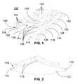
- FIG. 1is a perspective view of an optic according to an embodiment of the present invention.
- FIG. 2is a lower perspective view of the optic of FIG. 1 .
- FIG. 3is another perspective view of the optic of FIG. 1 .
- FIG. 4is a perspective view of a light source structure member to be used in connection with a lighting device according to an embodiment of the present invention.
- FIG. 5is a lower perspective view of the light source structure member of FIG. 4 .
- FIG. 6is a perspective view of the light source structure member of FIG. 4 with the optic of FIG. 1 positioned adjacent thereto.
- FIG. 7is a perspective sectional view of the light source structure member and optic of FIG. 6 taken through line 7-7.
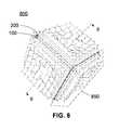
- FIG. 8is a perspective view of a lighting device according to an embodiment of the present invention.
- FIG. 9is a perspective sectional view of the lighting device of FIG. 8 taken through line 9-9.
- FIG. 10is a schematic representation of a lighting device according to an embodiment of the present invention.
- FIG. 11is a schematic representation of a lighting device according to another embodiment of the present invention.
- FIG. 12is a schematic representation of a lighting device according to another embodiment of the present invention.
- FIG. 13is a perspective view of a lighting device according to an embodiment of the present invention.
- FIG. 14is a side sectional view of the lighting device of FIG. 13 taken through line 14-14.
- FIG. 15is a schematic representation of a lighting device according to another embodiment of the present invention.
- FIG. 16is an environmental view of a lighting device according to an embodiment of the present invention installed in a room.
- the present inventionmay be referred to as relating to luminaires, digital lighting, light sources, and light-emitting diodes (LEDs).
- LEDslight-emitting diodes
- the present inventionmay just as easily relate to lasers or other digital lighting technologies.
- a person of skill in the artwill appreciate that the use of LEDs within this disclosure is not intended to be limited to any specific form of LED, and should be read to apply to light emitting semiconductors in general. Accordingly, skilled artisans should not view the following disclosure as limited to any particular light emitting semiconductor device, and should read the following disclosure broadly with respect to the same.
- the optic 100may be configured to receive light from one or more light sources and redirect that incident light in multiple directions. The direction in which the incident light is redirected may be determined by where the light is incident on the optic 100 .
- the optic 100may include a receiving section 110 , an intermediate section 120 , and an emitting section 130 .
- the intermediate section 120may be positioned between the receiving section 110 and the emitting section 130 .
- Each of the receiving section 110 , the intermediate section 120 , and the emitting section 130may be formed of transparent or translucent material. Moreover, each may be formed of the same material, or a variety of materials may be used.
- the optic 100may be formed as a single integral structure.
- one or more of the receiving section 110 , the intermediate section 120 , and the emitting section 130may be formed apart from the other parts of the optic 100 and may be attached and placed in optical communication with the adjacent parts of the optic 100 according to any means or methods known in the art. Means and methods of attachment may include, but are not limited to, fasteners, glues, optical glues, adhesives, and the like. Additionally, optical grease may be applied between the attaching portions of the optic 100 to improve optical communication therebetween.
- the receiving section 110may be configured to receive light from a light source. More specifically, the receiving section 110 may be configured to receive light from a plurality of light sources. As such, the receiving section 110 may be configured to be positioned adjacent to a plurality of light sources. In some embodiments, where the plurality of light sources are arranged in a flat, generally planar configuration, the receiving section 110 may similarly be configured to be generally planar. More specifically, the receiving section 110 may comprise a receiving surface 112 , and the receiving surface 112 may be configured to be generally flat.
- the receiving surface 112may be similarly configured to be generally arcuate, conforming to a curvature of the plurality of light sources.
- the receiving surface 112is generally flat.
- the receiving surface 112may be configured to have a geometric configuration that generally conforms to the configuration of the array of light sources.
- the receiving surface 112has a generally rectangular configuration, forming a square with rounded corners.
- This geometric configurationis exemplary only, and all other configurations are contemplated and included within the scope of the invention, including, but not limited to, circles, ovals, ellipses, triangles, and any other polygon.
- arcuate configurations of the receiving surface 112are also contemplated and included within the scope of the invention. Such configurations include, but are not limited to, spherical or semi-spherical configurations, and any other ellipsoid.
- the receiving surface 112may be configured to include optical characteristics.
- the receiving surface 112may be polished so as to facilitate the maximum transmission of light therethrough. Additionally, the receiving surface 112 may be polished so as to have little or no refraction on light incident thereupon.
- the receiving section 110may be similarly formed so as to result in little or no refraction of light passing therethrough. More specifically, a body section 114 of the receiving section 110 may be configured so as to cause little or no refraction of light passing therethrough. Additionally, in some embodiments, each of the receiving surface 112 and the body section 114 may be configured to collimate light.
- each of the receiving surface 112 and the body section 114may be configured to collimate light in a direction orthogonal to a plane defined by the receiving surface 112 .
- the planemay be flat. In other embodiments, the plane may be curved.
- the body section 114may be configured to include a plurality of collimating sections. Each collimating section may be configured to collimate light incident thereupon such that light from each collimating section does not propagate into an adjacent collimating section.
- the receiving surface 112may include a material applied thereto.
- optical greasemay be applied to the receiving surface 112 so as to facilitate the transmission of light between a light source and the receiving surface 112 when the receiving section 110 is positioned adjacent to a plurality of light sources.
- a color conversion layer(not shown) may be positioned adjacent the receiving surface 112 .
- the color conversion layermay be configured to receive light within a source wavelength range and convert the light, emitting a converted light within a converted wavelength range.
- the color conversion layermay be attached, deposited, or otherwise positioned on the receiving surface 112 by any means that is suitable to the material forming the color conversion layer.
- the receiving surface 112may include two or more color conversion layers positioned upon different sections of the receiving surface 112 . Each of the two or more color conversion layers may convert respective source lights of the same or differing wavelengths to respective converted lights of differing wavelengths.
- the receiving surface 112may include any number of color conversion layers, including overlapping layers. Color conversion layers may be formed of material selected from the group consisting of phosphors, quantum dots, luminescent materials, fluorescent materials, and dyes. More details regarding the enablement and use of a color conversion layer may be found in U.S. patent application Ser. No. 13/073,805, entitled MEMS Wavelength Converting Lighting Device and Associated Methods, filed Mar. 28, 2011, as well as U.S. patent application Ser. No.
- the body section 114may be formed of a material or a mixture of materials configured to perform a similar color conversion of light passing therethrough.
- the body section 114may include one or more side surfaces 115 .
- the number and configuration of side surfaces 115may be defined by the geometric configuration of the receiving section 110 .
- the side surfaces 115may be configured to prevent light from passing therethrough.
- the side surfaces 115may have an absorbing or reflecting material applied thereto.
- the side surfaces 115may be configured to redirect light incident thereupon emitted by the plurality of light sources and passing through the receiving surface 112 in the direction of the interfacing surface 116 .
- each of the receiving surface 112 and the body member 114may be configured to direct light so as to not be incident upon the side surfaces 115 .
- the receiving section 110may further include an interfacing surface 116 .
- the interfacing surface 116may be configured so as to facilitate the transmission of light from the receiving section 110 to the intermediate section 120 .
- the interfacing section 116may be configured to include any or all of the optical characteristics described for the receiving surface 112 and the body section 114 described hereinabove.
- the interfacing section 116may have optical grease, a color conversion layer, or other material applied to or placed adjacent thereto, in addition to or exclusive of optical grease and/or a color conversion layer associated with the receiving surface 112 .
- the interfacing surface 116may include an exposed surface 118 , being defined as the section of the interfacing surface 116 that is outside the periphery of the interface between the interfacing surface 116 and the intermediate section 120 .
- the exposed surface 118may be configured to have the same optical characteristics as the rest of the interfacing surface 116 as described hereinabove, or it may have different characteristics.
- the exposed surface 118may be configured to absorb or reflect light incident thereupon, such that no light received by the receiving section 110 from the plurality of light sources passes through and is emitted by the exposed surface 118 .
- each of the receiving surface 112 and the body section 114may be configured to direct light, either by directed collimation or refraction, received from the plurality of light sources away from the exposed section 118 such that little or no light may pass therethrough.
- the exposed surface 118may be configured to refract light incident thereupon in the direction of the interfacing surface 116 that is interfaced with the intermediate section 120 .
- the exposed surface 118may be configured to refract light so as to emit generally diffuse light.
- the interfacing surface 116may be limited to the exposed surface 118 .
- the intermediate section 120may be configured to facilitate the transmission of light from the receiving section 110 to the emitting section 130 . Accordingly, the intermediate section 120 may be configured to receive light from the receiving section 110 and to emit light so as to be received by the emitting section 130 .
- the intermediate section 120may include optical characteristics so as to affect light passing therethrough.
- the intermediate section 120may be configured to collimate light passing therethrough. More specifically, the intermediate section 120 may be configured to collimate light in a direction generally orthogonal the plane defined by the receiving surface 112 .
- the intermediate section 120may be configured to include a plurality of collimating sections. Each collimating section may be configured to collimate light incident thereupon such that light from each collimating section does not propagate into an adjacent collimating section.
- each collimating section of the intermediate section 120may be associated with a collimating section of the body section 114 such that light collimated by each collimating section of the body section 114 remains collimated and continues in the established direction of travel in the associated collimating section of the intermediate section 120 .
- each collimating section of the intermediate section 120may be associated with a single light source of a plurality of light sources.
- each collimating sectionmay be the only collimating section associated with one or more light sources of a plurality of light sources.
- the intermediate section 120may be formed so as to facilitate the optical coupling thereto.
- the intermediate section 120may have a lower surface 122 configured to interface with and optically couple to the receiving section 110 .
- the lower surface 122may be configured to interface with and optically couple to the interfacing surface 116 of the receiving section 110 .
- the lower surface 122may have a coating or layer of material applied thereto or positioned thereupon.
- a color conversion layeras described hereinabove, may be positioned adjacent to the lower surface 122 to convert light received from the receiving section 110 .
- optical greasemay be applied to the lower surface 122 to facilitate optical coupling between it and the interfacing surface 116 .
- the lower surface 122may be configured to have a geometry that is similar to or conforms to the geometry of the interfacing surface 116 .
- the lower surface 122has a generally square configuration. It is appreciated that the lower surface 122 may have a geometry conforming to any polygon. Moreover, it is appreciated that the geometry of the lower surface 122 may define a surface area. In some embodiments, the surface area of the lower surface 122 may be approximately equal to a surface area of the interfacing section 116 , such that the lower surface 122 is generally coextensive with the interfacing section 116 . In some embodiments, the lower surface 122 may have a surface area that is less than the surface area of the interfacing surface 116 . In such embodiments, the exposed surface 118 may thereby be defined as the difference in surface area resulting in a portion of the interfacing surface 116 being exposed and not covered by the lower surface 122 .
- the intermediate section 120may include an upper surface 124 configured to optically couple to the emitting section 130 .
- the upper surface 124may have any of the characteristics and additional features, including color conversion layers and optical grease, as the lower surface 122 .
- the lower and upper surfaces 122 , 124may be absent in such embodiments.
- the intermediate section 120may further include a body section 126 .
- the body section 126may be configured to facilitate the traversal of light therethrough, from the lower surface 122 to the upper surface 124 .
- the body section 126may be configured to have optical characteristics to affect light passing therethrough. Any of the characteristics as described for the body section 114 of the receiving section 110 may be included in the body section 126 of the intermediate section 120 .
- the body section 126may have one or more sidewalls 128 .
- the sidewalls 128may be configured to have a curvature 129 .
- the curvature 129may be necessitated by a difference in the surface areas of the lower surface 122 and the upper surface 124 .
- the sidewalls 128may be configured to redirect light incident thereupon, as a result of the differences in the surface areas of the lower and upper surfaces 122 , 124 , in the direction of the upper surface 124 .
- the emitting section 130may be configured to receive light from the intermediate section 120 and to emit the received light. More specifically, the emitting section 130 may be configured to emit light in such a manner so as to enable the control of the direction of light emitted from the optic 100 .
- the emitting section 130may include a plurality of facets 132 .
- Each facet 132may be configured to emit light. More specifically, each facet 132 may be configured to emit light in a particular direction. In some embodiments, each facet 132 of the plurality of facets 132 may be configured to emit light in a direction that is unique from the direction of light emitted by the other facets 132 of the plurality of facets 132 .
- the plurality of facets 132may be configured so as to enable a user to selectively emit light from a plurality of light sources, the emitted light being received by the receiving surface 112 , passing through each of the receiving section 110 and the intermediate section 120 , and being emitted by the emitting section 130 through one or more of the plurality of facets 132 in a direction selected by the user.
- lightmay be emitted by a single facet 132 of the plurality of facets 132 in a single direction, such that the optic 100 emits light only from that facet 132 , and hence only in that direction.
- each facet 132may be associated with a single light source of a plurality of light sources. Moreover, in some embodiments, each facet 132 of the plurality of facets 132 may be the only facet associated with the light source. In some other embodiments, two or more facets 132 of the plurality of facets 132 may be associated with a single light source. In some embodiments, two or more light sources may be associated with a single facet 132 . Where a single facet 132 is configured to be associated with two or more light sources, light emitted by the two or more light sources may combine to form a combined light. In some embodiments, the combined light may be a white light.
- any combination of lightmay combine to form a combined light that is a member, a light that is perceived as a combination of the two colors.
- Each facetmay have a projected surface area that corresponds and generally conforms to a section of the upper surface 124 of the intermediate section 120 .
- each facet 132may have associated with it one or more collimating sections.
- each facet 132may be associated with the light source(s) with which the associated collimating section of the intermediate section 120 is associated.
- Each facet 132 of the plurality of facets 132may include an emitting surface 134 and one or more redirecting surfaces 136 .
- the redirecting surfaces 136may be configured to redirect light in the direction of the emitting surface 134 . Accordingly, substantially all of the light emitted by the facet 132 may be emitted through the emitting surface 134 .
- the emitting surface 134may be configured so as to emit light in a selected direction.
- the emitting surface 134may be configured to emit light having a selected divergence.
- the emitting surface 134may be configured so that the divergence of light emitted therefrom is relatively low, such that a spot light is emitted by the facet 132 .
- the optic 100may be configured to emit light as a combination of a plurality of spot lights, each spot light being light emitted through each facet 132 of the plurality of facets 132 .
- the emitting section 130may be configured such that a portion 137 of the emitting section 130 is generally flat and surrounded by the plurality of facets 132 . Moreover, the generally flat portion 137 may be positioned such that the center 133 is located therein.
- each facet 132may be configured to emit light in a selected direction. More specifically, the emitting surface 134 of each facet 132 may be configured to emit light in a direction that is generally orthogonal to a plane defined by the emitting surface 134 . Accordingly, the direction in which light is emitted from each emitting surface 134 may be individual to each facet 132 , as the plane defined by the emitting surface 134 of each facet 132 may be skew to every other plane defined by the emitting surface 134 of every other facet 132 of the plurality of facets 132 .
- each facet 132may be configured to emit light in a direction such that at least one of the first and second angles formed by the line normal to the plane defined by the emitting surface 134 of the facet 132 is non-equal to the first or second angle, respectively, every other line normal to the plane defined by the emitting surface 134 of the other facets 132 of the plurality of facets 132 .
- a facet 132may be configured to emit light in a direction such that at least one of the first and second angles formed by the line normal to the emitting section 134 of the facet 132 is equal to the first and/or second angle, respectively, of a line normal to the emitting section 134 of at least one other facet 132 of the plurality of facets 132 .
- each facet 132is configured to emit light may be selected based on any desired distribution of light, either individually to each facet 132 or in various combinations of facets 132 of the plurality of facets 132 . Moreover, the direction in which each facet 132 is configured to emit light may be selected based on a pattern or methodology.
- the plurality of facets 132may be configured to emit light in a direction that is a function of the location of the facet 132 within the emitting section 130 . More specifically, the plurality of facets 132 may be configured to emit light in the direction it is a function of the location of the facet 132 relative to the center 133 of the emitting section 130 .
- each facet 132may be configured to emit light generally in the direction of a line 135 that is normal to the generally flat portion 137 of the emitting section 130 and passing through the center 133 . In some other embodiments, each facet 132 may be configured to emit light generally in a direction away from the line 135 .
- This methodology of configuring the plurality of facets 132is exemplary only, and any other pattern or methodology of configuring the plurality of facets 132 is contemplated and included within the scope of the invention.
- the plurality of facets 132may include a color conversion layer.
- the color conversion layermay be formed of any material script hereinabove.
- the color conversion layermay be positioned adjacent to the emitting surface 134 of each facet 132 .
- a color conversion materialmay be integrally formed with each facet 132 .
- a first color conversion materialmay be associated with the first facet 132
- the second color conversion materialmay be associated with a second facet 132 .
- the first color conversion materialmay be configured to emit a converted light within a first wavelength range corresponding to a first color
- the second color conversion materialmay be configured to emit a converted light within a second wavelength range corresponding to a second color.
- more than one color conversion materialmay be present and associated with a single facet 132 such that a portion of the light emitted by the facet 132 may be within a first wavelength range, and another portion of the light emitted by the facet 132 may be within a second wavelength range.
- a facet 132includes a color conversion layer configured to convert a source light within a source wavelength range and emit a converted light within a converted wavelength range, only a portion of the light that is emitted by the facet 132 may be converted, such that the light emitted by the facet 132 is a combination of light within the source wavelength range and light within the converted wavelength range.
- the light source structure member 200may include a base member 210 , a plurality of light sources 220 positioned upon the base member 210 , and a plurality of optic attachment members 230 .
- the base member 210may be configured to permit the plurality of light sources 220 to be positioned thereupon so as to emit light that is incident upon the optic 100 . More specifically, the base member 210 may be configured to permit the plurality of light sources 220 to be positioned thereupon so as to emit light that is incident upon the receiving section 110 . More specifically, the base member 210 may be configured to permit the plurality of light sources 220 to be positioned thereupon so as to emit light is incident upon the receiving section 110 such a manner so as to control the direction of light that is emitted by the optic 100 .
- the plurality of light sources 220may include a plurality of devices operable to emit light. Any type of device operable to emit light known in the art are contemplated included within the scope of the invention, including, but not limited to, light-emitting semiconductors, such as light-emitting diodes (LEDs), incandescent bulbs, florescent bulbs, including compact fluorescent lights (CFLs), arc lights, halogen, and the like.
- the plurality of light sources 220may include a plurality of LEDs 221 .
- the plurality of LEDs 221may include any type of LED known in the art.
- the LEDs 221 included in the plurality of LEDs 221may be selected based on the characteristics of light emitted thereby the characteristics of light that may be considered includes but is not limited to brightness, wavelength range, color, color temperature, luminous efficiency, luminous efficacy, and the like.
- Each LED 221 of the plurality of LEDs 221may have the same characteristics of light, or any of the characteristics may vary LED to LED.
- each LED 221 of the plurality of LEDs 221may be selected so as to emit light selected lighting characteristics when emitted by the optic 100 .
- an LED 221configured to emit light within a wavelength range corresponding to a source wavelength range for the color conversion material such that light emitted by the LED 221 is incident upon the color conversion material and the color conversion material may emit a converted light within a converted wavelength range.
- the base member 210may include an upper surface 212 , one or more side surfaces 214 , a lower surface 216 , and a thickness 218 between the upper surface 212 and the lower surface 216 .
- Each of the upper surface 212 , the lower surface 216 , and the thickness 218may be configured to permit the positioning of the plurality of light sources 220 thereupon.
- each of the upper service 212 and the lower surface 216may be configured to permit the plurality of light sources 220 to be positioned in optical communication with the optic 100 .
- the nature of the light source 220for example, its structural characteristics and light emission distribution characteristics may alter the nature of the configuration of each of the upper surface 212 and the lower surface 200 .
- the base member 210may be configured to permit each LED 221 of the plurality of LEDs 221 to be positioned in optical communication with the optic 100 . More specifically each of the upper surface 212 , the lower surface 216 , and the thickness 218 may be configured to permit each LED 221 of the plurality of LEDs 221 to be positioned in optical communication with the optic 100 .
- the lower surface 216may include a plurality of cavities 217 . Each cavity 217 may extend into the thickness 218 and may be configured to permit an LED 221 to be positioned at least partially there within. More specifically, each cavity 217 may be configured to permit a light-emitting portion of an LED 221 to be positioned therein.
- the upper surface 212may include a plurality of features 213 configured to facilitate the optical communication between the plurality of LEDs 221 and the optic 100 .
- the arrangement of the plurality of features 213 on the upper surface 212may correspond to the arrangement of the plurality cavities 217 on the lower surface 216 . More specifically, the plurality of cavities 217 may extend through the thickness 218 such that light emitted by an LED 221 positioned within each individual cavity 217 may be incident upon an associated feature 213 . Accordingly, each cavity 217 of the plurality of cavities 217 may be associated with a feature 213 of the plurality of features 213 .
- the distribution of the cavities 217 and the features 213may be configured to correspond with the distribution of the facets 132 of the optic 100 .
- each pair of a cavity 217 and a feature 213may be associated with a facet 132 of the plurality of facets 132 .
- more than one pair of a cavity 217 and a feature 213may be associated with a single facet 132 .
- a single pair of a cavity 217 and a feature 213may be associated with more than one facet 132 .
- the plurality of features 213may be configured to facilitate the optical communication between the plurality of LEDs 221 and the optic 100 .
- the plurality of features 213may have a generally sloped profile.
- the plurality of features 213may include an optical component 215 .
- the optical component 215may be formed of a transparent or translucent material. Additionally, the optical component 215 may be configured to interact with light incident thereupon and passing there through so as to alter the characteristics of the instant light. For example, in some embodiments, the optical component 215 may be configured to reflect, refract, collimate, or otherwise redirect light incident thereupon. Additionally, in some embodiments, the optical component 215 say be configured to diffuse light incident thereupon.
- each LED 221 of the plurality of LEDs 221 and emitted from the feature 213 associated with each LED 221may be incident upon the receiving surface 112 of the optic 100 . More specifically, light emitted from each feature 213 may be incident upon the receiving surface 112 and pass therethrough, and may similarly be incident upon the intermediate section 120 and past therethrough, and may finally be incident upon the emitting section 130 . More specifically, light emitted from each feature 213 may be incident upon a facet 132 of the emitting section 130 and may be emitted by the facet 132 . Hence, light emitted by a feature 213 may result in the facet 132 associated with the feature 213 emitting light.
- each feature 213As light is emitted from each feature 213 , it may be reflected, refracted, collimated, or otherwise redirected so as to be emitted by the facet 132 that is associated with the feature 213 . Such redirection may be accomplished by the inclusion of features configured to accomplish such redirection in any of the various elements of the light source structure member 200 and the optic 100 as disclosed hereinabove. Accordingly, when light is emitted from a feature 213 , light may be emitted from the optic 100 by the facet 132 in a direction that is normal to a plane defined by an emitting surface 134 of the facet 132 .
- each feature 213is associated with an LED 221 of the plurality of LEDs 221
- the light emitted from the operated LED 221may be emitted, in some embodiments, by a single facet 132 in a direction that is normal to a plane defined by the emitting surface 134 of the facet 132 . Accordingly, the direction in which light is emitted from the optic 100 may be controlled by the selective operation of the LEDs 221 of the plurality of LEDs 221 .
- the base member 210may be configured to have a geometric shape. Some embodiments, the base member 210 may be configured to have substantially the same shape as the optic 100 . More specifically, the base member 210 may be configured to have substantially the same geometric shape as the receiving section 110 of the optic 100 . In the present embodiment, the base member 210 may have a generally square shape. The base number 210 may be configured to have a shape conforming to any polygon.
- the base member 210may further include a plurality of attachment ports 222 .
- the plurality of attachment ports 222may facilitate the attachment of the base member 210 to a structure.
- the plurality of attachment ports 222may permit the base member 210 to be attached to a support structure. Such an embodiment will be discussed in greater detail hereinbelow.
- the plurality of attachment ports 222may facilitate the attachment of the base member 210 to a structural surface, such as a wall, ceiling, or floor.
- the plurality of attachment ports 222may be configured to permit the positioning of a fastener therethrough.
- the plurality of attachment ports 222may be formed as an aperture through the thickness 218 of the body member 210 , such that a fastener may pass from the upper surface 212 to the lower surface 216 and beyond. Additionally, in some embodiments, the aperture may be countersunk.
- This method of attachmentis exemplary only, and any and all other means or methods of attachment known in the art are contemplated and included within the scope of the invention.
- the optic attachment members 230may be configured to facilitate the positioning of an optic 100 adjacent to the upper surface 212 . More specifically, the optic attachment members 230 may be configured to facilitate the positioning of an optic 100 adjacent to, and in optical communication with, the plurality of features 213 of the upper surface 212 . Additionally, the optic attachment members 230 may be configured to retain and carries the optic 100 and a selected position relative to the light source structure member 200 , preventing the movement of the optic 100 relative to the light source structure member 200 . Each optic attachment member 230 may be configured as an outcropping extending generally away from the upper surface 212 . In some embodiments, the optic attachment members 230 may extend in a direction generally orthogonal to the upper surface 212 .
- Each optic attachment member 230may include a base section 232 , an extension section 234 , a rounded section 236 , and an upper section 238 .
- the base section 232may be generally adjacent to the upper surface 212 .
- the base section 232may be configured to facilitate the attachment of the optic attachment member 230 to the upper surface 212 . Any method or means of attachment as is known in the art may be used, including, but not limited to, adhesives, glues, welding, fasteners, and the like. It is contemplated included within the scope of the invention that, in some embodiments, the optic attachment members 230 may be integrally formed with the base member 210 .
- the extension section 234may extend generally away from the base section 232 in a direction generally away from the upper surface 212 .
- the extension section 234may be sloped, more specifically, maybe sloped generally inward from a perimeter defined by the base section 232 .
- the perimeter defined by the base section 232may generally define the shape of the extension section 234 .
- the base section 232is generally circular in shape, thereby defining a circular perimeter.
- the extension section 234is generally cylindrical in shape.
- the extension section 234may be generally conical in shape. More specifically, the extension section 234 may be generally frustoconical in shape.
- the rounded section 236may be positioned adjacent to an end of the extension section 234 generally opposite the base section 232 .
- the rounded section 236may be rounded inward in the direction of the upper section 238 .
- the upper section 238may define an upper end the optic attachment member 230 .
- the upper section 238may be generally flat.
- the optic attachment members 230may be configured attached to the optic 100 so as to position the optic 100 as described hereinabove. In some embodiments, the optic attachment members 230 may be configured to attach removably the optic 100 . Any means or method of attachment as is known in the art may be employed, moving, but not limited to, adhesives, glues, interference fits, frictional fits, welding, fasteners, and the like.
- the optic attachment members 230may be configured to extend into a section of the optic 100 that is configured to receive the optic attachment members 230 . More specifically, the material of each optic attachment member 230 may facilitate the attachment of the optic 100 to the optic attachment members 230 .
- the optic attachment members 230may be formed of a material having a generally increased coefficient of friction.
- the optic attachment members 230may be formed of a material that is generally compressible.
- the optic 100may generally compress the optic attachment members 230 and, more specifically, may compress at least one of the extension section 234 and the rounded section 236 , increasing the friction therebetween and attaching thereby.
- This method of attaching the optic 100 to the optic attachment members 230is exemplary only and does not limit the scope of methods of attachment.
- An optic 100 that has been attached to the light source structure member 200is illustrated, for example, in FIG. 6 .
- the optic 100may be positioned adjacent to the light source structure member 200 such that each feature 213 is positioned in optical communication with an associated facet 132 .
- a first feature 213 ′may be positioned in optical communication with a first facet 132 ′.
- a second feature 213 ′′may be positioned in optical communication with a second facet 132 ′′.
- each of the first and second features 213 ′, 213 ′′ in optical communication with each of the first and second facets 132 ′, 132 ′′will depend on the optical characteristics of all of the elements, as well as the optical characteristics generally of the light source structure member 200 and the optic 100 .
- each of the first and second features 213 ′, 213 ′′may be positioned so as to be generally vertically aligned with each associated feature 132 ′, 132 ′′, respectively. Accordingly, light may be emitted by each of the first and second features 213 ′, 213 ′′, propagate generally upwards, and be emitted by the emitting surface 134 of each of the first and second facets 132 ′, 132 ′′. Similar positioning may be adopted for the remaining facets 132 of the plurality of facets 132 and features 213 of the plurality of features 213 .
- FIGS. 6-7a single pair (or combination) of an optic 100 and a light source structure member 200 was discussed.
- more than one combination of an optic 100 and a light source structure member 200may be included in a single lighting device, each combination being referred to as a lighting structure.
- many of such lighting structuresare depicted as being included in a lighting device 800 .
- the lighting device 800may include a plurality of lighting structures 850 .
- Each lighting structure 850 of the plurality of lighting structures 850may be a combination of an optic 100 and a light source structure member 200 as described hereinabove.
- Each lighting structure 850may be positioned so as to be adjacent to at least one other lighting structure 850 of the plurality of lighting structures 850 .
- two lighting structures 850may be provided.
- the lighting structures 850may be positioned such that a first plane defined by the lower surface 216 of one of the lighting structures 850 is skew to a second plane defined by the lower surface 216 of the other lighting structure 850 .
- the first planemay be perpendicular to the second plane.
- the plurality of lighting structures 850may be positioned so as to define a geometric shape of the lighting device 800 .
- the plurality of lighting structures 850is positioned so as to define a generally cubic shape. It is contemplated, however, and intended to be included within the scope of the invention, that any other geometric configuration resulting from the positioning of the plurality of lighting devices 850 defining a shape may be arranged, including, but not limited to, pyramids, boxes, or any other polyhedron, including regular polyhedral shapes. In some embodiments, a complete polyhedron may not be defined, wherein at least one face of the polyhedron is left unoccupied by a lighting structure 850 . Such embodiments may be advantageous where the lighting device 800 is to be attached to a surface of an external structure.
- the geometric configuration of the lighting device 800may depend upon the shape of each lighting structure 850 .
- the plurality of lighting structures 850may readily be arranged to form a lighting device 800 having a generally cubic shape.
- the plurality of lighting structures 850may have a geometric configuration other than a square, and, accordingly the lighting device 800 may have a geometric configuration of the shape other than acute.
- the shape of one lighting structure 850is different from the shape of another lighting structure 850
- the geometric configuration of the lighting device 800may be determined as a result of the variation in shapes between the various lighting structures 850 .
- the plurality of lighting structures 850may be positioned so as to be immediately adjacent to one another.
- the lighting device 800may include a support structure (not shown).
- the support structuremay be configured to position the plurality of lighting structures 850 into a selected arrangement.
- the support structuremay be configured to position the plurality of lighting structures 850 into a generally cubic shape.
- Each lighting structure 850may be attached to the support structure any means or method known in the art.
- the support structuremay be configured to cooperate with the attachment ports 222 of the light source structure member 200 .
- the support structuremay be configured to permit the attachment of a fastener thereto, wherein the fastener is positioned so as to pass through an aperture of the attachment ports 222 , as shown in FIGS. 4-5 , thereby attaching the light source structure member 200 to the support structure.
- Each lighting structure 850may be similarly attached to the support structure in this manner.
- the plurality of lighting structures 850may be positioned so as to define internal cavity 810 .
- Each of the lower surfaces 216 of the light source structure members 200 of the plurality of lighting structures 850may define a boundary of the internal cavity 810 .
- Various electrical components utilized in the operation of each lighting structure 850 of the plurality of lighting structures 850may be positioned within the internal cavity 810 .
- the electrical components utilized in the operation of the plurality of lighting structures 850may be attached to and carried by support structure.
- the lighting device 1000may include electrical components to enable and control the operation of the plurality of lighting structures 1040 .
- Examples of such electrical componentsmay include a controller 1010 and a power circuit 1020 .
- the power circuit 1020may be configured to be positioned in electrical communication with an external power source 1030 , and may be configured to condition, rectify, and otherwise alter electricity received from the power source 1030 so as to be used by the various electrical components of the lighting device 1000 , including the controller 1010 and the plurality of lighting structures 1040 .
- the power circuit 1020may be positioned in electrical communication with the controller 1010 and each lighting structure of the plurality of lighting structures 1040 .
- the controller 1010 and the power circuit 1020may be contained on a single circuit board, and may be considered a single integral electronic component.
- the controller 1010may be positioned in electrical communication with each lighting structure 1040 of the plurality of lighting structures 1040 and may be configured to control the operation of each lighting structure 1040 of the plurality of lighting structures 1040 .
- the controller 1010may be positioned in electrical communication with each of a first lighting structure 1041 , a second lighting structure 1042 , and an nth lighting structure 1043 .
- the controller 1010may be configured to control the operation of the plurality of LEDs 221 of each of the plurality of lighting structures 850 .
- the controller 1010may be configured to operate a single LED 221 of the plurality of LEDs 221 , thereby causing the first feature 213 ′ of the plurality of features 213 , which is associated the single LED 221 the controller 1010 selectively operates, thereby causing the first facet 132 ′ to emit light.
- the controller 1010may be configured to selectively operate each individual LED 221 of the plurality of LEDs 221 , thereby enabling the controller 1010 to selectively emit light from each facet 132 of the plurality of facets 132 .
- the controller 1010may be configured to control the direction in which light is emitted from the lighting device 800 by selectively operating at least one LED 221 of the plurality of LEDs 221 of at least one of the plurality of lighting structures 1040 of the lighting device 800 .
- the lighting device 1100may include a controller 1110 and a power circuit 1120 .
- each of the plurality of lighting structures 1140may comprise a sub-controller 1150 . More specifically, each sub-controller 1150 of the plurality of lighting structures 1140 may be configured to be positioned in electrical communication with the controller 1110 and to receive instructions therefrom.
- each sub-controller 1150may be configured to operate the plurality of LEDs 221 of the associated lighting structure, one of the first lighting structure 1141 , the second lighting structure 1142 , or the n th lighting structure 1143 , responsive to the instructions received from the controller 1110 .
- a less sophisticated electrical electronic controller devicemay be utilized as controller 1110 , as it need only communicate and instruction to each sub-controller 1150 , which may then interpret the instruction to operate an associated plurality of LEDs according to the configuration of the sub-controller 1150 .
- the lighting device 1200includes a controller 1210 , a power circuit 1220 , and a single lighting structure 1230 .
- the controller 1210may be configured to control the operation of the lighting structure 1230 as described hereinabove.
- the lighting device 1300may include an optic 1310 and a light source structure member 1320 as described hereinabove. Furthermore, the lighting device 1300 may additionally include a reflective housing member 1330 .
- the reflective housing member 1330may include a wall 1331 having a reflective inner surface 1332 configured to reflect light incident thereupon. Additionally, the reflective inner surface 1332 may be configured to have a contour so as to selectively redirect light that is incident thereupon.
- the reflective inner surface 1332may be configured to redirect light incident thereupon in the direction of a gap 1334 between the reflective housing 1330 and the optic 1310 and the light source structure member 1320 such that light reflected by the reflective inner surface 1332 may propagate into the environment surrounding the lighting device 1300 .
- the reflective housing 1330may be configured to preserve the directional control of light emitted by the lighting device 1300 . Accordingly, the reflective housing 1330 may be configured to redirect light that is incident upon various sections of the reflective inner surface 1332 such that light emitted by a first facet 1312 of the optic 1310 may be emitted from the lighting device 1300 in a first direction, and light emitted by a second facet 1314 of the optic 1310 may be emitted from the lighting device 1300 in a second direction.
- a first facet 1312 of the optic 1310may emit light that propagates through an optical chamber 1336 defined by the reflective inner surface 1332 , is incident upon a first section 1338 ′ of the reflective inner surface 1332 , and is redirected through the gap 1334 at an angle and in a direction that is unique indistinguishable from light emitted by the second facet 1314 which is then incident upon a second section 1338 ′′ of the reflective inner surface 1332 and redirected through the gap 1334 . Accordingly, light may be emitted from any facet of the optic 1310 , reflected by the reflective inner surface 1332 , and emitted from the lighting device 1300 in a spotlight-like configuration as described hereinabove.
- the geometric configuration of the reflective housing 1330may be determined based on the geometric configuration of the optic 1310 . More specifically, where the optic 1310 has a generally square configuration, the reflective housing 1330 may similarly have a generally square configuration, whereby a lower edge 1339 of the reflective housing 1330 defines its shape.
- the reflective housing 1330may include a color conversion layer positioned adjacent to the reflective inner surface 1332 such that light emitted by the optic 1310 is received by the color conversion layer and a converted light is emitted thereby prior to being reflected out of the lighting device 1300 .
- the color conversion layermay be the substantially the same as color conversion layers described hereinabove.
- a lighting device 1500may comprise a controller 1510 , a power circuit 1520 , a plurality of lighting structures 1530 , and a network interface device 1540 .
- the network interface device 1540may be positioned in electrical communication with the controller 1510 and may be configured to transmit an instruction to the controller 1510 . Additionally, the network interface device 1540 may be configured to communicate electronically with a network 1550 .
- the network 1550may be any type of computerized network as is known in the art.
- the network interface device 1540may be configured to receive an instruction from a remote computerized device 1560 across the network 1550 .
- the network interface device 1540may be configured to then transmit the instruction to the controller 1510 .
- the controller 1510may be configured to operate the plurality of lighting structures 1530 responsive to the instructions received from the network interface device 1540 .
- the instructionmay cause the controller 1510 to operate a light source of the plurality of light sources associated with a lighting structure 1530 of the plurality of lighting structures 1530 .
- the lighting device 1600may be positioned so as to emit light into a room 1610 .
- the lighting device 1600may be configured according to any of the lighting devices described hereinabove. More specifically, the lighting device 1600 may be configured to communicate across the network 1550 as described in the lighting device represented in FIG. 15 . Accordingly, the lighting device 1600 may operate responsive to an input received across the network 1550 .
- One method of using the lighting device 1600may be to indicate a location within the room 1610 .
- the lighting device 1600may be operated so as to illuminate a first location 1612 within the room 1610 . This may be accomplished by operating a single LED of a plurality of LEDs of the lighting device 1600 , which may result in light being emitted from a single facet of the lighting device 1600 as described hereinabove. The light emitted by the single facet may result in light propagating through a volume of the room 1610 and being incident upon the first location 1612 . In this way, the lighting device 1600 may indicate to an observer the first location 1612 . The purpose of such an indication of the first location 1612 may depend entirely upon the intended use by the user.
- the first location 1612may indicate the location of a particular good.
- the first location 1612may indicate the location of a good that has run out of stock and requires restocking.
- the lighting device 1600may be operated so as to illuminate a second location 1614 within the room 1610 .
- the illumination of the second location 1614may be concurrent with the illumination of the first location 1612 , or they may occur in a sequential fashion.
- the lighting device 1600may be operated so as to illuminate a third location 1616 within the room 1610 .
- the illumination of the third location 1616may be concurrent with the illumination of each or either of the first location 1612 and the second location 1614 , or it may occur in a sequential illumination of each of the first, second, and third locations 1612 , 1614 , 1616 .
- the lighting device 1600may indicate a motion of direction by the sequential illumination of the first, second, and third locations 1612 , 1614 , 1616 .
- Thismay indicate a suggested direction of travel to an observer. This may be desirable in a retail shopping setting, where the lighting device 1600 may indicate the direction in which an observer may travel in order to find a particular location or good. Additionally, this may be desirable in emergency situations, where the lighting device 1600 may indicate a safe direction of travel towards an exit 1618 of the room 1610 .
- the lighting device 1600may be used in any method, manner, or setting in which directional illumination is desirable. More information regarding lighting scenarios may be found in U.S. patent application Ser. No. 13/464,345 entitled Occupancy Sensor and Associated Methods filed May 4, 2012, U.S. patent application Ser. No. 13/785,652 entitled Occupancy Sensor and Associated Methods filed Mar. 5, 2013, and U.S. patent application Ser. No. 13/403,531 entitled Configurable Environmental Condition Sensing Luminaire, System and Associated Methods filed Feb. 23, 2012, the contents of which are incorporated in their entirety by reference herein.
Landscapes
- Engineering & Computer Science (AREA)
- General Engineering & Computer Science (AREA)
- Non-Portable Lighting Devices Or Systems Thereof (AREA)
- Microelectronics & Electronic Packaging (AREA)
- Physics & Mathematics (AREA)
- Spectroscopy & Molecular Physics (AREA)
Abstract
Description
Claims (21)
Priority Applications (1)
| Application Number | Priority Date | Filing Date | Title |
|---|---|---|---|
| US14/076,621US9429294B2 (en) | 2013-11-11 | 2013-11-11 | System for directional control of light and associated methods |
Applications Claiming Priority (1)
| Application Number | Priority Date | Filing Date | Title |
|---|---|---|---|
| US14/076,621US9429294B2 (en) | 2013-11-11 | 2013-11-11 | System for directional control of light and associated methods |
Publications (2)
| Publication Number | Publication Date |
|---|---|
| US20150131281A1 US20150131281A1 (en) | 2015-05-14 |
| US9429294B2true US9429294B2 (en) | 2016-08-30 |
Family
ID=53043649
Family Applications (1)
| Application Number | Title | Priority Date | Filing Date |
|---|---|---|---|
| US14/076,621Expired - Fee RelatedUS9429294B2 (en) | 2013-11-11 | 2013-11-11 | System for directional control of light and associated methods |
Country Status (1)
| Country | Link |
|---|---|
| US (1) | US9429294B2 (en) |
Families Citing this family (3)
| Publication number | Priority date | Publication date | Assignee | Title |
|---|---|---|---|---|
| DE102015112848A1 (en)* | 2015-08-05 | 2017-02-09 | Luke Roberts Gmbh | Improved room light |
| US10365351B2 (en)* | 2017-03-17 | 2019-07-30 | Waymo Llc | Variable beam spacing, timing, and power for vehicle sensors |
| US10468566B2 (en)* | 2017-04-10 | 2019-11-05 | Ideal Industries Lighting Llc | Hybrid lens for controlled light distribution |
Citations (171)
| Publication number | Priority date | Publication date | Assignee | Title |
|---|---|---|---|---|
| US5057908A (en) | 1990-07-10 | 1991-10-15 | Iowa State University Research Foundation, Inc. | High power semiconductor device with integral heat sink |
| US5523878A (en) | 1994-06-30 | 1996-06-04 | Texas Instruments Incorporated | Self-assembled monolayer coating for micro-mechanical devices |
| US5704701A (en) | 1992-03-05 | 1998-01-06 | Rank Brimar Limited | Spatial light modulator system |
| US5997150A (en) | 1995-10-25 | 1999-12-07 | Texas Instruments Incorporated | Multiple emitter illuminator engine |
| US6140646A (en) | 1998-12-17 | 2000-10-31 | Sarnoff Corporation | Direct view infrared MEMS structure |
| US6290382B1 (en) | 1998-08-17 | 2001-09-18 | Ppt Vision, Inc. | Fiber bundle combiner and led illumination system and method |
| US6341876B1 (en) | 1997-02-19 | 2002-01-29 | Digital Projection Limited | Illumination system |
| US6356700B1 (en) | 1998-06-08 | 2002-03-12 | Karlheinz Strobl | Efficient light engine systems, components and methods of manufacture |
| US6370168B1 (en) | 1999-10-20 | 2002-04-09 | Coherent, Inc. | Intracavity frequency-converted optically-pumped semiconductor laser |
| US20020151941A1 (en) | 2001-04-16 | 2002-10-17 | Shinichi Okawa | Medical illuminator, and medical apparatus having the medical illuminator |
| US6542671B1 (en) | 2001-12-12 | 2003-04-01 | Super Light Wave Corp. | Integrated 3-dimensional multi-layer thin-film optical couplers and attenuators |
| US6561656B1 (en) | 2001-09-17 | 2003-05-13 | Mitsubishi Denki Kabushiki Kaisha | Illumination optical system with reflecting light valve |
| US6594090B2 (en) | 2001-08-27 | 2003-07-15 | Eastman Kodak Company | Laser projection display system |
| US6647199B1 (en) | 1996-12-12 | 2003-11-11 | Teledyne Lighting And Display Products, Inc. | Lighting apparatus having low profile |
| US6707611B2 (en) | 1999-10-08 | 2004-03-16 | 3M Innovative Properties Company | Optical film with variable angle prisms |
| US20040052076A1 (en) | 1997-08-26 | 2004-03-18 | Mueller George G. | Controlled lighting methods and apparatus |
| US6733135B2 (en) | 2002-04-02 | 2004-05-11 | Samsung Electronics Co., Ltd. | Image projection apparatus |
| US6767111B1 (en) | 2003-02-26 | 2004-07-27 | Kuo-Yen Lai | Projection light source from light emitting diodes |
| US6787999B2 (en) | 2002-10-03 | 2004-09-07 | Gelcore, Llc | LED-based modular lamp |
| US6793374B2 (en)* | 1998-09-17 | 2004-09-21 | Simon H. A. Begemann | LED lamp |
| US6799864B2 (en) | 2001-05-26 | 2004-10-05 | Gelcore Llc | High power LED power pack for spot module illumination |
| US6817735B2 (en) | 2001-05-24 | 2004-11-16 | Matsushita Electric Industrial Co., Ltd. | Illumination light source |
| US6870523B1 (en) | 2000-06-07 | 2005-03-22 | Genoa Color Technologies | Device, system and method for electronic true color display |
| US6871982B2 (en) | 2003-01-24 | 2005-03-29 | Digital Optics International Corporation | High-density illumination system |
| US6893140B2 (en) | 2002-12-13 | 2005-05-17 | W. T. Storey, Inc. | Flashlight |
| US6945672B2 (en) | 2002-08-30 | 2005-09-20 | Gelcore Llc | LED planar light source and low-profile headlight constructed therewith |
| US6948838B2 (en)* | 2002-01-15 | 2005-09-27 | Fer Fahrzeugelektrik Gmbh | Vehicle lamp having prismatic element |
| US6964501B2 (en) | 2002-12-24 | 2005-11-15 | Altman Stage Lighting Co., Ltd. | Peltier-cooled LED lighting assembly |
| US6967761B2 (en) | 2000-10-31 | 2005-11-22 | Microsoft Corporation | Microelectrical mechanical structure (MEMS) optical modulator and optical display system |
| US6974713B2 (en) | 2000-08-11 | 2005-12-13 | Reflectivity, Inc. | Micromirrors with mechanisms for enhancing coupling of the micromirrors with electrostatic fields |
| US20060002110A1 (en) | 2004-03-15 | 2006-01-05 | Color Kinetics Incorporated | Methods and systems for providing lighting systems |
| US20060002108A1 (en) | 2004-06-30 | 2006-01-05 | Ouderkirk Andrew J | Phosphor based illumination system having a short pass reflector and method of making same |
| US7042623B1 (en) | 2004-10-19 | 2006-05-09 | Reflectivity, Inc | Light blocking layers in MEMS packages |
| US20060103777A1 (en) | 2004-11-15 | 2006-05-18 | 3M Innovative Properties Company | Optical film having a structured surface with rectangular based prisms |
| US7070281B2 (en) | 2002-12-04 | 2006-07-04 | Nec Viewtechnology, Ltd. | Light source device and projection display |
| US7072096B2 (en) | 2001-12-14 | 2006-07-04 | Digital Optics International, Corporation | Uniform illumination system |
| US7075707B1 (en) | 1998-11-25 | 2006-07-11 | Research Foundation Of The University Of Central Florida, Incorporated | Substrate design for optimized performance of up-conversion phosphors utilizing proper thermal management |
| US20060164005A1 (en) | 2005-01-25 | 2006-07-27 | Chuan-Sheng Sun | Illumination apparatus having adjustable color temperature and method for adjusting the color temperature |
| US7083304B2 (en) | 2003-08-01 | 2006-08-01 | Illumination Management Solutions, Inc. | Apparatus and method of using light sources of differing wavelengths in an unitized beam |
| US20060285193A1 (en) | 2005-06-03 | 2006-12-21 | Fuji Photo Film Co., Ltd. | Optical modulation element array |
| US20070013871A1 (en) | 2005-07-15 | 2007-01-18 | Marshall Stephen W | Light-emitting diode (LED) illumination in display systems using spatial light modulators (SLM) |
| US7178941B2 (en) | 2003-05-05 | 2007-02-20 | Color Kinetics Incorporated | Lighting methods and systems |
| US7178946B2 (en) | 2002-09-10 | 2007-02-20 | Honeywell International, Inc. | Luminaire device that restricts light within an angular envelope |
| US20070041167A1 (en) | 2005-08-19 | 2007-02-22 | Dai-Ichi Shomei Co., Ltd. | Medical lighting apparatus |
| US7184201B2 (en) | 2004-11-02 | 2007-02-27 | Texas Instruments Incorporated | Digital micro-mirror device having improved contrast and method for the same |
| US7246923B2 (en) | 2004-02-11 | 2007-07-24 | 3M Innovative Properties Company | Reshaping light source modules and illumination systems using the same |
| US7255469B2 (en) | 2004-06-30 | 2007-08-14 | 3M Innovative Properties Company | Phosphor based illumination system having a light guide and an interference reflector |
| US20070188847A1 (en) | 2006-02-14 | 2007-08-16 | Texas Instruments Incorporated | MEMS device and method |
| US7261453B2 (en) | 2005-01-25 | 2007-08-28 | Morejon Israel J | LED polarizing optics for color illumination system and method of using same |
| US20070241340A1 (en) | 2006-04-17 | 2007-10-18 | Pan Shaoher X | Micro-mirror based display device having an improved light source |
| US7289090B2 (en) | 2003-12-10 | 2007-10-30 | Texas Instruments Incorporated | Pulsed LED scan-ring array for boosting display system lumens |
| US7300177B2 (en) | 2004-02-11 | 2007-11-27 | 3M Innovative Properties | Illumination system having a plurality of light source modules disposed in an array with a non-radially symmetrical aperture |
| US7303291B2 (en) | 2004-03-31 | 2007-12-04 | Sanyo Electric Co., Ltd. | Illumination apparatus and video projection display system |
| US7306352B2 (en) | 2004-10-19 | 2007-12-11 | Samsung Electronics Co., Ltd. | Illuminator |
| US7325956B2 (en) | 2005-01-25 | 2008-02-05 | Jabil Circuit, Inc. | Light-emitting diode (LED) illumination system for a digital micro-mirror device (DMD) and method of providing same |
| US7342658B2 (en) | 2005-12-28 | 2008-03-11 | Eastman Kodak Company | Programmable spectral imaging system |
| US7344280B2 (en) | 2002-09-30 | 2008-03-18 | Teledyne Lighting And Display Products, Inc. | Illuminator assembly |
| US7344279B2 (en) | 2003-12-11 | 2008-03-18 | Philips Solid-State Lighting Solutions, Inc. | Thermal management methods and apparatus for lighting devices |
| US7349095B2 (en) | 2005-05-19 | 2008-03-25 | Casio Computer Co., Ltd. | Light source apparatus and projection apparatus |
| US7353859B2 (en) | 2004-11-24 | 2008-04-08 | General Electric Company | Heat sink with microchannel cooling for power devices |
| US7382632B2 (en) | 2005-04-06 | 2008-06-03 | International Business Machines Corporation | Computer acoustic baffle and cable management system |
| US7382091B2 (en) | 2005-07-27 | 2008-06-03 | Lung-Chien Chen | White light emitting diode using phosphor excitation |
| US20080143973A1 (en) | 2006-10-12 | 2008-06-19 | Jing Miau Wu | Light source device of laser LED and projector having the same device |
| EP1950491A1 (en) | 2007-01-26 | 2008-07-30 | Piper Lux S.r.l. | LED spotlight |
| US20080198572A1 (en) | 2007-02-21 | 2008-08-21 | Medendorp Nicholas W | LED lighting systems including luminescent layers on remote reflectors |
| US7427146B2 (en) | 2004-02-11 | 2008-09-23 | 3M Innovative Properties Company | Light-collecting illumination system |
| US20080232084A1 (en) | 2007-03-19 | 2008-09-25 | Nec Lighting, Ltd | White light source device |
| US20080232116A1 (en) | 2007-03-22 | 2008-09-25 | Led Folio Corporation | Lighting device for a recessed light fixture |
| US7429983B2 (en) | 2005-11-01 | 2008-09-30 | Cheetah Omni, Llc | Packet-based digital display system |
| US7431489B2 (en) | 2004-11-17 | 2008-10-07 | Fusion Optix Inc. | Enhanced light fixture |
| US7434946B2 (en) | 2005-06-17 | 2008-10-14 | Texas Instruments Incorporated | Illumination system with integrated heat dissipation device for use in display systems employing spatial light modulators |
| US7438443B2 (en) | 2003-09-19 | 2008-10-21 | Ricoh Company, Limited | Lighting device, image-reading device, color-document reading apparatus, image-forming apparatus, projection apparatus |
| WO2008137732A1 (en) | 2007-05-04 | 2008-11-13 | Koninklijke Philips Electronics N V | Led-based fixtures and related methods for thermal management |
| US7476016B2 (en) | 2005-06-28 | 2009-01-13 | Seiko Instruments Inc. | Illuminating device and display device including the same |
| US20090059099A1 (en) | 2007-09-05 | 2009-03-05 | Samsung Electronics Co., Ltd. | Illumination device and projection system having the same |
| US20090059585A1 (en) | 2007-08-29 | 2009-03-05 | Young Optics Inc. | Illumination system |
| WO2009040703A2 (en) | 2007-09-27 | 2009-04-02 | Philips Intellectual Property & Standards Gmbh | Lighting device and method of cooling a lighting device |
| US7530708B2 (en) | 2004-10-04 | 2009-05-12 | Lg Electronics Inc. | Surface emitting light source and projection display device using the same |
| US20090128781A1 (en) | 2006-06-13 | 2009-05-21 | Kenneth Li | LED multiplexer and recycler and micro-projector incorporating the Same |
| US7537347B2 (en) | 2005-11-29 | 2009-05-26 | Texas Instruments Incorporated | Method of combining dispersed light sources for projection display |
| US7540616B2 (en) | 2005-12-23 | 2009-06-02 | 3M Innovative Properties Company | Polarized, multicolor LED-based illumination source |
| US20090141506A1 (en) | 2007-12-03 | 2009-06-04 | Shih-Chi Lan | Illumination Device for Kitchen Hood |
| US7545569B2 (en) | 2006-01-13 | 2009-06-09 | Avery Dennison Corporation | Optical apparatus with flipped compound prism structures |
| USD593963S1 (en) | 2008-04-23 | 2009-06-09 | 4187318 Canada Inc. | Modular heat sink |
| US7556406B2 (en) | 2003-03-31 | 2009-07-07 | Lumination Llc | Led light with active cooling |
| US20090232683A1 (en) | 2006-12-09 | 2009-09-17 | Murata Manufacturing Co., Ltd. | Piezoelectric micro-blower |
| US7598686B2 (en) | 1997-12-17 | 2009-10-06 | Philips Solid-State Lighting Solutions, Inc. | Organic light emitting diode methods and apparatus |
| US7605971B2 (en) | 2003-11-01 | 2009-10-20 | Silicon Quest Kabushiki-Kaisha | Plurality of hidden hinges for mircromirror device |
| US7626755B2 (en) | 2007-01-31 | 2009-12-01 | Panasonic Corporation | Wavelength converter and two-dimensional image display device |
| US20090310356A1 (en)* | 2008-06-13 | 2009-12-17 | Koninklijke Philips Electronics N.V. | Orientable lens for an led fixture |
| US20100006762A1 (en) | 2007-03-27 | 2010-01-14 | Kabushiki Kaisha Toshiba | Scintillator panel and radiation detector |
| US20100039704A1 (en) | 2006-10-27 | 2010-02-18 | Hideki Hayashi | Prism sheet and optical sheet |
| US7670021B2 (en) | 2007-09-27 | 2010-03-02 | Enertron, Inc. | Method and apparatus for thermally effective trim for light fixture |
| US7677736B2 (en) | 2004-02-27 | 2010-03-16 | Panasonic Corporation | Illumination light source and two-dimensional image display using same |
| US7684007B2 (en) | 2004-08-23 | 2010-03-23 | The Boeing Company | Adaptive and interactive scene illumination |
| US20100084984A1 (en)* | 2007-03-02 | 2010-04-08 | Institutio Tecnologico y de estudios Superiores de Monterrey | Energy-Saving LED-Based Lighting Device |
| US7703943B2 (en) | 2007-05-07 | 2010-04-27 | Intematix Corporation | Color tunable light source |
| US20100103389A1 (en) | 2008-10-28 | 2010-04-29 | Mcvea Kenneth Brian | Multi-MEMS Single Package MEMS Device |
| US7709811B2 (en) | 2007-07-03 | 2010-05-04 | Conner Arlie R | Light emitting diode illumination system |
| US7719766B2 (en) | 2007-06-20 | 2010-05-18 | Texas Instruments Incorporated | Illumination source and method therefor |
| US7748870B2 (en) | 2008-06-03 | 2010-07-06 | Li-Hong Technological Co., Ltd. | LED lamp bulb structure |
| US7762315B2 (en) | 2008-02-01 | 2010-07-27 | Asia Vital Components Co., Ltd. | Sectional modular heat sink |
| US7766490B2 (en) | 2006-12-13 | 2010-08-03 | Philips Lumileds Lighting Company, Llc | Multi-color primary light generation in a projection system using LEDs |
| US7771085B2 (en) | 2007-01-16 | 2010-08-10 | Steven Kim | Circular LED panel light |
| US20100202129A1 (en) | 2009-01-21 | 2010-08-12 | Abu-Ageel Nayef M | Illumination system utilizing wavelength conversion materials and light recycling |
| US20100244700A1 (en) | 2007-12-24 | 2010-09-30 | Patrick Chong | System for Representing Colors Including an Integrating Light Capsule |
| US7819556B2 (en) | 2006-12-22 | 2010-10-26 | Nuventix, Inc. | Thermal management system for LED array |
| US7824075B2 (en) | 2006-06-08 | 2010-11-02 | Lighting Science Group Corporation | Method and apparatus for cooling a lightbulb |
| US7828453B2 (en) | 2009-03-10 | 2010-11-09 | Nepes Led Corporation | Light emitting device and lamp-cover structure containing luminescent material |
| US7835056B2 (en) | 2005-05-13 | 2010-11-16 | Her Majesty the Queen in Right of Canada, as represented by Institut National d'Optique | Image projector with flexible reflective analog modulator |
| US7834867B2 (en) | 2006-04-11 | 2010-11-16 | Microvision, Inc. | Integrated photonics module and devices using integrated photonics modules |
| US7832878B2 (en) | 2006-03-06 | 2010-11-16 | Innovations In Optics, Inc. | Light emitting diode projection system |
| US20100315320A1 (en) | 2007-12-07 | 2010-12-16 | Sony Corporation | Light source device and display device |
| US20100321641A1 (en) | 2008-02-08 | 2010-12-23 | Koninklijke Philips Electronics N.V. | Light module device |
| US7883241B2 (en) | 2008-05-06 | 2011-02-08 | Asustek Computer Inc. | Electronic device and heat dissipation unit thereof |
| US7889430B2 (en) | 2006-05-09 | 2011-02-15 | Ostendo Technologies, Inc. | LED-based high efficiency illumination systems for use in projection systems |
| US20110038151A1 (en)* | 2009-08-14 | 2011-02-17 | Carraher Timothy J | Led optical system |
| US7906722B2 (en) | 2005-04-19 | 2011-03-15 | Palo Alto Research Center Incorporated | Concentrating solar collector with solid optical element |
| US7922356B2 (en) | 2008-07-31 | 2011-04-12 | Lighting Science Group Corporation | Illumination apparatus for conducting and dissipating heat from a light source |
| US7923748B2 (en) | 2003-08-21 | 2011-04-12 | Excelitas Technologies LED Solutions, Inc. | Integrated LED heat sink |
| US7928565B2 (en) | 2004-06-15 | 2011-04-19 | International Business Machines Corporation | Semiconductor device with a high thermal dissipation efficiency |
| US7976205B2 (en) | 2005-08-31 | 2011-07-12 | Osram Opto Semiconductors Gmbh | Light-emitting module, particularly for use in an optical projection apparatus |
| US20110205738A1 (en) | 2010-02-25 | 2011-08-25 | Lunera Lighting Inc. | Troffer-style light fixture with cross-lighting |
| US8016443B2 (en) | 2008-05-02 | 2011-09-13 | Light Prescriptions Innovators, Llc | Remote-phosphor LED downlight |
| US8021019B2 (en) | 2008-10-15 | 2011-09-20 | Power Data Communications Co., Ltd. | Light-emitting diode lighting device with multiple-layered source |
| US8038314B2 (en) | 2009-01-21 | 2011-10-18 | Cooper Technologies Company | Light emitting diode troffer |
| US8047660B2 (en) | 2005-09-13 | 2011-11-01 | Texas Instruments Incorporated | Projection system and method including spatial light modulator and compact diffractive optics |
| US8061857B2 (en) | 2008-11-21 | 2011-11-22 | Hong Kong Applied Science And Technology Research Institute Co. Ltd. | LED light shaping device and illumination system |
| US8070324B2 (en) | 2008-07-30 | 2011-12-06 | Mp Design Inc. | Thermal control system for a light-emitting diode fixture |
| US8070302B2 (en) | 2005-05-10 | 2011-12-06 | Iwasaki Electric Co., Ltd. | Laminate type light-emitting diode device, and reflection type light-emitting diode unit |
| US20110298371A1 (en)* | 2010-06-08 | 2011-12-08 | Cree, Inc. | Led light bulbs |
| US8083364B2 (en) | 2008-12-29 | 2011-12-27 | Osram Sylvania Inc. | Remote phosphor LED illumination system |
| US8096668B2 (en) | 2008-01-16 | 2012-01-17 | Abu-Ageel Nayef M | Illumination systems utilizing wavelength conversion materials |
| EP2410240A1 (en) | 2009-03-17 | 2012-01-25 | Fediel System, S. L. | Optical device for an led light bulb |
| US8125776B2 (en) | 2010-02-23 | 2012-02-28 | Journée Lighting, Inc. | Socket and heat sink unit for use with removable LED light module |
| US20120051041A1 (en) | 2010-08-31 | 2012-03-01 | Cree, Inc. | Troffer-Style Fixture |
| US20120106144A1 (en) | 2010-10-28 | 2012-05-03 | Hon Hai Precision Industry Co., Ltd. | Led tube lamp |
| US8201968B2 (en) | 2009-10-05 | 2012-06-19 | Lighting Science Group Corporation | Low profile light |
| US20120201034A1 (en) | 2009-09-25 | 2012-08-09 | Chia-Mao Li | Wide-Range Reflective Structure |
| US8251561B2 (en) | 2009-06-05 | 2012-08-28 | Sharp Kabushiki Kaisha | Light collimating lightguide |
| US20120217861A1 (en) | 2011-02-24 | 2012-08-30 | Soni Vimal J | LED Heat Sink Assembly |
| US20120218774A1 (en) | 2011-02-28 | 2012-08-30 | Livingston Troy W | Led light bulb |
| US20120224363A1 (en)* | 2011-03-03 | 2012-09-06 | Van De Ven Antony P | Tunable remote phosphor constructs |
| US20120236598A1 (en) | 2011-03-16 | 2012-09-20 | GE Lighting Solutions, LLC | Edge-illuminated flat panel and light module for same |
| US8272763B1 (en) | 2009-10-02 | 2012-09-25 | Genesis LED Solutions | LED luminaire |
| US20120262921A1 (en) | 2009-10-05 | 2012-10-18 | Lighting Science Group Corporation | Low profile light and accessory kit for the same |
| US20120262902A1 (en) | 2011-04-18 | 2012-10-18 | Cree, Inc. | Led luminaire including a thin phosphor layer applied to a remote reflector |
| US20120268894A1 (en) | 2011-04-25 | 2012-10-25 | Journee Lighting, Inc. | Socket and heat sink unit for use with removable led light module |
| US8297798B1 (en) | 2010-04-16 | 2012-10-30 | Cooper Technologies Company | LED lighting fixture |
| US8297783B2 (en) | 2008-09-10 | 2012-10-30 | Samsung Electronics Co., Ltd. | Light emitting device and system providing white light with various color temperatures |
| US8322889B2 (en) | 2006-09-12 | 2012-12-04 | GE Lighting Solutions, LLC | Piezofan and heat sink system for enhanced heat transfer |
| US8331099B2 (en) | 2006-06-16 | 2012-12-11 | Robert Bosch Gmbh | Method for fixing an electrical or an electronic component, particularly a printed-circuit board, in a housing and fixing element therefor |
| US8328406B2 (en) | 2009-05-13 | 2012-12-11 | Oree, Inc. | Low-profile illumination device |
| US8337063B2 (en) | 2009-08-25 | 2012-12-25 | Stanley Electric Co., Ltd. | Vehicle light |
| US8337029B2 (en) | 2008-01-17 | 2012-12-25 | Intematix Corporation | Light emitting device with phosphor wavelength conversion |
| US20120327650A1 (en) | 2011-06-27 | 2012-12-27 | Cree, Inc. | Direct and back view led lighting system |
| US20130021792A1 (en) | 2011-07-24 | 2013-01-24 | Cree, Inc. | Modular indirect suspended/ceiling mount fixture |
| US8419249B2 (en) | 2009-04-15 | 2013-04-16 | Stanley Electric Co., Ltd. | Liquid-cooled LED lighting device |
| US8427590B2 (en) | 2009-05-29 | 2013-04-23 | Soraa, Inc. | Laser based display method and system |
| US20130120963A1 (en) | 2009-10-05 | 2013-05-16 | Lighting Science Group Corporation | Low profile light having concave reflector and associated methods |
| US8459856B2 (en) | 2007-12-19 | 2013-06-11 | Oree, Inc. | Planar white illumination apparatus |
| US20130223055A1 (en) | 2009-10-05 | 2013-08-29 | Lighting Science Group Corporation | Low profile light having elongated reflector and associated methods |
| US8531126B2 (en) | 2008-02-13 | 2013-09-10 | Canon Components, Inc. | White light emitting apparatus and line illuminator using the same in image reading apparatus |
| US20130294071A1 (en) | 2012-05-03 | 2013-11-07 | Lighting Science Group Corporation | Luminaire with prismatic optic |
| US20130294087A1 (en) | 2012-05-03 | 2013-11-07 | Lighting Science Group Corporation | Luminaire with prismatic optic |
| US20130301238A1 (en) | 2012-05-03 | 2013-11-14 | Lighting Science Group Corporation | Luminaire having a vented enclosure |
| US8585242B2 (en) | 2010-02-04 | 2013-11-19 | Sternberg Lanterns, Inc. | Lighting system with light-emitting diodes and securing structure |
| US8608348B2 (en) | 2011-05-13 | 2013-12-17 | Lighting Science Group Corporation | Sealed electrical device with cooling system and associated methods |
| US8608341B2 (en) | 2011-03-07 | 2013-12-17 | Lighting Science Group Corporation | LED luminaire |
| US8616736B2 (en) | 2008-08-26 | 2013-12-31 | Dingguo Pan | Circular light-reflecting plate with triangular oriented prisms having identical cross section and circular plate lamp made therefrom |
| US8662672B2 (en) | 2007-10-08 | 2014-03-04 | Koninklijke Philips N.V. | Lighting device, array of lighting devices and optical projection device |
- 2013
- 2013-11-11USUS14/076,621patent/US9429294B2/ennot_activeExpired - Fee Related
Patent Citations (177)
| Publication number | Priority date | Publication date | Assignee | Title |
|---|---|---|---|---|
| US5057908A (en) | 1990-07-10 | 1991-10-15 | Iowa State University Research Foundation, Inc. | High power semiconductor device with integral heat sink |
| US5704701A (en) | 1992-03-05 | 1998-01-06 | Rank Brimar Limited | Spatial light modulator system |
| US5523878A (en) | 1994-06-30 | 1996-06-04 | Texas Instruments Incorporated | Self-assembled monolayer coating for micro-mechanical devices |
| US5997150A (en) | 1995-10-25 | 1999-12-07 | Texas Instruments Incorporated | Multiple emitter illuminator engine |
| US6647199B1 (en) | 1996-12-12 | 2003-11-11 | Teledyne Lighting And Display Products, Inc. | Lighting apparatus having low profile |
| US6341876B1 (en) | 1997-02-19 | 2002-01-29 | Digital Projection Limited | Illumination system |
| US20040052076A1 (en) | 1997-08-26 | 2004-03-18 | Mueller George G. | Controlled lighting methods and apparatus |
| US7845823B2 (en) | 1997-08-26 | 2010-12-07 | Philips Solid-State Lighting Solutions, Inc. | Controlled lighting methods and apparatus |
| US7598686B2 (en) | 1997-12-17 | 2009-10-06 | Philips Solid-State Lighting Solutions, Inc. | Organic light emitting diode methods and apparatus |
| US6356700B1 (en) | 1998-06-08 | 2002-03-12 | Karlheinz Strobl | Efficient light engine systems, components and methods of manufacture |
| US6290382B1 (en) | 1998-08-17 | 2001-09-18 | Ppt Vision, Inc. | Fiber bundle combiner and led illumination system and method |
| US6793374B2 (en)* | 1998-09-17 | 2004-09-21 | Simon H. A. Begemann | LED lamp |
| US7075707B1 (en) | 1998-11-25 | 2006-07-11 | Research Foundation Of The University Of Central Florida, Incorporated | Substrate design for optimized performance of up-conversion phosphors utilizing proper thermal management |
| US6140646A (en) | 1998-12-17 | 2000-10-31 | Sarnoff Corporation | Direct view infrared MEMS structure |
| US6707611B2 (en) | 1999-10-08 | 2004-03-16 | 3M Innovative Properties Company | Optical film with variable angle prisms |
| US6370168B1 (en) | 1999-10-20 | 2002-04-09 | Coherent, Inc. | Intracavity frequency-converted optically-pumped semiconductor laser |
| US6870523B1 (en) | 2000-06-07 | 2005-03-22 | Genoa Color Technologies | Device, system and method for electronic true color display |
| US6974713B2 (en) | 2000-08-11 | 2005-12-13 | Reflectivity, Inc. | Micromirrors with mechanisms for enhancing coupling of the micromirrors with electrostatic fields |
| US6967761B2 (en) | 2000-10-31 | 2005-11-22 | Microsoft Corporation | Microelectrical mechanical structure (MEMS) optical modulator and optical display system |
| US20050033119A1 (en) | 2001-04-16 | 2005-02-10 | J. Morita Manufacturing Corporation | Medical illuminator, and medical apparatus having the medical illuminator |
| US20020151941A1 (en) | 2001-04-16 | 2002-10-17 | Shinichi Okawa | Medical illuminator, and medical apparatus having the medical illuminator |
| US6817735B2 (en) | 2001-05-24 | 2004-11-16 | Matsushita Electric Industrial Co., Ltd. | Illumination light source |
| US6799864B2 (en) | 2001-05-26 | 2004-10-05 | Gelcore Llc | High power LED power pack for spot module illumination |
| US6594090B2 (en) | 2001-08-27 | 2003-07-15 | Eastman Kodak Company | Laser projection display system |
| US6561656B1 (en) | 2001-09-17 | 2003-05-13 | Mitsubishi Denki Kabushiki Kaisha | Illumination optical system with reflecting light valve |
| US6542671B1 (en) | 2001-12-12 | 2003-04-01 | Super Light Wave Corp. | Integrated 3-dimensional multi-layer thin-film optical couplers and attenuators |
| US7400439B2 (en) | 2001-12-14 | 2008-07-15 | Digital Optics International Corporation | Uniform illumination system |
| US7072096B2 (en) | 2001-12-14 | 2006-07-04 | Digital Optics International, Corporation | Uniform illumination system |
| US6948838B2 (en)* | 2002-01-15 | 2005-09-27 | Fer Fahrzeugelektrik Gmbh | Vehicle lamp having prismatic element |
| US6733135B2 (en) | 2002-04-02 | 2004-05-11 | Samsung Electronics Co., Ltd. | Image projection apparatus |
| US6945672B2 (en) | 2002-08-30 | 2005-09-20 | Gelcore Llc | LED planar light source and low-profile headlight constructed therewith |
| US7178946B2 (en) | 2002-09-10 | 2007-02-20 | Honeywell International, Inc. | Luminaire device that restricts light within an angular envelope |
| US7344280B2 (en) | 2002-09-30 | 2008-03-18 | Teledyne Lighting And Display Products, Inc. | Illuminator assembly |
| US6787999B2 (en) | 2002-10-03 | 2004-09-07 | Gelcore, Llc | LED-based modular lamp |
| US7070281B2 (en) | 2002-12-04 | 2006-07-04 | Nec Viewtechnology, Ltd. | Light source device and projection display |
| US6893140B2 (en) | 2002-12-13 | 2005-05-17 | W. T. Storey, Inc. | Flashlight |
| US6964501B2 (en) | 2002-12-24 | 2005-11-15 | Altman Stage Lighting Co., Ltd. | Peltier-cooled LED lighting assembly |
| US6871982B2 (en) | 2003-01-24 | 2005-03-29 | Digital Optics International Corporation | High-density illumination system |
| US7520642B2 (en) | 2003-01-24 | 2009-04-21 | Digital Optics International Corporation | High-density illumination system |
| US6767111B1 (en) | 2003-02-26 | 2004-07-27 | Kuo-Yen Lai | Projection light source from light emitting diodes |
| US7556406B2 (en) | 2003-03-31 | 2009-07-07 | Lumination Llc | Led light with active cooling |
| US7178941B2 (en) | 2003-05-05 | 2007-02-20 | Color Kinetics Incorporated | Lighting methods and systems |
| US7083304B2 (en) | 2003-08-01 | 2006-08-01 | Illumination Management Solutions, Inc. | Apparatus and method of using light sources of differing wavelengths in an unitized beam |
| US7923748B2 (en) | 2003-08-21 | 2011-04-12 | Excelitas Technologies LED Solutions, Inc. | Integrated LED heat sink |
| US7438443B2 (en) | 2003-09-19 | 2008-10-21 | Ricoh Company, Limited | Lighting device, image-reading device, color-document reading apparatus, image-forming apparatus, projection apparatus |
| US7605971B2 (en) | 2003-11-01 | 2009-10-20 | Silicon Quest Kabushiki-Kaisha | Plurality of hidden hinges for mircromirror device |
| US7289090B2 (en) | 2003-12-10 | 2007-10-30 | Texas Instruments Incorporated | Pulsed LED scan-ring array for boosting display system lumens |
| US7344279B2 (en) | 2003-12-11 | 2008-03-18 | Philips Solid-State Lighting Solutions, Inc. | Thermal management methods and apparatus for lighting devices |
| US7246923B2 (en) | 2004-02-11 | 2007-07-24 | 3M Innovative Properties Company | Reshaping light source modules and illumination systems using the same |
| US7300177B2 (en) | 2004-02-11 | 2007-11-27 | 3M Innovative Properties | Illumination system having a plurality of light source modules disposed in an array with a non-radially symmetrical aperture |
| US7427146B2 (en) | 2004-02-11 | 2008-09-23 | 3M Innovative Properties Company | Light-collecting illumination system |
| US7677736B2 (en) | 2004-02-27 | 2010-03-16 | Panasonic Corporation | Illumination light source and two-dimensional image display using same |
| US20060002110A1 (en) | 2004-03-15 | 2006-01-05 | Color Kinetics Incorporated | Methods and systems for providing lighting systems |
| US7303291B2 (en) | 2004-03-31 | 2007-12-04 | Sanyo Electric Co., Ltd. | Illumination apparatus and video projection display system |
| US7928565B2 (en) | 2004-06-15 | 2011-04-19 | International Business Machines Corporation | Semiconductor device with a high thermal dissipation efficiency |
| US7255469B2 (en) | 2004-06-30 | 2007-08-14 | 3M Innovative Properties Company | Phosphor based illumination system having a light guide and an interference reflector |
| US20060002108A1 (en) | 2004-06-30 | 2006-01-05 | Ouderkirk Andrew J | Phosphor based illumination system having a short pass reflector and method of making same |
| US7684007B2 (en) | 2004-08-23 | 2010-03-23 | The Boeing Company | Adaptive and interactive scene illumination |
| US7530708B2 (en) | 2004-10-04 | 2009-05-12 | Lg Electronics Inc. | Surface emitting light source and projection display device using the same |
| US7306352B2 (en) | 2004-10-19 | 2007-12-11 | Samsung Electronics Co., Ltd. | Illuminator |
| US7042623B1 (en) | 2004-10-19 | 2006-05-09 | Reflectivity, Inc | Light blocking layers in MEMS packages |
| US7184201B2 (en) | 2004-11-02 | 2007-02-27 | Texas Instruments Incorporated | Digital micro-mirror device having improved contrast and method for the same |
| US20060103777A1 (en) | 2004-11-15 | 2006-05-18 | 3M Innovative Properties Company | Optical film having a structured surface with rectangular based prisms |
| US7431489B2 (en) | 2004-11-17 | 2008-10-07 | Fusion Optix Inc. | Enhanced light fixture |
| US7353859B2 (en) | 2004-11-24 | 2008-04-08 | General Electric Company | Heat sink with microchannel cooling for power devices |
| US7261453B2 (en) | 2005-01-25 | 2007-08-28 | Morejon Israel J | LED polarizing optics for color illumination system and method of using same |
| US7325956B2 (en) | 2005-01-25 | 2008-02-05 | Jabil Circuit, Inc. | Light-emitting diode (LED) illumination system for a digital micro-mirror device (DMD) and method of providing same |
| US20060164005A1 (en) | 2005-01-25 | 2006-07-27 | Chuan-Sheng Sun | Illumination apparatus having adjustable color temperature and method for adjusting the color temperature |
| US7382632B2 (en) | 2005-04-06 | 2008-06-03 | International Business Machines Corporation | Computer acoustic baffle and cable management system |
| US7906722B2 (en) | 2005-04-19 | 2011-03-15 | Palo Alto Research Center Incorporated | Concentrating solar collector with solid optical element |
| US8070302B2 (en) | 2005-05-10 | 2011-12-06 | Iwasaki Electric Co., Ltd. | Laminate type light-emitting diode device, and reflection type light-emitting diode unit |
| US7835056B2 (en) | 2005-05-13 | 2010-11-16 | Her Majesty the Queen in Right of Canada, as represented by Institut National d'Optique | Image projector with flexible reflective analog modulator |
| US7349095B2 (en) | 2005-05-19 | 2008-03-25 | Casio Computer Co., Ltd. | Light source apparatus and projection apparatus |
| US20060285193A1 (en) | 2005-06-03 | 2006-12-21 | Fuji Photo Film Co., Ltd. | Optical modulation element array |
| US7434946B2 (en) | 2005-06-17 | 2008-10-14 | Texas Instruments Incorporated | Illumination system with integrated heat dissipation device for use in display systems employing spatial light modulators |
| US7476016B2 (en) | 2005-06-28 | 2009-01-13 | Seiko Instruments Inc. | Illuminating device and display device including the same |
| US20070013871A1 (en) | 2005-07-15 | 2007-01-18 | Marshall Stephen W | Light-emitting diode (LED) illumination in display systems using spatial light modulators (SLM) |
| US7382091B2 (en) | 2005-07-27 | 2008-06-03 | Lung-Chien Chen | White light emitting diode using phosphor excitation |
| US20070041167A1 (en) | 2005-08-19 | 2007-02-22 | Dai-Ichi Shomei Co., Ltd. | Medical lighting apparatus |
| US7976205B2 (en) | 2005-08-31 | 2011-07-12 | Osram Opto Semiconductors Gmbh | Light-emitting module, particularly for use in an optical projection apparatus |
| US8047660B2 (en) | 2005-09-13 | 2011-11-01 | Texas Instruments Incorporated | Projection system and method including spatial light modulator and compact diffractive optics |
| US7429983B2 (en) | 2005-11-01 | 2008-09-30 | Cheetah Omni, Llc | Packet-based digital display system |
| US7537347B2 (en) | 2005-11-29 | 2009-05-26 | Texas Instruments Incorporated | Method of combining dispersed light sources for projection display |
| US7540616B2 (en) | 2005-12-23 | 2009-06-02 | 3M Innovative Properties Company | Polarized, multicolor LED-based illumination source |
| US7342658B2 (en) | 2005-12-28 | 2008-03-11 | Eastman Kodak Company | Programmable spectral imaging system |
| US7545569B2 (en) | 2006-01-13 | 2009-06-09 | Avery Dennison Corporation | Optical apparatus with flipped compound prism structures |
| US20070188847A1 (en) | 2006-02-14 | 2007-08-16 | Texas Instruments Incorporated | MEMS device and method |
| US7832878B2 (en) | 2006-03-06 | 2010-11-16 | Innovations In Optics, Inc. | Light emitting diode projection system |
| US7834867B2 (en) | 2006-04-11 | 2010-11-16 | Microvision, Inc. | Integrated photonics module and devices using integrated photonics modules |
| US20070241340A1 (en) | 2006-04-17 | 2007-10-18 | Pan Shaoher X | Micro-mirror based display device having an improved light source |
| US7889430B2 (en) | 2006-05-09 | 2011-02-15 | Ostendo Technologies, Inc. | LED-based high efficiency illumination systems for use in projection systems |
| US7824075B2 (en) | 2006-06-08 | 2010-11-02 | Lighting Science Group Corporation | Method and apparatus for cooling a lightbulb |
| US20090128781A1 (en) | 2006-06-13 | 2009-05-21 | Kenneth Li | LED multiplexer and recycler and micro-projector incorporating the Same |
| US8331099B2 (en) | 2006-06-16 | 2012-12-11 | Robert Bosch Gmbh | Method for fixing an electrical or an electronic component, particularly a printed-circuit board, in a housing and fixing element therefor |
| US8322889B2 (en) | 2006-09-12 | 2012-12-04 | GE Lighting Solutions, LLC | Piezofan and heat sink system for enhanced heat transfer |
| US20080143973A1 (en) | 2006-10-12 | 2008-06-19 | Jing Miau Wu | Light source device of laser LED and projector having the same device |
| US20100039704A1 (en) | 2006-10-27 | 2010-02-18 | Hideki Hayashi | Prism sheet and optical sheet |
| US20090232683A1 (en) | 2006-12-09 | 2009-09-17 | Murata Manufacturing Co., Ltd. | Piezoelectric micro-blower |
| US7766490B2 (en) | 2006-12-13 | 2010-08-03 | Philips Lumileds Lighting Company, Llc | Multi-color primary light generation in a projection system using LEDs |
| US7819556B2 (en) | 2006-12-22 | 2010-10-26 | Nuventix, Inc. | Thermal management system for LED array |
| US7771085B2 (en) | 2007-01-16 | 2010-08-10 | Steven Kim | Circular LED panel light |
| EP1950491A1 (en) | 2007-01-26 | 2008-07-30 | Piper Lux S.r.l. | LED spotlight |
| US7626755B2 (en) | 2007-01-31 | 2009-12-01 | Panasonic Corporation | Wavelength converter and two-dimensional image display device |
| US20080198572A1 (en) | 2007-02-21 | 2008-08-21 | Medendorp Nicholas W | LED lighting systems including luminescent layers on remote reflectors |
| US20100084984A1 (en)* | 2007-03-02 | 2010-04-08 | Institutio Tecnologico y de estudios Superiores de Monterrey | Energy-Saving LED-Based Lighting Device |
| US20080232084A1 (en) | 2007-03-19 | 2008-09-25 | Nec Lighting, Ltd | White light source device |
| US20080232116A1 (en) | 2007-03-22 | 2008-09-25 | Led Folio Corporation | Lighting device for a recessed light fixture |
| US20100006762A1 (en) | 2007-03-27 | 2010-01-14 | Kabushiki Kaisha Toshiba | Scintillator panel and radiation detector |
| WO2008137732A1 (en) | 2007-05-04 | 2008-11-13 | Koninklijke Philips Electronics N V | Led-based fixtures and related methods for thermal management |
| US7828465B2 (en) | 2007-05-04 | 2010-11-09 | Koninlijke Philips Electronis N.V. | LED-based fixtures and related methods for thermal management |
| US7703943B2 (en) | 2007-05-07 | 2010-04-27 | Intematix Corporation | Color tunable light source |
| US7719766B2 (en) | 2007-06-20 | 2010-05-18 | Texas Instruments Incorporated | Illumination source and method therefor |
| US7709811B2 (en) | 2007-07-03 | 2010-05-04 | Conner Arlie R | Light emitting diode illumination system |
| US20090059585A1 (en) | 2007-08-29 | 2009-03-05 | Young Optics Inc. | Illumination system |
| US20090059099A1 (en) | 2007-09-05 | 2009-03-05 | Samsung Electronics Co., Ltd. | Illumination device and projection system having the same |
| US7670021B2 (en) | 2007-09-27 | 2010-03-02 | Enertron, Inc. | Method and apparatus for thermally effective trim for light fixture |
| WO2009040703A2 (en) | 2007-09-27 | 2009-04-02 | Philips Intellectual Property & Standards Gmbh | Lighting device and method of cooling a lighting device |
| US8662672B2 (en) | 2007-10-08 | 2014-03-04 | Koninklijke Philips N.V. | Lighting device, array of lighting devices and optical projection device |
| US20090141506A1 (en) | 2007-12-03 | 2009-06-04 | Shih-Chi Lan | Illumination Device for Kitchen Hood |
| US20100315320A1 (en) | 2007-12-07 | 2010-12-16 | Sony Corporation | Light source device and display device |
| US8459856B2 (en) | 2007-12-19 | 2013-06-11 | Oree, Inc. | Planar white illumination apparatus |
| US20100244700A1 (en) | 2007-12-24 | 2010-09-30 | Patrick Chong | System for Representing Colors Including an Integrating Light Capsule |
| US8096668B2 (en) | 2008-01-16 | 2012-01-17 | Abu-Ageel Nayef M | Illumination systems utilizing wavelength conversion materials |
| US8337029B2 (en) | 2008-01-17 | 2012-12-25 | Intematix Corporation | Light emitting device with phosphor wavelength conversion |
| US7762315B2 (en) | 2008-02-01 | 2010-07-27 | Asia Vital Components Co., Ltd. | Sectional modular heat sink |
| US20100321641A1 (en) | 2008-02-08 | 2010-12-23 | Koninklijke Philips Electronics N.V. | Light module device |
| US8531126B2 (en) | 2008-02-13 | 2013-09-10 | Canon Components, Inc. | White light emitting apparatus and line illuminator using the same in image reading apparatus |
| USD593963S1 (en) | 2008-04-23 | 2009-06-09 | 4187318 Canada Inc. | Modular heat sink |
| US8016443B2 (en) | 2008-05-02 | 2011-09-13 | Light Prescriptions Innovators, Llc | Remote-phosphor LED downlight |
| US7883241B2 (en) | 2008-05-06 | 2011-02-08 | Asustek Computer Inc. | Electronic device and heat dissipation unit thereof |
| US7748870B2 (en) | 2008-06-03 | 2010-07-06 | Li-Hong Technological Co., Ltd. | LED lamp bulb structure |
| US20090310356A1 (en)* | 2008-06-13 | 2009-12-17 | Koninklijke Philips Electronics N.V. | Orientable lens for an led fixture |
| US8070324B2 (en) | 2008-07-30 | 2011-12-06 | Mp Design Inc. | Thermal control system for a light-emitting diode fixture |
| US7922356B2 (en) | 2008-07-31 | 2011-04-12 | Lighting Science Group Corporation | Illumination apparatus for conducting and dissipating heat from a light source |
| US8616736B2 (en) | 2008-08-26 | 2013-12-31 | Dingguo Pan | Circular light-reflecting plate with triangular oriented prisms having identical cross section and circular plate lamp made therefrom |
| US8297783B2 (en) | 2008-09-10 | 2012-10-30 | Samsung Electronics Co., Ltd. | Light emitting device and system providing white light with various color temperatures |
| US8021019B2 (en) | 2008-10-15 | 2011-09-20 | Power Data Communications Co., Ltd. | Light-emitting diode lighting device with multiple-layered source |
| US20100103389A1 (en) | 2008-10-28 | 2010-04-29 | Mcvea Kenneth Brian | Multi-MEMS Single Package MEMS Device |
| US8061857B2 (en) | 2008-11-21 | 2011-11-22 | Hong Kong Applied Science And Technology Research Institute Co. Ltd. | LED light shaping device and illumination system |
| US8083364B2 (en) | 2008-12-29 | 2011-12-27 | Osram Sylvania Inc. | Remote phosphor LED illumination system |
| US20120002411A1 (en) | 2009-01-21 | 2012-01-05 | Cooper Technologies Company | Light Emitting Diode Troffer |
| US20100202129A1 (en) | 2009-01-21 | 2010-08-12 | Abu-Ageel Nayef M | Illumination system utilizing wavelength conversion materials and light recycling |
| US8038314B2 (en) | 2009-01-21 | 2011-10-18 | Cooper Technologies Company | Light emitting diode troffer |
| US7828453B2 (en) | 2009-03-10 | 2010-11-09 | Nepes Led Corporation | Light emitting device and lamp-cover structure containing luminescent material |
| EP2410240A1 (en) | 2009-03-17 | 2012-01-25 | Fediel System, S. L. | Optical device for an led light bulb |
| US8419249B2 (en) | 2009-04-15 | 2013-04-16 | Stanley Electric Co., Ltd. | Liquid-cooled LED lighting device |
| US8328406B2 (en) | 2009-05-13 | 2012-12-11 | Oree, Inc. | Low-profile illumination device |
| US8427590B2 (en) | 2009-05-29 | 2013-04-23 | Soraa, Inc. | Laser based display method and system |
| US8251561B2 (en) | 2009-06-05 | 2012-08-28 | Sharp Kabushiki Kaisha | Light collimating lightguide |
| US20110038151A1 (en)* | 2009-08-14 | 2011-02-17 | Carraher Timothy J | Led optical system |
| US8337063B2 (en) | 2009-08-25 | 2012-12-25 | Stanley Electric Co., Ltd. | Vehicle light |
| US20120201034A1 (en) | 2009-09-25 | 2012-08-09 | Chia-Mao Li | Wide-Range Reflective Structure |
| US8272763B1 (en) | 2009-10-02 | 2012-09-25 | Genesis LED Solutions | LED luminaire |
| US20120262921A1 (en) | 2009-10-05 | 2012-10-18 | Lighting Science Group Corporation | Low profile light and accessory kit for the same |
| US20130120963A1 (en) | 2009-10-05 | 2013-05-16 | Lighting Science Group Corporation | Low profile light having concave reflector and associated methods |
| US20130223055A1 (en) | 2009-10-05 | 2013-08-29 | Lighting Science Group Corporation | Low profile light having elongated reflector and associated methods |
| US8201968B2 (en) | 2009-10-05 | 2012-06-19 | Lighting Science Group Corporation | Low profile light |
| US8585242B2 (en) | 2010-02-04 | 2013-11-19 | Sternberg Lanterns, Inc. | Lighting system with light-emitting diodes and securing structure |
| US8125776B2 (en) | 2010-02-23 | 2012-02-28 | Journée Lighting, Inc. | Socket and heat sink unit for use with removable LED light module |
| US20110205738A1 (en) | 2010-02-25 | 2011-08-25 | Lunera Lighting Inc. | Troffer-style light fixture with cross-lighting |
| US8297798B1 (en) | 2010-04-16 | 2012-10-30 | Cooper Technologies Company | LED lighting fixture |
| US20110298371A1 (en)* | 2010-06-08 | 2011-12-08 | Cree, Inc. | Led light bulbs |
| US20120051041A1 (en) | 2010-08-31 | 2012-03-01 | Cree, Inc. | Troffer-Style Fixture |
| US20120106144A1 (en) | 2010-10-28 | 2012-05-03 | Hon Hai Precision Industry Co., Ltd. | Led tube lamp |
| US20120217861A1 (en) | 2011-02-24 | 2012-08-30 | Soni Vimal J | LED Heat Sink Assembly |
| US20120218774A1 (en) | 2011-02-28 | 2012-08-30 | Livingston Troy W | Led light bulb |
| US20120224363A1 (en)* | 2011-03-03 | 2012-09-06 | Van De Ven Antony P | Tunable remote phosphor constructs |
| US8608341B2 (en) | 2011-03-07 | 2013-12-17 | Lighting Science Group Corporation | LED luminaire |
| US20120236598A1 (en) | 2011-03-16 | 2012-09-20 | GE Lighting Solutions, LLC | Edge-illuminated flat panel and light module for same |
| US20120262902A1 (en) | 2011-04-18 | 2012-10-18 | Cree, Inc. | Led luminaire including a thin phosphor layer applied to a remote reflector |
| US20120268894A1 (en) | 2011-04-25 | 2012-10-25 | Journee Lighting, Inc. | Socket and heat sink unit for use with removable led light module |
| US8608348B2 (en) | 2011-05-13 | 2013-12-17 | Lighting Science Group Corporation | Sealed electrical device with cooling system and associated methods |
| US20120327650A1 (en) | 2011-06-27 | 2012-12-27 | Cree, Inc. | Direct and back view led lighting system |
| US20130021792A1 (en) | 2011-07-24 | 2013-01-24 | Cree, Inc. | Modular indirect suspended/ceiling mount fixture |
| US20130294071A1 (en) | 2012-05-03 | 2013-11-07 | Lighting Science Group Corporation | Luminaire with prismatic optic |
| US20130294087A1 (en) | 2012-05-03 | 2013-11-07 | Lighting Science Group Corporation | Luminaire with prismatic optic |
| US20130301238A1 (en) | 2012-05-03 | 2013-11-14 | Lighting Science Group Corporation | Luminaire having a vented enclosure |
Non-Patent Citations (11)
| Title |
|---|
| Arthur P. Fraas, Heat Exchanger Design, 1989, p. 60, John Wiley & Sons, Inc., Canada. |
| EP International Search Report for Application No. 10174449.8; (Dec. 14, 2010). |
| H. A El-Shaikh, S. V. Garimella, "Enhancement of Air Jet Impingement Heat Transfer using Pin-Fin Heat Sinks", D IEEE Transactions on Components and Packaging Technology, Jun. 2000, vol. 23, No. 2. |
| J. Y. San, C. H. Huang, M. H, Shu, "Impingement cooling of a confined circular air jet", In t. J. Heat Mass Transf. , 1997. pp. 1355-1364, vol. 40. |
| N. T. Obot, W. J. Douglas, A S. Mujumdar, "Effect of Semi-confinement on Impingement Heat Transfer", Proc. 7th Int. Heat Transf. Conf., 1982, pp. 1355-1364. vol. 3. |
| S. A Solovitz, L. D. Stevanovic, R. A Beaupre, "Microchannels Take Heatsinks to the Next Level", Power Electronics Technology, Nov. 2006. |
| U.S. Appl. No. 13/739,054, filed Jan. 2013, Boomgaarden et al. |
| U.S. Appl. No. 13/832,900, filed Mar. 2013, Holland et al. |
| U.S. Appl. No. 14/014,512, filed Aug. 2013, Boomgaarden et al. |
| U.S. Appl. No. 14/024,280, filed Sep. 2013, Boomgaarden et al. |
| Yongmann M. Chung, Kai H. Luo, "Unsteady Heat Transfer Analysis of an Impinging Jet", Journal of Heat Transfer-Transactions of the ASME, Dec. 2002, pp. 1039-1048, vol. 124, No. 6. |
Also Published As
| Publication number | Publication date |
|---|---|
| US20150131281A1 (en) | 2015-05-14 |
Similar Documents
| Publication | Publication Date | Title |
|---|---|---|
| EP2386044B1 (en) | Light source with leds, light guide and reflector | |
| EP2478397B1 (en) | Light-emitting device | |
| EP2951499B1 (en) | Optical waveguide bodies | |
| JP5530426B2 (en) | Illumination device having a collimator | |
| TWI510738B (en) | Compact optical system and lenses for producing uniform collimated light | |
| US20110267836A1 (en) | Light source | |
| US20090046459A1 (en) | Lighting device | |
| US9632295B2 (en) | Flood optic | |
| US20140268870A1 (en) | Edge lit lighting device | |
| CN104755831A (en) | Lighting device and lighting system | |
| US20180156393A1 (en) | Light flux controlling member, light emitting device and illuminating device | |
| US20170256692A1 (en) | Flexible light emitting device | |
| JP2014103062A (en) | Lighting fixture | |
| US9429294B2 (en) | System for directional control of light and associated methods | |
| JP6186002B2 (en) | Lighting device for indirect lighting | |
| JP2014103063A (en) | Lighting system | |
| JP2008300298A (en) | Plane lighting light source device and plane lighting device | |
| US20100290235A1 (en) | Light Condensing Structure for Illuminating Device | |
| CN104718467B (en) | It is used for the lighting apparatus that indirect light shines with prism element | |
| JP2008071598A (en) | Lighting device | |
| JP2014032894A (en) | Luminaire |
Legal Events
| Date | Code | Title | Description |
|---|---|---|---|
| AS | Assignment | Owner name:LIGHTING SCIENCE GROUP CORPORATION, FLORIDA Free format text:ASSIGNMENT OF ASSIGNORS INTEREST;ASSIGNORS:ROMEU, RICARDO;BOOMGAARDEN, MARK PENLEY;KELLEY, RYAN;AND OTHERS;SIGNING DATES FROM 20140117 TO 20140121;REEL/FRAME:032035/0165 | |
| AS | Assignment | Owner name:FCC, LLC D/B/A FIRST CAPITAL, AS AGENT, GEORGIA Free format text:SECURITY INTEREST;ASSIGNORS:LIGHTING SCIENCE GROUP CORPORATION;BIOLOGICAL ILLUMINATION, LLC;REEL/FRAME:032765/0910 Effective date:20140425 | |
| AS | Assignment | Owner name:MEDLEY CAPTIAL CORPORATION, AS AGENT, NEW YORK Free format text:SECURITY INTEREST;ASSIGNORS:LIGHTING SCIENCE GROUP CORPORATION;BIOLOGICAL ILLUMINATION, LLC;REEL/FRAME:033072/0395 Effective date:20140219 | |
| ZAAA | Notice of allowance and fees due | Free format text:ORIGINAL CODE: NOA | |
| ZAAB | Notice of allowance mailed | Free format text:ORIGINAL CODE: MN/=. | |
| STCF | Information on status: patent grant | Free format text:PATENTED CASE | |
| AS | Assignment | Owner name:BIOLOGICAL ILLUMINATION, LLC, A DELAWARE LIMITED L Free format text:RELEASE BY SECURED PARTY;ASSIGNOR:ACF FINCO I LP, A DELAWARE LIMITED PARTNERSHIP;REEL/FRAME:042340/0471 Effective date:20170425 Owner name:LIGHTING SCIENCE GROUP CORPORATION, A DELAWARE COR Free format text:RELEASE BY SECURED PARTY;ASSIGNOR:ACF FINCO I LP, A DELAWARE LIMITED PARTNERSHIP;REEL/FRAME:042340/0471 Effective date:20170425 | |
| AS | Assignment | Owner name:BIOLOGICAL ILLUMINATION, LLC, A DELAWARE LIMITED L Free format text:RELEASE BY SECURED PARTY;ASSIGNOR:MEDLEY CAPITAL CORPORATION;REEL/FRAME:048018/0515 Effective date:20180809 Owner name:LIGHTING SCIENCE GROUP CORPORATION, A DELAWARE COR Free format text:RELEASE BY SECURED PARTY;ASSIGNOR:MEDLEY CAPITAL CORPORATION;REEL/FRAME:048018/0515 Effective date:20180809 | |
| MAFP | Maintenance fee payment | Free format text:PAYMENT OF MAINTENANCE FEE, 4TH YR, SMALL ENTITY (ORIGINAL EVENT CODE: M2551); ENTITY STATUS OF PATENT OWNER: SMALL ENTITY Year of fee payment:4 | |
| FEPP | Fee payment procedure | Free format text:MAINTENANCE FEE REMINDER MAILED (ORIGINAL EVENT CODE: REM.); ENTITY STATUS OF PATENT OWNER: SMALL ENTITY | |
| LAPS | Lapse for failure to pay maintenance fees | Free format text:PATENT EXPIRED FOR FAILURE TO PAY MAINTENANCE FEES (ORIGINAL EVENT CODE: EXP.); ENTITY STATUS OF PATENT OWNER: SMALL ENTITY | |
| STCH | Information on status: patent discontinuation | Free format text:PATENT EXPIRED DUE TO NONPAYMENT OF MAINTENANCE FEES UNDER 37 CFR 1.362 | |
| FP | Lapsed due to failure to pay maintenance fee | Effective date:20240830 |