US9428940B1 - Three-way door latch - Google Patents
Three-way door latchDownload PDFInfo
- Publication number
- US9428940B1 US9428940B1US14/731,957US201514731957AUS9428940B1US 9428940 B1US9428940 B1US 9428940B1US 201514731957 AUS201514731957 AUS 201514731957AUS 9428940 B1US9428940 B1US 9428940B1
- Authority
- US
- United States
- Prior art keywords
- door
- latch
- extended position
- biased
- inner sleeve
- Prior art date
- Legal status (The legal status is an assumption and is not a legal conclusion. Google has not performed a legal analysis and makes no representation as to the accuracy of the status listed.)
- Expired - Fee Related
Links
- 238000000034methodMethods0.000description15
- 230000007246mechanismEffects0.000description6
- 230000007257malfunctionEffects0.000description3
- 241000944748QuesadaSpecies0.000description2
- 230000007812deficiencyEffects0.000description1
- 230000007613environmental effectEffects0.000description1
- 238000009434installationMethods0.000description1
- 238000012986modificationMethods0.000description1
- 230000004048modificationEffects0.000description1
- 230000007935neutral effectEffects0.000description1
Images


Classifications
- E—FIXED CONSTRUCTIONS
- E05—LOCKS; KEYS; WINDOW OR DOOR FITTINGS; SAFES
- E05C—BOLTS OR FASTENING DEVICES FOR WINGS, SPECIALLY FOR DOORS OR WINDOWS
- E05C9/00—Arrangements of simultaneously actuated bolts or other securing devices at well-separated positions on the same wing
- E05C9/002—Arrangements of simultaneously actuated bolts or other securing devices at well-separated positions on the same wing with arrangements allowing the wing to be slam-shut, e.g. by securing elements with latching action
- E—FIXED CONSTRUCTIONS
- E05—LOCKS; KEYS; WINDOW OR DOOR FITTINGS; SAFES
- E05B—LOCKS; ACCESSORIES THEREFOR; HANDCUFFS
- E05B63/00—Locks or fastenings with special structural characteristics
- E05B63/14—Arrangement of several locks or locks with several bolts, e.g. arranged one behind the other
- E—FIXED CONSTRUCTIONS
- E05—LOCKS; KEYS; WINDOW OR DOOR FITTINGS; SAFES
- E05C—BOLTS OR FASTENING DEVICES FOR WINGS, SPECIALLY FOR DOORS OR WINDOWS
- E05C1/00—Fastening devices with bolts moving rectilinearly
- E05C1/08—Fastening devices with bolts moving rectilinearly with latching action
- E—FIXED CONSTRUCTIONS
- E05—LOCKS; KEYS; WINDOW OR DOOR FITTINGS; SAFES
- E05C—BOLTS OR FASTENING DEVICES FOR WINGS, SPECIALLY FOR DOORS OR WINDOWS
- E05C1/00—Fastening devices with bolts moving rectilinearly
- E05C1/08—Fastening devices with bolts moving rectilinearly with latching action
- E05C1/12—Fastening devices with bolts moving rectilinearly with latching action with operating handle or equivalent member moving otherwise than rigidly with the latch
- E05C1/16—Fastening devices with bolts moving rectilinearly with latching action with operating handle or equivalent member moving otherwise than rigidly with the latch the handle or member moving essentially in a plane substantially parallel to the wing or frame
- E—FIXED CONSTRUCTIONS
- E05—LOCKS; KEYS; WINDOW OR DOOR FITTINGS; SAFES
- E05C—BOLTS OR FASTENING DEVICES FOR WINGS, SPECIALLY FOR DOORS OR WINDOWS
- E05C9/00—Arrangements of simultaneously actuated bolts or other securing devices at well-separated positions on the same wing
- E05C9/04—Arrangements of simultaneously actuated bolts or other securing devices at well-separated positions on the same wing with two sliding bars moved in opposite directions when fastening or unfastening
- E—FIXED CONSTRUCTIONS
- E05—LOCKS; KEYS; WINDOW OR DOOR FITTINGS; SAFES
- E05C—BOLTS OR FASTENING DEVICES FOR WINGS, SPECIALLY FOR DOORS OR WINDOWS
- E05C9/00—Arrangements of simultaneously actuated bolts or other securing devices at well-separated positions on the same wing
- E05C9/20—Coupling means for sliding bars, rods, or cables
Definitions
- the invention disclosed hereinpertains generally to locking and latching devices, apparatus, systems and methods for retaining a hinged door to a stationary door frame or to another door. More particularly, the invention pertains to a door latch that is configured to simultaneously actuate a plurality of vertically and horizontally oriented sliding latches in response to operation of a single door handle to release the door from an adjacent door frame and/or another door.
- Locking and latching devices, apparatus, systems and methodsare known for retaining a generally planar panel, such as a door, window, shutter or the like to a stationary, adjacent frame.
- numerous door locks and door latchesare known for retaining a hinged door to a stationary door frame or to another door.
- One type of a known door lockincludes a deadbolt that is movable between an extended, or locked, position and a refracted, or unlocked, position.
- One type of a known door latchincludes a conventional sliding latch, also referred to as a striker plate latch. The sliding latch is biased outwardly to engage a recess provided within a door frame or within another door adjacent an edge of the door to maintain the door in a closed configuration.
- the common door locks and door latchesare suitable for ordinary circumstances, but are usually insufficient for installations that require additional resistance against unintentional opening, for example hurricane doors intended to withstand high-force winds and security doors intended to prevent, or at least deter, crime. In those instances, it is desirable to provide one or more additional door locks or door latches that engage the door frame or the other door at an additional location.
- U.S. Pat. No. 5,911,763 issued Jun. 15, 1999, to Quesadadiscloses a three-point lock mechanism including a central deadbolt for engaging a door jamb of a door frame adjacent a lateral edge of a door, an upper deadbolt for engaging a lintel of the door frame adjacent a top edge of the door, and a lower deadbolt for engaging a threshold, sill or floor adjacent a bottom edge of the door.
- a conventional deadbolt lock set for the central deadbolthas a circular plate that rotates when the lock is operated to drive upper and lower deadbolt actuation rods that actuate the upper deadbolt and the lower deadbolt, respectively.
- the upper and lower deadbolt actuation rodsare pivotally secured to the circular plate one hundred thirty-five degrees (135°) apart from one another and at a different radius from the center of the plate. In this manner, the upper and lower deadbolt actuation rods move an equal linear travel distance when the circular plate is rotated in response to operation of the lock set.
- An over-center pivot at the outer end of each of the upper and lower deadbolt actuation rodssimultaneously actuates the upper deadbolt and the lower deadbolt, respectively, to move between a retracted, or unlocked, position and an extended, or locked, position.
- the three-point lock mechanism taught by Quesadais mechanically complex, and consequently, subject to malfunction, for example jamming, or failure.
- the over-center pivots and the spatial relationship of the attachment points of the upper and lower actuation rods on the circular platebias the deadbolts towards the locked position when the lock set is moved to the locked configuration, and conversely, bias the deadbolts towards the unlocked position when the lock set is moved to the unlocked configuration.
- the biasing force created by the over-center pivots and the spatial relationship of the attachment points of the actuation rodsmust be overcome to either lock the door lock or to unlock the door lock.
- a locking or latching device, apparatus, system and methodthat overcomes the problems, deficiencies and shortcomings associated with known locking and latching mechanisms. It is further desirable to provide a locking or latching device, apparatus, system and method that retains a generally planar panel, such as a door, window, shutter or the like, at multiple locations adjacent an edge of the panel. It is still further desirable to provide a three-way door latch that retains a hinged door to a stationary door frame at a central sliding latch, an upper sliding latch and a lower sliding latch, and simultaneously releases the sliding latches of the door in a mechanically simplistic manner that is not susceptible to malfunction or failure.
- the present inventionwas conceived and has as an objective to provide an improved locking or latching device, apparatus, system and method for retaining a hinged door to a stationary door frame or to another door adjacent a lateral edge of the door.
- the inventionhas as a further objective to provide a three-way door latch including a central sliding latch, an upper sliding latch and a lower sliding latch that retain a hinged door to a door frame and simultaneously release the door from the door frame in response to a single operation utilizing a simplistic mechanism that is not inherently susceptible to malfunction or failure.
- the present inventionis embodied by a latching device for retaining a generally planar panel with a stationary frame at a plurality of locations on the stationary frame and adjacent a respective edge of the panel.
- the latching deviceincludes a central latch that is biased towards an extended position and at least one of an upper latch that is biased towards an extended position and a lower latch that is biased towards an extended position.
- the latching devicefurther includes a lock set operable for simultaneously moving the central latch and the at least one of the upper latch and the lower latch from the extended position to a retracted position.
- the lock setincludes a rotatable central shaft that is operably coupled with a moveable inner sleeve of the central latch such that movement of the central shaft moves the inner sleeve of the central latch between the extended position and the retracted position.
- the lock setfurther includes a cam that is operably coupled with the central shaft and a connecting arm that is operably coupled with the cam and attached to an actuator rod. Rotation of the central shaft results in movement of the actuator rod that causes a movable inner sleeve of the upper latch or the lower latch to move between the extended position and the retracted position.
- the present inventionis embodied by a door latch for retaining a door with a stationary door frame, another door or a floor at a plurality of locations adjacent a respective edge of the door.
- the door latchincludes a central latch that is disposed within the door and biased in an extended position relative to a first edge of the door, and at least one of an upper latch that is disposed within the door and biased in an extended position relative to a second edge of the door and a lower latch that is disposed within the door and biased in an extended position relative to a third edge of the door.
- the door latchfurther includes a lock set and operation of the lock set causes simultaneous movement of at least two of the central latch, the upper latch and the lower latch from the extended position to a retracted position.
- the lock setfurther includes a rotatable central shaft and rotation of the central shaft results in the simultaneous movement of the at least two of the central latch, the upper latch and the lower latch.
- the lock setfurther includes a cam that is rotatably coupled with the central shaft such that rotation of the central shaft causes simultaneous rotation of the cam.
- the lock setfurther includes a connecting arm that is operably coupled with the cam and attached to an actuator rod of the at least one of the upper latch and the lower latch. Rotation of the cam causes movement of the actuator rod of the at least one of the upper latch and the lower latch in an inward direction relative to the door, and thereby releases the door from the door frame.
- the present inventionis embodied by a method for retaining a generally planar panel with a stationary frame at a plurality of locations on the stationary frame adjacent a respective edge of the panel and for releasing the panel from the stationary frame.
- the methodincludes providing a lock set including a rotatable central shaft.
- the methodfurther includes providing a central latch that is biased in an extended position relative to the panel.
- the methodfurther includes providing at least one of an upper latch that is biased in an extended position relative to the panel and a lower latch that is biased in an extended position relative to the panel.
- the methodfurther includes operating the lock set to rotate the central shaft such that at least two of the central latch, the upper latch and the lower latch are simultaneously moved from the extended position to a retracted position relative to the panel.
- the lock setfurther includes a cam operably coupled with the central shaft and a connecting arm operably coupled with the cam and attached to an actuator rod, and rotation of the central shaft by operation of the lock set causes a corresponding movement of the cam and the actuator rod that results in movement of the at least one of the upper latch and the lower latch from the extended position to the retracted position.
- the actuator rodhas an inner end attached to the connecting arm and an outer end attached to an inner sleeve of the at least one of the upper latch and the lower latch, and the inner sleeve is movably disposed within an outer housing and biased by a biasing element towards the extended position.
- the lock setfurther includes a handset, and rotating the handset in a clockwise direction or a counter clockwise direction rotates the central shaft of the lock set and thereby simultaneously moves the at least two of the central latch, the upper latch and the lower latch from the extended position to the retracted position to release the panel from the frame.
- FIG. 1is an environmental perspective view illustrating a door frame and a left-hand door including a door latch for retaining the door to the door frame in a closed configuration according to an exemplary embodiment of the present invention, with the door being shown in an opened configuration.
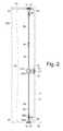
- FIG. 2is an elevation view showing the door latch of FIG. 1 from an exterior side of the door, with the door being shown in the closed configuration and with the door and the door frame indicated by hidden lines for purposes of clarity.
- FIG. 3is an enlarged, partial elevation view showing a portion of the door latch of FIG. 1 from an exterior side of the door, with the door being shown in the closed configuration and with the door and the door frame indicated by hidden lines and the exterior handset removed for purposes of clarity.
- FIG. 4is an enlarged, partial elevation view showing a portion of the door latch of FIG. 1 from an interior side of the door, with the door being shown in the closed configuration and with the door and the door frame indicated by broken lines and the interior handset removed for purposes of clarity.
- FIG. 5is an enlarged, partial side view showing a portion of the door latch of FIG. 1 from a hinge-side of the door, with the door frame and the door indicated by hidden lines for purposes of clarity.
- FIG. 1illustrates a door frame, indicated generally by reference character 10 , and a left-hand door, indicated generally by reference character 20 , with the door shown in an opened configuration.
- the door 20includes a three-way door latch, indicated generally by reference character 30 (see FIG. 2 ) constructed according to an exemplary embodiment of the present invention.
- the door frame 10 and the door 20are substantially of a conventional type with the exception of the modifications described herein necessary for operation in conjunction with the improved door latch 30 of the invention.
- the door frame 10comprises a latch-side vertical jamb 11 having a striker plate 12 and defining a recess (not visible in FIG. 1 ) for receiving a conventional sliding latch mounted within the door 20 in a known manner.
- the sliding latchhas a tapered, or beveled, end protruding outwardly from the door 20 and configured for engaging the striker plate 12 on the interior edge of the vertical jamb 11 of the door frame 10 while the door is being moved from the opened configuration to a closed configuration.
- the sliding latchis also commonly referred to as a striker plate latch.
- the sliding, or striker plate, latchcomprises an inner sleeve that is slidably disposed within a stationary outer housing.
- the inner sleeveis biased, for example by a linear spring positioned between the inner sleeve and the outer housing, such that the tapered, or beveled, end protrudes outwardly beyond the door 20 unless the inner sleeve is retracted into the outer housing against the biasing force exerted on the movable inner sleeve by the linear spring.
- a linear springpositioned between the inner sleeve and the outer housing, such that the tapered, or beveled, end protrudes outwardly beyond the door 20 unless the inner sleeve is retracted into the outer housing against the biasing force exerted on the movable inner sleeve by the linear spring.
- the recess defined by the vertical jamb 11 of the door frame 10is configured to receive a biased central latch 32 (see FIG. 2 ) of the door latch 30 when the door 20 is in the closed configuration.
- the door frame 10further comprises a horizontal lintel 13 having a striker plate 14 and defining a recess (not visible in FIG. 1 ).
- the recess defined by the horizontal lintel 13 of the door frame 10is configured to receive a biased upper latch 34 (see FIG. 2 ) of the door latch 30 when the door 20 is in the closed configuration.
- the door frame 10may further comprise a horizontal threshold, or sill, having a striker plate 16 and defining a recess (not visible in FIG. 1 ).
- the striker plate 16may be mounted on a floor 15 defining a recess for the striker plate 16 immediately beneath the striker plate 14 provided on the horizontal lintel 13 .
- the recess defined by the horizontal threshold or sill, or the floor 15is configured to receive a biased lower latch 36 (see FIG. 2 ) of the door latch 30 when the door 20 is in the closed configuration.
- Door frame 10further comprises a hinge-side vertical jamb that is hidden from view behind door 20 in FIG. 1 .
- the hinge-side vertical jambis provided with one or more hinge plates (not shown) operable for cooperating with corresponding hinges (not shown) mounted on the door 20 , such that the door pivots about the hinges relative to the door frame 10 between the opened configuration and the closed configuration in a well-known and conventional manner.
- the door 20comprises a latch-side vertical edge 21 having a guide plate 22 defining a through opening.
- the opening defined by the guide plate 22is configured to guide the protruding end (or deadbolt) 33 of the central latch 32 between a retracted, or unlatched, position wherein the protruding end does not engage with the door frame 10 , and an extended, or latched, position wherein the protruding end of the central latch frictionally engages with the door frame within the recess defined by the vertical jamb 11 .
- Door 20further comprises a horizontal top edge 23 having a guide plate 24 (not visible in FIG. 1 , see e.g., FIG.
- the opening defined by the guide plate 24is configured to guide the protruding end (or deadbolt) 35 of the upper latch 34 between a retracted, or unlatched, position wherein the protruding end does not engage with the door frame 10 , and an extended, or latched, position wherein the protruding end of the upper latch frictionally engages with the door frame within the recess defined by the lintel 13 .
- Door 20further comprises a horizontal bottom edge 25 having a guide plate 26 (not visible in FIG. 1 , see FIG. 2 ) defining a through opening.
- the opening defined by the guide plate 26is configured to guide the protruding end (or deadbolt) 37 of the lower latch 36 between a retracted, or unlatched, position wherein the protruding end does not engage with the door frame 10 , and an extended, or latched, position wherein the protruding end of the lower latch frictionally engages with the door frame within the recess defined by the threshold or sill, or floor 15 .
- the door 20further comprises an exterior handle, or handset, 27 A disposed on an exterior side 28 A of the door, and an interior handle, or handset 27 B disposed on an interior side 28 B of the door 20 that is hidden from view in FIG. 1 .
- the interior handset 27 Bmay be provided with a lock 29 A that is operable for preventing the exterior handset 27 A from being turned to unlatch the three-way door latch 30 and open the door 20 in a known manner.
- FIG. 2is an elevation view showing the door latch 30 in a locked or latched configuration as viewed from the exterior side 28 A of the door 20 .
- an exterior handset 27 Ais disposed on the exterior side 28 A of the door and an interior handset 27 B is disposed on the interior side 28 B of the door 20 , which is hidden from view in FIG. 2 .
- the exterior handset 27 Ais provided with a lock 29 A, for example a keyway configured for receiving a conventional mechanical key to lock the exterior handset against rotation in a known manner.
- the lock 29 Amay be configured for use with a magnetic key, a radiofrequency (RF) or an electronic key or other security reader. Regardless, the lock 29 A is operable for preventing a lock set 40 (see FIG. 3 , FIG. 4 ) disposed within the door 20 from being actuated by rotation of the exterior handset 27 A.
- the interior handset 27 Bmay likewise include a lock button 29 B (see FIG. 5 ) operable for preventing the exterior handset 27 A from being rotated to actuate the lock set 40 , and thereby release the plurality of door latches from engaging with the door frame 10 with the door 20 in the closed configuration.
- FIG. 2shows the door latch 30 comprises a plurality, and in particular, three separate door latches consisting of a central latch 32 , an upper latch 34 and a lower latch 36 .
- the door latches 32 , 34 , 36may be any type of door latch having a protruding end (or deadbolt) 33 , 35 , 37 that is configured to engage a corresponding recess provided in the door frame 10 in an extended (latched or locked) position, and is capable of being disengaged from the recess in a retracted (unlatched or unlocked) position, such that the door 20 can be moved from a closed configuration to an opened configuration.
- the protruding ends 33 , 35 , 37 of the latches 32 , 34 , 36may be biased towards the extended position, such that the protruding ends of the latches engage the corresponding recesses in the door frame 10 when the door 20 is in the closed configuration.
- at least the central latch 32alternatively may engage a recess, opening, slot or the like in another generally planar, hinged panel, for example another door adjacent to the door 20 to form a double door set in a known manner.
- lower actuating rod assembly 60 and lower sliding latch 36are configured essentially identical to and operate in essentially the same manner as upper actuating rod assembly 50 and upper sliding latch 34 .
- the latches 32 , 34 , 36 in the exemplary embodiment shown and described hereinare conventional sliding latches, also commonly referred to as striker plate latches.
- each sliding, or striker plate, latch 32 , 34 , 36comprises an inner sleeve 32 A, 34 A 36 A that is movably, and more particularly, slidably disposed within a stationary outer housing 32 B, 34 B, 36 B.
- the inner sleeveis biased outwardly by a biasing element 32 C (dashed line), 34 C, and the biasing element (not shown) of 36 , for example a linear spring, such that the protruding end 33 , 35 , 37 extends beyond the corresponding guide plate provided on the door 20 and the corresponding striker plate provided on the door frame 10 , unless and until the inner sleeve is retracted into the outer housing against the biasing force exerted on the inner sleeve by the biasing element.
- the central sliding latch 32is operably coupled with a lock set 40 to operate in a conventional manner.
- the lock set 40comprises a rotatable central shaft 42 that extends transversely through the thickness of the door 20 and is attached to the exterior handset 27 A disposed on the exterior side 28 A of the door and to the interior handset 27 B disposed on the interior side 28 B of the door.
- the shaft 42rotates with rotation of either the exterior handset 27 A or the interior handset 27 B, and in particular when either handset is turned. Rotation of the shaft 42 frictionally engages the inner sleeve 32 A of the central sliding latch 32 in a known manner to produce a lateral tension force that is greater than the biasing force exerted on the inner sleeve by the biasing element 32 C.
- upper sliding latch 34is coupled to lock set 40 by an upper actuating rod assembly 50 preferably comprising a vertical actuator rod 52
- lower sliding latch 36is coupled to lock set 40 by a lower actuating rod assembly 60 preferably comprising a vertical actuator rod 62
- at least upper actuating rod assembly 50includes an optional turnbuckle 54 for permitting gross adjustment of the length of actuator rod 52 between the lock set 40 and the upper sliding latch 34 to accommodate for differences in the distance between the medial through opening defined by the door 20 for receiving the lock set and the top edge 23 of the door.
- lower actuating rod assembly 60likewise may be provided with a turnbuckle (not shown) or the like for gross adjustment of the length of actuating rod 62 .
- lower actuating rod assembly 60 and lower sliding latch 36are configured essentially identical to and operate in essentially the same manner as upper actuating rod assembly 50 and upper sliding latch 34 . Accordingly, for purposes of brevity, only the configuration and the operation of the upper actuating rod assembly 50 and upper sliding latch 34 will be described in greater detail hereafter, it being understood that the configuration and operation of the lower actuating rod assembly 60 and the lower sliding latch 36 is essentially the same, except as indicated and in the opposing direction relative to lock set 40 .
- a cam 44is rotatably attached to the shaft 42 on one side, for example the interior side of the lock set 40 .
- rotation of the shaft 42results in simultaneous complete or incomplete rotation of the cam 44 .
- Rotation of cam 44in turn drives a generally L-shaped connecting arm 46 that is rigidly attached to an inner end 51 of the actuator rod 52 of upper actuating rod assembly 50 .
- lock set 40may be configured such that the reverse operation (i.e., either turning exterior handset 27 A in a counter clockwise direction or turning interior handset 27 B in a clockwise direction) likewise causes cam 44 to drive connecting arm 46 and actuator rod 52 in the vertically downward (or inward) direction. Regardless, operation of the lock set 40 , and specifically rotation of shaft 42 , results in downward vertical movement of actuator rod 52 relative to door 20 and door frame 10 .
- the opposite, outer end 53 of the actuator rod 52 of upper actuating rod assembly 50is attached to the movable inner sleeve of the upper sliding latch 34 .
- the outer end 53 of actuator rod 52may be provided with a clevis 56 that is pivotally attached to the inner sleeve 34 A of the upper sliding latch 34 by means of a transverse shaft, pin or the like 58 , such as a conventional cotter pin.
- fine adjustment of the position of the actuator rod 52 of the actuating rod assembly 50 relative to the position of the inner sleeve of the upper sliding latch 34may be accommodated by providing a threaded engagement between the outer end 53 of the actuator rod 52 and the clevis 56 .
- the vertically downward (or inward) movement of the actuator rod 52produces a vertical tension force that is greater than the biasing force exerted on the inner sleeve 34 A by the biasing element 34 C.
- rotation of the shaft 42 and cam 44 due to turning the exterior handset 27 A or the interior handset 27 Bresults in vertically downward (or inward) sliding movement of the inner sleeve 34 A relative to the outer housing 34 B, and consequently, movement of the protruding end 35 of the upper sliding latch 34 from its biased extended (latched or locked) position to a retracted (unlatched or unlocked) position.
- the configuration and operation of the lower actuating rod assembly 60 and the lower sliding latch 36is essentially the same as that of the upper actuating rod assembly 50 and the upper sliding latch 34 . Accordingly, turning the exterior handset 27 A or the interior handset 27 B causes simultaneous movement of the protruding end 37 of the lower sliding latch 36 from its biased extended (latched or locked) position to a retracted (unlatched or unlocked) position against the biasing force exerted on the inner sleeve 36 A by the biasing element (not shown) at lower sliding latch 36 .
- a single mechanical operation of turning the exterior handset 27 A or the interior handset 27 B in a clockwise direction or a counter clockwise directionsimultaneously retracts the protruding end (or deadbolt) 33 , 35 , 37 of the respective sliding latch 32 , 34 , 36 from the corresponding recess formed in the jamb 11 of the door frame 10 , the lintel 13 of the door frame, and the sill of the door frame or the floor 15 so that the door 20 may be moved from the closed configuration to the opened configuration.
- the exterior handset 27 A and the interior handset 27 Bare typically biased, for example by a torsion spring, towards a neutral position in which no inward lateral tension force is exerted on the inner sleeve 32 A of the central sliding latch 32 , and no inward vertical tension force is exerted on the inner sleeve 34 A of the upper sliding latch 34 and/or the inner sleeve 36 A of the lower sliding latch 36 .
- the inner sleeve 32 A, 34 A, 36 A of the respective sliding latch 32 , 34 , 36is biased outwardly relative to the outer housing 32 B, 34 B, 36 B by the corresponding biasing element 32 C, 34 C, and the biasing element (not shown) of 36 .
- the sliding latches 32 , 34 , 36retain the door in the closed configuration by frictional engagement of the protruding ends 33 , 35 , 37 of the respective sliding latches with the corresponding recesses formed in the door frame 10 or the floor 15 and/or by frictional engagement with the corresponding striker plates 12 , 14 , 16 .
- the sliding latches 32 , 34 , 36permit the door to be moved to the closed configuration by engagement of the protruding ends 33 , 35 , 37 of the respective sliding latches with the corresponding striker plates 12 , 14 , 16 to retract the protruding ends against the biasing force until the protruding ends are received within the corresponding recesses formed in the door frame 10 or the floor 15 .
- the foregoing detailed description of one or more exemplary embodiments of the present inventiondiscloses a latching or locking device, apparatus, system and method for retaining a generally planar panel in engagement with a stationary frame.
- the latching device, apparatus, system and methodis exemplified and embodied herein by a door latch for retaining a door to a door frame, another door or a floor at a plurality of locations adjacent a respective edge of the door.
- the door latchincludes a central latch that is biased towards an extended position and at least one of an upper latch that is biased towards an extended position and a lower latch biased that is towards an extended position.
- the door latchfurther includes a lock set operable for simultaneously moving the central latch and the at least one of the upper latch and the lower latch from the extended position to a retracted position.
- the door latchmay be provided with a locking element, member or the like configured to prevent turning of the exterior handset and the interior handset to operate the lock set, and thereby simultaneously retract the protruding end of each respective sliding latch to release the door from engagement with the door frame, floor or another door adjacent an edge of the door.
Landscapes
- Engineering & Computer Science (AREA)
- Mechanical Engineering (AREA)
- Structural Engineering (AREA)
- Wing Frames And Configurations (AREA)
Abstract
Description
Claims (1)
Priority Applications (1)
| Application Number | Priority Date | Filing Date | Title |
|---|---|---|---|
| US14/731,957US9428940B1 (en) | 2015-06-05 | 2015-06-05 | Three-way door latch |
Applications Claiming Priority (1)
| Application Number | Priority Date | Filing Date | Title |
|---|---|---|---|
| US14/731,957US9428940B1 (en) | 2015-06-05 | 2015-06-05 | Three-way door latch |
Publications (1)
| Publication Number | Publication Date |
|---|---|
| US9428940B1true US9428940B1 (en) | 2016-08-30 |
Family
ID=56739419
Family Applications (1)
| Application Number | Title | Priority Date | Filing Date |
|---|---|---|---|
| US14/731,957Expired - Fee RelatedUS9428940B1 (en) | 2015-06-05 | 2015-06-05 | Three-way door latch |
Country Status (1)
| Country | Link |
|---|---|
| US (1) | US9428940B1 (en) |
Cited By (17)
| Publication number | Priority date | Publication date | Assignee | Title |
|---|---|---|---|---|
| US20150330126A1 (en)* | 2012-12-21 | 2015-11-19 | Centor Design Pty Ltd | Latch mechanism |
| US20160245002A1 (en)* | 2015-02-23 | 2016-08-25 | Julian Michael Svenson | Locking post with an adjustable lock rod |
| US20170130494A1 (en)* | 2015-11-10 | 2017-05-11 | Caterpillar Inc. | Latch operating mechanism for cabin door |
| US20180273157A1 (en)* | 2017-03-21 | 2018-09-27 | Driessen Aerospace Group N.V. | Galley trolley compartment doors |
| US10246914B2 (en)* | 2012-03-21 | 2019-04-02 | Schlage Lock Company Llc | Two point lock for bi-fold windows and doors |
| US10876324B2 (en) | 2017-01-19 | 2020-12-29 | Endura Products, Llc | Multipoint lock |
| CN112647796A (en)* | 2020-12-24 | 2021-04-13 | 重庆北鑫机电有限公司 | Supporting structure and explosion-proof people's air defense emergency exit |
| US20210222473A1 (en)* | 2017-06-09 | 2021-07-22 | Endura Products, Llc | Sliding Door Unit and Components for the Same |
| US11111698B2 (en) | 2016-12-05 | 2021-09-07 | Endura Products, Llc | Multipoint lock |
| US20220403688A1 (en)* | 2018-08-13 | 2022-12-22 | Ron Zeitler | Door rod assembly |
| US11746565B2 (en) | 2019-05-01 | 2023-09-05 | Endura Products, Llc | Multipoint lock assembly for a swinging door panel |
| US20240110415A1 (en)* | 2022-03-29 | 2024-04-04 | Pella Corporation | Low profile multi-point lock drive |
| EP4477529A1 (en)* | 2023-06-16 | 2024-12-18 | The Boeing Company | Barrier door for an aircraft |
| US20250052098A1 (en)* | 2014-01-01 | 2025-02-13 | Brisbin Marvin Skiles | Locking system for doors and windows |
| US12264506B2 (en) | 2020-10-09 | 2025-04-01 | Assa Abloy Access And Egress Hardware Group, Inc. | Exit device rod adjustment |
| US12291351B2 (en) | 2023-06-16 | 2025-05-06 | The Boeing Company | Deployable attendant seat aircraft cabin barrier |
| US12312097B2 (en) | 2023-06-16 | 2025-05-27 | The Boeing Company | Hybrid barrier for aircraft cabin |
Citations (62)
| Publication number | Priority date | Publication date | Assignee | Title |
|---|---|---|---|---|
| US279334A (en) | 1883-06-12 | Door-bolt | ||
| US536957A (en)* | 1895-04-02 | Bernhard klein | ||
| US958880A (en) | 1909-06-21 | 1910-05-24 | Martin L Oberg | Lock. |
| US1075914A (en)* | 1913-02-17 | 1913-10-14 | Albertes Marion Hoes | Lock. |
| US1387573A (en)* | 1917-08-13 | 1921-08-16 | Joseph F Wilson | Lock-control for emergency exit-doors |
| US1596992A (en)* | 1924-10-16 | 1926-08-24 | Ognowicz Paul | Door-locking mechanism |
| US1646674A (en)* | 1926-05-03 | 1927-10-25 | Angelillo Fedele | Lock |
| US2069883A (en)* | 1935-07-02 | 1937-02-09 | Eastern Malleable Iron Company | Lock for the door of a refrigerator truck or car |
| US2169692A (en)* | 1938-03-14 | 1939-08-15 | Hansen Mfg Co A L | Door lock |
| US2202916A (en)* | 1938-08-03 | 1940-06-04 | Marcel V Mussa | Catch |
| US2597459A (en)* | 1949-04-11 | 1952-05-20 | Grand Rapids Hardware Company | Window balance |
| US2672745A (en)* | 1950-07-15 | 1954-03-23 | Marchetti Giovanni | Door lock |
| US2726109A (en)* | 1954-06-02 | 1955-12-06 | George T Bennett | Door stop |
| US2729089A (en)* | 1952-02-08 | 1956-01-03 | Eastern Malleable Iron Company | Solenoid-controlled door lock |
| US2735706A (en)* | 1956-02-21 | pelcin | ||
| US2793892A (en)* | 1955-04-04 | 1957-05-28 | Cummings Landau Laundry Machin | Latch mechanisms |
| US3086383A (en)* | 1960-07-22 | 1963-04-23 | Brasco Mfg Company | Two-way locking device |
| US3333878A (en)* | 1965-06-09 | 1967-08-01 | Eastern Co | Door control mechanism |
| US3362740A (en)* | 1964-10-13 | 1968-01-09 | Gen Motors Corp | Locking mechanism |
| US3433180A (en)* | 1966-07-06 | 1969-03-18 | Evans Prod Co | Freight bracing device |
| US3578369A (en)* | 1969-04-02 | 1971-05-11 | H B Ives Co The | Self-operating extension flush bolt |
| US3582122A (en)* | 1969-09-10 | 1971-06-01 | Von Duprin Inc | Automatic flush bolt |
| US3953061A (en)* | 1974-09-23 | 1976-04-27 | A. L. Hansen Mfg. Co. | Door fastening means |
| US4005886A (en)* | 1975-12-18 | 1977-02-01 | Door Controls Incorporated | Flush bolt mechanisms |
| US4227723A (en)* | 1977-09-16 | 1980-10-14 | Laperche | Multiple bolt latch |
| US4276760A (en)* | 1979-10-22 | 1981-07-07 | Nolin Roger J | Two-bolt lockset with simultaneous locking and unlocking of its bolts |
| US4362328A (en)* | 1980-05-19 | 1982-12-07 | Truth Incorporated | Patio door lock |
| US4387917A (en)* | 1979-12-26 | 1983-06-14 | Peter George Legg | Panic bolt units |
| US4445717A (en)* | 1981-05-18 | 1984-05-01 | Leigh Products, Inc. | Flush bolt |
| US4611840A (en)* | 1984-03-28 | 1986-09-16 | Martin Frank J | Door control mechanism |
| US4641865A (en)* | 1982-09-02 | 1987-02-10 | The Eastern Company | Closure control mechanism |
| US4934800A (en)* | 1989-05-18 | 1990-06-19 | Adams Rite Manufacturing Company | Low cost lever handle entry function |
| US5005881A (en)* | 1989-08-07 | 1991-04-09 | Rixson-Firemark Inc. | Door locking mechanism |
| US5076620A (en)* | 1988-08-01 | 1991-12-31 | Triangle Brass Manufacturing Company | Flush bolt mechanism for double doors |
| US5498038A (en)* | 1993-02-16 | 1996-03-12 | Marvin Lumber And Cedar Co. | Multi-point door lock system |
| US5590919A (en)* | 1995-01-17 | 1997-01-07 | Germano; John P. | T-astragal and sleeve for door |
| US5595076A (en)* | 1993-10-29 | 1997-01-21 | The Eastern Company | Handle operable two-point latch and lock |
| US5603534A (en)* | 1992-10-30 | 1997-02-18 | Fuller; Mark W. | Lock mechanism |
| US5782114A (en)* | 1995-01-13 | 1998-07-21 | Hoppe Ag | Multi-point locking system |
| US5813710A (en)* | 1997-04-08 | 1998-09-29 | Truth Hardware Corporation | Flush lock actuator |
| US5890753A (en)* | 1992-10-30 | 1999-04-06 | Fuller; Mark Weston | Lock mechanism |
| US5911763A (en) | 1998-01-12 | 1999-06-15 | Quesada; Flavio R. | Three point lock mechanism |
| US6120071A (en)* | 1999-01-22 | 2000-09-19 | Sargent Manufacturing Company | Mortise latch vertical rod exit device |
| US6217087B1 (en)* | 1994-12-07 | 2001-04-17 | Mark Weston Fuller | Lock mechanism |
| US6282929B1 (en)* | 2000-02-10 | 2001-09-04 | Sargent Manufacturing Company | Multipoint mortise lock |
| US6409231B1 (en)* | 1999-09-30 | 2002-06-25 | Architectural Builders Hardware Manufacturing Inc. | Flush bolt mechanism |
| US20020104339A1 (en)* | 2001-01-19 | 2002-08-08 | Roger Saner | Lock |
| US6923028B2 (en)* | 2003-10-16 | 2005-08-02 | William J. Caldwell | Locking system for a door |
| US7410195B1 (en)* | 2004-07-28 | 2008-08-12 | John C. Maynard, legal representative | Two-part automatic bolt for doors |
| US20090308112A1 (en)* | 2008-06-16 | 2009-12-17 | Adams Rite Manufacturing Co. | Multiple door locking control |
| US7712799B2 (en)* | 2007-12-03 | 2010-05-11 | Fu Chang Locks Mfg Corp. | Hidden lock locked to an inner side of a doorplate |
| US7752875B2 (en)* | 2003-09-22 | 2010-07-13 | Assa Abloy Australia Pty Limited | Multipoint lock |
| US7775564B2 (en)* | 2005-08-10 | 2010-08-17 | Compumeric Engineering, Inc. | Animal-resistant latching system |
| US8182002B2 (en) | 2006-10-03 | 2012-05-22 | W & F Manufacturing, Inc. | Multipoint door lock system with header and sill lock pins |
| US8191937B2 (en)* | 2009-04-09 | 2012-06-05 | Thase Enterprise Co. Ltd. | Automatic hidden latch structure |
| US20120139266A1 (en)* | 2010-12-06 | 2012-06-07 | Lynn Chiung-Ling Chen | Top-and-bottom latch structure for lock |
| US8555685B2 (en)* | 2009-10-05 | 2013-10-15 | George Frolov | Electrically controlled door lock |
| US8562032B1 (en)* | 2012-05-21 | 2013-10-22 | I-Tek Metal Mfg. Co., Ltd. | Latch assembly with automatic locking function |
| US20140026489A1 (en)* | 2012-05-18 | 2014-01-30 | Truth Hardware Corporation | Hardware for a hinged light panel |
| US8657345B1 (en)* | 2012-08-20 | 2014-02-25 | Feng-Ming SHIH | Safe linkage lockset |
| US8882162B2 (en)* | 2009-03-20 | 2014-11-11 | Hanchett Entry Systems, Inc. | Multiple point door locking system, with handle turning direction control |
| US8899635B2 (en)* | 2008-10-03 | 2014-12-02 | Truth Hardware Corporation | Sliding door multipoint mortise lock with shoot bolts |
- 2015
- 2015-06-05USUS14/731,957patent/US9428940B1/ennot_activeExpired - Fee Related
Patent Citations (64)
| Publication number | Priority date | Publication date | Assignee | Title |
|---|---|---|---|---|
| US2735706A (en)* | 1956-02-21 | pelcin | ||
| US536957A (en)* | 1895-04-02 | Bernhard klein | ||
| US279334A (en) | 1883-06-12 | Door-bolt | ||
| US958880A (en) | 1909-06-21 | 1910-05-24 | Martin L Oberg | Lock. |
| US1075914A (en)* | 1913-02-17 | 1913-10-14 | Albertes Marion Hoes | Lock. |
| US1387573A (en)* | 1917-08-13 | 1921-08-16 | Joseph F Wilson | Lock-control for emergency exit-doors |
| US1596992A (en)* | 1924-10-16 | 1926-08-24 | Ognowicz Paul | Door-locking mechanism |
| US1646674A (en)* | 1926-05-03 | 1927-10-25 | Angelillo Fedele | Lock |
| US2069883A (en)* | 1935-07-02 | 1937-02-09 | Eastern Malleable Iron Company | Lock for the door of a refrigerator truck or car |
| US2169692A (en)* | 1938-03-14 | 1939-08-15 | Hansen Mfg Co A L | Door lock |
| US2202916A (en)* | 1938-08-03 | 1940-06-04 | Marcel V Mussa | Catch |
| US2597459A (en)* | 1949-04-11 | 1952-05-20 | Grand Rapids Hardware Company | Window balance |
| US2672745A (en)* | 1950-07-15 | 1954-03-23 | Marchetti Giovanni | Door lock |
| US2729089A (en)* | 1952-02-08 | 1956-01-03 | Eastern Malleable Iron Company | Solenoid-controlled door lock |
| US2726109A (en)* | 1954-06-02 | 1955-12-06 | George T Bennett | Door stop |
| US2793892A (en)* | 1955-04-04 | 1957-05-28 | Cummings Landau Laundry Machin | Latch mechanisms |
| US3086383A (en)* | 1960-07-22 | 1963-04-23 | Brasco Mfg Company | Two-way locking device |
| US3362740A (en)* | 1964-10-13 | 1968-01-09 | Gen Motors Corp | Locking mechanism |
| US3333878A (en)* | 1965-06-09 | 1967-08-01 | Eastern Co | Door control mechanism |
| US3433180A (en)* | 1966-07-06 | 1969-03-18 | Evans Prod Co | Freight bracing device |
| US3578369A (en)* | 1969-04-02 | 1971-05-11 | H B Ives Co The | Self-operating extension flush bolt |
| US3582122A (en)* | 1969-09-10 | 1971-06-01 | Von Duprin Inc | Automatic flush bolt |
| US3953061A (en)* | 1974-09-23 | 1976-04-27 | A. L. Hansen Mfg. Co. | Door fastening means |
| US4005886A (en)* | 1975-12-18 | 1977-02-01 | Door Controls Incorporated | Flush bolt mechanisms |
| US4227723A (en)* | 1977-09-16 | 1980-10-14 | Laperche | Multiple bolt latch |
| US4276760A (en)* | 1979-10-22 | 1981-07-07 | Nolin Roger J | Two-bolt lockset with simultaneous locking and unlocking of its bolts |
| US4387917A (en)* | 1979-12-26 | 1983-06-14 | Peter George Legg | Panic bolt units |
| US4362328A (en)* | 1980-05-19 | 1982-12-07 | Truth Incorporated | Patio door lock |
| US4445717A (en)* | 1981-05-18 | 1984-05-01 | Leigh Products, Inc. | Flush bolt |
| US4641865A (en)* | 1982-09-02 | 1987-02-10 | The Eastern Company | Closure control mechanism |
| US4611840A (en)* | 1984-03-28 | 1986-09-16 | Martin Frank J | Door control mechanism |
| US5076620A (en)* | 1988-08-01 | 1991-12-31 | Triangle Brass Manufacturing Company | Flush bolt mechanism for double doors |
| US4934800A (en)* | 1989-05-18 | 1990-06-19 | Adams Rite Manufacturing Company | Low cost lever handle entry function |
| US5005881A (en)* | 1989-08-07 | 1991-04-09 | Rixson-Firemark Inc. | Door locking mechanism |
| US5603534A (en)* | 1992-10-30 | 1997-02-18 | Fuller; Mark W. | Lock mechanism |
| US5820173A (en)* | 1992-10-30 | 1998-10-13 | Fuller; Mark Weston | Lock mechanism |
| US5890753A (en)* | 1992-10-30 | 1999-04-06 | Fuller; Mark Weston | Lock mechanism |
| US5498038A (en)* | 1993-02-16 | 1996-03-12 | Marvin Lumber And Cedar Co. | Multi-point door lock system |
| US5595076A (en)* | 1993-10-29 | 1997-01-21 | The Eastern Company | Handle operable two-point latch and lock |
| US6217087B1 (en)* | 1994-12-07 | 2001-04-17 | Mark Weston Fuller | Lock mechanism |
| US5782114A (en)* | 1995-01-13 | 1998-07-21 | Hoppe Ag | Multi-point locking system |
| US5590919A (en)* | 1995-01-17 | 1997-01-07 | Germano; John P. | T-astragal and sleeve for door |
| US5813710A (en)* | 1997-04-08 | 1998-09-29 | Truth Hardware Corporation | Flush lock actuator |
| US5911763A (en) | 1998-01-12 | 1999-06-15 | Quesada; Flavio R. | Three point lock mechanism |
| US6120071A (en)* | 1999-01-22 | 2000-09-19 | Sargent Manufacturing Company | Mortise latch vertical rod exit device |
| US6409231B1 (en)* | 1999-09-30 | 2002-06-25 | Architectural Builders Hardware Manufacturing Inc. | Flush bolt mechanism |
| US6282929B1 (en)* | 2000-02-10 | 2001-09-04 | Sargent Manufacturing Company | Multipoint mortise lock |
| US20020104339A1 (en)* | 2001-01-19 | 2002-08-08 | Roger Saner | Lock |
| US7752875B2 (en)* | 2003-09-22 | 2010-07-13 | Assa Abloy Australia Pty Limited | Multipoint lock |
| US6923028B2 (en)* | 2003-10-16 | 2005-08-02 | William J. Caldwell | Locking system for a door |
| US7410195B1 (en)* | 2004-07-28 | 2008-08-12 | John C. Maynard, legal representative | Two-part automatic bolt for doors |
| US7775564B2 (en)* | 2005-08-10 | 2010-08-17 | Compumeric Engineering, Inc. | Animal-resistant latching system |
| US8182002B2 (en) | 2006-10-03 | 2012-05-22 | W & F Manufacturing, Inc. | Multipoint door lock system with header and sill lock pins |
| US7712799B2 (en)* | 2007-12-03 | 2010-05-11 | Fu Chang Locks Mfg Corp. | Hidden lock locked to an inner side of a doorplate |
| US20090308112A1 (en)* | 2008-06-16 | 2009-12-17 | Adams Rite Manufacturing Co. | Multiple door locking control |
| US8376415B2 (en)* | 2008-06-16 | 2013-02-19 | Adams Rite Manufacturing Co. | Multiple door locking control |
| US8899635B2 (en)* | 2008-10-03 | 2014-12-02 | Truth Hardware Corporation | Sliding door multipoint mortise lock with shoot bolts |
| US8882162B2 (en)* | 2009-03-20 | 2014-11-11 | Hanchett Entry Systems, Inc. | Multiple point door locking system, with handle turning direction control |
| US8191937B2 (en)* | 2009-04-09 | 2012-06-05 | Thase Enterprise Co. Ltd. | Automatic hidden latch structure |
| US8555685B2 (en)* | 2009-10-05 | 2013-10-15 | George Frolov | Electrically controlled door lock |
| US20120139266A1 (en)* | 2010-12-06 | 2012-06-07 | Lynn Chiung-Ling Chen | Top-and-bottom latch structure for lock |
| US20140026489A1 (en)* | 2012-05-18 | 2014-01-30 | Truth Hardware Corporation | Hardware for a hinged light panel |
| US8562032B1 (en)* | 2012-05-21 | 2013-10-22 | I-Tek Metal Mfg. Co., Ltd. | Latch assembly with automatic locking function |
| US8657345B1 (en)* | 2012-08-20 | 2014-02-25 | Feng-Ming SHIH | Safe linkage lockset |
Cited By (26)
| Publication number | Priority date | Publication date | Assignee | Title |
|---|---|---|---|---|
| US10246914B2 (en)* | 2012-03-21 | 2019-04-02 | Schlage Lock Company Llc | Two point lock for bi-fold windows and doors |
| US11927039B2 (en)* | 2012-12-21 | 2024-03-12 | Centor Design Pty Ltd. | Latch mechanism |
| US20150330126A1 (en)* | 2012-12-21 | 2015-11-19 | Centor Design Pty Ltd | Latch mechanism |
| US20250052098A1 (en)* | 2014-01-01 | 2025-02-13 | Brisbin Marvin Skiles | Locking system for doors and windows |
| US10107018B2 (en)* | 2015-02-23 | 2018-10-23 | Dynamic Closures Corporation | Locking post with an adjustable lock rod |
| US20160245002A1 (en)* | 2015-02-23 | 2016-08-25 | Julian Michael Svenson | Locking post with an adjustable lock rod |
| US20170130494A1 (en)* | 2015-11-10 | 2017-05-11 | Caterpillar Inc. | Latch operating mechanism for cabin door |
| US11111698B2 (en) | 2016-12-05 | 2021-09-07 | Endura Products, Llc | Multipoint lock |
| US12146344B2 (en) | 2017-01-19 | 2024-11-19 | Endura Products, Llc | Multipoint lock |
| US10876324B2 (en) | 2017-01-19 | 2020-12-29 | Endura Products, Llc | Multipoint lock |
| USD1026613S1 (en) | 2017-01-19 | 2024-05-14 | Endura Products, Llc | Locking device |
| US12104409B2 (en) | 2017-01-19 | 2024-10-01 | Endura Products, Llc | Multipoint lock |
| US10907390B2 (en)* | 2017-03-21 | 2021-02-02 | Safran Cabin Netherlands N.v. | Galley trolley compartment doors |
| US20180273157A1 (en)* | 2017-03-21 | 2018-09-27 | Driessen Aerospace Group N.V. | Galley trolley compartment doors |
| US12270236B2 (en)* | 2017-06-09 | 2025-04-08 | Endura Products, Llc | Sliding door unit and components for the same |
| US20210222473A1 (en)* | 2017-06-09 | 2021-07-22 | Endura Products, Llc | Sliding Door Unit and Components for the Same |
| US20220403688A1 (en)* | 2018-08-13 | 2022-12-22 | Ron Zeitler | Door rod assembly |
| US11746565B2 (en) | 2019-05-01 | 2023-09-05 | Endura Products, Llc | Multipoint lock assembly for a swinging door panel |
| US12331553B2 (en) | 2019-05-01 | 2025-06-17 | Endura Products, Llc | Multipoint lock assembly for a swinging door panel |
| US12264506B2 (en) | 2020-10-09 | 2025-04-01 | Assa Abloy Access And Egress Hardware Group, Inc. | Exit device rod adjustment |
| CN112647796A (en)* | 2020-12-24 | 2021-04-13 | 重庆北鑫机电有限公司 | Supporting structure and explosion-proof people's air defense emergency exit |
| US20240110415A1 (en)* | 2022-03-29 | 2024-04-04 | Pella Corporation | Low profile multi-point lock drive |
| EP4477529A1 (en)* | 2023-06-16 | 2024-12-18 | The Boeing Company | Barrier door for an aircraft |
| US12227282B2 (en) | 2023-06-16 | 2025-02-18 | The Boeing Company | Barrier door for an aircraft |
| US12291351B2 (en) | 2023-06-16 | 2025-05-06 | The Boeing Company | Deployable attendant seat aircraft cabin barrier |
| US12312097B2 (en) | 2023-06-16 | 2025-05-27 | The Boeing Company | Hybrid barrier for aircraft cabin |
Similar Documents
| Publication | Publication Date | Title |
|---|---|---|
| US9428940B1 (en) | Three-way door latch | |
| US7878034B2 (en) | Locking arrangement for a hinged panel | |
| CA2842361C (en) | Multi-point lock having sequentially-actuated locking elements | |
| CN104718339B (en) | Passive door latch mechanism | |
| US6971686B2 (en) | Multipoint lock system | |
| US20130200636A1 (en) | Handle-actuated locks | |
| US11851925B2 (en) | Key override for electromechanical multi-point latching device | |
| US20080196313A1 (en) | Door and Door Frame Assembly | |
| US20190242154A1 (en) | Anti-barricading turn hub assembly for a door lockset | |
| GB2122244A (en) | Multipoint side hung door lock | |
| GB2225052A (en) | Locking mechanism | |
| US5100184A (en) | Deadlatch assembly | |
| US10519692B1 (en) | Door latch | |
| US4031725A (en) | Door lock | |
| US11542726B2 (en) | Surface mounted single solenoid electric strike | |
| US11702864B2 (en) | Automatic locking-deadbolt assembly in a door | |
| GB2185059A (en) | Multiple latch mechanism | |
| CA2795998C (en) | Multiple access door lock mechanism with reversible cam actuation | |
| GB2215770A (en) | Improvements in or relating to locks | |
| EP2112305B1 (en) | Closure opening mechanism | |
| US20220235580A1 (en) | Lock assembly | |
| AU2012201867B2 (en) | Lock body | |
| EP3907355A1 (en) | Improved hook lock | |
| CN111868345B (en) | lock assembly | |
| EP2569497B1 (en) | Door having a device for openable latching of the door |
Legal Events
| Date | Code | Title | Description |
|---|---|---|---|
| ZAAA | Notice of allowance and fees due | Free format text:ORIGINAL CODE: NOA | |
| ZAAB | Notice of allowance mailed | Free format text:ORIGINAL CODE: MN/=. | |
| STCF | Information on status: patent grant | Free format text:PATENTED CASE | |
| AS | Assignment | Owner name:PATRICK & ALSTON, LLC, NORTH CAROLINA Free format text:ASSIGNMENT OF ASSIGNORS INTEREST;ASSIGNOR:PATRICK, CLARENCE;REEL/FRAME:049860/0466 Effective date:20190719 | |
| MAFP | Maintenance fee payment | Free format text:PAYMENT OF MAINTENANCE FEE, 4TH YEAR, MICRO ENTITY (ORIGINAL EVENT CODE: M3551); ENTITY STATUS OF PATENT OWNER: MICROENTITY Year of fee payment:4 | |
| FEPP | Fee payment procedure | Free format text:MAINTENANCE FEE REMINDER MAILED (ORIGINAL EVENT CODE: REM.); ENTITY STATUS OF PATENT OWNER: MICROENTITY | |
| LAPS | Lapse for failure to pay maintenance fees | Free format text:PATENT EXPIRED FOR FAILURE TO PAY MAINTENANCE FEES (ORIGINAL EVENT CODE: EXP.); ENTITY STATUS OF PATENT OWNER: MICROENTITY | |
| STCH | Information on status: patent discontinuation | Free format text:PATENT EXPIRED DUE TO NONPAYMENT OF MAINTENANCE FEES UNDER 37 CFR 1.362 | |
| FP | Lapsed due to failure to pay maintenance fee | Effective date:20240830 |