US9428118B1 - Retractable workstation integrated into the passenger cabin of a vehicle - Google Patents
Retractable workstation integrated into the passenger cabin of a vehicleDownload PDFInfo
- Publication number
- US9428118B1 US9428118B1US14/641,325US201514641325AUS9428118B1US 9428118 B1US9428118 B1US 9428118B1US 201514641325 AUS201514641325 AUS 201514641325AUS 9428118 B1US9428118 B1US 9428118B1
- Authority
- US
- United States
- Prior art keywords
- desktop
- workstation
- positioning system
- keyboard
- retracted position
- Prior art date
- Legal status (The legal status is an assumption and is not a legal conclusion. Google has not performed a legal analysis and makes no representation as to the accuracy of the status listed.)
- Active
Links
- 230000008878couplingEffects0.000description4
- 238000010168coupling processMethods0.000description4
- 238000005859coupling reactionMethods0.000description4
- 239000000463materialSubstances0.000description4
- 238000000034methodMethods0.000description4
- 230000000712assemblyEffects0.000description2
- 238000000429assemblyMethods0.000description2
- 230000008901benefitEffects0.000description2
- 238000004891communicationMethods0.000description2
- 238000005516engineering processMethods0.000description2
- 230000007774longtermEffects0.000description2
- 230000007246mechanismEffects0.000description2
- APTZNLHMIGJTEW-UHFFFAOYSA-Npyraflufen-ethylChemical compoundC1=C(Cl)C(OCC(=O)OCC)=CC(C=2C(=C(OC(F)F)N(C)N=2)Cl)=C1FAPTZNLHMIGJTEW-UHFFFAOYSA-N0.000description2
- 208000027418Wounds and injuryDiseases0.000description1
- 230000004913activationEffects0.000description1
- 230000006378damageEffects0.000description1
- 230000006870functionEffects0.000description1
- 230000005484gravityEffects0.000description1
- 208000014674injuryDiseases0.000description1
- 239000004973liquid crystal related substanceSubstances0.000description1
- 239000002184metalSubstances0.000description1
- 239000010409thin filmSubstances0.000description1
Images


Classifications
- B—PERFORMING OPERATIONS; TRANSPORTING
- B60—VEHICLES IN GENERAL
- B60R—VEHICLES, VEHICLE FITTINGS, OR VEHICLE PARTS, NOT OTHERWISE PROVIDED FOR
- B60R11/00—Arrangements for holding or mounting articles, not otherwise provided for
- B60R11/02—Arrangements for holding or mounting articles, not otherwise provided for for radio sets, television sets, telephones, or the like; Arrangement of controls thereof
- B60R11/0252—Arrangements for holding or mounting articles, not otherwise provided for for radio sets, television sets, telephones, or the like; Arrangement of controls thereof for personal computers, e.g. laptops, notebooks
- B—PERFORMING OPERATIONS; TRANSPORTING
- B60—VEHICLES IN GENERAL
- B60N—SEATS SPECIALLY ADAPTED FOR VEHICLES; VEHICLE PASSENGER ACCOMMODATION NOT OTHERWISE PROVIDED FOR
- B60N3/00—Arrangements or adaptations of other passenger fittings, not otherwise provided for
- B60N3/001—Arrangements or adaptations of other passenger fittings, not otherwise provided for of tables or trays
- B60N3/002—Arrangements or adaptations of other passenger fittings, not otherwise provided for of tables or trays of trays
- B—PERFORMING OPERATIONS; TRANSPORTING
- B60—VEHICLES IN GENERAL
- B60R—VEHICLES, VEHICLE FITTINGS, OR VEHICLE PARTS, NOT OTHERWISE PROVIDED FOR
- B60R11/00—Arrangements for holding or mounting articles, not otherwise provided for
- B60R11/02—Arrangements for holding or mounting articles, not otherwise provided for for radio sets, television sets, telephones, or the like; Arrangement of controls thereof
- B60R11/0264—Arrangements for holding or mounting articles, not otherwise provided for for radio sets, television sets, telephones, or the like; Arrangement of controls thereof for control means
- B—PERFORMING OPERATIONS; TRANSPORTING
- B60—VEHICLES IN GENERAL
- B60R—VEHICLES, VEHICLE FITTINGS, OR VEHICLE PARTS, NOT OTHERWISE PROVIDED FOR
- B60R11/00—Arrangements for holding or mounting articles, not otherwise provided for
- B60R2011/0001—Arrangements for holding or mounting articles, not otherwise provided for characterised by position
- B60R2011/0003—Arrangements for holding or mounting articles, not otherwise provided for characterised by position inside the vehicle
- B60R2011/0005—Dashboard
- B—PERFORMING OPERATIONS; TRANSPORTING
- B60—VEHICLES IN GENERAL
- B60R—VEHICLES, VEHICLE FITTINGS, OR VEHICLE PARTS, NOT OTHERWISE PROVIDED FOR
- B60R11/00—Arrangements for holding or mounting articles, not otherwise provided for
- B60R2011/0042—Arrangements for holding or mounting articles, not otherwise provided for characterised by mounting means
- B60R2011/008—Adjustable or movable supports
- B60R2011/0082—Adjustable or movable supports collapsible, e.g. for storing after use
- B—PERFORMING OPERATIONS; TRANSPORTING
- B60—VEHICLES IN GENERAL
- B60R—VEHICLES, VEHICLE FITTINGS, OR VEHICLE PARTS, NOT OTHERWISE PROVIDED FOR
- B60R11/00—Arrangements for holding or mounting articles, not otherwise provided for
- B60R2011/0042—Arrangements for holding or mounting articles, not otherwise provided for characterised by mounting means
- B60R2011/008—Adjustable or movable supports
- B60R2011/0084—Adjustable or movable supports with adjustment by linear movement in their operational position
- B—PERFORMING OPERATIONS; TRANSPORTING
- B60—VEHICLES IN GENERAL
- B60R—VEHICLES, VEHICLE FITTINGS, OR VEHICLE PARTS, NOT OTHERWISE PROVIDED FOR
- B60R11/00—Arrangements for holding or mounting articles, not otherwise provided for
- B60R2011/0042—Arrangements for holding or mounting articles, not otherwise provided for characterised by mounting means
- B60R2011/008—Adjustable or movable supports
- B60R2011/0092—Adjustable or movable supports with motorization
Definitions
- the present inventionrelates generally to vehicles and, more particularly, to a retractable workstation that is integrated into a vehicle's passenger cabin.
- laptop computerno longer requires that the user compromise on processor speed, display size, display resolution or memory. Additionally, given the battery life available in many such computers, the user is no longer required to limit their use to small working sessions. As a result, laptops have become a viable alternative for many professionals, offering the end user both the performance that they have come to expect from a desktop computer as well as the portability and convenience associated with a laptop. Unfortunately while the performance of laptop computers have improved dramatically over the last decade, their usefulness is still somewhat limited due to the settings in which they are often used. For example, in a car the user typically is required to rest their computer on their lap. This approach may be suitable for an extremely short task, such as responding to an email, but is not suited for extended tasks.
- the present inventionprovides a workstation that is mounted within the passenger cabin of a vehicle.
- the workstationis comprised of a desktop that is mounted to a guide assembly, the guide assembly being mounted within a portion of the dashboard located in front of the front row passenger seat.
- the desktopis movable via the guide assembly between a first, retracted position and a second, deployed position. When the desktop is in the first, retracted position, the desktop is stored completely within the dashboard. When the desktop is in the second, deployed position, the desktop extends into the passenger cabin in front of the passenger seat.
- the upper surface of the desktopmay include a ridge, where the ridge extends above the desktop surface, thus helping to prevent objects (e.g., a laptop) from sliding off of the desktop.
- the front edge region of the desktopmay be curved upward and away from the upper desktop surface, thus providing a lip that can be used to hold objects onto the desktop.
- the front surface of the desktopmay be coplanar with the outer surface of the dashboard.
- An adjustable locking hingemay be used to hingeably couple a rear portion of the desktop to the guide assembly.
- the workstationmay be further comprised of a rear desk portion that is hingeably coupled to the desktop.
- a displaymay be integrated into the rear desk portion, where the display is connectable to a source device by at least one of a wired connection and a wireless connection.
- the desktop and the rear desk portionWhen the desktop is in the first, retracted position the desktop and the rear desk portion may be in a closed position and then, when the desktop is in the second, deployed position the desktop and the rear desk portion may automatically open to an angle of at least 75 degrees.
- An adjustable locking hingemay be used to hingeably couple the rear desk portion to the desktop.
- a keyboardmay be integrated into a region of the desktop, where the keyboard is connectable to a source device by at least one of a wired connection and a wireless connection.
- a keyboardmay be hingeably coupled to an edge of the desktop, where the keyboard is connectable to a source device by at least one of a wired connection and a wireless connection.
- the desktopWhen the desktop is in the first, retracted position the desktop and the keyboard may be in a closed position. The keyboard is unfolded from the closed position prior to use and once the desktop has been moved to the second, deployed position.
- An adjustable locking hingemay be used to hingeably couple the keyboard to the edge of the desktop.
- a spring assemblymay be coupled to the workstation, where the spring assembly maintains tension on the desktop and forces the desktop from the first, retracted position towards the second, deployed position.
- the workstationmay further include a latch assembly that is operable by a workstation user. The latch assembly in the locked position maintains the desktop in the first, retracted position, while the latch assembly in the unlocked position allows the spring assembly to force the desktop from the first, retracted position towards the second, deployed position.
- a positioning system(e.g., an electro-mechanical or hydraulic positioning system) may be coupled to the workstation, where the positioning system is adjustable between a first position corresponding to the desktop in the first, retracted position and a second position corresponding to the desktop in the second, deployed position.
- the positioning systemmay further include a break-away link that is configured to break when a force greater than a preset force is applied to the desktop. When the break-away link breaks, the desktop is allowed to move from the second, deployed position towards the first, retracted position without aid from the positioning system.
- a workstation position selectoroperable by a workstation user, may be coupled to the positioning system, where the position selector in a first setting moves the positioning system to the first position, and where the position selector in a second setting moves the positioning system to the second position.
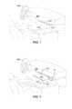
- FIG. 1provides a perspective view of an embodiment of the invention with the workstation shown in an early stage of extension from the dashboard;
- FIG. 2provides a perspective view of the embodiment of the workstation shown in FIG. 1 positioned in an intermediate stage of extension;
- FIG. 3provides a perspective view of the embodiment of the workstation shown in FIGS. 1 and 2 , positioned in the final, extended position in preparation for use;
- FIGS. 4A-4Cprovide a side view of the workstation shown in FIGS. 1-3 in the same three stages of extension;
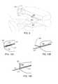
- FIGS. 5A-5Bprovide a side view of a workstation configuration in which the edge of the desktop is designed to blend into the dashboard when the workstation is in the closed position ( FIG. 5A ) and act as a desktop lip when the workstation is in the extended position ( FIG. 5B );
- FIG. 6provides a detailed perspective view of the workstation in an embodiment that includes both an integral keyboard and an integral display;
- FIGS. 7A-7Bprovide a side view of a workstation configuration which includes both an integral display and an integral keyboard, with FIG. 7A showing the workstation in the folded, closed position and FIG. 7B showing the workstation in the unfolded, extended position;
- FIG. 8provides a perspective view of an embodiment of the invention in which the workstation does not include a back portion, this view showing an initial stage of workstation deployment;
- FIG. 9provides a perspective view of the embodiment of the workstation shown in FIG. 8 , positioned in the final stage of deployment;
- FIGS. 10A-10Cprovide a side view of an embodiment in which the workstation guide tracks are set at an angle within the dashboard;
- FIGS. 11A-11Bprovide a side view of an embodiment utilizing a spring assembly deployment mechanism
- FIGS. 12A-12Bprovide a side view of an embodiment utilizing an automatic deployment mechanism.
- a first calculationcould be termed a second calculation, and, similarly, a first step could be termed a second step, and, similarly, a first component could be termed a second component, without departing from the scope of this disclosure.
- the present inventionprovides a retractable workstation that is mounted within the dashboard of a vehicle. In the retracted position the workstation is hidden from sight, while in the extended position it provides a convenient and ergonomic desk for use by the front seat passenger.
- the retractable workstationincludes a desktop and, in at least some embodiments, also includes a rear desk portion that may be used as an organizer to hold documents, e.g., as a bulletin board, or to support a computer display, e.g., a laptop display.
- the retractable workstationmay include an integrated display screen and/or an integrated keyboard.
- FIGS. 1-3illustrate a preferred embodiment of the invention, these views providing a perspective view of a two-piece workstation that includes a desktop portion 101 and a rear desk portion 103 .
- FIG. 1shows the workstation in an initial stage of extending out of a slot within dash 105 .
- FIG. 2shows the workstation partially open and in a further stage of extension.
- FIG. 3shows the workstation completely extended from the dash 105 , ready for use.
- the workstationhas completely opened, i.e., the angle between desktop portion 101 and rear desk portion 103 is at its maximum thereby allowing the desktop portion 101 to slant slightly downwards towards the passenger seat while the rear desk portion is now angling slightly away from the passenger seat.
- FIGS. 4A-4Cprovide a side view of these same three stages of workstation motion.
- an exemplary center console 107 and steering wheel 109is also visible in FIGS. 1-3 .
- the workstation of the inventioncan be configured in a variety of ways.
- the workstationincludes two portions, a desktop portion 101 and a rear portion 103 , that are hinged together at hinge 111 .
- hinge 111is a spring-loaded hinge that forces the two portions of the desktop to separate and angle away from one another to an angle of at least 75 degrees, and preferably to an angle of at least 90 degrees, and still more preferably to the maximum angle permissible by the hinge.
- this configurationincludes means, such as hydraulic dampers, to prevent the two portions of the workstation from opening too quickly.
- hinge 111is a user configurable hinge, e.g., an adjustable locking hinge that allows the user to set the relative angles of desktop portion 101 and rear desk portion 103 and then lock that setting to provide a stable workstation.
- the end portion section of desktop portion 101includes a lip 113 , this lip preventing a laptop or papers or other objects from sliding off of the edge of the desktop.
- the front face 501 of lip 113is designed to blend into dashboard 105 so that when the workstation is closed ( FIG. 5A ) the workstation is invisible and then when the workstation is extended ( FIG. 5B ) the lip 113 prevents objects from sliding off of the desktop.
- rear portion 103 of the workstationcan be configured to perform a variety of functions.
- rear portion 103is simply designed to provide a backdrop for a user-supplied display.
- the user-supplied displaymay be the display integrated into a laptop computer, a stand-alone display, a display attached to a portable DVD player, or other display.
- rear portion 103may include an integral display, either a touch screen or a non-touch screen, that uses any of a variety of display technologies (e.g., light-emitting diode (LED), plasma, organic light-emitting diode (OLED), liquid crystal (LCD), thin film transistor LCD (TFT-LCD), field emission display (FED) or other technology).
- display technologiese.g., light-emitting diode (LED), plasma, organic light-emitting diode (OLED), liquid crystal (LCD), thin film transistor LCD (TFT-LCD), field emission display (FED) or other technology.
- the workstationmay include cabling, for example hidden within a workstation compartment, or include a port 115 (e.g., Thunderbolt, USB, DVI, HDMI, DisplayPort, etc.) that allows the display to be coupled to a user source device (e.g., laptop, DVD player, etc.) with a separate cable.
- a sourcemay also be wirelessly connected to the integrated display using any of a variety of wireless communication protocols (e.g., IEEE 802.11, long term evolution (LTE), Wi-Fi, Bluetooth, WiGig, WirelessHD, etc.).
- the rear portion 103may be configured as a bulletin board, thus helping the user to remain organized while working at the workstation.
- the rear portion 103may include built-in clips or use an insert comprised of cork-board or a similar material that can be used to hold documents/materials in place, for example with push-pins.
- the insertmay also be comprised of metal that allows the user to use magnetic clips to organize their work.
- a keyboardis also integrated into the workstation.
- An example of an integrated keyboard 601is shown in FIG. 6 .
- keyboard 601is integrated into the lower portion of desktop 101 .
- the working area 603 of portion 101is separated from keyboard 601 by a small ridge 605 , ridge 605 preventing a laptop or other object placed on area 603 from sliding down onto keyboard 601 .
- keyboard 601is configured to allow it to wirelessly couple to a laptop or other device using any common wireless communication protocols (e.g., IEEE 802.11, long term evolution (LTE), Wi-Fi, Bluetooth, WiGig, WirelessHD, etc.).
- a USB, Thunderbolt or other port 607may be integrated into the workstation, thus allowing the user to connect to keyboard 601 using a cable.
- FIGS. 7A and 7Billustrate an alternate embodiment of a workstation that includes both an integrated display and keyboard.
- the keyboard 701is attached to desktop portion 101 by a hinge 703 .
- Hinge 703may be a spring-loaded hinge that forces the keyboard away from the desktop when the workstation is in the extended position (e.g., FIG. 7B ).
- a hydraulic damper or other meansmay be used to prevent the keyboard 701 from unfolding too quickly.
- hinge 703may be a user configurable hinge, e.g., an adjustable locking hinge, which allows the user to set and lock the angle of keyboard 701 relative to desktop portion 101 .
- hinge 703extends above the plane of desktop 101 , or includes a ridge that extends above the plane of desktop 101 , thus preventing a laptop or other object placed on the desktop from sliding off the desktop and onto the keyboard.
- keyboard 701may be coupled to a laptop or other device using either a wired or a wireless connection.
- FIGS. 8 and 9provide perspective views of an alternate embodiment of the workstation, these views showing an initial stage of workstation deployment ( FIG. 8 ) and a final, extended stage of workstation deployment ( FIG. 9 ).
- This embodimenteliminates the back portion 103 of the workstation and only provides a desktop.
- this embodimentis especially well suited for use with a laptop in which the user wants to utilize the laptop's display, or in an application in which the user simply needs a desktop to work.
- the edge 113 of desktop 101includes a ridge as previously described, thus helping to hold a laptop, documents, etc. on the desktop.
- a keyboardis included, where the keyboard is either attached via a hinge (e.g., FIGS. 7A-7B ) or integrated into the desktop surface (e.g., FIG. 6 ).
- Various coupling meanscan be interposed between the workstation and the internal structure of the dashboard, these coupling means allowing the workstation to smoothly deploy when needed, and then be easily placed into the storage position within the dash when not needed.
- Exemplary coupling meansinclude multi-link assemblies (e.g., a scissor linkage) and linkage assemblies that utilize telescopic links.
- the coupling meansincludes a pair of guide tracks 117 with one guide track subassembly mounted on either edge of the workstation. In one configuration the guide tracks 117 , and thus the workstation, are mounted horizontally within the dashboard 105 as shown in FIGS. 4A-4C . Alternately, the guide tracks and the workstation can be mounted at an angle within the dashboard as illustrated in FIGS.
- the procedures for deploying the workstation when needed, and then repositioning the workstation back into the dash when it is no longer neededcan be performed manually or using an electro-mechanical or hydraulic positioning system.
- a spring assembly 1101applies force on the rear portion of the workstation, or on a portion of the guide track assembly 117 .
- a latch assembly 1103keeps the workstation stored within dash 105 .
- she releases latch 1103thereby allowing the force of the spring assembly 1101 to deploy the workstation ( FIG. 11B ).
- Spring assembly 1101may be selected to insure that it is capable of supplying sufficient force to completely deploy the workstation. Alternately, the spring assembly may be designed to only partially deploy the workstation, requiring the user to complete deployment, for example by gripping the workstation (or gripping a handle or handles coupled to the workstation) and moving the workstation to the desired location. Once the workstation is no longer desired, preferably the user simply pushes the workstation back into the dash 105 until latch assembly 1103 locks the workstation into the storage position.
- a benefit of this embodimentis that when the workstation is in use, if it is accidently hit by the user, for example during a car collision, the spring assembly 1101 allows the workstation to be pushed back into the dash, thereby avoiding user injury.
- the workstation deployment systemutilizes a non-manual positioning system 1201 .
- positioning system 1201is an electro-mechanical (e.g., motorized) or hydraulic positioning system. In this configuration when the user activates the system, positioning system 1201 moves the workstation to the deployed position ( FIG. 12B ). When the workstation is no longer required, positioning system 1201 retracts the desk and stores it within dashboard 105 ( FIG. 12A ).
- a break-away linkis used with the positioning system so that if the user applies more than a preset level of force to the edge of the workstation, for example during a collision, the positioning system 1201 is de-coupled from the workstation and the workstation can be easily pushed back into the dashboard.
- the useris able to activate the positioning system 1201 in order to deploy or retract the workstation using any of a variety of control devices.
- dashboard 105or console 107 or the vehicle's headliner
- switches 1203e.g., push buttons
- a single switch 1203may be used that cycles the positioning system between workstation deployment and retraction.
- the activation switch(s)may also be incorporated into a touch screen user interface.
Landscapes
- Engineering & Computer Science (AREA)
- Mechanical Engineering (AREA)
- Transportation (AREA)
- Devices For Indicating Variable Information By Combining Individual Elements (AREA)
Abstract
Description
Claims (19)
Priority Applications (1)
| Application Number | Priority Date | Filing Date | Title |
|---|---|---|---|
| US14/641,325US9428118B1 (en) | 2015-03-07 | 2015-03-07 | Retractable workstation integrated into the passenger cabin of a vehicle |
Applications Claiming Priority (1)
| Application Number | Priority Date | Filing Date | Title |
|---|---|---|---|
| US14/641,325US9428118B1 (en) | 2015-03-07 | 2015-03-07 | Retractable workstation integrated into the passenger cabin of a vehicle |
Publications (2)
| Publication Number | Publication Date |
|---|---|
| US9428118B1true US9428118B1 (en) | 2016-08-30 |
| US20160257264A1 US20160257264A1 (en) | 2016-09-08 |
Family
ID=56739807
Family Applications (1)
| Application Number | Title | Priority Date | Filing Date |
|---|---|---|---|
| US14/641,325ActiveUS9428118B1 (en) | 2015-03-07 | 2015-03-07 | Retractable workstation integrated into the passenger cabin of a vehicle |
Country Status (1)
| Country | Link |
|---|---|
| US (1) | US9428118B1 (en) |
Cited By (26)
| Publication number | Priority date | Publication date | Assignee | Title |
|---|---|---|---|---|
| US20160251001A1 (en)* | 2015-02-26 | 2016-09-01 | William King | Vehicle lift system |
| CN106335443A (en)* | 2016-09-30 | 2017-01-18 | 北京汽车股份有限公司 | Multimedia system with switchable display scenes and car |
| US20170267184A1 (en)* | 2016-03-16 | 2017-09-21 | Ford Global Technologies, Llc | Multi-purpose storage compartment |
| US20180312094A1 (en)* | 2017-04-28 | 2018-11-01 | Faurecia Interieur Industrie | Trim element comprising a deployable part |
| USD843288S1 (en)* | 2016-08-30 | 2019-03-19 | Faraday&Future Inc. | Vehicle dashboard |
| US20190084609A1 (en)* | 2017-09-21 | 2019-03-21 | Ford Global Technologies, Llc | Steering assembly |
| US20190111785A1 (en)* | 2017-10-16 | 2019-04-18 | GM Global Technology Operations LLC | Multipurpose dashboard for use in a vehicle |
| CN110116681A (en)* | 2019-05-15 | 2019-08-13 | 湖南文理学院 | A kind of car-mounted computer Pop-up installation module of adjustable dismounting |
| US20200039562A1 (en)* | 2018-07-31 | 2020-02-06 | Steering Solutions Ip Holding Corporation | System and method of automatically stowing and unstowing a steering column assembly |
| US10737636B2 (en)* | 2018-01-31 | 2020-08-11 | Shanghai Yanfeng Jinqiao Automotive Trim Systems Co. Ltd. | Vehicle interior component |
| US20200298900A1 (en)* | 2019-03-20 | 2020-09-24 | Volvo Car Corporation | Vehicle having multiple driving positions |
| CN111791811A (en)* | 2020-06-29 | 2020-10-20 | 浙江安格鲁传动系统有限公司 | A flip-up interior trim panel and telescopic central control assembly |
| FR3096323A1 (en)* | 2019-05-21 | 2020-11-27 | Dav | Control interface for vehicle interior |
| US10906445B2 (en)* | 2018-04-12 | 2021-02-02 | Ford Global Technologies, Llc | Console-mounted deployable work surface |
| WO2021037841A1 (en)* | 2019-08-26 | 2021-03-04 | Brose Fahrzeugteile SE & Co. Kommanditgesellschaft, Coburg | Adjusting device for the adjusting of a two-dimensionally extended adjusting part in a vehicle interior |
| WO2021063809A1 (en)* | 2019-10-02 | 2021-04-08 | Daimler Ag | Table device and vehicle |
| US11084437B2 (en)* | 2016-12-12 | 2021-08-10 | Ford Global Technologies, Llc | Vehicle console with coupled motion and enhanced storage capabilities |
| CN114162017A (en)* | 2020-09-11 | 2022-03-11 | 现代摩比斯株式会社 | Vehicle workbench device and method for controlling virtual keyboard thereof |
| US11273747B1 (en)* | 2020-11-02 | 2022-03-15 | Ford Global Technologies, Llc | Multi-positional tray deployable from instrument panel |
| US20220080870A1 (en)* | 2020-09-11 | 2022-03-17 | Hyundai Mobis Co., Ltd. | Vehicle table device |
| US20230097623A1 (en)* | 2021-09-30 | 2023-03-30 | Ford Global Technologies, Llc | Deployable vehicle desk |
| US20230373371A1 (en)* | 2022-05-23 | 2023-11-23 | Claude M. Coache | Portable table system for mounting within a vehicle to provide a workspace within the vehicle |
| US20240059227A1 (en)* | 2020-12-08 | 2024-02-22 | Paul Hettich Gmbh & Co. Kg | Storage Element |
| US11932153B2 (en) | 2022-05-27 | 2024-03-19 | Ford Global Technologies, Llc | Vehicle having deployable sliding work desk |
| US12162393B2 (en) | 2022-07-25 | 2024-12-10 | Ford Global Technologies, Llc | Vehicle having deployable workstation |
| US20250242737A1 (en)* | 2024-01-29 | 2025-07-31 | Honda Motor Co., Ltd. | Pivotable system for vehicle dashboard to control vehicle foot space access |
Families Citing this family (1)
| Publication number | Priority date | Publication date | Assignee | Title |
|---|---|---|---|---|
| US11513754B2 (en) | 2020-09-08 | 2022-11-29 | Atieva, Inc. | Presenting content on separate display devices in vehicle instrument panel |
Citations (11)
| Publication number | Priority date | Publication date | Assignee | Title |
|---|---|---|---|---|
| US2845315A (en)* | 1957-03-18 | 1958-07-29 | Charles M Mccoy | Utility shelf for an automobile instrument panel |
| US3954315A (en)* | 1975-02-26 | 1976-05-04 | Sanden Edwin H | Cabinet drawer |
| US4368866A (en)* | 1980-06-27 | 1983-01-18 | International Jensen Incorporated | Mounting bracket and mounting arrangement |
| US5915776A (en)* | 1997-05-14 | 1999-06-29 | Reydel Societe Anonyme | Instrument panel for a vehicle |
| US20050018392A1 (en)* | 2001-05-23 | 2005-01-27 | Wolfgang Strohmeier | Retaining element for a portable computer device |
| US20060197353A1 (en)* | 2005-02-22 | 2006-09-07 | Hanzel Andrew J | Vehicle instrument panel having movable storage compartment |
| US20070262854A1 (en)* | 2006-05-09 | 2007-11-15 | Lockheed Martin Corporation | Tactical truck system dashboard |
| WO2008100216A1 (en)* | 2007-02-16 | 2008-08-21 | Scania Cv Ab (Publ) | Instrument panel |
| US20120049558A1 (en)* | 2009-06-30 | 2012-03-01 | Renault Sas | Device capable of providing a writing support in a motor vehicle and fascia panel comprising such a device |
| US20120250878A1 (en)* | 2011-03-25 | 2012-10-04 | Sony Corporation | In-vehicle audio apparatus |
| US20150343963A1 (en)* | 2014-05-28 | 2015-12-03 | Fca Italy S.P.A. | Vehicle dashboard provided with a supporting device for supporting a portable electronic device |
- 2015
- 2015-03-07USUS14/641,325patent/US9428118B1/enactiveActive
Patent Citations (11)
| Publication number | Priority date | Publication date | Assignee | Title |
|---|---|---|---|---|
| US2845315A (en)* | 1957-03-18 | 1958-07-29 | Charles M Mccoy | Utility shelf for an automobile instrument panel |
| US3954315A (en)* | 1975-02-26 | 1976-05-04 | Sanden Edwin H | Cabinet drawer |
| US4368866A (en)* | 1980-06-27 | 1983-01-18 | International Jensen Incorporated | Mounting bracket and mounting arrangement |
| US5915776A (en)* | 1997-05-14 | 1999-06-29 | Reydel Societe Anonyme | Instrument panel for a vehicle |
| US20050018392A1 (en)* | 2001-05-23 | 2005-01-27 | Wolfgang Strohmeier | Retaining element for a portable computer device |
| US20060197353A1 (en)* | 2005-02-22 | 2006-09-07 | Hanzel Andrew J | Vehicle instrument panel having movable storage compartment |
| US20070262854A1 (en)* | 2006-05-09 | 2007-11-15 | Lockheed Martin Corporation | Tactical truck system dashboard |
| WO2008100216A1 (en)* | 2007-02-16 | 2008-08-21 | Scania Cv Ab (Publ) | Instrument panel |
| US20120049558A1 (en)* | 2009-06-30 | 2012-03-01 | Renault Sas | Device capable of providing a writing support in a motor vehicle and fascia panel comprising such a device |
| US20120250878A1 (en)* | 2011-03-25 | 2012-10-04 | Sony Corporation | In-vehicle audio apparatus |
| US20150343963A1 (en)* | 2014-05-28 | 2015-12-03 | Fca Italy S.P.A. | Vehicle dashboard provided with a supporting device for supporting a portable electronic device |
Cited By (43)
| Publication number | Priority date | Publication date | Assignee | Title |
|---|---|---|---|---|
| US20160251001A1 (en)* | 2015-02-26 | 2016-09-01 | William King | Vehicle lift system |
| US9862327B2 (en)* | 2016-03-16 | 2018-01-09 | Ford Global Technologies Llc | Multi-purpose storage compartment |
| US20170267184A1 (en)* | 2016-03-16 | 2017-09-21 | Ford Global Technologies, Llc | Multi-purpose storage compartment |
| USD843288S1 (en)* | 2016-08-30 | 2019-03-19 | Faraday&Future Inc. | Vehicle dashboard |
| CN106335443B (en)* | 2016-09-30 | 2019-03-01 | 北京汽车股份有限公司 | A kind of multimedia system and automobile of changeable display scene |
| CN106335443A (en)* | 2016-09-30 | 2017-01-18 | 北京汽车股份有限公司 | Multimedia system with switchable display scenes and car |
| US11084437B2 (en)* | 2016-12-12 | 2021-08-10 | Ford Global Technologies, Llc | Vehicle console with coupled motion and enhanced storage capabilities |
| US20180312094A1 (en)* | 2017-04-28 | 2018-11-01 | Faurecia Interieur Industrie | Trim element comprising a deployable part |
| US10486576B2 (en)* | 2017-04-28 | 2019-11-26 | Faurecia Interieur Industrie | Trim element comprising a deployable part |
| US20190084609A1 (en)* | 2017-09-21 | 2019-03-21 | Ford Global Technologies, Llc | Steering assembly |
| US20190111785A1 (en)* | 2017-10-16 | 2019-04-18 | GM Global Technology Operations LLC | Multipurpose dashboard for use in a vehicle |
| US10583740B2 (en)* | 2017-10-16 | 2020-03-10 | Gm Global Technology Operations, Llc | Multipurpose dashboard for use in a vehicle |
| US10737636B2 (en)* | 2018-01-31 | 2020-08-11 | Shanghai Yanfeng Jinqiao Automotive Trim Systems Co. Ltd. | Vehicle interior component |
| US10906445B2 (en)* | 2018-04-12 | 2021-02-02 | Ford Global Technologies, Llc | Console-mounted deployable work surface |
| US11034377B2 (en)* | 2018-07-31 | 2021-06-15 | Steering Solutions Ip Holding Corporation | System and method of automatically stowing and unstowing a steering column assembly |
| US20200039562A1 (en)* | 2018-07-31 | 2020-02-06 | Steering Solutions Ip Holding Corporation | System and method of automatically stowing and unstowing a steering column assembly |
| US11801884B2 (en)* | 2019-03-20 | 2023-10-31 | Volvo Car Corporation | Vehicle having multiple driving positions |
| US20200298900A1 (en)* | 2019-03-20 | 2020-09-24 | Volvo Car Corporation | Vehicle having multiple driving positions |
| US20220185361A1 (en)* | 2019-03-20 | 2022-06-16 | Volvo Car Corporation | Vehicle having multiple driving positions |
| US11292504B2 (en)* | 2019-03-20 | 2022-04-05 | Volvo Car Corporation | Vehicle having multiple driving positions |
| CN110116681A (en)* | 2019-05-15 | 2019-08-13 | 湖南文理学院 | A kind of car-mounted computer Pop-up installation module of adjustable dismounting |
| FR3096323A1 (en)* | 2019-05-21 | 2020-11-27 | Dav | Control interface for vehicle interior |
| WO2021037841A1 (en)* | 2019-08-26 | 2021-03-04 | Brose Fahrzeugteile SE & Co. Kommanditgesellschaft, Coburg | Adjusting device for the adjusting of a two-dimensionally extended adjusting part in a vehicle interior |
| US12115894B2 (en) | 2019-10-02 | 2024-10-15 | Mercedes-Benz Group AG | Table device and vehicle |
| WO2021063809A1 (en)* | 2019-10-02 | 2021-04-08 | Daimler Ag | Table device and vehicle |
| CN114450194A (en)* | 2019-10-02 | 2022-05-06 | 梅赛德斯-奔驰集团股份公司 | Desk units and vehicles |
| CN111791811B (en)* | 2020-06-29 | 2023-09-26 | 浙江安格鲁传动系统有限公司 | A flip-up interior panel and telescopic central control assembly |
| CN111791811A (en)* | 2020-06-29 | 2020-10-20 | 浙江安格鲁传动系统有限公司 | A flip-up interior trim panel and telescopic central control assembly |
| US11590875B2 (en)* | 2020-09-11 | 2023-02-28 | Hyundai Mobis Co., Ltd. | Vehicle table device |
| CN114162017B (en)* | 2020-09-11 | 2023-12-26 | 现代摩比斯株式会社 | Vehicle table device and method for controlling virtual keyboard thereof |
| CN114162017A (en)* | 2020-09-11 | 2022-03-11 | 现代摩比斯株式会社 | Vehicle workbench device and method for controlling virtual keyboard thereof |
| US20220083218A1 (en)* | 2020-09-11 | 2022-03-17 | Hyundai Mobis Co., Ltd. | Vehicle table device and method of controlling virtual keyboard thereof |
| US11803300B2 (en)* | 2020-09-11 | 2023-10-31 | Hyundai Mobis Co., Ltd. | Vehicle table device and method of controlling virtual keyboard thereof |
| US20220080870A1 (en)* | 2020-09-11 | 2022-03-17 | Hyundai Mobis Co., Ltd. | Vehicle table device |
| US11273747B1 (en)* | 2020-11-02 | 2022-03-15 | Ford Global Technologies, Llc | Multi-positional tray deployable from instrument panel |
| US20240059227A1 (en)* | 2020-12-08 | 2024-02-22 | Paul Hettich Gmbh & Co. Kg | Storage Element |
| US11858399B2 (en)* | 2021-09-30 | 2024-01-02 | Ford Global Technologies, Llc | Deployable vehicle desk |
| US20230097623A1 (en)* | 2021-09-30 | 2023-03-30 | Ford Global Technologies, Llc | Deployable vehicle desk |
| US20230373371A1 (en)* | 2022-05-23 | 2023-11-23 | Claude M. Coache | Portable table system for mounting within a vehicle to provide a workspace within the vehicle |
| US12090906B2 (en)* | 2022-05-23 | 2024-09-17 | Claude M. Coache | Portable table system for mounting within a vehicle to provide a workspace within the vehicle |
| US11932153B2 (en) | 2022-05-27 | 2024-03-19 | Ford Global Technologies, Llc | Vehicle having deployable sliding work desk |
| US12162393B2 (en) | 2022-07-25 | 2024-12-10 | Ford Global Technologies, Llc | Vehicle having deployable workstation |
| US20250242737A1 (en)* | 2024-01-29 | 2025-07-31 | Honda Motor Co., Ltd. | Pivotable system for vehicle dashboard to control vehicle foot space access |
Also Published As
| Publication number | Publication date |
|---|---|
| US20160257264A1 (en) | 2016-09-08 |
Similar Documents
| Publication | Publication Date | Title |
|---|---|---|
| US9428118B1 (en) | Retractable workstation integrated into the passenger cabin of a vehicle | |
| US20160375924A1 (en) | Steering wheel with integrated keyboard assembly | |
| CN107787291B (en) | Deployable seat holder for portable electronic devices | |
| US10632889B2 (en) | Retractable table | |
| US8827341B2 (en) | Vehicle portable device holding system | |
| US9233649B2 (en) | Support and retention assembly for a portable electronic device, and dashboard provided with such a support and retention assembly | |
| CN204623328U (en) | Display positioning system | |
| US20150138448A1 (en) | Adjustable Display System for Vehicular Use | |
| CN108980538A (en) | Portable electronic device support component | |
| US10155483B2 (en) | Vehicle interior component | |
| JP6647291B2 (en) | Switch mechanism for electrically tuned screen mount | |
| EP3230162B1 (en) | Retractable device holder for an aircraft seat | |
| CN106740523A (en) | Mounting adaptation device | |
| US20080006754A1 (en) | Keyboard support | |
| US7126814B2 (en) | Space-saver design for personal computer keyboard | |
| US10017126B2 (en) | Actuator based extendable smartphone holding device of vehicle | |
| CN113492983B (en) | Cup holder assembly and table comprising same | |
| US20210039563A1 (en) | Mobile device holding system for a seat | |
| DE102015207378A1 (en) | Functionally variable vehicle interior system for a motor vehicle | |
| JP2020066262A (en) | Vehicle sun visor device | |
| US20240123907A1 (en) | Systems, methods, and devices for seat trays | |
| US9878801B2 (en) | Console assembly including stowable support surface | |
| CN210234851U (en) | Retaining device for retaining an article in a vehicle interior | |
| CN218907116U (en) | Holding device and decorative element | |
| JP2019156014A (en) | Vehicle sun visor device |
Legal Events
| Date | Code | Title | Description |
|---|---|---|---|
| AS | Assignment | Owner name:ATIEVA, INC., CALIFORNIA Free format text:ASSIGNMENT OF ASSIGNORS INTEREST;ASSIGNOR:RAWLINSON, PETER DORE;REEL/FRAME:035109/0333 Effective date:20150306 | |
| FEPP | Fee payment procedure | Free format text:PAYOR NUMBER ASSIGNED (ORIGINAL EVENT CODE: ASPN); ENTITY STATUS OF PATENT OWNER: SMALL ENTITY | |
| STCF | Information on status: patent grant | Free format text:PATENTED CASE | |
| AS | Assignment | Owner name:TRINITY CAPITAL FUND III, L. P., ARIZONA Free format text:INTELLECTUAL PROPERTY SECURITY AGREEMENT;ASSIGNOR:ATIEVA, INC;REEL/FRAME:042125/0897 Effective date:20170331 | |
| AS | Assignment | Owner name:YINLONG ELECTRIC VEHICLE (HK) GROUP LIMITED, HONG KONG Free format text:SECURITY INTEREST;ASSIGNORS:ATIEVA, INC.;ATIEVA USA, INC;REEL/FRAME:044457/0942 Effective date:20171027 Owner name:YINLONG ELECTRIC VEHICLE (HK) GROUP LIMITED, HONG Free format text:SECURITY INTEREST;ASSIGNORS:ATIEVA, INC.;ATIEVA USA, INC;REEL/FRAME:044457/0942 Effective date:20171027 | |
| AS | Assignment | Owner name:ATIEVA USA, INC., CALIFORNIA Free format text:RELEASE BY SECURED PARTY;ASSIGNOR:TRINITY CAPITAL FUND III, L.P.;REEL/FRAME:047529/0619 Effective date:20180912 Owner name:ATIEVA, INC., CAYMAN ISLANDS Free format text:RELEASE BY SECURED PARTY;ASSIGNOR:TRINITY CAPITAL FUND III, L.P.;REEL/FRAME:047529/0619 Effective date:20180912 Owner name:AVB METRICS, LLC, CALIFORNIA Free format text:RELEASE BY SECURED PARTY;ASSIGNOR:TRINITY CAPITAL FUND III, L.P.;REEL/FRAME:047529/0619 Effective date:20180912 | |
| AS | Assignment | Owner name:AVB METRICS, LLC, CALIFORNIA Free format text:RELEASE BY SECURED PARTY;ASSIGNOR:YINLONG ELECTRIC VEHICLE (HK) GROUP LIMITED;REEL/FRAME:047620/0451 Effective date:20180914 Owner name:ATIEVA, INC., CAYMAN ISLANDS Free format text:RELEASE BY SECURED PARTY;ASSIGNOR:YINLONG ELECTRIC VEHICLE (HK) GROUP LIMITED;REEL/FRAME:047620/0451 Effective date:20180914 Owner name:ATIEVA USA, INC., CALIFORNIA Free format text:RELEASE BY SECURED PARTY;ASSIGNOR:YINLONG ELECTRIC VEHICLE (HK) GROUP LIMITED;REEL/FRAME:047620/0451 Effective date:20180914 | |
| AS | Assignment | Owner name:AYAR THIRD INVESTMENT COMPANY, SAUDI ARABIA Free format text:SECURITY INTEREST;ASSIGNOR:ATIEVA, INC.;REEL/FRAME:047199/0221 Effective date:20180916 | |
| AS | Assignment | Owner name:ATIEVA, INC., CALIFORNIA Free format text:RELEASE BY SECURED PARTY;ASSIGNOR:AYAR THIRD INVESTMENT COMPANY;REEL/FRAME:048811/0472 Effective date:20190402 | |
| MAFP | Maintenance fee payment | Free format text:PAYMENT OF MAINTENANCE FEE, 4TH YR, SMALL ENTITY (ORIGINAL EVENT CODE: M2551); ENTITY STATUS OF PATENT OWNER: SMALL ENTITY Year of fee payment:4 | |
| FEPP | Fee payment procedure | Free format text:ENTITY STATUS SET TO UNDISCOUNTED (ORIGINAL EVENT CODE: BIG.); ENTITY STATUS OF PATENT OWNER: LARGE ENTITY | |
| MAFP | Maintenance fee payment | Free format text:PAYMENT OF MAINTENANCE FEE, 8TH YEAR, LARGE ENTITY (ORIGINAL EVENT CODE: M1552); ENTITY STATUS OF PATENT OWNER: LARGE ENTITY Year of fee payment:8 |