US9427935B2 - Thermoformable three dimensional retroreflective article and method of manufacture - Google Patents
Thermoformable three dimensional retroreflective article and method of manufactureDownload PDFInfo
- Publication number
- US9427935B2 US9427935B2US12/620,028US62002809AUS9427935B2US 9427935 B2US9427935 B2US 9427935B2US 62002809 AUS62002809 AUS 62002809AUS 9427935 B2US9427935 B2US 9427935B2
- Authority
- US
- United States
- Prior art keywords
- microbeads
- thermoformable
- protective sheet
- layer
- retroreflective
- Prior art date
- Legal status (The legal status is an assumption and is not a legal conclusion. Google has not performed a legal analysis and makes no representation as to the accuracy of the status listed.)
- Expired - Fee Related, expires
Links
Images


Classifications
- B—PERFORMING OPERATIONS; TRANSPORTING
- B32—LAYERED PRODUCTS
- B32B—LAYERED PRODUCTS, i.e. PRODUCTS BUILT-UP OF STRATA OF FLAT OR NON-FLAT, e.g. CELLULAR OR HONEYCOMB, FORM
- B32B5/00—Layered products characterised by the non- homogeneity or physical structure, i.e. comprising a fibrous, filamentary, particulate or foam layer; Layered products characterised by having a layer differing constitutionally or physically in different parts
- B32B5/16—Layered products characterised by the non- homogeneity or physical structure, i.e. comprising a fibrous, filamentary, particulate or foam layer; Layered products characterised by having a layer differing constitutionally or physically in different parts characterised by features of a layer formed of particles, e.g. chips, powder or granules
- B—PERFORMING OPERATIONS; TRANSPORTING
- B32—LAYERED PRODUCTS
- B32B—LAYERED PRODUCTS, i.e. PRODUCTS BUILT-UP OF STRATA OF FLAT OR NON-FLAT, e.g. CELLULAR OR HONEYCOMB, FORM
- B32B27/00—Layered products comprising a layer of synthetic resin
- B32B27/14—Layered products comprising a layer of synthetic resin next to a particulate layer
- B—PERFORMING OPERATIONS; TRANSPORTING
- B32—LAYERED PRODUCTS
- B32B—LAYERED PRODUCTS, i.e. PRODUCTS BUILT-UP OF STRATA OF FLAT OR NON-FLAT, e.g. CELLULAR OR HONEYCOMB, FORM
- B32B27/00—Layered products comprising a layer of synthetic resin
- B32B27/36—Layered products comprising a layer of synthetic resin comprising polyesters
- B—PERFORMING OPERATIONS; TRANSPORTING
- B32—LAYERED PRODUCTS
- B32B—LAYERED PRODUCTS, i.e. PRODUCTS BUILT-UP OF STRATA OF FLAT OR NON-FLAT, e.g. CELLULAR OR HONEYCOMB, FORM
- B32B3/00—Layered products comprising a layer with external or internal discontinuities or unevennesses, or a layer of non-planar shape; Layered products comprising a layer having particular features of form
- B32B3/02—Layered products comprising a layer with external or internal discontinuities or unevennesses, or a layer of non-planar shape; Layered products comprising a layer having particular features of form characterised by features of form at particular places, e.g. in edge regions
- B32B3/08—Layered products comprising a layer with external or internal discontinuities or unevennesses, or a layer of non-planar shape; Layered products comprising a layer having particular features of form characterised by features of form at particular places, e.g. in edge regions characterised by added members at particular parts
- B—PERFORMING OPERATIONS; TRANSPORTING
- B32—LAYERED PRODUCTS
- B32B—LAYERED PRODUCTS, i.e. PRODUCTS BUILT-UP OF STRATA OF FLAT OR NON-FLAT, e.g. CELLULAR OR HONEYCOMB, FORM
- B32B37/00—Methods or apparatus for laminating, e.g. by curing or by ultrasonic bonding
- B32B37/06—Methods or apparatus for laminating, e.g. by curing or by ultrasonic bonding characterised by the heating method
- B—PERFORMING OPERATIONS; TRANSPORTING
- B32—LAYERED PRODUCTS
- B32B—LAYERED PRODUCTS, i.e. PRODUCTS BUILT-UP OF STRATA OF FLAT OR NON-FLAT, e.g. CELLULAR OR HONEYCOMB, FORM
- B32B7/00—Layered products characterised by the relation between layers; Layered products characterised by the relative orientation of features between layers, or by the relative values of a measurable parameter between layers, i.e. products comprising layers having different physical, chemical or physicochemical properties; Layered products characterised by the interconnection of layers
- B32B7/04—Interconnection of layers
- B32B7/12—Interconnection of layers using interposed adhesives or interposed materials with bonding properties
- G—PHYSICS
- G02—OPTICS
- G02B—OPTICAL ELEMENTS, SYSTEMS OR APPARATUS
- G02B5/00—Optical elements other than lenses
- G02B5/12—Reflex reflectors
- G02B5/126—Reflex reflectors including curved refracting surface
- G02B5/128—Reflex reflectors including curved refracting surface transparent spheres being embedded in matrix
- B—PERFORMING OPERATIONS; TRANSPORTING
- B32—LAYERED PRODUCTS
- B32B—LAYERED PRODUCTS, i.e. PRODUCTS BUILT-UP OF STRATA OF FLAT OR NON-FLAT, e.g. CELLULAR OR HONEYCOMB, FORM
- B32B2255/00—Coating on the layer surface
- B32B2255/04—Coating on the layer surface on a particulate layer
- B—PERFORMING OPERATIONS; TRANSPORTING
- B32—LAYERED PRODUCTS
- B32B—LAYERED PRODUCTS, i.e. PRODUCTS BUILT-UP OF STRATA OF FLAT OR NON-FLAT, e.g. CELLULAR OR HONEYCOMB, FORM
- B32B2255/00—Coating on the layer surface
- B32B2255/20—Inorganic coating
- B32B2255/205—Metallic coating
- B—PERFORMING OPERATIONS; TRANSPORTING
- B32—LAYERED PRODUCTS
- B32B—LAYERED PRODUCTS, i.e. PRODUCTS BUILT-UP OF STRATA OF FLAT OR NON-FLAT, e.g. CELLULAR OR HONEYCOMB, FORM
- B32B2264/00—Composition or properties of particles which form a particulate layer or are present as additives
- B32B2264/10—Inorganic particles
- B32B2264/101—Glass
- B—PERFORMING OPERATIONS; TRANSPORTING
- B32—LAYERED PRODUCTS
- B32B—LAYERED PRODUCTS, i.e. PRODUCTS BUILT-UP OF STRATA OF FLAT OR NON-FLAT, e.g. CELLULAR OR HONEYCOMB, FORM
- B32B2264/00—Composition or properties of particles which form a particulate layer or are present as additives
- B32B2264/10—Inorganic particles
- B32B2264/107—Ceramic
- B—PERFORMING OPERATIONS; TRANSPORTING
- B32—LAYERED PRODUCTS
- B32B—LAYERED PRODUCTS, i.e. PRODUCTS BUILT-UP OF STRATA OF FLAT OR NON-FLAT, e.g. CELLULAR OR HONEYCOMB, FORM
- B32B2307/00—Properties of the layers or laminate
- B32B2307/40—Properties of the layers or laminate having particular optical properties
- B32B2307/402—Coloured
- B32B2307/4026—Coloured within the layer by addition of a colorant, e.g. pigments, dyes
- B—PERFORMING OPERATIONS; TRANSPORTING
- B32—LAYERED PRODUCTS
- B32B—LAYERED PRODUCTS, i.e. PRODUCTS BUILT-UP OF STRATA OF FLAT OR NON-FLAT, e.g. CELLULAR OR HONEYCOMB, FORM
- B32B2307/00—Properties of the layers or laminate
- B32B2307/40—Properties of the layers or laminate having particular optical properties
- B32B2307/412—Transparent
- B—PERFORMING OPERATIONS; TRANSPORTING
- B32—LAYERED PRODUCTS
- B32B—LAYERED PRODUCTS, i.e. PRODUCTS BUILT-UP OF STRATA OF FLAT OR NON-FLAT, e.g. CELLULAR OR HONEYCOMB, FORM
- B32B2307/00—Properties of the layers or laminate
- B32B2307/40—Properties of the layers or laminate having particular optical properties
- B32B2307/416—Reflective
- B—PERFORMING OPERATIONS; TRANSPORTING
- B32—LAYERED PRODUCTS
- B32B—LAYERED PRODUCTS, i.e. PRODUCTS BUILT-UP OF STRATA OF FLAT OR NON-FLAT, e.g. CELLULAR OR HONEYCOMB, FORM
- B32B2307/00—Properties of the layers or laminate
- B32B2307/40—Properties of the layers or laminate having particular optical properties
- B32B2307/422—Luminescent, fluorescent, phosphorescent
- B—PERFORMING OPERATIONS; TRANSPORTING
- B32—LAYERED PRODUCTS
- B32B—LAYERED PRODUCTS, i.e. PRODUCTS BUILT-UP OF STRATA OF FLAT OR NON-FLAT, e.g. CELLULAR OR HONEYCOMB, FORM
- B32B2437/00—Clothing
- B—PERFORMING OPERATIONS; TRANSPORTING
- B32—LAYERED PRODUCTS
- B32B—LAYERED PRODUCTS, i.e. PRODUCTS BUILT-UP OF STRATA OF FLAT OR NON-FLAT, e.g. CELLULAR OR HONEYCOMB, FORM
- B32B2590/00—Signboards, advertising panels, road signs
- B—PERFORMING OPERATIONS; TRANSPORTING
- B32—LAYERED PRODUCTS
- B32B—LAYERED PRODUCTS, i.e. PRODUCTS BUILT-UP OF STRATA OF FLAT OR NON-FLAT, e.g. CELLULAR OR HONEYCOMB, FORM
- B32B2605/00—Vehicles
- B32B2605/08—Cars
- Y—GENERAL TAGGING OF NEW TECHNOLOGICAL DEVELOPMENTS; GENERAL TAGGING OF CROSS-SECTIONAL TECHNOLOGIES SPANNING OVER SEVERAL SECTIONS OF THE IPC; TECHNICAL SUBJECTS COVERED BY FORMER USPC CROSS-REFERENCE ART COLLECTIONS [XRACs] AND DIGESTS
- Y10—TECHNICAL SUBJECTS COVERED BY FORMER USPC
- Y10T—TECHNICAL SUBJECTS COVERED BY FORMER US CLASSIFICATION
- Y10T428/00—Stock material or miscellaneous articles
- Y10T428/24—Structurally defined web or sheet [e.g., overall dimension, etc.]
- Y10T428/24355—Continuous and nonuniform or irregular surface on layer or component [e.g., roofing, etc.]
- Y10T428/24364—Continuous and nonuniform or irregular surface on layer or component [e.g., roofing, etc.] with transparent or protective coating
Definitions
- This inventiongenerally relates to articles made from thermoformable retroreflective sheet materials, and is specifically concerned with three dimensional retroreflective articles formed from thermoformable materials that include an outer surface with a reflectivity of at least about 200, and method for making such an article from a thermoformable laminate.
- Retroreflective articles employing an outer layer of microbeadsare known in the prior art.
- a bead-containing coatingis applied over the outer surface of the article (which may be, for example, protective helmet).
- the coatingis allowed to dry, and is then etched to expose the microbeads.
- a transparent sheet of vinyl chloride or other polymeric materialis molded into the same shape as the article, and mounted over the outside surface, advantageously encapsulating them while leaving a small air space between the transparent material and the tops of the microbeads.
- Such encapsulationboth protects the beads and prevents direct contact between the beads and ambient moisture, which could interfere with their retroreflective properties.
- a flexible, microbead-containing sheet materialis applied over the outer surface of the article.
- Such sheet materialsare known which have a sufficient amount of stretch to allow them to be evenly adhered over the surfaces of embossed license plates, road cones and road markers.
- a microbead containing, non-woven fabricis used to make retroreflective vests and other garments for highway workers working at night.
- the inventionis both a three dimensional (substantially non-planar) retroreflective article, a laminate and method for making such an article having an outer surface with a reflectivity of at least about 200 lux that overcomes the aforementioned shortcomings associated with the prior art.
- a principle aspect of the inventionstems from the applicant's observation that the thermoforming of an encapsulated microbead retroreflective sheet material, under certain conditions, can produce a three dimensional article of virtually any shape with a high reflectivity of about 200-300 lux.
- thermoformable microbead laminatewould cause the encapsulating layer to fuse over the tops of the microbeads, thereby fatally destroying the necessary airspace between the microbeads and the encapsulating layer and creating reflection-degrading “dead spots” over the tops of the microbeads which would make it impossible to achieve high-intensity retroreflectivity.
- the retroreflective three dimensional article of the inventioncomprises a laminate formed from a base or first layer of thermoformable plastic sheet material, the first layer having first and second sides; a layer of retroreflective microbeads adhered to an outer surface or first side of said base material by a thermoformable cushion coat, and a protective sheet or second layer of transparent thermoformable sheet material overlying the layer of microbeads, where there is some variation in the diameter of the microbeads.
- the laminateis thermoformed into a self supporting three dimensional article, which is generally non-planar, having a pre-selected shape and an encapsulated bead retroreflective surface having a reflectivity of at least about 200 lux.
- the protective sheetmay be in contact with some of the microbeads, and may be colored.
- the microbeadsare configured in a high-density arrangement and are silvered on their bottom sides to provide high-intensity retroreflection.
- the cushion coatmay include a phosphorescent pigment to further enhance reflectivity, and is preferably a layer of binder containing a polyvinyl copolymer, a thermoplastic polyurethane, and an aminoplast resin.
- the transparent layerpreferably has a thickness of between about 4-8 times an average diameter of the microbeads, and the base layer preferably has a thickness of between about 4 to 12 times an average diameter of the microbeads.
- Both the protective transparent layer and the base layermay be formed from a thermoformable plastic material such as PETG (glycol-modified polyethylene terephthalate).
- PETGglycol-modified polyethylene terephthalate
- the use of PETG as the protective transparent layeradvantageously results in some degree of “pull back” from the microbeads upon cooling after thermoforming
- the use of variable diameter microbeadslimits fusing contact between the protective transparent layer and only the largest diameter microbeads.
- the surface of the three dimensional articlepreferably is sufficiently non-planar so that retroreflective dead spots created by limited amount of contact between the microbeads and the protective sheet of transparent sheet material are effectively optically cancelled by overlapping zones of retroreflectivity generated by the microbeads.
- the method of the inventiongenerally comprise the steps of adhering, via aforementioned cushion coat, a plurality of retroreflective, semi-silvered microbeads in a high-density arrangement onto the base layer of thermoformable plastic sheet material; overlying the protective sheet of transparent, thermoformable sheet material in contact with the retroreflective microbeads adhered to the base layer to form a generally flat combination layer; applying sufficient heat to the combination layer to render it thermoformable, and thermoforming the heated combination layer into a three dimensional article having a pre-selected shape and an encapsulated bead retroreflective surface having a reflectivity of at least about 200 lux.
- thermoforming stepimparts sufficient non-planarity in the resulting retroreflective surface so that retroreflective dead spots created by contact between the microbeads and the protective sheet of transparent sheet material are effectively optically cancelled by overlapping zones of retroreflectivity generated by the microbeads.
- FIG. 1illustrates the first step in the method of assembling the thermoformable laminate of the invention, wherein microbeads are adhered in a dense arrangement and randomly distributed over a donor sheet consisting of layer of adhesive overlying a support layer of polyethylene terephthalate;
- FIG. 2illustrates the step of metallizing the bottom halves of the microbeads on the donor sheet
- FIG. 3illustrates the step of applying an adhesive cushion coat over a removable substrate
- FIG. 4illustrates the step of adhering a thermoformable support sheet over the exposed surface of the cushion coat and peeling off the removable substrate
- FIG. 5illustrates the step of pressing the thermoformable support sheet and the exposed surface of the adhesive cushion coat onto the layer of metallized beads on the top surface of the donor sheet;
- FIG. 6illustrates how the adhesive cushion coat removes the layer of metallized beads from the donor sheet
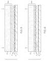
- FIG. 7illustrates the laminate resulting from the step illustrated in FIG. 6 ;
- FIG. 8illustrates the final step of assembling the thermoformable laminate of the invention, wherein a protective sheet of thermoformable, transparent sheet material is positioned over the microbeads adhered over the substrate of thermoformable plastic material;
- FIG. 9is an enlargement of the area circled in phantom in FIG. 7 and illustrates how the natural variation in the diameter of the microbeads causes only some of the microbeads to tangentially contact the underside of the transparent protective sheet material prior to thermoforming;
- FIG. 10illustrates how the softening of the protective, transparent sheet material during thermoforming of the laminate causes the sheet to sag and fusingly contact the top ends of the microbeads
- FIG. 11illustrates how the transparent, protective sheet material shown in FIG. 10 “pulls back” out of contact with many of the microbeads after cooling, thereby leaving most of the microbeads with an air space between the transparent protective sheet and the tops of the microbeads, and
- FIG. 12illustrates how a three dimensional helmet shell thermoformed from the laminate illustrated in FIG. 11 is rapidly assembled over a conventional construction safety helmet to render it brightly retroreflective.
- FIGS. 1 and 2illustrate the first steps in fabricating the thermoformable laminate used in the method of making the high intensity retroreflective article of the invention.
- a bead donor sheet 1is prepared by adhering a 1 mil thick sheet 3 of low density polyethylene over a 3 mil thick layer of a substrate 5 , which in this example is a sheet of polyethylene terephthalate.
- Heatis next applied to the resulting bead donor sheet 1 via a heat source (not shown) in order to soften the 1 mil thick sheet 3 of low density polyethylene.
- the substrate 5having a higher melting point, is able to support the softened sheet 3 throughout this step.
- Glass or ceramic microbeads 6are next applied over the softened sheet 3 .
- the microbeads 6have an average diameter of between about 40 and 90 microns, with a variation of ⁇ 15%.
- the range of diameterswould vary between 42.5 microns to 57.5 microns.
- such a variation in diameteradvantageously creates air spaces between most of the microbeads and the transparent protective sheet that ultimately forms the top layer of the resulting thermoformable laminate.
- the beads 6are applied over the heat-softened, 1 mil thick sheet 3 of low density polyethylene in a high-density arrangement where the beads 6 , on average, are practically touching one another.
- the microbeads 6sink into the heat softened sheet 3 until their bottom halves are at least partially embedded into the low density polyethylene forming the sheet 3 .
- the heat sourceis removed in order to allow the donor sheet 1 to cool and the 1 mil thick sheet 3 of low density polyethylene to harden, which in turn weakly adheres the microbeads 7 to the donor sheet 1 .
- the exposed hemispheres of the beads 6are metallized by the application of a thin layer 9 on the order of 300 nanometers of vapor-deposited aluminum. This step results in a bead donor sheet 1 having a high density layer 8 of semi-metallized microbeads 7 weakly adhered to the sheet 3 of low density polyethylene.
- an adhesive cushion coat 11is applied to a thermoformable support sheet 15 , as illustrated in FIGS. 3 and 4 .
- Thisis accomplished by first applying a cushion coat 11 over a 2 mil thick sheet 13 of polyethylene terephthalate, as schematically illustrated in FIG. 3 .
- the cushion coat 11is formed from a layer of white pigmented binder containing a polyvinyl copolymer, a thermoplastic polyurethane, and an aminoplast resin as disclosed in Levenstein U.S. Pat. No. 6,586,067, and assigned to the Avery Dennison Corporation the common assignee of the instant application.
- the thickness of the cushion coat 11is approximately 2 ⁇ 3 the average diameter of the beads, or about 2 mils.
- the cushion coatmay include a phosphorescent pigment.
- the exposed face of the cushion coat 11is next heat laminated to a thermoformable support sheet 15 , as schematically indicated in FIG. 4 .
- support sheet 15is a 20-30 mil thick sheet of glycol-modified polyethylene terephthalate, although other thermoformable plastic materials may also be used.
- the 2 mil thick sheet 13 of polyethylene terephthalateis peeled off of the cushion coat 11 , as is also indicated in FIG. 4 .
- FIGS. 5 and 6illustrate how the bead donor sheet 1 of FIG. 2 and the sub-laminate 16 a of FIG. 4 are brought together to form a beaded sub-laminate 16 b formed from the layer 8 of semi-metallized microbeads 7 , the cushion coat 11 , and the support sheet 15 .
- the exposed side of the cushion coat 11is positioned over the layer 8 of semi-metallized microbeads 7 overlying the donor sheet 1 and is pressed into contact so that the cushion coat 11 adheres to the metallized hemispheres of the beads 7 , as indicated in FIG. 5 .
- the support sheet 15 and cushion coat 11is lifted off of the face of the donor sheet 1 , as is indicated in FIG. 6 .
- the layer 8 of semi-metallized microbeadsis lifted off of the donor sheet, forming a beaded sub-laminate 16 b.
- FIGS. 7 and 8illustrate the final steps in forming the laminate used in fabricating the high-intensity retroreflective articles of the invention.
- the beaded sub-laminate 16 b or combination layer formed in the step illustrated in FIG. 6is removed from the donor sheet 1 and righted into the position illustrated in FIG. 7 .
- a thermoformable, transparent sheet material 17is positioned over the sub-laminate 16 b to form the thermoformable laminate 18 used to fabricate the three dimensional articles of the invention. While the sheet material 17 is preferably transparent, it may be colored or tinted as desired to give the final article formed from the laminate 18 a desired color or appearance.
- the sheet material 17may possess a color-neutral transparency and a desired coloring of the final article may be achieved by the inclusion of a coloring pigment (either phosphorescent or otherwise) in the cushion coat 11 .
- the transparent sheet material 17may be placed over the beaded sub-laminate 16 b either before, after, or at the time of the thermoforming of the beaded sub-laminate 16 b into a three dimensional article.
- transparent sheet material 17is a 20-30 mil thick sheet of glycol-modified polyethylene terephthalate, as such a plastic would have substantially the same thermoforming characteristics as the support sheet 15 (which is also formed from glycol-modified polyethylene terephthalate) and would have sufficient thickness to both protect the bead layer 8 and to contribute to the desired, self-supporting rigidity of the final thermoformed article.
- FIGS. 9, 10 and 11illustrate how the laminate 18 of the invention advantageously maintains its high intensity retroreflective optical characteristics through the process of thermoforming the laminate into a three dimensional article.
- FIG. 9is an enlargement of the area circled in phantom shown by reference numeral 9 in FIG. 8 , and illustrates in particular the interface between the tops of the bead 7 and the lower surface 19 of the transparent protective sheet 17 . Due to the natural variation in the diameter of the beads 7 , as well as variations in the depth “D” that these beads extend into the cushion coat 11 , there are variations in the relative height “H” in the beads 7 .
- the only contact between the transparent protective sheet 17 and the beads 7is tangential point contact 20 between the lower surface 19 and the tops of only the highest beads 7 .
- Such contactadvantageously leaves air spaces 21 a , 21 b and 21 c of varying widths between the tops of the other beads and the lower surface 19 of the transparent protective sheet 17 which in turn allows the microbeads 7 to operate at maximum retroreflectivity with only a small number of narrow-angle “dead spots” caused by the infrequent tangential point contact 20 between the microbeads 7 and the lower surface 19 of the transparent protective sheet 17 .
- FIG. 10illustrates how the interface between the lower surface 19 and the tops of the microbeads 7 changes when the transparent protective sheet 17 is heat-softened incident to the thermoforming of the laminate 18 into a three dimensional article.
- heat softening of the sheet 17occurs simultaneously with the heat softening of the sub-laminate 16 b in order to minimize the amount of time, steps and power necessary to thermoform a three dimensional article of the invention.
- the transparent protective sheet 17may be separately thermoformed over an article thermoformed from the sub-laminate 16 b .
- FIG. 10is applicable to both variations in the method of the invention, and illustrates how the softening and drawing down of the transparent protective sheet 17 over the tops of the microbeads 7 broadens the interface between the lower surface 19 and the microbeads to areas 23 a , 23 b and 23 c of fusing contact of varying sizes, such areas being largest ( 23 a ) between the highest microbeads and smaller ( 23 b and 23 c ) with lower microbeads, but nonexistent between the lowest microbeads 7 and the lower surface 19 (note air space 21 b ).
- FIG. 11illustrates how the specific thicknesses and composition of the transparent protective sheet 17 eliminates much of the fusing contact between the microbeads 7 and the lower surface 19 when the transparent protective sheet 17 is allowed to cool after a thermoforming operation.
- the applicanthas found that the thermal contraction of a transparent protective sheet of the aforementioned composition and thickness range results in “pull back” of the lower surface 19 from the tops of the microbeads that either eliminates or at least substantially reduces the resulting final amount of contact between the lower surface 19 and the microbeads 7 such that an air space 21 a , 21 b is restored between the surface 19 and about half or more of the microbeads.
- FIG. 12illustrates a practical application of a high retroreflectivity, three dimensional article in the form of an outer hard hat shell 27 .
- shell 27is thermoformed from the laminate 18 in the same shape as the outer surface of a hard hat 31 .
- the shell 27may include flanges (not shown) around its lower edge 29 that “snap fit” around the lower edge 32 of the hard hat to secure it firmly in place.
- the hard hat 31is in turn formed from a layer 33 of fiberglass composite to give it the strength required to protect construction workers from falling objects in a construction site.
- Such shellshave actually been fabricated by the applicant in accordance with the method and laminate described herein, and have a measured reflectivity of about 300 lux due to the large number of microbeads 7 that do not come into fusing contact with the lower surface of the transparent protective sheet 17 due to the variations in bead height coupled with the previously described “pull back” phenomenon that occurs upon the cooling of a transparent protective sheet 17 selected in conformance with the invention.
- the applicanthas noted that to the extent that fusing contact between the microbeads 7 and the lower surface 19 exists after cooling of the sheet 17 , the effect of the resulting optical “dead spots” is neutralized by the overlapping of the zones of retroreflectivity of the microbeads 7 caused by the curvature and contours which are naturally part of any three dimensional article.
- the transparent protective sheet 17could be separately thermoformed from the sub-laminate 16 b and snap-fitted over the layer 8 of microbeads of the article.
- thermoformable laminatefor use in creating generally non-planar, three dimensional objects. While the invention has been described in connection with what is presently considered to be the most practical and preferred embodiment, it will be apparent to those of ordinary skill in the art that the invention is not to be limited to the disclosed embodiment, and that many modifications and equivalent arrangements may be made thereof within the scope of the invention, which scope is to be accorded the broadest interpretation of the appended claims so as to encompass all equivalent structures and products.
Landscapes
- Physics & Mathematics (AREA)
- General Physics & Mathematics (AREA)
- Optics & Photonics (AREA)
- Life Sciences & Earth Sciences (AREA)
- Engineering & Computer Science (AREA)
- Wood Science & Technology (AREA)
- Laminated Bodies (AREA)
- Blow-Moulding Or Thermoforming Of Plastics Or The Like (AREA)
- Optical Elements Other Than Lenses (AREA)
Abstract
Description
Claims (31)
Priority Applications (2)
| Application Number | Priority Date | Filing Date | Title |
|---|---|---|---|
| US12/620,028US9427935B2 (en) | 2008-11-18 | 2009-11-17 | Thermoformable three dimensional retroreflective article and method of manufacture |
| US15/182,930US9821531B2 (en) | 2008-11-18 | 2016-06-15 | Thermoformable three dimensional retroreflective article and method of manufacture |
Applications Claiming Priority (2)
| Application Number | Priority Date | Filing Date | Title |
|---|---|---|---|
| US11556708P | 2008-11-18 | 2008-11-18 | |
| US12/620,028US9427935B2 (en) | 2008-11-18 | 2009-11-17 | Thermoformable three dimensional retroreflective article and method of manufacture |
Related Child Applications (1)
| Application Number | Title | Priority Date | Filing Date |
|---|---|---|---|
| US15/182,930DivisionUS9821531B2 (en) | 2008-11-18 | 2016-06-15 | Thermoformable three dimensional retroreflective article and method of manufacture |
Publications (2)
| Publication Number | Publication Date |
|---|---|
| US20100124632A1 US20100124632A1 (en) | 2010-05-20 |
| US9427935B2true US9427935B2 (en) | 2016-08-30 |
Family
ID=41622418
Family Applications (2)
| Application Number | Title | Priority Date | Filing Date |
|---|---|---|---|
| US12/620,028Expired - Fee RelatedUS9427935B2 (en) | 2008-11-18 | 2009-11-17 | Thermoformable three dimensional retroreflective article and method of manufacture |
| US15/182,930ActiveUS9821531B2 (en) | 2008-11-18 | 2016-06-15 | Thermoformable three dimensional retroreflective article and method of manufacture |
Family Applications After (1)
| Application Number | Title | Priority Date | Filing Date |
|---|---|---|---|
| US15/182,930ActiveUS9821531B2 (en) | 2008-11-18 | 2016-06-15 | Thermoformable three dimensional retroreflective article and method of manufacture |
Country Status (8)
| Country | Link |
|---|---|
| US (2) | US9427935B2 (en) |
| EP (2) | EP2359168B1 (en) |
| KR (1) | KR20110087294A (en) |
| CN (1) | CN102282483B (en) |
| BR (1) | BRPI0921576A2 (en) |
| ES (2) | ES2559938T3 (en) |
| PL (2) | PL2390688T3 (en) |
| WO (1) | WO2010059600A1 (en) |
Families Citing this family (11)
| Publication number | Priority date | Publication date | Assignee | Title |
|---|---|---|---|---|
| US8727565B2 (en) | 2009-09-14 | 2014-05-20 | James L. Ecker | LED lighting devices having improved light diffusion and thermal performance |
| US20110062868A1 (en)* | 2009-09-14 | 2011-03-17 | Domagala Thomas W | High luminous output LED lighting devices |
| KR101206376B1 (en)* | 2012-07-20 | 2012-11-29 | (주)에이치제이 | Method for fabricating retroreflective sheet |
| TW201315598A (en) | 2012-10-18 | 2013-04-16 | Cing Wai Kung Mau Company | Process for reflective products |
| CN104777533A (en)* | 2015-03-18 | 2015-07-15 | 深圳桃园大新智能穿戴技术有限公司 | Fully-reflective material and preparation method thereof as well as fully-reflective fabric |
| CN108780163B (en)* | 2016-03-18 | 2020-01-24 | 富士胶片株式会社 | Laminate, method for producing laminate, and method for producing antireflection film |
| US9864112B1 (en) | 2016-11-16 | 2018-01-09 | 3M Innovative Properties Company | Conformable retroreflective graphic film |
| US10723299B2 (en)* | 2017-05-18 | 2020-07-28 | Srg Global Inc. | Vehicle body components comprising retroreflectors and their methods of manufacture |
| US20180337460A1 (en)* | 2017-05-18 | 2018-11-22 | Srg Global Inc. | Vehicle body components comprising retroreflectors and their methods of manufacture |
| JP7043211B2 (en) | 2017-10-12 | 2022-03-29 | 日本カーバイド工業株式会社 | Retroreflective sheet |
| AU2019299883A1 (en)* | 2018-07-13 | 2021-01-21 | Promax Industries Aps | Method for manufacturing a road marking and a road marking |
Citations (31)
| Publication number | Priority date | Publication date | Assignee | Title |
|---|---|---|---|---|
| US2354018A (en) | 1940-08-03 | 1944-07-18 | Minnesota Mining & Mfg | Light reflector sheet |
| US2354048A (en) | 1940-08-03 | 1944-07-18 | Minnesota Mining & Mfg | Flexible lenticular optical sheet |
| US2354049A (en) | 1944-01-19 | 1944-07-18 | Minnesota Mining & Mfg | Backless reflex light reflector |
| US2403752A (en) | 1940-02-13 | 1946-07-09 | Brown & Bigelow | Flexible reflex reflecting film |
| US2948191A (en) | 1956-06-06 | 1960-08-09 | Cataphote Corp | Retroreflecting surface |
| US3190178A (en) | 1961-06-29 | 1965-06-22 | Minnesota Mining & Mfg | Reflex-reflecting sheeting |
| US3885246A (en) | 1973-11-05 | 1975-05-27 | Minnesota Mining & Mfg | Retroreflective protective helmet |
| US3971692A (en) | 1974-07-02 | 1976-07-27 | Anderson Nigel I | Retro-reflective materials |
| US4102562A (en) | 1976-06-14 | 1978-07-25 | Minnesota Mining And Manufacturing Company | Retroreflective transfer sheet material |
| US4272564A (en) | 1979-06-27 | 1981-06-09 | C. M. Offray & Son, Inc. | Flexible reflex-reflective article having undulant surface and method of making the same |
| US4496618A (en) | 1982-09-30 | 1985-01-29 | Pernicano Vincent S | Heat transfer sheeting having release agent coat |
| US4605461A (en) | 1983-12-15 | 1986-08-12 | Ide Idustries Limited | Method of transferring a retroreflective pattern onto a fabric |
| US4678695A (en) | 1985-12-23 | 1987-07-07 | Minnesota Mining And Manufacturing Company | Encapsulated flattop retroreflective sheeting and method for producing the same |
| US5064272A (en) | 1985-11-18 | 1991-11-12 | Minnesota Mining And Manufacturing Company | Encapsulated-lens retroreflective sheeting and method of making |
| US5069964A (en) | 1989-05-23 | 1991-12-03 | Minnesota Mining And Manufacturing Company | Flexible, substrate-insular retroreflective sheeting |
| EP0602599A1 (en) | 1992-12-16 | 1994-06-22 | Minnesota Mining And Manufacturing Company | Supported encapsulated-lens retroreflective sheeting |
| US5415911A (en)* | 1992-01-16 | 1995-05-16 | Stimsonite Corporation | Photoluminescent retroreflective sheeting |
| EP0693697A2 (en) | 1994-07-22 | 1996-01-24 | Nippon Carbide Kogyo Kabushiki Kaisha | A method for producing retroreflective sheeting |
| WO1996035970A1 (en) | 1995-05-11 | 1996-11-14 | Minnesota Mining And Manufacturing Company | Encapsulated lens retroreflective sheeting having thermoplastic polyurethane bonding layer |
| US5601915A (en) | 1994-03-18 | 1997-02-11 | Nippon Carbide Kogyo Kabushiki Kaisha | Retroreflective sheeting |
| WO1997010378A1 (en) | 1995-09-15 | 1997-03-20 | Minnesota Mining And Manufacturing Company | Retroreflective transfer sheet and applique |
| US5812316A (en) | 1992-10-23 | 1998-09-22 | Nippon Carbide Kogyo Kabushiki Kaisha | Method for making retroreflective sheeting |
| US5835271A (en) | 1995-06-29 | 1998-11-10 | Minnesota Mining And Manufacturing Company | Encased retroreflective elements and method for making |
| US5959775A (en) | 1997-12-23 | 1999-09-28 | 3M Innovative Properties Company | Urethane/acrylate bead bond for retroreflective articles |
| US6156436A (en) | 1997-04-04 | 2000-12-05 | 3M Innovative Properties Company | Use of a crystalline bead bond layer in a retroreflective article |
| US20030006005A1 (en)* | 1998-05-29 | 2003-01-09 | 3M Innovative Properties Company | Prefabricated retroreflective sign |
| US6586067B2 (en) | 2001-04-02 | 2003-07-01 | Avery Dennison Corporation | Encapsulated lens retroreflective sheeting |
| US20030151815A1 (en) | 1998-10-30 | 2003-08-14 | Michael Hannington | Retroreflective sheeting containing a validation image and methods of making the same |
| US6677030B2 (en) | 1996-10-23 | 2004-01-13 | 3M Innovative Properties Company | Retroreflective articles having tackified acrylic adhesives for adhesion to curved low surface energy substrates |
| US6677028B1 (en) | 1999-09-10 | 2004-01-13 | 3M Innovative Properties Company | Retroreflective articles having multilayer films and methods of manufacturing same |
| US20060238871A1 (en) | 2005-04-21 | 2006-10-26 | Lee In-Hwan | Method of producing a retro-reflective heat transfer film with a transparent protective sheet for whole surface |
Family Cites Families (4)
| Publication number | Priority date | Publication date | Assignee | Title |
|---|---|---|---|---|
| CA2014254C (en)* | 1989-05-23 | 2001-07-24 | Howard R. Tolliver | Flexible, substrate-insular retroreflective sheeting |
| US5882771A (en)* | 1996-04-10 | 1999-03-16 | Minnesota Mining And Manufacturing Company | Conformable embossable retroreflective sheeting |
| JPWO2006085690A1 (en)* | 2005-02-10 | 2008-06-26 | 日本カーバイド工業株式会社 | Retroreflective sheet |
| CN100570413C (en)* | 2005-04-11 | 2009-12-16 | 日本电石工业株式会社 | Retroreflective sheeting provided with a printed image |
- 2009
- 2009-11-17PLPL11005830Tpatent/PL2390688T3/enunknown
- 2009-11-17ESES11005830.2Tpatent/ES2559938T3/enactiveActive
- 2009-11-17EPEP09756903.2Apatent/EP2359168B1/ennot_activeNot-in-force
- 2009-11-17KRKR1020117011331Apatent/KR20110087294A/ennot_activeCeased
- 2009-11-17ESES09756903.2Tpatent/ES2600490T3/enactiveActive
- 2009-11-17EPEP11005830.2Apatent/EP2390688B1/ennot_activeNot-in-force
- 2009-11-17CNCN200980154735.7Apatent/CN102282483B/ennot_activeExpired - Fee Related
- 2009-11-17WOPCT/US2009/064734patent/WO2010059600A1/enactiveApplication Filing
- 2009-11-17USUS12/620,028patent/US9427935B2/ennot_activeExpired - Fee Related
- 2009-11-17BRBRPI0921576Apatent/BRPI0921576A2/ennot_activeIP Right Cessation
- 2009-11-17PLPL09756903Tpatent/PL2359168T3/enunknown
- 2016
- 2016-06-15USUS15/182,930patent/US9821531B2/enactiveActive
Patent Citations (36)
| Publication number | Priority date | Publication date | Assignee | Title |
|---|---|---|---|---|
| US2403752A (en) | 1940-02-13 | 1946-07-09 | Brown & Bigelow | Flexible reflex reflecting film |
| US2354018A (en) | 1940-08-03 | 1944-07-18 | Minnesota Mining & Mfg | Light reflector sheet |
| US2354048A (en) | 1940-08-03 | 1944-07-18 | Minnesota Mining & Mfg | Flexible lenticular optical sheet |
| US2354049A (en) | 1944-01-19 | 1944-07-18 | Minnesota Mining & Mfg | Backless reflex light reflector |
| US2948191A (en) | 1956-06-06 | 1960-08-09 | Cataphote Corp | Retroreflecting surface |
| US3190178A (en) | 1961-06-29 | 1965-06-22 | Minnesota Mining & Mfg | Reflex-reflecting sheeting |
| US3885246A (en) | 1973-11-05 | 1975-05-27 | Minnesota Mining & Mfg | Retroreflective protective helmet |
| USRE29742E (en) | 1973-11-05 | 1978-08-29 | Minnesota Mining And Manufacturing Company | Retroreflective protective helmet |
| US3971692A (en) | 1974-07-02 | 1976-07-27 | Anderson Nigel I | Retro-reflective materials |
| US4102562A (en) | 1976-06-14 | 1978-07-25 | Minnesota Mining And Manufacturing Company | Retroreflective transfer sheet material |
| US4272564A (en) | 1979-06-27 | 1981-06-09 | C. M. Offray & Son, Inc. | Flexible reflex-reflective article having undulant surface and method of making the same |
| US4496618A (en) | 1982-09-30 | 1985-01-29 | Pernicano Vincent S | Heat transfer sheeting having release agent coat |
| US4605461A (en) | 1983-12-15 | 1986-08-12 | Ide Idustries Limited | Method of transferring a retroreflective pattern onto a fabric |
| US5064272A (en) | 1985-11-18 | 1991-11-12 | Minnesota Mining And Manufacturing Company | Encapsulated-lens retroreflective sheeting and method of making |
| US4678695A (en) | 1985-12-23 | 1987-07-07 | Minnesota Mining And Manufacturing Company | Encapsulated flattop retroreflective sheeting and method for producing the same |
| US5069964A (en) | 1989-05-23 | 1991-12-03 | Minnesota Mining And Manufacturing Company | Flexible, substrate-insular retroreflective sheeting |
| US5415911A (en)* | 1992-01-16 | 1995-05-16 | Stimsonite Corporation | Photoluminescent retroreflective sheeting |
| US5812316A (en) | 1992-10-23 | 1998-09-22 | Nippon Carbide Kogyo Kabushiki Kaisha | Method for making retroreflective sheeting |
| EP0602599A1 (en) | 1992-12-16 | 1994-06-22 | Minnesota Mining And Manufacturing Company | Supported encapsulated-lens retroreflective sheeting |
| EP0602599B1 (en) | 1992-12-16 | 1998-10-21 | Minnesota Mining And Manufacturing Company | Supported encapsulated-lens retroreflective sheeting |
| US5601915A (en) | 1994-03-18 | 1997-02-11 | Nippon Carbide Kogyo Kabushiki Kaisha | Retroreflective sheeting |
| EP0693697A2 (en) | 1994-07-22 | 1996-01-24 | Nippon Carbide Kogyo Kabushiki Kaisha | A method for producing retroreflective sheeting |
| EP0693697B1 (en) | 1994-07-22 | 2003-02-19 | Nippon Carbide Kogyo Kabushiki Kaisha | A method for producing retroreflective sheeting |
| US5824390A (en) | 1994-07-22 | 1998-10-20 | Nippon Carbide Kogyo Kabushiki Kaisha | Method for producing retroreflective sheeting using a coupling agent |
| EP0693697A3 (en) | 1994-07-22 | 1998-06-03 | Nippon Carbide Kogyo Kabushiki Kaisha | A method for producing retroreflective sheeting |
| WO1996035970A1 (en) | 1995-05-11 | 1996-11-14 | Minnesota Mining And Manufacturing Company | Encapsulated lens retroreflective sheeting having thermoplastic polyurethane bonding layer |
| US5835271A (en) | 1995-06-29 | 1998-11-10 | Minnesota Mining And Manufacturing Company | Encased retroreflective elements and method for making |
| WO1997010378A1 (en) | 1995-09-15 | 1997-03-20 | Minnesota Mining And Manufacturing Company | Retroreflective transfer sheet and applique |
| US6677030B2 (en) | 1996-10-23 | 2004-01-13 | 3M Innovative Properties Company | Retroreflective articles having tackified acrylic adhesives for adhesion to curved low surface energy substrates |
| US6156436A (en) | 1997-04-04 | 2000-12-05 | 3M Innovative Properties Company | Use of a crystalline bead bond layer in a retroreflective article |
| US5959775A (en) | 1997-12-23 | 1999-09-28 | 3M Innovative Properties Company | Urethane/acrylate bead bond for retroreflective articles |
| US20030006005A1 (en)* | 1998-05-29 | 2003-01-09 | 3M Innovative Properties Company | Prefabricated retroreflective sign |
| US20030151815A1 (en) | 1998-10-30 | 2003-08-14 | Michael Hannington | Retroreflective sheeting containing a validation image and methods of making the same |
| US6677028B1 (en) | 1999-09-10 | 2004-01-13 | 3M Innovative Properties Company | Retroreflective articles having multilayer films and methods of manufacturing same |
| US6586067B2 (en) | 2001-04-02 | 2003-07-01 | Avery Dennison Corporation | Encapsulated lens retroreflective sheeting |
| US20060238871A1 (en) | 2005-04-21 | 2006-10-26 | Lee In-Hwan | Method of producing a retro-reflective heat transfer film with a transparent protective sheet for whole surface |
Non-Patent Citations (3)
| Title |
|---|
| International preliminary report on patentability issued in corresponding International application PCT/US2009/064734 dated Feb. 28, 2011. |
| International search report and written opinion issued in corresponding International application PCT/US2009/064734 dated Feb. 18, 2010. |
| Response to International search report and written opinion filed in corresponding International application PCT/US2009/064734 on Jun. 7, 2010. |
Also Published As
| Publication number | Publication date |
|---|---|
| CN102282483B (en) | 2015-08-05 |
| EP2359168A1 (en) | 2011-08-24 |
| US20160297173A1 (en) | 2016-10-13 |
| US20100124632A1 (en) | 2010-05-20 |
| WO2010059600A1 (en) | 2010-05-27 |
| BRPI0921576A2 (en) | 2016-02-10 |
| ES2559938T3 (en) | 2016-02-16 |
| EP2390688A1 (en) | 2011-11-30 |
| PL2390688T3 (en) | 2016-06-30 |
| CN102282483A (en) | 2011-12-14 |
| PL2359168T3 (en) | 2017-08-31 |
| ES2600490T3 (en) | 2017-02-09 |
| KR20110087294A (en) | 2011-08-02 |
| EP2390688B1 (en) | 2016-01-06 |
| US9821531B2 (en) | 2017-11-21 |
| EP2359168B1 (en) | 2016-08-17 |
Similar Documents
| Publication | Publication Date | Title |
|---|---|---|
| US9821531B2 (en) | Thermoformable three dimensional retroreflective article and method of manufacture | |
| US6967053B1 (en) | Durable, open-faced retroreflective prismatic construction | |
| KR100437958B1 (en) | Ultra-flexible retroreflective cube corner composite sheetings and methods of manufacture | |
| ES2288469T3 (en) | PRISMATIC CONSTRUCTION RETRORREFLECTANTE OF OPEN FACES, DURABLE. | |
| CA2592633C (en) | Retroreflective film | |
| CA2574481C (en) | Retroreflective sheeting with security and/or decorative image | |
| US20050185279A1 (en) | Durable, open-faced retroreflective prismatic construction | |
| CA2266379A1 (en) | Retroreflective microprismatic material with concave base face curvature | |
| JP2000509165A (en) | Ultra-flexible retroreflective corner cube composite sheet formation having desired optical properties and method for producing the same | |
| CN1216615A (en) | Glittering cube-corner retroreflective sheeting | |
| CA2332810A1 (en) | Prefabricated retroreflective sign | |
| CA2064484C (en) | Retroreflective sheet | |
| US20110088146A1 (en) | Reflecting material | |
| JPH07110528B2 (en) | Molding sheet and method of manufacturing decorative molded article using the same | |
| KR20150033246A (en) | Retro-reflective spangle film and method for producing the same | |
| KR102512030B1 (en) | A Shoe Upper Member With Design and A Manufaturing Method That | |
| US20030235679A1 (en) | Optically decorative product | |
| KR102512032B1 (en) | A Shoe Upper Member With Design and A Manufaturing Method That | |
| JPS6331602B2 (en) | ||
| KR20150092617A (en) | A manufacturing method of retro-reflective sheet using screen printing |
Legal Events
| Date | Code | Title | Description |
|---|---|---|---|
| AS | Assignment | Owner name:AVERY DENNISON CORPORATION,CALIFORNIA Free format text:ASSIGNMENT OF ASSIGNORS INTEREST;ASSIGNOR:HANNINGTON, MICHAEL E.;REEL/FRAME:023705/0330 Effective date:20091211 Owner name:AVERY DENNISON CORPORATION, CALIFORNIA Free format text:ASSIGNMENT OF ASSIGNORS INTEREST;ASSIGNOR:HANNINGTON, MICHAEL E.;REEL/FRAME:023705/0330 Effective date:20091211 | |
| ZAAA | Notice of allowance and fees due | Free format text:ORIGINAL CODE: NOA | |
| ZAAB | Notice of allowance mailed | Free format text:ORIGINAL CODE: MN/=. | |
| STCF | Information on status: patent grant | Free format text:PATENTED CASE | |
| MAFP | Maintenance fee payment | Free format text:PAYMENT OF MAINTENANCE FEE, 4TH YEAR, LARGE ENTITY (ORIGINAL EVENT CODE: M1551); ENTITY STATUS OF PATENT OWNER: LARGE ENTITY Year of fee payment:4 | |
| AS | Assignment | Owner name:AVERY DENNISON CORPORATION, OHIO Free format text:CHANGE OF CORPORATE ADDRESS;ASSIGNOR:AVERY DENNISON CORPORATION;REEL/FRAME:059822/0817 Effective date:20140131 | |
| AS | Assignment | Owner name:AVERY DENNISON CORPORATION, CALIFORNIA Free format text:CORRECTIVE ASSIGNMENT TO CORRECT THE ASSIGNEE ADDRESS FROM 8080 NORTON PARKWAY, MENTOR, OHIO 44060 TO 207 GOODE AVENUE, GLENDALE, CALIFORNIA 91203 PREVIOUSLY RECORDED AT REEL: 059822 FRAME: 0817. ASSIGNOR(S) HEREBY CONFIRMS THE ASSIGNMENT;ASSIGNOR:AVERY DENNISON CORPORATION;REEL/FRAME:060799/0698 Effective date:20140131 | |
| FEPP | Fee payment procedure | Free format text:MAINTENANCE FEE REMINDER MAILED (ORIGINAL EVENT CODE: REM.); ENTITY STATUS OF PATENT OWNER: LARGE ENTITY | |
| LAPS | Lapse for failure to pay maintenance fees | Free format text:PATENT EXPIRED FOR FAILURE TO PAY MAINTENANCE FEES (ORIGINAL EVENT CODE: EXP.); ENTITY STATUS OF PATENT OWNER: LARGE ENTITY | |
| STCH | Information on status: patent discontinuation | Free format text:PATENT EXPIRED DUE TO NONPAYMENT OF MAINTENANCE FEES UNDER 37 CFR 1.362 | |
| FP | Lapsed due to failure to pay maintenance fee | Effective date:20240830 |