US9427813B2 - Window covering sizing method and apparatus - Google Patents
Window covering sizing method and apparatusDownload PDFInfo
- Publication number
- US9427813B2 US9427813B2US12/838,946US83894610AUS9427813B2US 9427813 B2US9427813 B2US 9427813B2US 83894610 AUS83894610 AUS 83894610AUS 9427813 B2US9427813 B2US 9427813B2
- Authority
- US
- United States
- Prior art keywords
- window covering
- machine
- saw
- dust collection
- block
- Prior art date
- Legal status (The legal status is an assumption and is not a legal conclusion. Google has not performed a legal analysis and makes no representation as to the accuracy of the status listed.)
- Active, expires
Links
Images


Classifications
- B—PERFORMING OPERATIONS; TRANSPORTING
- B23—MACHINE TOOLS; METAL-WORKING NOT OTHERWISE PROVIDED FOR
- B23D—PLANING; SLOTTING; SHEARING; BROACHING; SAWING; FILING; SCRAPING; LIKE OPERATIONS FOR WORKING METAL BY REMOVING MATERIAL, NOT OTHERWISE PROVIDED FOR
- B23D45/00—Sawing machines or sawing devices with circular saw blades or with friction saw discs
- B23D45/003—Sawing machines or sawing devices with circular saw blades or with friction saw discs for particular purposes
- B—PERFORMING OPERATIONS; TRANSPORTING
- B23—MACHINE TOOLS; METAL-WORKING NOT OTHERWISE PROVIDED FOR
- B23D—PLANING; SLOTTING; SHEARING; BROACHING; SAWING; FILING; SCRAPING; LIKE OPERATIONS FOR WORKING METAL BY REMOVING MATERIAL, NOT OTHERWISE PROVIDED FOR
- B23D45/00—Sawing machines or sawing devices with circular saw blades or with friction saw discs
- B23D45/02—Sawing machines or sawing devices with circular saw blades or with friction saw discs with a circular saw blade or the stock mounted on a carriage
- B23D45/021—Sawing machines or sawing devices with circular saw blades or with friction saw discs with a circular saw blade or the stock mounted on a carriage with the saw blade mounted on a carriage
- B—PERFORMING OPERATIONS; TRANSPORTING
- B23—MACHINE TOOLS; METAL-WORKING NOT OTHERWISE PROVIDED FOR
- B23D—PLANING; SLOTTING; SHEARING; BROACHING; SAWING; FILING; SCRAPING; LIKE OPERATIONS FOR WORKING METAL BY REMOVING MATERIAL, NOT OTHERWISE PROVIDED FOR
- B23D45/00—Sawing machines or sawing devices with circular saw blades or with friction saw discs
- B23D45/10—Sawing machines or sawing devices with circular saw blades or with friction saw discs with a plurality of circular saw blades
- B23D45/105—Sawing machines or sawing devices with circular saw blades or with friction saw discs with a plurality of circular saw blades operating within the same plane
- B—PERFORMING OPERATIONS; TRANSPORTING
- B23—MACHINE TOOLS; METAL-WORKING NOT OTHERWISE PROVIDED FOR
- B23D—PLANING; SLOTTING; SHEARING; BROACHING; SAWING; FILING; SCRAPING; LIKE OPERATIONS FOR WORKING METAL BY REMOVING MATERIAL, NOT OTHERWISE PROVIDED FOR
- B23D59/00—Accessories specially designed for sawing machines or sawing devices
- B23D59/001—Measuring or control devices, e.g. for automatic control of work feed pressure on band saw blade
- B—PERFORMING OPERATIONS; TRANSPORTING
- B23—MACHINE TOOLS; METAL-WORKING NOT OTHERWISE PROVIDED FOR
- B23D—PLANING; SLOTTING; SHEARING; BROACHING; SAWING; FILING; SCRAPING; LIKE OPERATIONS FOR WORKING METAL BY REMOVING MATERIAL, NOT OTHERWISE PROVIDED FOR
- B23D59/00—Accessories specially designed for sawing machines or sawing devices
- B23D59/006—Accessories specially designed for sawing machines or sawing devices for removing or collecting chips
- E—FIXED CONSTRUCTIONS
- E06—DOORS, WINDOWS, SHUTTERS, OR ROLLER BLINDS IN GENERAL; LADDERS
- E06B—FIXED OR MOVABLE CLOSURES FOR OPENINGS IN BUILDINGS, VEHICLES, FENCES OR LIKE ENCLOSURES IN GENERAL, e.g. DOORS, WINDOWS, BLINDS, GATES
- E06B9/00—Screening or protective devices for wall or similar openings, with or without operating or securing mechanisms; Closures of similar construction
- E06B9/24—Screens or other constructions affording protection against light, especially against sunshine; Similar screens for privacy or appearance; Slat blinds
- E06B9/26—Lamellar or like blinds, e.g. venetian blinds
- E06B9/266—Devices or accessories for making or mounting lamellar blinds or parts thereof
- E—FIXED CONSTRUCTIONS
- E06—DOORS, WINDOWS, SHUTTERS, OR ROLLER BLINDS IN GENERAL; LADDERS
- E06B—FIXED OR MOVABLE CLOSURES FOR OPENINGS IN BUILDINGS, VEHICLES, FENCES OR LIKE ENCLOSURES IN GENERAL, e.g. DOORS, WINDOWS, BLINDS, GATES
- E06B9/00—Screening or protective devices for wall or similar openings, with or without operating or securing mechanisms; Closures of similar construction
- E06B9/24—Screens or other constructions affording protection against light, especially against sunshine; Similar screens for privacy or appearance; Slat blinds
- E06B9/26—Lamellar or like blinds, e.g. venetian blinds
- E06B9/28—Lamellar or like blinds, e.g. venetian blinds with horizontal lamellae, e.g. non-liftable
- E06B9/30—Lamellar or like blinds, e.g. venetian blinds with horizontal lamellae, e.g. non-liftable liftable
- Y—GENERAL TAGGING OF NEW TECHNOLOGICAL DEVELOPMENTS; GENERAL TAGGING OF CROSS-SECTIONAL TECHNOLOGIES SPANNING OVER SEVERAL SECTIONS OF THE IPC; TECHNICAL SUBJECTS COVERED BY FORMER USPC CROSS-REFERENCE ART COLLECTIONS [XRACs] AND DIGESTS
- Y10—TECHNICAL SUBJECTS COVERED BY FORMER USPC
- Y10T—TECHNICAL SUBJECTS COVERED BY FORMER US CLASSIFICATION
- Y10T83/00—Cutting
- Y10T83/202—With product handling means
- Y10T83/2066—By fluid current
- Y10T83/207—By suction means
- Y—GENERAL TAGGING OF NEW TECHNOLOGICAL DEVELOPMENTS; GENERAL TAGGING OF CROSS-SECTIONAL TECHNOLOGIES SPANNING OVER SEVERAL SECTIONS OF THE IPC; TECHNICAL SUBJECTS COVERED BY FORMER USPC CROSS-REFERENCE ART COLLECTIONS [XRACs] AND DIGESTS
- Y10—TECHNICAL SUBJECTS COVERED BY FORMER USPC
- Y10T—TECHNICAL SUBJECTS COVERED BY FORMER US CLASSIFICATION
- Y10T83/00—Cutting
- Y10T83/242—With means to clean work or tool
Definitions
- window coveringscome in a variety of materials including wood, plastic, fabric, vinyl and aluminum and a variety of styles including horizontal blinds, vertical blinds, woven shades, pleated shades, Roman shades and cellular blinds.
- Window coveringsare sold as stock, custom and cut-to-size or size-in-store.
- Stock window coveringsare manufactured in a variety of standard widths that are intended to fit corresponding standard window sizes.
- Custom window coveringsare manufactured to specified dimensions per a customer's specific request.
- Cut-to-size or size-in-store window coveringsare manufactured in a limited number of sizes that are intended to be used with a wide range of window sizes.
- a cutting machineis provided at the retail outlet that cuts the window covering from the manufactured or stock size to the customer's desired size. The cutting machine is operated by the retail outlet personnel. Operator error is possible because the process requires accuracy in both the measurement and alignment of the blind in the machine. Further, even if the blinds are cut correctly the process consumes valuable personnel time.
- a dust collection system for cutting a window coveringcomprises a first saw having a saw blade for cutting the window blind.
- a clamp assemblymoves the window covering relative to the first and second saw.
- a controllermoves the clamp assembly to automatically position a first end of the window covering relative to the saw.
- a shroudsubstantially surrounds the bottom of the saw blade where the shroud is connected to a vortex dust collector.
- a saw chamber and a dust collection plenum in the saw chambermay be provided for drawing the dust and debris from the saw chambers.
- the dust collection plenummay be connected to the vortex dust collector.
- the vortex dust collectormay separate the heavy debris from the fine dust.
- the vortex dust collectormay pull heavy debris from the vacuum stream and collect it in a large collection bucket.
- Finesmay be drawn from the vortex dust collector and captured in a dust collection bag where they are collected.
- the dust collection bagmay be separated from electrical equipment.
- a blast gatemay control the flow of air through the system and control dust collection from the shroud.
- a first smooth bore ductmay connect the shroud to the vortex dust collector and a second smooth bore duct may connect the vortex dust collector to the dust collection bag.
- the air flow rate in the dust collection systemmay be at least 2500 feet per minute.
- An air hosemay deliver a high pressure flow of air to the window covering.
- a smoke detector systemmay provide an alarm if smoke is detected.
- a fire detector systemmay provide an alarm if a fire is detected.
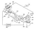
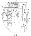
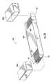
- FIG. 1is a perspective view of an embodiment of the SIS machine of the invention.
- FIG. 2is a perspective back view of the embodiment of the SIS machine of FIG. 1 .
- FIGS. 3 and 4are perspective views of a saw used in the SIS machine of FIG. 1 .
- FIG. 5is a perspective view showing details of the SIS machine of FIG. 1 .
- FIGS. 6 and 7are perspective back views of the embodiment of the SIS machine of FIG. 1 with the outer casing removed.
- FIG. 8is a back view of the embodiment of the SIS machine of FIG. 1 with the outer casing removed.
- FIG. 9is a bottom view of the embodiment of the SIS machine of FIG. 1 with the outer casing removed.
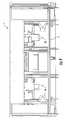
- FIG. 10is a left side view of the embodiment of the SIS machine of FIG. 1 with the outer casing removed.
- FIG. 11is a right side view of the embodiment of the SIS machine of FIG. 1 with the outer casing removed.
- FIG. 12is a perspective view of a saw of the embodiment of the SIS machine of FIG. 1 .
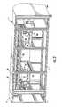
- FIG. 13is a perspective front view of the SIS machine of FIG. 1 with the casing removed.
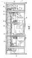
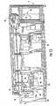
- FIG. 14is a top view of the SIS machine of FIG. 1 with the cutting chamber removed.
- FIGS. 15-17are perspective views of an embodiment of the clamp assembly used in the SIS machine of FIG. 1 .
- FIG. 18is a perspective view showing an alternate embodiment of the clamp assembly used in the SIS machine of FIG. 1 .
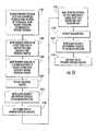
- FIG. 19is a block diagram of the operating system of the SIS machine.
- FIG. 20is a block diagram of another embodiment of the operating system of the SIS machine.
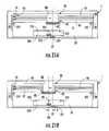
- FIGS. 21A-21Gare views showing the positioning and cutting operations.
- FIGS. 22A-22Dare views showing an alternate embodiment of the positioning and cutting operations.
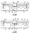
- FIGS. 23A and 23Bare views showing another embodiment of the positioning and cutting operations.
- FIGS. 24A-24Dare block diagrams illustrating an embodiment of the operation of the SIS machine.
- FIG. 25is a block diagram illustrating an embodiment of the operation of the SIS machine.
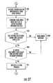
- FIG. 26is a block diagram illustrating an embodiment of the positioning and cutting operation.
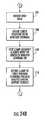
- FIG. 27is a block diagram illustrating an embodiment of the verification process.
- FIGS. 28A and 28Bare block diagrams illustrating an embodiment of the operation of an ordering system.
- FIGS. 29A and 29Bare block diagrams illustrating an embodiment of the operation of an ordering system.
- FIG. 30shows part of the ordering system of FIGS. 12A and 12B .
- FIG. 31is a block diagram illustrating the system for measuring the dimensions of an architectural feature.
- FIG. 32is a block diagram illustrating another embodiment of the operation of an ordering system.
- FIG. 33is a block diagram illustrating yet another embodiment of the operation of an ordering system.
- FIGS. 34 through 42are sample screen shots that may be displayed on the user interface during the cutting operation.
- FIG. 43is a perspective view of an alternate embodiment of the SIS machine.
- FIGS. 44, 45A and 45Bshow one operation of the SIS machine of FIG. 43 .
- FIGS. 46 and 47show another operation of the SIS machine of the invention.
- FIGS. 48A through 48Ishow yet another operation of the SIS machine of the invention.
- FIG. 49is a block diagram illustrating an operation of the SIS machine of the invention.
- FIG. 50is a block diagram illustrating another operation of the SIS machine of the invention.
- FIG. 51is a block diagram illustrating yet another operation of the SIS machine of the invention.
- FIG. 52is a front view of the SIS machine of FIG. 43 .
- FIG. 53is a top view of the SIS machine of FIG. 43 .
- FIG. 54is a perspective view of an embodiment of a dust control system.
- FIG. 55is a top view of the SIS machine of FIG. 43 with the drawer in an open position.
- FIG. 56is a perspective view of the SIS machine of FIG. 43 showing the drawer structure.
- FIG. 57is a perspective view of the drawer of the SIS machine of FIG. 43 .
- FIG. 58is a bottom perspective view of an embodiment of a package packed with a window covering usable in the SIS machine.
- a drive 15such as a rack and pinion is used to automatically slide the door 6 in tracks 12 between open and closed positions.
- Other mechanismssuch as pneumatic or hydraulic cylinders, a rotary motor or the like may be used to open and close the door 6 .
- the door 6may be hinged rather than sliding. The door may also be opened and closed manually.
- Sensors 16such as limit switches, optical sensors, pressure sensitive switches or the like may be provided to detect if the door 6 is closed and to transmit a signal to the operating system indicating the door's status. The operating system may prevent operation of the SIS machine if the door 6 is not closed.
- a platform 20 that supports the window covering during the measuring and cutting operationsis provided in cutting chamber 8 adjacent to opening 5 such that a user can place a window covering on the platform 20 when the door 6 is open.
- the platform 20comprises a substantially horizontal surface that is dimensioned to be able to receive and support a range of blind sizes.
- a separate access opening 22is provided on one side wall 24 of housing 4 such that a blind may be loaded through access opening 22 into cutting chamber 8 from the end of the machine rather than through door 6 .
- Opening 22is useful for window coverings that are longer than the length of the SIS machine.
- opening 22may be used to load the vanes of a vertical blind into the machine because such vanes may be manufactured in relatively long lengths that cannot be accommodated through opening 5 .
- One end of the vanescan be inserted through the access opening 22 with the other end of the vanes extending from the housing 4 through opening 22 .
- a feed tube or other conveyormay be provided that communicates with opening 22 and allows the window covering to be inserted into the machine remotely. The ends of the vanes located in the cutting chamber 8 can then be cut to length as will hereinafter be described.
- a lateral support surface 28located along the front edge of the cutting chamber 8 adjacent to the front edge of platform 20 is a lateral support surface 28 that in the illustrated embodiment is defined by a plurality of rollers 26 .
- the lateral support surface 28facilitates the movement of the window covering across the platform 20 during the measuring and cutting operations. During the measuring and cutting operations, the window covering is pressed against the lateral support surface 28 and slid across the platform 20 as will hereinafter be described.
- the use of the rollers 26facilitates the sliding movement of the window covering on platform 20 .
- the rollers 26may be eliminated and replaced by a stationary vertical wall where the window covering is pressed against and slides along the stationary wall.
- the wallmay comprise a low friction surface. Further, another low friction device may be used in place of the rollers or wall if desired.
- a movable belt, a plurality of bearings or other low friction surface or devicemay comprise the lateral support surface 28 .
- FIGS. 43, 52, 53 and 55 through 57An alternate embodiment of the SIS machine is shown in FIGS. 43, 52, 53 and 55 through 57 where like reference numerals are used to identify like components described with reference to the embodiment of FIG. 1 .
- the SIS machinecomprises an internal frame that supports the cutting, measuring and operating systems of the SIS machine.
- An outer housing 4is provided to cover the internal mechanisms of the SIS machine.
- An opening 4405is provided in the front of the housing 4 to allow access to the interior cutting chamber 8 of the apparatus.
- Cutting chamber 8may be covered by a transparent window 4309 to allow a user to observe the cutting and measuring operations.
- a drawer 4302is movably mounted in the opening 4305 such that it can be moved horizontally between an open position ( FIGS. 55 and 56 ) and a closed position ( FIGS. 43, 52 and 53 ).
- the drawer 4302comprises a platform 20 for supporting the window covering during the positioning and cutting operation and a front wall 4306 that closes the opening 4305 when the drawer 4302 is in the closed position to isolate the cutting chamber 8 from the external environment.
- the front wall 4306also supports the lateral support surface 4328 .
- the lateral support surface 4328may comprise the plurality of rollers 4326 or other low friction devices for facilitating the movement of the window covering across the platform 20 during the measuring and cutting operations.
- the cutting chamber 8 in the embodiment of FIG. 43is configured substantially the same as the cutting chamber 8 in the embodiment of FIG. 1 .
- One side wall of the housing 4includes a cut-out area or opening 4322 at one end of the opening 4305 adjacent the platform 20 to accommodate window coverings which are longer than the machine.
- vertical window coveringsmay be manufactured in lengths that are longer than the length of opening 4305 or machine 1 .
- the cut-out area or opening 4322is open towards the front of the SIS machine and is positioned such that a window covering supported on platform 20 may extend out of opening 4322 .
- the window coveringis placed on the platform 20 by inserting the window covering through opening 4323 ( FIG. 57 ) such that it extends off of the end of the platform 20 to the side having opening 4322 .
- Opening 4322may be covered by a movable door 4323 that is opened to allow access to opening 4322 .
- saws 30 and 32located at either end of platform 20 are cutting devices such as saws 30 and 32 for cutting the window covering to the desired size.
- the saws 30 and 32are substantially identical such that specific reference will be made to saw 30 .
- Saw 30comprises a saw motor 34 for rotating the arbor 38 on which the saw blade 36 is mounted.
- the motor 34is connected to the saw arbor 38 via a transmission.
- the motor 34 , transmission and arbor 38are mounted on a platform 40 that is in turn supported on rails 42 .
- the rails 42support platform 40 such that platform 40 can reciprocate transversely to the platform 20 to bring the saw blade 36 into contact with a window covering supported on and extending over the end of platform 20 .
- Platform 40moves saw blade 36 through the window covering to cut the window covering.
- the sawsmay be replaced by other cutting devices.
- die cutters or lasersmay be used to make the cut.
- a combination of cutting devicesmay be used depending on the window covering material, material thickness or the like.
- Drive 43may comprise a motor 44 that is supported on the platform 40 and that rotates a pinion 46 that engages a rack 48 mounted on frame 2 .
- the motor 44When the motor 44 is actuated, the pinion 46 is rotated and through its engagement with the rack 48 reciprocates platform 40 on rails 42 toward and away from the window covering.
- two saw blades 36 and 36 aare provided with each of saws 30 and 32 to minimize routine maintenance of the machine.
- a saw bladehas a limited life span such that after a predetermined amount of use the blade must be replaced. If only one saw blade is provided on each saw, more maintenance of the SIS machine is required. To minimize the routine maintenance of the SIS machine, two blades may be provided on each saw where the blades may be changed automatically.
- each sawcomprises a motor 34 for driving arbors 38 and 38 a that support blades 36 and 36 a , respectively.
- the arbors 38 and 38 aare mounted on a housing 50 such that blades 36 and 36 a are supported in an overlapping relationship.
- Housing 50can pivot on an axle 51 relative to the platform 40 about an axis parallel to the arbors 38 and 38 a .
- the housing 50is shown in a first orientation where blade 36 is positioned to cut a window covering and blade 36 a is positioned as a replacement blade.
- the housing 50is maintained in the illustrated position by a locking mechanism 56 that locks the housing 50 relative to the platform 40 .
- the locking mechanism 56comprises a retractable post where the post is extended from the platform 40 to engage a mating receptacle on the housing 50 to lock the housing 50 relative to the platform 40 .
- the post 56is retracted from the receptacle allowing the housing 50 to rotate on axle 51 .
- a pair of stops 62 and 64comprising bumpers 52 and 54 and sensors 58 and 60 ensure that the housing 50 assumes the correct orientation as will hereinafter be described.
- Sensors 58 and 60may comprise limit switches, optical sensors, pressure sensitive switches or any other sensor capable of sensing the orientation of housing 50 and generating a signal indicative of the orientation.
- the stops 62 and 64are movably mounted such that each stop can be extended from or retracted into the platform 40 .
- Blade 36cuts the window coverings as will hereinafter be described. Each cut is counted and the total number of cuts is stored in the memory of the operating system. When the total number of cuts equals a predetermined maximum number of cuts, blade 36 is replaced. The predetermined maximum number of cuts will depend on the blade construction and the material being cut, however, the predetermined maximum number of cuts is preferably selected such that the blade is replaced before wear on the blade degrades its cutting performance. When the total number of actual cuts equals the predetermined number of cuts, the locking mechanism 56 is withdrawn from the housing 50 thereby allowing the housing to freely rotate relative to platform 40 .
- the first stop 62is retracted into housing 50 and the second stop 64 is extended from housing 50 .
- the saw blades 36 and 36 aspinning on arbors 38 and 38 a , create enough inertia that the housing 50 rotates on the support axle 51 when the locking mechanism 56 is retracted without the use of any other drive mechanism.
- the housing 50rotates until a flange 66 on the housing contacts stop 64 . In this position, the saw blade housing 50 has rotated 180 degrees and is oriented such that the second blade 36 a is positioned to cut the window covering and the first saw blade 36 is in the reserve position.
- Sensor 60associated with stop 64 , produces a signal indicating that housing 50 has rotated to the new position.
- the signal from sensor 60is transmitted to the CPU and the locking mechanism 56 is actuated to lock housing 50 in the new position.
- the total number of cutsare counted and maintained in memory for the new blade 36 a . Both blades 36 and 36 a may be replaced during a single service visit when the second blade reaches a predetermined maximum number of cuts.
- the operating system that controls the measuring and cutting operationsmust be informed as to which blade is in the cutting position.
- the sensors 58 and 60 associated with the stops 62 and 64provide this information to the operating system by transmitting a signal to the CPU when the housing 50 contacts the stop.
- the operating systemthen adjusts the measuring and cutting operations to account for the difference in saw blade positions.
- the saw blades 36 and 36 aare positioned such that the blades are in the same cutting plane.
- the operating systemdoes not adjust the cutting operation based on which blade is being used.
- such an arrangementrequires additional space because the coplanar blades require more room than the overlapping blades shown in the drawings.
- the sensors 58 and 60 associated with the stops 62 and 64may be used to provide feed back to the CPU that the blades are properly positioned.
- a clamp assembly 80comprises a clamping jaw 82 that can be extended and retracted to trap a window covering against the lateral supporting surface 28 , 4328 .
- Jaw 82is supported for reciprocating linear movement on a bar or bearing 83 that rides on rails or bearings 86 where jaw 82 is moved over the rails 86 by a drive 87 such as a pneumatic cylinder, electric motor, solenoid, hydraulic cylinder or the like.
- the drive 87may also comprise a rack and pinion or ball screw drive or the like.
- the jaw 82may be extended to clamp a window covering against the lateral supporting surface 28 , 4328 and retracted to release the window covering.
- FIG. 57shows the clamp assembly 80 for the embodiment of the SIS machine shown in FIG. 43 .
- the clamp assembly in this embodimentis substantially the same as in the embodiment of FIGS. 5, 12 and 15-18 except that the clamp assembly 80 is mounted on the drawer 4302 such that the clamp assembly moves with the drawer.
- the clamp assembly 80is mounted on a carriage 88 that is mounted on a linear drive such as a ball screw drive or rack and pinion. Rotation of pinion (not shown) engages rack 93 to reciprocate the carriage 88 along the length of platform 20 .
- the pinion or other drive mechanismis rotated by a stepper motor or servomotor 91 such that the position of the carriage 88 and clamp assembly 80 along the platform 20 can be controlled with great accuracy.
- Each rotation of the stepper motor or servomotor 91translates into a predetermined length of linear travel of the clamp assembly 80 along the platform 20 .
- the rotation of the stepper motor or servomotor 91can be precisely controlled to precisely control the linear motion of the clamp assembly 80 and its position along platform 20 .
- the carriage 88supports sensor 92 such as an optical sensor.
- sensor 92is used to measure and position the window covering relative to the saws 36 and 36 a as will hereinafter be described.
- FIG. 18An alternate embodiment of the clamp assembly is shown in FIG. 18 at 280 that is similar to clamping jaw 80 as previously described.
- Clamp assembly 280is provided that comprises a clamping jaw 282 that can be extended and retracted to trap a window covering against the lateral supporting surface 28 .
- Jaw 282is supported for reciprocating linear movement as previously described.
- the jaw 282may be extended to clamp a window covering against the lateral supporting surface 28 and retracted to release the window covering as previously described.
- the clamp assembly 280is mounted on a carriage 88 that is mounted on a linear drive as previously described to reciprocate the carriage 88 along the length of platform 20 .
- clamping jaw 282In order to position the window covering relative to the clamping jaw 282 , clamping jaw 282 is provided with a physical engagement member such as pin 285 .
- the position of the pin 285 relative to the clamping jaw 282is known.
- pin 285may be located in the center of clamping jaw 282 .
- the window covering and packageare provided with a hole 201 located on the window covering 200 ( FIGS. 23A and 23 B).
- the window covering 200is inserted into the SIS machine and placed on platform 20 such that the pin 285 is inserted into the hole 201 in the window covering.
- the position of the window covering 200 relative to the clamping jaw 282is known.
- the hole in the window coveringis located at the center of the window covering such that the pin locates the center of the window covering such that the center of the window covering is known to the SIS machine.
- the pin 285is located on the center of the clamping jaw 282
- the clamping jaw 282is also aligned with the center of the window covering.
- a locating pinis located on the machine housing rather than on the clamping jaw 282 .
- the first engagement elementcomprises a pin 4402 mounted on the lateral support surface 4328 of the drawer 4302 .
- the pin 4402projects from the lateral support surface 4328 at the center of the platform.
- the pin 4402is movable between an extended position where it extends beyond the lateral support surface 4328 (e.g. beyond rollers 4326 ) and can engage a window covering and a retracted position where it is positioned behind the lateral support surface 4328 (e.g. behind rollers 4326 ).
- the pin 4402may be moved by a solenoid or other similar drive 4404 .
- the drive 4404is controlled by the PC to selectively and automatically extend and retract the pin 4402 .
- the pin 4402engages a mating engagement element in the form of alignment hole 201 formed on the package and/or window covering 200 that closely receives pin 4402 .
- the alignment hole 201is located at the center of the package and window covering and locates the window covering in a known position on the platform 20 .
- the drive 4404is activated to extend pin 4402 beyond lateral support surface 4328 (Block 4901 ).
- the useropens drawer 4302 (Block 4902 ) and places the window covering on the platform 20 such that the center pin 4402 extends into the centrally located hole 201 on the package/window covering (Block 4903 ).
- the drawer 4302is closed by the user (Block 4904 ).
- the clamp assembly 80 and clamping jaw 82are positioned at the center position of the platform 20 and the window covering is centered relative to the clamping jaw 82 by the pin 4402 .
- the clamping jaw 82is extended to force the window covering against the lateral support surface 4328 (Block 4905 ).
- the pin 4402is then retracted from the window covering by drive 4404 (Block 4906 ).
- the various sensors described hereintransmit signals to the CPU of the system operating system to control operation of the SIS machine. Further, the various drives described herein are controlled by the CPU to position and cut the window covering.
- the CPUmay be located in the machine 1 or it may be located remotely from the machine.
- one embodiment of the operating system of the SIS machine 1includes a computing platform 100 .
- the platformis controlled by a processor 102 which serves as the central processing unit (CPU) for the platform.
- Memory 104is typically divided into multiple types of memory or memory areas such as read-only memory (ROM), and random access memory (RAM).
- a plurality of general-purpose adapters, 106are present. At least one, in this example, serves to connect the computing platform to a network 108 .
- the networkmight be a corporate intranet, a local area network (LAN), the public switched telephone network, a wireless network, the internet or a combination of such networks.
- Computer program code instructions for implementing the appropriate applications and controlling the SIS machineare stored on the fixed medium 110 .
- a user interface 112such as a touch screen and/or audio speakers is provided to receive input from the user and to display output to the user.
- Other user interface devicesmay be used such as voice recognition, wireless communication technology, joy sticks, video displays, monitors, keyboards, thumbwheels or the like.
- User interface 112is intended to include any apparatus that allows the user to input data to the system and/or that allows the system to display information to the user.
- a common databasecan be implemented in whole or in part on a single computing platform like that shown in FIG. 19 .
- a common databasemay be stored on a database server such as an SQL server.
- Processor 120 , adapters 122 , and memory 124function similarly to those of computing platform 100 . If a corporate intranet is used for connectivity, the applications or modules on computing platform 100 can be accessed from a client workstation via a web page.
- a computer program which implements parts of the invention through the use of a system like that illustrated in FIG. 19can take the form of a computer program residing on a computer usable or computer readable tangible storage medium such as a diskette.
- a computer program product containing the program of instructionscan be supplied in such a form, and loaded on the machines involved, either directly, or over a network.
- the mediummay also be a stream of information being retrieved when the computer program product is “downloaded” through the Internet.
- the computer programscan reside on any medium that can contain, store, communicate, propagate, or transport the program for use by or in connection with an instruction execution system, apparatus, or device.
- the computer-usable or computer-readable mediummay be, for example but not limited to, an electronic, magnetic, optical, electromagnetic, infrared, or semiconductor system, apparatus, device, or propagation medium.
- a tangible computer-readable mediumwould include a portable computer diskette or portable fixed disk, an optical fiber, a compact disc read-only memory (CD-ROM), and a digital versatile disc read-only memory (DVD-ROM).
- a processor 202 in the form of a PC and a separate PLC controller 203 associated with the drive 91 of clamp assembly 89are used to control operation of the SIS machine to position and cut the window covering.
- the system of FIG. 20is otherwise the same as the system of FIG. 19 .
- the center position CP of the clamp assembly 80 relative to the cutting devices such as saws 30 and 32may be determined.
- the center position CPis the point mid-way between the active blades of the two saws 30 and 32 and is shown, for example, in FIG. 21 .
- the clamp assembly 80is moved along the platform 20 in a first direction until the clamp reaches the end of travel.
- the end of travelmay be identified by a sensor 105 such as limit switch, optical sensor or the like.
- the sensor 92 mounted on the clamp assembly 80may also be used for this function.
- a signal from the appropriate sensoris provided to the CPU 102 indicating that the clamp has reached the end of travel.
- the CPUthen sends a signal to drive 89 such that the stepper motor or servomotor 91 rotates a predetermined number of rotations until the clamp assembly 80 is located in the center position CP of the platform 20 .
- the machineis then ready to cut a window covering.
- Locating the center positioncould also be performed other than at start up of the machine and may be performed by other processes. For example a separate centering switch may be provided that is located at the center position and that is “contacted” by the clamp assembly 80 either physically, magnetically, optically or electronically to identify the center position. Further, while in one embodiment the clamp assembly 80 operates from the center position CP of the platform 20 , it is to be understood that the clamp assembly 80 could initiate the cutting operation from any start position provided that the start position is a known position relative to the blades of saws 30 and 32 .
- the userplaces a window covering 200 in the cutting chamber 8 on platform 20 (Block 701 , FIG. 24A ).
- the usermay be directed where to place the window covering by visual, audio or other commands from processor 102 via user interface 112 .
- the platform 20may also have a visual indicator directing the user as to the proper placement of the window covering on the platform.
- the platform 20may include indicia such as printing indicating the proper placement of the window covering.
- proper placement of the window covering on platform 20results in the window covering being detected by sensor 92 ( FIG. 21A ). Once the window covering is properly positioned on the platform 20 a signal from sensor 92 may be transmitted to and received by the CPU indicating the presence of a window covering (Block 702 ).
- the CPU 102actuates drive 15 to automatically close and lock door 6 or drawer 4302 .
- the door 6 and drawer 4302may be closed manually.
- the door 6 and drawer 4302isolate the cutting chamber 8 from the external environment and user (Block 703 ).
- Sensor 16transmits a signal to the CPU indicating that the door 6 is in the closed position (Block 704 ).
- the window covering 200may be cut in the package or it may be removed from the package before being inserted into the machine.
- a suitable packageis disclosed in U.S. patent application Ser. No. 10/908,728 filed May 24, 2005 and is incorporated in its entirety herein.
- the operating systemcan be programmed to cut only window coverings in the package or only window coverings out of the package.
- the machinecan be programmed to cut the product in either form, provided that the form of the product is input to the CPU prior to the cutting operation.
- “Window covering” as used herein for explaining the operation of the SIS machineincludes both the window covering in the package and the window covering without the package and is represented by element 200 in the Figures.
- the package or the window coveringmay be provided with a mark 101 at its longitudinal center where mark 101 can be sensed by sensor 92 .
- the mark 101may include reflective tape, reflective ink or other optically identifiable surface if sensor 92 is an optical sensor, a physical characteristic such as an indentation if the sensor is a mechanical sensor, a magnetic stripe if the sensor is a magnetic sensor or other combination of mark and sensor provided that sensor 92 can determine the center of the blind by reference to the mark.
- mark 101may be eliminated and the physical engagement of the window covering/package with pin 285 is used to locate the center of the window covering.
- window covering/package 200is placed on platform 20 and the pin 285 is manually inserted into the centering hole 201 formed in the center of the window covering 200 when the user loads the window blind into the SIS machine, FIG. 25 .
- FIGS. 23A and 23 Bwindow covering/package 200 is placed on platform 20 and the pin 285 is manually inserted into the centering hole 201 formed in the center of the window covering 200 when the user loads the window blind into the SIS machine, FIG. 25 .
- the window covering/package 200is placed on platform 20 in drawer 4302 and the pin 4402 is manually inserted into the centering hole 201 formed in the center of the window covering 200 when the user loads the window blind into the SIS machine, FIG. 49 .
- the engagement of the pin 285 , 4402 with the centering hole 201 on the window coveringlocates the center of the window covering relative to the SIS machine. In such embodiments the use of sensors to determine the center of the window covering can be eliminated. Further, if the retractable pin on the lateral surface is used, the pin is retracted after the clamping jaw 82 clamps the window covering against lateral support surface 4328 .
- the packageis formed with a hole that is coextensive with the centering hole on the window covering such that the pin can pass through the hole in the package and engage the window covering.
- a hole on the packagecan be used if the window covering is aligned within the package.
- the centering hole on the window coveringmay be made directly in the window covering, such as in the head rail, or a centering bracket with a hole formed therein may be attached to the window covering.
- the centering bracket with the centering holemay be fixed to the center of the head rail.
- the physical engaging membersmay include any physical structures capable of engaging one another to locate the window covering relative to the clamp.
- the male membermay extend from the window covering or package and engage a female receptacle on the clamping jaw. These members may have any shape and a plurality of mating pairs of engaging members may be used.
- a transaction record 230is created by CPU 102 and stored in memory 104 (Block 705 ).
- the transaction record 230may be populated with applicable information related to the transaction such as time, date and location of the SIS machine, customer information such as name, address, payment information, bar code number, product cut width, time spent during cutting, number of times the user navigates to each screen page and any errors reported by the PLC or the like (Block 706 ). Other information may also be stored in the transaction record.
- User input datais also transmitted to and received by CPU 102 identifying, at least, the finished or cut size of the window covering (Block 707 ).
- the process for entering this informationwill be discussed in detail hereinafter.
- the usermay be required to input other information regarding the window covering such as the type of blind, color, style, stock size or the like.
- the usermay also be requested to input other information such as name, address, payment information or the like. Any or all of this information may be stored in transaction record 230 .
- the clamp assembly 80is moved along the platform 20 by drive 89 from the known center position CP until the sensor 92 locates the center mark 101 of the window covering/package 200 (block 708 ).
- the clamp assemblyis stopped in a position where the center of the clamp assembly 80 is aligned with the center CW of the window covering/package (Block 709 ), FIG. 21B .
- the position of clamp assembly 80 when positioned at the center CW of the window covering/package 200is known.
- the CPUdetermines the distance D between the center CW of the window covering/package 200 and the center position CP to establish the location of the window covering/package 200 relative to the machine.
- FIGS. 21C, 45Bthe clamp assembly 80 is aligned with the center CW of the window covering/package 200 .
- the drive 87extends jaw 82 to force the window covering/package 200 against the lateral support surface 28 (Block 710 , Block 4402 , 4905 ), FIGS. 21C, 45B .
- the clamp assembly 80is centered on the window covering/package 200 ; the position CW of the clamp assembly 80 relative to the center position CP is known; and the window covering/package 200 is trapped between the jaw 82 and the lateral support surface 28 .
- the clamp assembly 80is also positioned at the center of platform 20 .
- the CPUdetermines how far to move the window covering/package to properly position it in front of the saws 30 and 32 (Block 711 ).
- the userenters into the processor 202 and the processor receives whether the window covering is intended to be mounted as an inside mount or an outside mount (Block 4404 ) and the desired size of the window covering (Block 4403 ). If an inside mount is selected, the processor 202 automatically deducts a predetermined length from the desired size entered by the user to obtain the final dimension of the window covering (Block 4405 ). If an outside mount is selected, the final dimension of the window covering is the desired size input by the user. The user may also enter the window height. The information entered by the user is stored in the record for that transaction.
- the CPU 102accesses the desired cut size of the window covering as entered by the user. From this dimension the CPU calculates how far the center of the window covering must be positioned from the saws 30 and 32 to achieve the desired cut size of blind (Block 4406 ). The CPU divides the desired finished size by two to obtain a resulting distance from the center of the window covering to each end hereof. The center of the window covering must be positioned this resulting distance from the saw. The user also enters whether the window covering is for an inside mount or an outside mount. For an inside mount a small distance is subtracted from the desired size to accommodate for the space needed to mount inside of a window frame.
- the CPUdetermines that the distance from the center of the window covering to each of the saws must be 171 ⁇ 2 inches. For an inside mount 1 ⁇ 2 of an inch may be deducted from the desired size before dividing the desired size by 2. The CPU can make this determination without any information regarding the stock size of the blind or the amount of material to be cut from the end of the blind. For some applications material may be cut from only one end such as vanes for vertical blinds.
- the PLC 203determines how far to move the window covering/package to properly position it in front of the saws.
- the processor 202transmits to the PLC 203 the final dimension of the window covering as entered by the user and as corrected to account for an inside mount, if necessary (Block 4407 ).
- the PLC 203determines how far the center of the package must be positioned from each saw to obtain the desired size of the window covering as previously described (Block 4408 ).
- the PLC 203divides the final dimension provided by the processor 202 by two to obtain a half length.
- the half lengthis equal to the distance from the center of the package/window covering to the end of the window covering and corresponds to the distance the center of the blind must be positioned from each saw.
- the PLC 203makes this determination without any information regarding the stock or starting size of the window covering, the amount of material that will eventually be cut from the end of the window covering or whether the window covering is intended for an inside mount or an outside mount. The window covering is then cut as described below.
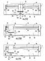
- the clamp assembly 80is then moved toward one end of the machine based on this determination such that the center of the blind is positioned the resulting distance from the saw (Block 712 , FIG. 24C ) and FIG. 21D .
- Clamp assembly 80moves the window covering/package such that the position of the clamp assembly relative to the window covering/package 200 remains fixed.
- the clamp assembly 80is moved such that the window covering/package is positioned in front of one of saws 30 or 32 with the center of the window covering spaced from the saw the predetermined distance.
- FIG. 17also shows the clamp assembly 80 moved to an end of platform 20 . Secondary clamps 99 may also be used adjacent each of the saws to hold the window covering in position during the cutting operation ( FIGS. 5, 15 ).
- the secondary clamps 99are extended to trap the window covering against the lateral surface 28 .
- the saw bladeis rotated at high speed and the saw is moved toward the window covering/package by drive 43 such that the saw engages and cuts the window covering at the desired location (Block 713 , FIG. 24C ) and FIG. 21E .
- the clamp assembly 80is then moved toward the opposite end of the machine moving the window covering/package 200 with the clamp assembly (Block 714 ).
- the position of the clamp assembly 80 relative to the window covering/package 200remains fixed.
- the clamp assembly 80is moved such that the window covering/package is positioned in front of the other of saws 30 and 32 , FIG. 21F with the center of the window covering spaced from the saw the predetermined distance.
- Secondary clamps 99may also be used adjacent each of the saws to hold the window covering in position during the cutting operation ( FIGS. 5, 15 ).
- the secondary clamps 99are extended to trap the window covering against the lateral surface 28 .
- the saw bladeis rotated at high speed and the saw is moved toward the window covering/package by drive 43 such that the saw engages and cuts the window covering at the desired location (Block 715 , FIG. 24C ) and FIG. 21F .
- the jaw 82holds the window covering/package 200 tight against the lateral support surface 28 to support the window covering/package while it is cut. Both ends of the blind may be cut simultaneously by moving one or both of the saws relative to the window covering rather than moving the window covering.
- the SIS machineuses controllable motors for the saws and may cut window coverings either in or out of the packaging
- the SIS machinemay cut a wide variety of window coverings including wood, plastic, fabric, vinyl and aluminum and a variety of styles including horizontal blinds, vertical blinds, woven shades, pleated shades, Roman shades and cellular blinds.
- the sawscan also cut the shade panel and the head rail and bottom rail in one cut.
- the rotational speed of the saws and the feed rate of the sawscan be controlled on a per cut basis based on the type of blind loaded in the SIS machine such that the saws may cut a wide variety of materials.
- the engagement elementprojects from the lateral support surface 4328 .
- the engagement elementcomprises a retractable pin 4520 that is offset from the center of the platform ( FIGS. 55-57 ).
- the pin 4520engages an engagement element comprising an alignment hole 4522 formed on the package 200 for a vertical window covering. Alignment hole is offset from the center of the package 200 and the center of the window covering and locates the vertical window covering in a known position on the platform 20 .
- the pin 4520is movable between an extended position where it extends beyond the lateral support surface and can engage a window covering and a retracted position where it is positioned behind the lateral support surface.
- the pin 4520may be moved by a solenoid or other similar drive 4521 .
- the drive 4521is controlled by the PC to selectively and automatically extend and retract the pin.
- the drawer 4302is opened and the user places the package containing the vanes or head rail 200 on the platform such that the pin 4520 extends into the alignment hole 4522 on the package/window covering package.
- the drawer 4302is then closed. Because vertical window coverings may be longer than the SIS machine, opening 4322 ( FIGS. 43 and 56 ) is provided at one end of the SIS machine that allows the package containing the vanes or head rail 200 to extend out of that end of the cutting machine, if necessary, as shown in FIGS. 46 and 47 .
- the clamp assembly 80is positioned on the platform 20 centered on the location of the alignment hole 4522 and the pin 4520 .
- the clamping jawis extended to press the package 200 against the lateral support surface 4328 ( FIG. 47 ) and the pin 4520 is withdrawn from the package.
- a vertical window covering materialis cut from only one end of the vanes and from one end of the head rail.
- the head rail and vanesare stored in separate packages and are cut separately.
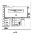
- the userselects an icon on the touch screen to initiate the cutting process (Block 5001 ).
- a sales associateenters a security code and enters that a vertical blind is to be cut.
- the useralso enters whether the head rail or vanes are to be cut (Block 5002 ).
- the clamp assemblyis shuttled back and forth along the length of the platform such that the optical scanner 92 scans the package to read the bar code 220 on the package (Block 5003 ).
- a separate flip card 221 having a bar codeis held in front of scanner 92 such that it is scanned by the optical scanner 92 (Block 5004 ).
- the userselects the flip card that corresponds to the selected vanes and holds the flip card where it can be read by the optical scanner. While the flip card is described as being used with the vanes and the head rail is described as having a bar code on the package, the bar code on the package and the flip card may be used with any type of window covering.
- the code from the bar codeis used by the PC to obtain from the look-up table the detailed information for the window covering.
- the clamp assembly 80is moved to the position on the platform centered on the location where the offset pin engages the alignment hole in the package. As previously explained, while this position does not correspond to the center of the platform or the center of the package, this position is known.
- a transaction recordis created for the window covering and stored in memory as previously described with respect to horizontal window coverings.
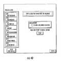
- the monitorFor a head rail the monitor displays a prompt for whether the window covering is an inside mount or an outside mount. The user then enters into the user interface and the PC receives a signal indicating whether the window covering is intended to be mounted as an inside mount or an outside mount (Block 5006 ). For vanes the monitor displays a prompt for whether the window covering is an inside mount, an outside mount or exact. For vanes the user is also provided with an additional option of “Exact” where the final dimension of the vanes is the same as the desired size entered by the user. The user then enters into the user interface and the PC receives a signal indicating whether the window covering is intended to be mounted as an inside mount, an outside mount or exact (Block 5009 ).
- the monitordisplays a prompt asking for the desired length of the head rail or vanes, as appropriate.
- the userthen enters into the user interface and the PC receives the desired length of the head rail or vanes (Block 5005 ).
- the PCautomatically deducts a predetermined length from the desired size of the head rail entered by the user to obtain the final dimension of the head rail (Block 5007 ).
- the final dimension of the head railis the desired size input by the user (Block 5008 ).
- the PCdeducts a predetermined length from the desired size of the vanes to account for the height of the head rail.
- the final dimension of the head railis the desired size input by the user minus the head rail dimension (Block 5010 ). If an inside mount is selected, the PC automatically deducts the predetermined head rail dimension and a second predetermined length from the desired size of the vanes entered by the user to obtain the final dimension of the vanes (Block 5011 ). If “Exact” is selected the final dimension of the vanes equals the desired size entered by the user” (Block 5012 ).
- the PLCdetermines how far to move the package to properly position the head rail or vanes in front of the saw.
- the head rail or vanesare retained in the package such that the package and head rail or vanes are cut simultaneously.
- the packagesretain the head rail and vanes such that a first end of the head rail or vanes is located a known distance C from a first end of the package.
- the cutis made at the opposite end of the package.
- the alignment hole in the packageis spaced a known distance Z from the first end of the package. For a particular window covering the values for C and Z are obtained from the look-up table that was accessed using the bar code (Block 5013 ).
- YFinal Dimension ⁇ Z+C, where Y is the distance between the alignment hole and the saw (Block 5014 ).
- the final dimension of the vertical window coveringis Y+Z ⁇ C.
- the PCtransmits to the PLC the final dimension of the window covering as entered by the user and including the deductions calculated by the PC, if any. Using this dimension, the PLC determines how far the alignment hole must be positioned from the saw to obtain the final dimension of the window covering as calculated in accordance with the equation set forth above (Block 5014 ). This location is converted to an encoder count that corresponds to the calculated value Y. The PLC makes this determination without using any information regarding the stock or starting size of the blind or the amount of material that will eventually be cut from the end of the blind.
- the PLCcontrols the drive for the clamp assembly to move the clamp assembly toward one saw to position the alignment hole the calculated distance Y from that saw (Block 5015 ). Because a limited amount of space is provided between the saw 32 and the end of the cabinet of the SIS machine the window covering cannot be advanced more than distance S beyond the saw. Because it may be necessary for the clamp assembly to move the window covering more than distance S to reach the calculated Y position, the SIS machine uses an iterative process to cut vertical window coverings.
- the window coveringis indexed toward the saw by the clamp assembly.
- An optical sensor 105is positioned in front of the saw blade 32 that senses the first end of the package as it is indexed toward the saw. The first end of the package is then moved past the saw. If the clamp assembly reaches the calculated Y value (encoder count) before moving distance S, the clamp assembly is stopped at the encoder count and the stationary clamp 99 associated with this saw is extended to hold the package (Block 5016 ). The saw is moved toward the package containing the head rail or vanes such that the saw engages and cuts the first end of the package and the head rail or vanes to the final dimension (Block 5017 ).
- the stationary clamp 99 associated with this sawis extended to hold the package and window covering (Block 5018 ).
- the sawis moved toward the package containing the window covering such that the saw engages and cuts a length equal to S from the first end of the package (Block 5019 ). This process is repeated until the clamp assembly reaches the calculated Y value and the package and vanes or head rail are cut to the final dimension (Block 5016 ).
- the stationary clamp 99is retracted and the clamp assembly 80 moves the window covering and package to the start position.
- the clamping jaw 82is retracted to release the window covering and package.
- the drawer 4302is opened to allow the user to remove the window covering 200 from the platform.
- FIGS. 48A through 48I, 51 and 58the process for squaring a window covering and for cutting a window covering with a valance will now be described.
- a window coveringPrior to cutting a window covering it is necessary to ensure that all of the components (head rail, bottom rail, slats, shade panel, woven element, cells, etc.) are squared so that the cut elements all have the same cut width.
- a valanceis dimensioned such that it is longer than the window covering with which it is associated in order to completely cover the head rail when the window covering is installed.
- a specially configured package and cutting processis used for the automatic squaring of the window covering components and for window coverings with valances a specially configured package and cutting process is used. The process provides automatic squaring of the window covering components and allows the window covering and valance to be automatically cut using the SIS machine while maintaining the length differential between the valance and the window covering.
- FIG. 48Aa window covering and package 200 is shown where the package comprises a box that is configured such that the valance extends from the box and is movable along its longitudinal axis relative thereto.
- a suitable package 200is shown in FIG. 58 .
- Package 200is provided consisting of an open-ended box or sleeve 5822 that is a rectangular container that is open at both ends.
- the window coveringis oriented in box 5822 such that it is centered in the box with the head rail, slats, bottom rail and valance 201 extending along the long axis of the box 5822 .
- the window covering 203is supported in box 5822 such that it extends beyond the ends of box 5822 with the ends of valance 205 extending beyond the ends of window covering 203 .
- end caps 5840cover the open ends of the box 5822 .
- the end caps 5840may be secured to the box 5822 by any releasable connection including a shrink wrap, adhesive, tear-away tabs or the like.
- the end caps 5840are removed from box 5822 prior to cutting and may be replaced on the box 5822 after the cutting operation to retain the cut window covering in box 5822 .
- the box 5822is useful for a package for window coverings with valances, the box may be used with any window covering to provide the automatic squaring of the components of the window covering as will be described.
- the window coveringis packaged such that the window covering components and valance 205 extend beyond the end of the package 200 and can be moved along the longitudinal axis relative to the package and one another as represented by arrow A in FIG. 48A (Block 5101 ).
- the valance 205extends beyond the ends of the window covering 203 a distance equal to the final desired length differential between the valance and the window covering.
- the length of valance extending beyond the end of the window covering 203is 1 ⁇ 4 inch.
- valance extending beyond the end of the window coveringis exaggerated for illustrative purposes.
- One end of the valancemay extend beyond the end of the package the entire length differential or both ends of the valance may each extend beyond the end of the package a portion of the total length differential as shown in FIG. 48A .
- the position of the clamp assembly relative to the sawsis calculated based on a distance from a known location (e.g. center of the window covering) and the clamp assembly is positioned based on the calculated distance from the known location to the saw.
- the window covering and package 200are moved in a first direction, as represented by arrow B in FIG. 48B , until the end of the window covering strikes a squaring surface that is selectively moved into the path of travel of the window covering (Block 5102 ).
- the squaring surfaceis arranged such that it is perpendicular to the direction of travel of the window covering.
- the window covering 203is moved against the squaring surface until the end of all of the window covering components abut the squaring surface and are in a common plane or “square”.
- the squaring surfaceis the face of the saw blade 36 R.
- the saw blade 36 Ris moved to the extended position where it intersects the path of travel of the window covering; however, the saw blade 36 R is not rotated. While the saw blades 36 L and 36 R are used as the squaring surfaces in the illustrated embodiment, the squaring surface may be a separate component that is moved into in the path of travel of the blade.
- the window coveringis moved one half the stock length of the window covering from the saw blade.
- the opposite saw 36 Lis extended and the package 200 , window covering 203 and valance 205 are moved toward the opposite saw, arrow C, until the valance 205 and the end of the window covering 203 strike the opposite saw blade 36 L (Block 5103 ).
- the window covering 200 and valance 201are moved against the saw blade 36 L until the window covering and valance abut the saw blade and the second ends of the valance and the components of the window covering are coplanar and square.
- the saw bladeis retracted (Block 5104 ) and the clamp assembly 80 is moved to the calculated position, arrow D, to position the window covering in front of the saw 35 L (Block 5105 ).
- the stationary clamp 199is extended to hold the window covering 203 in position and the saw 36 L is rotated at high speed and moved into engagement with the window covering 203 and valance 205 to cut both the valance and the window covering at the same time (Block 5106 ).
- the clamp assembly and window coveringare then moved toward the opposite saw 36 R and the opposite saw blade 36 R is moved to an extended position where it intersects the path of travel of the window covering.
- the window covering 203 and valance 205are moved, arrow E, until they abut the saw blade 36 R.
- the valance 205is moved relative to the window covering 203 by the saw blade 36 R until the first ends of the valance 205 and window covering components are coplanar (Block 5107 ). In this position the valance extends beyond the previously cut end of the window covering 203 a distance equal to the length differential.
- the saw blade 36 Ris retracted (Block 5108 ) and the clamp assembly 80 is moved to the calculated position, arrow F, to position the window covering in front of the saw 36 R (Block 5109 ).
- the stationary clamp 199is extended to hold the window covering 203 and the saw 36 R is rotated at high speed and moved into engagement with the window covering 203 and valance 205 to cut the first ends of at the same time (Block 5110 ).
- the finished size of the valance 205maintains the same length differential relative to the window covering 203 as prior to the cuts, FIG. 48I .
- the cut valancewill be 1 ⁇ 4 inch longer than the cut window covering.
- the process described abovemay also be used to square the ends of the window covering even where a valance is not used.
- the packagemay be moved against the obstruction in the same manner and following the same steps as described with respect to FIGS. 48A to 48I .
- all of the window covering componentshead rail, bottom rail, slats, shade panel and the like
- the squared window coveringis then clamped and cut as previously described.
- a mark 103may be provided at each end of the window covering/package 200 , FIGS. 21E and 21F .
- a sensor 105is located near the entrance to each cutting device 30 , 32 such that if the sensor 105 detects a mark 103 the cutting operation is terminated before a cut is made.
- the mark 103may include reflective tape, reflective ink or other optically identifiable surface if sensors 105 are optical sensors, a physical characteristic such as an indentation if the sensors are mechanical sensors, a magnetic stripe if the sensors are magnetic sensors or other combination of mark and sensor provided that sensor 105 can detect the mark 103 .
- the mark 103is located between the end of the window covering and the lift cords, cord locks, pulley systems and other blind componentry such that a cut is prevented too close to (or inside of) these components.
- the markcan be located on the window covering/package such that blinds of different sizes, shapes, configurations and componentry can be accommodated.
- a vacuum system 90may be used in the cutting chamber 8 to capture the debris and dust created during the cutting operation.
- the vacuum system 90may comprise a vacuum motor that communicates with the cutting chamber 8 by conduits such as flexible hoses.
- the vacuum systemmay include a grate in the cutting chamber that allows the cut material to flow from the cutting chamber to the vacuum. Because the SIS machine may be used on a wide variety of window coverings manufactured from a wide variety of materials, it is important that the system be able to remove dust and debris from the culling chamber. For example, when a real wood window covering is cut, the saw cuts through the wood slats creating dust and debris and cuts through the metal head rail and bottom rail that may generate sparks. While unlikely, the sparks created by the saw blade striking the metal rails could ignite the wood dust and debris. Accordingly, the system uses a dust management system to minimize the dust debris in the cutting chamber.
- the systemuses saw blade shrouds 5402 that substantially surround the bottom of saw blades 36 as the saws reciprocate between the cutting and non-cutting positions to trap dust and debris generated when cutting a window blind.
- a dust collection plenum 5404is provided in each saw chamber for drawing the dust and debris from the saw chambers.
- Ducts 5406 and 5408connect the dust collection plenums 5404 and saw blade shrouds 5402 to vortex dust collectors 5410 .
- the vortex dust collectors 5410separate the heavy debris from the fine dust. The vortex pulls the heavy debris from the vacuum stream where it falls into a large debris collection bucket 5412 .
- Dust collection bag 5416should be separated from electrical equipment to reduce chances of igniting dust in bag.
- the dust collection bagmay be housed in a metal housing.
- the buckets 5412 and bag 5416may be removed via doors 5415 in machine housing 4 ( FIG. 52 ) for debris disposal.
- the bucketsare emptied and reused and the dust collector bag is disposed of and replaced.
- Blast gates 5420may be provided to control the flow of air through the system and to control dust collection from the active saw.
- a sensormay also be included that would prevent the SIS machine from operating if vacuum system goes down or the system clogs. Further, fire resistant surfaces may be used inside the cut area and blowers with an aluminum blade or housing may be used to prevent sparks if, for example, the blower bearings go bad.
- An air hose 5424may also be provided for delivering a high pressure flow of air from air source 5426 into the window covering/package to blow the fines and debris from the head rail, bottom rail and slats such that the fines and debris can be pulled into the vacuum stream. This also provides a cleaner product for the user when transporting and installing the window covering. The removal of the fines and debris from the cutting chamber minimizes the chance that the debris will be ignited.
- the systemmay also use a smoke or fire detector system to provide an alarm if a fire is detected. Any suitable smoke or fire alarm 5422 may be used.
- the alarmmay provide a signal to the CPU 102 such that the CPU may provide a suitable alarm.
- the alarmmay be an audible and/or visual signal provided at the SIS machine and/or the CPU may transmit a data message to a maintenance provider, a premise's fire system, a security system, a fire department or the like over network 108 .
- weather strippingis provided to seal the saw chambers and prevent dust and fine particles from exiting the saw chambers.
- the computer and PLCare also stored in separate compartments 4325 and 4327 ( FIG. 43 ) where the compartments are also sealed to prevent dust and fines from fouling the electronics equipment.
- the clamp assembly 80may include two sensors 92 and 94 , FIGS. 22A-22D used to locate the center of the window covering.
- the clamp assemblyis moved along the platform 20 by drive 89 from the known center position CP ( FIG. 22A ) in one direction until the sensor located at the leading edge of the clamp (sensor 92 ) locates the first end 200 a of the window covering/package 200 relative to the known center position CP, FIG. 22B .
- the position of the clamp assembly 80 marking the first end of the window covering/package 200is saved in memory.
- the direction of movement of the clamp assembly 80is then reversed and the clamp assembly 80 is moved along the platform 20 by drive 89 from the known center position CP in the opposite direction until the other sensor (sensor 94 ), located at the leading edge of the clamp, locates the opposite end 200 b of the window covering/package relative to the known center position CP FIG. 22C .
- the position of the clamp assembly 80 marking the second edge of the window covering/package 200is stored in memory. Based on the detected end positions, the CPU then determines the center CW of the window covering/package 200 .
- the CPUuses the stored the positions of the first edge 200 a and second edge 200 b to determine the center of window covering 200 .
- These positionsmay be determined by, for example, counting the rotations of stepper motor or servomotor 91 as the clamp assembly 80 moves from the center position CP to the first edge 200 a and the second edge 200 b .
- the CPUdetermines the position midway between the first and second edge positions by, for example, dividing the number of rotations between the two positions by two and adding the result to or subtracting it from the first or second position, respectively, to arrive at the center of the window covering.
- the center of the window coveringmay also be determined by calculating the distances of the first edge 200 a and the second edge 200 b relative to the center position CP.
- the CPUalso determines the distance D between the center of the window covering and the center position CP.
- the CPUpositions the clamp assembly 80 such that it is aligned with the center of the window covering/package FIG. 22D .
- a single sensormay also be used to detect both edges of the window covering/package. Once the clamp assembly 80 is aligned with the center CW of the window covering/package the window covering may be cut as previously described.
- a validation processmay also be used to ensure that the cutting operation described above is valid for the selected window covering.
- Either the package with the window covering or the window covering (if removed from the package)is provided with product identification information in a machine readable form such as data encoded in bar code 220 that is readable by a sensor 122 such as optical scanner. While the window covering may be cut either with the packaging or removed from the packaging, cutting the window covering in the package may be simpler and allows the package to hold the product in place during and after it is cut.
- the bar code 220is unique to the window covering with which it is associated and identifies the specific window covering by using a unique code such as a serial number.
- the bar code 220may also contain information such as the size, style, color or the like of the window covering.
- the bar code 220may also contain manufacturer's information such as lot number or retailer's information such as purchase order number.
- the bar code 220is read using a sensor 122 such as an optical scanner to obtain the identification information (Block 900 ).
- the bar code 220may be replaced by radio frequency identification (RFID) tags or other suitable identification technology.
- RFIDradio frequency identification
- the sensor 122transmits a signal to CPU 102 or processor 202 encoded with the data specific to the window covering 200 .
- the identification informationmay be stored in data base 104 as part of the transaction record 230 for the window covering.
- the CPU 102 or processor 202may use the user input data and the identification information (e.g. the information encoded in or obtained from the look-up table using bar code 220 ) to determine if the customer request is valid FIG. 27 .
- the CPU 102 or processor 202compares the user input desired size to the allowable product size range as obtained from the bar code 220 (Block 901 ) and determines if the user input cut size is a valid cut size for the selected window covering (Block 902 ). For example, has the user inadvertently selected a window covering that is smaller than the desired cut size or has the user selected a cut size that is too small for the selected stock window covering.
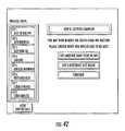
- the PChas a look up table that lists a range of blind sizes that are valid for any given stock size blind. A comparison is made between the entered desired size and the range of valid sizes. If the desired size falls within this range, the cut is validated and the user is asked to confirm the request. In the embodiment of FIG. 20 the PC then sends a signal to the PLC to initiate the cutting operation. In the embodiment of FIG. 19 the CPU initiates the cutting operation. If the desired size is outside of this range, an error message is displayed on the touch screen. If the user input data is not valid, an error message will be displayed to the user by the user interface identifying the error and requesting that the user correct the user input data or the selected window covering (Block 903 ). If the window covering/package 200 is provided with marks 103 that are readable by sensors 105 that prevent a cut if the cut would interfere with the components or functionality of the window covering as previously described, this separate verification step may be omitted.
- the CPUmay also compare the user input data to the product identification information from the bar code 220 and determine if the user has actually selected the window covering that the user believes that he or she selected (e.g. does the user input style and color match the actual style and color of the window covering) (Block 904 ).
- the displaymay display the information obtained from the look-up table for user review. If the user input data is valid for the selected blind, the SIS machine will initiate the cutting process to automatically cut the blind to the user's desired size as has been described (Block 905 ). If the user input data is not valid, an error message will be displayed to the user by the user interface identifying the error and requesting that the user correct the user input data or the selected window covering (Block 903 ). The validation process may be repeated until the user data is validated for the selected window covering. Note, one or both of verification steps 902 and 904 may be omitted.
- Another method for determining the validity of the window covering size determinationis to rely on the weight of the window covering rather than using a machine readable data structure such as bar code 220 .
- a scalecould be incorporated into the platform 20 to detect the weight of the window covering/package 200 .
- a look up in a look up table stored in memory 104can then be performed by the CPU 102 or processor 202 comparing the measured weight to the known weights of the stock window coverings.
- the weightcould be used to identify window covering characteristics such as permissible of cut ranges, window covering material or the like where the characteristics are used to validate or implement the cutting operation. For example a particular saw blade type or saw speed may be used for different blind materials. Further, valid cut ranges may be determined for a window covering.
- drive 89moves the clamp assembly 80 and the window covering/package 200 to the center position CP (Block 724 , FIG. 24D ).
- Drive 43retracts the clamping jaw 82 to releases the window covering/package 200 (Block 725 ).
- the systemmay then verify that the actual cut length matches the user input cut size (Block 726 ).
- the clamp assembly 80is moved along the platform 20 by drive 89 from the known center position in one direction until the sensor locates the first end 200 a of the window covering/package 200 .
- the direction of movement of the clamp assembly 80is then reversed and the clamp assembly 80 is moved along the platform 20 by drive 89 in the opposite direction until the sensor locates the opposite edge 200 b of the window covering/package.
- the distance the clamp assembly 80 travels between the two edges 200 a and 200 b of the packageis detected.
- the distance traveledis equal to the actual cut size of the window covering.
- the actual cut sizeis compared to the desired cut size input by the user. If the two sizes match the cut is verified.
- the two sizesmay be determined to match if the distance between the input cut size and the actual cut size fall within a predetermined minimum acceptable error margin.
- the vacuum, saws and other moving componentsare stopped and the door 6 or drawer 4302 are opened automatically or manually (Block 727 ).
- the cut window coveringcan then be removed by the user.
- the cutting operationis completely automated.
- the cutting processis also isolated from the user during the process to maximize the safety of the process.
- the data related to the transactionis stored in a transaction record 230 and may include, but not be limited to, original size of product, cut to size of product, date, time, store identifier/location, and blind drop (length), bar code number, product cut width, time spent during cutting, number of times the user navigates to each screen page and any errors reported by the PLC (Block 728 ).
- the data captured by the SIS machinecould be transferred to the blind manufacturer 111 or retailer outlet system 113 over a network 108 at any time and be associated with the customer's original order such that a complete record of the order and cutting operation is maintained (Block 729 ).
- FIGS. 28A and 28BNumerous processes may be used to enable the user to transmit the user input data to the SIS machine 1 .
- the usermeasures the window or other architectural feature using traditional measuring tools such as a tape measure, ruler, electronic tape measure or the like and notes the measurements (Block 801 ).
- the customerlogs onto a website of a window covering provider and selects a window covering product for each measured architectural feature and the selection is transmitted to and received by CPU 102 or processor 202 (Block 802 ).
- the usermay log onto the web site from a user terminal 109 or from user interface 112 or from any device that allows access to the website.
- a transaction recordis created for that customer and transaction by CPU 102 or processor 202 and the transaction record is stored in memory (Block 803 ).
- the customerenters a cut size for each of the selected window coverings and the CPU 102 or processor 202 receives the cut sizes (Block 804 ).
- the customeris prompted for and transmits whether the mount is an inside mount or an outside mount.
- the type of mountis received by the CPU 102 or processor 202 (Block 805 ). If outside mount is selected the window covering is cut to the size input by the customer. If inside mount is selected a length deduction, for example 1 ⁇ 2 % inch, is subtracted from the size input by the customer (Block 806 ).
- the customeris prompted for zip code, address or other geographical information and the geographical information is received by the CPU 102 or processor 202 (Block 807 ).
- the CPU 102 or processor 202determines the nearest retail outlet location having a SIS machine such as by using a look up table stored in memory 104 (Block 808 ).
- the identified retail outletis displayed on the user interface 112 or terminal 109 (Block 808 ).
- the customermay select the identified outlet or the customer may manually select another outlet.
- the selected outletis recorded in the transaction record (Block 809 ).
- the customeris prompted for and confirms the order and the confirmation is received by the CPU or processor (Block 810 ). Payment may be made on-line or payment may be deferred until the customer picks up the order at the retail outlet.
- the ordering processmay include verification of the customer payment information (Block 811 ).
- the customer's order and/or complete transaction recordis sent to the selected retail outlet 113 over network 108 (Block 812 ).
- the retail outlet personneluse the SIS machine to cut the ordered window coverings to the customer's specified dimensions (Block 813 ) as previously described.
- the cutting operationmay be performed during off hours or non-peak hours to more efficiently use personnel time.
- the customeris contacted by retail outlet 113 with a scheduled pick-up time for retrieving the cut window covering (Block 814 ).
- the customertravels to the retail outlet to pick up the cut window coverings (Block 815 ).
- Another ordering methodologyuses a photo-measuring kit to provide the measurements for the architectural feature rather than using a traditional measuring tool.
- the customerobtains a photo-measuring kit such as by ordering a kit from a window covering manufacturer's website or picking up a measuring kit at a retail outlet.
- the measuring kitincludes at least one measuring block 120 that includes a unique design 121 printed on a front surface thereof (Block 601 ).
- the measuring blockmay comprise any rigid material that can be supported adjacent the architectural feature 123 being measured.
- the design 121comprises a unique pattern or design that is of known dimensions and shape. The specific shape of the design is selected such that it is unlikely to be similar to any aspects of the architectural feature and thus will be recognizable when viewed adjacent to the architectural feature.
- the customerplaces one or more measuring blocks 120 in the architectural feature being measured (Block 602 ) such that the measuring block 120 and entire architectural feature 123 are visible.
- the measuring block 120should be mounted as close to the same plane as the architectural feature being measured.
- the measuring blockis mounted within the frame of the window such as by taping it to the window glass.
- at least two measuring blocksare used where each measuring block is located with a designated edge 125 placed along the edge of the architectural feature being measured.
- the edges 125 of the blocks 120are placed along the inside frame of the window.
- a digital photograph of the architectural feature 123 with the measuring blocks 120 mounted adjacent theretois taken (Block 604 ).
- the customermay also place a unique designator 127 on the architectural feature while photographing it to identify the building, room and/or architectural feature to which that measurement relates (Block 603 ).
- the customerlogs onto a window covering provider website from a user terminal 109 over network 108 and the CPU 102 or processor 202 creates a transaction record (Block 605 ).
- the systemprompts the customer for, and the customer enters, information related to the customer such as name, address, payment information, internet address or the like and the CPU 102 or processor 202 receives this information and populates the transaction record unique to that customer and transaction (Block 606 ).
- the customeris then prompted to upload the photographs taken of the architectural feature with the measuring blocks (Block 607 ).
- the customeruploads the photographs and the photographs are received by the CPU 102 or processor 202 and stored in memory (Block 608 ).
- the photographsare displayed to the customer on the customer interface 112 109 (Block 609 ).
- the customeris prompted to select the photograph of the first architectural feature for which a window covering is to be ordered (Block 610 ).
- the customer selectionis entered into the transaction record for the first transaction (Block 611 ).
- the systemdetermines the dimensions of the architectural feature using the photograph provided and selected by the user (Block 612 ). Referring to FIG. 31 , the system first determines the display resolution of the photograph (Block 1201 ). Once the display resolution is determined the system determines the scale of the photograph (Block 1202 ). This is accomplished by counting the number of pixels extending from one point on the unique design 121 on a measuring block to another point on that design (Block 1203 ). Because the dimensions of the design 121 are known, the system can determine the scale of the photograph by calculating how many pixels extend between the two points on the design. Because the distance between the two known points is known the system calculates how much linear distance (scaling factor) each pixel represents (Block 1204 ).
- the systemcan then determine the distance between the reference edges 125 of the measuring blocks 120 by counting the pixels between those reference edges (Block 1205 ) and multiplying the number of pixels by the scaling factor (Block 1206 ). Thus, the system can automatically determine the dimension of the architectural feature based on the photograph provided by the user.
- the customeris then prompted to select a cut-to-size window covering for the selected architectural feature and the selection is received and stored by the CPU 102 (Block 613 ).
- the systemautomatically overlays the selected window covering on the selected architectural feature and displays the composite image on the user terminal 109 (Block 614 ).
- the composite imageprovides the customer an opportunity to view how a specific window covering will look on their specific architectural feature before the customer purchases the window covering.
- the customercan change the style, color, mount of the window covering to display various design options before purchasing the window covering.
- the customerselects the desired window covering and the selection is received and recorded by CPU 102 (Block 615 ).
- FIG. 32the customer visits a retail outlet having a SIS machine (Block 1001 ).
- the customerphysically shops the retail outlet and selects the window covering they wish to purchase and cut (Block 1002 ).
- the customer or store personnel(hereinafter “user”) loads the selected window covering into the SIS machine and initiates the cutting process by pushing a start button on the user interface 112 (Block 1003 ).
- the useruses user interface 112 to input information about the SIS product to be sized and the customer.
- a sample screen shotis shown in FIG.
- FIG. 34that illustrates an introductory screen that may be displayed on user interface 112 that provides the user with options to cut the window covering, instructions on how to use the system, or the like. If the user selects to cut a blind another screen shot such as that shown in FIG. 35 may be presented on user interface 112 that prompts the user for information relating to the window covering to be cut. In the illustrated screen shot the user is prompted to select a type of blind. The information is received by the CPU 102 or processor 202 and a transaction record is created (Block 1004 ). Verbal and/or visual feedback on the selection may be given to the user at user interface 112 .
- a sample screen shotis shown in FIG. 36 for receiving the size information from the customer.
- Another screen shotis shown in FIG. 37 showing a pop up screen for receiving the user measurements of the architectural feature.
- the useris prompted for and enters into the system inside or outside mount and the CPU 102 or processor 202 receives and records this information in the transaction record (Block 1006 ).
- a sample screen shotis shown in FIG. 38 for receiving the inside/outside mount information.
- the systemdetermines and displays on the user interface the size of the stock product required for the desired cut product (Block 1007 ).
- a sample screen shotis shown in FIG.
- FIG. 40A sample screen shot is shown in FIG. 40 prompting the user to load the machine and for displaying a signal that the window covering was properly inserted.
- the user interface 112may display to the user a summary of the data related to the window covering including size, blind type, color or the like as shown in the screen shot of FIG. 41 .
- the machineautomatically cuts the blind to the desired size as previously explained. The process may be repeated for each blind to be cut.
- a screen shot prompting the user for another window covering or ending the cutting sessionis illustrated in FIG. 42 .
- the SIS machinemay print a receipt containing the original size of the product before cutting, and the size the product have cut too.
- Data of the transactionwould be stored in the internal database 104 where the stored data may include, but not be limited to, original size of product, cut to size of product, date, time, store location, and blind drop.
- the data captured by the SIS machinecould be transferred to the blind manufacturer 111 or retailer outlet system 113 over network 108 at any time such that a complete record of the order and cutting operation is maintained as previously described.
- the informationmay be remotely provided from any of these entities to and from the SIS machine.
- the SIS machinemay provide a maintenance alert if its onboard diagnostics determines that that a predetermined situation has occurred.
- the SIS machinemay also provide diagnostic information to a maintenance service provider.
- the software running the SIS machinecan also be remotely updated to change operating parameters of the machine such as the feed speed and rotational speed of the saws.
- the software running the SIS machinecan also be remotely updated to change the information displayed on the screen to the user including sales and marketing information.
- FIG. 33Another ordering methodology uses the photo-measuring kit as previously described.
- the userphotographs the architectural feature 123 and blocks 120 using a digital camera (Block 1101 ).
- the userbrings the camera or memory stick or the like having the photographs stored in memory to a retail outlet and connects the camera to the CPU 102 or processor 202 via a USB port or places the memory stick in the appropriate memory card reader slot or otherwise connects the camera memory to the CPU 102 or processor 202 (Block 1102 ).
- the customerinputs information to the user interface and the CPU 102 or processor 202 creates a transaction record as previously described (Block 1103 ).
- Overlay imagesmay be displayed at user interface 112 such that the customer can view the images of selected window coverings on their photographs and select a desired window covering style as previously described (Block 1104 ).
- the CPU 102 or processor 202calculates the stock size of the window covering and displays to the user the size of stock window covering that is needed for the architectural feature shown in the user photograph ( 1105 ).
- Another ordering methodologyrequires that the customer manually measure the dimensions of the architectural feature to be covered using existing measuring tools such as a tape measure or laser measure (Block 1106 ).
- the customerbrings the measurements to a retail outlet and manually inputs the measurement information and other information at the user interface 112 and the CPU 102 or processor 202 and a transaction record is created as previously described (Block 1107 ).
- the CPU 102 or processor 202calculates the required stock window covering size (Block 1105 ).
- the userthen physically selects the indicated window covering from the retail outlet inventory and places the window covering in the SIS machine as previously described (Block 1108 ).
- the SIS machineoperates automatically to cut the window covering to the desired size as previously explained.
- the SIS systemcould direct the customer to the appropriate size window coverings (Block 1109 ).
- the user interface 112displays an identification of the location within the retail outlet by alphanumeric characters, color code, map or the like (Block 1110 ).
- the systemmay be connected to lights or other audio/visual indicators 135 associated with the inventory of window coverings where the indicator is actuated to identify the appropriate window covering (Block 1111 ).
- the bin in which the window coverings are storedis lighted to guide the customer to the appropriate window covering.
- This informationcan be used to confirm and verify individual purchases by individual purchasers. This information can also be used in the aggregate to determine market trends, most common window sizes, most popular window treatments, buying habits and other market trends. This information may also be used for inventory control. For example, if the window covering provider has access to the data that manufacturer can obtain real time information on hand inventory for any of its customers and can restock depleted inventory and/or remove slow moving inventory in a timely manner to ensure that the manufacturer's supply of product matches the purchasing patterns of a specific retailer's customers. The retail outlet, if it has access to this information, can use the information for its own customers. All of this data may be sent to a remote location over network 108 .
- the user interface 112can be used to present advertising information, news, or other information to the customer.
- the informationmay be stored locally in the operating system of the SIS machine such that the information relates to other products sold by the retail outlet or window covering provider.
- the operating system of the SIS machineis connected to the internet, any information may be provided on the user interface by the system administrator where the user interface 112 functions as the user terminal.
Landscapes
- Engineering & Computer Science (AREA)
- Mechanical Engineering (AREA)
- Structural Engineering (AREA)
- Architecture (AREA)
- Civil Engineering (AREA)
- Sawing (AREA)
Abstract
Description
Y=Final Dimension−Z+C,
where Y is the distance between the alignment hole and the saw (Block5014). The final dimension of the vertical window covering is Y+Z−C.
Claims (24)
Priority Applications (5)
| Application Number | Priority Date | Filing Date | Title |
|---|---|---|---|
| US12/838,946US9427813B2 (en) | 2007-07-31 | 2010-07-19 | Window covering sizing method and apparatus |
| CA2746780ACA2746780C (en) | 2010-07-19 | 2011-07-18 | Window covering sizing method and apparatus |
| CA3079490ACA3079490C (en) | 2010-07-19 | 2011-07-18 | Window covering sizing method and apparatus |
| CA2990127ACA2990127C (en) | 2010-07-19 | 2011-07-18 | Window covering sizing method and apparatus |
| US15/241,515US10639729B2 (en) | 2007-07-31 | 2016-08-19 | Window covering sizing method and apparatus |
Applications Claiming Priority (4)
| Application Number | Priority Date | Filing Date | Title |
|---|---|---|---|
| US96264607P | 2007-07-31 | 2007-07-31 | |
| US1029108P | 2008-01-07 | 2008-01-07 | |
| US12/164,839US7987754B2 (en) | 2007-07-31 | 2008-06-30 | Window covering sizing method and apparatus |
| US12/838,946US9427813B2 (en) | 2007-07-31 | 2010-07-19 | Window covering sizing method and apparatus |
Related Parent Applications (1)
| Application Number | Title | Priority Date | Filing Date |
|---|---|---|---|
| US12/164,839Continuation-In-PartUS7987754B2 (en) | 2007-07-31 | 2008-06-30 | Window covering sizing method and apparatus |
Related Child Applications (1)
| Application Number | Title | Priority Date | Filing Date |
|---|---|---|---|
| US15/241,515ContinuationUS10639729B2 (en) | 2007-07-31 | 2016-08-19 | Window covering sizing method and apparatus |
Publications (2)
| Publication Number | Publication Date |
|---|---|
| US20110056353A1 US20110056353A1 (en) | 2011-03-10 |
| US9427813B2true US9427813B2 (en) | 2016-08-30 |
Family
ID=43646648
Family Applications (2)
| Application Number | Title | Priority Date | Filing Date |
|---|---|---|---|
| US12/838,946Active2030-01-08US9427813B2 (en) | 2007-07-31 | 2010-07-19 | Window covering sizing method and apparatus |
| US15/241,515Active2029-02-14US10639729B2 (en) | 2007-07-31 | 2016-08-19 | Window covering sizing method and apparatus |
Family Applications After (1)
| Application Number | Title | Priority Date | Filing Date |
|---|---|---|---|
| US15/241,515Active2029-02-14US10639729B2 (en) | 2007-07-31 | 2016-08-19 | Window covering sizing method and apparatus |
Country Status (1)
| Country | Link |
|---|---|
| US (2) | US9427813B2 (en) |
Cited By (2)
| Publication number | Priority date | Publication date | Assignee | Title |
|---|---|---|---|---|
| US10521089B2 (en) | 2014-02-27 | 2019-12-31 | Hunter Douglas Inc. | Apparatus and method for providing a virtual decorating interface |
| US20220314348A1 (en)* | 2021-04-06 | 2022-10-06 | Lisheng Yu | Dustless miter saw |
Families Citing this family (10)
| Publication number | Priority date | Publication date | Assignee | Title |
|---|---|---|---|---|
| US20070239551A1 (en)* | 2006-03-30 | 2007-10-11 | Zeller Michelle G | Method and apparatus for a product ordering system |
| US8322260B2 (en) | 2007-07-31 | 2012-12-04 | Newell Window Furnishings, Inc. | Window covering sizing method and apparatus |
| US8839701B2 (en) | 2007-07-31 | 2014-09-23 | Newell Window Furnishings, Inc. | Window covering sizing method and apparatus |
| US8256333B2 (en)* | 2007-07-31 | 2012-09-04 | Newell Window Furnishings, Inc. | Window covering sizing method and apparatus |
| US7987754B2 (en) | 2007-07-31 | 2011-08-02 | Newell Window Furnishings, Inc. | Window covering sizing method and apparatus |
| CN107210053B (en)* | 2015-01-30 | 2020-08-21 | 松下知识产权经营株式会社 | Recording medium handling device |
| WO2020221410A1 (en)* | 2019-05-01 | 2020-11-05 | Kobots Aps | A portable automatic panel cutter and a method for marking panel parts |
| CN110695441B (en)* | 2019-09-25 | 2020-12-08 | 湖州达立智能设备制造有限公司 | Intelligent pipeline cutting robot capable of rolling in annular mode and achieving continuous incision |
| CN112659216A (en)* | 2020-12-22 | 2021-04-16 | 深圳市金昊晟光电有限公司 | Die cutting and plate cutting device for printed matter and using method thereof |
| EP4596154A1 (en)* | 2024-01-31 | 2025-08-06 | SCM Group S.p.A. | Sawing machine |
Citations (222)
| Publication number | Priority date | Publication date | Assignee | Title |
|---|---|---|---|---|
| US239691A (en) | 1881-04-05 | Leonard | ||
| US265635A (en) | 1882-10-10 | Michael eattghtigan and albeet a | ||
| US397475A (en) | 1889-02-05 | tiffany | ||
| US421027A (en) | 1890-02-11 | Machine for sawing and drilling metal or other substances | ||
| US702200A (en) | 1901-06-10 | 1902-06-10 | J J T Reese | Lumber-measure. |
| US866243A (en) | 1906-08-06 | 1907-09-17 | Gustav Waechter | Graduated food-package. |
| US1038920A (en) | 1912-01-19 | 1912-09-17 | Adolf J Marschall | Rennet-package and method of making same. |
| GB121338A (en) | 1917-12-11 | 1918-12-11 | Bertram Warren Elliott | An Improved Elevator or Load-raising Device. |
| US1382433A (en) | 1919-10-03 | 1921-06-21 | Defiance Machine Works | Independent feed rail drill |
| US1481700A (en) | 1922-12-08 | 1924-01-22 | Severt M Fatland | Method of dispensing ice cream |
| US1647254A (en) | 1922-11-09 | 1927-11-01 | United Shoe Machinery Corp | Cutting sheet material |
| US1721276A (en) | 1927-09-26 | 1929-07-16 | Products Machine Company | Die-shearing press |
| US1792522A (en) | 1929-10-17 | 1931-02-17 | Buffalo Forge Co | Shearing machine |
| US1924162A (en) | 1930-10-18 | 1933-08-29 | Masonite Corp | Cut-off machine |
| US1952698A (en) | 1933-06-12 | 1934-03-27 | Stack Goble Advertising Agency | Butter |
| US2044481A (en) | 1934-12-08 | 1936-06-16 | Western Electric Co | Material working machine |
| US2057488A (en) | 1936-01-02 | 1936-10-13 | Frederick I Hochstadt | Apparatus for use with type slug saws |
| US2077697A (en) | 1936-04-22 | 1937-04-20 | Reynolds Metals Co | Method of packing cheese |
| US2120593A (en) | 1936-12-09 | 1938-06-14 | Columbia Mills Inc | Method of wrapping venetian blinds |
| US2159997A (en) | 1937-12-15 | 1939-05-30 | Alberta J Millar | Quantity indicating wrapper |
| US2234013A (en) | 1938-06-10 | 1941-03-04 | Stover Russell | Frozen confection, container therefor, and method of removing contents |
| US2247314A (en) | 1939-05-31 | 1941-06-24 | Gilbert J Sellmeyer | Portable power driven saw |
| US2265707A (en)* | 1940-09-09 | 1941-12-09 | James L Wall | Pneumatic conveyer separator device |
| US2418515A (en) | 1944-12-08 | 1947-04-08 | Clark T Collins | Method and apparatus for measuring and manufacturing venetian blinds |
| DE857677C (en) | 1950-02-01 | 1952-12-01 | Erhard Noack | Containers for the storage and display of goods and for similar purposes |
| US2631508A (en) | 1948-09-24 | 1953-03-17 | Bendix Aviat Corp | Web pleating and cutting machine |
| US2644520A (en) | 1949-12-09 | 1953-07-07 | Lorentzen Hardware Mfg Corp | Length cutting machine |
| US2691994A (en) | 1951-08-22 | 1954-10-19 | Glenn D Ferguson | Hydraulically actuated planetary gearing for sawmill feed works |
| US2747625A (en) | 1954-11-12 | 1956-05-29 | Atkins Ind Inc | Block-and-tape lumber measuring device for bench saws |
| US2789639A (en) | 1950-09-09 | 1957-04-23 | Lorentzen Hardware Mfg Corp | Method useful in the manufacture of venetian blinds |
| US2806493A (en) | 1954-02-05 | 1957-09-17 | King Seeley Corp | Work guide fence |
| US2827686A (en) | 1953-09-15 | 1958-03-25 | Adelman Harry | Method and apparatus for assembling venetian blinds |
| US2883736A (en) | 1955-09-12 | 1959-04-28 | Continental Machines | Band type cutoff saw |
| US2949943A (en) | 1958-05-14 | 1960-08-23 | Islandsrud Ola | Table saw with means for tilting and reciprocating |
| US2987085A (en) | 1958-08-01 | 1961-06-06 | Burke E Porter Machinery Co | Automatic sequencing wood saw and clamp |
| US3260146A (en) | 1964-11-30 | 1966-07-12 | Canada Steel Co | Double head side trimmer |
| US3263544A (en) | 1964-09-01 | 1966-08-02 | David H Margolien | Elongated stock cutting apparatus |
| US3292232A (en) | 1963-09-24 | 1966-12-20 | Nilsson Erik Gunnar | Method and apparatus for assembling venetian blinds |
| US3391591A (en) | 1965-01-12 | 1968-07-09 | Peddinghaus Paul Ferd | Profile iron shears |
| US3470926A (en) | 1967-01-30 | 1969-10-07 | Dohm & Nelke Inc | Hydraulic slicing machine control |
| US3513740A (en) | 1967-04-03 | 1970-05-26 | George L Burghart | Cutting device for cleats and other shaped structurals |
| US3521810A (en) | 1968-06-21 | 1970-07-28 | Hoerner Waldorf Corp | Variable size container |
| US3564893A (en) | 1968-02-05 | 1971-02-23 | Selva & Sons Ltd E | Combined cutting,punching and bending tool |
| US3584380A (en) | 1968-10-17 | 1971-06-15 | U S Photographic Equipment Cor | Opener device for photographic film cartridges |
| US3618297A (en) | 1969-07-22 | 1971-11-09 | Jet Line Products Inc | Vacuum pickup apparatus |
| US3634975A (en) | 1968-05-28 | 1972-01-18 | Carborundum Co | Sawing apparatus |
| US3640023A (en)* | 1969-08-19 | 1972-02-08 | Abrasive Dev | Abrading machines |
| US3664221A (en) | 1969-05-07 | 1972-05-23 | Intermenua Pty Ltd | Shearing machines |
| US3677117A (en) | 1969-06-09 | 1972-07-18 | James W Cutter | Material cutting apparatus with reciprocating cutting elements |
| US3715946A (en) | 1970-09-17 | 1973-02-13 | D Kaltenbach | Feed control apparatus for a rotary tool |
| US3736631A (en) | 1970-09-04 | 1973-06-05 | Douglas H Int Nv | Ladder mechanism for an assembling apparatus for the manufacture of completely or partly finished packages of slats for venetian blinds |
| US3750509A (en) | 1972-05-17 | 1973-08-07 | Peddinghaus W | Profile steel cutter |
| US3766815A (en) | 1971-01-08 | 1973-10-23 | Hunter Douglas International | Apparatus for forming strip |
| US3910142A (en) | 1971-02-05 | 1975-10-07 | Automated Building Components | Automated saw |
| US4018188A (en) | 1975-06-10 | 1977-04-19 | James Reuben Burdette | Reinforced concrete slat floor |
| US4036092A (en) | 1974-11-08 | 1977-07-19 | Dieter Kaltenbach | Table-mounted circular saw |
| US4055206A (en) | 1975-05-14 | 1977-10-25 | Griffin Carl W | Composite shop trailer |
| US4067252A (en) | 1975-06-06 | 1978-01-10 | Rolf Peddinghaus | Machine tool with cylindrical assembly units |
| US4139043A (en) | 1977-03-10 | 1979-02-13 | Joanna Western Mills Company | Window shade slat |
| US4151768A (en) | 1978-05-04 | 1979-05-01 | Shockovsky Robert E | Apparatus and method for forming templates |
| US4188693A (en) | 1976-09-30 | 1980-02-19 | Hunter Douglas International N.V. | Method and apparatus for assembling slatted blinds |
| US4201256A (en)* | 1979-01-10 | 1980-05-06 | Andrew Truhan | Sawdust collector |
| US4214493A (en) | 1977-02-15 | 1980-07-29 | Elhaus Freidrich W | Circular saw |
| US4227305A (en) | 1979-03-12 | 1980-10-14 | Newman Jerry C | Hand tool for cutting blind strips and the like |
| US4227902A (en) | 1977-08-08 | 1980-10-14 | St. Charles Manufacturing Co. | Bench structure with dust collector |
| US4230005A (en) | 1978-01-02 | 1980-10-28 | Ferenc Varga | Traveling circular saw |
| US4233782A (en) | 1979-06-21 | 1980-11-18 | Ronald Perrault | Work cabinet for podiatrists, dentist and the like |
| US4262564A (en) | 1978-07-07 | 1981-04-21 | Dieter Kaltenbach | Method of and a device for the elimination of play in feeding means of a cold-action circular saw |
| US4270253A (en) | 1978-04-20 | 1981-06-02 | Trumpf America, Inc. | Apparatus for simultaneous machining of a stack of plate-like workpieces |
| US4326864A (en) | 1980-08-08 | 1982-04-27 | Sittler Werner G | Apparatus for and method of collecting sawdust particles |
| US4338710A (en) | 1980-02-20 | 1982-07-13 | Stursa Ken V | Apparatus for forming bores |
| US4367665A (en) | 1980-12-19 | 1983-01-11 | Emerson Electric Co. | Sawdust collection system |
| US4407614A (en) | 1977-12-30 | 1983-10-04 | Muhr Und Bender | Apparatus for perforating a workpiece |
| US4457197A (en) | 1981-02-26 | 1984-07-03 | Rolf Peddinghaus | Device for cutting and/or stamping metal bars and sections |
| US4468995A (en) | 1982-01-11 | 1984-09-04 | Cuprum, S.A. | Apparatus for manufacturing frames from aluminum profile rails |
| US4492301A (en) | 1981-06-30 | 1985-01-08 | Fujitsu Fanuc Limited | Workpiece feeder |
| US4545100A (en) | 1982-07-23 | 1985-10-08 | Hunter Douglas International N.V. | Method and apparatus for manufacturing venetian blinds |
| US4567930A (en) | 1983-05-20 | 1986-02-04 | Newell Companies, Inc. | Consumer-adjustable mini-blind |
| US4576072A (en) | 1981-10-16 | 1986-03-18 | Emerson Electric Co. | Sawdust collection apparatus for a table saw |
| US4589312A (en) | 1984-02-22 | 1986-05-20 | Joanna Western Mills Company | Automatic shade cutter |
| US4589313A (en) | 1985-05-30 | 1986-05-20 | Joanna Western Mills Company | Automatic shade cutter |
| US4606099A (en) | 1983-03-24 | 1986-08-19 | Griesser Ag | Method and apparatus for manufacturing an armor shutter |
| US4619166A (en) | 1985-01-25 | 1986-10-28 | Colic Machine & Tool Limited | Double-bladed power hacksaw |
| US4625868A (en) | 1984-02-23 | 1986-12-02 | Emil Schenker Ag | Composite slat for use in venetian blinds |
| US4639987A (en) | 1985-04-19 | 1987-02-03 | Levolor Lorentzen, Inc. | Apparatus for producing simultaneously a plurality of Venetian blinds |
| US4726273A (en) | 1986-11-20 | 1988-02-23 | Miceli John P | Combination press for die-sets |
| US4730372A (en) | 1985-08-21 | 1988-03-15 | Tachikawa Corporation | Apparatus for fabricating blind |
| EP0265564A1 (en) | 1986-10-30 | 1988-05-04 | Teh Yor Industrial Co. Ltd. | Apparatus to trim an assembled venetian blind to a given length |
| EP0273535A1 (en) | 1987-01-02 | 1988-07-06 | Teh Yor Industrial Co. Ltd. | Apparatus to trim an assembled venetian blind to a given length |
| US4771667A (en) | 1986-09-02 | 1988-09-20 | Metl-Saw System Inc | Precision metal cutting saw and assembly |
| US4776096A (en) | 1986-12-29 | 1988-10-11 | Chang A Shien | Scissors means particularly for cutting blind's slats |
| US4790226A (en) | 1985-12-24 | 1988-12-13 | Tachikawa Corporation | Apparatus for cutting blind slats |
| US4807363A (en) | 1987-03-05 | 1989-02-28 | Clifton Jr Thomas S | Apparatus for trimming venetian blinds |
| US4819530A (en) | 1986-10-24 | 1989-04-11 | Teh Yor Industrial Co., Ltd. | Apparatus and method for trimming a venetian blind assembly |
| US4823449A (en) | 1987-11-09 | 1989-04-25 | Chang A Shen | Automatic and continuous mechanism for processing and assembling venetian blind slats |
| US4876795A (en) | 1988-08-01 | 1989-10-31 | Teh Yor Industrial Co., Ltd. | Cutter, in particular for a slat, especially of a venetian blind |
| US4901419A (en) | 1989-01-03 | 1990-02-20 | Home Fashions, Inc. | A-frame window covering mounting arrangement |
| US4907337A (en) | 1986-11-04 | 1990-03-13 | Kruesi Fritz | Apparatus for machining a workpiece of wood, in particular wood beams |
| US4907325A (en) | 1988-08-09 | 1990-03-13 | Hsu Pei H | Blind trimmer |
| US4924740A (en) | 1987-11-10 | 1990-05-15 | Emhart Industries, Inc. | Adjustable mounting for multigob apparatus for straight line shearing |
| US4928369A (en) | 1988-06-20 | 1990-05-29 | Comfortex Corporation | Method of making a pleated blind with articulative slat extensions |
| US4987765A (en) | 1988-11-25 | 1991-01-29 | Hashimoto Forming Industry Co., Ltd. | Method and apparatus for multi-step workpiece manufacturing |
| US4993131A (en) | 1988-08-19 | 1991-02-19 | Newell Operating Company | Method and apparatus of infinitely sizing a mini blind |
| USD316979S (en) | 1988-06-08 | 1991-05-21 | Reynolds Billy D | Combined ruler and compass |
| US5037253A (en) | 1989-12-04 | 1991-08-06 | Levolor Corporation | Apparatus for making Venetian blinds |
| US5054206A (en) | 1989-04-14 | 1991-10-08 | Carlson Robert A | Chain saw projection mensuration method and apparatus for determining the diameter of trees |
| US5056388A (en) | 1990-01-22 | 1991-10-15 | Hunter Douglas International N.V. | Blind cutting machine |
| US5060709A (en) | 1989-10-10 | 1991-10-29 | Newell Co. | Infinitely sizable solid slat mini blind |
| US5072494A (en) | 1988-08-19 | 1991-12-17 | Newell Operating Company | Method and apparatus of infinitely sizing a mini blind |
| US5103702A (en) | 1988-12-21 | 1992-04-14 | Levolor Lorentzen, Inc. | Method of cutting slats for a venetian blind |
| US5119854A (en) | 1989-06-19 | 1992-06-09 | Albadecor S.A. | Compact and ergonomic picture-framing unit |
| GB2258686A (en) | 1991-07-08 | 1993-02-17 | Newell Operating Co | Pleated shade |
| US5215512A (en) | 1990-04-26 | 1993-06-01 | Bobst Sa | Blank separating tools changing table |
| US5251382A (en) | 1991-02-28 | 1993-10-12 | Baklund-Hellar, Inc. | Tape measure for determining the centerpoint of a distance |
| US5302228A (en)* | 1991-04-11 | 1994-04-12 | David Holland | Apparatus and method for making V-groove insulation and tank wrap |
| US5339716A (en) | 1993-02-22 | 1994-08-23 | Newell Operating Co. | Mini blind cutter |
| US5349730A (en) | 1993-03-09 | 1994-09-27 | Hunter Douglas Inc. | Mehtod and apparatus for assembling blinds |
| EP0629475A1 (en) | 1993-06-15 | 1994-12-21 | Robotec Consulting AG | Articulated arm for manipulators and industrial robots |
| US5392524A (en) | 1993-06-11 | 1995-02-28 | Masco Corporation Of Indiana | Apparatus for aligning handle valves during installation of a faucet |
| US5456149A (en) | 1993-02-18 | 1995-10-10 | Newell Operating Co. | Sizing system for window coverings |
| CA2136519A1 (en) | 1994-11-23 | 1996-05-24 | Chung-Chen Huang | Cutting apparatus for venetian blind |
| US5667152A (en) | 1995-05-30 | 1997-09-16 | Mooring; Jonathan E. | Safety system for a wood chipper |
| US5740053A (en) | 1995-07-31 | 1998-04-14 | Tokyo Electron Limited | Method of controlling monitor used in cleaning machine and object processing machine and monitor apparatus |
| US5787774A (en) | 1994-10-28 | 1998-08-04 | Hem, Inc. | Bandsaw apparatus with pivotally-mounted saw head assembly arm and method |
| US5799557A (en) | 1997-03-19 | 1998-09-01 | Wang; Cherng-Fa | Venetian blind cutting machine |
| US5806245A (en) | 1996-01-16 | 1998-09-15 | Satrom; James P. | Vertical lift gate assembly |
| US5806394A (en) | 1995-09-11 | 1998-09-15 | Shade-O-Matic Limited | End trimming device for blinds |
| US5816126A (en) | 1996-02-02 | 1998-10-06 | Holis Metal Industries, Ltd. Israeli Co. | Cutter for shortening blinds |
| US5819619A (en) | 1991-10-09 | 1998-10-13 | Black & Decker Inc. | Dust collection system for compound miter saw |
| US5826317A (en) | 1995-12-14 | 1998-10-27 | Hunter Douglas International N.V. | System for manufacturing blinds |
| US5882155A (en) | 1994-12-22 | 1999-03-16 | Testa, Jr.; Vincent M. | Ceiling tile cutting apparatus |
| US5927172A (en) | 1998-01-21 | 1999-07-27 | Wang; Cherng-Fa | Venetian blind cutting machine |
| US5943932A (en) | 1994-12-12 | 1999-08-31 | Black & Decker, Inc. | Bevel table saw adjustment |
| US5971839A (en) | 1998-04-11 | 1999-10-26 | Schmelzer; Hans | Dust containment vacuum system |
| US6003218A (en) | 1997-05-14 | 1999-12-21 | 3 Day Blinds, Inc. | Apparatus for cutting and assembling slats for window blind units |
| US6003217A (en) | 1991-07-08 | 1999-12-21 | Newell Operating Company | Size-in-store pleated shade and method and apparatus of sizing |
| US6079306A (en) | 1998-06-05 | 2000-06-27 | Liu; Tai-Ping | Cutting-off machine for a venetian blind |
| US6089134A (en) | 1999-07-23 | 2000-07-18 | Shade-O-Matic Limited | Multi blind trim machine |
| US6098694A (en) | 1999-01-19 | 2000-08-08 | Ohanesian; Harout | User-sizeable headrail assembly |
| US6142196A (en) | 1999-12-08 | 2000-11-07 | 3 Day Blinds, Inc. | Machine for forming bottom rail and valance of window blind unit |
| US6167789B1 (en) | 1997-07-25 | 2001-01-02 | Newell Operating Company | Dual mini-blind cutter |
| US6178857B1 (en) | 1995-09-11 | 2001-01-30 | Shade-O-Matic Limited | Method of end trimming of blinds |
| WO2001007747A1 (en) | 1999-07-23 | 2001-02-01 | Shade-O-Matic Limited | Rotary saw cutter blind cut down machine |
| WO2001010408A2 (en) | 1999-08-06 | 2001-02-15 | Bayer Aktiengesellschaft | Aqueous pharmaceutical composition containing moxifloxacin or salts thereof |
| US6196099B1 (en) | 1995-09-11 | 2001-03-06 | Shade-O-Matic Limited | End trimming apparatus for blinds |
| US6202014B1 (en) | 1999-04-23 | 2001-03-13 | Clark Equipment Company | Features of main control computer for a power machine |
| US6240824B1 (en) | 1999-07-14 | 2001-06-05 | Ching Feng /Blinds Ind. Co., Ltd. | Blind cutting machine |
| US6263945B1 (en) | 2000-01-19 | 2001-07-24 | Ming Nien | Venetian blinds |
| US6334379B1 (en) | 1998-02-26 | 2002-01-01 | Royal Window Coverings (Canada) Inc. | Mini-blind cut-down machine |
| US6336388B1 (en) | 1999-07-23 | 2002-01-08 | Shade-O-Matic Limited | Rotary saw cutter blind cut down machine |
| US6362893B1 (en) | 1998-03-06 | 2002-03-26 | Fargo Electronics, Inc. | Security printing and unlocking mechanism for high security printers |
| US6370997B1 (en)* | 1997-06-09 | 2002-04-16 | Elektra Beckum Ag | Transportable bench circular saw |
| US6405406B1 (en) | 2001-06-14 | 2002-06-18 | Peter Chen | Device capable of collecting and drawing dust |
| US6412381B1 (en) | 1999-12-16 | 2002-07-02 | Industrial Technology Research Institute | Venetian blind cutting machine |
| US6418762B1 (en) | 1998-01-19 | 2002-07-16 | Rittal-Werk Rudolf Loh Gmbh & Co., Kg | Switchgear cabinet closing device |
| US6427571B1 (en) | 2000-08-24 | 2002-08-06 | Ching Feng Blinds Ind. Co., Ltd. | Venetian blind cutting machine |
| US6435066B1 (en) | 1997-12-18 | 2002-08-20 | Springs Window Fashions Division, Inc. | Cutting apparatus for window covering and methods therefor |
| WO2002096586A1 (en) | 2001-05-30 | 2002-12-05 | Custom Craft Co. | Dual-end blinds trimming machine |
| US6500048B1 (en) | 1999-08-25 | 2002-12-31 | Sulzer Chemtech Ag | Method for separating profiled foils |
| WO2003010408A2 (en) | 2001-07-23 | 2003-02-06 | Newell Window Furnishings, Inc. | Blind and shade cutting center and method |
| US20030033919A1 (en) | 2001-08-15 | 2003-02-20 | Industrial Technology Research Institute | Venetian blind cutting machine having a plurality of interchangeable tools of various specifications |
| CA2355507A1 (en) | 2001-08-21 | 2003-02-21 | Industrial Technology Research Institute | Venetian blind cutting machine having a plurality of interchangeable tools of various specifications |
| US6535294B1 (en) | 1998-06-23 | 2003-03-18 | Discount Labels, Inc. | System and method for preparing customized printed products over a communications network |
| US20030066403A1 (en) | 2001-09-10 | 2003-04-10 | Industrial Technology Research Institute | Multi-module Venetian blind cutting machine |
| US6561121B1 (en) | 1998-11-28 | 2003-05-13 | Roper Industries Limited | Condition detecting apparatus |
| US6560849B1 (en) | 1998-04-15 | 2003-05-13 | Christopher Max Modra | Apparatus for manufacturing slats |
| US20030140756A1 (en) | 2002-01-16 | 2003-07-31 | Industrial Technology Research Institute | Venetian blind cutting machine |
| US6644160B1 (en) | 2001-04-12 | 2003-11-11 | William C. Boselli | Vertical blind cutting and hole-punching apparatus |
| US6688204B2 (en) | 2001-02-26 | 2004-02-10 | Shien-Te Huang | Cutting machine of dual blade feeding for blind of foamed plastics |
| US20040093682A1 (en)* | 2002-11-19 | 2004-05-20 | Ivan Litomisky | Energy saving vacuum system for particle, mist, and fume collection |
| US20040103767A1 (en) | 2002-11-29 | 2004-06-03 | Industrial Technology Research Institute | Method and mechanism for setting blind cutting size for blind cutting machine |
| US6758257B2 (en) | 2001-05-17 | 2004-07-06 | Han-Sen Lee | Readily customizable blind set |
| US6758120B2 (en) | 1995-09-11 | 2004-07-06 | Shade-O-Matic Limited | Blind cut down apparatus |
| US6761099B2 (en) | 2001-12-17 | 2004-07-13 | Industrial Technology Research Institute | Venetian blind cutting machine capable of clamping the slats automatically |
| US6783563B1 (en) | 2002-09-25 | 2004-08-31 | Delta International Machinery Corp. | Downdraft dust collector |
| US20040173066A1 (en) | 2003-03-03 | 2004-09-09 | Joshua Abdollahzadeh | Blind cutting center with multi-speed saw |
| US20040173076A1 (en) | 2003-03-03 | 2004-09-09 | Joseph Potts | Automatically configurable blind cutting center |
| US6793073B2 (en) | 2002-02-20 | 2004-09-21 | Kevin Tien-Jen Tu | Method and device for packaging a window blind |
| US6865817B2 (en) | 2003-03-27 | 2005-03-15 | Shades Unlimited, Inc. | Window shade with measurement guide |
| US6877409B2 (en) | 2001-10-12 | 2005-04-12 | Teh Yor Industrial Co., Ltd. | Cutting apparatus and method for venetian blinds |
| US6912940B1 (en) | 1999-10-19 | 2005-07-05 | Universal Presentation Concepts, Inc. | Cutting table and clamp for use therewith |
| US6973364B2 (en) | 2003-03-03 | 2005-12-06 | Schwartz David A | Remotely connected blind cutting center |
| US6971296B2 (en) | 2002-10-02 | 2005-12-06 | Industrial Technology Research Institute | Venetian blind cutting machine |
| US7000521B1 (en) | 2002-10-29 | 2006-02-21 | Zipshade Industrial (B.V.I.) Corp. | Pleated shade cut-off method and apparatus |
| US7000516B2 (en) | 2002-11-15 | 2006-02-21 | Industrial Technology Research Institute | Multipurpose blind cutting machine |
| US7017459B2 (en) | 1999-07-23 | 2006-03-28 | Shade-O-Matic Limited | Blind cut down machine |
| US20060065086A1 (en) | 2004-04-13 | 2006-03-30 | Springs Window Fashions Lp | Window covering cutting apparatus and methods |
| US7024977B2 (en) | 2003-09-03 | 2006-04-11 | Nien Made Enterprise Co., Ltd. | Window blind cutting machine |
| US7036412B2 (en) | 2003-03-03 | 2006-05-02 | Newell Window Furnishings, Inc. | Blind cutting center with detachable vacuum bag |
| US7044043B2 (en) | 2004-01-13 | 2006-05-16 | King Koon Industrial Corp. | Apparatus for sizing window coverings |
| US20060108078A1 (en) | 2004-11-19 | 2006-05-25 | Michael Kollman | Telescoping container for venetian blinds |
| US7059230B2 (en) | 2003-03-03 | 2006-06-13 | Caputo Thomas A | Adjustable blind cutting device |
| US20060156882A1 (en) | 2005-01-14 | 2006-07-20 | Michael Kollman | Blind cutting machine |
| US20060179991A1 (en) | 2005-02-16 | 2006-08-17 | Nien Made Enterprise Co., Ltd. | Blind cutter |
| US7107889B2 (en) | 1999-06-28 | 2006-09-19 | Shad-O-Matic Limited | Single plate cut down apparatus |
| US20060207399A1 (en) | 2005-03-16 | 2006-09-21 | Clifford Birch | Blind packaging and method of cutting blinds |
| US7114421B2 (en) | 2002-08-08 | 2006-10-03 | Shade-O-Matic Limited | Fabric blind cut down apparatus and method of trimming fabric blinds |
| US7124672B2 (en) | 1999-07-23 | 2006-10-24 | Shade-O-Matic Limited | Blind cut down machine |
| US20070000363A1 (en) | 2005-06-29 | 2007-01-04 | Michael Kollman | Cutting machine for blinds |
| US7178439B2 (en) | 2003-03-03 | 2007-02-20 | Newell Window Furnishings, Inc. | Blind cutting center |
| US7182009B2 (en) | 2001-06-21 | 2007-02-27 | Hem, Inc. | Adjustable shuttle stop apparatus |
| US7194811B2 (en) | 2004-03-22 | 2007-03-27 | Shades Unlimited, Inc. | Cutting guide for a window shade |
| US7278345B2 (en) | 2003-07-01 | 2007-10-09 | Springs Window Fashions, Llc | Blind trimming apparatus |
| US20070239551A1 (en) | 2006-03-30 | 2007-10-11 | Zeller Michelle G | Method and apparatus for a product ordering system |
| US7282074B1 (en)* | 2006-04-28 | 2007-10-16 | Witter Robert M | Auxiliary dust collection system |
| US20070277657A1 (en) | 2006-05-26 | 2007-12-06 | Hilgendorf Dennis J | Shade cutter |
| US20070295176A1 (en) | 2006-06-27 | 2007-12-27 | Michael Kollman | Method of cutting blinds |
| USRE40048E1 (en)* | 2003-03-27 | 2008-02-12 | Oneida Air Systems, Inc. | Dust collection system |
| US20080066283A1 (en) | 2006-09-08 | 2008-03-20 | Clifford Birch | Method and apparatus for mobile blind installation |
| US20080087152A1 (en) | 2005-01-14 | 2008-04-17 | Michael Kollman | Blind cutting machine |
| US7467578B2 (en) | 2004-12-21 | 2008-12-23 | Shade-O-Matic Ltd | Piston blind cutter |
| US20090019978A1 (en) | 2007-07-19 | 2009-01-22 | Michael Kollman | Window covering cutting device |
| US20090031876A1 (en) | 2007-07-31 | 2009-02-05 | Newell Window Furnishings, Inc. | Window covering sizing method and apparatus |
| US20090071307A1 (en) | 2007-09-18 | 2009-03-19 | Michael Kollman | Window covering cutting machine |
| US7506567B2 (en) | 2006-11-20 | 2009-03-24 | Zlatan Simokovic | Universal window blind trimmer with double camming |
| US20090107313A1 (en) | 2007-10-30 | 2009-04-30 | Nien Made Enterprise Co., Ltd. | Assembled blind cutting machine |
| US7559268B2 (en)* | 2004-07-16 | 2009-07-14 | Makita Corporation | Dust-collecting devices and cutting devices with the dust-collecting devices |
| US20090301039A1 (en) | 2008-01-07 | 2009-12-10 | Newell Window Furnishings, Inc. | Blind packaging and method of cutting blinds |
| US20110056345A1 (en) | 2007-07-31 | 2011-03-10 | Newell Window Furnishings, Inc. | Window covering sizing method and apparatus |
| US20110056348A1 (en) | 2007-07-31 | 2011-03-10 | Newell Window Furnishings, Inc. | Window covering sizing method and apparatus |
| US20110061505A1 (en) | 2007-07-31 | 2011-03-17 | Newell Window Furnishings, Inc. | Window covering sizing method and apparatus |
| US8011282B2 (en)* | 2007-01-11 | 2011-09-06 | Ricoh Company, Ltd. | Sheet processing device, image forming apparatus, and sheet processing method |
Family Cites Families (16)
| Publication number | Priority date | Publication date | Assignee | Title |
|---|---|---|---|---|
| US3052143A (en) | 1957-09-19 | 1962-09-04 | United States Steel Corp | Scrap-end feeder |
| US3906825A (en)* | 1974-06-10 | 1975-09-23 | Schenck Corp | Belt shearline having metering roller |
| US4635515A (en) | 1985-05-29 | 1987-01-13 | Altman James E | Guide fence having rollers to reduce friction |
| US4805500A (en) | 1985-06-29 | 1989-02-21 | Amada Company, Limited | Horizontal band saw machine |
| US4624294A (en) | 1985-07-29 | 1986-11-25 | Robinson Charles A | Wood thickness attachment |
| DE3702223A1 (en) | 1987-01-26 | 1988-08-04 | Keuro Maschinenbau Gmbh | DEVICE FOR HANDLING ROD-SHAPED WORKPIECE MATERIALS IN A SAWING MACHINE |
| US4972749A (en) | 1990-01-02 | 1990-11-27 | Grove James S | Calibrated fence for radial arm saws |
| CA2171574C (en) | 1996-03-12 | 2000-10-03 | Brian W. Tansley | Photometric measurement apparatus |
| US5806188A (en) | 1996-06-24 | 1998-09-15 | Caraballo; Philip J. | Slotter |
| US6640855B2 (en) | 2001-09-05 | 2003-11-04 | Hearthstone, Inc. | Log home fabrication process and associate log cutting machine |
| GB2388397A (en) | 2002-04-17 | 2003-11-12 | Eclipse Blinds Ltd | Apparatus and method for production of roller blinds |
| US20060201297A1 (en) | 2005-03-09 | 2006-09-14 | Gary Friend | Powered feed system for use with a machine saw table for providing guided motion along at least one axis |
| US20070065004A1 (en) | 2005-08-01 | 2007-03-22 | Topcon Corporation | Three-dimensional measurement system and method of the same, and color-coded mark |
| US7293368B1 (en) | 2005-10-03 | 2007-11-13 | Frank Faulk | Measurement system and method |
| WO2007087485A2 (en) | 2006-01-13 | 2007-08-02 | Digicontractor Corporation | Method and apparatus for photographic measurement |
| US7912320B1 (en) | 2007-01-16 | 2011-03-22 | Paul Minor | Method and apparatus for photographic measurement |
- 2010
- 2010-07-19USUS12/838,946patent/US9427813B2/enactiveActive
- 2016
- 2016-08-19USUS15/241,515patent/US10639729B2/enactiveActive
Patent Citations (242)
| Publication number | Priority date | Publication date | Assignee | Title |
|---|---|---|---|---|
| US239691A (en) | 1881-04-05 | Leonard | ||
| US265635A (en) | 1882-10-10 | Michael eattghtigan and albeet a | ||
| US397475A (en) | 1889-02-05 | tiffany | ||
| US421027A (en) | 1890-02-11 | Machine for sawing and drilling metal or other substances | ||
| US702200A (en) | 1901-06-10 | 1902-06-10 | J J T Reese | Lumber-measure. |
| US866243A (en) | 1906-08-06 | 1907-09-17 | Gustav Waechter | Graduated food-package. |
| US1038920A (en) | 1912-01-19 | 1912-09-17 | Adolf J Marschall | Rennet-package and method of making same. |
| GB121338A (en) | 1917-12-11 | 1918-12-11 | Bertram Warren Elliott | An Improved Elevator or Load-raising Device. |
| US1382433A (en) | 1919-10-03 | 1921-06-21 | Defiance Machine Works | Independent feed rail drill |
| US1647254A (en) | 1922-11-09 | 1927-11-01 | United Shoe Machinery Corp | Cutting sheet material |
| US1481700A (en) | 1922-12-08 | 1924-01-22 | Severt M Fatland | Method of dispensing ice cream |
| US1721276A (en) | 1927-09-26 | 1929-07-16 | Products Machine Company | Die-shearing press |
| US1792522A (en) | 1929-10-17 | 1931-02-17 | Buffalo Forge Co | Shearing machine |
| US1924162A (en) | 1930-10-18 | 1933-08-29 | Masonite Corp | Cut-off machine |
| US1952698A (en) | 1933-06-12 | 1934-03-27 | Stack Goble Advertising Agency | Butter |
| US2044481A (en) | 1934-12-08 | 1936-06-16 | Western Electric Co | Material working machine |
| US2057488A (en) | 1936-01-02 | 1936-10-13 | Frederick I Hochstadt | Apparatus for use with type slug saws |
| US2077697A (en) | 1936-04-22 | 1937-04-20 | Reynolds Metals Co | Method of packing cheese |
| US2120593A (en) | 1936-12-09 | 1938-06-14 | Columbia Mills Inc | Method of wrapping venetian blinds |
| US2159997A (en) | 1937-12-15 | 1939-05-30 | Alberta J Millar | Quantity indicating wrapper |
| US2234013A (en) | 1938-06-10 | 1941-03-04 | Stover Russell | Frozen confection, container therefor, and method of removing contents |
| US2247314A (en) | 1939-05-31 | 1941-06-24 | Gilbert J Sellmeyer | Portable power driven saw |
| US2265707A (en)* | 1940-09-09 | 1941-12-09 | James L Wall | Pneumatic conveyer separator device |
| US2418515A (en) | 1944-12-08 | 1947-04-08 | Clark T Collins | Method and apparatus for measuring and manufacturing venetian blinds |
| US2631508A (en) | 1948-09-24 | 1953-03-17 | Bendix Aviat Corp | Web pleating and cutting machine |
| US2644520A (en) | 1949-12-09 | 1953-07-07 | Lorentzen Hardware Mfg Corp | Length cutting machine |
| DE857677C (en) | 1950-02-01 | 1952-12-01 | Erhard Noack | Containers for the storage and display of goods and for similar purposes |
| US2789639A (en) | 1950-09-09 | 1957-04-23 | Lorentzen Hardware Mfg Corp | Method useful in the manufacture of venetian blinds |
| US2691994A (en) | 1951-08-22 | 1954-10-19 | Glenn D Ferguson | Hydraulically actuated planetary gearing for sawmill feed works |
| US2827686A (en) | 1953-09-15 | 1958-03-25 | Adelman Harry | Method and apparatus for assembling venetian blinds |
| US2806493A (en) | 1954-02-05 | 1957-09-17 | King Seeley Corp | Work guide fence |
| US2747625A (en) | 1954-11-12 | 1956-05-29 | Atkins Ind Inc | Block-and-tape lumber measuring device for bench saws |
| US2883736A (en) | 1955-09-12 | 1959-04-28 | Continental Machines | Band type cutoff saw |
| US2949943A (en) | 1958-05-14 | 1960-08-23 | Islandsrud Ola | Table saw with means for tilting and reciprocating |
| US2987085A (en) | 1958-08-01 | 1961-06-06 | Burke E Porter Machinery Co | Automatic sequencing wood saw and clamp |
| US3292232A (en) | 1963-09-24 | 1966-12-20 | Nilsson Erik Gunnar | Method and apparatus for assembling venetian blinds |
| US3263544A (en) | 1964-09-01 | 1966-08-02 | David H Margolien | Elongated stock cutting apparatus |
| US3260146A (en) | 1964-11-30 | 1966-07-12 | Canada Steel Co | Double head side trimmer |
| US3391591A (en) | 1965-01-12 | 1968-07-09 | Peddinghaus Paul Ferd | Profile iron shears |
| US3470926A (en) | 1967-01-30 | 1969-10-07 | Dohm & Nelke Inc | Hydraulic slicing machine control |
| US3513740A (en) | 1967-04-03 | 1970-05-26 | George L Burghart | Cutting device for cleats and other shaped structurals |
| US3564893A (en) | 1968-02-05 | 1971-02-23 | Selva & Sons Ltd E | Combined cutting,punching and bending tool |
| US3634975A (en) | 1968-05-28 | 1972-01-18 | Carborundum Co | Sawing apparatus |
| US3521810A (en) | 1968-06-21 | 1970-07-28 | Hoerner Waldorf Corp | Variable size container |
| US3584380A (en) | 1968-10-17 | 1971-06-15 | U S Photographic Equipment Cor | Opener device for photographic film cartridges |
| US3664221A (en) | 1969-05-07 | 1972-05-23 | Intermenua Pty Ltd | Shearing machines |
| US3677117A (en) | 1969-06-09 | 1972-07-18 | James W Cutter | Material cutting apparatus with reciprocating cutting elements |
| US3618297A (en) | 1969-07-22 | 1971-11-09 | Jet Line Products Inc | Vacuum pickup apparatus |
| US3640023A (en)* | 1969-08-19 | 1972-02-08 | Abrasive Dev | Abrading machines |
| US3736631A (en) | 1970-09-04 | 1973-06-05 | Douglas H Int Nv | Ladder mechanism for an assembling apparatus for the manufacture of completely or partly finished packages of slats for venetian blinds |
| US3715946A (en) | 1970-09-17 | 1973-02-13 | D Kaltenbach | Feed control apparatus for a rotary tool |
| US3766815A (en) | 1971-01-08 | 1973-10-23 | Hunter Douglas International | Apparatus for forming strip |
| US3910142A (en) | 1971-02-05 | 1975-10-07 | Automated Building Components | Automated saw |
| US3750509A (en) | 1972-05-17 | 1973-08-07 | Peddinghaus W | Profile steel cutter |
| US4036092A (en) | 1974-11-08 | 1977-07-19 | Dieter Kaltenbach | Table-mounted circular saw |
| US4055206A (en) | 1975-05-14 | 1977-10-25 | Griffin Carl W | Composite shop trailer |
| US4067252A (en) | 1975-06-06 | 1978-01-10 | Rolf Peddinghaus | Machine tool with cylindrical assembly units |
| US4018188A (en) | 1975-06-10 | 1977-04-19 | James Reuben Burdette | Reinforced concrete slat floor |
| US4188693A (en) | 1976-09-30 | 1980-02-19 | Hunter Douglas International N.V. | Method and apparatus for assembling slatted blinds |
| US4214493A (en) | 1977-02-15 | 1980-07-29 | Elhaus Freidrich W | Circular saw |
| US4139043A (en) | 1977-03-10 | 1979-02-13 | Joanna Western Mills Company | Window shade slat |
| US4227902A (en) | 1977-08-08 | 1980-10-14 | St. Charles Manufacturing Co. | Bench structure with dust collector |
| US4407614A (en) | 1977-12-30 | 1983-10-04 | Muhr Und Bender | Apparatus for perforating a workpiece |
| US4230005A (en) | 1978-01-02 | 1980-10-28 | Ferenc Varga | Traveling circular saw |
| US4270253A (en) | 1978-04-20 | 1981-06-02 | Trumpf America, Inc. | Apparatus for simultaneous machining of a stack of plate-like workpieces |
| US4151768A (en) | 1978-05-04 | 1979-05-01 | Shockovsky Robert E | Apparatus and method for forming templates |
| US4262564A (en) | 1978-07-07 | 1981-04-21 | Dieter Kaltenbach | Method of and a device for the elimination of play in feeding means of a cold-action circular saw |
| US4201256A (en)* | 1979-01-10 | 1980-05-06 | Andrew Truhan | Sawdust collector |
| US4227305A (en) | 1979-03-12 | 1980-10-14 | Newman Jerry C | Hand tool for cutting blind strips and the like |
| US4233782A (en) | 1979-06-21 | 1980-11-18 | Ronald Perrault | Work cabinet for podiatrists, dentist and the like |
| US4338710A (en) | 1980-02-20 | 1982-07-13 | Stursa Ken V | Apparatus for forming bores |
| US4326864A (en) | 1980-08-08 | 1982-04-27 | Sittler Werner G | Apparatus for and method of collecting sawdust particles |
| US4367665A (en) | 1980-12-19 | 1983-01-11 | Emerson Electric Co. | Sawdust collection system |
| US4457197A (en) | 1981-02-26 | 1984-07-03 | Rolf Peddinghaus | Device for cutting and/or stamping metal bars and sections |
| US4492301A (en) | 1981-06-30 | 1985-01-08 | Fujitsu Fanuc Limited | Workpiece feeder |
| US4576072A (en) | 1981-10-16 | 1986-03-18 | Emerson Electric Co. | Sawdust collection apparatus for a table saw |
| US4468995A (en) | 1982-01-11 | 1984-09-04 | Cuprum, S.A. | Apparatus for manufacturing frames from aluminum profile rails |
| US4545100A (en) | 1982-07-23 | 1985-10-08 | Hunter Douglas International N.V. | Method and apparatus for manufacturing venetian blinds |
| US4606099A (en) | 1983-03-24 | 1986-08-19 | Griesser Ag | Method and apparatus for manufacturing an armor shutter |
| US4567930A (en) | 1983-05-20 | 1986-02-04 | Newell Companies, Inc. | Consumer-adjustable mini-blind |
| US4589312A (en) | 1984-02-22 | 1986-05-20 | Joanna Western Mills Company | Automatic shade cutter |
| US4625868A (en) | 1984-02-23 | 1986-12-02 | Emil Schenker Ag | Composite slat for use in venetian blinds |
| US4619166A (en) | 1985-01-25 | 1986-10-28 | Colic Machine & Tool Limited | Double-bladed power hacksaw |
| US4639987A (en) | 1985-04-19 | 1987-02-03 | Levolor Lorentzen, Inc. | Apparatus for producing simultaneously a plurality of Venetian blinds |
| US4589313A (en) | 1985-05-30 | 1986-05-20 | Joanna Western Mills Company | Automatic shade cutter |
| US4730372A (en) | 1985-08-21 | 1988-03-15 | Tachikawa Corporation | Apparatus for fabricating blind |
| US4790226A (en) | 1985-12-24 | 1988-12-13 | Tachikawa Corporation | Apparatus for cutting blind slats |
| US4771667A (en) | 1986-09-02 | 1988-09-20 | Metl-Saw System Inc | Precision metal cutting saw and assembly |
| US4819530A (en) | 1986-10-24 | 1989-04-11 | Teh Yor Industrial Co., Ltd. | Apparatus and method for trimming a venetian blind assembly |
| EP0265564A1 (en) | 1986-10-30 | 1988-05-04 | Teh Yor Industrial Co. Ltd. | Apparatus to trim an assembled venetian blind to a given length |
| US4907337A (en) | 1986-11-04 | 1990-03-13 | Kruesi Fritz | Apparatus for machining a workpiece of wood, in particular wood beams |
| US4726273A (en) | 1986-11-20 | 1988-02-23 | Miceli John P | Combination press for die-sets |
| US4776096A (en) | 1986-12-29 | 1988-10-11 | Chang A Shien | Scissors means particularly for cutting blind's slats |
| EP0273535A1 (en) | 1987-01-02 | 1988-07-06 | Teh Yor Industrial Co. Ltd. | Apparatus to trim an assembled venetian blind to a given length |
| US4807363A (en) | 1987-03-05 | 1989-02-28 | Clifton Jr Thomas S | Apparatus for trimming venetian blinds |
| US4823449A (en) | 1987-11-09 | 1989-04-25 | Chang A Shen | Automatic and continuous mechanism for processing and assembling venetian blind slats |
| US4924740A (en) | 1987-11-10 | 1990-05-15 | Emhart Industries, Inc. | Adjustable mounting for multigob apparatus for straight line shearing |
| USD316979S (en) | 1988-06-08 | 1991-05-21 | Reynolds Billy D | Combined ruler and compass |
| US4928369A (en) | 1988-06-20 | 1990-05-29 | Comfortex Corporation | Method of making a pleated blind with articulative slat extensions |
| US4876795A (en) | 1988-08-01 | 1989-10-31 | Teh Yor Industrial Co., Ltd. | Cutter, in particular for a slat, especially of a venetian blind |
| US4907325A (en) | 1988-08-09 | 1990-03-13 | Hsu Pei H | Blind trimmer |
| US4993131A (en) | 1988-08-19 | 1991-02-19 | Newell Operating Company | Method and apparatus of infinitely sizing a mini blind |
| US5072494A (en) | 1988-08-19 | 1991-12-17 | Newell Operating Company | Method and apparatus of infinitely sizing a mini blind |
| US4993131C1 (en) | 1988-08-19 | 2001-04-24 | Newell Window Furnishings Inc | Method and apparatus of infinitely sizing a mini blind |
| US4987765A (en) | 1988-11-25 | 1991-01-29 | Hashimoto Forming Industry Co., Ltd. | Method and apparatus for multi-step workpiece manufacturing |
| US5103702A (en) | 1988-12-21 | 1992-04-14 | Levolor Lorentzen, Inc. | Method of cutting slats for a venetian blind |
| US4901419A (en) | 1989-01-03 | 1990-02-20 | Home Fashions, Inc. | A-frame window covering mounting arrangement |
| US5054206A (en) | 1989-04-14 | 1991-10-08 | Carlson Robert A | Chain saw projection mensuration method and apparatus for determining the diameter of trees |
| US5119854A (en) | 1989-06-19 | 1992-06-09 | Albadecor S.A. | Compact and ergonomic picture-framing unit |
| US5060709A (en) | 1989-10-10 | 1991-10-29 | Newell Co. | Infinitely sizable solid slat mini blind |
| US5037253A (en) | 1989-12-04 | 1991-08-06 | Levolor Corporation | Apparatus for making Venetian blinds |
| US5056388A (en) | 1990-01-22 | 1991-10-15 | Hunter Douglas International N.V. | Blind cutting machine |
| US5215512A (en) | 1990-04-26 | 1993-06-01 | Bobst Sa | Blank separating tools changing table |
| US5251382A (en) | 1991-02-28 | 1993-10-12 | Baklund-Hellar, Inc. | Tape measure for determining the centerpoint of a distance |
| US5302228A (en)* | 1991-04-11 | 1994-04-12 | David Holland | Apparatus and method for making V-groove insulation and tank wrap |
| GB2258686A (en) | 1991-07-08 | 1993-02-17 | Newell Operating Co | Pleated shade |
| US6003217A (en) | 1991-07-08 | 1999-12-21 | Newell Operating Company | Size-in-store pleated shade and method and apparatus of sizing |
| US5819619A (en) | 1991-10-09 | 1998-10-13 | Black & Decker Inc. | Dust collection system for compound miter saw |
| US5456149A (en) | 1993-02-18 | 1995-10-10 | Newell Operating Co. | Sizing system for window coverings |
| US5339716A (en) | 1993-02-22 | 1994-08-23 | Newell Operating Co. | Mini blind cutter |
| US5349730A (en) | 1993-03-09 | 1994-09-27 | Hunter Douglas Inc. | Mehtod and apparatus for assembling blinds |
| US5392524A (en) | 1993-06-11 | 1995-02-28 | Masco Corporation Of Indiana | Apparatus for aligning handle valves during installation of a faucet |
| EP0629475A1 (en) | 1993-06-15 | 1994-12-21 | Robotec Consulting AG | Articulated arm for manipulators and industrial robots |
| US5787774A (en) | 1994-10-28 | 1998-08-04 | Hem, Inc. | Bandsaw apparatus with pivotally-mounted saw head assembly arm and method |
| CA2136519A1 (en) | 1994-11-23 | 1996-05-24 | Chung-Chen Huang | Cutting apparatus for venetian blind |
| US5943932A (en) | 1994-12-12 | 1999-08-31 | Black & Decker, Inc. | Bevel table saw adjustment |
| US5882155A (en) | 1994-12-22 | 1999-03-16 | Testa, Jr.; Vincent M. | Ceiling tile cutting apparatus |
| US5667152A (en) | 1995-05-30 | 1997-09-16 | Mooring; Jonathan E. | Safety system for a wood chipper |
| US5740053A (en) | 1995-07-31 | 1998-04-14 | Tokyo Electron Limited | Method of controlling monitor used in cleaning machine and object processing machine and monitor apparatus |
| US5806394A (en) | 1995-09-11 | 1998-09-15 | Shade-O-Matic Limited | End trimming device for blinds |
| US6758120B2 (en) | 1995-09-11 | 2004-07-06 | Shade-O-Matic Limited | Blind cut down apparatus |
| US6196099B1 (en) | 1995-09-11 | 2001-03-06 | Shade-O-Matic Limited | End trimming apparatus for blinds |
| US7444910B2 (en) | 1995-09-11 | 2008-11-04 | Shade-O-Matic Limited | Blind cut down apparatus |
| US6178857B1 (en) | 1995-09-11 | 2001-01-30 | Shade-O-Matic Limited | Method of end trimming of blinds |
| US5826317A (en) | 1995-12-14 | 1998-10-27 | Hunter Douglas International N.V. | System for manufacturing blinds |
| US5806245A (en) | 1996-01-16 | 1998-09-15 | Satrom; James P. | Vertical lift gate assembly |
| US5816126A (en) | 1996-02-02 | 1998-10-06 | Holis Metal Industries, Ltd. Israeli Co. | Cutter for shortening blinds |
| US5799557A (en) | 1997-03-19 | 1998-09-01 | Wang; Cherng-Fa | Venetian blind cutting machine |
| US6003218A (en) | 1997-05-14 | 1999-12-21 | 3 Day Blinds, Inc. | Apparatus for cutting and assembling slats for window blind units |
| US6370997B1 (en)* | 1997-06-09 | 2002-04-16 | Elektra Beckum Ag | Transportable bench circular saw |
| US6314851B1 (en) | 1997-07-25 | 2001-11-13 | Newell Operating Company | Dual mini-blind cutter |
| US6167789B1 (en) | 1997-07-25 | 2001-01-02 | Newell Operating Company | Dual mini-blind cutter |
| US6435066B1 (en) | 1997-12-18 | 2002-08-20 | Springs Window Fashions Division, Inc. | Cutting apparatus for window covering and methods therefor |
| US6681673B1 (en) | 1997-12-18 | 2004-01-27 | Springs Window Fashions Lp | Cutting apparatus for window coverings and methods therefor |
| USRE40605E1 (en) | 1997-12-18 | 2008-12-16 | Springs Window Fashions, Llc | Cutting apparatus for window coverings and methods therefor |
| US6418762B1 (en) | 1998-01-19 | 2002-07-16 | Rittal-Werk Rudolf Loh Gmbh & Co., Kg | Switchgear cabinet closing device |
| US5927172A (en) | 1998-01-21 | 1999-07-27 | Wang; Cherng-Fa | Venetian blind cutting machine |
| US6334379B1 (en) | 1998-02-26 | 2002-01-01 | Royal Window Coverings (Canada) Inc. | Mini-blind cut-down machine |
| US6362893B1 (en) | 1998-03-06 | 2002-03-26 | Fargo Electronics, Inc. | Security printing and unlocking mechanism for high security printers |
| US5971839A (en) | 1998-04-11 | 1999-10-26 | Schmelzer; Hans | Dust containment vacuum system |
| US6560849B1 (en) | 1998-04-15 | 2003-05-13 | Christopher Max Modra | Apparatus for manufacturing slats |
| US6079306A (en) | 1998-06-05 | 2000-06-27 | Liu; Tai-Ping | Cutting-off machine for a venetian blind |
| US6535294B1 (en) | 1998-06-23 | 2003-03-18 | Discount Labels, Inc. | System and method for preparing customized printed products over a communications network |
| US6561121B1 (en) | 1998-11-28 | 2003-05-13 | Roper Industries Limited | Condition detecting apparatus |
| US6098694A (en) | 1999-01-19 | 2000-08-08 | Ohanesian; Harout | User-sizeable headrail assembly |
| US6202014B1 (en) | 1999-04-23 | 2001-03-13 | Clark Equipment Company | Features of main control computer for a power machine |
| US7107889B2 (en) | 1999-06-28 | 2006-09-19 | Shad-O-Matic Limited | Single plate cut down apparatus |
| US6240824B1 (en) | 1999-07-14 | 2001-06-05 | Ching Feng /Blinds Ind. Co., Ltd. | Blind cutting machine |
| US6089134A (en) | 1999-07-23 | 2000-07-18 | Shade-O-Matic Limited | Multi blind trim machine |
| US7017459B2 (en) | 1999-07-23 | 2006-03-28 | Shade-O-Matic Limited | Blind cut down machine |
| WO2001007747A1 (en) | 1999-07-23 | 2001-02-01 | Shade-O-Matic Limited | Rotary saw cutter blind cut down machine |
| US6336388B1 (en) | 1999-07-23 | 2002-01-08 | Shade-O-Matic Limited | Rotary saw cutter blind cut down machine |
| US7124672B2 (en) | 1999-07-23 | 2006-10-24 | Shade-O-Matic Limited | Blind cut down machine |
| WO2001010408A2 (en) | 1999-08-06 | 2001-02-15 | Bayer Aktiengesellschaft | Aqueous pharmaceutical composition containing moxifloxacin or salts thereof |
| US6500048B1 (en) | 1999-08-25 | 2002-12-31 | Sulzer Chemtech Ag | Method for separating profiled foils |
| US6912940B1 (en) | 1999-10-19 | 2005-07-05 | Universal Presentation Concepts, Inc. | Cutting table and clamp for use therewith |
| US6142196A (en) | 1999-12-08 | 2000-11-07 | 3 Day Blinds, Inc. | Machine for forming bottom rail and valance of window blind unit |
| US6412381B1 (en) | 1999-12-16 | 2002-07-02 | Industrial Technology Research Institute | Venetian blind cutting machine |
| US6263945B1 (en) | 2000-01-19 | 2001-07-24 | Ming Nien | Venetian blinds |
| US6427571B1 (en) | 2000-08-24 | 2002-08-06 | Ching Feng Blinds Ind. Co., Ltd. | Venetian blind cutting machine |
| US6688204B2 (en) | 2001-02-26 | 2004-02-10 | Shien-Te Huang | Cutting machine of dual blade feeding for blind of foamed plastics |
| US6644160B1 (en) | 2001-04-12 | 2003-11-11 | William C. Boselli | Vertical blind cutting and hole-punching apparatus |
| US6758257B2 (en) | 2001-05-17 | 2004-07-06 | Han-Sen Lee | Readily customizable blind set |
| US6615698B2 (en) | 2001-05-30 | 2003-09-09 | Custom Craft Co. | Dual-end blinds trimming machine |
| WO2002096586A1 (en) | 2001-05-30 | 2002-12-05 | Custom Craft Co. | Dual-end blinds trimming machine |
| US6405406B1 (en) | 2001-06-14 | 2002-06-18 | Peter Chen | Device capable of collecting and drawing dust |
| US7182009B2 (en) | 2001-06-21 | 2007-02-27 | Hem, Inc. | Adjustable shuttle stop apparatus |
| US20100107839A1 (en) | 2001-07-23 | 2010-05-06 | Newell Window Furnishings, Inc. | Blind and shade cutting center for cutting two different window covering products |
| US7040205B2 (en) | 2001-07-23 | 2006-05-09 | Newell Window Furnishings, Inc | Blind and shade cutting center with movable cutting station |
| US7069833B2 (en) | 2001-07-23 | 2006-07-04 | Newell Window Furnishings, Inc. | Moveable blind and shade cutting center |
| US7069832B2 (en) | 2001-07-23 | 2006-07-04 | Newell Window Furnishings, Inc. | Blind and shade cutting center with movable locator |
| US7100485B2 (en) | 2001-07-23 | 2006-09-05 | Newell Window Furnishings, Inc. | Blind and shade cutting center |
| US7104175B2 (en) | 2001-07-23 | 2006-09-12 | Newell Window Furnishings, Inc. | Blind and shade cutting center with center locating system |
| WO2003010408A2 (en) | 2001-07-23 | 2003-02-06 | Newell Window Furnishings, Inc. | Blind and shade cutting center and method |
| US20030196530A1 (en) | 2001-07-23 | 2003-10-23 | David Roberts | Blind and shade cutting center for cutting two different window covering products |
| US20080034933A1 (en) | 2001-07-23 | 2008-02-14 | Newell Window Furnishing, Inc. | Blind and Shade Cutting Center for Cutting Two Different Window Covering Products |
| US6604443B2 (en) | 2001-07-23 | 2003-08-12 | Newell Window Furnishings, Inc. | Blind and shade cutting center |
| US7007576B2 (en) | 2001-07-23 | 2006-03-07 | Newell Window Furnishings, Inc. | Method of positioning a window covering in a sizing mechanism |
| US20030033919A1 (en) | 2001-08-15 | 2003-02-20 | Industrial Technology Research Institute | Venetian blind cutting machine having a plurality of interchangeable tools of various specifications |
| CA2355507A1 (en) | 2001-08-21 | 2003-02-21 | Industrial Technology Research Institute | Venetian blind cutting machine having a plurality of interchangeable tools of various specifications |
| US20030066403A1 (en) | 2001-09-10 | 2003-04-10 | Industrial Technology Research Institute | Multi-module Venetian blind cutting machine |
| US6877409B2 (en) | 2001-10-12 | 2005-04-12 | Teh Yor Industrial Co., Ltd. | Cutting apparatus and method for venetian blinds |
| US6761099B2 (en) | 2001-12-17 | 2004-07-13 | Industrial Technology Research Institute | Venetian blind cutting machine capable of clamping the slats automatically |
| US20030140756A1 (en) | 2002-01-16 | 2003-07-31 | Industrial Technology Research Institute | Venetian blind cutting machine |
| US6793073B2 (en) | 2002-02-20 | 2004-09-21 | Kevin Tien-Jen Tu | Method and device for packaging a window blind |
| US7114421B2 (en) | 2002-08-08 | 2006-10-03 | Shade-O-Matic Limited | Fabric blind cut down apparatus and method of trimming fabric blinds |
| US6783563B1 (en) | 2002-09-25 | 2004-08-31 | Delta International Machinery Corp. | Downdraft dust collector |
| US6971296B2 (en) | 2002-10-02 | 2005-12-06 | Industrial Technology Research Institute | Venetian blind cutting machine |
| US7000521B1 (en) | 2002-10-29 | 2006-02-21 | Zipshade Industrial (B.V.I.) Corp. | Pleated shade cut-off method and apparatus |
| US7000516B2 (en) | 2002-11-15 | 2006-02-21 | Industrial Technology Research Institute | Multipurpose blind cutting machine |
| US20040093682A1 (en)* | 2002-11-19 | 2004-05-20 | Ivan Litomisky | Energy saving vacuum system for particle, mist, and fume collection |
| US20040103767A1 (en) | 2002-11-29 | 2004-06-03 | Industrial Technology Research Institute | Method and mechanism for setting blind cutting size for blind cutting machine |
| US20040173076A1 (en) | 2003-03-03 | 2004-09-09 | Joseph Potts | Automatically configurable blind cutting center |
| US7178439B2 (en) | 2003-03-03 | 2007-02-20 | Newell Window Furnishings, Inc. | Blind cutting center |
| US6973364B2 (en) | 2003-03-03 | 2005-12-06 | Schwartz David A | Remotely connected blind cutting center |
| US7059230B2 (en) | 2003-03-03 | 2006-06-13 | Caputo Thomas A | Adjustable blind cutting device |
| US7810418B2 (en)* | 2003-03-03 | 2010-10-12 | Newell Window Furnishings, Inc. | Automatically configurable blind cutting center |
| US20040173066A1 (en) | 2003-03-03 | 2004-09-09 | Joshua Abdollahzadeh | Blind cutting center with multi-speed saw |
| US7036412B2 (en) | 2003-03-03 | 2006-05-02 | Newell Window Furnishings, Inc. | Blind cutting center with detachable vacuum bag |
| US6865817B2 (en) | 2003-03-27 | 2005-03-15 | Shades Unlimited, Inc. | Window shade with measurement guide |
| USRE40048E1 (en)* | 2003-03-27 | 2008-02-12 | Oneida Air Systems, Inc. | Dust collection system |
| US7278345B2 (en) | 2003-07-01 | 2007-10-09 | Springs Window Fashions, Llc | Blind trimming apparatus |
| US7024977B2 (en) | 2003-09-03 | 2006-04-11 | Nien Made Enterprise Co., Ltd. | Window blind cutting machine |
| US7044043B2 (en) | 2004-01-13 | 2006-05-16 | King Koon Industrial Corp. | Apparatus for sizing window coverings |
| US7194811B2 (en) | 2004-03-22 | 2007-03-27 | Shades Unlimited, Inc. | Cutting guide for a window shade |
| US20060065086A1 (en) | 2004-04-13 | 2006-03-30 | Springs Window Fashions Lp | Window covering cutting apparatus and methods |
| US7559268B2 (en)* | 2004-07-16 | 2009-07-14 | Makita Corporation | Dust-collecting devices and cutting devices with the dust-collecting devices |
| US20060108078A1 (en) | 2004-11-19 | 2006-05-25 | Michael Kollman | Telescoping container for venetian blinds |
| US7467578B2 (en) | 2004-12-21 | 2008-12-23 | Shade-O-Matic Ltd | Piston blind cutter |
| US20060156882A1 (en) | 2005-01-14 | 2006-07-20 | Michael Kollman | Blind cutting machine |
| US20080087152A1 (en) | 2005-01-14 | 2008-04-17 | Michael Kollman | Blind cutting machine |
| US20060179991A1 (en) | 2005-02-16 | 2006-08-17 | Nien Made Enterprise Co., Ltd. | Blind cutter |
| US20060207399A1 (en) | 2005-03-16 | 2006-09-21 | Clifford Birch | Blind packaging and method of cutting blinds |
| US20070000363A1 (en) | 2005-06-29 | 2007-01-04 | Michael Kollman | Cutting machine for blinds |
| US20070239551A1 (en) | 2006-03-30 | 2007-10-11 | Zeller Michelle G | Method and apparatus for a product ordering system |
| US7282074B1 (en)* | 2006-04-28 | 2007-10-16 | Witter Robert M | Auxiliary dust collection system |
| US20070277657A1 (en) | 2006-05-26 | 2007-12-06 | Hilgendorf Dennis J | Shade cutter |
| US20070295176A1 (en) | 2006-06-27 | 2007-12-27 | Michael Kollman | Method of cutting blinds |
| US20080066283A1 (en) | 2006-09-08 | 2008-03-20 | Clifford Birch | Method and apparatus for mobile blind installation |
| US7506567B2 (en) | 2006-11-20 | 2009-03-24 | Zlatan Simokovic | Universal window blind trimmer with double camming |
| US8011282B2 (en)* | 2007-01-11 | 2011-09-06 | Ricoh Company, Ltd. | Sheet processing device, image forming apparatus, and sheet processing method |
| US20090019978A1 (en) | 2007-07-19 | 2009-01-22 | Michael Kollman | Window covering cutting device |
| US20110056345A1 (en) | 2007-07-31 | 2011-03-10 | Newell Window Furnishings, Inc. | Window covering sizing method and apparatus |
| US20100107833A1 (en) | 2007-07-31 | 2010-05-06 | Newell Window Furnishings Inc. | Window covering sizing method and apparatus |
| US20090031876A1 (en) | 2007-07-31 | 2009-02-05 | Newell Window Furnishings, Inc. | Window covering sizing method and apparatus |
| US20100206144A1 (en) | 2007-07-31 | 2010-08-19 | Newell Window Furnishings Inc. | Window covering sizing method and apparatus |
| US20100208059A1 (en) | 2007-07-31 | 2010-08-19 | Newell Window Furnishings Inc. | Window covering sizing method and apparatus |
| US20110056348A1 (en) | 2007-07-31 | 2011-03-10 | Newell Window Furnishings, Inc. | Window covering sizing method and apparatus |
| US20110061505A1 (en) | 2007-07-31 | 2011-03-17 | Newell Window Furnishings, Inc. | Window covering sizing method and apparatus |
| US20090071307A1 (en) | 2007-09-18 | 2009-03-19 | Michael Kollman | Window covering cutting machine |
| US20090107313A1 (en) | 2007-10-30 | 2009-04-30 | Nien Made Enterprise Co., Ltd. | Assembled blind cutting machine |
| US20090301039A1 (en) | 2008-01-07 | 2009-12-10 | Newell Window Furnishings, Inc. | Blind packaging and method of cutting blinds |
Non-Patent Citations (24)
| Title |
|---|
| Canadian Intellectual Property Office, Office Action, Sep. 26, 2011, Canadian Patent Application No. 2,717,399. |
| Canadian Intellectural Property Office, Canadian Patent Application No. 2,638,426, Office Action, Dec. 22, 2010. |
| Canadian Patent Office, Office Action, Dec. 8, 2010. |
| Chinese Patent Office, Office Action, Chinese Patent Application 200810168623.4, Dec. 12, 2011. |
| European Patent Office, European Search Report, EP 11005916.9, Oct. 31, 2011. |
| Newell Window Furnishings, Inc., Australian Patent Application No. 2011204817, Patent Examination Report No. 1, Oct. 25, 2012. |
| U.S. Appl. No. 12/579,892 dated Oct. 15, 2009. |
| U.S. Appl. No. 12/579,897 dated Oct. 15, 2009. |
| U.S. Appl. No. 12/838,958 dated Jul. 19, 2010. |
| U.S. Appl. No. 12/838,975 dated Jul. 19, 2010. |
| U.S. Appl. No. 12/838,993 dated Jul. 19, 2010. |
| U.S. Appl. No. 12/839,027 dated Jul. 19, 2010. |
| U.S. Appl. No. 12/839,083 dated Jul. 19, 2010. |
| United States Patent and Trademark Office, U.S. Appl. No. 10/908,728, Final Office Action, Apr. 23, 2009. |
| United States Patent and Trademark Office, U.S. Appl. No. 10/908,728, Final Office Action, Apr. 30, 2008. |
| United States Patent and Trademark Office, U.S. Appl. No. 10/908,728, Office Action, Mar. 2, 2011. |
| United States Patent and Trademark Office, U.S. Appl. No. 10/908,728, Office Action, Oct. 4, 2007. |
| United States Patent and Trademark Office, U.S. Appl. No. 10/908,728, Office Action, Oct. 8, 2008. |
| United States Patent and Trademark Office, U.S. Appl. No. 10/908,728, Restriction Requirement, Jul. 9, 2007. |
| United States Patent and Trademark Office, U.S. Appl. No. 12/164,839, Office Action, Aug. 30, 2010. |
| United States Patent and Trademark Office, U.S. Appl. No. 12/164,839, Restriction Requirement, Jun. 28, 2010. |
| United States Patent and Trademark Office, U.S. Appl. No. 12/685,843, Final Office Action, Jan. 20, 2011. |
| United States Patent and Trademark Office, U.S. Appl. No. 12/685,843, Office Action, Aug. 19, 2010. |
| United States Patent and Trademark Office, U.S. Appl. No. 12/685,843, Restriction Requirement, Jun. 28, 2010. |
Cited By (3)
| Publication number | Priority date | Publication date | Assignee | Title |
|---|---|---|---|---|
| US10521089B2 (en) | 2014-02-27 | 2019-12-31 | Hunter Douglas Inc. | Apparatus and method for providing a virtual decorating interface |
| US20220314348A1 (en)* | 2021-04-06 | 2022-10-06 | Lisheng Yu | Dustless miter saw |
| US12318853B2 (en)* | 2021-04-06 | 2025-06-03 | Lisheng Yu | Dustless miter saw |
Also Published As
| Publication number | Publication date |
|---|---|
| US20160354847A1 (en) | 2016-12-08 |
| US20110056353A1 (en) | 2011-03-10 |
| US10639729B2 (en) | 2020-05-05 |
Similar Documents
| Publication | Publication Date | Title |
|---|---|---|
| US11872716B2 (en) | Window covering sizing method and apparatus | |
| US10639729B2 (en) | Window covering sizing method and apparatus | |
| US8631732B1 (en) | Window covering sizing method and apparatus | |
| US8256333B2 (en) | Window covering sizing method and apparatus | |
| US8839701B2 (en) | Window covering sizing method and apparatus | |
| US10792739B2 (en) | Automatically configurable blind cutting center | |
| CA2459461A1 (en) | Blind cutting center with detachable vacuum bag | |
| US6973364B2 (en) | Remotely connected blind cutting center | |
| CA2746780C (en) | Window covering sizing method and apparatus | |
| US7178439B2 (en) | Blind cutting center | |
| CA2638426C (en) | Window covering sizing method and apparatus | |
| CN101367213B (en) | Window curtain cutting methods and apparatus | |
| JPH0348191A (en) | dust sampler |
Legal Events
| Date | Code | Title | Description |
|---|---|---|---|
| AS | Assignment | Owner name:NEWELL WINDOW FURNISHINGS, INC., NORTH CAROLINA Free format text:ASSIGNMENT OF ASSIGNORS INTEREST;ASSIGNORS:BEGIN, JASON;BISHOP, RYAN;BIRCH, CLIFFORD;AND OTHERS;SIGNING DATES FROM 20100728 TO 20101022;REEL/FRAME:025350/0743 | |
| STCF | Information on status: patent grant | Free format text:PATENTED CASE | |
| AS | Assignment | Owner name:LEVOLOR WINDOW FURNISHINGS, INC., GEORGIA Free format text:CHANGE OF NAME;ASSIGNOR:NEWELL WINDOW FURNISHINGS, INC.;REEL/FRAME:040316/0860 Effective date:20160613 | |
| AS | Assignment | Owner name:HUNTER DOUGLAS INDUSTRIES SWITZERLAND GMBH, SWITZERLAND Free format text:ASSIGNMENT OF ASSIGNORS INTEREST;ASSIGNOR:LEVOLOR, INC.;REEL/FRAME:040323/0593 Effective date:20160630 Owner name:LEVOLOR, INC., GEORGIA Free format text:CHANGE OF NAME;ASSIGNOR:LEVOLOR WINDOW FURNISHINGS, INC.;REEL/FRAME:040319/0735 Effective date:20160728 Owner name:HUNTER DOUGLAS INDUSTRIES SWITZERLAND GMBH, SWITZE Free format text:ASSIGNMENT OF ASSIGNORS INTEREST;ASSIGNOR:LEVOLOR, INC.;REEL/FRAME:040323/0593 Effective date:20160630 | |
| MAFP | Maintenance fee payment | Free format text:PAYMENT OF MAINTENANCE FEE, 4TH YEAR, LARGE ENTITY (ORIGINAL EVENT CODE: M1551); ENTITY STATUS OF PATENT OWNER: LARGE ENTITY Year of fee payment:4 | |
| MAFP | Maintenance fee payment | Free format text:PAYMENT OF MAINTENANCE FEE, 8TH YEAR, LARGE ENTITY (ORIGINAL EVENT CODE: M1552); ENTITY STATUS OF PATENT OWNER: LARGE ENTITY Year of fee payment:8 |