US9427285B2 - Systems and methods for creating an effect using microwave energy to specified tissue - Google Patents
Systems and methods for creating an effect using microwave energy to specified tissueDownload PDFInfo
- Publication number
- US9427285B2 US9427285B2US12/107,025US10702508AUS9427285B2US 9427285 B2US9427285 B2US 9427285B2US 10702508 AUS10702508 AUS 10702508AUS 9427285 B2US9427285 B2US 9427285B2
- Authority
- US
- United States
- Prior art keywords
- tissue
- skin
- layer
- antenna
- interface
- Prior art date
- Legal status (The legal status is an assumption and is not a legal conclusion. Google has not performed a legal analysis and makes no representation as to the accuracy of the status listed.)
- Active, expires
Links
Images


Classifications
- A—HUMAN NECESSITIES
- A61—MEDICAL OR VETERINARY SCIENCE; HYGIENE
- A61B—DIAGNOSIS; SURGERY; IDENTIFICATION
- A61B18/00—Surgical instruments, devices or methods for transferring non-mechanical forms of energy to or from the body
- A61B18/18—Surgical instruments, devices or methods for transferring non-mechanical forms of energy to or from the body by applying electromagnetic radiation, e.g. microwaves
- A61B18/1815—Surgical instruments, devices or methods for transferring non-mechanical forms of energy to or from the body by applying electromagnetic radiation, e.g. microwaves using microwaves
- A—HUMAN NECESSITIES
- A61—MEDICAL OR VETERINARY SCIENCE; HYGIENE
- A61B—DIAGNOSIS; SURGERY; IDENTIFICATION
- A61B18/00—Surgical instruments, devices or methods for transferring non-mechanical forms of energy to or from the body
- A61B18/18—Surgical instruments, devices or methods for transferring non-mechanical forms of energy to or from the body by applying electromagnetic radiation, e.g. microwaves
- A—HUMAN NECESSITIES
- A61—MEDICAL OR VETERINARY SCIENCE; HYGIENE
- A61N—ELECTROTHERAPY; MAGNETOTHERAPY; RADIATION THERAPY; ULTRASOUND THERAPY
- A61N5/00—Radiation therapy
- A61N5/02—Radiation therapy using microwaves
- A—HUMAN NECESSITIES
- A61—MEDICAL OR VETERINARY SCIENCE; HYGIENE
- A61N—ELECTROTHERAPY; MAGNETOTHERAPY; RADIATION THERAPY; ULTRASOUND THERAPY
- A61N5/00—Radiation therapy
- A61N5/02—Radiation therapy using microwaves
- A61N5/04—Radiators for near-field treatment
- A—HUMAN NECESSITIES
- A61—MEDICAL OR VETERINARY SCIENCE; HYGIENE
- A61B—DIAGNOSIS; SURGERY; IDENTIFICATION
- A61B18/00—Surgical instruments, devices or methods for transferring non-mechanical forms of energy to or from the body
- A61B2018/00005—Cooling or heating of the probe or tissue immediately surrounding the probe
- A61B2018/00011—Cooling or heating of the probe or tissue immediately surrounding the probe with fluids
- A61B2018/00023—Cooling or heating of the probe or tissue immediately surrounding the probe with fluids closed, i.e. without wound contact by the fluid
- A—HUMAN NECESSITIES
- A61—MEDICAL OR VETERINARY SCIENCE; HYGIENE
- A61B—DIAGNOSIS; SURGERY; IDENTIFICATION
- A61B18/00—Surgical instruments, devices or methods for transferring non-mechanical forms of energy to or from the body
- A61B2018/00005—Cooling or heating of the probe or tissue immediately surrounding the probe
- A61B2018/00011—Cooling or heating of the probe or tissue immediately surrounding the probe with fluids
- A61B2018/00029—Cooling or heating of the probe or tissue immediately surrounding the probe with fluids open
- A—HUMAN NECESSITIES
- A61—MEDICAL OR VETERINARY SCIENCE; HYGIENE
- A61B—DIAGNOSIS; SURGERY; IDENTIFICATION
- A61B18/00—Surgical instruments, devices or methods for transferring non-mechanical forms of energy to or from the body
- A61B2018/00005—Cooling or heating of the probe or tissue immediately surrounding the probe
- A61B2018/00041—Heating, e.g. defrosting
- A—HUMAN NECESSITIES
- A61—MEDICAL OR VETERINARY SCIENCE; HYGIENE
- A61B—DIAGNOSIS; SURGERY; IDENTIFICATION
- A61B18/00—Surgical instruments, devices or methods for transferring non-mechanical forms of energy to or from the body
- A61B2018/00053—Mechanical features of the instrument of device
- A61B2018/00273—Anchoring means for temporary attachment of a device to tissue
- A61B2018/00291—Anchoring means for temporary attachment of a device to tissue using suction
- A—HUMAN NECESSITIES
- A61—MEDICAL OR VETERINARY SCIENCE; HYGIENE
- A61B—DIAGNOSIS; SURGERY; IDENTIFICATION
- A61B18/00—Surgical instruments, devices or methods for transferring non-mechanical forms of energy to or from the body
- A61B2018/00315—Surgical instruments, devices or methods for transferring non-mechanical forms of energy to or from the body for treatment of particular body parts
- A61B2018/00452—Skin
- A61B2018/0047—Upper parts of the skin, e.g. skin peeling or treatment of wrinkles
- A—HUMAN NECESSITIES
- A61—MEDICAL OR VETERINARY SCIENCE; HYGIENE
- A61B—DIAGNOSIS; SURGERY; IDENTIFICATION
- A61B18/00—Surgical instruments, devices or methods for transferring non-mechanical forms of energy to or from the body
- A61B2018/00636—Sensing and controlling the application of energy
- A61B2018/00773—Sensed parameters
- A61B2018/00779—Power or energy
- A—HUMAN NECESSITIES
- A61—MEDICAL OR VETERINARY SCIENCE; HYGIENE
- A61B—DIAGNOSIS; SURGERY; IDENTIFICATION
- A61B18/00—Surgical instruments, devices or methods for transferring non-mechanical forms of energy to or from the body
- A61B2018/0091—Handpieces of the surgical instrument or device
- A—HUMAN NECESSITIES
- A61—MEDICAL OR VETERINARY SCIENCE; HYGIENE
- A61B—DIAGNOSIS; SURGERY; IDENTIFICATION
- A61B18/00—Surgical instruments, devices or methods for transferring non-mechanical forms of energy to or from the body
- A61B18/18—Surgical instruments, devices or methods for transferring non-mechanical forms of energy to or from the body by applying electromagnetic radiation, e.g. microwaves
- A61B18/1815—Surgical instruments, devices or methods for transferring non-mechanical forms of energy to or from the body by applying electromagnetic radiation, e.g. microwaves using microwaves
- A61B2018/1823—Generators therefor
- A—HUMAN NECESSITIES
- A61—MEDICAL OR VETERINARY SCIENCE; HYGIENE
- A61B—DIAGNOSIS; SURGERY; IDENTIFICATION
- A61B90/00—Instruments, implements or accessories specially adapted for surgery or diagnosis and not covered by any of the groups A61B1/00 - A61B50/00, e.g. for luxation treatment or for protecting wound edges
- A61B90/36—Image-producing devices or illumination devices not otherwise provided for
- A61B90/37—Surgical systems with images on a monitor during operation
- A—HUMAN NECESSITIES
- A61—MEDICAL OR VETERINARY SCIENCE; HYGIENE
- A61F—FILTERS IMPLANTABLE INTO BLOOD VESSELS; PROSTHESES; DEVICES PROVIDING PATENCY TO, OR PREVENTING COLLAPSING OF, TUBULAR STRUCTURES OF THE BODY, e.g. STENTS; ORTHOPAEDIC, NURSING OR CONTRACEPTIVE DEVICES; FOMENTATION; TREATMENT OR PROTECTION OF EYES OR EARS; BANDAGES, DRESSINGS OR ABSORBENT PADS; FIRST-AID KITS
- A61F7/00—Heating or cooling appliances for medical or therapeutic treatment of the human body
- A61F7/007—Heating or cooling appliances for medical or therapeutic treatment of the human body characterised by electric heating
- A61F2007/0075—Heating or cooling appliances for medical or therapeutic treatment of the human body characterised by electric heating using a Peltier element, e.g. near the spot to be heated or cooled
- A—HUMAN NECESSITIES
- A61—MEDICAL OR VETERINARY SCIENCE; HYGIENE
- A61N—ELECTROTHERAPY; MAGNETOTHERAPY; RADIATION THERAPY; ULTRASOUND THERAPY
- A61N5/00—Radiation therapy
- A61N2005/002—Cooling systems
- A61N2005/007—Cooling systems for cooling the patient
Definitions
- PCT/US08/60940entitled SYSTEMS AND METHODS FOR CREATING AN EFFECT USING MICROWAVE ENERGY TO SPECIFIED TISSUE filed Apr. 18, 2008
- PCT Application Serial No. PCT/US08/60922entitled SYSTEMS AND METHODS FOR CREATING AN EFFECT USING MICROWAVE ENERGY TO SPECIFIED TISSUE, filed Apr. 18, 2008. All of the above PCT priority applications are also expressly incorporated by reference in their entirety.
- the present applicationrelates to methods, apparatuses and systems for non-invasive delivery of microwave therapy.
- the present applicationrelates to methods, apparatuses and systems for non-invasively delivering microwave energy to the epidermal, dermal and subdermal tissue of a patient to achieve various therapeutic and/or aesthetic results.
- energy-based therapiescan be applied to tissue throughout the body to achieve numerous therapeutic and/or aesthetic results. There remains a continual need to improve on the effectiveness of these energy-based therapies and provide enhanced therapeutic results with minimal adverse side effects or discomfort.
- FIG. 1is an illustration of a cross-section of human tissue structures.
- FIG. 2illustrates a system for generating and controlling microwave energy according to one embodiment of the invention.
- FIG. 3illustrates a system for delivering microwave energy according to one embodiment of the invention.
- FIG. 4is a side perspective view of a microwave applicator according to one embodiment of the invention.
- FIG. 5is a top perspective view of a microwave applicator according to one embodiment of the invention.
- FIG. 6is a front view of a microwave applicator according to one embodiment of the invention.
- FIG. 7is a front view of a tissue head for use with a microwave applicator according to one embodiment of the invention.
- FIG. 8is a cut away view of a tissue head according to one embodiment of the invention.
- FIG. 9is a side cutaway view of a microwave applicator according to one embodiment of the invention.
- FIG. 10is a top perspective partial cutaway view of a microwave applicator according to one embodiment of the invention.
- FIG. 11is a side partial cutaway view of a microwave applicator according to one embodiment of the invention.
- FIG. 12is a cutaway view of a tissue head and antenna according to one embodiment of the invention.
- FIG. 13is a cutaway view of a tissue head and antenna according to one embodiment of the invention.
- FIG. 14is a cutaway view of a tissue head, antenna and field spreader according to one embodiment of the invention.
- FIG. 15is a cutaway view of a tissue head, antenna and field spreader according to one embodiment of the invention.
- FIG. 16is a cutaway view of a tissue head, antenna and field spreader according to one embodiment of the invention.
- FIG. 17is a cutaway view of a tissue head, antenna and field spreader according to one embodiment of the invention.
- FIG. 18is a is a cutaway view of a tissue head, antenna and field spreader according to one embodiment of the invention.
- FIG. 19is a cutaway view of a tissue head, antenna and field spreader with tissue engaged according to one embodiment of the invention.
- FIG. 20is a cutaway view of a tissue head and antenna and with tissue engaged according to one embodiment of the invention.
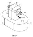
- FIG. 21illustrates a tissue head including a plurality of waveguide antennas according to one embodiment of the invention.
- FIG. 22illustrates a tissue head including a plurality of waveguide antennas according to one embodiment of the invention.
- FIG. 23illustrates a tissue head including a plurality of waveguide antennas according to one embodiment of the invention.
- FIG. 24illustrates a disposable tissue head for use with an applicator according to one embodiment of the invention.
- FIG. 25illustrates a disposable tissue head for use with an applicator according to one embodiment of the invention.
- FIG. 26illustrates a tissue profile according to one embodiment of the invention.
- FIG. 27illustrates a tissue profile according to one embodiment of the invention.
- FIG. 28illustrates a tissue profile according to one embodiment of the invention.
- FIG. 29illustrates a tissue profile according to one embodiment of the invention.
- FIG. 30illustrates a tissue profile according to one embodiment of the invention.
- FIG. 31illustrates a tissue profile according to one embodiment of the invention.
- FIG. 32illustrates a tissue profile according to one embodiment of the invention.
- FIG. 33illustrates a tissue profile according to one embodiment of the invention.
- FIG. 34illustrates a tissue profile according to one embodiment of the invention.
- FIG. 35illustrates a tissue profile according to one embodiment of the invention.
- FIG. 36illustrates a tissue profile according to one embodiment of the invention.
- FIG. 37illustrates a tissue profile according to one embodiment of the invention.
- FIG. 38illustrates a tissue profile according to one embodiment of the invention.
- FIG. 39illustrates a tissue profile according to one embodiment of the invention.
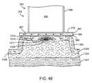
- FIG. 40illustrates a tissue profile according to one embodiment of the invention.
- FIG. 41illustrates a tissue profile according to one embodiment of the invention.
- FIG. 42illustrates a tissue profile according to one embodiment of the invention.
- FIG. 43illustrates a tissue profile according to one embodiment of the invention.
- FIG. 44illustrates a tissue profile according to one embodiment of the invention.
- FIG. 45illustrates a tissue profile according to one embodiment of the invention.
- FIG. 46illustrates a tissue profile according to one embodiment of the invention.
- FIG. 47illustrates a tissue profile according to one embodiment of the invention.
- FIG. 48illustrates a tissue profile according to one embodiment of the invention.
- FIG. 49illustrates a tissue profile according to one embodiment of the invention.
- FIG. 50illustrates a tissue profile according to one embodiment of the invention.
- FIG. 51illustrates a tissue profile according to one embodiment of the invention.
- each layer of tissueWhen skin is irradiated with electromagnetic radiation, such as, for example, microwave energy, energy is absorbed by each layer of tissue as the electromagnetic radiation passes through the tissue.
- the amount of energy absorbed by each tissue layeris a function of a number of variables.
- Some of the variables which control the amount of energy absorbed in each tissue layerinclude: the power of the electromagnetic radiation which reaches each layer; the amount of time each layer is irradiated; the electrical conductivity or loss tangent of the tissue in each layer and the radiation pattern of the antenna radiating the electromagnetic energy.
- the power which reaches a particular layer of tissueis a function of a number of variables.
- Some of the variables which control the power reaching a particular layer of tissueinclude the power impinging upon the surface of the skin and the frequency of the electromagnetic radiation. For example, at higher frequencies the penetration depth of the electromagnetic signal is shallow and most power is deposited in the upper layers of tissue, at lower frequencies, larger penetration depths result in power deposition in both upper and lower tissue layers.
- Heatmay be generated in tissue by a number of mechanisms. Some of the mechanisms for generating heat in tissue include resistive heating, dielectric heating and thermal conduction. Resistive heating occurs when electrical currents are generated in the tissue, resulting in resistive losses. Tissue may be resistively heated using, for example, mono-polar or bi-polar RF energy. Dielectric heating occurs when electromagnetic energy induces an increased physical rotation of polar molecules that converts microwave energy into heat. Tissue may be dielectrically heated by, for example, irradiating the tissue with electromagnetic energy in the microwave frequency band. As used herein, microwave frequency band or microwave frequencies may refer to, for example, electromagnetic energy at frequencies which are suitable for inducing dielectric heating in tissue when that tissue is irradiated using an external antenna to transmit the electromagnetic radiation.
- Such frequenciesmay be in the range of, for example, from approximately 100 Megahertz (MHz) to 30 Gigahertz (GHz).
- MHzMegahertz
- GHzGigahertz
- heat generated in one region of tissuemay be transmitted to adjacent tissue by, for example, thermal conduction, thermal radiation or thermal convection.
- a microwave signalWhen a microwave signal is radiated into a lossy dielectric material such as water, the energy of the signal is absorbed and converted to heat as it penetrates the material. This heat is primarily generated by induced physical rotation of molecules when subjected to the microwave signal.
- the efficiency of the conversion of microwave energy into heat for a given materialcan be quantified by the energy dissipation factor, or loss-tangent (tan ⁇ ).
- the loss-tangentvaries as a function of material composition and the frequency of the microwave signal.
- Waterhas a large loss-tangent and heats efficiently when irradiated with microwave energy. Since all biological tissue has some water content, and thus is lossy, it can be heated using microwave energy. Different tissue types have varying amounts of water content, with muscle and skin having a relatively high water content and fat and bone having significantly less water content. Microwave heating is generally more efficient in high water content tissues.
- the application of RF energy, which is conducted through the surface of the skin, or microwave energy, which is radiated through the surface of the skin, to heat tissue below the skin surfacegenerally results in a temperature gradient having a peak at the surface of the skin and decreasing with increasing depth into the tissue. That is, the hottest point is generally found at or near the surface of the skin.
- the temperature gradientresults from the power lost by the electromagnetic radiation as it moves through the tissue.
- the power loss density profilegenerally peaks in tissue at the skin surface and declines as the electromagnetic radiation moves through the tissue, regardless of the radiated power or frequency of the electromagnetic radiation. Power loss density is measured in watts per cubic meter.
- An equivalent characterization of power deposition in tissueis the Specific Absorption Rate (SAR) which is measured in watts per kilogram.
- SARSpecific Absorption Rate
- Specific absorption rate in tissuemay be, for example, proportional to the square of the magnitude of electric field in that tissue. For a fixed radiated power level the penetration depth will generally decrease as the frequency increases.
- tissue near the skin surfacesuch as, for example, the epidermis
- to heat tissue deep within the skin, such as, for example, in the deep dermis or the hypodermis, or below the skin surface, such as, for example, in muscle tissueone would generally select a lower frequency to ensure that sufficient energy reached the deeper tissue.
- Temperature gradients within tissuemay be modified to move the peak temperature into tissue below the skin surface by, for example, using external mechanisms to remove heat from tissue close to the skin surface.
- External mechanisms which remove heat from the surface of the skinmay include, for example, heat sinks which cool the skin surface and adjacent layers.
- FIG. 1is an illustration of human tissue structure.
- muscle tissue 1301is connected to hypodermis 1303 by connective tissue 1302 .
- Hypodermis 1303is connected to dermis 1305 at interface 1308 .
- Epidermis 1304lies over dermis 1305 .
- Skin surface 1306lies over epidermis 1304 and includes squamous epithelial cells 1345 and sweat pores 1347 .
- Tissue structures 1325such as, for example, sweat glands 1341 , sebaceous glands 1342 and hair follicles 1344 , may be positioned throughout dermis 1305 and hypodermis 1303 . Further, tissue structures 1325 may be positioned such that they cross or interrupt interface 1308 .
- Tissue structuressuch as, for example, apocrine glands, eccrine glands or hair follicles may be expected to have sizes in the range of, for example, between approximately 0.1 millimeter and two millimeters and may group together to form groups or structures having even larger sizes.
- interface 1308may be expected to be a non-linear, non-continuous, rough interface which may also include many tissue structures and groups of tissue structures which cross and interrupt interface 1308 .
- dielectric constantsand/or conductivity characteristics of the tissue layers because of the variability from person to person and within body regions of individuals.
- tissue structures and of groups of tissue structurescreate additional complexities. Assuming an average dielectric constant for a particular layer does not generally reflect the complexity of the actual tissue, however, it may be used as a starting point. For example, assuming a dielectric constant of, for example, approximately 66 for dermal tissue at 100 MHz, electromagnetic energy at the low end of the microwave range, would have a wavelength of approximately 370 millimeters. Assuming a dielectric constant of, for example, approximately 38 for dermal tissue at 6.0 GHz, electromagnetic energy would have a wavelength of approximately 8 millimeters in dermal tissue.
- the electromagnetic energyWhen electromagnetic energy is transmitted through a medium having structures and interfaces, including interfaces between tissue layers, the electromagnetic energy will, depending upon the electrical and physical characteristics of the structures, groups of structures and interfaces, and the differences between electrical and physical characteristics of such structures, groups of structures and interfaces and surrounding tissue, be scattered and/or reflected by the structures, groups of structures and/or interfaces.
- reflected electromagnetic wavesinteract with incident electromagnetic waves they may, under certain circumstances, combine to form a standing wave having one or more constructive interference peaks, such as, for example an E-field peak, and one or more interference minimums (also referred to as regions of destructive interference). However, scattering will tend to minimize or destroy such constructive interference peaks.
- dermal tissuemay be modeled to include a dermis and an epidermis.
- dermal tissuemay be modeled to have a conductivity of approximately 4.5 siemens per meter at approximately 6 GHz.
- dermal tissuemay be modeled to have a dielectric constant of approximately 40 at approximately 6 GHz.
- hypodermal tissuemay be modeled to have a conductivity of approximately 0.3 siemens per meter at approximately 6 GHz.
- hypodermal tissuemay be modeled to have a dielectric constant of approximately 5 at approximately 6 GHz.
- FIGS. 2 through 25 and 48 through 51illustrate embodiments and components of embodiments of systems according to the invention which may be used to generate heat in selected tissue regions.
- FIGS. 2 through 25 and 48 through 51illustrate embodiments and components of embodiments of systems according to the invention which may be used to generate predetermined specific absorption rate profiles in selected tissue regions.
- FIGS. 2 through 25 and 48 through 51illustrate embodiments and components of embodiments of systems according to the invention which may be used to generate predetermined specific absorption rate profiles such as, for example, the specific absorption rate profiles illustrated in FIGS. 26 through 51 .
- FIGS. 2 through 25 and 48 through 51illustrate embodiments and components of embodiments of systems according to the invention which may be used to generate predetermined specific absorption rate or power loss density profiles in selected tissue regions.
- FIGS. 2 through 25 and 48 through 51illustrate embodiments and components of embodiments of systems according to the invention which may be used to generate predetermined power loss density profiles such as, for example, the power loss density profiles illustrated in FIGS. 26 through 51 .
- FIGS. 2 through 25 and 48 through 51illustrate embodiments and components of embodiments of systems according to the invention which may be used to generate predetermined temperature profiles in selected tissue regions.
- FIGS. 2 through 25 and 48 through 51illustrate embodiments and components of embodiments of systems according to the invention which may be used to generate predetermined temperature profiles such as, for example, the temperature profiles illustrated in FIGS. 26 through 51 .
- FIGS. 2 through 25 and 48 through 51illustrate embodiments and components of embodiments of systems according to the invention which may be used to create lesions in selected tissue regions.
- FIGS. 2 through 25 and 48 through 51illustrate embodiments and components of embodiments of systems according to the invention which may be used to create lesions in selected regions by generating specific absorption rate profiles with a peak in the selected tissue regions.
- FIGS. 2 through 25 and 48 through 51illustrate embodiments and components of embodiments of systems according to the invention which may be used to create lesions in selected tissue by generating specific absorption rate profiles such as, for example, the specific absorption rate profiles illustrated in FIGS. 26 through 51 , wherein the lesion is created in region of the tissue corresponding to the peak specific absorption rate.
- FIGS. 2 through 25 and 48 through 51illustrate embodiments and components of embodiments of systems according to the invention which may be used to create lesions in selected regions by generating power loss density profiles with a peak in the selected tissue regions.
- FIGS. 2 through 25 and 48 through 51illustrate embodiments and components of embodiments of systems according to the invention which may be used to create lesions in selected tissue by generating power loss density profiles such as, for example, the power loss density profiles illustrated in FIGS. 26 through 51 , wherein the lesion is created in region of the tissue corresponding to the peak power loss density.
- FIGS. 2 through 25 and 48 through 51illustrate embodiments and components of embodiments of systems according to the invention which may be used to create lesions in selected regions by generating temperature profiles with a peak in the selected tissue regions.
- FIGS. 2 through 25 and 48 through 51illustrate embodiments and components of embodiments of systems according to the invention which may be used to create lesions in selected tissue by generating temperature profiles such as, for example, the temperature profiles illustrated in FIGS. 26 through 51 wherein the lesion is created in region of the tissue corresponding to the peak temperature.
- FIGS. 3-7C and pp. 8-13of U.S. Provisional App. No. 60/912,899; and FIGS. 3-9 and 20-26 and pp. 34-48 and FIGS. 20-26 of U.S. Provisional App. No.
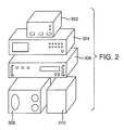
- FIG. 2illustrates one embodiment of a system for generating and controlling microwave energy according to one embodiment of the invention.
- controller 302may be, for example, a custom digital logic timer controller module that controls the delivery of microwave energy generated by signal generator 304 and amplified by amplifier 306 . Controller 302 may also control a solenoid valve to control application of vacuum from the vacuum source 308 .
- signal generator 304may be, for example, a Model N5181A MXG Analog Signal Generator 100 KHz-6 GHz, available from Agilent Technologies.
- amplifier 306may be, for example, a Model HD18288SP High Power TWT Amplifier 5.7-18 GHz, available from HD Communications Corporation.
- vacuum source 308may be, for example, a Model 0371224 Basic 30 Portable Vacuum Pump, available from Medela.
- coolant source 310may be, for example, a 0P9TNAN001 NanoTherm Industrial Recirculating Chiller available from ThermoTek, Inc.
- FIG. 3illustrates a system for delivering microwave energy according to one embodiment of the invention.
- poweris supplied by power source 318 , which may be, for example an AC mains power line.
- isolation transformer 316isolates the mains power provided by power source 318 and supplies isolated power to controller 302 , vacuum source 308 , signal generator 304 , amplifier 306 , temperature data acquisition system 314 and coolant source 310 .
- vacuum cable 372connects vacuum source 308 to applicator 320 .
- FIG. 3illustrates a system for delivering microwave energy according to one embodiment of the invention.
- signal generator 304generates a signal, which may be, for example, a continuous wave (CW) signal having a frequency in the range of, for example, 5.8 GHz and that signal is supplied to amplifier 306 , which is controlled by controller 302 .
- CWcontinuous wave
- an output signal from amplifier 306may be transmitted to an applicator 320 by signal cable 322 .
- signal cable 322may be, for example, a fiber optic link.
- applicator 320may be, for example, a microwave energy device.
- coolant source 310may supply a coolant, such as, for example, chilled de-ionized water, to applicator 320 through coolant tubing 324 , and, more particularly, coolant may be supplied to applicator 320 through inflow tubing 326 and returned to coolant source 310 through outflow tubing 328 .
- applicator 320includes temperature measurement devices which relay temperature signals 330 to the temperature data acquisition system 314 , which, in turn, relays temperature signals by a fiber optic link 332 to the temperature display computer 312 .
- isolation transformer 316may be ISB-100W Isobox, available from Toroid Corporation of Maryland.
- temperature display computer 312may be, for example, a custom timer controller developed from a number of off-the-shelf timer relay components and custom control circuitry.
- temperature data acquisition system 314may be, for example, a Thermes-USB Temperature Data Acquisition System with OPT-1 Optical Link available from Physitemp Instruments Inc.
- FIG. 4is a side perspective view of a microwave applicator according to one embodiment of the invention.
- FIG. 5is a top perspective view of a microwave applicator according to one embodiment of the invention.
- FIG. 6is a front view of a microwave applicator according to one embodiment of the invention.
- applicator 320includes applicator cable 334 , applicator handle 344 , applicator head 346 and tissue head 362 .
- tissue head 362includes vacuum ports 342 , cooling plate 340 , tissue chamber 338 and tissue interface 336 .
- tissue head 362may be referred to as a tissue acquisition head.
- tissue head 362includes alignment guide 348 , which includes alignment features 352 .
- tissue head 362is mounted on applicator head 346 of applicator 320 .
- tissue head 362includes alignment guide 348 , alignment features 352 and tissue chamber 338 .
- tissue chamber 338includes tissue wall 354 and tissue interface 336 .
- tissue interface 336includes cooling plate 340 , vacuum ports 342 and vacuum channel 350 .
- FIG. 7is a front view of a tissue head for use with a microwave applicator according to one embodiment of the invention.
- tissue head 362includes alignment guide 348 , alignment features 352 and tissue chamber 338 .
- tissue chamber 338includes tissue wall 354 and tissue interface 336 .
- tissue interface 336includes cooling plate 340 , vacuum ports 342 and vacuum channel 350 .
- tissue head 362is detachable and may be used as a disposable element of a microwave applicator such as, for example, applicator 320 .
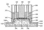
- FIG. 8is a cut away view of a tissue head according to one embodiment of the invention.
- FIG. 8is a cutaway view of a tissue head 362 and antenna 358 according to one embodiment of the invention.
- antenna 358may be, for example, a waveguide 364 which may include, for example, waveguide tubing 366 and dielectric filler 368 .
- antenna 358is isolated from cooling fluid 361 in coolant chamber 360 by standoff 376 .
- chamber wall 354has a chamber angle Z which facilitates the acquisition of tissue.
- tissue interface 336which may include cooling plate 340 , has a minimum dimension X and tissue chamber 338 has a depth Y.
- FIG. 9is a side cutaway view of a microwave applicator according to one embodiment of the invention.
- FIG. 10is a top perspective partial cutaway view of a microwave applicator according to one embodiment of the invention.
- FIG. 11is a side partial cutaway view of a microwave applicator according to one embodiment of the invention.
- applicator 320includes applicator housing 356 and tissue head 362 .
- applicator housing 356encloses applicator handle 344 and at least a portion of applicator head 346 .
- FIGS. 9the embodiment of the invention illustrated in FIGS.
- applicator cable 334includes coolant tubing 324 , inflow tubing 326 , outflow tubing 328 , signal cable 322 and vacuum cable 372 .
- vacuum cable 372is connected to vacuum splitter 374 .
- applicator 320includes antenna 358 .
- antenna 358may include waveguide antenna 364 .
- waveguide antenna 364may include dielectric filler 368 and waveguide tubing 366 .
- cooling chamber 360may be configured to facilitate the continuous flow of cooling fluid 361 across one surface of cooling plate 340 .
- signal cable 322is connected to antenna 358 by antenna feed 370 , which may be, for example a distal end of a semi-rigid coaxial cable or a panel mount connector and includes the center conductor of the cable or connector.
- applicator 320includes tissue head 362 .
- tissue head 362includes tissue chamber 338 , chamber wall 354 , cooling plate 340 and cooling chamber 360 .
- cooling chamber 360is connected to inflow tubing 326 and outflow tubing 328 .
- vacuum cable 372is connected to secondary vacuum cables 375 .
- secondary vacuum cables 375may be connected to vacuum ports 342 (not shown) in tissue head 362 .
- vacuum cable 372is connected to secondary vacuum cables 375 .
- secondary vacuum cables 375may be connected to vacuum ports 342 (not shown) in tissue head 362 .
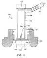
- FIGS. 12 and 13are cutaway views of a tissue head and antenna according to one embodiment of the invention.
- FIGS. 14 through 18are cutaway views of a tissue head, antenna and field spreader according to one embodiment of the invention.
- FIG. 19is a cutaway view of a tissue head, antenna and field spreader with tissue engaged according to one embodiment of the invention.
- antenna 358may be, for example, a waveguide antenna 364 .
- waveguide antenna 364may comprise, for example, waveguide tubing 366 and waveguide filler 368 and may be connected to signal cable 322 by, for example, antenna feed 370 .
- tissue head 362may comprise, for example, tissue chamber 338 , chamber wall 354 , cooling plate 340 and cooling chamber 360 .
- cooling chamber 360may include cooling fluid 361 .
- antenna 358is isolated from cooling fluid 361 in coolant chamber 360 by standoff 376 .
- at least a portion of antenna 358is positioned in coolant chamber 360 .
- at least a portion of waveguide antenna 364is positioned in coolant chamber 360 .
- waveguide antenna 364is positioned in coolant chamber 360 such that at least a portion of waveguide tubing 366 and dielectric filler 368 contact cooling fluid 361 in coolant chamber 360 .
- field spreader 378is positioned at an output of waveguide antenna 364 . In one embodiment of the invention illustrated in FIG. 14 field spreader 378 is an extension of dielectric filler 368 and is positioned at an output of waveguide antenna 364 . In one embodiment of the invention illustrated in FIG. 14 field spreader 378 is an extension of dielectric filler 368 extending into coolant chamber 360 . In one embodiment of the invention illustrated in FIG. 14 field spreader 378 is an extension of dielectric filler 368 extending through coolant chamber 360 to cooling plate 340 .
- field spreader 380is integrated into dielectric filler 368 of waveguide antenna 364 .
- field spreader 380is a region of dielectric filler 368 having a dielectric constant which differs from the dielectric constant of the remainder of dielectric filler 368 .
- region having a dielectric constantwhich is in the range of approximately 1 to 15.
- field spreader 382is integrated into dielectric filler 368 of waveguide antenna 364 and extends into coolant chamber 360 . In one embodiment of the invention illustrated in FIG. 16 field spreader 382 is integrated into dielectric filler 368 of waveguide antenna 364 and extends through coolant chamber 360 to cooling plate 340 . In one embodiment of the invention illustrated in FIG. 16 field spreader 382 has a dielectric constant which differs from the dielectric constant of dielectric filler 368 . In one embodiment of the invention illustrated in FIG. 15 field spreader 380 is a region having a dielectric constant which is in the range of approximately 1 to 15. In one embodiment of the invention illustrated in FIG.
- a field spreadermay be comprised of a notch 384 in dielectric filler 368 .
- notch 384is a cone shaped notch in dielectric filler 368 .
- notch 384is connected to cooling chamber 360 such that cooling fluid 361 in cooling chamber 360 at least partially fills notch 384 .
- notch 384is connected to cooling chamber 360 such that cooling fluid 361 in cooling chamber 360 fills notch 384 .
- field spreader 382is integrated into or protrudes from cooling plate 340 . In one embodiment of the invention illustrated in FIG. 18 field spreader 382 is integrated into or protrudes from cooling plate 340 at tissue interface 336 . In one embodiment of the invention illustrated in FIG. 18 field spreader 382 is integrated into or protrudes from cooling plate 340 into tissue chamber 338 . In one embodiment of the invention illustrated in FIG. 18 field spreader 382 may form at least a portion of tissue interface 336 .
- skin 1307is engaged in tissue chamber 338 .
- dermis 1305 and hypodermis 1303are engaged in tissue chamber 338 .
- skin surface 1306is engaged in tissue chamber 338 such that skin surface 1306 is in contact with at least a portion of chamber wall 354 and cooling plate 340 .
- skin surface 1306is engaged in tissue chamber 338 such that skin surface 1306 is in contact with at least a portion of tissue interface 336 .
- a vacuum pressuremay be used to elevate dermis 1305 and hypodermis 1303 , separating dermis 1305 and hypodermis 1303 from muscle 1301 .
- a vacuum pressuremay be used to elevate dermis 1305 and hypodermis 1303 , separating dermis 1305 and hypodermis 1303 from muscle 1301 to, for example, protect muscle 1301 by limiting or eliminating the electromagnetic energy which reaches muscle 1301 .
- FIG. 20is a cutaway view of a tissue head and antenna with tissue engaged according to one embodiment of the invention.
- applicator 320includes applicator housing 356 , antenna 358 , vacuum channels 350 and tissue head 362 .
- tissue head 362includes vacuum conduit 373 , cooling elements 386 and cooling plate 340 .
- cooling elements 386may be, for example: solid coolants; heat sinks; liquid spray, gaseous spray, cooling plates, thermo-electric coolers; or and combinations thereof.
- vacuum channels 350are connected to vacuum conduit 373 and vacuum port 342 .
- skin surface 1306is engaged in tissue chamber 338 by, for example a vacuum pressure at vacuum ports 342 , such that skin surface 1306 is in contact with at least a portion of chamber wall 354 and cooling plate 340 .
- skin surface 1306is engaged in tissue chamber 338 by, for example a vacuum pressure at vacuum ports 342 , such that skin surface 1306 is in contact with at least a portion of tissue interface 336 .
- a vacuum pressure at vacuum ports 342may be used to elevate dermis 1305 and hypodermis 1303 , separating dermis 1305 and hypodermis 1303 from muscle 1301 .
- FIG. 20As illustrated in FIG.
- a vacuum pressure at vacuum ports 342may be used to elevate dermis 1305 and hypodermis 1303 , separating dermis 1305 and hypodermis 1303 from muscle 1301 to, for example, protect muscle 1301 by limiting or eliminating the electromagnetic energy which reaches muscle 1301 .
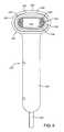
- FIGS. 21 through 23illustrate tissue heads including a plurality of waveguide antennas according to one embodiment of the invention.
- a tissue head 362includes a plurality of waveguide antennas 364 according to embodiments of the invention.
- two waveguide antennas 364are positioned in tissue head 362 .
- four waveguide antennas 364are positioned in tissue head 362 .
- six waveguide antennas 364are positioned in tissue head 362 .
- waveguides 364include feed connectors 388 and tuning screws 390 .
- FIG. 24illustrates a disposable tissue head 363 for use with an applicator 320 according to one embodiment of the invention.
- disposable tissue head 363may have all of the elements of tissue head 362 .
- disposable tissue head 363may include elements of tissue head 362 , such as, for example, tissue interface 336 , cooling plate 340 , tissue chamber 338 , or vacuum ports 342 .
- disposable tissue head 363may include a cooling chamber 360 .
- disposable tissue head 363may include a standoff 376 .
- disposable tissue head 363engages with applicator housing 356 , positioning antennas 364 in disposable tissue head 363 .
- FIG. 24disposable tissue head 363 engages with applicator housing 356 , positioning antennas 364 in disposable tissue head 363 .
- FIG. 25illustrates a disposable tissue head 363 for use with an applicator 320 according to one embodiment of the invention.
- disposable tissue head 363engages with applicator housing 356 and is held in place with latches 365 .
- FIGS. 26 through 51illustrate a series of profiles, including, for example, profiles of power deposition, profiles of power loss density, profiles of specific absorption rates or profiles of tissue temperature, according to embodiments of the invention.
- profilessuch as for example, profiles of power deposition, profiles of power loss density, profiles of specific absorption rates or profiles of tissue temperature may be referred to as tissue profiles.
- the illustrated tissue profilesmay be representative of, for example, SAR profiles, power loss density profiles or temperature profiles.
- FIGS. 3A-7C and pp. 16-20 of Appendix 1 and FIGS. 20-26 and pp. 38-46 of Appendix 2may be used to generate the tissue profiles illustrated in FIGS. 26 through 51 .
- FIGS. 26 through 35illustrate a series of tissue profiles according to embodiments of the invention.
- antenna 358may be, for example, a simple dipole antenna or a waveguide antenna.
- antenna 358may be positioned in a medium 1318 .
- antenna 358radiates an electromagnetic signal through medium 1318 and into tissue, generating the patterns illustrated in FIGS. 26 through 35 .
- medium 1318may be, for example, a dielectric material having a dielectric constant (which may also be referred to as permittivity) of approximately 10.
- antenna 358may radiate energy at a frequency of, for example, approximately 3.0 GHz.
- antenna 358may radiate energy at a frequency of, for example, approximately 3.5 GHz.
- antenna 358may radiate energy at a frequency of, for example, approximately 4.0 GHz.
- antenna 358may radiate energy at a frequency of, for example, approximately 4.5 GHz.
- antenna 358may radiate energy at a frequency of, for example, approximately 5.0 GHz.
- antenna 358may radiate energy at a frequency of, for example, approximately 5.8 GHz.
- antenna 358may radiate energy at a frequency of, for example, approximately 6.5 GHz.
- antenna 358may radiate energy at a frequency of, for example, approximately 7.5 GHz.
- antenna 358may radiate energy at a frequency of, for example, approximately 8.5 GHz.
- antenna 358may radiate energy at a frequency of, for example, approximately 9.0 GHz.
- a tissue profilesuch as the profile illustrated in FIGS.
- a tissue profilesuch as the profile illustrated in FIGS. 34 and 35 may include at least two constructive interference peaks, where in a second constructive interference peak is positioned near a skin surface.
- antenna 358is representative of a wave guide antenna such as, for example, the waveguide antenna illustrated in FIG. 48 radiating through, for example, at least a portion of a tissue head including a tissue interface
- the frequencies at which particular tissue profiles, such as, for example, SAR profiles, power loss profiles or temperature profiles are createdmay vary from the frequencies at which that such profiles are generated by a dipole antenna.
- a tissue head positioned between a waveguide antenna and a skin surfacemay comprise, for example, for example, a standoff 376 , a cooling chamber 360 filled with cooling fluid 361 , such as, for example de-ionized water and a cooling plate 340 .
- antenna 358may be positioned a distance of approximately 1.5 millimeters from skin surface 1306 .
- FIG. 34illustrates a resulting profile where antenna 358 is a waveguide antenna radiating energy through a tissue head at a frequency of, for example, approximately 10 GHz.
- FIG. 35illustrates a resulting profile where antenna 358 is a waveguide antenna radiating energy through a tissue head at a frequency of, for example, approximately 12 GHz.
- antenna 358may be a dipole antenna and may have a length of, for example, approximately one half wavelength (measured at the operational frequency). In embodiments of the invention illustrated in FIGS. 26 through 35 , antenna 358 may be positioned in, for example, a radiating near field region with respect to skin surface 1306 . In embodiments of the invention illustrated in FIGS. 26 through 35 antenna 358 may be positioned at a distance of, for example, approximately 10 millimeters from skin surface 1306 . In embodiments of the invention illustrated in FIGS. 26 through 30 antenna 358 may be a dipole antenna having an antenna height of, for example, approximately 12 millimeters. In one embodiment of the invention illustrated in FIG.
- antenna 358may be a dipole antenna having an antenna height of, for example, approximately 8.5 millimeters. In embodiments of the invention illustrated in FIGS. 32 through 35 antenna 358 may be a dipole antenna having an antenna height of, for example, approximately 7 millimeters.
- power from antenna 358is transmitted through skin surface 1306 , generating a profile, such as, for example, a SAR profile, a power loss density profile or a temperature profile, in, for example, dermis 1305 .
- a profilesuch as, for example, a SAR profile, a power loss density profile or a temperature profile, in, for example, dermis 1305 .
- power transmitted from antenna 358 though skin surface 1306generates a profile having a peak in first tissue region 1309 .
- power transmitted from antenna 358 though skin surface 1306generates a profile wherein the magnitude decreases from first tissue region 1309 to second tissue region 1311 .
- FIGS. 26 through 35power transmitted from antenna 358 though skin surface 1306 generates a profile wherein the magnitude decreases from second tissue region 1311 to third tissue region 1313 .
- power transmitted from antenna 358 though skin surface 1306generates a profile wherein the magnitude decreases from third tissue region 1313 to fourth tissue region 1315 .
- interface 1308may be idealized as a substantially straight line for the purpose of simplified illustration, however, in actual tissue, interface 1308 may be expected to be a non-linear, non continuous, rough interface which may also include tissue structures and groups of tissue structures which cross and interrupt interface 1308 .
- a peak magnitude of, for example, SAR, power loss density or temperatureis formed as a result of constructive interference between incident and reflected power.
- a peak magnitude of, for example, SAR, power loss density or temperature formed as a result of constructive interference between incident and reflected poweris positioned at first tissue region 1309 below a first layer of dermal tissue.
- a minimum magnitude of, for example, SAR, power loss density or temperatureis formed as a result of destructive interference between incident and reflected power.
- a minimum magnitude of, for example, SAR, power loss density or temperature formed as a result of destructive interference between incident and reflected poweris positioned in a first layer of dermal tissue near skin surface 1306 .
- interface 1308may be, for example, an interface between dermis 1305 and hypodermis 1303 .
- first tissue region 1309may be formed in the lower half of the dermis.
- interface 1308may be, for example, an interface between a high dielectric, high conductivity tissue layer and a low dielectric, low conductivity tissue layer.
- interface 1308may be, for example, an interface between a high dielectric, high conductivity tissue layer and a low dielectric tissue layer
- interface 1308may be, for example, an interface between a glandular layer and a layer of the hypodermis.
- energy transmitted through skin surface 1306creates a peak temperature in first region 1309 .
- energy transmitted through skin surface 1306raises a temperature in first region 1309 to a temperature sufficient to induce hyperthermia in tissue in region 1309 .
- energy transmitted through skin surface 1306raises a temperature in first region 1309 to a temperature sufficient to ablate tissue in region 1309 .
- energy transmitted through skin surface 1306raises a temperature in first region 1309 to a temperature sufficient to cause cell death in tissue in region 1309 .
- energy transmitted through skin surface 1306raises a temperature in first region 1309 to a temperature sufficient to form a lesion core in first region 1309 . In one embodiment of the invention, energy transmitted through skin surface 1306 raises a temperature in first region 1309 to a temperature sufficient to create a lesion in tissue in region 1309 . In one embodiment of the invention, energy transmitted through skin surface 1306 raises the temperature of tissue in region 1309 by dielectric heating. In one embodiment of the invention, energy transmitted through skin surface 1306 preferentially raises the temperature of tissue in region 1309 above the temperature of surrounding regions. In one embodiment of the invention, energy transmitted through skin surface 1306 preferentially raises the temperature of tissue in region 1309 above the temperature of surrounding regions to a temperature sufficient to cause secondary effects, such as, for example the destruction of bacteria in such surrounding regions.
- energy transmitted through skin surface 1306generates a temperature in first region 1309 sufficient to heat tissue around first region 1309 , by, for example, thermal conductive heating.
- energy transmitted through skin surface 1306generates a temperature in first region 1309 sufficient to heat tissue structures, such as, for example, sweat glands or hair follicles, in tissue around first region 1309 , by, for example, thermal conductive heating.
- energy transmitted through skin surface 1306generates a temperature in first region 1309 sufficient to cause hyperthermia in tissue around first region 1309 , by, for example, thermal conductive heating.
- energy transmitted through skin surface 1306generates a temperature in first region 1309 sufficient to ablate tissue around first region 1309 , by, for example, thermal conductive heating. In one embodiment of the invention, energy transmitted through skin surface 1306 generates a temperature in first region 1309 sufficient to kill bacteria in tissue or tissue structures around first region 1309 , by, for example, thermal conductive heating. In one embodiment of the invention, energy transmitted through skin surface 1306 generates a temperature in first region 1309 sufficient to create a lesion in tissue around first region 1309 , by, for example, thermal conductive heating. In one embodiment of the invention, energy transmitted through skin surface 1306 generates a temperature in first region 1309 sufficient to expand a lesion into tissue around first region 1309 , by, for example, thermal conductive heating.
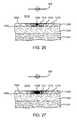
- FIGS. 36 through 39illustrate a series of tissue profiles according to one embodiment of the invention.
- antenna 358may be, for example, a simple dipole antenna or a waveguide antenna.
- antenna 358may be excited at a predetermined frequencies such as, for example, approximately 5.8 GHz.
- antenna 358may be positioned in, for example, a radiating near field region with respect to skin surface 1306 .
- antenna 358may be positioned in, for example, a reactive near field region with respect to skin surface 1306 .
- antenna 358may be positioned at a distance A of, for example, between approximately 10 millimeters and approximately 2 millimeters from skin surface 1306 . In embodiments of the invention illustrated in FIGS. 36 through 39 antenna 358 may be positioned in a medium 1318 . In embodiments of the invention illustrated in FIGS. 36 through 39 antenna 358 may be a dipole antenna having an antenna height of approximately 8.5 millimeters. In the embodiments of the invention illustrated in FIGS. 36 through 39 antenna 358 may radiate energy at a frequency of, for example, approximately 5.8 GHz.
- power from antenna 358is transmitted through skin surface 1306 , generating a tissue profile in dermis 1305 .
- power transmitted from antenna 358 though skin surface 1306generates a tissue profile having a peak in first tissue region 1309 .
- power transmitted from antenna 358 though skin surface 1306generates a tissue profile which may represent, for example, SAR, power loss density or temperature.
- tissue profilewherein the magnitude of, for example, SAR, power loss density or temperature, decreases from first tissue region 1309 to second tissue region 1311 , from second tissue region 1311 to third tissue region 1313 and from third tissue region 1313 to fourth tissue region 1315 .
- power transmitted from antenna 358 through skin surface 1306is at least partially reflected off of interface 1308 such that a peak of, for example, SAR, power loss density or temperature, is generated in first tissue region 1309 below skin surface 1306 .
- a peak of, for example, SAR, power loss density or temperature formed as a result of constructive interference between incident and reflected poweris positioned at first tissue region 1309 below a first layer of dermal tissue.
- a peak of, for example, SAR, power loss density or temperature formed as a result of constructive interference between incident and reflected poweris positioned at first tissue region 1309 in a lower half of dermis 1305 .
- antenna 358may be positioned at a distance A of, for example, approximately 10 millimeters from skin surface 1306 .
- antenna 358may be positioned at a distance A of, for example, approximately 5 millimeters from skin surface 1306 .
- antenna 358may be positioned at a distance A of, for example, approximately 3 millimeters from skin surface 1306 .
- FIG. 36a peak of, for example, SAR, power loss density or temperature formed as a result of constructive interference between incident and reflected power is positioned at first tissue region 1309 in a lower half of dermis 1305 .
- antenna 358may be positioned at a distance A of, for example, approximately 10 millimeters from skin surface 1306 .
- antenna 358may be positioned at a distance A of, for
- antenna 358may be positioned at a distance A of, for example, approximately 2 millimeters from skin surface 1306 .
- tissue in region 1309is preferentially heated with respect to tissue in layers above first tissue region 1309 .
- antenna 358may be positioned at a distance A within a radiating near field of skin surface 1306 .
- antenna 358may be positioned at a distance A within a radiating near field of skin surface 1306 .
- antenna 358may be positioned at a distance A within a radiating near field of skin surface 1306 .
- antenna 358may be positioned at a distance A within a reactive near field of skin surface 1306 . As illustrated in FIG.
- a reactive near fieldmay be that distance which results in substantial reactive coupling between an antenna and adjacent tissue, increasing power deposition at the upper skin layer and destroying the preferential heating profiles illustrated in FIGS. 36 thorough 38
- FIGS. 40 through 43illustrate tissue profiles according to one embodiment of the invention.
- dermis 1305 and hypodermis 1303may contain tissue structures 1325 which may be, for example, sweat glands, including, for example, eccrine glands, apocrine glands or apoeccrine glands.
- dermis 1305 and hypodermis 1303may contain tissue structures 1325 which may be, for example, sweat glands, including, for example, eccrine glands, apocrine glands or apoeccrine glands.
- FIGS. 40 through 43illustrate tissue profiles according to one embodiment of the invention.
- dermis 1305 and hypodermis 1303may contain tissue structures 1325 which may be, for example, sweat glands, including, for example, eccrine glands, apocrine glands or apoeccrine glands.
- tissue structures 1325may be, for example, hair follicles.
- tissue structures 1325may include ducts 1329 extending from tissue structures 1325 to skin surface 1306 .
- tissue structures 1325include groups of tissue structures 1325 .
- FIG. 40illustrates a tissue profile according to one embodiment of the invention.
- a lesion core 1321is created in a predetermined portion of dermis 1305 by, for example, irradiating dermis 1305 with electromagnetic radiation to generate dielectric heating in tissue at lesion core 1321 .
- lesion core 1321may be, for example, a point or region within a tissue layer where a lesion starts to grow.
- lesion core 1321is created by heat generated in dermal tissue by dielectric heating of lesion core 1321 .
- lesion core 1321expands as energy is added to dermis 1305 .
- lesion core 1321may be located in a region of dermis 1305 where a constructive interference peak is generated by electromagnetic energy transmitted through skin surface 1306 .
- lesion core 1321may be located in a region of dermis 1305 where a constructive interference peak is generated by electromagnetic energy transmitted through skin surface wherein at least a portion of the electromagnetic energy transmitted through skin surface 1306 reflects off of interface 1308 which may be, for example, an interface between high dielectric, high conductivity tissue and low dielectric, low conductivity tissue.
- 40 lesion core 1321may be located in a region of dermis 1305 where a constructive interference peak is generated by electromagnetic energy transmitted through skin surface 1306 wherein at least a portion of the electromagnetic energy transmitted through skin surface 1306 reflects off of interface 1308 which may be, for example, an interface between high dielectric, high conductivity tissue and low dielectric tissue.
- interface 1308may be, for example, an interface between high dielectric, high conductivity tissue and low dielectric tissue.
- interface 1308may be a non-linear, non continuous, rough interface which may also include many tissue structures and groups of tissue structures which cross and interrupt the tissue interface.
- 40 lesion core 1321may be located in a region of dermis 1305 where a constructive interference peak is generated by electromagnetic energy transmitted through skin surface wherein at least a portion of the electromagnetic energy transmitted through skin surface 1306 reflects off of interface 1308 which may be, for example, an interface between dermis 1305 and hypodermis 1303 .
- FIG. 41illustrates a tissue profile according to one embodiment of the invention.
- lesion core 1321expands as energy is added to dermis 1305 , generating heat which is conducted into surrounding tissue creating expanded lesion 1323 .
- heat conducted from lesion core 1321 into expanded lesion 1323damages tissue, including tissue structures 1325 outside lesion 1321 .
- heat conducted from lesion core 1321 into expanded lesion 1323crosses interface 1308 and damages tissue below interface 1308 , including tissue structures 1325 outside and below lesion core 1321 .
- FIG. 42illustrates a tissue profile according to one embodiment of the invention.
- a lesion core 1321is created in a predetermined portion of dermis 1305 by, for example, irradiating dermis 1305 with electromagnetic radiation to generate dielectric heating in tissue at lesion core 1321 .
- lesion core 1321expands as energy is added to dermis 1305 .
- heatis removed from skin surface 1306 .
- heatis removed from dermis 1305 through skin surface 1306 .
- FIG. 42illustrates a tissue profile according to one embodiment of the invention.
- heatis removed from dermis 1305 through skin surface 1306 by cooling skin surface 1306 .
- heat removed from dermis 1305 through skin surface 1306prevents lesion core 1321 and expanded lesion 1323 from growing in the direction of skin surface 1306 .
- removed from dermis 1305 through skin surface 1306prevents lesion core 1321 and expanded lesion 1323 from growing into cooled region 1327 .
- FIG. 43illustrates a tissue profile according to one embodiment of the invention.
- a lesion core 1321is created in a predetermined portion of dermis 1305 by, for example, irradiating dermis 1305 with electromagnetic radiation to generate dielectric heating in tissue at lesion core 1321 and expanded lesion 1323 is created by heat conducted from lesion core 1321 .
- lesion core 1321expands as energy is added to dermis 1305 and expanded lesion 1323 expands as heat is conducted from lesion core 1321 .
- heatis removed from skin surface 1306 .
- FIG. 43illustrates a tissue profile according to one embodiment of the invention.
- heatis removed from dermis 1305 through skin surface 1306 .
- heatis removed from dermis 1305 through skin surface 1306 by cooling skin surface 1306 .
- heat removed from dermis 1305 through skin surface 1306prevents lesion core 1321 and expanded lesion 1323 from growing in the direction of skin surface 1306 .
- removed from dermis 1305 through skin surface 1306prevents lesion core 1321 and expanded lesion 1323 from growing into cooled region 1327 .
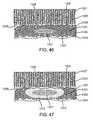
- FIGS. 44 through 47illustrate tissue profiles according to embodiments of the invention.
- dermis 1305 and hypodermis 1303may contain tissue structures 1325 which may be, for example, sweat glands, including, for example, eccrine glands, apocrine glands or apoeccrine glands.
- dermis 1305 and hypodermis 1303may contain tissue structures 1325 which may be, for example, sweat glands, including, for example, eccrine glands, apocrine glands or apoeccrine glands.
- FIGS. 44 through 47illustrate tissue profiles according to embodiments of the invention.
- dermis 1305 and hypodermis 1303may contain tissue structures 1325 which may be, for example, sweat glands, including, for example, eccrine glands, apocrine glands or apoeccrine glands.
- tissue structures 1325which may be, for example, hair follicles.
- tissue structures 1325may include ducts 1329 extending from tissue structures 1325 to skin surface 1306 .
- tissue structures 1325may be concentrated in a glandular layer 1331 .
- tissue structures 1325may be concentrated in a glandular layer 1331 wherein glandular layer 1331 has an upper interface 1335 and a lower interface 1333 .
- FIGS. 44 through 47tissue structures 1325 may be concentrated in a glandular layer 1331 wherein glandular layer 1331 has an upper interface 1335 and a lower interface 1333 .
- glandular layer 1331may have an upper interface 1335 between glandular layer 1331 and dermis 1305 .
- glandular layer 1331may have a lower interface 1333 between glandular layer 1331 and hypodermis 1303 .
- interface 1333may be, in actual tissue a non-linear, non continuous, rough interface which may also include many tissue structures and groups of tissue structures and groups of tissue structures which add to the roughness and nonlinearity of tissue interface 1333 .
- tissue structures 1325may be composed, at least in part of high dielectric/high conductivity tissue such as, for example, sweat glands.
- tissue structures 1325may be composed, at least in part of tissue having a high water content, such as, for example, sweat glands.
- tissue having a high water contentsuch as, for example, sweat glands.
- glandular layer 1331may be composed, at least in part of high dielectric/high conductivity tissue.
- FIGS. 44 through 47 glandular layer 1331may have an upper interface 1335 between glandular layer 1331 and high dielectric/high conductivity tissue, such as, for example, dermis 1305 .
- glandular layer 1331may have a lower interface 1333 between glandular layer 1331 and low dielectric/low conductivity tissue, such as, for example, hypodermis 1303 .
- glandular layer 1331may have a lower interface 1333 between glandular layer 1331 and low dielectric tissue.
- FIG. 44illustrates a tissue profile according to one embodiment of the invention.
- a lesion core 1321is created in a predetermined portion of glandular layer 1331 by, for example, irradiating glandular layer 1331 with electromagnetic radiation to generate dielectric heating in tissue at lesion core 1321 .
- lesion core 1321is created by heat generated in glandular layer 1331 by dielectric heating of lesion core 1321 .
- lesion core 1321expands as energy is added to glandular layer 1331 .
- FIG. 44illustrates a tissue profile according to one embodiment of the invention.
- 44 lesion core 1321may be located in a region of glandular layer 1331 where a constructive interference peak of, for example, SAR, power loss density or temperature, is generated by electromagnetic energy transmitted through skin surface 1306 .
- lesion core 1321may be located in a region of glandular layer 1331 where a constructive interference peak of, for example, SAR, power loss density or temperature, is generated by electromagnetic energy transmitted through skin surface 1306 wherein at least a portion of the electromagnetic energy transmitted through skin surface 1306 reflects off of lower interface 1333 .
- a constructive interference peak of, for example, SAR, power loss density or temperatureis generated by electromagnetic energy transmitted through skin surface 1306 wherein at least a portion of the electromagnetic energy transmitted through skin surface 1306 reflects off of lower interface 1333 .
- lesion core 1321may be located in a region of glandular layer 1331 where a constructive interference peak of, for example, SAR, power loss density or temperature, is generated by electromagnetic energy transmitted through skin surface 1306 wherein at least a portion of the electromagnetic energy transmitted through skin surface 1306 reflects off of lower interface 1333 which may be, for example, an interface between glandular layer 1331 and hypodermis 1303 .
- a constructive interference peak of, for example, SAR, power loss density or temperatureis generated by electromagnetic energy transmitted through skin surface 1306 wherein at least a portion of the electromagnetic energy transmitted through skin surface 1306 reflects off of lower interface 1333 which may be, for example, an interface between glandular layer 1331 and hypodermis 1303 .
- FIG. 45illustrates a tissue profile according to one embodiment of the invention.
- lesion core 1321expands as energy is added to glandular layer 1331 , generating heat which is conducted into surrounding tissue, creating expanded lesion 1323 .
- heat conducted from lesion core 1321 into expanded lesion 1323damages tissue, including tissue structures 1325 out side lesion core 1321 .
- heat conducted from lesion core 1321 into expanded lesion 1323crosses lower interface 1333 and damages tissue below lower interface 1333 and outside lesion core 1321 .
- FIGS. 46 and 47illustrate tissue profiles according to one embodiment of the invention.
- a lesion core 1321is created in a portion of glandular layer 1331 by, for example, irradiating glandular layer 1331 with electromagnetic radiation to generate dielectric heating in tissue at lesion core 1321 .
- lesion core 1321expands as energy is added to glandular layer 1331 and expanded lesion 1323 is created by heat conducted from lesion core 1323 .
- heatis removed from skin surface 1306 .
- heatis removed from dermal layer 1305 through skin surface 1306 .
- heatis removed from dermal layer 1305 through skin surface 1306 by cooling skin surface 1306 , creating cooled region 1307 in dermis 1305 .
- heat removed from dermal layer 1305 through skin surface 1306prevents expanded lesion 1323 from growing in the direction of skin surface 1306 .
- heat removed from glandular layer 1331 through skin surface 1306prevents expanded lesion 1323 from growing into cooled region 1327 .
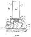
- FIGS. 48 through 51illustrate tissue profiles and apparatuses according to embodiments of the invention.
- antenna 358may be, for example, waveguide antenna 364 .
- waveguide antenna 364may include, for example, waveguide tubing 366 and dielectric filler 368 .
- electromagnetic energymay be radiated into dermis 1305 through a tissue head 362 which may include, for example, standoff 376 , coolant chamber 360 and cooling plate 340 .
- a peakwhich may be, for example, a peak SAR, peak power loss density or peak temperature, is generated in first tissue region 1309 .
- a reduced magnitudewhich may be, for example, a reduced SAR, reduced power loss density or reduced temperature, is generated in second tissue region 1311 with further reduced magnitudes in third tissue region 1313 and fourth tissue region 1315 .
- dermis 1305is separated from hypodermis 1303 by interface 1308 .
- interface 1308may be idealized as a substantially straight line for the purposes of simplified illustration, however, in actual tissue, interface 1308 may be a non-linear, non continuous, rough interface which may also include many tissue structures and groups of tissue structures which cross and interrupt the tissue interface.
- electromagnetic radiationmay be radiated at a frequency of, for example, between 5 and 6.5 GHz. In the embodiment of the invention illustrated in FIG. 48 electromagnetic radiation may be radiated at a frequency of, for example, approximately 5.8 GHz.
- dermis 1305may be assumed have a dielectric constant of, for example, approximately 38 and a conductivity of, for example, approximately 4.5 siemens per meter.
- hypodermis 1303may be assumed to have a dielectric constant of, for example, approximately 5 and a conductivity of, for example, approximately 0.31 siemens per meter.
- muscle tissue 1301may be assumed to have a dielectric constant of, for example, approximately 42 and a conductivity of, for example, approximately 5.2 siemens per meter.
- standoff 376may be, for example, polycarbonate and may have a dielectric constant of, for example, approximately 3.4 and a conductivity of, for example, approximately 0.0051 siemens per meter.
- cooling plate 340may be, for example, alumina (99.5%) and may have a dielectric constant of, for example, approximately 9.9 and a conductivity of, for example, approximately 3 ⁇ 10 ⁇ 4 siemens per meter.
- cooling fluid 361may be, for example, de-ionized water and may have, for example, a dielectric constant of, for example, approximately 81 and a conductivity of, for example, approximately 0.0001 siemens per meter.
- a peakwhich may be, for example, a peak SAR, peak power loss density or peak temperature
- a reduced magnitudewhich may be, for example, a reduced SAR, reduced power loss density or reduced temperature
- second tissue region 1311with further reduced magnitudes in third tissue region 1313 and fourth tissue region 1315 .
- dermis 1305is separated from hypodermis 1303 by interface 1308 .
- interface 1308may be modeled as a nonlinear interface, to more closely resemble an actual interface between dermal and hypodermal tissue.
- hypodermis 1303lies over muscle tissue 1301 .
- electromagnetic radiationmay be radiated at a frequency of, for example, 5.8 GHz.
- dermis 1305may be assumed to have a dielectric constant of, for example, 38.4 and a conductivity of, for example 4.54 siemens per meter.
- hypodermis 1303may be assumed to have, for example, a dielectric constant of, for example, 4.9 and a conductivity of, for example, 0.31 siemens per meter.
- 49 muscle tissue 1301may be assumed to have, for example, a dielectric constant of, for example, 42.22 and a conductivity of, for example, 5.2 siemens per meter.
- standoff 376may be, for example, polycarbonate and may have, for example, a dielectric constant of, for example, 3.4 and a conductivity of, for example, 0.0051 siemens per meter.
- cooling plate 340may be, for example, alumina (99.5%) and may have, for example, a dielectric constant of, for example, 9.9 and a conductivity of, for example, 3 ⁇ 10 ⁇ 4 siemens per meter.
- cooling fluid 361may be, for example, de-ionized water and may have, for example, a dielectric constant of, for example, 81 and a conductivity of, for example, 0.0001 siemens per meter.
- FIG. 50illustrates a tissue profile according to one embodiment of the invention.
- FIG. 51illustrates a tissue profile according to one embodiment of the invention.
- antenna 358may be, for example, a waveguide antenna 364 .
- waveguide antenna 364may have a dielectric filler 368 .
- antenna 358may be positioned on, for example, a tissue head 362 comprising, for example, standoff 376 , coolant chamber 360 and cooling plate 340 .
- cooling chamber 340may contain cooling fluid 361 , which may be, for example de-ionized water.
- a tissue head 362may include a tissue chamber (not shown) adapted to position tissue against tissue interface 336 .
- antenna 358is adapted to transmit electromagnetic radiation through skin surface 1306 creating a tissue profile which may be representative of, for example, a SAR profile, a power loss density profile or a temperature profile.
- the tissue profileincludes first tissue region 1309 , second tissue region 1311 , third tissue region 1313 and fourth tissue region 1315 .
- first tissue region 1309may represent, for example, a peak SAR, peak power loss density or peak temperature.
- first tissue region 1309may be located in, for example, dermis 1305 , near an interface 1308 between dermis 1305 and hypodermis 1303 , which overlies muscle 1301 .
- field spreader 379is located in coolant chamber 360 .
- field spreader 379may be used to, for example, spread and flatten first tissue region 1309 .
- field spreader 379may be used to, for example, spread and flatten lesions formed in first tissue region 1309 .
- electromagnetic poweris delivered to the skin for a predetermined period of time.
- skinis engaged in, for example, a tissue chamber prior to the delivery of energy.
- skinis cooled prior to the application of electromagnetic energy.
- skinis cooled during the application of electromagnetic energy.
- skinis cooled after the application of electromagnetic energy.
- energyis delivered to the skin by applying a predetermined amount of power to an antenna positioned in close proximity, which may also be referred to as proximal, to the surface of the skin.
- skinis positioned in close proximity to an electromagnetic energy device.
- skinis positioned in close proximity to an electromagnetic energy delivery device using vacuum pressure to hold the skin in position.
- a region to be treatedis anesthetized prior to treatment.
- anesthesia in the anesthetized regionmay change the dielectric properties of the tissue to be treated.
- characteristics of the electromagnetic radiation irradiated through the skinare modified to account for variables, such as, for example the dielectric properties of the anesthesia, which determine anesthesia's influence on the treatment.
- Variables that may determine anesthesia's influence on treatmentmay include, for example: time from administration; vasodilatation or vasoconstriction characteristics of anesthetic; volume of anesthesia administered; anesthesia type (liquid injected, topical); location/depth in tissue anesthesia is administered; method of administration, such as, for example, one or multiple locations.
- a templatemay be used to align a handpiece adapted to deliver electromagnetic energy to tissue.
- a templatemay be used to align a handpiece as the handpiece is moved from position to position in, for example, the axilla.
- a templateis used to align an injection site for the delivery of, for example, anesthesia which may be, for example, lidocaine.
- anesthesiawhich may be, for example, lidocaine.
- a templateis used to facilitate treatment by indicating regions which have been previously treated.
- a templatemay be aligned by, for example, using henna, sharpie marks or tattoos.
- tissue to be treatedmay be made up of layers having particular dielectric and conductivity characteristics.
- tissue having a high dielectric constantalso referred to as high dielectric tissue
- tissue having a low dielectric constantalso referred to as low dielectric tissue
- tissue having a high conductivityalso referred to as high conductivity tissue
- tissue having a conductivity greater than approximately 1.0 siemens per metermay have a conductivity of less than approximately 1.0 siemens per meter.
- low dielectric, low conductivity tissuemay be, for example the hypodermis.
- low dielectric tissue, low conductivity tissue, such as, for example, fatmay be tissue found in the hypodermis.
- low dielectric, low conductivity tissuemay be, for example a layer of the hypodermis below a glandular layer.
- low dielectric tissuemay be, for example the hypodermis.
- low dielectric tissue, such as, for example, fatmay be tissue found in the hypodermis.
- low dielectric tissuemay be, for example a layer of the hypodermis below a glandular layer.
- high dielectric, high conductivity tissuemay be, for example tissue found in the dermis. In one embodiment of the invention, high dielectric, high conductivity tissue may be, for example tissue found in the dermis. In one embodiment of the invention, high dielectric, high conductivity tissue may be, for example, tissue found in a glandular layer. In one embodiment of the invention, high dielectric, high conductivity tissue may be, for example, muscle tissue.
- a glandular layermay be, for example a layer of high dielectric, high conductivity tissue.
- a glandular layermay be a layer of tissue with high water content.
- a glandular layermay be a tissue layer in the region of an interface between the dermis and hypodermis which contains sufficient glandular tissue to raise the dielectric constant and conductivity of the glandular layer to a magnitude sufficient to create a standing wave pattern having a peak E-field in the glandular layer.
- glandular tissuemay occupy an average thickness of three to five millimeters in a five millimeter thick piece of human skin.
- a glandular layermay include both apocrine gland lobules and eccrine gland lobules within the glandular layer.
- a glandular layermay be a layer in the human axilla where substantially all of the sweat glands are localized.
- the apocrine gland modulesmay be more numerous and larger than the eccrine gland lobules.
- a glandular layermay be a layer of tissue which includes a concentration of glands, such as, for example, eccrine, apoeccrine and/or apocrine sweat glands, sufficient to raise the conductivity of tissue surrounding the glands.
- a glandular layermay be a layer of tissue which includes a concentration of glands, such as, for example, eccrine, apoeccrine and/or apocrine sweat glands, sufficient to raise the dielectric constant of tissue surrounding the glands.
- a glandular layermay be a region of the hypodermis with sufficient glandular tissue to raise the dielectric constant of that region of the hypodermis to a magnitude sufficient to reduce or eliminate reflected electromagnetic radiation at the dermal, hypodermal interface.
- a glandular layermay be a region of the hypodermis with sufficient glandular tissue to raise the dielectric constant of that region of the hypodermis to a magnitude sufficient to reduce or eliminate reflected electromagnetic radiation at the dermal, hypodermal interface, moving a standing wave into the hypodermis.
- a glandular layermay be a region of the hypodermis with sufficient glandular tissue to raise dielectric constant to match the dielectric constant of the adjoining dermis.
- a glandular layermay be a region of the hypodermis with sufficient glandular tissue to raise dielectric constant of the glandular layer to match the dielectric constant of surrounding hypodermis. In one embodiment of the invention, a glandular layer may be a region of the hypodermis with sufficient glandular tissue to raise dielectric constant of the glandular layer to exceed the dielectric constant of surrounding hypodermis. In one embodiment of the invention, a glandular layer may have a dielectric constant of greater than approximately 20. In one embodiment of the invention, a glandular layer may have a conductivity of greater than approximately 2.5 siemens per meter.
- a critical interfacewhich may also be referred to as a dielectric interface or a dielectric discontinuity, may be an interface between a layer of tissue having a high dielectric constant and high conductivity and a layer of tissue having a low dielectric constant.
- a dielectric interfacemay be an interface between a layer of tissue having a high dielectric constant and high conductivity and a layer of tissue having a low dielectric constant and low conductivity.
- a critical interfacemay exist at the interface between the dermis and a glandular layer.
- a critical interfacemay be an interface between the dermis and the hypodermis.
- a critical interfacemay be an interface between the dermis and a portion of the hypodermis. In one embodiment of the invention, a critical interface may be an interface between the dermis and a portion of the hypodermis having a limited number of sweat glands. In one embodiment of the invention, a critical interface may be an interface between the dermis and a region of the hypodermis which does not include a glandular region. In one embodiment of the invention, a critical interface may be an interface between the dermis and a region of the hypodermis which does not include a significant number of tissue structures.
- tissue to be treatedmay be treated by, for example, raising the temperature of the tissue. In embodiments of the invention, tissue to be treated may be treated by, for example, raising the temperature of the tissue to a temperature sufficient to cause a change in the tissue. In embodiments of the invention, tissue to be treated may be treated by, for example, raising the temperature of the tissue to a temperature sufficient to damage the tissue. In embodiments of the invention, tissue to be treated may be treated by, for example, raising the temperature of the tissue to a temperature sufficient to destroy the tissue.
- electromagnetic radiationis used to heat tissue to create a lesion where the lesion starts as a result of damage from heat generated by dielectric heating of tissue and the lesion is enlarged at least in part as consequence of thermal conduction of heat generated by the dielectric heating.
- electromagnetic radiationmay be used to heat the contents, such as, for example, sebum, of a tissue structure, such as, for example a hair follicle.
- electromagnetic radiationmay be used to heat the contents, such as, for example, sweat of a tissue structure, such as, for example a hair follicle.
- electromagnetic radiationmay be used to heat the contents, such as, for example, sebum of a tissue structure, such as, for example a hair follicle to a temperature sufficient to damage or destroy, for example, bacteria in the contents.
- electromagnetic radiationmay be used to heat tissue to a temperature sufficient to cause secondary effects in surrounding tissue or tissue structures, such as, for example, heating bacteria in surrounding tissue or surrounding tissue structures.
- electromagnetic radiationmay be used to heat tissue to a temperature sufficient to cause secondary effects in surrounding tissue or tissue structures, such as, for example, killing bacteria in surrounding tissue or surrounding tissue structures.
- tissue to be treated as, for example, by raising the temperature of the tissuemay be referred to as target tissue.
- target tissuemay be tissue adjacent to a dermal, hypodermal interface.
- target tissuemay be tissue in a dermal layer, in close proximity to a dermal, hypodermal interface.
- target tissuemay be deep dermal tissue.
- target tissuemay be tissue adjacent to a skin, fat interface.
- target tissuemay be tissue adjacent to a critical interface.
- target tissuemay be tissue adjacent to an interface between a glandular layer and a low dielectric layer.
- target tissuemay be tissue adjacent to an interface between a glandular layer and a layer of the hypodermis.
- target tissuemay be axillary tissue.
- target tissuemay be tissue in a hair bearing area.
- target tissuemay be tissue located in a region having at least 30 sweat glands per square centimeter.
- target tissuemay be tissue located in a region having an average of 100 sweat glands per square centimeter.
- target tissuemay be tissue located approximately 0.5 millimeters to 6 millimeters below the surface of the skin.
- target tissuemay be tissue located in a region where sweat glands, including, for example, apocrine and eccrine glands are located.
- target tissuemay be tissue located in a region where hair follicles are located.
- target tissuemay be tissue subject to dielectric heating.
- target tissuemay be tissue having a high dipole moment.
- target tissuemay be, for example, tissue containing exogenous materials.
- target tissuemay include tissue with bacteria.
- target tissuemay be, for example, collagen, hair follicles, cellulite, eccrine glands, apocrine glands, sebaceous glands or spider veins.
- target tissuemay be, for example, hair follicles.
- target tissuemay be, for example, regions of a hair follicle, including the lower segment (bulb and suprabulb), the middle segment (isthmus), and the upper segment (infundibulum).
- target tissuemay be, for example, structures associated with a hair follicle, such as, for example, stem cells.
- target tissuemay be human tissue. In embodiments of the invention target tissue may be porcine tissue. In embodiments of the invention target tissue may be, for example, wound tissue. In embodiments of the invention target tissue may be, for example, tissue to be insulted, as for example, skin tissue prior to surgery. In embodiments of the invention target tissue may be, for example, vessels, including veins, capillaries or arteries, supplying blood to tissue structures.
- target tissuemay be, for example, a volume of tissue defined by a region with a SAR greater than or equal to approximately fifty percent of peak SAR. In embodiments of the invention, target tissue may be, for example, a volume of tissue defined by a region with a SAR greater than or equal to between thirty and seventy percent of peak SAR
- a method of treating target tissueis described.
- a method of damaging glandsis described.
- a method of damaging hair folliclesis described.
- a method of destroying tissueis described.
- a method of treating skin tissueis described.
- a method of preventing damage to tissueis described.
- a method of preventing the growth of a lesion toward a skin surfaceis described.
- a method of damaging or destroying stem cells associated with hair folliclesis described.
- a method of aligning electromagnetic fields to preferentially treat tissueis described.
- a method of aligning electromagnetic fields to preferentially treat tissue having a high water contentis described.
- electromagnetic energyis used to heat sebum.
- a method of creating a lesion in selected tissue regionsis described.
- a method of selectively depositing energy in selected tissue regionsis described.
- a method of selectively heating regions of tissueis described.
- a method of preferentially heating regions of tissueis described.
- a method of controlling power deposition in tissueis described. In one embodiment of the invention, a method of controlling E-field pattern in tissue is described. In one embodiment of the invention a method of creating a volume of high power deposition in tissue is described. In one embodiment of the invention a method of controlling output of a microwave device is described.
- a method of creating a lesion in tissueis described. In one embodiment of the invention a method of creating a subdermal lesion in tissue is described.
- a method of creating a temperature gradient within tissueis described. In one embodiment of the invention a method of creating a temperature gradient having a peak at a dermal, hypodermal interface is described. In one embodiment of the invention a method of creating a temperature gradient having a peak in dermal tissue adjacent the dermal, hypodermal interface is described. In one embodiment of the invention a method of creating a temperature gradient having a peak in glandular tissue is described. In one embodiment of the invention a method of creating a temperature gradient having a peak in glandular tissue adjacent an interface between glandular tissue and hypodermal tissue is described. In one embodiment of the invention a method of creating a temperature gradient having a peak adjacent a critical interface is described. In one embodiment of the invention a method of creating an inverse power gradient in tissue is described.
- a method of reducing sweatis described. In one embodiment of the invention a method of reducing sweat production in a patient is described. In one embodiment of the invention a method of treating axillary hyperhidrosis is described. In one embodiment of the invention a method of treating hyperhidrosis is described. In one embodiment of the invention a method of removing hair is described. In one embodiment of the invention a method of preventing the re-growth of hair is described. In one embodiment of the invention, a method of treating osmidrosis is described. In one embodiment of the invention, a method of denervating tissue is described. In one embodiment of the invention, a method of treating port wine stains is described.
- a method of treating hemangiomasis described. In one embodiment of the invention, a method of treating psoriasis is described. In one embodiment of the invention, a method of reducing sweat is described. In one embodiment of the invention, a method of reducing sweat is described. In embodiments of the invention, electromagnetic energy is used to treat acne. In one embodiment of the invention, a method of treating sebaceous glands is described. In one embodiment of the invention, a method of destroying bacteria is described. In one embodiment of the invention, a method of destroying propionibacterium is described. In one embodiment of the invention, a method of treating reducing inflammation is described. Further conditions and structures that can be treated in some embodiments are described in, for example, pp.
- electromagnetic energymay be used to reduce sweat. In one embodiment of the invention electromagnetic energy may be used to reduce sweat production in a patient. In one embodiment of the invention electromagnetic energy may be used to treat axillary hyperhidrosis. In one embodiment of the invention electromagnetic energy may be used to treat hyperhidrosis. In one embodiment of the invention electromagnetic energy may be used to remove hair. In one embodiment of the invention electromagnetic energy may be used to prevent the re-growth of hair. In one embodiment of the invention electromagnetic energy may be used to treat osmidrosis. In one embodiment of the invention, electromagnetic energy may be used to denervate tissue. In one embodiment of the invention electromagnetic energy may be used to treat port wine stains. In one embodiment of the invention electromagnetic energy may be used to treat hemangiomas.
- electromagnetic energymay be used to treat psoriasis. In one embodiment of the invention electromagnetic energy may be used to reduce sweat. In embodiments of the invention, electromagnetic energy may be used to treat acne. In embodiments of the invention, electromagnetic energy may be used to treat sebaceous glands. In embodiments of the invention, electromagnetic energy may be used to destroy bacteria. In embodiments of the invention, electromagnetic energy may be used to destroy propionibacterium. In embodiments of the invention, electromagnetic energy may be used to clear sebum from a hair follicle. In embodiments of the invention, electromagnetic energy may be used to clear obstructed hair follicles. In embodiments of the invention, electromagnetic energy may be used to reverse comedogenesis. In embodiments of the invention, electromagnetic energy may be used to clear blackheads. In embodiments of the invention, electromagnetic energy may be used to clear whiteheads. In embodiments of the invention, electromagnetic energy may be used to reducing inflammation.
- a method of positioning skinis described. In one embodiment of the invention a method of positioning a dermal, hypodermal interface is described. In one embodiment of the invention a method of positioning a critical interface is described. In one embodiment of the invention a method of positioning a skin, fat interface is described. In one embodiment of the invention a method of positioning an interface between a glandular layer and a layer of hypodermal tissue is described. In one embodiment of the invention a method of separating target tissue from muscle is described. In one embodiment of the invention a method of separating skin tissue from muscle is described.
- irradiating tissue through the surface of skin with electromagnetic radiationresults in a region of localized high power loss density or SAR below the skin surface. In one embodiment of the invention, irradiating tissue through the surface of skin with electromagnetic radiation results in a region of localized high power loss density or SAR in a region of the skin below an upper layer of the skin. In one embodiment of the invention, irradiating tissue through the surface of skin with electromagnetic radiation generates a region of localized high power loss density or SAR in a layer of the skin adjacent a critical interface. In one embodiment of the invention, irradiating tissue through the surface of skin with electromagnetic radiation generates a region of localized high power loss density or SAR in a layer of the skin adjacent a critical interface and between the skin surface and the critical interface.
- irradiating tissue through the surface of skin with electromagnetic radiationgenerates a region of localized high power loss density or SAR in a region of the dermis. In one embodiment of the invention, radiating the surface of skin with electromagnetic radiation generates a region of localized high power loss density or SAR in a region of the dermis below an upper layer of the dermis. In one embodiment of the invention, irradiating tissue through the surface of skin with electromagnetic radiation generates a region of localized high power loss density or SAR in a region of the dermis adjacent an interface between the dermis and the epidermis. In one embodiment of the invention, irradiating tissue through the surface of skin with electromagnetic radiation generates a region of localized high power loss density or SAR in a region of the dermis adjacent a critical interface.
- regions of localized high power loss density or regions of localized high specific absorption rateresult in the deposition of sufficient energy into those regions to raise the temperature of those regions above the temperature of surrounding regions.
- regions of localized high power loss density or regions of localized high specific absorption rateresult in the deposition of sufficient energy into those regions to raise the temperature of those regions to a temperature sufficient to create lesions in those regions.
- regions of localized high power loss density or regions of localized high specific absorption rateresult in the deposition of sufficient energy into those regions to raise the temperature of those regions to a temperature sufficient to heat surrounding regions by, for example, thermal conductive heating.
- irradiating tissue through the surface of skin with electromagnetic radiationgenerates a region of localized high power loss density or SAR in a glandular layer. In one embodiment of the invention, irradiating tissue through the surface of skin with electromagnetic radiation generates a region of localized high power loss density or SAR in a glandular layer adjacent a critical interface. In one embodiment of the invention, irradiating tissue through the surface of skin with electromagnetic radiation generates a region of localized high power loss density or SAR in a glandular layer adjacent a critical interface and below a first layer of skin. In one embodiment of the invention, irradiating tissue through the surface of skin with electromagnetic radiation generates a region of localized high power loss density or SAR in a glandular layer adjacent a critical interface and below at least a portion of the dermis.
- irradiating tissue through the surface of skin with electromagnetic radiationgenerates a temperature gradient having a peak in a region below the skin surface. In one embodiment of the invention, irradiating tissue through the surface of skin with electromagnetic radiation generates a temperature gradient having a peak in a region of the skin below an upper layer of the skin. In one embodiment of the invention, irradiating tissue through the surface of skin with electromagnetic radiation generates a temperature gradient having a peak in a layer of the skin adjacent to a critical interface. In one embodiment of the invention, irradiating tissue through the surface of skin with electromagnetic radiation generates a temperature gradient having a peak in a layer of the skin adjacent to a critical interface and between a critical interface and the surface of the skin.
- electromagnetic radiationgenerates a temperature gradient where the temperature gradient has a peak in a layer of the dermis below the surface of the skin. In one embodiment of the invention, electromagnetic radiation generates a temperature gradient where the temperature gradient has a peak in a layer of the dermis below an upper layer of the dermis. In one embodiment of the invention, electromagnetic radiation generates a temperature gradient where the temperature gradient has a peak in a region of the dermis adjacent an interface between the dermis and the hypodermis. In one embodiment of the invention, electromagnetic radiation generates a temperature gradient where the temperature gradient has a peak in a region of the dermis adjacent a critical interface.
- irradiating tissue through the surface of skin with electromagnetic radiationgenerates a temperature gradient having a peak in a glandular layer below the skin surface. In one embodiment of the invention, irradiating tissue through the surface of skin with electromagnetic radiation generates a temperature gradient having a peak in a glandular layer adjacent a critical interface. In one embodiment of the invention, irradiating tissue through the surface of skin with electromagnetic radiation generates a temperature gradient having a peak in a glandular layer adjacent a critical interface and below a first layer of skin.
- irradiating tissue through the surface of skin with electromagnetic radiationgenerates an inverse power gradient having a peak in a region below the skin surface. In one embodiment of the invention, irradiating tissue through the surface of skin with electromagnetic radiation generates an inverse power gradient having a peak in a region of the skin below an upper layer of the skin. In one embodiment of the invention, irradiating tissue through the surface of skin with electromagnetic radiation generates an inverse power gradient having a peak in a layer of the skin adjacent to a critical interface. In one embodiment of the invention, irradiating tissue through the surface of skin with electromagnetic radiation generates an inverse power gradient having a peak in a layer of the skin adjacent to a critical interface and between a critical interface and the surface of the skin.
- electromagnetic radiationgenerates an inverse power gradient where the inverse power gradient has a peak in a layer of the dermis below the surface of the skin. In one embodiment of the invention, electromagnetic radiation generates an inverse power gradient where the inverse power gradient has a peak in a layer of the dermis below an upper layer of the dermis. In one embodiment of the invention, electromagnetic radiation generates an inverse power gradient where the inverse power gradient has a peak in a region of the dermis adjacent an interface between the dermis and the hypodermis. In one embodiment of the invention, electromagnetic radiation generates an inverse power gradient where the inverse power gradient has a peak in a region of the dermis adjacent a critical interface.
- irradiating tissue through the surface of skin with electromagnetic radiationgenerates an inverse power gradient having a peak in a glandular layer below the skin surface. In one embodiment of the invention, irradiating tissue through the surface of skin with electromagnetic radiation generates an inverse power gradient having a peak in a glandular layer adjacent a critical interface. In one embodiment of the invention, irradiating tissue through the surface of skin with electromagnetic radiation generates an inverse power gradient having a peak in a glandular layer adjacent a critical interface and below a first layer of skin.
- electromagnetic radiationis used to create a lesion in a region below the skin surface. In one embodiment of the invention, electromagnetic radiation is used to create a lesion in a region below the skin surface where the lesion starts in a layer below an upper layer of the skin. In one embodiment of the invention, is used to create a lesion in skin where the lesion starts in a layer of the skin adjacent a critical interface. In one embodiment of the invention, is used to create a lesion in skin where the lesion starts in a layer of the skin adjacent a critical interface and between the skin surface and the critical interface.
- electromagnetic radiationis used to create a lesion in skin where the lesion starts in a layer of the dermis below the surface of the skin. In one embodiment of the invention, electromagnetic radiation is used to create a lesion in skin where the lesion starts in a layer of the dermis below an upper layer of the dermis. In one embodiment of the invention, electromagnetic radiation is used to create a lesion in skin, where the lesion starts in a region of the dermis in close proximity to the interface between the dermis and the hypodermis. In one embodiment of the invention, electromagnetic radiation is used to create a lesion in skin, where the lesion starts in a region of the dermis adjacent a critical interface.
- electromagnetic radiationis used to create a lesion which starts in a glandular layer. In one embodiment of the invention, electromagnetic radiation is used to create a lesion which starts in a glandular layer adjacent a critical interface. In one embodiment of the invention, electromagnetic radiation is used to create a lesion which starts in a glandular layer adjacent a critical interface and below a first layer of skin.
- electromagnetic radiationis used to create a lesion in a region below the skin surface in the absence of any external mechanism for removing heat from the surface of the skin. In one embodiment of the invention, electromagnetic radiation is used to create a lesion in a region below the skin surface where the lesion starts in a layer below an upper layer of the skin in the absence of any external mechanism for removing heat from the surface of the skin. In one embodiment of the invention, is used to create a lesion in skin where the lesion starts in a layer of the skin adjacent a critical interface in the absence of any external mechanism for removing heat from the surface of the skin. In one embodiment of the invention, is used to create a lesion in skin where the lesion starts in a layer of the skin adjacent a critical interface and between the skin surface and the critical interface in the absence of any external mechanism for removing heat from the surface of the skin.
- electromagnetic radiationis used to create a lesion in skin where the lesion starts in a layer of the dermis below the surface of the skin in the absence of any external mechanism for removing heat from the surface of the skin. In one embodiment of the invention, electromagnetic radiation is used to create a lesion in skin where the lesion starts in a layer of the dermis below an upper layer of the dermis in the absence of any external mechanism for removing heat from the surface of the skin. In one embodiment of the invention, electromagnetic radiation is used to create a lesion in skin, where the lesion starts in a region of the dermis in close proximity to the interface between the dermis and the hypodermis in the absence of any external mechanism for removing heat from the surface of the skin. In one embodiment of the invention, electromagnetic radiation is used to create a lesion in skin, where the lesion starts in a region of the dermis adjacent a critical interface in the absence of any external mechanism for removing heat from the surface of the skin.
- electromagnetic radiationis used to create a lesion which starts in a glandular layer in the absence of any external mechanism for removing heat from the surface of the skin. In one embodiment of the invention, electromagnetic radiation is used to create a lesion which starts in a glandular layer adjacent a critical interface in the absence of any external mechanism for removing heat from the surface of the skin. In one embodiment of the invention, electromagnetic radiation is used to create a lesion which starts in a glandular layer adjacent a critical interface and below a first layer of skin in the absence of any external mechanism for removing heat from the surface of the skin.
- a lesion originmay be located at a point or region in high dielectric, high conductivity tissue adjacent low dielectric tissue. In one embodiment of the invention, a lesion origin may be a point or region in tissue where a tissue reaches a temperature sufficient to allow a lesion to begin to grow. In one embodiment of the invention, a lesion origin may be located at a point or region in high dielectric, high conductivity tissue adjacent a critical interface. In one embodiment of the invention, the lesion origin may be located at a point or region where microwave energy radiated through the surface of the skin generates a standing wave pattern having a peak E-field. In one embodiment of the invention, the lesion origin may be located in high dielectric/high conductivity tissue near a critical interface where microwave energy radiated through the surface of the skin generates constructive interference.
- skinis irradiated by electromagnetic radiation having specific characteristics and, more particularly, specific E-field characteristics.
- skinis irradiated with electromagnetic radiation wherein the polarization of the E-field component of the electromagnetic radiation is substantially parallel to the skin's outer surface.
- skinis irradiated with electromagnetic radiation wherein the E-field component of the electromagnetic radiation is substantially parallel to at least one interface between tissue layers within the skin.
- skinis irradiated with electromagnetic radiation wherein the E-field component of the electromagnetic radiation is substantially parallel to a critical interface.
- skinis irradiated with electromagnetic radiation wherein the E-field component of the electromagnetic radiation is substantially parallel to the interface between the dermis and the hypodermis.
- skinis irradiated with electromagnetic radiation wherein the E-field component of the electromagnetic radiation is substantially parallel to the interface between a glandular layer and a portion of the hypodermis.
- an E-field componentmay be considered to be substantially parallel to, for example, a critical interface when such E-field component is substantially parallel to an idealized average interface, such as, for example, the idealized interface 1308 or 1333 used in the Figures.
- an E-field componentmay be considered to be substantially parallel to, for example, a critical interface when such E-field component is substantially parallel to at least a portion of such interface, such as, for example, a portion of such interface underlying an aperture of an antenna radiating the E-field.
- skinis irradiated by electromagnetic radiation having specific characteristics and, more particularly, specific polarization characteristics.
- skinis irradiated with electromagnetic radiation wherein the electromagnetic radiation is polarized such that the E-field component of the electromagnetic radiation is substantially parallel to the skin's outer surface.
- skinis irradiated with electromagnetic radiation wherein the electromagnetic radiation is polarized such that the E-field component of the electromagnetic radiation is substantially parallel to at least one interface between tissue layers within the skin.
- skinis irradiated with electromagnetic radiation wherein the electromagnetic radiation is polarized such that the E-field component of the electromagnetic radiation is substantially parallel to the interface between the dermis and the hypodermis.
- skinis irradiated with electromagnetic radiation wherein the electromagnetic radiation is polarized such that the E-field component of the electromagnetic radiation is substantially parallel to an interface between a glandular layer and the hypodermis.
- an E-fieldmay be made up of at least two E-field components, wherein one of said E-field components is parallel to a skin surface or a critical interface and a second E-field component is perpendicular to the first E-field component.
- an E-fieldmay be substantially parallel to a surface or interface when the magnitude of an E-field component parallel to that surface or interface is greater than 75 percent of the total E-field magnitude.
- an E-fieldmay be made up of a transverse E-field component and a perpendicular E-field component.
- an E-fieldmay be made up a transverse E-field component may be parallel to a skin surface or a critical interface.
- an E-fieldmay be substantially parallel to a surface or interface when the magnitude of a transverse E-field component is greater than 75 percent of the total E-field magnitude.
- skinis irradiated by electromagnetic radiation having specific characteristics and, more particularly, specific frequency characteristics. In one embodiment of the invention, skin is irradiated by electromagnetic radiation having a frequency of approximately 5.8 GHz. In one embodiment of the invention, skin is irradiated by electromagnetic radiation having a frequency of between 5 GHz and 6.5 GHz. In one embodiment of the invention, skin is irradiated by electromagnetic radiation having a frequency of between 4.0 GHz and 10 GHz.
- skinis irradiated by electromagnetic radiation having specific characteristics and, more particularly, specific characteristics within tissue.
- skinis irradiated by electromagnetic radiation which generates a constructive interference pattern having a peak within the skin.
- skinis irradiated by electromagnetic radiation which generates a constructive interference pattern in the dermis, wherein the constructive interference pattern has a peak in a region of the dermis which is below a first layer of the dermis and where destructive interference occurs in the first layer of the dermis.
- skinis irradiated by electromagnetic radiation which generates a constructive interference pattern, wherein the constructive interference pattern has a peak adjacent a critical interface.
- skinis irradiated by electromagnetic radiation which generates a constructive interference pattern having a peak in a glandular layer.
- skin irradiated with electromagnetic radiationgenerates a constructive interference pattern that generates a peak electric field in a tissue layer.
- skin irradiated with electromagnetic radiationgenerates a constructive interference pattern that generates a region of localized high power loss density, SAR or tissue temperature.
- skinis irradiated by electromagnetic radiation having specific characteristics and, more particularly, specific characteristics within skin.
- skinis irradiated by electromagnetic radiation which generates a destructive interference pattern within the skin.
- skin irradiated with electromagnetic radiationgenerates a destructive interference pattern that generates a minimum electric field in a tissue layer.
- skin irradiated with electromagnetic radiationgenerates a destructive interference pattern that generates a region of localized low power loss density, SAR or tissue temperature.
- skinis irradiated by electromagnetic radiation which generates a destructive interference pattern in the dermis, wherein the destructive interference pattern has a peak in a region of the dermis which is above a deep layer of the dermis.
- skinis irradiated by electromagnetic radiation which generates a destructive interference pattern having a peak in tissue between a skin surface and a glandular layer.
- skinis irradiated by electromagnetic radiation having specific characteristics and, more particularly, specific characteristics within tissue.
- skinis irradiated by electromagnetic radiation which generates a standing wave pattern within the skin.
- skinis irradiated by electromagnetic radiation which generates a standing wave pattern having a peak in the dermis below a first layer of the dermis.
- skinis irradiated by electromagnetic radiation which generates a standing wave pattern having a peak adjacent a critical interface.
- skinis irradiated by electromagnetic radiation which generates a standing wave pattern having a peak in a glandular layer.
- skin irradiated with electromagnetic radiationgenerates a standing wave pattern that generates a peak electric field. In one embodiment of the invention, skin irradiated with electromagnetic radiation generates a standing wave pattern that generates a region of localized high power loss density, SAR or tissue temperature. In one embodiment of the invention, skin irradiated with electromagnetic radiation generates a standing wave pattern that generates a region of localized low power loss density, SAR or tissue temperature.
- skinis irradiated by electromagnetic radiation having specific characteristics and, more particularly, specific characteristics resulting from the position of the antenna radiating the electromagnetic radiation.
- skinis irradiated by electromagnetic radiation generated by an antenna positioned in close proximity to the skin surface.
- skinis irradiated by an antenna located in the radiating near field region with respect to the surface of adjacent skin.
- skinis irradiated by an antenna located substantially in the radiating near field region with respect to the surface of adjacent skin.
- skinis irradiated by an antenna located less than one half of one wavelength from the surface of adjacent skin.
- skinis irradiated by an antenna located less than one half of one wavelength from the surface of adjacent skin, wherein a wavelength is measured in dielectric material separating the antenna from the skin surface. In one embodiment of the invention, skin is irradiated by an antenna located less than one half of one wavelength from the surface of adjacent skin, wherein a wavelength is measured in cooling fluid separating the antenna from the skin surface. In one embodiment of the invention, skin is irradiated by an antenna located less approximately 3 millimeters from the skin surface. In one embodiment of the invention, skin is irradiated by an antenna located less approximately 1.5 millimeters from the skin surface.
- wavelength of a radiated signalis the wavelength in air divided by the square root of the dielectric constant of materials separating the antenna from the skin surface. In one embodiment of the invention, wavelength of a radiated signal is the wavelength in air divided by the square root of the dielectric constant of cooling fluid separating the antenna from the skin surface.
- skinis irradiated by electromagnetic radiation having specific characteristics and, more particularly, specific characteristics resulting from the position of the output of the antenna radiating the electromagnetic radiation.
- skinis irradiated by an antenna having an output in the radiating near field region with respect to the surface of adjacent skin.
- skinis irradiated by an antenna having an output outside the reactive near field region with respect to the surface of adjacent skin.
- skinis irradiated by an antenna having an output which is not in the far field region with respect to the surface of adjacent skin.
- skinis irradiated by electromagnetic radiation having specific characteristics and, more particularly, specific characteristics related to the position of a radiating aperture in the antenna radiating the electromagnetic radiation.
- skinis irradiated by an antenna having a radiating aperture in the radiating near field region with respect to the surface of adjacent skin.
- skinis irradiated by an antenna having a radiating aperture outside the reactive near field with respect to the surface of adjacent skin.
- skinis irradiated by an antenna having a radiating aperture which is not in the far field region with respect to the surface of adjacent skin.
- a reactive near field regionmay be, for example, that portion of the near field region immediately surrounding the antenna where the near reactive field predominates.
- an antennamay be located a distance from a skin surface which may be approximately 0.62 times the square root of D 3 /Lambda, where D is the largest physical dimension of the antenna aperture and Lambda is the wavelength of the electromagnetic radiation transmitted by the antenna measured in the medium positioned between the antenna output and skin surface.
- a radiating near field regionmay be, for example, that that region of the field of an antenna between the reactive near field region and the far field region wherein radiation fields predominate.
- an antennamay be located a maximum distance from a skin surface which may be approximately 2 times D 2 /Lambda, where D is the largest physical dimension of the antenna aperture and Lambda is the wavelength of the electromagnetic radiation transmitted by the antenna measured in the medium positioned between the antenna output and skin surface.
- an antennamay be located a less than approximately 2 times D 2 /Lambda
- a far field regionmay be, for example, that region of the field of an antenna where the angular field distribution is essentially independent of the distance from the antenna.
- skinis irradiated by electromagnetic radiation having specific characteristics and, more particularly, specific characteristics resulting from the configuration of the antenna which radiates the electromagnetic radiation.
- skinis irradiated by an antenna configured to radiate a field pattern primarily in the TE mode.
- skinis irradiated by an antenna configured to radiate a field pattern primarily in the TE 10 mode.
- skinis irradiated by an antenna configured to radiate a field pattern solely in TE 10 mode.
- skinis irradiated by an antenna configured to radiate a field pattern primarily in the TEM mode.
- skinis irradiated by an antenna configured to radiate a field pattern solely in TEM mode.
- TE, TEM and TE 10are particularly useful as they are modes in which radiated electromagnetic energy includes E-Fields in the transverse direction.
- an antenna transmitting electromagnetic energy in a TE, TEM or TE 10 modewill generate an E-field which may be parallel or substantially parallel to a skin surface adjacent the antenna or to a critical interface, such as, for example, an interface between the dermis and the hypodermis.
- skinis irradiated by electromagnetic radiation having specific characteristics and, more particularly, specific characteristics resulting from the configuration of the antenna which radiates the electromagnetic radiation.
- skinis irradiated by an antenna configured to radiate electromagnetic energy having an E-field component which is substantially parallel to the surface of the skin.
- skinis irradiated by an antenna configured to radiate electromagnetic energy having an E-field component which is substantially parallel to a critical interface.
- skinis irradiated by an antenna configured to radiate electromagnetic energy having an E-field component which is substantially parallel to the interface between the dermis and the hypodermis.
- skinis irradiated by an antenna configured to radiate electromagnetic energy having an E-field component which is substantially parallel to an interface between a glandular region and a portion of the hypodermis.
- skinis irradiated by electromagnetic radiation having specific characteristics and, more particularly, specific characteristics resulting from the configuration of the antenna which radiates the electromagnetic radiation.
- skinis irradiated by an antenna configured to generate a standing wave in adjacent tissue.
- skinis irradiated by an antenna configured to generate a standing wave in adjacent tissue wherein the standing wave has a peak adjacent a critical interface.
- skinis irradiated by an antenna configured to generate a standing wave in adjacent tissue wherein the standing wave has a peak in dermal tissue adjacent a dermal, subdermal interface.
- skinis irradiated by an antenna configured to generate a standing wave in adjacent tissue wherein the standing wave has a peak in a glandular layer.
- skinis irradiated by electromagnetic radiation having specific characteristics and, more particularly, specific characteristics resulting from the configuration of the antenna which radiates the electromagnetic radiation.
- skinis irradiated by an antenna configured to generate constructive interference in adjacent tissue.
- skinis irradiated by an antenna configured to generate constructive interference in adjacent tissue wherein the constructive interference has a peak adjacent a critical interface.
- skinis irradiated by an antenna configured to generate constructive interference in adjacent tissue wherein the standing wave has a peak in dermal tissue adjacent a dermal, subdermal interface.
- skinis irradiated by an antenna configured to generate constructive interference in adjacent tissue wherein the standing wave has a peak in a glandular layer.
- tissueis heated by conducting heat generated in a lesion to specified tissue. In one embodiment of the invention, tissue is heated by conducting heat generated in a lesion through intermediate tissue wherein heat in the lesion is generated primarily by dielectric heating. In one embodiment of the invention, tissue located below a critical interface is heated by conducting heat generated in a lesion across the critical interface. In one embodiment of the invention, a method is described for heating tissue located below a critical interface by conducting heat generated in a lesion located above the critical interface wherein heat generated in the lesion is generated primarily by dielectric heating and heat below the critical interface is generated primarily by conduction of heat from the lesion through intermediate tissue to tissue located below a dielectric barrier.
- tissue structuressuch as, for example sweat glands or hair follicles, located in the region of the skin near a critical interface are heated.
- tissue structures located near a critical interfaceare heated primarily by conduction of heat from a lesion.
- tissue structures located near a critical interfaceare heated primarily by conduction of heat from a lesion, wherein the lesion is created by dielectric heating.
- tissue structures located in a first tissue layerare heated by heat generated in the first tissue layer as a result of a standing wave generated in the first tissue layer by reflections off a critical interface
- tissue structures located in the region of the skin where the dermis and hypodermis layer meetare heated. In one embodiment of the invention, tissue structures located in a glandular layer are heated. In one embodiment of the invention, tissue structures located in the region of the skin where the dermis and hypodermis layer meet are damaged. In one embodiment of the invention, tissue structures located in a glandular layer are damaged. In one embodiment of the invention, tissue structures located in the region of the skin where the dermis and hypodermis layer meet are destroyed. In one embodiment of the invention, tissue structures located in a glandular layer are destroyed.
- tissue elementsare heated by conducting heat generated in a lesion through intermediate tissue to the tissue elements, wherein heat in the lesion is generated primarily by dielectric heating.
- tissue structures located below a critical interfaceare heated by conducting heat generated in a lesion above the critical interface primarily by dielectric heating through intermediate tissue to tissue structures located below a the critical interface.
- a region adjacent a critical interfacemay be heated by depositing more energy into that region than into surrounding tissue.
- tissue in the dermal layer, adjacent to the interface between the dermal layer and the subdermal layeris preferentially heated.
- tissue in a glandular layeris preferentially heated.
- tissue in a glandular layer adjacent a critical interfaceis preferentially heated.
- heat generated in tissue below the surface of the skinis prevented from damaging tissue adjacent the surface of the skin by removing heat from the surface of the skin. In one embodiment of the invention, heat generated in tissue below the surface of the skin is prevented from damaging tissue adjacent the surface of the skin by cooling the surface of the skin.
- a methodfor preventing heat generated in a lesion by dielectric heating from damaging tissue in a skin layer positioned between the lesion and the surface of the skin. In one embodiment of the invention, a method is described for preventing heat generated in a lesion by dielectric heating from damaging tissue in a skin layer positioned between the lesion and the surface of the skin by removing heat from a skin surface. In one embodiment of the invention, a method is described for preventing heat generated in a lesion by dielectric heating from damaging tissue in a skin layer positioned between the lesion and the surface of the skin by cooling a skin surface.
- a methodfor preventing heat generated in a lesion having an origin in a layer of tissue from damaging tissue in a layer of tissue positioned between the lesion origin and the surface of the skin. In one embodiment of the invention, a method is described for preventing heat generated in a lesion having an origin in a layer of tissue from damaging tissue in a skin layer positioned between the lesion and the surface of the skin by removing heat from a skin surface. In one embodiment of the invention, a method is described for preventing heat generated in a lesion having an origin in a layer of tissue from damaging tissue in a skin layer positioned between the lesion and the surface of the skin by cooling a skin surface.
- a methodis described for preventing lesion from growing toward the surface of the skin. In one embodiment of the invention, a method is described for preventing lesion from growing toward the surface of the skin by removing heat from the skin surface. In one embodiment of the invention, a method is described for preventing lesion from growing toward the surface of the skin by cooling the skin surface.
- coolingmay be turned off for a period after energy is delivered and resumed thereafter. In one embodiment of the invention, cooling may be turned off for a period of for example, approximately 2 seconds after energy is delivered. In one embodiment of the invention, cooling turned on and off in a pulsed manner to control the amount of heat removed through the skin surface.
- antenna 358may be, for example: a coaxial single slot antenna; a coaxial multiple slot antenna; a printed slot antenna; a waveguide antenna; a horn antenna; a patch antenna; a patch trace antenna; a Vivaldi antenna; or a waveguide antenna.
- an antennamay be, for example an array of antennas.
- an antennamay be, for example an array of antennas wherein one or more of the antennas radiate electromagnetic energy at the same time.
- an antennamay be, for example an array of antennas wherein at least one but not all of the antennas radiate electromagnetic energy at the same time.
- an antennamay be, for example, two or more different types of antennas.
- specific antennas in an arraymay be selectively activated or deactivated. Additional embodiments of antennas that can be used in conjunction with embodiments and components of the present application can be found, for example, in U.S. Provisional Application No. 60/912,899, entitled METHODS AND APPARATUS FOR REDUCING SWEAT PRODUCTION, filed Apr. 19, 2007, incorporated by reference in its entirety, e.g., in FIGS. 3, 4, 5, 6C, 12F, 34A, and 38 and the accompanying description, as well as in U.S. Provisional Application No.
- an antennahas an optimized return loss (S 11 ) profile centered on 5.8 GHz.
- S11 in dB or return loss(the magnitude of S 11 in dB) is a measure of reflected power measured at antenna feed divided by the incident power at the antenna feed, which it may be used as a power transfer measurement.
- an antennahas an optimal coupling value may be, for example, ⁇ 15 dB or below, which corresponds to 97% power return loss. At 97% power coupling, 97% of the input power available to the antenna (e.g. from a microwave generator) is coupled into the antenna's input port.
- an antennahas an optimal coupling value of, for example, ⁇ 10 dB or below, which corresponds to 90% power coupling.
- an antennahas an optimal coupling value which may be, for example, ⁇ 7 dB or below, which corresponds to 80% power coupling.
- an antennasuch as, for example, a wave guide antenna may include tuning screws. In one embodiment of the invention, tuning screws may be used to, for example, optimize the return loss (magnitude of S 11 ) for the expected load.
- an antennais optimized to maintain the power coupled into the antenna with a return of ⁇ 10 dB or better over an optimal frequency band.
- An optimal bandwidthmay be, for example, approximately 0.25 GHz (0.125 GHz on either side of the center frequency), at frequencies of interest, such as, for example, 5.8 GHz.
- An optimal bandwidthmay be, for example, approximately 1.0 GHz (0.5 GHz on either side of the center frequency), at frequencies of interest, such as, for example, 5.8 GHz.
- dielectric fillermay have a dielectric constant of approximately 10. In embodiments of the invention, dielectric filler may have a dielectric constant of between approximately 9.7 and 10.3. In embodiments of the invention, dielectric filler may be impervious to fluid, including cooling fluid in cooling chamber. In embodiments of the invention, dielectric filler may be configured to prevent liquid from entering waveguide tubing. In embodiments of the invention, dielectric filler may be configured to efficiently couple energy from an antenna feed into tissue.
- dielectric fillermay be configured to match a waveguide tubing, coolant chamber, including cooling fluid and skin at a predetermined frequency of, for example frequencies in the range of: between approximately 4 GHz and 10 GHz; between approximately 5 GHz and 6.5 GHZ; or frequencies of approximately 5.8 GHz.
- dielectric fillermay be configured to generate a field having minimal electric field perpendicular to a tissue surface.
- dielectric fillermay be configured to generate a TE, TE 10 , or TEM field in target tissue frequencies in the range of: between approximately 4 GHz and 10 GHz; between approximately 5 GHz and 6.5 GHZ; or frequencies of approximately 5.8 GHz.
- a waveguide fabricated using a cross sectional inner geometrysuch as, for example, the cross-sectional inner geometry of a WR62 waveguide tube, having a width of 15.8 millimeters and a height of 7.9 millimeters is optimized at a predetermined frequency by selecting an appropriate dielectric filler.
- an antennasuch as a waveguide antenna fabricated using a WR62 waveguide tube, is optimized at a predetermined frequency by selecting an appropriate filler material.
- an antenna, such as a waveguide antenna fabricated using a wr62 waveguide tubeis optimized at a predetermined frequency by selecting a filler material having a dielectric constant in the range of between 3 and 12.
- an antennasuch as a waveguide antenna fabricated using a wr62 waveguide tube, is optimized at a predetermined frequency by selecting a filler material having a dielectric constant of approximately 10.
- an antennasuch as a waveguide antenna fabricated using a wr62 waveguide tube, is optimized at a predetermined frequency by selecting a dielectric filler material which is impervious to fluids, such as, for example cooling fluids.
- an antennasuch as a waveguide antenna fabricated using a wr62 waveguide tube, is optimized at a predetermined frequency by selecting a dielectric filler material which is, for example, Eccostock.
- an antennamay be optimized at a predetermined frequency by selecting a dielectric filler material which is, for example, polycarbonate, Teflon, plastic or air.
- an antennamay include a dielectric element, which may be referred to as a field spreader, at the antenna output that perturbs or scatters the microwave signal in such a way that the E-field is applied to tissue over a wider area.
- the field spreadercauses the E-field to diverge as it exits the antenna.
- a field spreadermay have a dielectric constant of between 1 and 80.
- a field spreadermay have a dielectric constant of between 1 and 15.
- field spreadersmay be used to, for example, spread and flatten peak SAR regions, peak temperature regions or peak power loss density regions in tissue.
- field spreadersmay be used to, for example, spread and flatten lesions in tissue.
- a field spreadermay be a dielectric element. In one embodiment of the invention, a field spreader may be configured to spread an E-field. In one embodiment of the invention, a field spreader may be configured to extend from an output of an antenna to a cooling plate. In one embodiment of the invention, a field spreader may be configured to extend from a dielectric filler to a cooling plate. In one embodiment of the invention, a field spreader may be positioned at least partially in a cooling chamber. In one embodiment of the invention, a field spreader may be positioned at least partially in a cooling fluid. In one embodiment of the invention, a field spreader may be configured to have rounded features. In one embodiment of the invention, a field spreader may be oval.
- a field spreader positioned at least partially in a cooling fluidmay have a contoured shape. In one embodiment of the invention, a field spreader positioned at least partially in a cooling fluid may be configured to prevent eddy currents in the cooling fluid. In one embodiment of the invention, a field spreader positioned at least partially in a cooling fluid may be configured to prevent air bubbles from forming in the cooling fluid. In one embodiment of the invention, a system may have multiple field spreaders.
- a field spreadermay be configured to have a dielectric constant which matches a dielectric filler. In one embodiment of the invention, a field spreader may be configured to have a dielectric constant which differs from a dielectric filler. In one embodiment of the invention, a field spreader may be configured to increase the effective field size (EFS) by reducing field strength in the center of a waveguide. In one embodiment of the invention, field spreader may be configured to increase the ratio of 50% SAR contour area at depth in a cross section of the target tissue compared to the surface area of the radiating aperture by, for example, reducing field strength in center of a waveguide.
- EFSeffective field size
- field spreadermay be configured to increase the lateral size of 50% SAR contour area at depth in a cross section of in the target tissue compared to the surface area of the radiating aperture by, for example, reducing field strength in the center of a waveguide.
- a field spreadermay be configured to cause a signal emitted from an antenna to diverge around the field spreader creating local E-field peaks that re-combine.
- a field spreadermay be configured to cause a signal emitted from an antenna to diverge around the field spreader creating local E-field peaks that re-combine to form larger peak power loss density, SAR or tissue temperature regions in adjacent tissue.
- a field spreadermay be configured to cause a signal emitted from an antenna to diverge around the field spreader creating local E-field peaks that re-combine to laterally enlarge lesions in adjacent tissue.
- a field spreadermay be configured to cause a signal emitted from an antenna to diverge around the field spreader creating local E-field peaks that re-combine to form laterally enlarged peak power loss density, SAR or tissue temperature regions in adjacent tissue.
- a field spreadermay be configured to cause a signal emitted from an antenna to diverge around the field spreader creating local E-field peaks that re-combine to form laterally enlarged lesions in adjacent tissue.
- a field spreadermay have a cross sectional which is between approximately two percent and 50 percent of the inner face of a waveguide antenna. In one embodiment of the invention, the field spreader may have a rectangular cross section. In one embodiment of the invention, the field spreader may have a rectangular cross section of 6 millimeters by 10 millimeters. In one embodiment of the invention, the field spreader may have a rectangular cross section of 6 millimeters by 10 millimeters when used with a waveguide having an inner face of 15.8 millimeters by 7.9 millimeters. In one embodiment of the invention, a field spreader may have a rectangular cross section of approximately 60 square millimeters.
- afield spreadermay have a rectangular cross section of approximately 60 square millimeters when used with a waveguide having an inner face with an area of approximately 124 square millimeters.
- the field spreadermay be comprised of, for example, alumina, having a dielectric constant of, for example 10.
- a field spreadermay be configured to consist of a dielectric region embedded in a waveguide.
- a field spreadermay be configured to consist of a dielectric region positioned in a cooling chamber.
- a field spreadermay be configured to consist of a notch in dielectric filler.
- a field spreadermay be configured to consist of a notch in dielectric filler which is configured to allow cooling fluid, such as, for example, water to flow in the notch.
- a field spreadermay be configured to consist of cooling fluid.
- a field spreadermay be configured to consist of one or more air gaps.
- a field spreadermay be positioned in the center of an aperture of an adjacent antenna.
- a field spreadermay comprise multiple field spreaders.
- a field spreadermay have a racetrack or ovoid shape.
- a field spreadermay have a racetrack shape and a length of, for example, 7 millimeters. In one embodiment of the invention, a field spreader may have a racetrack shape and a width of, for example, 4 millimeters.
- an antennasuch as, for example, a waveguide antenna
- an antennais optimized to reduce or eliminate free space radiation due to fringing fields.
- an antennasuch as, for example, a waveguide antenna
- an antenna, such as, for example, a waveguide antennais optimized to redirect fringing fields towards tissue.
- an antenna, such as, for example, a waveguide antennais optimized to improve the efficiency of the antenna, which efficiency may be measured by, for example comparing the energy available at the input of the antenna to the energy which is coupled into adjacent tissue.
- an antennasuch as, for example, a waveguide antenna is optimized to improve the efficiency of the antenna such that at least seventy percent of the energy available at the input of the antenna is deposited in tissue adjacent to an output of the antenna.
- an antennasuch as, for example, a waveguide antenna
- an antenna, such as, for example, a waveguide antennamay be optimized by positioning the output of the antenna such that at lease an outer edge of the waveguide tube of the waveguide antenna is in contact with fluid.
- an antenna, such as, for example, a waveguide antennamay be optimized by positioning the output of the antenna such that the output of the antenna is in contact with fluid.
- an antennasuch as, for example, a waveguide antenna
- an antennamay be optimized by positioning the output of the antenna such that an output of the antenna is covered by an insulator which separates the output from a fluid, the insulator having a thickness which reduces the free space radiation due to the fringing fields at the output of the waveguide.
- an antennasuch as, for example, a waveguide antenna
- an antennamay be optimized by positioning the output of the antenna such that an output of the antenna is covered by an insulator which separates the output from a fluid, such as, for example, a cooling fluid the insulator having a thickness of less than 0.005′′.
- power transfer from an antenna, such as, for example, a waveguide antenna, through a cooling fluid and into adjacent tissueis optimized by reducing the thickness of an isolation layer between the output of the antenna and the cooling fluid.
- power transfer from an antenna, such as, for example, a waveguide antenna, through a cooling fluid and into adjacent tissueis optimized by placing the output of the antenna into the cooling fluid.
- an antenna, such as, for example, a waveguide antennamay be optimized by covering the output of the antenna with an insulator, such as, for example, polycarbonate having a dielectric constant which is less than a dielectric constant of an antenna filler material.
- an antennasuch as, for example, a waveguide antenna
- an insulatorsuch as, for example, polycarbonate having a dielectric constant which is less than a dielectric constant of an antenna filler material, the thickness of the insulator being between approximately 0.0001′′ and 0.006′′.
- an antenna, such as, for example, a waveguide antennamay be optimized by covering the output of the antenna with an insulator the thickness of the insulator being between approximately 0.015′′.
- an antennasuch as, for example, a waveguide antenna
- an insulatorsuch as, for example, polycarbonate having a dielectric constant which is less than a dielectric constant of an antenna filler material, the thickness of the insulator being between approximately 0.0001′′ and 0.004′′.
- an antenna, such as, for example, a waveguide antennamay be optimized by covering the output of the antenna with an insulator, such as, for example, polycarbonate having a dielectric constant which is less than a dielectric constant of an antenna filler material, the thickness of the insulator is approximately 0.002′′.
- an antennasuch as, for example, a waveguide antenna
- an insulatorsuch as, for example, alumina having a dielectric constant which is substantially equal to the a dielectric constant of an antenna filler material.
- an antennamay be optimized by, for example, optimizing the design of the antenna to ensure that the antenna radiates in a TE mode. In one embodiment of the invention, an antenna may be optimized by, for example, optimizing the design of the antenna to ensure that the antenna radiates in a TEM mode. In one embodiment of the invention, an antenna, such as, for example, a waveguide antenna may be optimized by, for example, optimizing the design of the antenna to ensure that the antenna radiates in a substantially pure TE 10 mode.
- a cooling systemis placed between a device adapted to emit electromagnetic radiation and skin.
- a cooling systemincludes a cooling fluid and a cooling plate.
- a cooling systemincludes a cooling fluid flowing past a cooling plate.
- a cooling fluidflows through a cooling chamber.
- a cooling fluidflows through a cooling chamber which is positioned between a device adapted to emit electromagnetic radiation and a cooling plate.
- a cooling systemincludes a tissue interface. In one embodiment of the invention, a cooling system may be incorporated into a tissue head.
- a cooling systemis optimized to maintain skin surface at a predetermined temperature. In one embodiment of the invention, a cooling system is optimized to maintain skin surface at a temperature of less than 45° C. In one embodiment of the invention, a cooling system is optimized to maintain skin surface at a temperature of less than 40° C. In one embodiment of the invention, a cooling system is optimized to maintain skin surface at a temperature of approximately 22° C. In one embodiment of the invention, a cooling system is optimized to maintain a cooling plate at a temperature of less than 40° C. In one embodiment of the invention, a cooling system is optimized to maintain skin surface at a temperature of less than 45° C. In one embodiment of the invention, cooling fluid is used remove heat from the cooling system.
- cooling fluidis used to remove heat from the cooling system.
- cooling fluidhas a temperature of between ⁇ 5° C. and 40° C. as it enters a cooling chamber in the cooling system. In one embodiment of the invention, cooling fluid has a temperature of between 10 and 25° C. as it enters a cooling chamber in the cooling system. In one embodiment of the invention, cooling fluid has a temperature of approximately 22° C. as it enters a cooling chamber in the cooling system. In one embodiment of the invention, cooling fluid has a flow rate of at least 100 milliliters per second as it moves through a cooling chamber.
- cooling fluidhas a flow rate of between 250 and 450 milliliters per second as it moves through a cooling chamber. In one embodiment of the invention, cooling fluid has a velocity of between 0.18 and 0.32 meters per second as it moves through a cooling chamber. In one embodiment of the invention, coolant flow in a cooling chamber is non-laminar. In one embodiment of the invention, coolant flow in a cooling chamber is turbulent to facilitate heat transfer. In one embodiment of the invention, cooling fluid has a Reynolds number of between approximately 1232 and 2057 prior to entering a cooling chamber. In one embodiment of the invention, cooling fluid has a Reynolds number of between approximately 5144 and 9256 prior to entering a cooling chamber.
- cooling fluidis optimized to be substantially transparent to microwave energy. In one embodiment of the invention, cooling fluid is optimized to minimize absorption of electromagnetic energy. In one embodiment of the invention, cooling fluid is optimized to match an antenna to tissue. In one embodiment of the invention, cooling fluid is optimized to facilitate the efficient transfer of microwave energy to tissue. In one embodiment of the invention, cooling fluid is optimized to conduct heat away from the surface of skin. In one embodiment of the invention, cooling fluid is comprised of a fluid having a high dielectric constant. In one embodiment of the invention, a cooling fluid is optimized to have a high dielectric constant of between 70 and 90. In one embodiment of the invention, a cooling fluid is optimized to have a high dielectric constant of approximately 80.
- a cooling fluidis optimized to have a low dielectric constant of between 2 and 10. In one embodiment of the invention, a cooling fluid is optimized to have a low dielectric constant of approximately 2. In one embodiment of the invention, a cooling fluid is optimized to have a dielectric constant of approximately 80. In one embodiment of the invention, cooling fluid is comprised, at least in part, of de-ionized water. In one embodiment of the invention, cooling fluid is comprised, at least in part, of alcohol. In one embodiment of the invention, cooling fluid is comprised, at least in part, of ethylene glycol. In one embodiment of the invention, cooling fluid is comprised, at least in part, of glycerol.
- cooling fluidis comprised, at least in part, of a germicide. In one embodiment of the invention, cooling fluid is comprised, at least in part of vegetable oil. In one embodiment of the invention, cooling fluid is comprised of a fluid having a low electrical conductivity. In one embodiment of the invention, cooling fluid is comprised of a fluid having an electrical conductivity of less than approximately 0.5 siemens per meter.
- a cooling platemay be, for example configured to contact skin.
- a cooling platemay be, for example configured cool skin tissue.
- a cooling platemay be, for example configured to physically separate skin tissue from a microwave antenna.
- a cooling platemay be, for example configured to conform to the hair bearing region of the axilla of a human
- a cooling platemay be, for example configured to constitute a thermoelectric cooler
- a cooling platemay be, for example configured to be thermally conductive
- a cooling platemay be, for example configured to be substantially transparent to microwave energy.
- a cooling platemay be, for example configured to be thin enough to minimize microwave reflection.
- a cooling platemay be, for example configured to be composed of ceramic
- a cooling platemay be, for example configured or to be composed of alumina.
- a cooling plateis optimized to conduct electromagnetic energy to tissue. In one embodiment of the invention, a cooling plate is optimized to conduct heat from the surface of skin into a cooling fluid. In one embodiment of the invention, a cooling plate is optimized to have a thickness of between 0.0035′′ and 0.025′′, and may include thickness of up to 0.225′′. In one embodiment of the invention, a cooling plate is optimized to have a dielectric constant of between 2 and 15. In one embodiment of the invention, a cooling plate is optimized to have a dielectric constant of approximately 10. In one embodiment of the invention, a cooling plate is optimized to have a low electrical conductivity. In one embodiment of the invention, a cooling plate is optimized to have an electrical conductivity of less than 0.5 siemens per meter.
- a cooling plateis optimized to have a high thermal conductivity. In one embodiment of the invention, a cooling plate is optimized to have a thermal conductivity of between 18 and 50 Watts per meter-Kelvin at room temperature. In one embodiment of the invention, a cooling plate is optimized to have a thermal conductivity of between 10 and 100 Watts per meter-Kelvin at room temperature. In one embodiment of the invention, a cooling plate is optimized to have a thermal conductivity of between 0.1 and 5 Watts per meter-Kelvin at room temperature. In one embodiment of the invention, a cooling plate is comprised, at least in part, of a ceramic material. In one embodiment of the invention, a cooling plate is comprised, at least in part, of alumina.
- a cooling platemay be, for example, a thin film polymer material. In one embodiment of the invention, a cooling plate may be, for example, a polyimide material. In one embodiment of the invention, a cooling plate may be, for example, a material having a conductivity of approximately 0.12 Watts per meter-Kelvin and a thickness of between approximately 0.002′′ and 0.010′′.
- a cooling chamberhas a thickness which is optimized for the electromagnetic radiation frequency, cooling fluid composition and cooling plate composition. In one embodiment of the invention, a cooling chamber has a thickness which is optimized for a high dielectric cooling fluid. In one embodiment of the invention, a cooling chamber has a thickness which is optimized for a cooling fluid having a dielectric constant of approximately 80, such as, for example, de-ionized water. In one embodiment of the invention, a cooling chamber has a thickness of between 0.5 and 1.5 millimeters. In one embodiment of the invention, a cooling chamber has a thickness of approximately 1.0 millimeters. In one embodiment of the invention, a cooling chamber has a thickness which is optimized for a low dielectric cooling fluid.
- a cooling chamberhas a thickness which is optimized for a cooling fluid which has a dielectric constant of approximately 2, such as, for example, vegetable oil. Low dielectric, low conductivity cooling fluids may be advantageous where it is desirable to limit the losses or to match elements.
- a cooling chamberis optimized such that eddy currents are minimized as fluid flows through the cooling chamber.
- a cooling chamberis optimized such that air bubbles are minimized as fluid flows through the cooling chamber.
- field spreaders located in the cooling chamberare positioned and designed to optimize laminar flow of cooling fluid through the cooling chamber.
- field spreaders located in the cooling chamberare substantially oval in shape.
- field spreaders located in the cooling chamberare substantially round in shape.
- field spreaders located in the cooling chamberare substantially rectangular in shape.
- a cooling system optimized to maintain the skin surface at a predetermined temperaturemay be, for example a thermoelectric module.
- a cooling systemis optimized to maintain the skin surface at a predetermined temperature by attaching the cold plate side of a thermoelectric cooler(s) (TEC) to a face of the cooling plate adjacent to the waveguide antenna(s).
- the hot side of the TEC(s)is attached to a finned heat sink(s) that is acted upon by an axial fan(s) in order to maintain the hot side of the TEC(s) at a low temperature to optimize the cooling performance of the TEC(s).
- the attachment of the TEC(s) to the cooling plate and heat sink(s)utilizes ceramic thermal adhesive epoxy.
- the TEC(s)may be part number 06311-5L31-03CFL, available from Custom Thermoelectric, the heat sink(s) may be part number 655-53AB, available from Wakefield Engineering, the ceramic thermal adhesive epoxy may be available from Arctic Silver and the axial fans(s) may be part number 1608KL-04W-B59-L00 available from NMB-MAT.
- a cooling systemis optimized to maintain the skin surface at a predetermined temperature by constructing the cold plate side of a thermoelectric cooler(s) (TEC) as the cooling plate adjacent to or surrounding the waveguide antenna(s) with an opening(s) in the hot side of the TEC(s) where the waveguide antenna(s) exist.
- the hot side of the TEC(s)is attached to a finned heat sink(s) that is acted upon by an axial fan(s) in order to maintain the hot side of the TEC(s) at a low temperature to optimize the cooling performance of the TEC(s).
- the attachment of the TEC(s) to the heat sink(s)utilizes ceramic thermal adhesive epoxy.
- the TEC(s)may be available from Laird Technology
- the heat sink(s)may be part number 655-53AB, available from Wakefield Engineering
- the ceramic thermal adhesive epoxymay be available from Arctic Silver
- the axial fans(s)may be part number 1608KL-04W-B59-L00 available from NMB-MAT.
- a cooling systemis optimized to maintain the skin surface at a predetermined temperature by attaching the cold plate side of a thermoelectric cooler(s) (TEC) to a side(s) of the waveguide antenna(s).
- the hot side of the TEC(s)is attached to a finned heat sink(s) that is acted upon by an axial fan(s) in order to maintain the hot side of the TEC(s) at a low temperature to optimize the cooling performance of the TEC(s).
- the attachment of the TEC(s) to the waveguide antenna(s) and heat sink(s)utilizes ceramic thermal adhesive epoxy.
- the TEC(s)may be part number 06311-5L31-03CFL, available from Custom Thermoelectric, the heat sink(s) may be part number 655-53AB, available from Wakefield Engineering, the ceramic thermal adhesive epoxy may be available from Arctic Silver and the axial fans(s) may be part number 1608KL-04W-B59-L00 available from NMB-MAT.
- energyis delivered to the skin for a period of time which optimizes the desired tissue effect. In one embodiment of the invention, energy is delivered to the skin for a period of between 3 and 4 seconds. In one embodiment of the invention, energy is delivered to the skin for a period of between 1 and 6 seconds. In one embodiment of the invention, energy is delivered to a target region in tissue. In one embodiment of the invention energy delivered to the target region for a time sufficient to result in an energy density at the target tissue of between 0.1 and 0.2 Joules per cubic millimeter. In one embodiment of the invention energy delivered to the target region for a time sufficient to heat the target tissue to a temperature of at least 75° C.
- the skin surfaceis cooled for a period of time which optimizes the desired tissue effect. In one embodiment of the invention, the skin surface is cooled during the time energy is delivered to the skin. In one embodiment of the invention, the skin surface is cooled for a period of time prior to the time energy is delivered to the skin. In one embodiment of the invention, the skin surface is cooled for a period of between 1 and 5 seconds prior to the time energy is delivered to the skin. In one embodiment of the invention, the skin surface is cooled for a period of approximately 2 seconds prior to the time energy is delivered to the skin. In one embodiment of the invention, the skin surface is cooled for a period of time after to the time energy is delivered to the skin.
- the skin surfaceis cooled for a period of between 10 and 20 seconds after the time energy is delivered to the skin. In one embodiment of the invention, the skin surface is cooled for a period of approximately 20 seconds after the time energy is delivered to the skin.
- poweris delivered to a device adapted to radiate electromagnetic energy.
- poweris delivered to an input to an antenna, such as, for example, the feed to a waveguide antenna.
- the power available at the antenna's input portis between 50 and 65 Watts. In one embodiment of the invention, the power available at the antenna's input port is between 40 and 70 Watts. In one embodiment of the invention, power available at the antenna's input port varies over time.
- skinis held in an optimal position with respect to an energy delivery device. In one embodiment of the invention, skin is held in an optimal position with respect to an energy delivery device using vacuum pressure. In one embodiment of the invention, skin is held in an optimal position with respect to an energy delivery device using vacuum pressure of between 400 and 750 millimeters of mercury. In one embodiment of the invention, skin is held in an optimal position with respect to an energy delivery device using vacuum pressure of approximately 650 millimeters of mercury.
- Other tissue acquisition systems, methods, and devices that can be used with embodiments of the invention to hold the skin in place and/or protect non-target tissue structurescan be found, for example, at FIGS. 38-52C and pp. 46-57 of U.S. Provisional App. No.
- a tissue chambermay be, for example, a suction chamber.
- a tissue chambermay be configured to acquire at least a portion of the skin tissue.
- a tissue chambermay be operatively coupled to a vacuum source.
- a tissue chambermay be configured with at least one tapered wall.
- a tissue chambermay be configured to at least partially acquire skin tissue and bring skin tissue in contact with cooling plate.
- tissue chambermay be configured to include at least one suction element.
- tissue chambermay be configured to elevate skin and placing skin in contact with a cooling element.
- tissue chambermay be configured to elevate skin and placing skin in contact with a cooling element.
- tissue chambermay be configured to elevate skin and placing skin in contact with a suction chamber.
- tissue chambermay be configured to elevate skin and placing skin in contact with suction openings.
- suction openingsmay include at least one channel wherein the channel may have rounded edges.
- tissue chambermay have an ovoid or racetrack shape wherein the tissue chamber includes straight edges perpendicular to direction of cooling fluid flow.
- tissue chambermay be configured to elevate skin separating skin tissue from underlying muscle tissue.
- tissue chambermay be configured to include at least one temperature sensor.
- tissue chambermay be configured to include at least one temperature sensor wherein the temperature sensor may be a thermocouple. In one embodiment of the invention, tissue chamber may be configured to include at least one temperature sensor wherein the temperature sensor is configured to monitor the temperature at skin surface. In one embodiment of the invention, tissue chamber may be configured to include at least one temperature sensor wherein the temperature sensor is configured such that it dose not significantly perturb a microwave signal.
- a tissue interfacemay comprise a tissue chamber which is optimized to separate skin from underlying muscle.
- a tissue interfacemay comprise a vacuum chamber which is optimized to separate skin from underlying muscle when skin is pulled into a tissue chamber by, for example, vacuum pressure.
- a tissue chambermay be optimized to have a depth of between approximately 1 millimeter and approximately 30 millimeters.
- a tissue chambermay be optimized to have a depth of approximately 7.5 millimeters.
- walls of a tissue chambermay be optimized to have an angle of between approximately 2 and 45 degrees.
- walls of a tissue chambermay be optimized to have a chamber angle Z of between approximately 5 and 20 degrees. In one embodiment of the invention, walls of a tissue chamber may be optimized to have a chamber angle Z of approximately 20°. In one embodiment of the invention, a tissue chamber may be optimized to have an ovoid shape. In one embodiment of the invention, a tissue chamber may be optimized to have a racetrack shape. In one embodiment of the invention, a tissue chamber may be optimized to have an aspect ratio wherein the aspect ratio may be defined as the minimum dimension of a tissue interface surface to the height of the vacuum chamber. In the embodiment of the invention illustrated in FIG. 8 , the aspect ratio may be, for example the ratio between minimum dimension 10 and tissue depth Y. In one embodiment of the invention, a tissue chamber may be optimized to have an aspect ratio of between approximately 1:1 and approximately 3:1. In one embodiment of the invention, a tissue chamber may be optimized to have an aspect ratio of approximately 2:1.
- the treatmentmay be patterned such that sections of target tissue are treated in the initial stage while other sections are treated in subsequent stages.
- Treatments using systems and devices disclosed hereinmay, for example, be treated in stages as disclosed in, for example, at FIGS. 54-57 and pp. 61-63 of U.S. Provisional App. No. 60/912,899; and FIGS. 17-19 and pp. 32-34 of U.S. Provisional App. No. 61/013,274 both incorporated by reference in their entireties, as well as illustrated and described, for example, in FIGS. 54-57 and pp. 58-60 of Appendix 1 and FIGS. 17-19 and pp. 36-38 of Appendix 2.
- Embodiments of the present inventionalso include methods and apparatuses for identifying and diagnosing patients with hyperhidrosis. Such diagnosis can be made based on subjective patient data (e.g., patient responses to questions regarding observed sweating), or objective testing. In one embodiment of objective testing, an iodine solution can be applied to the patient to identify where on a skin surface a patient is sweating and not sweating. Moreover, particular patients can be diagnosed based on excessive sweating in different parts of the body in order to specifically identify which areas to be treated. Accordingly, the treatment may be applied only selectively to different parts of the body requiring treatment, including, for example, selectively in the hands, armpits, feet and/or face.
- subjective patient datae.g., patient responses to questions regarding observed sweating
- objective testingan iodine solution can be applied to the patient to identify where on a skin surface a patient is sweating and not sweating.
- particular patientscan be diagnosed based on excessive sweating in different parts of the body in order to specifically identify which areas to be treated
- the successcan be evaluated qualitatively by the patient, or may be evaluated quantitatively by any number of ways.
- a measurementcan be taken of the number of sweat glands disabled or destroyed per surface area treated.
- Such evaluationcould be performed by imaging the treated area or by determining the amount of treatment administered to the treated area (e.g. the quantity of energy delivered, the measured temperature of the target tissue, etc.).
- the aforementioned iodine solution testmay also be employed to determine the extent of treatment effect.
- a treatmentcan be initiated or modified such that the amount of sweating experienced by a patient may be reduced by a desired percentage as compared to pre-treatment under defined testing criteria.
- the amount of sweatingmay be reduced by about 10%, 20%, 30%, 40%, 50%, 60%, 70%, 80%, 90% or more.
- a step-wise reduction of sweatingmay be achieved, but with less resolution. For example, such a patient may only be able to achieve partial anhidrosis in 25% increments.
- a method of applying energy to tissueincludes the step of generating a radiation pattern with a region of localized high power loss density in skin. In one embodiment of the invention, the method includes the step of generating a radiation pattern with a region of localized high power loss density in a region of the dermis adjacent a critical interface. In one embodiment of the invention, the method includes the step of generating a radiation pattern with a region of localized high power loss density in a glandular layer. In one embodiment of the invention, the method includes the step of generating a radiation pattern in skin with first and second regions of localized high power loss density wherein the first and second regions are separated by a region of low power loss density.
- the methodincludes the step of generating a radiation pattern with a plurality of regions of localized high power loss density in skin wherein the first and second regions are separated by a region of low power loss density. In one embodiment of the invention, the method includes the step of generating a radiation pattern with a plurality of regions of localized high power loss density in skin wherein adjacent regions of high power loss density are separated by regions of low power loss density.
- a method of applying energy to tissueincludes the step of generating a radiation pattern with a region of localized high specific absorption rate (SAR) in skin. In one embodiment of the invention, the method includes the step of generating a radiation pattern with a region of localized high specific absorption rate (SAR) in a region of the dermis adjacent a critical interface. In one embodiment of the invention, the method includes the step of generating a radiation pattern with a region of localized high specific absorption rate (SAR) in a glandular layer.
- SARlocalized high specific absorption rate
- the methodincludes the step of generating a radiation pattern in skin with first and second regions of localized specific absorption rate (SAR) wherein the first and second regions are separated by a region of low specific absorption rate (SAR). In one embodiment of the invention, the method includes the step of generating a radiation pattern with a plurality of regions of localized high specific absorption rate (SAR) in skin wherein the first and second regions are separated by a region of low specific absorption rate (SAR). In one embodiment of the invention, the method includes the step of generating a radiation pattern with a plurality of regions of localized specific absorption rate (SAR) in skin wherein adjacent regions of high specific absorption rate (SAR) are separated by regions of low specific absorption rate (SAR).
- a method of applying energy to tissueincludes the step of generating a radiation pattern with a region of localized high temperature in skin. In one embodiment of the invention, the method includes the step of generating a radiation pattern with a region of localized high temperature in a region of the dermis adjacent a critical interface. In one embodiment of the invention, the method includes the step of generating a radiation pattern with a region of localized high temperature in a glandular layer. In one embodiment of the invention, the method includes the step of generating a radiation pattern in skin with first and second regions of localized temperature wherein the first and second regions are separated by a region of low temperature.
- the methodincludes the step of generating a radiation pattern with a plurality of regions of localized high temperature in skin wherein the first and second regions are separated by a region of low temperature. In one embodiment of the invention, the method includes the step of generating a radiation pattern with a plurality of regions of localized temperature in skin wherein adjacent regions of high temperature are separated by regions of low temperature.
- a method of aligning electromagnetic field to preferentially treat tissue having a relatively high water contentincludes the steps of irradiating tissue with an electromagnetic Electric field aligned with a surface of the skin. In one embodiment of the invention, the method includes irradiating tissue with electromagnetic radiation in the TE 10 mode. In one embodiment of the invention, the method includes irradiating tissue with electromagnetic radiation having a minimal E-field in a direction perpendicular to at least a portion of a skin surface. In one embodiment of the invention, the method includes aligning an E-field component of an electromagnetic wave to preferentially heat tissue having a high water content by irradiating with transverse electric (TE) or transverse electromagnetic (TEM) waves.
- TEtransverse electric
- TEMtransverse electromagnetic
- the method of delivering energyincludes the step of delivering energy at a frequency of approximately 5.8 GHz. In one embodiment of the invention, the method of delivering energy includes the step of delivering energy having a power of greater than approximately 40 Watts. In one embodiment of the invention, the method of delivering energy includes the step of delivering energy for a period of between approximately 2 seconds and approximately 10 seconds. In one embodiment of the invention, the method of delivering energy includes the step of pre-cooling skin surface for a period of approximately 2 seconds. In one embodiment of the invention, the method of delivering energy includes the step of post cooling for a period of approximately 20 seconds.
- the method of delivering energyincludes the step of maintaining tissue engagement for a period of more than approximately 22 seconds. In one embodiment of the invention, the method of delivering energy includes the step of engaging tissue using a vacuum pressure of approximately 600 millimeters of mercury. In one embodiment of the invention, the method of delivering energy includes the step of measuring skin temperature. In one embodiment of the invention, the method of delivering energy includes the step of adjusting energy delivery duration; pre-cooling duration; post-cooling duration; output power; frequency; vacuum pressure as a result of feedback of tissue parameters such as, for example, skin temperature. In one embodiment of the invention, the method of delivering energy includes the step of adjusting energy delivery duration; pre-cooling duration; post-cooling duration; output power; frequency; vacuum pressure as a result of feedback of tissue parameters such as, for example, cooling fluid temperature.
- a method of removing heat from tissueis described.
- a method of cooling tissueis described, the method including engaging the surface of the skin.
- the methodincludes the step of positioning a cooling element in contact with the skin surface.
- the methodincludes the step of conductively cooling the skin surface.
- the methodincludes the step of convectively cooling the skin surface.
- the methodincludes the step of conductively and convectively cooling the skin surface
- a method of damaging or destroying tissue structuresis described. In one embodiment of the invention, a method of damaging or destroying glands is described. In one embodiment of the invention the method includes the step of inducing hyperthermia in the tissue structures. In one embodiment of the invention, hyperthermia may be accomplished by mild heating of tissue to a temperature of, for example, between approximately 42° C. and 45° C. In one embodiment of the invention the method includes the step of ablating tissue structures may be accomplished by heating of tissue to temperatures in excess of approximately 47° C.
- a method of treating tissue using electromagnetic radiationincludes creating a secondary effect in tissue.
- a method of treating tissueincludes creating a secondary effect in tissue wherein the secondary effect includes, for example, reducing bacterial colonization.
- a method of treating tissueincludes creating a secondary effect in tissue wherein the secondary effect includes clearing or reducing skin blemishes.
- a method of treating tissueincludes creating a secondary effect in tissue wherein the secondary effect includes clearing or reducing skin blemishes resulting from, for example, acne vulgaris.
- a method of treating tissueincludes damaging sebaceous glands.
- a method of treating tissueincludes disabling sebaceous glands.
- a method of treating tissueincludes temporarily disabling sebaceous glands.
- a method of delivering energy to selected tissueincludes delivering energy via a microwave energy delivery applicator. In one embodiment of the invention, the method involves delivering energy sufficient to create a thermal effect in a target tissue within the skin tissue. In one embodiment of the invention, the method includes the step of delivering energy to tissue which is subject to dielectric heating. In one embodiment of the invention, the method includes the step of delivering energy to tissue having a high dielectric moment.
- the methodincludes delivering energy to target tissue within the skin tissue selected from the group consisting of collagen, hair follicles, cellulite, eccrine glands, apocrine glands, sebaceous glands, spider veins and combinations thereof.
- target tissue within the skin tissuecomprises the interface between the dermal layer and subcutaneous layer of the skin tissue.
- creating a thermal effect in the target tissuecomprises thermal alteration of at least one sweat gland.
- creating a thermal effect in the target tissuecomprises ablation of at least one sweat gland.
- a method of delivering microwave energy to tissueincludes the step of applying a cooling element to the skin tissue.
- the methodincludes the step of applying microwave energy to tissue at a power, frequency and duration and applying cooling at a temperature and a duration sufficient to create a lesion proximate interface between the dermis layer and subcutaneous layer in the skin tissue while minimizing thermal alteration to non-target tissue in the epidermis and dermis layers of the skin tissue.
- the methodincludes the step of applying microwave energy to a second layer of skin containing sweat glands sufficient to thermally alter the sweat glands.
- the methodincludes the step of applying microwave energy while the first layer of skin is protectively cooled, the second layer being deeper than the first layer relative to the skin surface.
- the methodincludes the step of cooling via a cooling element.
- the methodincludes the step of using one or more field spreaders to spread the MW energy as it emerges from an antenna. In one embodiment of the invention, the method includes creating a contiguous lesion larger than a single waveguide lesion. In one embodiment of the invention, the method includes the step of using multiple antennas. In one embodiment of the invention, the method includes the step of creating a contiguous lesion larger than a single waveguide lesion. In one embodiment of the invention, the method includes the step of using an array of waveguides. In one embodiment of the invention, the method includes the step of activating a plurality of waveguides in series. In one embodiment of the invention, the method includes the step of activating multiple antennas. In one embodiment of the invention, the method includes the step of activating less than all antennas in an array. In one embodiment of the invention, the method includes the step of continuously cooling under all antennas in an array.
- a method of applying energy to tissueincludes the step of applying energy at a depth deeper than a skin surface. In one embodiment of the invention, the method includes the step of applying energy but not as deep as nerve or muscle tissue. In one embodiment of the invention, the method includes the step of applying electromagnetic radiation at a frequency which concentrates energy at target tissue
- a method of selectively heating tissueincludes the step of selectively heating tissue by dielectric heating. In one embodiment of the invention, the method includes the step of selectively heating glands. In one embodiment of the invention, the method includes the step of selectively heating glandular fluid. In one embodiment of the invention, the method includes the step of heating tissue to a temperature sufficient to damage a gland. In one embodiment of the invention, the method includes the step of heating the gland to a temperature sufficient to result in morbidity. In one embodiment of the invention, the method includes the step of heating the gland to a temperature sufficient to result in death. In one embodiment of the invention, the method includes the step of heating the gland to a temperature sufficient to damage adjacent hair follicles.
- the methodincludes the step of heating the gland to a temperature sufficient to destroy adjacent hair follicles. In one embodiment of the invention, the method includes the step of heating the gland to a temperature sufficient to induce hyperthermia in tissue at the skin/fat interface. In one embodiment of the invention, the method includes the step of heating the gland to a temperature sufficient to induce hyperthermia in tissue at the skin/fat interface while minimizing hyperthermia in surrounding tissue. In one embodiment of the invention, the method includes the step of heating the gland to at least 50° C.
- a method of generating a temperature profile in skin tissueincludes generating a temperature profile having a peak in region directly above skin-fat interface. In one embodiment of the invention, the method includes the step of generating a temperature profile wherein the temperature declines towards the skin surface. In one embodiment of the invention, the method includes the step of generating a temperature profile wherein the temperature declines towards the skin surface in the absence of cooling.
- a method of positioning skinincludes the step of using suction, pinching or adhesive. In one embodiment of the invention, the method includes the step of using suction, pinching or adhesive to lift a dermal and subdermal layer away from a muscle layer.
- a method of applying energy to tissueincludes the step of placing a microwave energy delivery applicator over the skin tissue.
- the microwave applicatorincludes a microwave antenna.
- the microwave antennais selected from the group consisting of: single slot, multiple slot, waveguide, horn, printed slot, patch, Vivaldi antennas and combinations thereof.
- the methodincludes the step of positioning the microwave energy delivery applicator over a region having more absorptive tissue elements.
- the methodincludes the step of positioning the microwave energy delivery applicator over a region having a concentration of sweat glands.
- the methodincludes the step of positioning the microwave energy delivery applicator over a hair bearing area. In one embodiment of the invention, the method includes the step of positioning the microwave energy delivery applicator over an axilla. In one embodiment of the invention, the method includes the step of acquiring skin within a suction chamber. In one embodiment of the invention, the method includes the step of activating a vacuum pump. In one embodiment of the invention, the method includes the step of deactivating a vacuum pump to release skin. In one embodiment of the invention, the method includes the step of securing skin tissue proximate to the microwave energy delivery applicator.
- the methodincludes the step of securing skin tissue proximate to the microwave energy delivery applicator by applying suction to the skin tissue.
- the methodincludes the step of securing skin tissue proximate to the microwave energy delivery applicator includes the step of at least partially acquiring the skin tissue within a suction chamber adjacent to the energy delivery applicator.
- the methodincludes the step of using a lubricant to enhance vacuum.
- the methodincludes the step of securing skin tissue proximate to the microwave energy delivery applicator includes the step of elevating the skin tissue.
- the methodincludes the step of securing skin tissue proximate to the microwave energy delivery applicator includes the step of brining skin in contact with cooling. In one embodiment of the invention, the method includes the step of activating a vacuum pump to acquire the skin within a suction chamber.
- a system for the application of microwave energy to a tissueincluding a signal generator adapted to generate a microwave signal having predetermined characteristics; an applicator connected to the generator and adapted to apply microwave energy to tissue, the applicator comprising one or more microwave antennas and a tissue interface; a vacuum source connected to the tissue interface; a cooling source connected to said tissue interface; and a controller adapted to control the signal generator, the vacuum source, and the coolant source.
- the microwave signalhas a frequency in the range of between about 4 GHz and about 10 GHz, between about 5 GHz and about 6.5 GHz, or about 5.8 GHz.
- the systemcan further comprise an amplifier connected between the signal generator and the applicator.
- the microwave antennamay comprise an antenna configured to radiate electromagnetic radiation polarized such that an E-field component of the electromagnetic radiation is substantially parallel to an outer surface of the tissue.
- the microwave antennacomprises a waveguide antenna.
- the antennamay comprise an antenna configured to radiate in TE10 mode, and/or TEM mode.
- the tissue interfacecan be configured to engage and hold skin.
- the skinis of the axillary region in some embodiments.
- the microwave antennamay comprise an antenna configured to radiate electromagnetic radiation polarized such that an E-field component of the electromagnetic radiation is parallel to an outer surface of the tissue.
- the tissue interfacecomprises a cooling plate and a cooling chamber positioned between the cooling plate and the microwave antenna.
- the cooling platehas a dielectric constant between about 2 and 15.
- the vacuum sourcecan be configured to supply vacuum pressure to the tissue interface. In some embodiments, the vacuum pressure is between about 400 mmHg to about 750 mmHg, or about 650 mmHg in some embodiments.
- the cooling sourcecan be configured to supply a coolant to the tissue interface.
- the coolantcan be a cooling fluid, which in some embodiments has a dielectric constant of between about 70 and 90, about 80, between about 2 and 10, or about 2. In some embodiments, the cooling fluid can have a temperature of between about ⁇ 5° C. and 40° C., 10° C.
- the cooling fluidhas a flow rate through at least a portion of the tissue interface of between about 100 mL and 600 mL per second, or between about 250 mL and 450 mL per second. In some embodiments, the cooling fluid is configured to flow through the tissue interface at a velocity of between 0.18 and 0.32 meters per second.
- the cooling fluidcan be selected from, e.g., glycerin, vegetable oil, isopropyl alcohol, water, water mixed with alcohol, or other combinations in some embodiments.
- the cooling sourcemay comprise a thermoelectric module.
- the tissuecomprises a first layer and a second layer, the second layer below the first layer, wherein the controller is configured such that the system delivers energy such that a peak power loss density profile is created in the second layer.
- an apparatus for delivering microwave energy to target tissuecomprising a tissue interface; a microwave energy delivery device; a cooling element positioned between the tissue interface and the microwave energy device, the cooling element comprising a cooling plate positioned at the tissue interface; and a cooling fluid positioned between the cooling element and the microwave delivery device, the cooling fluid having a dielectric constant greater than a dielectric constant of the cooling element.
- the tissue interfacecomprises a tissue acquisition chamber, which can be a vacuum chamber in some embodiments.
- the cooling platemay be made of ceramic.
- the cooling plateis configured to contact a skin surface about the target tissue, cool the skin tissue, and physically separate the skin tissue from the cooling fluid.
- the microwave energy delivery devicecomprises a microwave antenna, which may be a waveguide antenna in some embodiments.
- an apparatus for delivering microwave energy to a target region in tissuecomprising: a tissue interface having a tissue acquisition chamber; a cooling element having a cooling plate; and a microwave energy delivery device having a microwave antenna.
- the tissue acquisition chambercomprises a vacuum chamber adapted to elevate tissue, including the target region, and bring the tissue in contact with the cooling element.
- the vacuum chamberhas a racetrack shape comprising a first side and a second side, the first and second sides parallel to each other, and a first end and a second end, the first and second ends having arcuate shapes.
- the cooling plateis configured to contact a skin surface above the target tissue, cool the skin tissue, and physically separate the skin tissue from the microwave energy delivery device.
- the cooling platemay be substantially transparent to microwave energy.
- the microwave antennais configured to deliver sufficient energy to the target region to create a thermal effect.
- the microwave antennacomprises a waveguide antenna.
- an apparatus for delivering microwave energy to a target region in tissuecomprising a vacuum chamber adapted to elevate tissue including the target region and bring the tissue into contact with a cooling plate, wherein the cooling plate is adapted to contact a skin surface above the target region, cool the skin surface, and physically separate the skin tissue from the microwave energy delivery device; and a microwave antenna configured to deliver sufficient energy to the target region to create a thermal effect.
- the vacuum chambermay have a race track shape comprising a first side and a second side, the first and second sides parallel to each other; and a first end and a second end, the first and second ends having arcuate shapes.
- the cooling plateis substantially transparent to microwave energy.
- the microwave antennais configured to deliver sufficient energy to the target region to create a thermal effect.
- the microwave antennacomprises a waveguide antenna.
- the microwave antennais configured to generate a radiation pattern having a peak at the target region.
- a system for coupling microwave energy into tissuecomprising a microwave antenna, a fluid chamber positioned between the microwave antenna and the tissue, and a cooling plate positioned between the cooling chamber and the tissue.
- the systemfurther comprises at least one field spreader.
- the field spreadermay be positioned within the fluid chamber between the waveguide and the cooling plate.
- the field spreadermay be configured to facilitate laminar flow of fluid through the fluid chamber.
- the field spreadermay be configured to prevent one or more of eddy currents or air bubbles within the cooling fluid.
- the systemmay further comprise a cooling fluid selected to maximize thermal transfer while minimizing microwave reflections.
- the cooling fluidmay be selected from the group consisting of alcohol, glycerol, ethylene glycol, deionized water, a germicide, and vegetable oil.
- the microwave antennamay a waveguide including a dielectric filler selected to generate a field having a minimal electric field perpendicular to a surface of the tissue at a predetermined frequency.
- the fluid chamberhas a shape configured to facilitate laminar flow of cooling fluid therethrough.
- the fluid chambermay be rectangular shaped.
- the cooling plateis thermally conductive and substantially transparent to microwave energy.
- a method of creating a tissue effect in a target tissue layercomprising the steps of: irradiating the target tissue layer and a first tissue layer through a skin surface with electromagnetic energy having predetermined frequency and electric field characteristics, wherein the first tissue layer is above the target tissue layer, the first tissue layer being adjacent to a surface of the skin; and generating a power loss density profile, wherein the power loss density profile has a peak power loss density in a region of the target tissue layer.
- the methodfurther comprises the step of identifying a patient desiring a reduction in sweat production.
- the methodfurther comprises the step of identifying a patient desiring a reduction in cellulite, identifying a patient with hyperhidrosis, identifying a patient with telangiectasias, identifying a patient with varicose veins, or identifying a patient desiring hair removal.
- the methodfurther comprises the step of removing heat from the first tissue layer.
- the methodfurther comprises the step of removing heat from the tissue layer.
- the tissue effectcomprises a lesion.
- the lesionmay have an origin in the target tissue layer.
- the origin of the lesionis in the region of the target tissue layer having the peak power loss density.
- the methodfurther comprises the step of removing sufficient heat from the first layer to prevent the lesion from growing into the first layer, wherein the step of removing heat from the first tissue layer comprises cooling the skin surface.
- the target tissue layermay comprise the dermis, a deep layer of the dermis, or a glandular layer.
- the electromagnetic energyhas an electric field component which is substantially parallel to at least a portion of the skin surface.
- the electromagnetic energymay have an electric field component which is parallel to at least a portion of the skin surface.
- the electromagnetic energyradiates in a TE 10 mode or TEM mode.
- the electromagnetic energyhas a frequency in the range between about 4 GHz and 10 Ghz, between 5 GHz and 6.5 GHz, or approximately 5.8 GHz.
- the electromagnetic energygenerates heat in the target tissue by dielectric heating.
- the power loss densityis generated by a standing wave pattern in the target tissue layer and the first tissue layer.
- the standing wave patternhas a constructive interference peak in the region of the target tissue layer.
- the standing wave patternmay have a constructive interference minimum in the first tissue layer.
- a method of creating a lesion in a target tissue layer in the absence of coolingwherein the target tissue layer is below a first tissue layer, the first tissue layer being adjacent to a skin surface
- the methodcomprising the steps of: irradiating the target tissue layer and a first tissue layer through a skin surface with electromagnetic energy having predetermined frequency and electric field characteristics, wherein the first tissue layer is above the target tissue layer, the first tissue layer being adjacent to a surface of the skin; and generating a power loss density profile, wherein the power loss density profile has a peak power loss density in a region of the target tissue layer.
- the lesionhas an origin in the target tissue layer.
- the target tissue layercomprises the dermis, a deep layer of the dermis, or a glandular layer.
- the electromagnetic energyhas an electric field component which is substantially parallel to at least a portion of the skin surface. In one embodiment, the electromagnetic energy has an electric field component which is substantially parallel to at least a portion of the skin surface. In one embodiment, the electromagnetic energy has an electric field component which is parallel to at least a portion of the skin surface. In some embodiments, the electromagnetic energy radiates in a TE 10 mode or a TEM mode. In some embodiments, the electromagnetic energy has a frequency in the range of between about 4 GHz and 10 GHz, 5 GHz and 6.5 GHz, or approximately 5.8 GHz.
- the electromagnetic energymay generate heat in the target tissue by dielectric heating.
- the power loss densityis generated by a standing wave pattern in the target tissue layer and the first tissue layer.
- the standing wave patternmay have a constructive interference peak in the region of the target tissue layer or in the first tissue layer.
- the origin of the lesionis in the region of the target tissue layer having the peak power loss density.
- a method of generating heat in a target tissue layer wherein the heat is sufficient to create a lesion in or proximate to the target tissue layer, wherein the target tissue layer is below a first tissue layer, the first tissue layer being adjacent to a skin surfacecomprising the steps of: irradiating the target tissue layer and the first tissue layer through the skin surface with electromagnetic energy having predetermined frequency and electric field characteristics; and generating a power loss density profile wherein the power loss density profile has a peak power loss density in a region of the target tissue layer.
- the lesionhas an origin in the target tissue layer.
- the target tissue layercomprises the dermis, a deep layer of the dermis or a glandular layer.
- the methodfurther comprises the step of removing heat from the first tissue layer. In one embodiment, the method further comprises the step of removing sufficient heat from the first layer to prevent the lesion from growing into the first layer, wherein the step of removing heat from the first tissue layer comprises cooling the skin surface.
- the electromagnetic energyhas an electric field component which is substantially parallel to at least a portion of the skin surface, while in other embodiments, the electric field component is parallel to at least a portion of the skin surface. In some embodiments, the electromagnetic energy radiates in a TE 10 mode or TEM mode. In some embodiments, the electromagnetic energy has a frequency in the range of between about 4 GHz and 10 GHz, 5 GHz and 6.5 GHz, or approximately 5.8 GHz.
- the electromagnetic energygenerates heat in the target tissue by dielectric heating.
- the power loss densityis generated by a standing wave pattern in the target tissue layer and the first tissue layer.
- the power loss densityis generated by a standing wave pattern in the target tissue layer and the first tissue layer.
- the standing wave patternhas a constructive interference peak in the region of the target tissue layer or in the first tissue layer.
- the origin of the lesionis in the region of the target tissue layer having the peak power loss density.
- the heatis sufficient to destroy bacteria within the target tissue.
- the methodfurther comprises the step of identifying a patient with acne or identifying a patient desiring a reduction of sweat production.
- a method of generating heat in a target tissue layer in the absence of cooling wherein the heat is sufficient to create a tissue effect in or proximate to the target tissue layer, wherein the target tissue layer is below a first tissue layer, the first tissue layer being adjacent to a skin surfacethe method comprising the steps of: irradiating the target tissue layer and the first tissue layer through the skin surface with electromagnetic energy having predetermined frequency and electric field characteristics; and generating a power loss density profile wherein the power loss density profile has a peak power loss density in a region of the target tissue layer.
- the heatis sufficient to generate a lesion having an origin in the target tissue layer.
- the target tissue layercomprises the dermis, deep layer of the dermis or glandular layer.
- the electromagnetic energyhas an electric field component which is substantially parallel to at least a portion of the skin surface, while in another embodiment, the electric field component is parallel to at least a portion of the skin surface.
- the electromagnetic energyradiates in a TE 10 mode or a TEM mode.
- the electromagnetic energyhas a frequency in the range of between about 4 GHz and 10 GHz, 5 GHz and 6.5 GHz, or about 5.8 GHz.
- the electromagnetic energygenerates heat in the target tissue by dielectric heating.
- the power loss densityis generated by a standing wave pattern in the target tissue layer and the first tissue layer.
- the standing wave patternhas a constructive interference peak in the region of the target tissue layer or in the first tissue layer. In one embodiment, the standing wave pattern has a constructive interference minimum in the first tissue layer. In one embodiment, the origin of the lesion is in the region of the target tissue layer having the peak power loss density.
- a method of generating a temperature profile in tissue wherein the temperature profile has a peak in a target tissue layer, wherein the target tissue layer is below a first tissue layer, the first tissue layer being adjacent to a skin surfacecomprising the steps of: irradiating the target tissue layer and the first tissue layer through the skin surface with electromagnetic energy having predetermined frequency and electric field characteristics; and generating a power loss density profile wherein the power loss density profile has a peak power loss density in a region of the target tissue layer.
- the target tissue layercomprises the dermis, a deep layer of the dermis or a glandular layer.
- the methodfurther comprises the step of removing heat from the first tissue layer.
- the electromagnetic energyhas an electric field component which is substantially parallel to at least a portion of the skin surface. In one embodiment, the electromagnetic energy has an electric field component which is parallel to at least a portion of the skin surface. In some embodiments, the electromagnetic energy radiates in a TE 10 mode or TEM mode. In some embodiments, the electromagnetic energy has a frequency in the range of between about 4 GHz and 10 GHz, between about 5 GHz and 6.5 GHz, or of approximately 5.8 GHz. In one embodiment, the electromagnetic energy generates heat in the target tissue by dielectric heating. In one embodiment, the power loss density is generated by a standing wave pattern in the target tissue layer and the first tissue layer. The standing wave pattern may have a constructive interference peak in the region of the target tissue layer. The standing wave pattern may have a constructive interference minimum in the first tissue layer. In one embodiment, the peak temperature is in the region of the target tissue layer having the peak power loss density.
- a method of generating a temperature profile in tissue in the absence of cooling wherein the temperature profile has a peak in a target tissue layer, wherein the target tissue layer is below a first tissue layer, the first tissue layer being adjacent to a skin surfacecomprising the steps of: irradiating the target tissue layer and the first tissue layer through the skin surface with electromagnetic energy having predetermined frequency and electric field characteristics; and generating a power loss density profile wherein the power loss density profile has a peak power loss density in a region of the target tissue layer.
- the target tissue layercomprises the dermis, a deep layer of the dermis or a glandular layer.
- the electromagnetic energyhas an electric field component which is substantially parallel to at least a portion of the skin surface or which is parallel to at least a portion of the skin surface. In some embodiments, the electromagnetic energy radiates in a TE 10 mode or a TEM mode. In some embodiments, the electromagnetic energy has a frequency in the range of between about 4 GHz and 10 GHz, 5 GHz and 6.5 GHz or approximately 5.8 GHz. In one embodiment, the electromagnetic energy generates heat in the target tissue by dielectric heating. In one embodiment, the power loss density is generated by a standing wave pattern in the target tissue layer and the first tissue layer. The standing wave pattern may have a constructive interference peak in the region of the target tissue layer. The standing wave pattern may have a constructive interference minimum in the first tissue layer. In one embodiment, the peak temperature is in the region of the target tissue layer having the peak power loss density.
- a method of creating a lesion in a first layer of tissuecomprising the steps of: exposing the external surface of the skin to microwave energy having a predetermined power, frequency, and electric field orientation; generating an energy density profile having a peak in the lower portion of the first layer; and continuing to expose the external surface of the skin to the microwave energy for a time sufficient to create a lesion, wherein the lesion begins in the peak energy density region.
- the first layer of skinhas a first dielectric constant and the second layer of skin has a second dielectric constant, wherein the first dielectric constant is greater than the second dielectric constant.
- the first layerhas a dielectric constant greater than about 25 and the second layer has a dielectric constant less than or equal to about 10.
- the first layercomprises at least a portion of a dermis layer.
- the second layercomprises at least a portion of a hypodermis layer or at least a portion of a glandular layer.
- Also disclosed hereinis a method of creating a lesion in the skin wherein the skin has at least an external surface, a first layer below the external surface and a second layer, the method comprising the steps of: positioning a device adapted to radiate electromagnetic energy adjacent the external surface; radiating electromagnetic energy from the device, the microwave energy having an electric field component which is substantially parallel to a region of the external surface; and generating a standing wave pattern in the first layer, the standing wave pattern having a constructive interference peak in the first layer, wherein a distance from the constructive interference peak to the skin surface is greater than a distance from the constructive interference peak to an interface between the first layer and the second layer.
- the electromagnetic energycomprises microwave energy.
- the constructive interference peakis adjacent the interface.
- the first layerhas a first dielectric constant and the second layer has a second dielectric constant, wherein the first dielectric constant is greater than the second dielectric constant. In one embodiment, the first layer has a dielectric constant greater than about 25 and the second layer has a dielectric constant less than or equal to about 10. In one embodiment, the first layer comprises at least a portion of a dermis layer. In some embodiments, the second layer comprises at least a portion of a hypodermis layer or at least a portion of a glandular layer.
- a method of creating a temperature gradient in the skin wherein the skin has at least an external surface, a first layer below the external surface and a second layercomprising the steps of: positioning a device adapted to radiate electromagnetic energy adjacent the external surface; radiating electromagnetic energy from the device, the microwave energy having an electric field component which is substantially parallel to a region of the external surface; and generating a standing wave pattern in the first layer, the standing wave pattern having a constructive interference peak in the first layer, wherein a distance from the constructive interference peak to the skin surface is greater than a distance from the constructive interference peak to an interface between the first layer and the second layer.
- a method of creating a lesion in a dermal layer of the skincomprising the steps of: exposing the external surface to microwave energy having a predetermined power, frequency, and electric field orientation; generating a peak energy density region in the lower portion of the dermal layer; and continuing to radiate the skin with the microwave energy for a time sufficient to create a lesion, wherein the lesion begins in the peak energy density region.
- a method of creating a lesion in a dermal layer of the skin wherein the skin has at least a dermal layer and a subdermal layercomprising the steps of: positioning a device adapted to radiate microwave energy adjacent an external surface of the skin; and radiating microwave energy having an electric field component which is substantially parallel to a region of the external surface of the skin above the dermal layer, wherein the microwave energy has a frequency which generates a standing wave pattern in the dermal layer, the standing wave pattern having a constructive interference peak in the dermal layer in close proximity to an interface between the dermal layer and the subdermal layer.
- a method of creating a lesion in a dermal layer of the skin wherein the skin has at least a dermal layer and a subdermal layercomprising the steps of: positioning a device adapted to radiate microwave energy adjacent an external surface of the skin; radiating microwave energy having an electric field component which is substantially parallel to a region of the external surface of the skin above the dermal layer, wherein the microwave energy has a frequency which generates a standing wave pattern in the dermal layer, the standing wave pattern having a constructive interference peak in the dermal layer in close proximity to an interface between the dermal layer and the subdermal layer; and heating the lower portion of the dermal region using the radiated microwave energy to create the lesion.
- a center of the lesionis positioned at the constructive interference peak.
- a method of heating a tissue structure located in or near a target tissue layer, wherein the target tissue layer is below a first tissue layer, the first tissue layer being adjacent a skin surfacecomprising the steps of: irradiating the target tissue layer and the first tissue layer through the skin surface with electromagnetic energy having predetermined frequency and electric field characteristics; and generating a power loss density profile wherein the power loss density profile has a peak power loss density in a region of the target tissue layer.
- the tissue structurecomprises a sweat gland.
- heating the tissue structureis sufficient to destroy a pathogen located in or near the tissue structure.
- the pathogenmay be bacteria.
- the tissue structureis a sebaceous gland or at least a portion of a hair follicle.
- the tissue structuremay be selected from the group consisting of: telangiectasias, cellulite, varicose veins, and nerve endings.
- heating the tissue structureis sufficient to damage the tissue structure.
- the heatgenerates a lesion having an origin in the target tissue layer. The lesion grows to include the tissue structure.
- the methodfurther comprises the step of removing sufficient heat from the first layer to prevent the lesion from growing into the first layer. Removing sufficient heat from the first layer may comprise cooling the skin surface.
- the target tissue layermay comprise a deep layer of the dermis or a glandular layer.
- the electromagnetic energyhas an electric field component which is substantially parallel to at least a portion of the skin surface or is parallel to at least a portion of the skin surface.
- the electromagnetic energyradiates in a TE 10 mode or TEM mode.
- the electromagnetic energyhas a frequency in the range of between about 4 GHz and 10 GHz, 5 GHz and 6.5 GHz, or approximately 5.8 GHz.
- the electromagnetic energygenerates heat in the target tissue by dielectric heating.
- the power loss densityis generated by a standing wave pattern in the target tissue layer and the first tissue layer.
- the standing wave patternmay have a constructive interference peak in the region of the target tissue layer.
- the standing wave patternmay have a constructive interference minimum in the first tissue layer.
- the origin of the lesionis in the region of the target tissue layer having the peak power loss density.
- the lesioncontinues to grow through thermal conductive heating after electromagnetic energy is no longer applied.
- the target tissue structureis heated primarily as a result of the thermal conductive heating.
- a method of raising the temperature of at least a portion of a tissue structure located below an interface between a dermal layer and subdermal layer in skin, the dermal layer having an upper portion adjacent an external surface of the skin and a lower portion adjacent a subdermal region of the skincomprising the steps of: radiating the skin with microwave energy having a predetermined power, frequency and e-field orientation; generating a peak energy density region in the lower portion of the dermal layer; initiating a lesion in the peak energy density region by dielectric heating of tissue in the peak energy density region; enlarging the lesion, wherein the lesion is enlarged, at least in part, by conduction of heat from the peak energy density region to surrounding tissue; removing heat from the skin surface and at least a portion of the upper portion of the dermal layer; and continuing to radiate the skin with the microwave energy for a time sufficient to extend the lesion past the interface and into the subdermal layer.
- the tissue structurecomprises a sweat gland.
- Also disclosed herein in another embodimentis a method of raising the temperature of at least a portion of a tissue structure located below an interface between a dermal layer and a subdermal layer of skin, wherein the dermal layer has an upper portion adjacent an external surface of the skin and a lower portion adjacent a subdermal region of the skin, the method comprising the steps of: positioning a device adapted to radiate microwave energy adjacent the external surface of the skin; radiating microwave energy having an electric field component which is substantially parallel to a region of the external surface above the dermal layer, wherein the microwave energy has a frequency which generates a standing wave pattern in the dermal layer, the standing wave pattern having a constructive interference peak in the lower portion of the dermal layer; creating a lesion in the lower portion of the dermal region by heating tissue in the lower portion of the dermal region using the radiated microwave energy; removing heat from the skin surface and at least a portion of the upper portion of the dermal layer to prevent the lesion from spreading into the upper portion of the dermal layer; and ceasing the
- the first predetermined timecomprises a time sufficient to deposit enough energy in said lower portion of the dermal layer to enable said lesion to spread into the subdermal region or a time sufficient to enable heat generated by said radiation to spread to the tissue structure.
- the step of removing heatfurther comprises continuing to remove heat for a predetermined time after the step of ceasing said radiating.
- the constructive interference peakis located on a dermal side of the interface between the dermal layer and the subdermal layer. In one embodiment, the lesion starts at the constructive interference peak.
- a method of controlling the application of microwave energy to tissuecomprising the steps of: generating a microwave signal having predetermined characteristics; applying the microwave energy to tissue, through a microwave antenna and a tissue interface operably connected to the microwave antenna; supplying a vacuum pressure to the tissue interface; and supplying cooling fluid to the tissue interface.
- the microwave signalhas a frequency in the range of between about 4 GHz and 10 GHz, between about 5 GHz and 6.5 GHz, or approximately 5.8 GHz.
- the microwave antennacomprises an antenna configured to radiate electromagnetic radiation polarized such that an E-field component of the electromagnetic radiation is substantially parallel to an outer surface of the tissue.
- the microwave antennamay comprise a waveguide antenna.
- the microwave antennacomprises an antenna configured to radiate in TE 10 mode or in TEM mode.
- the tissue interfaceis configured to engage and hold skin. The skin may be in the axillary region.
- the microwave antennacomprises an antenna configured to radiate electromagnetic radiation polarized such that an E-field component of the electromagnetic radiation is parallel to an outer surface of the tissue.
- the tissue interfacecomprises a cooling plate and a cooling chamber positioned between the cooling plate and the microwave antenna.
- the cooling platehas a dielectric constant between about 2 and 15.
- the vacuum sourceis configured to supply vacuum pressure to the tissue interface. In some embodiments, the vacuum pressure is between about 400 mmHg to about 750 mmHg, or about 650 mmHg.
- the cooling sourceis configured to supply a coolant to the tissue interface.
- the coolantis a cooling fluid.
- the cooling fluidhas a dielectric constant of between about 70 and 90, or about 80, or between about 2 and 10, or about 2.
- the cooling fluidhas a temperature of between about ⁇ 5° C. and 40° C. or between about 10° C. and 25° C.
- the cooling fluidhas a temperature of about 22° C.
- the cooling fluidhas a flow rate through at least a portion of the tissue interface of between about 100 mL and 600 mL per second or between about 250 mL and 450 mL per second.
- the cooling fluidis configured to flow through the tissue interface at a velocity of between about 0.18 and 0.32 meters per second.
- the cooling fluidis selected from the group consisting of glycerin, vegetable oil, isopropyl alcohol, and water, while in another embodiment, the cooling fluid is selected from the group consisting of water and water mixed with an alcohol.
- tissue interfacecomprises a tissue chamber, the tissue chamber having at least one wall and a tissue-contacting surface.
- at least a portion of the tissue surfacecomprises a cooling plate positioned in the tissue chamber.
- the tissue chamberhas an aspect ratio in the range of between about 1:1 and 3:1, while in another embodiment, the tissue chamber has an aspect ratio of about 2:1.
- the tissue chamberhas a tissue acquisition angle between the wall and the tissue surface, the tissue acquisition angle being in the range of between about 2 degrees and approximately 45 degrees, while in another embodiment, the tissue acquisition angle is in the range of between about 5 degrees and approximately 20 degrees. In one embodiment, the tissue chamber has a tissue acquisition angle between the wall and the tissue surface, the tissue acquisition angle is about 20 degrees.
Landscapes
- Health & Medical Sciences (AREA)
- Life Sciences & Earth Sciences (AREA)
- Biomedical Technology (AREA)
- Engineering & Computer Science (AREA)
- Surgery (AREA)
- Veterinary Medicine (AREA)
- Animal Behavior & Ethology (AREA)
- Nuclear Medicine, Radiotherapy & Molecular Imaging (AREA)
- Public Health (AREA)
- General Health & Medical Sciences (AREA)
- Heart & Thoracic Surgery (AREA)
- Molecular Biology (AREA)
- Medical Informatics (AREA)
- Otolaryngology (AREA)
- Electromagnetism (AREA)
- Physics & Mathematics (AREA)
- Pathology (AREA)
- Radiology & Medical Imaging (AREA)
- Radiation-Therapy Devices (AREA)
- Surgical Instruments (AREA)
- Constitution Of High-Frequency Heating (AREA)
Abstract
Description
Claims (12)
Priority Applications (39)
| Application Number | Priority Date | Filing Date | Title |
|---|---|---|---|
| US12/107,025US9427285B2 (en) | 2007-04-19 | 2008-04-21 | Systems and methods for creating an effect using microwave energy to specified tissue |
| HK11102542.6AHK1148492B (en) | 2007-12-12 | 2008-12-12 | System and apparatus for the noninvasive treatment of tissue using microwave energy |
| KR1020187003086AKR102052152B1 (en) | 2007-12-12 | 2008-12-12 | A disposable medical apparatus for use with an applicator which radiates microwave energy |
| CN200880126637.8ACN101970046B (en) | 2007-12-12 | 2008-12-12 | Disposable medical equipment and its system |
| AU2008335715AAU2008335715B2 (en) | 2007-12-12 | 2008-12-12 | Systems, apparatus, methods and procedures for the noninvasive treatment of tissue using microwave energy |
| JP2010537968AJP5545668B2 (en) | 2007-12-12 | 2008-12-12 | System, apparatus method, and procedure for non-invasive tissue treatment using microwave energy |
| EP14158799.8AEP2762199B1 (en) | 2007-12-12 | 2008-12-12 | Systems, apparatus, methods and procedures for the noninvasive treatment of tissue using microwave energy |
| US12/747,538US8688228B2 (en) | 2007-04-19 | 2008-12-12 | Systems, apparatus, methods and procedures for the noninvasive treatment of tissue using microwave energy |
| KR1020107015424AKR101654863B1 (en) | 2007-12-12 | 2008-12-12 | Systems, apparatus, methods and procedures for the noninvasive treatment of tissue using microwave energy |
| MX2010006363AMX2010006363A (en) | 2007-12-12 | 2008-12-12 | Systems, apparatus, methods and procedures for the noninvasive treatment of tissue using microwave energy. |
| KR1020167024102AKR101826243B1 (en) | 2007-12-12 | 2008-12-12 | Systems, apparatus, methods and procedures for the noninvasive treatment of tissue using microwave energy |
| EP08859299.3AEP2231274B1 (en) | 2007-12-12 | 2008-12-12 | System and apparatus for the noninvasive treatment of tissue using microwave energy |
| CN201510013609.7ACN104707263B (en) | 2007-12-12 | 2008-12-12 | Energy transmission system |
| PCT/US2008/013650WO2009075879A1 (en) | 2007-12-12 | 2008-12-12 | Systems, apparatus, methods and procedures for the noninvasive treatment of tissue using microwave energy |
| SG2012090429ASG186642A1 (en) | 2007-12-12 | 2008-12-12 | Systems, apparatus, methods and procedures for the noninvasive treatment of tissue using microwave energy |
| ES08859299.3TES2471971T3 (en) | 2007-12-12 | 2008-12-12 | System and apparatus for non-invasive treatment of tissue using microwave energy |
| CA2708765ACA2708765C (en) | 2007-12-12 | 2008-12-12 | Systems, apparatus, methods and procedures for the noninvasive treatment of tissue using microwave energy |
| BRPI0820706ABRPI0820706B8 (en) | 2007-12-12 | 2008-12-12 | disposable medical device for use with an applicator |
| EP18155849.5AEP3391846B1 (en) | 2007-12-12 | 2008-12-12 | Systems and apparatus for the noninvasive treatment of tissue using microwave energy |
| US12/988,165US9241763B2 (en) | 2007-04-19 | 2009-04-17 | Systems, apparatus, methods and procedures for the noninvasive treatment of tissue using microwave energy |
| EP09733495AEP2271276A4 (en) | 2008-04-17 | 2009-04-17 | Systems, apparatus, methods and procedures for the noninvasive treatment of tissue using microwave energy |
| EP15150975.9AEP2907465A1 (en) | 2008-04-17 | 2009-04-17 | Systems, apparatus, methods and procedures for the noninvasive treatment of tissue using microwave energy |
| PCT/US2009/002403WO2009128940A1 (en) | 2008-04-17 | 2009-04-17 | Systems, apparatus, methods and procedures for the noninvasive treatment of tissue using microwave energy |
| JP2011505031AJP2011517992A (en) | 2008-04-17 | 2009-04-17 | System, apparatus, method and procedure for non-invasive treatment of tissue using microwave energy |
| HK16101879.6AHK1214109A1 (en) | 2008-04-17 | 2011-07-11 | Systems, apparatus, methods and procedures for the noninvasive treatment of tissue using microwave energy |
| US13/246,820US8406894B2 (en) | 2007-12-12 | 2011-09-27 | Systems, apparatus, methods and procedures for the noninvasive treatment of tissue using microwave energy |
| US13/246,341US8401668B2 (en) | 2007-04-19 | 2011-09-27 | Systems and methods for creating an effect using microwave energy to specified tissue |
| US13/762,264US20130150844A1 (en) | 2007-04-19 | 2013-02-07 | Systems and Methods for Creating an Effect Using Microwave Energy to Specified Tissue |
| US13/772,238US8825176B2 (en) | 2007-12-12 | 2013-02-20 | Apparatus for the noninvasive treatment of tissue using microwave energy |
| JP2013222012AJP5827291B2 (en) | 2008-04-17 | 2013-10-25 | System, apparatus, method and procedure for non-invasive treatment of tissue using microwave energy |
| US14/194,503US20140180271A1 (en) | 2007-04-19 | 2014-02-28 | Systems, apparatus, methods and procedures for the non-invasive treatment of tissue using microwave energy |
| JP2014095998AJP5978245B2 (en) | 2007-12-12 | 2014-05-07 | System, apparatus method, and procedure for non-invasive tissue treatment using microwave energy |
| US14/610,968US20150148792A1 (en) | 2007-04-19 | 2015-01-30 | Systems, apparatus, methods, and procedures for the non-invasive treatment of tissue using microwave energy |
| US15/005,892US20160135888A1 (en) | 2007-04-19 | 2016-01-25 | Systems, apparatus, methods and procedures for the noninvasive treatment of tissue using microwave energy |
| JP2016145299AJP6320470B2 (en) | 2007-12-12 | 2016-07-25 | System, apparatus method, and procedure for non-invasive tissue treatment using microwave energy |
| US15/252,109US10166072B2 (en) | 2007-04-19 | 2016-08-30 | Systems and methods for creating an effect using microwave energy to specified tissue |
| US15/667,461US20180199994A1 (en) | 2007-04-19 | 2017-08-02 | Systems, apparatus, methods and procedures for the non-invasive treatment of tissue using microwave energy |
| JP2018071617AJP2018140185A (en) | 2007-12-12 | 2018-04-03 | System, device, method, and procedure for noninvasive tissue treatment using microwave energy |
| US16/237,494US10779887B2 (en) | 2007-04-19 | 2018-12-31 | Systems and methods for creating an effect using microwave energy to specified tissue |
Applications Claiming Priority (8)
| Application Number | Priority Date | Filing Date | Title |
|---|---|---|---|
| US91289907P | 2007-04-19 | 2007-04-19 | |
| US1327407P | 2007-12-12 | 2007-12-12 | |
| US4593708P | 2008-04-17 | 2008-04-17 | |
| PCT/US2008/060935WO2008131302A2 (en) | 2007-04-19 | 2008-04-18 | Methods and apparatus for reducing sweat production |
| PCT/US2008/060929WO2009075904A1 (en) | 2007-04-19 | 2008-04-18 | Methods, devices, and systems for non-invasive delivery of microwave therapy |
| PCT/US2008/060922WO2009075903A1 (en) | 2007-04-19 | 2008-04-18 | Systems and methods for creating an effect using microwave energy to specified tissue |
| PCT/US2008/060940WO2008131306A1 (en) | 2007-04-19 | 2008-04-18 | Systems and methods for creating an effect using microwave energy to specified tissue |
| US12/107,025US9427285B2 (en) | 2007-04-19 | 2008-04-21 | Systems and methods for creating an effect using microwave energy to specified tissue |
Related Parent Applications (3)
| Application Number | Title | Priority Date | Filing Date |
|---|---|---|---|
| PCT/US2008/060935Continuation-In-PartWO2008131302A2 (en) | 2007-04-19 | 2008-04-18 | Methods and apparatus for reducing sweat production |
| PCT/US2008/060935ContinuationWO2008131302A2 (en) | 2007-04-19 | 2008-04-18 | Methods and apparatus for reducing sweat production |
| PCT/US2008/013650Continuation-In-PartWO2009075879A1 (en) | 2007-04-19 | 2008-12-12 | Systems, apparatus, methods and procedures for the noninvasive treatment of tissue using microwave energy |
Related Child Applications (9)
| Application Number | Title | Priority Date | Filing Date |
|---|---|---|---|
| PCT/US2008/060935Continuation-In-PartWO2008131302A2 (en) | 2007-04-19 | 2008-04-18 | Methods and apparatus for reducing sweat production |
| US12/747,538Continuation-In-PartUS8688228B2 (en) | 2007-04-19 | 2008-12-12 | Systems, apparatus, methods and procedures for the noninvasive treatment of tissue using microwave energy |
| US12/747,538ContinuationUS8688228B2 (en) | 2007-04-19 | 2008-12-12 | Systems, apparatus, methods and procedures for the noninvasive treatment of tissue using microwave energy |
| PCT/US2008/013650Continuation-In-PartWO2009075879A1 (en) | 2007-04-19 | 2008-12-12 | Systems, apparatus, methods and procedures for the noninvasive treatment of tissue using microwave energy |
| PCT/US2008/013650ContinuationWO2009075879A1 (en) | 2007-04-19 | 2008-12-12 | Systems, apparatus, methods and procedures for the noninvasive treatment of tissue using microwave energy |
| US74753810AContinuation | 2007-04-19 | 2010-06-11 | |
| US74753810AContinuation-In-Part | 2007-04-19 | 2010-06-11 | |
| US13/246,341ContinuationUS8401668B2 (en) | 2007-04-19 | 2011-09-27 | Systems and methods for creating an effect using microwave energy to specified tissue |
| US15/252,109ContinuationUS10166072B2 (en) | 2007-04-19 | 2016-08-30 | Systems and methods for creating an effect using microwave energy to specified tissue |
Publications (2)
| Publication Number | Publication Date |
|---|---|
| US20080269851A1 US20080269851A1 (en) | 2008-10-30 |
| US9427285B2true US9427285B2 (en) | 2016-08-30 |
Family
ID=43779527
Family Applications (5)
| Application Number | Title | Priority Date | Filing Date |
|---|---|---|---|
| US12/107,025Active2031-07-25US9427285B2 (en) | 2007-04-19 | 2008-04-21 | Systems and methods for creating an effect using microwave energy to specified tissue |
| US13/246,341ActiveUS8401668B2 (en) | 2007-04-19 | 2011-09-27 | Systems and methods for creating an effect using microwave energy to specified tissue |
| US13/762,264AbandonedUS20130150844A1 (en) | 2007-04-19 | 2013-02-07 | Systems and Methods for Creating an Effect Using Microwave Energy to Specified Tissue |
| US15/252,109ActiveUS10166072B2 (en) | 2007-04-19 | 2016-08-30 | Systems and methods for creating an effect using microwave energy to specified tissue |
| US16/237,494ActiveUS10779887B2 (en) | 2007-04-19 | 2018-12-31 | Systems and methods for creating an effect using microwave energy to specified tissue |
Family Applications After (4)
| Application Number | Title | Priority Date | Filing Date |
|---|---|---|---|
| US13/246,341ActiveUS8401668B2 (en) | 2007-04-19 | 2011-09-27 | Systems and methods for creating an effect using microwave energy to specified tissue |
| US13/762,264AbandonedUS20130150844A1 (en) | 2007-04-19 | 2013-02-07 | Systems and Methods for Creating an Effect Using Microwave Energy to Specified Tissue |
| US15/252,109ActiveUS10166072B2 (en) | 2007-04-19 | 2016-08-30 | Systems and methods for creating an effect using microwave energy to specified tissue |
| US16/237,494ActiveUS10779887B2 (en) | 2007-04-19 | 2018-12-31 | Systems and methods for creating an effect using microwave energy to specified tissue |
Country Status (8)
| Country | Link |
|---|---|
| US (5) | US9427285B2 (en) |
| EP (2) | EP2837351B1 (en) |
| JP (1) | JP5543332B2 (en) |
| CN (1) | CN101711134B (en) |
| BR (1) | BRPI0810066A2 (en) |
| ES (1) | ES2522299T3 (en) |
| RU (1) | RU2523620C2 (en) |
| WO (1) | WO2009075903A1 (en) |
Cited By (7)
| Publication number | Priority date | Publication date | Assignee | Title |
|---|---|---|---|---|
| US20170156794A1 (en)* | 2007-04-19 | 2017-06-08 | Mark E. Deem | Systems and methods for creating an effect using microwave energy to specified tissue |
| US20170340384A1 (en)* | 2007-04-19 | 2017-11-30 | Mark E. Deem | Systems and methods for creating an effect using microwave energy to specified tissue |
| US10463429B2 (en) | 2007-04-19 | 2019-11-05 | Miradry, Inc. | Methods, devices, and systems for non-invasive delivery of microwave therapy |
| US20190374666A1 (en)* | 2018-06-07 | 2019-12-12 | Dickey Arndt | Systems and method for decontaminating a tube |
| US11123136B2 (en) | 2011-08-01 | 2021-09-21 | Miradry, Inc. | Applicator and tissue interface module for dermatological device |
| US11337755B2 (en)* | 2016-05-24 | 2022-05-24 | Bangor University | Skin treatment apparatus |
| US11582841B2 (en)* | 2015-08-19 | 2023-02-14 | BSH Hausgeräte GmbH | Core temperature probe, microwave cooking device, and system |
Families Citing this family (110)
| Publication number | Priority date | Publication date | Assignee | Title |
|---|---|---|---|---|
| US6104959A (en) | 1997-07-31 | 2000-08-15 | Microwave Medical Corp. | Method and apparatus for treating subcutaneous histological features |
| US8840608B2 (en) | 2002-03-15 | 2014-09-23 | The General Hospital Corporation | Methods and devices for selective disruption of fatty tissue by controlled cooling |
| EP1917935B1 (en)* | 2002-03-15 | 2011-01-12 | The General Hospital Corporation | Method for selective disruption of fatty tissue by controlled cooling |
| US9358033B2 (en)* | 2005-09-07 | 2016-06-07 | Ulthera, Inc. | Fluid-jet dissection system and method for reducing the appearance of cellulite |
| US8518069B2 (en) | 2005-09-07 | 2013-08-27 | Cabochon Aesthetics, Inc. | Dissection handpiece and method for reducing the appearance of cellulite |
| US9011473B2 (en) | 2005-09-07 | 2015-04-21 | Ulthera, Inc. | Dissection handpiece and method for reducing the appearance of cellulite |
| US10548659B2 (en) | 2006-01-17 | 2020-02-04 | Ulthera, Inc. | High pressure pre-burst for improved fluid delivery |
| US9486274B2 (en) | 2005-09-07 | 2016-11-08 | Ulthera, Inc. | Dissection handpiece and method for reducing the appearance of cellulite |
| US7885793B2 (en) | 2007-05-22 | 2011-02-08 | International Business Machines Corporation | Method and system for developing a conceptual model to facilitate generating a business-aligned information technology solution |
| KR101039758B1 (en) | 2006-04-28 | 2011-06-09 | 젤티크 애스세틱스, 인코포레이티드. | Cryoprotectants for use with therapeutic devices for improved cooling of subcutaneous lipid-rich cells |
| US8192474B2 (en) | 2006-09-26 | 2012-06-05 | Zeltiq Aesthetics, Inc. | Tissue treatment methods |
| US9132031B2 (en) | 2006-09-26 | 2015-09-15 | Zeltiq Aesthetics, Inc. | Cooling device having a plurality of controllable cooling elements to provide a predetermined cooling profile |
| US20080077201A1 (en) | 2006-09-26 | 2008-03-27 | Juniper Medical, Inc. | Cooling devices with flexible sensors |
| EP3391844A1 (en) | 2007-04-19 | 2018-10-24 | Miramar Labs, Inc. | Apparatus for reducing sweat production |
| US20080287839A1 (en) | 2007-05-18 | 2008-11-20 | Juniper Medical, Inc. | Method of enhanced removal of heat from subcutaneous lipid-rich cells and treatment apparatus having an actuator |
| US8523927B2 (en) | 2007-07-13 | 2013-09-03 | Zeltiq Aesthetics, Inc. | System for treating lipid-rich regions |
| WO2009026471A1 (en) | 2007-08-21 | 2009-02-26 | Zeltiq Aesthetics, Inc. | Monitoring the cooling of subcutaneous lipid-rich cells, such as the cooling of adipose tissue |
| US8439940B2 (en) | 2010-12-22 | 2013-05-14 | Cabochon Aesthetics, Inc. | Dissection handpiece with aspiration means for reducing the appearance of cellulite |
| EP2762199B1 (en) | 2007-12-12 | 2018-03-14 | Miramar Labs, Inc. | Systems, apparatus, methods and procedures for the noninvasive treatment of tissue using microwave energy |
| KR101826243B1 (en) | 2007-12-12 | 2018-02-06 | 미라마 랩스 인코포레이티드 | Systems, apparatus, methods and procedures for the noninvasive treatment of tissue using microwave energy |
| EP2271276A4 (en) | 2008-04-17 | 2013-01-23 | Miramar Labs Inc | Systems, apparatus, methods and procedures for the noninvasive treatment of tissue using microwave energy |
| US9113924B2 (en) | 2008-10-17 | 2015-08-25 | Covidien Lp | Choked dielectric loaded tip dipole microwave antenna |
| US8603073B2 (en) | 2008-12-17 | 2013-12-10 | Zeltiq Aesthetics, Inc. | Systems and methods with interrupt/resume capabilities for treating subcutaneous lipid-rich cells |
| WO2010096840A2 (en)* | 2009-02-23 | 2010-08-26 | Miramar Labs, Inc. | Tissue interface system and method |
| CA2760610C (en) | 2009-04-30 | 2017-09-19 | Zeltiq Aesthetics, Inc. | Device, system and method of removing heat from subcutaneous lipid-rich cells |
| US8777938B2 (en)* | 2009-06-04 | 2014-07-15 | Wisconsin Alumni Research Foundation | Fan-beam microwave horn for bloodless resection |
| US8788060B2 (en)* | 2009-07-16 | 2014-07-22 | Solta Medical, Inc. | Tissue treatment systems with high powered functional electrical stimulation and methods for reducing pain during tissue treatments |
| US9358064B2 (en) | 2009-08-07 | 2016-06-07 | Ulthera, Inc. | Handpiece and methods for performing subcutaneous surgery |
| US11096708B2 (en) | 2009-08-07 | 2021-08-24 | Ulthera, Inc. | Devices and methods for performing subcutaneous surgery |
| US8394087B2 (en)* | 2009-09-24 | 2013-03-12 | Vivant Medical, Inc. | Optical detection of interrupted fluid flow to ablation probe |
| US8343145B2 (en)* | 2009-09-28 | 2013-01-01 | Vivant Medical, Inc. | Microwave surface ablation using conical probe |
| US20110112520A1 (en)* | 2009-11-11 | 2011-05-12 | Invasix Corporation | Method and device for fat treatment |
| US8882759B2 (en) | 2009-12-18 | 2014-11-11 | Covidien Lp | Microwave ablation system with dielectric temperature probe |
| CA2787374A1 (en) | 2010-01-25 | 2011-07-28 | Zeltiq Aesthetics, Inc. | Home-use applicators for non-invasively removing heat from subcutaneous lipid-rich cells via phase change coolants, and associated devices, systems and methods |
| US8568404B2 (en) | 2010-02-19 | 2013-10-29 | Covidien Lp | Bipolar electrode probe for ablation monitoring |
| US20110213353A1 (en)* | 2010-02-26 | 2011-09-01 | Lee Anthony C | Tissue Ablation System With Internal And External Radiation Sources |
| CN101850155A (en)* | 2010-06-07 | 2010-10-06 | 孙映辉 | Microwave radiation device |
| US8676338B2 (en) | 2010-07-20 | 2014-03-18 | Zeltiq Aesthetics, Inc. | Combined modality treatment systems, methods and apparatus for body contouring applications |
| CH704177A2 (en)* | 2010-09-06 | 2012-05-31 | Myles Capstick | Array antenna structure for generating specific electromagnetic field distributions with integrated probes for implicit correction of mutual coupling and mismatch. |
| US9504518B2 (en) | 2010-11-29 | 2016-11-29 | Medtronic Ablation Frontiers Llc | System and method for adaptive RF ablation |
| WO2012072250A1 (en)* | 2010-11-30 | 2012-06-07 | Afschin Fatemi | Apparatus for the treatment of hyperhidrosis |
| US10722395B2 (en) | 2011-01-25 | 2020-07-28 | Zeltiq Aesthetics, Inc. | Devices, application systems and methods with localized heat flux zones for removing heat from subcutaneous lipid-rich cells |
| US9901742B2 (en) | 2011-05-09 | 2018-02-27 | Innovolink, Llc | Apparatus and method for heating a treatment region with an alternating electric field |
| US9956028B2 (en) | 2011-05-09 | 2018-05-01 | Innovolink, Llc | Apparatus and method for heating biological targets |
| US9901387B2 (en)* | 2011-05-09 | 2018-02-27 | Innovolink, Llc | Apparatus and method for heating adipose cells |
| US9675814B2 (en) | 2011-05-09 | 2017-06-13 | Innovolink, Llc | Apparatus and method for obtaining a substantially constant current across a treatment region |
| EP3295886B1 (en)* | 2011-08-01 | 2019-11-20 | miraDry, Inc. | Applicator and tissue interface module for dermatological device |
| US9907612B2 (en)* | 2011-09-06 | 2018-03-06 | Solta Medical, Inc. | Cooled medical handpiece |
| US8548599B2 (en)* | 2011-11-16 | 2013-10-01 | Btl Holdings Limited | Methods and systems for subcutaneous treatments |
| US20130123765A1 (en)* | 2011-11-16 | 2013-05-16 | Btl Holdings Limited | Methods and systems for subcutaneous treatments |
| US9867996B2 (en) | 2011-11-16 | 2018-01-16 | Btl Holdings Limited | Methods and systems for skin treatment |
| US8943744B2 (en)* | 2012-02-17 | 2015-02-03 | Nathaniel L. Cohen | Apparatus for using microwave energy for insect and pest control and methods thereof |
| EP2687174B1 (en)* | 2012-07-19 | 2016-10-12 | High Technology Products, SL | Head end for device for cool therapy |
| US20140207213A1 (en)* | 2013-01-23 | 2014-07-24 | Khalilullah A. Khatri | Laser method for treating hyperhidrosis targeting sweat glands |
| US11813472B2 (en) | 2013-03-11 | 2023-11-14 | NeuroEM Therapeutics, Inc. | Systems for sensing proper emitter array placement |
| US11911629B2 (en) | 2013-03-11 | 2024-02-27 | NeurEM Therapeutics, Inc. | Treatment of primary and metastatic brain cancers by transcranial electromagnetic treatment |
| US10765879B2 (en)* | 2013-03-11 | 2020-09-08 | NeuroEM Therapeutics, Inc. | Electromagnetic treatment of brain and body disorders |
| US11752356B2 (en) | 2013-03-11 | 2023-09-12 | NeuroEM Therapeutics, Inc. | Systems for controlling power to differently loaded antenna arrays |
| US11759650B2 (en) | 2013-03-11 | 2023-09-19 | NeuroEM Therapeutics, Inc. | Immunoregulation, brain detoxification, and cognitive protection by electromagnetic treatment |
| US12318624B2 (en) | 2013-03-11 | 2025-06-03 | NeuroEM Therapeutics, Inc. | Brain immunoregulation through transcranial electromagnetic treatment |
| US9545523B2 (en) | 2013-03-14 | 2017-01-17 | Zeltiq Aesthetics, Inc. | Multi-modality treatment systems, methods and apparatus for altering subcutaneous lipid-rich tissue |
| US9844460B2 (en) | 2013-03-14 | 2017-12-19 | Zeltiq Aesthetics, Inc. | Treatment systems with fluid mixing systems and fluid-cooled applicators and methods of using the same |
| US10779885B2 (en) | 2013-07-24 | 2020-09-22 | Miradry. Inc. | Apparatus and methods for the treatment of tissue using microwave energy |
| US10188858B2 (en) | 2013-09-18 | 2019-01-29 | University Of Cincinnati | Method and device for treating a tissue with a high frequency electromagnetic field |
| US20150216719A1 (en) | 2014-01-31 | 2015-08-06 | Zeltiq Aesthetics, Inc | Treatment systems and methods for treating cellulite and for providing other treatments |
| CN106102817A (en)* | 2014-02-06 | 2016-11-09 | 拉泽思鲁有限公司 | Equipment for the percutaneous dosing of the products such as such as phytotherapy product |
| US9725711B2 (en)* | 2014-03-10 | 2017-08-08 | Celleraser, Llc | Method and device for selective hyperthermic damage of target cells |
| US11794028B2 (en) | 2014-03-11 | 2023-10-24 | NeuroEM Therapeutics, Inc. | Transcranial electromagnetic treatment |
| US10675176B1 (en) | 2014-03-19 | 2020-06-09 | Zeltiq Aesthetics, Inc. | Treatment systems, devices, and methods for cooling targeted tissue |
| USD777338S1 (en) | 2014-03-20 | 2017-01-24 | Zeltiq Aesthetics, Inc. | Cryotherapy applicator for cooling tissue |
| US10952891B1 (en) | 2014-05-13 | 2021-03-23 | Zeltiq Aesthetics, Inc. | Treatment systems with adjustable gap applicators and methods for cooling tissue |
| EP3182943A4 (en)* | 2014-08-18 | 2018-03-21 | Miramar Labs, Inc. | Apparatus, system and method for treating fat tissue |
| US10935174B2 (en) | 2014-08-19 | 2021-03-02 | Zeltiq Aesthetics, Inc. | Stress relief couplings for cryotherapy apparatuses |
| US10568759B2 (en)* | 2014-08-19 | 2020-02-25 | Zeltiq Aesthetics, Inc. | Treatment systems, small volume applicators, and methods for treating submental tissue |
| US9962553B2 (en) | 2015-03-04 | 2018-05-08 | Btl Holdings Limited | Device and method for contactless skin treatment |
| WO2016168435A1 (en)* | 2015-04-14 | 2016-10-20 | Crysanthe, Inc. | System and method for selective treatment of skin and subcutaneous fat using a single frequency dual mode radio frequency antenna device |
| US10660691B2 (en) | 2015-10-07 | 2020-05-26 | Angiodynamics, Inc. | Multiple use subassembly with integrated fluid delivery system for use with single or dual-lumen peristaltic tubing |
| US11154418B2 (en) | 2015-10-19 | 2021-10-26 | Zeltiq Aesthetics, Inc. | Vascular treatment systems, cooling devices, and methods for cooling vascular structures |
| US20170119318A1 (en) | 2015-10-28 | 2017-05-04 | Blumio, Inc. | System and method for biometric measurements |
| HK1259174A1 (en) | 2016-01-07 | 2019-11-29 | Zeltiq Aesthetics, Inc. | Temperature-dependent adhesion between applicator and skin during cooling of tissue |
| CN105717376A (en)* | 2016-01-21 | 2016-06-29 | 成都天衡电科科技有限公司 | Measuring method of efficiency of antenna |
| US10765552B2 (en) | 2016-02-18 | 2020-09-08 | Zeltiq Aesthetics, Inc. | Cooling cup applicators with contoured heads and liner assemblies |
| ITUA20161370A1 (en)* | 2016-03-04 | 2017-09-04 | El En Spa | COAXIAL CABLE APPLICATOR, UNIT INCLUDING THE DEVICE AND METHOD |
| EP3407794A4 (en) | 2016-04-14 | 2019-11-06 | Focal Therapeutics, Inc. | TISSUE LOCATION DEVICE AND METHOD OF USE |
| US10555831B2 (en) | 2016-05-10 | 2020-02-11 | Zeltiq Aesthetics, Inc. | Hydrogel substances and methods of cryotherapy |
| US10682297B2 (en) | 2016-05-10 | 2020-06-16 | Zeltiq Aesthetics, Inc. | Liposomes, emulsions, and methods for cryotherapy |
| US11382790B2 (en) | 2016-05-10 | 2022-07-12 | Zeltiq Aesthetics, Inc. | Skin freezing systems for treating acne and skin conditions |
| EP3522807B1 (en) | 2016-10-04 | 2025-07-09 | Avent, Inc. | Cooled rf probes |
| US10913212B2 (en) | 2016-11-07 | 2021-02-09 | Iftikhar Ahmad | Near-field microwave heating system and method |
| US10710313B2 (en) | 2016-11-07 | 2020-07-14 | Iftikhar Ahmad | Near-field microwave heating system and method |
| CN108653939B (en)* | 2017-03-31 | 2019-12-24 | 宝健科技股份有限公司 | Intrusive Tilt Shock Waver |
| US11076879B2 (en) | 2017-04-26 | 2021-08-03 | Zeltiq Aesthetics, Inc. | Shallow surface cryotherapy applicators and related technology |
| CN110869084A (en)* | 2017-08-26 | 2020-03-06 | 李小平 | Method and apparatus for modulating neuronal firing frequency in functional brain regions |
| EP3764885A4 (en)* | 2018-03-15 | 2022-03-16 | Blumio, Inc. | System and method for cardiovascular health monitoring |
| WO2020028472A1 (en) | 2018-07-31 | 2020-02-06 | Zeltiq Aesthetics, Inc. | Methods, devices, and systems for improving skin characteristics |
| JP7228675B2 (en) | 2018-08-16 | 2023-02-24 | イー・エム・デイー・ミリポア・コーポレイシヨン | Closed bioprocessing device |
| WO2021224678A1 (en) | 2020-05-04 | 2021-11-11 | Btl Medical Technologies S.R.O. | Device and method for unattended treatment of a patient |
| US11878167B2 (en) | 2020-05-04 | 2024-01-23 | Btl Healthcare Technologies A.S. | Device and method for unattended treatment of a patient |
| EP3925560A1 (en)* | 2020-06-19 | 2021-12-22 | High Technology Products, SL | Applicator heads, apparatus and methods for treatment of skin of a subject |
| WO2022031603A1 (en)* | 2020-08-04 | 2022-02-10 | Witkowicz Bridget | System and method for treating scar tissue of a biological subject using radio frequency waves and manipulation |
| US11845202B2 (en) | 2021-02-17 | 2023-12-19 | Expert Tooling and Automation, LTD | Near-field microwave heating system and method |
| KR20230173656A (en) | 2021-02-22 | 2023-12-27 | 오프 월드 인코포레이티드 | microwave energy applicator |
| US11950895B2 (en) | 2021-05-28 | 2024-04-09 | Infineon Technologies Ag | Radar sensor system for blood pressure sensing, and associated method |
| CN115804641B (en)* | 2021-09-13 | 2024-09-13 | 广州星际悦动股份有限公司 | Beauty instrument |
| EP4404857A4 (en)* | 2021-09-20 | 2025-07-16 | Galvanize Therapeutics Inc | Controlled lesion and immune response to pulsed electric field therapy |
| EP4622708A1 (en)* | 2022-11-23 | 2025-10-01 | miraDry, Inc. | Energy-based tissue treatment and chilling |
| USD1084369S1 (en) | 2023-02-10 | 2025-07-15 | Hydrafacial Llc | Skin treatment tip |
| US12239855B2 (en)* | 2023-03-03 | 2025-03-04 | mmTron Inc. | mmWave array and implanted susceptors for hyperthermia-based anti-cancer treatments |
| US12350015B2 (en)* | 2023-11-10 | 2025-07-08 | Endra Life Sciences Inc. | Radio frequency applicator |
| USD1084316S1 (en) | 2023-11-20 | 2025-07-15 | Angiodynamics, Inc. | Ferrule |
Citations (456)
| Publication number | Priority date | Publication date | Assignee | Title |
|---|---|---|---|---|
| US2407690A (en) | 1941-05-16 | 1946-09-17 | Bell Telephone Labor Inc | Wave guide electrotherapeutic system |
| US3307553A (en) | 1963-01-30 | 1967-03-07 | Edwin J Liebner | Apparatus for cooling irradiated skin areas |
| US3527227A (en) | 1965-09-17 | 1970-09-08 | Karl Fritz | Microwave electrodes for medical therapy |
| US3693623A (en) | 1970-12-25 | 1972-09-26 | Gregory System Inc | Photocoagulation means and method for depilation |
| US3845267A (en) | 1974-01-04 | 1974-10-29 | Gen Electric | Microwave oven with waveguide feed |
| US4069827A (en) | 1975-08-20 | 1978-01-24 | The Burdick Corporation | Diathermy apparatus |
| US4095602A (en) | 1976-09-27 | 1978-06-20 | Leveen Harry H | Multi-portal radiofrequency generator |
| US4108147A (en) | 1976-11-01 | 1978-08-22 | The United States Of America As Represented By The Department Of Health, Education And Welfare | Direct contact microwave diathermy applicator |
| US4140130A (en) | 1977-05-31 | 1979-02-20 | Storm Iii Frederick K | Electrode structure for radio frequency localized heating of tumor bearing tissue |
| US4174713A (en) | 1976-03-26 | 1979-11-20 | Mehl Thomas L | Device for permanent removal of hair |
| US4190056A (en) | 1977-10-31 | 1980-02-26 | General Medical Company | Method and means for recording sweat gland activity |
| US4190053A (en) | 1977-06-20 | 1980-02-26 | Rca Corporation | Apparatus and method for hyperthermia treatment |
| US4197860A (en) | 1977-11-21 | 1980-04-15 | Rca Corporation | Hyperthermia applicator |
| US4228809A (en) | 1977-10-06 | 1980-10-21 | Rca Corporation | Temperature controller for a microwave heating system |
| US4375220A (en) | 1980-05-09 | 1983-03-01 | Matvias Fredrick M | Microwave applicator with cooling mechanism for intracavitary treatment of cancer |
| US4378806A (en) | 1980-08-12 | 1983-04-05 | Henley Cohn Julian L | Gapped resonant microwave apparatus for producing hyperthermia therapy of tumors |
| US4388924A (en) | 1981-05-21 | 1983-06-21 | Weissman Howard R | Method for laser depilation |
| US4397313A (en) | 1981-08-03 | 1983-08-09 | Clini-Therm Corporation | Multiple microwave applicator system and method for microwave hyperthermia treatment |
| US4397314A (en) | 1981-08-03 | 1983-08-09 | Clini-Therm Corporation | Method and apparatus for controlling and optimizing the heating pattern for a hyperthermia system |
| US4446874A (en) | 1981-12-30 | 1984-05-08 | Clini-Therm Corporation | Microwave applicator with discoupled input coupling and frequency tuning functions |
| US4528991A (en)* | 1981-07-01 | 1985-07-16 | Centre National De La Recherche Scientifique (Cnrs) | Microwave applicator for creating local hyperthermias |
| JPS61364A (en) | 1984-04-28 | 1986-01-06 | 菊地 真 | Applicator for heat treatment method |
| US4589424A (en) | 1983-08-22 | 1986-05-20 | Varian Associates, Inc | Microwave hyperthermia applicator with variable radiation pattern |
| US4597379A (en) | 1979-05-16 | 1986-07-01 | Cabot Medical Corporation | Method of coagulating muscle tissue |
| US4614191A (en)* | 1983-09-02 | 1986-09-30 | Perler Robert F | Skin-cooling probe |
| US4617926A (en) | 1982-07-09 | 1986-10-21 | Sutton A Gunilla | Depilation device and method |
| US4632128A (en) | 1985-06-17 | 1986-12-30 | Rca Corporation | Antenna apparatus for scanning hyperthermia |
| US4641649A (en) | 1985-10-30 | 1987-02-10 | Rca Corporation | Method and apparatus for high frequency catheter ablation |
| US4669475A (en) | 1985-06-28 | 1987-06-02 | Bsd Medical Corporation | Apparatus and method for hyperthermia treatment |
| US4672980A (en) | 1980-04-02 | 1987-06-16 | Bsd Medical Corporation | System and method for creating hyperthermia in tissue |
| US4690156A (en) | 1984-03-04 | 1987-09-01 | Tokyo Keiki Co., Ltd. | Applicator for localized hyperthermia by electromagnetic waves |
| JPS62149347U (en) | 1986-03-13 | 1987-09-21 | ||
| US4702262A (en) | 1984-06-27 | 1987-10-27 | The Danish Hyperthermia Foundation | Electromagnetic applicator for localizing hyperthermia heating in a system |
| US4744372A (en) | 1984-07-31 | 1988-05-17 | Tokyo Keiki Co., Ltd. | Heating apparatus and method for hyperthermia |
| US4747416A (en) | 1984-07-24 | 1988-05-31 | Tokyo Keiki Co., Ltd. | Heating apparatus and method for hyperthermia |
| JPS63177856A (en) | 1987-01-16 | 1988-07-22 | 株式会社東芝 | Heat treatment device |
| US4800899A (en) | 1984-10-22 | 1989-01-31 | Microthermia Technology, Inc. | Apparatus for destroying cells in tumors and the like |
| WO1989002292A1 (en) | 1986-02-27 | 1989-03-23 | Kasevich Associates, Inc. | Method and apparatus for hyperthermia treatment |
| US4825880A (en) | 1987-06-19 | 1989-05-02 | The Regents Of The University Of California | Implantable helical coil microwave antenna |
| US4841989A (en) | 1985-06-29 | 1989-06-27 | Tokyo Keiki Co., Ltd. | Applicator for use in hyperthermia |
| US4841990A (en) | 1985-06-29 | 1989-06-27 | Tokyo Keiki Co., Ltd. | Applicator for use in hyperthermia |
| US4860752A (en) | 1988-02-18 | 1989-08-29 | Bsd Medical Corporation | Invasive microwave array with destructive and coherent phase |
| US4881543A (en) | 1988-06-28 | 1989-11-21 | Massachusetts Institute Of Technology | Combined microwave heating and surface cooling of the cornea |
| US4891483A (en) | 1985-06-29 | 1990-01-02 | Tokyo Keiki Co. Ltd. | Heating apparatus for hyperthermia |
| EP0139607B1 (en) | 1983-10-07 | 1990-04-11 | Yeda Research And Development Company, Ltd. | Hyperthermia apparatus |
| US4945912A (en) | 1988-11-25 | 1990-08-07 | Sensor Electronics, Inc. | Catheter with radiofrequency heating applicator |
| US4974587A (en) | 1988-12-22 | 1990-12-04 | Bsd Medical Corporation | Applicator array and positioning system for hyperthermia |
| US5059192A (en) | 1990-04-24 | 1991-10-22 | Nardo Zaias | Method of hair depilation |
| US5097846A (en) | 1986-12-15 | 1992-03-24 | Larsen Lawrence E | Apparatus for diathermy treatment and control |
| US5101836A (en) | 1990-02-27 | 1992-04-07 | The Board Of Trustees Of The Leland Stanford Junior University | Flexible low profile microwave array for hyperthermia of superficially located tumors |
| US5107832A (en) | 1991-03-11 | 1992-04-28 | Raul Guibert | Universal thermotherapy applicator |
| WO1992007622A1 (en) | 1990-11-05 | 1992-05-14 | Bsd Medical Corporation | Urethral inserted applicator for prostate hyperthermia |
| US5143063A (en) | 1988-02-09 | 1992-09-01 | Fellner Donald G | Method of removing adipose tissue from the body |
| US5186181A (en) | 1990-07-27 | 1993-02-16 | Cafiero Franconi | Radio frequency thermotherapy |
| US5190518A (en) | 1990-10-12 | 1993-03-02 | Katsuya Takasu | Surgical device for the treatment of hyper hidrosis |
| US5198776A (en) | 1991-06-26 | 1993-03-30 | Microwave Medical Systems, Inc. | Microwave system for detecting gaseous emboli |
| US5226907A (en) | 1991-10-29 | 1993-07-13 | Tankovich Nikolai I | Hair removal device and method |
| US5234004A (en) | 1988-11-21 | 1993-08-10 | Technomed International | Method and apparatus for the surgical treatment of tissues by thermal effect, and in particular the prostate, using a urethral microwave-emitting probe means |
| US5272301A (en) | 1991-04-26 | 1993-12-21 | Mmtc, Inc. | Thermostatically-controlled microwave used for treatment of internal tissue of the eye |
| US5295955A (en) | 1992-02-14 | 1994-03-22 | Amt, Inc. | Method and apparatus for microwave aided liposuction |
| US5301692A (en) | 1992-11-16 | 1994-04-12 | Knowlton Edward W | Method for total, immediate, post-mastectomy breast reconstruction using a latissimus dorsi myocutaneous flap |
| US5305748A (en) | 1992-06-05 | 1994-04-26 | Wilk Peter J | Medical diagnostic system and related method |
| US5316000A (en) | 1991-03-05 | 1994-05-31 | Technomed International (Societe Anonyme) | Use of at least one composite piezoelectric transducer in the manufacture of an ultrasonic therapy apparatus for applying therapy, in a body zone, in particular to concretions, to tissue, or to bones, of a living being and method of ultrasonic therapy |
| US5364336A (en) | 1990-12-17 | 1994-11-15 | Microwave Medical Systems, Inc. | Therapeutic probe for radiating microwave and ionizing radiation |
| US5364394A (en) | 1989-12-21 | 1994-11-15 | Mehl Thomas L | Method of removing hair from the body and inhibiting future growth |
| US5383917A (en) | 1991-07-05 | 1995-01-24 | Jawahar M. Desai | Device and method for multi-phase radio-frequency ablation |
| US5385544A (en) | 1992-08-12 | 1995-01-31 | Vidamed, Inc. | BPH ablation method and apparatus |
| US5405346A (en) | 1993-05-14 | 1995-04-11 | Fidus Medical Technology Corporation | Tunable microwave ablation catheter |
| US5407440A (en) | 1992-03-09 | 1995-04-18 | Izi Corporation | Radiation therapy skin markers |
| US5409484A (en) | 1990-09-24 | 1995-04-25 | Erlich; Frederick | Cautery with smoke removal apparatus |
| JPH07503874A (en) | 1992-02-20 | 1995-04-27 | ヒューマンテクニク・アーベー | A device that fixes objects to the skin surface etc. by reducing pressure. |
| US5421819A (en) | 1992-08-12 | 1995-06-06 | Vidamed, Inc. | Medical probe device |
| US5425728A (en) | 1991-10-29 | 1995-06-20 | Tankovich; Nicolai I. | Hair removal device and method |
| US5431650A (en) | 1992-12-11 | 1995-07-11 | Cosmescu; Ioan | Vortex hand piece shroud for automatic smoke evacuator system for a surgical laser apparatus and method therefor |
| US5433740A (en) | 1991-04-25 | 1995-07-18 | Olympus Optical Co., Ltd. | Method and apparatus for thermotherapy |
| US5441532A (en) | 1991-06-26 | 1995-08-15 | Massachusetts Institute Of Technology | Adaptive focusing and nulling hyperthermia annular and monopole phased array applicators |
| US5443487A (en) | 1993-03-05 | 1995-08-22 | Guibert; Raul | Combined chemo-thermo therapy technique |
| US5462521A (en) | 1993-12-21 | 1995-10-31 | Angeion Corporation | Fluid cooled and perfused tip for a catheter |
| US5503150A (en) | 1994-03-10 | 1996-04-02 | Westinghouse Electric Corp. | Apparatus and method for noninvasive microwave heating of tissue |
| US5507741A (en) | 1983-11-17 | 1996-04-16 | L'esperance, Jr.; Francis A. | Ophthalmic method for laser surgery of the cornea |
| US5507790A (en) | 1994-03-21 | 1996-04-16 | Weiss; William V. | Method of non-invasive reduction of human site-specific subcutaneous fat tissue deposits by accelerated lipolysis metabolism |
| US5509929A (en) | 1988-11-21 | 1996-04-23 | Technomed Medical Systems | Urethral probe and apparatus for the therapeutic treatment of the prostate by thermotherapy |
| US5522814A (en) | 1991-09-05 | 1996-06-04 | Bernaz; Gabriel | Method of high frequency depilation |
| US5531662A (en) | 1990-12-17 | 1996-07-02 | Microwave Medical Systems, Inc. | Dual mode microwave/ionizing probe |
| US5540681A (en) | 1992-04-10 | 1996-07-30 | Medtronic Cardiorhythm | Method and system for radiofrequency ablation of tissue |
| WO1996023447A1 (en) | 1995-02-01 | 1996-08-08 | The General Hospital Corporation | Hair removal using optical pulses |
| US5549639A (en) | 1994-09-16 | 1996-08-27 | Sandia Corporation | Non-invasive hyperthermia apparatus including coaxial applicator having a non-invasive radiometric receiving antenna incorporated therein and method of use thereof |
| US5569237A (en) | 1995-04-27 | 1996-10-29 | Beckenstein; Michael S. | Marking device for breast surgery |
| US5571154A (en) | 1993-07-19 | 1996-11-05 | Hunan University | Microwave deep-diathermy apparatus |
| US5575789A (en) | 1994-10-27 | 1996-11-19 | Valleylab Inc. | Energizable surgical tool safety device and method |
| US5584830A (en) | 1994-03-30 | 1996-12-17 | Medtronic Cardiorhythm | Method and system for radiofrequency ablation of cardiac tissue |
| US5586981A (en) | 1994-08-25 | 1996-12-24 | Xin-Hua Hu | Treatment of cutaneous vascular and pigmented lesions |
| WO1996041579A1 (en) | 1995-06-12 | 1996-12-27 | Thermolase Corporation | Skin treatment process using laser |
| US5595568A (en) | 1995-02-01 | 1997-01-21 | The General Hospital Corporation | Permanent hair removal using optical pulses |
| US5649973A (en) | 1992-11-13 | 1997-07-22 | Dornier Medical Systems, Inc. | Thermotherapy method with tissue cooling |
| US5660836A (en) | 1995-05-05 | 1997-08-26 | Knowlton; Edward W. | Method and apparatus for controlled contraction of collagen tissue |
| US5662110A (en) | 1996-04-03 | 1997-09-02 | Microwave Medical Systems, Inc. | Microwave detection apparatus for locating cancerous tumors particularly breast tumors |
| JPH09239040A (en) | 1996-03-08 | 1997-09-16 | Ito Chiyoutanpa Kk | Microwave curative equipment |
| US5669916A (en) | 1994-09-28 | 1997-09-23 | The General Hospital Corporation | Method of hair removal |
| US5674219A (en) | 1994-10-06 | 1997-10-07 | Donaldson Company, Inc. | Electrosurgical smoke evacuator |
| US5683381A (en) | 1987-06-26 | 1997-11-04 | Microwave Medical Systems, Inc. | In-line microwave warming apparatus |
| US5683382A (en) | 1995-05-15 | 1997-11-04 | Arrow International Investment Corp. | Microwave antenna catheter |
| US5690614A (en) | 1995-09-06 | 1997-11-25 | Microwave Medical Systems, Inc. | Microwave apparatus for warming low flow rate infusates |
| US5707403A (en) | 1993-02-24 | 1998-01-13 | Star Medical Technologies, Inc. | Method for the laser treatment of subsurface blood vessels |
| US5724966A (en) | 1993-11-16 | 1998-03-10 | Humanteknik Ab | Biomedical electrode |
| US5733269A (en) | 1996-03-15 | 1998-03-31 | Fuisz Technologies Ltd. | Method and kit for positioning transdermal delivery system |
| US5742392A (en) | 1996-04-16 | 1998-04-21 | Seymour Light, Inc. | Polarized material inspection apparatus |
| US5743899A (en) | 1997-03-04 | 1998-04-28 | Izi Medical Products | Method and apparatus for marking skin with ink |
| US5755753A (en) | 1995-05-05 | 1998-05-26 | Thermage, Inc. | Method for controlled contraction of collagen tissue |
| US5769879A (en) | 1995-06-07 | 1998-06-23 | Medical Contouring Corporation | Microwave applicator and method of operation |
| US5776127A (en) | 1994-10-13 | 1998-07-07 | The General Hospital Corporation | Two-pulse, lateral tissue illuminator |
| US5782897A (en) | 1987-06-26 | 1998-07-21 | Microwave Medical Systems, Inc. | Microwave heating apparatus for rapid tissue fixation |
| US5810804A (en) | 1995-08-15 | 1998-09-22 | Rita Medical Systems | Multiple antenna ablation apparatus and method with cooling element |
| US5810801A (en) | 1997-02-05 | 1998-09-22 | Candela Corporation | Method and apparatus for treating wrinkles in skin using radiation |
| US5814996A (en) | 1997-04-08 | 1998-09-29 | Bowden's Automated Products, Inc. | Leakage detector having shielded contacts |
| US5824023A (en) | 1995-10-12 | 1998-10-20 | The General Hospital Corporation | Radiation-delivery device |
| US5830208A (en) | 1997-01-31 | 1998-11-03 | Laserlite, Llc | Peltier cooled apparatus and methods for dermatological treatment |
| US5836999A (en) | 1995-09-28 | 1998-11-17 | Esc Medical Systems Ltd. | Method and apparatus for treating psoriasis using pulsed electromagnetic radiation |
| US5868732A (en) | 1996-05-12 | 1999-02-09 | Esc Medical Systems, Ltd. | Cooling apparatus for cutaneous treatment employing a laser and method for operating same |
| US5879346A (en) | 1995-12-18 | 1999-03-09 | Esc Medical Systems, Ltd. | Hair removal by selective photothermolysis with an alexandrite laser |
| US5891094A (en) | 1995-09-07 | 1999-04-06 | Innerdyne, Inc. | System for direct heating of fluid solution in a hollow body organ and methods |
| US5897549A (en) | 1995-11-29 | 1999-04-27 | Lumedics, Ltd. | Transformation of unwanted tissue by deep laser heating of water |
| US5902263A (en) | 1997-02-12 | 1999-05-11 | Prolifix Medical, Inc. | Apparatus and method for removing stenotic material from stents |
| US5904709A (en) | 1996-04-17 | 1999-05-18 | The United States Of America As Represented By The Administrator Of The National Aeronautics And Space Administration | Microwave treatment for cardiac arrhythmias |
| US5919218A (en) | 1987-06-26 | 1999-07-06 | Microwave Medical Systems | Cartridge for in-line microwave warming apparatus |
| US5928797A (en) | 1997-09-08 | 1999-07-27 | Deliquescence Holdings, Inc. | Temporary tattoo device and method |
| US5931860A (en) | 1993-07-08 | 1999-08-03 | Urologix, Inc. | Benign prostatic hyperplasia treatment catheter with urethral cooling |
| US5948011A (en) | 1995-05-05 | 1999-09-07 | Thermage, Inc. | Method for controlled contraction of collagen tissue via non-continuous energy delivery |
| US5949845A (en) | 1995-04-03 | 1999-09-07 | Mmtc, Inc. | Temperature-measuring microwave radiometer apparatus |
| WO1999046005A1 (en) | 1998-03-12 | 1999-09-16 | Palomar Medical Technologies, Inc. | System for electromagnetic radiation of the skin |
| US5971982A (en) | 1995-09-19 | 1999-10-26 | Lp Systems Corporation | LPS 33 epilator and probeholder |
| US5979454A (en) | 1995-05-15 | 1999-11-09 | The Regents Of The University Of California | Method and apparatus for causing rapid and deep spatially selective coagulation during thermally mediated therapeutic procedures |
| US5983124A (en) | 1996-04-03 | 1999-11-09 | Microwave Medical Systems, Inc. | Microwave detection of tumors, particularly breast tumors |
| US5983900A (en) | 1996-08-29 | 1999-11-16 | Clement; Robert Marc | Wrinkle removal |
| US5989245A (en) | 1994-03-21 | 1999-11-23 | Prescott; Marvin A. | Method and apparatus for therapeutic laser treatment |
| US6015404A (en) | 1996-12-02 | 2000-01-18 | Palomar Medical Technologies, Inc. | Laser dermatology with feedback control |
| US6026331A (en) | 1993-07-27 | 2000-02-15 | Microsulis Limited | Treatment apparatus |
| US6024095A (en) | 1998-04-10 | 2000-02-15 | Proteus Therapeutics, Inc. | Corneal heat and stretch method and apparatus |
| US6026816A (en) | 1998-01-22 | 2000-02-22 | Candela Corporation | Method of treating sleep-disordered breathing syndromes |
| US6030378A (en) | 1998-05-26 | 2000-02-29 | Stewart; Bob W. | Method of hair removal by transcutaneous application of laser light |
| US6036632A (en) | 1998-05-28 | 2000-03-14 | Barzell-Whitmore Maroon Bells, Inc. | Sterile disposable template grid system |
| US6047215A (en) | 1998-03-06 | 2000-04-04 | Sonique Surgical Systems, Inc. | Method and apparatus for electromagnetically assisted liposuction |
| US6050990A (en) | 1996-12-05 | 2000-04-18 | Thermolase Corporation | Methods and devices for inhibiting hair growth and related skin treatments |
| WO2000024463A2 (en) | 1998-10-23 | 2000-05-04 | Fidus Medical Technology Corporation | Directional reflector shield assembly for a microwave ablation instrument |
| US6077294A (en) | 1998-06-11 | 2000-06-20 | Cynosure, Inc. | Method for non-invasive wrinkle removal and skin treatment |
| US6080146A (en) | 1998-02-24 | 2000-06-27 | Altshuler; Gregory | Method and apparatus for hair removal |
| US6093186A (en) | 1996-12-20 | 2000-07-25 | Gyrus Medical Limited | Electrosurgical generator and system |
| US6097985A (en) | 1999-02-09 | 2000-08-01 | Kai Technologies, Inc. | Microwave systems for medical hyperthermia, thermotherapy and diagnosis |
| US6104959A (en) | 1997-07-31 | 2000-08-15 | Microwave Medical Corp. | Method and apparatus for treating subcutaneous histological features |
| US6106514A (en) | 1996-08-12 | 2000-08-22 | O'donnell, Jr.; Francis E. | Laser method for subsurface cutaneous treatment |
| US6113593A (en) | 1999-02-01 | 2000-09-05 | Tu; Lily Chen | Ablation apparatus having temperature and force sensing capabilities |
| US6113559A (en) | 1997-12-29 | 2000-09-05 | Klopotek; Peter J. | Method and apparatus for therapeutic treatment of skin with ultrasound |
| US6126636A (en) | 1997-09-01 | 2000-10-03 | Kurashiki Boseki Kabushiki Kaisha | Probe positioning method and device therefor |
| US6129696A (en) | 1983-08-18 | 2000-10-10 | Drug Delivery Systems Inc. | Transdermal drug applicator |
| US6139569A (en) | 1998-07-31 | 2000-10-31 | Surx, Inc. | Interspersed heating/cooling to shrink tissues for incontinence |
| US6149644A (en) | 1998-02-17 | 2000-11-21 | Altralight, Inc. | Method and apparatus for epidermal treatment with computer controlled moving focused infrared light |
| US6162218A (en) | 1997-03-16 | 2000-12-19 | Aesculap-Meditec Gmbh | Method and arrangement for photoablation |
| US6162212A (en) | 1999-04-19 | 2000-12-19 | Esc Medical Systems, Ltd. | Optimal procedure for performing a hair removal |
| US6171301B1 (en) | 1994-04-05 | 2001-01-09 | The Regents Of The University Of California | Apparatus and method for dynamic cooling of biological tissues for thermal mediated surgery |
| US6181970B1 (en) | 1999-02-09 | 2001-01-30 | Kai Technologies, Inc. | Microwave devices for medical hyperthermia, thermotherapy and diagnosis |
| US6183773B1 (en) | 1999-01-04 | 2001-02-06 | The General Hospital Corporation | Targeting of sebaceous follicles as a treatment of sebaceous gland disorders |
| US6187001B1 (en) | 1997-12-31 | 2001-02-13 | Radiancy Inc. | Apparatus and method for removing hair |
| US6197020B1 (en) | 1996-08-12 | 2001-03-06 | Sublase, Inc. | Laser apparatus for subsurface cutaneous treatment |
| US6210367B1 (en) | 1995-09-06 | 2001-04-03 | Microwave Medical Systems, Inc. | Intracorporeal microwave warming method and apparatus |
| US6214034B1 (en) | 1996-09-04 | 2001-04-10 | Radiancy, Inc. | Method of selective photothermolysis |
| US6223076B1 (en) | 1990-11-01 | 2001-04-24 | Robert Tapper | Sweat control system |
| US6231569B1 (en) | 1997-10-06 | 2001-05-15 | Somnus Medical Technologies, Inc. | Dual processor architecture for electro generator |
| US6235016B1 (en) | 1999-03-16 | 2001-05-22 | Bob W. Stewart | Method of reducing sebum production by application of pulsed light |
| US20010005775A1 (en) | 1995-06-08 | 2001-06-28 | Samson Ilan Zadik | Non-invasive medical probe |
| US6264652B1 (en) | 1995-11-22 | 2001-07-24 | Arthro Care Corporation | Electrosurgical systems for treating tissue |
| US6273884B1 (en) | 1997-05-15 | 2001-08-14 | Palomar Medical Technologies, Inc. | Method and apparatus for dermatology treatment |
| WO2001058361A1 (en) | 2000-02-11 | 2001-08-16 | Iotek, Inc. | Organ tissue manipulator |
| US6277104B1 (en) | 1997-08-25 | 2001-08-21 | Mcneil-Ppc, Inc. | Air permeable, liquid impermeable barrier structures and products made therefrom |
| US6277116B1 (en) | 1994-05-06 | 2001-08-21 | Vidaderm | Systems and methods for shrinking collagen in the dermis |
| US6277111B1 (en) | 1993-12-08 | 2001-08-21 | Icn Photonics Limited | Depilation |
| US20010016761A1 (en)* | 1999-03-26 | 2001-08-23 | Rudie Eric N. | Thermal therapy catheter |
| US6280441B1 (en) | 1997-12-15 | 2001-08-28 | Sherwood Services Ag | Apparatus and method for RF lesioning |
| US6283956B1 (en) | 1998-11-30 | 2001-09-04 | David H. McDaniels | Reduction, elimination, or stimulation of hair growth |
| US6283987B1 (en) | 1998-01-14 | 2001-09-04 | Surx, Inc. | Ribbed electrodes and methods for their use |
| US6287302B1 (en) | 1999-06-14 | 2001-09-11 | Fidus Medical Technology Corporation | End-firing microwave ablation instrument with horn reflection device |
| US6290699B1 (en) | 1999-07-07 | 2001-09-18 | Uab Research Foundation | Ablation tool for forming lesions in body tissue |
| JP2001514921A (en) | 1997-08-13 | 2001-09-18 | サークス, インコーポレイテッド | Non-invasive devices, methods, and systems for tissue contraction |
| US6306128B1 (en) | 1996-10-09 | 2001-10-23 | Laser Industries Ltd. | Cooling apparatus for cutaneous treatment employing a laser and method for operating same |
| US6306130B1 (en) | 1998-04-07 | 2001-10-23 | The General Hospital Corporation | Apparatus and methods for removing blood vessels |
| US6319211B1 (en) | 1998-10-26 | 2001-11-20 | Matsushita Electric Works, Ltd. | Facial aesthetic treatment apparatus |
| US6322584B2 (en) | 1998-07-31 | 2001-11-27 | Surx, Inc. | Temperature sensing devices and methods to shrink tissues |
| US6325769B1 (en) | 1998-12-29 | 2001-12-04 | Collapeutics, Llc | Method and apparatus for therapeutic treatment of skin |
| US6330479B1 (en) | 1998-12-07 | 2001-12-11 | The Regents Of The University Of California | Microwave garment for heating and/or monitoring tissue |
| US20010050083A1 (en) | 1992-10-28 | 2001-12-13 | Marchitto Kevin S. | Irradiation enhanced permeation and delivery |
| US6347251B1 (en) | 1999-12-23 | 2002-02-12 | Tianquan Deng | Apparatus and method for microwave hyperthermia and acupuncture |
| US6350263B1 (en) | 1998-04-15 | 2002-02-26 | BIOTRONIK MESS- UND THERAPIEGERäTE GMBH & CO. INGENIEURBURO BERLIN | Ablating arrangement |
| US6350276B1 (en) | 1996-01-05 | 2002-02-26 | Thermage, Inc. | Tissue remodeling apparatus containing cooling fluid |
| US6361531B1 (en) | 2000-01-21 | 2002-03-26 | Medtronic Xomed, Inc. | Focused ultrasound ablation devices having malleable handle shafts and methods of using the same |
| US6383176B1 (en) | 1999-03-15 | 2002-05-07 | Altus Medical, Inc. | Hair removal device and method |
| US6387103B2 (en) | 1999-12-30 | 2002-05-14 | Aq Technologies, Inc. | Instruments and techniques for inducing neocollagenesis in skin treatments |
| US20020062142A1 (en) | 1995-05-05 | 2002-05-23 | Edward W. Knowlton | Method and apparatus for tissue remodeling |
| US20020062124A1 (en) | 1999-09-15 | 2002-05-23 | David Keane | Coiled ablation catheter system |
| US6402739B1 (en) | 1998-12-08 | 2002-06-11 | Y-Beam Technologies, Inc. | Energy application with cooling |
| US6409722B1 (en) | 1998-07-07 | 2002-06-25 | Medtronic, Inc. | Apparatus and method for creating, maintaining, and controlling a virtual electrode used for the ablation of tissue |
| US6409720B1 (en) | 2000-01-19 | 2002-06-25 | Medtronic Xomed, Inc. | Methods of tongue reduction using high intensity focused ultrasound to form an ablated tissue area containing a plurality of lesions |
| US6413255B1 (en) | 1999-03-09 | 2002-07-02 | Thermage, Inc. | Apparatus and method for treatment of tissue |
| US6413254B1 (en) | 2000-01-19 | 2002-07-02 | Medtronic Xomed, Inc. | Method of tongue reduction by thermal ablation using high intensity focused ultrasound |
| US6413253B1 (en) | 1997-08-16 | 2002-07-02 | Cooltouch Corporation | Subsurface heating of material |
| US20020087151A1 (en) | 2000-12-29 | 2002-07-04 | Afx, Inc. | Tissue ablation apparatus with a sliding ablation instrument and method |
| US6427089B1 (en) | 1999-02-19 | 2002-07-30 | Edward W. Knowlton | Stomach treatment apparatus and method |
| US6430446B1 (en) | 1995-05-05 | 2002-08-06 | Thermage, Inc. | Apparatus for tissue remodeling |
| US6428532B1 (en) | 1998-12-30 | 2002-08-06 | The General Hospital Corporation | Selective tissue targeting by difference frequency of two wavelengths |
| US6436094B1 (en) | 2000-03-16 | 2002-08-20 | Laserscope, Inc. | Electromagnetic and laser treatment and cooling device |
| US6436127B1 (en) | 1997-10-08 | 2002-08-20 | The General Hospital Corporation | Phototherapy methods and systems |
| US6443914B1 (en) | 1998-08-10 | 2002-09-03 | Lysonix, Inc. | Apparatus and method for preventing and treating cellulite |
| US6451013B1 (en) | 2000-01-19 | 2002-09-17 | Medtronic Xomed, Inc. | Methods of tonsil reduction using high intensity focused ultrasound to form an ablated tissue area containing a plurality of lesions |
| US6451015B1 (en) | 1998-11-18 | 2002-09-17 | Sherwood Services Ag | Method and system for menu-driven two-dimensional display lesion generator |
| US6457476B1 (en) | 2001-01-23 | 2002-10-01 | The Procter & Gamble Company | Applicator for applying liquid products to hair |
| US20020156471A1 (en) | 1999-03-09 | 2002-10-24 | Stern Roger A. | Method for treatment of tissue |
| US6471662B1 (en) | 1999-10-13 | 2002-10-29 | Richard Wolf Gmbh | Acoustic therapy apparatus |
| US6471696B1 (en) | 2000-04-12 | 2002-10-29 | Afx, Inc. | Microwave ablation instrument with a directional radiation pattern |
| US6475179B1 (en) | 2000-11-10 | 2002-11-05 | New England Medical Center | Tissue folding device for tissue ablation, and method thereof |
| US6475211B2 (en) | 1997-06-17 | 2002-11-05 | Cool Laser Optics, Inc. | Method and apparatus for temperature control of biologic tissue with simultaneous irradiation |
| US20020165529A1 (en) | 2001-04-05 | 2002-11-07 | Danek Christopher James | Method and apparatus for non-invasive energy delivery |
| US6480746B1 (en) | 1997-08-13 | 2002-11-12 | Surx, Inc. | Noninvasive devices, methods, and systems for shrinking of tissues |
| US6485703B1 (en) | 1998-07-31 | 2002-11-26 | The Texas A&M University System | Compositions and methods for analyte detection |
| US20020193851A1 (en) | 2001-06-14 | 2002-12-19 | Silverman David E. | Energy treatment apparatus for treating gastrointestinal tract and method for using same |
| US6500141B1 (en) | 1998-01-08 | 2002-12-31 | Karl Storz Gmbh & Co. Kg | Apparatus and method for treating body tissue, in particular soft surface tissue with ultrasound |
| US20030004082A1 (en) | 1999-10-29 | 2003-01-02 | The Procter & Gamble Company | Laundry device for delivering dye transfer inhibiting benefits |
| US6514250B1 (en) | 2000-04-27 | 2003-02-04 | Medtronic, Inc. | Suction stabilized epicardial ablation devices |
| US6517532B1 (en) | 1997-05-15 | 2003-02-11 | Palomar Medical Technologies, Inc. | Light energy delivery head |
| US6529778B2 (en) | 1999-12-19 | 2003-03-04 | Impulse Dynamics N.V. | Fluid-phase electrode lead |
| US6558382B2 (en) | 2000-04-27 | 2003-05-06 | Medtronic, Inc. | Suction stabilized epicardial ablation devices |
| WO2003039385A2 (en) | 2001-11-02 | 2003-05-15 | Vivant Medical, Inc. | High-strength microwave antenna assemblies and methods of use |
| US6577903B1 (en) | 1998-05-06 | 2003-06-10 | Microsulis Plc | Thermal sensor positioning in a microwave waveguide |
| US6575969B1 (en) | 1995-05-04 | 2003-06-10 | Sherwood Services Ag | Cool-tip radiofrequency thermosurgery electrode system for tumor ablation |
| US6584360B2 (en) | 2000-04-27 | 2003-06-24 | Medtronic Inc. | System and method for assessing transmurality of ablation lesions |
| US6585733B2 (en) | 2001-09-28 | 2003-07-01 | Ethicon, Inc. | Surgical treatment for atrial fibrillation using radiofrequency technology |
| US20030130575A1 (en) | 1991-10-18 | 2003-07-10 | Ashvin Desai | Method and apparatus for tissue treatment with laser and electromagnetic radiation |
| US20030130711A1 (en)* | 2001-09-28 | 2003-07-10 | Pearson Robert M. | Impedance controlled tissue ablation apparatus and method |
| US6595934B1 (en) | 2000-01-19 | 2003-07-22 | Medtronic Xomed, Inc. | Methods of skin rejuvenation using high intensity focused ultrasound to form an ablated tissue area containing a plurality of lesions |
| US6605080B1 (en) | 1998-03-27 | 2003-08-12 | The General Hospital Corporation | Method and apparatus for the selective targeting of lipid-rich tissues |
| US6607498B2 (en) | 2001-01-03 | 2003-08-19 | Uitra Shape, Inc. | Method and apparatus for non-invasive body contouring by lysing adipose tissue |
| US20030158566A1 (en) | 2001-11-15 | 2003-08-21 | Expanding Concepts, L.L.C. | Percutaneous cellulite removal system |
| EP1346753A2 (en) | 2002-03-22 | 2003-09-24 | Ethicon Endo-Surgery, Inc. | Medical device that removably attaches to a bodily organ |
| US6628990B1 (en) | 1998-08-05 | 2003-09-30 | Imperial College Innovations, Ltd. | Applicator for microwave radiation treatment |
| US6626854B2 (en) | 2000-12-27 | 2003-09-30 | Insightec - Txsonics Ltd. | Systems and methods for ultrasound assisted lipolysis |
| US6629974B2 (en) | 2000-02-22 | 2003-10-07 | Gyrus Medical Limited | Tissue treatment method |
| US20030199866A1 (en) | 1996-01-05 | 2003-10-23 | Stern Roger A. | Method and kit for treatment of tissue |
| US6645162B2 (en) | 2000-12-27 | 2003-11-11 | Insightec - Txsonics Ltd. | Systems and methods for ultrasound assisted lipolysis |
| US20030212393A1 (en) | 1996-01-05 | 2003-11-13 | Knowlton Edward W. | Handpiece with RF electrode and non-volatile memory |
| US6648904B2 (en) | 2001-11-29 | 2003-11-18 | Palomar Medical Technologies, Inc. | Method and apparatus for controlling the temperature of a surface |
| US20030216728A1 (en) | 1996-01-05 | 2003-11-20 | Stern Roger A. | RF electrode assembly for handpiece |
| US6652518B2 (en) | 2001-09-28 | 2003-11-25 | Ethicon, Inc. | Transmural ablation tool and method |
| US6653618B2 (en) | 2000-04-28 | 2003-11-25 | Palomar Medical Technologies, Inc. | Contact detecting method and apparatus for an optical radiation handpiece |
| US20030220635A1 (en) | 1996-01-05 | 2003-11-27 | Knowlton Edward W. | Method for treating skin and underlying tissue |
| US6662054B2 (en) | 2002-03-26 | 2003-12-09 | Syneron Medical Ltd. | Method and system for treating skin |
| US6663659B2 (en) | 2000-01-13 | 2003-12-16 | Mcdaniel David H. | Method and apparatus for the photomodulation of living cells |
| US20040000316A1 (en) | 1996-01-05 | 2004-01-01 | Knowlton Edward W. | Methods for creating tissue effect utilizing electromagnetic energy and a reverse thermal gradient |
| US20040002704A1 (en) | 1996-01-05 | 2004-01-01 | Knowlton Edward W. | Treatment apparatus with electromagnetic energy delivery device and non-volatile memory |
| US20040002705A1 (en) | 1996-01-05 | 2004-01-01 | Knowlton Edward W. | Methods for creating tissue effect utilizing electromagnetic energy and a reverse thermal gradient |
| US6676654B1 (en) | 1997-08-29 | 2004-01-13 | Asah Medico A/S | Apparatus for tissue treatment and having a monitor for display of tissue features |
| US6676655B2 (en) | 1998-11-30 | 2004-01-13 | Light Bioscience L.L.C. | Low intensity light therapy for the manipulation of fibroblast, and fibroblast-derived mammalian cells and collagen |
| US6682501B1 (en) | 1996-02-23 | 2004-01-27 | Gyrus Ent, L.L.C. | Submucosal tonsillectomy apparatus and method |
| US6692450B1 (en) | 2000-01-19 | 2004-02-17 | Medtronic Xomed, Inc. | Focused ultrasound ablation devices having selectively actuatable ultrasound emitting elements and methods of using the same |
| US20040034346A1 (en) | 1996-01-05 | 2004-02-19 | Stern Roger A. | RF device with thermo-electric cooler |
| US20040049251A1 (en) | 2002-07-14 | 2004-03-11 | Knowlton Edward W. | Method and apparatus for surgical dissection |
| US20040073079A1 (en) | 2002-06-19 | 2004-04-15 | Palomar Medical Technologies, Inc. | Method and apparatus for treatment of cutaneous and subcutaneous conditions |
| US20040073115A1 (en) | 2000-08-24 | 2004-04-15 | Timi 3 Systems, Inc. | Systems and methods for applying ultrasound energy to increase tissue perfusion and/or vasodilation without substantial deep heating of tissue |
| US6723090B2 (en) | 2001-07-02 | 2004-04-20 | Palomar Medical Technologies, Inc. | Fiber laser device for medical/cosmetic procedures |
| US6725095B2 (en) | 2000-04-13 | 2004-04-20 | Celsion Corporation | Thermotherapy method for treatment and prevention of cancer in male and female patients and cosmetic ablation of tissue |
| US20040092875A1 (en) | 2002-11-08 | 2004-05-13 | Kochamba Gary Steven | Cutaneous injection delivery under suction |
| US6743222B2 (en) | 1999-12-10 | 2004-06-01 | Candela Corporation | Method of treating disorders associated with sebaceous follicles |
| US20040111086A1 (en)* | 2002-12-09 | 2004-06-10 | Trembly B. Stuart | Feedback control of thermokeratoplasty treatments |
| US6763836B2 (en) | 1998-06-02 | 2004-07-20 | Arthrocare Corporation | Methods for electrosurgical tendon vascularization |
| US6766202B2 (en) | 1999-08-30 | 2004-07-20 | Arthrocare Corp. | Systems and methods for intradermal collagen stimulation |
| US20040140028A1 (en) | 2002-06-21 | 2004-07-22 | Clark Dan Warren | Protective shield for a patient control device |
| US20040186535A1 (en) | 1999-06-30 | 2004-09-23 | Knowlton Edward W. | Fluid delivery apparatus |
| US6807446B2 (en) | 2002-09-03 | 2004-10-19 | Celsion Corporation | Monopole phased array thermotherapy applicator for deep tumor therapy |
| US20040210214A1 (en)* | 2003-03-31 | 2004-10-21 | Knowlton Edward Wells | Method for treatment of tissue |
| US20040206365A1 (en) | 2003-03-31 | 2004-10-21 | Knowlton Edward Wells | Method for treatment of tissue |
| US6808532B2 (en) | 2000-12-15 | 2004-10-26 | Dan E. Andersen | Laser treatment for reducing wrinkles |
| US20040230260A1 (en) | 2003-07-18 | 2004-11-18 | Macfarland Dean A. | System and method for low average power dermatologic light treatment device |
| US6821274B2 (en) | 2001-03-07 | 2004-11-23 | Gendel Ltd. | Ultrasound therapy for selective cell ablation |
| US6823216B1 (en) | 1999-09-13 | 2004-11-23 | Centre National De La Recherche Scientifique (Cnrs) | Set for heat treatment of biological tissues and method using same |
| US6824542B2 (en) | 2002-11-08 | 2004-11-30 | Harvey H. Jay | Temporary hair removal method |
| US20040243182A1 (en) | 2001-08-31 | 2004-12-02 | Ehud Cohen | Treatment of disorders by unidirectional nerve stimulation |
| US20040243200A1 (en) | 2003-06-02 | 2004-12-02 | Turner Paul F. | Invasive microwave antenna array for hyperthermia and brachytherapy |
| US20040249426A1 (en) | 2003-05-16 | 2004-12-09 | Hoenig Peter A. | Apparatus and method for the treatment of infectious disease in keratinized tissue |
| US20050010271A1 (en) | 2003-07-07 | 2005-01-13 | Merchant Robert F. | Method of using radiation to treat cutaneous and sub-cutaneous conditions |
| US6856839B2 (en) | 2000-02-02 | 2005-02-15 | Catholic University Of America | Use of electromagnetic fields in cancer and other therapies |
| US6861954B2 (en) | 2001-03-30 | 2005-03-01 | Bruce H. Levin | Tracking medical products with integrated circuits |
| US6878147B2 (en) | 2001-11-02 | 2005-04-12 | Vivant Medical, Inc. | High-strength microwave antenna assemblies |
| US6881212B1 (en) | 1999-03-05 | 2005-04-19 | Icn Photonics Limited | Skin wrinkle reduction using pulsed light |
| US6888319B2 (en) | 2001-03-01 | 2005-05-03 | Palomar Medical Technologies, Inc. | Flashlamp drive circuit |
| US6887239B2 (en) | 2002-04-17 | 2005-05-03 | Sontra Medical Inc. | Preparation for transmission and reception of electrical signals |
| US6887260B1 (en) | 1998-11-30 | 2005-05-03 | Light Bioscience, Llc | Method and apparatus for acne treatment |
| US6897238B2 (en) | 2000-08-16 | 2005-05-24 | General Hospital Corporation | Topical aminolevulinic acid-photodynamic therapy for the treatment of acne vulgaris |
| US6907879B2 (en) | 2002-02-04 | 2005-06-21 | Ndt | Agent delivery and aspiration device |
| US20050137654A1 (en) | 2003-05-16 | 2005-06-23 | Hoenig Peter A. | Apparatus and method for the treatment of infectious disease in keratinized tissue |
| WO2005060354A2 (en) | 2003-12-23 | 2005-07-07 | Lumenis Ltd. | System and method for treating tissue |
| US6916316B2 (en) | 2002-11-08 | 2005-07-12 | Harvey H. Jay | Hair treatment method |
| US6918908B2 (en) | 2003-01-15 | 2005-07-19 | Medtronic, Inc. | Methods and apparatus for accessing and stabilizing an area of the heart |
| US6939346B2 (en) | 1999-04-21 | 2005-09-06 | Oratec Interventions, Inc. | Method and apparatus for controlling a temperature-controlled probe |
| US6939344B2 (en) | 2001-08-02 | 2005-09-06 | Syneron Medical Ltd. | Method for controlling skin temperature during thermal treatment |
| US20050215987A1 (en) | 2001-12-10 | 2005-09-29 | Michael Slatkine | Method and apparatus for vacuum-assisted light-based treatments of the skin |
| US20050215901A1 (en) | 2004-01-20 | 2005-09-29 | Anderson Thomas L | Interface for use between medical instrumentation and a patient |
| US6955672B2 (en) | 2001-04-20 | 2005-10-18 | Koninklijke Philips Electronics N.V. | Skin treating device with protection against radiation pulse overdose |
| WO2005099369A2 (en) | 2004-04-09 | 2005-10-27 | Palomar Medical Technologies, Inc. | Emr treated islets |
| US20050251120A1 (en) | 2002-03-15 | 2005-11-10 | Anderson Richard R | Methods and devices for detection and control of selective disruption of fatty tissue during controlled cooling |
| US20050251117A1 (en) | 2004-05-07 | 2005-11-10 | Anderson Robert S | Apparatus and method for treating biological external tissue |
| US6974415B2 (en) | 2003-05-22 | 2005-12-13 | Magnetus Llc | Electromagnetic-acoustic imaging |
| US6976984B2 (en) | 2001-03-30 | 2005-12-20 | Koninklijke Philips Electronics N.V. | Skin treating device comprising a protected radiation exit opening |
| WO2005120379A2 (en) | 2004-06-07 | 2005-12-22 | Edwards Lifesciences Corporation | Methods and devices for delivering ablative energy |
| US20050288666A1 (en) | 2001-12-04 | 2005-12-29 | Bertolero Arthur A | Cardiac ablation devices and methods |
| US6997923B2 (en) | 2000-12-28 | 2006-02-14 | Palomar Medical Technologies, Inc. | Method and apparatus for EMR treatment |
| US20060036300A1 (en) | 2004-08-16 | 2006-02-16 | Syneron Medical Ltd. | Method for lypolisis |
| US7022121B2 (en) | 1999-03-09 | 2006-04-04 | Thermage, Inc. | Handpiece for treatment of tissue |
| US7029469B2 (en) | 1998-12-03 | 2006-04-18 | Palomar Medical Technologies, Inc. | Method and apparatus for laser removal of hair |
| US7033352B1 (en) | 2000-01-18 | 2006-04-25 | Afx, Inc. | Flexible ablation instrument |
| US7044959B2 (en) | 2002-03-12 | 2006-05-16 | Palomar Medical Technologies, Inc. | Method and apparatus for hair growth management |
| US20060111744A1 (en) | 2004-10-13 | 2006-05-25 | Guided Therapy Systems, L.L.C. | Method and system for treatment of sweat glands |
| US20060112698A1 (en) | 2004-12-01 | 2006-06-01 | Gaymar Industries, Inc. | Medical configuration of vortex tubes and method of use |
| US7056318B2 (en) | 2002-04-12 | 2006-06-06 | Reliant Technologies, Inc. | Temperature controlled heating device and method to heat a selected area of a biological body |
| US20060129209A1 (en) | 1998-11-30 | 2006-06-15 | Light Bioscience, Llc | Method and apparatus for the stimulation of hair growth |
| US7066929B1 (en) | 1999-12-02 | 2006-06-27 | Radiancy Inc. | Selective photothermolysis |
| US7074218B2 (en) | 2003-06-30 | 2006-07-11 | Ethicon, Inc. | Multi-modality ablation device |
| US20060151485A1 (en) | 2002-10-10 | 2006-07-13 | Nigel Cronin | Microwave applicator |
| US20060161228A1 (en) | 2000-11-03 | 2006-07-20 | Elliot Lach | System and method for tissue treatment |
| US7081111B2 (en) | 2001-05-16 | 2006-07-25 | Optomed. As | Cryosurgical apparatus and methods |
| US20060167498A1 (en) | 2001-07-23 | 2006-07-27 | Dilorenzo Daniel J | Method, apparatus, and surgical technique for autonomic neuromodulation for the treatment of disease |
| US7089054B2 (en) | 2002-10-02 | 2006-08-08 | Standen Ltd. | Apparatus and method for treating a tumor or the like |
| US20060184205A1 (en) | 2003-07-10 | 2006-08-17 | Schuler Eleanor L | Method and system for regulation of endocrine and exocrine glands by means of neuro-electrical coded signals |
| US20060189964A1 (en) | 2004-05-07 | 2006-08-24 | Anderson Robert S | Apparatus and method to apply substances to tissue |
| WO2006089227A2 (en) | 2005-02-18 | 2006-08-24 | Palomar Medical Technologies, Inc. | Dermatological treatment device |
| WO2006090217A1 (en) | 2005-02-25 | 2006-08-31 | 20/10 Perfect Vision Optische Geraete Gmbh | Device and mehtod for aligning an eye with a surgical laser |
| US20060206110A1 (en) | 1996-01-05 | 2006-09-14 | Thermage, Inc. | Handpiece with RF electrode and non-volative memory |
| US7107997B1 (en) | 1999-03-16 | 2006-09-19 | Jeffrey Warren Moses | Method and apparatus for increasing angiogenic, growth factor in heart muscle |
| US7118590B1 (en) | 1999-02-25 | 2006-10-10 | Microsulis Limited | Radiation applicator |
| US7122029B2 (en) | 1999-07-29 | 2006-10-17 | Cooltouch Incorporated | Thermal quenching of tissue |
| JP2006289098A (en) | 2005-04-12 | 2006-10-26 | Inolase 2002 Ltd | Apparatus for vacuum-assisted light-based treatment of skin |
| WO2006117682A2 (en) | 2005-04-05 | 2006-11-09 | Renewave Medical Systems Sa. | Microwave devices for treating biological samples and tissue and methods for using the same |
| US7135033B2 (en) | 2002-05-23 | 2006-11-14 | Palomar Medical Technologies, Inc. | Phototreatment device for use with coolants and topical substances |
| US7136699B2 (en) | 2002-10-02 | 2006-11-14 | Standen, Ltd. | Apparatus for destroying dividing cells |
| US20060259102A1 (en) | 2001-12-10 | 2006-11-16 | Michael Slatkine | Method and apparatus for vacuum-assisted light-based treatments of the skin |
| US20060264926A1 (en) | 2002-11-08 | 2006-11-23 | Kochamba Gary S | Cutaneous stabilization by vacuum for delivery of micro-needle array |
| US7141049B2 (en) | 1999-03-09 | 2006-11-28 | Thermage, Inc. | Handpiece for treatment of tissue |
| US20060276860A1 (en) | 2005-06-02 | 2006-12-07 | Searete Llc, A Limited Liability Corporation Of The State Of Delaware | Skin treatment including patterned light |
| US7151964B2 (en) | 1991-07-05 | 2006-12-19 | Desai Jawahar M | Device and method for multi-phase radio-frequency ablation |
| US7153285B2 (en) | 2002-01-17 | 2006-12-26 | Baxter International Inc. | Medical fluid heater using radiant energy |
| US7153256B2 (en) | 2003-03-07 | 2006-12-26 | Neuronetics, Inc. | Reducing discomfort caused by electrical stimulation |
| US7163536B2 (en) | 2004-06-10 | 2007-01-16 | Baylis Medical Company Inc. | Determining connections of multiple energy sources and energy delivery devices |
| US20070016032A1 (en) | 2005-04-05 | 2007-01-18 | Gerard Aknine | Microwave devices for treating biological samples and tissue and methods for imaging |
| US20070020355A1 (en) | 2005-07-22 | 2007-01-25 | Schlebusch Johannes P | Method of producing an animal food product with a core and shell |
| US7175950B2 (en) | 1998-11-20 | 2007-02-13 | The General Hospital Corporation | Permanent, removable tissue markings |
| US20070049918A1 (en) | 2005-08-24 | 2007-03-01 | Van Der Weide Daniel W | Microwave device for vascular ablation |
| US20070060989A1 (en) | 2005-09-07 | 2007-03-15 | Deem Mark E | Apparatus and method for disrupting subcutaneous structures |
| WO2007030367A2 (en) | 2005-09-07 | 2007-03-15 | The Foundry, Inc. | Method for treating subcutaneous tissues |
| WO2007038567A1 (en) | 2005-09-28 | 2007-04-05 | Candela Corporation | Treating cellulite |
| US20070078290A1 (en) | 2005-09-30 | 2007-04-05 | Esenaliev Rinat O | Ultrasound-based treatment methods for therapeutic treatment of skin and subcutaneous tissues |
| US20070078502A1 (en) | 2005-10-05 | 2007-04-05 | Thermage, Inc. | Method and apparatus for estimating a local impedance factor |
| US7204832B2 (en) | 1996-12-02 | 2007-04-17 | Pálomar Medical Technologies, Inc. | Cooling system for a photo cosmetic device |
| US20070088413A1 (en) | 2005-10-19 | 2007-04-19 | Thermage, Inc. | Treatment apparatus and methods for delivering energy at multiple selectable depths in tissue |
| WO2007050572A2 (en) | 2005-10-24 | 2007-05-03 | Amo Development, Llc | Disposable patient interface |
| US7217265B2 (en) | 2005-05-18 | 2007-05-15 | Cooltouch Incorporated | Treatment of cellulite with mid-infrared radiation |
| US7220254B2 (en) | 2003-12-31 | 2007-05-22 | Palomar Medical Technologies, Inc. | Dermatological treatment with visualization |
| US7220778B2 (en) | 2003-04-15 | 2007-05-22 | The General Hospital Corporation | Methods and devices for epithelial protection during photodynamic therapy |
| US7234739B2 (en) | 2005-02-10 | 2007-06-26 | Washin Optical Co., Ltd. | Magnetic latch assembly |
| US7238182B2 (en) | 2003-04-25 | 2007-07-03 | Medtronic, Inc. | Device and method for transurethral prostate treatment |
| US7241291B2 (en) | 2004-06-02 | 2007-07-10 | Syneron Medical Ltd. | Method and system for skin treatment using light energy and skin deformation |
| JP2007191192A (en) | 2006-01-19 | 2007-08-02 | Fumio Tanaka | Container with pump and lid |
| US20070179535A1 (en) | 2004-03-25 | 2007-08-02 | Anthony Morrissey | Apparatus for use in the prophylaxis or treatment of tissue |
| US20070179482A1 (en) | 2004-05-07 | 2007-08-02 | Anderson Robert S | Apparatuses and methods to treat biological external tissue |
| US7252628B2 (en) | 2002-12-18 | 2007-08-07 | Koninklijke Philips Electronics N.V. | Device for treating human skin by means of radiation |
| US7258674B2 (en) | 2002-02-20 | 2007-08-21 | Liposonix, Inc. | Ultrasonic treatment and imaging of adipose tissue |
| WO2007106339A2 (en) | 2006-03-10 | 2007-09-20 | Palomar Medical Technologies, Inc. | Photocosmetic device |
| WO2007108516A1 (en) | 2006-03-22 | 2007-09-27 | Matsushita Electric Industrial Co., Ltd. | Laser perforation device and laser perforation method |
| US20070233226A1 (en) | 1998-03-17 | 2007-10-04 | Estech | Tissue stabilization and ablation devices and methods |
| US20070237620A1 (en) | 2003-11-19 | 2007-10-11 | Muehlhoff Dirk | Adapter for Mechanically Coupling a Laser Processing Device to an Object |
| US20070255355A1 (en) | 2006-04-06 | 2007-11-01 | Palomar Medical Technologies, Inc. | Apparatus and method for skin treatment with compression and decompression |
| US20070255362A1 (en) | 2006-04-28 | 2007-11-01 | Juniper Medical, Inc. | Cryoprotectant for use with a cooling device for improved cooling of subcutaneous lipid-rich cells |
| US7290326B2 (en) | 2005-07-22 | 2007-11-06 | Dynaco Corp. | Method and apparatus for forming multi-layered circuits using liquid crystalline polymers |
| US20070265585A1 (en) | 2006-05-11 | 2007-11-15 | Joshi Ashok V | Device and method for wound therapy |
| WO2007131112A2 (en) | 2006-05-03 | 2007-11-15 | Indiana University Research & Technology Corporation | Methods and apparatuses for reshaping the esophagus and other body lumens |
| US20070270925A1 (en) | 2006-05-17 | 2007-11-22 | Juniper Medical, Inc. | Method and apparatus for non-invasively removing heat from subcutaneous lipid-rich cells including a coolant having a phase transition temperature |
| WO2007140469A2 (en) | 2006-05-31 | 2007-12-06 | The Dow Chemical Company | Additives for the use of microwave energy to selectively heat thermoplastic polymer systems |
| US7311674B2 (en) | 2004-06-28 | 2007-12-25 | Scimed Life Systems, Inc. | End effector assembly cap and tissue removal device and related methods |
| US7329274B2 (en) | 2001-11-29 | 2008-02-12 | Palomar Medical Technologies, Inc. | Conforming oral phototherapy applicator |
| US7331951B2 (en) | 2002-06-25 | 2008-02-19 | Ultrashape Inc. | Devices and methodologies useful in body aesthetics |
| US7344587B2 (en) | 2003-08-06 | 2008-03-18 | The General Hospital Corporation | Magnetic ink tissue markings |
| US7347855B2 (en) | 2001-10-29 | 2008-03-25 | Ultrashape Ltd. | Non-invasive ultrasonic body contouring |
| US20080077202A1 (en) | 2006-09-26 | 2008-03-27 | Juniper Medical, Inc. | Tissue Treatment Methods |
| US20080077211A1 (en) | 2006-09-26 | 2008-03-27 | Juniper Medical, Inc. | Cooling device having a plurality of controllable cooling elements to provide a predetermined cooling profile |
| US20080077201A1 (en) | 2006-09-26 | 2008-03-27 | Juniper Medical, Inc. | Cooling devices with flexible sensors |
| US7351252B2 (en) | 2002-06-19 | 2008-04-01 | Palomar Medical Technologies, Inc. | Method and apparatus for photothermal treatment of tissue at depth |
| US20080091183A1 (en) | 2006-10-16 | 2008-04-17 | Primaeva Medical, Inc. | Methods and devices for treating tissue |
| US7367341B2 (en) | 2002-03-15 | 2008-05-06 | The General Hospital Corporation | Methods and devices for selective disruption of fatty tissue by controlled cooling |
| US20080119830A1 (en) | 2006-10-31 | 2008-05-22 | Ramstad Paul O | Disposable tip for laser handpiece |
| US7399297B2 (en) | 2004-01-19 | 2008-07-15 | Matsushita Electric Works, Ltd. | Skin care device for taking out and removing sebum or other cutaneous impurities |
| US20080195000A1 (en) | 2006-09-06 | 2008-08-14 | Spooner Gregory J R | System and Method for Dermatological Treatment Using Ultrasound |
| US7422586B2 (en) | 2001-02-28 | 2008-09-09 | Angiodynamics, Inc. | Tissue surface treatment apparatus and method |
| US7431718B2 (en) | 2004-01-19 | 2008-10-07 | Matsushita Electric Works, Ltd. | Skin care device for taking out and removing sebum or other cutaneous impurities |
| US20080294152A1 (en) | 1996-12-02 | 2008-11-27 | Palomar Medical Technologies, Inc. | Cooling System For A Photocosmetic Device |
| US20080319437A1 (en) | 2007-05-14 | 2008-12-25 | M. Wayne Western | Apparatus and method for selectively heating a deposit in fatty tissue in a body |
| US7470270B2 (en) | 2001-06-27 | 2008-12-30 | Radiancy Inc. | Acne treatment |
| US7479101B2 (en) | 2005-04-21 | 2009-01-20 | Ksm, Inc. | Method for treating an animal using a constant amplitude electromagnetic field |
| US7481807B2 (en) | 2002-02-12 | 2009-01-27 | Oratec Interventions, Inc. | Radiofrequency arthroscopic ablation device |
| US7491171B2 (en) | 2004-10-06 | 2009-02-17 | Guided Therapy Systems, L.L.C. | Method and system for treating acne and sebaceous glands |
| US7524328B2 (en) | 1999-03-15 | 2009-04-28 | Cutera, Inc. | Radiation delivery module and dermal tissue treatment method |
| US7530356B2 (en) | 2004-10-06 | 2009-05-12 | Guided Therapy Systems, Inc. | Method and system for noninvasive mastopexy |
| US7530958B2 (en) | 2004-09-24 | 2009-05-12 | Guided Therapy Systems, Inc. | Method and system for combined ultrasound treatment |
| US7540869B2 (en) | 2001-12-27 | 2009-06-02 | Palomar Medical Technologies, Inc. | Method and apparatus for improved vascular related treatment |
| US7544204B2 (en) | 2003-10-15 | 2009-06-09 | Valam Corporation | Control of halitosis-generating and other microorganisms in the non-dental upper respiratory tract |
| WO2009072108A2 (en) | 2007-12-05 | 2009-06-11 | Syneron Medical Ltd. | A disposable electromagnetic energy applicator and method of using it |
| US7565207B2 (en) | 2005-11-22 | 2009-07-21 | Bsd Medical Corporation | Apparatus for creating hyperthermia in tissue |
| US7568619B2 (en) | 2004-12-15 | 2009-08-04 | Alcon, Inc. | System and method for identifying and controlling ophthalmic surgical devices and components |
| US20090221999A1 (en) | 2008-02-29 | 2009-09-03 | Ramin Shahidi | Thermal Ablation Design and Planning Methods |
| US7599745B2 (en) | 2000-02-17 | 2009-10-06 | Standen Ltd | Treating a tumor or the like with an electric field |
| US7613523B2 (en) | 2003-12-11 | 2009-11-03 | Apsara Medical Corporation | Aesthetic thermal sculpting of skin |
| US20090299364A1 (en) | 2008-04-21 | 2009-12-03 | Medtronic, Inc. | Suction Force Ablation Device |
| US7630774B2 (en) | 2005-01-18 | 2009-12-08 | Alma Lasers Ltd. | System and method for heating biological tissue via RF energy |
| US7643883B2 (en) | 2005-01-28 | 2010-01-05 | Syneron Medical Ltd. | Device and method for treating skin |
| US20100049178A1 (en) | 2007-04-19 | 2010-02-25 | Deem Mark E | Methods and apparatus for reducing sweat production |
| US7682321B2 (en) | 2003-04-01 | 2010-03-23 | General Project S.R.L. | Skin massage device |
| US20100114086A1 (en) | 2007-04-19 | 2010-05-06 | Deem Mark E | Methods, devices, and systems for non-invasive delivery of microwave therapy |
| US7722656B1 (en) | 2005-02-25 | 2010-05-25 | Kim Robin Segal | Device and method for stimulating hair growth |
| US7722600B2 (en) | 2003-08-25 | 2010-05-25 | Cutera, Inc. | System and method for heating skin using light to provide tissue treatment |
| US7722535B2 (en) | 2004-12-08 | 2010-05-25 | Novo Nordisk A/S | Apparatus and method for assisting in choosing a site for a skin invasive action |
| US7736360B2 (en) | 2006-03-17 | 2010-06-15 | Microcube, Llc | Devices and methods for creating continuous lesions |
| US7740600B2 (en) | 2002-08-02 | 2010-06-22 | Candela Corporation | Apparatus and method for inhibiting pain signals transmitted during a skin related medical treatment |
| US7740651B2 (en) | 2007-09-28 | 2010-06-22 | Candela Corporation | Vacuum assisted treatment of the skin |
| US7749260B2 (en) | 2004-12-10 | 2010-07-06 | Da Silva Luiz B | Devices and methods for treatment of skin conditions |
| US7758524B2 (en) | 2004-10-06 | 2010-07-20 | Guided Therapy Systems, L.L.C. | Method and system for ultra-high frequency ultrasound treatment |
| US7758537B1 (en) | 1995-11-22 | 2010-07-20 | Arthrocare Corporation | Systems and methods for electrosurgical removal of the stratum corneum |
| US7762964B2 (en) | 2001-12-10 | 2010-07-27 | Candela Corporation | Method and apparatus for improving safety during exposure to a monochromatic light source |
| US7763060B2 (en) | 2006-02-22 | 2010-07-27 | Baumann Nicholas R | Patient warming drape |
| US7771421B2 (en) | 1999-04-05 | 2010-08-10 | Medtronic, Inc. | Ablation catheter assembly with radially decreasing helix and method of use |
| US20100211059A1 (en) | 2007-04-19 | 2010-08-19 | Deem Mark E | Systems and methods for creating an effect using microwave energy to specified tissue |
| US7799019B2 (en) | 2005-05-10 | 2010-09-21 | Vivant Medical, Inc. | Reinforced high strength microwave antenna |
| US7815633B2 (en) | 2004-01-12 | 2010-10-19 | Claudio I. Zanelli | Hair removal using focused high intensity acoustic energy |
| US7815570B2 (en) | 2001-01-03 | 2010-10-19 | Ultrashape Ltd. | Non-invasive ultrasonic body contouring |
| US20100268220A1 (en) | 2007-04-19 | 2010-10-21 | Miramar Labs, Inc. | Systems, Apparatus, Methods and Procedures for the Noninvasive Treatment of Tissue Using Microwave Energy |
| US7824394B2 (en) | 2004-04-01 | 2010-11-02 | The General Hospital Corporation | Method and apparatus for dermatological treatment and tissue reshaping |
| US7828734B2 (en) | 2006-03-09 | 2010-11-09 | Slender Medical Ltd. | Device for ultrasound monitored tissue treatment |
| US7837694B2 (en) | 2005-04-28 | 2010-11-23 | Warsaw Orthopedic, Inc. | Method and apparatus for surgical instrument identification |
| US7842029B2 (en) | 2004-05-07 | 2010-11-30 | Aesthera | Apparatus and method having a cooling material and reduced pressure to treat biological external tissue |
| US7854754B2 (en) | 2006-02-22 | 2010-12-21 | Zeltiq Aesthetics, Inc. | Cooling device for removing heat from subcutaneous lipid-rich cells |
| US7857775B2 (en) | 2005-03-15 | 2010-12-28 | Syneron Medical Ltd. | Method for soft tissue treatment |
| US7857773B2 (en) | 2003-12-30 | 2010-12-28 | Medicis Technologies Corporation | Apparatus and methods for the destruction of adipose tissue |
| US7862564B2 (en) | 2000-02-22 | 2011-01-04 | Plasmogen Inc. | Method of remodelling stretch marks |
| US7864129B2 (en) | 2006-04-04 | 2011-01-04 | Namiki Seimitsu Houseki Kabushiki Kaisha | Radio frequency medical treatment device and system and usage method thereof |
| US20110028898A1 (en) | 2005-09-07 | 2011-02-03 | Cabochon Aesthetics, Inc. | Dissection handpiece and method for reducing the appearance of cellulite |
| US20110040299A1 (en) | 2007-04-19 | 2011-02-17 | Miramar Labs, Inc. | Systems, Apparatus, Methods and Procedures for the Noninvasive Treatment of Tissue Using Microwave Energy |
| US7891362B2 (en) | 2005-12-23 | 2011-02-22 | Candela Corporation | Methods for treating pigmentary and vascular abnormalities in a dermal region |
| US7905844B2 (en) | 2003-12-30 | 2011-03-15 | Medicis Technologies Corporation | Disposable transducer seal |
| US20110196365A1 (en) | 2008-10-22 | 2011-08-11 | Miramar Labs, Inc. | Systems, Apparatus, Methods, and Procedures for the Non-Invasive Treatment of Tissue Using Microwave Energy |
| US20110313412A1 (en) | 2009-02-23 | 2011-12-22 | Miramar Labs, Inc. | Tissue interface system and method |
| US20120010609A1 (en) | 2007-04-19 | 2012-01-12 | Miramar Labs, Inc. | Systems and Methods for Creating an Effect Using Microwave Energy to Specified Tissue |
| US20120022622A1 (en) | 2007-12-12 | 2012-01-26 | Miramar Labs, Inc. | Systems, Apparatus, Methods and Procedures for the Noninvasive Treatment of Tissue Using Microwave Energy |
| US8211099B2 (en) | 2007-01-31 | 2012-07-03 | Tyco Healthcare Group Lp | Thermal feedback systems and methods of using the same |
| US20130035680A1 (en) | 2011-08-01 | 2013-02-07 | Yoav Ben-Haim | Applicator and Tissue Interface Module for Dermatological Device |
Family Cites Families (30)
| Publication number | Priority date | Publication date | Assignee | Title |
|---|---|---|---|---|
| US4292960A (en) | 1979-04-30 | 1981-10-06 | Rca Corporation | Apparatus and method for application of radioactive and microwave energy to the body |
| US4798215A (en) | 1984-03-15 | 1989-01-17 | Bsd Medical Corporation | Hyperthermia apparatus |
| US4332260A (en) | 1980-06-17 | 1982-06-01 | Bicher James I | External microwave applicator and method |
| JPS62149347A (en) | 1985-12-21 | 1987-07-03 | Idemitsu Petrochem Co Ltd | Recovering method for catalyst |
| US4794930A (en) | 1986-10-03 | 1989-01-03 | Kabushiki Kaisha Toshiba | Attachment for diagnostic ultrasound probe |
| US5190031A (en) | 1991-03-11 | 1993-03-02 | Raul Guibert | Universal thermotherapy applicator |
| US6009877A (en) | 1994-06-24 | 2000-01-04 | Edwards; Stuart D. | Method for treating a sphincter |
| US6689127B1 (en) | 1995-08-15 | 2004-02-10 | Rita Medical Systems | Multiple antenna ablation apparatus and method with multiple sensor feedback |
| RU2117496C1 (en)* | 1996-01-15 | 1998-08-20 | Российский научный центр реабилитации и физиотерапии | Intracavatory radiator for shf physiotherapy (versions) |
| US6325796B1 (en) | 1999-05-04 | 2001-12-04 | Afx, Inc. | Microwave ablation instrument with insertion probe |
| US6272384B1 (en)* | 1999-05-27 | 2001-08-07 | Urologix, Inc. | Microwave therapy apparatus |
| GB0425765D0 (en) | 2004-11-23 | 2004-12-22 | Gyrus Medical Ltd | Tissue resurfacing |
| AU2000231869A1 (en) | 2000-03-01 | 2001-09-12 | Transscan Medical Ltd. | Uniform, disposable, interface for mutli-element probe |
| US6920883B2 (en)* | 2001-11-08 | 2005-07-26 | Arthrocare Corporation | Methods and apparatus for skin treatment |
| US7192427B2 (en) | 2002-02-19 | 2007-03-20 | Afx, Inc. | Apparatus and method for assessing transmurality of a tissue ablation |
| US7021798B2 (en) | 2002-10-21 | 2006-04-04 | Efraim Tsimerman | Dental mirror |
| US8308717B2 (en) | 2004-06-21 | 2012-11-13 | Seilex Ltd | Thermal energy applicator |
| US20070088408A1 (en)* | 2005-10-13 | 2007-04-19 | Somnuk Amornsiripanitch | Methods of reducing dermal melanocytes |
| US8133191B2 (en) | 2006-02-16 | 2012-03-13 | Syneron Medical Ltd. | Method and apparatus for treatment of adipose tissue |
| US7769468B2 (en) | 2006-03-03 | 2010-08-03 | Bsd Medical Corporation | Transparent electromagnetic applicator and hyperthermia treatment method |
| US20070239140A1 (en) | 2006-03-22 | 2007-10-11 | Revascular Therapeutics Inc. | Controller system for crossing vascular occlusions |
| US8725528B2 (en) | 2006-09-19 | 2014-05-13 | Kci Licensing, Inc. | System and method for managing history of patient and wound therapy treatment |
| WO2008063478A1 (en) | 2006-11-13 | 2008-05-29 | Lumenis, Inc. | Apparatus, tip and method for treating tissue |
| GB0624584D0 (en) | 2006-12-08 | 2007-01-17 | Medical Device Innovations Ltd | Skin treatment apparatus and method |
| US8192427B2 (en) | 2008-06-09 | 2012-06-05 | Tyco Healthcare Group Lp | Surface ablation process with electrode cooling methods |
| US7967728B2 (en)* | 2008-11-16 | 2011-06-28 | Vyacheslav Zavadsky | Wireless game controller for strength training and physiotherapy |
| US20110112520A1 (en) | 2009-11-11 | 2011-05-12 | Invasix Corporation | Method and device for fat treatment |
| US20120078141A1 (en) | 2010-09-03 | 2012-03-29 | Knowlton Edward W | Systems and methods for using reverse thermal gradient to non-invasively heat a subjacent soft tissue structure |
| US10779885B2 (en) | 2013-07-24 | 2020-09-22 | Miradry. Inc. | Apparatus and methods for the treatment of tissue using microwave energy |
| EP3182943A4 (en) | 2014-08-18 | 2018-03-21 | Miramar Labs, Inc. | Apparatus, system and method for treating fat tissue |
- 2008
- 2008-04-18BRBRPI0810066patent/BRPI0810066A2/ennot_activeIP Right Cessation
- 2008-04-18RURU2009142599/14Apatent/RU2523620C2/enactive
- 2008-04-18JPJP2010504296Apatent/JP5543332B2/enactiveActive
- 2008-04-18CNCN200880020760.1Apatent/CN101711134B/enactiveActive
- 2008-04-18WOPCT/US2008/060922patent/WO2009075903A1/enactiveApplication Filing
- 2008-04-18EPEP14179712.6Apatent/EP2837351B1/enactiveActive
- 2008-04-18EPEP08746358.4Apatent/EP2142128B1/enactiveActive
- 2008-04-18ESES08746358.4Tpatent/ES2522299T3/enactiveActive
- 2008-04-21USUS12/107,025patent/US9427285B2/enactiveActive
- 2011
- 2011-09-27USUS13/246,341patent/US8401668B2/enactiveActive
- 2013
- 2013-02-07USUS13/762,264patent/US20130150844A1/ennot_activeAbandoned
- 2016
- 2016-08-30USUS15/252,109patent/US10166072B2/enactiveActive
- 2018
- 2018-12-31USUS16/237,494patent/US10779887B2/enactiveActive
Patent Citations (535)
| Publication number | Priority date | Publication date | Assignee | Title |
|---|---|---|---|---|
| US2407690A (en) | 1941-05-16 | 1946-09-17 | Bell Telephone Labor Inc | Wave guide electrotherapeutic system |
| US3307553A (en) | 1963-01-30 | 1967-03-07 | Edwin J Liebner | Apparatus for cooling irradiated skin areas |
| US3527227A (en) | 1965-09-17 | 1970-09-08 | Karl Fritz | Microwave electrodes for medical therapy |
| US3693623A (en) | 1970-12-25 | 1972-09-26 | Gregory System Inc | Photocoagulation means and method for depilation |
| US3845267A (en) | 1974-01-04 | 1974-10-29 | Gen Electric | Microwave oven with waveguide feed |
| US4069827A (en) | 1975-08-20 | 1978-01-24 | The Burdick Corporation | Diathermy apparatus |
| US4174713A (en) | 1976-03-26 | 1979-11-20 | Mehl Thomas L | Device for permanent removal of hair |
| US4095602A (en) | 1976-09-27 | 1978-06-20 | Leveen Harry H | Multi-portal radiofrequency generator |
| US4108147A (en) | 1976-11-01 | 1978-08-22 | The United States Of America As Represented By The Department Of Health, Education And Welfare | Direct contact microwave diathermy applicator |
| US4140130A (en) | 1977-05-31 | 1979-02-20 | Storm Iii Frederick K | Electrode structure for radio frequency localized heating of tumor bearing tissue |
| US4190053A (en) | 1977-06-20 | 1980-02-26 | Rca Corporation | Apparatus and method for hyperthermia treatment |
| US4228809A (en) | 1977-10-06 | 1980-10-21 | Rca Corporation | Temperature controller for a microwave heating system |
| US4190056A (en) | 1977-10-31 | 1980-02-26 | General Medical Company | Method and means for recording sweat gland activity |
| US4197860A (en) | 1977-11-21 | 1980-04-15 | Rca Corporation | Hyperthermia applicator |
| US4597379A (en) | 1979-05-16 | 1986-07-01 | Cabot Medical Corporation | Method of coagulating muscle tissue |
| US4672980A (en) | 1980-04-02 | 1987-06-16 | Bsd Medical Corporation | System and method for creating hyperthermia in tissue |
| US4375220A (en) | 1980-05-09 | 1983-03-01 | Matvias Fredrick M | Microwave applicator with cooling mechanism for intracavitary treatment of cancer |
| US4378806A (en) | 1980-08-12 | 1983-04-05 | Henley Cohn Julian L | Gapped resonant microwave apparatus for producing hyperthermia therapy of tumors |
| US4388924A (en) | 1981-05-21 | 1983-06-21 | Weissman Howard R | Method for laser depilation |
| US4528991A (en)* | 1981-07-01 | 1985-07-16 | Centre National De La Recherche Scientifique (Cnrs) | Microwave applicator for creating local hyperthermias |
| US4397314A (en) | 1981-08-03 | 1983-08-09 | Clini-Therm Corporation | Method and apparatus for controlling and optimizing the heating pattern for a hyperthermia system |
| US4397313A (en) | 1981-08-03 | 1983-08-09 | Clini-Therm Corporation | Multiple microwave applicator system and method for microwave hyperthermia treatment |
| US4446874A (en) | 1981-12-30 | 1984-05-08 | Clini-Therm Corporation | Microwave applicator with discoupled input coupling and frequency tuning functions |
| US4617926A (en) | 1982-07-09 | 1986-10-21 | Sutton A Gunilla | Depilation device and method |
| US6129696A (en) | 1983-08-18 | 2000-10-10 | Drug Delivery Systems Inc. | Transdermal drug applicator |
| US4589424A (en) | 1983-08-22 | 1986-05-20 | Varian Associates, Inc | Microwave hyperthermia applicator with variable radiation pattern |
| US4614191A (en)* | 1983-09-02 | 1986-09-30 | Perler Robert F | Skin-cooling probe |
| EP0139607B1 (en) | 1983-10-07 | 1990-04-11 | Yeda Research And Development Company, Ltd. | Hyperthermia apparatus |
| US5507741A (en) | 1983-11-17 | 1996-04-16 | L'esperance, Jr.; Francis A. | Ophthalmic method for laser surgery of the cornea |
| US4690156A (en) | 1984-03-04 | 1987-09-01 | Tokyo Keiki Co., Ltd. | Applicator for localized hyperthermia by electromagnetic waves |
| JPS61364A (en) | 1984-04-28 | 1986-01-06 | 菊地 真 | Applicator for heat treatment method |
| US4702262A (en) | 1984-06-27 | 1987-10-27 | The Danish Hyperthermia Foundation | Electromagnetic applicator for localizing hyperthermia heating in a system |
| US4747416A (en) | 1984-07-24 | 1988-05-31 | Tokyo Keiki Co., Ltd. | Heating apparatus and method for hyperthermia |
| US4744372A (en) | 1984-07-31 | 1988-05-17 | Tokyo Keiki Co., Ltd. | Heating apparatus and method for hyperthermia |
| US4800899A (en) | 1984-10-22 | 1989-01-31 | Microthermia Technology, Inc. | Apparatus for destroying cells in tumors and the like |
| US4632128A (en) | 1985-06-17 | 1986-12-30 | Rca Corporation | Antenna apparatus for scanning hyperthermia |
| US4669475A (en) | 1985-06-28 | 1987-06-02 | Bsd Medical Corporation | Apparatus and method for hyperthermia treatment |
| US4841990A (en) | 1985-06-29 | 1989-06-27 | Tokyo Keiki Co., Ltd. | Applicator for use in hyperthermia |
| US4891483A (en) | 1985-06-29 | 1990-01-02 | Tokyo Keiki Co. Ltd. | Heating apparatus for hyperthermia |
| US4841989A (en) | 1985-06-29 | 1989-06-27 | Tokyo Keiki Co., Ltd. | Applicator for use in hyperthermia |
| US4641649A (en) | 1985-10-30 | 1987-02-10 | Rca Corporation | Method and apparatus for high frequency catheter ablation |
| WO1989002292A1 (en) | 1986-02-27 | 1989-03-23 | Kasevich Associates, Inc. | Method and apparatus for hyperthermia treatment |
| JPS62149347U (en) | 1986-03-13 | 1987-09-21 | ||
| US5097846A (en) | 1986-12-15 | 1992-03-24 | Larsen Lawrence E | Apparatus for diathermy treatment and control |
| JPS63177856A (en) | 1987-01-16 | 1988-07-22 | 株式会社東芝 | Heat treatment device |
| US4825880A (en) | 1987-06-19 | 1989-05-02 | The Regents Of The University Of California | Implantable helical coil microwave antenna |
| US5683381A (en) | 1987-06-26 | 1997-11-04 | Microwave Medical Systems, Inc. | In-line microwave warming apparatus |
| US5782897A (en) | 1987-06-26 | 1998-07-21 | Microwave Medical Systems, Inc. | Microwave heating apparatus for rapid tissue fixation |
| US5919218A (en) | 1987-06-26 | 1999-07-06 | Microwave Medical Systems | Cartridge for in-line microwave warming apparatus |
| US5143063A (en) | 1988-02-09 | 1992-09-01 | Fellner Donald G | Method of removing adipose tissue from the body |
| US4860752A (en) | 1988-02-18 | 1989-08-29 | Bsd Medical Corporation | Invasive microwave array with destructive and coherent phase |
| US4881543A (en) | 1988-06-28 | 1989-11-21 | Massachusetts Institute Of Technology | Combined microwave heating and surface cooling of the cornea |
| US5509929A (en) | 1988-11-21 | 1996-04-23 | Technomed Medical Systems | Urethral probe and apparatus for the therapeutic treatment of the prostate by thermotherapy |
| US5480417A (en) | 1988-11-21 | 1996-01-02 | Technomed Medical Systems | Method and apparatus for the surgical treatment of tissues by thermal effect, and in particular the prostate, using a urethral microwave-emitting probe means |
| EP0370890B1 (en) | 1988-11-21 | 1995-11-08 | Technomed Medical Systems | Apparatus for the surgical treatment of tissues by hyperthermia, preferably the prostate, equipped with heat protection means preferably comprising means forming radioreflecting screen |
| US5234004A (en) | 1988-11-21 | 1993-08-10 | Technomed International | Method and apparatus for the surgical treatment of tissues by thermal effect, and in particular the prostate, using a urethral microwave-emitting probe means |
| US5246438A (en) | 1988-11-25 | 1993-09-21 | Sensor Electronics, Inc. | Method of radiofrequency ablation |
| US4945912A (en) | 1988-11-25 | 1990-08-07 | Sensor Electronics, Inc. | Catheter with radiofrequency heating applicator |
| US4974587A (en) | 1988-12-22 | 1990-12-04 | Bsd Medical Corporation | Applicator array and positioning system for hyperthermia |
| US5364394A (en) | 1989-12-21 | 1994-11-15 | Mehl Thomas L | Method of removing hair from the body and inhibiting future growth |
| US5101836A (en) | 1990-02-27 | 1992-04-07 | The Board Of Trustees Of The Leland Stanford Junior University | Flexible low profile microwave array for hyperthermia of superficially located tumors |
| US5059192A (en) | 1990-04-24 | 1991-10-22 | Nardo Zaias | Method of hair depilation |
| US5186181A (en) | 1990-07-27 | 1993-02-16 | Cafiero Franconi | Radio frequency thermotherapy |
| US5409484A (en) | 1990-09-24 | 1995-04-25 | Erlich; Frederick | Cautery with smoke removal apparatus |
| US5190518A (en) | 1990-10-12 | 1993-03-02 | Katsuya Takasu | Surgical device for the treatment of hyper hidrosis |
| US6223076B1 (en) | 1990-11-01 | 2001-04-24 | Robert Tapper | Sweat control system |
| WO1992007622A1 (en) | 1990-11-05 | 1992-05-14 | Bsd Medical Corporation | Urethral inserted applicator for prostate hyperthermia |
| US5531662A (en) | 1990-12-17 | 1996-07-02 | Microwave Medical Systems, Inc. | Dual mode microwave/ionizing probe |
| US5364336A (en) | 1990-12-17 | 1994-11-15 | Microwave Medical Systems, Inc. | Therapeutic probe for radiating microwave and ionizing radiation |
| US5316000A (en) | 1991-03-05 | 1994-05-31 | Technomed International (Societe Anonyme) | Use of at least one composite piezoelectric transducer in the manufacture of an ultrasonic therapy apparatus for applying therapy, in a body zone, in particular to concretions, to tissue, or to bones, of a living being and method of ultrasonic therapy |
| US5474071A (en) | 1991-03-05 | 1995-12-12 | Technomed Medical Systems | Therapeutic endo-rectal probe and apparatus constituting an application thereof for destroying cancer tissue, in particular of the prostate, and preferably in combination with an imaging endo-cavitary-probe |
| US5107832A (en) | 1991-03-11 | 1992-04-28 | Raul Guibert | Universal thermotherapy applicator |
| US5315994A (en) | 1991-03-11 | 1994-05-31 | Raul Guibert | Combined thermotherapy and electrotherapy technique |
| US5433740A (en) | 1991-04-25 | 1995-07-18 | Olympus Optical Co., Ltd. | Method and apparatus for thermotherapy |
| US5272301A (en) | 1991-04-26 | 1993-12-21 | Mmtc, Inc. | Thermostatically-controlled microwave used for treatment of internal tissue of the eye |
| US5198776A (en) | 1991-06-26 | 1993-03-30 | Microwave Medical Systems, Inc. | Microwave system for detecting gaseous emboli |
| US5441532A (en) | 1991-06-26 | 1995-08-15 | Massachusetts Institute Of Technology | Adaptive focusing and nulling hyperthermia annular and monopole phased array applicators |
| US5383917A (en) | 1991-07-05 | 1995-01-24 | Jawahar M. Desai | Device and method for multi-phase radio-frequency ablation |
| US7151964B2 (en) | 1991-07-05 | 2006-12-19 | Desai Jawahar M | Device and method for multi-phase radio-frequency ablation |
| US5522814A (en) | 1991-09-05 | 1996-06-04 | Bernaz; Gabriel | Method of high frequency depilation |
| US20030130575A1 (en) | 1991-10-18 | 2003-07-10 | Ashvin Desai | Method and apparatus for tissue treatment with laser and electromagnetic radiation |
| US5226907A (en) | 1991-10-29 | 1993-07-13 | Tankovich Nikolai I | Hair removal device and method |
| US5425728A (en) | 1991-10-29 | 1995-06-20 | Tankovich; Nicolai I. | Hair removal device and method |
| US5295955A (en) | 1992-02-14 | 1994-03-22 | Amt, Inc. | Method and apparatus for microwave aided liposuction |
| US5553612A (en) | 1992-02-20 | 1996-09-10 | Humanteknik Ab | Device for securing an object to a surface by vacuum |
| JPH07503874A (en) | 1992-02-20 | 1995-04-27 | ヒューマンテクニク・アーベー | A device that fixes objects to the skin surface etc. by reducing pressure. |
| US5407440A (en) | 1992-03-09 | 1995-04-18 | Izi Corporation | Radiation therapy skin markers |
| US5540681A (en) | 1992-04-10 | 1996-07-30 | Medtronic Cardiorhythm | Method and system for radiofrequency ablation of tissue |
| US5305748A (en) | 1992-06-05 | 1994-04-26 | Wilk Peter J | Medical diagnostic system and related method |
| US5385544A (en) | 1992-08-12 | 1995-01-31 | Vidamed, Inc. | BPH ablation method and apparatus |
| US5421819A (en) | 1992-08-12 | 1995-06-06 | Vidamed, Inc. | Medical probe device |
| US20010050083A1 (en) | 1992-10-28 | 2001-12-13 | Marchitto Kevin S. | Irradiation enhanced permeation and delivery |
| US5649973A (en) | 1992-11-13 | 1997-07-22 | Dornier Medical Systems, Inc. | Thermotherapy method with tissue cooling |
| US5301692A (en) | 1992-11-16 | 1994-04-12 | Knowlton Edward W | Method for total, immediate, post-mastectomy breast reconstruction using a latissimus dorsi myocutaneous flap |
| US5431650A (en) | 1992-12-11 | 1995-07-11 | Cosmescu; Ioan | Vortex hand piece shroud for automatic smoke evacuator system for a surgical laser apparatus and method therefor |
| US5707403A (en) | 1993-02-24 | 1998-01-13 | Star Medical Technologies, Inc. | Method for the laser treatment of subsurface blood vessels |
| US5443487A (en) | 1993-03-05 | 1995-08-22 | Guibert; Raul | Combined chemo-thermo therapy technique |
| US5405346A (en) | 1993-05-14 | 1995-04-11 | Fidus Medical Technology Corporation | Tunable microwave ablation catheter |
| US5931860A (en) | 1993-07-08 | 1999-08-03 | Urologix, Inc. | Benign prostatic hyperplasia treatment catheter with urethral cooling |
| US5571154A (en) | 1993-07-19 | 1996-11-05 | Hunan University | Microwave deep-diathermy apparatus |
| US6026331A (en) | 1993-07-27 | 2000-02-15 | Microsulis Limited | Treatment apparatus |
| US5724966A (en) | 1993-11-16 | 1998-03-10 | Humanteknik Ab | Biomedical electrode |
| US6277111B1 (en) | 1993-12-08 | 2001-08-21 | Icn Photonics Limited | Depilation |
| US5462521A (en) | 1993-12-21 | 1995-10-31 | Angeion Corporation | Fluid cooled and perfused tip for a catheter |
| US5503150A (en) | 1994-03-10 | 1996-04-02 | Westinghouse Electric Corp. | Apparatus and method for noninvasive microwave heating of tissue |
| US5989245A (en) | 1994-03-21 | 1999-11-23 | Prescott; Marvin A. | Method and apparatus for therapeutic laser treatment |
| US5507790A (en) | 1994-03-21 | 1996-04-16 | Weiss; William V. | Method of non-invasive reduction of human site-specific subcutaneous fat tissue deposits by accelerated lipolysis metabolism |
| US5584830A (en) | 1994-03-30 | 1996-12-17 | Medtronic Cardiorhythm | Method and system for radiofrequency ablation of cardiac tissue |
| US6171301B1 (en) | 1994-04-05 | 2001-01-09 | The Regents Of The University Of California | Apparatus and method for dynamic cooling of biological tissues for thermal mediated surgery |
| US6277116B1 (en) | 1994-05-06 | 2001-08-21 | Vidaderm | Systems and methods for shrinking collagen in the dermis |
| US5586981A (en) | 1994-08-25 | 1996-12-24 | Xin-Hua Hu | Treatment of cutaneous vascular and pigmented lesions |
| US5549639A (en) | 1994-09-16 | 1996-08-27 | Sandia Corporation | Non-invasive hyperthermia apparatus including coaxial applicator having a non-invasive radiometric receiving antenna incorporated therein and method of use thereof |
| US5669916A (en) | 1994-09-28 | 1997-09-23 | The General Hospital Corporation | Method of hair removal |
| US5674219A (en) | 1994-10-06 | 1997-10-07 | Donaldson Company, Inc. | Electrosurgical smoke evacuator |
| US5776127A (en) | 1994-10-13 | 1998-07-07 | The General Hospital Corporation | Two-pulse, lateral tissue illuminator |
| US5575789A (en) | 1994-10-27 | 1996-11-19 | Valleylab Inc. | Energizable surgical tool safety device and method |
| US5735844A (en) | 1995-02-01 | 1998-04-07 | The General Hospital Corporation | Hair removal using optical pulses |
| WO1996023447A1 (en) | 1995-02-01 | 1996-08-08 | The General Hospital Corporation | Hair removal using optical pulses |
| US5595568A (en) | 1995-02-01 | 1997-01-21 | The General Hospital Corporation | Permanent hair removal using optical pulses |
| US7247155B2 (en) | 1995-02-22 | 2007-07-24 | Medtronic, Inc. | Apparatus and method for creating, maintaining, and controlling a virtual electrode used for the ablation of tissue |
| US5949845A (en) | 1995-04-03 | 1999-09-07 | Mmtc, Inc. | Temperature-measuring microwave radiometer apparatus |
| US5569237A (en) | 1995-04-27 | 1996-10-29 | Beckenstein; Michael S. | Marking device for breast surgery |
| US6575969B1 (en) | 1995-05-04 | 2003-06-10 | Sherwood Services Ag | Cool-tip radiofrequency thermosurgery electrode system for tumor ablation |
| US5948011A (en) | 1995-05-05 | 1999-09-07 | Thermage, Inc. | Method for controlled contraction of collagen tissue via non-continuous energy delivery |
| US5919219A (en) | 1995-05-05 | 1999-07-06 | Thermage, Inc. | Method for controlled contraction of collagen tissue using RF energy |
| US6405090B1 (en) | 1995-05-05 | 2002-06-11 | Thermage, Inc. | Method and apparatus for tightening skin by controlled contraction of collagen tissue |
| US5871524A (en) | 1995-05-05 | 1999-02-16 | Thermage, Inc. | Apparatus for controlled contraction of collagen tissue |
| US6387380B1 (en) | 1995-05-05 | 2002-05-14 | Thermage, Inc. | Apparatus for controlled contraction of collagen tissue |
| US6377854B1 (en) | 1995-05-05 | 2002-04-23 | Thermage, Inc. | Method for controlled contraction of collagen in fibrous septae in subcutaneous fat layers |
| US6425912B1 (en) | 1995-05-05 | 2002-07-30 | Thermage, Inc. | Method and apparatus for modifying skin surface and soft tissue structure |
| US5755753A (en) | 1995-05-05 | 1998-05-26 | Thermage, Inc. | Method for controlled contraction of collagen tissue |
| US6430446B1 (en) | 1995-05-05 | 2002-08-06 | Thermage, Inc. | Apparatus for tissue remodeling |
| US5660836A (en) | 1995-05-05 | 1997-08-26 | Knowlton; Edward W. | Method and apparatus for controlled contraction of collagen tissue |
| US6241753B1 (en) | 1995-05-05 | 2001-06-05 | Thermage, Inc. | Method for scar collagen formation and contraction |
| US20020062142A1 (en) | 1995-05-05 | 2002-05-23 | Edward W. Knowlton | Method and apparatus for tissue remodeling |
| US6461378B1 (en) | 1995-05-05 | 2002-10-08 | Thermage, Inc. | Apparatus for smoothing contour irregularities of skin surface |
| US6470216B1 (en) | 1995-05-05 | 2002-10-22 | Thermage, Inc. | Method for smoothing contour irregularities of skin surface |
| US5683382A (en) | 1995-05-15 | 1997-11-04 | Arrow International Investment Corp. | Microwave antenna catheter |
| US5979454A (en) | 1995-05-15 | 1999-11-09 | The Regents Of The University Of California | Method and apparatus for causing rapid and deep spatially selective coagulation during thermally mediated therapeutic procedures |
| US6208903B1 (en) | 1995-06-07 | 2001-03-27 | Medical Contouring Corporation | Microwave applicator |
| US5769879A (en) | 1995-06-07 | 1998-06-23 | Medical Contouring Corporation | Microwave applicator and method of operation |
| US20010005775A1 (en) | 1995-06-08 | 2001-06-28 | Samson Ilan Zadik | Non-invasive medical probe |
| WO1996041579A1 (en) | 1995-06-12 | 1996-12-27 | Thermolase Corporation | Skin treatment process using laser |
| US5810804A (en) | 1995-08-15 | 1998-09-22 | Rita Medical Systems | Multiple antenna ablation apparatus and method with cooling element |
| US5690614A (en) | 1995-09-06 | 1997-11-25 | Microwave Medical Systems, Inc. | Microwave apparatus for warming low flow rate infusates |
| US6210367B1 (en) | 1995-09-06 | 2001-04-03 | Microwave Medical Systems, Inc. | Intracorporeal microwave warming method and apparatus |
| US5891094A (en) | 1995-09-07 | 1999-04-06 | Innerdyne, Inc. | System for direct heating of fluid solution in a hollow body organ and methods |
| US5971982A (en) | 1995-09-19 | 1999-10-26 | Lp Systems Corporation | LPS 33 epilator and probeholder |
| US5836999A (en) | 1995-09-28 | 1998-11-17 | Esc Medical Systems Ltd. | Method and apparatus for treating psoriasis using pulsed electromagnetic radiation |
| US5824023A (en) | 1995-10-12 | 1998-10-20 | The General Hospital Corporation | Radiation-delivery device |
| US7758537B1 (en) | 1995-11-22 | 2010-07-20 | Arthrocare Corporation | Systems and methods for electrosurgical removal of the stratum corneum |
| US6264652B1 (en) | 1995-11-22 | 2001-07-24 | Arthro Care Corporation | Electrosurgical systems for treating tissue |
| US5897549A (en) | 1995-11-29 | 1999-04-27 | Lumedics, Ltd. | Transformation of unwanted tissue by deep laser heating of water |
| US5879346A (en) | 1995-12-18 | 1999-03-09 | Esc Medical Systems, Ltd. | Hair removal by selective photothermolysis with an alexandrite laser |
| US20030216728A1 (en) | 1996-01-05 | 2003-11-20 | Stern Roger A. | RF electrode assembly for handpiece |
| US20030199866A1 (en) | 1996-01-05 | 2003-10-23 | Stern Roger A. | Method and kit for treatment of tissue |
| US7115123B2 (en) | 1996-01-05 | 2006-10-03 | Thermage, Inc. | Handpiece with electrode and non-volatile memory |
| US7189230B2 (en) | 1996-01-05 | 2007-03-13 | Thermage, Inc. | Method for treating skin and underlying tissue |
| US20060206110A1 (en) | 1996-01-05 | 2006-09-14 | Thermage, Inc. | Handpiece with RF electrode and non-volative memory |
| US6350276B1 (en) | 1996-01-05 | 2002-02-26 | Thermage, Inc. | Tissue remodeling apparatus containing cooling fluid |
| US7229436B2 (en) | 1996-01-05 | 2007-06-12 | Thermage, Inc. | Method and kit for treatment of tissue |
| US7006874B2 (en) | 1996-01-05 | 2006-02-28 | Thermage, Inc. | Treatment apparatus with electromagnetic energy delivery device and non-volatile memory |
| US20030212393A1 (en) | 1996-01-05 | 2003-11-13 | Knowlton Edward W. | Handpiece with RF electrode and non-volatile memory |
| US20070265614A1 (en) | 1996-01-05 | 2007-11-15 | Thermage, Inc. | Rf device with thermo-electric cooler |
| US7267675B2 (en) | 1996-01-05 | 2007-09-11 | Thermage, Inc. | RF device with thermo-electric cooler |
| US20040000316A1 (en) | 1996-01-05 | 2004-01-01 | Knowlton Edward W. | Methods for creating tissue effect utilizing electromagnetic energy and a reverse thermal gradient |
| US20060025837A1 (en) | 1996-01-05 | 2006-02-02 | Stern Roger A | Handpiece with RF electrode and non-volatile memory |
| US6749624B2 (en) | 1996-01-05 | 2004-06-15 | Edward W. Knowlton | Fluid delivery apparatus |
| US20040034346A1 (en) | 1996-01-05 | 2004-02-19 | Stern Roger A. | RF device with thermo-electric cooler |
| US20070255274A1 (en) | 1996-01-05 | 2007-11-01 | Thermage, Inc. | Method and kit for treatment of tissue |
| US20040002704A1 (en) | 1996-01-05 | 2004-01-01 | Knowlton Edward W. | Treatment apparatus with electromagnetic energy delivery device and non-volatile memory |
| US20040002705A1 (en) | 1996-01-05 | 2004-01-01 | Knowlton Edward W. | Methods for creating tissue effect utilizing electromagnetic energy and a reverse thermal gradient |
| US20030220635A1 (en) | 1996-01-05 | 2003-11-27 | Knowlton Edward W. | Method for treating skin and underlying tissue |
| US6682501B1 (en) | 1996-02-23 | 2004-01-27 | Gyrus Ent, L.L.C. | Submucosal tonsillectomy apparatus and method |
| JPH09239040A (en) | 1996-03-08 | 1997-09-16 | Ito Chiyoutanpa Kk | Microwave curative equipment |
| US5733269A (en) | 1996-03-15 | 1998-03-31 | Fuisz Technologies Ltd. | Method and kit for positioning transdermal delivery system |
| US5983124A (en) | 1996-04-03 | 1999-11-09 | Microwave Medical Systems, Inc. | Microwave detection of tumors, particularly breast tumors |
| US5662110A (en) | 1996-04-03 | 1997-09-02 | Microwave Medical Systems, Inc. | Microwave detection apparatus for locating cancerous tumors particularly breast tumors |
| US5742392A (en) | 1996-04-16 | 1998-04-21 | Seymour Light, Inc. | Polarized material inspection apparatus |
| US6175768B1 (en) | 1996-04-17 | 2001-01-16 | The United States Of America As Represented By The Administrator Of The National Aeronautics And Space Administration | In vivo simulator for microwave treatment |
| US5904709A (en) | 1996-04-17 | 1999-05-18 | The United States Of America As Represented By The Administrator Of The National Aeronautics And Space Administration | Microwave treatment for cardiac arrhythmias |
| US5868732A (en) | 1996-05-12 | 1999-02-09 | Esc Medical Systems, Ltd. | Cooling apparatus for cutaneous treatment employing a laser and method for operating same |
| US6106514A (en) | 1996-08-12 | 2000-08-22 | O'donnell, Jr.; Francis E. | Laser method for subsurface cutaneous treatment |
| US6197020B1 (en) | 1996-08-12 | 2001-03-06 | Sublase, Inc. | Laser apparatus for subsurface cutaneous treatment |
| US6443946B2 (en) | 1996-08-29 | 2002-09-03 | Icn Photonics Limited | Apparatus for wrinkle removal |
| US5983900A (en) | 1996-08-29 | 1999-11-16 | Clement; Robert Marc | Wrinkle removal |
| US6214034B1 (en) | 1996-09-04 | 2001-04-10 | Radiancy, Inc. | Method of selective photothermolysis |
| US6306128B1 (en) | 1996-10-09 | 2001-10-23 | Laser Industries Ltd. | Cooling apparatus for cutaneous treatment employing a laser and method for operating same |
| US7204832B2 (en) | 1996-12-02 | 2007-04-17 | Pálomar Medical Technologies, Inc. | Cooling system for a photo cosmetic device |
| US6015404A (en) | 1996-12-02 | 2000-01-18 | Palomar Medical Technologies, Inc. | Laser dermatology with feedback control |
| US6878144B2 (en) | 1996-12-02 | 2005-04-12 | Palomar Medical Technologies, Inc. | System for electromagnetic radiation dermatology and head for use therewith |
| US20080294152A1 (en) | 1996-12-02 | 2008-11-27 | Palomar Medical Technologies, Inc. | Cooling System For A Photocosmetic Device |
| US6508813B1 (en) | 1996-12-02 | 2003-01-21 | Palomar Medical Technologies, Inc. | System for electromagnetic radiation dermatology and head for use therewith |
| US6050990A (en) | 1996-12-05 | 2000-04-18 | Thermolase Corporation | Methods and devices for inhibiting hair growth and related skin treatments |
| US6093186A (en) | 1996-12-20 | 2000-07-25 | Gyrus Medical Limited | Electrosurgical generator and system |
| US5830208A (en) | 1997-01-31 | 1998-11-03 | Laserlite, Llc | Peltier cooled apparatus and methods for dermatological treatment |
| US5810801A (en) | 1997-02-05 | 1998-09-22 | Candela Corporation | Method and apparatus for treating wrinkles in skin using radiation |
| US5902263A (en) | 1997-02-12 | 1999-05-11 | Prolifix Medical, Inc. | Apparatus and method for removing stenotic material from stents |
| US5743899A (en) | 1997-03-04 | 1998-04-28 | Izi Medical Products | Method and apparatus for marking skin with ink |
| US6162218A (en) | 1997-03-16 | 2000-12-19 | Aesculap-Meditec Gmbh | Method and arrangement for photoablation |
| US5814996A (en) | 1997-04-08 | 1998-09-29 | Bowden's Automated Products, Inc. | Leakage detector having shielded contacts |
| US6517532B1 (en) | 1997-05-15 | 2003-02-11 | Palomar Medical Technologies, Inc. | Light energy delivery head |
| US6273884B1 (en) | 1997-05-15 | 2001-08-14 | Palomar Medical Technologies, Inc. | Method and apparatus for dermatology treatment |
| US6475211B2 (en) | 1997-06-17 | 2002-11-05 | Cool Laser Optics, Inc. | Method and apparatus for temperature control of biologic tissue with simultaneous irradiation |
| US6334074B1 (en) | 1997-07-31 | 2001-12-25 | Microwave Medical Corp. | Microwave applicator for therapeutic uses |
| US20130066406A1 (en) | 1997-07-31 | 2013-03-14 | Robert Bruce Spertell | Method and Apparatus for Treating Subcutaneous Histological Features |
| US20120041432A1 (en) | 1997-07-31 | 2012-02-16 | Miramar Labs, Inc. | Method and Apparatus for Treating Subcutaneous Histological Features |
| US6104959A (en) | 1997-07-31 | 2000-08-15 | Microwave Medical Corp. | Method and apparatus for treating subcutaneous histological features |
| JP2001514921A (en) | 1997-08-13 | 2001-09-18 | サークス, インコーポレイテッド | Non-invasive devices, methods, and systems for tissue contraction |
| US6480746B1 (en) | 1997-08-13 | 2002-11-12 | Surx, Inc. | Noninvasive devices, methods, and systems for shrinking of tissues |
| US6413253B1 (en) | 1997-08-16 | 2002-07-02 | Cooltouch Corporation | Subsurface heating of material |
| US6277104B1 (en) | 1997-08-25 | 2001-08-21 | Mcneil-Ppc, Inc. | Air permeable, liquid impermeable barrier structures and products made therefrom |
| US6676654B1 (en) | 1997-08-29 | 2004-01-13 | Asah Medico A/S | Apparatus for tissue treatment and having a monitor for display of tissue features |
| US6126636A (en) | 1997-09-01 | 2000-10-03 | Kurashiki Boseki Kabushiki Kaisha | Probe positioning method and device therefor |
| US5928797A (en) | 1997-09-08 | 1999-07-27 | Deliquescence Holdings, Inc. | Temporary tattoo device and method |
| US6231569B1 (en) | 1997-10-06 | 2001-05-15 | Somnus Medical Technologies, Inc. | Dual processor architecture for electro generator |
| US6293941B1 (en) | 1997-10-06 | 2001-09-25 | Somnus Medical Technologies, Inc. | Method and apparatus for impedance measurement in a multi-channel electro-surgical generator |
| US6436127B1 (en) | 1997-10-08 | 2002-08-20 | The General Hospital Corporation | Phototherapy methods and systems |
| US6280441B1 (en) | 1997-12-15 | 2001-08-28 | Sherwood Services Ag | Apparatus and method for RF lesioning |
| US6113559A (en) | 1997-12-29 | 2000-09-05 | Klopotek; Peter J. | Method and apparatus for therapeutic treatment of skin with ultrasound |
| US6187001B1 (en) | 1997-12-31 | 2001-02-13 | Radiancy Inc. | Apparatus and method for removing hair |
| US6500141B1 (en) | 1998-01-08 | 2002-12-31 | Karl Storz Gmbh & Co. Kg | Apparatus and method for treating body tissue, in particular soft surface tissue with ultrasound |
| US6283987B1 (en) | 1998-01-14 | 2001-09-04 | Surx, Inc. | Ribbed electrodes and methods for their use |
| US7004942B2 (en) | 1998-01-14 | 2006-02-28 | Solarant Medical, Inc. | Ribbed electrodes and methods for their use |
| US6026816A (en) | 1998-01-22 | 2000-02-22 | Candela Corporation | Method of treating sleep-disordered breathing syndromes |
| US6149644A (en) | 1998-02-17 | 2000-11-21 | Altralight, Inc. | Method and apparatus for epidermal treatment with computer controlled moving focused infrared light |
| US6080146A (en) | 1998-02-24 | 2000-06-27 | Altshuler; Gregory | Method and apparatus for hair removal |
| US6047215A (en) | 1998-03-06 | 2000-04-04 | Sonique Surgical Systems, Inc. | Method and apparatus for electromagnetically assisted liposuction |
| WO1999046005A1 (en) | 1998-03-12 | 1999-09-16 | Palomar Medical Technologies, Inc. | System for electromagnetic radiation of the skin |
| US20070233226A1 (en) | 1998-03-17 | 2007-10-04 | Estech | Tissue stabilization and ablation devices and methods |
| US6605080B1 (en) | 1998-03-27 | 2003-08-12 | The General Hospital Corporation | Method and apparatus for the selective targeting of lipid-rich tissues |
| US6306130B1 (en) | 1998-04-07 | 2001-10-23 | The General Hospital Corporation | Apparatus and methods for removing blood vessels |
| US6024095A (en) | 1998-04-10 | 2000-02-15 | Proteus Therapeutics, Inc. | Corneal heat and stretch method and apparatus |
| US6350263B1 (en) | 1998-04-15 | 2002-02-26 | BIOTRONIK MESS- UND THERAPIEGERäTE GMBH & CO. INGENIEURBURO BERLIN | Ablating arrangement |
| US6577903B1 (en) | 1998-05-06 | 2003-06-10 | Microsulis Plc | Thermal sensor positioning in a microwave waveguide |
| US6030378A (en) | 1998-05-26 | 2000-02-29 | Stewart; Bob W. | Method of hair removal by transcutaneous application of laser light |
| US6036632A (en) | 1998-05-28 | 2000-03-14 | Barzell-Whitmore Maroon Bells, Inc. | Sterile disposable template grid system |
| US6763836B2 (en) | 1998-06-02 | 2004-07-20 | Arthrocare Corporation | Methods for electrosurgical tendon vascularization |
| US6077294A (en) | 1998-06-11 | 2000-06-20 | Cynosure, Inc. | Method for non-invasive wrinkle removal and skin treatment |
| US6409722B1 (en) | 1998-07-07 | 2002-06-25 | Medtronic, Inc. | Apparatus and method for creating, maintaining, and controlling a virtual electrode used for the ablation of tissue |
| US6736810B2 (en) | 1998-07-07 | 2004-05-18 | Medtronic, Inc. | Apparatus and method for creating, maintaining, and controlling a virtual electrode used for the ablation of tissue |
| US6139569A (en) | 1998-07-31 | 2000-10-31 | Surx, Inc. | Interspersed heating/cooling to shrink tissues for incontinence |
| US6322584B2 (en) | 1998-07-31 | 2001-11-27 | Surx, Inc. | Temperature sensing devices and methods to shrink tissues |
| US6485703B1 (en) | 1998-07-31 | 2002-11-26 | The Texas A&M University System | Compositions and methods for analyte detection |
| US6628990B1 (en) | 1998-08-05 | 2003-09-30 | Imperial College Innovations, Ltd. | Applicator for microwave radiation treatment |
| US6443914B1 (en) | 1998-08-10 | 2002-09-03 | Lysonix, Inc. | Apparatus and method for preventing and treating cellulite |
| US7115126B2 (en) | 1998-10-23 | 2006-10-03 | Afx Inc. | Directional microwave ablation instrument with off-set energy delivery portion |
| WO2000024463A2 (en) | 1998-10-23 | 2000-05-04 | Fidus Medical Technology Corporation | Directional reflector shield assembly for a microwave ablation instrument |
| US6245062B1 (en) | 1998-10-23 | 2001-06-12 | Afx, Inc. | Directional reflector shield assembly for a microwave ablation instrument |
| US6383182B1 (en) | 1998-10-23 | 2002-05-07 | Afx Inc. | Directional microwave ablation instrument with off-set energy delivery portion |
| US7387627B2 (en) | 1998-10-23 | 2008-06-17 | Maquet Cardiovascular Llc | Vacuum-assisted securing apparatus for a microwave ablation instrument |
| US6312427B1 (en) | 1998-10-23 | 2001-11-06 | Afx, Inc. | Directional reflector shield assembly for a microwave ablation instrument |
| US6364876B1 (en) | 1998-10-23 | 2002-04-02 | Afx, Inc. | Vacuum-assisted securing apparatus for a microwave ablation instrument |
| US7052491B2 (en) | 1998-10-23 | 2006-05-30 | Afx, Inc. | Vacuum-assisted securing apparatus for a microwave ablation instrument |
| US6319211B1 (en) | 1998-10-26 | 2001-11-20 | Matsushita Electric Works, Ltd. | Facial aesthetic treatment apparatus |
| US6468235B2 (en) | 1998-10-26 | 2002-10-22 | Matsushita Electric Works, Ltd. | Facial aesthetic treatment apparatus |
| US6451015B1 (en) | 1998-11-18 | 2002-09-17 | Sherwood Services Ag | Method and system for menu-driven two-dimensional display lesion generator |
| US7175950B2 (en) | 1998-11-20 | 2007-02-13 | The General Hospital Corporation | Permanent, removable tissue markings |
| US20030060811A1 (en) | 1998-11-30 | 2003-03-27 | Mcdaniel David H. | Process for treatment of psoriasis |
| US6887260B1 (en) | 1998-11-30 | 2005-05-03 | Light Bioscience, Llc | Method and apparatus for acne treatment |
| US6676655B2 (en) | 1998-11-30 | 2004-01-13 | Light Bioscience L.L.C. | Low intensity light therapy for the manipulation of fibroblast, and fibroblast-derived mammalian cells and collagen |
| US6283956B1 (en) | 1998-11-30 | 2001-09-04 | David H. McDaniels | Reduction, elimination, or stimulation of hair growth |
| US20060200213A1 (en) | 1998-11-30 | 2006-09-07 | Mcdaniel David H | Method and apparatus for skin treatment |
| US20060129209A1 (en) | 1998-11-30 | 2006-06-15 | Light Bioscience, Llc | Method and apparatus for the stimulation of hair growth |
| US7029469B2 (en) | 1998-12-03 | 2006-04-18 | Palomar Medical Technologies, Inc. | Method and apparatus for laser removal of hair |
| US6330479B1 (en) | 1998-12-07 | 2001-12-11 | The Regents Of The University Of California | Microwave garment for heating and/or monitoring tissue |
| US6402739B1 (en) | 1998-12-08 | 2002-06-11 | Y-Beam Technologies, Inc. | Energy application with cooling |
| US6325769B1 (en) | 1998-12-29 | 2001-12-04 | Collapeutics, Llc | Method and apparatus for therapeutic treatment of skin |
| US6428532B1 (en) | 1998-12-30 | 2002-08-06 | The General Hospital Corporation | Selective tissue targeting by difference frequency of two wavelengths |
| US6600951B1 (en) | 1999-01-04 | 2003-07-29 | The General Hospital Corporation | Targeting of sebaceous follicles as a Treatment of sebaceous gland disorders |
| US6183773B1 (en) | 1999-01-04 | 2001-02-06 | The General Hospital Corporation | Targeting of sebaceous follicles as a treatment of sebaceous gland disorders |
| US6113593A (en) | 1999-02-01 | 2000-09-05 | Tu; Lily Chen | Ablation apparatus having temperature and force sensing capabilities |
| US6181970B1 (en) | 1999-02-09 | 2001-01-30 | Kai Technologies, Inc. | Microwave devices for medical hyperthermia, thermotherapy and diagnosis |
| US6097985A (en) | 1999-02-09 | 2000-08-01 | Kai Technologies, Inc. | Microwave systems for medical hyperthermia, thermotherapy and diagnosis |
| US6427089B1 (en) | 1999-02-19 | 2002-07-30 | Edward W. Knowlton | Stomach treatment apparatus and method |
| US7118590B1 (en) | 1999-02-25 | 2006-10-10 | Microsulis Limited | Radiation applicator |
| US6881212B1 (en) | 1999-03-05 | 2005-04-19 | Icn Photonics Limited | Skin wrinkle reduction using pulsed light |
| US20020156471A1 (en) | 1999-03-09 | 2002-10-24 | Stern Roger A. | Method for treatment of tissue |
| US7022121B2 (en) | 1999-03-09 | 2006-04-04 | Thermage, Inc. | Handpiece for treatment of tissue |
| US6413255B1 (en) | 1999-03-09 | 2002-07-02 | Thermage, Inc. | Apparatus and method for treatment of tissue |
| US7141049B2 (en) | 1999-03-09 | 2006-11-28 | Thermage, Inc. | Handpiece for treatment of tissue |
| US20070010811A1 (en) | 1999-03-09 | 2007-01-11 | Thermage, Inc. | energy delivery device for treating tissue |
| US6383176B1 (en) | 1999-03-15 | 2002-05-07 | Altus Medical, Inc. | Hair removal device and method |
| US6485484B1 (en) | 1999-03-15 | 2002-11-26 | Altus Medical, Inc. | Hair removal device |
| US7524328B2 (en) | 1999-03-15 | 2009-04-28 | Cutera, Inc. | Radiation delivery module and dermal tissue treatment method |
| US6235016B1 (en) | 1999-03-16 | 2001-05-22 | Bob W. Stewart | Method of reducing sebum production by application of pulsed light |
| US7107997B1 (en) | 1999-03-16 | 2006-09-19 | Jeffrey Warren Moses | Method and apparatus for increasing angiogenic, growth factor in heart muscle |
| US20010016761A1 (en)* | 1999-03-26 | 2001-08-23 | Rudie Eric N. | Thermal therapy catheter |
| US7771421B2 (en) | 1999-04-05 | 2010-08-10 | Medtronic, Inc. | Ablation catheter assembly with radially decreasing helix and method of use |
| US6162212A (en) | 1999-04-19 | 2000-12-19 | Esc Medical Systems, Ltd. | Optimal procedure for performing a hair removal |
| US6939346B2 (en) | 1999-04-21 | 2005-09-06 | Oratec Interventions, Inc. | Method and apparatus for controlling a temperature-controlled probe |
| US6287302B1 (en) | 1999-06-14 | 2001-09-11 | Fidus Medical Technology Corporation | End-firing microwave ablation instrument with horn reflection device |
| US20040186535A1 (en) | 1999-06-30 | 2004-09-23 | Knowlton Edward W. | Fluid delivery apparatus |
| US6290699B1 (en) | 1999-07-07 | 2001-09-18 | Uab Research Foundation | Ablation tool for forming lesions in body tissue |
| US7122029B2 (en) | 1999-07-29 | 2006-10-17 | Cooltouch Incorporated | Thermal quenching of tissue |
| US6766202B2 (en) | 1999-08-30 | 2004-07-20 | Arthrocare Corp. | Systems and methods for intradermal collagen stimulation |
| US6823216B1 (en) | 1999-09-13 | 2004-11-23 | Centre National De La Recherche Scientifique (Cnrs) | Set for heat treatment of biological tissues and method using same |
| US20020062124A1 (en) | 1999-09-15 | 2002-05-23 | David Keane | Coiled ablation catheter system |
| US6471662B1 (en) | 1999-10-13 | 2002-10-29 | Richard Wolf Gmbh | Acoustic therapy apparatus |
| US20030004082A1 (en) | 1999-10-29 | 2003-01-02 | The Procter & Gamble Company | Laundry device for delivering dye transfer inhibiting benefits |
| US7066929B1 (en) | 1999-12-02 | 2006-06-27 | Radiancy Inc. | Selective photothermolysis |
| US6743222B2 (en) | 1999-12-10 | 2004-06-01 | Candela Corporation | Method of treating disorders associated with sebaceous follicles |
| US6529778B2 (en) | 1999-12-19 | 2003-03-04 | Impulse Dynamics N.V. | Fluid-phase electrode lead |
| US6347251B1 (en) | 1999-12-23 | 2002-02-12 | Tianquan Deng | Apparatus and method for microwave hyperthermia and acupuncture |
| US6387103B2 (en) | 1999-12-30 | 2002-05-14 | Aq Technologies, Inc. | Instruments and techniques for inducing neocollagenesis in skin treatments |
| US6663659B2 (en) | 2000-01-13 | 2003-12-16 | Mcdaniel David H. | Method and apparatus for the photomodulation of living cells |
| US7033352B1 (en) | 2000-01-18 | 2006-04-25 | Afx, Inc. | Flexible ablation instrument |
| US6451013B1 (en) | 2000-01-19 | 2002-09-17 | Medtronic Xomed, Inc. | Methods of tonsil reduction using high intensity focused ultrasound to form an ablated tissue area containing a plurality of lesions |
| US6692450B1 (en) | 2000-01-19 | 2004-02-17 | Medtronic Xomed, Inc. | Focused ultrasound ablation devices having selectively actuatable ultrasound emitting elements and methods of using the same |
| US6409720B1 (en) | 2000-01-19 | 2002-06-25 | Medtronic Xomed, Inc. | Methods of tongue reduction using high intensity focused ultrasound to form an ablated tissue area containing a plurality of lesions |
| US6413254B1 (en) | 2000-01-19 | 2002-07-02 | Medtronic Xomed, Inc. | Method of tongue reduction by thermal ablation using high intensity focused ultrasound |
| US6595934B1 (en) | 2000-01-19 | 2003-07-22 | Medtronic Xomed, Inc. | Methods of skin rejuvenation using high intensity focused ultrasound to form an ablated tissue area containing a plurality of lesions |
| US6361531B1 (en) | 2000-01-21 | 2002-03-26 | Medtronic Xomed, Inc. | Focused ultrasound ablation devices having malleable handle shafts and methods of using the same |
| US6856839B2 (en) | 2000-02-02 | 2005-02-15 | Catholic University Of America | Use of electromagnetic fields in cancer and other therapies |
| WO2001058361A1 (en) | 2000-02-11 | 2001-08-16 | Iotek, Inc. | Organ tissue manipulator |
| US7805201B2 (en) | 2000-02-17 | 2010-09-28 | Standen Ltd. | Treating a tumor or the like with an electric field |
| US7599745B2 (en) | 2000-02-17 | 2009-10-06 | Standen Ltd | Treating a tumor or the like with an electric field |
| US7862564B2 (en) | 2000-02-22 | 2011-01-04 | Plasmogen Inc. | Method of remodelling stretch marks |
| US6629974B2 (en) | 2000-02-22 | 2003-10-07 | Gyrus Medical Limited | Tissue treatment method |
| US6436094B1 (en) | 2000-03-16 | 2002-08-20 | Laserscope, Inc. | Electromagnetic and laser treatment and cooling device |
| US6471696B1 (en) | 2000-04-12 | 2002-10-29 | Afx, Inc. | Microwave ablation instrument with a directional radiation pattern |
| US6725095B2 (en) | 2000-04-13 | 2004-04-20 | Celsion Corporation | Thermotherapy method for treatment and prevention of cancer in male and female patients and cosmetic ablation of tissue |
| US6584360B2 (en) | 2000-04-27 | 2003-06-24 | Medtronic Inc. | System and method for assessing transmurality of ablation lesions |
| US6887238B2 (en) | 2000-04-27 | 2005-05-03 | Medtronic, Inc. | Suction stabilized epicardial ablation devices |
| US6558382B2 (en) | 2000-04-27 | 2003-05-06 | Medtronic, Inc. | Suction stabilized epicardial ablation devices |
| US6514250B1 (en) | 2000-04-27 | 2003-02-04 | Medtronic, Inc. | Suction stabilized epicardial ablation devices |
| US6653618B2 (en) | 2000-04-28 | 2003-11-25 | Palomar Medical Technologies, Inc. | Contact detecting method and apparatus for an optical radiation handpiece |
| US6897238B2 (en) | 2000-08-16 | 2005-05-24 | General Hospital Corporation | Topical aminolevulinic acid-photodynamic therapy for the treatment of acne vulgaris |
| US20040073115A1 (en) | 2000-08-24 | 2004-04-15 | Timi 3 Systems, Inc. | Systems and methods for applying ultrasound energy to increase tissue perfusion and/or vasodilation without substantial deep heating of tissue |
| US20060161228A1 (en) | 2000-11-03 | 2006-07-20 | Elliot Lach | System and method for tissue treatment |
| US6475179B1 (en) | 2000-11-10 | 2002-11-05 | New England Medical Center | Tissue folding device for tissue ablation, and method thereof |
| US6808532B2 (en) | 2000-12-15 | 2004-10-26 | Dan E. Andersen | Laser treatment for reducing wrinkles |
| US6626854B2 (en) | 2000-12-27 | 2003-09-30 | Insightec - Txsonics Ltd. | Systems and methods for ultrasound assisted lipolysis |
| US6645162B2 (en) | 2000-12-27 | 2003-11-11 | Insightec - Txsonics Ltd. | Systems and methods for ultrasound assisted lipolysis |
| US6997923B2 (en) | 2000-12-28 | 2006-02-14 | Palomar Medical Technologies, Inc. | Method and apparatus for EMR treatment |
| US20020087151A1 (en) | 2000-12-29 | 2002-07-04 | Afx, Inc. | Tissue ablation apparatus with a sliding ablation instrument and method |
| US6607498B2 (en) | 2001-01-03 | 2003-08-19 | Uitra Shape, Inc. | Method and apparatus for non-invasive body contouring by lysing adipose tissue |
| US7815570B2 (en) | 2001-01-03 | 2010-10-19 | Ultrashape Ltd. | Non-invasive ultrasonic body contouring |
| US6457476B1 (en) | 2001-01-23 | 2002-10-01 | The Procter & Gamble Company | Applicator for applying liquid products to hair |
| US7422586B2 (en) | 2001-02-28 | 2008-09-09 | Angiodynamics, Inc. | Tissue surface treatment apparatus and method |
| US6888319B2 (en) | 2001-03-01 | 2005-05-03 | Palomar Medical Technologies, Inc. | Flashlamp drive circuit |
| US6821274B2 (en) | 2001-03-07 | 2004-11-23 | Gendel Ltd. | Ultrasound therapy for selective cell ablation |
| US6861954B2 (en) | 2001-03-30 | 2005-03-01 | Bruce H. Levin | Tracking medical products with integrated circuits |
| US6976984B2 (en) | 2001-03-30 | 2005-12-20 | Koninklijke Philips Electronics N.V. | Skin treating device comprising a protected radiation exit opening |
| US20020165529A1 (en) | 2001-04-05 | 2002-11-07 | Danek Christopher James | Method and apparatus for non-invasive energy delivery |
| US6955672B2 (en) | 2001-04-20 | 2005-10-18 | Koninklijke Philips Electronics N.V. | Skin treating device with protection against radiation pulse overdose |
| US7081111B2 (en) | 2001-05-16 | 2006-07-25 | Optomed. As | Cryosurgical apparatus and methods |
| US20020193851A1 (en) | 2001-06-14 | 2002-12-19 | Silverman David E. | Energy treatment apparatus for treating gastrointestinal tract and method for using same |
| US7470270B2 (en) | 2001-06-27 | 2008-12-30 | Radiancy Inc. | Acne treatment |
| US6723090B2 (en) | 2001-07-02 | 2004-04-20 | Palomar Medical Technologies, Inc. | Fiber laser device for medical/cosmetic procedures |
| US20060167498A1 (en) | 2001-07-23 | 2006-07-27 | Dilorenzo Daniel J | Method, apparatus, and surgical technique for autonomic neuromodulation for the treatment of disease |
| US6939344B2 (en) | 2001-08-02 | 2005-09-06 | Syneron Medical Ltd. | Method for controlling skin temperature during thermal treatment |
| US20040243182A1 (en) | 2001-08-31 | 2004-12-02 | Ehud Cohen | Treatment of disorders by unidirectional nerve stimulation |
| US6585733B2 (en) | 2001-09-28 | 2003-07-01 | Ethicon, Inc. | Surgical treatment for atrial fibrillation using radiofrequency technology |
| US20030130711A1 (en)* | 2001-09-28 | 2003-07-10 | Pearson Robert M. | Impedance controlled tissue ablation apparatus and method |
| US6652518B2 (en) | 2001-09-28 | 2003-11-25 | Ethicon, Inc. | Transmural ablation tool and method |
| US7347855B2 (en) | 2001-10-29 | 2008-03-25 | Ultrashape Ltd. | Non-invasive ultrasonic body contouring |
| WO2003039385A2 (en) | 2001-11-02 | 2003-05-15 | Vivant Medical, Inc. | High-strength microwave antenna assemblies and methods of use |
| US6878147B2 (en) | 2001-11-02 | 2005-04-12 | Vivant Medical, Inc. | High-strength microwave antenna assemblies |
| US7128739B2 (en) | 2001-11-02 | 2006-10-31 | Vivant Medical, Inc. | High-strength microwave antenna assemblies and methods of use |
| US20030158566A1 (en) | 2001-11-15 | 2003-08-21 | Expanding Concepts, L.L.C. | Percutaneous cellulite removal system |
| US7354448B2 (en) | 2001-11-29 | 2008-04-08 | Palomar Medical Technologies, Inc. | Dental phototherapy methods and compositions |
| US7422598B2 (en) | 2001-11-29 | 2008-09-09 | Palomar Medical Technologies, Inc. | Multi-wavelength oral phototherapy applicator |
| US6648904B2 (en) | 2001-11-29 | 2003-11-18 | Palomar Medical Technologies, Inc. | Method and apparatus for controlling the temperature of a surface |
| US7329274B2 (en) | 2001-11-29 | 2008-02-12 | Palomar Medical Technologies, Inc. | Conforming oral phototherapy applicator |
| US7329273B2 (en) | 2001-11-29 | 2008-02-12 | Palomar Medicaltechnologies, Inc. | Tissue penetrating oral phototherapy applicator |
| US20050288666A1 (en) | 2001-12-04 | 2005-12-29 | Bertolero Arthur A | Cardiac ablation devices and methods |
| US20050215987A1 (en) | 2001-12-10 | 2005-09-29 | Michael Slatkine | Method and apparatus for vacuum-assisted light-based treatments of the skin |
| US20060259102A1 (en) | 2001-12-10 | 2006-11-16 | Michael Slatkine | Method and apparatus for vacuum-assisted light-based treatments of the skin |
| US7762964B2 (en) | 2001-12-10 | 2010-07-27 | Candela Corporation | Method and apparatus for improving safety during exposure to a monochromatic light source |
| US7540869B2 (en) | 2001-12-27 | 2009-06-02 | Palomar Medical Technologies, Inc. | Method and apparatus for improved vascular related treatment |
| US7153285B2 (en) | 2002-01-17 | 2006-12-26 | Baxter International Inc. | Medical fluid heater using radiant energy |
| US6907879B2 (en) | 2002-02-04 | 2005-06-21 | Ndt | Agent delivery and aspiration device |
| US7481807B2 (en) | 2002-02-12 | 2009-01-27 | Oratec Interventions, Inc. | Radiofrequency arthroscopic ablation device |
| US7258674B2 (en) | 2002-02-20 | 2007-08-21 | Liposonix, Inc. | Ultrasonic treatment and imaging of adipose tissue |
| US7044959B2 (en) | 2002-03-12 | 2006-05-16 | Palomar Medical Technologies, Inc. | Method and apparatus for hair growth management |
| US7367341B2 (en) | 2002-03-15 | 2008-05-06 | The General Hospital Corporation | Methods and devices for selective disruption of fatty tissue by controlled cooling |
| US20050251120A1 (en) | 2002-03-15 | 2005-11-10 | Anderson Richard R | Methods and devices for detection and control of selective disruption of fatty tissue during controlled cooling |
| EP1346753A2 (en) | 2002-03-22 | 2003-09-24 | Ethicon Endo-Surgery, Inc. | Medical device that removably attaches to a bodily organ |
| US6662054B2 (en) | 2002-03-26 | 2003-12-09 | Syneron Medical Ltd. | Method and system for treating skin |
| US7056318B2 (en) | 2002-04-12 | 2006-06-06 | Reliant Technologies, Inc. | Temperature controlled heating device and method to heat a selected area of a biological body |
| US6887239B2 (en) | 2002-04-17 | 2005-05-03 | Sontra Medical Inc. | Preparation for transmission and reception of electrical signals |
| US7135033B2 (en) | 2002-05-23 | 2006-11-14 | Palomar Medical Technologies, Inc. | Phototreatment device for use with coolants and topical substances |
| US7276058B2 (en) | 2002-06-19 | 2007-10-02 | Palomar Medical Technologies, Inc. | Method and apparatus for treatment of cutaneous and subcutaneous conditions |
| US7351252B2 (en) | 2002-06-19 | 2008-04-01 | Palomar Medical Technologies, Inc. | Method and apparatus for photothermal treatment of tissue at depth |
| US20040073079A1 (en) | 2002-06-19 | 2004-04-15 | Palomar Medical Technologies, Inc. | Method and apparatus for treatment of cutaneous and subcutaneous conditions |
| US20040140028A1 (en) | 2002-06-21 | 2004-07-22 | Clark Dan Warren | Protective shield for a patient control device |
| US7331951B2 (en) | 2002-06-25 | 2008-02-19 | Ultrashape Inc. | Devices and methodologies useful in body aesthetics |
| US20040049251A1 (en) | 2002-07-14 | 2004-03-11 | Knowlton Edward W. | Method and apparatus for surgical dissection |
| US7740600B2 (en) | 2002-08-02 | 2010-06-22 | Candela Corporation | Apparatus and method for inhibiting pain signals transmitted during a skin related medical treatment |
| US7250047B2 (en) | 2002-08-16 | 2007-07-31 | Lumenis Ltd. | System and method for treating tissue |
| US6807446B2 (en) | 2002-09-03 | 2004-10-19 | Celsion Corporation | Monopole phased array thermotherapy applicator for deep tumor therapy |
| US7089054B2 (en) | 2002-10-02 | 2006-08-08 | Standen Ltd. | Apparatus and method for treating a tumor or the like |
| US7136699B2 (en) | 2002-10-02 | 2006-11-14 | Standen, Ltd. | Apparatus for destroying dividing cells |
| US20060151485A1 (en) | 2002-10-10 | 2006-07-13 | Nigel Cronin | Microwave applicator |
| WO2004034925A2 (en) | 2002-10-15 | 2004-04-29 | Celsion Corporation | Thermotherapy method for treatment and prevention of cancer in male and female patients and cosmetic ablation of tissue |
| US20070010810A1 (en) | 2002-11-08 | 2007-01-11 | Kochamba Gary S | Ablation and micro-needles |
| US6916316B2 (en) | 2002-11-08 | 2005-07-12 | Harvey H. Jay | Hair treatment method |
| US20060264926A1 (en) | 2002-11-08 | 2006-11-23 | Kochamba Gary S | Cutaneous stabilization by vacuum for delivery of micro-needle array |
| US20040092875A1 (en) | 2002-11-08 | 2004-05-13 | Kochamba Gary Steven | Cutaneous injection delivery under suction |
| US6824542B2 (en) | 2002-11-08 | 2004-11-30 | Harvey H. Jay | Temporary hair removal method |
| US7377917B2 (en) | 2002-12-09 | 2008-05-27 | The Trustees Of Dartmouth College | Feedback control of thermokeratoplasty treatments |
| US20040111086A1 (en)* | 2002-12-09 | 2004-06-10 | Trembly B. Stuart | Feedback control of thermokeratoplasty treatments |
| US20040143250A1 (en) | 2002-12-09 | 2004-07-22 | Trembly B. Stuart | Thermokeratoplasty systems |
| US7192429B2 (en) | 2002-12-09 | 2007-03-20 | The Trustees Of Dartmouth College | Thermokeratoplasty systems |
| US7252628B2 (en) | 2002-12-18 | 2007-08-07 | Koninklijke Philips Electronics N.V. | Device for treating human skin by means of radiation |
| US6918908B2 (en) | 2003-01-15 | 2005-07-19 | Medtronic, Inc. | Methods and apparatus for accessing and stabilizing an area of the heart |
| US7153256B2 (en) | 2003-03-07 | 2006-12-26 | Neuronetics, Inc. | Reducing discomfort caused by electrical stimulation |
| US20040210214A1 (en)* | 2003-03-31 | 2004-10-21 | Knowlton Edward Wells | Method for treatment of tissue |
| US20040206365A1 (en) | 2003-03-31 | 2004-10-21 | Knowlton Edward Wells | Method for treatment of tissue |
| US7682321B2 (en) | 2003-04-01 | 2010-03-23 | General Project S.R.L. | Skin massage device |
| US7220778B2 (en) | 2003-04-15 | 2007-05-22 | The General Hospital Corporation | Methods and devices for epithelial protection during photodynamic therapy |
| US7238182B2 (en) | 2003-04-25 | 2007-07-03 | Medtronic, Inc. | Device and method for transurethral prostate treatment |
| US20040249426A1 (en) | 2003-05-16 | 2004-12-09 | Hoenig Peter A. | Apparatus and method for the treatment of infectious disease in keratinized tissue |
| US20050137654A1 (en) | 2003-05-16 | 2005-06-23 | Hoenig Peter A. | Apparatus and method for the treatment of infectious disease in keratinized tissue |
| US6974415B2 (en) | 2003-05-22 | 2005-12-13 | Magnetus Llc | Electromagnetic-acoustic imaging |
| US20040243200A1 (en) | 2003-06-02 | 2004-12-02 | Turner Paul F. | Invasive microwave antenna array for hyperthermia and brachytherapy |
| US7074218B2 (en) | 2003-06-30 | 2006-07-11 | Ethicon, Inc. | Multi-modality ablation device |
| US20050010271A1 (en) | 2003-07-07 | 2005-01-13 | Merchant Robert F. | Method of using radiation to treat cutaneous and sub-cutaneous conditions |
| US20060184205A1 (en) | 2003-07-10 | 2006-08-17 | Schuler Eleanor L | Method and system for regulation of endocrine and exocrine glands by means of neuro-electrical coded signals |
| US20040230260A1 (en) | 2003-07-18 | 2004-11-18 | Macfarland Dean A. | System and method for low average power dermatologic light treatment device |
| US7344587B2 (en) | 2003-08-06 | 2008-03-18 | The General Hospital Corporation | Magnetic ink tissue markings |
| US7722600B2 (en) | 2003-08-25 | 2010-05-25 | Cutera, Inc. | System and method for heating skin using light to provide tissue treatment |
| US7544204B2 (en) | 2003-10-15 | 2009-06-09 | Valam Corporation | Control of halitosis-generating and other microorganisms in the non-dental upper respiratory tract |
| US20070237620A1 (en) | 2003-11-19 | 2007-10-11 | Muehlhoff Dirk | Adapter for Mechanically Coupling a Laser Processing Device to an Object |
| US7613523B2 (en) | 2003-12-11 | 2009-11-03 | Apsara Medical Corporation | Aesthetic thermal sculpting of skin |
| WO2005060354A2 (en) | 2003-12-23 | 2005-07-07 | Lumenis Ltd. | System and method for treating tissue |
| US7905844B2 (en) | 2003-12-30 | 2011-03-15 | Medicis Technologies Corporation | Disposable transducer seal |
| US7857773B2 (en) | 2003-12-30 | 2010-12-28 | Medicis Technologies Corporation | Apparatus and methods for the destruction of adipose tissue |
| US7309335B2 (en) | 2003-12-31 | 2007-12-18 | Palomar Medical Technologies, Inc. | Dermatological treatment with visualization |
| US7220254B2 (en) | 2003-12-31 | 2007-05-22 | Palomar Medical Technologies, Inc. | Dermatological treatment with visualization |
| US7815633B2 (en) | 2004-01-12 | 2010-10-19 | Claudio I. Zanelli | Hair removal using focused high intensity acoustic energy |
| US7399297B2 (en) | 2004-01-19 | 2008-07-15 | Matsushita Electric Works, Ltd. | Skin care device for taking out and removing sebum or other cutaneous impurities |
| US7431718B2 (en) | 2004-01-19 | 2008-10-07 | Matsushita Electric Works, Ltd. | Skin care device for taking out and removing sebum or other cutaneous impurities |
| US20050215901A1 (en) | 2004-01-20 | 2005-09-29 | Anderson Thomas L | Interface for use between medical instrumentation and a patient |
| US20070179535A1 (en) | 2004-03-25 | 2007-08-02 | Anthony Morrissey | Apparatus for use in the prophylaxis or treatment of tissue |
| US7824394B2 (en) | 2004-04-01 | 2010-11-02 | The General Hospital Corporation | Method and apparatus for dermatological treatment and tissue reshaping |
| US20060020309A1 (en) | 2004-04-09 | 2006-01-26 | Palomar Medical Technologies, Inc. | Methods and products for producing lattices of EMR-treated islets in tissues, and uses therefor |
| WO2005099369A2 (en) | 2004-04-09 | 2005-10-27 | Palomar Medical Technologies, Inc. | Emr treated islets |
| WO2005112807A2 (en) | 2004-05-07 | 2005-12-01 | Aesthera | Apparatus and method for treating biological external tissue |
| US20070179482A1 (en) | 2004-05-07 | 2007-08-02 | Anderson Robert S | Apparatuses and methods to treat biological external tissue |
| US20060189964A1 (en) | 2004-05-07 | 2006-08-24 | Anderson Robert S | Apparatus and method to apply substances to tissue |
| US7842029B2 (en) | 2004-05-07 | 2010-11-30 | Aesthera | Apparatus and method having a cooling material and reduced pressure to treat biological external tissue |
| US20050251117A1 (en) | 2004-05-07 | 2005-11-10 | Anderson Robert S | Apparatus and method for treating biological external tissue |
| US7241291B2 (en) | 2004-06-02 | 2007-07-10 | Syneron Medical Ltd. | Method and system for skin treatment using light energy and skin deformation |
| WO2005120379A2 (en) | 2004-06-07 | 2005-12-22 | Edwards Lifesciences Corporation | Methods and devices for delivering ablative energy |
| US7163536B2 (en) | 2004-06-10 | 2007-01-16 | Baylis Medical Company Inc. | Determining connections of multiple energy sources and energy delivery devices |
| US7311674B2 (en) | 2004-06-28 | 2007-12-25 | Scimed Life Systems, Inc. | End effector assembly cap and tissue removal device and related methods |
| US20060036300A1 (en) | 2004-08-16 | 2006-02-16 | Syneron Medical Ltd. | Method for lypolisis |
| US7530958B2 (en) | 2004-09-24 | 2009-05-12 | Guided Therapy Systems, Inc. | Method and system for combined ultrasound treatment |
| US7758524B2 (en) | 2004-10-06 | 2010-07-20 | Guided Therapy Systems, L.L.C. | Method and system for ultra-high frequency ultrasound treatment |
| US7491171B2 (en) | 2004-10-06 | 2009-02-17 | Guided Therapy Systems, L.L.C. | Method and system for treating acne and sebaceous glands |
| US7530356B2 (en) | 2004-10-06 | 2009-05-12 | Guided Therapy Systems, Inc. | Method and system for noninvasive mastopexy |
| US20060111744A1 (en) | 2004-10-13 | 2006-05-25 | Guided Therapy Systems, L.L.C. | Method and system for treatment of sweat glands |
| US20060112698A1 (en) | 2004-12-01 | 2006-06-01 | Gaymar Industries, Inc. | Medical configuration of vortex tubes and method of use |
| US7722535B2 (en) | 2004-12-08 | 2010-05-25 | Novo Nordisk A/S | Apparatus and method for assisting in choosing a site for a skin invasive action |
| US7749260B2 (en) | 2004-12-10 | 2010-07-06 | Da Silva Luiz B | Devices and methods for treatment of skin conditions |
| US7568619B2 (en) | 2004-12-15 | 2009-08-04 | Alcon, Inc. | System and method for identifying and controlling ophthalmic surgical devices and components |
| US7630774B2 (en) | 2005-01-18 | 2009-12-08 | Alma Lasers Ltd. | System and method for heating biological tissue via RF energy |
| US7643883B2 (en) | 2005-01-28 | 2010-01-05 | Syneron Medical Ltd. | Device and method for treating skin |
| US7234739B2 (en) | 2005-02-10 | 2007-06-26 | Washin Optical Co., Ltd. | Magnetic latch assembly |
| WO2006089227A2 (en) | 2005-02-18 | 2006-08-24 | Palomar Medical Technologies, Inc. | Dermatological treatment device |
| US20060271028A1 (en)* | 2005-02-18 | 2006-11-30 | Palomar Medical Technologies, Inc. | Dermatological treatment device |
| US7722656B1 (en) | 2005-02-25 | 2010-05-25 | Kim Robin Segal | Device and method for stimulating hair growth |
| WO2006090217A1 (en) | 2005-02-25 | 2006-08-31 | 20/10 Perfect Vision Optische Geraete Gmbh | Device and mehtod for aligning an eye with a surgical laser |
| US7857775B2 (en) | 2005-03-15 | 2010-12-28 | Syneron Medical Ltd. | Method for soft tissue treatment |
| US20060265034A1 (en) | 2005-04-05 | 2006-11-23 | Ams Medical Sa | Microwave devices for treating biological samples and tissue and methods for using same |
| WO2006117682A2 (en) | 2005-04-05 | 2006-11-09 | Renewave Medical Systems Sa. | Microwave devices for treating biological samples and tissue and methods for using the same |
| US20070016032A1 (en) | 2005-04-05 | 2007-01-18 | Gerard Aknine | Microwave devices for treating biological samples and tissue and methods for imaging |
| JP2006289098A (en) | 2005-04-12 | 2006-10-26 | Inolase 2002 Ltd | Apparatus for vacuum-assisted light-based treatment of skin |
| US7479101B2 (en) | 2005-04-21 | 2009-01-20 | Ksm, Inc. | Method for treating an animal using a constant amplitude electromagnetic field |
| US7837694B2 (en) | 2005-04-28 | 2010-11-23 | Warsaw Orthopedic, Inc. | Method and apparatus for surgical instrument identification |
| WO2006122136A2 (en) | 2005-05-06 | 2006-11-16 | Aesthera | Apparatus and method to apply substances to tissue |
| US7799019B2 (en) | 2005-05-10 | 2010-09-21 | Vivant Medical, Inc. | Reinforced high strength microwave antenna |
| US7217265B2 (en) | 2005-05-18 | 2007-05-15 | Cooltouch Incorporated | Treatment of cellulite with mid-infrared radiation |
| US20060276860A1 (en) | 2005-06-02 | 2006-12-07 | Searete Llc, A Limited Liability Corporation Of The State Of Delaware | Skin treatment including patterned light |
| US7290326B2 (en) | 2005-07-22 | 2007-11-06 | Dynaco Corp. | Method and apparatus for forming multi-layered circuits using liquid crystalline polymers |
| US20070020355A1 (en) | 2005-07-22 | 2007-01-25 | Schlebusch Johannes P | Method of producing an animal food product with a core and shell |
| WO2007015247A2 (en) | 2005-08-04 | 2007-02-08 | Inolase 2002 Ltd. | Method and apparatus for inhibiting pain signals during vacuum-assisted medical treatments of the skin |
| US20070049918A1 (en) | 2005-08-24 | 2007-03-01 | Van Der Weide Daniel W | Microwave device for vascular ablation |
| US7588547B2 (en) | 2005-09-07 | 2009-09-15 | Cabochon Aesthetics, Inc. | Methods and system for treating subcutaneous tissues |
| US7601128B2 (en) | 2005-09-07 | 2009-10-13 | Cabochon Aesthetics, Inc. | Apparatus for treating subcutaneous tissues |
| US20070060989A1 (en) | 2005-09-07 | 2007-03-15 | Deem Mark E | Apparatus and method for disrupting subcutaneous structures |
| WO2007030367A2 (en) | 2005-09-07 | 2007-03-15 | The Foundry, Inc. | Method for treating subcutaneous tissues |
| US20110028898A1 (en) | 2005-09-07 | 2011-02-03 | Cabochon Aesthetics, Inc. | Dissection handpiece and method for reducing the appearance of cellulite |
| WO2007038567A1 (en) | 2005-09-28 | 2007-04-05 | Candela Corporation | Treating cellulite |
| US20070078290A1 (en) | 2005-09-30 | 2007-04-05 | Esenaliev Rinat O | Ultrasound-based treatment methods for therapeutic treatment of skin and subcutaneous tissues |
| US20070078502A1 (en) | 2005-10-05 | 2007-04-05 | Thermage, Inc. | Method and apparatus for estimating a local impedance factor |
| US20070088413A1 (en) | 2005-10-19 | 2007-04-19 | Thermage, Inc. | Treatment apparatus and methods for delivering energy at multiple selectable depths in tissue |
| WO2007050572A2 (en) | 2005-10-24 | 2007-05-03 | Amo Development, Llc | Disposable patient interface |
| US7565207B2 (en) | 2005-11-22 | 2009-07-21 | Bsd Medical Corporation | Apparatus for creating hyperthermia in tissue |
| US7891362B2 (en) | 2005-12-23 | 2011-02-22 | Candela Corporation | Methods for treating pigmentary and vascular abnormalities in a dermal region |
| JP2007191192A (en) | 2006-01-19 | 2007-08-02 | Fumio Tanaka | Container with pump and lid |
| US7854754B2 (en) | 2006-02-22 | 2010-12-21 | Zeltiq Aesthetics, Inc. | Cooling device for removing heat from subcutaneous lipid-rich cells |
| US7763060B2 (en) | 2006-02-22 | 2010-07-27 | Baumann Nicholas R | Patient warming drape |
| US7828734B2 (en) | 2006-03-09 | 2010-11-09 | Slender Medical Ltd. | Device for ultrasound monitored tissue treatment |
| WO2007106339A2 (en) | 2006-03-10 | 2007-09-20 | Palomar Medical Technologies, Inc. | Photocosmetic device |
| US7736360B2 (en) | 2006-03-17 | 2010-06-15 | Microcube, Llc | Devices and methods for creating continuous lesions |
| WO2007108516A1 (en) | 2006-03-22 | 2007-09-27 | Matsushita Electric Industrial Co., Ltd. | Laser perforation device and laser perforation method |
| US7864129B2 (en) | 2006-04-04 | 2011-01-04 | Namiki Seimitsu Houseki Kabushiki Kaisha | Radio frequency medical treatment device and system and usage method thereof |
| US20070255355A1 (en) | 2006-04-06 | 2007-11-01 | Palomar Medical Technologies, Inc. | Apparatus and method for skin treatment with compression and decompression |
| US20070255362A1 (en) | 2006-04-28 | 2007-11-01 | Juniper Medical, Inc. | Cryoprotectant for use with a cooling device for improved cooling of subcutaneous lipid-rich cells |
| WO2007131112A2 (en) | 2006-05-03 | 2007-11-15 | Indiana University Research & Technology Corporation | Methods and apparatuses for reshaping the esophagus and other body lumens |
| US20070265585A1 (en) | 2006-05-11 | 2007-11-15 | Joshi Ashok V | Device and method for wound therapy |
| US20070270925A1 (en) | 2006-05-17 | 2007-11-22 | Juniper Medical, Inc. | Method and apparatus for non-invasively removing heat from subcutaneous lipid-rich cells including a coolant having a phase transition temperature |
| WO2007140469A2 (en) | 2006-05-31 | 2007-12-06 | The Dow Chemical Company | Additives for the use of microwave energy to selectively heat thermoplastic polymer systems |
| US20080195000A1 (en) | 2006-09-06 | 2008-08-14 | Spooner Gregory J R | System and Method for Dermatological Treatment Using Ultrasound |
| US20080077202A1 (en) | 2006-09-26 | 2008-03-27 | Juniper Medical, Inc. | Tissue Treatment Methods |
| US20080077211A1 (en) | 2006-09-26 | 2008-03-27 | Juniper Medical, Inc. | Cooling device having a plurality of controllable cooling elements to provide a predetermined cooling profile |
| US20080077201A1 (en) | 2006-09-26 | 2008-03-27 | Juniper Medical, Inc. | Cooling devices with flexible sensors |
| US20080091183A1 (en) | 2006-10-16 | 2008-04-17 | Primaeva Medical, Inc. | Methods and devices for treating tissue |
| US20080119830A1 (en) | 2006-10-31 | 2008-05-22 | Ramstad Paul O | Disposable tip for laser handpiece |
| US8211099B2 (en) | 2007-01-31 | 2012-07-03 | Tyco Healthcare Group Lp | Thermal feedback systems and methods of using the same |
| US8401668B2 (en)* | 2007-04-19 | 2013-03-19 | Miramar Labs, Inc. | Systems and methods for creating an effect using microwave energy to specified tissue |
| US20100049178A1 (en) | 2007-04-19 | 2010-02-25 | Deem Mark E | Methods and apparatus for reducing sweat production |
| US20100211059A1 (en) | 2007-04-19 | 2010-08-19 | Deem Mark E | Systems and methods for creating an effect using microwave energy to specified tissue |
| US20100268220A1 (en) | 2007-04-19 | 2010-10-21 | Miramar Labs, Inc. | Systems, Apparatus, Methods and Procedures for the Noninvasive Treatment of Tissue Using Microwave Energy |
| US20120010609A1 (en) | 2007-04-19 | 2012-01-12 | Miramar Labs, Inc. | Systems and Methods for Creating an Effect Using Microwave Energy to Specified Tissue |
| US20110040299A1 (en) | 2007-04-19 | 2011-02-17 | Miramar Labs, Inc. | Systems, Apparatus, Methods and Procedures for the Noninvasive Treatment of Tissue Using Microwave Energy |
| US20150351838A1 (en) | 2007-04-19 | 2015-12-10 | Mark E. Deem | Methods and apparatus for reducing sweat production |
| US20150148792A1 (en) | 2007-04-19 | 2015-05-28 | Steven Kim | Systems, apparatus, methods, and procedures for the non-invasive treatment of tissue using microwave energy |
| US20130150844A1 (en) | 2007-04-19 | 2013-06-13 | Mark E. Deem | Systems and Methods for Creating an Effect Using Microwave Energy to Specified Tissue |
| US20100114086A1 (en) | 2007-04-19 | 2010-05-06 | Deem Mark E | Methods, devices, and systems for non-invasive delivery of microwave therapy |
| US20080319437A1 (en) | 2007-05-14 | 2008-12-25 | M. Wayne Western | Apparatus and method for selectively heating a deposit in fatty tissue in a body |
| US7740651B2 (en) | 2007-09-28 | 2010-06-22 | Candela Corporation | Vacuum assisted treatment of the skin |
| US20090299361A1 (en) | 2007-12-05 | 2009-12-03 | Lion Flyash | Disposable electromagnetic energy applicator and method of using it |
| WO2009072108A2 (en) | 2007-12-05 | 2009-06-11 | Syneron Medical Ltd. | A disposable electromagnetic energy applicator and method of using it |
| US20120022622A1 (en) | 2007-12-12 | 2012-01-26 | Miramar Labs, Inc. | Systems, Apparatus, Methods and Procedures for the Noninvasive Treatment of Tissue Using Microwave Energy |
| US20130166003A1 (en) | 2007-12-12 | 2013-06-27 | Jessi Ernest Johnson | Systems, Apparatus, Methods and Procedures for the Noninvasive Treatment of Tissue Using Microwave Energy |
| US20090221999A1 (en) | 2008-02-29 | 2009-09-03 | Ramin Shahidi | Thermal Ablation Design and Planning Methods |
| US20090299364A1 (en) | 2008-04-21 | 2009-12-03 | Medtronic, Inc. | Suction Force Ablation Device |
| US20110196365A1 (en) | 2008-10-22 | 2011-08-11 | Miramar Labs, Inc. | Systems, Apparatus, Methods, and Procedures for the Non-Invasive Treatment of Tissue Using Microwave Energy |
| US20110313412A1 (en) | 2009-02-23 | 2011-12-22 | Miramar Labs, Inc. | Tissue interface system and method |
| US20130035680A1 (en) | 2011-08-01 | 2013-02-07 | Yoav Ben-Haim | Applicator and Tissue Interface Module for Dermatological Device |
| US20140005645A1 (en) | 2011-08-01 | 2014-01-02 | Yoav Ben-Haim | Applicator and Tissue Interface Module for Dermatological Device |
Non-Patent Citations (163)
| Title |
|---|
| "Aesthera US-How it Works," http://www.aesthera.com/go/aestheralUS/patients/how-it-works/index.cfm, accessed Jul. 8, 2008. |
| "Cool-tip(TM) RF Ablation System Technology," http://www.cool-tiprf.com/physics.html accessed Jun. 24, 2008. |
| "Cool-tip™ RF Ablation System Technology," http://www.cool-tiprf.com/physics.html accessed Jun. 24, 2008. |
| "Microwave Ablation for Healthcare Professionals," http://www.acculis.com/mta, accessed Jun. 24, 2008. |
| "Study Published in Facial Plastic Surgery Journal Finds Selective Heating of Fibrous Septae Key to Success and Safety of Thermage® ThermaCool(TM) System," www.thermage.com. |
| "Study Published in Facial Plastic Surgery Journal Finds Selective Heating of Fibrous Septae Key to Success and Safety of Thermage® ThermaCool™ System," www.thermage.com. |
| Abraham et al.; Monopolar radiofrequency skin tightening; Facial Plast Surg Clin N Am; 15(2); pp. 169-177; May 2007. |
| Allergan Pharmaceuticals; Botox® (product insert); 16 pgs.; Oct. 2006. |
| Alster et al.; Improvement of neck and cheek laxity with a non-ablative radiofrequency device: a lifting experience; Dermatol Surg; 30(4); pp. 503-507; Apr. 2004. |
| Arneja et al.; Axillary hyperhidrosis: a 5-year review of treatment efficacy and recurrence rates using a new arthroscopic shaver technique; Plast. Reconstr. Surg.; vol. 119; pp. 562-567; Feb. 2007. |
| Ashby et al., "Cryosurgery for Axillary Hyperhidrosis" British Medical Journal, pp. 1173-1174 (Nov. 13, 1976). |
| Atkins et al.; Hyperhidrosis: A Review of Current Management; Plast Reconstr Surg; 110(1); pp. 222-228; Jul. 2002. |
| Ball, P.; Radio sweat gland-90 GHz; Nature; 452(7188); p. 676; Apr. 10, 2008; printed Jun. 18, 2012 from website (http://www.nature.com/news/2008/080409/full/452676a.html). |
| Beer et al., "Immunohistochemical Differentiation and Localization Analysis of Sweat Glands in the Adult Human Axilla," Plastic and Reconstructive Surgery, vol. 117, No. 6, pp. 2043-2049 (May 2006). |
| Ben-Haim et al.; U.S. Appl. No. 13/677,633 entitled "Applicator and Tissue Interface Module for Dermatological Device," filed Nov. 15, 2012. |
| Ben-Haim et al.; U.S. Appl. No. 13/677,648 entitled "Applicator and Tissue Interface Module for Dermatological Device," filed Nov. 15, 2012. |
| Bentel et al.; Variability of the depth of supraclavicular and axillary lymph nodes in patients with breast cancer: is a posterior axillary boost field necessary?; Int J Radiation Oncology Biol Phys; vol. 47(3); pp. 755-758; Jun. 2000. |
| Bindu et al.; Microwave characterization of breast-phantom materials; Microwave and Optical Tech. Letters; 43(6); pp. 506-508; Dec. 20, 2004. |
| Bioportfolio; Tenex Health Receives FDA clearance for innovative TX1} tissue removal system; 2 pgs.; release dated Mar. 9, 2011; printed on Jun. 18, 2012 from website (http://www.bioportfolio.com/news/article/519143/Tenex-Health-Receives-Fda-Clearance-For-Innovative-Tx1-Tissue-Removal-System.html). |
| Blanchard et al.; Relapse and morbidity in patients undergoing sentinel lymph node biopsy alone or with axillary dissection for breast cancer; Arch Surg; vol. 138; pp. 482-488; May 2003. |
| Brace et al., "Microwave Ablation with a Triaxial Antenna: Results in ex vivo Bovine Liver," IEEE Transactions on Microwave Theory and Techniques, vol. 53, No. 1, pp. 215-220 (Jan. 2005). |
| Burns, Jay A.; Thermage: monopolar radiofrequency; Aesthetic Surg J; 25(6); pp. 638-642; Nov./Dec. 2005. |
| Campbell et al.; Dielectric properties of female human breast tissue measured in vitro at 3.2 GHz; Phys. Med. Biol.; 37(1); pp. 193-210; Jan. 1992. |
| Candela Corp.; The Candela SeleroPLUS Laser with Dynamic Cooling Device: The Benefits of Anesthesia without the Risks; Nov. 1998. |
| Chang et al.; A conductive plastic for simulating biological tissue at microwave frequencies; IEEE Trans on Electromagnetic Compatibility; 42(1); pp. 76-81; Feb. 2000. |
| Christ et al., "Characterization of the Electromagnetic Near-Field Absorption in Layered Biological Tissue in the Frequency Range from 30 MHz to 6000 MHz," Phys. Med. Biol., 51, pp. 4951-4965 (2006). |
| Christ et al., "The Dependence of Electromagnetic Far-Field Absoprtion on Body Tissue Composition in the Frequency Range from 300 MHz to 6 GHz," IEEE Transactions on Microwave Theory and Techniques, vol. 54, No. 5, pp. 2188-2195 (May 2006). |
| Chun et al.; U.S. Appl. No. 14/829,434 entitled "Apparatus, system and method for treating fat tissue," filed Aug. 18, 2015. |
| CK Electronic GmbH; Scientific Measurements of Skin and Hair (product information); 15 pgs.; published after Sep. 2006. |
| Cobham; Antenna & Radome Design Aids (product list); 1 pg.; Aug. 2001. |
| Copty et al., "Low-power near-field microwave applicator for localized heating of soft matter," Applied Physics Letters, vol. 84, No. 25, pp. 5109-5111 (Jun. 21, 2004). |
| De Bruijne et al., "Effects of waterbolus size, shape and configuration on the SAR distribution pattern of the Lucite cone applicator," Int. J. Hyperthermia, 22(1): 15-28 (Feb. 2006). |
| Diederich, C.J. and Stauffer, P.R., "Pre-clinical evaluation of a microwave planar array applicator for superficial hyperthermia," Int. J. Hyperthermia, vol. 9, No. 2, pp. 227-246 (1993). |
| Drozd, Brian and Joines, William T., "Comparison of Coaxial Dipole Antennas for Applications in the Near-Field and Far-Field Regions," MW Journal, vol. 47, No. 5 (May 2004), http://www.mwjournal.com/Journal accessed Dec. 10, 2007. |
| Duparc et al.; Anatomical basis of the variable aspects of injuries of the axillary nerve (excluding the terminal branches in the deltoid muscle); Surg Radiol Anat; vol. 19(3); pp. 127-132; May 1997. |
| Eleiwa et al.; Accurate FDTD simulation of biological tissues for bio-electromagnetic applications; IEEE Proc. SoutheastCon 2001; Clemson, SC; Mar. 30-Apr. 1, 2001; pp. 174-178. |
| Farace et al.; An automated method for mapping human tissue permittivities by MRI in hyperthermia treatment planning; Phys. Med. Biol.; 42(11); pp. 2159-2174; Nov. 1997. |
| Fitzpatrick et al.; Multicenter study of noninvasive radiofrequency for periorbital tissue tightening; Lasers Surg Med; 33(4); pp. 232-242; Mar. 2003. |
| Gabriel et al.; Dielectric parameters relevant to microwave dielectric heating; Chem Soc Rev; 27(3); pp. 213R224; May-Jun. 1998. |
| Gabriel et al.; The dielectric properties of biological tissues: I. Literature survey; Phys Med Biol; 41(11); pp. 2231R2249; Nov. 1996. |
| Gabriel et al.; The dielectric properties of biological tissues: II. Measurements in the frequency range 10 Hz to 20 GHz; Phys Med Biol; 41(11); pp. 2251R2269; Nov. 1996. |
| Gabriel et al.; The dielectric properties of biological tissues: III. Parametric models for the dielectric spectrum of tissues; Phys Med Biol; 41(11); pp. 2271R2293; Nov. 1996. |
| Gabriel, et al.; Comparison of the Dielectric Properties of Normal and Wounded Human Skin Material; Bioelectromagnetics; 8; pp. 23-27; Jan. 1987. |
| Gabriel; Compilation of the dielectric properties of body tissues at RF and microwave frequencies (Technical Report); Armstrong Laboratory; Doc. No. AL/OE-TR-1996-004; pp. 1-16; Jan. 1996. |
| Galloway et al.; Ultrasound imaging of the axillary vein-anatomical basis for central venous access; British ournal of Anaesthesia; 90(5); pp. 589-595; May 2003. |
| Gandhi et al.; Electromagnetic Absorption in the Human Head and Neck for Mobile Telephones at 835 and 1900 MHz; IEEE Transactions on Microwave Theory and Techniques; 44(10); pp. 1884R1897; Oct. 1996. |
| Gandhi et al.; Electromagnetic Absorption in the Human Head from Experimental 6-GHz Handheld Transceivers; IEEE Trans. On Electromagnetic Compatibility; 37(4); pp. 547-558; Nov. 1995. |
| Garber, B. B.; Office microwave treatment of enlarged prostate symptoms; 2 pgs.; printed from website (http://www.garber-online.com/microwave-treatment.htm) on Jun. 18, 2012. |
| Gold, Michael H., M.D., and Goldman, Mitchel P., M.D., "Treatment of Wrinkles and Skin Tightening Using Aluma(TM) Skin Renewal System with FACES(TM) (Functional Aspiration Controlled Electrothermal Stimulation) Technology," Lumens, Inc. (Oct. 2005). |
| Gold, Michael H., M.D., and Goldman, Mitchel P., M.D., "Treatment of Wrinkles and Skin Tightening Using Aluma™ Skin Renewal System with FACES™ (Functional Aspiration Controlled Electrothermal Stimulation) Technology," Lumens, Inc. (Oct. 2005). |
| Guidant Corp.; Guidant microwave surgical ablation system; 1 pg.; © 2004; printed Jun. 18, 2012 from website (http://web.archive.org/web/20070306031424/http://www.ctsnet.org/file/vendors/872/pdf/MicrowaveAblationIFU.pdf). |
| Guy, Arthur; History of Biological Effects and Medical Applications of Microwave Energy; IEEE Transactions on Microwave Theory and Techniques; 32(9); pp. 1182-1200; Sep. 1984. |
| Guy, Arthur; Therapeutic Heat and Cold, Fourth Ed.; Chapter 5: Biophysics of High-Frequency Currents and Electromagnetic Radiation; pp. 179R236. Williams and Wilkins (publishers); Apr. 1990. |
| Guy; Analyses of electromagnetic fields induced in biological tissues by thermographic studies on equivalent phantom models; IEEE Trans on Microwave Theory and Techniques; MTT-19(2); pp. 205-214; Feb. 1971. |
| Haedersdal et al.; Evidence-based review of hair removal using lasers and light sources; JEADV; vol. 20; pp. 9-20; Jan. 2006. |
| Hey-Shipton, et al.; The Complex Permittivity of Human Tissue at Microwave Frequencies; Phys. Med. Biol.; 27(8); pp. 1067-1071; Aug. 1982. |
| Hisada et al.; Hereditary Hemorrhagic Telangiectasia Showing Severe Anemia which was successfully treated with estrogen; International Medicine; vol. 34; No. 6; pp. 589-592; Jun. 1995. |
| Hornberger et al.; Recognition, diagnosis, and treatment of primary focal hyperhidrosis; J Am Acad Dermatol; vol. 51; pp. 274-286; Aug. 2004. |
| Houzen et al.; Implanted antenna for an artificial cardiac pacemaker system; Progress in Electromagnetics Research Symposium 2007; Prague, CZ; pp. 51-54; Aug. 27-30, 2007. |
| Hu, Da Zhang, "Electromagnetic Field in Organism of Skin-Fat-Muscle," China Research Institute of Radiowave Propagation IEEE (1998). |
| Jacobsen et al.; Characteristics of microstrip muscle-loaded single-arm archimedean spiral antennas as investigated by FDTD numerical computations; IEEE Trans. On Biomedical Engineering; 52(2); pp. 321-330; Feb. 2005. |
| Jacobsen et al.; Characterization of a tranceiving antenna concept for microwave heating and thermometry of superficial tumors; PIER; vol. 18; pp. 105-125; (month unavailable) 1998. |
| Jacobsen et al.; Dual-mode antenna design for microwave heating and noninvasive thermometry of superficial tissue disease; IEEE Trans. On Biomedical Engineering; 47(11); pp. 1500-1509; Nov. 2000. |
| Jacobsen et al.; Multifrequency radiometric determination of temperature profiles in a lossy homogeneous phantom using a dual-mode antenna with integral water bolus; IEEE Trans. on Microwave Theory and Techniques; 50(7); pp. 1737-1746; Jul. 2002. |
| Jacobsen et al.; Nonparametric 1-D temperature restoration in lossy media using tikhonov regularization on sparse radiometry data; IEEE Trans. on Biomedical Engineering; 50(2); pp. 178-188; Feb. 2003. |
| Jacobsen et al.; Transceiving antenna for homogenious heating and radiometric thermometry during hyperthermia; Electronic Letters; 36(6); pp. 496-497; Mar. 16, 2000. |
| Johnson et al.; Automatic temperature controller for multielement array hyperthermia systems; IEEE Trans. on Biomedical Engineering; 53(6); pp. 1006-1015; Jun. 2006. |
| Johnson et al.; Evaluation of a dual-arm Archimedean spiral array for microwave hyperthermia; Int J Hyperthermia; 22(6); pp. 475R490; Sep. 2006. |
| Johnson et al.; U.S. Appl. No. 14/194,503 entitled "Systems, apparatus, methods and procedures for the non-invasive treatment of tissue using microwave energy," filed Feb. 28, 2014. |
| Juang et al.; Construction of a conformal water bolus vest applicator for hyperthermia treatment of superficial skin cancer; Proc. of the 26th Ann. Int. Conf. of the IEEE EMBS; San Francisco, CA, USA; Sep. 1-5, 2004; pp. 3467-3470. |
| Kawoos et al., "Issues in Wireless Intracranial Pressure Monitoring at Microwave Frequencies," PIERS Online, vol. 3, No. 6, pp. 927-931 (2007). |
| Kim et al.; Implanted antennas inside a human body: Simulations, designs, and characterizations; IEEE Trans on Microwave Theory and Techniques; 52(8); pp. 1934-1943; Aug. 2004. |
| Kirn, T. F.; Researchers seek to quantify thermage efficacy; Dermatologic Surgery; p. 36; Jan. 2007. |
| Kirsch et al.; Ultrastructure of collagen thermally denatured by microsecond domain pulsed carbon dioxide laser; Arch Dermatol; 134; pp. 1255-1259; Oct. 1998. |
| Klemm et al.; EM energy absorption in the human body tissues due to UWB antennas; Progress in Electromagnetics Research; PIER; 62; pp. 261-280; 2006 (year of pub. sufficiently earlier than effective US filed and any foreign priority date). |
| Kobayashi, Toshio, M.D., "Electrosurgery Using Insulated Needles: Treatment of Axillary Bromhidrosis and Hyperhidrosis," J Dermatol Surg Oncol, 14:7, pp. 749-752 (Jul. 1988). |
| Krusen, Frank (M.D.); Samuel Hyde Memorial Lecture: Medical Applications of Microwave Diathermy: Laboratory and Clinical Studies. Proceedings of the Royal Society of Medicine; 43(8); pp. 641-658, May 10, 1950. |
| Kumaradas et al.; Optimization of a beam shaping bolus for superficial microwave hyperthermia waveguide applicators using a finite element method; Phys. Med. Biol.; 48(1); pp. 1-18; Jan. 7, 2003. |
| Lagendijk et al; Hyperthermia dough: a fat and bone equivalent phantom to test microwave/radiofrequency hyperthermia heating systems; Phys. Med. Biol.; 30(7); pp. 709-712; Jul. 1985. |
| Land et al.; A quick accurate method for measuring the microwave dielectric properties of small tissue samples; Phys. Med. Biol.; 37(1); pp. 183-192; Jan. 1992. |
| Lane et al., "Pressure-Induced Bullae and Sweat Gland Necrosis Following Chemotherapy Induction," The American Journal of Medicine, vol. 117, pp. 441-443 (Sep. 15, 2004). |
| Larson et al.; Microwave treatments for enlared prostate cause blood pressure surges, study shows; 2 pgs.; Apr. 11, 2008; printed on Jun. 18, 2012 from website (http://web.archive.org/web/20080415000815/http://www.sciencedaily.com/releases/2008/04/080408105820.htm). |
| Lawrence et al., "Selective Sweat Gland Removal with Minimal Skin Excision in the Treatment of Axillary Hyperhidrosis: A Retrospective Clinical and Histological Review of 5 Patients" British Journal of Dermatology, British Association of Dermatologists, 115, pp. 115-118 (2006). |
| Lehmann et al.; Therapeutic Heat; Therapeutic Heat and Cold, Fourth Ed.; Chapter 9; pp. 417-581; Williams & Wilkins (publishers), Baltimore, MD; Apr. 1990. |
| Lowe et al., "Microwave delivery system for lower leg telangiectasia," Journal of Cutaneous Laser Therapy, 2:3-7 (2000). |
| Lowe et al.; Botulinum toxin type A in the treatment of primary axillary hyperhidrosis: A 52-week multicenter double-blind, randomized, placebo-controlled study of efficacy and safety; J Am Acad Dermatol; vol. 56; pp. 604-611; Apr. 2007. |
| Lumenis Inc.; Aluma RF Skin Renewal System (product information); copyright 2007 (PB-1013670); 8 pgs.; Oct. 2007 (printed version). |
| Maccarini et al.; Advances in microwave hyperthermia of large superficial tumors; Microwave Symposium Digest, IEEE MTT-S International; pp. 1797-1800; Jun. 2005. |
| Maccarini et al.; Electromagnetic optimization of dual mode antennas for radiometry controlled heating of superficial tissue; Proceedings of SPIE; vol. 5698; Bellingham, WA; pp. 71-81; Jan. 2005. |
| Maccarini et al.; Optimization of a dual concentric conductor antenna for superficial hyperthermia applications; Proc. of the 26th Ann. Int. Conf. of the IEEE EMBS; San Francisco, CA, USA; Sep. 1-5, 2004; pp. 2518-2521. |
| Mazzurana et al.; A semi-automatic method for developing an anthropomorphic numerical model of dielectric anatomy by MRI; Phys. Med. Biol.; 48(19); pp. 3157-3170; Oct. 7, 2003. |
| Michel et al., "Design and Modeling of Microstrip-Microslot Applicators with Several Patches and Apertures for Microwave Hyperthermia," Microwave and Optical Technology Letters, vol. 14, No. 2, pp. 121-125 (Feb. 5, 1997). |
| Mrozowski et al.; Parameterization of media dispersive properties for FDTD; IEEE Trans on Antennas and Propagation; 45(9); pp. 1438-1439; Sep. 1997. |
| Nagaoka et al.; Development of realistic high-resolution whole-body voxel models of Japanese adult males and females of average height and weight, and application of models to radio-frequency electromagnetic-field dosimetry; Phys. Med. Biol.; 49(1); pp. 1-15; Jan. 7, 2004. |
| Neuman; SAR pattern perturbations from resonance effects in water bolus layers used with superficial microwave hyperthermia applicators; Int. J. Hyperthermia; 18(3); pp. 180-193; May-Jun. 2002. |
| Park et al., "A Comparative Study of the Surgical Treatment of Axillary Osmidrosis by Instrument, Manual, and Combined Subcutaneous Shaving Procedures," pp. 488-497 (1998). |
| Paulides et al., "A Patch Antenna Design for Application in a Phased-Array Head and Neck Hyperthermia Applicator," IEEE Transactions on Biomedical Engineering, vol. 54, Issue 11, pp. 2057-2063 (Nov. 2007). |
| PCT International Search Report for PCT/US2008/060929. |
| PCT International Search Report for PCT/US2008/60922, mailed Sep. 4, 2008. |
| PCT International Search Report for PCT/US2008/60935, mailed Sep. 3, 2008. |
| PCT International Search Report for PCT/US2008/60940, mailed Aug. 27, 2008. |
| Popovic et al.; Dielectric spectroscopy of breast tissue-improved model of the precision open-ended coaxial probe; Proc of the 25th Ann Int Conf of the IEEE EMBS; Cancun, Mexico; pp. 3791-3793; Sep. 17-21, 2003. |
| Popovic et al.; Response characterization of the precision open-ended coaxial probe for dielectric spectroscopy of breast tissue; 2003 IEEE-Anntennas and Propagation Soc. Int. Symp.; vol. 4; pp. 54-57; Jun. 22-27, 2003. |
| Pozar, David M.; Electromagnetic Theory (Introduction); Microwave Engineering, Second Edition; John Wiley & Sons, Inc.; p. 1; Aug. 1997. |
| Rappaport, C., "Treating Cardiac Disease with Catheter-Based Tissue Heating," IEEE Microwave Magazine, pp. 57-64 (Mar. 2002). |
| Riddle et al.; Complex permittivity measurements of common plastics over variable temperatures; IEEE Trans on Microwave Theory and Techniques; vol. 51(3); pp. 727-733; Mar. 2003. |
| Rolfsnes et al.; Design of spiral antennas for radiometric temperature measurement; Proc. of the 26th Ann. Int. Conf. of the IEEE EMBS; San Francisco, CA, USA; Sep. 1-5, 2004; pp. 2522-2525. |
| Rosen et al.; Microwaves treat heart disease; IEEE Microw Mag; 8(1); pp. 70R75; Feb. 2007. |
| Ross et al.; A pilot study of in vivo immediate tissue contraction with CO2 skin laser resurfacing in a live farm pig; Dermatol Surg; 25(11); pp. 851R856; Nov. 1999. |
| Ross et al.; Comparison of carbon dioxide laser, erbium: Yag laser, dermabrasion, and dermatome a study of thermal damage, wound contraction, and woundhealing in a live pig model: Implications for skin. resurfacing; J Am Acad Dermatol; 42(1); pp. 92R105; Jan. 2000. |
| Ross et al.; Use of a novel erbium laser in a yucatan minipig: A study of residual thermal damage, ablation, and wound healing as a function of pulse duration; Lasers Surg Med; 30(2); pp. 93R100; Feb. 2002. |
| Rossetto et al.; Effect of complex bolus-tissue load configurations on SAR distributions from dual concentric conductor applicators; IEEE Trans. on Biomedical Engineering; 46(11); pp. 1310-1319; Nov. 1999. |
| Saito et al., "Clinical Trials of Interstitial Microwave Hyperthermia by Use of Coaxial-Slot Antenna with Two Slots," IEEE Transactions on Microwave Theory and Techniques, vol. 52, No. 8, pp. 1987-1991 (Aug. 2004). |
| Sherar et al., "Helical antenna arrays for interstitial microwave thermal therapy for prostate cancer; tissue phantom testing and simulations for treatment," Phys. Med. Biol., 46, pp. 1905-1918 (2001). |
| Shimm, D et al.; Hyperthermia in the Treatment of Malignancies; Therapeutic Heat and Cold Fourth Edition edited by Justin Lehmann M.D., Chapter 14, pp. 674-699, Williams & Wilkins Publishers, Baltimore, MD; Apr. 1990. |
| Sipahioglu et al.; Dielectric properties of vegetables and fruits as a function of temperature, ash, and moisture content; Journal of Food Science; 68(1); pp. 234-239; Jan. 2003. |
| Sirowiec et al.; Dielectric properties of breast carcinoma ind the surrounding tissues; IEEE Trans on Biomedical Engineering; 35(4); pp. 257-263; Apr. 1988. |
| Solish et al.; A comprehensive approach to the recognition, diagnosis, and severity-based treatment of focal hyperhidrosis: recommendations of the Canadian hyperhidrosis advisory committee; Dermatol Surg; vol. 33; pp. 908-923; Aug. 2007. |
| Solish et al.; Prospective open-label study of botulinum toxin type A in patients with axillary hyperhodrosis: effects on functional impairment and quality of life; Dermatol Surg; vol. 31(4); pp. 405-413; Apr. 2005. |
| Soontornpipit et al.; Design of implantable microstrip antenna for communication with medical implants; IEEE Trans on Microwave Theory and Techniques; 52(8); pp. 1944-1951; Aug. 2004. |
| Spertell et al.; Review of clinical data on hair removal using the MW 2000 microwave delivery system (promotional material); 2000; MW Medical, Inc.; printed from http://www.hairfacts.com/medpubs/mwave/spertell.html on Jun. 23, 2009; 5 pgs. |
| Spertell; Presentation at the American Academy of Dermatology; MW Medical, Inc.; Mar. 10, 2000; 21 pgs. |
| Spertell; The application of microwaves to the treatment of cosmetic skin conditions: a technical summary; MW Medical, Inc.; pp. 1-15; May 25, 1999. |
| Spertell; U.S. Appl. No. 14/471,833 entitled "Method and apparatus for treating subcutaneous histological features," filed Aug. 28, 2014. |
| SRLI Technologies; BTC-2000} (product information); printed from website: http://www.srli.com/technologies/BTC2000.html on Nov. 16, 2009; 1 pg. |
| Stauffer et al.; Combination applicator for simultaneous heat and radiation; Proc. of the 26th Ann. Int. Conf. of the IEEE EMBS; San Francisco, CA, USA; Sep. 1-5, 2004; pp. 2514-2517. |
| Stauffer et al.; Dual mode antenna array for microwave heating and non-invasive thermometry of superficial tissue disease; SPIE Conf. on Thermal Treatment of Tissue with Image Guidance; San Jose, CA; SPIE; vol. 3594; pp. 139-147; Jan. 1999. |
| Stauffer et al.; Microwave array applicator for rediometry controlled superficial hyperthermia; Proc. of the SPIE; vol. 4247; pp. 19-29; Jun. 2001. |
| Stauffer et al.; Phantom and animal tissues for modelling the electrical properties of human liver; Int. J. Hyperthermia; 19(1); pp. 89-101; Jan.-Feb. 2003. |
| Stauffer et al.; Practical induction heating coil designs for clinical hyperthermia with ferromagnetic implants; IEEE Trans. on Biomedical Engineering; 41(1); pp. 17-28; Jan. 1994. |
| Stauffer et al.; Progress on system for applying simultaneous heat and brachytherapy to large-area surface disease; Proceedings of SPIE; vol. 5698; Bellingham, WA; pp. 82-96; Jan. 2005. |
| Stauffer et al.; Progress toward radiometry controlled conformal microwave array hyperthermia applicator; Proc. of the 22nd Ann. EMBS Int. Conf.; Chicago, IL; Jul. 23-28, 2000; pp. 1613-1616. |
| Stauffer, Paul R., "Evolving technology for thermal therapy of cancer," Int. J. Hyperthermia, 21(8): 731-744 (Dec. 2005). |
| Stauffer, Paul R., "Thermal Therapy Techniques for Skin and Superficial Tissue Disease," Critical Reviews, vol. CR75, pp. 327-367 (2000). |
| Sterzer, Fred., "Microwave Medical Devices," IEEE Microwave Magazine, pp. 65-70 (Mar. 2002). |
| Stoy et al.; Dielectric properties of mammalian tissues from 0.1 to 100 MHz: a summary of recent data; Phys. Med. Bil.; 27(4); pp. 501-513; Apr. 1982. |
| Strutton et al.; US prevalence of hyperhidrosis and impact on individuals with axillary hyperhidrosis: Results from a national survey. J Am Acad Dermatol; 51(2); pp. 241R248; Feb. 2004. |
| Stuchly et al.; Diathermy applicators with circular aperture and corrugated flange; IEEE Trans on Microwave Theory and Techniques; MTT-28(3); pp. 267-271; Mar. 1980. |
| Stuchly et al.; Dielectric properties of animal tissues in vivo at frequencies 10 MHz-1 GHz; Bioelectromagnetics; 2(2); pp. 93-103; Apr. 1981. |
| Stuchly et al.; Dielectric properties of animal tissues in vivo at radio and microwave frequencies: comparison between species; Phys. Med. Biol.; 27(7); pp. 927-936; Jul. 1982. |
| Sullivan et al.; Comparison of measured and simulated data in an annular phased array using an inhomogeneous phantom; IEEE Trans on Microwave Theory and Techniques; 40(3); pp. 600-604; Mar. 1992. |
| Sullivan et al.; The pig as a model for human wound healing; Wound Repair Regen; 9(2); pp. 66R76; Mar. 2001. |
| Sunaga et al.; Development of a dielectric equivalent gel for better impedance matching for human skin; Bioelectromagnetics; 24; pp. 214-217; Apr. 2003. |
| Tavernier et al.; Conductivity and dielectric permittivity of dermis and epidermis in nutrient liquid saturation; Engineering in Medicine and Biology Society; 1992 14th Annual Int. Conf of the IEEE; Paris, France; pp. 274-275; Oct. 29-Nov. 1, 1992. |
| Thermolase Corp.; 510K Pre-Market Notification (No. K950019) and Product User Manual ThermoLase Model LT100 Q-Switched Nd: YAG, Laser Hair Removal System, Jan. 3, 1995. |
| Trembly, B. Stuart, and Keates, Richard H., "Combined Microwave Heating and Surface Cooling of the Cornea," IEEE Transactions on Biomedical Engineering, vol. 38, No. 1 (Jan. 1991). |
| U.S. Appl. No. 09/637,923, filed Aug. 14, 2000, Spertell. |
| Urolgix, Inc.; Cooled Thermotherapy + Prostiva RF = Durability + Versatility; 1 pg.; printed Jun. 18, 2012 from website (http://www.urologix.com/). |
| Uzunoglu et al., "A 432-MHz Local Hyperthermia System Using an Indirectly Cooled, Water-Loaded Waveguide Applicator," IEEE Transactions on Microwave Theory and Techniques, vol. TT-35, No. 2 pp. 106-111. |
| Van Rhoon et al., "A 433 MHz Lucite Cone Waveguide Applicator for Superficial Hyperthermia," Int. J. Hyperthermia, vol. 14, No. 1 pp. 13-27, 1998. |
| Vander Vorst et al.; RF/microwave interaction with biological tissues; Hoboken, NJ; John Wiley & Sons, Inc.; pp. 264-305; Jan. 2006. |
| Vardaxis et al.; Confocal laser scanning microscopy of porcine skin: Implications for human wound healing studies; J Anat; 190(04); pp. 601R611; May 1997. |
| Virga et al.; Low-profile enhanced-bandwidth PIFA antennas for wireless communications packaging; IEEE Trans on Microwave Theory and Techniques; 45(10); pp. 1879-1888; Oct. 1997. |
| Vrba, et al., "Evanescent-Mode Applicators (EMA) for Superficial and Subcutaneous Hyperthermia," IEEE Transactions on Biomedical Engineering, vol. 40, No. 5, pp. 397-407 (May 1993). |
| Weiss et al.; Monopolar radiofrequency facial tightening: a retrospective analysis of efficacy and safety in over 600 treatments; J Drugs Dermatol; 5(8); pp. 707-712; Sep. 2006. |
| Wikipedia; Bayonet mount; 6 pages; Dec. 18, 2014; retrieved from the internet (www.http://en.wikipedia.org/wiki/Bayonet mount). |
| Wikipedia; ISM band; 5 pages; printed Jul. 22, 2014 from website (http://en.wikipedia.org/wiki/ISM-band). |
| Wonnell et al.; Evaluation of microwave and radio frequency catheter ablation in a myocardium-equivalent phantom model; IEEE Trans. on Biomedical engineering; 39(10); pp. 1086-1095; Oct. 1992. |
| Wright et al.; Hepatic microwave ablation with multiple antennae results in synergistically larger zones of coagulation necrosis; Ann. Surg. Oncol.; 10(3); pp. 275-283; Apr. 2003. |
| Yang et al., "A Floating Sleeve Antenna Yields Localized Hepatic Microwave Ablation," IEEE Transactions on Biomedical Engineering, vol. 53, No. 3, pp. 533-537 (Mar. 2006). |
| Zelickson et al.; Histological and ultrastructural evaluation of the effects of a radiofrequency-based nonablative dermal remodeling device; Arch Dermatol; 140; pp. 204-209; Feb. 2004. |
| Zelickson et al.; Ultrastructural effects of an infrared handpiece on forehead and abdominal skin; Dermatol Surg; 32(7); pp. 897-901; Jul. 2006. |
| Zhou et al.; Resection of Meningiomas with Implantable Microwave Coagualation; Bioelectromagnetics; vol. 17; No. 2; pp. 85-88; (month unavailable) 1996. |
Cited By (16)
| Publication number | Priority date | Publication date | Assignee | Title |
|---|---|---|---|---|
| US11419678B2 (en) | 2007-04-19 | 2022-08-23 | Miradry, Inc. | Methods, devices, and systems for non-invasive delivery of microwave therapy |
| US20170340384A1 (en)* | 2007-04-19 | 2017-11-30 | Mark E. Deem | Systems and methods for creating an effect using microwave energy to specified tissue |
| US10166072B2 (en)* | 2007-04-19 | 2019-01-01 | Miradry, Inc. | Systems and methods for creating an effect using microwave energy to specified tissue |
| US20190133684A1 (en)* | 2007-04-19 | 2019-05-09 | Miradry, Inc. | Systems and methods for creating an effect using microwave energy to specified tissue |
| US10463429B2 (en) | 2007-04-19 | 2019-11-05 | Miradry, Inc. | Methods, devices, and systems for non-invasive delivery of microwave therapy |
| US12186015B2 (en) | 2007-04-19 | 2025-01-07 | Miradry, Inc. | Methods, devices, and systems for non-invasive delivery of microwave therapy |
| US10624696B2 (en)* | 2007-04-19 | 2020-04-21 | Miradry, Inc. | Systems and methods for creating an effect using microwave energy to specified tissue |
| US10779887B2 (en)* | 2007-04-19 | 2020-09-22 | Miradry, Inc. | Systems and methods for creating an effect using microwave energy to specified tissue |
| US20170156794A1 (en)* | 2007-04-19 | 2017-06-08 | Mark E. Deem | Systems and methods for creating an effect using microwave energy to specified tissue |
| US11123136B2 (en) | 2011-08-01 | 2021-09-21 | Miradry, Inc. | Applicator and tissue interface module for dermatological device |
| US11582841B2 (en)* | 2015-08-19 | 2023-02-14 | BSH Hausgeräte GmbH | Core temperature probe, microwave cooking device, and system |
| US20230116606A1 (en)* | 2015-08-19 | 2023-04-13 | BSH Hausgeräte GmbH | Core temperature probe, microwave cooking device, and system |
| US11943860B2 (en)* | 2015-08-19 | 2024-03-26 | BSH Hausgeräte GmbH | Core temperature probe, microwave cooking device, and system |
| US11337755B2 (en)* | 2016-05-24 | 2022-05-24 | Bangor University | Skin treatment apparatus |
| US10918751B2 (en) | 2018-06-07 | 2021-02-16 | Dickey Arndt | Systems and method for decontaminating a tube |
| US20190374666A1 (en)* | 2018-06-07 | 2019-12-12 | Dickey Arndt | Systems and method for decontaminating a tube |
Also Published As
| Publication number | Publication date |
|---|---|
| RU2523620C2 (en) | 2014-07-20 |
| CN101711134B (en) | 2016-08-17 |
| RU2009142599A (en) | 2011-05-27 |
| EP2142128A4 (en) | 2011-04-20 |
| CN101711134A (en) | 2010-05-19 |
| EP2837351B1 (en) | 2018-05-30 |
| US20080269851A1 (en) | 2008-10-30 |
| US20130150844A1 (en) | 2013-06-13 |
| US20120010609A1 (en) | 2012-01-12 |
| EP2837351A1 (en) | 2015-02-18 |
| ES2522299T3 (en) | 2014-11-14 |
| US10779887B2 (en) | 2020-09-22 |
| WO2009075903A1 (en) | 2009-06-18 |
| US20170156794A1 (en) | 2017-06-08 |
| US8401668B2 (en) | 2013-03-19 |
| BRPI0810066A2 (en) | 2015-05-05 |
| EP2142128B1 (en) | 2014-08-06 |
| US10166072B2 (en) | 2019-01-01 |
| EP2142128A1 (en) | 2010-01-13 |
| JP5543332B2 (en) | 2014-07-09 |
| JP2010524587A (en) | 2010-07-22 |
| US20190133684A1 (en) | 2019-05-09 |
Similar Documents
| Publication | Publication Date | Title |
|---|---|---|
| US10779887B2 (en) | Systems and methods for creating an effect using microwave energy to specified tissue | |
| US10624696B2 (en) | Systems and methods for creating an effect using microwave energy to specified tissue | |
| US12186015B2 (en) | Methods, devices, and systems for non-invasive delivery of microwave therapy | |
| JP6425679B2 (en) | Systems and methods for using microwave energy to effect particular tissues | |
| JP2010524587A5 (en) | ||
| US20160157934A1 (en) | Apparatus and methods for the treatment of tissue using microwave energy | |
| US20240423710A1 (en) | Methods, devices, and systems for non-invasive delivery of microwave therapy | |
| HK1207277B (en) | Systems for creating an effect using microwave energy to specified tissue | |
| HK1143730B (en) | Systems for applying microwave energy to a tissue and creating an effect in a tissue layer | |
| HK1143730A (en) | Systems for applying microwave energy to a tissue and creating an effect in a tissue layer |
Legal Events
| Date | Code | Title | Description |
|---|---|---|---|
| AS | Assignment | Owner name:FOUNDRY, INC., THE, CALIFORNIA Free format text:ASSIGNMENT OF ASSIGNORS INTEREST;ASSIGNORS:DEEM, MARK E.;FRANCIS, DAN;JOHNSON, JESSI ERNEST;AND OTHERS;REEL/FRAME:022119/0587;SIGNING DATES FROM 20081216 TO 20081223 Owner name:MIRAMAR LABS, INC., CALIFORNIA Free format text:ASSIGNMENT OF ASSIGNORS INTEREST;ASSIGNORS:DEEM, MARK E.;FRANCIS, DAN;JOHNSON, JESSI ERNEST;AND OTHERS;REEL/FRAME:022119/0587;SIGNING DATES FROM 20081216 TO 20081223 Owner name:FOUNDRY, INC., THE, CALIFORNIA Free format text:ASSIGNMENT OF ASSIGNORS INTEREST;ASSIGNORS:DEEM, MARK E.;FRANCIS, DAN;JOHNSON, JESSI ERNEST;AND OTHERS;SIGNING DATES FROM 20081216 TO 20081223;REEL/FRAME:022119/0587 Owner name:MIRAMAR LABS, INC., CALIFORNIA Free format text:ASSIGNMENT OF ASSIGNORS INTEREST;ASSIGNORS:DEEM, MARK E.;FRANCIS, DAN;JOHNSON, JESSI ERNEST;AND OTHERS;SIGNING DATES FROM 20081216 TO 20081223;REEL/FRAME:022119/0587 | |
| AS | Assignment | Owner name:MIRAMAR LABS, INC., CALIFORNIA Free format text:ASSIGNMENT OF ASSIGNORS INTEREST;ASSIGNOR:THE FOUNDRY, INC.;REEL/FRAME:023823/0006 Effective date:20100119 | |
| AS | Assignment | Owner name:MIRAMAR LABS, INC., CALIFORNIA Free format text:ASSIGNMENT OF ASSIGNORS INTEREST;ASSIGNOR:FOUNDRY, INC., THE;REEL/FRAME:023868/0143 Effective date:20100119 | |
| STCF | Information on status: patent grant | Free format text:PATENTED CASE | |
| AS | Assignment | Owner name:OXFORD FINANCE LLC, VIRGINIA Free format text:SECURITY INTEREST;ASSIGNOR:MIRAMAR TECHNOLOGIES, INC.;REEL/FRAME:041510/0935 Effective date:20170307 | |
| AS | Assignment | Owner name:MIDCAP FINANCIAL TRUST, AS AGENT, MARYLAND Free format text:SECURITY INTEREST;ASSIGNORS:SIENTRA, INC.;MIRAMAR LABS, INC.;REEL/FRAME:043362/0811 Effective date:20170725 Owner name:MIDCAP FINANCIAL TRUST, AS AGENT, MARYLAND Free format text:SECURITY INTEREST;ASSIGNORS:SIENTRA, INC.;MIRAMAR LABS, INC.;REEL/FRAME:043361/0130 Effective date:20170725 | |
| AS | Assignment | Owner name:MIRAMAR TECHNOLOGIES, INC. F/K/A MIRAMAR LABS, INC., CALIFORNIA Free format text:RELEASE BY SECURED PARTY;ASSIGNOR:OXFORD FINANCE LLC;REEL/FRAME:043331/0505 Effective date:20170725 Owner name:MIRAMAR TECHNOLOGIES, INC. F/K/A MIRAMAR LABS, INC Free format text:RELEASE BY SECURED PARTY;ASSIGNOR:OXFORD FINANCE LLC;REEL/FRAME:043331/0505 Effective date:20170725 | |
| AS | Assignment | Owner name:MIRAMAR TECHNOLOGIES, INC., CALIFORNIA Free format text:CHANGE OF NAME;ASSIGNOR:MIRAMAR LABS, INC.;REEL/FRAME:045706/0690 Effective date:20160602 Owner name:MIRADRY, INC., CALIFORNIA Free format text:CHANGE OF NAME;ASSIGNOR:MIRAMAR TECHNOLOGIES, INC.;REEL/FRAME:045707/0330 Effective date:20171228 | |
| AS | Assignment | Owner name:MIDCAP FUNDING IV TRUST, SUCCESSOR AGENT, MARYLAND Free format text:SECURITY INTEREST;ASSIGNOR:MIDCAP FUNDING X TRUST (AS SUCCESSOR TO MIDCAP FINANCIAL TRUST);REEL/FRAME:048588/0123 Effective date:20190311 | |
| AS | Assignment | Owner name:MIDCAP FINANCIAL TRUST, AS AGENT, MARYLAND Free format text:SECURITY INTEREST;ASSIGNORS:SIENTRA, INC;MIRADRY HOLDINGS, INC.;MIRADRY, INC;AND OTHERS;REEL/FRAME:049649/0450 Effective date:20190701 Owner name:MIDCAP FINANCIAL TRUST, AS AGENT, MARYLAND Free format text:SECURITY INTEREST;ASSIGNORS:SIENTRA, INC;MIRADRY HOLDINGS, INC.;MIRADRY, INC;AND OTHERS;REEL/FRAME:049650/0001 Effective date:20190701 | |
| MAFP | Maintenance fee payment | Free format text:PAYMENT OF MAINTENANCE FEE, 4TH YR, SMALL ENTITY (ORIGINAL EVENT CODE: M2551); ENTITY STATUS OF PATENT OWNER: SMALL ENTITY Year of fee payment:4 | |
| AS | Assignment | Owner name:MIDCAP FUNDING IV TRUST, AS AGENT, MARYLAND Free format text:SECURITY INTEREST SUPPLEMENT (REVOLVING);ASSIGNORS:SIENTRA, INC.;MIRADRY HOLDINGS, INC.;MIRADRY, INC.;AND OTHERS;REEL/FRAME:055379/0016 Effective date:20210205 Owner name:MIDCAP FINANCIAL TRUST, AS AGENT, MARYLAND Free format text:REAFFIRMATION AGREEMENT AND AMENDMENT TO SECURITY AGREEMENT (TERM);ASSIGNORS:SIENTRA, INC.;MIRADRY HOLDINGS, INC.;MIRADRY, INC.;AND OTHERS;REEL/FRAME:055436/0001 Effective date:20210205 | |
| AS | Assignment | Owner name:MIRADRY HOLDINGS, INC., CALIFORNIA Free format text:RELEASE OF SECURITY INTEREST (REVOLVING);ASSIGNOR:MIDCAP FUNDING IV TRUST;REEL/FRAME:056648/0001 Effective date:20210610 Owner name:MIRADRY, INC., CALIFORNIA Free format text:RELEASE OF SECURITY INTEREST (REVOLVING);ASSIGNOR:MIDCAP FUNDING IV TRUST;REEL/FRAME:056648/0001 Effective date:20210610 Owner name:MIRADRY INTERNATIONAL, INC., CALIFORNIA Free format text:RELEASE OF SECURITY INTEREST (REVOLVING);ASSIGNOR:MIDCAP FUNDING IV TRUST;REEL/FRAME:056648/0001 Effective date:20210610 Owner name:MIRADRY HOLDINGS, INC., CALIFORNIA Free format text:RELEASE OF SECURITY INTEREST (TERM);ASSIGNOR:MIDCAP FINANCIAL TRUST;REEL/FRAME:056648/0044 Effective date:20210610 Owner name:MIRADRY, INC., CALIFORNIA Free format text:RELEASE OF SECURITY INTEREST (TERM);ASSIGNOR:MIDCAP FINANCIAL TRUST;REEL/FRAME:056648/0044 Effective date:20210610 Owner name:MIRADRY INTERNATIONAL, INC., CALIFORNIA Free format text:RELEASE OF SECURITY INTEREST (TERM);ASSIGNOR:MIDCAP FINANCIAL TRUST;REEL/FRAME:056648/0044 Effective date:20210610 | |
| MAFP | Maintenance fee payment | Free format text:PAYMENT OF MAINTENANCE FEE, 8TH YR, SMALL ENTITY (ORIGINAL EVENT CODE: M2552); ENTITY STATUS OF PATENT OWNER: SMALL ENTITY Year of fee payment:8 | |
| AS | Assignment | Owner name:WESTERN ALLIANCE BANK, CALIFORNIA Free format text:SECURITY INTEREST;ASSIGNOR:MIRADRY, INC.;REEL/FRAME:068752/0533 Effective date:20240930 |