US9426903B1 - Cooling air stack for computer equipment - Google Patents
Cooling air stack for computer equipmentDownload PDFInfo
- Publication number
- US9426903B1 US9426903B1US12/163,146US16314608AUS9426903B1US 9426903 B1US9426903 B1US 9426903B1US 16314608 AUS16314608 AUS 16314608AUS 9426903 B1US9426903 B1US 9426903B1
- Authority
- US
- United States
- Prior art keywords
- air
- ceiling
- exit
- flexible portion
- duct portion
- Prior art date
- Legal status (The legal status is an assumption and is not a legal conclusion. Google has not performed a legal analysis and makes no representation as to the accuracy of the status listed.)
- Active, expires
Links
Images


Classifications
- H—ELECTRICITY
- H05—ELECTRIC TECHNIQUES NOT OTHERWISE PROVIDED FOR
- H05K—PRINTED CIRCUITS; CASINGS OR CONSTRUCTIONAL DETAILS OF ELECTRIC APPARATUS; MANUFACTURE OF ASSEMBLAGES OF ELECTRICAL COMPONENTS
- H05K7/00—Constructional details common to different types of electric apparatus
- H05K7/20—Modifications to facilitate cooling, ventilating, or heating
- H05K7/20709—Modifications to facilitate cooling, ventilating, or heating for server racks or cabinets; for data centers, e.g. 19-inch computer racks
- H05K7/20836—Thermal management, e.g. server temperature control
- H—ELECTRICITY
- H05—ELECTRIC TECHNIQUES NOT OTHERWISE PROVIDED FOR
- H05K—PRINTED CIRCUITS; CASINGS OR CONSTRUCTIONAL DETAILS OF ELECTRIC APPARATUS; MANUFACTURE OF ASSEMBLAGES OF ELECTRICAL COMPONENTS
- H05K5/00—Casings, cabinets or drawers for electric apparatus
- H—ELECTRICITY
- H05—ELECTRIC TECHNIQUES NOT OTHERWISE PROVIDED FOR
- H05K—PRINTED CIRCUITS; CASINGS OR CONSTRUCTIONAL DETAILS OF ELECTRIC APPARATUS; MANUFACTURE OF ASSEMBLAGES OF ELECTRICAL COMPONENTS
- H05K7/00—Constructional details common to different types of electric apparatus
- H05K7/20—Modifications to facilitate cooling, ventilating, or heating
- H05K7/20709—Modifications to facilitate cooling, ventilating, or heating for server racks or cabinets; for data centers, e.g. 19-inch computer racks
- H05K7/20718—Forced ventilation of a gaseous coolant
- H05K7/20745—Forced ventilation of a gaseous coolant within rooms for removing heat from cabinets, e.g. by air conditioning device
- H—ELECTRICITY
- H05—ELECTRIC TECHNIQUES NOT OTHERWISE PROVIDED FOR
- H05K—PRINTED CIRCUITS; CASINGS OR CONSTRUCTIONAL DETAILS OF ELECTRIC APPARATUS; MANUFACTURE OF ASSEMBLAGES OF ELECTRICAL COMPONENTS
- H05K7/00—Constructional details common to different types of electric apparatus
- H05K7/20—Modifications to facilitate cooling, ventilating, or heating
- H05K7/20009—Modifications to facilitate cooling, ventilating, or heating using a gaseous coolant in electronic enclosures
- H05K7/20136—Forced ventilation, e.g. by fans
- H05K7/20145—Means for directing air flow, e.g. ducts, deflectors, plenum or guides
- H—ELECTRICITY
- H05—ELECTRIC TECHNIQUES NOT OTHERWISE PROVIDED FOR
- H05K—PRINTED CIRCUITS; CASINGS OR CONSTRUCTIONAL DETAILS OF ELECTRIC APPARATUS; MANUFACTURE OF ASSEMBLAGES OF ELECTRICAL COMPONENTS
- H05K7/00—Constructional details common to different types of electric apparatus
- H05K7/20—Modifications to facilitate cooling, ventilating, or heating
- H05K7/20709—Modifications to facilitate cooling, ventilating, or heating for server racks or cabinets; for data centers, e.g. 19-inch computer racks
- H05K7/20718—Forced ventilation of a gaseous coolant
- H05K7/20736—Forced ventilation of a gaseous coolant within cabinets for removing heat from server blades
- F—MECHANICAL ENGINEERING; LIGHTING; HEATING; WEAPONS; BLASTING
- F24—HEATING; RANGES; VENTILATING
- F24F—AIR-CONDITIONING; AIR-HUMIDIFICATION; VENTILATION; USE OF AIR CURRENTS FOR SCREENING
- F24F2221/00—Details or features not otherwise provided for
- F24F2221/40—HVAC with raised floors
Definitions
- the present inventionrelates generally to cooling systems and more particularly, to methods and apparatus for cooling electronic components.
- Computer systemstypically include a number of such components, or waste heat sources, that include, but are not limited to, printed circuit boards, mass storage devices, power supplies, and processors. For example, one personal computer system may generate 100 watts to 150 watts of waste heat and some larger computers with multiple processors may generate 250 watts of waste heat.
- Some known computer systemsinclude a plurality of such larger, multiple-processor computers that are configured into rack-mounted components, and then are subsequently positioned within a racking system.
- Some known racking systemsinclude 40 such rack-mounted components and such racking systems will therefore generate as much as 10 kilowatts of waste heat.
- some known data centersinclude a plurality of such racking systems.
- Some known data centersinclude methods and apparatus configured to facilitate waste heat removal from a plurality of racking systems. Moreover, some known data centers include a plurality of racking systems that have a plurality of configurations that are non-uniform with respect to component density and usage such that each racking system generates waste heat at a non-uniform rate as compared to the remainder of the racking systems. In such data centers, application of uniform heat removal methods and apparatus to such non-uniform waste heat generation sources may not be fully efficient and effective in waste heat removal.
- cooling air carrying waste heat from the racking systemsis vented to the room ambient air above the racking systems.
- an air handling system for the roomdraws air out of the room through vents in the ceiling or walls of the room, thereby maintaining a steady-state flow of air in the room.
- the exit air from the racking systemsmixes with the room ambient air. Some of the waste heat from the exit air is transferred into the room ambient air, which causes the ambient temperature in the room to rise and may create short-cycling and other inefficiencies in cooling of the racking systems.
- a stack for directing cooling air from a rack-mounted computer systemincludes an inlet portion, an exit portion, and a flexible portion between the inlet portion and the exit portion.
- the inlet portion of the stackcouples with a rack system at an exit port of the rack system.
- the exit portion of the stackcouples with a ceiling of a data room at an opening in the ceiling.
- a cooling system for a computer roomincludes a forced air system.
- the forced air systemmoves cooling air through computers in one or more rack systems in the computer room.
- Stacksare coupled between the rack systems and the ceiling of the computer room. The stacks direct cooling air exiting from exit ports on the rack systems to openings in the ceiling.
- a method of cooling rack-mounted computers in a computer roomincludes moving cooling air through computers in a rack system.
- the cooling airis directed away from the rack system to an opening in a ceiling of the computer room such that the exiting cooling air is segregated from room ambient air in the computer room.
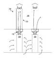
- FIG. 1is a schematic view of an exemplary data center cooling system.
- FIGS. 2A, 2B, and 2Cillustrate one embodiment of a stack having flexible portions on opposing sides of the stack.
- FIG. 3illustrates a cross-sectional area of the stack illustrated in FIGS. 2A, 2B, and 2C .
- FIG. 4illustrates adjustment of a stack having flexible portions.
- FIGS. 5A, 5B, and 5Cillustrate one embodiment of a stack having a flexible portion along the entire perimeter of the stack.
- FIG. 6illustrates an embodiment of a stack having a flexible portion that extends the full height of the stack.
- FIG. 7illustrates one embodiment of a stack including extension ducts.
- FIG. 8illustrates an alternate embodiment of a cooling system.
- data centerincludes any facility or portion of a facility in which computer operations are carried out.
- a data centermay include servers and other systems and components dedicated to specific functions (e.g., e-commerce transactions, database management) or serving multiple functions. Examples of computer operations include information processing, communications, simulations, and operational control.
- computer roommeans a room of a building in which computer systems, such as rack-mounted servers, are operated.
- computer systemincludes any of various computer systems or components thereof.
- a computer systemis a rack-mounted server.
- the term computeris not limited to just those integrated circuits referred to in the art as a computer, but broadly refers to a processor, a server, a microcontroller, a microcomputer, a programmable logic controller (PLC), an application specific integrated circuit, and other programmable circuits, and these terms are used interchangeably herein.
- memorymay include, but is not limited to, a computer-readable medium, such as a random access memory (RAM).
- RAMrandom access memory
- additional input channelsmay include computer peripherals associated with an operator interface such as a mouse and a keyboard.
- other computer peripheralsmay also be used that may include, for example, a scanner.
- additional output channelsmay include an operator interface monitor and/or a printer.
- stackincludes any element or combination of elements that has at least one passageway for transporting, directing, channeling or venting gas (e.g., cooling air) from a system or component in upward direction (at least partially upward).
- a stackmay be in the form of a conduit, tube, duct, plenum, channel, shell, or a combination of one or more such elements.
- Structural elements of a stackmay be flexible, rigid, or a combination thereof.
- a stackmay be tall or short relative to its lateral dimensions (e.g., width, depth, circumference).
- the cross sectional area of a passageway of a stackmay be rectangular, square, circular, or any of various other regular or irregular shapes.
- the cross sectional area of a passageway of a stackmay be uniform over the height of the stack or may vary over the height of the stack.
- a passageway of a stackmay be tapered such that the passageway has greater cross sectional area at the top than at the bottom.
- a stackmay be partially open in its installed condition (e.g., have an open cross section, pores, holes, slots, vents, or other openings).
- to “direct” a fluidincludes to at least partially direct, channel, route, contain, or transport the fluid (e.g., cooling air).
- portincludes an opening or openings that allow a fluid (e.g., cooling air) to enter or exit a component or system.
- a fluide.g., cooling air
- ceilingincludes an overhead interior surface of a room.
- a ceilingmay be in the form of tiles, sheets, panels, wallboard, or other suitable material.
- a ceilingmay be attached to, supported by, and/or suspended from joists, adjacent walls, rods, beams, a roof, columns, or other structural member(s).
- FIG. 1is a schematic view of an exemplary data center cooling system 100 .
- System 100is configured to remove waste heat generation from a data center 102 .
- Data center 102includes at least one high-density equipment rack system, or high-density rack 104 , and at least one low-density equipment rack system, or low-density rack 106 .
- Racks 104 and 106are substantially similar with the exception of a configuration of electronic components (not shown) within each of racks 104 and 106 and the associated waste heat generation.
- Racks 104 and 106include exit ports 107 . Exit ports 107 may be used to remove heated cooling air from racks 104 and 106 .
- waste heat generation from high-density rack 104is greater than waste heat generation from low-density rack 106 due to the greater concentration of waste heat sources within rack 104 as compared to rack 106 .
- Racks 104 and 106are positioned within room 108 of data center 102 .
- Cooling system 100includes air handling sub-system 110 .
- Air handling sub-system 110is coupled in flow communication with room 108 .
- air handling sub-system 110is configured to channel approximately 1,332 cubic meters of air per minute (m 3 /min) (approximately 47,000 cubic feet per minute (ft 3 /min).
- Air handling sub-system 110includes fans 112 .
- Fans 112are coupled to variable frequency drives (VFDs) 114 .
- VFDs 114are coupled to control unit 116 .
- VFDs 114may use pulse width modulation (PWM) methods as are known in the art to modulate the rotational velocity of the associated prime movers. Alternatively, any method of modulation that facilitates operation of system 100 as described herein is used.
- PWMpulse width modulation
- Cooling system 100includes chilled water subsystems 120 .
- Chilled water subsystems 120may be coupled in heat transfer communication with air handling sub-systems 110 .
- Chilled water sub-system 120includes coils 122 .
- Chilled water sub-system 120may be controlled by control unit 116 .
- chilled water subsystems 120may be coupled to a chilled water heat removal system.
- chilled water heat removal systemsinclude a service water subsystem, air-conditions refrigerant sub-system, or a cooling tower sub-system.
- control unit 116is configured with at least one algorithm to receive measurement signals and modulate VFDs, as well as control elements in chilled water sub-system 120 , to maintain a predetermined differential temperature across racks 104 and 106 .
- Data center 102includes raised floor 124 that at least partially forms room 108 .
- Data center 102also includes lower floor 126 that cooperates with floor 124 to at least partially form data center air supply plenum 128 .
- Floor 124is configured to support data center components that are positioned within room 108 that include, but are not limited to, racks 104 and 106 .
- At least one high-density air flow restriction device 130is positioned within floor 124 and is configured such that a first predetermined rate of air flow at a first predetermined velocity is facilitated to impinge on each of racks 104 .
- At least one low-density air flow restriction device 132is positioned within floor 124 and is configured such that a second predetermined rate of air flow at a second predetermined velocity is facilitated to impinge on each of racks 106 .
- Devices 130 and 132facilitate coupling plenum 128 in flow communication with room 108 .
- devices 130 and 132are gratings fabricated to facilitate attaining the associated predetermined air flows and velocities.
- devices 130 and 132are any devices that facilitate operation of cooling system 100 as described herein, including, but not limited to, perforated floor tiles wherein such perforations are dimensioned and positioned to attain the associated predetermined air flows and velocities.
- racks 104 and 106are configured to facilitate channeling heat-removing airflow into and throughout racks 104 and 106 from devices 130 and 132 , respectively. Airflow is channeled such that substantially all of the waste heat generated by racks 104 and 106 is channeled out of racks 104 and 106 through exit ports 107 in the associated tops of racks 104 and 106 .
- Data center 102includes drop ceiling 140 that at least partially forms room 108 .
- Data center 102further includes upper ceiling 142 that cooperates with drop ceiling 140 to at least partially form a data center overhead air discharge plenum 144 .
- airpasses through drop ceiling 140 through ceiling openings 146 .
- one or more of openingsis formed by leaving a ceiling tile out of an array of tiles that the forms the ceiling.
- openings 146are 2 ⁇ 2 foot square openings.
- openings 146include vents that can be manually or automatically adjusted to vary airflow.
- openings 146include flow restriction devices.
- Stacks 150are provided between the top of racks 104 and 106 and ceiling 142 . Stacks 150 may be coupled to ceiling 142 at the top of stack 150 and coupled to rack 104 or 106 and the bottom of stack 150 . Stacks 150 may at least partially segregate cooling air leaving rack exit ports 107 from room ambient air 154 in room 108 . In some embodiments, stacks 150 are provided on all of racks in a computer room. In other embodiments, stacks may be provided on only one, or only some, of the racks in a computer room. In one embodiment, stacks 150 isolate all the cooling air exiting each rack from room ambient air 154 , for all the racks in the data room.
- Control unit 116may be programmed to control devices in handling sub-systems 110 and/or chilled water sub-systems 120 .
- Control unit 116is configured to sense and measure a plurality of environmental parameters and modulate a differential temperature across each of racks 104 and 106 .
- Control unit 116is in data communication with temperature sensors 160 , 162 , and 164 and humidity sensors 166 , 168 , and 170 .
- Devices in air handling sub-system 110 and chilled water sub-systems 120may be controlled automatically, manually, or a combination thereof.
- control unit 116includes at least one programmable logic controller.
- the PLCmay, among other things, open and close dampers in air handling system 110 based upon command signals from an operator to channel air flow through data center 102 as necessary for the prevailing operational conditions. Alternatively, the PLC may modulate dampers between fully open and fully closed positions to modulate airflow.
- Cooling system 100also includes a plurality of temperature measurement devices that, in one embodiment, are thermocouples.
- the temperature measurement devicesinclude, but not be limited to, resistance temperature detectors (RTDs) and any device that facilitate operation of cooling system 100 as described herein.
- RTDsresistance temperature detectors
- a chilled water thermocouplemay be positioned within chilled water subsystem 120 to facilitate measuring a temperature of the chilled water upon discharge from a heat exchanger. In the one embodiment, such chilled water temperatures are controlled to approximately 5.6 degrees Celsius (° C.) (42 degrees Fahrenheit (° F.)).
- Cooling system 100includes temperature sensor 160 and humidity sensor 162 positioned within plenum 128 . Temperature sensor 160 and humidity sensor 162 may be configured to facilitate measuring a temperature of air within plenum 128 prior to being channeled towards racks 104 and 106 . In the one embodiment, a plurality of thermocouples are positioned approximately 3 meters (m) (10 feet (ft)) apart to facilitate measurement redundancy and measurement averaging across plenum 128 . Alternatively, any number of thermocouples positioned anywhere within plenum 128 that facilitates operation of system 100 as described herein is used.
- Cooling system 100also includes temperature sensor 164 and humidity sensor 166 positioned within plenum 144 . Temperature sensor 164 and humidity sensor 166 may be configured to facilitate measuring temperature and humidity of air within plenum 144 subsequent to being channeled from racks 104 and 106 . In one embodiment, a plurality of thermocouples are positioned approximately 3 meters (m) (10 feet (ft)) apart to facilitate redundancy and measurement averaging in a manner similar to that used with thermocouples within plenum 128 . Alternatively, any number of thermocouples positioned anywhere within plenum 144 that facilitates operation of cooling system 100 as described herein is used.
- Cooling system 100also includes temperature sensor 168 and humidity sensor 170 positioned outside data center 102 . Temperature sensor 168 and humidity sensor 170 may be configured to facilitate measuring temperature and humidity of outside ambient air, for use in controlling operating characteristics of cooling system 100 .
- an air handling sub-system 110may include a system of dampers that allows cooling air to either be drawn from outside air and then exhausted, or recycled within the data center.
- a control unitmay operate the dampers to either use outside air or recycled air, depending on, among other things, the entropy of the outside air.
- airis channeled from duct 174 into plenum 128 such that a predetermined substantially static pressure is maintained within plenum 128 .
- a static pressuremay be measured in plenum 128 .
- Airis then channeled upward from plenum 128 through devices 130 and 132 , wherein devices 130 and 132 facilitate channeling predetermined air flows that impinge on racks 104 and 106 .
- the temperature of air discharged from plenum 128is approximately 10° C. (50° F.).
- Airis subsequently channeled across and through racks 104 and 106 wherein the air absorbs at least some of the waste heat generated within racks 104 and 106 .
- Warmed airis channeled upward from racks 104 and 106 through exit ports 107 and through stacks 150 and into plenum 144 , where the warmed air may be partially mixed. Air is channeled from plenum 144 .
- the warmed airis subsequently channeled into a duct for another transit through air handling subsystem 110 , channeled to another air handling system, or rejected to outside ambient air.
- FIG. 1For illustrative purposes, only one air handling sub-system is shown in FIG. 1 .
- the number of air handling sub-systems in a cooling systemmay vary, however.
- a cooling systemincludes many air handling sub-systems.
- cross-over ductsmay be provided (e.g., on the supply side, the return side, or both) to allow cooling air from air handling sub-systems to be distributed and/or redirected within a data center or among data centers.
- Air handling sub-systemsmay be commonly controlled, separately controlled, or a combination thereof. In certain embodiments, some or all of the air handling sub-systems for a data center are provided with outside air vents.
- FIGS. 2A, 2B, and 2Cillustrate one embodiment of a stack having flexible portions on opposing sides of the stack.
- Stack 150includes upper duct portion 180 , flexible portion 182 , and lower duct portion 184 .
- the top of upper duct portion 180includes exit opening 186 .
- the bottom of lower duct portion 184includes inlet opening 188 .
- Upper duct portion 180includes tabs 190 and fasteners 192 .
- Tabs 190may accommodate fasteners 192 .
- Fasteners 192may be used to secure stack 150 to ceiling 144 (see, for example, drop ceiling 140 in FIG. 1 ).
- fasteners 192are captive fasteners.
- Lower duct portion 184may include magnets 194 .
- Magnets 194may be coupled to the top of a rack system (e.g., rack 104 shown in FIG. 1 ). Magnets may allow for adjustment in the position of inlet opening 188 relative to the rack system.
- lower duct portion 184may be aligned such that inlet opening 188 is aligned with an exit port of a rack system (e.g., exit port 107 shown in FIG. 1 ).
- Flexible portion 182may be made of a flexible material.
- flexible portion 182is made of an expandable fabric.
- flexible portion 182is made of a plastic (e.g., polymeric) sheet material.
- a plastic sheet materialhas a thickness of about 4 mm.
- Other suitable materialsmay include metal or rubber.
- the flexible materialmay be a fire-retardant material.
- flexible portion 182may include a bellows-type construction (e.g., with corrugations that allow the material to be shortened or lengthened).
- Flexible portion 182may be permanently attached to upper duct portion 180 and lower duct portion 184 , or may be separable or removable from either or both of upper duct portion 180 and lower duct portion 184 .
- FIG. 3illustrates a cross-sectional area of the stack shown in FIGS. 2A, 2B , and 2 C.
- a cross-sectional area of a passagewaymay increase with the height of the passageway over at least a portion of the height of the passageway.
- the width of passageway 198increases from the lower edge of flexible portion 182 to the upper edge of flexible portion 182 .
- an opening at an inlet portion of a stackhas a smaller cross sectional area than an opening of at exit portion of the stack.
- an inlet openingmay be about 6 inches by 12 inches, and an exit opening may be about 24 inches by 24 inches.
- a passageway in a stackmay produce a chimney effect, thereby promoting a flow of exit cooling air from a rack system.
- a stackmay include a funnel-shaped passageway whose cross-sectional area increases with height. The funnel-shaped passageway may accelerate the flow of exit air in the passageway.
- the passage of air from the stack into an overhead discharge plenum above the ceiling line(which has a larger cross sectional area than the exit opening of the stack) may further promote the flow of air from a rack system.
- stack 150is described as coupled to ceiling with fasteners, and coupled to the rack with magnets, in other embodiments a stack may be coupled in a variety of other ways.
- a lower portion of a stackmay be pinned or bolted to the rack.
- an upper portion of a stackmay be attached to a ceiling with clips or hangers.
- a lower portion of a stackis adjustable relative to the upper portion.
- FIG. 4illustrates adjustment of a stack having flexible portions.
- Flexible portion 182 of stack 150may allow lower duct portion 184 to be moved laterally relative to upper duct portion 180 (e.g., from initial position 199 to adjusted position 197 ). Adjustment of lower duct portion 184 may allow inlet opening 188 to be aligned with an exit port of a rack system (e.g., racks 104 or 106 ) while upper duct portion 180 is attached to a ceiling.
- flexible portion 182may allow for a height adjustment of stack (e.g., to accommodate differences in spacing between various racks and a ceiling.)
- FIGS. 5A, 5B, and 5Cillustrate one embodiment of a stack having a flexible portion along the entire perimeter of the stack.
- Stack 200includes upper duct portion 202 , flexible portion 204 , and lower duct portion 206 .
- Flexible portion 204may extend around the entire perimeter of upper duct portion 202 and lower duct portion 206 .
- Lower duct portion 206may be laterally adjustable in all directions (e.g., within a horizontal plane) relative to upper duct portion 202 .
- FIG. 6illustrates an embodiment of a stack having a flexible portion that extends the full height of the stack.
- Stack 210includes flexible portion 212 , exit opening 214 , and inlet opening 216 .
- the size and/or shape of inlet opening 216may be adjusted by manipulating flexible portion 212 proximate to the inlet opening.
- stack 150is shown as a combination of duct sections and an intermediate flexible portion
- a stackmay in other embodiments be of different constructions.
- a stackmay be in form of a curtain or a set of curtains.
- the curtain or curtainmay be arranged to form a passageway (sealed or unsealed) to direct exit air from a rack to the ceiling of a computer room.
- a stackis a funnel-shaped tube.
- the tubemay be formed from plastic sheet, fabric, or other suitable material. Magnets may be used to couple the inlet portion of the stack exit ports.
- a stackmay be coupled to exit ports on a front, back, or side of a rack.
- the flexible portione.g., fabric curtain
- the flexible portionmay be manipulated to allow magnets on the stack to couple with the rack such that air from the exit ports is directed into a passageway of the stack.
- a stackincludes a combination of members selected to bridge a gap elements of a cooling system.
- FIG. 7illustrates an embodiment of a stack including extension ducts.
- stack 220includes a stack similar to stack 150 shown in FIGS. 2A, 2B, and 2C .
- Stack 220further includes upper extension duct 222 and lower extension duct 224 .
- the heights of upper extension duct 222 and/or lower extension duct 224may be selected to achieve an appropriate overall height of stack 220 .
- FIG. 8illustrates an alternate embodiment of a cooling system.
- Cooling system 230may be similar to cooling system 100 shown in FIG. 1 , except that exit air from rack 104 is directed into exit duct 232 .
- Exit duct 232may segregate the exit air of rack 104 from the exit air of rack 106 and other racks in the room.
- cooler air in overhead plenum 144may be recirculated to room 108 , while warmer air in duct 232 may be purged into the ambient outside air.
- exit air from two or more racksmay be merged in a single duct. The merged air may be segregated from air an overhead air discharge plenum.
- air from all the racks in a roommay be collected into one or more ducts.
Landscapes
- Engineering & Computer Science (AREA)
- Microelectronics & Electronic Packaging (AREA)
- Physics & Mathematics (AREA)
- Thermal Sciences (AREA)
- Computer Hardware Design (AREA)
- General Engineering & Computer Science (AREA)
- Cooling Or The Like Of Electrical Apparatus (AREA)
Abstract
Description
1. Field of the Invention
The present invention relates generally to cooling systems and more particularly, to methods and apparatus for cooling electronic components.
2. Description of the Related Art
Some known electronic components generate waste heat energy when energized. This heat energy should be removed to mitigate a potential for component overheating and subsequent malfunction. Computer systems typically include a number of such components, or waste heat sources, that include, but are not limited to, printed circuit boards, mass storage devices, power supplies, and processors. For example, one personal computer system may generate 100 watts to 150 watts of waste heat and some larger computers with multiple processors may generate 250 watts of waste heat. Some known computer systems include a plurality of such larger, multiple-processor computers that are configured into rack-mounted components, and then are subsequently positioned within a racking system. Some known racking systems include 40 such rack-mounted components and such racking systems will therefore generate as much as 10 kilowatts of waste heat. Moreover, some known data centers include a plurality of such racking systems.
Some known data centers include methods and apparatus configured to facilitate waste heat removal from a plurality of racking systems. Moreover, some known data centers include a plurality of racking systems that have a plurality of configurations that are non-uniform with respect to component density and usage such that each racking system generates waste heat at a non-uniform rate as compared to the remainder of the racking systems. In such data centers, application of uniform heat removal methods and apparatus to such non-uniform waste heat generation sources may not be fully efficient and effective in waste heat removal.
In many computer rooms, cooling air carrying waste heat from the racking systems is vented to the room ambient air above the racking systems. At the same time, an air handling system for the room draws air out of the room through vents in the ceiling or walls of the room, thereby maintaining a steady-state flow of air in the room. Before the exit air carrying the waste racking system reaches the vents, the exit air from the racking systems mixes with the room ambient air. Some of the waste heat from the exit air is transferred into the room ambient air, which causes the ambient temperature in the room to rise and may create short-cycling and other inefficiencies in cooling of the racking systems.
Various embodiments of apparatus and methods of cooling computers in a data center are disclosed. In an embodiment, a stack for directing cooling air from a rack-mounted computer system includes an inlet portion, an exit portion, and a flexible portion between the inlet portion and the exit portion. The inlet portion of the stack couples with a rack system at an exit port of the rack system. The exit portion of the stack couples with a ceiling of a data room at an opening in the ceiling.
In an embodiment, a cooling system for a computer room includes a forced air system. The forced air system moves cooling air through computers in one or more rack systems in the computer room. Stacks are coupled between the rack systems and the ceiling of the computer room. The stacks direct cooling air exiting from exit ports on the rack systems to openings in the ceiling.
In an embodiment, a method of cooling rack-mounted computers in a computer room includes moving cooling air through computers in a rack system. The cooling air is directed away from the rack system to an opening in a ceiling of the computer room such that the exiting cooling air is segregated from room ambient air in the computer room.
While the invention is susceptible to various modifications and alternative forms, specific embodiments thereof are shown by way of example in the drawings and will herein be described in detail. It should be understood, however, that the drawings and detailed description thereto are not intended to limit the invention to the particular form disclosed, but on the contrary, the intention is to cover all modifications, equivalents and alternatives falling within the spirit and scope of the present invention as defined by the appended claims. The headings used herein are for organizational purposes only and are not meant to be used to limit the scope of the description or the claims. As used throughout this application, the word “may” is used in a permissive sense (i.e., meaning having the potential to), rather than the mandatory sense (i.e., meaning must). Similarly, the words “include,” “including,” and “includes” mean including, but not limited to.
As used herein, “data center” includes any facility or portion of a facility in which computer operations are carried out. A data center may include servers and other systems and components dedicated to specific functions (e.g., e-commerce transactions, database management) or serving multiple functions. Examples of computer operations include information processing, communications, simulations, and operational control.
As used herein, “computer room” means a room of a building in which computer systems, such as rack-mounted servers, are operated.
As used herein, “computer system” includes any of various computer systems or components thereof. One example of a computer system is a rack-mounted server. As used herein, the term computer is not limited to just those integrated circuits referred to in the art as a computer, but broadly refers to a processor, a server, a microcontroller, a microcomputer, a programmable logic controller (PLC), an application specific integrated circuit, and other programmable circuits, and these terms are used interchangeably herein. In various embodiments, memory may include, but is not limited to, a computer-readable medium, such as a random access memory (RAM). Alternatively, a compact disc-read only memory (CD-ROM), a magneto-optical disk (MOD), and/or a digital versatile disc (DVD) may also be used. Also, additional input channels may include computer peripherals associated with an operator interface such as a mouse and a keyboard. Alternatively, other computer peripherals may also be used that may include, for example, a scanner. Furthermore, in the some embodiments, additional output channels may include an operator interface monitor and/or a printer.
As used herein, “stack” includes any element or combination of elements that has at least one passageway for transporting, directing, channeling or venting gas (e.g., cooling air) from a system or component in upward direction (at least partially upward). A stack may be in the form of a conduit, tube, duct, plenum, channel, shell, or a combination of one or more such elements. Structural elements of a stack may be flexible, rigid, or a combination thereof. A stack may be tall or short relative to its lateral dimensions (e.g., width, depth, circumference). The cross sectional area of a passageway of a stack may be rectangular, square, circular, or any of various other regular or irregular shapes. The cross sectional area of a passageway of a stack may be uniform over the height of the stack or may vary over the height of the stack. For example, a passageway of a stack may be tapered such that the passageway has greater cross sectional area at the top than at the bottom. In certain embodiments, a stack may be partially open in its installed condition (e.g., have an open cross section, pores, holes, slots, vents, or other openings).
As used herein, to “direct” a fluid includes to at least partially direct, channel, route, contain, or transport the fluid (e.g., cooling air).
As used herein, “port” includes an opening or openings that allow a fluid (e.g., cooling air) to enter or exit a component or system.
As used herein, “ceiling” includes an overhead interior surface of a room. A ceiling may be in the form of tiles, sheets, panels, wallboard, or other suitable material. A ceiling may be attached to, supported by, and/or suspended from joists, adjacent walls, rods, beams, a roof, columns, or other structural member(s).
In some embodiments,chilled water subsystems 120 may be coupled to a chilled water heat removal system. Examples of chilled water heat removal systems include a service water subsystem, air-conditions refrigerant sub-system, or a cooling tower sub-system.
In an embodiment,control unit 116 is configured with at least one algorithm to receive measurement signals and modulate VFDs, as well as control elements inchilled water sub-system 120, to maintain a predetermined differential temperature acrossracks
In one embodiment,devices devices cooling system 100 as described herein, including, but not limited to, perforated floor tiles wherein such perforations are dimensioned and positioned to attain the associated predetermined air flows and velocities. Also, in one embodiment, racks104 and106 are configured to facilitate channeling heat-removing airflow into and throughoutracks devices racks racks exit ports 107 in the associated tops ofracks
In certain embodiments,control unit 116 includes at least one programmable logic controller. The PLC may, among other things, open and close dampers inair handling system 110 based upon command signals from an operator to channel air flow throughdata center 102 as necessary for the prevailing operational conditions. Alternatively, the PLC may modulate dampers between fully open and fully closed positions to modulate airflow.
In some embodiments, data from one or more temperature, humidity, or pressure sensors is used to determine an air source. For example, anair handling sub-system 110 may include a system of dampers that allows cooling air to either be drawn from outside air and then exhausted, or recycled within the data center. A control unit may operate the dampers to either use outside air or recycled air, depending on, among other things, the entropy of the outside air.
In one embodiment, air is channeled fromduct 174 intoplenum 128 such that a predetermined substantially static pressure is maintained withinplenum 128. A static pressure may be measured inplenum 128. Air is then channeled upward fromplenum 128 throughdevices devices racks plenum 128 is approximately 10° C. (50° F.).
Air is subsequently channeled across and throughracks racks racks exit ports 107 and throughstacks 150 and intoplenum 144, where the warmed air may be partially mixed. Air is channeled fromplenum 144. The warmed air is subsequently channeled into a duct for another transit throughair handling subsystem 110, channeled to another air handling system, or rejected to outside ambient air.
For illustrative purposes, only one air handling sub-system is shown inFIG. 1 . The number of air handling sub-systems in a cooling system may vary, however. In some embodiments, a cooling system includes many air handling sub-systems. In facilities with multiple air handling sub-systems and/or multiple data centers, cross-over ducts may be provided (e.g., on the supply side, the return side, or both) to allow cooling air from air handling sub-systems to be distributed and/or redirected within a data center or among data centers. Air handling sub-systems may be commonly controlled, separately controlled, or a combination thereof. In certain embodiments, some or all of the air handling sub-systems for a data center are provided with outside air vents.
Although in the embodiment shown inFIGS. 2A, 2B, and 2C ,stack 150 is described as coupled to ceiling with fasteners, and coupled to the rack with magnets, in other embodiments a stack may be coupled in a variety of other ways. For example, a lower portion of a stack may be pinned or bolted to the rack. As another example, an upper portion of a stack may be attached to a ceiling with clips or hangers.
In some embodiments, a lower portion of a stack is adjustable relative to the upper portion.FIG. 4 illustrates adjustment of a stack having flexible portions.Flexible portion 182 ofstack 150 may allowlower duct portion 184 to be moved laterally relative to upper duct portion180 (e.g., from initial position199 to adjusted position197). Adjustment oflower duct portion 184 may allowinlet opening 188 to be aligned with an exit port of a rack system (e.g., racks104 or106) whileupper duct portion 180 is attached to a ceiling. In certain embodiments,flexible portion 182 may allow for a height adjustment of stack (e.g., to accommodate differences in spacing between various racks and a ceiling.)
Although in the embodiment shown relative toFIGS. 2A, 2B, and 2C and 4A, 4B, and 4C ,stack 150 is shown as a combination of duct sections and an intermediate flexible portion, a stack may in other embodiments be of different constructions. For example, a stack may be in form of a curtain or a set of curtains. The curtain or curtain may be arranged to form a passageway (sealed or unsealed) to direct exit air from a rack to the ceiling of a computer room. In another embodiment, a stack is a funnel-shaped tube. The tube may be formed from plastic sheet, fabric, or other suitable material. Magnets may be used to couple the inlet portion of the stack exit ports. In certain embodiments, a stack may be coupled to exit ports on a front, back, or side of a rack. The flexible portion (e.g., fabric curtain) may be manipulated to allow magnets on the stack to couple with the rack such that air from the exit ports is directed into a passageway of the stack.
In certain embodiments, a stack includes a combination of members selected to bridge a gap elements of a cooling system.FIG. 7 illustrates an embodiment of a stack including extension ducts. In this example, stack220 includes a stack similar to stack150 shown inFIGS. 2A, 2B, and 2C .Stack 220 further includesupper extension duct 222 andlower extension duct 224. The heights ofupper extension duct 222 and/orlower extension duct 224 may be selected to achieve an appropriate overall height ofstack 220.
Although the embodiments above have been described in considerable detail, numerous variations and modifications will become apparent to those skilled in the art once the above disclosure is fully appreciated. It is intended that the following claims be interpreted to embrace all such variations and modifications.
Claims (23)
1. A cooling system for directing cooling air from a rack-mounted computer system, comprising:
a stack, comprising:
an inlet configured to couple with a rack system at an exit of the rack;
a lower duct portion;
an exit of the stack configured to couple with a ceiling at an opening in the ceiling, wherein the opening in the ceiling includes a flow restriction device; and
an upper duct portion configured to extend downwardly from the ceiling; and
an exit duct, coupled with the exit of the stack, and configured to extend into and through a ceiling plenum above the opening in the ceiling, wherein the exit duct forms an enclosure configured to segregate exit air exiting the rack system and passing through the exit duct from air circulating within the ceiling plenum and air entering the ceiling plenum from one or more other rack systems, such that air circulating within the ceiling plenum and air entering the ceiling plenum from one or more other rack systems is recirculated and the exit air passing through the exit duct passes into ambient air outside the ceiling plenum;
a flexible portion of increasing passage size coupled between the lower duct portion and the upper duct portion, wherein the flexible portion is coupled with the upper duct portion at a point below the ceiling, wherein the lower duct portion is configured to direct cooling air from the inlet to the flexible portion, wherein the flexible portion is configured to direct cooling air from the lower duct portion to the upper duct portion,
wherein the lower duct portion comprises a lower duct cross-sectional area, wherein the cross-sectional area of the flexible portion increases from a first cross-sectional area where the flexible portion couples to the lower duct portion to a second cross-sectional area where the flexible portion couples to the upper duct portion, wherein the upper duct portion is above the flexible portion, wherein the upper duct portion comprises a passageway configured to direct air that is downstream from the flexible portion of increasing passage size through the opening in the ceiling, wherein the upper duct portion comprises an upper duct cross-sectional area that is larger than the second, increased cross sectional area of the flexible portion.
2. The cooling system ofclaim 1 , wherein the flexible portion is adjustable to laterally adjust the lower duct portion of the stack relative to upper duct portion.
3. The cooling system ofclaim 1 , wherein the flexible portion is adjustable to adjust a size of an opening of the inlet.
4. The cooling system ofclaim 1 , wherein the flexible portion is adjustable to alter a shape of an opening of the inlet.
5. The cooling system ofclaim 1 , further comprising at least one magnet portion configured to couple the inlet to rack system.
6. The cooling system ofclaim 1 , further comprising at least one tab to couple the exit to the ceiling.
7. The cooling system ofclaim 1 , wherein the flexible portion comprises a fabric.
8. The cooling system ofclaim 1 , wherein the flexible portion comprises an expandable fabric.
9. The cooling system ofclaim 1 , wherein the flexible portion comprises a plastic sheet material.
10. A cooling system for rack-mounted computers in a computer room, comprising:
a forced air system configured to move cooling air through one or more computers in one or more rack systems in the computer room, wherein the forced air system comprises an air handling system configured to force air into the computer room through a raised floor of the computer room;
one or more stacks coupled between one or more of the rack systems and a ceiling of the computer room, the stacks being configured to direct cooling air exiting from one or more exits on one or more of the rack systems to one or more openings in the ceiling, wherein at least one of the stacks comprises:
a lower duct portion;
an upper duct portion configured to extend downwardly from the ceiling; and
a flexible portion of increasing passage size coupled between the lower duct portion and the upper duct portion, wherein the flexible portion is coupled with the upper duct portion at a point below the ceiling, wherein the lower duct portion is configured to direct cooling air from an inlet to the flexible portion, wherein the flexible portion is configured to direct cooling air from the lower duct portion to the upper duct portion, and
wherein the lower duct portion comprises a lower duct cross-sectional area, wherein the cross-sectional area of the flexible portion increases from a first cross-sectional area where the flexible portion couples to the lower duct portion to a second cross-sectional area where the flexible portion couples to the upper duct portion, wherein the upper duct portion is above the flexible portion, wherein the upper duct portion comprises a passageway configured to direct air that is downstream from the flexible portion of increasing passage size through the opening in the ceiling, wherein the upper duct portion comprises an upper duct cross-sectional area that is larger than the second, increased cross sectional area of the flexible portion;
a ceiling plenum above the opening in the ceiling; and
an exit duct configured to extend into and through the ceiling plenum, wherein the exit duct forms an enclosure configured to segregate exit air exiting a rack system coupled to the at least one stack and passing through the exit duct from air circulating within the ceiling plenum and air entering the ceiling plenum from one or more other rack systems in the computer room, such that air circulating within the ceiling plenum and air entering the ceiling plenum from one or more other rack systems is recirculated to the computer room and air passing through the exit duct passes into ambient air outside the ceiling plenum.
11. The system ofclaim 10 , wherein at least one of the stacks is configured to at least partially segregate the exiting cooling air from ambient air in the computer room.
12. The system ofclaim 10 , wherein at least one passageway of the stack is configured to produce a chimney effect in the stack.
13. The system ofclaim 10 , wherein the forced air system comprises an air handling system configured to move air in the computer room.
14. The system ofclaim 13 , wherein the air handling system is configured to force air into the computer room through the raised floor of the computer room.
15. The system ofclaim 13 , wherein the air handling system is configured to draw air out of the computer room through the ceiling of the computer room.
16. The system ofclaim 10 , wherein the forced air system comprises at least one fan in at least one of the rack systems, wherein the at least one fan is configured to move air through the rack system and out through at least one exit of the rack system.
17. The system ofclaim 10 , wherein the upper duct portion is configured to couple to the ceiling.
18. The system ofclaim 17 , wherein the flexible portion is adjustable to align the lower duct portion of the stack with the upper duct portion of the rack system while the upper duct portion is coupled to the ceiling.
19. The system ofclaim 10 , wherein the stack comprises an inlet portion configured to couple to the rack system and an exit portion configured to couple to the ceiling, wherein the exit is larger than the inlet.
20. The system ofclaim 10 , wherein the forced air system comprises:
an air handling system comprising a control system; and
at least one temperature sensor or at least one humidity sensor in the space above the ceiling,
wherein the at least one temperature sensor or the at least one humidity sensor is coupled to the control system, wherein the control system is configured to modify at least one air flow characteristic of the air handling system in response to data from at least one temperature sensor or the at least one humidity sensor.
21. The system ofclaim 10 , wherein the forced air system comprises:
an air handling system comprising a control system; and
at least one humidity sensor configured to measure ambient outside air,
wherein the at least one humidity sensor is coupled to the control system, wherein the control system is configured to modify at least one air flow characteristic of the air handling system in response to data from the at least one humidity sensor.
22. The system ofclaim 10 , wherein the flexible portion defines a passageway having a rectangular cross section, wherein the rectangular cross section has a uniform length and a varying width, wherein the width increases from a first width at the first cross sectional area to a second width at the second cross-sectional area.
23. The system ofclaim 10 , wherein the upper duct portion and the lower duct portion each comprise a rectangular sheet metal duct.
Priority Applications (2)
| Application Number | Priority Date | Filing Date | Title |
|---|---|---|---|
| US12/163,146US9426903B1 (en) | 2008-06-27 | 2008-06-27 | Cooling air stack for computer equipment |
| US15/243,538US9918412B2 (en) | 2008-06-27 | 2016-08-22 | Cooling air stack for computer equipment |
Applications Claiming Priority (1)
| Application Number | Priority Date | Filing Date | Title |
|---|---|---|---|
| US12/163,146US9426903B1 (en) | 2008-06-27 | 2008-06-27 | Cooling air stack for computer equipment |
Related Child Applications (1)
| Application Number | Title | Priority Date | Filing Date |
|---|---|---|---|
| US15/243,538DivisionUS9918412B2 (en) | 2008-06-27 | 2016-08-22 | Cooling air stack for computer equipment |
Publications (1)
| Publication Number | Publication Date |
|---|---|
| US9426903B1true US9426903B1 (en) | 2016-08-23 |
Family
ID=56683364
Family Applications (2)
| Application Number | Title | Priority Date | Filing Date |
|---|---|---|---|
| US12/163,146Active2032-08-04US9426903B1 (en) | 2008-06-27 | 2008-06-27 | Cooling air stack for computer equipment |
| US15/243,538ActiveUS9918412B2 (en) | 2008-06-27 | 2016-08-22 | Cooling air stack for computer equipment |
Family Applications After (1)
| Application Number | Title | Priority Date | Filing Date |
|---|---|---|---|
| US15/243,538ActiveUS9918412B2 (en) | 2008-06-27 | 2016-08-22 | Cooling air stack for computer equipment |
Country Status (1)
| Country | Link |
|---|---|
| US (2) | US9426903B1 (en) |
Cited By (12)
| Publication number | Priority date | Publication date | Assignee | Title |
|---|---|---|---|---|
| US20150065028A1 (en)* | 2005-09-19 | 2015-03-05 | Chatsworth Products, Inc. | Ducted exhaust equipment enclosure |
| USD790053S1 (en)* | 2015-08-27 | 2017-06-20 | Mustang Sampling, Llc | Chromatograph exhaust vent back pressure diffuser |
| US9801309B2 (en) | 2005-09-19 | 2017-10-24 | Chatsworth Products, Inc. | Ducted exhaust equipment enclosure |
| US9918412B2 (en)* | 2008-06-27 | 2018-03-13 | Amazon Technologies, Inc. | Cooling air stack for computer equipment |
| EP3370491A1 (en)* | 2017-03-03 | 2018-09-05 | Apelsin Enterprises GmbH | Assembly of a cooling system for cooling at least one server rack in a room |
| US10154614B1 (en)* | 2014-06-04 | 2018-12-11 | Amazon Technologies, Inc. | Air handling unit intake air preheat system and method |
| US10440847B2 (en) | 2005-09-19 | 2019-10-08 | Chatsworth Products, Inc. | Vertical exhaust duct for electronic equipment enclosure |
| US10709039B2 (en) | 2011-12-09 | 2020-07-07 | Chatsworth Products, Inc. | Data processing equipment structure |
| US11212928B2 (en) | 2005-09-19 | 2021-12-28 | Chatsworth Products, Inc. | Vertical exhaust duct for electronic equipment enclosure |
| US11259446B2 (en) | 2005-09-19 | 2022-02-22 | Chatsworth Products, Inc. | Vertical exhaust duct for electronic equipment enclosure |
| US20220167523A1 (en)* | 2020-11-25 | 2022-05-26 | Digital Porpoise, Llc | Cooling system for a data center that includes an offset cooling technology |
| US20240247664A1 (en)* | 2022-04-27 | 2024-07-25 | Shanghai Flextail Technology Co., Ltd. | Air pump cover and air pump |
Families Citing this family (1)
| Publication number | Priority date | Publication date | Assignee | Title |
|---|---|---|---|---|
| EP3720262B1 (en) | 2019-04-04 | 2021-12-15 | Carrier Corporation | Air management system for room containing electrical equipment and method of cooling such a room |
Citations (202)
| Publication number | Priority date | Publication date | Assignee | Title |
|---|---|---|---|---|
| US1031456A (en)* | 1911-09-30 | 1912-07-02 | Jay Leslie | Ventilating device. |
| US1586706A (en)* | 1925-08-24 | 1926-06-01 | Holland Furnace Co | Nozzle connection for large-sized suction hose |
| US3467411A (en)* | 1966-12-19 | 1969-09-16 | Christian P Klapproth Jr | Threaded sheet metal fitting |
| US3481485A (en) | 1968-03-18 | 1969-12-02 | Zero Max Ind Inc | Adjustable shelf support device |
| US3807572A (en) | 1972-05-12 | 1974-04-30 | Pitney Bowes Inc | Adjustable compartment size storage unit |
| US3834423A (en)* | 1972-05-30 | 1974-09-10 | Acme Hamilton Mfg Corp | Contractile-extensible conduit and method of making same |
| US3915477A (en)* | 1974-05-03 | 1975-10-28 | Automation Ind Inc | Duct fitting |
| US4082092A (en)* | 1976-05-11 | 1978-04-04 | Foster Beatrice D | Vacuum cabinet and gas venting shield |
| US4081915A (en)* | 1976-06-04 | 1978-04-04 | Materniak Gize | Exhaust system for laundry dryer |
| US4328897A (en) | 1978-11-08 | 1982-05-11 | Vero Electronics Gmbh | Rack for accommodating circuit boards |
| US4448111A (en)* | 1981-01-02 | 1984-05-15 | Doherty Robert | Variable venturi, variable volume, air induction input for an air conditioning system |
| US4585122A (en) | 1985-01-28 | 1986-04-29 | Racal Data Communications, Inc. | Secure housing arrangement for electronic apparatus |
| US4864469A (en) | 1988-04-11 | 1989-09-05 | Tektronix, Inc. | Support structure |
| US4926291A (en) | 1989-07-31 | 1990-05-15 | Western Digital Corporation | Data storage mounting assembly |
| US5080403A (en)* | 1990-12-10 | 1992-01-14 | Paoluccio John A | Apparatus for connecting a branch duct to another duct |
| US5208722A (en) | 1988-12-29 | 1993-05-04 | Compaq Computer Corporation | Tower system unit with angled drive bay |
| US5240288A (en)* | 1992-04-20 | 1993-08-31 | General Plastics, Inc. | Double air duct boot |
| US5294049A (en)* | 1993-02-22 | 1994-03-15 | Temp-Vent Corporation | Power temp vent duct system |
| EP0546211B1 (en) | 1991-12-11 | 1994-07-20 | Hewlett-Packard GmbH | Chassis of a device |
| US5412534A (en) | 1993-03-20 | 1995-05-02 | International Business Machines Corporation | Modular housing |
| US5506750A (en) | 1993-04-22 | 1996-04-09 | Bull S.A. | Mass memory subsystem having plates with pluralities of disk drives connected to central electronic cards |
| US5518277A (en)* | 1991-09-03 | 1996-05-21 | Gcs Innovations, Inc. | Single piece duct connector for leakfree attachment to sidewall of highly flexible trunkline duct |
| US5621890A (en) | 1991-06-21 | 1997-04-15 | John Notarianni | Method and apparatus for transferring data between a host device and a plurality of portable computers |
| US5644472A (en) | 1995-09-06 | 1997-07-01 | Micron Electronics, Inc. | Computer component carrier that directs airflow to critical components |
| US5751549A (en) | 1996-06-26 | 1998-05-12 | Sun Microsystems, Inc. | Hard disk drive assembly which has a plenum chamber and a fan assembly that is perpendicular to a rack chamber |
| US5772500A (en) | 1996-12-20 | 1998-06-30 | Symbios, Inc. | Compact ventilation unit for electronic apparatus |
| WO1998034450A1 (en) | 1997-02-04 | 1998-08-06 | Telia Ab (Publ) | Method and device for cooling of electronic/computer equipment and use thereof |
| US5796580A (en) | 1993-04-13 | 1998-08-18 | Hitachi, Ltd. | Air-cooled information processing apparatus having cooling air fan, sub-fan, and plural separated cooling air flow channels |
| US5806438A (en) | 1995-08-17 | 1998-09-15 | Kwik-File, Inc. | Adjustable shelf system |
| US5822184A (en) | 1994-07-28 | 1998-10-13 | Rabinovitz; Josef | Modular disk drive assembly operatively mountable in industry standard expansion bays of personal desktop computers |
| US5843131A (en) | 1995-05-16 | 1998-12-01 | Hewlett-Packard Company | Heart defibrillator eith E-PAC chassis |
| US5871396A (en) | 1997-08-12 | 1999-02-16 | Shen; Tsan Jung | Convection type heat dissipation device for computers that is adjustable with respect to a heat source |
| US5948509A (en)* | 1996-08-16 | 1999-09-07 | Felson; Raymond Murray | Non collapsing pre-assembled flexible duct connector |
| US5957506A (en)* | 1998-02-27 | 1999-09-28 | M & M Manufacturing Co., Inc. | Sheet-metal insulated register box with adjustable elbow fitting |
| US6031717A (en) | 1999-04-13 | 2000-02-29 | Dell Usa, L.P. | Back flow limiting device for failed redundant parallel fan |
| US6039190A (en) | 1998-11-13 | 2000-03-21 | Allsop, Inc. | Media storage device adapter |
| US6125924A (en)* | 1999-05-03 | 2000-10-03 | Lin; Hao-Cheng | Heat-dissipating device |
| US6141986A (en) | 1998-11-20 | 2000-11-07 | Koplin; Edward C. | Indirect supplemental evaporation cooler |
| US6166917A (en) | 1998-01-07 | 2000-12-26 | 3Com Corporation | Techniques of assembling modular electronic equipment |
| US6230418B1 (en)* | 2000-04-26 | 2001-05-15 | Dennis R. Gomulinski | Low profile dryer exhaust vent system |
| US6259605B1 (en) | 1998-12-22 | 2001-07-10 | Dell Usa, L.P. | Front accessible computer and chassis |
| US20010029163A1 (en)* | 2000-02-18 | 2001-10-11 | Rtkl Associates Inc. | Computer rack heat extraction device |
| EP0741269B1 (en) | 1995-05-02 | 2001-11-21 | Ntt Power And Building Facilities Inc. | Air conditioning method in machine room having forced air-cooling equipment houses therein |
| US20020007643A1 (en)* | 2000-05-09 | 2002-01-24 | Toc Technology, Llc | Computer rack heat extraction device |
| US20020021557A1 (en) | 1998-08-11 | 2002-02-21 | Fujitsu Limited, | Liquid-cooled electronic apparatus |
| US6364009B1 (en) | 1999-11-24 | 2002-04-02 | 3Com Corporation | Cooling devices |
| US6425417B1 (en)* | 2000-11-02 | 2002-07-30 | Rite-Hite Holding Corporation | Fabric air duct held in tension |
| US20020100736A1 (en) | 2001-01-31 | 2002-08-01 | Robert Lopez | Mounting system for supporting computing devices |
| US20020108386A1 (en)* | 2000-02-18 | 2002-08-15 | Toc Technology, Llc | Computer rack heat extracion device |
| US6456498B1 (en) | 2001-08-07 | 2002-09-24 | Hewlett-Packard Co. | CompactPCI-based computer system with mid-plane connector for equivalent front and back loading |
| US20020134531A1 (en) | 2001-03-22 | 2002-09-26 | Kabushiki Kaisha Toshiba | Information processing apparatus having cooling air passage with a plurality of heat generating components interposed |
| US6459579B1 (en) | 2001-01-03 | 2002-10-01 | Juniper Networks, Inc. | Apparatus and method for directing airflow in three dimensions to cool system components |
| US6469899B2 (en) | 2000-12-20 | 2002-10-22 | Compaq Information Technologies Group, L.P. | Modular rack-mount server arrangement |
| US20020181194A1 (en) | 2001-06-04 | 2002-12-05 | Sun Microsystems, Inc. | Computer bus rack having an increased density of card slots |
| US6496366B1 (en) | 1999-10-26 | 2002-12-17 | Rackable Systems, Llc | High density computer equipment storage system |
| US6499609B2 (en) | 2001-06-04 | 2002-12-31 | Hyperchip Inc. | Compact shelf unit for electronic equipment rack |
| US6525936B2 (en) | 2001-04-30 | 2003-02-25 | Hewlett-Packard Company | Air jet cooling arrangement for electronic systems |
| US6563704B2 (en) | 2001-06-15 | 2003-05-13 | Sun Microsystems, Inc. | Storage device arrangement for increased cooling |
| US6574970B2 (en)* | 2000-02-18 | 2003-06-10 | Toc Technology, Llc | Computer room air flow method and apparatus |
| US6590768B1 (en) | 2000-07-05 | 2003-07-08 | Network Engines, Inc. | Ventilating slide rail mount |
| US6603661B2 (en) | 2001-12-14 | 2003-08-05 | Hewlett-Packard Development Company, L.P. | Universal fan cage for hot-pluggable fans |
| US20030156385A1 (en) | 2002-02-15 | 2003-08-21 | Microsoft Corporation | Controlling thermal, acoustic, and/or electromagnetic properties of a computing device |
| US6616524B2 (en)* | 2000-11-09 | 2003-09-09 | Gary A. Storck, Jr. | Raised floor air handling unit |
| US6621693B1 (en) | 2000-07-05 | 2003-09-16 | Network Engines, Inc. | Low profile, high density storage array |
| US6625020B1 (en) | 2002-06-26 | 2003-09-23 | Adc Dsl Systems, Inc. | Fan modules |
| US20030177724A1 (en)* | 2002-03-21 | 2003-09-25 | Botting William Andrew | H-shaped boot-to-register cover mounting adapter |
| US6650535B1 (en) | 1999-07-23 | 2003-11-18 | Dell Products L.P. | Fanless power supply |
| US20040020224A1 (en) | 2002-08-02 | 2004-02-05 | Bash Cullen E. | Cooling system with evaporators distributed in parallel |
| US20040032722A1 (en) | 2002-06-10 | 2004-02-19 | Sun Microsystems, Inc. | Electronics module |
| US20040045308A1 (en)* | 2002-07-31 | 2004-03-11 | Field Ella S. | Portable air cooling system |
| US20040099747A1 (en)* | 2002-11-25 | 2004-05-27 | Johnson Rollie R. | Exhaust air removal system |
| US6754082B1 (en) | 2002-11-07 | 2004-06-22 | Exavio, Inc. | Data storage system |
| US6767280B1 (en)* | 2003-07-14 | 2004-07-27 | Edwin L. Berger | Corrugated flexible conduit connector |
| US6772604B2 (en)* | 2002-10-03 | 2004-08-10 | Hewlett-Packard Development Company, L.P. | Cooling of data centers |
| US20040165349A1 (en) | 2003-02-21 | 2004-08-26 | Porter Arbogast | Duct for cooling multiple components in a processor-based device |
| US6791836B2 (en) | 2001-02-24 | 2004-09-14 | International Business Machines Corporation | Smart fan modules and system |
| US6795314B1 (en) | 2003-03-25 | 2004-09-21 | Hewlett-Packard Development Company, L.P. | Removable fan module and electronic device incorporating same |
| US6804123B1 (en) | 2003-04-01 | 2004-10-12 | King Young Technology Co., Ltd. | Computer mainframe with superposed architecture |
| US20040218355A1 (en) | 2003-04-30 | 2004-11-04 | Bash Cullen Edwin | Electronics rack having an angled panel |
| US6819567B2 (en) | 2002-11-27 | 2004-11-16 | International Business Machines Corporation | Apparatus and system for functional expansion of a blade |
| US6833995B1 (en) | 2001-11-21 | 2004-12-21 | 3Pardata, Inc. | Enclosure having a divider wall for removable electronic devices |
| US6859366B2 (en) | 2003-03-19 | 2005-02-22 | American Power Conversion | Data center cooling system |
| US20050048896A1 (en)* | 2003-08-14 | 2005-03-03 | Cornell Research Foundation, Inc | Air flow monitoring and control system with reduced false alarms |
| US6881142B1 (en)* | 2003-09-12 | 2005-04-19 | Degree C | Intelligent networked fan assisted tiles for adaptive thermal management of thermally sensitive rooms |
| US20050122679A1 (en)* | 2003-12-09 | 2005-06-09 | Von Gutfeld Robert J. | Method and apparatus for generating electricity using recycled air from a computer server |
| US20050135069A1 (en) | 2003-12-22 | 2005-06-23 | Emc Corporation | Midplane-less data storage enclosure |
| US20050166860A1 (en) | 2004-01-12 | 2005-08-04 | Daryl Austin | Automated cage cleaning apparatus and method |
| US20050188689A1 (en) | 2002-12-07 | 2005-09-01 | Lee Juby | Electrical power supply system |
| US6940716B1 (en)* | 2000-07-13 | 2005-09-06 | Intel Corporation | Method and apparatus for dissipating heat from an electronic device |
| US20050228618A1 (en) | 2004-04-09 | 2005-10-13 | Patel Chandrakant D | Workload placement among data centers based on thermal efficiency |
| US20050237716A1 (en) | 2004-04-21 | 2005-10-27 | International Business Machines Corporation | Air flow system and method for facilitating cooling of stacked electronics components |
| US6960130B2 (en) | 2003-05-12 | 2005-11-01 | Rite-Hite Holding Corporation | Fabric air duct with directional vent |
| US20050257232A1 (en) | 2004-05-14 | 2005-11-17 | Fujitsu Limited | Enclosure structure of electronic equipment, and disk array apparatus |
| US20050265004A1 (en) | 2004-05-07 | 2005-12-01 | Giovanni Coglitore | Rack mounted computer system |
| US20050281014A1 (en) | 2004-06-21 | 2005-12-22 | Carullo Thomas J | Surrogate card for printed circuit board assembly |
| US7003966B2 (en)* | 2003-12-19 | 2006-02-28 | Hewlett Packard Development Company, L.P. | Energy consumption reduction in a multi-effect absorption system |
| US7010392B2 (en) | 2004-05-26 | 2006-03-07 | Hewlett-Packard Development Company, L.P. | Energy efficient CRAC unit operation using heat transfer levels |
| US20060059937A1 (en) | 2004-09-17 | 2006-03-23 | Perkins David E | Systems and methods for providing cooling in compressed air storage power supply systems |
| US20060061955A1 (en) | 2004-09-21 | 2006-03-23 | Imblum Raymond W | Disk drive support system |
| US7031154B2 (en) | 2003-04-30 | 2006-04-18 | Hewlett-Packard Development Company, L.P. | Louvered rack |
| US7035111B1 (en) | 2003-05-23 | 2006-04-25 | Hewlett-Packard Development Company, L.P. | Circuit board orientation with different width portions |
| US7042722B2 (en) | 2003-05-29 | 2006-05-09 | Hitachi, Ltd. | Electronic equipment |
| US7068505B2 (en) | 2003-01-28 | 2006-06-27 | Fujitsu Limited | Air duct and electronic equipment using the air duct |
| USD527091S1 (en)* | 2001-03-20 | 2006-08-22 | Eastern Sheet Metal Llc | Duct with an indented end |
| US7112131B2 (en) | 2003-05-13 | 2006-09-26 | American Power Conversion Corporation | Rack enclosure |
| US20060250766A1 (en) | 2005-05-06 | 2006-11-09 | Blaalid Jeffrey S | Apparatus for removably securing storage components in an enclosure |
| US20060274496A1 (en) | 2005-06-06 | 2006-12-07 | Inventec Corporation | Connection arrangement of blade server |
| US20060290245A1 (en) | 2005-06-24 | 2006-12-28 | Fujitsu Limited | Electronic apparatus, rack mount apparatus and method of mounting the electronic apparatus in the rack mount apparatus |
| US20070053169A1 (en) | 2004-07-02 | 2007-03-08 | Seagate Technology Llc | Multiple disc array carrier |
| US20070058336A1 (en) | 2005-09-09 | 2007-03-15 | King Young Technology Co., Ltd. | External conductive heat dissipating device for microcomputers |
| US20070076369A1 (en) | 2005-09-30 | 2007-04-05 | First International Computer, Inc. | Method of determining minimal dimension of computer and computer designed though the method |
| US20070074525A1 (en) | 2005-10-03 | 2007-04-05 | Vinson Wade D | System and method for cooling computers |
| US20070101746A1 (en) | 2005-11-08 | 2007-05-10 | Schlom Leslie A | Multi-stage hybrid evaporative cooling system |
| US7238104B1 (en) | 2003-05-02 | 2007-07-03 | Foundry Networks, Inc. | System and method for venting air from a computer casing |
| US20070171613A1 (en)* | 2006-01-20 | 2007-07-26 | Mcmahan Lianne M | Air removal unit |
| US7257956B2 (en) | 2004-07-30 | 2007-08-21 | Espec Corp. | Cooling apparatus |
| US7259963B2 (en)* | 2004-12-29 | 2007-08-21 | American Power Conversion Corp. | Rack height cooling |
| US20070213000A1 (en)* | 2002-03-28 | 2007-09-13 | American Power Conversion | Data Center Cooling |
| US20070217172A1 (en) | 2006-03-17 | 2007-09-20 | Steve Bisbikis | Resilient grounding clip in electronics chassis |
| US20070223200A1 (en) | 2006-03-24 | 2007-09-27 | Fujitsu Limited | Electronic component unit and electronic apparatus |
| US7278273B1 (en) | 2003-12-30 | 2007-10-09 | Google Inc. | Modular data center |
| US7283358B2 (en) | 2005-07-19 | 2007-10-16 | International Business Machines Corporation | Apparatus and method for facilitating cooling of an electronics rack by mixing cooler air flow with re-circulating air flow in a re-circulation region |
| US20070240433A1 (en) | 2006-04-18 | 2007-10-18 | Tecumseh Products Company | Method and apparatus for improving evaporator performance |
| US20070254583A1 (en)* | 2006-04-27 | 2007-11-01 | Mark Germagian | Assembly for extracting heat from a housing for electronic equipment |
| US7315448B1 (en)* | 2005-06-01 | 2008-01-01 | Hewlett-Packard Development Company, L.P. | Air-cooled heat generating device airflow control system |
| US20080013275A1 (en) | 2006-05-31 | 2008-01-17 | Apx Enclosures, Inc. | Network expansion enclosure |
| US20080029250A1 (en) | 2006-06-01 | 2008-02-07 | Andrew Carlson | Warm Water Cooling |
| US20080037209A1 (en) | 2006-08-11 | 2008-02-14 | Open Source Systems, Inc. | Computer chassis for two motherboards oriented one above the other |
| US20080043427A1 (en) | 2006-08-15 | 2008-02-21 | Tyan Computer Corporation | Scalable Computer System and Reconfigurable Chassis Module Thereof |
| US20080055846A1 (en) | 2006-06-01 | 2008-03-06 | Jimmy Clidaras | Modular Computing Environments |
| US7346913B2 (en) | 2004-07-08 | 2008-03-18 | Fujitsu Limited | Rack mount type storage unit enabling easy access |
| US7361081B2 (en) | 2004-07-23 | 2008-04-22 | Hewlett-Packard Development Company, L.P. | Small form factor air jet cooling system |
| US20080094797A1 (en) | 2006-09-25 | 2008-04-24 | Giovanni Coglitore | Container-based data center |
| US20080112127A1 (en) | 2006-11-09 | 2008-05-15 | Michael Sean June | Cooling system with angled blower housing and centrifugal, frusto-conical impeller |
| US7379299B2 (en) | 2006-03-17 | 2008-05-27 | Kell Systems | Noiseproofed and ventilated enclosure for electronics equipment |
| US7393021B1 (en)* | 2005-11-15 | 2008-07-01 | M. Zack Lukjan | HVAC duct system |
| US20080158813A1 (en) | 2006-12-27 | 2008-07-03 | Hon Hai Precision Industry Co., Ltd. | Fan assembly |
| US7403385B2 (en) | 2006-03-06 | 2008-07-22 | Cisco Technology, Inc. | Efficient airflow management |
| US7408775B2 (en) | 2004-10-19 | 2008-08-05 | Honeywell International Inc. | Electrical module and support therefor with integrated cooling |
| US20080191590A1 (en) | 2007-02-14 | 2008-08-14 | Kuo-Chih Lin | Storage system adapted for receiving a plurality of hard disk drives of different dimensions |
| US20080232064A1 (en) | 2007-03-22 | 2008-09-25 | Fujitsu Limited | Cooling system for information device |
| US7434413B2 (en) | 2005-01-10 | 2008-10-14 | Honeywell International Inc. | Indoor air quality and economizer control methods and controllers |
| US20080259566A1 (en) | 2007-04-16 | 2008-10-23 | Stephen Samuel Fried | Efficiently cool data centers and electronic enclosures using loop heat pipes |
| US20080285232A1 (en) | 2007-05-17 | 2008-11-20 | International Business Machines Corporation | Techniques for Data Center Cooling |
| WO2008143503A1 (en) | 2007-05-18 | 2008-11-27 | Kyotocooling International B.V. | Data center |
| US20080305733A1 (en)* | 2007-06-04 | 2008-12-11 | Yahoo! Inc. | Cold Row Encapsulation for Server Farm Cooling System |
| US20080318514A1 (en)* | 2005-02-08 | 2008-12-25 | Fettkether, Llc | Plastic hvac component system and method for installing the same |
| US7486505B2 (en) | 2004-09-27 | 2009-02-03 | Toshiba Tec Kabushiki Kaisha | Controller of merchandise sales data processing apparatus |
| US7499286B2 (en) | 2006-08-31 | 2009-03-03 | Hewlett-Packard Development Company, L.P. | Mounting adapter for electronic modules |
| US20090061755A1 (en) | 2007-08-28 | 2009-03-05 | Panduit Corp. | Intake Duct |
| US7500911B2 (en)* | 2002-11-25 | 2009-03-10 | American Power Conversion Corporation | Exhaust air removal system |
| US20090081936A1 (en)* | 2007-09-01 | 2009-03-26 | Hoa Gia Luu | Salon ventilation system |
| US20090086441A1 (en) | 2004-05-07 | 2009-04-02 | Rackable Systems, Inc. | Interface assembly |
| US20090097200A1 (en) | 2007-04-11 | 2009-04-16 | Viswa Sharma | Modular blade for providing scalable mechanical, electrical and environmental functionality in the enterprise using advancedtca boards |
| US20090109609A1 (en) | 2007-10-24 | 2009-04-30 | Hong Fu Jin Precision Industry (Shenzhen) Co., Ltd . | Storage server |
| US20090122505A1 (en) | 2007-11-14 | 2009-05-14 | Hon Hai Precision Industry Co., Ltd. | Printed circuit board assembly with shock absorbing structure |
| US7542288B2 (en) | 2007-05-16 | 2009-06-02 | Emerson Network Power - Embedded Computing, Inc. | Skewed cardcage orientation for increasing cooling in a chassis |
| US20090239460A1 (en)* | 2006-04-27 | 2009-09-24 | Wright Line, Llc | Assembly for Extracting Heat from a Housing for Electronic Equipment |
| US20090237877A1 (en) | 2004-08-31 | 2009-09-24 | Hitachi, Ltd. | Storage subsystem |
| US20090257187A1 (en) | 2008-04-11 | 2009-10-15 | Dell Products L.P. | Information Handling System with Chassis Design for Storage Device Access |
| US20090260384A1 (en) | 2008-04-21 | 2009-10-22 | International Business Machines Corporation | Coolant Distribution System For A Rack Having A Rear-Door Heat Exchanger |
| US20090296322A1 (en) | 2008-06-02 | 2009-12-03 | Universal Scientific Industrial Co., Ltd | Case unit for storage device |
| US20090301123A1 (en)* | 2008-05-05 | 2009-12-10 | Brian Monk | Integrated Computer Equipment Container and Cooling Unit |
| US20090321105A1 (en)* | 2008-06-27 | 2009-12-31 | Lee Myron Sawyer | Flex duct |
| US20100024445A1 (en) | 2008-08-04 | 2010-02-04 | Cichanowicz J Edward | Simultaneously providing renewable power and cooling for data center operation |
| US7660117B2 (en) | 2007-08-07 | 2010-02-09 | Cooligy Inc. | Deformable duct guides that accommodate electronic connection lines |
| US7660116B2 (en) | 2008-04-21 | 2010-02-09 | International Business Machines Corporation | Rack with integrated rear-door heat exchanger |
| JP2010086450A (en) | 2008-10-02 | 2010-04-15 | Purosasu:Kk | Cooling system |
| US20100091458A1 (en) | 2008-10-15 | 2010-04-15 | Mosier Jr David W | Electronics chassis with angled card cage |
| US7701710B2 (en) | 2007-08-28 | 2010-04-20 | Hitachi, Ltd. | Cooling structure for rackmount-type control device and rack-type storage control device |
| US7716939B1 (en)* | 2006-09-26 | 2010-05-18 | Amazon Technologies, Inc. | Method and apparatus for cooling electronic components |
| US7724515B2 (en)* | 2007-04-17 | 2010-05-25 | Hitachi, Ltd. | Disk array apparatus |
| US7733666B2 (en) | 2005-06-22 | 2010-06-08 | Fujitsu Limited | Circuit board storage bag and storage rack |
| US20100149754A1 (en) | 2007-03-14 | 2010-06-17 | Zonit Structured Solutions, Llc | Air-based cooling for data center rack |
| US7753766B2 (en)* | 2006-09-06 | 2010-07-13 | Kyotocooling International B.V. | Apparatus and method for cooling a space in a data center by means of recirculation air |
| US7764498B2 (en) | 2007-09-24 | 2010-07-27 | Sixis, Inc. | Comb-shaped power bus bar assembly structure having integrated capacitors |
| US7768780B2 (en) | 2006-06-19 | 2010-08-03 | Silicon Graphics International Corp. | Flow-through cooling for computer systems |
| US7768787B2 (en) | 2008-03-31 | 2010-08-03 | Hewlett-Packard Development Company, L.P. | Electronic device with modular bezel, and method of configurating electronic device with modular bezel |
| US7804685B2 (en) | 2005-09-19 | 2010-09-28 | Chatsworth Products, Inc. | Ducted exhaust equipment enclosure |
| US7813129B2 (en)* | 2002-03-31 | 2010-10-12 | J. Van Der Werff Holding B.V. | Cooling of electrical and/or electronic components, specifically computer equipment |
| US7821790B2 (en) | 2006-03-24 | 2010-10-26 | Slt Logic, Llc | Modular chassis providing scalable mechanical, electrical and environmental functionality for MicroTCA and Advanced TCA boards |
| US20100271766A1 (en) | 2009-04-23 | 2010-10-28 | Lin Te-Chang | Disposing structure for hot swappable motherboard in industrial computer chassis |
| US7843685B2 (en) | 2008-04-22 | 2010-11-30 | International Business Machines Corporation | Duct system for high power adapter cards |
| US7854652B2 (en)* | 2006-09-13 | 2010-12-21 | Oracle America, Inc. | Server rack service utilities for a data center in a shipping container |
| US7869210B2 (en) | 2008-10-08 | 2011-01-11 | Dell Products L.P. | Temperature control for an information handling system rack |
| US7903407B2 (en)* | 2008-07-31 | 2011-03-08 | Hitachi, Ltd. | Cooling systems and electronic apparatus |
| US7929300B1 (en) | 2006-03-17 | 2011-04-19 | Flextronics Ap, Llc | Filter retention in electronics chassis |
| US20110111838A1 (en)* | 2009-11-12 | 2011-05-12 | Wms Gaming Inc. | Thermal Management Systems For Wagering Game Terminals |
| US7944700B2 (en) | 2009-04-17 | 2011-05-17 | Inventec Corporation | Case of server |
| US20110149508A1 (en) | 2009-06-01 | 2011-06-23 | Mohammad Ghassem Malekmadani | Anti-Vibration Rack with Anti-Vibration Server Slide Rail Module |
| US7990700B2 (en) | 2009-05-25 | 2011-08-02 | Hong Fu Jin Precision Industry (Shenzhen) Co., Ltd. | Electronic device enclosure |
| US20110284422A1 (en) | 2009-02-02 | 2011-11-24 | Fujitsu Limited | Mounting device for storage device |
| US8087979B2 (en) | 2003-05-13 | 2012-01-03 | American Power Conversion Corporation | Rack enclosure |
| US8154870B1 (en) | 2009-12-23 | 2012-04-10 | Amazon Technologies, Inc. | Air directing device for rack system |
| US20120092811A1 (en) | 2008-03-26 | 2012-04-19 | Zonit Structured Solutions, Llc | Power distribution systems and methodology |
| US8180495B1 (en)* | 2007-06-14 | 2012-05-15 | Switch Communications Group LLC | Air handling control system for a data center |
| US8348731B2 (en)* | 2005-08-05 | 2013-01-08 | Wilmington Research And Development Corporation | Adaptive cooling method for computer rack enclosure |
| EP2053911B1 (en) | 2007-10-22 | 2013-05-15 | Sanyo Electric Co., Ltd. | Electronic device cooling system |
| US8469782B1 (en)* | 2007-06-14 | 2013-06-25 | Switch Communications Group, LLC | Data center air handling unit |
| US8672733B2 (en)* | 2007-02-06 | 2014-03-18 | Nordyne Llc | Ventilation airflow rate control |
| US8721409B1 (en)* | 2007-07-31 | 2014-05-13 | Amazon Technologies, Inc. | Airflow control system with external air control |
| EP2202751B1 (en) | 2008-12-23 | 2016-04-27 | Nexsan Technologies Limited | Apparatus for storing data |
Family Cites Families (3)
| Publication number | Priority date | Publication date | Assignee | Title |
|---|---|---|---|---|
| US5456498B1 (en) | 1993-12-20 | 1998-03-10 | Edwin B Greene | Negotiable instrument fraud detector and processor |
| US7660166B2 (en) | 2007-01-31 | 2010-02-09 | Sandisk Il Ltd. | Method of improving programming precision in flash memory |
| US9426903B1 (en)* | 2008-06-27 | 2016-08-23 | Amazon Technologies, Inc. | Cooling air stack for computer equipment |
- 2008
- 2008-06-27USUS12/163,146patent/US9426903B1/enactiveActive
- 2016
- 2016-08-22USUS15/243,538patent/US9918412B2/enactiveActive
Patent Citations (209)
| Publication number | Priority date | Publication date | Assignee | Title |
|---|---|---|---|---|
| US1031456A (en)* | 1911-09-30 | 1912-07-02 | Jay Leslie | Ventilating device. |
| US1586706A (en)* | 1925-08-24 | 1926-06-01 | Holland Furnace Co | Nozzle connection for large-sized suction hose |
| US3467411A (en)* | 1966-12-19 | 1969-09-16 | Christian P Klapproth Jr | Threaded sheet metal fitting |
| US3481485A (en) | 1968-03-18 | 1969-12-02 | Zero Max Ind Inc | Adjustable shelf support device |
| US3807572A (en) | 1972-05-12 | 1974-04-30 | Pitney Bowes Inc | Adjustable compartment size storage unit |
| US3834423A (en)* | 1972-05-30 | 1974-09-10 | Acme Hamilton Mfg Corp | Contractile-extensible conduit and method of making same |
| US3915477A (en)* | 1974-05-03 | 1975-10-28 | Automation Ind Inc | Duct fitting |
| US4082092A (en)* | 1976-05-11 | 1978-04-04 | Foster Beatrice D | Vacuum cabinet and gas venting shield |
| US4081915A (en)* | 1976-06-04 | 1978-04-04 | Materniak Gize | Exhaust system for laundry dryer |
| US4328897A (en) | 1978-11-08 | 1982-05-11 | Vero Electronics Gmbh | Rack for accommodating circuit boards |
| US4448111A (en)* | 1981-01-02 | 1984-05-15 | Doherty Robert | Variable venturi, variable volume, air induction input for an air conditioning system |
| US4585122A (en) | 1985-01-28 | 1986-04-29 | Racal Data Communications, Inc. | Secure housing arrangement for electronic apparatus |
| US4864469A (en) | 1988-04-11 | 1989-09-05 | Tektronix, Inc. | Support structure |
| US5208722A (en) | 1988-12-29 | 1993-05-04 | Compaq Computer Corporation | Tower system unit with angled drive bay |
| US4926291A (en) | 1989-07-31 | 1990-05-15 | Western Digital Corporation | Data storage mounting assembly |
| US5080403A (en)* | 1990-12-10 | 1992-01-14 | Paoluccio John A | Apparatus for connecting a branch duct to another duct |
| US5621890A (en) | 1991-06-21 | 1997-04-15 | John Notarianni | Method and apparatus for transferring data between a host device and a plurality of portable computers |
| US5518277A (en)* | 1991-09-03 | 1996-05-21 | Gcs Innovations, Inc. | Single piece duct connector for leakfree attachment to sidewall of highly flexible trunkline duct |
| US5682289A (en) | 1991-12-11 | 1997-10-28 | Hewlett-Packard Company | Chassis of a device |
| US5473507A (en) | 1991-12-11 | 1995-12-05 | Hewlett-Packard Company | Chassis of a device |
| EP0546211B1 (en) | 1991-12-11 | 1994-07-20 | Hewlett-Packard GmbH | Chassis of a device |
| US5240288A (en)* | 1992-04-20 | 1993-08-31 | General Plastics, Inc. | Double air duct boot |
| US5294049A (en)* | 1993-02-22 | 1994-03-15 | Temp-Vent Corporation | Power temp vent duct system |
| US5412534A (en) | 1993-03-20 | 1995-05-02 | International Business Machines Corporation | Modular housing |
| US5796580A (en) | 1993-04-13 | 1998-08-18 | Hitachi, Ltd. | Air-cooled information processing apparatus having cooling air fan, sub-fan, and plural separated cooling air flow channels |
| US5506750A (en) | 1993-04-22 | 1996-04-09 | Bull S.A. | Mass memory subsystem having plates with pluralities of disk drives connected to central electronic cards |
| US5822184A (en) | 1994-07-28 | 1998-10-13 | Rabinovitz; Josef | Modular disk drive assembly operatively mountable in industry standard expansion bays of personal desktop computers |
| EP0741269B1 (en) | 1995-05-02 | 2001-11-21 | Ntt Power And Building Facilities Inc. | Air conditioning method in machine room having forced air-cooling equipment houses therein |
| US5843131A (en) | 1995-05-16 | 1998-12-01 | Hewlett-Packard Company | Heart defibrillator eith E-PAC chassis |
| US5806438A (en) | 1995-08-17 | 1998-09-15 | Kwik-File, Inc. | Adjustable shelf system |
| US5644472A (en) | 1995-09-06 | 1997-07-01 | Micron Electronics, Inc. | Computer component carrier that directs airflow to critical components |
| US5751549A (en) | 1996-06-26 | 1998-05-12 | Sun Microsystems, Inc. | Hard disk drive assembly which has a plenum chamber and a fan assembly that is perpendicular to a rack chamber |
| US5948509A (en)* | 1996-08-16 | 1999-09-07 | Felson; Raymond Murray | Non collapsing pre-assembled flexible duct connector |
| US5772500A (en) | 1996-12-20 | 1998-06-30 | Symbios, Inc. | Compact ventilation unit for electronic apparatus |
| WO1998034450A1 (en) | 1997-02-04 | 1998-08-06 | Telia Ab (Publ) | Method and device for cooling of electronic/computer equipment and use thereof |
| US5871396A (en) | 1997-08-12 | 1999-02-16 | Shen; Tsan Jung | Convection type heat dissipation device for computers that is adjustable with respect to a heat source |
| US6166917A (en) | 1998-01-07 | 2000-12-26 | 3Com Corporation | Techniques of assembling modular electronic equipment |
| US5957506A (en)* | 1998-02-27 | 1999-09-28 | M & M Manufacturing Co., Inc. | Sheet-metal insulated register box with adjustable elbow fitting |
| US20020021557A1 (en) | 1998-08-11 | 2002-02-21 | Fujitsu Limited, | Liquid-cooled electronic apparatus |
| US6039190A (en) | 1998-11-13 | 2000-03-21 | Allsop, Inc. | Media storage device adapter |
| US6141986A (en) | 1998-11-20 | 2000-11-07 | Koplin; Edward C. | Indirect supplemental evaporation cooler |
| US6259605B1 (en) | 1998-12-22 | 2001-07-10 | Dell Usa, L.P. | Front accessible computer and chassis |
| US6031717A (en) | 1999-04-13 | 2000-02-29 | Dell Usa, L.P. | Back flow limiting device for failed redundant parallel fan |
| US6125924A (en)* | 1999-05-03 | 2000-10-03 | Lin; Hao-Cheng | Heat-dissipating device |
| US6650535B1 (en) | 1999-07-23 | 2003-11-18 | Dell Products L.P. | Fanless power supply |
| US20070159790A1 (en) | 1999-10-26 | 2007-07-12 | Giovanni Coglitore | High density computer equipment storage system |
| US6496366B1 (en) | 1999-10-26 | 2002-12-17 | Rackable Systems, Llc | High density computer equipment storage system |
| US6364009B1 (en) | 1999-11-24 | 2002-04-02 | 3Com Corporation | Cooling devices |
| US20010029163A1 (en)* | 2000-02-18 | 2001-10-11 | Rtkl Associates Inc. | Computer rack heat extraction device |
| US6574970B2 (en)* | 2000-02-18 | 2003-06-10 | Toc Technology, Llc | Computer room air flow method and apparatus |
| US20020108386A1 (en)* | 2000-02-18 | 2002-08-15 | Toc Technology, Llc | Computer rack heat extracion device |
| US6230418B1 (en)* | 2000-04-26 | 2001-05-15 | Dennis R. Gomulinski | Low profile dryer exhaust vent system |
| US20020007643A1 (en)* | 2000-05-09 | 2002-01-24 | Toc Technology, Llc | Computer rack heat extraction device |
| US6621693B1 (en) | 2000-07-05 | 2003-09-16 | Network Engines, Inc. | Low profile, high density storage array |
| US6590768B1 (en) | 2000-07-05 | 2003-07-08 | Network Engines, Inc. | Ventilating slide rail mount |
| US6940716B1 (en)* | 2000-07-13 | 2005-09-06 | Intel Corporation | Method and apparatus for dissipating heat from an electronic device |
| US6425417B1 (en)* | 2000-11-02 | 2002-07-30 | Rite-Hite Holding Corporation | Fabric air duct held in tension |
| US6616524B2 (en)* | 2000-11-09 | 2003-09-09 | Gary A. Storck, Jr. | Raised floor air handling unit |
| US6469899B2 (en) | 2000-12-20 | 2002-10-22 | Compaq Information Technologies Group, L.P. | Modular rack-mount server arrangement |
| US6459579B1 (en) | 2001-01-03 | 2002-10-01 | Juniper Networks, Inc. | Apparatus and method for directing airflow in three dimensions to cool system components |
| US20020100736A1 (en) | 2001-01-31 | 2002-08-01 | Robert Lopez | Mounting system for supporting computing devices |
| US6791836B2 (en) | 2001-02-24 | 2004-09-14 | International Business Machines Corporation | Smart fan modules and system |
| USD527091S1 (en)* | 2001-03-20 | 2006-08-22 | Eastern Sheet Metal Llc | Duct with an indented end |
| US20020134531A1 (en) | 2001-03-22 | 2002-09-26 | Kabushiki Kaisha Toshiba | Information processing apparatus having cooling air passage with a plurality of heat generating components interposed |
| US6525936B2 (en) | 2001-04-30 | 2003-02-25 | Hewlett-Packard Company | Air jet cooling arrangement for electronic systems |
| US20020181194A1 (en) | 2001-06-04 | 2002-12-05 | Sun Microsystems, Inc. | Computer bus rack having an increased density of card slots |
| US6499609B2 (en) | 2001-06-04 | 2002-12-31 | Hyperchip Inc. | Compact shelf unit for electronic equipment rack |
| US6563704B2 (en) | 2001-06-15 | 2003-05-13 | Sun Microsystems, Inc. | Storage device arrangement for increased cooling |
| US6456498B1 (en) | 2001-08-07 | 2002-09-24 | Hewlett-Packard Co. | CompactPCI-based computer system with mid-plane connector for equivalent front and back loading |
| US6833995B1 (en) | 2001-11-21 | 2004-12-21 | 3Pardata, Inc. | Enclosure having a divider wall for removable electronic devices |
| US6603661B2 (en) | 2001-12-14 | 2003-08-05 | Hewlett-Packard Development Company, L.P. | Universal fan cage for hot-pluggable fans |
| US20030156385A1 (en) | 2002-02-15 | 2003-08-21 | Microsoft Corporation | Controlling thermal, acoustic, and/or electromagnetic properties of a computing device |
| US20030177724A1 (en)* | 2002-03-21 | 2003-09-25 | Botting William Andrew | H-shaped boot-to-register cover mounting adapter |
| US20070213000A1 (en)* | 2002-03-28 | 2007-09-13 | American Power Conversion | Data Center Cooling |
| US7813129B2 (en)* | 2002-03-31 | 2010-10-12 | J. Van Der Werff Holding B.V. | Cooling of electrical and/or electronic components, specifically computer equipment |
| US20040032722A1 (en) | 2002-06-10 | 2004-02-19 | Sun Microsystems, Inc. | Electronics module |
| US6625020B1 (en) | 2002-06-26 | 2003-09-23 | Adc Dsl Systems, Inc. | Fan modules |
| US20040045308A1 (en)* | 2002-07-31 | 2004-03-11 | Field Ella S. | Portable air cooling system |
| US20040020224A1 (en) | 2002-08-02 | 2004-02-05 | Bash Cullen E. | Cooling system with evaporators distributed in parallel |
| US6772604B2 (en)* | 2002-10-03 | 2004-08-10 | Hewlett-Packard Development Company, L.P. | Cooling of data centers |
| US6754082B1 (en) | 2002-11-07 | 2004-06-22 | Exavio, Inc. | Data storage system |
| US7500911B2 (en)* | 2002-11-25 | 2009-03-10 | American Power Conversion Corporation | Exhaust air removal system |
| US20040099747A1 (en)* | 2002-11-25 | 2004-05-27 | Johnson Rollie R. | Exhaust air removal system |
| US6819567B2 (en) | 2002-11-27 | 2004-11-16 | International Business Machines Corporation | Apparatus and system for functional expansion of a blade |
| US20050188689A1 (en) | 2002-12-07 | 2005-09-01 | Lee Juby | Electrical power supply system |
| US7068505B2 (en) | 2003-01-28 | 2006-06-27 | Fujitsu Limited | Air duct and electronic equipment using the air duct |
| US20040165349A1 (en) | 2003-02-21 | 2004-08-26 | Porter Arbogast | Duct for cooling multiple components in a processor-based device |
| US6859366B2 (en) | 2003-03-19 | 2005-02-22 | American Power Conversion | Data center cooling system |
| US6795314B1 (en) | 2003-03-25 | 2004-09-21 | Hewlett-Packard Development Company, L.P. | Removable fan module and electronic device incorporating same |
| US6804123B1 (en) | 2003-04-01 | 2004-10-12 | King Young Technology Co., Ltd. | Computer mainframe with superposed architecture |
| US7031154B2 (en) | 2003-04-30 | 2006-04-18 | Hewlett-Packard Development Company, L.P. | Louvered rack |
| US20040218355A1 (en) | 2003-04-30 | 2004-11-04 | Bash Cullen Edwin | Electronics rack having an angled panel |
| US7238104B1 (en) | 2003-05-02 | 2007-07-03 | Foundry Networks, Inc. | System and method for venting air from a computer casing |
| US6960130B2 (en) | 2003-05-12 | 2005-11-01 | Rite-Hite Holding Corporation | Fabric air duct with directional vent |
| US7878888B2 (en) | 2003-05-13 | 2011-02-01 | American Power Conversion Corporation | Rack enclosure |
| US8087979B2 (en) | 2003-05-13 | 2012-01-03 | American Power Conversion Corporation | Rack enclosure |
| US7112131B2 (en) | 2003-05-13 | 2006-09-26 | American Power Conversion Corporation | Rack enclosure |
| US7035111B1 (en) | 2003-05-23 | 2006-04-25 | Hewlett-Packard Development Company, L.P. | Circuit board orientation with different width portions |
| US7042722B2 (en) | 2003-05-29 | 2006-05-09 | Hitachi, Ltd. | Electronic equipment |
| US6767280B1 (en)* | 2003-07-14 | 2004-07-27 | Edwin L. Berger | Corrugated flexible conduit connector |
| US20050048896A1 (en)* | 2003-08-14 | 2005-03-03 | Cornell Research Foundation, Inc | Air flow monitoring and control system with reduced false alarms |
| US6881142B1 (en)* | 2003-09-12 | 2005-04-19 | Degree C | Intelligent networked fan assisted tiles for adaptive thermal management of thermally sensitive rooms |
| US20050122679A1 (en)* | 2003-12-09 | 2005-06-09 | Von Gutfeld Robert J. | Method and apparatus for generating electricity using recycled air from a computer server |
| US7003966B2 (en)* | 2003-12-19 | 2006-02-28 | Hewlett Packard Development Company, L.P. | Energy consumption reduction in a multi-effect absorption system |
| US20050135069A1 (en) | 2003-12-22 | 2005-06-23 | Emc Corporation | Midplane-less data storage enclosure |
| US7278273B1 (en) | 2003-12-30 | 2007-10-09 | Google Inc. | Modular data center |
| US20050166860A1 (en) | 2004-01-12 | 2005-08-04 | Daryl Austin | Automated cage cleaning apparatus and method |
| US20050228618A1 (en) | 2004-04-09 | 2005-10-13 | Patel Chandrakant D | Workload placement among data centers based on thermal efficiency |
| US7197433B2 (en) | 2004-04-09 | 2007-03-27 | Hewlett-Packard Development Company, L.P. | Workload placement among data centers based on thermal efficiency |
| US20050237716A1 (en) | 2004-04-21 | 2005-10-27 | International Business Machines Corporation | Air flow system and method for facilitating cooling of stacked electronics components |
| US20050265004A1 (en) | 2004-05-07 | 2005-12-01 | Giovanni Coglitore | Rack mounted computer system |
| US20090086441A1 (en) | 2004-05-07 | 2009-04-02 | Rackable Systems, Inc. | Interface assembly |
| US20050257232A1 (en) | 2004-05-14 | 2005-11-17 | Fujitsu Limited | Enclosure structure of electronic equipment, and disk array apparatus |
| US7010392B2 (en) | 2004-05-26 | 2006-03-07 | Hewlett-Packard Development Company, L.P. | Energy efficient CRAC unit operation using heat transfer levels |
| US20050281014A1 (en) | 2004-06-21 | 2005-12-22 | Carullo Thomas J | Surrogate card for printed circuit board assembly |
| US20070053169A1 (en) | 2004-07-02 | 2007-03-08 | Seagate Technology Llc | Multiple disc array carrier |
| US7346913B2 (en) | 2004-07-08 | 2008-03-18 | Fujitsu Limited | Rack mount type storage unit enabling easy access |
| US7361081B2 (en) | 2004-07-23 | 2008-04-22 | Hewlett-Packard Development Company, L.P. | Small form factor air jet cooling system |
| US7257956B2 (en) | 2004-07-30 | 2007-08-21 | Espec Corp. | Cooling apparatus |
| US20090237877A1 (en) | 2004-08-31 | 2009-09-24 | Hitachi, Ltd. | Storage subsystem |
| US20060059937A1 (en) | 2004-09-17 | 2006-03-23 | Perkins David E | Systems and methods for providing cooling in compressed air storage power supply systems |
| US20060061955A1 (en) | 2004-09-21 | 2006-03-23 | Imblum Raymond W | Disk drive support system |
| US7486505B2 (en) | 2004-09-27 | 2009-02-03 | Toshiba Tec Kabushiki Kaisha | Controller of merchandise sales data processing apparatus |
| US7408775B2 (en) | 2004-10-19 | 2008-08-05 | Honeywell International Inc. | Electrical module and support therefor with integrated cooling |
| US7259963B2 (en)* | 2004-12-29 | 2007-08-21 | American Power Conversion Corp. | Rack height cooling |
| US7434413B2 (en) | 2005-01-10 | 2008-10-14 | Honeywell International Inc. | Indoor air quality and economizer control methods and controllers |
| US20080318514A1 (en)* | 2005-02-08 | 2008-12-25 | Fettkether, Llc | Plastic hvac component system and method for installing the same |
| US20060250766A1 (en) | 2005-05-06 | 2006-11-09 | Blaalid Jeffrey S | Apparatus for removably securing storage components in an enclosure |
| US7315448B1 (en)* | 2005-06-01 | 2008-01-01 | Hewlett-Packard Development Company, L.P. | Air-cooled heat generating device airflow control system |
| US20060274496A1 (en) | 2005-06-06 | 2006-12-07 | Inventec Corporation | Connection arrangement of blade server |
| US7733666B2 (en) | 2005-06-22 | 2010-06-08 | Fujitsu Limited | Circuit board storage bag and storage rack |
| US20060290245A1 (en) | 2005-06-24 | 2006-12-28 | Fujitsu Limited | Electronic apparatus, rack mount apparatus and method of mounting the electronic apparatus in the rack mount apparatus |
| US7283358B2 (en) | 2005-07-19 | 2007-10-16 | International Business Machines Corporation | Apparatus and method for facilitating cooling of an electronics rack by mixing cooler air flow with re-circulating air flow in a re-circulation region |
| US8348731B2 (en)* | 2005-08-05 | 2013-01-08 | Wilmington Research And Development Corporation | Adaptive cooling method for computer rack enclosure |
| US7272001B2 (en) | 2005-09-09 | 2007-09-18 | King Young Technology Co., Ltd. | External conductive heat dissipating device for microcomputers |
| US20070058336A1 (en) | 2005-09-09 | 2007-03-15 | King Young Technology Co., Ltd. | External conductive heat dissipating device for microcomputers |
| US7804685B2 (en) | 2005-09-19 | 2010-09-28 | Chatsworth Products, Inc. | Ducted exhaust equipment enclosure |
| US20070076369A1 (en) | 2005-09-30 | 2007-04-05 | First International Computer, Inc. | Method of determining minimal dimension of computer and computer designed though the method |
| US20070074525A1 (en) | 2005-10-03 | 2007-04-05 | Vinson Wade D | System and method for cooling computers |
| US20070101746A1 (en) | 2005-11-08 | 2007-05-10 | Schlom Leslie A | Multi-stage hybrid evaporative cooling system |
| US7393021B1 (en)* | 2005-11-15 | 2008-07-01 | M. Zack Lukjan | HVAC duct system |
| US20070171613A1 (en)* | 2006-01-20 | 2007-07-26 | Mcmahan Lianne M | Air removal unit |
| US7403385B2 (en) | 2006-03-06 | 2008-07-22 | Cisco Technology, Inc. | Efficient airflow management |
| US7929300B1 (en) | 2006-03-17 | 2011-04-19 | Flextronics Ap, Llc | Filter retention in electronics chassis |
| US20070217172A1 (en) | 2006-03-17 | 2007-09-20 | Steve Bisbikis | Resilient grounding clip in electronics chassis |
| US7379299B2 (en) | 2006-03-17 | 2008-05-27 | Kell Systems | Noiseproofed and ventilated enclosure for electronics equipment |
| US20070223200A1 (en) | 2006-03-24 | 2007-09-27 | Fujitsu Limited | Electronic component unit and electronic apparatus |
| US7821790B2 (en) | 2006-03-24 | 2010-10-26 | Slt Logic, Llc | Modular chassis providing scalable mechanical, electrical and environmental functionality for MicroTCA and Advanced TCA boards |
| US20070240433A1 (en) | 2006-04-18 | 2007-10-18 | Tecumseh Products Company | Method and apparatus for improving evaporator performance |
| US20070254583A1 (en)* | 2006-04-27 | 2007-11-01 | Mark Germagian | Assembly for extracting heat from a housing for electronic equipment |
| US20090239460A1 (en)* | 2006-04-27 | 2009-09-24 | Wright Line, Llc | Assembly for Extracting Heat from a Housing for Electronic Equipment |
| US20080013275A1 (en) | 2006-05-31 | 2008-01-17 | Apx Enclosures, Inc. | Network expansion enclosure |
| US20080029250A1 (en) | 2006-06-01 | 2008-02-07 | Andrew Carlson | Warm Water Cooling |
| US20080055846A1 (en) | 2006-06-01 | 2008-03-06 | Jimmy Clidaras | Modular Computing Environments |
| US7768780B2 (en) | 2006-06-19 | 2010-08-03 | Silicon Graphics International Corp. | Flow-through cooling for computer systems |
| US20080037209A1 (en) | 2006-08-11 | 2008-02-14 | Open Source Systems, Inc. | Computer chassis for two motherboards oriented one above the other |
| US20080043427A1 (en) | 2006-08-15 | 2008-02-21 | Tyan Computer Corporation | Scalable Computer System and Reconfigurable Chassis Module Thereof |
| US7499286B2 (en) | 2006-08-31 | 2009-03-03 | Hewlett-Packard Development Company, L.P. | Mounting adapter for electronic modules |
| US7753766B2 (en)* | 2006-09-06 | 2010-07-13 | Kyotocooling International B.V. | Apparatus and method for cooling a space in a data center by means of recirculation air |
| US7854652B2 (en)* | 2006-09-13 | 2010-12-21 | Oracle America, Inc. | Server rack service utilities for a data center in a shipping container |
| US20080094797A1 (en) | 2006-09-25 | 2008-04-24 | Giovanni Coglitore | Container-based data center |
| US7716939B1 (en)* | 2006-09-26 | 2010-05-18 | Amazon Technologies, Inc. | Method and apparatus for cooling electronic components |
| US20080112127A1 (en) | 2006-11-09 | 2008-05-15 | Michael Sean June | Cooling system with angled blower housing and centrifugal, frusto-conical impeller |
| US20080158813A1 (en) | 2006-12-27 | 2008-07-03 | Hon Hai Precision Industry Co., Ltd. | Fan assembly |
| US8672733B2 (en)* | 2007-02-06 | 2014-03-18 | Nordyne Llc | Ventilation airflow rate control |
| US20080191590A1 (en) | 2007-02-14 | 2008-08-14 | Kuo-Chih Lin | Storage system adapted for receiving a plurality of hard disk drives of different dimensions |
| US20100149754A1 (en) | 2007-03-14 | 2010-06-17 | Zonit Structured Solutions, Llc | Air-based cooling for data center rack |
| US20080232064A1 (en) | 2007-03-22 | 2008-09-25 | Fujitsu Limited | Cooling system for information device |
| US20090097200A1 (en) | 2007-04-11 | 2009-04-16 | Viswa Sharma | Modular blade for providing scalable mechanical, electrical and environmental functionality in the enterprise using advancedtca boards |
| US20080259566A1 (en) | 2007-04-16 | 2008-10-23 | Stephen Samuel Fried | Efficiently cool data centers and electronic enclosures using loop heat pipes |
| US7724515B2 (en)* | 2007-04-17 | 2010-05-25 | Hitachi, Ltd. | Disk array apparatus |
| US7542288B2 (en) | 2007-05-16 | 2009-06-02 | Emerson Network Power - Embedded Computing, Inc. | Skewed cardcage orientation for increasing cooling in a chassis |
| US20080285232A1 (en) | 2007-05-17 | 2008-11-20 | International Business Machines Corporation | Techniques for Data Center Cooling |
| WO2008143503A1 (en) | 2007-05-18 | 2008-11-27 | Kyotocooling International B.V. | Data center |
| US20080305733A1 (en)* | 2007-06-04 | 2008-12-11 | Yahoo! Inc. | Cold Row Encapsulation for Server Farm Cooling System |
| US8180495B1 (en)* | 2007-06-14 | 2012-05-15 | Switch Communications Group LLC | Air handling control system for a data center |
| US8469782B1 (en)* | 2007-06-14 | 2013-06-25 | Switch Communications Group, LLC | Data center air handling unit |
| US8721409B1 (en)* | 2007-07-31 | 2014-05-13 | Amazon Technologies, Inc. | Airflow control system with external air control |
| US7746634B2 (en) | 2007-08-07 | 2010-06-29 | Cooligy Inc. | Internal access mechanism for a server rack |
| US7660117B2 (en) | 2007-08-07 | 2010-02-09 | Cooligy Inc. | Deformable duct guides that accommodate electronic connection lines |
| US7701710B2 (en) | 2007-08-28 | 2010-04-20 | Hitachi, Ltd. | Cooling structure for rackmount-type control device and rack-type storage control device |
| US20090061755A1 (en) | 2007-08-28 | 2009-03-05 | Panduit Corp. | Intake Duct |
| US20090081936A1 (en)* | 2007-09-01 | 2009-03-26 | Hoa Gia Luu | Salon ventilation system |
| US7764498B2 (en) | 2007-09-24 | 2010-07-27 | Sixis, Inc. | Comb-shaped power bus bar assembly structure having integrated capacitors |
| EP2053911B1 (en) | 2007-10-22 | 2013-05-15 | Sanyo Electric Co., Ltd. | Electronic device cooling system |
| US20090109609A1 (en) | 2007-10-24 | 2009-04-30 | Hong Fu Jin Precision Industry (Shenzhen) Co., Ltd . | Storage server |
| US20090122505A1 (en) | 2007-11-14 | 2009-05-14 | Hon Hai Precision Industry Co., Ltd. | Printed circuit board assembly with shock absorbing structure |
| US20120092811A1 (en) | 2008-03-26 | 2012-04-19 | Zonit Structured Solutions, Llc | Power distribution systems and methodology |
| US7768787B2 (en) | 2008-03-31 | 2010-08-03 | Hewlett-Packard Development Company, L.P. | Electronic device with modular bezel, and method of configurating electronic device with modular bezel |
| US20090257187A1 (en) | 2008-04-11 | 2009-10-15 | Dell Products L.P. | Information Handling System with Chassis Design for Storage Device Access |
| US7660116B2 (en) | 2008-04-21 | 2010-02-09 | International Business Machines Corporation | Rack with integrated rear-door heat exchanger |
| US20090260384A1 (en) | 2008-04-21 | 2009-10-22 | International Business Machines Corporation | Coolant Distribution System For A Rack Having A Rear-Door Heat Exchanger |
| US7843685B2 (en) | 2008-04-22 | 2010-11-30 | International Business Machines Corporation | Duct system for high power adapter cards |
| US20090301123A1 (en)* | 2008-05-05 | 2009-12-10 | Brian Monk | Integrated Computer Equipment Container and Cooling Unit |
| US20090296322A1 (en) | 2008-06-02 | 2009-12-03 | Universal Scientific Industrial Co., Ltd | Case unit for storage device |
| US20090321105A1 (en)* | 2008-06-27 | 2009-12-31 | Lee Myron Sawyer | Flex duct |
| US7903407B2 (en)* | 2008-07-31 | 2011-03-08 | Hitachi, Ltd. | Cooling systems and electronic apparatus |
| US20100024445A1 (en) | 2008-08-04 | 2010-02-04 | Cichanowicz J Edward | Simultaneously providing renewable power and cooling for data center operation |
| JP2010086450A (en) | 2008-10-02 | 2010-04-15 | Purosasu:Kk | Cooling system |
| US7869210B2 (en) | 2008-10-08 | 2011-01-11 | Dell Products L.P. | Temperature control for an information handling system rack |
| US20100091458A1 (en) | 2008-10-15 | 2010-04-15 | Mosier Jr David W | Electronics chassis with angled card cage |
| EP2202751B1 (en) | 2008-12-23 | 2016-04-27 | Nexsan Technologies Limited | Apparatus for storing data |
| US20110284422A1 (en) | 2009-02-02 | 2011-11-24 | Fujitsu Limited | Mounting device for storage device |
| US7944700B2 (en) | 2009-04-17 | 2011-05-17 | Inventec Corporation | Case of server |
| US20100271766A1 (en) | 2009-04-23 | 2010-10-28 | Lin Te-Chang | Disposing structure for hot swappable motherboard in industrial computer chassis |
| US7990700B2 (en) | 2009-05-25 | 2011-08-02 | Hong Fu Jin Precision Industry (Shenzhen) Co., Ltd. | Electronic device enclosure |
| US20110149508A1 (en) | 2009-06-01 | 2011-06-23 | Mohammad Ghassem Malekmadani | Anti-Vibration Rack with Anti-Vibration Server Slide Rail Module |
| US20110111838A1 (en)* | 2009-11-12 | 2011-05-12 | Wms Gaming Inc. | Thermal Management Systems For Wagering Game Terminals |
| US8154870B1 (en) | 2009-12-23 | 2012-04-10 | Amazon Technologies, Inc. | Air directing device for rack system |
Non-Patent Citations (14)
| Title |
|---|
| U.S. Appl. No. 11/535,180. |
| U.S. Appl. No. 11/956,849, filed Dec. 14, 2007. |
| U.S. Appl. No. 12/163,146, filed Jun. 27, 2008, Osvaldo P. Morales. |
| U.S. Appl. No. 12/341,137, filed Dec. 28, 2008. |
| U.S. Appl. No. 12/646,417, filed Dec. 23, 2009, Michael P. Czamara. |
| U.S. Appl. No. 12/751,206, filed Mar. 31, 2010, Michael W. Schrempp. |
| U.S. Appl. No. 12/751,209, filed Mar. 31, 2010, Michael P. Czamara. |
| U.S. Appl. No. 12/751,212, filed Mar. 31, 2010, Michael P. Czamara. |
| U.S. Appl. No. 12/886,437, filed Sep. 20, 2010, Peter G. Ross. |
| U.S. Appl. No. 12/886,440, filed Sep. 20, 2010, Peter G Ross et al. |
| U.S. Appl. No. 12/886,469, filed Sep. 20, 2010, Peter G. Ross. |
| U.S. Appl. No. 12/886,472, filed Sep. 20, 2010, Peter G. Ross. |
| U.S. Appl. No. 12/893,813, filed Sep. 29, 2010, Richard C. Towner. |
| U.S. Appl. No. 13/103,860, filed May 9, 2011, Michael P. Czamara. |
Cited By (27)
| Publication number | Priority date | Publication date | Assignee | Title |
|---|---|---|---|---|
| US11547020B2 (en) | 2005-09-19 | 2023-01-03 | Chatsworth Products, Inc. | Vertical exhaust duct for electronic equipment enclosure |
| US11678447B2 (en) | 2005-09-19 | 2023-06-13 | Chatsworth Products, Inc. | Vertical exhaust duct for electronic equipment enclosure |
| US9801309B2 (en) | 2005-09-19 | 2017-10-24 | Chatsworth Products, Inc. | Ducted exhaust equipment enclosure |
| US12082379B2 (en) | 2005-09-19 | 2024-09-03 | Chatsworth Products, Inc. | Vertical exhaust duct for electronic equipment enclosure |
| US10791640B2 (en) | 2005-09-19 | 2020-09-29 | Chatsworth Products, Inc. | Vertical exhaust duct for electronic equipment enclosure |
| US10123462B2 (en) | 2005-09-19 | 2018-11-06 | Chatsworth Products, Inc. | Ducted exhaust equipment enclosure |
| US11785745B2 (en) | 2005-09-19 | 2023-10-10 | Chatsworth Products, Inc. | Vertical exhaust duct for electronic equipment enclosure |
| US10334761B2 (en) | 2005-09-19 | 2019-06-25 | Chatsworth Products, Inc. | Method of venting heated air from electronic equipment enclosure |
| US10440847B2 (en) | 2005-09-19 | 2019-10-08 | Chatsworth Products, Inc. | Vertical exhaust duct for electronic equipment enclosure |
| US10568239B2 (en) | 2005-09-19 | 2020-02-18 | Chatsworth Products, Inc. | Method of venting heated air from electronic equipment enclosure |
| US10624232B2 (en)* | 2005-09-19 | 2020-04-14 | Chatsworth Products, Inc. | Ducted exhaust equipment enclosure |
| US11212928B2 (en) | 2005-09-19 | 2021-12-28 | Chatsworth Products, Inc. | Vertical exhaust duct for electronic equipment enclosure |
| US10765037B2 (en) | 2005-09-19 | 2020-09-01 | Chatsworth Products, Inc. | Vertical exhaust duct for electronic equipment enclosure |
| US20150065028A1 (en)* | 2005-09-19 | 2015-03-05 | Chatsworth Products, Inc. | Ducted exhaust equipment enclosure |
| US11259446B2 (en) | 2005-09-19 | 2022-02-22 | Chatsworth Products, Inc. | Vertical exhaust duct for electronic equipment enclosure |
| US9918412B2 (en)* | 2008-06-27 | 2018-03-13 | Amazon Technologies, Inc. | Cooling air stack for computer equipment |
| US11464132B2 (en) | 2008-09-08 | 2022-10-04 | Chatsworth Products, Inc. | Ducted exhaust equipment enclosure |
| US11706898B2 (en) | 2008-09-08 | 2023-07-18 | Chatsworth Products, Inc. | Ducted exhaust equipment enclosure |
| US12052843B2 (en) | 2008-09-08 | 2024-07-30 | Chatsworth Products, Inc. | Ducted exhaust equipment enclosure |
| US10709039B2 (en) | 2011-12-09 | 2020-07-07 | Chatsworth Products, Inc. | Data processing equipment structure |
| US10154614B1 (en)* | 2014-06-04 | 2018-12-11 | Amazon Technologies, Inc. | Air handling unit intake air preheat system and method |
| USD790053S1 (en)* | 2015-08-27 | 2017-06-20 | Mustang Sampling, Llc | Chromatograph exhaust vent back pressure diffuser |
| EP3370491A1 (en)* | 2017-03-03 | 2018-09-05 | Apelsin Enterprises GmbH | Assembly of a cooling system for cooling at least one server rack in a room |
| US20220167523A1 (en)* | 2020-11-25 | 2022-05-26 | Digital Porpoise, Llc | Cooling system for a data center that includes an offset cooling technology |
| US11758695B2 (en)* | 2020-11-25 | 2023-09-12 | Digital Porpoise, Llc | Cooling system for a data center that includes an offset cooling technology |
| US12041758B2 (en) | 2020-11-25 | 2024-07-16 | Digital Porpoise, Llc | Cooling system for a data center that includes an offset cooling technology |
| US20240247664A1 (en)* | 2022-04-27 | 2024-07-25 | Shanghai Flextail Technology Co., Ltd. | Air pump cover and air pump |
Also Published As
| Publication number | Publication date |
|---|---|
| US9918412B2 (en) | 2018-03-13 |
| US20160360651A1 (en) | 2016-12-08 |
Similar Documents
| Publication | Publication Date | Title |
|---|---|---|
| US9918412B2 (en) | Cooling air stack for computer equipment | |
| US8154870B1 (en) | Air directing device for rack system | |
| US11343938B2 (en) | Airflow control system with external air control | |
| JP7416553B2 (en) | Data center heat removal system and method | |
| US7716939B1 (en) | Method and apparatus for cooling electronic components | |
| US10098265B2 (en) | Cooling system with desiccant dehumidification | |
| EP2554032B1 (en) | Compressed air cooling system for data center | |
| US7826216B2 (en) | Information handling center cooling system | |
| US9759444B2 (en) | Arrangement for ventilating a room, in particular a laboratory room | |
| US20140118924A1 (en) | Server Cooling by Airflow Throttling | |
| CA2952081C (en) | Inverted exhaust plenum module | |
| US9622387B1 (en) | Rack-mounted air directing device with scoop | |
| US9585289B2 (en) | Building level dehumidification and cooling | |
| US9894809B1 (en) | System for supplying cooling air from sub-floor space | |
| JP6805714B2 (en) | Data center | |
| JP5349868B2 (en) | Air conditioning system | |
| WO2014186703A1 (en) | Cooling system | |
| US10299411B2 (en) | Data center | |
| JP5772315B2 (en) | Electronic equipment cooling system | |
| US9271428B2 (en) | Cooling host module | |
| KR101432923B1 (en) | Air conditioning system for thermo-hygrostat, and method thereof | |
| CN115517030A (en) | Cooling system and method | |
| Karki et al. | CFD Modeling of Data Centers | |
| JP2017219219A (en) | Air-conditioning system for clean room | |
| Kumar et al. | Effect of supply air temperature on rack cooling in a high density raised floor data center facility |
Legal Events
| Date | Code | Title | Description |
|---|---|---|---|
| AS | Assignment | Owner name:AMAZON TECHNOLOGIES, INC., NEVADA Free format text:ASSIGNMENT OF ASSIGNORS INTEREST;ASSIGNOR:MORALES, OSVALDO P.;REEL/FRAME:027896/0221 Effective date:20080707 | |
| STCF | Information on status: patent grant | Free format text:PATENTED CASE | |
| MAFP | Maintenance fee payment | Free format text:PAYMENT OF MAINTENANCE FEE, 4TH YEAR, LARGE ENTITY (ORIGINAL EVENT CODE: M1551); ENTITY STATUS OF PATENT OWNER: LARGE ENTITY Year of fee payment:4 | |
| MAFP | Maintenance fee payment | Free format text:PAYMENT OF MAINTENANCE FEE, 8TH YEAR, LARGE ENTITY (ORIGINAL EVENT CODE: M1552); ENTITY STATUS OF PATENT OWNER: LARGE ENTITY Year of fee payment:8 |