US9423116B2 - LED lamp and modular lighting system - Google Patents
LED lamp and modular lighting systemDownload PDFInfo
- Publication number
- US9423116B2 US9423116B2US14/103,063US201314103063AUS9423116B2US 9423116 B2US9423116 B2US 9423116B2US 201314103063 AUS201314103063 AUS 201314103063AUS 9423116 B2US9423116 B2US 9423116B2
- Authority
- US
- United States
- Prior art keywords
- lamp
- connector
- base
- lighting system
- led
- Prior art date
- Legal status (The legal status is an assumption and is not a legal conclusion. Google has not performed a legal analysis and makes no representation as to the accuracy of the status listed.)
- Active, expires
Links
Images


Classifications
- F—MECHANICAL ENGINEERING; LIGHTING; HEATING; WEAPONS; BLASTING
- F21—LIGHTING
- F21V—FUNCTIONAL FEATURES OR DETAILS OF LIGHTING DEVICES OR SYSTEMS THEREOF; STRUCTURAL COMBINATIONS OF LIGHTING DEVICES WITH OTHER ARTICLES, NOT OTHERWISE PROVIDED FOR
- F21V23/00—Arrangement of electric circuit elements in or on lighting devices
- F21V23/06—Arrangement of electric circuit elements in or on lighting devices the elements being coupling devices, e.g. connectors
- F—MECHANICAL ENGINEERING; LIGHTING; HEATING; WEAPONS; BLASTING
- F21—LIGHTING
- F21S—NON-PORTABLE LIGHTING DEVICES; SYSTEMS THEREOF; VEHICLE LIGHTING DEVICES SPECIALLY ADAPTED FOR VEHICLE EXTERIORS
- F21S2/00—Systems of lighting devices, not provided for in main groups F21S4/00 - F21S10/00 or F21S19/00, e.g. of modular construction
- F21S2/005—Systems of lighting devices, not provided for in main groups F21S4/00 - F21S10/00 or F21S19/00, e.g. of modular construction of modular construction
- F—MECHANICAL ENGINEERING; LIGHTING; HEATING; WEAPONS; BLASTING
- F21—LIGHTING
- F21S—NON-PORTABLE LIGHTING DEVICES; SYSTEMS THEREOF; VEHICLE LIGHTING DEVICES SPECIALLY ADAPTED FOR VEHICLE EXTERIORS
- F21S4/00—Lighting devices or systems using a string or strip of light sources
- F21S4/20—Lighting devices or systems using a string or strip of light sources with light sources held by or within elongate supports
- F21S4/28—Lighting devices or systems using a string or strip of light sources with light sources held by or within elongate supports rigid, e.g. LED bars
- F—MECHANICAL ENGINEERING; LIGHTING; HEATING; WEAPONS; BLASTING
- F21—LIGHTING
- F21V—FUNCTIONAL FEATURES OR DETAILS OF LIGHTING DEVICES OR SYSTEMS THEREOF; STRUCTURAL COMBINATIONS OF LIGHTING DEVICES WITH OTHER ARTICLES, NOT OTHERWISE PROVIDED FOR
- F21V21/00—Supporting, suspending, or attaching arrangements for lighting devices; Hand grips
- F21V21/005—Supporting, suspending, or attaching arrangements for lighting devices; Hand grips for several lighting devices in an end-to-end arrangement, i.e. light tracks
- F21Y2101/02—
- F—MECHANICAL ENGINEERING; LIGHTING; HEATING; WEAPONS; BLASTING
- F21—LIGHTING
- F21Y—INDEXING SCHEME ASSOCIATED WITH SUBCLASSES F21K, F21L, F21S and F21V, RELATING TO THE FORM OR THE KIND OF THE LIGHT SOURCES OR OF THE COLOUR OF THE LIGHT EMITTED
- F21Y2115/00—Light-generating elements of semiconductor light sources
- F21Y2115/10—Light-emitting diodes [LED]
Definitions
- LED lighting systemsare becoming more prevalent as replacements for older lighting systems.
- LED systemsare an example of solid state lighting (SSL) and have advantages over traditional lighting solutions such as incandescent and fluorescent lighting because they use less energy, are more durable, operate longer, can be combined in multi-color arrays that can be controlled to deliver virtually any color light, and generally contain no lead or mercury.
- a solid-state lighting systemmay take the form of a lighting unit, light fixture, light bulb, or a “lamp.”
- An LED lighting systemmay include, for example, a packaged light emitting device including one or more light emitting diodes (LEDs), which may include inorganic LEDs, which may include semiconductor layers forming p-n junctions and/or organic LEDs (OLEDs), which may include organic light emission layers.
- LEDslight emitting diodes
- LEDsmay include inorganic LEDs, which may include semiconductor layers forming p-n junctions and/or organic LEDs (OLEDs), which may include organic light emission layers.
- Light perceived as white or near-whitemay be generated by a combination of red, green, and blue (“RGB”) LEDs. Output color of such a device may be altered by separately adjusting supply of current to the red, green, and blue LEDs.
- RGBred, green, and blue
- Another method for generating white or near-white lightis by using a lumiphor such as a phosphor.
- Still another approach for producing white lightis to stimulate phosphors or dyes of multiple colors with an LED source. Many other approaches can
- a lighting systemcomprises a lamp where the lamp comprises an enclosure that is at least partially optically transmissive. At least one LED is located in the enclosure and is operable to emit light through the enclosure when energized through an electrical path.
- the lampalso comprises a first electrical connector for connecting the electrical path to a power source and a second electrical connector configured to connect the electrical path to a second lamp.
- the enclosuremay comprise a base made of a thermally conductive material where the base is thermally coupled to the at least one LED.
- a plurality of LEDsmay extend for substantially the length of the base.
- the enclosuremay comprise an optically transmissive lens.
- the lensmay be connected to the base where the base may comprise a first channel and a second channel for receiving a first edge and a second edge of the lens, respectively.
- the at least one LEDmay be mounted on a LED board that provides physical support for the at least one LED and forms part of the electrical path.
- the LED boardmay comprise a FR4 board.
- the LED boardmay be mounted on the base.
- the first electrical connectormay comprise a power cord.
- the first electrical connectormay be configured to connect to a second lamp.
- the first electrical connector and the second electrical connectormay comprise one of a male plug and a female plug.
- the second electrical connectormay comprise a cable that extends from the lamp and terminates in one of a male plug and a female plug.
- a second lampmay comprise a third connector configured to connect to the second connector.
- the third connectormay comprise one of a male and female plug connected to the second lamp by a flexible cable. The lamp may abut the second lamp when the third connector is connected to the second connector.
- a bracketmay be provided for connecting the lamp to the second lamp.
- the third connector and the second connectormay be located inside one of the lamp and the second lamp.
- the third connector and the second connectormay be located inside of an end cap of one of the lamp and the second lamp where a section of the end cap may be removable to provide access to the third connector and the second connector.
- the lampmay comprise a base and a bracket releasably connected to the base where the bracket comprises a mounting mechanism for mounting the bracket to a support surface.
- the enclosuremay comprise an optically transmissive lens and a base where the at least one LED is mounted on a LED board and a portion of the lens holds the LED board against the base.
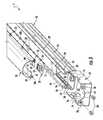
- FIG. 1is a top view showing an embodiment of a LED lamp of the invention.
- FIG. 2is a side view of the LED lamp of FIG. 1 .
- FIG. 3is a partial exploded view of the LED lamp of FIG. 1 .
- FIG. 4is a partial perspective view of the LED lamp of FIG. 1 in a first position.
- FIGS. 5 and 6are perspective views of one embodiment of the top section of the end cap used in the LED lamp of FIG. 1 .
- FIGS. 7 and 8are perspective views of a second embodiment of the top section of the end cap used in the LED lamp of FIG. 1 .
- FIG. 9is a partial perspective section view of the LED lamp of FIG. 1 .
- FIG. 10is a top view showing two LED lamps connected together.
- FIG. 11is a partial perspective section view of the LED lamp of FIG. 1 .
- FIG. 12is a section view of the LED lamp of FIG. 1 .
- FIGS. 13-16are perspective views showing embodiments of a mounting bracket used with the lamp of FIG. 1 .
- FIG. 17is a partial perspective view showing an embodiment of an electrical connector used with the lamp of FIG. 1 .
- FIG. 18is a perspective view of two lamps shown in a partially connected position.
- FIG. 19is a perspective view of two lamps shown in an electrically connected position.
- FIG. 20is a side view showing two LED lamps connected together.
- FIG. 21is a perspective view showing two LED lamps connected together.
- FIG. 22is a perspective view showing two LED lamps connected together in a second embodiment.
- FIGS. 23-27schematically illustrate embodiments of the electrical connections for the lamp.
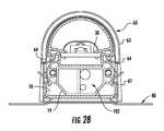
- FIG. 28is a section view of the lamp of FIG. 1 .
- Relative terms such as “below” or “above” or “upper” or “lower” or “horizontal” or “vertical” or “top” or “bottom”may be used herein to describe a relationship of one element, layer or region to another element, layer or region as illustrated in the figures. It will be understood that these terms are intended to encompass different orientations of the device in addition to the orientation depicted in the figures.
- solid state light emitteror “solid state emitter” may include a light emitting diode, laser diode, organic light emitting diode, and/or other semiconductor device which includes one or more semiconductor layers, which may include silicon, silicon carbide, gallium nitride and/or other semiconductor materials, a substrate which may include sapphire, silicon, silicon carbide and/or other microelectronic substrates, and one or more contact layers which may include metal and/or other conductive materials.
- a solid-state lighting deviceproduces light (ultraviolet, visible, or infrared) by exciting electrons across the band gap between a conduction band and a valence band of a semiconductor active (light-emitting) layer, with the electron transition generating light at a wavelength that depends on the band gap.
- the color (wavelength) of the light emitted by a solid-state emitterdepends on the materials of the active layers thereof.
- solid-state light emittersmay have peak wavelengths in the visible range and/or be used in combination with lumiphoric materials having peak wavelengths in the visible range.
- Multiple solid state light emitters and/or multiple lumiphoric materialsmay be used in a single device, such as to produce light perceived as white or near white in character.
- the aggregated output of multiple solid-state light emitters and/or lumiphoric materialsmay generate white light.
- Solid state light emittersmay be used individually or in combination with one or more lumiphoric materials (e.g., phosphors, scintillators, lumiphoric inks) and/or optical elements to generate light at a peak wavelength, or of at least one desired perceived color (including combinations of colors that may be perceived as white).
- lumiphoricalso called ‘luminescent’
- Inclusion of lumiphoric (also called ‘luminescent’) materials in lighting devices as described hereinmay be accomplished by direct coating on solid state light emitter, adding such materials to encapsulants, adding such materials to lenses, by embedding or dispersing such materials within lumiphor support elements, and/or coating such materials on lumiphor support elements.
- Other materialssuch as light scattering elements (e.g., particles) and/or index matching materials, may be associated with a lumiphor, a lumiphor binding medium, or a lumiphor support element that may be spatially segregated from a solid state emitter.
- Linear lightssuch as fluorescent lights may comprise a fluorescent tube releasably mounted in a fixture that may be mounted on a ceiling or other structure.
- One use of linear lightsis as down and/or up lighting in commercial fixtures where the light is mounted in a rack or other merchandise display to illuminate displayed merchandise.
- Such linear lightsmay also be used in non-commercial applications such as a down light mounted under a kitchen cabinet, for example, to provide down lighting on a counter or other surface.
- Linear lightsare used in a variety of applications to provide down lighting, up lighting, and/or accent lighting in a variety of applications.
- Linear lightas used herein means a lamp having an illuminated enclosure that has a significantly longer length than width.
- the linear light of the inventionmay be approximately 1-3 inches in width with a length of between approximately 12-80 inches.
- the LED lamp 1comprises a base 10 .
- the base 10may be made of a thermally conductive material such that it functions as a heat sink to dissipate heat from the LED assembly.
- the base 10may be made of a rigid material to support the LED assembly 30 and lens 50 .
- the base 10may be made of extruded aluminum. While aluminum may be used, other rigid, thermally conductive materials and manufacturing processes may be used to form the base 10 .
- the base 10defines a support surface for the LED assembly 30 that may be comprised of a pair of planar support surfaces such as flanges 12 that support the longitudinal edges of the LED assembly 30 along the length thereof.
- the spaced flanges 12may be used as the support surface in embodiments where the LED assembly 30 comprises a generally rigid substrate that is capable of spanning the flanges 12 and physically supporting the LEDs 32 .
- the flanges 12extend for the length of the LED assembly 30 ; however, the flanges 12 may extend for less than the entire length of the LED assembly provided that they adequately support and retain the LED assembly 30 .
- gapsmay be provided in the flanges 12 while still adequately supporting the LED assembly.
- the flanges 12face one another to create a planar support for receiving and supporting the LED assembly 30 .
- the LED assembly 30may be thermally coupled to the base 10 such that heat generated by the LEDs 32 is transferred to the base 10 via the LED board 34 and is dissipated to the ambient environment by the base 10 .
- the thermal couple between the LED board 34 and base 10may be provided by providing surface to surface contact between the board 34 and the base 10 .
- thermally conductive layersmay be provided between the base 10 and the board 34 .
- thermal adhesivemay be used to attach the board 34 to the base 10 .
- the support surfacemay comprise a planar member that extends across the entire width of the LED assembly rather than two spaced flanges 12 .
- the flanges 12are supported on side walls 14 that extend generally perpendicularly from a bottom wall 16 .
- a cross member 18may be provided between the side walls 14 to provide structural rigidity to the base 10 such that the base 10 does not flex or bend and to define a wire way 101 for containing the lamp electronics 102 , such as the power supply and other electronics, and wiring as shown in FIG. 28 .
- the side walls 14define grooves 20 that extend for the length of, or for a portion of the length of, the base 10 .
- the grooves 20may be engaged by mounting brackets 40 for securing the lamp to a surface.
- Different embodiments of the mounting bracket 40may be used for different mounting applications.
- the mounting bracket 40comprises a base plate 42 that extends for approximately the width of the base 10 .
- At least one engagement member 44extends from each end of the base plate 42 for releasably engaging the side walls 14 of the base 10 such that the lamp may be secured to the bracket 40 .
- the engagement members 44comprise resilient tabs 46 that extend from the base plate 42 and that are shaped and dimensioned to engage the grooves 20 formed on the side walls 14 of base 10 .
- Each tab 46includes a protrusion 48 that is shaped and dimensioned to fit into grooves 20 to mechanically lock the base 10 to the brackets 40 .
- the tabs 46may be resiliently mounted relative to the base plate 42 such that the tabs 46 may flex to releasably engage the base 10 .
- the tabs 46may be arranged in opposed pairs to clamp the base 10 therebetween. While two tabs 46 are shown on each end of the bracket 40 a greater or fewer number of tabs may be used.
- the base plate 40 and tabs 46may be formed of a single piece of deformable, resilient material such as steel where the resiliency of the material is used to create the bias force of the tabs 46 against the base 10 . In other embodiments the tabs may be formed of separate members that are mounted to the base plate at a hinges and that are biased into engagement with the base by separate springs.
- the tabs 46may be formed with flared ends that create angled camming surfaces 49 where the surfaces 49 are oriented such that the base 10 may be centered between and pushed against the camming surfaces 49 to flex the tabs 46 and allow the base 10 to be inserted between the opposing tabs 46 .
- the force on the tabs 46is released, such as when the protrusions 48 on the tabs 46 are aligned with the grooves 20 , the tabs 46 return toward the undeformed position to create a gripping force on the base 10 sufficient to hold the lamp 1 in the brackets 40 .
- the use of elongated grooves 20 and resilient tabs 46allow the brackets 40 to be located at any position along the length of the base 10 .
- the base 10may also be slid relative to the brackets 40 to allow adjustment of the position of the lamp relative to the brackets 40 after the base 10 is mounted in the brackets 40 .
- a plurality of brackets 40may be used to support a lamp depending upon the length and weight of the lamp.
- bracket 40comprises a pair of mounting flanges 50 that comprise apertures 52 for receiving fasteners such as screws that may be used to secure the bracket 40 to a support surface.
- the mounting flanges 50extend from the plate 42 such that apertures 52 are disposed to either side of the lamp 1 where the apertures 52 are accessible when the lamp 1 is mounted in the bracket 40 .
- the mounting apertures 52may comprise various shaped and sized apertures, slots, channels or the like for receiving any type of fastener.
- the flanges 50may comprise mounting mechanisms other than apertures if desired.
- the mounting mechanismsmay comprise male or female engagement members that engage separate female or male brackets that are mounted to the support surface. Other mechanisms such as adhesive, hook and loop fasteners or the like may also be used.
- FIG. 14shows an alternate embodiment for the mounting bracket where the mounting flanges 50 are angled relative to the plate 42 to define a plane that is disposed at an angle relative to the lamp such that when the flanges 50 are mounted on a support surface the base plate 42 and the lamp 1 are mounted at an angle relative to the support surface.
- FIG. 15shows an alternate embodiment for the mounting bracket where the mounting flanges 50 extend from the sides of the base plate 42 rather than from the ends of the base plate such that the mounting flanges 50 are hidden from view after the lamp is mounted on the brackets 40 . In this embodiment the brackets 40 are mounted to the support surface before the lamp 1 is installed in the brackets 40 .
- FIG. 14shows an alternate embodiment for the mounting bracket where the mounting flanges 50 are angled relative to the plate 42 to define a plane that is disposed at an angle relative to the lamp such that when the flanges 50 are mounted on a support surface the base plate 42 and the lamp 1 are mounted at an angle relative to the support surface.
- FIG. 15shows
- FIG 16shows another alternate embodiment for the mounting bracket 40 where the mounting flange 50 extends from the end of the base plate 42 but is disposed at approximately a 90 degree angle relative to the base plate 42 such that the mounting flange 50 extends along one side wall 14 and the lamp is oriented at a 90 degree angle relative to the support surface.
- Other arrangements of the bracketmay also be provided.
- the LED lamp 1comprises an LED assembly 30 that may be supported by and secured to the base 10 .
- the LED assembly 30may comprise a plurality of LEDs or LED packages 32 that are mounted on LED board 34 and that extend the length of, or substantially the length of, the base 20 to create a desired light pattern.
- the LEDs 32may be arranged such that the light pattern extends the length of, or for a substantial portion of the length of, the lamp and is similar in length to a traditional fluorescent bulb. While in one embodiment the LEDs 32 extend in a line for substantially the entire length of the base 10 , the LEDs 32 may be arranged in other patterns and may extend for less than substantially the entire length of the base if desired.
- the LEDsmay be disposed along the edges of the LED board 34 and directed toward the middle of the lamp.
- the LEDsmay be directed into a waveguide.
- the LEDs 32may be mounted on a LED board 34 that provides physical support for the LEDs 32 and provides an electrical path for providing electrical power to the LEDs.
- the electrical pathprovides power to the LEDs and may comprise the power source, board 34 and lamp electronics 102 .
- the board 34comprises an FR4 board.
- FR4 board circuitry 103may be etched into a copper layer of the board where the circuitry comprises a portion of the electrical path to the LEDs 32 .
- the boardmay comprise a MCPCB, lead frame or other suitable mounting substrate for the LEDs.
- the boardmay also comprise a flex circuit.
- the board 34may comprise the electrical circuitry 103 and components that form part of the electrical path to the LEDs 32 .
- the term “electrical path”can be used to refer to the entire electrical path to the LED array, including an intervening power supply disposed between the electrical connection that would otherwise provide power directly to the LEDs and the LED array, or it may be used to refer to the connection between the mains and all the electronics in the lamp, including the power supply. The term may also be used to refer to the connection between the power supply and the LED array.
- the LEDs 32may be provided in a variety of patterns and may include a wide variety of different types and colors of LEDs to produce light in a wide variety of colors and/or light patterns.
- LEDs as disclosed hereinmay include one or more light affecting elements (including light transmissive, light-absorptive, light reflective and/or lumiphoric materials) formed on, over or around at least one solid state light emitter.
- light affecting elementsincluding light transmissive, light-absorptive, light reflective and/or lumiphoric materials
- twenty two LEDsmay be used arranged in-line and having a 2 inch spacing between LEDs.
- the LEDsmay comprise XT-E LEDs manufactured and sold by CREE Inc.
- the LED board 34may comprise a plurality of fixtures electrically interconnected to make LED board 34 .
- each fixtureis 15 W, 1700 Lm, 125 mA @ 120V.
- Other LEDs and/or combinations of LEDsmay be used depending on the desired characteristics of the emitted light.
- the LEDsmay be center mounted with greater side emitting optical profiles such as CREE XPQ LEDs.
- a prismatic lens or parabolic reflectorsmay be used to create a desired light distribution.
- the base 10 and LED assembly 30may be made of, or covered in, a light reflective material, such as MCPET, white optic, reflective film or paint or the like, to reflect light from these components into mixing chamber 51 .
- the entire base 10 and/or board 34may be made of, or covered in, a reflective material or portions of the base and/or board may be made of reflective material.
- portions of the base and/or board that may be exposed to the emitted lightmay be made of, or covered in, a reflective material.
- a lens 50may be connected to the base 10 to cover the LED assembly 30 and create a mixing chamber 51 for the light emitted from the LEDs 32 .
- the lightis mixed in the chamber 51 and is emitted from the lamp through the lens 50 .
- the lens 50may diffuse the light to provide a uniform, diffuse, color mixed light pattern.
- the lens 50may be made of molded plastic or other material and may be provided with a light diffusing layer. In the drawings the lens is shown as transparent to better illustrate the internal components of the lamp; however, in actual use the lens may be diffusive such that it is light transmissive but not necessarily transparent.
- the light diffusing layermay be provided by etching, application of a coating or film, by the translucent or semitransparent material of the lens, by forming an irregular surface pattern during formation of the lens or by other methods.
- the lens 50has a round or circular cross-sectional shape, however, the lens may have other shapes including a flattened circular shape or oval, a faceted shape, a rectilinear, square or rectangular shape or other suitable shape.
- the lens 50extends substantially the length of the base 10 to cover the LEDs 32 .
- the longitudinal edges 50 a , 50 b of the lens 50are provided with inwardly facing lips or projections 52 and 54 that may be received in outwardly facing longitudinal C-channels 56 , 58 formed along the side walls 14 of the base 10 .
- the channels 56 , 58may be formed by a portion of walls 14 and outwardly facing angled members 59 .
- the lens 50 and projections 52 , 54may be formed as one piece such as of molded plastic.
- the base 10may be formed of extruded, stamped or rolled metal where the channels 56 , 58 are formed as one-piece with the base; however, the base may be made as separate components secured together to form the completed base.
- the projections 52 , 54are inserted into the channels 56 , 58 and mechanically engage the members 59 to retain the lens 50 on the base 10 .
- the projections 52 , 54may be slid into the channels 56 , 58 from the end of the base 10 .
- the projections 52 , 54may also be inserted into the channels 56 , 58 by inserting a first projection 52 into one of the channels 56 and deforming the lens to insert the opposite projection 54 into the opposite channel 58 .
- the lens 50may then be released such that the lens elastically returns to its original shape where the projections 52 , 54 are forced into the opposed channels 56 , 58 .
- the lens 50comprises a second set of inwardly facing flanges 55 , 57 that are spaced from the projections 52 , 54 , respectively, to trap the outwardly facing members 59 .
- the flanges 55 , 57are dimensioned such that when the lens 50 is secured to the base 10 the flanges 55 , 57 engage the top surface of the board 34 to clamp the board 34 between the flanges 55 , 57 and the flanges 12 .
- End caps 60may be provided at the opposite ends of the lens 50 and base 10 to close the interior mixing chamber 51 of LED lamp 1 and to support the electrical connectors for connecting the LEDs to a power source.
- the end caps 60 , base 10 and lens 50together define an enclosure that retains the LEDs 32 .
- the enclosureis partially optically transmissive through the lens 50 .
- Each end cap 60comprises an internal chamber 62 defined by a bottom section 61 and a top section 63 dimensioned and shaped to closely receive the base 10 , and lens 50 .
- the bottom section 61is formed with protrusions 76 that engage the grooves 20 formed in the base 10 .
- the bottom section 61may be slid over the base such that the protrusions 76 slide into grooves 20 and the bottom wall 16 of base 10 rests on the bottom wall 65 of end cap 60 .
- the bottom section 61further comprises apertures 78 for receiving fasteners 80 such as screws that engage mating holes 82 formed in the base 10 .
- the top section 63is provided with two deformable locking members 64 that engage the base 10 such that the top section 63 may be removed from the lamp.
- the locking members 64are made of resilient material and have a first end connected to the top section 63 and an engagement member 66 at the free end that engage channels 56 , 58 formed on the base 10 .
- the locking members 64may be deformed by the base 10 as the top section is attached to the bottom section 61 .
- the ends of the locking members 64are formed with angled camming surfaces 65 that are engaged by the camming surfaces 59 as the top section 63 is mounted on the bottom section.
- the locking members 64return to the undeformed locking position such that the engagement members 66 are biased into engagement with the base 10 .
- the engagement of the engagement members 66 with the side walls 14 of the base 10secures the top section 63 of end cap 60 to the base 10 .
- the locking members 64are located in recesses 74 formed in the bottom section 61 to fix the lateral position of the top section 63 relative to the bottom section 61 .
- Other arrangements of snap-fit connectorsmay be used. For example a fewer or greater number of locking members 64 may be used.
- the deformable locking membersmay be formed on the base 10 and apertures or other mating receptacles may be formed on the end caps.
- the locking membersmay comprise rigid members that are biased to the locking position by separate springs. While use of a snap-fit connector provides a simple assembly method that does not require additional tools, assembly steps or fasteners, the top section 63 may be connected to the bottom section 61 using other connection mechanisms such as separate fasteners, or the like.
- the end wall 83 of the top section 63defines an aperture 92 for receiving an electrical connector of the lamp.
- the top section 63is formed with a slotted aperture 94 for receiving the internal wiring of the lamp such that an electrical connector may be extended to the outside of the lamp with the wiring to the connector passing through the slot 94 .
- the top section 63 acomprises an aperture 92 where the aperture is round aperture 96 formed in end wall 83 that receives a cable 98 that connects to the electrical path of the lamp (See, for example, FIG. 17 ). The cable 98 may be held in a strain relief collar or grommet 100 secured in the aperture 96 .
- the choice of top section 63 , 63 ais selected based on the type of connector used to connect to the electronics of the lamp as will be described.
- the lamp of the inventionmay be used as part of a modular system allowing multiple lamps to be connected together to create a linear light of varying length.
- the lamphas a length and a diameter suitable for use as a replacement for existing linear lights such as fluorescent tubes.
- the lampmay have a length of approximately 48 inches that is sized to replace a 48 inch light fixture. While a specific length has been described it will be appreciated that the lamp may be made in any suitable length including standard and non-standard lengths.
- the lampmay be made in a one foot length, a two foot length, a three foot length or other lengths including significantly longer lengths.
- a single installationmay use lamps of varying lengths.
- lamp 1may comprise a power cable 98 that extends from the exterior of the lamp through aperture 96 in the end cap 60 and into the wire way 101 formed in base 10 between bottom wall 16 and cross member 18 .
- the power cable 98may contain wires for providing both sides of the current and a ground wire.
- the power cable 98is connected to lamp electronics 102 that may be located in the wire way 101 .
- the lamp electronics 102are contained in the wire way 102 and may comprise a board or boards, such as a circuit board, on which the power supply and other electrical components are mounted.
- the power cable 98is electrically coupled to the lamp electronics 102 for carrying both sides of the critical current to the lamp.
- the power cable 98may terminate in a plug or other connector 104 that may be inserted into a mating outlet that is connected to a power source 99 .
- the connector 104may comprise a hard wire connection to power source 99 .
- the power cable 98forms a part of the electrical path for powering the LEDs.
- the electrical pathmay also include the lamp electronics 102 , conductors 105 from the lamp electronics 102 to the LED board 34 and conductors 103 on the LED board to the LEDs 32 .
- one lampmay have the driver and the appropriate current is supplied to all of the LEDs in all of the Lamps from the lamp with the driver while in other embodiment each lamp may comprise a driver such that each lamp receives the same power from the power source.
- the electrical current from power cable 98is also provided to an electrical connector 110 via wires 112 .
- the electrical pathmay also include electrical connector 110 and wires 112 .
- the electrical currentmay be provided through the lamp electronics 102 where the lamp electronics and wiring 112 are connected in series (shown in FIG. 23 ) or the current may be provided to connector 110 in parallel with the lamp electronics 102 where power cable 98 is electrically coupled to wires 112 (shown in FIG. 27 ).
- Connector 110is located in compartment 115 in base 10 underneath the top section 63 of end cap 60 where it may be stored out of sight when not in use.
- Connector 110may comprise one of a male or female electrical plug configured to mate with a connector 114 that comprises a corresponding female or male plug on a second lamp 1 a to complete an electrical path between the plugs.
- the second connector 114is connected to the lamp electronics 102 of the second lamp 1 a by wiring such that electrical current provided from the first lamp may be used to power the second lamp via the coupling of electrical connectors 110 , 114 ( FIG. 24 ).
- Connector 110may be provided with a releasable locking member 111 that engages mating locking member 113 on connector 114 .
- the top section 63 of end cap 60is removed on both lamps 1 and 1 a to reveal connectors 110 and 114 .
- the top sections 63are removed by flexing locking members 64 to disengage the locking members from the base.
- the connector 110is extended to the exterior of lamp 1 and is electrically coupled to connector 114 in compartment 115 of lamp 1 a .
- Wires 112are made of a sufficient length to allow the connector 110 to extend outside of the end cap 60 .
- the top sections 63are mounted on the bottom sections 61 of both lamps 1 and 1 a .
- the top sections 63are mounted by forcing the locking members 64 over angled camming surfaces 59 such that the locking members 64 deform and engage channels 56 and 58 on the base 10 .
- the wiring 112is extended through slots 94 such that the wiring extends between the lamps 1 and 1 a and the connectors 110 , 112 are located in the end cap of one of lamps 1 and 1 a .
- the second lamp 1 ais connected to the first lamp 1 such that current may be delivered from lamp 1 to lamp 1 a .
- the lamps 1 and 1 aare intended to be mounted in an end to end abutting relationship where the lamps are arranged in a linear path.
- the wires 112are covered by the end caps because the walls 83 of the end caps 60 of the adjacent lamps 1 and 1 a abut or are closely adjacent to one another. “Abut” as used herein means that the end caps are physically touching or are in very close proximity to one another such that the wires 112 extending between the lamps 1 and 1 a are not exposed or accessible.
- the second lamp 1 amay be provided with a first connector 110 at its opposite end such that the second lamp 1 a may be connected to a third lamp as described above such that current is carried from the first lamp to the second lamp and from the second lamp to a third lamp or additional lamps.
- This arrangementmay be repeated for a plurality of lamps to create a modular, expandable linear lighting system.
- Different lampsmay be provided with the different types of connectors as needed to complete the system.
- one lampmay be provided with a first connector 104 and power cable 98 for connecting to a source of power 99 and a first connector 110 for connecting to additional lamps ( FIG. 23 ).
- Intermediate lampsmay comprise one of the first connector 110 and the second connector 114 ( FIG. 24 ) such that these lamps may be connected in series with one another.
- a third configuration of the lampmay be provided only with a first connector 110 ( FIG. 26 ) for connecting to one lamp such that this lamp functions as the end lamp in a series of interconnected lamps.
- one lampmay be provided with a first connector 104 and power cable 98 ( FIG. 25 ) where this lamp connects to a source of power but is not intended to be connected to another lamp.
- all of the lampsmay include at least two connectors. The various mechanisms for making the electrical connections to and from the lamps may be used in various combinations.
- a bracket 120may be used to mechanically connect adjacent lamps together.
- the bracket 120may have a construction similar to the mounting brackets 40 where a base plate 122 is dimensioned to span two lamps 1 , 1 a .
- the base plate 122is dimensioned to extend across and beyond the two abutting end caps.
- a pair of tabs 124is provided on each side of the base plate 122 , the tabs 124 being positioned to engage the grooves 20 in the base 10 , as previously described with respect to tabs 44 , just beyond the internal edges of the end caps 60 .
- the two end caps 60are trapped between the tabs 124 such that the lamps 1 , 1 a may not be separated from one another without removing the bracket 120 .
- the first connector 110may be mounted at the end of a flexible electrical connector 130 having a sufficient length such that the connected lamps 1 , 1 a may be spaced from one another such that the lamps are not abutting.
- the lamps 1 and 1 amay be oriented relative to one another in other than a straight line by flexing connector 130 .
- the flexible connector 130may comprise wires 112 having a connector 110 , 114 at the end thereof where the wires extend a distance from one of the lamps 1 , 1 a that allow the wires to flex to allow the lamps 1 , 1 a to be oriented at any angle relative to one another. It may be desirable or required to encase the wires 112 such as by using an electrically insulated cable 132 because the electrical wires 112 would otherwise be exposed to the ambient environment. Other insulating devices such as conduit, flexible metal cables or the like may also be used to encase the wiring. As used herein “cable” means a flexible electrical connection that may be exposed to the ambient environment and that allows two interconnected lamps to be oriented at angles relative to one another by flexing the cable.
- a second end cap top section 63 amay be used that has an aperture 96 large enough to receive the cable.
- a strain relief grommet 100may be used to line the aperture.
- an LED board 34is populated with LEDs 32 .
- the LED board 34is located on the flanges 12 of the base 10 such that the board 34 is supported by the base 10 .
- the base 10may also function as a heat sink to dissipate heat generated by the LEDs 32 to the ambient environment.
- the lamp electronics 102are located in wireway 101 and the electrical path 105 from the board 34 to the power supply 102 is completed.
- the appropriate electrical connectors 104 , 110 , 114are connected to the electrical path using wires 114 and/or power cable 98 .
- the lens 50is mounted to the base 10 by inserting the flanges 52 , 54 of the lens into the mating C-channels 56 , 58 on the base 10 .
- the flangesmay be slid into the C-channels or the lens may be deformed and snap-fit into the C-channels.
- the flanges 55 , 57 of the lens 50are engaged with the board 34 to hold the LED board 34 against the flanges 12 .
- the first and second end caps 60may be mounted to the base 10 with the electrical connectors contained in the end caps as previously described. Plural lamps may be connected together to create a lighting system during installation of the lamps on site.
Landscapes
- Engineering & Computer Science (AREA)
- General Engineering & Computer Science (AREA)
- Non-Portable Lighting Devices Or Systems Thereof (AREA)
- Arrangement Of Elements, Cooling, Sealing, Or The Like Of Lighting Devices (AREA)
- Fastening Of Light Sources Or Lamp Holders (AREA)
Abstract
Description
Claims (20)
Priority Applications (1)
| Application Number | Priority Date | Filing Date | Title |
|---|---|---|---|
| US14/103,063US9423116B2 (en) | 2013-12-11 | 2013-12-11 | LED lamp and modular lighting system |
Applications Claiming Priority (1)
| Application Number | Priority Date | Filing Date | Title |
|---|---|---|---|
| US14/103,063US9423116B2 (en) | 2013-12-11 | 2013-12-11 | LED lamp and modular lighting system |
Publications (2)
| Publication Number | Publication Date |
|---|---|
| US20150159848A1 US20150159848A1 (en) | 2015-06-11 |
| US9423116B2true US9423116B2 (en) | 2016-08-23 |
Family
ID=53270758
Family Applications (1)
| Application Number | Title | Priority Date | Filing Date |
|---|---|---|---|
| US14/103,063Active2034-07-18US9423116B2 (en) | 2013-12-11 | 2013-12-11 | LED lamp and modular lighting system |
Country Status (1)
| Country | Link |
|---|---|
| US (1) | US9423116B2 (en) |
Cited By (9)
| Publication number | Priority date | Publication date | Assignee | Title |
|---|---|---|---|---|
| US20160327237A1 (en)* | 2015-05-07 | 2016-11-10 | Abl Ip Holding Llc | Luminaire with pre-assembled light engine and lens |
| US20180080637A1 (en)* | 2016-09-20 | 2018-03-22 | Osram Gmbh | Lighting device and corresponding fixing system |
| US20180292074A1 (en)* | 2014-05-30 | 2018-10-11 | Oelo Llc | Lighting system and method of use |
| US10168012B1 (en)* | 2018-05-04 | 2019-01-01 | MaxLite, Inc. | Modular vapor-tight light fixture |
| US20220120414A1 (en)* | 2019-12-02 | 2022-04-21 | Opple Lighting Co., Ltd. | Luminaire |
| US11454381B1 (en)* | 2021-04-30 | 2022-09-27 | Lmpg Inc. | Luminaire connection systems |
| US20230228389A1 (en)* | 2022-01-19 | 2023-07-20 | Jie Li | Multidirectional splicing lighting atmosphere illumination module and modular illumination device thereof |
| US20250102135A1 (en)* | 2023-09-20 | 2025-03-27 | John Dasilva | LED Shop Light |
| EP4624798A1 (en)* | 2024-03-27 | 2025-10-01 | Genuit S.r.l. | Cable duct |
Families Citing this family (18)
| Publication number | Priority date | Publication date | Assignee | Title |
|---|---|---|---|---|
| EP2910850A1 (en)* | 2014-02-21 | 2015-08-26 | A.A.G. Stucchi S.r.l. | Supporting device for LEDs, particularly for LED modules |
| CA2919802C (en)* | 2015-02-04 | 2019-02-26 | Stephen Barry Mccane | Easy install light engine retrofit kit and method for using same |
| CN204420904U (en)* | 2015-03-13 | 2015-06-24 | 合肥京东方显示光源有限公司 | A kind of light bar fixing device and be provided with the backlight of this light bar fixing device |
| JP6575900B2 (en)* | 2015-07-06 | 2019-09-18 | パナソニックIpマネジメント株式会社 | Light source unit and lighting fixture |
| DE102016015924B3 (en)* | 2015-12-09 | 2020-09-24 | Ibv Holding Gmbh | Luminaire for a modular lighting system, modular lighting system and connector |
| DE102015122566A1 (en)* | 2015-12-22 | 2017-06-22 | Rehau Ag + Co | Lighting system comprising several light units |
| DE102015122510A1 (en)* | 2015-12-22 | 2017-06-22 | Rehau Ag + Co | Lighting device with an elongated lamp and a protective element made of a plastic material |
| US9802308B2 (en)* | 2016-02-12 | 2017-10-31 | Jeremiah Coutts | Rail lighting and lamp attachment for automotive creeper |
| US10240759B2 (en)* | 2016-03-18 | 2019-03-26 | MaxLite, Inc. | Modular lighting fixture |
| US20190178486A1 (en)* | 2017-12-13 | 2019-06-13 | Wei Chen | Module for led lighting fixture |
| US10980187B2 (en) | 2019-02-21 | 2021-04-20 | Omachron Intellectual Property Inc. | Lighting system for indoor cultivation facility |
| CN209370988U (en)* | 2019-03-15 | 2019-09-10 | 欧普照明股份有限公司 | Cabinet lamp and lamp cabinet |
| WO2021108406A1 (en)* | 2019-11-25 | 2021-06-03 | Molex, Llc | Led lighting fixture with interconnect |
| US11493179B1 (en)* | 2021-11-15 | 2022-11-08 | Diem Gmbh | Linear luminaire including a light inset inserted in a channel |
| US11852309B2 (en) | 2021-11-15 | 2023-12-26 | Diem Gmbh | Linear luminaire including a light inset inserted in a channel |
| US12345399B2 (en)* | 2022-11-15 | 2025-07-01 | AQ Lighting Texas, Inc. | Pluggable low voltage outdoor watertight lighting system for path lighting |
| US11969875B1 (en)* | 2023-06-30 | 2024-04-30 | John Gess | Mechanic's creeper |
| EP4610559A1 (en)* | 2024-03-01 | 2025-09-03 | ZG Lighting SRB d. o. o. | Longitudinal luminaire with end caps |
Citations (65)
| Publication number | Priority date | Publication date | Assignee | Title |
|---|---|---|---|---|
| US5463280A (en) | 1994-03-03 | 1995-10-31 | National Service Industries, Inc. | Light emitting diode retrofit lamp |
| JPH08162677A (en) | 1994-12-05 | 1996-06-21 | Nireco Corp | Elongated light source using light emitting diode |
| US5585783A (en) | 1994-06-28 | 1996-12-17 | Hall; Roger E. | Marker light utilizing light emitting diodes disposed on a flexible circuit board |
| US5655830A (en) | 1993-12-01 | 1997-08-12 | General Signal Corporation | Lighting device |
| JPH09265807A (en) | 1996-03-29 | 1997-10-07 | Toshiba Lighting & Technol Corp | LED light source, LED signal light and traffic light |
| US5688042A (en) | 1995-11-17 | 1997-11-18 | Lumacell, Inc. | LED lamp |
| WO1998033007A1 (en) | 1997-01-23 | 1998-07-30 | Koninklijke Philips Electronics N.V. | Luminaire |
| US5949347A (en) | 1996-09-11 | 1999-09-07 | Leotek Electronics Corporation | Light emitting diode retrofitting lamps for illuminated signs |
| US5947588A (en) | 1997-10-06 | 1999-09-07 | Grand General Accessories Manufacturing Inc. | Light fixture with an LED light bulb having a conventional connection post |
| US5952916A (en) | 1998-05-28 | 1999-09-14 | Atras Auto Co., Ltd | Hammer-equipped emergency signal device |
| JP2000173304A (en) | 1998-11-30 | 2000-06-23 | Toshiba Lighting & Technology Corp | Aviation sign light |
| GB2345954A (en) | 1999-01-20 | 2000-07-26 | Ian Lennox Crawford | Light bulb with a plastic bulb mounting portion and LED light source. |
| EP1058221A2 (en) | 1999-06-03 | 2000-12-06 | Leotek Electronics Corporation | Method and apparatus for retro-fitting a traffic signal light with a light-emitting diode lamp module |
| WO2001024583A1 (en) | 1999-09-29 | 2001-04-05 | Transportation And Environment Research Institute Ltd. | Light emitting diode (led) lamp |
| US6220722B1 (en) | 1998-09-17 | 2001-04-24 | U.S. Philips Corporation | Led lamp |
| JP2001118403A (en) | 1999-10-18 | 2001-04-27 | Tokiwa Dengyo Kk | Light-emitting body and signal lamp |
| WO2001060119A2 (en) | 2000-02-11 | 2001-08-16 | Gerhard Abler | Lighting body |
| US6276822B1 (en) | 1998-02-20 | 2001-08-21 | Yerchanik Bedrosian | Method of replacing a conventional vehicle light bulb with a light-emitting diode array |
| US20020060526A1 (en) | 2000-02-11 | 2002-05-23 | Jos Timmermans | Light tube and power supply circuit |
| US6452217B1 (en) | 2000-06-30 | 2002-09-17 | General Electric Company | High power LED lamp structure using phase change cooling enhancements for LED lighting products |
| US6465961B1 (en) | 2001-08-24 | 2002-10-15 | Cao Group, Inc. | Semiconductor light source using a heat sink with a plurality of panels |
| US6585393B1 (en)* | 1998-10-09 | 2003-07-01 | Satco Products, Inc. | Modular accent light fixture |
| US6634770B2 (en) | 2001-08-24 | 2003-10-21 | Densen Cao | Light source using semiconductor devices mounted on a heat sink |
| US6635987B1 (en) | 2000-09-26 | 2003-10-21 | General Electric Company | High power white LED lamp structure using unique phosphor application for LED lighting products |
| US6639360B2 (en) | 2001-01-31 | 2003-10-28 | Gentex Corporation | High power radiation emitter device and heat dissipating package for electronic components |
| US6746885B2 (en) | 2001-08-24 | 2004-06-08 | Densen Cao | Method for making a semiconductor light source |
| US20040201990A1 (en) | 2003-04-10 | 2004-10-14 | Meyer William E. | LED lamp |
| EP1475846A2 (en) | 2003-05-06 | 2004-11-10 | Seiko Epson Corporation | Light emitting diode based light source with cooling liquid arrangement, and projection-type display apparatus |
| WO2004100213A2 (en) | 2003-05-05 | 2004-11-18 | Gelcore Llc | Led-based light bulb |
| US6853151B2 (en) | 2002-11-19 | 2005-02-08 | Denovo Lighting, Llc | LED retrofit lamp |
| US6860628B2 (en) | 2002-07-17 | 2005-03-01 | Jonas J. Robertson | LED replacement for fluorescent lighting |
| US6936968B2 (en) | 2001-11-30 | 2005-08-30 | Mule Lighting, Inc. | Retrofit light emitting diode tube |
| US7048410B2 (en) | 2004-02-25 | 2006-05-23 | Murray Kutler | Support and enclosure structure for fluorescent light bulbs |
| US7307391B2 (en) | 2006-02-09 | 2007-12-11 | Led Smart Inc. | LED lighting system |
| US20090140271A1 (en) | 2007-11-30 | 2009-06-04 | Wen-Jyh Sah | Light emitting unit |
| US20090184618A1 (en) | 2008-01-18 | 2009-07-23 | Sanyo Electric Co., Ltd. | Light-emitting device and lighting apparatus incorporating same |
| CN101655189A (en) | 2009-07-16 | 2010-02-24 | 艾迪光电(杭州)有限公司 | Hollow liquid cooling LED bar-shaped lamp |
| US20100214779A1 (en)* | 2009-02-23 | 2010-08-26 | Ying-Feng Kao | LED Fluorescent Tube |
| WO2010099755A1 (en) | 2009-03-06 | 2010-09-10 | 深圳北森科技有限公司 | Led fluorescent lamp |
| US7815338B2 (en) | 2008-03-02 | 2010-10-19 | Altair Engineering, Inc. | LED lighting unit including elongated heat sink and elongated lens |
| US20100277098A1 (en)* | 2009-04-30 | 2010-11-04 | Timothy Sarna | Led lighting system |
| US7926975B2 (en) | 2007-12-21 | 2011-04-19 | Altair Engineering, Inc. | Light distribution using a light emitting diode assembly |
| US7976196B2 (en) | 2008-07-09 | 2011-07-12 | Altair Engineering, Inc. | Method of forming LED-based light and resulting LED-based light |
| US8058659B2 (en) | 2008-08-26 | 2011-11-15 | Albeo Technologies, Inc. | LED chip-based lighting products and methods of building |
| US8093823B1 (en) | 2000-02-11 | 2012-01-10 | Altair Engineering, Inc. | Light sources incorporating light emitting diodes |
| WO2012011279A1 (en) | 2010-07-20 | 2012-01-26 | パナソニック株式会社 | Lightbulb shaped lamp |
| US8115411B2 (en) | 2006-02-09 | 2012-02-14 | Led Smart, Inc. | LED lighting system |
| US20120040585A1 (en) | 2010-08-10 | 2012-02-16 | David Huang | Method of Assembling An Airtight LED Light Bulb |
| US8118447B2 (en) | 2007-12-20 | 2012-02-21 | Altair Engineering, Inc. | LED lighting apparatus with swivel connection |
| US20120044689A1 (en)* | 2009-04-30 | 2012-02-23 | Osram Ag | Lighting system comprising at least one luminous band |
| US20120051041A1 (en) | 2010-08-31 | 2012-03-01 | Cree, Inc. | Troffer-Style Fixture |
| WO2012031533A1 (en) | 2010-09-08 | 2012-03-15 | 浙江锐迪生光电有限公司 | Led lamp bulb and led lighting bar capable of emitting light over 4π |
| US8231245B2 (en)* | 2009-02-13 | 2012-07-31 | Dialight Corporation | LED lighting fixture |
| US8324817B2 (en) | 2008-10-24 | 2012-12-04 | Ilumisys, Inc. | Light and light sensor |
| US8360599B2 (en)* | 2008-05-23 | 2013-01-29 | Ilumisys, Inc. | Electric shock resistant L.E.D. based light |
| US8362710B2 (en) | 2009-01-21 | 2013-01-29 | Ilumisys, Inc. | Direct AC-to-DC converter for passive component minimization and universal operation of LED arrays |
| US8421366B2 (en) | 2009-06-23 | 2013-04-16 | Ilumisys, Inc. | Illumination device including LEDs and a switching power control system |
| US8419223B2 (en)* | 2009-04-23 | 2013-04-16 | Billy V. Withers | LED tube to replace fluorescent tube |
| US8449137B2 (en) | 2009-06-24 | 2013-05-28 | Elumigen Llc | Solid state tube light assembly |
| US8596813B2 (en) | 2010-07-12 | 2013-12-03 | Ilumisys, Inc. | Circuit board mount for LED light tube |
| US20140036505A1 (en)* | 2012-07-31 | 2014-02-06 | Bartco Lighting, Inc. | LED Lighting System |
| US20140043804A1 (en) | 2010-12-08 | 2014-02-13 | Cree, Inc. | Linear led lamp |
| US8746933B2 (en)* | 2010-10-19 | 2014-06-10 | Feelux Co., Ltd. | Lighting apparatus |
| US9004716B2 (en)* | 2012-09-07 | 2015-04-14 | High Perfection Technology Co., Ltd. | LED tube socket, adaptor and assembly thereof |
| US9115858B2 (en)* | 2013-05-09 | 2015-08-25 | Inspired LED, LLC | Extended length flexible LED light strip system |
- 2013
- 2013-12-11USUS14/103,063patent/US9423116B2/enactiveActive
Patent Citations (73)
| Publication number | Priority date | Publication date | Assignee | Title |
|---|---|---|---|---|
| US5655830A (en) | 1993-12-01 | 1997-08-12 | General Signal Corporation | Lighting device |
| US5463280A (en) | 1994-03-03 | 1995-10-31 | National Service Industries, Inc. | Light emitting diode retrofit lamp |
| US5585783A (en) | 1994-06-28 | 1996-12-17 | Hall; Roger E. | Marker light utilizing light emitting diodes disposed on a flexible circuit board |
| JPH08162677A (en) | 1994-12-05 | 1996-06-21 | Nireco Corp | Elongated light source using light emitting diode |
| US5688042A (en) | 1995-11-17 | 1997-11-18 | Lumacell, Inc. | LED lamp |
| JPH09265807A (en) | 1996-03-29 | 1997-10-07 | Toshiba Lighting & Technol Corp | LED light source, LED signal light and traffic light |
| US5949347A (en) | 1996-09-11 | 1999-09-07 | Leotek Electronics Corporation | Light emitting diode retrofitting lamps for illuminated signs |
| WO1998033007A1 (en) | 1997-01-23 | 1998-07-30 | Koninklijke Philips Electronics N.V. | Luminaire |
| US5947588A (en) | 1997-10-06 | 1999-09-07 | Grand General Accessories Manufacturing Inc. | Light fixture with an LED light bulb having a conventional connection post |
| US6276822B1 (en) | 1998-02-20 | 2001-08-21 | Yerchanik Bedrosian | Method of replacing a conventional vehicle light bulb with a light-emitting diode array |
| US5952916A (en) | 1998-05-28 | 1999-09-14 | Atras Auto Co., Ltd | Hammer-equipped emergency signal device |
| US6220722B1 (en) | 1998-09-17 | 2001-04-24 | U.S. Philips Corporation | Led lamp |
| US6585393B1 (en)* | 1998-10-09 | 2003-07-01 | Satco Products, Inc. | Modular accent light fixture |
| JP2000173304A (en) | 1998-11-30 | 2000-06-23 | Toshiba Lighting & Technology Corp | Aviation sign light |
| GB2345954A (en) | 1999-01-20 | 2000-07-26 | Ian Lennox Crawford | Light bulb with a plastic bulb mounting portion and LED light source. |
| EP1058221A2 (en) | 1999-06-03 | 2000-12-06 | Leotek Electronics Corporation | Method and apparatus for retro-fitting a traffic signal light with a light-emitting diode lamp module |
| WO2001024583A1 (en) | 1999-09-29 | 2001-04-05 | Transportation And Environment Research Institute Ltd. | Light emitting diode (led) lamp |
| JP2001118403A (en) | 1999-10-18 | 2001-04-27 | Tokiwa Dengyo Kk | Light-emitting body and signal lamp |
| US8093823B1 (en) | 2000-02-11 | 2012-01-10 | Altair Engineering, Inc. | Light sources incorporating light emitting diodes |
| US20020060526A1 (en) | 2000-02-11 | 2002-05-23 | Jos Timmermans | Light tube and power supply circuit |
| WO2001060119A2 (en) | 2000-02-11 | 2001-08-16 | Gerhard Abler | Lighting body |
| US8247985B2 (en) | 2000-02-11 | 2012-08-21 | Ilumisys, Inc. | Light tube and power supply circuit |
| US8382327B2 (en) | 2000-02-11 | 2013-02-26 | Ilumisys, Inc. | Light tube and power supply circuit |
| US8482212B1 (en) | 2000-02-11 | 2013-07-09 | Ilumisys, Inc. | Light sources incorporating light emitting diodes |
| US7510299B2 (en) | 2000-02-11 | 2009-03-31 | Altair Engineering, Inc. | LED lighting device for replacing fluorescent tubes |
| US7049761B2 (en) | 2000-02-11 | 2006-05-23 | Altair Engineering, Inc. | Light tube and power supply circuit |
| US6452217B1 (en) | 2000-06-30 | 2002-09-17 | General Electric Company | High power LED lamp structure using phase change cooling enhancements for LED lighting products |
| US6635987B1 (en) | 2000-09-26 | 2003-10-21 | General Electric Company | High power white LED lamp structure using unique phosphor application for LED lighting products |
| US6639360B2 (en) | 2001-01-31 | 2003-10-28 | Gentex Corporation | High power radiation emitter device and heat dissipating package for electronic components |
| US6465961B1 (en) | 2001-08-24 | 2002-10-15 | Cao Group, Inc. | Semiconductor light source using a heat sink with a plurality of panels |
| US6746885B2 (en) | 2001-08-24 | 2004-06-08 | Densen Cao | Method for making a semiconductor light source |
| US6634770B2 (en) | 2001-08-24 | 2003-10-21 | Densen Cao | Light source using semiconductor devices mounted on a heat sink |
| US6936968B2 (en) | 2001-11-30 | 2005-08-30 | Mule Lighting, Inc. | Retrofit light emitting diode tube |
| US6860628B2 (en) | 2002-07-17 | 2005-03-01 | Jonas J. Robertson | LED replacement for fluorescent lighting |
| US7114830B2 (en) | 2002-07-17 | 2006-10-03 | Plastic Inventions And Patents, Inc. | LED replacement for fluorescent lighting |
| US6853151B2 (en) | 2002-11-19 | 2005-02-08 | Denovo Lighting, Llc | LED retrofit lamp |
| US20040201990A1 (en) | 2003-04-10 | 2004-10-14 | Meyer William E. | LED lamp |
| WO2004100213A2 (en) | 2003-05-05 | 2004-11-18 | Gelcore Llc | Led-based light bulb |
| EP1475846A2 (en) | 2003-05-06 | 2004-11-10 | Seiko Epson Corporation | Light emitting diode based light source with cooling liquid arrangement, and projection-type display apparatus |
| US7048410B2 (en) | 2004-02-25 | 2006-05-23 | Murray Kutler | Support and enclosure structure for fluorescent light bulbs |
| US7307391B2 (en) | 2006-02-09 | 2007-12-11 | Led Smart Inc. | LED lighting system |
| US8115411B2 (en) | 2006-02-09 | 2012-02-14 | Led Smart, Inc. | LED lighting system |
| US20090140271A1 (en) | 2007-11-30 | 2009-06-04 | Wen-Jyh Sah | Light emitting unit |
| US8118447B2 (en) | 2007-12-20 | 2012-02-21 | Altair Engineering, Inc. | LED lighting apparatus with swivel connection |
| US7926975B2 (en) | 2007-12-21 | 2011-04-19 | Altair Engineering, Inc. | Light distribution using a light emitting diode assembly |
| US20090184618A1 (en) | 2008-01-18 | 2009-07-23 | Sanyo Electric Co., Ltd. | Light-emitting device and lighting apparatus incorporating same |
| US7815338B2 (en) | 2008-03-02 | 2010-10-19 | Altair Engineering, Inc. | LED lighting unit including elongated heat sink and elongated lens |
| US8360599B2 (en)* | 2008-05-23 | 2013-01-29 | Ilumisys, Inc. | Electric shock resistant L.E.D. based light |
| US7976196B2 (en) | 2008-07-09 | 2011-07-12 | Altair Engineering, Inc. | Method of forming LED-based light and resulting LED-based light |
| US8282247B2 (en) | 2008-07-09 | 2012-10-09 | Ilumisys, Inc. | Method of forming LED-based light and resulting LED-based light |
| US8573813B2 (en) | 2008-07-09 | 2013-11-05 | Ilumisys, Inc. | LED-based light with supported heat sink |
| US8058659B2 (en) | 2008-08-26 | 2011-11-15 | Albeo Technologies, Inc. | LED chip-based lighting products and methods of building |
| US8324817B2 (en) | 2008-10-24 | 2012-12-04 | Ilumisys, Inc. | Light and light sensor |
| US8362710B2 (en) | 2009-01-21 | 2013-01-29 | Ilumisys, Inc. | Direct AC-to-DC converter for passive component minimization and universal operation of LED arrays |
| US8231245B2 (en)* | 2009-02-13 | 2012-07-31 | Dialight Corporation | LED lighting fixture |
| US20100214779A1 (en)* | 2009-02-23 | 2010-08-26 | Ying-Feng Kao | LED Fluorescent Tube |
| WO2010099755A1 (en) | 2009-03-06 | 2010-09-10 | 深圳北森科技有限公司 | Led fluorescent lamp |
| US8419223B2 (en)* | 2009-04-23 | 2013-04-16 | Billy V. Withers | LED tube to replace fluorescent tube |
| US20100277098A1 (en)* | 2009-04-30 | 2010-11-04 | Timothy Sarna | Led lighting system |
| US20120044689A1 (en)* | 2009-04-30 | 2012-02-23 | Osram Ag | Lighting system comprising at least one luminous band |
| US8421366B2 (en) | 2009-06-23 | 2013-04-16 | Ilumisys, Inc. | Illumination device including LEDs and a switching power control system |
| US8449137B2 (en) | 2009-06-24 | 2013-05-28 | Elumigen Llc | Solid state tube light assembly |
| CN101655189A (en) | 2009-07-16 | 2010-02-24 | 艾迪光电(杭州)有限公司 | Hollow liquid cooling LED bar-shaped lamp |
| US8596813B2 (en) | 2010-07-12 | 2013-12-03 | Ilumisys, Inc. | Circuit board mount for LED light tube |
| WO2012011279A1 (en) | 2010-07-20 | 2012-01-26 | パナソニック株式会社 | Lightbulb shaped lamp |
| US20120040585A1 (en) | 2010-08-10 | 2012-02-16 | David Huang | Method of Assembling An Airtight LED Light Bulb |
| US20120051041A1 (en) | 2010-08-31 | 2012-03-01 | Cree, Inc. | Troffer-Style Fixture |
| WO2012031533A1 (en) | 2010-09-08 | 2012-03-15 | 浙江锐迪生光电有限公司 | Led lamp bulb and led lighting bar capable of emitting light over 4π |
| US8746933B2 (en)* | 2010-10-19 | 2014-06-10 | Feelux Co., Ltd. | Lighting apparatus |
| US20140043804A1 (en) | 2010-12-08 | 2014-02-13 | Cree, Inc. | Linear led lamp |
| US20140036505A1 (en)* | 2012-07-31 | 2014-02-06 | Bartco Lighting, Inc. | LED Lighting System |
| US9004716B2 (en)* | 2012-09-07 | 2015-04-14 | High Perfection Technology Co., Ltd. | LED tube socket, adaptor and assembly thereof |
| US9115858B2 (en)* | 2013-05-09 | 2015-08-25 | Inspired LED, LLC | Extended length flexible LED light strip system |
Non-Patent Citations (8)
| Title |
|---|
| Cree, Inc., International Application No. PCT/US2011/062795, International Search Report and Written Opinion, Jun. 1, 2012. |
| LiquiLEDs, Liquid LED, http://www.liquidleds.com.tw/, Sep. 28, 2010, 1 page. |
| U.S. Appl. No. 13/772,436, filed Feb. 21, 2013. |
| U.S. Appl. No. 13/943,152, filed Jul. 16, 2013. |
| U.S. Appl. No. 13/943,376, filed Jul. 16, 2013. |
| U.S. Appl. No. 13/943,455, filed Jul. 16, 2013. |
| U.S. Appl. No. 14/224,501, filed Mar. 25, 2014. |
| U.S. Appl. No. 29/467,949, filed Sep. 25, 2013. |
Cited By (16)
| Publication number | Priority date | Publication date | Assignee | Title |
|---|---|---|---|---|
| US10746386B2 (en)* | 2014-05-30 | 2020-08-18 | Oelo Llc | Lighting system and method of use |
| US20180292074A1 (en)* | 2014-05-30 | 2018-10-11 | Oelo Llc | Lighting system and method of use |
| US10371363B2 (en)* | 2014-05-30 | 2019-08-06 | Oelo, LLC | Lighting system and method of use |
| US20160327237A1 (en)* | 2015-05-07 | 2016-11-10 | Abl Ip Holding Llc | Luminaire with pre-assembled light engine and lens |
| US10344945B2 (en)* | 2015-05-07 | 2019-07-09 | Abl Ip Holding Llc | Luminaire with pre-assembled light engine and lens |
| US20180080637A1 (en)* | 2016-09-20 | 2018-03-22 | Osram Gmbh | Lighting device and corresponding fixing system |
| US10451254B2 (en)* | 2016-09-20 | 2019-10-22 | Osram Gmbh | Lighting device and corresponding fixing system |
| US10794554B2 (en) | 2018-05-04 | 2020-10-06 | MaxLite, Inc. | Modular vapor-tight light fixture |
| US10168012B1 (en)* | 2018-05-04 | 2019-01-01 | MaxLite, Inc. | Modular vapor-tight light fixture |
| US11125403B2 (en) | 2018-05-04 | 2021-09-21 | MaxLite, Inc. | Modular vapor-tight light fixture |
| US20220120414A1 (en)* | 2019-12-02 | 2022-04-21 | Opple Lighting Co., Ltd. | Luminaire |
| US11649950B2 (en)* | 2019-12-02 | 2023-05-16 | Opple Lighting Co., Ltd. | Luminaire |
| US11454381B1 (en)* | 2021-04-30 | 2022-09-27 | Lmpg Inc. | Luminaire connection systems |
| US20230228389A1 (en)* | 2022-01-19 | 2023-07-20 | Jie Li | Multidirectional splicing lighting atmosphere illumination module and modular illumination device thereof |
| US20250102135A1 (en)* | 2023-09-20 | 2025-03-27 | John Dasilva | LED Shop Light |
| EP4624798A1 (en)* | 2024-03-27 | 2025-10-01 | Genuit S.r.l. | Cable duct |
Also Published As
| Publication number | Publication date |
|---|---|
| US20150159848A1 (en) | 2015-06-11 |
Similar Documents
| Publication | Publication Date | Title |
|---|---|---|
| US9423116B2 (en) | LED lamp and modular lighting system | |
| US9062867B2 (en) | LED lamp | |
| US9222659B2 (en) | LED lamp | |
| US9388948B2 (en) | LED lamp | |
| US9169977B2 (en) | LED lamp | |
| US8764220B2 (en) | Linear LED light module | |
| US9328874B2 (en) | LED lamp | |
| US9765935B2 (en) | LED lamp with LED board brace | |
| US9618162B2 (en) | LED lamp | |
| US8632214B1 (en) | Light modules with uninterrupted arrays of LEDs | |
| US8616720B2 (en) | Linkable linear light emitting diode system | |
| US9927100B2 (en) | LED lamp with LED board brace | |
| US20160131346A1 (en) | Fixture mounting system | |
| US20150176770A1 (en) | Led lamp | |
| US10794572B2 (en) | LED troffer fixture having a wide lens | |
| US10247372B2 (en) | LED troffer lens assembly mount | |
| US10508797B2 (en) | Luminaire and connection mechanism for connecting multiple luminaires | |
| US20170009957A1 (en) | Linear led lighting system with controlled distribution | |
| US11933464B2 (en) | Light strip | |
| US10132486B2 (en) | LED lamp with axial directed reflector |
Legal Events
| Date | Code | Title | Description |
|---|---|---|---|
| AS | Assignment | Owner name:CREE, INC., NORTH CAROLINA Free format text:ASSIGNMENT OF ASSIGNORS INTEREST;ASSIGNORS:SIEBERTH, BERND R.;PATKUS, STEVEN J.;REEL/FRAME:031930/0587 Effective date:20131211 | |
| STCF | Information on status: patent grant | Free format text:PATENTED CASE | |
| AS | Assignment | Owner name:IDEAL INDUSTRIES LIGHTING LLC, ILLINOIS Free format text:ASSIGNMENT OF ASSIGNORS INTEREST;ASSIGNOR:CREE, INC.;REEL/FRAME:049224/0001 Effective date:20190513 | |
| MAFP | Maintenance fee payment | Free format text:PAYMENT OF MAINTENANCE FEE, 4TH YEAR, LARGE ENTITY (ORIGINAL EVENT CODE: M1551); ENTITY STATUS OF PATENT OWNER: LARGE ENTITY Year of fee payment:4 | |
| AS | Assignment | Owner name:FGI WORLDWIDE LLC, NEW YORK Free format text:SECURITY INTEREST;ASSIGNOR:IDEAL INDUSTRIES LIGHTING LLC;REEL/FRAME:064897/0413 Effective date:20230908 | |
| MAFP | Maintenance fee payment | Free format text:PAYMENT OF MAINTENANCE FEE, 8TH YEAR, LARGE ENTITY (ORIGINAL EVENT CODE: M1552); ENTITY STATUS OF PATENT OWNER: LARGE ENTITY Year of fee payment:8 |