US9422934B2 - Systems and methods for monitoring a disc pump system using RFID - Google Patents
Systems and methods for monitoring a disc pump system using RFIDDownload PDFInfo
- Publication number
- US9422934B2 US9422934B2US13/762,076US201313762076AUS9422934B2US 9422934 B2US9422934 B2US 9422934B2US 201313762076 AUS201313762076 AUS 201313762076AUS 9422934 B2US9422934 B2US 9422934B2
- Authority
- US
- United States
- Prior art keywords
- disc pump
- isolator
- actuator
- pressure
- pump system
- Prior art date
- Legal status (The legal status is an assumption and is not a legal conclusion. Google has not performed a legal analysis and makes no representation as to the accuracy of the status listed.)
- Active, expires
Links
Images


Classifications
- F—MECHANICAL ENGINEERING; LIGHTING; HEATING; WEAPONS; BLASTING
- F04—POSITIVE - DISPLACEMENT MACHINES FOR LIQUIDS; PUMPS FOR LIQUIDS OR ELASTIC FLUIDS
- F04B—POSITIVE-DISPLACEMENT MACHINES FOR LIQUIDS; PUMPS
- F04B53/00—Component parts, details or accessories not provided for in, or of interest apart from, groups F04B1/00 - F04B23/00 or F04B39/00 - F04B47/00
- F—MECHANICAL ENGINEERING; LIGHTING; HEATING; WEAPONS; BLASTING
- F04—POSITIVE - DISPLACEMENT MACHINES FOR LIQUIDS; PUMPS FOR LIQUIDS OR ELASTIC FLUIDS
- F04B—POSITIVE-DISPLACEMENT MACHINES FOR LIQUIDS; PUMPS
- F04B43/00—Machines, pumps, or pumping installations having flexible working members
- F04B43/0009—Special features
- F04B43/0081—Special features systems, control, safety measures
- F—MECHANICAL ENGINEERING; LIGHTING; HEATING; WEAPONS; BLASTING
- F04—POSITIVE - DISPLACEMENT MACHINES FOR LIQUIDS; PUMPS FOR LIQUIDS OR ELASTIC FLUIDS
- F04B—POSITIVE-DISPLACEMENT MACHINES FOR LIQUIDS; PUMPS
- F04B43/00—Machines, pumps, or pumping installations having flexible working members
- F04B43/02—Machines, pumps, or pumping installations having flexible working members having plate-like flexible members, e.g. diaphragms
- F04B43/04—Pumps having electric drive
- F04B43/043—Micropumps
- F—MECHANICAL ENGINEERING; LIGHTING; HEATING; WEAPONS; BLASTING
- F04—POSITIVE - DISPLACEMENT MACHINES FOR LIQUIDS; PUMPS FOR LIQUIDS OR ELASTIC FLUIDS
- F04B—POSITIVE-DISPLACEMENT MACHINES FOR LIQUIDS; PUMPS
- F04B43/00—Machines, pumps, or pumping installations having flexible working members
- F04B43/02—Machines, pumps, or pumping installations having flexible working members having plate-like flexible members, e.g. diaphragms
- F04B43/028—Machines, pumps, or pumping installations having flexible working members having plate-like flexible members, e.g. diaphragms with in- or outlet valve arranged in the plate-like flexible member
Definitions
- the illustrative embodiments of the inventionrelate generally to a disc pump for fluid and, more specifically, to a disc pump in which the pumping cavity is substantially cylindrically shaped having end walls and a side wall between the end walls with an actuator disposed between the end walls.
- the illustrative embodiments of the inventionrelate more specifically to a disc pump having a valve mounted in the actuator and at least one additional valve mounted in one of the end walls.
- thermo-acousticsThe generation of high amplitude pressure oscillations in closed cavities has received significant attention in the fields of thermo-acoustics and disc pump type compressors. Recent developments in non-linear acoustics have allowed the generation of pressure waves with higher amplitudes than previously thought possible.
- acoustic resonanceit is known to use acoustic resonance to achieve fluid pumping from defined inlets and outlets. This can be achieved using a cylindrical cavity with an acoustic driver at one end, which drives an acoustic standing wave. In such a cylindrical cavity, the acoustic pressure wave has limited amplitude. Varying cross-section cavities, such as cone, horn-cone, and bulb have been used to achieve high amplitude pressure oscillations, thereby significantly increasing the pumping effect. In such high amplitude waves, the non-linear mechanisms with energy dissipation have been suppressed. However, high amplitude acoustic resonance has not been employed within disc-shaped cavities in which radial pressure oscillations are excited until recently.
- International Patent Application No. PCT/GB2006/001487published as WO 2006/111775, discloses a disc pump having a substantially disc-shaped cavity with a high aspect ratio, i.e., the ratio of the radius of the cavity to the height of the cavity.
- Such a disc pumphas a substantially cylindrical cavity comprising a side wall closed at each end by end walls.
- the disc pumpalso comprises an actuator that drives either one of the end walls to oscillate in a direction substantially perpendicular to the surface of the driven end wall.
- the spatial profile of the motion of the driven end wallis described as being matched to the spatial profile of the fluid pressure oscillations within the cavity, a state described herein as mode-matching.
- work done by the actuator on the fluid in the cavityadds constructively across the driven end wall surface, thereby enhancing the amplitude of the pressure oscillation in the cavity and delivering high disc pump efficiency.
- the efficiency of a mode-matched disc pumpis dependent upon the interface between the driven end wall and the side wall. It is desirable to maintain the efficiency of such a disc pump by structuring the interface so that it does not decrease or dampen the motion of the driven end wall, thereby mitigating any reduction in the amplitude of the fluid pressure oscillations within the cavity.
- the actuator of the disc pump described abovecauses an oscillatory motion of the driven end wall (“displacement oscillations”) in a direction substantially perpendicular to the end wall or substantially parallel to the longitudinal axis of the cylindrical cavity, referred to hereinafter as “axial oscillations” of the driven end wall within the cavity.
- the axial oscillations of the driven end wallgenerate substantially proportional “pressure oscillations” of fluid within the cavity creating a radial pressure distribution approximating that of a Bessel function of the first kind as described in International Patent Application No. PCT/GB2006/001487, which is incorporated by reference herein.
- Such oscillationsare referred to hereinafter as “radial oscillations” of the fluid pressure within the cavity.
- a portion of the driven end wall between the actuator and the side wallprovides an interface with the side wall of the disc pump that decreases damping of the displacement oscillations to mitigate any reduction of the pressure oscillations within the cavity.
- the portion of the driven end wall between the actuator and the sidewallis hereinafter referred to as an “isolator” and is described more specifically in U.S. patent application Ser. No. 12/477,594, which is incorporated by reference herein.
- the illustrative embodiments of the isolatorare operatively associated with the peripheral portion of the driven end wall to reduce damping of the displacement oscillations.
- Such disc pumpsalso require one or more valves for controlling the flow of fluid through the disc pump and, more specifically, valves being capable of operating at high frequencies.
- Conventional valvestypically operate at lower frequencies below 500 Hz for a variety of applications.
- many conventional compressorstypically operate at 50 or 60 Hz.
- Linear resonance compressorsthat are known in the art operate between 150 and 350 Hz.
- many portable electronic devices, including medical devicesrequire disc pumps for delivering a positive pressure or providing a vacuum that are relatively small in size, and it is advantageous for such disc pumps to be inaudible in operation so as to provide discrete operation. To achieve these objectives, such disc pumps must operate at very high frequencies, requiring valves capable of operating at about 20 kHz and higher.
- valveTo operate at these high frequencies, the valve must be responsive to a high frequency oscillating pressure that can be rectified to create a net flow of fluid through the disc pump.
- a high frequency oscillating pressurethat can be rectified to create a net flow of fluid through the disc pump.
- Valvesmay be disposed in either a first or a second aperture, or both apertures, for controlling the flow of fluid through the disc pump.
- Each valvecomprises a first plate having apertures extending generally perpendicular therethrough and a second plate also having apertures extending generally perpendicular therethrough, wherein the apertures of the second plate are substantially offset from the apertures of the first plate.
- the valvefurther comprises a sidewall disposed between the first and second plate, wherein the sidewall is closed around the perimeter of the first and second plates to form a cavity between the first and second plates in fluid communication with the apertures of the first and second plates.
- the valvefurther comprises a flap disposed and moveable between the first and second plates, wherein the flap has apertures substantially offset from the apertures of the first plate and substantially aligned with the apertures of the second plate.
- the flapis motivated between the first and second plates in response to a change in direction of the differential pressure of the fluid across the valve.
- a disc pump systemincludes a pump body having a substantially cylindrical shape defining a cavity for containing a fluid, the cavity being formed by a side wall closed at both ends by substantially circular end walls. At least one of the end walls is a driven end wall having a central portion and a peripheral portion extending radially outwardly from the central portion of the driven end wall. An actuator is operatively associated with the central portion of the driven end wall to cause an oscillatory motion of the driven end wall, thereby generating displacement oscillations of the driven end wall in a direction substantially perpendicular thereto, with an annular node between the center of the driven end wall and the side wall when in use.
- the systemincludes an isolator inserted between the peripheral portion of the driven end wall and the side wall to reduce damping of the displacement oscillations, the isolator comprising a flexible material that stretches and contracts in response to the oscillatory motion of the driven end wall.
- the systemalso includes a first aperture disposed at any location in either one of the end walls other than at the annular node and extending through the pump body, and a second aperture disposed at any location in the pump body other than the location of the first aperture and extending through the pump body.
- a valveis disposed in at least one of the first aperture and second aperture, and displacement oscillations generate corresponding pressure oscillations of the fluid within the cavity of the pump body, causing fluid flow through the first and second apertures when in use.
- An RFID tagis operatively associated with the flexible material of the isolator to store and transmit identification data associated with the isolator.
- a method for tracking components of a disc pumpincludes manufacturing an isolator comprising an RFID tag, which, in turn, comprises identification data
- the methodincludes scanning the identification data using an RFID reader at a first time, storing the identification data in a database, assembling one or more additional components to form a disc pump, and associating the one or more additional components with the identification data in the database.
- the methodalso includes tracking the disc pump and components by scanning the disc pump using an RFID reader at a second time that is later than the first time.
- a disc pump systemincludes a pump body having a substantially cylindrical shape defining a cavity for containing a fluid.
- the cavityis formed by a side wall closed at both ends by substantially circular end walls, at least one of the end walls being a driven end wall having a central portion and a peripheral portion extending radially outwardly from the central portion of the driven end wall.
- the disc pump systemincludes an actuator operatively associated with the central portion of the driven end wall to cause an oscillatory motion of the driven end wall thereby generating displacement oscillations of the driven end wall in a direction substantially perpendicular thereto.
- the disc pump systemalso includes an isolator operatively associated with the peripheral portion of the driven end wall to reduce damping of the displacement oscillations.
- the isolatorcomprises a flexible printed circuit material that comprises an RFID tag.
- the disc pump systemalso includes a first aperture disposed in either one of the end walls and extending through the pump body, as well as a second aperture disposed in the pump body and extending through the pump body.
- the disc pump systemalso includes a valve disposed in at least one of the first aperture and second aperture.
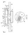
- FIG. 1is a side, cross-section view of a disc pump
- FIG. 1Ais a detail view of a section of the disc pump system of FIG. 1A taken along the line 1 A- 1 A of FIG. 1 , which shows a portion of a ring-shaped isolator having an integrated RFID tag;
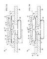
- FIG. 1Bis a detail, section view of an alternative embodiment of the disc pump wherein the isolator includes an RFID tag and a sensor;
- FIG. 1Cis a detail, section view of an alternative embodiment of the disc pump that includes an RFID tag mounted to the actuator of the disc pump and coupled to an antenna that is integral to the isolator;
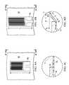
- FIG. 2Ais a cross-section view of the disc pump of FIG. 1A , showing actuator of the disc pump in a rest position;
- FIG. 2Bis a cross-section view of the disc pump of FIG. 2A , showing the actuator in a displaced position;
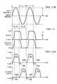
- FIG. 3Ashows a graph of the axial displacement oscillations for the fundamental bending mode of the actuator of the first disc pump of FIG. 2A ;
- FIG. 3Bshows a graph of the pressure oscillations of fluid within the cavity of the first disc pump of FIG. 2A in response to the bending mode shown in FIG. 3A ;
- FIG. 4Ais a detail view of a portion of a disc pump system that includes an actuator in a rest position
- FIG. 4Bis a detail view of a portion of a disc pump system that includes an actuator in a displaced position
- FIG. 4Cis a side, cross-section view of the portion, of the disc pump shown in FIG. 4A , whereby the actuator is in the rest position and mounted to an isolator that includes a strain gauge;
- FIG. 4Dis a side, cross-section view of the portion of the disc pump shown in FIG. 4B , whereby the actuator is in the displaced position and mounted to an isolator that includes a strain gauge;
- FIG. 5Ashows a cross-section view of the disc pump of FIG. 2A wherein the three valves are represented by a single valve illustrated in FIGS. 7A-7D ;
- FIG. 5Bshows a partial cross-section, view of a center portion of the valve of FIGS. 7A-7D ;
- FIG. 6shows a graph of pressure oscillations of fluid of within the cavities of the first disc pump of FIG. 5A as shown in FIG. 3B to illustrate the pressure differential applied across the valve of FIG. 5A as indicated by the dashed lines;
- FIG. 7Ashows a side, cross-section view of an illustrative embodiment of a valve in a closed position
- FIG. 7Bshows a cross-section view of the valve of FIG. 7A taken along line 7 B- 7 B in FIG. 7D ;
- FIG. 7Cshows a perspective view of the valve of FIG. 7B ;
- FIG. 7Dshows a top view of the valve of FIG. 7B ;
- FIG. 8Ashows a partial cross-section view of the valve in FIG. 7B in an open position when fluid flows through the valve
- FIG. 8Bshows a partial cross-section view of the valve in FIG. 7B in transition between the open and closed positions before closing;
- FIG. 8Cshows a partial cross-section view of the valve of FIG. 7B in a closed position when fluid flow is blocked by the valve;
- FIG. 9Ashows a pressure graph of an oscillating differential pressure applied across the valve of FIG. 5B according to an illustrative embodiment
- FIG. 9Bshows a fluid-flow graph of an operating cycle of the valve of FIG. 5B between an open and closed position
- FIGS. 10A and 10Bshow cross-section views of the disc pump of FIG. 3A , including a partial, detail view of the center portion of the valves and a graph of the positive and negative portion of an oscillating pressure wave, respectively, being applied within a cavity;
- FIG. 11shows the open and closed states of the valves of the fourth disc pump
- FIGS. 11A and 11Bshows the resulting flow and pressure characteristics, respectively, when the fourth disc pump is in a free-flow mode
- FIG. 12shows a graph of the maximum differential pressure provided by the fourth disc pump when the disc pump reaches the stall condition
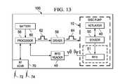
- FIG. 13is a block diagram of an illustrative circuit of a disc pump system for measuring and controlling a reduced pressure generated by the disc pump system.
- FIG. 1is a cross-section view of a disc pump system 100 coupled to a load 38 .
- the disc pump system 100includes a disc pump 10 , a substrate 28 on which the disc pump 10 is mounted, and a load 38 that is fluidly coupled to the disc pump 10 .
- the substrate 28may be a printed circuit board or any suitable rigid or semi-rigid material.
- the disc pump 10is operable to supply a positive or negative pressure to the load 38 , as described in more detail below.
- the disc pump 10includes an actuator 40 coupled to a cylindrical wall 11 of the disc pump 10 by an isolator 30 , which comprises a flexible material.
- the flexible materialis a flexible, printed circuit material.
- the flexible printed circuit materialcomprises a flexible polymer film that provides a foundation layer for the isolator 30 .
- the polymermay be a polyester (PET), polyimide (PI), polyethylene napthalate (PEN), polyetherimide (PEI), or a material with similar mechanical and electrical properties.
- the flexible circuit materialmay include one or more a laminate layers formed of a bonding adhesive.
- a metal foilsuch as a copper foil, may be used to provide one or more conductive layers to the flexible printed circuit material.
- the conductive layeris used to form circuit elements. For example, circuit paths may be etched into the conductive layer.
- the conductive layermay be applied to the foundation layer by rolling (with or without an adhesive) or by electro-deposition.
- FIG. 1Ais a partial section view taken along the line 1 A- 1 A of FIG. 1 .
- FIG. 1Ashows a top view of a portion of the disc pump system 100 that includes the actuator 40 and isolator 30 .
- the isolator 30is formed from a flexible printed circuit material that includes a Radio Frequency Identification (RFID) tag 51 .
- RFID tagis formed integrally to the isolator 30 . But in other embodiments, the RFID tag is manufactured as a separate component and installed at the surface of the isolator 30 or on the actuator 40 .
- RFIDRadio Frequency Identification
- RFIDtraditionally uses an RFID tag or label that is positioned on a target and an RFID reader that energizes and reads signals from the RFID tag.
- Most RFID tagsinclude an integrated circuit for storing and processing information, a modulator, and demodulator.
- RFID tagscan be passive tags, active RFID tags, and battery-assisted passive tags. Generally, passive tags use no battery and do not transmit information unless they are energized by an RFID reader. Active tags have an on-board power source and can transmit autonomously (i.e., without being energized by an RFID reader). Battery-assisted passive tags typically have a small battery on-board that is activated in the presence of an RFID reader.
- the RFID tag 51is formed using a silicon-on-insulator (SOI) manufacturing process and embedded within the isolator 30 as an RFID chip.
- SOIsilicon-on-insulator
- the use of such an SOI manufacturing processprovides for the ability to manufacture a very small RFID chip that is on the order of 0.15 mm ⁇ 0.15 mm in size or smaller, such as the RFID tag introduced by Hitachi (disclosed at http://www.hitachi.com/New/cnews/060206.html).
- the RFID chipmay be manufactured with an antenna, thereby slightly increasing its footprint, or by coupling the RFID chip to an external antenna.
- the external antennamay be separately manufactured and embedded in the isolator 30 with the RFID chip or formed integral to the isolator 30 and coupled to the RFID chip when the RFID chip is embedded within the isolator.
- the enhanced RFID technologyis a Wireless Identification and Sensing Platform (WISP) device.
- WISPsinvolve powering and reading a WISP device, analogous to an RFID tag (or label), with an RFID reader.
- the WISP deviceharvests the power from the RFID reader's emitted radio signals and performs sensing functions (and optionally performs computational functions).
- the WISP devicetransmits a radio signal with information to the RFID reader.
- the WISP devicereceives power from an RFID reader.
- the WISP devicehas a tag or antenna that harvests energy and a microcontroller (or processor) that can perform a variety of tasks, such as sampling sensors.
- the WISP devicereports data to the RFID reader.
- the WISP deviceincludes an integrated circuit with power harvesting circuitry, demodulator, modulator, microcontroller, sensors, and may include one or more capacitors for storing energy.
- a form of WISP technologyhas been developed by Intel Research Seattle (www.seattle.intel-research.net/wisp/).
- RFID devices as used hereinalso include WISP devices.
- the disc pump system 100includes an RFID tag 51 integrated into the isolator 30 and minimizes the addition of other circuit elements, such as sensors, within the isolator 30 .
- the RFID tag 51may be formed within the isolator 30 during the manufacturing process of the isolator 30 , e.g., as a printed circuit element or as an embedded integrated circuit, and used to store identification data. The identification data may initially only identify the isolator 30 to enable tracking of data relating to the isolator 30 .
- the isolator 30may be combined with an actuator 40 and installed into the disc pump 10 , as shown in FIG. 1 .
- the RFID datamay be monitored and associated with other components of the disc pump system 100 .
- the RFID data that initially identified the isolator 30may subsequently identify the actuator 40 , the disc pump 10 , and the disc pump system 100 .
- the RFID datamay be associated with the other components of the disc pump 10 and the disc pump system 100 in one or more external databases, so that only a low power, passive RFID tag is needed to track the isolator 30 and the other components of the disc pump system 100 .
- the RFID tag of the isolatormay be scanned using an RFID reader and associated with the disc pump 10 .
- the disc pump 10may be scanned with an RFID reader to identify and track the disc pump 10 and its components.
- the RFID tag 51is an enhanced RFID tag that includes a processor and is electrically coupled to a sensor.
- the RFID tag 51 and the sensorallow sensing and optimization of computational functions. The optimization and computational functions may be based on data collected by the sensor, as described in more detail below.
- the isolator 30includes an optional sensor, such as a strain gauge 50 that is operable to measure the deformation of the isolator 30 and in turn, the displacement ( ⁇ y) of the edge of the actuator 40 .
- the isolator 30may also include other electronic devices or circuit elements, such as a radio-frequency identification a processor or memory, as discussed in more detail below.
- FIG. 1Bshows both the RFID tag 51 and the sensor as being integral to the isolator 30
- either the RFID tag 51 or the sensormay be mounted on the actuator 40 , and electrically coupled to circuit elements on the isolator 30 for the purposes of communicating power or data from a source that is not installed on the isolator 30 or actuator 40 .
- the RFID tag 51may communicate with a very small application specific integrated circuit element that is embedded within the isolator 30 for the purpose of sensing data at the isolator 30 or within the disc pump cavity 16 and communicating the data to an external monitoring system (not shown).
- the RFID tag 51is mounted on the actuator 40 and coupled to an antenna 51 a that is integral to the isolator 30 .
- the RFID tag 51may be active or passive, and in such an application, it may be necessary to specify that the RFID tag 51 that is resistive to malfunctioning as a result of mechanical stress.
- the RFID tag 51is separately assembled and mounted to the isolator 30 .
- the RFID tag 51may be a Maxell ME-Y2000 series Coil on Chip RFID system.
- FIG. 2Ais a cross-section view of a disc pump 10 according to an illustrative embodiment.
- the disc pump 10comprises a disc pump body having a substantially elliptical shape including a cylindrical wall 11 closed at each end by end plates 12 , 13 .
- the cylindrical wall 11may be mounted to a substrate 28 , which forms the end plate 13 .
- the substrate 28may be a printed circuit board or another suitable material.
- the disc pump 10further comprises a pair of disc-shaped interior plates 14 , 15 supported within the disc pump 10 by an isolator 30 (e.g., a ring-shaped isolator) affixed to the cylindrical wall 11 of the disc pump body.
- an isolator 30e.g., a ring-shaped isolator
- the internal surfaces of the cylindrical wall 11 , the end plate 12 , the interior plate 14 , and the isolator 30form a cavity 16 within the disc pump 10 .
- the internal surfaces of the cavity 16comprise a side wall 18 which is a first portion of the inside surface of the cylindrical wall 11 that is closed at both ends by end walls 20 , 22 wherein the end wall 20 is the internal surface of the end plate 12 and the end wall 22 comprises the internal surface of the interior plate 14 and a first side of the isolator 30 .
- the end wall 22thus comprises a central portion corresponding to the inside surface of the interior plate 14 and a peripheral portion corresponding to the inside surface of the isolator 30 .
- the cylindrical wall 11 and the end plates 12 , 13may be a single component comprising the disc pump body or separate components, as shown in FIG. 2A .
- the end plate 13is formed by a separate substrate that may be a printed circuit board, an assembly board, or printed wire assembly (PWA) on which the disc pump 10 is mounted.
- PWAprinted wire assembly
- the cavity 16is substantially circular in shape, the cavity 16 may also be more generally elliptical in shape. Substantially circular may include objects that are regular circles, as well as variations on circular shapes, for example, ellipses.
- the end wall 20 defining the cavity 16is shown as being generally frusto-conical.
- the end wall 20 defining the inside surfaces of the cavity 16may include a generally planar surface that is parallel to the actuator 40 , discussed below.
- a disc pump comprising frusto-conical surfacesis described in more detail in the WO2006/111775 publication, which is incorporated by reference herein.
- the end plates 12 , 13 and cylindrical wall 11 of the disc pump bodymay be formed from any suitable rigid material including, without limitation, metal, ceramic, glass, or plastic including, without limitation, inject-molded plastic.
- the interior plates 14 , 15 of the disc pump 10together form the actuator 40 that is operatively associated with the central portion of the end wall 22 , which forms the internal surfaces of the cavity 16 .
- One of the interior plates 14 , 15must be formed of a piezoelectric material which may include any electrically active material that exhibits strain in response to an applied electrical signal, such as, for example, an electrostrictive or magnetostrictive material.
- the interior plate 15is formed of piezoelectric material that exhibits strain in response to an applied electrical signal, i.e., the active interior plate.
- the other one of the interior plates 14 , 15preferably possesses a bending stiffness similar to the active interior plate and may be formed of a piezoelectric material or an electrically inactive material, such as a metal or ceramic.
- the interior plate 14possesses a bending stiffness similar to the active interior plate 15 and is formed of an electrically inactive material, such as a metal or ceramic, i.e., the inert interior plate.
- the active interior plate 15When the active interior plate 15 is excited by an electrical current, the active interior plate 15 expands and contracts in a radial direction relative to the longitudinal axis of the cavity 16 . The expansion and contraction of the interior plate 15 causes the interior plates 14 , 15 to bend, thereby inducing an axial deflection of the end walls 22 in a direction substantially perpendicular to the end walls 22 (See FIG. 3A ).
- the isolator 30may support either one of the interior plates 14 , 15 , whether the active interior plate 15 or inert interior plate 14 , from the top or the bottom surfaces depending on the specific design and orientation of the disc pump 10 .
- the actuator 40may be replaced by a device in a force-transmitting relation with only one of the interior plates 14 , 15 such as, for example, a mechanical, magnetic or electrostatic device.
- the interior platemay be formed as an electrically inactive or passive layer of material driven into oscillation by such device (not shown) in the same manner as described above.
- the disc pump 10further comprises at least one aperture extending from the cavity 16 to the outside of the disc pump 10 , wherein the at least one aperture contains a valve to control the flow of fluid through the aperture.
- the aperturemay be located at any position in the cavity 16 where the actuator 40 generates a pressure differential as described below in more detail
- one embodiment of the disc pump 10 shown in FIGS. 2A-2Bcomprises an outlet aperture 27 , located at approximately the center of and extending through the end plate 12 .
- the aperture 27contains at least one end valve 29 .
- the aperture 27contains end valve 29 which regulates the flow of fluid in one direction as indicated by the arrows so that end valve 29 functions as an outlet valve for the disc pump 10 .
- Any reference to the aperture 27 that includes the end valve 29refers to that portion of the opening outside of the end valve 29 , i.e., outside the cavity 16 of the disc pump 10 .
- the disc pump 10further comprises at least one aperture extending through the actuator 40 , wherein the at least one aperture contains a valve to control the flow of fluid through the aperture.
- the aperturemay be located at any position on the actuator 40 where the actuator 40 generates a pressure differential.
- the illustrative embodiment of the disc pump 10 shown in FIGS. 2A-2Bcomprises an actuator aperture 31 located at approximately the center of and extending through the interior plates 14 , 15 .
- the actuator aperture 31contains an actuator valve 32 which regulates the flow of fluid in one direction into the cavity 16 , as indicated by the arrow so that the actuator valve 32 functions as an inlet valve to the cavity 16 .
- the actuator valve 32enhances the output of the disc pump 10 by augmenting the flow of fluid into the cavity 16 and supplementing the operation of the outlet valve 29 , as described in more detail below.
- the dimensions of the cavity 16 described hereinshould preferably satisfy certain inequalities with respect to the relationship between the height (h) of the cavity 16 at the side wall 18 and its radius (r) which is the distance from the longitudinal axis of the cavity 16 to the side wall 18 .
- These equationsare as follows: r/h> 1.2; and h 2 /r> 4 ⁇ 10 ⁇ 10 meters.
- the ratio of the cavity radius to the cavity heightis between about 10 and about 50 when the fluid within the cavity 16 is a gas.
- the volume of the cavity 16may be less than about 10 ml.
- the ratio of h 2 /ris preferably within a range between about 10 ⁇ 6 meters and about 10 ⁇ 7 meters, where the working fluid is a gas as opposed to a liquid.
- the cavity 16 disclosed hereinshould preferably satisfy the following inequality relating the cavity radius (r) and operating frequency (f), which is the frequency at which the actuator 40 vibrates to generate the axial displacement of the end wall 22 .
- the inequalityis as follows:
- the frequency of the oscillatory motion of the actuator 40is preferably about equal to the lowest resonant frequency of radial pressure oscillations in the cavity 16 , but may be within 20% of that value.
- the lowest resonant frequency of radial pressure oscillations in the cavity 16is preferably greater than about 500 Hz.
- the relative dimensions of the cavity 16should not be limited to cavities having the same height and radius.
- the cavity 16may have a slightly different shape requiring different radii or heights creating different frequency responses so that the cavity 16 resonates in a desired fashion to generate the optimal output from the disc pump 10 .
- the disc pump 10may function as a source of positive pressure adjacent the outlet valve 29 to pressurize a load 38 or as a source of negative or reduced pressure adjacent the actuator inlet valve 32 to depressurize a load 38 , as illustrated by the arrows.
- the loadmay be a tissue treatment system that utilizes negative pressure for treatment.
- reduced pressuregenerally refers to a pressure less than the ambient pressure where the disc pump 10 is located.
- vacuumand “negative pressure” may be used to describe the reduced pressure, the actual pressure reduction may be significantly less than the pressure reduction normally associated with a complete vacuum.
- the pressureis “negative” in the sense that it is a gauge pressure, i.e., the pressure is reduced below ambient atmospheric pressure. Unless otherwise indicated, values of pressure stated herein are gauge pressures. References to increases in reduced pressure typically refer to a decrease in absolute pressure, while decreases in reduced pressure typically refer to an increase in absolute pressure.
- the disc pump 10comprises at least one actuator valve 32 and at least one end valve 29 .
- the disc pump 10may comprise a two cavity disc pump having an end valve 29 on each side of the actuator 40 .
- FIG. 3Ashows one possible displacement profile illustrating the axial oscillation of the driven end wall 22 of the cavity 16 .
- the solid curved line and arrowsrepresent the displacement of the driven end wall 22 at one point in time, and the dashed curved line represents the displacement of the driven end wall 22 one half-cycle later.
- the displacement as shown in this figure and the other figuresis exaggerated.
- the actuator 40is not rigidly mounted at its perimeter, and is instead suspended by the isolator 30 , the actuator 40 is free to oscillate about its center of mass in its fundamental mode. In this fundamental mode, the amplitude of the displacement oscillations of the actuator 40 is substantially zero at an annular displacement node 42 located between the center of the driven end wall 22 and the side wall 18 .
- a central displacement anti-node 43exists near the center of the actuator 40 and a peripheral displacement anti-node 43 ′ exists near the perimeter of the actuator 40 .
- the central displacement anti-node 43is represented by the dashed curve after one half-cycle.
- FIG. 3Bshows one possible pressure oscillation profile illustrating the pressure oscillation within the cavity 16 resulting from the axial displacement oscillations shown in FIG. 3A .
- the solid curved line and arrowsrepresent the pressure at one point in time.
- the amplitude of the pressure oscillationshas a peripheral pressure anti-node 45 ′ near the side wall 18 of the cavity 16 .
- the amplitude of the pressure oscillationsis substantially zero at the annular pressure node 44 between the central pressure anti-node 45 and the peripheral pressure anti-node 45 ′.
- the amplitude of the pressure oscillationsas represented by the dashed line that has a negative central pressure anti-node 47 near the center of the cavity 16 with a peripheral pressure anti-node 47 ′ and the same annular pressure node 44 .
- the radial dependence of the amplitude of the pressure oscillations in the cavity 16may be approximated by a Bessel function of the first kind.
- the pressure oscillations described aboveresult from the radial movement of the fluid in the cavity 16 and so will be referred to as the “radial pressure oscillations” of the fluid within the cavity 16 as distinguished from the axial displacement oscillations of the actuator 40 .
- the radial dependence of the amplitude of the axial displacement oscillations of the actuator 40should approximate a Bessel function of the first kind so as to match more closely the radial dependence of the amplitude of the desired pressure oscillations in the cavity 16 (the “mode-shape” of the pressure oscillation).
- the mode-shape of the displacement oscillationssubstantially matches the mode-shape of the pressure oscillations in the cavity 16 thus achieving mode-shape matching or, more simply, mode-matching.
- the axial displacement oscillations of the actuator 40 and the corresponding pressure oscillations in the cavity 16have substantially the same relative phase across the full surface of the actuator 40 , wherein the radial position of the annular pressure node 44 of the pressure oscillations in the cavity 16 and the radial position of the annular displacement node 42 of the axial displacement oscillations of actuator 40 are substantially coincident.
- the radial position of the annular displacement node 42will necessarily lie inside the radius of the actuator 40 when the actuator 40 vibrates in its fundamental bending mode as illustrated in FIG. 3A .
- the radius of the actuatorshould preferably be greater than the radius of the annular pressure node 44 to optimize mode-matching.
- the radius of the annular pressure node 44would be approximately 0.63 of the radius from the center of the end wall 22 to the side wall 18 , i.e., the radius of the cavity 16 (“r”), as shown in FIG. 2A . Therefore, the radius of the actuator 40 (r act ) should preferably satisfy the following inequality: r act ⁇ 0.63 r.
- the isolator 30may be a flexible membrane that enables the edge of the actuator 40 to move more freely as described above by bending and stretching in response to the vibration of the actuator 40 as shown by the displacement at the peripheral displacement anti-node 43 ′ in FIG. 3A .
- the isolator 30overcomes the potential damping effects of the side wall 18 on the actuator 40 by providing a low mechanical impedance support between the actuator 40 and the cylindrical wall 11 of the disc pump 10 , thereby reducing the damping of the axial oscillations at the peripheral displacement anti-node 43 ′ of the actuator 40 .
- the isolator 30minimizes the energy being transferred from the actuator 40 to the side wall 18 with the outer peripheral edge of the isolator 30 remaining substantially stationary.
- the annular displacement node 42will remain substantially aligned with the annular pressure node 44 to maintain the mode-matching condition of the disc pump 10 .
- the axial displacement oscillations of the driven end wall 22continue to efficiently generate oscillations of the pressure within the cavity 16 from the central pressure anti-nodes 45 , 47 to the peripheral pressure anti-nodes 45 ′, 47 ′ at the side wall 18 as shown in FIG. 3B .
- FIG. 4Ais a detail view of a portion of the disc pump 10 that includes a strain gauge 50 mounted on the isolator 30 of the disc pump 10 .
- the isolator 30comprises a flexible printed circuit material.
- the strain gauge 50is attached to the isolator 30 and may be used to compute the displacement of the edge of the actuator 40 .
- the strain gauge 50indirectly measures the displacement of the edge of the actuator 40 , thereby alleviating the need to include a sensor on the substrate 28 .
- the strain gauge 50measures the strain, i.e., deformation, of the isolator 30 and the measured deformation of the isolator 30 is used to derive the displacement of the edge of the actuator 40 .
- the strain gauge 50may comprise a metallic pattern that is integrated into the flexible printed circuit material that forms the isolator 30 .
- the strain gauge 50is integral to the isolator 30 so that the strain gauge 50 deforms as the isolator 30 deforms.
- the strain gauge 50is affixed to the surface of the isolator 30 .
- the deformation of the strain gauge 50results in a change in the electrical resistance of the strain gauge 50 , which can be measured using, for example, a Wheatstone bridge.
- the change in electrical resistanceis related to the deformation of the isolator 30 and, therefore, the displacement of the actuator 40 , by a gauge factor.
- the displacement of the edge of the actuator 40 and the associated pressure differential across the disc pump 10can be determined by analyzing the changes in the electrical resistance of the strain gauge 50 .
- the strain gauge 50is integral to the isolator 30 and formed within the isolator 30 during the manufacturing process.
- the strain gauge 50may be formed by circuit elements included in an etched copper layer of a flexible printed circuit board material.
- the strain gauge 50may be manufactured separately and attached to the isolator 30 during the assembly of the disc pump 10 .
- FIG. 4Bis a detail view of a section of a disc pump 10 that shows the strain gauge 50 in a deformed state.
- the strain gauge 50 of FIG. 4Bhas a length (l 2 ) that is longer than the initial length (l 1 ) of the strain gauge 50 in its non-deformed state.
- FIG. 4Cis a side, detail view of a cross section of the portion of the disc pump 10 shown in FIG. 4A
- FIG. 4Dis a side, detail view of a cross section of the portion of the disc pump 10 shown in FIG. 4B .
- the deformed length (l 2 ) of the portion of the isolatorcan be computed by analyzing the change in the electrical resistance of the strain gauge 50 .
- the displacement ( ⁇ y) of the edge of the actuator 40may be computed by considering the three dimensions (l 1 , l 2 and ⁇ y) as the three sides of a right triangle.
- the displacement ( ⁇ y) of the edge of the actuator 40is a function of both the bending of the actuator 40 in response to a piezoelectric drive signal and the bulk displacement of the actuator 40 resulting from the difference in pressure on either side of the actuator 40 .
- the displacement of the edge of the actuator 40 that results from the bending of the actuator 40changes at a high frequency that corresponds to the resonant frequency of the disc pump 10 .
- the displacement of the edge of actuator 40 that results from a difference in pressure on opposing sides of the actuator 40the pressure-related displacement of the actuator 40
- the pressure-related displacement ( ⁇ y) of the edge of the actuator 40bears a direct correlation to the pressure differential across the actuator 40 and the corresponding pressure differential across the disc pump 10 .
- the net forceis a result of the pressure being higher on one side of the actuator 40 than the other. Since the actuator 40 is mounted to the isolator 30 , which is made from a resilient material that has a spring constant (k), the actuator 40 moves in response to the pressure-related force.
- non-linear spring characteristics of an isolatormay also be determined in order to equate the pressure-related displacement of the edge of the actuator 40 to the pressure differential across the disc pump system 100 .
- the displacement ( ⁇ y)may be measured or calculated in real-time or utilizing a specified sampling frequency of strain gauge data to determine the position of the edge of actuator 40 relative to the substrate 28 .
- the position of the edge of the actuator 40is computed as an average or mean position over a given time period to indicate the displacement ( ⁇ y) resulting from the bending of the actuator 40 .
- the reduced pressure within the cavity 16 of the disc pump 10may be determined by sensing the displacement ( ⁇ y) of the edge of the actuator 40 without the need for pressure sensors that directly measure the pressure provided to a load. This may be desirable because pressure sensors that directly measure pressure may be too bulky or too expensive for application in measuring the pressure provided by the disc pump 10 within a reduced pressure system, for example.
- FIG. 5Athe disc pump 10 of FIG. 1A is shown with the valves 29 , 32 , both of which are substantially similar in structure as represented, for example, by a valve 110 shown in FIGS. 7A-7D and having a center portion 111 shown in FIG. 5B .
- the following description associated with FIGS. 5-9are all based on the function of a single valve 110 that may be positioned in any one of the apertures 27 , 31 of the disc pump 10 .
- FIG. 6shows a graph of the pressure oscillations of fluid within the disc pump 10 as shown in FIG. 3B .
- the valve 110allows fluid to flow in only one direction as described above.
- the valve 110may be a check valve or any other valve that allows fluid to flow in only one direction.
- Some valve typesmay regulate fluid flow by switching between an open and closed position.
- the valves 29 , 32must have an extremely fast response time such that they are able to open and close on a timescale significantly shorter than the timescale of the pressure variation.
- One embodiment of the valves 29 , 32achieves this by employing an extremely light flap valve which has low inertia and consequently is able to move rapidly in response to changes in relative pressure across the valve structure.
- valve 110is such a flap valve for the disc pump 10 according to an illustrative embodiment.
- the valve 110comprises a substantially cylindrical wall 112 that is ring-shaped and closed at one end by a retention plate 114 and at the other end by a sealing plate 116 .
- the inside surface of the wall 112 , the retention plate 114 , and the sealing plate 116form a cavity 115 within the valve 110 .
- the valve 110further comprises a substantially circular flap 117 disposed between the retention plate 114 and the sealing plate 116 , but adjacent the sealing plate 116 .
- the circular flap 117may be disposed adjacent the retention plate 114 in an alternative embodiment as will be described in more detail below, and in this sense the flap 117 is considered to be “biased” against either one of the sealing plate 116 or the retention plate 114 .
- the peripheral portion of the flap 117is sandwiched between the sealing plate 116 and the ring-shaped wall 112 so that the motion of the flap 117 is restrained in the plane substantially perpendicular the surface of the flap 117 .
- the motion of the flap 117 in such planemay also be restrained by the peripheral portion of the flap 117 being attached directly to either the sealing plate 116 or the wall 112 , or by the flap 117 being a close fit within the ring-shaped wall 112 , in an alternative embodiment.
- the remainder of the flap 117is sufficiently flexible and movable in a direction substantially perpendicular to the surface of the flap 117 , so that a force applied to either surface of the flap 117 will motivate the flap 117 between the sealing plate 116 and the retention plate 114 .
- the retention plate 114 and the sealing plate 116both have holes 118 and 120 , respectively, which extend through each plate.
- the flap 117also has holes 122 that are generally aligned with the holes 118 of the retention plate 114 to provide a passage through which fluid may flow as indicated by the dashed arrows 124 in FIGS. 5B and 8A .
- the holes 122 in the flap 117may also be partially aligned, i.e., having only a partial overlap, with the holes 118 in the retention plate 114 .
- the holes 118 , 120 , 122are shown to be of substantially uniform size and shape, they may be of different diameters or even different shapes without limiting the scope of the invention.
- the holes 118 and 120form an alternating pattern across the surface of the plates as shown by the solid and dashed circles, respectively, in FIG. 7D .
- the holes 118 , 120 , 122may be arranged in different patterns without affecting the operation of the valve 110 with respect to the functioning of the individual pairings of holes 118 , 120 , 122 as illustrated by individual sets of the dashed arrows 124 .
- the pattern of holes 118 , 120 , 122may be designed to increase or decrease the number of holes to control the total flow of fluid through the valve 110 as required. For example, the number of holes 118 , 120 , 122 may be increased to reduce the flow resistance of the valve 110 to increase the total flow rate of the valve 110 .
- the center portion 111 of the valve 110illustrates how the flap 117 is motivated between the sealing plate 116 and the retention plate 114 when a force is applied to either surface of the flap 117 .
- the valve 110is in a “normally closed” position because the flap 117 is disposed adjacent the sealing plate 116 where the holes 122 of the flap are offset or not aligned with the holes 118 of the sealing plate 116 .
- this “normally closed” positionthe flow of fluid through the sealing plate 116 is substantially blocked or covered by the non-perforated portions of the flap 117 as shown in FIGS. 7A and 7B .
- valve 110moves from the normally closed position to an “open” position over a time period, i.e., an opening time delay (T o ), allowing fluid to flow in the direction indicated by the dashed arrows 124 .
- T oopening time delay
- a closing time delayT c
- the flap 117may be biased against the retention plate 114 with the holes 118 , 122 aligned in a “normally open” position. In this embodiment, applying positive pressure against the flap 117 will be necessary to motivate the flap 117 into a “closed” position.
- valve operationin relation to valve operation are intended to include cases in which substantial (but incomplete) sealing or blockage occurs, such that the flow resistance of the valve is greater in the “closed” position than in the “open” position.
- the operation of the valve 110is a function of the change in direction of the differential pressure ( ⁇ P) of the fluid across the valve 110 .
- the differential pressurehas been assigned a negative value ( ⁇ P) as indicated by the downward pointing arrow.
- ⁇ Pnegative value
- the fluid pressure at the outside surface of the retention plate 114is greater than the fluid pressure at the outside surface of the sealing plate 116 .
- This negative differential pressure ( ⁇ P)drives the flap 117 into the fully closed position as described above wherein the flap 117 is pressed against the sealing plate 116 to block the holes 120 in the sealing plate 116 , thereby substantially preventing the flow of fluid through the valve 110 .
- the changing differential pressurecycles the valve 110 between closed and open positions based on the direction (i.e., positive or negative) of the differential pressure across the valve 110 .
- the flap 117could be biased against the retention plate 114 in an open position when no differential pressure is applied across the valve 110 , i.e., the valve 110 would then be in a “normally open” position.
- the operation of the valve 110is a function of the change in direction of the differential pressure ( ⁇ P) of the fluid across the valve 110 .
- the differential pressure ( ⁇ P)is assumed to be substantially uniform across the entire surface of the retention plate 114 because (1) the diameter of the retention plate 114 is small relative to the wavelength of the pressure oscillations in the cavity 115 , and (2) the valve 110 is located near the center of the cavity 16 where the amplitude of the positive central pressure anti-node 45 is relatively constant as indicated by the positive square-shaped portion 55 of the positive central pressure anti-node 45 and the negative square-shaped portion 65 of the negative central pressure anti-node 47 shown in FIG. 6 . Therefore, there is virtually no spatial variation in the pressure across the center portion 111 of the valve 110 .
- FIG. 9further illustrates the dynamic operation of the valve 110 when it is subject to a differential pressure, which varies in time between a positive value (+ ⁇ P) and a negative value ( ⁇ P). While in practice the time-dependence of the differential pressure across the valve 110 may be approximately sinusoidal, the time-dependence of the differential pressure across the valve 110 is approximated as varying in the square-wave form shown in FIG. 9A to facilitate explanation of the operation of the valve.
- the positive differential pressure 55is applied across the valve 110 over the positive pressure time period (t p +) and the negative differential pressure 65 is applied across the valve 110 over the negative pressure time period (t p ⁇ ) of the square wave.
- FIG. 9Billustrates the motion of the flap 117 in response to this time-varying pressure.
- the retention plate 114 and the sealing plate 116should be strong enough to withstand the fluid pressure oscillations to which they are subjected without significant mechanical deformation.
- the retention plate 114 and the sealing plate 116may be formed from any suitable rigid material, such as glass, silicon, ceramic, or metal.
- the holes 118 , 120 in the retention plate 114 and the sealing plate 116may be formed by any suitable process including chemical etching, laser machining, mechanical drilling, powder blasting, and stamping.
- the retention plate 114 and the sealing plate 116are formed from sheet steel between 100 and 200 microns thick, and the holes 118 , 120 therein are formed by chemical etching.
- the flap 117may be formed from any lightweight material, such as a metal or polymer film.
- the flap 117may be formed from a thin polymer sheet between 1 micron and 20 microns in thickness.
- the flap 117may be formed from polyethylene terephthalate (PET) or a liquid crystal polymer film approximately 3 microns in thickness.
- FIGS. 10A and 10Ban exploded view of the two-valve disc pump 10 is shown that utilizes valve 110 as valves 29 and 32 .
- the actuator valve 32gates airflow 232 between the actuator aperture 31 and cavity 16 of the disc pump 10 ( FIG. 10A ), while end valve 29 gates airflow between the cavity 16 and the outlet aperture 27 of the disc pump 10 ( FIG. 10B ).
- Each of the figuresalso shows the pressure generated in the cavity 16 as the actuator 40 oscillates.
- Both of the valves 29 and 32are located near the center of the cavity 16 where the amplitudes of the positive and negative central pressure anti-nodes 45 and 47 , respectively, are relatively constant as indicated by the positive and negative square-shaped portions 55 and 65 , respectively.
- valves 29 and 32are both biased in the closed position as shown by the flap 117 and operate as described above when the flap 117 is motivated to the open position as indicated by flap 117 ′.
- the figuresalso show an exploded view of the positive and negative square-shaped portions 55 , 65 of the central pressure anti-nodes 45 , 47 and their simultaneous impact on the operation of both valves 29 , 32 and the corresponding airflow 229 and 232 , respectively, generated through each one.
- FIGS. 11, 11A and 11Bthe open and closed states of the valves 29 and 32 ( FIG. 11 ) and the resulting flow characteristics of each one ( FIG. 11A ) are shown as related to the pressure in the cavity 16 ( FIG. 11B ).
- the actuator aperture 31 and the outlet aperture 27 of the disc pump 10are both at ambient pressure and the actuator 40 begins vibrating to generate pressure oscillations within the cavity 16 as described above, air begins flowing alternately through the valves 29 , 32 .
- air flows from the actuator aperture 31 to the outlet aperture 27 of the disc pump 10i.e., the disc pump 10 begins operating in a “free-flow” mode.
- the actuator aperture 31 of the disc pump 10may be supplied with air at ambient pressure while the outlet aperture 27 of the disc pump 10 is pneumatically coupled to a load (not shown) that becomes pressurized through the action of the disc pump 10 .
- the actuator aperture 31 of the disc pump 10may be pneumatically coupled to a load (not shown) that becomes depressurized to generate a negative pressure in the load, such as a wound dressing, through the action of the disc pump 10 .
- the square-shaped portion 55 of the positive central pressure anti-node 45is generated within the cavity 16 by the vibration of the actuator 40 during one half of the disc pump cycle as described above.
- the square-shaped portion 55 of the positive central anti node 45creates a positive differential pressure across the end valve 29 and a negative differential pressure across the actuator valve 32 .
- the actuator valve 32begins closing and the end valve 29 begins opening so that the actuator valve 32 blocks the airflow 232 x through the actuator aperture 31 , while the end valve 29 opens to release air from within the cavity 16 allowing the airflow 229 to exit the cavity 16 through the outlet aperture 27 .
- the actuator valve 32 closes and the end valve 29 opensFIG. 11
- the airflow 229 at the outlet aperture 27 of the disc pump 10increases to a maximum value dependent on the design characteristics of the end valve 29 ( FIG. 11A ).
- the opened end valve 29allows airflow 229 to exit the disc pump cavity 16 ( FIG. 11B ) while the actuator valve 32 is closed.
- the square-shaped portion 65 of the negative central anti-node 47is generated within the cavity 16 by the vibration of the actuator 40 during the second half of the disc pump cycle as described above.
- the square-shaped portion 65 of the negative central anti-node 47creates a negative differential pressure across the end valve 29 and a positive differential pressure across the actuator valve 32 .
- the actuator valve 32begins opening and the end valve 29 begins closing so that the end valve 29 blocks the airflow 229 x through the outlet aperture 27 , while the actuator valve 32 opens allowing air to flow into the cavity 16 as shown by the airflow 232 through the actuator aperture 31 .
- the actuator valve 32opens and the end valve 29 closes ( FIG. 11 )
- the airflow at the outlet aperture 27 of the disc pump 10is substantially zero except for the small amount of backflow 329 as described above ( FIG. 11A ).
- the opened actuator valve 32allows airflow 232 into the disc pump cavity 16 ( FIG. 11B ) while the end valve 29 is closed.
- the airflow 232begins to drop until the differential pressure across the actuator valve 32 reaches zero.
- the actuator aperture 31 of the disc pump 10is held at ambient pressure and the outlet aperture 27 of the disc pump 10 is pneumatically coupled to a load that becomes pressurized through the action of the disc pump 10 , the pressure at the outlet aperture 27 of the disc pump 10 begins to increase until the outlet aperture 27 of the disc pump 10 reaches a maximum pressure at which time the airflow from the actuator aperture 31 to the outlet aperture 27 is negligible, i.e., the “stall” condition.
- FIG. 12illustrates the pressures within the cavity 16 and outside the cavity 16 at the actuator aperture 31 and the outlet aperture 27 when the disc pump 10 is in the stall condition. More specifically, the mean pressure in the cavity 16 is approximately 1P above the inlet pressure (i.e.
- the pressure at the center of the cavity 16varies between approximately ambient pressure and approximately ambient pressure plus 2P.
- the pressure oscillation in the cavity 16results in a sufficient positive differential pressure across either inlet valve 32 or outlet valve 29 to significantly open either valve to allow any airflow through the disc pump 10 .
- the synergistic action of the two valves 29 , 32 described aboveis capable of increasing the differential pressure between the outlet aperture 27 and the actuator aperture 31 to a maximum differential pressure of 2P, double that of a single valve disc pump.
- the outlet pressure of the two-valve disc pump 10increases from ambient in the free-flow mode to a pressure of approximately ambient plus 2P when the disc pump 10 reaches the stall condition.
- the isolator 30is formed from a flexible printed circuit material
- electronic elementsmay be incorporated into the structure of the isolator 30 .
- the isolatorincludes a sensor, such as a strain gauge 50 , to gather data related to the performance of the isolator 30 and movement of the actuator 40 .
- the sensoris coupled to the RFID tag 51 .
- the RFID tag 51is a WISP device that includes a processor.
- the WISP devicemay also include a memory and power source that are also formed integrally with, or embedded within, the isolator 30 .
- the isolator 30may include an electrical coupling from the sensor to a remote bus and other electronic devices not formed integrally to or affixed to the isolator 30 .
- the other electronic devicesmay include a remote RFID tag, a remote processor, a remote memory, and a remote power source.
- the remote componentsmay be located adjacent the isolator 30 or at a distance away from the isolator 30 .
- the senormeasures performance parameters of the disc pump 10 , which may include the maximum and average displacements of the actuator 40 and deformation experienced by the isolator 30 over time, or other parameters.
- the measured performance parametersare transmitted to the RFID tag 51 in real time, and in turn transmitted to a remote computing unit.
- the senormeasures and communicates performance parameters to the WISP RFID tag 51 that is integral to the isolator 30 .
- the performance parametersare stored in a memory that is located on the isolator 30 , and periodically transmitted to a remote computing unit via the RFID tag 51 .
- the remote computing unitmay be the computing unit that includes the processor 56 , discussed with regard to FIG. 13 , to facilitate the control and operation of the disc pump system 100 , including the disc pump 10 .
- the sensormay be the strain gauge 50 that measures displacement of the edge of the actuator 40 , thereby alleviating the need to include a sensor on the substrate 28 .
- the strain gauge 50is a device used to measure the strain of the isolator 30 , and may comprise a metallic coil pattern that is integrated into the flexible printed circuit material.
- the strain gauge 50is integral to the isolator 30 , so that the strain gauge 50 deforms as the isolator 30 deforms.
- the deformation of the strain gauge 50results in a change in the electrical resistance of the strain gauge 50 .
- the change in electrical resistanceis related to the pressure-related deformation of the isolator 30 , and therefore the displacement of the actuator 40 , by a gauge factor. Accordingly, the displacement of the actuator 40 and the associated pressure differential across the disc pump 10 can be determined using the stain gauge 50 .
- the RFID tag 51may be located on the actuator 40 at a displacement node (described above).
- the strength of the signal from the RFID tag 51may be measured by a remote sensor placed at a static location for the purposes of determining the displacement of the actuator 40 . Using the signal strength as a measure of the displacement of the actuator 40 , allows the RFID tag 51 to determine the associated pressure differential across the disc pump 10 .
- FIG. 13is a block diagram that illustrates the functionality of the disc pump system 100 that includes a sensor and the RFID tag 51 .
- the sensormay be, for example, the strain gauge 50 , that is operable to measure the displacement of an actuator 40 , as described above. Other sensors may also be utilized as part of the disc pump system 100 .
- the disc pump system 100comprises a battery 60 to power the disc pump system 100 .
- the elements of the disc pump system 100are interconnected and communicate through wires, paths, traces, leads, and other conductive elements.
- the disc pump system 100also includes a controller or processor 56 and a driver 58 .
- the processor 56is adapted to communicate with the driver 58 .
- the driver 58is functional to receive a control signal 62 from the processor 56 .
- the driver 58generates a drive signal 64 that energizes the actuator 40 in the first disc pump 10 .
- the actuator 40may include a piezoelectric component that generates the radial pressure oscillations of the fluid within the cavities of the disc pump 10 when energized causing fluid flow through the cavity to pressurize or depressurize the load as described above.
- the actuator 40may be driven by an electrostatic or electromagnetic drive mechanism.
- the isolator 30 of the disc pump 10is formed from a flexible, printed circuit material and may include the integrated sensor.
- the optional sensormay be coupled to the RFID tag 51 via a processor or a bus.
- the RFID tag 51 and the processorare in turn coupled to a power supply.
- the senormay be used to measure performance data related to the operation of the disc pump 10 , including data related to the displacement of the actuator 40 and the deformation of the isolator 30 .
- the measured datamay have a dynamic value or a static value, depending on whether the pump is operational, in a free flow state, or in a stall state.
- the sensormay return dynamic performance data that can be used to determine the pressure differential created by the pump or the condition of the isolator 30 .
- the performance datamay be used to determine the maximum pressure differentials generated by the disc pump 10 over time, as well as the average pressure differential over time as the disc pump 10 transitions from the free-flow condition to the stall condition.
- the sensormay be used to determine the pressure differential across the disc pump 10 in a static condition, i.e., when the disc pump 10 is stopped or when the pump has reached the stall condition.
- the performance data measured by the sensormay be transferred to a remote computing unit via the RFID tag 51 .
- the disc pump system 100includes an RFID reader 49 , which is a receiver or transceiver that receives RFID communications from the RFID tag. 51 .
- the RFID reader 49may also wirelessly supply power to the RFID tag 51 .
- the transmitted poweris stored by the power supply, and used to power the devices located on the isolator 30 , including the RFID tag 51 , the processor, the memory, and the sensor.
- Data transmitted from the RFID tag 51 to the RFID reader 49is transmitted to the processor 56 of the disc pump 10 .
- the processor 56may utilize the data as feedback to adjust the control signal 62 and corresponding drive signals 64 for regulating the pressure at the load 38 .
- the processor 56calculates the flow rate provided by the disc pump system 100 as a function of the received data that indicates, for example, the pressures generated at the disc pump 10 , as described above.
- the processor 56 , driver 58 , and other control circuitry of the disc pump system 100may be referred to as an electronic circuit.
- the processor 56may be circuitry or logic enabled to control functionality of the disc pump 10 .
- the processor 56may function as or comprise microprocessors, digital signal processors, application-specific integrated circuits (ASIC), central processing units, digital logic or other devices suitable for controlling an electronic device including one or more hardware and software elements, executing software, instructions, programs, and applications, converting and processing signals and information, and performing other related tasks.
- the processor 56may be a single chip or integrated with other computing or communications elements.
- the processor 56may include or communicate with a memory.
- the memorymay be a hardware element, device, or recording media configured to store data for subsequent retrieval or access at a later time
- the memorymay be static or dynamic memory in the form of random access memory, cache, or other miniaturized storage medium suitable for storage of data, instructions, and information.
- the electronic circuitmay be analog circuitry that is configured to perform the same or analogous functionality for measuring the pressure and controlling the displacement of the actuator 40 in the cavities of the disc pump 10 , as described above.
- the disc pump system 100may also include an RF transceiver 70 for communicating information and data relating to the performance of the disc pump system 100 including, for example, the flow rate, the current pressure measurements, the actual displacement ( ⁇ y) of the actuator 40 , and the current life of the battery 60 via wireless signals 72 and 74 transmitted from and received by the RF transceiver 70 .
- the disc pump system 100may utilize a communications interface that comprises RF transceiver 70 , infrared, or other wired or wireless signals to communicate with one or more external devices.
- the RF transceiver 70may utilize Bluetooth, WiFi, WiMAX, or other communications standards or proprietary communications systems.
- the RF transceiver 70may send the signals 72 to a computing device that stores a database of pressure readings for reference by a medical professional.
- the computing devicemay be a computer, mobile device, or medical equipment device that may perform processing locally or further communicate the information to a central or remote computer for processing of the information and data.
- the RF transceiver 70may receive the signals 72 for externally regulating the pressure generated by the disc pump system 100 at the load 38 based on the motion of the actuator 40 .
- the driver 58is an electrical circuit that energizes and controls the actuator 40 .
- the driver 58may be a high-power transistor, amplifier, bridge, and/or filters for generating a specific waveform as part of the drive signal 64 .
- Such a waveformmay be configured by the processor 56 and the driver 58 to provide drive signal 64 that causes the actuator 40 to vibrate in an oscillatory motion at the frequency (f), as described in more detail above.
- the oscillatory displacement motion of the actuator 40generates the radial pressure oscillations of the fluid within the cavities of the disc pump 10 in response to the drive signal 64 to generate pressure at the load 38 .
- the disc pump system 100may include a user interface for displaying information to a user.
- the user interfacemay include a display, audio interface, or tactile interface for providing information, data, or signals to a user.
- a miniature LED screenmay display the pressure being applied by the disc pump system 100 .
- the user interfacemay also include buttons, dials, knobs, or other electrical or mechanical interfaces for adjusting the performance of the disc pump, and particularly, the reduced pressure generated. For example, the pressure may be increased or decreased by adjusting a knob or other control element that is part of the user interface.
- the implementation of a sensor on the isolator 30can negate the need for a remote pressure sensor to measure the displacement of an actuator 40 in a disc pump 10 .
- the measured displacement or other datacan be used to determine the pressure differential generated by the disc pump 10 .
- a sensor and wireless transmission systemcan be manufactured directly onto the isolator 30 and used to directly measure, for example, the strain on the isolator 30 .
- the measured strain on the isolator 30may be used to determine the corresponding displacement of the edge of the actuator 40 , which enables the computation of the differential pressure generated by the disc pump 10 .
- the null electrical resistance of the strain gauge 50may be measured before the disc pump 10 is coupled to the load 38 to ensure that there is not an externally generated, or pre-existing pressure differential across the actuator 40 .
- the null resistancemay then be compared to the electrical resistance of the strain gauge 50 over time to detect changes in isolator 30 .
- this strain gauge datamay be gathered to indicate the condition of the isolator 30 . For example, strain gauge data that indicates that the resiliency of the isolator 30 is diminishing may indicate a worn or damaged isolator 30 .
- strain gauge data indicating that there is less strain, or less deformation of the isolator 30 despite the application of a drive signal to the actuator 40may indicate a pump defect, such as delamination of the isolator 30 .
- the rate of change of pressurewhich can be measured using data gathered by the strain gauge, may be used to indicate a flow rate of the disc pump.
Landscapes
- Engineering & Computer Science (AREA)
- Mechanical Engineering (AREA)
- General Engineering & Computer Science (AREA)
- Reciprocating Pumps (AREA)
- Measuring Fluid Pressure (AREA)
Abstract
Description
r/h>1.2; and
h2/r>4×10−10meters.
Claims (17)
Priority Applications (1)
| Application Number | Priority Date | Filing Date | Title |
|---|---|---|---|
| US13/762,076US9422934B2 (en) | 2012-02-10 | 2013-02-07 | Systems and methods for monitoring a disc pump system using RFID |
Applications Claiming Priority (2)
| Application Number | Priority Date | Filing Date | Title |
|---|---|---|---|
| US201261597493P | 2012-02-10 | 2012-02-10 | |
| US13/762,076US9422934B2 (en) | 2012-02-10 | 2013-02-07 | Systems and methods for monitoring a disc pump system using RFID |
Publications (2)
| Publication Number | Publication Date |
|---|---|
| US20130209277A1 US20130209277A1 (en) | 2013-08-15 |
| US9422934B2true US9422934B2 (en) | 2016-08-23 |
Family
ID=47827422
Family Applications (1)
| Application Number | Title | Priority Date | Filing Date |
|---|---|---|---|
| US13/762,076Active2034-12-03US9422934B2 (en) | 2012-02-10 | 2013-02-07 | Systems and methods for monitoring a disc pump system using RFID |
Country Status (7)
| Country | Link |
|---|---|
| US (1) | US9422934B2 (en) |
| EP (1) | EP2812577B1 (en) |
| JP (1) | JP2015513027A (en) |
| CN (1) | CN104081052A (en) |
| AU (1) | AU2013216970A1 (en) |
| CA (1) | CA2858112A1 (en) |
| WO (1) | WO2013119840A1 (en) |
Cited By (4)
| Publication number | Priority date | Publication date | Assignee | Title |
|---|---|---|---|---|
| US20130274629A1 (en)* | 2012-04-12 | 2013-10-17 | Elwha LLC a limited liability company of the State of Delaware | Appurtenances for reporting information regarding wound dressings |
| US20140298927A1 (en)* | 2012-04-12 | 2014-10-09 | Elwha LLC, a limited liability company of the State of Delaware | Appurtenances including sensors for reporting information regarding wound dressings |
| US20140298928A1 (en)* | 2012-04-12 | 2014-10-09 | Elwha Llc | Wound dressing monitoring systems including appurtenances for wound dressings |
| US10226212B2 (en) | 2012-04-12 | 2019-03-12 | Elwha Llc | Appurtenances to cavity wound dressings |
Families Citing this family (17)
| Publication number | Priority date | Publication date | Assignee | Title |
|---|---|---|---|---|
| US7753894B2 (en) | 2004-04-27 | 2010-07-13 | Smith & Nephew Plc | Wound cleansing apparatus with stress |
| ES2715605T3 (en) | 2007-11-21 | 2019-06-05 | Smith & Nephew | Wound dressing |
| US9084845B2 (en) | 2011-11-02 | 2015-07-21 | Smith & Nephew Plc | Reduced pressure therapy apparatuses and methods of using same |
| TW201326773A (en)* | 2011-12-30 | 2013-07-01 | Ind Tech Res Inst | Adjustment apparatus for pressure sensor and adjustment method thereof |
| AU2013237095B2 (en) | 2012-03-20 | 2017-10-05 | Smith & Nephew Plc | Controlling operation of a reduced pressure therapy system based on dynamic duty cycle threshold determination |
| US9427505B2 (en) | 2012-05-15 | 2016-08-30 | Smith & Nephew Plc | Negative pressure wound therapy apparatus |
| WO2016019039A1 (en) | 2014-07-30 | 2016-02-04 | S.P.M. Flow Control, Inc. | Band with rfid chip holder and identifying component |
| EP3237032B1 (en) | 2014-12-22 | 2024-08-07 | Smith & Nephew plc | Negative pressure wound therapy apparatus |
| TWI568933B (en)* | 2015-03-06 | 2017-02-01 | 科際精密股份有限公司 | Piezoelectric pump and piezoelectric pump assembly |
| US11037039B2 (en) | 2015-05-21 | 2021-06-15 | S.P.M. Flow Control, Inc. | Method and system for securing a tracking device to a component |
| CA3013437C (en)* | 2015-08-14 | 2024-03-05 | S.P.M. Flow Control, Inc. | Carrier and band assembly for identifying and managing a component of a system associated with a wellhead |
| US10602284B2 (en)* | 2016-07-18 | 2020-03-24 | Cochlear Limited | Transducer management |
| TWI602995B (en)* | 2016-09-05 | 2017-10-21 | 研能科技股份有限公司 | Fluid control device |
| TWI625468B (en) | 2016-09-05 | 2018-06-01 | 研能科技股份有限公司 | Fluid control device |
| TWI613367B (en) | 2016-09-05 | 2018-02-01 | 研能科技股份有限公司 | Fluid control device |
| EP3604876B2 (en) | 2018-08-03 | 2024-04-03 | SISTO Armaturen S.A. | Membrane diagnosis via air interface |
| DE112020007326A5 (en)* | 2020-06-17 | 2023-04-06 | Fraunhofer-Gesellschaft zur Förderung der angewandten Forschung eingetragener Verein | Micro diaphragm pump device |
Citations (129)
| Publication number | Priority date | Publication date | Assignee | Title |
|---|---|---|---|---|
| US1355846A (en) | 1920-02-06 | 1920-10-19 | David A Rannells | Medical appliance |
| US2547758A (en) | 1949-01-05 | 1951-04-03 | Wilmer B Keeling | Instrument for treating the male urethra |
| US2632443A (en) | 1949-04-18 | 1953-03-24 | Eleanor P Lesher | Surgical dressing |
| GB692578A (en) | 1949-09-13 | 1953-06-10 | Minnesota Mining & Mfg | Improvements in or relating to drape sheets for surgical use |
| US2682873A (en) | 1952-07-30 | 1954-07-06 | Johnson & Johnson | General purpose protective dressing |
| US2910763A (en) | 1955-08-17 | 1959-11-03 | Du Pont | Felt-like products |
| US2969057A (en) | 1957-11-04 | 1961-01-24 | Brady Co W H | Nematodic swab |
| US3066672A (en) | 1960-09-27 | 1962-12-04 | Jr William H Crosby | Method and apparatus for serial sampling of intestinal juice |
| US3367332A (en) | 1965-08-27 | 1968-02-06 | Gen Electric | Product and process for establishing a sterile area of skin |
| US3520300A (en) | 1967-03-15 | 1970-07-14 | Amp Inc | Surgical sponge and suction device |
| US3568675A (en) | 1968-08-30 | 1971-03-09 | Clyde B Harvey | Fistula and penetrating wound dressing |
| US3648692A (en) | 1970-12-07 | 1972-03-14 | Parke Davis & Co | Medical-surgical dressing for burns and the like |
| US3682180A (en) | 1970-06-08 | 1972-08-08 | Coilform Co Inc | Drain clip for surgical drain |
| US3826254A (en) | 1973-02-26 | 1974-07-30 | Verco Ind | Needle or catheter retaining appliance |
| DE2640413A1 (en) | 1976-09-08 | 1978-03-09 | Wolf Gmbh Richard | CATHETER MONITORING DEVICE |
| US4080970A (en) | 1976-11-17 | 1978-03-28 | Miller Thomas J | Post-operative combination dressing and internal drain tube with external shield and tube connector |
| US4096853A (en) | 1975-06-21 | 1978-06-27 | Hoechst Aktiengesellschaft | Device for the introduction of contrast medium into an anus praeter |
| US4139004A (en) | 1977-02-17 | 1979-02-13 | Gonzalez Jr Harry | Bandage apparatus for treating burns |
| US4165748A (en) | 1977-11-07 | 1979-08-28 | Johnson Melissa C | Catheter tube holder |
| US4184510A (en) | 1977-03-15 | 1980-01-22 | Fibra-Sonics, Inc. | Valued device for controlling vacuum in surgery |
| WO1980002182A1 (en) | 1979-04-06 | 1980-10-16 | J Moss | Portable suction device for collecting fluids from a closed wound |
| US4233969A (en) | 1976-11-11 | 1980-11-18 | Lock Peter M | Wound dressing materials |
| US4245630A (en) | 1976-10-08 | 1981-01-20 | T. J. Smith & Nephew, Ltd. | Tearable composite strip of materials |
| US4256109A (en) | 1978-07-10 | 1981-03-17 | Nichols Robert L | Shut off valve for medical suction apparatus |
| US4261363A (en) | 1979-11-09 | 1981-04-14 | C. R. Bard, Inc. | Retention clips for body fluid drains |
| US4275721A (en) | 1978-11-28 | 1981-06-30 | Landstingens Inkopscentral Lic, Ekonomisk Forening | Vein catheter bandage |
| US4284079A (en) | 1979-06-28 | 1981-08-18 | Adair Edwin Lloyd | Method for applying a male incontinence device |
| US4297995A (en) | 1980-06-03 | 1981-11-03 | Key Pharmaceuticals, Inc. | Bandage containing attachment post |
| US4333468A (en) | 1980-08-18 | 1982-06-08 | Geist Robert W | Mesentery tube holder apparatus |
| US4373519A (en) | 1981-06-26 | 1983-02-15 | Minnesota Mining And Manufacturing Company | Composite wound dressing |
| US4382441A (en) | 1978-12-06 | 1983-05-10 | Svedman Paul | Device for treating tissues, for example skin |
| US4392858A (en) | 1981-07-16 | 1983-07-12 | Sherwood Medical Company | Wound drainage device |
| US4392853A (en) | 1981-03-16 | 1983-07-12 | Rudolph Muto | Sterile assembly for protecting and fastening an indwelling device |
| US4419097A (en) | 1981-07-31 | 1983-12-06 | Rexar Industries, Inc. | Attachment for catheter tube |
| EP0100148A1 (en) | 1982-07-06 | 1984-02-08 | Dow Corning Limited | Medical-surgical dressing and a process for the production thereof |
| US4465485A (en) | 1981-03-06 | 1984-08-14 | Becton, Dickinson And Company | Suction canister with unitary shut-off valve and filter features |
| EP0117632A2 (en) | 1983-01-27 | 1984-09-05 | Johnson & Johnson Products Inc. | Adhesive film dressing |
| US4475909A (en) | 1982-05-06 | 1984-10-09 | Eisenberg Melvin I | Male urinary device and method for applying the device |
| US4480638A (en) | 1980-03-11 | 1984-11-06 | Eduard Schmid | Cushion for holding an element of grafted skin |
| US4525374A (en) | 1984-02-27 | 1985-06-25 | Manresa, Inc. | Treating hydrophobic filters to render them hydrophilic |
| US4525166A (en) | 1981-11-21 | 1985-06-25 | Intermedicat Gmbh | Rolled flexible medical suction drainage device |
| US4540412A (en) | 1983-07-14 | 1985-09-10 | The Kendall Company | Device for moist heat therapy |
| US4543100A (en) | 1983-11-01 | 1985-09-24 | Brodsky Stuart A | Catheter and drain tube retainer |
| US4548202A (en) | 1983-06-20 | 1985-10-22 | Ethicon, Inc. | Mesh tissue fasteners |
| US4551139A (en) | 1982-02-08 | 1985-11-05 | Marion Laboratories, Inc. | Method and apparatus for burn wound treatment |
| EP0161865A2 (en) | 1984-05-03 | 1985-11-21 | Smith and Nephew Associated Companies p.l.c. | Adhesive wound dressing |
| US4569348A (en) | 1980-02-22 | 1986-02-11 | Velcro Usa Inc. | Catheter tube holder strap |
| US4605399A (en) | 1984-12-04 | 1986-08-12 | Complex, Inc. | Transdermal infusion device |
| US4608041A (en) | 1981-10-14 | 1986-08-26 | Frese Nielsen | Device for treatment of wounds in body tissue of patients by exposure to jets of gas |
| US4640688A (en) | 1985-08-23 | 1987-02-03 | Mentor Corporation | Urine collection catheter |
| US4655754A (en) | 1984-11-09 | 1987-04-07 | Stryker Corporation | Vacuum wound drainage system and lipids baffle therefor |
| US4664662A (en) | 1984-08-02 | 1987-05-12 | Smith And Nephew Associated Companies Plc | Wound dressing |
| WO1987004626A1 (en) | 1986-01-31 | 1987-08-13 | Osmond, Roger, L., W. | Suction system for wound and gastro-intestinal drainage |
| US4710165A (en) | 1985-09-16 | 1987-12-01 | Mcneil Charles B | Wearable, variable rate suction/collection device |
| US4733659A (en) | 1986-01-17 | 1988-03-29 | Seton Company | Foam bandage |
| GB2195255A (en) | 1986-09-30 | 1988-04-07 | Vacutec Uk Limited | Method and apparatus for vacuum treatment of an epidermal surface |
| US4743232A (en) | 1986-10-06 | 1988-05-10 | The Clinipad Corporation | Package assembly for plastic film bandage |
| GB2197789A (en) | 1986-11-28 | 1988-06-02 | Smiths Industries Plc | Anti-foaming disinfectants used in surgical suction apparatus |
| US4758220A (en) | 1985-09-26 | 1988-07-19 | Alcon Laboratories, Inc. | Surgical cassette proximity sensing and latching apparatus |
| US4787888A (en) | 1987-06-01 | 1988-11-29 | University Of Connecticut | Disposable piezoelectric polymer bandage for percutaneous delivery of drugs and method for such percutaneous delivery (a) |
| US4826494A (en) | 1984-11-09 | 1989-05-02 | Stryker Corporation | Vacuum wound drainage system |
| US4838883A (en) | 1986-03-07 | 1989-06-13 | Nissho Corporation | Urine-collecting device |
| US4840187A (en) | 1986-09-11 | 1989-06-20 | Bard Limited | Sheath applicator |
| US4863449A (en) | 1987-07-06 | 1989-09-05 | Hollister Incorporated | Adhesive-lined elastic condom cathether |
| US4872450A (en) | 1984-08-17 | 1989-10-10 | Austad Eric D | Wound dressing and method of forming same |
| US4878901A (en) | 1986-10-10 | 1989-11-07 | Sachse Hans Ernst | Condom catheter, a urethral catheter for the prevention of ascending infections |
| GB2220357A (en) | 1988-05-28 | 1990-01-10 | Smiths Industries Plc | Medico-surgical containers |
| US4897081A (en) | 1984-05-25 | 1990-01-30 | Thermedics Inc. | Percutaneous access device |
| US4906233A (en) | 1986-05-29 | 1990-03-06 | Terumo Kabushiki Kaisha | Method of securing a catheter body to a human skin surface |
| US4906240A (en) | 1988-02-01 | 1990-03-06 | Matrix Medica, Inc. | Adhesive-faced porous absorbent sheet and method of making same |
| US4919654A (en) | 1988-08-03 | 1990-04-24 | Kalt Medical Corporation | IV clamp with membrane |
| CA2005436A1 (en) | 1988-12-13 | 1990-06-13 | Glenda G. Kalt | Transparent tracheostomy tube dressing |
| US4941882A (en) | 1987-03-14 | 1990-07-17 | Smith And Nephew Associated Companies, P.L.C. | Adhesive dressing for retaining a cannula on the skin |
| US4953565A (en) | 1986-11-26 | 1990-09-04 | Shunro Tachibana | Endermic application kits for external medicines |
| WO1990010424A1 (en) | 1989-03-16 | 1990-09-20 | Smith & Nephew Plc | Absorbent devices and precursors therefor |
| US4969880A (en) | 1989-04-03 | 1990-11-13 | Zamierowski David S | Wound dressing and treatment method |
| US4985019A (en) | 1988-03-11 | 1991-01-15 | Michelson Gary K | X-ray marker |
| GB2235877A (en) | 1989-09-18 | 1991-03-20 | Antonio Talluri | Closed wound suction apparatus |
| US5037397A (en) | 1985-05-03 | 1991-08-06 | Medical Distributors, Inc. | Universal clamp |
| US5086170A (en) | 1989-01-16 | 1992-02-04 | Roussel Uclaf | Process for the preparation of azabicyclo compounds |
| US5092858A (en) | 1990-03-20 | 1992-03-03 | Becton, Dickinson And Company | Liquid gelling agent distributor device |
| US5100396A (en) | 1989-04-03 | 1992-03-31 | Zamierowski David S | Fluidic connection system and method |
| US5134994A (en) | 1990-02-12 | 1992-08-04 | Say Sam L | Field aspirator in a soft pack with externally mounted container |
| US5149331A (en) | 1991-05-03 | 1992-09-22 | Ariel Ferdman | Method and device for wound closure |
| US5167613A (en) | 1992-03-23 | 1992-12-01 | The Kendall Company | Composite vented wound dressing |
| US5176663A (en) | 1987-12-02 | 1993-01-05 | Pal Svedman | Dressing having pad with compressibility limiting elements |
| WO1993009727A1 (en) | 1991-11-14 | 1993-05-27 | Wake Forest University | Method and apparatus for treating tissue damage |
| US5215522A (en) | 1984-07-23 | 1993-06-01 | Ballard Medical Products | Single use medical aspirating device and method |
| US5232453A (en) | 1989-07-14 | 1993-08-03 | E. R. Squibb & Sons, Inc. | Catheter holder |
| US5261893A (en) | 1989-04-03 | 1993-11-16 | Zamierowski David S | Fastening system and method |
| US5278100A (en) | 1991-11-08 | 1994-01-11 | Micron Technology, Inc. | Chemical vapor deposition technique for depositing titanium silicide on semiconductor wafers |
| US5279550A (en) | 1991-12-19 | 1994-01-18 | Gish Biomedical, Inc. | Orthopedic autotransfusion system |
| US5298015A (en) | 1989-07-11 | 1994-03-29 | Nippon Zeon Co., Ltd. | Wound dressing having a porous structure |
| US5342376A (en) | 1993-05-03 | 1994-08-30 | Dermagraphics, Inc. | Inserting device for a barbed tissue connector |
| US5344415A (en) | 1993-06-15 | 1994-09-06 | Deroyal Industries, Inc. | Sterile system for dressing vascular access site |
| DE4306478A1 (en) | 1993-03-02 | 1994-09-08 | Wolfgang Dr Wagner | Drainage device, in particular pleural drainage device, and drainage method |
| WO1994020041A1 (en) | 1993-03-09 | 1994-09-15 | Wake Forest University | Wound treatment employing reduced pressure |
| US5358494A (en) | 1989-07-11 | 1994-10-25 | Svedman Paul | Irrigation dressing |
| US5437622A (en) | 1992-04-29 | 1995-08-01 | Laboratoire Hydrex (Sa) | Transparent adhesive dressing with reinforced starter cuts |
| US5437651A (en) | 1993-09-01 | 1995-08-01 | Research Medical, Inc. | Medical suction apparatus |
| DE29504378U1 (en) | 1995-03-15 | 1995-09-14 | MTG Medizinisch, technische Gerätebau GmbH, 66299 Friedrichsthal | Electronically controlled low-vacuum pump for chest and wound drainage |
| WO1996005873A1 (en) | 1994-08-22 | 1996-02-29 | Kinetic Concepts Inc. | Wound drainage equipment |
| US5527293A (en) | 1989-04-03 | 1996-06-18 | Kinetic Concepts, Inc. | Fastening system and method |
| US5549584A (en) | 1994-02-14 | 1996-08-27 | The Kendall Company | Apparatus for removing fluid from a wound |
| US5556375A (en) | 1994-06-16 | 1996-09-17 | Hercules Incorporated | Wound dressing having a fenestrated base layer |
| US5607388A (en) | 1994-06-16 | 1997-03-04 | Hercules Incorporated | Multi-purpose wound dressing |
| WO1997018007A1 (en) | 1995-11-14 | 1997-05-22 | Kci Medical Limited | Portable wound treatment apparatus |
| WO1999013793A1 (en) | 1997-09-12 | 1999-03-25 | Kci Medical Limited | Surgical drape and suction head for wound treatment |
| US6071267A (en) | 1998-02-06 | 2000-06-06 | Kinetic Concepts, Inc. | Medical patient fluid management interface system and method |
| US6135116A (en) | 1997-07-28 | 2000-10-24 | Kci Licensing, Inc. | Therapeutic method for treating ulcers |
| US6241747B1 (en) | 1993-05-03 | 2001-06-05 | Quill Medical, Inc. | Barbed Bodily tissue connector |
| US6287316B1 (en) | 1999-03-26 | 2001-09-11 | Ethicon, Inc. | Knitted surgical mesh |
| US20020077661A1 (en) | 2000-12-20 | 2002-06-20 | Vahid Saadat | Multi-barbed device for retaining tissue in apposition and methods of use |
| US20020115951A1 (en) | 2001-02-22 | 2002-08-22 | Core Products International, Inc. | Ankle brace providing upper and lower ankle adjustment |
| US20020120185A1 (en) | 2000-05-26 | 2002-08-29 | Kci Licensing, Inc. | System for combined transcutaneous blood gas monitoring and vacuum assisted wound closure |
| US20020143286A1 (en) | 2001-03-05 | 2002-10-03 | Kci Licensing, Inc. | Vacuum assisted wound treatment apparatus and infection identification system and method |
| US6488643B1 (en) | 1998-10-08 | 2002-12-03 | Kci Licensing, Inc. | Wound healing foot wrap |
| US6493568B1 (en) | 1994-07-19 | 2002-12-10 | Kci Licensing, Inc. | Patient interface system |
| AU755496B2 (en) | 1997-09-12 | 2002-12-12 | Kci Licensing, Inc. | Surgical drape and suction head for wound treatment |
| US20040013539A1 (en)* | 2002-06-03 | 2004-01-22 | Seiko Epson Corporation | Pump |
| WO2006111775A1 (en) | 2005-04-22 | 2006-10-26 | The Technology Partnership Plc | Pump |
| JP2007092677A (en)* | 2005-09-29 | 2007-04-12 | Casio Comput Co Ltd | Pump device |
| JP4129536B2 (en) | 2000-02-24 | 2008-08-06 | ヴェネテック インターナショナル,インコーポレイテッド | Highly compatible catheter anchoring system |
| US20090127325A1 (en) | 2004-11-10 | 2009-05-21 | Rockwell Automation Technologies, Inc. | Systems and methods that integrate radio frequency identification (rfid) technology with industrial controllers |
| GB2467605A (en) | 2009-02-10 | 2010-08-11 | Watson Marlow Ltd | Peristaltic pump with tube data transponder |
| US20100310397A1 (en)* | 2009-06-03 | 2010-12-09 | The Technology Partnership Plc | Fluid Disc Pump |
| US20120109034A1 (en)* | 2010-10-27 | 2012-05-03 | Kci Licensing, Inc. | Interactive, wireless reduced-pressure dressings, methods, and systems |
| US8269633B2 (en)* | 2008-12-08 | 2012-09-18 | White Box, Inc. | Data logger |
| US9279421B2 (en)* | 2012-02-10 | 2016-03-08 | Kci Licensing, Inc. | Systems and methods for electrochemical detection in a disc pump |
Family Cites Families (1)
| Publication number | Priority date | Publication date | Assignee | Title |
|---|---|---|---|---|
| CN103026066A (en)* | 2010-08-09 | 2013-04-03 | 凯希特许有限公司 | Systems and methods for measuring pressure applied by a piezoelectric pump |
- 2013
- 2013-02-07JPJP2014556682Apatent/JP2015513027A/enactivePending
- 2013-02-07WOPCT/US2013/025185patent/WO2013119840A1/enactiveApplication Filing
- 2013-02-07AUAU2013216970Apatent/AU2013216970A1/ennot_activeAbandoned
- 2013-02-07USUS13/762,076patent/US9422934B2/enactiveActive
- 2013-02-07CNCN201380007269.6Apatent/CN104081052A/enactivePending
- 2013-02-07CACA2858112Apatent/CA2858112A1/ennot_activeAbandoned
- 2013-02-07EPEP13707734.3Apatent/EP2812577B1/enactiveActive
Patent Citations (140)
| Publication number | Priority date | Publication date | Assignee | Title |
|---|---|---|---|---|
| US1355846A (en) | 1920-02-06 | 1920-10-19 | David A Rannells | Medical appliance |
| US2547758A (en) | 1949-01-05 | 1951-04-03 | Wilmer B Keeling | Instrument for treating the male urethra |
| US2632443A (en) | 1949-04-18 | 1953-03-24 | Eleanor P Lesher | Surgical dressing |
| GB692578A (en) | 1949-09-13 | 1953-06-10 | Minnesota Mining & Mfg | Improvements in or relating to drape sheets for surgical use |
| US2682873A (en) | 1952-07-30 | 1954-07-06 | Johnson & Johnson | General purpose protective dressing |
| US2910763A (en) | 1955-08-17 | 1959-11-03 | Du Pont | Felt-like products |
| US2969057A (en) | 1957-11-04 | 1961-01-24 | Brady Co W H | Nematodic swab |
| US3066672A (en) | 1960-09-27 | 1962-12-04 | Jr William H Crosby | Method and apparatus for serial sampling of intestinal juice |
| US3367332A (en) | 1965-08-27 | 1968-02-06 | Gen Electric | Product and process for establishing a sterile area of skin |
| US3520300A (en) | 1967-03-15 | 1970-07-14 | Amp Inc | Surgical sponge and suction device |
| US3568675A (en) | 1968-08-30 | 1971-03-09 | Clyde B Harvey | Fistula and penetrating wound dressing |
| US3682180A (en) | 1970-06-08 | 1972-08-08 | Coilform Co Inc | Drain clip for surgical drain |
| US3648692A (en) | 1970-12-07 | 1972-03-14 | Parke Davis & Co | Medical-surgical dressing for burns and the like |
| US3826254A (en) | 1973-02-26 | 1974-07-30 | Verco Ind | Needle or catheter retaining appliance |
| US4096853A (en) | 1975-06-21 | 1978-06-27 | Hoechst Aktiengesellschaft | Device for the introduction of contrast medium into an anus praeter |
| DE2640413A1 (en) | 1976-09-08 | 1978-03-09 | Wolf Gmbh Richard | CATHETER MONITORING DEVICE |
| US4245630A (en) | 1976-10-08 | 1981-01-20 | T. J. Smith & Nephew, Ltd. | Tearable composite strip of materials |
| US4233969A (en) | 1976-11-11 | 1980-11-18 | Lock Peter M | Wound dressing materials |
| US4080970A (en) | 1976-11-17 | 1978-03-28 | Miller Thomas J | Post-operative combination dressing and internal drain tube with external shield and tube connector |
| US4139004A (en) | 1977-02-17 | 1979-02-13 | Gonzalez Jr Harry | Bandage apparatus for treating burns |
| US4184510A (en) | 1977-03-15 | 1980-01-22 | Fibra-Sonics, Inc. | Valued device for controlling vacuum in surgery |
| US4165748A (en) | 1977-11-07 | 1979-08-28 | Johnson Melissa C | Catheter tube holder |
| US4256109A (en) | 1978-07-10 | 1981-03-17 | Nichols Robert L | Shut off valve for medical suction apparatus |
| US4275721A (en) | 1978-11-28 | 1981-06-30 | Landstingens Inkopscentral Lic, Ekonomisk Forening | Vein catheter bandage |
| US4382441A (en) | 1978-12-06 | 1983-05-10 | Svedman Paul | Device for treating tissues, for example skin |
| WO1980002182A1 (en) | 1979-04-06 | 1980-10-16 | J Moss | Portable suction device for collecting fluids from a closed wound |
| US4284079A (en) | 1979-06-28 | 1981-08-18 | Adair Edwin Lloyd | Method for applying a male incontinence device |
| US4261363A (en) | 1979-11-09 | 1981-04-14 | C. R. Bard, Inc. | Retention clips for body fluid drains |
| US4569348A (en) | 1980-02-22 | 1986-02-11 | Velcro Usa Inc. | Catheter tube holder strap |
| US4480638A (en) | 1980-03-11 | 1984-11-06 | Eduard Schmid | Cushion for holding an element of grafted skin |
| US4297995A (en) | 1980-06-03 | 1981-11-03 | Key Pharmaceuticals, Inc. | Bandage containing attachment post |
| US4333468A (en) | 1980-08-18 | 1982-06-08 | Geist Robert W | Mesentery tube holder apparatus |
| US4465485A (en) | 1981-03-06 | 1984-08-14 | Becton, Dickinson And Company | Suction canister with unitary shut-off valve and filter features |
| US4392853A (en) | 1981-03-16 | 1983-07-12 | Rudolph Muto | Sterile assembly for protecting and fastening an indwelling device |
| US4373519A (en) | 1981-06-26 | 1983-02-15 | Minnesota Mining And Manufacturing Company | Composite wound dressing |
| US4392858A (en) | 1981-07-16 | 1983-07-12 | Sherwood Medical Company | Wound drainage device |
| US4419097A (en) | 1981-07-31 | 1983-12-06 | Rexar Industries, Inc. | Attachment for catheter tube |
| US4608041A (en) | 1981-10-14 | 1986-08-26 | Frese Nielsen | Device for treatment of wounds in body tissue of patients by exposure to jets of gas |
| US4525166A (en) | 1981-11-21 | 1985-06-25 | Intermedicat Gmbh | Rolled flexible medical suction drainage device |
| US4551139A (en) | 1982-02-08 | 1985-11-05 | Marion Laboratories, Inc. | Method and apparatus for burn wound treatment |
| US4475909A (en) | 1982-05-06 | 1984-10-09 | Eisenberg Melvin I | Male urinary device and method for applying the device |
| EP0100148A1 (en) | 1982-07-06 | 1984-02-08 | Dow Corning Limited | Medical-surgical dressing and a process for the production thereof |
| EP0117632A2 (en) | 1983-01-27 | 1984-09-05 | Johnson & Johnson Products Inc. | Adhesive film dressing |
| US4548202A (en) | 1983-06-20 | 1985-10-22 | Ethicon, Inc. | Mesh tissue fasteners |
| US4540412A (en) | 1983-07-14 | 1985-09-10 | The Kendall Company | Device for moist heat therapy |
| US4543100A (en) | 1983-11-01 | 1985-09-24 | Brodsky Stuart A | Catheter and drain tube retainer |
| US4525374A (en) | 1984-02-27 | 1985-06-25 | Manresa, Inc. | Treating hydrophobic filters to render them hydrophilic |
| EP0161865A2 (en) | 1984-05-03 | 1985-11-21 | Smith and Nephew Associated Companies p.l.c. | Adhesive wound dressing |
| US4897081A (en) | 1984-05-25 | 1990-01-30 | Thermedics Inc. | Percutaneous access device |
| US5215522A (en) | 1984-07-23 | 1993-06-01 | Ballard Medical Products | Single use medical aspirating device and method |
| US4664662A (en) | 1984-08-02 | 1987-05-12 | Smith And Nephew Associated Companies Plc | Wound dressing |
| US4872450A (en) | 1984-08-17 | 1989-10-10 | Austad Eric D | Wound dressing and method of forming same |
| US4655754A (en) | 1984-11-09 | 1987-04-07 | Stryker Corporation | Vacuum wound drainage system and lipids baffle therefor |
| US4826494A (en) | 1984-11-09 | 1989-05-02 | Stryker Corporation | Vacuum wound drainage system |
| US4605399A (en) | 1984-12-04 | 1986-08-12 | Complex, Inc. | Transdermal infusion device |
| US5037397A (en) | 1985-05-03 | 1991-08-06 | Medical Distributors, Inc. | Universal clamp |
| US4640688A (en) | 1985-08-23 | 1987-02-03 | Mentor Corporation | Urine collection catheter |
| US4710165A (en) | 1985-09-16 | 1987-12-01 | Mcneil Charles B | Wearable, variable rate suction/collection device |
| US4758220A (en) | 1985-09-26 | 1988-07-19 | Alcon Laboratories, Inc. | Surgical cassette proximity sensing and latching apparatus |
| US4733659A (en) | 1986-01-17 | 1988-03-29 | Seton Company | Foam bandage |
| WO1987004626A1 (en) | 1986-01-31 | 1987-08-13 | Osmond, Roger, L., W. | Suction system for wound and gastro-intestinal drainage |
| US4838883A (en) | 1986-03-07 | 1989-06-13 | Nissho Corporation | Urine-collecting device |
| US4906233A (en) | 1986-05-29 | 1990-03-06 | Terumo Kabushiki Kaisha | Method of securing a catheter body to a human skin surface |
| US4840187A (en) | 1986-09-11 | 1989-06-20 | Bard Limited | Sheath applicator |
| GB2195255A (en) | 1986-09-30 | 1988-04-07 | Vacutec Uk Limited | Method and apparatus for vacuum treatment of an epidermal surface |
| US4743232A (en) | 1986-10-06 | 1988-05-10 | The Clinipad Corporation | Package assembly for plastic film bandage |
| US4878901A (en) | 1986-10-10 | 1989-11-07 | Sachse Hans Ernst | Condom catheter, a urethral catheter for the prevention of ascending infections |
| US4953565A (en) | 1986-11-26 | 1990-09-04 | Shunro Tachibana | Endermic application kits for external medicines |
| GB2197789A (en) | 1986-11-28 | 1988-06-02 | Smiths Industries Plc | Anti-foaming disinfectants used in surgical suction apparatus |
| US4941882A (en) | 1987-03-14 | 1990-07-17 | Smith And Nephew Associated Companies, P.L.C. | Adhesive dressing for retaining a cannula on the skin |
| US4787888A (en) | 1987-06-01 | 1988-11-29 | University Of Connecticut | Disposable piezoelectric polymer bandage for percutaneous delivery of drugs and method for such percutaneous delivery (a) |
| US4863449A (en) | 1987-07-06 | 1989-09-05 | Hollister Incorporated | Adhesive-lined elastic condom cathether |
| US5176663A (en) | 1987-12-02 | 1993-01-05 | Pal Svedman | Dressing having pad with compressibility limiting elements |
| US4906240A (en) | 1988-02-01 | 1990-03-06 | Matrix Medica, Inc. | Adhesive-faced porous absorbent sheet and method of making same |
| US4985019A (en) | 1988-03-11 | 1991-01-15 | Michelson Gary K | X-ray marker |
| EP0358302A2 (en) | 1988-05-28 | 1990-03-14 | Smiths Industries Public Limited Company | Medico-surgical suction container |
| GB2220357A (en) | 1988-05-28 | 1990-01-10 | Smiths Industries Plc | Medico-surgical containers |
| US4919654A (en) | 1988-08-03 | 1990-04-24 | Kalt Medical Corporation | IV clamp with membrane |
| CA2005436A1 (en) | 1988-12-13 | 1990-06-13 | Glenda G. Kalt | Transparent tracheostomy tube dressing |
| US5086170A (en) | 1989-01-16 | 1992-02-04 | Roussel Uclaf | Process for the preparation of azabicyclo compounds |
| WO1990010424A1 (en) | 1989-03-16 | 1990-09-20 | Smith & Nephew Plc | Absorbent devices and precursors therefor |
| US5100396A (en) | 1989-04-03 | 1992-03-31 | Zamierowski David S | Fluidic connection system and method |
| US5261893A (en) | 1989-04-03 | 1993-11-16 | Zamierowski David S | Fastening system and method |
| US4969880A (en) | 1989-04-03 | 1990-11-13 | Zamierowski David S | Wound dressing and treatment method |
| US5527293A (en) | 1989-04-03 | 1996-06-18 | Kinetic Concepts, Inc. | Fastening system and method |
| US5358494A (en) | 1989-07-11 | 1994-10-25 | Svedman Paul | Irrigation dressing |
| US5298015A (en) | 1989-07-11 | 1994-03-29 | Nippon Zeon Co., Ltd. | Wound dressing having a porous structure |
| US5232453A (en) | 1989-07-14 | 1993-08-03 | E. R. Squibb & Sons, Inc. | Catheter holder |
| GB2235877A (en) | 1989-09-18 | 1991-03-20 | Antonio Talluri | Closed wound suction apparatus |
| US5134994A (en) | 1990-02-12 | 1992-08-04 | Say Sam L | Field aspirator in a soft pack with externally mounted container |
| US5092858A (en) | 1990-03-20 | 1992-03-03 | Becton, Dickinson And Company | Liquid gelling agent distributor device |
| US5149331A (en) | 1991-05-03 | 1992-09-22 | Ariel Ferdman | Method and device for wound closure |
| US5278100A (en) | 1991-11-08 | 1994-01-11 | Micron Technology, Inc. | Chemical vapor deposition technique for depositing titanium silicide on semiconductor wafers |
| US5645081A (en) | 1991-11-14 | 1997-07-08 | Wake Forest University | Method of treating tissue damage and apparatus for same |
| WO1993009727A1 (en) | 1991-11-14 | 1993-05-27 | Wake Forest University | Method and apparatus for treating tissue damage |
| US5636643A (en) | 1991-11-14 | 1997-06-10 | Wake Forest University | Wound treatment employing reduced pressure |
| US5279550A (en) | 1991-12-19 | 1994-01-18 | Gish Biomedical, Inc. | Orthopedic autotransfusion system |
| US5167613A (en) | 1992-03-23 | 1992-12-01 | The Kendall Company | Composite vented wound dressing |
| US5437622A (en) | 1992-04-29 | 1995-08-01 | Laboratoire Hydrex (Sa) | Transparent adhesive dressing with reinforced starter cuts |
| DE4306478A1 (en) | 1993-03-02 | 1994-09-08 | Wolfgang Dr Wagner | Drainage device, in particular pleural drainage device, and drainage method |
| WO1994020041A1 (en) | 1993-03-09 | 1994-09-15 | Wake Forest University | Wound treatment employing reduced pressure |
| US6241747B1 (en) | 1993-05-03 | 2001-06-05 | Quill Medical, Inc. | Barbed Bodily tissue connector |
| US5342376A (en) | 1993-05-03 | 1994-08-30 | Dermagraphics, Inc. | Inserting device for a barbed tissue connector |
| US5344415A (en) | 1993-06-15 | 1994-09-06 | Deroyal Industries, Inc. | Sterile system for dressing vascular access site |
| US5437651A (en) | 1993-09-01 | 1995-08-01 | Research Medical, Inc. | Medical suction apparatus |
| US5549584A (en) | 1994-02-14 | 1996-08-27 | The Kendall Company | Apparatus for removing fluid from a wound |
| US5556375A (en) | 1994-06-16 | 1996-09-17 | Hercules Incorporated | Wound dressing having a fenestrated base layer |
| US5607388A (en) | 1994-06-16 | 1997-03-04 | Hercules Incorporated | Multi-purpose wound dressing |
| US6493568B1 (en) | 1994-07-19 | 2002-12-10 | Kci Licensing, Inc. | Patient interface system |
| WO1996005873A1 (en) | 1994-08-22 | 1996-02-29 | Kinetic Concepts Inc. | Wound drainage equipment |
| DE29504378U1 (en) | 1995-03-15 | 1995-09-14 | MTG Medizinisch, technische Gerätebau GmbH, 66299 Friedrichsthal | Electronically controlled low-vacuum pump for chest and wound drainage |
| WO1997018007A1 (en) | 1995-11-14 | 1997-05-22 | Kci Medical Limited | Portable wound treatment apparatus |
| US6135116A (en) | 1997-07-28 | 2000-10-24 | Kci Licensing, Inc. | Therapeutic method for treating ulcers |
| US6345623B1 (en) | 1997-09-12 | 2002-02-12 | Keith Patrick Heaton | Surgical drape and suction head for wound treatment |
| GB2329127B (en) | 1997-09-12 | 2000-08-16 | Kci Medical Ltd | Surgical drape and suction head for wound treatment |
| GB2333965A (en) | 1997-09-12 | 1999-08-11 | Kci Medical Ltd | Surgical drape |
| WO1999013793A1 (en) | 1997-09-12 | 1999-03-25 | Kci Medical Limited | Surgical drape and suction head for wound treatment |
| AU745271B2 (en) | 1997-09-12 | 2002-03-14 | Kci Licensing, Inc. | Surgical drape and suction head for wound treatment |
| US6814079B2 (en) | 1997-09-12 | 2004-11-09 | Kci Licensing, Inc. | Surgical drape and suction head for wound treatment |
| EP1018967B1 (en) | 1997-09-12 | 2004-08-18 | KCI Licensing, Inc. | Suction head for wound treatment and combination with a surgical drape |
| US6553998B2 (en) | 1997-09-12 | 2003-04-29 | Kci Licensing, Inc. | Surgical drape and suction head for wound treatment |
| AU755496B2 (en) | 1997-09-12 | 2002-12-12 | Kci Licensing, Inc. | Surgical drape and suction head for wound treatment |
| US6071267A (en) | 1998-02-06 | 2000-06-06 | Kinetic Concepts, Inc. | Medical patient fluid management interface system and method |
| US6488643B1 (en) | 1998-10-08 | 2002-12-03 | Kci Licensing, Inc. | Wound healing foot wrap |
| US6287316B1 (en) | 1999-03-26 | 2001-09-11 | Ethicon, Inc. | Knitted surgical mesh |
| JP4129536B2 (en) | 2000-02-24 | 2008-08-06 | ヴェネテック インターナショナル,インコーポレイテッド | Highly compatible catheter anchoring system |
| US20020120185A1 (en) | 2000-05-26 | 2002-08-29 | Kci Licensing, Inc. | System for combined transcutaneous blood gas monitoring and vacuum assisted wound closure |
| US20020077661A1 (en) | 2000-12-20 | 2002-06-20 | Vahid Saadat | Multi-barbed device for retaining tissue in apposition and methods of use |
| US20020115951A1 (en) | 2001-02-22 | 2002-08-22 | Core Products International, Inc. | Ankle brace providing upper and lower ankle adjustment |
| US20020143286A1 (en) | 2001-03-05 | 2002-10-03 | Kci Licensing, Inc. | Vacuum assisted wound treatment apparatus and infection identification system and method |
| US20040013539A1 (en)* | 2002-06-03 | 2004-01-22 | Seiko Epson Corporation | Pump |
| US20090127325A1 (en) | 2004-11-10 | 2009-05-21 | Rockwell Automation Technologies, Inc. | Systems and methods that integrate radio frequency identification (rfid) technology with industrial controllers |
| US8123502B2 (en)* | 2005-04-22 | 2012-02-28 | The Technology Partnership Plc | Acoustic pump utilizing radial pressure oscillations |
| WO2006111775A1 (en) | 2005-04-22 | 2006-10-26 | The Technology Partnership Plc | Pump |
| JP2007092677A (en)* | 2005-09-29 | 2007-04-12 | Casio Comput Co Ltd | Pump device |
| US8269633B2 (en)* | 2008-12-08 | 2012-09-18 | White Box, Inc. | Data logger |
| GB2467605A (en) | 2009-02-10 | 2010-08-11 | Watson Marlow Ltd | Peristaltic pump with tube data transponder |
| US20100310397A1 (en)* | 2009-06-03 | 2010-12-09 | The Technology Partnership Plc | Fluid Disc Pump |
| US20120109034A1 (en)* | 2010-10-27 | 2012-05-03 | Kci Licensing, Inc. | Interactive, wireless reduced-pressure dressings, methods, and systems |
| US9279421B2 (en)* | 2012-02-10 | 2016-03-08 | Kci Licensing, Inc. | Systems and methods for electrochemical detection in a disc pump |
Non-Patent Citations (42)
| Title |
|---|
| A.A. Safronov, Dissertation Abstract, Vacuum Therapy of Trophic Ulcers of the Lower Leg with Simultaneous Autoplasty of the Skin (Central Scientific Research Institute of Traumatology and Orthopedics, Moscow, U.S.S.R. 1967). |
| Arnljots, Björn et al.: "Irrigation Treatment in Split-Thickness Skin Grafting of Intractable Leg Ulcers", Scand J. Plast Reconstr. Surg., vol. 19, 1985, pp. 211-213. |
| C.E. Tennant, "The Use of Hypermia in the Postoperative Treatment of Lesions of the Extremities and Thorax," Journal of the American Medical Association 64 (1915), pp. 1548-1549. |
| Chariker, Mark E., M.D., et al; "Effective Management of incisional and cutaneous fistulae with closed suction wound drainage"; Contemporary Surgery, vol. 34, Jun. 1989, pp. 59-63. |
| Chinn, Steven D. et al.: "Closed Wound Suction Drainage", The Journal of Foot Surgery, vol. 24, No. 1, 1985, pp. 76-81. |
| D.E. Tribble, "An Improved Sump Drain-Irrigation Device of Simple Construction," Archives of Surgery 105 (1972) pp. 511-513. |
| Dattilo, Philip P., Jr., et al; "Medical Textiles: Application of an Absorbable Barbed Bi-directional Surgical Suture"; Journal of Textile and Apparel, Technology and Management, vol. 2, Issue 2, Spring 2002, pp. 1-5. |
| Davydov, Yu. A., et al; "Bacteriological and Cytological Assessment of Vacuum Therapy for Purulent Wounds"; Vestnik Khirurgi, Oct. 1988, pp. 48-52, and 8 page English translation thereof. |
| Davydov, Yu. A., et al; "Concepts for the Clinical-Biological Management of the Wound Process in the Treatment of Purulent Wounds by Means of Vacuum Therapy"; Vestnik Khirurgi, Jul. 7, 1980, pp. 132-136, and 8 page English translation thereof. |
| Davydov, Yu. A., et al; "Vacuum Therapy in the Treatment of Purulent Lactation Mastitis"; Vestnik Khirurgi, May 14, 1986, pp. 66-70, and 9 page English translation thereof. |
| Egnell Minor, Instruction Book, First Edition, 300 7502, Feb. 1975, pp. 24. |
| Egnell Minor: Addition to the Users Manual Concerning Overflow Protection-Concerns all Egnell Pumps, Feb. 3, 1983, p. 1. |
| English abstract of JP2007092677A published Apr. 12, 2007.* |
| F.E. Johnson, "An Improved Technique for Skin Graft Placement Using a Suction Drain," Surgery, Gynecology, and Obstetrics 159 (1984), pp. 584-585. |
| G. {hacek over (Z)}ivadinovic, V. ukic, {hacek over (Z)}. Maksimovic, . Radak, and P. Pe{hacek over (s)}ka, "Vacuum Therapy in the Treatment of Peripheral Blood Vessels," Timok Medical Journal 11 (1986), pp. 161-164 (certified translation). |
| G. {hacek over (Z)}ivadinovic, V. ukić, {hacek over (Z)}. Maksimović, . Radak, and P. Pe{hacek over (s)}ka, "Vacuum Therapy in the Treatment of Peripheral Blood Vessels," Timok Medical Journal 11 (1986), pp. 161-164 (certified translation). |
| George V. Letsou, MD., et al; "Stimulation of Adenylate Cyclase Activity in Cultured Endothelial Cells Subjected to Cyclic Stretch"; Journal of Cardiovascular Surgery, vol. 31, 1990, pp. 634-639. |
| International Search Report and Written Opinion for corresponding PCT/US2013/025185, mailed May 23, 2013. |
| International Search Report for PCT International Application PCT/GB95/01983; Nov. 23, 1995. |
| James H. Blackburn, II, MD, et al; "Negative-Pressure Dressings as a Bolster for Skin Grafts"; Annals of Plastic Surgery, vol. 40, No. 5, May 1998, pp. 453-457. |
| John Masters; "Reliable, Inexpensive and Simple Suction Dressings"; Letters to the Editor, British Journal of Plastic Surgery, 1998, vol. 51 (3), p. 267; Elsevier Science/The British Association of Plastic Surgeons, UK. |
| K.F. Jeter, T.E. Tintle, and M. Chariker, "Managing Draining Wounds and Fistulae: New and Established Methods," Chronic Wound Care, edited by D. Krasner (Health Management Publications, Inc., King of Prussia, PA 1990), pp. 240-246. |
| Kostyuchenok, B.M., et al; "Vacuum Treatment in the Surgical Management of Purulent Wounds"; Vestnik Khirurgi, Sep. 1986, pp. 18-21 and 6 page English translation thereof. |
| Louis C. Argenta, MD and Michael J. Morykwas, PhD; "Vacuum-Assisted Closure: A New Method for Wound Control and Treatment: Animal Studies & Basic Foundation"; Annals of Plastic Surgery, vol. 38, No. 6, Jun. 1997; pp. 553-562. |
| M. Schein, R. Saadia, J.R. Jamieson, and G.A.G. Decker, "The 'Sandwich Technique' in the Management of the Open Abdomen," British Journal of Surgery 73 (1986), pp. 369-370. |
| N. A. Bagautdinov, "Variant of External Vacuum Aspiration in the Treatment of Purulent Diseases of the Soft Tissues," Current Problems in Modern Clinical Surgery: Interdepartmental Collection, edited by V. Ye Volkov et al. (Chuvashia State University, Cheboksary, U.S.S.R. 1986);pp. 94-96 (certified translation). |
| Orringer, Jay, et al; "Management of Wounds in Patients with Complex Enterocutaneous Fistulas"; Surgery, Gynecology & Obstetrics, Jul. 1987, vol. 165, pp. 79-80. |
| PCT International Examination and Search Report, PCT International Application PCT/GB96/02802; Jan. 15, 1998 & Apr. 29, 1997. |
| PCT International Search Report for PCT International Application PCT/GB98/02713; Jan. 8, 1999. |
| PCT Written Opinion, PCT International Application PCT/GB96/02802; Sep. 3, 1997. |
| PCT Written Opinion; PCT International Application PCT/GB98/02713; Jun. 8, 1999. |
| S.E. Greer, et al "The Use of Subatmospheric Pressure Dressing Therapy to Close Lymphocutaneous Fistulas of the Groin" British Journal of Plastic Surgery (2000), vol. 53, pp. 484-487. |
| Selections from W. Meyer and V. Schmieden, Bier's Hyperemic Treatment in Surgery, Medicine, and the Specialties: A Manual of Its Practical Application, (W.B. Saunders Co., Philadelphia, PA 1909), pp. 17-25, 44-64, 90-96, 167-170, and 210-211. |
| Susan Mendez-Eastmen, RN; "When Wounds Won't Heal" RN Jan. 1998, vol. 61 (1); Medical Economics Company, Inc., Montvale, NJ, USA; pp. 20-24. |
| Svedman, P. et al.: "A Dressing System Providing Fluid Supply and Suction Drainage Used for Continuous or Intermittent Irrigation", Annals of Plastic Surgery, vol. 17, No. 2, Aug. 1986, pp. 125-133. |
| Svedman, P.: "A Dressing Allowing Continuous Treatment of a Biosurface", IRCS Medical Science: Biomedical Technology, Clinical Medicine, Surgery and Transplantation, vol. 7, 1979, p. 221. |
| Svedman, P.: "Irrigation Treatment of Leg Ulcers", The Lancet, Sep. 3, 1983, pp. 532-534. |
| V.A. Kuznetsov & N. A. Bagautdinov, "Vacuum and Vacuum-Sorption Treatment of Open Septic Wounds," in II All-Union Conference on Wounds and Wound Infections: Presentation Abstracts, edited by B.M. Kostyuchenok et al. (Moscow, U.S.S.R. Oct. 28-29, 1986) pp. 91-92 ("Bagautdinov II"). |
| V.A. Solovev et al., Guidelines, The Method of Treatment of Immature External Fistulas in the Upper Gastrointestinal Tract, editor-in-chief Prov. V.I. Parahonyak (S.M. Kirov Gorky State Medical Institute, Gorky, U.S.S.R. 1987) ("Solovev Guidelines"). |
| V.A. Solovev, Dissertation Abstract, Treatment and Prevention of Suture Failures after Gastric Resection (S.M. Kirov Gorky State Medical Institute, Gorky, U.S.S.R. 1988) ("Solovev Abstract"). |
| V.A.C.® Therapy Clinical Guidelines: A Reference Source for Clinicians (Jul. 2007). |
| Yusupov. Yu. N., et al; "Active Wound Drainage", Vestnik Khirurgi, vol. 138, Issue 4, 1987, and 7 page English translation thereof. |
Cited By (7)
| Publication number | Priority date | Publication date | Assignee | Title |
|---|---|---|---|---|
| US20130274629A1 (en)* | 2012-04-12 | 2013-10-17 | Elwha LLC a limited liability company of the State of Delaware | Appurtenances for reporting information regarding wound dressings |
| US20140298927A1 (en)* | 2012-04-12 | 2014-10-09 | Elwha LLC, a limited liability company of the State of Delaware | Appurtenances including sensors for reporting information regarding wound dressings |
| US20140298928A1 (en)* | 2012-04-12 | 2014-10-09 | Elwha Llc | Wound dressing monitoring systems including appurtenances for wound dressings |
| US10130518B2 (en)* | 2012-04-12 | 2018-11-20 | Elwha Llc | Appurtenances including sensors for reporting information regarding wound dressings |
| US10158928B2 (en)* | 2012-04-12 | 2018-12-18 | Elwha Llc | Appurtenances for reporting information regarding wound dressings |
| US10226212B2 (en) | 2012-04-12 | 2019-03-12 | Elwha Llc | Appurtenances to cavity wound dressings |
| US10265219B2 (en)* | 2012-04-12 | 2019-04-23 | Elwha Llc | Wound dressing monitoring systems including appurtenances for wound dressings |
Also Published As
| Publication number | Publication date |
|---|---|
| CA2858112A1 (en) | 2013-08-15 |
| EP2812577A1 (en) | 2014-12-17 |
| JP2015513027A (en) | 2015-04-30 |
| WO2013119840A1 (en) | 2013-08-15 |
| US20130209277A1 (en) | 2013-08-15 |
| CN104081052A (en) | 2014-10-01 |
| AU2013216970A8 (en) | 2014-07-10 |
| AU2013216970A1 (en) | 2014-06-05 |
| EP2812577B1 (en) | 2017-09-06 |
Similar Documents
| Publication | Publication Date | Title |
|---|---|---|
| US9422934B2 (en) | Systems and methods for monitoring a disc pump system using RFID | |
| US9234518B2 (en) | Systems and methods for monitoring reduced pressure supplied by a disc pump system | |
| US10221843B2 (en) | Systems and methods for supplying reduced pressure and measuring flow using a disc pump system | |
| US9279421B2 (en) | Systems and methods for electrochemical detection in a disc pump | |
| EP2888478B1 (en) | Systems and methods for regulating the resonant frequency of a disc pump cavity | |
| US20200072211A1 (en) | Systems and methods for supplying reduced pressure using a disc pump with electrostatic actuation | |
| EP2812575B1 (en) | Systems and methods for regulating the temperature of a disc pump system | |
| EP2758666B1 (en) | Dual-cavity pump |
Legal Events
| Date | Code | Title | Description |
|---|---|---|---|
| AS | Assignment | Owner name:KCI LICENSING, INC., TEXAS Free format text:ASSIGNMENT OF ASSIGNORS INTEREST;ASSIGNORS:LOCKE, CHRISTOPHER BRIAN;TOUT, AIDAN MARCUS;REEL/FRAME:033479/0965 Effective date:20120215 | |
| STCF | Information on status: patent grant | Free format text:PATENTED CASE | |
| AS | Assignment | Owner name:WILMINGTON TRUST, NATIONAL ASSOCIATION, AS COLLATERAL AGENT, MINNESOTA Free format text:SECOND LIEN SECURITY AGREEMENT;ASSIGNORS:KCI USA, INC.;LIFECELL CORPORATION;KCI LICENSING, INC.;REEL/FRAME:040098/0268 Effective date:20160920 Owner name:WILMINGTON TRUST, NATIONAL ASSOCIATION, AS COLLATE Free format text:SECOND LIEN SECURITY AGREEMENT;ASSIGNORS:KCI USA, INC.;LIFECELL CORPORATION;KCI LICENSING, INC.;REEL/FRAME:040098/0268 Effective date:20160920 | |
| AS | Assignment | Owner name:WILMINGTON TRUST, NATIONAL ASSOCIATION, AS COLLATERAL AGENT, MINNESOTA Free format text:LIMITED THIRD LIEN INTELLECTUAL PROPERTY SECURITY AGREEMENT;ASSIGNORS:KCI USA, INC.;LIFECELL CORPORATION;KCI LICENSING, INC.;REEL/FRAME:040291/0237 Effective date:20161006 Owner name:WILMINGTON TRUST, NATIONAL ASSOCIATION, AS COLLATE Free format text:LIMITED THIRD LIEN INTELLECTUAL PROPERTY SECURITY AGREEMENT;ASSIGNORS:KCI USA, INC.;LIFECELL CORPORATION;KCI LICENSING, INC.;REEL/FRAME:040291/0237 Effective date:20161006 | |
| FEPP | Fee payment procedure | Free format text:PAYOR NUMBER ASSIGNED (ORIGINAL EVENT CODE: ASPN); ENTITY STATUS OF PATENT OWNER: LARGE ENTITY | |
| AS | Assignment | Owner name:KCI USA, INC., TEXAS Free format text:RELEASE OF SECURITY INTEREST REEL/FRAME 040098/0268;ASSIGNOR:WILMINGTON TRUST;REEL/FRAME:041666/0320 Effective date:20170203 | |
| AS | Assignment | Owner name:KCI LICENSING, INC., TEXAS Free format text:RELEASE OF SECURITY INTEREST IN PATENTS;ASSIGNOR:WILMINGTON TRUST, NATIONAL ASSOCIATION;REEL/FRAME:050966/0547 Effective date:20191011 Owner name:KCI USA, INC., TEXAS Free format text:RELEASE OF SECURITY INTEREST IN PATENTS;ASSIGNOR:WILMINGTON TRUST, NATIONAL ASSOCIATION;REEL/FRAME:050966/0547 Effective date:20191011 | |
| MAFP | Maintenance fee payment | Free format text:PAYMENT OF MAINTENANCE FEE, 4TH YEAR, LARGE ENTITY (ORIGINAL EVENT CODE: M1551); ENTITY STATUS OF PATENT OWNER: LARGE ENTITY Year of fee payment:4 | |
| AS | Assignment | Owner name:3M INNOVATIVE PROPERTIES COMPANY, MINNESOTA Free format text:ASSIGNMENT OF ASSIGNORS INTEREST;ASSIGNOR:KCI LICENSING, INC.;REEL/FRAME:064790/0085 Effective date:20230830 | |
| MAFP | Maintenance fee payment | Free format text:PAYMENT OF MAINTENANCE FEE, 8TH YEAR, LARGE ENTITY (ORIGINAL EVENT CODE: M1552); ENTITY STATUS OF PATENT OWNER: LARGE ENTITY Year of fee payment:8 | |
| AS | Assignment | Owner name:SOLVENTUM INTELLECTUAL PROPERTIES COMPANY, MINNESOTA Free format text:ASSIGNMENT OF ASSIGNORS INTEREST;ASSIGNOR:3M INNOVATIVE PROPERTIES COMPANY;REEL/FRAME:066445/0336 Effective date:20240201 |