US9421398B2 - Method and apparatus for shielding a linear accelerator and a magnetic resonance imaging device from each other - Google Patents
Method and apparatus for shielding a linear accelerator and a magnetic resonance imaging device from each otherDownload PDFInfo
- Publication number
- US9421398B2 US9421398B2US14/481,619US201414481619AUS9421398B2US 9421398 B2US9421398 B2US 9421398B2US 201414481619 AUS201414481619 AUS 201414481619AUS 9421398 B2US9421398 B2US 9421398B2
- Authority
- US
- United States
- Prior art keywords
- linac
- shell
- shield
- mri
- shielding
- Prior art date
- Legal status (The legal status is an assumption and is not a legal conclusion. Google has not performed a legal analysis and makes no representation as to the accuracy of the status listed.)
- Active
Links
- 238000002595magnetic resonance imagingMethods0.000titleclaimsabstractdescription106
- 238000000034methodMethods0.000titleclaimsdescription26
- 230000005291magnetic effectEffects0.000claimsabstractdescription148
- 230000005855radiationEffects0.000claimsabstractdescription26
- 239000000463materialSubstances0.000claimsdescription46
- 229910000831SteelInorganic materials0.000claimsdescription23
- 239000010959steelSubstances0.000claimsdescription23
- 239000011358absorbing materialSubstances0.000claimsdescription11
- 229920000049Carbon (fiber)Polymers0.000claimsdescription10
- 239000004917carbon fiberSubstances0.000claimsdescription10
- VNWKTOKETHGBQD-UHFFFAOYSA-NmethaneChemical compoundCVNWKTOKETHGBQD-UHFFFAOYSA-N0.000claimsdescription10
- 239000002245particleSubstances0.000claimsdescription10
- RYGMFSIKBFXOCR-UHFFFAOYSA-NCopperChemical compound[Cu]RYGMFSIKBFXOCR-UHFFFAOYSA-N0.000claimsdescription6
- 229910052782aluminiumInorganic materials0.000claimsdescription6
- XAGFODPZIPBFFR-UHFFFAOYSA-NaluminiumChemical compound[Al]XAGFODPZIPBFFR-UHFFFAOYSA-N0.000claimsdescription6
- 229910052802copperInorganic materials0.000claimsdescription5
- 239000010949copperSubstances0.000claimsdescription5
- 238000001959radiotherapyMethods0.000abstractdescription42
- 239000011257shell materialSubstances0.000description34
- 238000001816coolingMethods0.000description12
- 239000013256coordination polymerSubstances0.000description12
- 238000010894electron beam technologyMethods0.000description11
- 230000035699permeabilityEffects0.000description10
- 238000010586diagramMethods0.000description7
- 230000006870functionEffects0.000description6
- 238000013461designMethods0.000description5
- 238000003384imaging methodMethods0.000description5
- 230000008901benefitEffects0.000description4
- 238000009826distributionMethods0.000description4
- 230000000694effectsEffects0.000description4
- 230000004907fluxEffects0.000description4
- 230000004913activationEffects0.000description3
- 238000013459approachMethods0.000description3
- 230000008859changeEffects0.000description3
- 238000005516engineering processMethods0.000description3
- 229910000976Electrical steelInorganic materials0.000description2
- 239000006096absorbing agentSubstances0.000description2
- 230000001133accelerationEffects0.000description2
- 230000015556catabolic processEffects0.000description2
- 229940030792clinacDrugs0.000description2
- 238000012937correctionMethods0.000description2
- 238000006731degradation reactionMethods0.000description2
- 230000005294ferromagnetic effectEffects0.000description2
- 239000011888foilSubstances0.000description2
- 238000010438heat treatmentMethods0.000description2
- 150000002500ionsChemical class0.000description2
- 238000002955isolationMethods0.000description2
- 229910052751metalInorganic materials0.000description2
- 239000002184metalSubstances0.000description2
- 238000013421nuclear magnetic resonance imagingMethods0.000description2
- 230000002829reductive effectEffects0.000description2
- 238000002560therapeutic procedureMethods0.000description2
- 241001153886AmiSpecies0.000description1
- 230000005461BremsstrahlungEffects0.000description1
- 229910001030Iron–nickel alloyInorganic materials0.000description1
- -1aluminum foilChemical compound0.000description1
- 230000003466anti-cipated effectEffects0.000description1
- 230000002238attenuated effectEffects0.000description1
- 238000005452bendingMethods0.000description1
- 230000009286beneficial effectEffects0.000description1
- 238000012512characterization methodMethods0.000description1
- 230000001010compromised effectEffects0.000description1
- 239000004020conductorSubstances0.000description1
- 239000011889copper foilSubstances0.000description1
- 238000001514detection methodMethods0.000description1
- 238000002059diagnostic imagingMethods0.000description1
- 239000003989dielectric materialSubstances0.000description1
- 230000003292diminished effectEffects0.000description1
- 230000007613environmental effectEffects0.000description1
- 230000005284excitationEffects0.000description1
- 239000003302ferromagnetic materialSubstances0.000description1
- 239000012530fluidSubstances0.000description1
- 238000007429general methodMethods0.000description1
- 230000036541healthEffects0.000description1
- 239000011810insulating materialSubstances0.000description1
- 238000002721intensity-modulated radiation therapyMethods0.000description1
- 230000000155isotopic effectEffects0.000description1
- 230000000670limiting effectEffects0.000description1
- 239000007788liquidSubstances0.000description1
- 230000005415magnetizationEffects0.000description1
- 238000004519manufacturing processMethods0.000description1
- 239000011159matrix materialSubstances0.000description1
- 150000002739metalsChemical class0.000description1
- 229910000595mu-metalInorganic materials0.000description1
- 239000003973paintSubstances0.000description1
- 230000008569processEffects0.000description1
- 230000009467reductionEffects0.000description1
- 230000000717retained effectEffects0.000description1
- 238000012216screeningMethods0.000description1
- 238000007789sealingMethods0.000description1
- 238000012772sequence designMethods0.000description1
- 210000004872soft tissueAnatomy0.000description1
- XLYOFNOQVPJJNP-UHFFFAOYSA-NwaterSubstancesOXLYOFNOQVPJJNP-UHFFFAOYSA-N0.000description1
- 238000004804windingMethods0.000description1
Images


Classifications
- A—HUMAN NECESSITIES
- A61—MEDICAL OR VETERINARY SCIENCE; HYGIENE
- A61N—ELECTROTHERAPY; MAGNETOTHERAPY; RADIATION THERAPY; ULTRASOUND THERAPY
- A61N5/00—Radiation therapy
- A61N5/10—X-ray therapy; Gamma-ray therapy; Particle-irradiation therapy
- A61N5/103—Treatment planning systems
- A61N5/1039—Treatment planning systems using functional images, e.g. PET or MRI
- A—HUMAN NECESSITIES
- A61—MEDICAL OR VETERINARY SCIENCE; HYGIENE
- A61B—DIAGNOSIS; SURGERY; IDENTIFICATION
- A61B5/00—Measuring for diagnostic purposes; Identification of persons
- A61B5/05—Detecting, measuring or recording for diagnosis by means of electric currents or magnetic fields; Measuring using microwaves or radio waves
- A61B5/055—Detecting, measuring or recording for diagnosis by means of electric currents or magnetic fields; Measuring using microwaves or radio waves involving electronic [EMR] or nuclear [NMR] magnetic resonance, e.g. magnetic resonance imaging
- A61B5/0555—
- A—HUMAN NECESSITIES
- A61—MEDICAL OR VETERINARY SCIENCE; HYGIENE
- A61N—ELECTROTHERAPY; MAGNETOTHERAPY; RADIATION THERAPY; ULTRASOUND THERAPY
- A61N5/00—Radiation therapy
- A61N5/10—X-ray therapy; Gamma-ray therapy; Particle-irradiation therapy
- A61N5/1048—Monitoring, verifying, controlling systems and methods
- A61N5/1049—Monitoring, verifying, controlling systems and methods for verifying the position of the patient with respect to the radiation beam
- A—HUMAN NECESSITIES
- A61—MEDICAL OR VETERINARY SCIENCE; HYGIENE
- A61N—ELECTROTHERAPY; MAGNETOTHERAPY; RADIATION THERAPY; ULTRASOUND THERAPY
- A61N5/00—Radiation therapy
- A61N5/10—X-ray therapy; Gamma-ray therapy; Particle-irradiation therapy
- A61N5/1077—Beam delivery systems
- A61N5/1081—Rotating beam systems with a specific mechanical construction, e.g. gantries
- G—PHYSICS
- G01—MEASURING; TESTING
- G01R—MEASURING ELECTRIC VARIABLES; MEASURING MAGNETIC VARIABLES
- G01R33/00—Arrangements or instruments for measuring magnetic variables
- G01R33/20—Arrangements or instruments for measuring magnetic variables involving magnetic resonance
- G01R33/28—Details of apparatus provided for in groups G01R33/44 - G01R33/64
- G01R33/38—Systems for generation, homogenisation or stabilisation of the main or gradient magnetic field
- G01R33/3806—Open magnet assemblies for improved access to the sample, e.g. C-type or U-type magnets
- G—PHYSICS
- G01—MEASURING; TESTING
- G01R—MEASURING ELECTRIC VARIABLES; MEASURING MAGNETIC VARIABLES
- G01R33/00—Arrangements or instruments for measuring magnetic variables
- G01R33/20—Arrangements or instruments for measuring magnetic variables involving magnetic resonance
- G01R33/28—Details of apparatus provided for in groups G01R33/44 - G01R33/64
- G01R33/42—Screening
- G01R33/421—Screening of main or gradient magnetic field
- G—PHYSICS
- G01—MEASURING; TESTING
- G01R—MEASURING ELECTRIC VARIABLES; MEASURING MAGNETIC VARIABLES
- G01R33/00—Arrangements or instruments for measuring magnetic variables
- G01R33/20—Arrangements or instruments for measuring magnetic variables involving magnetic resonance
- G01R33/44—Arrangements or instruments for measuring magnetic variables involving magnetic resonance using nuclear magnetic resonance [NMR]
- G01R33/48—NMR imaging systems
- G01R33/4808—Multimodal MR, e.g. MR combined with positron emission tomography [PET], MR combined with ultrasound or MR combined with computed tomography [CT]
- A—HUMAN NECESSITIES
- A61—MEDICAL OR VETERINARY SCIENCE; HYGIENE
- A61N—ELECTROTHERAPY; MAGNETOTHERAPY; RADIATION THERAPY; ULTRASOUND THERAPY
- A61N5/00—Radiation therapy
- A61N5/10—X-ray therapy; Gamma-ray therapy; Particle-irradiation therapy
- A61N5/1048—Monitoring, verifying, controlling systems and methods
- A61N5/1049—Monitoring, verifying, controlling systems and methods for verifying the position of the patient with respect to the radiation beam
- A61N2005/1055—Monitoring, verifying, controlling systems and methods for verifying the position of the patient with respect to the radiation beam using magnetic resonance imaging [MRI]
- A—HUMAN NECESSITIES
- A61—MEDICAL OR VETERINARY SCIENCE; HYGIENE
- A61N—ELECTROTHERAPY; MAGNETOTHERAPY; RADIATION THERAPY; ULTRASOUND THERAPY
- A61N5/00—Radiation therapy
- A61N5/10—X-ray therapy; Gamma-ray therapy; Particle-irradiation therapy
- A61N2005/1085—X-ray therapy; Gamma-ray therapy; Particle-irradiation therapy characterised by the type of particles applied to the patient
- A61N2005/1087—Ions; Protons
- A61N2005/1088—Ions; Protons generated by laser radiation
- A—HUMAN NECESSITIES
- A61—MEDICAL OR VETERINARY SCIENCE; HYGIENE
- A61N—ELECTROTHERAPY; MAGNETOTHERAPY; RADIATION THERAPY; ULTRASOUND THERAPY
- A61N5/00—Radiation therapy
- A61N5/10—X-ray therapy; Gamma-ray therapy; Particle-irradiation therapy
- A61N2005/1085—X-ray therapy; Gamma-ray therapy; Particle-irradiation therapy characterised by the type of particles applied to the patient
- A61N2005/1089—Electrons
- A—HUMAN NECESSITIES
- A61—MEDICAL OR VETERINARY SCIENCE; HYGIENE
- A61N—ELECTROTHERAPY; MAGNETOTHERAPY; RADIATION THERAPY; ULTRASOUND THERAPY
- A61N5/00—Radiation therapy
- A61N5/10—X-ray therapy; Gamma-ray therapy; Particle-irradiation therapy
- A61N2005/1092—Details
- A61N2005/1094—Shielding, protecting against radiation
Definitions
- the present applicationrelates to systems and methods for combined radiotherapy and magnetic resonance imaging, particularly systems and methods that involve shielding magnetic fields and radiofrequency radiation from the radiotherapy and magnetic resonance imaging systems.
- a linear particle accelerator(also called a linac) is a type of particle accelerator used to accelerate subatomic ions at great speeds. Linacs are described, for example, by C. J. KARZMARK ET AL., MEDICAL ELECTRON ACCELERATORS (McGraw-Hill, Inc., Health Professions Division 1993), which is hereby incorporated by reference. Medical grade or clinical linacs (a.k.a. clinacs) accelerate electrons using a tuned-cavity waveguide in which the Radio frequency (RF) power typically creates a standing or traveling wave for the generation of high energy electrons or Bremsstrahlung X-rays for medicinal purposes.
- RFRadio frequency
- Magnetic Resonance Imaging(MRI), or nuclear magnetic resonance imaging (NMRI), is primarily a medical imaging technique most commonly used in radiology to visualize the internal structure and function of the body.
- MRIMagnetic Resonance Imaging
- NMRInuclear magnetic resonance imaging
- MRIis described, for example, by E. M ARK H AACKE ET AL ., M AGNETIC R ESONANCE I MAGING : P HYSICAL P RINCIPLES AND S EQUENCE D ESIGN (Wiley-Liss 1999), which is hereby incorporated herein by reference.
- the electrons “ions”are typically generated by heating a thermionic material (a material where the electrons become detached when heated), which is the cathode, and when a positive voltage is applied to an anode (which is typically a wire grid), the electrons move from the cathode towards the anode.
- the anodeis pulsed at 100's of megahertz such that the grouping of electrons pass thru the grid and on to be further accelerated.
- the cathode, anode, and later accelerating componentsform what is called the electron gun, and this gun can be shut down by an external magnetic field such that it will not produce electrons for further acceleration.
- the MRI magnetis usually shielded to reduce the magnetic field surrounding the magnet.
- this magnetic fringe fieldremains above the level of the earth's 1 gauss magnetic field for a few meters from the MRI isocenter.
- the optimal distance for locating a linac near the patientis with the source at approximately one meter from the radiotherapy isocenter.
- the velocity v vectorapproaches the speed of light and is nominally at right angles (Y) to the B vector.
- the force F on the very light electronwill accelerate the electrons perpendicularly out of their desired trajectory.
- the second problemis that the high-powered RF source of the linac causes interference with the radiofrequency transmitter and receiver for signal detection in the MRI unit.
- the RF frequency transmit and (especially) receive coils employedare extremely sensitive and usually limited by thermal noise in the patient and RF coil structure. Gradient magnetic fields are used to set a range of frequencies around this central frequency to provide position information as a function of frequency.
- the high-powered RF source in the linactypically generates megawatt to tens of megawatt bursts of RF radiation tuned to the resonating cavity of the accelerator at several hundred Hertz during operation.
- This high-powered RF radiationis typically not on resonance with the MRI frequencies of operation, but has side bands at the MRI frequencies and can induce eddy currents in the conducting components of the MRI causing signal corruption or even damaging the MRI electronics.
- MRI systemsusually include an RF shielded room to limit interference from external RF sources.
- the sensitive MRI receive-RF coilsalso need to be protected from the RF transmit field used for excitation. Usually this isolation is done with PIN diodes and/or back-to-back diodes, switching in/out tuned/detuned circuit elements that attenuate the RF induced signal. Further, it is important that the sensitive MRI pre-amps do not go into saturation with RF energy from any source.
- the beammust be exactly along the central axis or else it will be effected by the radial components of the field toward the ends.
- the MRIalso uses “pulsed gradient fields” which can also have significant radial components off the central axis.
- Each of these referencesalso teach the shielding of the linac from the MRI magnetic field where shielding material is interposed or interfacing between the beam source and the patient.
- a method of shielding the RF radiation of the linac without sealing off the MRIis also described.
- Embodiments disclosed hereindescribe shielding to isolate the linac from the magnetic field of the MRI magnet and the RF transmit/receive coils from the linac RF field.
- a novel method of shielding the linac from the leakage magnetic field of the MRI at the standard position, i.e., about one meter from the radiotherapy isocenter, without placing shielding material between the patient and the incident beam, thereby preventing the degradation of the beam,is taught with shimming and correction of the homogeneous MRI magnetic field with gantry and MRI bore mounted shims; the gantry mounted shims being able to rotate with the linac.
- Magnetic shieldingcan be done with ferromagnetic shields and local coils, or combinations thereof, that are placed around the linac, yet not in the path of the beam.
- RF shielding of the MRI systemis achieved by the selective use of a combination of uniform RF radiation absorbing materials, such as carbon fiber mesh, and RF radiation reflective materials, such as copper shielding.
- the beamis allowed to pass through the RF shielding as it can be constructed to be part of the flattening filter attenuation or can be made with a thin section or hole to pass the beam.
- the absorbing and attenuating materialscan be layered successively to reflect, attenuate, and/or absorb the RF radiation from the linac. Cooling can be provided to the absorbing material as necessary to remove heat generated by the RF radiation being absorbed.
- a magnetic shieldcan be provided about a linac.
- the shieldcan include one or more shells of high magnetic susceptibility and permeability layers, current carrying coils, permanent magnets, or any combination thereof, to shield the linac from the magnetic field of a MRI system in order to allow for proper operation of the linac.
- the shellsare preferrably cylindrical, but other shapes can be used.
- the shellsare preferrably magnetically isolated from each other.
- the shieldcan be arranged so that the magnetic field of the MRI system does not attenuate the radiotherapy beam.
- the shieldcan operate at a preferred distance for linac placement.
- the inner layers of the shieldcan have higher permeability but saturate at a lower flux density. The influence of the shield on the homogeneous region of the MRI magnetic field can be diminished and balanced by an opposed dummy shield.
- the influence of the shield on the MRI magnetic fieldcan be corrected by shims.
- gantry mounted shimscan correct perturbations that follow the gantry angle of linac.
- MRI bore mounted shims and/or magnet designcan correct for perturbations that are independent of the gantry angle of the linac.
- an RF shield about a linaccan include one or more layers of RF absorbing materials, and/or RF reflecting materials, or combinations of both, to contain the RF radiation and/or shield the MRI from the high power RF radiation produced by the linac in order to allow for proper operation of the MRI.
- the RF shieldcan be arranged so that the beam passes through the shield with uniform attenuation.
- the RF shieldcan also be arranged so that the flattening filter is part of the RF shield.
- a thin section or holecan be used to limit beam attenuation.
- Shieldingcan be improved by the application of RF absorbing materials to one or more of the RF room interior walls, the MRI surfaces, and the former for winding the gradient coils.
- FIG. 1Ashows a plan view of a split-magnet radiation therapy system
- FIG. 1Bshows a perspective view of the split-magnet radiation therapy system shown in FIG. 1A ;
- FIG. 1Cshows a simplified block diagram of the split-magnet radiation therapy system shown in FIG. 1A ;
- FIG. 1Dshows another simplified block diagram of the split-magnet radiation therapy system shown in FIG. 1A ;
- FIG. 1Eshows another simplified block diagram of the split-magnet radiation therapy system shown in FIG. 1A ;
- FIGS. 2A and 2Bshows charts of a magnetic field generated by main magnets of an MRI of the system shown in FIGS. 1A-1D ;
- FIGS. 3A and 3Bshow charts of the B-H curve and the relative permeability, respectively, of magnetic shielding material used in some embodiments of the system shown in FIGS. 1A-1D ;
- FIG. 4Ashows a simplified block diagram of some embodiments of the system shown in FIGS. 1A-1D , including a section view of the main magnets shown in FIGS. 1C and 1D ;
- FIGS. 4B-4Eshow more detailed views of embodiments of the shielding that can be used with the system shown in FIGS. 1A-1D ;
- FIGS. 5A and 5Bshow a comparison of the shielded and unshielded Bz-field generated by the main magnets of the MRI according to some embodiments
- FIGS. 6A and 6Bshow a comparison of the shielded and unshielded Bz-field generated by the main magnets of the MRI according to the preferred embodiment
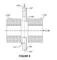
- FIG. 8shows a simplified block diagram of some embodiments of the system shown in FIGS. 1A-1D , including a section view of the main magnets shown in FIGS. 1C and 1D ;
- FIG. 9shows the Bz-field generated by the main MRI magnets as shielded according to some embodiments.
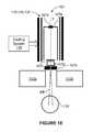
- FIG. 10shows a simplified block diagram of some embodiments of the system shown in FIGS. 1A-1D ;
- FIG. 11shows an embodiment of an active shield that can be used in some embodiments of the system shown in FIGS. 1A-1D ;
- FIGS. 12A-12Bshow the z-component of the magnetic field generated by the main MRI magnets before and after, respectively, activation of the active coil shown in FIG. 11 .
- FIGS. 1A-1Eshow various views of a split-magnet radiation therapy system 100 .
- FIGS. 1A and 1Bshow plan and perspective views, respectively, of a split-magnet radiation therapy system 100 .
- the system 100includes an integrated linear accelerator 107 and MRI system 102 , and allows for simultaneous irradiation from the linear accelerator 107 and imaging from the MRI 102 .
- the MRI 102can be used to pinpoint the location of an object to be irradiated, and this information can be used to control the irradiation from the linear accelerator 107 .
- the present disclosureis not necessarily limited to the specific MRI and linac systems shown in the Figures and referenced herein, but can apply equally to other MRI and linac systems.
- RF and/or magnetic shielding systems and methods disclosed hereincan be used with known MRI and linac systems that may differ from those shown in the Figures and described below.
- the radiation therapy system 100includes an open split solenoidal magnetic resonance imaging (MRI) device 102 , a radiation source 104 , a gantry 106 for housing a linac 107 and for changing the angle of radiation source 104 , a patient couch 108 , and a patient 110 in position for imaging and treatment.
- MRImagnetic resonance imaging
- a similar systemis described in U.S. Patent Application Publication 2005/0197564 to Dempsey, titled “System for Delivering Conformal Radiation Therapy while Simultaneously Imaging Soft Tissue” (hereinafter “Dempsey '564”), which is hereby incorporated by reference.
- the radiation therapy system 100 of the present disclosurediffers in many respects from that disclosed in Dempsey '564, a primary difference being that the radiation therapy system 100 of the present disclosure includes a linac 107 rather than the isotopic radiation system disclosed in Dempsey '564. Except as described herein, the linac 107 can be of conventional design. In some embodiments, the linac 107 , best shown in FIG. 1E , can be a medical grade or clinical linac (clinac) configured to accelerate electrons using a tuned-cavity waveguide 107 a in which the Radio frequency (RF) power creates a standing or traveling wave for the generation of high energy electrons from an electron gun 107 b .
- RFRadio frequency
- An optional target 107 ccan be included that is installed for x-ray/photon-beam therapy and removed for electron-beam therapy.
- the X-ray/photon beams and electron beamsconstitute examples of linac radiation beams.
- the system 100can include a pre-collimator 107 d and a multi-leaf collimator 107 e , for example as disclosed in Dempsey '564, for the electron beam EB from the linac 107 .
- the linac 107particularly the waveguide 107 a , can be protected by magnetic and/or RF shielding 118 , 120 , and/or 122 .
- the magnetic and/or RF shielding 118 , 120 , and/or 122can be in the form of one or more shells that are preferrably cylindrical, but other shapes can be used.
- the radiation therapy system 100can include a cooling system 115 for cooling the shielding 118 , 120 , and/or 122 .
- the cooling system 115can include, for example, liquid and/or air cooling systems.
- the radiation therapy system 100can include a split magnet system, such as described in Dempsey '564.
- the split magnet systemincludes a pair of main magnets 112 a and 112 b as shown in FIG. 1C as part of the MRI device 102 .
- the MRI device 102can also include conventional MRI components that are not shown, such as a split gradient coil, one or more shim coils (also referred to as shims), and an RF system, including RF coils.
- the strength of the magnetic field generated by the main magnets 112 a and 112 bcan vary.
- the system 100will be described with reference to an embodiment where the main magnet field strength is 0.35 T, which is chosen to prevent perturbations in the dose distribution caused by the Lorentz force acting on secondary electrons in the patient.
- the magnets 112 a and 112 bare separated by a central gap 114 , for example of 0.28 m.
- the MRI device 102can be designed to provide an MRI field-of-view of, for example, 50 cm diameter around a center of the image field, and at the same time provide an un-attenuated radiation beam in the gap 114 with the split gradient coil of the MRI device 102 .
- the system 100is constructed such that the radiation beam from the split gradient coil only passes through RF coils, the patient 110 , and the patient couch 108 .
- FIGS. 1C and 1Dshow a simplified block diagrams of the system 100 .
- FIG. 1Conly the main magnets 112 a and 112 b of the MRI system 102 are illustrated; in FIG. 1D only the main magnets 112 a and 112 b and the linac 107 are illustrated.
- the coordinate system shown in FIGS. 1C and 1Drefers to the longitudinal axis through the MRI bore (lengthwise through patient 110 ) as the Z-axis.
- the Z-axisis normal to a central axial plane CP, also referred to as transverse or central plane CP, which is at least substantially centered within the gap 114 between the main magnets 112 a and 112 b .
- the main magnets 112 a and 112 bboth extend radially about the Z-axis.
- the central plane CPis also defined by an X-axis and a Y-axis.
- the X-axisextends perpendicular to the Z-axis and from side to side of the MRI system 102 ;
- the Y-axisextends perpendicular to the Z-axis and from bottom to top of the MRI system 102 .
- the magnet field at 1 m from isocenterat a distance of 1 m from magnet isocenter IC on the central plane CP, there is a magnetic field of Bz ⁇ 0.1 T, shown as point P1, which is a desired distance from isocenter for the source of the radiation of the linac 107 .
- the magnetic fieldreverses direction from +Bz to ⁇ Bz at a radial distance of 0.81 m, shown as point P2.
- the magnet field at 1 m from isocenter, where the linac 107 radiation source is preferrably located for optimal radiotherapy operationis low enough that it can be contained in a ferromagnetic shield or multiple layered shields, as described below.
- the central axial plane CPthere is mainly axial magnetic field Bz because of coil symmetry.
- Yis a vertical axis and the axis of a high magnetic susceptibility (and/or permeability in a linear domain) material, e.g., a non-oriented silicon-steel shell, for shielding the linac 107 .
- a high magnetic susceptibility (and/or permeability in a linear domain) materiale.g., a non-oriented silicon-steel shell
- FIG. 2AThe field generated by the main magnets 112 a and 112 b near the central plane CP is shown in FIG. 2A .
- the linac 107has a longitudinal axis p that is aligned with the Y-axis in FIG. 1D . While the linac 107 is shown and described as being aligned along the Y-axis, it is preferable for the linac 107 to be rotatable about the Z-axis.
- the gantry 106 shown in FIGS. 1A and 1Bcan support the linac 107 and carry the linac 107 about the Z-axis (while the longitudinal axis p remains in the central plane CP), in the rotation directions RD shown in FIG.
- the linac 107can emit an electron beam EB towards the isocenter IC from any, or a range of, rotational positions about the Z-axis.
- the gantry 106 and linac 107can rotate about the Z-axis independently of other components of the system 100 .
- the gantry 106 and linac 107can rotate independently of the MRI 102 .
- FIGS. 3A-3B and FIGS. 4A-4Bwe now describe a general method for magnetically shielding the linac 107 from the magnetic field of the MRI system 102 .
- a magnetic shield or shell 118made of high magnetic susceptibility and permeability material, is placed around the linac accelerating structure 107 .
- the shell 118can be cylindrical in shape and aligned along axis p of the linac 107 , with one or both ends of the shell 118 being open. While a cylindrical shape is preferred, the disclosed shield shells can be other shapes.
- the magnetic shield 118can have a thickness chosen according to characteristics of the shell material.
- the magnetic shield 118(as well as other magnetic shields disclosed herein) can be formed of non-oriented silicon steel, for example a nickel-iron alloy, such as commercially-available material sold by ThyssenKrupp Steel under the trade name 530-50 AP and having a thickness of, for example, about be 5 mm.
- the B-H curve and relative permeability of “530-50AP” materialare shown in FIGS. 3A and 3B , respectively.
- Other material options for the magnetic shield 118include M19 steel, M45 steel, and Carpenter High Permeability “49” Steel.
- the magnets 112 a and 112 b , and the location of the magnetic shield 118 ,are illustrated in FIG. 4A , while a close-up perspective view of the magnetic shield 118 and linac 107 are shown in FIG. 4B .
- the outer diameter OD and length L of the magnetic shield 118can vary; in the present embodiment, the outer diameter OD is about 30 cm, and the length L is about 70 cm.
- a bottom edge 118 A of the magnetic shield 118is located at a fixed distance from the isocenter IC (in the present embodiment, about 80 cm) that is at or near the Bz field reversal location, although this is not a requirement.
- the location and size of the magnetic shield 118should be large enough to contain the linac 107 , but not so long or narrow that it limits the size of the beam emitted by the linac 107 .
- the magnetic shield 118 configurationis optimal for radiotherapy applications when combined with split main magnets 112 a and 112 b and gradient coil set, as the magnetic shield 118 is not imposed between the radiation source of the linac 107 and the patient 110 . This allows for producing radiotherapy beams of the linac 107 of high quality and strength.
- the magnetic shieldingcan be provided by multiple shield shells.
- the magnetic shieldingis provided by the magnetic shield 118 and a second magnetic shield 120 , where the shields 118 and 120 can be concentric layers of steel, which can be separated by layers of air or other insulating material.
- FIG. 5Ashows a comparison of the Bz-field generated by the main magnets 112 a and 112 b , and the z-component of the Bz-field generated by the main magnets 112 a and 112 b as shielded by an embodiment where the magnetic shielding comprises an outer magnetic shield 118 and an inner magnetic shield 120 , where the shields 118 and 120 are separated by a layer of air.
- FIG. 5Bshows a close-up view of FIG.
- Table 1lists the materials and dimensions of the magnetic shields 118 and 120 according to the embodiment associated with FIGS. 5A and 5B .
- IDis the inner diameter
- ODis the outer diameter
- Lengthis the shell length L
- Starting Y-positionis the distance from the isocenter (Z-axis) to the respective bottom edges of the shields 118 and 120 .
- the residual magnetic field along the axis of a single 5 mm thick shellis about 4.5 G, approximately ten times greater that the earth's magnetic field and larger than optimal for the linac 107 .
- the secondary shielding element 120can be a second shell 120 positioned inside of the first shell 118 , where both shells are coaxial along the longitudinal axis ⁇ of the linac 107 .
- the second shell 120can be of higher permeability, but of a lower saturation flux density of the outer shell 118 , as the outer shell 118 has greatly reduced the magnetic field, e.g., mu-metal. It is preferable to magnetically isolate the shells 118 and 120 in order to gain the highest shielding by restarting the saturation of the metal.
- the secondary shielding element 120can be a current carrying coil that is located inside of the primary shell 118 to cancel the residual field. If the magnetic field remaining is sufficiently low and its value and direction in space are known, then it can be possible to make small adjustments in the accelerating portion of the linac
- the current linacsare configured to accommodate an electron beam that is at least substantially straight; if the beam were bent only a small amount by the field, the anticipated beam path can be calculated and the accelerating plates can be altered to accommodate the beam bending. Given the azimuthally symmetric nature of the fringe field, the path deviation of the electron beam should be largely independent of gantry position.
- the secondary shielding element 120can be an RF shield 120 , as further described below.
- the peak-to-peak field in-homogeneity of the system main magnets 112 a and 112 b plus the double shellis 623.8 ppm over 45 cm DSV. This inhomogeneity is too large for MRI system 102 , so additional shimming is desirable.
- the field inhomogeneityis mostly represented by a few of the tesseral harmonics; S 1,1 ⁇ Y, C 2,2 ⁇ (X2-Y2), and S 3,1 ⁇ Z2X, and S 3,3 ⁇ X3. All of the major harmonics of significance are listed in Table 2.
- the zonal harmonicscan all be handled by shimming, and the shim setting does not change with rotation of the linac 107 around the Z-axis. Hence, the shims can be located on the MRI bore.
- the negative of the zonal harmonicscould even be built into the magnets 112 a and 112 b so that the combination of magnets 112 a , 112 b plus magnetic shield 118 eliminates these terms.
- the tesseral harmonicsare a larger problem because they would move with the linac orientation.
- the tesseral harmonicscould be shimmed out with passive shims near the central plane CP on the gantry 106 that would move with the gantry 106 /linac 107 rotation and/or with resistive shims built into the gradient coil that could be electrically adjusted to match the rotation of the gantry 106 .
- the system 100 as shown in FIGS. 1A-1Dincludes a linac 107 having a vertical acceleration axis and is mounted on the gantry 106 so that the linac 107 can be rotated about the radiotherapy and MRI 102 isocenters.
- the linac 107is also preferred to be of low energy, in the range of 4 to 6 MV, and have a standing wave guide to keep it compact.
- the linac 107can be configured to only produce photon beams that can be used for intensity modulated radiation therapy or conformal radiation therapy.
- the linac 107can operate at either S-band or X-Band frequencies, but S-band is preferred for high output and stability. Referring to FIG.
- the element 120can be configured to serve as an RF shield 120 .
- the RF shield shell 120can be made of a suitable shielding material, for example copper foil, aluminum foil, or carbon fiber.
- a suitable shielding materialfor example copper foil, aluminum foil, or carbon fiber.
- Metals such as copper and aluminumtend to reflect RF radiation due to eddy currents on their surfaces.
- the carbon fiber materialstend to absorb RF energy.
- the eddy currentscan be reduced by providing one or more slots that extend through the shield shell.
- shield shell 120is shown as having slots 120 A and 120 B in FIG. 4C .
- the size, number, and configuration of the slotscan vary from that shown in FIG. 4C .
- shield shell 120is shown with slots, such slots can also, or alternatively, be provided in shield shell 118 ; also, any number of such slots can be provided in any one or more of the shield shells in embodiments having more than one shield shell.
- Such slotscan also be desirable in the magnetic shielding shells, and can thus be included in some embodiments of the magnetic shielding shells.
- FIG. 4Cshows two layers (shield shells 120 and 118 ), alternative embodiments can include any number of layers.
- the layers of shield shellscan be made of combinations of different materials or of the same material.
- the shield shell layerscan include alternating layers formed of RF absorbing material and RF reflecting material. In such embodiments, it is desirable to provide an air gap between the layers of shield shells.
- Coolingcan be provided by cooling system 115 ( FIG. 1E ) as needed to the absorbing material in the RF shield 120 .
- a variety of known cooling methodscan be used for cooling the RF shield 120 .
- the cooling system 115can include, for example, fluid-carrying conduit for circulating a fluid in the vicinity of one or more of the shield shells that form the RF shield 120 .
- air-coolingcan be provided by incorporating a system for moving air across one or more surfaces of the shield shells that form the RF shield 120 .
- the magnetic shield 118 and the RF shield 120are placed around the linac 107 to shield the path of the electrons from the electron gun 107 b of the linac 107 to the target to a magnetic field strength on the order of the size of the earth's magnetic field strength.
- the magnetic shield 118is arranged such that it is not in the path of the radiotherapy beam, for example as shown in FIGS. 4A and 4C .
- the RF shield 120is also placed around the linac 107 , rather than the MRI 102 , and comprised of both absorptive and reflective layers to dissipate and absorb the RF radiation generated by the linac 107 before it can compromise the MRI function and they can function as part of the flattening filter.
- the RF shield 120can work in concert with a standard bore-mounted MRI RF shield.
- the beam from the linac 107is allowed to pass through the RF shield 120 (as well as the bore mounted MRI RF shield in such embodiments) as long as the RF shield(s) are uniformly and minimally attenuating to the radiotherapy beam.
- the RF shield 120can be provided without the magnetic shield 118 where only the RF shielding may be desired.
- the secondary shielding element 120 shown in FIG. 4Ccan be a second magnetic shield 120 .
- a magnetic shield device 122can include one or more concentric magnetic shields, which can include magnetic shields 118 and 120 as well as one or more additional magnetic shields.
- the magnetic shield device 122can include the multiple magnetic shields, including shields 118 and 120 , that are made of high magnetic susceptibility (and permeability) material.
- the shields of the magnetic shield device 122can be concentrically placed inside of each other around the linac 107 accelerating structure.
- the magnetic shields of the magnetic shield device 122can be magnetically and electrically isolated from each other with a suitable dielectric material such as air or plastic. Having multiple magnetic shields is beneficial because the magnetic field shielding of the material begins to saturate with depth. Introducing a new magnetic shield restarts the saturation effect providing increased shielding. Also, some embodiments such as the one shown in FIG. 4E can include a linac 107 having a split radiotherapy magnets 126 and 128 and a magnetic shield made of two isolated shells 130 and 132 . The thickness of the magnetic shields of the embodiments shown in FIGS. 4A-4E can be chosen to be, for example, 5 mm, and the material can be selected to be 530-50AP steel material.
- the magnetic shield 118(as well as other magnetic shields disclosed herein) include M19 steel, M45 steel, and steel sold by ThyssenKrupp Steel under the trade name 530-50 AP.
- the outer diameter OD and length L of the shielding shellscan be, for example, 27 cm and 30 cm, respectively, in a two-shell embodiment such as the one shown in FIG. 4C .
- the shells 118 and 120can both be located at a fixed distance from the isocenter IC (in the present embodiment, about 85 cm) that is at or near the Bz field reversal location, although this is not a requirement.
- the location and size of the magnetic shieldsshould be large enough to contain the linac 107 , but not so long or narrow that it limits the size of the beam from the linac 107 .
- FIG. 6Ashows a comparison of the Bz-field generated by the main magnets 112 a and 112 b , and the z-component of the Bz-field generated by the magnets 112 a and 112 b as shielded using a magnetic shield device 122 that includes three concentric shield shells.
- Table 3lists the materials and dimensions of the magnetic shield device 122 according to the embodiments associated with FIGS. 6A and 6B . In the embodiment associated with FIGS.
- the magnetic shield device 122includes three concentric shells separated from each other by layers of air.
- the shells of the shield deviceare preferrably cylindrical, but can be other shapes.
- IDis the inner diameter
- ODis the outer diameter
- Lengthis the shell length L
- Starting Y-positionis the distance from the isocenter (Z-axis) to the respective bottom edges of the layers of the shield device 122 .
- the residual B-fieldis less than 1 Gauss in the region 1100 mm ⁇ y ⁇ 1400 mm. This is roughly comparable to the earth's field close to the axis p.
- the harmonics of the magnetic fieldare close to the single shell model associated with the embodiment shown in FIG. 4B .
- the Peak-to-Peak field in-homogeneity over 45 cm DSV generated by the main magnets 112 a and 112 b plus the magnetic shields 118 and 120is 623.6 ppm. It is preferable to have the best shielding on the electron gun 107 b of the linac 107 and less shielding can be applied to the target end of the accelerating structure. This field in-homogeneity is mostly represented by the y-harmonic.
- the spherical harmonicsare listed in Table 4.
- FIG. 8another embodiment will be described that can reduce field in-homogeneity caused by the presence of a linac shield, such as the shield 118 shown in FIGS. 4A and 4B .
- the embodiment shown in FIG. 8can be similar to the embodiment shown in FIGS. 4A and 4B , and like components have retained the same element numbers; description of those components applies equally here, so the description is not repeated.
- FIG. 8In the embodiment shown in FIG.
- the first shield 118extends along a first longitudinal axis ⁇ 1 and a second shield 140 (which can optionally include a second linac 107 ′) extends along a second longitudinal axis ⁇ 2 symmetrically 180° apart from the first longitudinal axis ⁇ 1 of the first magnetic shield 118 .
- Each of the axes ⁇ 1 and ⁇ 2is on the central plane CP.
- the second shield 140can be formed of a magnetically shielding material, such as steel sold by ThyssenKrupp Steel under the trade name 530-50 AP, as described in connection with magnetic shield 118 .
- magnétique shield 118examples include M19 steel, M45 steel, and Carpenter 49 steel. If only a second symmetric shield 140 is present, this solution can be thought of as a symmetric shim for the primary shell 118 .
- the magnetic shields 118 and 140can be magnetic shield devices that include two or more concentric magnetic shield shells, such as shown in FIG. 4C or FIG. 4D .
- FIG. 9shows the Bz-field generated by the main magnets 112 a and 112 b and in an embodiment where both the magnetic shield 118 and the magnetic shield 140 include two concentric magnetic shielding shells.
- the peak-to-peak field in-homogeneity over 45 cm DSV generated by the system main magnets 112 a and 112 b plus the two double-shell shield ( 118 + 140 )is 416.96 ppm.
- This field in-homogeneityis mostly generated by the Z2 harmonic.
- the Y-harmonicsall become negligible small because of the Y symmetry.
- the harmonics for this caseare listed in Table 4.
- the zonal harmonicsare now twice as large as in the single shell model associated with the embodiment shown in FIG. 4B . However, they can all be handled by passive shimming, and the shim setting does not change with rotation of the linac 107 around the Z-axis.
- the negative of the zonal harmonicscould even be built into the main magnets 112 a and 112 b so that the combination of main magnets 112 a and 112 b plus shield shells 118 and 140 eliminates these terms.
- the Tesseral harmonicsare a larger problem because they would move with the linac 107 rotational position. However, symmetry eliminates the worst of the harmonics.
- the Tesseral harmonicscan be shimmed out with passive shims near the central plane on the linac gantry 106 and/or with resistive electrical shims.
- Passive shims built into the rotating gantry 106can be permanent magnet shims at these magnetic field levels (oriented magnetization shims for more shim options).
- Passive shimscan be added at a smaller radius to reduce the material required in the shims. Resistive electrical shims in the gradient would change with the rotation of the linac gantry.
- Such embodimentscan be arranged in a manner similar to the embodiment shown in FIG. 8 .
- the magnetic shield shellstend to act as RF shields, multiple shells are advantageous for providing RF shielding.
- annulus discs 144 and 146there can be two parallel annulus discs 144 and 146 made of high relative permeability material. They can be a part of the gantry 106 and on opposing sides of the linac 107 .
- the Tesseral spherical harmonicsshould be relatively small, and the Zonal harmonics should be relatively big. Placing two annulus discs 144 and 146 in some sense are equivalent to two extra coils in the main magnet 112 a , 112 b .
- the main magnet 112 a , 112 bcan be designed to accommodate two annulus discs 144 and 146 .
- the magnetic field from the main magnets 112 a and 112 b at 1 meter from isocenter along the Y-axisis difficult to shield without the field reduction of passive shields, such as shield 118 described above.
- the residual fieldis near 5-7 Gauss.
- This residual fieldcan easily be shimmed out with DC current in a coil, for example in embodiments where the secondary shielding element 120 shown in FIG. 4C is a coil 120 ′.
- a schematic view of the shielding coil 120 ′is shown in FIG. 11 .
- the coil 120 ′can be cylindrical, having a half-length L and radius R and designed according to the following method (although shapes other than cylindrical can be used).
- the shielding coil 120 ′should preferrably produce the magnetic flux field Bx (in local system of coordinates) that cancels the Bz component of the magnetic field (in the original system of coordinates) generated by the main magnets 112 a and 112 b.
- a ⁇ ⁇ ( ⁇ , ⁇ , z )⁇ ⁇ ⁇ R 2 2 ⁇ ⁇ ⁇ ⁇ sin ⁇ ( ⁇ ) ⁇ ⁇ 0 ⁇ ⁇ k ⁇ ⁇ d k ⁇ ( T 2 ⁇ ( k , ⁇ , R ) - T 0 ⁇ ( k , ⁇ , R ) ) ⁇ F S ⁇ ( k , z )
- a ⁇ ⁇ ( ⁇ , ⁇ , z )- ⁇ ⁇ ⁇ R 2 2 ⁇ ⁇ ⁇ ⁇ cos ⁇ ( ⁇ ) ⁇ 0 ⁇ ⁇ k ⁇ d k ⁇ ( T 2 ⁇ ( k , ⁇ , R ) + T 0 ⁇ ( k , ⁇ , R ) ) ⁇ F S ⁇ ( k , z ) ⁇ A Z ⁇ ( ⁇ , ⁇ ,
- I n (k ⁇ ), K n (k ⁇ )are modified Bessel functions.
- the transverse components of the magnetic fieldcan be presented in the following form:
- the Bx-component of the magnetic flux field inside the cylinder of the coil 120 ′is:
- Eis the energy of the coil 120 ′
- the second termis to minimize the deviation of the field produced by the shielding coil 120 ′ from that of the main magnets 112 a , 112 b
- the third termis to minimize the effect of the shield coil 120 ′ on the field in-homogeneity in the imaging volume
- the last termis introduced as to limit the current density.
- the coefficients ⁇ , ⁇ , and ⁇are the weighting factors; ⁇ can be a regularization parameter to minimize the current in the shielding coil 120 ′.
- the current density f Z (z)can be expressed in terms of a basis functions. It should be mentioned that the current density f Z (z) is zero at the ends of the shielding coil 120 ′.
- the energy Ehas the following form:
- the field produced by the shield coil 120 ′has the following form:
- Some embodimentscan include a combined passive shield and active coil.
- the residual Bz-field shown in FIG. 5 b(a single shell case) was used as an input data.
- FIG. 12Ashows the z-component of the current density on the active shield coil 120 ′ prior to activation (i.e., prior to application of an electric current) of the coil 120 ′
- FIG. 12Bshows the residual Bz-field after activation of the shield coil 120 ′.
- the parameter ⁇ that accounts for the effect of correcting the in-homogeneity inside the DSVwas chosen to be zero because the level of the residual field of FIG. 5B is already small (of the order of 7 Gauss) and the active shield coil is located far from the imaging volume.
- Some embodimentscan include a completely active coil shielding system.
- the shielding of the linac 107can be accomplished locally using only the above-described active current-carrying coils, such as coil 120 ′, in place of the passive magnetic shields in embodiments described above.
- the coils 120 ′can be arranged to simply cancel the field at the linac 107 and can also incorporate an active shield to reduce the influence on the homogeneity of the main magnetic field.
- Still another alternative way of shielding the linac 107 locallyis to use a distribution of permanent magnets. They can be arranged to simply cancel the field at the linac 107 and can also incorporate an active shield, such as coil 120 ′, to reduce the influence on the homogeneity of the main magnetic field from the main magnets 112 a and 112 b.
- the magnetic shields described hereinsuch as shields 118 , 120 , 122 , 130 , 132 , and others experience a force from the main magnets 112 a and 112 b of the MRI 102 .
- the mounting for the shieldsis preferably designed to withstand such magnetic forces.
- the high-power RF source and waveguide for the linac 107can also be enclosed, or partially enclosed, within the magnetic shields disclosed herein.
- the RF shieldingcan be extended to contain some or all components of the linac 107 .
- clinical linacs suitable for use as linac 107can operate in the S-band frequency range accelerate electrons to about 6 MeV using RF microwave cavities at ⁇ 3 GHz. While this frequency is well above the 15 MHz of the MRI system 102 , it involves megawatts of RF power pulse with a frequency of several hundred Hertz. Sidebands in the RF power source can excite/reflect from other materials causing interference with the operation of the MRI system 102 .
- the element 120can be an RF shield that is placed around the linac 107 made of RF absorbing, RF reflecting, or a combination of both can effectively eliminate the RF interference with the MRI system 102 .
- the MRI RF roomwhich can be made of RF reflecting material that can bound RF from the linac 107 into the MRI 102 , can be lined on the interior surface with a wall covering of RF absorbing material, e.g., meshed or chopped carbon fiber, carbon fiber wallpaper, carbon fiber panels, or carbon fiber paint, and eliminate RF reaching the MRI.
- the gantry 106 and area around the RF source of the linac 107can be covered in RF absorbers, reflectors, and combinations of both to reduce the ambient (environmental) RF fields.
- the RFwill produce dielectric heating of polarized molecules such as water.
- a variety of polarized molecule materialscan be used as RF absorber for the RF energy.
- some of the conductive surfaces that divert RF energy in a closed systemare missing in the magnet gap 114 .
- An RF shield about the MRI borecan be used in conjunction with the other shielding method described above.
- the RF shieldsdo not add significantly to the beam attenuation so that the quality of the radiotherapy is significantly compromised.
- the conductive shieldingmay or may not be grounded to the magnet. If these surfaces were made of aluminum, such as aluminum foil, the beam attenuation would even be less than using copper. If the gradient coil is wound on a former one can construct the former out of carbon fiber for isolation from the linac system.
Landscapes
- Physics & Mathematics (AREA)
- Health & Medical Sciences (AREA)
- Engineering & Computer Science (AREA)
- Condensed Matter Physics & Semiconductors (AREA)
- General Physics & Mathematics (AREA)
- Biomedical Technology (AREA)
- Nuclear Medicine, Radiotherapy & Molecular Imaging (AREA)
- Radiology & Medical Imaging (AREA)
- General Health & Medical Sciences (AREA)
- Life Sciences & Earth Sciences (AREA)
- Veterinary Medicine (AREA)
- Animal Behavior & Ethology (AREA)
- Public Health (AREA)
- Pathology (AREA)
- Epidemiology (AREA)
- High Energy & Nuclear Physics (AREA)
- Pulmonology (AREA)
- Theoretical Computer Science (AREA)
- Biophysics (AREA)
- Surgery (AREA)
- Molecular Biology (AREA)
- Medical Informatics (AREA)
- Heart & Thoracic Surgery (AREA)
- Radiation-Therapy Devices (AREA)
- Magnetic Resonance Imaging Apparatus (AREA)
- Particle Accelerators (AREA)
Abstract
Description
| TABLE 1 |
| Two Shells of 530-50AP Steel |
| Layer | ID [mm] | OD [mm] | Length [mm] | Starting Y-position [mm] |
| Inner | 260.0 | 270.0 | 700.0 | 900.0 |
| Outer | 280.0 | 300.0 | 700.0 | 900.0 |
| TABLE 2 |
| Spherical Harmonics over 45 cm DSV |
| Zonal Harmonics | |
| [ppm] | Tesseral harmonics [ppm] |
| n | Cn | n | m | Cn,m | Sn,m |
| 1 | 1.625035E−03 | 1 | 1 | 6.6950990E−03 | −2.6417408E+02 |
| 2 | −9.190121E+01 | 2 | 1 | −4.3762731E−03 | −2.2226838E−03 |
| 3 | 4.274773E−03 | 2 | 2 | −2.3791910E+01 | −1.1871930E−03 |
| 4 | 8.878808E+00 | 3 | 1 | −1.1657569E−04 | 1.5830479E+01 |
| 5 | −2.132553E−03 | 3 | 2 | −1.9884826E−04 | 5.8882723E−04 |
| 6 | −6.259163E−01 | 3 | 3 | −1.0577878E−04 | 1.2089904E+00 |
| 7 | −7.645843E−03 | 4 | 1 | 3.2428894E−04 | −2.8578203E−05 |
| 8 | 3.513474E−01 | 4 | 2 | 8.1373300E−01 | 3.6183409E−05 |
| 9 | −9.504502E−03 | 4 | 3 | 7.2001599E−05 | 3.3853550E−05 |
| 10 | 2.238179E+00 | 4 | 4 | 4.2607165E−02 | −5.3185952E−06 |
| 11 | 6.139678E−03 | 5 | 1 | −2.7178914E−04 | −9.0437945E−01 |
| TABLE 3 |
| Steel M19 and Two Shells of 530-50AP Steel |
| Starting Y- | |||||
| OD | Length | position | |||
| Layer | Material | ID [mm] | [mm] | [mm] | [mm] |
| Inner | “M19” Steel | 244.0 | 254.0 | 700.0 | 900.0 |
| Middle | “530-50AP” Steel | 260.0 | 270.0 | 700.0 | 900.0 |
| Outer | “530-50AP” Steel | 280.0 | 300.0 | 700.0 | 900.0 |
| TABLE 4 |
| Two shells solution: Spherical Harmonics over 45 cm DSV |
| Zonal Harmonics | |
| [ppm] | Tesseral harmonics [ppm] |
| n | Cn | n | m | Cn,m | Sn,m |
| 1 | 1.6250352E−03 | 1 | 1 | 6.6950990E−03 | −2.6417408E+02 |
| 2 | −9.1901212E+01 | 2 | 1 | −4.3762731E−03 | −2.2226838E−03 |
| 3 | 4.2747730E−03 | 2 | 2 | −2.3791910E+01 | −1.1871930E−03 |
| 4 | 8.8788081E+00 | 3 | 1 | −1.1657569E−04 | 1.5830479E+01 |
| 5 | −2.1325528E−03 | 3 | 2 | −1.9884826E−04 | 5.8882723E−04 |
| 6 | −6.2591632E−01 | 3 | 3 | −1.0577878E−04 | 1.2089904E+00 |
| 7 | −7.6458435E−03 | 4 | 1 | 3.2428894E−04 | −2.8578203E−05 |
| 8 | 3.5134737E−01 | 4 | 2 | 8.1373300E−01 | 3.6183409E−05 |
| 9 | −9.5045015E−03 | 4 | 3 | 7.2001599E−05 | 3.3853550E−05 |
| 10 | 2.2381795E+00 | 4 | 4 | 4.2607165E−02 | −5.3185952E−06 |
| 11 | 6.1396783E−03 | 5 | 1 | −2.7178914E−04 | −9.0437945E−01 |
| TABLE 4 |
| Two double shells solution: Spherical Harmonics over 45 cm DSV |
| Zonal Harmonics | |
| [ppm] | Tesseral Harmonics [ppm] |
| n | Cn | n | m | Cn,m | Sn,m |
| 1 | −1.1158532E−03 | 1 | 1 | −1.3130497E−04 | −1.3130497E−04 |
| 2 | −1.7798728E+02 | 2 | 1 | 9.4937074E−05 | 9.4937074E−05 |
| 3 | 7.9200018E−03 | 2 | 2 | −4.7129252E+01 | −9.2290614E−03 |
| 4 | 1.7600141E+01 | 3 | 1 | 4.5203733E−06 | 4.5203734E−06 |
| 5 | −2.2793685E−03 | 3 | 2 | −4.0735120E−05 | −8.2531950E−04 |
| 6 | −1.3166284E+00 | 3 | 3 | 1.0363288E−05 | −1.0363288E−05 |
| 7 | −1.3414318E−02 | 4 | 1 | −7.1884515E−05 | −7.1884515E−05 |
| 8 | 4.0916507E−01 | 4 | 2 | 1.6230890E+00 | 2.4395720E−04 |
| 9 | −1.8969599E−02 | 4 | 3 | −5.7802678E−06 | 5.7802678E−06 |
| 10 | 2.2510390E+00 | 4 | 4 | 8.3827275E−02 | 1.3021016E−05 |
| 11 | 1.0428939E−02 | 5 | 1 | 5.3620187E−05 | 5.3620187E−05 |
{right arrow over (J)}(ρ,φ,z)=δ(ρ−R){êφfφ(z)cos(φ)+êZfZ(z)sin(φ)}∇{right arrow over (J)}=0

- 100 Radiation therapy system
- 102 MRI device
- 104 Radiation source
- 106 Gantry
- 107 Linear accelerator
- 108 Patient couch
- 107aWaveguide
- 107bElectron gun
- 107cTarget
- 107dPre-collimator
- 107eMulti-leaf collimator
- 107′ Second linear accelerator
- 110 Patient
- 112aMain magnet
- 112bMain magnet
- 114 Central gap
- 115 Cooling system
- 118 Outer magnetic shield
- 118aBottom edge
- 120 Inner magnetic shield
- 120′ Shielding coil
- EB Electron beam
- CP Central axial plane
- IC Isocenter
- P1 Point
- P2 Point
- RD Rotation directions
- 120A Slot
- 120B Slot
- 122 Magnetic shield device
- 126 Split radiotherapy magnet
- 128 Split radiotherapy magnet
- 130 Isolated shell
- 132 Isolated shell
- 140 Second shield
- 144 Annulus disc
- 146 Annulus disc
Claims (20)
Priority Applications (5)
| Application Number | Priority Date | Filing Date | Title |
|---|---|---|---|
| US14/481,619US9421398B2 (en) | 2009-07-15 | 2014-09-09 | Method and apparatus for shielding a linear accelerator and a magnetic resonance imaging device from each other |
| US15/242,449US10463883B2 (en) | 2009-07-15 | 2016-08-19 | Method and apparatus for shielding a linear accelerator and a magnetic resonance imaging device from each other |
| US16/362,094US10918887B2 (en) | 2009-07-15 | 2019-03-22 | Method and apparatus for shielding a linear accelerator and a magnetic resonance imaging device from each other |
| US17/174,116US11452463B2 (en) | 2009-07-15 | 2021-02-11 | Method and apparatus for shielding a linear accelerator and a magnetic resonance imaging device from each other |
| US17/948,428US12105166B2 (en) | 2009-07-15 | 2022-09-20 | Method and apparatus for shielding a linear accelerator and a magnetic resonance imaging device from each other |
Applications Claiming Priority (3)
| Application Number | Priority Date | Filing Date | Title |
|---|---|---|---|
| US22577109P | 2009-07-15 | 2009-07-15 | |
| US12/837,309US8836332B2 (en) | 2009-07-15 | 2010-07-15 | Method and apparatus for shielding a linear accelerator and a magnetic resonance imaging device from each other |
| US14/481,619US9421398B2 (en) | 2009-07-15 | 2014-09-09 | Method and apparatus for shielding a linear accelerator and a magnetic resonance imaging device from each other |
Related Parent Applications (1)
| Application Number | Title | Priority Date | Filing Date |
|---|---|---|---|
| US12/837,309ContinuationUS8836332B2 (en) | 2009-07-15 | 2010-07-15 | Method and apparatus for shielding a linear accelerator and a magnetic resonance imaging device from each other |
Related Child Applications (1)
| Application Number | Title | Priority Date | Filing Date |
|---|---|---|---|
| US15/242,449ContinuationUS10463883B2 (en) | 2009-07-15 | 2016-08-19 | Method and apparatus for shielding a linear accelerator and a magnetic resonance imaging device from each other |
Publications (2)
| Publication Number | Publication Date |
|---|---|
| US20150065860A1 US20150065860A1 (en) | 2015-03-05 |
| US9421398B2true US9421398B2 (en) | 2016-08-23 |
Family
ID=43449796
Family Applications (6)
| Application Number | Title | Priority Date | Filing Date |
|---|---|---|---|
| US12/837,309Expired - Fee RelatedUS8836332B2 (en) | 2009-07-15 | 2010-07-15 | Method and apparatus for shielding a linear accelerator and a magnetic resonance imaging device from each other |
| US14/481,619ActiveUS9421398B2 (en) | 2009-07-15 | 2014-09-09 | Method and apparatus for shielding a linear accelerator and a magnetic resonance imaging device from each other |
| US15/242,449Active2031-03-19US10463883B2 (en) | 2009-07-15 | 2016-08-19 | Method and apparatus for shielding a linear accelerator and a magnetic resonance imaging device from each other |
| US16/362,094Active2030-09-05US10918887B2 (en) | 2009-07-15 | 2019-03-22 | Method and apparatus for shielding a linear accelerator and a magnetic resonance imaging device from each other |
| US17/174,116ActiveUS11452463B2 (en) | 2009-07-15 | 2021-02-11 | Method and apparatus for shielding a linear accelerator and a magnetic resonance imaging device from each other |
| US17/948,428ActiveUS12105166B2 (en) | 2009-07-15 | 2022-09-20 | Method and apparatus for shielding a linear accelerator and a magnetic resonance imaging device from each other |
Family Applications Before (1)
| Application Number | Title | Priority Date | Filing Date |
|---|---|---|---|
| US12/837,309Expired - Fee RelatedUS8836332B2 (en) | 2009-07-15 | 2010-07-15 | Method and apparatus for shielding a linear accelerator and a magnetic resonance imaging device from each other |
Family Applications After (4)
| Application Number | Title | Priority Date | Filing Date |
|---|---|---|---|
| US15/242,449Active2031-03-19US10463883B2 (en) | 2009-07-15 | 2016-08-19 | Method and apparatus for shielding a linear accelerator and a magnetic resonance imaging device from each other |
| US16/362,094Active2030-09-05US10918887B2 (en) | 2009-07-15 | 2019-03-22 | Method and apparatus for shielding a linear accelerator and a magnetic resonance imaging device from each other |
| US17/174,116ActiveUS11452463B2 (en) | 2009-07-15 | 2021-02-11 | Method and apparatus for shielding a linear accelerator and a magnetic resonance imaging device from each other |
| US17/948,428ActiveUS12105166B2 (en) | 2009-07-15 | 2022-09-20 | Method and apparatus for shielding a linear accelerator and a magnetic resonance imaging device from each other |
Country Status (7)
| Country | Link |
|---|---|
| US (6) | US8836332B2 (en) |
| EP (1) | EP2454617B1 (en) |
| JP (6) | JP5719844B2 (en) |
| CN (3) | CN110201317B (en) |
| AU (4) | AU2010273298B2 (en) |
| CA (3) | CA3198109A1 (en) |
| WO (1) | WO2011008969A1 (en) |
Cited By (14)
| Publication number | Priority date | Publication date | Assignee | Title |
|---|---|---|---|---|
| US20170001039A1 (en)* | 2013-03-15 | 2017-01-05 | Viewray Technologies, Inc. | Systems and methods for linear accelerator radiotherapy with magnetic resonance imaging |
| US20170014644A1 (en)* | 2009-07-15 | 2017-01-19 | Viewray Technologies, Inc. | Method and appratus for shielding a linear accelerator and a magnetic resonance imaging device from each other |
| US9817096B2 (en)* | 2013-03-20 | 2017-11-14 | Bruker Biospin Ag | Actively shielded, cylindrical gradient coil system with passive RF shielding for NMR devices |
| US10688319B2 (en) | 2004-02-20 | 2020-06-23 | University Of Florida Research Foundation, Inc. | System for delivering conformal radiation therapy while simultaneously imaging soft tissue |
| US11000706B2 (en) | 2016-12-13 | 2021-05-11 | Viewray Technologies, Inc. | Radiation therapy systems and methods |
| US11033758B2 (en) | 2017-12-06 | 2021-06-15 | Viewray Technologies, Inc. | Radiotherapy systems, methods and software |
| US20210213305A1 (en)* | 2018-11-14 | 2021-07-15 | Shanghai United Imaging Healthcare Co., Ltd. | Radiation therapy system and method |
| US11209509B2 (en) | 2018-05-16 | 2021-12-28 | Viewray Technologies, Inc. | Resistive electromagnet systems and methods |
| US11351398B2 (en) | 2016-03-02 | 2022-06-07 | Viewray Technologies, Inc. | Particle therapy with magnetic resonance imaging |
| US11378629B2 (en) | 2016-06-22 | 2022-07-05 | Viewray Technologies, Inc. | Magnetic resonance imaging |
| US11633625B2 (en) | 2019-02-02 | 2023-04-25 | Shanghai United Imaging Healthcare Co., Ltd. | Radiation therapy system and method |
| US12090343B2 (en) | 2012-10-26 | 2024-09-17 | Viewray Systems, Inc. | Assessment and improvement of treatment using imaging of physiological responses to radiation therapy |
| US12245355B2 (en) | 2021-02-19 | 2025-03-04 | Mevion Medical Systems, Inc. | Gantry for a particle therapy system |
| US12296196B2 (en) | 2020-06-17 | 2025-05-13 | Shanghai United Imaging Healthcare Co., Ltd. | Radiation therapy system and method |
Families Citing this family (88)
| Publication number | Priority date | Publication date | Assignee | Title |
|---|---|---|---|---|
| CN102804207B (en)* | 2009-06-19 | 2016-08-03 | 微雷公司 | Systems and methods for performing tomographic image acquisition and reconstruction |
| DE102009038686B4 (en)* | 2009-08-24 | 2020-10-22 | Siemens Healthcare Gmbh | Whole-body coil arrangement for an open magnetic resonance device for use with a second diagnostic and / or therapeutic modality, magnetic resonance device and combination device |
| AU2010327289B2 (en)* | 2009-12-02 | 2015-05-28 | Nanalysis Corp. | Method and apparatus for producing homogeneous magnetic fields |
| CN102781311B (en) | 2010-02-24 | 2016-09-21 | 优瑞技术公司 | Split type magnetic resonance imaging system |
| WO2011127947A1 (en)* | 2010-04-15 | 2011-10-20 | Elekta Ab (Publ) | Radiotherapy and imaging apparatus |
| RU2591783C2 (en)* | 2010-12-08 | 2016-07-20 | Конинклейке Филипс Электроникс Н.В. | Unit of current-collecting ring |
| DE102011006582A1 (en) | 2011-03-31 | 2012-10-04 | Siemens Aktiengesellschaft | Radiation therapy system with high-frequency shielding |
| JP6139064B2 (en)* | 2011-05-10 | 2017-05-31 | 東芝メディカルシステムズ株式会社 | Magnetic resonance imaging apparatus and magnetic field adjustment tool for magnetic resonance imaging apparatus |
| JP6018185B2 (en)* | 2011-05-31 | 2016-11-02 | コーニンクレッカ フィリップス エヌ ヴェKoninklijke Philips N.V. | Static magnetic field correction of MRI radiation therapy equipment |
| US8981779B2 (en) | 2011-12-13 | 2015-03-17 | Viewray Incorporated | Active resistive shimming fro MRI devices |
| US10561861B2 (en) | 2012-05-02 | 2020-02-18 | Viewray Technologies, Inc. | Videographic display of real-time medical treatment |
| GB201217782D0 (en)* | 2012-10-04 | 2012-11-14 | Tesla Engineering Ltd | Magnet apparatus |
| GB2507585B (en) | 2012-11-06 | 2015-04-22 | Siemens Plc | MRI magnet for radiation and particle therapy |
| GB2507792B (en)* | 2012-11-12 | 2015-07-01 | Siemens Plc | Combined MRI and radiation therapy system |
| TW201421211A (en)* | 2012-11-16 | 2014-06-01 | Primax Electronics Ltd | Wireless charging device |
| KR101378447B1 (en) | 2012-11-19 | 2014-03-26 | 한국전기연구원 | Magnetic field shielding structure of mri based linac system |
| CN105051562B (en)* | 2013-02-06 | 2019-03-01 | 皇家飞利浦有限公司 | For the Active Compensation of the field distortion component in the magnetic resonance imaging system with rack |
| US9404983B2 (en)* | 2013-03-12 | 2016-08-02 | Viewray, Incorporated | Radio frequency transmit coil for magnetic resonance imaging system |
| US9289626B2 (en) | 2013-03-13 | 2016-03-22 | Viewray Incorporated | Systems and methods for improved radioisotopic dose calculation and delivery |
| US9675271B2 (en)* | 2013-03-13 | 2017-06-13 | Viewray Technologies, Inc. | Systems and methods for radiotherapy with magnetic resonance imaging |
| CN105324678B (en)* | 2013-06-21 | 2018-11-20 | 皇家飞利浦有限公司 | Shim system for MRI hybrid scanners |
| EP3011357B1 (en)* | 2013-06-21 | 2022-10-12 | Koninklijke Philips N.V. | Magnet assembly for combined magnetic resonance imaging and radiation therapy |
| KR101545171B1 (en) | 2013-09-23 | 2015-08-19 | 한국전기연구원 | Radiation therapy system using magnetic resonance imaging guided linear accelerator |
| JP6568077B2 (en)* | 2013-09-30 | 2019-08-28 | コーニンクレッカ フィリップス エヌ ヴェKoninklijke Philips N.V. | Coordinate system alignment of externally irradiated radiotherapy and magnetic resonance imaging systems |
| KR101540977B1 (en) | 2013-10-15 | 2015-08-03 | 한국전기연구원 | Using magnetic resonance imaging detachable radiation therapy system |
| KR101540961B1 (en) | 2013-10-15 | 2015-08-03 | 한국전기연구원 | Using magnetic resonance imaging portable radiation therapy system |
| US10386432B2 (en) | 2013-12-18 | 2019-08-20 | Aspect Imaging Ltd. | Radiofrequency shielding conduit in a door or a doorframe of a magnetic resonance imaging room |
| US9661734B2 (en) | 2014-02-27 | 2017-05-23 | ETM Electromatic, Inc. | Linear accelerator system with stable interleaved and intermittent pulsing |
| WO2017100611A1 (en)* | 2015-12-09 | 2017-06-15 | ETM Electromatic, Inc. | Self-shielded image guided radiation oncology system |
| US10094720B2 (en) | 2014-04-10 | 2018-10-09 | General Electric Company | System and method of magnetic shielding for sensors |
| US9429488B2 (en)* | 2014-04-10 | 2016-08-30 | General Electric Company | System and method of magnetic shielding for sensors |
| JP6449920B2 (en)* | 2014-06-27 | 2019-01-09 | コーニンクレッカ フィリップス エヌ ヴェKoninklijke Philips N.V. | Charged particle beam therapy and magnetic resonance imaging |
| WO2016034364A1 (en)* | 2014-09-01 | 2016-03-10 | Koninklijke Philips N.V. | Magnetic resonance imaging receive coil with reduced radiation attenuation |
| US11045108B2 (en)* | 2014-11-26 | 2021-06-29 | Viewray Technologies, Inc. | Magnetic resonance imaging receive coil assembly |
| DE102014225111B4 (en)* | 2014-12-08 | 2021-04-15 | Siemens Healthcare Gmbh | Method for preparing a treatment room for radiation therapy |
| CN107427691B (en) | 2015-02-11 | 2020-10-27 | 优瑞技术公司 | Radiation therapy system for magnetic resonance guidance |
| US10252083B2 (en) | 2015-09-23 | 2019-04-09 | Varian Medical Systems Inc. | Systems, methods, and devices for high-energy irradiation |
| US10610122B2 (en)* | 2015-09-29 | 2020-04-07 | Avraham Suhami | Linear velocity imaging tomography |
| CN105363138B (en)* | 2015-12-07 | 2018-01-12 | 北京健联医疗科技有限公司 | Electron linear accelerator and the X ray radiotherapy machine of MRI guiding |
| CN106918794B (en)* | 2015-12-25 | 2021-01-08 | 上海联影医疗科技股份有限公司 | Magnetic resonance system and imaging method |
| EP3426136B1 (en)* | 2015-12-30 | 2024-08-14 | Syncardon, LLC | Apparatus for promoting wound healing |
| US9855445B2 (en) | 2016-04-01 | 2018-01-02 | Varian Medical Systems, Inc. | Radiation therapy systems and methods for delivering doses to a target volume |
| JP7010842B2 (en) | 2016-04-25 | 2022-02-10 | コーニンクレッカ フィリップス エヌ ヴェ | Magnetic resonance radiation shield and shielded main magnet |
| US11426604B2 (en) | 2016-08-08 | 2022-08-30 | Koninklijke Philips N.V. | Mock-up antenna and coil system |
| EP3308834B1 (en)* | 2016-10-11 | 2019-01-09 | Ion Beam Applications | Particle therapy apparatus comprising an mri |
| EP3327457A1 (en) | 2016-11-23 | 2018-05-30 | Siemens Healthcare GmbH | Medical imaging system comprising a magnet unit and a radiation unit |
| CN106621075B (en)* | 2016-12-22 | 2021-01-08 | 上海联影医疗科技股份有限公司 | radiotherapy device |
| US11402450B2 (en)* | 2016-12-22 | 2022-08-02 | Koninklijke Philips N.V. | RF coil device and RF shield device for different MRI modes |
| CN106861055B (en)* | 2016-12-30 | 2019-10-18 | 江苏海明医疗器械有限公司 | A kind of control drive system of implement porter |
| CN106856654B (en)* | 2017-03-13 | 2019-08-02 | 深圳市金石医疗科技有限公司 | Self-shielding type magnetic resonance device |
| KR101953350B1 (en)* | 2017-06-23 | 2019-02-28 | 재단법인 아산사회복지재단 | Beam modulation apparatus on build-up region of photon beam by transverse magnetic field and beam spoiler, radiotherapy apparatus using the depth dose modulation apparatus, and method for modulating dose transverse magnetic field and beam spoiler on build-up region of photon beam |
| US10549117B2 (en) | 2017-07-21 | 2020-02-04 | Varian Medical Systems, Inc | Geometric aspects of radiation therapy planning and treatment |
| US10843011B2 (en) | 2017-07-21 | 2020-11-24 | Varian Medical Systems, Inc. | Particle beam gun control systems and methods |
| US10183179B1 (en) | 2017-07-21 | 2019-01-22 | Varian Medical Systems, Inc. | Triggered treatment systems and methods |
| US11712579B2 (en) | 2017-07-21 | 2023-08-01 | Varian Medical Systems, Inc. | Range compensators for radiation therapy |
| US10092774B1 (en) | 2017-07-21 | 2018-10-09 | Varian Medical Systems International, AG | Dose aspects of radiation therapy planning and treatment |
| US11590364B2 (en) | 2017-07-21 | 2023-02-28 | Varian Medical Systems International Ag | Material inserts for radiation therapy |
| EP3460500A1 (en)* | 2017-09-26 | 2019-03-27 | Siemens Healthcare GmbH | Medical imaging apparatus for combined magnetic resonance imaging and irradiation and method for determining the equipment of shim units |
| GB2567193A (en) | 2017-10-05 | 2019-04-10 | Elekta ltd | Image guided radiation therapy apparatus |
| CN111556776B (en)* | 2017-11-16 | 2022-09-02 | 瓦里安医疗系统公司 | Increased beam output and dynamic field shaping for radiation therapy systems |
| CN107754099A (en)* | 2017-11-27 | 2018-03-06 | 上海联影医疗科技有限公司 | The radiotherapy system of guided by magnetic resonance |
| CN113740789B (en)* | 2018-01-19 | 2023-09-19 | 北京绪水互联科技有限公司 | Method for quantitatively describing cold head efficiency |
| CN108761365B (en) | 2018-04-11 | 2021-02-19 | 上海联影医疗科技股份有限公司 | Shielding shell, manufacturing method of shielding shell, PET detector and system |
| CN108671418A (en)* | 2018-05-24 | 2018-10-19 | 中国科学院近代物理研究所 | Guide of magnetic resonant image device for ion beam radiation therapy |
| GB2575637B (en)* | 2018-07-16 | 2022-06-29 | Elekta ltd | Radiotherapy apparatus |
| US10910188B2 (en) | 2018-07-25 | 2021-02-02 | Varian Medical Systems, Inc. | Radiation anode target systems and methods |
| CN109499008B (en)* | 2018-12-06 | 2024-11-29 | 佛山瑞加图医疗科技有限公司 | Shielding device for magnetic resonance guided radiotherapy equipment |
| CN109847194B (en)* | 2018-12-29 | 2024-07-19 | 佛山瑞加图医疗科技有限公司 | Magnetic resonance guided radiotherapy system |
| US10814144B2 (en) | 2019-03-06 | 2020-10-27 | Varian Medical Systems, Inc. | Radiation treatment based on dose rate |
| GB2582009B (en) | 2019-03-08 | 2021-04-07 | Siemens Healthcare Ltd | Split magnet with rotating central component |
| US10918886B2 (en) | 2019-06-10 | 2021-02-16 | Varian Medical Systems, Inc. | Flash therapy treatment planning and oncology information system having dose rate prescription and dose rate mapping |
| CN119701232A (en)* | 2019-08-26 | 2025-03-28 | 上海联影医疗科技股份有限公司 | Radiation therapy system and method |
| US12390662B2 (en) | 2020-04-02 | 2025-08-19 | Siemens Healthineers International Ag | System and method for proton therapy treatment planning with proton energy and spot optimization |
| US11865361B2 (en) | 2020-04-03 | 2024-01-09 | Varian Medical Systems, Inc. | System and method for scanning pattern optimization for flash therapy treatment planning |
| US11754650B2 (en)* | 2020-04-10 | 2023-09-12 | Howmedica Osteonics Corp. | MRI shield |
| CN117599354A (en)* | 2020-06-17 | 2024-02-27 | 上海联影医疗科技股份有限公司 | Radiotherapy equipment and magnetic resonance guided radiotherapy systems |
| US11541252B2 (en) | 2020-06-23 | 2023-01-03 | Varian Medical Systems, Inc. | Defining dose rate for pencil beam scanning |
| US11957934B2 (en) | 2020-07-01 | 2024-04-16 | Siemens Healthineers International Ag | Methods and systems using modeling of crystalline materials for spot placement for radiation therapy |
| US12064645B2 (en) | 2020-07-02 | 2024-08-20 | Siemens Healthineers International Ag | Methods and systems used for planning radiation treatment |
| CN114504737B (en)* | 2020-11-17 | 2025-07-22 | 上海联影医疗科技股份有限公司 | Magnetic resonance guided radiation therapy system and magnetic resonance apparatus |
| CN113171562B (en)* | 2021-05-27 | 2025-05-06 | 北京雷泰腾飞医疗科技有限公司 | Multifunctional nuclear magnetic device, accelerator radiotherapy equipment and imaging method thereof |
| TWI836518B (en)* | 2021-07-20 | 2024-03-21 | 美商美威高能離子醫療系統公司 | Particle therapy system and gantry therefor |
| CN117980036A (en)* | 2021-07-20 | 2024-05-03 | 美国迈胜医疗系统有限公司 | Rack with retractable cover |
| CN117980763A (en) | 2021-08-04 | 2024-05-03 | 优瑞技术公司 | RF coil assembly |
| CN115770359B (en)* | 2021-09-06 | 2025-09-23 | 上海联影医疗科技股份有限公司 | Medical device aperture structures, equipment and radiotherapy systems |
| JP7739113B2 (en)* | 2021-09-29 | 2025-09-16 | 株式会社日立ハイテク | Radiation therapy system and method for operating a radiation therapy system |
| US12350523B2 (en) | 2021-10-22 | 2025-07-08 | Viewray Systems, Inc. | MRI guided radiotherapy |
| CN118369138A (en)* | 2021-12-14 | 2024-07-19 | 上海联影医疗科技股份有限公司 | Radiation therapy system and method |
Citations (30)
| Publication number | Priority date | Publication date | Assignee | Title |
|---|---|---|---|---|
| US5659281A (en) | 1992-04-15 | 1997-08-19 | Houston Advanced Research Center | Structured coil electromagnets for magnetic resonance imaging |
| US5851182A (en) | 1996-09-11 | 1998-12-22 | Sahadevan; Velayudhan | Megavoltage radiation therapy machine combined to diagnostic imaging devices for cost efficient conventional and 3D conformal radiation therapy with on-line Isodose port and diagnostic radiology |
| US6198957B1 (en) | 1997-12-19 | 2001-03-06 | Varian, Inc. | Radiotherapy machine including magnetic resonance imaging system |
| US6564084B2 (en) | 2001-03-02 | 2003-05-13 | Draeger Medical, Inc. | Magnetic field shielding and detecting device and method thereof |
| US6657391B2 (en) | 2002-02-07 | 2003-12-02 | Siemens Medical Solutions Usa, Inc. | Apparatus and method for establishing a Q-factor of a cavity for an accelerator |
| WO2004024235A1 (en) | 2002-09-13 | 2004-03-25 | Elekta Ab (Publ) | Mri in guided radiotherapy apparatus with beam heterogeneity compensators |
| JP2005103295A (en) | 2003-10-01 | 2005-04-21 | Ge Medical Systems Global Technology Co Llc | Integrated electronic rf shielding apparatus for mri magnet |
| US20050197654A1 (en) | 2003-12-12 | 2005-09-08 | Edman Carl F. | Multiple section parenteral drug delivery apparatus |
| WO2005081842A2 (en) | 2004-02-20 | 2005-09-09 | University Of Florida Research Foundation, Inc. | System for delivering conformal radiation therapy while simultaneously imaging soft tissue |
| US7012385B1 (en) | 2004-09-24 | 2006-03-14 | Viara Research, Llc | Multi-channel induction accelerator with external channels |
| US20060193441A1 (en) | 2005-02-28 | 2006-08-31 | Cadman Patrick F | Method and apparatus for modulating a radiation beam |
| US20070003021A1 (en) | 2005-04-29 | 2007-01-04 | Varian Medical Systems Technologies, Inc. | Patient support systems |
| US7162005B2 (en) | 2002-07-19 | 2007-01-09 | Varian Medical Systems Technologies, Inc. | Radiation sources and compact radiation scanning systems |
| US20070016014A1 (en) | 2005-06-15 | 2007-01-18 | Kenji Hara | Radio therapy apparatus and operating method of the same |
| WO2007045076A1 (en) | 2005-10-17 | 2007-04-26 | Alberta Cancer Board | Integrated external beam radiotherapy and mri system |
| US7317782B2 (en) | 2003-01-31 | 2008-01-08 | Varian Medical Systems Technologies, Inc. | Radiation scanning of cargo conveyances at seaports and the like |
| US20080093567A1 (en) | 2005-11-18 | 2008-04-24 | Kenneth Gall | Charged particle radiation therapy |
| US20080177138A1 (en) | 2007-01-19 | 2008-07-24 | Brian Courtney | Scanning mechanisms for imaging probe |
| US20080208036A1 (en) | 2007-02-28 | 2008-08-28 | Christopher Jude Amies | Combined radiation therapy and magnetic resonance unit |
| US20090264768A1 (en) | 2007-01-19 | 2009-10-22 | Brian Courtney | Scanning mechanisms for imaging probe |
| US7741624B1 (en)* | 2008-05-03 | 2010-06-22 | Velayudhan Sahadevan | Single session interactive ultra-short duration super-high biological dose rate radiation therapy and radiosurgery |
| US20100239066A1 (en) | 2009-03-13 | 2010-09-23 | Rebecca Fahrig | Configurations for integrated MRI-linear accelerators |
| US20110012593A1 (en)* | 2009-07-15 | 2011-01-20 | Viewray Incorporated | Method and apparatus for shielding a linear accelerator and a magnetic resonance imaging device from each other |
| US20110118588A1 (en) | 2008-03-12 | 2011-05-19 | Giora Komblau | Combination MRI and Radiotherapy Systems and Methods of Use |
| US20110121832A1 (en) | 2009-11-20 | 2011-05-26 | Viewray Incorporated | Self-shielded gradient coil |
| US20110218420A1 (en)* | 2008-06-24 | 2011-09-08 | Marco Carlone | Radiation therapy system |
| US20110241684A1 (en) | 2010-02-24 | 2011-10-06 | Viewray Incorporated | Split magnetic resonance imaging system |
| US8139714B1 (en) | 2009-06-25 | 2012-03-20 | Velayudhan Sahadevan | Few seconds beam on time, breathing synchronized image guided all fields simultaneous radiation therapy combined with hyperthermia |
| US20120165652A1 (en) | 2010-12-22 | 2012-06-28 | Viewray Incorporated | System and method for image guidance during medical procedures |
| US20130066135A1 (en) | 2011-08-29 | 2013-03-14 | Louis Rosa | Neutron irradiation therapy device |
Family Cites Families (137)
| Publication number | Priority date | Publication date | Assignee | Title |
|---|---|---|---|---|
| US3569823A (en) | 1968-10-18 | 1971-03-09 | Perkin Elmer Corp | Nuclear magnetic resonance apparatus |
| US3735306A (en) | 1970-10-22 | 1973-05-22 | Varian Associates | Magnetic field shim coil structure utilizing laminated printed circuit sheets |
| JPS59147061A (en) | 1983-02-14 | 1984-08-23 | Nissan Motor Co Ltd | Rust inhibitor for fuel tanks |
| US4581580A (en) | 1983-12-14 | 1986-04-08 | General Electric Company | Intentionally non-orthogonal correction coils for high-homogeneity magnets |
| US4642569A (en) | 1983-12-16 | 1987-02-10 | General Electric Company | Shield for decoupling RF and gradient coils in an NMR apparatus |
| JPS60189905A (en) | 1984-03-09 | 1985-09-27 | Mitsubishi Electric Corp | Highly uniform magnetic field generator |
| JPS6224020U (en) | 1985-07-26 | 1987-02-13 | ||
| US4740753A (en) | 1986-01-03 | 1988-04-26 | General Electric Company | Magnet shimming using information derived from chemical shift imaging |
| US5006804A (en) | 1989-12-04 | 1991-04-09 | General Electric Company | Method of optimizing shim coil current selection in magnetic resonance magnets |
| EP0591542B1 (en)* | 1992-03-18 | 2003-01-02 | Sumitomo Special Metals Company Limited | Magnetic field generator for mri |
| DE4217496C2 (en)* | 1992-05-27 | 1994-06-16 | Bruker Analytische Messtechnik | Shim method |
| US5295488A (en)* | 1992-08-05 | 1994-03-22 | General Electric Company | Method and apparatus for projecting diagnostic images from volumed diagnostic data |
| US5331552A (en)* | 1992-07-14 | 1994-07-19 | General Electric Company | Method and apparatus for projecting diagnostic images from non-isotropic volumed diagnostic data |
| US5280428A (en)* | 1992-07-14 | 1994-01-18 | General Electric Company | Method and apparatus for projecting diagnostic images from volumed diagnostic data accessed in data tubes |
| US5760582A (en) | 1992-07-23 | 1998-06-02 | Fonar Corporation | Optimized gradient coils and shim coils for magnetic resonance scanning systems |
| US5361763A (en)* | 1993-03-02 | 1994-11-08 | Wisconsin Alumni Research Foundation | Method for segmenting features in an image |
| DE4333440C1 (en) | 1993-09-30 | 1995-04-06 | Siemens Ag | Method for shimming a magnetic field in an examination space of a magnetic resonance (nuclear-spin resonance, NMR) device |
| US5365927A (en) | 1993-11-02 | 1994-11-22 | General Electric Company | Magnetic resonance imaging system with pointing device |
| US5378989A (en) | 1993-11-02 | 1995-01-03 | General Electric Company | Open gradient coils for magnetic resonance imaging |
| DE4437443C2 (en) | 1994-10-19 | 1996-09-12 | Siemens Ag | Method for operating a magnetic resonance imaging device with dynamically localized shimming of the basic magnetic field |
| US5585724A (en) | 1995-06-12 | 1996-12-17 | Picker International, Inc. | Magnetic resonance gradient coils with interstitial gap |
| US5675305A (en)* | 1996-07-17 | 1997-10-07 | Picker International, Inc. | Multiple driven C magnet |
| US6157278A (en)* | 1997-07-23 | 2000-12-05 | Odin Technologies Ltd. | Hybrid magnetic apparatus for use in medical applications |
| US5952830A (en) | 1997-12-22 | 1999-09-14 | Picker International, Inc. | Octapole magnetic resonance gradient coil system with elongate azimuthal gap |
| US6311389B1 (en) | 1998-07-01 | 2001-11-06 | Kabushiki Kaisha Toshiba | Gradient magnetic coil apparatus and method of manufacturing the same |
| US6591127B1 (en) | 1999-03-15 | 2003-07-08 | General Electric Company | Integrated multi-modality imaging system and method |
| DE19959720B4 (en) | 1999-12-10 | 2005-02-24 | Siemens Ag | Method for operating a magnetic resonance tomography device |
| US6954068B1 (en)* | 2000-01-21 | 2005-10-11 | Kabushiki Kaisha Toshiba | Magnetic resonance imaging apparatus |
| US6556012B2 (en)* | 2000-01-21 | 2003-04-29 | Kabushiki Kaisha Toshiba | Magnetic resonance imaging apparatus |
| US6567685B2 (en)* | 2000-01-21 | 2003-05-20 | Kabushiki Kaisha Toshiba | Magnetic resonance imaging apparatus |
| DE10006317C1 (en)* | 2000-02-12 | 2001-08-16 | Bruker Ag Faellanden | Cooled NMR probe head with thermal insulation of the sample |
| GB0007018D0 (en)* | 2000-03-22 | 2000-05-10 | Akguen Ali | Magnetic resonance imaging apparatus and method |
| JP2003024296A (en) | 2001-07-04 | 2003-01-28 | Ge Medical Systems Global Technology Co Llc | Static magnetic field adjusting method and mri equipment |
| GB2382512A (en)* | 2001-07-20 | 2003-05-28 | Elekta Oncology Syst Ltd | MRI in guided radiotherapy and position verification |
| US6626264B1 (en)* | 2001-10-30 | 2003-09-30 | Igt | Radio frequency shielded and acoustically insulated enclosure |
| US6664879B2 (en)* | 2001-12-04 | 2003-12-16 | Nmr Holdings No. 2 Pty Limited | Asymmetric tesseral shim coils for magnetic resonance |
| US6630829B1 (en) | 2002-04-22 | 2003-10-07 | Ge Medical Systems Global Technology Co., Llc | Gradient coil set capable of producing a variable field of view |
| AU2003272029A1 (en) | 2002-11-20 | 2004-06-15 | Koninklijke Philips Electronics N.V. | Self-shielded gradient field coil for magnetic resonance imaging |
| US6930482B2 (en) | 2003-03-25 | 2005-08-16 | Siemens Aktiengesellschaft | Time-variable magnetic fields generator for a magnetic resonance apparatus |
| US6788060B1 (en) | 2003-05-28 | 2004-09-07 | Ge Medical Systems Global Technology Co., Inc. | Imaging system with homogeneous magnetic field |
| US7015692B2 (en) | 2003-08-07 | 2006-03-21 | Ge Electric Company | Apparatus for active cooling of an MRI patient bore in cylindrical MRI systems |
| US6906606B2 (en)* | 2003-10-10 | 2005-06-14 | General Electric Company | Magnetic materials, passive shims and magnetic resonance imaging systems |
| GB2409521B (en) | 2003-12-22 | 2007-04-18 | Ge Med Sys Global Tech Co Llc | Gradient coil apparatus and method of assembly thereof |
| US7853308B2 (en)* | 2004-02-17 | 2010-12-14 | Siemens Medical Solutions Usa, Inc. | System and method for patient positioning for radiotherapy in the presence of respiratory motion |
| ATE397222T1 (en)* | 2004-03-15 | 2008-06-15 | Koninkl Philips Electronics Nv | MAIN MAGNETIC PERFORATION EDDY CURRENT SHIELDING FOR A MAGNETIC RESONANCE IMAGING DEVICE |
| JP4392280B2 (en) | 2004-03-26 | 2009-12-24 | 株式会社日立製作所 | Radioisotope production apparatus and radiopharmaceutical production apparatus |
| ITSV20040016A1 (en)* | 2004-04-13 | 2004-07-13 | Esaote Spa | NUCLEAR MAGNETIC RESONANCE MACHINE |
| US20050236588A1 (en)* | 2004-04-21 | 2005-10-27 | Moshe Ein-Gal | Radiation shield capsule |
| WO2005115544A1 (en) | 2004-05-24 | 2005-12-08 | University Of Virginia Patent Foundation | System and method for temporally precise intensity modulated radiation therapy (imrt) |
| US20060017411A1 (en)* | 2004-06-17 | 2006-01-26 | Accsys Technology, Inc. | Mobile/transportable PET radioisotope system with omnidirectional self-shielding |
| WO2006047580A2 (en)* | 2004-10-26 | 2006-05-04 | Univ California | System and method for providing a rotating magnetic field |
| JP2008532681A (en) | 2005-03-17 | 2008-08-21 | コーニンクレッカ フィリップス エレクトロニクス エヌ ヴィ | Minimum energy shim coil for magnetic resonance |
| IES20050529A2 (en)* | 2005-08-12 | 2007-01-10 | Ray Lawless | Moveable support |
| JP4386288B2 (en) | 2005-08-31 | 2009-12-16 | 株式会社日立製作所 | Radiotherapy apparatus positioning system and positioning method |
| EP1760481B1 (en)* | 2005-09-03 | 2010-05-19 | Bruker BioSpin AG | Matrix shim system with grouped coils |
| US7295649B2 (en) | 2005-10-13 | 2007-11-13 | Varian Medical Systems Technologies, Inc. | Radiation therapy system and method of using the same |
| CA2626536C (en)* | 2005-10-17 | 2016-04-26 | Alberta Cancer Board | Real-time dose reconstruction using dynamic simulation and image guided adaptive radiotherapy |
| EP1818078A1 (en) | 2006-02-09 | 2007-08-15 | DKFZ Deutsches Krebsforschungszentrum | Inverse treatment planning method |
| US7550752B2 (en) | 2006-03-28 | 2009-06-23 | Hampton University | Hadron treatment planning with adequate biological weighting |
| US7557575B2 (en)* | 2006-04-04 | 2009-07-07 | Kabushiki Kaisha Toshiba | Magnetic resonance imaging apparatus and magnetic resonance imaging method |
| US7902530B1 (en) | 2006-04-06 | 2011-03-08 | Velayudhan Sahadevan | Multiple medical accelerators and a kV-CT incorporated radiation therapy device and semi-automated custom reshapeable blocks for all field synchronous image guided 3-D-conformal-intensity modulated radiation therapy |
| US7605589B2 (en) | 2006-04-10 | 2009-10-20 | Bruker Biospin Ag | Method for automatic shimming for nuclear magnetic resonance spectroscopy |
| US20080023010A1 (en)* | 2006-07-27 | 2008-01-31 | Cyberonics, Inc. | RF Shielding In MRI For Safety Of Implantable Medical Devices |
| US7505559B2 (en) | 2006-08-25 | 2009-03-17 | Accuray Incorporated | Determining a target-to-surface distance and using it for real time absorbed dose calculation and compensation |
| JP5209277B2 (en)* | 2007-01-17 | 2013-06-12 | 株式会社東芝 | Gradient magnetic field coil unit, gantry for MRI apparatus, and MRI apparatus |
| US7589531B2 (en)* | 2007-01-17 | 2009-09-15 | Kabushiki Kaisha Toshiba | Gradient magnetic field coil unit, gantry for MRI apparatus, and MRI apparatus |
| CN101688908B (en) | 2007-04-04 | 2014-02-12 | 皇家飞利浦电子股份有限公司 | Split gradient coil and PET/MRI hybrid system using same |
| US7489131B2 (en) | 2007-04-23 | 2009-02-10 | General Electric Co. | System and apparatus for direct cooling of gradient coils |
| US7898192B2 (en) | 2007-06-06 | 2011-03-01 | Siemens Medical Solutions Usa, Inc. | Modular linac and systems to support same |
| CN102749640B (en) | 2007-07-02 | 2016-03-02 | 皇家飞利浦电子股份有限公司 | For the heat-staple pet detector of hybrid PET-MR system |
| US8570042B2 (en)* | 2007-08-31 | 2013-10-29 | The Regents Of The University Of California | Adjustable permanent magnet assembly for NMR and MRI |
| CN101452065B (en) | 2007-12-04 | 2011-10-19 | 西门子(中国)有限公司 | Partial coil in magnetic resonance equipment, the magnetic resonance equipment and imaging method |
| CN101960330B (en) | 2008-02-25 | 2013-12-04 | 皇家飞利浦电子股份有限公司 | Iso-plane backbone for radiation detectors |
| WO2009142548A2 (en) | 2008-05-22 | 2009-11-26 | Vladimir Yegorovich Balakin | X-ray method and apparatus used in conjunction with a charged particle cancer therapy system |
| US8295906B2 (en)* | 2008-08-20 | 2012-10-23 | Imris Inc | MRI guided radiation therapy |
| EP2196240A1 (en) | 2008-12-12 | 2010-06-16 | Koninklijke Philips Electronics N.V. | Therapeutic apparatus |
| WO2010073318A1 (en) | 2008-12-24 | 2010-07-01 | 三菱電機株式会社 | Particle beam treatment apparatus |
| WO2010103644A1 (en) | 2009-03-12 | 2010-09-16 | 独立行政法人放射線医学総合研究所 | Open pet-mri complex machine |
| EP2230530A1 (en) | 2009-03-20 | 2010-09-22 | Koninklijke Philips Electronics N.V. | A tesseral shim coil for a magnetic resonance system |
| CN102804207B (en) | 2009-06-19 | 2016-08-03 | 微雷公司 | Systems and methods for performing tomographic image acquisition and reconstruction |
| DE102009035951B4 (en) | 2009-08-03 | 2018-02-22 | Siemens Healthcare Gmbh | Determination of beam parameters for asymmetric photon beams |
| US8173983B1 (en) | 2010-01-07 | 2012-05-08 | Velayudhan Sahadevan | All field simultaneous radiation therapy |
| US9694205B2 (en) | 2010-02-12 | 2017-07-04 | Elekta Ab (Publ) | Radiotherapy and imaging apparatus |
| US8710843B2 (en)* | 2010-04-27 | 2014-04-29 | University Health Network | Magnetic resonance imaging apparatus for use with radiotherapy |
| WO2011154853A1 (en) | 2010-06-11 | 2011-12-15 | Koninklijke Philips Electronics N.V. | Simultaneous multi-modality inverse optimization for radiotherapy treatment planning |
| EP2400314A1 (en)* | 2010-06-14 | 2011-12-28 | Agilent Technologies U.K. Limited | Superconducting magnet arrangement and method of mounting thereof |
| DE102010032080B4 (en)* | 2010-07-23 | 2012-09-27 | Siemens Aktiengesellschaft | Triggered Magnetic Resonance Imaging Based on Partial Parallel Acquisition (PPA) |
| JP6060086B2 (en)* | 2010-11-09 | 2017-01-11 | コーニンクレッカ フィリップス エヌ ヴェKoninklijke Philips N.V. | Magnetic resonance imaging and radiotherapy apparatus having at least two transmission / reception channels |
| EP2651512A2 (en) | 2010-12-13 | 2013-10-23 | Koninklijke Philips N.V. | Therapeutic apparatus comprising a radiotherapy apparatus, a mechanical positioning system, and a magnetic resonance imaging system |
| US8565377B2 (en) | 2011-03-07 | 2013-10-22 | Dalhousie University | Methods and apparatus for imaging in conjunction with radiotherapy |
| EP2500909A1 (en) | 2011-03-16 | 2012-09-19 | Deutsches Krebsforschungszentrum Stiftung des Öffentlichen Rechts | Position sensoring method and system for a multi-leaf collimator |
| DE102011006582A1 (en) | 2011-03-31 | 2012-10-04 | Siemens Aktiengesellschaft | Radiation therapy system with high-frequency shielding |
| JP5701671B2 (en) | 2011-04-27 | 2015-04-15 | 住友重機械工業株式会社 | Charged particle beam irradiation equipment |
| JP6018185B2 (en) | 2011-05-31 | 2016-11-02 | コーニンクレッカ フィリップス エヌ ヴェKoninklijke Philips N.V. | Static magnetic field correction of MRI radiation therapy equipment |
| US9789337B2 (en)* | 2011-10-07 | 2017-10-17 | Siemens Medical Solutions Usa, Inc. | Combined imaging modalities for radiation treatment planning |
| US8981779B2 (en)* | 2011-12-13 | 2015-03-17 | Viewray Incorporated | Active resistive shimming fro MRI devices |
| CN104105979B (en)* | 2012-02-09 | 2018-05-22 | 皇家飞利浦有限公司 | The data acquisition facility being applied in combination with MRI device |
| US10561861B2 (en) | 2012-05-02 | 2020-02-18 | Viewray Technologies, Inc. | Videographic display of real-time medical treatment |
| US8993898B2 (en) | 2012-06-26 | 2015-03-31 | ETS-Lindgren Inc. | Movable EMF shield, method for facilitating rapid imaging and treatment of patient |
| EP3628370A1 (en) | 2012-10-26 | 2020-04-01 | ViewRay Technologies, Inc. | Assessment and improvement of treatment using imaging of physiological responses to radiation therapy |
| GB2507585B (en) | 2012-11-06 | 2015-04-22 | Siemens Plc | MRI magnet for radiation and particle therapy |
| GB2507792B (en) | 2012-11-12 | 2015-07-01 | Siemens Plc | Combined MRI and radiation therapy system |
| CN105051562B (en)* | 2013-02-06 | 2019-03-01 | 皇家飞利浦有限公司 | For the Active Compensation of the field distortion component in the magnetic resonance imaging system with rack |
| US9404983B2 (en) | 2013-03-12 | 2016-08-02 | Viewray, Incorporated | Radio frequency transmit coil for magnetic resonance imaging system |
| US9289626B2 (en) | 2013-03-13 | 2016-03-22 | Viewray Incorporated | Systems and methods for improved radioisotopic dose calculation and delivery |
| US9675271B2 (en) | 2013-03-13 | 2017-06-13 | Viewray Technologies, Inc. | Systems and methods for radiotherapy with magnetic resonance imaging |
| US8952346B2 (en) | 2013-03-14 | 2015-02-10 | Viewray Incorporated | Systems and methods for isotopic source external beam radiotherapy |
| US9446263B2 (en) | 2013-03-15 | 2016-09-20 | Viewray Technologies, Inc. | Systems and methods for linear accelerator radiotherapy with magnetic resonance imaging |
| US10762167B2 (en) | 2013-09-27 | 2020-09-01 | Varian Medical Systems International Ag | Decision support tool for choosing treatment plans |
| US10307616B2 (en)* | 2013-10-17 | 2019-06-04 | Koninklijke Philips, N.V. | Medical apparatus with a radiation therapy device and a radiation detection system |
| US11045151B2 (en)* | 2013-11-18 | 2021-06-29 | Varian Medical Systems, Inc. | Cone-beam computed tomography imaging devices, systems, and methods |
| JP2016539703A (en) | 2013-12-03 | 2016-12-22 | ビューレイ・テクノロジーズ・インコーポレイテッドViewRay Technologies, Inc. | Single and multi-modality registration of medical images in the presence of non-rigid deformation using phase correlation |
| US10737122B2 (en)* | 2014-02-27 | 2020-08-11 | ETM Electromatic, Inc. | Self-shielded image guided radiation oncology system |
| JP6615122B2 (en)* | 2014-05-09 | 2019-12-04 | コーニンクレッカ フィリップス エヌ ヴェ | A therapy system comprising an MRI module and means for determining the position of the RF coil |
| JP6449920B2 (en)* | 2014-06-27 | 2019-01-09 | コーニンクレッカ フィリップス エヌ ヴェKoninklijke Philips N.V. | Charged particle beam therapy and magnetic resonance imaging |
| CN106572835A (en) | 2014-08-25 | 2017-04-19 | 万应医疗技术私营有限公司 | Radiotherapy apparatus with on-board stereotactic imaging system |
| US9950194B2 (en)* | 2014-09-09 | 2018-04-24 | Mevion Medical Systems, Inc. | Patient positioning system |
| EP3326007A1 (en) | 2015-07-22 | 2018-05-30 | ViewRay Technologies, Inc. | Ion chamber for radiation measurement |
| US10441816B2 (en) | 2015-12-31 | 2019-10-15 | Shanghai United Imaging Healthcare Co., Ltd. | Radiation therapy system |
| CN109310879A (en) | 2016-03-02 | 2019-02-05 | 优瑞技术公司 | Particle Therapy Using Magnetic Resonance Imaging |
| US9849306B2 (en) | 2016-03-21 | 2017-12-26 | Varian Medical Systems International Ag | Systems and methods for generating beam-specific planning target volume design outputs |
| CA3028716C (en) | 2016-06-22 | 2024-02-13 | Viewray Technologies, Inc. | Magnetic resonance imaging at low field strength |
| US10307615B2 (en) | 2016-09-19 | 2019-06-04 | Varian Medical Systems International Ag | Optimization of radiation treatment plans for optimal treatment time in external-beam radiation treatments |
| US10143859B2 (en) | 2016-09-22 | 2018-12-04 | Varian Medical Systems International Ag | Controlling and shaping the dose distribution outside treatment targets in external-beam radiation treatments |
| CN110036306B (en)* | 2016-10-06 | 2022-01-04 | 皇家飞利浦有限公司 | Impedance matching using multiple RF ports |
| WO2018109133A1 (en)* | 2016-12-15 | 2018-06-21 | Koninklijke Philips N.V. | Magnetic resonance antenna compatible with charged particle accelerator systems |
| US10485988B2 (en) | 2016-12-30 | 2019-11-26 | Varian Medical Systems International Ag | Interactive dose manipulation using prioritized constraints |
| US10166406B2 (en) | 2017-02-24 | 2019-01-01 | Varian Medical Systems International Ag | Radiation treatment planning and delivery using collision free regions |
| US10775460B2 (en)* | 2017-06-28 | 2020-09-15 | Alberta Health Services | Image guided radiation therapy system |
| CN109420259A (en)* | 2017-08-24 | 2019-03-05 | 上海联影医疗科技有限公司 | Treatment system and the method for using treatment system |
| EP3456383B1 (en)* | 2017-09-18 | 2021-03-24 | Medical Intelligence Medizintechnik GmbH | Motion management system for image-guided radiotherapy |
| US10661097B2 (en) | 2017-09-21 | 2020-05-26 | Varian Medical Systems, Inc. | VMAT treatment planning using multicriteria optimization and a progressive optimization scheme |
| EP3460500A1 (en)* | 2017-09-26 | 2019-03-27 | Siemens Healthcare GmbH | Medical imaging apparatus for combined magnetic resonance imaging and irradiation and method for determining the equipment of shim units |
| US11033758B2 (en) | 2017-12-06 | 2021-06-15 | Viewray Technologies, Inc. | Radiotherapy systems, methods and software |
| US11209509B2 (en) | 2018-05-16 | 2021-12-28 | Viewray Technologies, Inc. | Resistive electromagnet systems and methods |
| CN111107900B (en) | 2018-11-14 | 2022-03-04 | 上海联影医疗科技股份有限公司 | radiation therapy system |
| WO2020155137A1 (en) | 2019-02-02 | 2020-08-06 | Shanghai United Imaging Healthcare Co., Ltd. | Radiation therapy system and method |
- 2010
- 2010-07-15CACA3198109Apatent/CA3198109A1/enactivePending
- 2010-07-15CACA3090069Apatent/CA3090069C/enactiveActive
- 2010-07-15EPEP10800553.9Apatent/EP2454617B1/enactiveActive
- 2010-07-15JPJP2012520788Apatent/JP5719844B2/enactiveActive
- 2010-07-15CNCN201910479281.6Apatent/CN110201317B/enactiveActive
- 2010-07-15CACA2760055Apatent/CA2760055C/enactiveActive
- 2010-07-15WOPCT/US2010/042156patent/WO2011008969A1/enactiveApplication Filing
- 2010-07-15CNCN201610115787.5Apatent/CN105664378B/enactiveActive
- 2010-07-15CNCN201080032027.9Apatent/CN102472830B/ennot_activeExpired - Fee Related
- 2010-07-15AUAU2010273298Apatent/AU2010273298B2/ennot_activeCeased
- 2010-07-15USUS12/837,309patent/US8836332B2/ennot_activeExpired - Fee Related
- 2014
- 2014-09-09USUS14/481,619patent/US9421398B2/enactiveActive
- 2015
- 2015-01-21AUAU2015200287Apatent/AU2015200287B2/ennot_activeCeased
- 2015-03-23JPJP2015059789Apatent/JP6224020B2/enactiveActive
- 2016
- 2016-08-19USUS15/242,449patent/US10463883B2/enactiveActive
- 2017
- 2017-01-19AUAU2017200361Apatent/AU2017200361B9/ennot_activeCeased
- 2017-10-04JPJP2017193922Apatent/JP6462084B2/enactiveActive
- 2018
- 2018-12-26JPJP2018242820Apatent/JP6908579B2/enactiveActive
- 2019
- 2019-02-07AUAU2019200859Apatent/AU2019200859A1/ennot_activeAbandoned
- 2019-03-22USUS16/362,094patent/US10918887B2/enactiveActive
- 2021
- 2021-02-11USUS17/174,116patent/US11452463B2/enactiveActive
- 2021-07-01JPJP2021110013Apatent/JP7072105B2/enactiveActive
- 2022
- 2022-05-09JPJP2022077042Apatent/JP7417657B2/enactiveActive
- 2022-09-20USUS17/948,428patent/US12105166B2/enactiveActive
Patent Citations (47)
| Publication number | Priority date | Publication date | Assignee | Title |
|---|---|---|---|---|
| US5659281A (en) | 1992-04-15 | 1997-08-19 | Houston Advanced Research Center | Structured coil electromagnets for magnetic resonance imaging |
| US5851182A (en) | 1996-09-11 | 1998-12-22 | Sahadevan; Velayudhan | Megavoltage radiation therapy machine combined to diagnostic imaging devices for cost efficient conventional and 3D conformal radiation therapy with on-line Isodose port and diagnostic radiology |
| US6198957B1 (en) | 1997-12-19 | 2001-03-06 | Varian, Inc. | Radiotherapy machine including magnetic resonance imaging system |
| JP2001517132A (en) | 1997-12-19 | 2001-10-02 | バリアン・アソシエイツ・インコーポレイテッド | Radiotherapy equipment including magnetic resonance imaging system |
| US6564084B2 (en) | 2001-03-02 | 2003-05-13 | Draeger Medical, Inc. | Magnetic field shielding and detecting device and method thereof |
| US6657391B2 (en) | 2002-02-07 | 2003-12-02 | Siemens Medical Solutions Usa, Inc. | Apparatus and method for establishing a Q-factor of a cavity for an accelerator |
| US7162005B2 (en) | 2002-07-19 | 2007-01-09 | Varian Medical Systems Technologies, Inc. | Radiation sources and compact radiation scanning systems |
| WO2004024235A1 (en) | 2002-09-13 | 2004-03-25 | Elekta Ab (Publ) | Mri in guided radiotherapy apparatus with beam heterogeneity compensators |
| US7317782B2 (en) | 2003-01-31 | 2008-01-08 | Varian Medical Systems Technologies, Inc. | Radiation scanning of cargo conveyances at seaports and the like |
| JP2005103295A (en) | 2003-10-01 | 2005-04-21 | Ge Medical Systems Global Technology Co Llc | Integrated electronic rf shielding apparatus for mri magnet |
| US20050197654A1 (en) | 2003-12-12 | 2005-09-08 | Edman Carl F. | Multiple section parenteral drug delivery apparatus |
| US8190233B2 (en) | 2004-02-20 | 2012-05-29 | University Of Florida Research Foundation, Inc. | System for delivering conformal radiation therapy while simultaneously imaging soft tissue |
| JP2007526036A (en) | 2004-02-20 | 2007-09-13 | ユニバーシティ オブ フロリダ リサーチ ファウンデーション,インコーポレイティド | System for delivering conformal radiation therapy while simultaneously imaging soft tissue |
| WO2005081842A2 (en) | 2004-02-20 | 2005-09-09 | University Of Florida Research Foundation, Inc. | System for delivering conformal radiation therapy while simultaneously imaging soft tissue |
| US20120022363A1 (en) | 2004-02-20 | 2012-01-26 | University Of Florida Research Foundation, Inc. | System for delivering conformal radiation therapy while simultaneously imaging soft tissue |
| US7907987B2 (en) | 2004-02-20 | 2011-03-15 | University Of Florida Research Foundation, Inc. | System for delivering conformal radiation therapy while simultaneously imaging soft tissue |
| US20100113911A1 (en) | 2004-02-20 | 2010-05-06 | University Of Florida Research Foundation, Inc. | System for Delivering Conformal Radiation Therapy While Simultaneously Imaging Soft Tissue |
| US7012385B1 (en) | 2004-09-24 | 2006-03-14 | Viara Research, Llc | Multi-channel induction accelerator with external channels |
| US20060193441A1 (en) | 2005-02-28 | 2006-08-31 | Cadman Patrick F | Method and apparatus for modulating a radiation beam |
| US7957507B2 (en) | 2005-02-28 | 2011-06-07 | Cadman Patrick F | Method and apparatus for modulating a radiation beam |
| US20070003021A1 (en) | 2005-04-29 | 2007-01-04 | Varian Medical Systems Technologies, Inc. | Patient support systems |
| US20070016014A1 (en) | 2005-06-15 | 2007-01-18 | Kenji Hara | Radio therapy apparatus and operating method of the same |
| US20090149735A1 (en)* | 2005-10-17 | 2009-06-11 | Fallone B Gino | Integrated external beam radiotherapy and mri system |
| JP2009511222A (en) | 2005-10-17 | 2009-03-19 | アルバータ キャンサー ボード | Integrated system of external beam radiation therapy and MRI |
| WO2007045076A1 (en) | 2005-10-17 | 2007-04-26 | Alberta Cancer Board | Integrated external beam radiotherapy and mri system |
| US7728311B2 (en) | 2005-11-18 | 2010-06-01 | Still River Systems Incorporated | Charged particle radiation therapy |
| US20080093567A1 (en) | 2005-11-18 | 2008-04-24 | Kenneth Gall | Charged particle radiation therapy |
| US20080177138A1 (en) | 2007-01-19 | 2008-07-24 | Brian Courtney | Scanning mechanisms for imaging probe |
| US20130345556A1 (en) | 2007-01-19 | 2013-12-26 | Sunnybrook Health Sciences Centre | Scanning mechanisms for imaging probe |
| US8460195B2 (en) | 2007-01-19 | 2013-06-11 | Sunnybrook Health Sciences Centre | Scanning mechanisms for imaging probe |
| US8214010B2 (en) | 2007-01-19 | 2012-07-03 | Sunnybrook Health Sciences Centre | Scanning mechanisms for imaging probe |
| US20090264768A1 (en) | 2007-01-19 | 2009-10-22 | Brian Courtney | Scanning mechanisms for imaging probe |
| US20080208036A1 (en) | 2007-02-28 | 2008-08-28 | Christopher Jude Amies | Combined radiation therapy and magnetic resonance unit |
| US20110118588A1 (en) | 2008-03-12 | 2011-05-19 | Giora Komblau | Combination MRI and Radiotherapy Systems and Methods of Use |
| US7741624B1 (en)* | 2008-05-03 | 2010-06-22 | Velayudhan Sahadevan | Single session interactive ultra-short duration super-high biological dose rate radiation therapy and radiosurgery |
| US8983573B2 (en)* | 2008-06-24 | 2015-03-17 | Alberta Health Services | Radiation therapy system |
| US20110218420A1 (en)* | 2008-06-24 | 2011-09-08 | Marco Carlone | Radiation therapy system |
| US8331531B2 (en) | 2009-03-13 | 2012-12-11 | The Board Of Trustees Of The Leland Stanford Junior University | Configurations for integrated MRI-linear accelerators |
| US20100239066A1 (en) | 2009-03-13 | 2010-09-23 | Rebecca Fahrig | Configurations for integrated MRI-linear accelerators |
| US8139714B1 (en) | 2009-06-25 | 2012-03-20 | Velayudhan Sahadevan | Few seconds beam on time, breathing synchronized image guided all fields simultaneous radiation therapy combined with hyperthermia |
| US20110012593A1 (en)* | 2009-07-15 | 2011-01-20 | Viewray Incorporated | Method and apparatus for shielding a linear accelerator and a magnetic resonance imaging device from each other |
| US8836332B2 (en)* | 2009-07-15 | 2014-09-16 | Viewray Incorporated | Method and apparatus for shielding a linear accelerator and a magnetic resonance imaging device from each other |
| US20150065860A1 (en)* | 2009-07-15 | 2015-03-05 | Viewray Incorporated | Method And Apparatus For Shielding A Linear Accelerator And A Magnetic Resonance Imaging Device From Each Other |
| US20110121832A1 (en) | 2009-11-20 | 2011-05-26 | Viewray Incorporated | Self-shielded gradient coil |
| US20110241684A1 (en) | 2010-02-24 | 2011-10-06 | Viewray Incorporated | Split magnetic resonance imaging system |
| US20120165652A1 (en) | 2010-12-22 | 2012-06-28 | Viewray Incorporated | System and method for image guidance during medical procedures |
| US20130066135A1 (en) | 2011-08-29 | 2013-03-14 | Louis Rosa | Neutron irradiation therapy device |
Non-Patent Citations (2)
| Title |
|---|
| Extended Search Report of European Application No. 10800553.9 dated Oct. 17, 2013. |
| International Search Report of Corresponding PCT Application No. PCT/US2010/042156. |
Cited By (28)
| Publication number | Priority date | Publication date | Assignee | Title |
|---|---|---|---|---|
| US11497937B2 (en) | 2004-02-20 | 2022-11-15 | University Of Florida Research Foundation, Inc. | System for delivering conformal radiation therapy while simultaneously imaging soft tissue |
| US10688319B2 (en) | 2004-02-20 | 2020-06-23 | University Of Florida Research Foundation, Inc. | System for delivering conformal radiation therapy while simultaneously imaging soft tissue |
| US12105166B2 (en) | 2009-07-15 | 2024-10-01 | Viewray Systems, Inc. | Method and apparatus for shielding a linear accelerator and a magnetic resonance imaging device from each other |
| US20170014644A1 (en)* | 2009-07-15 | 2017-01-19 | Viewray Technologies, Inc. | Method and appratus for shielding a linear accelerator and a magnetic resonance imaging device from each other |
| US10463883B2 (en)* | 2009-07-15 | 2019-11-05 | Viewray Technologies, Inc. | Method and apparatus for shielding a linear accelerator and a magnetic resonance imaging device from each other |
| US11452463B2 (en) | 2009-07-15 | 2022-09-27 | Viewray Technologies, Inc. | Method and apparatus for shielding a linear accelerator and a magnetic resonance imaging device from each other |
| US10918887B2 (en) | 2009-07-15 | 2021-02-16 | Viewray Technologies, Inc. | Method and apparatus for shielding a linear accelerator and a magnetic resonance imaging device from each other |
| US12090343B2 (en) | 2012-10-26 | 2024-09-17 | Viewray Systems, Inc. | Assessment and improvement of treatment using imaging of physiological responses to radiation therapy |
| US10463884B2 (en)* | 2013-03-15 | 2019-11-05 | Viewray Technologies, Inc. | Systems and methods for linear accelerator radiotherapy with magnetic resonance imaging |
| US20170001039A1 (en)* | 2013-03-15 | 2017-01-05 | Viewray Technologies, Inc. | Systems and methods for linear accelerator radiotherapy with magnetic resonance imaging |
| US11083912B2 (en) | 2013-03-15 | 2021-08-10 | Viewray Technologies, Inc. | Systems and methods for linear accelerator radiotherapy with magnetic resonance imaging |
| US11612764B2 (en) | 2013-03-15 | 2023-03-28 | Viewray Technologies, Inc. | Systems and methods for linear accelerator radiotherapy with magnetic resonance imaging |
| US9817096B2 (en)* | 2013-03-20 | 2017-11-14 | Bruker Biospin Ag | Actively shielded, cylindrical gradient coil system with passive RF shielding for NMR devices |
| US12017090B2 (en) | 2016-03-02 | 2024-06-25 | Viewray Systems, Inc. | Particle therapy with magnetic resonance imaging |
| US11351398B2 (en) | 2016-03-02 | 2022-06-07 | Viewray Technologies, Inc. | Particle therapy with magnetic resonance imaging |
| US11378629B2 (en) | 2016-06-22 | 2022-07-05 | Viewray Technologies, Inc. | Magnetic resonance imaging |
| US11768257B2 (en) | 2016-06-22 | 2023-09-26 | Viewray Technologies, Inc. | Magnetic resonance imaging |
| US11892523B2 (en) | 2016-06-22 | 2024-02-06 | Viewray Technologies, Inc. | Magnetic resonance imaging |
| US11000706B2 (en) | 2016-12-13 | 2021-05-11 | Viewray Technologies, Inc. | Radiation therapy systems and methods |
| US11931602B2 (en) | 2016-12-13 | 2024-03-19 | Viewray Technologies, Inc. | Radiation therapy systems and methods |
| US11033758B2 (en) | 2017-12-06 | 2021-06-15 | Viewray Technologies, Inc. | Radiotherapy systems, methods and software |
| US12000914B2 (en) | 2018-05-16 | 2024-06-04 | Viewray Systems, Inc. | Resistive electromagnet systems and methods |
| US11209509B2 (en) | 2018-05-16 | 2021-12-28 | Viewray Technologies, Inc. | Resistive electromagnet systems and methods |
| US11986674B2 (en)* | 2018-11-14 | 2024-05-21 | Shanghai United Imaging Healthcare Co., Ltd. | Radiation therapy system and method |
| US20210213305A1 (en)* | 2018-11-14 | 2021-07-15 | Shanghai United Imaging Healthcare Co., Ltd. | Radiation therapy system and method |
| US11633625B2 (en) | 2019-02-02 | 2023-04-25 | Shanghai United Imaging Healthcare Co., Ltd. | Radiation therapy system and method |
| US12296196B2 (en) | 2020-06-17 | 2025-05-13 | Shanghai United Imaging Healthcare Co., Ltd. | Radiation therapy system and method |
| US12245355B2 (en) | 2021-02-19 | 2025-03-04 | Mevion Medical Systems, Inc. | Gantry for a particle therapy system |
Also Published As
Similar Documents
| Publication | Publication Date | Title |
|---|---|---|
| US11452463B2 (en) | Method and apparatus for shielding a linear accelerator and a magnetic resonance imaging device from each other | |
| CN102215912B (en) | radiation therapy system | |
| CA2905088C (en) | Systems and methods for linear accelerator radiotherapy with magnetic resonance imaging |
Legal Events
| Date | Code | Title | Description |
|---|---|---|---|
| AS | Assignment | Owner name:VIEWRAY INCORPORATED, OHIO Free format text:ASSIGNMENT OF ASSIGNORS INTEREST;ASSIGNORS:SHVARTSMAN, SHMARYU M.;DEMEESTER, GORDON;DEMPSEY, JAMES F.;AND OTHERS;SIGNING DATES FROM 20141027 TO 20141124;REEL/FRAME:034389/0032 | |
| AS | Assignment | Owner name:PARALLEL INVESTMENT OPPORTUNITIES PARTNERS II L.P., TEXAS Free format text:SHORT-FORM PATENT SECURITY AGREEMENT;ASSIGNOR:VIEWRAY INCORPORATED;REEL/FRAME:036020/0331 Effective date:20150626 Owner name:CAPITAL ROYALTY PARTNERS II - PARALLEL FUND "A" L.P., TEXAS Free format text:SHORT-FORM PATENT SECURITY AGREEMENT;ASSIGNOR:VIEWRAY INCORPORATED;REEL/FRAME:036020/0331 Effective date:20150626 Owner name:CAPITAL ROYALTY PARTNERS II (CAYMAN) L.P., TEXAS Free format text:SHORT-FORM PATENT SECURITY AGREEMENT;ASSIGNOR:VIEWRAY INCORPORATED;REEL/FRAME:036020/0331 Effective date:20150626 Owner name:CAPITAL ROYALTY PARTNERS II L.P., TEXAS Free format text:SHORT-FORM PATENT SECURITY AGREEMENT;ASSIGNOR:VIEWRAY INCORPORATED;REEL/FRAME:036020/0331 Effective date:20150626 Owner name:CAPITAL ROYALTY PARTNERS II - PARALLEL FUND "A" L. Free format text:SHORT-FORM PATENT SECURITY AGREEMENT;ASSIGNOR:VIEWRAY INCORPORATED;REEL/FRAME:036020/0331 Effective date:20150626 Owner name:PARALLEL INVESTMENT OPPORTUNITIES PARTNERS II L.P. Free format text:SHORT-FORM PATENT SECURITY AGREEMENT;ASSIGNOR:VIEWRAY INCORPORATED;REEL/FRAME:036020/0331 Effective date:20150626 | |
| AS | Assignment | Owner name:VIEWRAY TECHNOLOGIES, INC., OHIO Free format text:CHANGE OF NAME;ASSIGNOR:VIEWRAY INCORPORATED;REEL/FRAME:039336/0688 Effective date:20150721 | |
| STCF | Information on status: patent grant | Free format text:PATENTED CASE | |
| AS | Assignment | Owner name:VIEWRAY TECHNOLOGIES, INC. (F/K/A VIEWRAY INCORPORATED), OHIO Free format text:RELEASE OF SECURITY INTEREST IN SPECIFIED PATENTS;ASSIGNORS:CAPITAL ROYALTY PARTNERS II L.P.;CAPITAL ROYALTY PARTNERS II (CAYMAN) L.P.;PARALLEL INVESTMENT OPPORTUNITIES PARTNERS II L.P.;AND OTHERS;REEL/FRAME:047990/0423 Effective date:20181226 Owner name:VIEWRAY, INC., OHIO Free format text:RELEASE OF SECURITY INTEREST IN SPECIFIED PATENTS;ASSIGNORS:CAPITAL ROYALTY PARTNERS II L.P.;CAPITAL ROYALTY PARTNERS II (CAYMAN) L.P.;PARALLEL INVESTMENT OPPORTUNITIES PARTNERS II L.P.;AND OTHERS;REEL/FRAME:047990/0423 Effective date:20181226 Owner name:VIEWRAY TECHNOLOGIES, INC. (F/K/A VIEWRAY INCORPOR Free format text:RELEASE OF SECURITY INTEREST IN SPECIFIED PATENTS;ASSIGNORS:CAPITAL ROYALTY PARTNERS II L.P.;CAPITAL ROYALTY PARTNERS II (CAYMAN) L.P.;PARALLEL INVESTMENT OPPORTUNITIES PARTNERS II L.P.;AND OTHERS;REEL/FRAME:047990/0423 Effective date:20181226 | |
| MAFP | Maintenance fee payment | Free format text:PAYMENT OF MAINTENANCE FEE, 4TH YEAR, LARGE ENTITY (ORIGINAL EVENT CODE: M1551); ENTITY STATUS OF PATENT OWNER: LARGE ENTITY Year of fee payment:4 | |
| AS | Assignment | Owner name:MIDCAP FUNDING IV TRUST, MARYLAND Free format text:SECURITY INTEREST;ASSIGNORS:VIEWRAY TECHNOLOGIES, INC.;VIEWRAY, INC.;REEL/FRAME:063157/0703 Effective date:20230322 | |
| AS | Assignment | Owner name:VIEWRAY SYSTEMS, INC., COLORADO Free format text:ASSIGNMENT OF ASSIGNORS INTEREST;ASSIGNORS:VIEWRAY, INC.;VIEWRAY TECHNOLOGIES, INC.;REEL/FRAME:067096/0625 Effective date:20240206 | |
| FEPP | Fee payment procedure | Free format text:MAINTENANCE FEE REMINDER MAILED (ORIGINAL EVENT CODE: REM.); ENTITY STATUS OF PATENT OWNER: LARGE ENTITY | |
| FEPP | Fee payment procedure | Free format text:7.5 YR SURCHARGE - LATE PMT W/IN 6 MO, LARGE ENTITY (ORIGINAL EVENT CODE: M1555); ENTITY STATUS OF PATENT OWNER: LARGE ENTITY | |
| MAFP | Maintenance fee payment | Free format text:PAYMENT OF MAINTENANCE FEE, 8TH YEAR, LARGE ENTITY (ORIGINAL EVENT CODE: M1552); ENTITY STATUS OF PATENT OWNER: LARGE ENTITY Year of fee payment:8 |