US9421329B2 - Infusion device occlusion detection system - Google Patents
Infusion device occlusion detection systemDownload PDFInfo
- Publication number
- US9421329B2 US9421329B2US13/832,531US201313832531AUS9421329B2US 9421329 B2US9421329 B2US 9421329B2US 201313832531 AUS201313832531 AUS 201313832531AUS 9421329 B2US9421329 B2US 9421329B2
- Authority
- US
- United States
- Prior art keywords
- spool
- variable volume
- motor
- residual
- infusion device
- Prior art date
- Legal status (The legal status is an assumption and is not a legal conclusion. Google has not performed a legal analysis and makes no representation as to the accuracy of the status listed.)
- Active, expires
Links
- 238000001802infusionMethods0.000titleclaimsabstractdescription169
- 238000001514detection methodMethods0.000titleabstractdescription7
- 208000036828Device occlusionDiseases0.000title1
- 239000012530fluidSubstances0.000claimsabstractdescription126
- 238000000034methodMethods0.000claimsabstractdescription47
- 238000006073displacement reactionMethods0.000claimsdescription95
- 230000033001locomotionEffects0.000claimsdescription52
- 238000004891communicationMethods0.000claimsdescription21
- 238000005259measurementMethods0.000claimsdescription11
- 230000003247decreasing effectEffects0.000claimsdescription10
- 230000004048modificationEffects0.000abstractdescription8
- 238000012986modificationMethods0.000abstractdescription8
- NOESYZHRGYRDHS-UHFFFAOYSA-NinsulinChemical compoundN1C(=O)C(NC(=O)C(CCC(N)=O)NC(=O)C(CCC(O)=O)NC(=O)C(C(C)C)NC(=O)C(NC(=O)CN)C(C)CC)CSSCC(C(NC(CO)C(=O)NC(CC(C)C)C(=O)NC(CC=2C=CC(O)=CC=2)C(=O)NC(CCC(N)=O)C(=O)NC(CC(C)C)C(=O)NC(CCC(O)=O)C(=O)NC(CC(N)=O)C(=O)NC(CC=2C=CC(O)=CC=2)C(=O)NC(CSSCC(NC(=O)C(C(C)C)NC(=O)C(CC(C)C)NC(=O)C(CC=2C=CC(O)=CC=2)NC(=O)C(CC(C)C)NC(=O)C(C)NC(=O)C(CCC(O)=O)NC(=O)C(C(C)C)NC(=O)C(CC(C)C)NC(=O)C(CC=2NC=NC=2)NC(=O)C(CO)NC(=O)CNC2=O)C(=O)NCC(=O)NC(CCC(O)=O)C(=O)NC(CCCNC(N)=N)C(=O)NCC(=O)NC(CC=3C=CC=CC=3)C(=O)NC(CC=3C=CC=CC=3)C(=O)NC(CC=3C=CC(O)=CC=3)C(=O)NC(C(C)O)C(=O)N3C(CCC3)C(=O)NC(CCCCN)C(=O)NC(C)C(O)=O)C(=O)NC(CC(N)=O)C(O)=O)=O)NC(=O)C(C(C)CC)NC(=O)C(CO)NC(=O)C(C(C)O)NC(=O)C1CSSCC2NC(=O)C(CC(C)C)NC(=O)C(NC(=O)C(CCC(N)=O)NC(=O)C(CC(N)=O)NC(=O)C(NC(=O)C(N)CC=1C=CC=CC=1)C(C)C)CC1=CN=CN1NOESYZHRGYRDHS-UHFFFAOYSA-N0.000description44
- 102000004877InsulinHuman genes0.000description22
- 108090001061InsulinProteins0.000description22
- 229940125396insulinDrugs0.000description22
- 239000003814drugSubstances0.000description19
- 229940124597therapeutic agentDrugs0.000description13
- 238000005516engineering processMethods0.000description9
- 206010012601diabetes mellitusDiseases0.000description8
- 239000008280bloodSubstances0.000description7
- 210000004369bloodAnatomy0.000description7
- 230000003287optical effectEffects0.000description7
- WQZGKKKJIJFFOK-GASJEMHNSA-NGlucoseNatural productsOC[C@H]1OC(O)[C@H](O)[C@@H](O)[C@@H]1OWQZGKKKJIJFFOK-GASJEMHNSA-N0.000description6
- 230000001225therapeutic effectEffects0.000description6
- 238000004458analytical methodMethods0.000description5
- 239000008103glucoseSubstances0.000description5
- 230000000694effectsEffects0.000description4
- 238000000926separation methodMethods0.000description4
- 102000051325GlucagonHuman genes0.000description3
- 108060003199GlucagonProteins0.000description3
- 210000004556brainAnatomy0.000description3
- 230000007423decreaseEffects0.000description3
- 230000006870functionEffects0.000description3
- MASNOZXLGMXCHN-ZLPAWPGGSA-NglucagonChemical compoundC([C@@H](C(=O)N[C@H](C(=O)N[C@@H](CCC(N)=O)C(=O)N[C@@H](CC=1C2=CC=CC=C2NC=1)C(=O)N[C@@H](CC(C)C)C(=O)N[C@@H](CCSC)C(=O)N[C@@H](CC(N)=O)C(=O)N[C@@H]([C@@H](C)O)C(O)=O)C(C)C)NC(=O)[C@H](CC(O)=O)NC(=O)[C@H](CCC(N)=O)NC(=O)[C@H](C)NC(=O)[C@H](CCCNC(N)=N)NC(=O)[C@H](CCCNC(N)=N)NC(=O)[C@H](CO)NC(=O)[C@H](CC(O)=O)NC(=O)[C@H](CC(C)C)NC(=O)[C@H](CC=1C=CC(O)=CC=1)NC(=O)[C@H](CCCCN)NC(=O)[C@H](CO)NC(=O)[C@H](CC=1C=CC(O)=CC=1)NC(=O)[C@H](CC(O)=O)NC(=O)[C@H](CO)NC(=O)[C@@H](NC(=O)[C@H](CC=1C=CC=CC=1)NC(=O)[C@@H](NC(=O)CNC(=O)[C@H](CCC(N)=O)NC(=O)[C@H](CO)NC(=O)[C@@H](N)CC=1NC=NC=1)[C@@H](C)O)[C@@H](C)O)C1=CC=CC=C1MASNOZXLGMXCHN-ZLPAWPGGSA-N0.000description3
- 229960004666glucagonDrugs0.000description3
- 239000000463materialSubstances0.000description3
- 238000007920subcutaneous administrationMethods0.000description3
- 238000012935AveragingMethods0.000description2
- 241000725303Human immunodeficiency virusSpecies0.000description2
- XEEYBQQBJWHFJM-UHFFFAOYSA-NIronChemical compound[Fe]XEEYBQQBJWHFJM-UHFFFAOYSA-N0.000description2
- 241000124008MammaliaSpecies0.000description2
- FAPWRFPIFSIZLT-UHFFFAOYSA-MSodium chlorideChemical compound[Na+].[Cl-]FAPWRFPIFSIZLT-UHFFFAOYSA-M0.000description2
- WQZGKKKJIJFFOK-VFUOTHLCSA-Nbeta-D-glucoseChemical compoundOC[C@H]1O[C@@H](O)[C@H](O)[C@@H](O)[C@@H]1OWQZGKKKJIJFFOK-VFUOTHLCSA-N0.000description2
- 230000033228biological regulationEffects0.000description2
- 210000004027cellAnatomy0.000description2
- 239000003153chemical reaction reagentSubstances0.000description2
- 230000014509gene expressionEffects0.000description2
- 230000013632homeostatic processEffects0.000description2
- 229940088597hormoneDrugs0.000description2
- 239000005556hormoneSubstances0.000description2
- 238000002347injectionMethods0.000description2
- 239000007924injectionSubstances0.000description2
- 210000004153islets of langerhanAnatomy0.000description2
- 210000000496pancreasAnatomy0.000description2
- 230000004962physiological conditionEffects0.000description2
- 230000008569processEffects0.000description2
- 230000004044responseEffects0.000description2
- 239000011780sodium chlorideSubstances0.000description2
- 238000002560therapeutic procedureMethods0.000description2
- 230000001960triggered effectEffects0.000description2
- 230000000007visual effectEffects0.000description2
- 208000019901Anxiety diseaseDiseases0.000description1
- 108060003951ImmunoglobulinProteins0.000description1
- 239000000853adhesiveSubstances0.000description1
- 230000001070adhesive effectEffects0.000description1
- 239000003242anti bacterial agentSubstances0.000description1
- 229940088710antibiotic agentDrugs0.000description1
- 230000036506anxietyEffects0.000description1
- 210000000227basophil cell of anterior lobe of hypophysisAnatomy0.000description1
- 235000019577caloric intakeNutrition0.000description1
- 230000008859changeEffects0.000description1
- 238000002512chemotherapyMethods0.000description1
- 230000002596correlated effectEffects0.000description1
- 230000008878couplingEffects0.000description1
- 238000010168coupling processMethods0.000description1
- 238000005859coupling reactionMethods0.000description1
- 239000008121dextroseSubstances0.000description1
- 238000010586diagramMethods0.000description1
- 201000010099diseaseDiseases0.000description1
- 208000037265diseases, disorders, signs and symptomsDiseases0.000description1
- 229940079593drugDrugs0.000description1
- 238000012377drug deliveryMethods0.000description1
- 235000013305foodNutrition0.000description1
- 238000009472formulationMethods0.000description1
- 230000014101glucose homeostasisEffects0.000description1
- 230000036541healthEffects0.000description1
- 208000006454hepatitisDiseases0.000description1
- 231100000283hepatitisToxicity0.000description1
- 102000018358immunoglobulinHuman genes0.000description1
- 230000006872improvementEffects0.000description1
- 208000015181infectious diseaseDiseases0.000description1
- 229940127560insulin penDrugs0.000description1
- 229910052742ironInorganic materials0.000description1
- 239000007788liquidSubstances0.000description1
- 230000007246mechanismEffects0.000description1
- 230000004060metabolic processEffects0.000description1
- 230000037323metabolic rateEffects0.000description1
- 239000000203mixtureSubstances0.000description1
- 238000012544monitoring processMethods0.000description1
- 210000002569neuronAnatomy0.000description1
- 210000000056organAnatomy0.000description1
- 229940124583pain medicationDrugs0.000description1
- 230000004203pancreatic functionEffects0.000description1
- 229960003611pramlintideDrugs0.000description1
- 108010029667pramlintideProteins0.000description1
- NRKVKVQDUCJPIZ-MKAGXXMWSA-Npramlintide acetateChemical compoundC([C@@H](C(=O)NCC(=O)N1CCC[C@H]1C(=O)N[C@@H]([C@@H](C)CC)C(=O)N[C@@H](CC(C)C)C(=O)N1[C@@H](CCC1)C(=O)N1[C@@H](CCC1)C(=O)N[C@@H]([C@@H](C)O)C(=O)N[C@@H](CC(N)=O)C(=O)N[C@@H](C(C)C)C(=O)NCC(=O)N[C@@H](CO)C(=O)N[C@@H](CC(N)=O)C(=O)N[C@@H]([C@@H](C)O)C(=O)N[C@@H](CC=1C=CC(O)=CC=1)C(N)=O)NC(=O)[C@H](CC(N)=O)NC(=O)[C@H](CC(N)=O)NC(=O)[C@H](CO)NC(=O)[C@H](CO)NC(=O)[C@H](CC=1NC=NC=1)NC(=O)[C@@H](NC(=O)[C@H](CC(C)C)NC(=O)[C@H](CC=1C=CC=CC=1)NC(=O)[C@H](CC(N)=O)NC(=O)[C@H](C)NC(=O)[C@H](CC(C)C)NC(=O)[C@H](CCCNC(N)=N)NC(=O)[C@H](CCC(N)=O)NC(=O)[C@@H](NC(=O)[C@H](C)NC(=O)[C@H](CS)NC(=O)[C@@H](NC(=O)[C@H](C)NC(=O)[C@@H](NC(=O)[C@H](CC(N)=O)NC(=O)[C@H](CS)NC(=O)[C@@H](N)CCCCN)[C@@H](C)O)[C@@H](C)O)[C@@H](C)O)C(C)C)C1=CC=CC=C1NRKVKVQDUCJPIZ-MKAGXXMWSA-N0.000description1
- 230000001737promoting effectEffects0.000description1
- 230000009467reductionEffects0.000description1
- 230000001105regulatory effectEffects0.000description1
- 239000003488releasing hormoneSubstances0.000description1
- 238000010254subcutaneous injectionMethods0.000description1
- 239000007929subcutaneous injectionSubstances0.000description1
- 238000013022ventingMethods0.000description1
- 230000036642wellbeingEffects0.000description1
Images


Classifications
- A—HUMAN NECESSITIES
- A61—MEDICAL OR VETERINARY SCIENCE; HYGIENE
- A61M—DEVICES FOR INTRODUCING MEDIA INTO, OR ONTO, THE BODY; DEVICES FOR TRANSDUCING BODY MEDIA OR FOR TAKING MEDIA FROM THE BODY; DEVICES FOR PRODUCING OR ENDING SLEEP OR STUPOR
- A61M5/00—Devices for bringing media into the body in a subcutaneous, intra-vascular or intramuscular way; Accessories therefor, e.g. filling or cleaning devices, arm-rests
- A61M5/14—Infusion devices, e.g. infusing by gravity; Blood infusion; Accessories therefor
- A61M5/168—Means for controlling media flow to the body or for metering media to the body, e.g. drip meters, counters ; Monitoring media flow to the body
- A61M5/16831—Monitoring, detecting, signalling or eliminating infusion flow anomalies
- A61M5/16854—Monitoring, detecting, signalling or eliminating infusion flow anomalies by monitoring line pressure
- A—HUMAN NECESSITIES
- A61—MEDICAL OR VETERINARY SCIENCE; HYGIENE
- A61M—DEVICES FOR INTRODUCING MEDIA INTO, OR ONTO, THE BODY; DEVICES FOR TRANSDUCING BODY MEDIA OR FOR TAKING MEDIA FROM THE BODY; DEVICES FOR PRODUCING OR ENDING SLEEP OR STUPOR
- A61M5/00—Devices for bringing media into the body in a subcutaneous, intra-vascular or intramuscular way; Accessories therefor, e.g. filling or cleaning devices, arm-rests
- A61M5/14—Infusion devices, e.g. infusing by gravity; Blood infusion; Accessories therefor
- A61M5/142—Pressure infusion, e.g. using pumps
- A61M5/14244—Pressure infusion, e.g. using pumps adapted to be carried by the patient, e.g. portable on the body
- A—HUMAN NECESSITIES
- A61—MEDICAL OR VETERINARY SCIENCE; HYGIENE
- A61M—DEVICES FOR INTRODUCING MEDIA INTO, OR ONTO, THE BODY; DEVICES FOR TRANSDUCING BODY MEDIA OR FOR TAKING MEDIA FROM THE BODY; DEVICES FOR PRODUCING OR ENDING SLEEP OR STUPOR
- A61M5/00—Devices for bringing media into the body in a subcutaneous, intra-vascular or intramuscular way; Accessories therefor, e.g. filling or cleaning devices, arm-rests
- A61M5/14—Infusion devices, e.g. infusing by gravity; Blood infusion; Accessories therefor
- A61M5/142—Pressure infusion, e.g. using pumps
- A61M5/145—Pressure infusion, e.g. using pumps using pressurised reservoirs, e.g. pressurised by means of pistons
- A61M5/1452—Pressure infusion, e.g. using pumps using pressurised reservoirs, e.g. pressurised by means of pistons pressurised by means of pistons
- A61M5/1456—Pressure infusion, e.g. using pumps using pressurised reservoirs, e.g. pressurised by means of pistons pressurised by means of pistons with a replaceable reservoir comprising a piston rod to be moved into the reservoir, e.g. the piston rod is part of the removable reservoir
- A—HUMAN NECESSITIES
- A61—MEDICAL OR VETERINARY SCIENCE; HYGIENE
- A61M—DEVICES FOR INTRODUCING MEDIA INTO, OR ONTO, THE BODY; DEVICES FOR TRANSDUCING BODY MEDIA OR FOR TAKING MEDIA FROM THE BODY; DEVICES FOR PRODUCING OR ENDING SLEEP OR STUPOR
- A61M2205/00—General characteristics of the apparatus
- A61M2205/33—Controlling, regulating or measuring
- A—HUMAN NECESSITIES
- A61—MEDICAL OR VETERINARY SCIENCE; HYGIENE
- A61M—DEVICES FOR INTRODUCING MEDIA INTO, OR ONTO, THE BODY; DEVICES FOR TRANSDUCING BODY MEDIA OR FOR TAKING MEDIA FROM THE BODY; DEVICES FOR PRODUCING OR ENDING SLEEP OR STUPOR
- A61M2205/00—General characteristics of the apparatus
- A61M2205/50—General characteristics of the apparatus with microprocessors or computers
- A61M2205/502—User interfaces, e.g. screens or keyboards
Definitions
- an infusion devicemay be used in order to deliver one or more therapeutic agents through an infusion set to targeted subcutaneous or intravascular regions of a patient.
- the ability of an infusion device to successfully deliver measured quantities of therapeutic agents to the targeted areasmay be significantly hindered by an occlusion in the infusion set.
- Such an occlusionmay result from biological or other extraneous materials which may enter the infusion set or the occlusion may result from other causes such as a kink in infusion tubing.
- An occlusion in an infusion setmay partially or completely restrict the fluid flow through the infusion set and thereby alter the dose of therapeutic agent being delivered to a patient or prevent delivery of the therapeutic agent completely.
- the ability of the infusion device to alert the user to an occlusionmay therefore be important, as the user can then eliminate the occlusion and then proceed with the delivery of the therapeutic agents at the proper dose levels.
- What have been neededare devices and methods which are capable of detecting and alerting a user of an infusion device to a hindrance in the ability to deliver measured quantities of fluids.
- What have also been neededare devices and methods of occlusion detection that do not require significant modifications of or added components to an infusion device.
- Some embodimentsare directed to a method for detecting occlusions during the use of an infusion device that may deliver therapeutic agents to a patient.
- the methodmay include generating multiple residual sum values from respective multiple variable volumes of a fluid that have been dispensed by the infusion device.
- the methodmay include performing a plurality of dispense cycles with the infusion device, each dispense cycle involving providing power to a motor that translates a spool which may be slidably disposed within a bore.
- the method for each dispense stepmay also include transferring a sub-variable volume of the fluid from a variable volume cavity disposed within the spool to an output port which is in fluid communication with the bore.
- the method for a dispense stepmay further include terminating the power to the motor and measuring a residual displacement datum of the spool after the cessation of motion of the spool with a position measurement device.
- the methodmay further include summing the residual displacement data from each dispense cycle performed while dispensing the respective variable volume of the fluid in order to generate a respective residual sum value.
- the methodmay also include individually loading a plurality of residual sum values into a filter with a filter output being the running weighted average of residual sum values which have been loaded into the filter, thereby generating a nominal filter output value.
- the methodmay also include comparing a plurality of residual sum values generated subsequent to the generation of the nominal filter output value to the nominal filter output value in order to determine if each residual sum value exceeds the nominal filter output value by a threshold difference value.
- the methodmay also include alerting a user of the infusion device to an occlusion if a plurality of successive residual sum values surpass the nominal filter output value by the threshold difference value.
- the infusion devicemay include a motor that is capable of generating a motive force when power is provided to the motor.
- the infusion devicemay also include a bore which may contain a fluid and an output port that is in fluid communication with the bore.
- the infusion devicemay also include a spool that is coupled to the motor and that has a variable volume cavity. The spool may be slidably disposed within a bore that is in fluid communication with the output port.
- the spoolmay be capable of performing a dispense step wherein power is provided to the motor and the resulting motive force translates the spool within the bore thereby decreasing the volume of the variable volume cavity and transferring a sub-variable volume of fluid from the variable volume cavity to the output port.
- the infusion devicemay also include a position measurement device configured to measure the axial position of the spool.
- the position measurement devicecan be configured to measure a residual displacement datum at the end of a dispense cycle by measuring a difference in a position of the spool at the termination of power to the motor and a position of the spool at a cessation of the motion of the spool.
- the infusion devicemay also include a control system which is configured to analyze the residual displacement datum in order to determine if an occlusion criterion is satisfied.
- Some embodimentsare directed at a method for detecting occlusions during the use of an infusion device which is configured to deliver therapeutic agents to a patient.
- the methodmay include performing a dispense cycle with the infusion device.
- the method for the dispense cyclemay include providing power to a motor of the infusion device to generate a motive force and translating a spool slidably disposed within a bore with the motive force from the motor.
- the method for the dispense stepmay also include transferring a sub-variable volume of fluid from a variable volume cavity formed by the spool into an output port which is in fluid communication with the bore as a volume of the variable volume cavity is decreased by the motion of the spool.
- the methodmay also include analyzing the residual displacement datum in order to determine if an occlusion criterion is satisfied.
- the infusion devicemay include a motor capable of generating a motive force when power is provided to the motor and a bore which may contain a fluid.
- the infusion devicemay also include an output port that is in fluid communication with the bore and a spool coupled to the motor and which is slidably disposed within the bore.
- the spoolmay have a variable volume cavity and may be capable of a dispense cycle wherein power is provided to the motor and the resulting motive force translates the spool within the bore thereby decreasing a variable volume of fluid of the variable volume cavity and transferring a sub-variable volume of fluid from the variable volume cavity to the output port.
- the infusion devicemay also include a position measurement device that is configured to measure the axial position of the spool.
- the position measurement devicemay be configured to measure a residual displacement datum at the end of a dispense cycle by measuring a difference in a position of the spool at the termination of power to the motor and a position of the spool at a cessation of the motion of the spool.
- the infusion devicemay also include a control system that is configured to sum residual displacement data from a plurality of dispense cycles that deliver a respective variable volume of fluid in order to generate a residual sum value.
- the control systemmay generate a plurality of respective residual sum values from a plurality of respective variable volumes dispensed, and may then analyze the plurality of residual sum values and indicate an occluded state if the plurality of residual sum values satisfy an occlusion criterion.
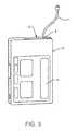
- FIG. 1is a perspective view of an infusion device embodiment having a user interface.
- FIG. 2is a perspective view of an infusion cartridge embodiment with an infusion set.
- FIG. 3depicts the infusion cartridge embodiment of FIG. 2 releasably secured to an infusion device housing of the infusion device embodiment of FIG. 1 .
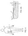
- FIG. 4depicts an infusion device attached to and in functional communication with a patient.
- FIG. 4Ais a view of the tubing of the infusion set of FIG. 4 subcutaneously positioned under the tissue of the patient.
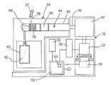
- FIG. 5is a schematic view of the infusion device of FIG. 3 .
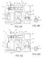
- FIG. 5Ais a perspective view of embodiments of a spool, a spool distal section, a variable volume cavity, and a driveshaft coupled to the spool main section.
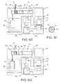
- FIG. 6Ais a schematic of the infusion device of FIG. 3 depicting the spool drawing a fluid from a reservoir into the variable volume.
- FIG. 6Bis a sectional view of a motor of the infusion device of FIG. 6A depicting an angular motion of a motorshaft.
- FIG. 6Cdepicts the infusion device of FIG. 6A with the spool moving into a position to deliver the fluid to an output port.
- FIG. 6Dis a sectional view of the motor of the infusion device of FIG. 6C depicting a motion of the motorshaft.
- FIG. 6Edepicts the infusion device of FIG. 6C with the spool performing a dispense cycle wherein a portion of the fluid contained within the variable volume cavity is delivered to the output port.
- FIG. 6Fis a sectional view of the motor of the infusion device of FIG. 6E depicting a motion of the motorshaft.
- FIG. 6Gshows the infusion device of FIG. 6E after a plurality of dispense cycles have been performed thereby transferring the full capacity contained within the variable volume cavity into the output port.
- FIG. 7is a graph that depicts the position of a spool over the time it takes to deliver a variable volume of fluid to the output port.
- FIG. 8Ais an enlarged view of the schematic of the infusion device shown in FIG. 5 depicting the spool main section of FIG. 5A at position x1 prior to a dispense cycle.
- FIG. 8Bdepicts the spool main section of FIG. 8A at position x2 at the termination of the dispense cycle.
- FIG. 8Cshows the spool of FIG. 8B after a residual displacement has moved the spool main section to position x3 after a rebound of the spool main section.
- FIG. 9Ais an enlarged view of the schematic of the infusion device shown in FIG. 5 depicting the spool main section at position x4 prior to a dispense cycle.
- FIG. 9Bdepicts the spool main section of FIG. 9A at position x5 at the termination of the dispense cycle.
- FIG. 9Cdepicts the spool of FIG. 9B after an overshoot residual displacement has moved the spool to position x6.
- FIG. 10is an enlarged view of the graph of FIG. 7 depicting a rebound residual displacement in the position of the spool after a dispense cycle.
- FIG. 11is an enlarged view of the graph of FIG. 7 depicting an overshoot residual displacement in the position of the spool after a dispense cycle.
- FIG. 12depicts a schematic view of the infusion device of FIG. 5 after an alarm has been triggered.
- FIG. 13is a flowchart of an embodiment of a method for detecting occlusions in an infusion device that is capable of delivering a single fluid.
- FIG. 14Adepicts a gearbox, driveshaft, a spool, and a linear encoder that measures the position of the spool at a first position.
- FIG. 14Bdepicts a gearbox, driveshaft, a spool, and a linear encoder that measures the position of the spool at a second position.
- Some embodiments of infusion devices and the method embodiments discussed hereinare directed to detection of a hindrance to the ability to deliver fluids to a patient.
- the hindrancemay be an occlusion between an output port of the infusion device and the patient who is connected to the infusion device by an infusion set.
- Some embodimentsmay include a mechanism by which the infusion device may alert a user of the infusion device to the presence of a full or partial occlusion in the infusion set.
- the occlusion detection device and method embodiments discussed hereinmay be used in conjunction with infusion device embodiments configured to deliver a single fluid to the patient, or with infusion device configurations configured to deliver multiple fluids to the patient.
- Embodiments of the infusion devicemay also be configured with a removable infusion cartridge which can contain the fluid or fluids in a single reservoir or in multiple reservoirs respectively.
- the infusion cartridgemay also have the capability of being refilled with the fluid or fluids by the user.
- an infusion devicethat is configured to detect a complete or partial occlusion may include a motor, a controller, a processor that is functionally linked to the controller, and a user interface which allows a user to operate the infusion device.
- the user interfacemay also provide the user with information regarding the delivery of the fluid or fluids.
- the infusion devicemay perform a dispense cycle wherein the therapeutic agent or agents are delivered to a patient through the infusion set.
- Each dispense cyclemay be performed by a spool which may be disposed within a bore inside the infusion cartridge.
- the dispense cyclemay begin when the processor instructs the controller to activate the motor that in turn advances the spool within the bore. As the spool is advanced in a first direction within the bore, it transfers fluid or fluids from the bore into the infusion set and subsequently to the patient.
- the spoolmay experience a residual displacement within the bore such that it moves in a second direction which is linearly opposed to the first direction. This is known as a “rebound” motion of the spool. It is also possible for the spool to have an “overshoot” residual displacement at the termination of a dispense cycle. In this case the spool continues to move in the first direction after the termination of power to the motor.
- data obtained by monitoring the magnitude of a residual displacement or the magnitudes of a plurality of residual displacementscan be used in order to determine if an occlusion may exist between the output port of the infusion device and the patient who is connected to the infusion device by the infusion set.
- a position measurement devicemay be used in order to determine the linear position of the spool within the bore.
- the processorcan then analyze that data to determine if the infusion set is occluded and alert the user via the user interface. The user can then clear the occlusion or replace the infusion set and then continue with the drug delivery therapy.
- FIGS. 1-4Adepict embodiments of an infusion device 10 with an infusion cartridge 12 having an infusion set 14 , as well as a diagram of the placement of the infusion device 10 on a patient 20 .
- An embodiment of an infusion device 10is shown in FIG. 1 .
- the infusion device 10may include a user interface 16 as is shown in FIG. 1 .
- FIG. 2depicts an infusion cartridge 12 in fluid communication with an infusion set 14 as well as an output port 18 .
- FIG. 3shows the infusion cartridge 12 inserted into the infusion device 10 .
- FIG. 4depicts an infusion device 10 secured to the body of a patient 20 .
- FIG. 4Ais a cross sectional view of FIG.
- FIG. 4showing the termination of the distal end 22 of the tubing 24 of the infusion set 14 in a subcutaneous position in the tissue 26 of the patient 20 .
- a fluidincluding a medicament such as insulin, 28 being delivered subcutaneously into the tissue 26 of the patient 20 through the infusion set 14 .
- the tubing 24may be held in place on the tissue 26 with an adhesive strip 30 .
- the infusion device 10may be configured as an ambulatory infusion pump.
- the infusion device 10alert a user to the presence of an occlusion between the output port 18 of the infusion device 10 and the patient 20 , who is typically the user, and who is connected to the infusion device 10 by the infusion set 14 .
- Thisis for the safety of the patient 20 and the therapeutic efficacy of the fluid 28 (typically a medicament such as insulin in the case of infusion devices used for diabetes) being delivered to the patient 20 .
- the various components of the infusion device 10may each play a role in the manner by which the infusion device assembly can detect and alert a user to an occlusion between the output port 18 of the infusion device 10 and the patient 20 who is connected to the infusion device 10 by the infusion set 14 .
- Some embodiments of the infusion device discussed hereinmay be configured to deliver a single fluid to the patient, while other embodiments of infusion devices may be configured to deliver multiple fluids, such as therapeutic fluids including insulin, an particularly, multiple insulin formulations of differing types, to the patient.
- multiple fluidssuch as therapeutic fluids including insulin, an particularly, multiple insulin formulations of differing types
- commonly owned U.S. Patent Publication No. 2013/0053816, Ser. No. 13/557,163, filed Jul. 24, 2012, by DiPerna et al. and titled Multi-Reservoir Infusion Pump Systems and Methodsis incorporated by reference herein in its entirety and discusses various embodiments of infusion devices or pumps that are configured to deliver multiple therapeutic fluids. When multiple fluids are delivered to the patient, the multiple fluids may be delivered either sequentially or simultaneously.
- the devices and methods of occlusion detection discussed hereinmay also be operatively applied to any suitable pump embodiment discussed in the incorporated patent publication 2013/0053816. Additional pump devices and methods that may be used in conjunction with the occlusion detection devices and methods discussed herein are also discussed in commonly owned U.S. Patent Publication No. 2011/0152770, Ser. No. 12/846,688, filed Jul. 29, 2010 by B. Bureson et al., titled Infusion Pump System with Disposable Cartridge Having Pressure Venting and Pressure Feedback, which is also incorporated by reference herein in its entirety. Further examples of such pumps include those disclosed in U.S. patent application Ser. No. 12/714,299, U.S. patent application Ser. No. 12/538,018, U.S.
- any of the infusion devices discussed or incorporated hereinmay be configured to be used as ambulatory pumps which may be conveniently carried on the person of the patient during use.
- Examples of such commercially available ambulatory infusion devicesinclude the T:slim® pump sold by Tandem Diabetes Care, Inc. of San Diego, Calif., the Paradigm® RevelTM pump sold by Medtronic Minimed, Inc. of Northridge, Calif. and the One Touch® Ping® pump sold by Animas Corporation of West Chester, Pa.
- any of the infusion devices discussed or incorporated hereinmay be used to deliver any useful fluid, such as a therapeutic fluid or fluids, to the patient.
- therapeutic fluids suitable for delivery by the infusion devices discussed or incorporated hereinmay include antibiotics, glucose, saline, glucagon, pramlintide or any other suitable liquid medicament.
- Non-medical applicationsare also contemplated.
- a regimented dosage of materialsin particular, the administration of insulin is typically required.
- the administration of insulin for a diabetic patientis one of a few medical indications wherein patient routinely administers the medicament to themselves by a subcutaneous modality.
- providing a patient with the means to safely, reliably and comfortably administer required doses of medicationmay be particularly important in order to facilitate patient compliance and accurate treatment of the condition.
- Blood glucoseis an important factor for metabolism and the provision of energy and proper organ functioning in mammals.
- the accurate regulation of blood glucoseis, therefore, an essential task necessary for the well-being of the mammal.
- the neurons of the brain of an organismdepend on glucose for fueling their functioning.
- blood glucose levelsare typically regulated by feedback loops between the brain and the pancreas.
- the pancreasfunctions in response to various hormones released by the brain by itself releasing hormones that regulate the uptake, e.g., storage, of blood sugar, or the release of stored blood sugar.
- two essential hormones in the regulation of blood sugar levelsare insulin and glucagon, both of which are synthesized by specialized cells in the pancreas.
- the ⁇ cells of the islets of Langerhansfunction to synthesize insulin
- the ⁇ cells of the islets of Langerhansfunction to synthesize glucagon.
- Maintaining appropriate blood glucose homeostasisis an important factor for promoting the length and quality of life.
- factors that affect the body's ability to maintain such homeostasisFor instance, factors such as the body's ability to produce or respond to insulin, one's physiological condition and/or health, the quantity and type of food one eats, one's metabolic rate, activity level, the types of activities and the exertion level in which one engages, as well as other such factors that make up a person's daily life and/or routine, all play important roles in effecting the body's ability to maintain homeostasis.
- Insulin injecting pumpshave been developed for the administration of insulin for those suffering from both type I and II diabetes.
- Insulin pumpsare medical devices used for the administration of insulin in the treatment of diabetes and offer an alternative to multiple daily injections of insulin by an insulin syringe or an insulin pen. They also allow for continuous insulin therapy.
- Patient compliancefor instance, is a major problem with respect to the use of insulin syringes. A high percent of subjects suffering from diabetes experience dread when it comes to insulin injections due to the anxiety and discomfort associated with regular use of a the needle therefore.
- a patient's insulin requirementsvary greatly, as mentioned above, and may be influenced by a variety of factors (e.g., caloric intake, physiological conditions). Therefore, in some cases, it may be desirable to provide patients with a user friendly portable infusion device having an interface that facilitates its use and having features that provide useful information about the device and its functions.
- FIG. 5An embodiment of an infusion device 32 with the ability to detect the presence of an occlusion and that may deliver a single fluid, such as a therapeutic fluid like insulin, is shown in FIG. 5 .
- the infusion device 32is similar to the one shown in FIG. 3 ; however the infusion device 32 is shown in a schematic view in FIG. 5 .
- the schematic viewis convenient in that it allows for the visual depiction of elements that may be contained within infusion device embodiments discussed herein.
- the schematic viewalso allows for the visual depiction of the movement of elements contained within the infusion device that are necessary to discuss the sequence of events that may be used to deliver fluid and to detect the presence of an occlusion.
- the infusion device 32 shown in FIG. 5incorporates an infusion cartridge 34 which may be detached from the infusion device 32 .
- the infusion cartridge 34is designed such that it contains elements that may be considered disposable, which is convenient as the removable infusion cartridge 34 may be detached from the infusion device 32 and discarded once the fluid contained within it has been delivered to a patient. A new removable infusion cartridge may then be attached to the infusion device 32 in order to facilitate the delivery of more fluid to the patient.
- the infusion cartridge 34may incorporate an output port 36 and a cylindrical bore 38 .
- the output port 36may be coupled to an infusion set 37 .
- the infusion cartridgemay also include a fluid reservoir 40 that contains a fluid 42 .
- a cylindrical spool 44may be slidably disposed within the bore 38 .
- the output port 36is in fluid communication with the bore 38 , which is in turn in fluid communication with the fluid reservoir 40 .
- the spool 42 disposed within the removable infusion cartridge 34is coupled to a driveshaft 46 which is in turn coupled to a gearbox 47 .
- a coupling element 48 of the driveshaft 46snaps into a socket section 50 of the spool 44 as is shown in FIG. 5A thereby securing the two together.
- the gearbox 47is in turn coupled to a motor 52 by a motorshaft 54 which can rotate in either a first angular direction or in a second angular direction.
- One purpose of the gearbox 47is to convert a rotational motion of the motorshaft 54 into a linear motion of the spool 44 within the bore 38 .
- the motor 52may also be in operative communication with a controller 56 , which may provide power to the motor 52 such that the motorshaft 54 rotates.
- FIG. 5also depicts a processor 58 that may include a system memory 60 .
- the system memory 60may be used in order to store processor instructions.
- the processor instructions stored in the system memory 60allow for the processor 58 to instruct other elements which are in operative communication with the processor 58 to perform specific tasks.
- the processor 58may be in operative communication with the controller 56 , and the processor instructions may instruct the processor 58 to activate the controller 56 such that it powers the motor 52 and turns the motorshaft 54 .
- the processor instructionsmay instruct the processor 58 to deactivate the controller 56 such that the power to the motor 52 is terminated.
- the processor 58may also be in operative communication with a filter 62 .
- the filter 62may incorporate a filter input and a filter output.
- the filter 62may be an Infinite Impulse Response (IIR) filter.
- IIR filtersare also known as exponential filters because the effects of an input change on the output decay exponentially.
- the IIR filter 62may be used in order to determine the “running average” of a series of input values.
- the IIR filter 62requires the storage of only one variable, the previous filter output.
- the equationaverages the current filter input r with the with the previous filter output f ⁇ -1 in order to determine the filter output f ⁇ .
- the outputmay be a weighted average of the two values as determined by the filter constant ⁇ . For example if the value of ⁇ is set at 0.8, the previous filter output value f ⁇ -1 is weighted at 80% and the filter input r is weighted at 20% during the averaging process.
- the filter constant ⁇may be determined by the following formula:
- Tis a time interval between specific events (for example the duration of a dispense cycle) and ⁇ is a time constant which may be programmed into the filter at startup.
- the filter constant ⁇may also be determined empirically and stored in the filter at startup.
- FIG. 5also depicts an encoder 64 that is disposed in proximity to the motor 52 and that may be in operative communication with the processor 58 .
- the purpose of the encoder 64is to relay information about the position and movement of the motorshaft 54 to the processor 58 .
- Information about the position and movement of the motorshaft 54may be used to indirectly measure the position spool 44 within the bore 38 . In such cases, a rotational motion of the motorshaft 54 is translated into a linear motion of the spool 44 by the gearbox, 47 therefore the rotational motion of the motorshaft 54 can be correlated to a linear motion of the spool 44 .
- FIG. 5Adepicts the spool coupled to the driveshaft 46 .
- a spool main section 66is coupled to a spool distal section 68 .
- the spool distal section 68 and the spool main section 66together form a variable volume cavity 70 .
- the spool distal section 68may move independently of the spool main section 66 as constrained by an enlarged portion 72 of the spool distal section 68 which is mechanically captured by a cavity 74 of the spool main section 66 .
- the spool distal section 68may be displaced relative to the spool main section 66 over limited distances.
- the volume of the variable volume cavity 70may be determined by the position of the spool main section 66 with respect to the spool distal section 68 in such embodiments.
- a dispense cycle of fluid 42may be performed by the spool 44 by decreasing the volume of the variable volume cavity 70 .
- the maximum volume of fluid 42 that may be contained within the variable volume cavity 70is a variable volume, defined at a point where the spool distal section 68 is displaced at a maximum separation distance from the spool main section 66 as determined by the captured enlarged portion 72 and cavity 74 .
- FIG. 5Adepicts a variable volume 76 of fluid 42 contained in the variable volume cavity 70 .
- a dispense cycledelivers a portion of the variable volume 76 to the patient.
- the portion of the variable volume 76 delivered to the patientwill be referred to as a sub-variable volume.
- the infusion device 32delivers the fluid 42 contained within the fluid reservoir 40 by delivering a series of variable volumes 76 of fluid 42 until the fluid reservoir 40 is nearly empty.
- each variable volume 76 of fluid 42is dispensed by a series of dispense cycles, with each dispense cycle dispensing a sub-variable volume of the variable volume 76 .
- FIG. 6Ashows the infusion device 32 performing a fill step wherein the spool 44 is moved into a location to perform a dispense cycle, and the variable volume cavity 70 is filled with fluid 42 from the fluid reservoir 40 .
- the processor 58instructs the controller 56 to activate the motor 52 such that the motorshaft 54 rotates in a first angular direction.
- the rotation of the motorshaft 54 in the first angular directionis indicated by the arrow 78 shown in FIG. 6B .
- the gearbox 47transforms the rotational motion of the motorshaft 54 in the first angular direction into a translational motion of the spool 44 in a first linear direction as indicated by the arrow 80 in FIG. 6A .
- the encoder 64may be used to indirectly monitor the position of the spool 44 by measuring the angular position of the motorshaft 54 .
- the motion of the spool 44specifically of the motion of the spool main section 66 , draws fluid 42 from the fluid reservoir 40 and into the variable volume cavity 70 .
- the fill stepterminates when the variable volume cavity 76 is filled with fluid 42 and the spool distal section 68 and spool main section 66 are at maximum separation.
- the variable volume cavity 70is positioned near the output port 36 .
- the processor 58may instruct the controller 56 to terminate power to the motor 52 as the spool 44 is in position to perform the dispense cycle.
- FIGS. 6E-6Gdepict the infusion device embodiment 32 as it performs a dispense cycle.
- the dispense cyclebegins with the processor 58 instructing the controller 56 to provide power to the motor 52 such that a motive force is generated.
- the motive forcerotates the motorshaft 54 in a second angular direction as indicated by the arrow 82 in FIG. 6F .
- the motorshaft 54 rotating in the second angular directionactivates the gearbox 47 which in turn causes the driveshaft 46 and therefore the spool 44 to translate in a second linear direction as indicated by the arrow 84 in FIG. 6E .
- the processor 58uses processor instructions to record position data from the encoder 64 in order to determine the position of the spool 44 during the dispense cycle, and the distance the spool 44 travels as measured by the encoder 64 and recorded by the processor 58 determines the duration of the dispense cycle.
- the processor 58instructs the controller 56 to terminate power to the motor 52 thereby ceasing the powered rotation of the motorshaft 54 .
- the spool 44may move in either the first or second linear direction after the controller 56 terminates power to the motor 52 . This movement is referred to as residual displacement of the spool 44 .
- the residual displacement of the spool 44is translated through the driveshaft 46 , gearbox 47 , and motor 52 to the motorshaft 54 where the magnitude of the residual displacement may be measured by the encoder 64 and reported to the processor 58 as a residual displacement datum.
- the processor 58may then store the residual displacement datum in the system memory 60 .
- the dispense cyclehas ended in that a sub-variable volume has been delivered to the output port 36 and the processor 58 has recorded a residual displacement datum as measured by the encoder 64 . It may be noted that the motion of the spool 44 depicted in FIGS. 6C and 6E carrying out a single dispense cycle is greatly exaggerated for the purpose of visualizing the dispense cycle.
- the motion of the spool 44may be much less than is depicted in the two figures. That is to say, in some instances it takes multiple dispense cycles to dispense the fluid 42 contained within the variable volume cavity 70 . In some cases the variable volume 76 of fluid may be dispensed in about 1 to about 100 delivery cycles.
- FIG. 6Gshows the spool 44 after a variable volume 76 of fluid has been dispensed from the variable volume cavity 70 by multiple dispense cycles.
- the infusion device elements that are used to carry out a dispense cyclemay also be used in order to alert a user of the infusion device to the presence of an occlusion.
- the magnitude of the residual displacement datamay vary over the course of multiple delivery steps. That is if there is an occlusion between the output port 36 and the patient, pressure may build up in the infusion set 37 . This pressure, sometimes referred to as “back pressure”, can lead to an increase in the magnitude of the residual displacement of the spool 44 after a dispense cycle. Accordingly the magnitude of the residual displacement datum as recorded by the encoder 64 may be used an indication of the presence of an occlusion.
- a single residual displacement datummay be analyzed in order to alert the user of the infusion device 32 to the presence of an occlusion between the output port 36 and the patient.
- the encoder 64may send the residual displacement datum to the processor 58 .
- the processor 58may then compare the residual displacement datum to a stored value to determine if an occlusion criterion is met. For example the processor 58 may compare the residual displacement datum to the filter output of the filter 62 , and if the residual displacement datum is significantly higher than the filter output or is higher by a threshold value, the processor 58 could then trigger an alarm 86 (as shown in FIG.
- the processor 58may compare the residual displacement datum to a stored value in the system memory 60 , and if the residual displacement datum is significantly higher than the stored value or is higher than a threshold value, the processor 58 could then trigger the alarm 86 in order to alert a user of the infusion device 32 to the presence of an occlusion.
- the residual displacement datummay be measured either in the first linear direction (as a rebound of the spool 44 ) or in the second linear direction (as an overshoot of the spool 44 ).
- the ability to detect an occlusion from a single residual displacement datummay be limited by the fact that the residual displacement datum may be an overshoot value and thus may not be indicative of excess pressure in the infusion set 37 .
- FIG. 7is a graph depicting the position of the spool 44 over the course of multiple delivery steps which may deliver a variable volume 76 of fluid.
- the vertical axis of the chartrepresents the position of the spool 44 over time, which is represented as the horizontal axis of the chart.
- Each “step” in the chartrepresents one delivery cycle. The initial shape of each step determines if the residual displacement of the spool 44 is a rebound or an overshoot motion of the spool 44 .
- FIGS. 8A-8Cshow an enlarged view of the infusion device FIG. 5 , showing the spool 44 , the spool main section 66 , the spool distal section 68 , the bore 38 , the fluid 42 , and the output port 36 .
- the figuresdepict a single dispense cycle and subsequent residual displacement in the form of a rebound of the spool 44 .
- the spool main section 66is shown at position X1 (the beginning of a dispense cycle) in FIG. 8A , which also depicts a variable volume 76 of fluid 42 contained within the variable volume cavity 70 . Note that in each figure the position marked as X0 indicates a relative zero position for each of the other positions.
- X1the beginning of a dispense cycle
- FIG. 8Athe dispense cycle has been initiated in that the spool main section 66 has begun to move in the second linear direction as indicated by the arrow 90 and the fluid 42 is being transferred from the variable volume cavity 70 to the output port 36 .
- FIG. 8Bdepicts the spool main section 66 after power to the motor 52 has been terminated. The spool main section 66 is now at position X2, and note that the spool distal section 68 has not moved from its position in FIG. 8A .
- FIG. 8Cdepicts the spool main section 66 after it has moved in the first linear direction as indicated by the arrow 92 (with the power to the motor 52 off) to position X3.
- the spool main section 66has thus undergone a residual displacement in the form of a rebound. It should be noted that throughout this document and without limiting the scope of the invention, stating that a residual displacement motion of the spool 44 has occurred is equivalent to stating that a residual displacement motion of the spool main section 66 has occurred. This applies to both rebound and overshoot motion of the spool 44 .
- the magnitude of the rebound residual displacementmay vary according to several factors.
- the first factoris friction between the spool main section 66 and the bore 38 .
- the spool 44 and sections thereofmay be separated from the bore 38 by a plurality of flexible gaskets or seals 88 as shown in FIGS. 8A-8C .
- the seals 88may become deformed as the motor 52 advances the spool main section 66 in the second linear direction.
- the motor 52is turned off and the seals 88 can recover to their original shape thereby causing the spool main section 66 to perform a residual displacement in the form of a rebound which occurs in the first linear direction.
- Another factor that may contribute to a rebound of the spool 44may be fluid pressure in the infusion set 37 . If a fluid lumen within the infusion set 37 is partially or completely occluded, as more fluid 42 is delivered into the fluid lumen during a delivery step, the pressure in the fluid lumen will increase. The fluid delivery step will deliver more fluid 42 into the fluid lumen and therefore the pressure in the fluid lumen will increase. This increase in pressure or backpressure from the occlusion may result in a rebound of the spool 44 within the bore 38 .
- FIGS. 9A-9Care enlarged views the infusion device 32 of FIG. 5 showing the spool 44 , the spool main section 66 , the spool distal section 68 , the bore 38 , the fluid 42 , and the output port 36 .
- FIG. 9Adepicts a variable volume 76 of fluid 42 contained within the variable volume cavity 70 .
- the figuresdepict a single dispense cycle and subsequent residual displacement in the form of an overshoot of the spool 44 (specifically of the spool main section 66 ).
- the spool main section 66is shown at position X4 (the beginning of a dispense cycle) in FIG. 9A .
- FIGS. 9A-9Care enlarged views the infusion device 32 of FIG. 5 showing the spool 44 , the spool main section 66 , the spool distal section 68 , the bore 38 , the fluid 42 , and the output port 36 .
- FIG. 9Adepicts a variable volume 76
- FIG. 9A-9Cthe position marked as X0 indicates a relative zero position for each of the other positions.
- the dispense cyclehas been initiated in that the spool main section 66 has begun to move in the second linear direction as indicated by the arrow 94 and the fluid 42 is being transferred from the variable volume cavity 70 to the output port 36 .
- FIG. 9Bdepicts the spool main section 66 after power to the motor 52 has been terminated and the spool main section 66 is now at position X5. Note that the spool distal section 68 has not moved from the position it occupied in FIG. 9A .
- FIG. 9Bdepicts the spool main section 66 after power to the motor 52 has been terminated and the spool main section 66 is now at position X5. Note that the spool distal section 68 has not moved from the position it occupied in FIG. 9A .
- FIG. 9Cdepicts the spool main section 66 after it has moved in the second linear direction as indicated by the arrow 96 (with the power to the motor 52 off) to position X6.
- the spool main section 66has thus undergone a residual displacement in the form of an overshoot.
- a residual displacement in the form of an overshootmay be caused by a backlash in the system that has not yet been taken out by the motion of the spool during the dispense cycle.
- the backlashmay be caused by friction between spool and the bore, specifically between the gaskets attached to the variable volume spool and the interior surface of the bore. The backlash may occur as the seals are deformed during the dispense cycle and then recover at the termination of the dispense cycle thereby causing an overshoot of the spool.
- the backlashmay also be caused by spacing between the teeth of the gears disposed within in the gearbox 47 . Additionally, any significant reduction in the force to move the spool 44 may result an overshoot motion of the spool 44 .
- FIG. 10is an enlarged view of the chart contained in FIG. 7 .
- FIG. 10graphically represents the different positions of the spool main section 66 over the course of dispense cycle and a subsequent residual displacement in the form of a rebound as depicted in FIGS. 8A-8C and discussed above.
- Position X1is the position of the spool main section at the beginning of the delivery cycle.
- Position X2is the position of the spool main section 66 when the power to the motor 52 is terminated.
- Position X3is the position of the spool main section 66 after it has undergone a residual displacement in the form of a rebound. As is indicated on the graph in FIG.
- the residual displacement datumrepresents the magnitude of the difference in the position of the spool main section 66 when it is at position X2 and when it at position X3, that is the difference in the position of the spool main section 66 between the termination of power to the motor 52 and the cessation of motion of the spool main section 66 .
- FIG. 11is an enlarged view of a portion of the graph of FIG. 7 .
- FIG. 10graphically represents the different positions of the spool main section 66 over the course of the dispense cycle and subsequent residual displacement in the form of an overshoot as depicted in FIGS. 9A-9C and discussed above.
- Position X4is the position of the spool main section 66 at the beginning of the delivery cycle.
- Position X5is the position of the spool main section 66 when the power to the motor 52 is terminated.
- Position X6is the position of the spool main section 66 after it has undergone a residual displacement in the form of an overshoot. As is indicated on the graph in FIG.
- the residual displacement datumrepresents the magnitude of the difference in the position of the spool main section 66 when it is at position X5 and compared to when it at position X6. Put another way, the residual displacement datum represents the difference in the position of the spool main section 66 between the time of termination of power to the motor 52 and the time of cessation of motion of the spool main section 66 .
- the delivery of a variable volume of fluidmay be broken down into a plurality of dispense cycles each of which delivers a sub-variable volume from the variable volume cavity 70 to the output port 37 .
- Each dispense cyclemay begin with the processor 58 instructing the controller 56 to provide power to the motor 52 in order to generate a motive force.
- the motive forcecauses the motorshaft 54 to rotate in the second angular direction as shown in FIG. 6F .
- the gearbox 47translates the rotation of the motorshaft 54 in the second angular direction into a motion of the driveshaft 46 and spool 44 in the second linear direction indicated by the arrow in FIG. 6E .
- the motion of the spool 44 in the second linear directiondecreases the volume of the variable volume cavity 70 formed by the spool main section 66 and the spool distal section 68 which remains motionless within the bore 38 .
- the fluid 40is transferred from the variable volume cavity 70 to the output port 36 .
- the fluid 40is then delivered to the patient through the infusion set 37 .
- the processor 58may then instruct the controller 56 to terminate power to the motor 52 .
- the spool 44may experience a residual displacement.
- the residual displacementwill be translated from the spool 44 to the motorshaft 54 through gearbox 47 which transforms the linear motion of the driveshaft 46 and spool 44 into a rotational motion of the motorshaft 54 .
- the magnitude of the residual displacementmay be measured by the encoder 64 , which measures the angular position of the motorshaft 54 .
- the processor 58which is on operative communication with the encoder 64 records a residual displacement datum and stores it in the system memory 60 .
- the dispense cycleconcludes at the cessation of motion of the spool main section 66 .
- dispense cycleseach of which dispenses a sub-variable volume, may be required to dispense a variable volume 76 of fluid to a patient. It is possible for the processor 58 to store in the system memory 60 each residual displacement datum measured by the encoder 64 alter each dispense cycle. After the delivery of the variable volume 76 of fluid 42 , the processor 58 may sum the residual displacement data stored in the system memory 60 . The processor 58 may sum the residual displacement data using an algorithm or using a summing circuit. By summing the residual displacement data from each dispense cycle the processor 58 generates a residual sum value from the residual displacement data.
- the processor 58may then compare the residual sum value to a stored value to determine if an occlusion criterion is met. For example the processor 58 may compare the residual sum value to a filter output of the filter 62 , and if the residual sum value is higher than the filter output by a threshold value, the processor 58 could then trigger an occlusion alarm 86 (as shown in FIG. 12 ) in order to alert a user of the infusion device 32 to the presence of an occlusion.
- the processor 58may compare the residual sum value to a stored value which is stored in the system memory 60 , and if the residual sum is significantly higher than the stored value or higher by at least a threshold value, the processor 58 could then trigger the occlusion alarm 86 (as shown in FIG. 12 ) in order to alert a user of the infusion device 32 to the presence of an occlusion.
- the methods and embodiments described thus far to detect an occlusion in an infusion devicecould be further enhanced by analyzing a plurality of residual sum values from a plurality of respective variable volumes dispensed. That is to say, if multiple respective variable volumes 76 of fluid 42 are each dispensed with multiple dispense cycles, multiple residual sum values may be generated. Each variable volume 76 will be dispensed with multiple dispense cycles, thereby resulting in a plurality of residual displacement datum for each variable volume 76 dispensed. The residual displacement data for each variable volume 76 dispensed may be summed in order to generate a respective residual sum value.
- the generation and analysis of multiple residual sum valuesallows for greater statistical accuracy with regards to detecting an occlusion than does the generation and analysis of a single residual displacement datum, or the generation and analysis of a single residual sum datum.
- each dispense cyclemay begin with the processor 58 instructing the controller 56 to provide power to the motor 52 in order to generate a motive force.
- the motive forcecauses the motorshaft 54 to rotate in the second angular direction as shown in FIG. 6E .
- the gearbox 47translates the rotation of the motorshaft 54 in the second angular direction into a motion of the driveshaft 46 and spool 44 in the second linear direction indicated in FIG. 6E .
- the motion of the spool 44 in the second linear directiondecreases the volume of the variable volume cavity 70 formed between the spool main section 66 and the spool distal section 68 which remains substantially motionless within the bore 38 during a dispense cycle.
- variable volume cavity 70As the volume of the variable volume cavity 70 is decreased by the motion of the spool main section 66 , fluid 42 is transferred from the variable volume cavity 70 into the output port 36 . The fluid 42 is then delivered to the patient through the infusion set 37 . The processor 58 may then instruct the controller 56 to terminate power to the motor 52 . Although power to the motor 52 has been terminated, the spool 44 may experience a residual displacement. The residual displacement will be translated from the spool 44 to the motorshaft 54 through gearbox 47 which transforms the linear motion of the driveshaft 46 and spool 44 into a rotational motion of the motorshaft 54 . The magnitude of the residual displacement may be measured by the encoder 64 , which may measure the angular position of the motorshaft 54 .
- the processor 58which is on operative communication with the encoder 64 , records the residual displacement datum and stores it in the system memory 60 .
- the dispense cycleconcludes at the cessation of motion of the main spool section 66 within the bore 38 .
- each dispense cycle dispensing a sub-variable volumeis required to dispense each variable volume 76 of fluid 42 to a patient. It is possible for the processor 58 to store in the system memory 60 each residual displacement datum measured by the encoder 64 after each dispense cycle. After the delivery of each variable volume 76 of fluid 42 , the processor 58 may sum the residual displacement data stored in the system memory 60 for that specific variable volume 76 . The processor 58 may sum the residual displacement data for the specific variable volume 76 of fluid using an algorithm or using a summing circuit. By summing the residual displacement data for the specific variable volume 76 of fluid 42 from each dispense cycle the processor 58 may generate a residual sum value from the residual displacement data for each of the variable volumes 76 dispensed.
- a variety of analytical methodsmay be applied to the residual sum data in order to determine if an occlusion may exist between the output port 36 of the infusion device 32 and a patent who is connected to the infusion device 32 an infusion set 37 .
- the average residual sum valuesmay then be used as a standard to which all residual sum values subsequently generated may be compared.
- the filter 62has a filter output f ⁇ which is the weighted average (see equation 1) of the filter input r and the previous filter output f ⁇ -1 .
- the weighting between the two valuesmay be entirely determined by the filter constant ⁇ .
- the filtercan thus be used to create a running average of a sequential series of values; in this case, a sequential series of residual sum values.
- each residual sum valuemay be loaded into the filter as the filter input r (again see equation 1).
- the filter output f ⁇will then be the weighted average of the residual sum value r just loaded into the filter, and the previous averaged residual sum value f ⁇ -1 . If the filter input r is the first residual sum value loaded into the filter 62 , then the filter output f ⁇ can be that same residual sum value. The averaging will begin when the next value is loaded into the filter 62 .
- a plurality of residual sum valuesmay be loaded into the filter 62 in order to generate a nominal filter output value.
- the nominal filter output valuemay be generated by loading about 2 to about 10 successive residual sum values into the filter 62 .
- the nominal filter output valuemay be used as a standard by which to compare residual sum values subsequently generated in order to determine if an occlusion criterion is satisfied. For example, a succession of residual sum values generated after the nominal filter output value may be compared to the nominal filter output value to determine if each residual sum value exceeds the nominal filter output value by a threshold difference value.
- the threshold difference valuemay be defined as a residual sum value being at least about 20% higher in value than the nominal filter output value.
- An occlusion criterionmay be further defined as having at least about 2 to about 10 residual sum values exceed the nominal filter output value by the threshold difference value.
- FIG. 13is a flow chart detailing the generation and analysis of multiple residual sum values in order to determine if an occlusion may exist between the output port 36 of the infusion device 32 and a patient who is attached to the infusion device 32 by the infusion set 37 .
- the flowchartsummarizes the procedure that has been discussed above for analyzing multiple residual sum values from multiple respective variable volumes 76 of fluid 42 dispensed.
- the flowchart in FIG. 13begins with box 98 which depicts the variable volume cavity 70 of the spool 44 being filled with a variable volume 76 of fluid 42 .
- Box 100depicts the performing of a dispense cycle as described above.
- Box 102depicts the measurement of a residual displacement datum by the encoder 64 after each dispense cycle.
- Box 104depicts the storing of the residual displacement datum in the system memory 60 by the processor 58 .
- Box 106depicts multiple dispense cycles being performed until the variable volume 76 of fluid 42 is dispensed i.e. the spool main section 66 and spool distal section 68 are at maximum separation. Note that some fluid 42 will remain in the variable volume cavity 70 in this state.
- Box 108depicts a residual sum value being generated by summing all of the residual displacement data which has been generated in box 102 and stored in the system memory 60 in box 104 .
- Box 110depicts the residual sum value generated in box 108 being loaded into the filter 62 .
- Box 112depicts multiple residual sum values having been loaded into the filter 62 . After about 2 to about 10 residual sum values are loaded into the filter 62 , the filter output is declared the nominal filter output value as depicted in box 114 .
- variable volume cavity 70is then completely filled again with a variable volume 76 of fluid 42 as depicted in box 116 . Then a dispense cycle is performed as depicted in box 118 .
- Box 120depicts the measurement of a residual displacement datum by the encoder 64 ater each dispense cycle.
- Box 122depicts the storing of the residual displacement datum in the system memory 60 by the processor 58 .
- Box 124depicts multiple dispense cycles being performed until the variable volume 76 of fluid 42 is dispensed i.e. the spool main section 66 and spool distal section 68 are at maximum separation. Note that some fluid 42 will remain in the variable volume cavity 70 in this state.
- Box 126depicts a residual sum value being generated by summing all of the residual displacement data which has been generated in box 120 and stored in the system memory 60 in box 122 .
- the residual sum valueis then compared to the nominal filter output value generated in box 114 .
- the variable volume cavity 70is then filled again and another residual sum value is generated after it is dispensed via a series of dispense cycles as depicted in boxes 116 - 124 .
- the residual sum valueis then compared to the nominal filter output value generated in box 114 .
- variable volumes 76 of fluid 42will continue to be dispensed unless about 2 to about 10 residual sum values exceed the nominal filter output value generated in box 114 by a significant value or by a threshold difference value. When that occurs, the dispensing is stopped and an alarm is triggered as depicted in box 130 .
- FIGS. 14A and 14Bdepict a spool 132 having an optical pattern 134 .
- FIG. 14Aalso depicts an optical encoder 136 , a gearbox 138 , and a driveshaft 140 .
- the encoder 136sends an optical signal 142 to the optical pattern 134 thereby establishing the position of the spool 132 .
- FIG. 14Bdepicts the spool 132 in a different position, with the optical encoder 136 sending an optical signal 142 to the optical pattern 134 in order to measure the new position of the spool 132 .
- the encoder embodiment 132 depicted in FIGS. 14A and 14Btherefore measures the linear position of the spool 132 directly as opposed to measuring the angular position of the motorshaft 54 as has been previously described.
Landscapes
- Health & Medical Sciences (AREA)
- Vascular Medicine (AREA)
- Engineering & Computer Science (AREA)
- Anesthesiology (AREA)
- Biomedical Technology (AREA)
- Heart & Thoracic Surgery (AREA)
- Hematology (AREA)
- Life Sciences & Earth Sciences (AREA)
- Animal Behavior & Ethology (AREA)
- General Health & Medical Sciences (AREA)
- Public Health (AREA)
- Veterinary Medicine (AREA)
- Infusion, Injection, And Reservoir Apparatuses (AREA)
Abstract
Description
fμ=(1−α)·r+α·fμ-1 (1)
Claims (15)
Priority Applications (1)
| Application Number | Priority Date | Filing Date | Title |
|---|---|---|---|
| US13/832,531US9421329B2 (en) | 2013-03-15 | 2013-03-15 | Infusion device occlusion detection system |
Applications Claiming Priority (1)
| Application Number | Priority Date | Filing Date | Title |
|---|---|---|---|
| US13/832,531US9421329B2 (en) | 2013-03-15 | 2013-03-15 | Infusion device occlusion detection system |
Publications (2)
| Publication Number | Publication Date |
|---|---|
| US20140276537A1 US20140276537A1 (en) | 2014-09-18 |
| US9421329B2true US9421329B2 (en) | 2016-08-23 |
Family
ID=51530767
Family Applications (1)
| Application Number | Title | Priority Date | Filing Date |
|---|---|---|---|
| US13/832,531Active2035-01-03US9421329B2 (en) | 2013-03-15 | 2013-03-15 | Infusion device occlusion detection system |
Country Status (1)
| Country | Link |
|---|---|
| US (1) | US9421329B2 (en) |
Cited By (14)
| Publication number | Priority date | Publication date | Assignee | Title |
|---|---|---|---|---|
| US9962486B2 (en) | 2013-03-14 | 2018-05-08 | Tandem Diabetes Care, Inc. | System and method for detecting occlusions in an infusion pump |
| US10010674B2 (en) | 2009-02-27 | 2018-07-03 | Tandem Diabetes Care, Inc. | Methods and devices for determination of flow reservoir volume |
| US10258736B2 (en) | 2012-05-17 | 2019-04-16 | Tandem Diabetes Care, Inc. | Systems including vial adapter for fluid transfer |
| US10279107B2 (en) | 2015-08-20 | 2019-05-07 | Tandem Diabetes Care, Inc. | Drive mechanism for infusion pump |
| EP3742449A1 (en) | 2019-05-21 | 2020-11-25 | Tandem Diabetes Care, Inc. | System and method for incorporating exercise into closed-loop diabetes therapy |
| US11135363B2 (en) | 2019-07-16 | 2021-10-05 | Beta Bionics, Inc. | Ambulatory medicament device alarm system |
| US11458246B2 (en) | 2018-02-05 | 2022-10-04 | Tandem Diabetes Care, Inc. | Methods and systems for detecting infusion pump conditions |
| US11497849B2 (en) | 2020-12-07 | 2022-11-15 | Beta Bionics, Inc. | Ambulatory medicament device with power saving mode |
| US11497852B2 (en) | 2020-12-21 | 2022-11-15 | Beta Bionics, Inc. | Ambulatory medicament device with power saving mode |
| USD980859S1 (en) | 2020-03-10 | 2023-03-14 | Beta Bionics, Inc. | Display screen with transitional graphical user interface |
| US11957876B2 (en) | 2019-07-16 | 2024-04-16 | Beta Bionics, Inc. | Glucose control system with automated backup therapy protocol generation |
| USD1032623S1 (en) | 2020-03-10 | 2024-06-25 | Beta Bionics, Inc. | Display screen with animated graphical user interface |
| USD1032624S1 (en) | 2020-03-10 | 2024-06-25 | Beta Bionics, Inc. | Display screen with animated graphical user interface |
| EP4531051A1 (en) | 2023-09-29 | 2025-04-02 | Tandem Diabetes Care, Inc. | Infusion pump with multi-cgm compatibility |
Families Citing this family (15)
| Publication number | Priority date | Publication date | Assignee | Title |
|---|---|---|---|---|
| US10279106B1 (en) | 2014-05-08 | 2019-05-07 | Tandem Diabetes Care, Inc. | Insulin patch pump |
| EP3050585B1 (en)* | 2015-01-27 | 2019-04-10 | Idorsia Pharmaceuticals Ltd | Dosing device for dispensing a fluid under aseptic conditions |
| WO2016205584A1 (en) | 2015-06-17 | 2016-12-22 | Smiths Medical Asd, Inc. | Force sensing devices, systems and method for syringe pumps |
| US10716915B2 (en) | 2015-11-23 | 2020-07-21 | Mivi Neuroscience, Inc. | Catheter systems for applying effective suction in remote vessels and thrombectomy procedures facilitated by catheter systems |
| US9889244B2 (en) | 2015-12-17 | 2018-02-13 | Fresenius Medical Care Holdings, Inc. | System and method for controlling venous air recovery in a portable dialysis system |
| US10987460B2 (en) | 2016-03-08 | 2021-04-27 | Fresenius Medical Care Holdings, Inc. | Methods and systems of generating rapidly varying pressure amplitudes in fluidic circuits in a dialysis treatment system |
| CN108778361B (en) | 2016-03-08 | 2021-09-28 | 费森尤斯医疗保健控股公司 | Method and system for detecting an occlusion in a blood circuit of a dialysis system |
| WO2018022204A1 (en)* | 2016-07-25 | 2018-02-01 | Smiths Medical Asd, Inc. | Group coordination of operational features of a plurality of medical devices |
| US10561778B2 (en) | 2017-03-02 | 2020-02-18 | Fresenius Medical Care Holdings, Inc. | Split reservoir bags and method of using split reservoir bags to improve the heating and generation of dialysate |
| US11110214B2 (en) | 2017-04-07 | 2021-09-07 | Fresenius Medical Care Holdings, Inc. | Methods and systems for measuring and heating dialysate |
| US10478535B2 (en) | 2017-05-24 | 2019-11-19 | Mivi Neuroscience, Inc. | Suction catheter systems for applying effective aspiration in remote vessels, especially cerebral arteries |
| US11234723B2 (en) | 2017-12-20 | 2022-02-01 | Mivi Neuroscience, Inc. | Suction catheter systems for applying effective aspiration in remote vessels, especially cerebral arteries |
| JP7616642B2 (en) | 2018-05-17 | 2025-01-17 | ルート92メディカル・インコーポレイテッド | Suction catheter system and method of use |
| US11617865B2 (en) | 2020-01-24 | 2023-04-04 | Mivi Neuroscience, Inc. | Suction catheter systems with designs allowing rapid clearing of clots |
| JP7584521B2 (en)* | 2020-01-31 | 2024-11-15 | ベクトン・ディキンソン・アンド・カンパニー | A pump that creates a pump chamber by expanding and contracting through friction |
Citations (137)
| Publication number | Priority date | Publication date | Assignee | Title |
|---|---|---|---|---|
| US3985133A (en) | 1974-05-28 | 1976-10-12 | Imed Corporation | IV pump |
| US4178938A (en) | 1977-06-24 | 1979-12-18 | Au Anthony S | Pressure control systems |
| US4650471A (en) | 1984-01-20 | 1987-03-17 | Yehuda Tamari | Flow regulating device for peristalitic pumps |
| US4919596A (en) | 1987-12-04 | 1990-04-24 | Pacesetter Infusion, Ltd. | Fluid delivery control and monitoring apparatus for a medication infusion system |
| US5000739A (en) | 1988-07-12 | 1991-03-19 | Pinewood Medical, Inc. | Programmable infusion pump |
| US5085644A (en) | 1990-04-02 | 1992-02-04 | Pudenz-Schulte Medical Research Corporation | Sterilizable medication infusion device with dose recharge restriction |
| US5087245A (en) | 1989-03-13 | 1992-02-11 | Ivac Corporation | System and method for detecting abnormalities in intravascular infusion |
| US5103211A (en) | 1989-11-02 | 1992-04-07 | Ivac Corporation | Apparatus for detecting fluid line occlusion |
| US5131816A (en) | 1988-07-08 | 1992-07-21 | I-Flow Corporation | Cartridge fed programmable ambulatory infusion pumps powered by DC electric motors |
| US5178603A (en) | 1990-07-24 | 1993-01-12 | Baxter International, Inc. | Blood extraction and reinfusion flow control system and method |
| US5215450A (en) | 1991-03-14 | 1993-06-01 | Yehuda Tamari | Innovative pumping system for peristaltic pumps |
| US5242408A (en) | 1992-09-23 | 1993-09-07 | Becton, Dickinson And Company | Method and apparatus for determining pressure and detecting occlusions in a syringe pump |
| US5247434A (en) | 1991-04-19 | 1993-09-21 | Althin Medical, Inc. | Method and apparatus for kidney dialysis |
| US5273406A (en) | 1991-09-12 | 1993-12-28 | American Dengi Co., Inc. | Pressure actuated peristaltic pump |
| US5304126A (en) | 1984-02-08 | 1994-04-19 | Abbott Laboratories | Infusion system having plural fluid flow lines |
| US5342180A (en) | 1992-11-17 | 1994-08-30 | Ivac Corporation | Pump mechanism having a drive motor with an external rotor |
| US5423743A (en) | 1993-09-17 | 1995-06-13 | Ivac Corporation | Cannula position detection |
| US5429483A (en) | 1989-09-22 | 1995-07-04 | Tamari; Yehuda | Pressure sensitive valves for extracorporeal pumping |
| US5438510A (en) | 1993-03-03 | 1995-08-01 | Deka Products Limited Partnership | User interface and monitoring functions for automated peritoneal dialysis systems |
| WO1995032013A1 (en) | 1994-05-23 | 1995-11-30 | Elan Medical Technologies Limited | Liquid delivery device |
| US5482446A (en) | 1994-03-09 | 1996-01-09 | Baxter International Inc. | Ambulatory infusion pump |
| US5498421A (en) | 1993-02-22 | 1996-03-12 | Vivorx Pharmaceuticals, Inc. | Composition useful for in vivo delivery of biologics and methods employing same |
| US5584667A (en) | 1988-05-17 | 1996-12-17 | Davis; David L. | Method of providing uniform flow from an infusion device |
| US5634896A (en) | 1993-03-03 | 1997-06-03 | Deka Products Limited Partnership | Liquid pumping mechanisms for peritoneal dialysis systems employing fluid pressure |
| US5658252A (en) | 1993-11-22 | 1997-08-19 | Sims Deltec, Inc. | Drug pump including pressure plate and tube |
| US5695473A (en) | 1994-07-27 | 1997-12-09 | Sims Deltec, Inc. | Occlusion detection system for an infusion pump |
| US5800387A (en) | 1996-10-04 | 1998-09-01 | Alaris Medical Systems, Inc. | Safety monitoring apparatus for a patient care system |
| US5803917A (en) | 1994-09-13 | 1998-09-08 | Alaris Medical Systems, Inc. | Fluid flow resistance monitoring system |
| US5885614A (en) | 1996-02-23 | 1999-03-23 | Hirsch; Alan R. | Use of odorants to treat male impotence, and article of manufacture therefor |
| US5971722A (en) | 1997-09-05 | 1999-10-26 | Baxter International Inc | Electrochemical syringe pump having a sealed storage reservoir for a charge transfer medium |
| USRE36871E (en) | 1984-02-08 | 2000-09-12 | Abbott Laboratories | Remotely programmable infusion system |
| US6120460A (en) | 1996-09-04 | 2000-09-19 | Abreu; Marcio Marc | Method and apparatus for signal acquisition, processing and transmission for evaluation of bodily functions |
| US6158965A (en) | 1996-07-30 | 2000-12-12 | Alaris Medical Systems, Inc. | Fluid flow resistance monitoring system |
| US6210361B1 (en) | 1997-08-22 | 2001-04-03 | Deka Products Limited Partnership | System for delivering intravenous drugs |
| WO2001030422A1 (en) | 1999-10-27 | 2001-05-03 | Alaris Medical Systems, Inc. | Positive pressure infusion system having downstream resistance measurement capability |
| US6280408B1 (en) | 1992-11-09 | 2001-08-28 | Anatole J. Sipin | Controlled fluid transfer system |
| US6302653B1 (en) | 1999-07-20 | 2001-10-16 | Deka Products Limited Partnership | Methods and systems for detecting the presence of a gas in a pump and preventing a gas from being pumped from a pump |
| US6310270B1 (en) | 1996-03-15 | 2001-10-30 | The General Hospital Corporation | Endothelial NOS knockout mice and methods of use |
| US6358225B1 (en) | 1995-08-31 | 2002-03-19 | Alaris Medical Systems, Inc. | Upstream occlusion detection system |
| US20020040208A1 (en) | 2000-10-04 | 2002-04-04 | Flaherty J. Christopher | Data collection assembly for patient infusion system |
| US6371732B1 (en) | 1998-11-09 | 2002-04-16 | Ahmad Maher Moubayed | Curvilinear peristaltic pump |
| US6381493B1 (en) | 1999-03-29 | 2002-04-30 | Medtronic, Inc. | Ischemia detection during non-standard cardiac excitation patterns |
| US6382923B1 (en) | 1999-07-20 | 2002-05-07 | Deka Products Ltd. Partnership | Pump chamber having at least one spacer for inhibiting the pumping of a gas |
| US6398760B1 (en) | 1999-10-01 | 2002-06-04 | Baxter International, Inc. | Volumetric infusion pump with servo valve control |
| US20020072733A1 (en) | 2000-09-08 | 2002-06-13 | Flaherty J. Christopher | Devices, systems and methods for patient infusion |
| US6416293B1 (en) | 1999-07-20 | 2002-07-09 | Deka Products Limited Partnership | Pumping cartridge including a bypass valve and method for directing flow in a pumping cartridge |
| US6447522B2 (en) | 1998-09-30 | 2002-09-10 | C. R. Bard, Inc. | Implant delivery system |
| US6447443B1 (en) | 2001-01-13 | 2002-09-10 | Medtronic, Inc. | Method for organ positioning and stabilization |
| US6471689B1 (en) | 1999-08-16 | 2002-10-29 | Thomas Jefferson University | Implantable drug delivery catheter system with capillary interface |
| US6475180B2 (en) | 1992-09-09 | 2002-11-05 | Sims Deltec, Inc. | Drug pump systems and methods |
| US6485461B1 (en) | 2000-04-04 | 2002-11-26 | Insulet, Inc. | Disposable infusion device |
| US6485263B1 (en) | 1998-07-01 | 2002-11-26 | Deka Products Limited Partnership | Systems for determining the volume of a volumetric chamber and pumping a fluid with a pump chamber |
| US6537268B1 (en) | 1998-06-18 | 2003-03-25 | Medtronic Minimed, Inc. | Medical infusion device with a source of controlled compliance |
| US20030097082A1 (en) | 2001-07-13 | 2003-05-22 | Board Of Regents, The University Of Texas System | Methods and apparatuses for navigating the subarachnoid space |
| US6604908B1 (en) | 1999-07-20 | 2003-08-12 | Deka Products Limited Partnership | Methods and systems for pulsed delivery of fluids from a pump |
| US6669669B2 (en) | 2001-10-12 | 2003-12-30 | Insulet Corporation | Laminated patient infusion device |
| US6759386B2 (en) | 2000-04-06 | 2004-07-06 | Wayne P. Franco | Methods of use of fibroblast growth factor, vascular endothelial growth factor and related proteins in the treatment of acute and chronic heart disease |
| US20040133220A1 (en) | 2000-01-31 | 2004-07-08 | Randall Lashinski | Adjustable transluminal annuloplasty system |
| US6801420B2 (en) | 2001-04-19 | 2004-10-05 | Medtronic Minimed, Inc. | Selective potting for controlled failure and electronic devices employing the same |
| US6804002B2 (en) | 2000-06-11 | 2004-10-12 | Orsense Ltd. | Method and device for measuring concentration of glucose or other substances in blood |
| US20040260233A1 (en) | 2000-09-08 | 2004-12-23 | Garibotto John T. | Data collection assembly for patient infusion system |
| US20050054994A1 (en) | 2002-09-25 | 2005-03-10 | Iulian Cioanta | Catheters with suction capability and related methods and systems for obtaining biosamples in vivo |
| US20050060030A1 (en) | 2000-01-31 | 2005-03-17 | Lashinski Randall T. | Remotely activated mitral annuloplasty system and methods |
| US6877713B1 (en) | 1999-07-20 | 2005-04-12 | Deka Products Limited Partnership | Tube occluder and method for occluding collapsible tubes |
| US6905479B1 (en) | 1999-07-20 | 2005-06-14 | Deka Products Limited Partnership | Pumping cartridge having an integrated filter and method for filtering a fluid with the cartridge |
| US20050171569A1 (en) | 2000-04-25 | 2005-08-04 | Impres Medical, Inc. | Method and apparatus for creating intrauterine adhesions |
| WO2005082450A1 (en) | 2004-02-20 | 2005-09-09 | Fluidnet Llc | Automated fluid flow control system |
| US6948918B2 (en) | 2002-09-27 | 2005-09-27 | Novo Nordisk A/S | Membrane pump with stretchable pump membrane |
| US6997202B2 (en) | 2002-12-17 | 2006-02-14 | Advanced Technology Materials, Inc. | Gas storage and dispensing system for variable conductance dispensing of gas at constant flow rate |
| US7090648B2 (en) | 2000-09-28 | 2006-08-15 | Non-Invasive Monitoring Systems, Inc. | External addition of pulses to fluid channels of body to release or suppress endothelial mediators and to determine effectiveness of such intervention |
| US7107706B1 (en) | 1997-08-14 | 2006-09-19 | Promdx Technology, Inc. | Ergonomic systems and methods providing intelligent adaptive surfaces and temperature control |
| US20060264835A1 (en) | 2003-10-21 | 2006-11-23 | Novo Nordisk A/S | Medical skin mountable device |
| US7163520B2 (en) | 2002-06-26 | 2007-01-16 | Chf Solutions, Inc. | Method and device for removal of radiocontrast media from blood |
| US7166280B2 (en) | 2000-04-06 | 2007-01-23 | Franco Wayne P | Combination growth factor therapy and cell therapy for treatment of acute and chronic heart disease |
| US7193521B2 (en) | 1998-10-29 | 2007-03-20 | Medtronic Minimed, Inc. | Method and apparatus for detecting errors, fluid pressure, and occlusions in an ambulatory infusion pump |
| US20070100222A1 (en) | 2004-06-14 | 2007-05-03 | Metronic Minimed, Inc. | Analyte sensing apparatus for hospital use |
| US20070112301A1 (en) | 2004-03-30 | 2007-05-17 | Novo Nordisk A/S | Actuator system comprising detector means |
| WO2007065944A1 (en) | 2005-12-08 | 2007-06-14 | Novo Nordisk A/S | Medical system comprising a sensor device |
| US7264730B2 (en) | 1991-04-19 | 2007-09-04 | Baxter International Inc. | Methods for kidney dialysis |
| US7265091B2 (en) | 2000-07-21 | 2007-09-04 | The Regents Of The University Of California | Methods and compositions for treating male erectile dysfunction |
| US20070219496A1 (en) | 2006-02-09 | 2007-09-20 | Dean Kamen | Pumping fluid delivery systems and methods using force application assembly |
| US7338464B2 (en) | 2001-03-01 | 2008-03-04 | Advanced Neuromodulation Systems, Inc. | Non-constant pressure infusion pump |
| US20080058697A1 (en) | 2006-04-14 | 2008-03-06 | Deka Products Limited Partnership | Heat exchange systems, devices and methods |
| US20080082040A1 (en) | 2006-09-08 | 2008-04-03 | Christoph Kubler | Surgical system |
| US20080125700A1 (en) | 2006-11-29 | 2008-05-29 | Moberg Sheldon B | Methods and apparatuses for detecting medical device acceleration, temperature, and humidity conditions |
| US20080172027A1 (en) | 2006-10-17 | 2008-07-17 | Blomquist Michael L | Insulin pump having basal rate testing features |
| US20080221523A1 (en) | 1998-10-29 | 2008-09-11 | Medtronic Minimed, Inc. | Methods and apparatuses for detecting occlusions in an ambulatory infusion pump |
| US7429269B2 (en) | 2003-07-08 | 2008-09-30 | Ventor Technologies Ltd. | Aortic prosthetic devices |
| US7473239B2 (en) | 2003-08-25 | 2009-01-06 | The University Of Texas System | Single expandable double lumen cannula assembly for veno-venous ECMO |
| US7476209B2 (en) | 2004-12-21 | 2009-01-13 | Therakos, Inc. | Method and apparatus for collecting a blood component and performing a photopheresis treatment |
| US20090069785A1 (en) | 2007-09-07 | 2009-03-12 | M2 Medical Group Holdings, Inc. | User Profile Backup System For an Infusion Pump Device |
| US20090069749A1 (en) | 2007-09-07 | 2009-03-12 | M2 Medical | Power Management Techniques for an Infusion Pump System |
| US7503903B2 (en) | 2004-02-20 | 2009-03-17 | Fluidnet Corporation | Automated fluid flow control system |
| US7517440B2 (en) | 2002-07-17 | 2009-04-14 | Eksigent Technologies Llc | Electrokinetic delivery systems, devices and methods |
| US7534226B2 (en) | 2005-09-26 | 2009-05-19 | M2 Group Holdings, Inc. | Dispensing fluid from an infusion pump system |
| US7604592B2 (en) | 2003-06-13 | 2009-10-20 | Pelikan Technologies, Inc. | Method and apparatus for a point of care device |
| US7654127B2 (en) | 2006-12-21 | 2010-02-02 | Lifescan, Inc. | Malfunction detection in infusion pumps |
| US7704227B2 (en) | 2006-11-29 | 2010-04-27 | Medtronic Minimed, Inc. | Methods and apparatuses for detecting medical device acceleration, temperature, and humidity conditions |
| US20100185175A1 (en) | 2006-02-09 | 2010-07-22 | Deka Products Limited Partnership | Systems and methods for fluid delivery |
| US7766873B2 (en) | 1998-10-29 | 2010-08-03 | Medtronic Minimed, Inc. | Method and apparatus for detecting occlusions in an ambulatory infusion pump |
| US20100198183A1 (en) | 2006-02-09 | 2010-08-05 | Deka Products Limited Partnership | Apparatus, system and method for fluid delivery |
| US7776006B2 (en) | 2003-11-05 | 2010-08-17 | Baxter International Inc. | Medical fluid pumping system having real time volume determination |
| US7775975B2 (en) | 2006-10-04 | 2010-08-17 | Dexcom, Inc. | Analyte sensor |
| US7811279B2 (en) | 2003-07-16 | 2010-10-12 | Sasha John | Programmable medical drug delivery systems and methods for delivery of multiple fluids and concentrations |
| US20110054397A1 (en) | 2006-03-31 | 2011-03-03 | Menot Sebastien | Medical liquid injection device |
| US20110071465A1 (en) | 2008-01-23 | 2011-03-24 | Deka Research & Development | Fluid volume determination for medical treatment system |
| US7922462B2 (en) | 2004-03-30 | 2011-04-12 | Novo Nordisk A/S | Actuator system comprising lever mechanism |
| US7935104B2 (en) | 2005-11-07 | 2011-05-03 | Medingo, Ltd. | Systems and methods for sustained medical infusion and devices related thereto |
| US20110105877A1 (en) | 2009-10-30 | 2011-05-05 | Deka Products Limited Partnership | Apparatus and method for detecting disconnection of an intravascular access device |
| US7944366B2 (en) | 2005-09-19 | 2011-05-17 | Lifescan, Inc. | Malfunction detection with derivative calculation |
| US7955295B2 (en) | 2007-07-05 | 2011-06-07 | Baxter International Inc. | Fluid delivery system with autoconnect features |
| US7959608B2 (en) | 2004-04-27 | 2011-06-14 | The Spectranetics Corporation | Thrombectomy and soft debris removal device |
| US20110144586A1 (en) | 2009-07-30 | 2011-06-16 | Tandem Diabetes Care, Inc. | Infusion pump system with disposable cartridge having pressure venting and pressure feedback |
| US7963945B2 (en) | 2005-12-14 | 2011-06-21 | Hewlett-Packard Development Company, L.P. | Replaceable supplies for IV fluid delivery systems |
| US7967022B2 (en) | 2007-02-27 | 2011-06-28 | Deka Products Limited Partnership | Cassette system integrated apparatus |
| US20110160650A1 (en) | 2009-12-29 | 2011-06-30 | Medtronic Minimed, Inc. | Retention systems and methods |
| US20110160654A1 (en) | 2009-12-30 | 2011-06-30 | Medtronic Minimed, Inc. | Alignment systems and methods |
| US20110190694A1 (en) | 2009-12-31 | 2011-08-04 | Deka Products Limited Partnership | Infusion pump assembly |
| US8002747B2 (en) | 2005-05-26 | 2011-08-23 | The Alfred E. Mann Foundation For Scientific Research | Implantable infusion device with multiple controllable fluid outlets |
| US20110208123A1 (en) | 2008-10-10 | 2011-08-25 | Deka Products Limited Partnership | Infusion Pump Assembly |
| US8007460B2 (en) | 2004-09-09 | 2011-08-30 | Plc Medical Systems, Inc. | Patient hydration system and method |
| US8012121B2 (en) | 2002-09-20 | 2011-09-06 | Angiodynamics, Inc. | Method and apparatus for selective material delivery via an intra-renal catheter |
| US8034026B2 (en) | 2001-05-18 | 2011-10-11 | Deka Products Limited Partnership | Infusion pump assembly |
| US8105265B2 (en) | 2007-10-12 | 2012-01-31 | Deka Products Limited Partnership | Systems, devices and methods for cardiopulmonary treatment and procedures |
| US8109906B2 (en) | 2005-03-17 | 2012-02-07 | Smisson-Cartledge Biomedical Llc | Control of a pump device |
| US8114350B1 (en) | 2000-05-15 | 2012-02-14 | Silver James H | Sensors for detecting substances indicative of stroke, ischemia, infection or inflammation |
| US8147511B2 (en) | 2003-05-16 | 2012-04-03 | Boston Scientific Scimed, Inc. | Fluid delivery system and related methods of use |
| US8223028B2 (en) | 2008-10-10 | 2012-07-17 | Deka Products Limited Partnership | Occlusion detection system and method |
| US8323188B2 (en) | 2006-05-16 | 2012-12-04 | Bao Tran | Health monitoring appliance |
| US8414532B2 (en) | 2007-08-07 | 2013-04-09 | Sensile Pat Ag | Modular drug delivery device for administering discrete doses of a medicament |
| US8414563B2 (en) | 2007-12-31 | 2013-04-09 | Deka Products Limited Partnership | Pump assembly with switch |
| US8608699B2 (en) | 2009-03-31 | 2013-12-17 | Tandem Diabetes Care, Inc. | Systems and methods to address air, leaks and occlusions in an insulin pump system |
| US20140039392A1 (en) | 2011-04-12 | 2014-02-06 | Roche Diagnostics International Ag | Infusion Pump and Method For Improved Filling of a Fluidic System |
| US20140054883A1 (en) | 2012-03-07 | 2014-02-27 | Deka Products Limited Partnership | Infusion Pump Assembly |
| US8694331B2 (en) | 2008-04-01 | 2014-04-08 | Smiths Medical Asd, Inc. | Software features for medical infusion pump |
| US20140276409A1 (en) | 2013-03-14 | 2014-09-18 | Tandem Diabetes Care, Inc. | System and method for detecting occlusions in an infusion pump |
| US20150174320A1 (en)* | 2013-07-03 | 2015-06-25 | Deka Products Limited Partnership | Infusion Pump Assembly |
- 2013
- 2013-03-15USUS13/832,531patent/US9421329B2/enactiveActive
Patent Citations (202)
| Publication number | Priority date | Publication date | Assignee | Title |
|---|---|---|---|---|
| US3985133A (en) | 1974-05-28 | 1976-10-12 | Imed Corporation | IV pump |
| US4178938A (en) | 1977-06-24 | 1979-12-18 | Au Anthony S | Pressure control systems |
| US4650471A (en) | 1984-01-20 | 1987-03-17 | Yehuda Tamari | Flow regulating device for peristalitic pumps |
| US5464392A (en) | 1984-02-08 | 1995-11-07 | Abbott Laboratories | Infusion system having plural fluid input ports and at least one patient output port |
| US5304126A (en) | 1984-02-08 | 1994-04-19 | Abbott Laboratories | Infusion system having plural fluid flow lines |
| USRE36871E (en) | 1984-02-08 | 2000-09-12 | Abbott Laboratories | Remotely programmable infusion system |
| US4919596A (en) | 1987-12-04 | 1990-04-24 | Pacesetter Infusion, Ltd. | Fluid delivery control and monitoring apparatus for a medication infusion system |
| US5584667A (en) | 1988-05-17 | 1996-12-17 | Davis; David L. | Method of providing uniform flow from an infusion device |
| US5131816A (en) | 1988-07-08 | 1992-07-21 | I-Flow Corporation | Cartridge fed programmable ambulatory infusion pumps powered by DC electric motors |
| US5000739A (en) | 1988-07-12 | 1991-03-19 | Pinewood Medical, Inc. | Programmable infusion pump |
| US5087245A (en) | 1989-03-13 | 1992-02-11 | Ivac Corporation | System and method for detecting abnormalities in intravascular infusion |
| US5429483A (en) | 1989-09-22 | 1995-07-04 | Tamari; Yehuda | Pressure sensitive valves for extracorporeal pumping |
| US5103211A (en) | 1989-11-02 | 1992-04-07 | Ivac Corporation | Apparatus for detecting fluid line occlusion |
| US5085644A (en) | 1990-04-02 | 1992-02-04 | Pudenz-Schulte Medical Research Corporation | Sterilizable medication infusion device with dose recharge restriction |
| US5178603A (en) | 1990-07-24 | 1993-01-12 | Baxter International, Inc. | Blood extraction and reinfusion flow control system and method |
| US5215450A (en) | 1991-03-14 | 1993-06-01 | Yehuda Tamari | Innovative pumping system for peristaltic pumps |
| US5247434A (en) | 1991-04-19 | 1993-09-21 | Althin Medical, Inc. | Method and apparatus for kidney dialysis |
| US7351340B2 (en) | 1991-04-19 | 2008-04-01 | Baxter International Inc. | Methods for providing kidney dialysis equipment and services |
| US7318892B2 (en) | 1991-04-19 | 2008-01-15 | Baxter International Inc. | Method and apparatus for kidney dialysis |
| US7303680B2 (en) | 1991-04-19 | 2007-12-04 | Baxter International Inc. | Method and apparatus for kidney dialysis |
| US7264730B2 (en) | 1991-04-19 | 2007-09-04 | Baxter International Inc. | Methods for kidney dialysis |
| US5273406A (en) | 1991-09-12 | 1993-12-28 | American Dengi Co., Inc. | Pressure actuated peristaltic pump |
| US6475180B2 (en) | 1992-09-09 | 2002-11-05 | Sims Deltec, Inc. | Drug pump systems and methods |
| US5242408A (en) | 1992-09-23 | 1993-09-07 | Becton, Dickinson And Company | Method and apparatus for determining pressure and detecting occlusions in a syringe pump |
| US6280408B1 (en) | 1992-11-09 | 2001-08-28 | Anatole J. Sipin | Controlled fluid transfer system |
| US5342180A (en) | 1992-11-17 | 1994-08-30 | Ivac Corporation | Pump mechanism having a drive motor with an external rotor |
| US5498421A (en) | 1993-02-22 | 1996-03-12 | Vivorx Pharmaceuticals, Inc. | Composition useful for in vivo delivery of biologics and methods employing same |
| US5639473A (en) | 1993-02-22 | 1997-06-17 | Vivorx Pharmaceuticals, Inc. | Methods for the preparation of nucleic acids for in vivo delivery |
| US5634896A (en) | 1993-03-03 | 1997-06-03 | Deka Products Limited Partnership | Liquid pumping mechanisms for peritoneal dialysis systems employing fluid pressure |
| US5438510A (en) | 1993-03-03 | 1995-08-01 | Deka Products Limited Partnership | User interface and monitoring functions for automated peritoneal dialysis systems |
| US5423743A (en) | 1993-09-17 | 1995-06-13 | Ivac Corporation | Cannula position detection |
| US5658252A (en) | 1993-11-22 | 1997-08-19 | Sims Deltec, Inc. | Drug pump including pressure plate and tube |
| US5482446A (en) | 1994-03-09 | 1996-01-09 | Baxter International Inc. | Ambulatory infusion pump |
| US5551850A (en) | 1994-03-09 | 1996-09-03 | Baxter International Inc. | Pump chamber and valve assembly |
| WO1995032013A1 (en) | 1994-05-23 | 1995-11-30 | Elan Medical Technologies Limited | Liquid delivery device |
| US5935106A (en) | 1994-07-27 | 1999-08-10 | Sims Deltec, Inc. | Occlusion detection system for an infusion pump |
| US5695473A (en) | 1994-07-27 | 1997-12-09 | Sims Deltec, Inc. | Occlusion detection system for an infusion pump |
| US5803917A (en) | 1994-09-13 | 1998-09-08 | Alaris Medical Systems, Inc. | Fluid flow resistance monitoring system |
| US20110230825A1 (en) | 1995-06-07 | 2011-09-22 | Deka Products Limited Partnership | System and method for drug preparation and delivery |
| US6358225B1 (en) | 1995-08-31 | 2002-03-19 | Alaris Medical Systems, Inc. | Upstream occlusion detection system |
| US5885614A (en) | 1996-02-23 | 1999-03-23 | Hirsch; Alan R. | Use of odorants to treat male impotence, and article of manufacture therefor |
| US6310270B1 (en) | 1996-03-15 | 2001-10-30 | The General Hospital Corporation | Endothelial NOS knockout mice and methods of use |
| US6158965A (en) | 1996-07-30 | 2000-12-12 | Alaris Medical Systems, Inc. | Fluid flow resistance monitoring system |
| US6416291B1 (en) | 1996-07-30 | 2002-07-09 | Alaris Medical Systems, Inc. | Fluid flow resistance monitoring system |
| US6120460A (en) | 1996-09-04 | 2000-09-19 | Abreu; Marcio Marc | Method and apparatus for signal acquisition, processing and transmission for evaluation of bodily functions |
| US5800387A (en) | 1996-10-04 | 1998-09-01 | Alaris Medical Systems, Inc. | Safety monitoring apparatus for a patient care system |
| US7107706B1 (en) | 1997-08-14 | 2006-09-19 | Promdx Technology, Inc. | Ergonomic systems and methods providing intelligent adaptive surfaces and temperature control |
| US6464667B1 (en) | 1997-08-22 | 2002-10-15 | Deka Products Limited Partnership | Method and cassette for delivering intravenous drugs |
| US6210361B1 (en) | 1997-08-22 | 2001-04-03 | Deka Products Limited Partnership | System for delivering intravenous drugs |
| US5971722A (en) | 1997-09-05 | 1999-10-26 | Baxter International Inc | Electrochemical syringe pump having a sealed storage reservoir for a charge transfer medium |
| US6537268B1 (en) | 1998-06-18 | 2003-03-25 | Medtronic Minimed, Inc. | Medical infusion device with a source of controlled compliance |
| US6485263B1 (en) | 1998-07-01 | 2002-11-26 | Deka Products Limited Partnership | Systems for determining the volume of a volumetric chamber and pumping a fluid with a pump chamber |
| US6447522B2 (en) | 1998-09-30 | 2002-09-10 | C. R. Bard, Inc. | Implant delivery system |
| US7621893B2 (en) | 1998-10-29 | 2009-11-24 | Medtronic Minimed, Inc. | Methods and apparatuses for detecting occlusions in an ambulatory infusion pump |
| US20080221523A1 (en) | 1998-10-29 | 2008-09-11 | Medtronic Minimed, Inc. | Methods and apparatuses for detecting occlusions in an ambulatory infusion pump |
| US7892206B2 (en) | 1998-10-29 | 2011-02-22 | Medtronic Minimed, Inc. | Method and apparatus for detecting errors, fluid pressure, and occlusions in an ambulatory infusion pump |
| US8267893B2 (en) | 1998-10-29 | 2012-09-18 | Medtronic Minimed, Inc. | Method and apparatus for detecting occlusions in an ambulatory infusion pump |
| US20070149926A1 (en) | 1998-10-29 | 2007-06-28 | Medtronic Minimed, Inc. | Method and Apparatus for Detecting Errors, Fluid Pressure, and Occlusions in an Ambulatory Infusion Pump |
| US20100217192A1 (en) | 1998-10-29 | 2010-08-26 | Medtronic Minimed, Inc. | Method and apparatus for detecting occlusions in an ambulatory infusion pump |
| US8062257B2 (en) | 1998-10-29 | 2011-11-22 | Medtronic Minimed, Inc. | Method and apparatus for detecting occlusions in an ambulatory infusion pump |
| US7193521B2 (en) | 1998-10-29 | 2007-03-20 | Medtronic Minimed, Inc. | Method and apparatus for detecting errors, fluid pressure, and occlusions in an ambulatory infusion pump |
| US8065096B2 (en) | 1998-10-29 | 2011-11-22 | Medtronic Minimed, Inc. | Method and apparatus for detecting occlusions in an ambulatory infusion pump |
| US20100217193A1 (en) | 1998-10-29 | 2010-08-26 | Medtronic Minimed, Inc. | Method and apparatus for detecting occlusions in an ambulatory infusion pump |
| US7998111B2 (en) | 1998-10-29 | 2011-08-16 | Medtronic Minimed, Inc. | Methods and apparatuses for detecting occlusions in an ambulatory infusion pump |
| US7766873B2 (en) | 1998-10-29 | 2010-08-03 | Medtronic Minimed, Inc. | Method and apparatus for detecting occlusions in an ambulatory infusion pump |
| US6371732B1 (en) | 1998-11-09 | 2002-04-16 | Ahmad Maher Moubayed | Curvilinear peristaltic pump |
| US6381493B1 (en) | 1999-03-29 | 2002-04-30 | Medtronic, Inc. | Ischemia detection during non-standard cardiac excitation patterns |
| US6382923B1 (en) | 1999-07-20 | 2002-05-07 | Deka Products Ltd. Partnership | Pump chamber having at least one spacer for inhibiting the pumping of a gas |
| US7559524B2 (en) | 1999-07-20 | 2009-07-14 | Deka Products Limited Partnership | Tube occluder for occluding collapsible tubes |
| US6302653B1 (en) | 1999-07-20 | 2001-10-16 | Deka Products Limited Partnership | Methods and systems for detecting the presence of a gas in a pump and preventing a gas from being pumped from a pump |
| US6416293B1 (en) | 1999-07-20 | 2002-07-09 | Deka Products Limited Partnership | Pumping cartridge including a bypass valve and method for directing flow in a pumping cartridge |
| US6604908B1 (en) | 1999-07-20 | 2003-08-12 | Deka Products Limited Partnership | Methods and systems for pulsed delivery of fluids from a pump |
| US6663359B2 (en) | 1999-07-20 | 2003-12-16 | Deka Products Limited Partnership | Pump chamber having at least one spacer for inhibiting the pumping of a gas |
| US6749403B2 (en) | 1999-07-20 | 2004-06-15 | Deka Products Limited Partnership | Methods for controlling a pump's flow rate by pulsed discharge |
| US6877713B1 (en) | 1999-07-20 | 2005-04-12 | Deka Products Limited Partnership | Tube occluder and method for occluding collapsible tubes |
| US6905479B1 (en) | 1999-07-20 | 2005-06-14 | Deka Products Limited Partnership | Pumping cartridge having an integrated filter and method for filtering a fluid with the cartridge |
| US7766301B2 (en) | 1999-07-20 | 2010-08-03 | Deka Products Limited Partnership | Tube occluder and method for occluding collapsible tubes |
| US6471689B1 (en) | 1999-08-16 | 2002-10-29 | Thomas Jefferson University | Implantable drug delivery catheter system with capillary interface |
| US6398760B1 (en) | 1999-10-01 | 2002-06-04 | Baxter International, Inc. | Volumetric infusion pump with servo valve control |
| WO2001030422A1 (en) | 1999-10-27 | 2001-05-03 | Alaris Medical Systems, Inc. | Positive pressure infusion system having downstream resistance measurement capability |
| US20050060030A1 (en) | 2000-01-31 | 2005-03-17 | Lashinski Randall T. | Remotely activated mitral annuloplasty system and methods |
| US20040153146A1 (en) | 2000-01-31 | 2004-08-05 | Randall Lashinski | Methods and apparatus for remodeling an extravascular tissue structure |
| US7011682B2 (en) | 2000-01-31 | 2006-03-14 | Edwards Lifesciences Ag | Methods and apparatus for remodeling an extravascular tissue structure |
| US20040138744A1 (en) | 2000-01-31 | 2004-07-15 | Randall Lashinski | Transluminal mitral annuloplasty with active anchoring |
| US20060116757A1 (en) | 2000-01-31 | 2006-06-01 | Randall Lashinski | Methods and apparatus for remodeling an extravascular tissue structure |
| US20040133220A1 (en) | 2000-01-31 | 2004-07-08 | Randall Lashinski | Adjustable transluminal annuloplasty system |
| US6485461B1 (en) | 2000-04-04 | 2002-11-26 | Insulet, Inc. | Disposable infusion device |
| US7091179B2 (en) | 2000-04-06 | 2006-08-15 | Franco Wayne P | Methods of use of fibroblast growth factor, vascular endothelial growth factor and related proteins in the treatment of acute and chronic heart disease |
| US7153823B2 (en) | 2000-04-06 | 2006-12-26 | Franco Wayne P | Methods of use of fibroblast growth factor, vascular endothelial growth factor and related proteins in the treatment of acute and chronic heart disease |
| US7166280B2 (en) | 2000-04-06 | 2007-01-23 | Franco Wayne P | Combination growth factor therapy and cell therapy for treatment of acute and chronic heart disease |
| US7514401B2 (en) | 2000-04-06 | 2009-04-07 | Franco Wayne P | Methods of use of fibroblast growth factor, vascular endothelial growth factor and related proteins in the treatment of acute and chronic heart disease |
| US6759386B2 (en) | 2000-04-06 | 2004-07-06 | Wayne P. Franco | Methods of use of fibroblast growth factor, vascular endothelial growth factor and related proteins in the treatment of acute and chronic heart disease |
| US20050171569A1 (en) | 2000-04-25 | 2005-08-04 | Impres Medical, Inc. | Method and apparatus for creating intrauterine adhesions |
| US8114350B1 (en) | 2000-05-15 | 2012-02-14 | Silver James H | Sensors for detecting substances indicative of stroke, ischemia, infection or inflammation |
| US6804002B2 (en) | 2000-06-11 | 2004-10-12 | Orsense Ltd. | Method and device for measuring concentration of glucose or other substances in blood |
| US7265091B2 (en) | 2000-07-21 | 2007-09-04 | The Regents Of The University Of California | Methods and compositions for treating male erectile dysfunction |
| US20040260233A1 (en) | 2000-09-08 | 2004-12-23 | Garibotto John T. | Data collection assembly for patient infusion system |
| US7029455B2 (en) | 2000-09-08 | 2006-04-18 | Insulet Corporation | Devices, systems and methods for patient infusion |
| US7137964B2 (en) | 2000-09-08 | 2006-11-21 | Insulet Corporation | Devices, systems and methods for patient infusion |
| US20020072733A1 (en) | 2000-09-08 | 2002-06-13 | Flaherty J. Christopher | Devices, systems and methods for patient infusion |
| US20050171512A1 (en) | 2000-09-08 | 2005-08-04 | Insulet Corporation | Devices, systems and methods for patient infusion |
| US6740059B2 (en) | 2000-09-08 | 2004-05-25 | Insulet Corporation | Devices, systems and methods for patient infusion |
| US7090648B2 (en) | 2000-09-28 | 2006-08-15 | Non-Invasive Monitoring Systems, Inc. | External addition of pulses to fluid channels of body to release or suppress endothelial mediators and to determine effectiveness of such intervention |
| US20020040208A1 (en) | 2000-10-04 | 2002-04-04 | Flaherty J. Christopher | Data collection assembly for patient infusion system |
| US20100037680A1 (en) | 2000-10-27 | 2010-02-18 | Medtronic Minimed, Inc. | Methods and apparatuses for detecting occlusions in an ambulatory infusion pump |
| US8182447B2 (en) | 2000-10-27 | 2012-05-22 | Medtronic Minimed, Inc. | Methods and apparatuses for detecting occlusions in an ambulatory infusion pump |
| US6447443B1 (en) | 2001-01-13 | 2002-09-10 | Medtronic, Inc. | Method for organ positioning and stabilization |
| US7507235B2 (en) | 2001-01-13 | 2009-03-24 | Medtronic, Inc. | Method and system for organ positioning and stabilization |
| US7338464B2 (en) | 2001-03-01 | 2008-03-04 | Advanced Neuromodulation Systems, Inc. | Non-constant pressure infusion pump |
| US6801420B2 (en) | 2001-04-19 | 2004-10-05 | Medtronic Minimed, Inc. | Selective potting for controlled failure and electronic devices employing the same |
| US7187528B2 (en) | 2001-04-19 | 2007-03-06 | Medtronic Minimed, Inc. | Selective potting for controlled failure and electronic devices employing the same |
| US7460350B2 (en) | 2001-04-19 | 2008-12-02 | Medtronic Minimed, Inc. | Selective potting for controlled failure and electronic devices employing the same |
| US8034026B2 (en) | 2001-05-18 | 2011-10-11 | Deka Products Limited Partnership | Infusion pump assembly |
| US20030097082A1 (en) | 2001-07-13 | 2003-05-22 | Board Of Regents, The University Of Texas System | Methods and apparatuses for navigating the subarachnoid space |
| US7150737B2 (en) | 2001-07-13 | 2006-12-19 | Sci/Med Life Systems, Inc. | Methods and apparatuses for navigating the subarachnoid space |
| US6669669B2 (en) | 2001-10-12 | 2003-12-30 | Insulet Corporation | Laminated patient infusion device |
| US7163520B2 (en) | 2002-06-26 | 2007-01-16 | Chf Solutions, Inc. | Method and device for removal of radiocontrast media from blood |
| US7517440B2 (en) | 2002-07-17 | 2009-04-14 | Eksigent Technologies Llc | Electrokinetic delivery systems, devices and methods |
| US8012121B2 (en) | 2002-09-20 | 2011-09-06 | Angiodynamics, Inc. | Method and apparatus for selective material delivery via an intra-renal catheter |
| US20050054994A1 (en) | 2002-09-25 | 2005-03-10 | Iulian Cioanta | Catheters with suction capability and related methods and systems for obtaining biosamples in vivo |
| US6948918B2 (en) | 2002-09-27 | 2005-09-27 | Novo Nordisk A/S | Membrane pump with stretchable pump membrane |
| US6997202B2 (en) | 2002-12-17 | 2006-02-14 | Advanced Technology Materials, Inc. | Gas storage and dispensing system for variable conductance dispensing of gas at constant flow rate |
| US8147511B2 (en) | 2003-05-16 | 2012-04-03 | Boston Scientific Scimed, Inc. | Fluid delivery system and related methods of use |
| US7604592B2 (en) | 2003-06-13 | 2009-10-20 | Pelikan Technologies, Inc. | Method and apparatus for a point of care device |
| US7429269B2 (en) | 2003-07-08 | 2008-09-30 | Ventor Technologies Ltd. | Aortic prosthetic devices |
| US7811279B2 (en) | 2003-07-16 | 2010-10-12 | Sasha John | Programmable medical drug delivery systems and methods for delivery of multiple fluids and concentrations |
| US7473239B2 (en) | 2003-08-25 | 2009-01-06 | The University Of Texas System | Single expandable double lumen cannula assembly for veno-venous ECMO |
| US20060264835A1 (en) | 2003-10-21 | 2006-11-23 | Novo Nordisk A/S | Medical skin mountable device |
| US7776006B2 (en) | 2003-11-05 | 2010-08-17 | Baxter International Inc. | Medical fluid pumping system having real time volume determination |
| US7503903B2 (en) | 2004-02-20 | 2009-03-17 | Fluidnet Corporation | Automated fluid flow control system |
| WO2005082450A1 (en) | 2004-02-20 | 2005-09-09 | Fluidnet Llc | Automated fluid flow control system |
| US20070112301A1 (en) | 2004-03-30 | 2007-05-17 | Novo Nordisk A/S | Actuator system comprising detector means |
| US7922462B2 (en) | 2004-03-30 | 2011-04-12 | Novo Nordisk A/S | Actuator system comprising lever mechanism |
| US7959608B2 (en) | 2004-04-27 | 2011-06-14 | The Spectranetics Corporation | Thrombectomy and soft debris removal device |
| US20070100222A1 (en) | 2004-06-14 | 2007-05-03 | Metronic Minimed, Inc. | Analyte sensing apparatus for hospital use |
| US8007460B2 (en) | 2004-09-09 | 2011-08-30 | Plc Medical Systems, Inc. | Patient hydration system and method |
| US7476209B2 (en) | 2004-12-21 | 2009-01-13 | Therakos, Inc. | Method and apparatus for collecting a blood component and performing a photopheresis treatment |
| US8109906B2 (en) | 2005-03-17 | 2012-02-07 | Smisson-Cartledge Biomedical Llc | Control of a pump device |
| US8002747B2 (en) | 2005-05-26 | 2011-08-23 | The Alfred E. Mann Foundation For Scientific Research | Implantable infusion device with multiple controllable fluid outlets |
| US7944366B2 (en) | 2005-09-19 | 2011-05-17 | Lifescan, Inc. | Malfunction detection with derivative calculation |
| US8282601B2 (en) | 2005-09-26 | 2012-10-09 | Asante Solutions, Inc. | Dispensing fluid from an infusion pump system |
| US7534226B2 (en) | 2005-09-26 | 2009-05-19 | M2 Group Holdings, Inc. | Dispensing fluid from an infusion pump system |
| US7938803B2 (en) | 2005-09-26 | 2011-05-10 | Asante Solutions, Inc. | Dispensing fluid from an infusion pump system |
| US7935104B2 (en) | 2005-11-07 | 2011-05-03 | Medingo, Ltd. | Systems and methods for sustained medical infusion and devices related thereto |
| WO2007065944A1 (en) | 2005-12-08 | 2007-06-14 | Novo Nordisk A/S | Medical system comprising a sensor device |
| US7963945B2 (en) | 2005-12-14 | 2011-06-21 | Hewlett-Packard Development Company, L.P. | Replaceable supplies for IV fluid delivery systems |
| US20070219496A1 (en) | 2006-02-09 | 2007-09-20 | Dean Kamen | Pumping fluid delivery systems and methods using force application assembly |
| US20070219597A1 (en) | 2006-02-09 | 2007-09-20 | Dean Kamen | Adhesive and peripheral systems and methods for medical devices |
| US20070228071A1 (en) | 2006-02-09 | 2007-10-04 | Dean Kamen | Fluid delivery systems and methods |
| US20100185175A1 (en) | 2006-02-09 | 2010-07-22 | Deka Products Limited Partnership | Systems and methods for fluid delivery |
| US20100198183A1 (en) | 2006-02-09 | 2010-08-05 | Deka Products Limited Partnership | Apparatus, system and method for fluid delivery |
| US20070219480A1 (en) | 2006-02-09 | 2007-09-20 | Dean Kamen | Patch-sized fluid delivery systems and methods |
| US8298183B2 (en) | 2006-03-31 | 2012-10-30 | Debiotech S.A. | Medical liquid injection device |
| US20110054397A1 (en) | 2006-03-31 | 2011-03-03 | Menot Sebastien | Medical liquid injection device |
| US20080058697A1 (en) | 2006-04-14 | 2008-03-06 | Deka Products Limited Partnership | Heat exchange systems, devices and methods |
| US8323188B2 (en) | 2006-05-16 | 2012-12-04 | Bao Tran | Health monitoring appliance |
| US20080082040A1 (en) | 2006-09-08 | 2008-04-03 | Christoph Kubler | Surgical system |
| US7775975B2 (en) | 2006-10-04 | 2010-08-17 | Dexcom, Inc. | Analyte sensor |
| US20080172027A1 (en) | 2006-10-17 | 2008-07-17 | Blomquist Michael L | Insulin pump having basal rate testing features |
| US7704227B2 (en) | 2006-11-29 | 2010-04-27 | Medtronic Minimed, Inc. | Methods and apparatuses for detecting medical device acceleration, temperature, and humidity conditions |
| US8100852B2 (en) | 2006-11-29 | 2012-01-24 | Medtronic Minimed, Inc. | Methods and apparatuses for detecting medical device acceleration, temperature, and humidity conditions |
| US20080125700A1 (en) | 2006-11-29 | 2008-05-29 | Moberg Sheldon B | Methods and apparatuses for detecting medical device acceleration, temperature, and humidity conditions |
| US7654127B2 (en) | 2006-12-21 | 2010-02-02 | Lifescan, Inc. | Malfunction detection in infusion pumps |
| US7967022B2 (en) | 2007-02-27 | 2011-06-28 | Deka Products Limited Partnership | Cassette system integrated apparatus |
| US7955295B2 (en) | 2007-07-05 | 2011-06-07 | Baxter International Inc. | Fluid delivery system with autoconnect features |
| US8414532B2 (en) | 2007-08-07 | 2013-04-09 | Sensile Pat Ag | Modular drug delivery device for administering discrete doses of a medicament |
| US8032226B2 (en) | 2007-09-07 | 2011-10-04 | Asante Solutions, Inc. | User profile backup system for an infusion pump device |
| US20120029708A1 (en) | 2007-09-07 | 2012-02-02 | Asante Solutions, Inc. | User Profile Backup System For an Infusion Pump Device |
| US8211093B2 (en) | 2007-09-07 | 2012-07-03 | Asante Solutions, Inc. | Data storage for an infusion pump system |
| US20090069785A1 (en) | 2007-09-07 | 2009-03-12 | M2 Medical Group Holdings, Inc. | User Profile Backup System For an Infusion Pump Device |
| US20090069746A1 (en) | 2007-09-07 | 2009-03-12 | M2 Medical Group Holdings, Inc. | Data Storage for an Infusion Pump System |
| US20090069749A1 (en) | 2007-09-07 | 2009-03-12 | M2 Medical | Power Management Techniques for an Infusion Pump System |
| US8287514B2 (en) | 2007-09-07 | 2012-10-16 | Asante Solutions, Inc. | Power management techniques for an infusion pump system |
| US20130012917A1 (en) | 2007-09-07 | 2013-01-10 | Asante Solutions, Inc. | Power Management Techniques for an Infusion Pump System |
| US7935105B2 (en) | 2007-09-07 | 2011-05-03 | Asante Solutions, Inc. | Data storage for an infusion pump system |
| US8105265B2 (en) | 2007-10-12 | 2012-01-31 | Deka Products Limited Partnership | Systems, devices and methods for cardiopulmonary treatment and procedures |
| US8414563B2 (en) | 2007-12-31 | 2013-04-09 | Deka Products Limited Partnership | Pump assembly with switch |
| US20110092894A1 (en) | 2008-01-23 | 2011-04-21 | Deka Research & Development | Pump cassette and methods for use in medical treatment system using a plurality of fluid lines |
| US20110125085A1 (en) | 2008-01-23 | 2011-05-26 | Deka Research & Development | Disposable components for fluid line autoconnect systems and methods |
| US20110071465A1 (en) | 2008-01-23 | 2011-03-24 | Deka Research & Development | Fluid volume determination for medical treatment system |
| US8694331B2 (en) | 2008-04-01 | 2014-04-08 | Smiths Medical Asd, Inc. | Software features for medical infusion pump |
| US20100185142A1 (en) | 2008-09-15 | 2010-07-22 | Deka Products Limited Partnership | Systems and Methods for Fluid Delivery |
| US20110208123A1 (en) | 2008-10-10 | 2011-08-25 | Deka Products Limited Partnership | Infusion Pump Assembly |
| US8223028B2 (en) | 2008-10-10 | 2012-07-17 | Deka Products Limited Partnership | Occlusion detection system and method |
| US8608699B2 (en) | 2009-03-31 | 2013-12-17 | Tandem Diabetes Care, Inc. | Systems and methods to address air, leaks and occlusions in an insulin pump system |
| US20120030610A1 (en) | 2009-07-30 | 2012-02-02 | Tandem Diabetes Care, Inc. | Infusion pump system with disposable cartridge having pressure venting and pressure feedback |
| US20110152770A1 (en) | 2009-07-30 | 2011-06-23 | Tandem Diabetes Care, Inc. | Infusion pump system with disposable cartridge having pressure venting and pressure feedback |
| US20120029433A1 (en) | 2009-07-30 | 2012-02-02 | Tandem Diabetes Care, Inc. | Infusion pump system with disposable cartridge having pressure venting and pressure feedback |
| US8287495B2 (en) | 2009-07-30 | 2012-10-16 | Tandem Diabetes Care, Inc. | Infusion pump system with disposable cartridge having pressure venting and pressure feedback |
| US8298184B2 (en) | 2009-07-30 | 2012-10-30 | Tandem Diabetes Care, Inc. | Infusion pump system with disposable cartridge having pressure venting and pressure feedback |
| US20110144586A1 (en) | 2009-07-30 | 2011-06-16 | Tandem Diabetes Care, Inc. | Infusion pump system with disposable cartridge having pressure venting and pressure feedback |
| US20110152824A1 (en) | 2009-07-30 | 2011-06-23 | Tandem Diabetes Care, Inc. | Infusion pump system with disposable cartridge having pressure venting and pressure feedback |
| US20110166544A1 (en) | 2009-07-30 | 2011-07-07 | Tandem Diabetes Care, Inc. | Infusion pump system with disposable cartridge having pressure venting and pressure feedback |
| US20110144616A1 (en) | 2009-07-30 | 2011-06-16 | Tandem Diabetes Care, Inc. | Infusion pump system with disposable cartridge having pressure venting and pressure feedback |
| US20110105877A1 (en) | 2009-10-30 | 2011-05-05 | Deka Products Limited Partnership | Apparatus and method for detecting disconnection of an intravascular access device |
| US20110160650A1 (en) | 2009-12-29 | 2011-06-30 | Medtronic Minimed, Inc. | Retention systems and methods |
| US20110160654A1 (en) | 2009-12-30 | 2011-06-30 | Medtronic Minimed, Inc. | Alignment systems and methods |
| US20110190694A1 (en) | 2009-12-31 | 2011-08-04 | Deka Products Limited Partnership | Infusion pump assembly |
| US20140039392A1 (en) | 2011-04-12 | 2014-02-06 | Roche Diagnostics International Ag | Infusion Pump and Method For Improved Filling of a Fluidic System |
| US20140054883A1 (en) | 2012-03-07 | 2014-02-27 | Deka Products Limited Partnership | Infusion Pump Assembly |
| US20140276409A1 (en) | 2013-03-14 | 2014-09-18 | Tandem Diabetes Care, Inc. | System and method for detecting occlusions in an infusion pump |
| US20150174320A1 (en)* | 2013-07-03 | 2015-06-25 | Deka Products Limited Partnership | Infusion Pump Assembly |
Non-Patent Citations (2)
| Title |
|---|
| Application and File Wrapper for U.S. Appl. No. 13/829,115 filed Mar. 14, 2013 inventor Rosinko et al., as available on PAIR at www.uspto.gov. |
| US 8,333,733, 12/2012, Lanigan et al. (withdrawn) |
Cited By (26)
| Publication number | Priority date | Publication date | Assignee | Title |
|---|---|---|---|---|
| US10010674B2 (en) | 2009-02-27 | 2018-07-03 | Tandem Diabetes Care, Inc. | Methods and devices for determination of flow reservoir volume |
| US10258736B2 (en) | 2012-05-17 | 2019-04-16 | Tandem Diabetes Care, Inc. | Systems including vial adapter for fluid transfer |
| US9962486B2 (en) | 2013-03-14 | 2018-05-08 | Tandem Diabetes Care, Inc. | System and method for detecting occlusions in an infusion pump |
| US10279107B2 (en) | 2015-08-20 | 2019-05-07 | Tandem Diabetes Care, Inc. | Drive mechanism for infusion pump |
| US12268839B2 (en) | 2015-08-20 | 2025-04-08 | Tandem Diabetes Care, Inc | Drive mechanism for infusion pump |
| US11147916B2 (en) | 2015-08-20 | 2021-10-19 | Tandem Diabetes Care, Inc. | Drive mechanism for infusion pump |
| US12296141B2 (en) | 2018-02-05 | 2025-05-13 | Tandem Diabetes Care, Inc | Methods and systems for detecting infusion pump conditions |
| US11458246B2 (en) | 2018-02-05 | 2022-10-04 | Tandem Diabetes Care, Inc. | Methods and systems for detecting infusion pump conditions |
| EP4372753A2 (en) | 2019-05-21 | 2024-05-22 | Tandem Diabetes Care, Inc. | System and method for incorporating exercise into closed-loop diabetes therapy |
| EP3742449A1 (en) | 2019-05-21 | 2020-11-25 | Tandem Diabetes Care, Inc. | System and method for incorporating exercise into closed-loop diabetes therapy |
| US11135366B2 (en) | 2019-07-16 | 2021-10-05 | Beta Bionics, Inc. | Ambulatory medical device with malfunction alert prioritization |
| US12093681B2 (en) | 2019-07-16 | 2024-09-17 | Beta Bionics, Inc. | Ambulatory medicament device with security override passcode |
| US11135363B2 (en) | 2019-07-16 | 2021-10-05 | Beta Bionics, Inc. | Ambulatory medicament device alarm system |
| US11135364B2 (en) | 2019-07-16 | 2021-10-05 | Beta Bionics, Inc. | Ambulatory medicament device with alarm status indication |
| US12204889B2 (en) | 2019-07-16 | 2025-01-21 | Beta Bionics, Inc. | Ambulatory medicament device alarm system |
| US11803367B2 (en) | 2019-07-16 | 2023-10-31 | Beta Bionics, Inc. | Ambulatory medicament device with alarm |
| US11941392B2 (en) | 2019-07-16 | 2024-03-26 | Beta Bionics, Inc. | Ambulatory medical device with malfunction alert prioritization |
| US11957876B2 (en) | 2019-07-16 | 2024-04-16 | Beta Bionics, Inc. | Glucose control system with automated backup therapy protocol generation |
| USD980859S1 (en) | 2020-03-10 | 2023-03-14 | Beta Bionics, Inc. | Display screen with transitional graphical user interface |
| USD1032623S1 (en) | 2020-03-10 | 2024-06-25 | Beta Bionics, Inc. | Display screen with animated graphical user interface |
| USD1032624S1 (en) | 2020-03-10 | 2024-06-25 | Beta Bionics, Inc. | Display screen with animated graphical user interface |
| US11497849B2 (en) | 2020-12-07 | 2022-11-15 | Beta Bionics, Inc. | Ambulatory medicament device with power saving mode |
| US11565041B2 (en) | 2020-12-07 | 2023-01-31 | Beta Bionics, Inc. | Ambulatory medicament device with power saving mode |
| US11534546B2 (en) | 2020-12-07 | 2022-12-27 | Beta Bionics, Inc. | Ambulatory medicament device with motion detection and gesture-based control |
| US11497852B2 (en) | 2020-12-21 | 2022-11-15 | Beta Bionics, Inc. | Ambulatory medicament device with power saving mode |
| EP4531051A1 (en) | 2023-09-29 | 2025-04-02 | Tandem Diabetes Care, Inc. | Infusion pump with multi-cgm compatibility |
Also Published As
| Publication number | Publication date |
|---|---|
| US20140276537A1 (en) | 2014-09-18 |
Similar Documents
| Publication | Publication Date | Title |
|---|---|---|
| US9421329B2 (en) | Infusion device occlusion detection system | |
| JP7667216B2 (en) | Reservoir with low fluid level sensor | |
| JP6480480B2 (en) | Long-term medical device | |
| US10213549B2 (en) | Drug delivery device and methods therefor | |
| TWI621458B (en) | Drug infusion device with safety interlock | |
| US10130759B2 (en) | Multi-ported drug delivery device having multi-reservoir cartridge system | |
| CZ20014602A3 (en) | Linearly moving infusion pump | |
| US20070088271A1 (en) | Medication device | |
| EP4166169A1 (en) | Flexible linkage for positive displacement pumps | |
| US20230047034A1 (en) | Infusion pumps and methods with shape memory wire driven syringe mechanism | |
| JP2025520170A (en) | Autonomous Dosage Injection | |
| CN103118724A (en) | automatic drug injector | |
| JP7751584B2 (en) | Syringe static friction breakage detection | |
| JP2023552830A (en) | Infusion pump with occlusion detection function | |
| EP1593403A1 (en) | Medical device for quantitatively and chronologically sequenced infusion delivery | |
| JP2025520940A (en) | Systems and methods for pressure sensor based empty reservoir detection for drug delivery devices - Patents.com | |
| JP2023540070A (en) | Drug injection device, drug injection device and method for determining the remaining drug amount | |
| JP2024538147A (en) | Drive mechanism of positive displacement pump |
Legal Events
| Date | Code | Title | Description |
|---|---|---|---|
| AS | Assignment | Owner name:TANDEM DIABETES CARE, INC., CALIFORNIA Free format text:ASSIGNMENT OF ASSIGNORS INTEREST;ASSIGNOR:KRUSE, GEOFFREY;REEL/FRAME:030699/0439 Effective date:20130523 | |
| AS | Assignment | Owner name:CAPITAL ROYALTY PARTNERS II L.P., TEXAS Free format text:SHORT-FORM PATENT SECURITY AGREEMENT;ASSIGNOR:TANDEM DIABETES CARE, INC.;REEL/FRAME:032608/0780 Effective date:20140404 Owner name:CAPITAL ROYALTY PARTNERS II - PARALLEL FUND "A" L. Free format text:SHORT-FORM PATENT SECURITY AGREEMENT;ASSIGNOR:TANDEM DIABETES CARE, INC.;REEL/FRAME:032608/0780 Effective date:20140404 Owner name:PARALLEL INVESTMENT OPPORTUNITIES PARTNERS II L.P. Free format text:SHORT-FORM PATENT SECURITY AGREEMENT;ASSIGNOR:TANDEM DIABETES CARE, INC.;REEL/FRAME:032608/0780 Effective date:20140404 Owner name:CAPITAL ROYALTY PARTNERS II (CAYMAN) L.P., TEXAS Free format text:SHORT-FORM PATENT SECURITY AGREEMENT;ASSIGNOR:TANDEM DIABETES CARE, INC.;REEL/FRAME:032608/0780 Effective date:20140404 | |
| STCF | Information on status: patent grant | Free format text:PATENTED CASE | |
| AS | Assignment | Owner name:TANDEM DIABETES CARE, INC., CALIFORNIA Free format text:RELEASE BY SECURED PARTY;ASSIGNORS:CAPITAL ROYALTY PARTNERS II L.P.;CAPITAL ROYALTY PARTNERS II L.P. - PARALLEL FUND "A" L.P.;PARALLEL INVESTMENT OPPORTUNITIES PARTNERS II L.P.;AND OTHERS;REEL/FRAME:046761/0843 Effective date:20180808 | |
| MAFP | Maintenance fee payment | Free format text:PAYMENT OF MAINTENANCE FEE, 4TH YEAR, LARGE ENTITY (ORIGINAL EVENT CODE: M1551); ENTITY STATUS OF PATENT OWNER: LARGE ENTITY Year of fee payment:4 | |
| AS | Assignment | Owner name:BANK OF AMERICA, N.A., AS ADMINISTRATIVE AGENT, CALIFORNIA Free format text:SECURITY INTEREST;ASSIGNOR:TANDEM DIABETES CARE, INC.;REEL/FRAME:060179/0100 Effective date:20220518 | |
| MAFP | Maintenance fee payment | Free format text:PAYMENT OF MAINTENANCE FEE, 8TH YEAR, LARGE ENTITY (ORIGINAL EVENT CODE: M1552); ENTITY STATUS OF PATENT OWNER: LARGE ENTITY Year of fee payment:8 | |
| AS | Assignment | Owner name:TANDEM DIABETES CARE, INC., CALIFORNIA Free format text:RELEASE BY SECURED PARTY;ASSIGNOR:BANK OF AMERICA, N.A., AS ADMINISTRATIVE AGENT;REEL/FRAME:066880/0918 Effective date:20240319 |