US9420674B2 - System and method for monitoring street lighting luminaires - Google Patents
System and method for monitoring street lighting luminairesDownload PDFInfo
- Publication number
- US9420674B2 US9420674B2US14/484,300US201414484300AUS9420674B2US 9420674 B2US9420674 B2US 9420674B2US 201414484300 AUS201414484300 AUS 201414484300AUS 9420674 B2US9420674 B2US 9420674B2
- Authority
- US
- United States
- Prior art keywords
- squawk
- light source
- unit
- signal
- luminaire
- Prior art date
- Legal status (The legal status is an assumption and is not a legal conclusion. Google has not performed a legal analysis and makes no representation as to the accuracy of the status listed.)
- Active
Links
Images


Classifications
- H05B37/034—
- H—ELECTRICITY
- H05—ELECTRIC TECHNIQUES NOT OTHERWISE PROVIDED FOR
- H05B—ELECTRIC HEATING; ELECTRIC LIGHT SOURCES NOT OTHERWISE PROVIDED FOR; CIRCUIT ARRANGEMENTS FOR ELECTRIC LIGHT SOURCES, IN GENERAL
- H05B47/00—Circuit arrangements for operating light sources in general, i.e. where the type of light source is not relevant
- H05B47/20—Responsive to malfunctions or to light source life; for protection
- H05B47/21—Responsive to malfunctions or to light source life; for protection of two or more light sources connected in parallel
- H05B47/22—Responsive to malfunctions or to light source life; for protection of two or more light sources connected in parallel with communication between the lamps and a central unit
- H05B33/0815—
- H—ELECTRICITY
- H05—ELECTRIC TECHNIQUES NOT OTHERWISE PROVIDED FOR
- H05B—ELECTRIC HEATING; ELECTRIC LIGHT SOURCES NOT OTHERWISE PROVIDED FOR; CIRCUIT ARRANGEMENTS FOR ELECTRIC LIGHT SOURCES, IN GENERAL
- H05B47/00—Circuit arrangements for operating light sources in general, i.e. where the type of light source is not relevant
- H05B47/20—Responsive to malfunctions or to light source life; for protection
- H05B33/0845—
- H05B37/0254—
- H—ELECTRICITY
- H05—ELECTRIC TECHNIQUES NOT OTHERWISE PROVIDED FOR
- H05B—ELECTRIC HEATING; ELECTRIC LIGHT SOURCES NOT OTHERWISE PROVIDED FOR; CIRCUIT ARRANGEMENTS FOR ELECTRIC LIGHT SOURCES, IN GENERAL
- H05B45/00—Circuit arrangements for operating light-emitting diodes [LED]
- H05B45/10—Controlling the intensity of the light
- H05B45/12—Controlling the intensity of the light using optical feedback
- H—ELECTRICITY
- H05—ELECTRIC TECHNIQUES NOT OTHERWISE PROVIDED FOR
- H05B—ELECTRIC HEATING; ELECTRIC LIGHT SOURCES NOT OTHERWISE PROVIDED FOR; CIRCUIT ARRANGEMENTS FOR ELECTRIC LIGHT SOURCES, IN GENERAL
- H05B47/00—Circuit arrangements for operating light sources in general, i.e. where the type of light source is not relevant
- H05B47/10—Controlling the light source
- H05B47/175—Controlling the light source by remote control
- H05B47/198—Grouping of control procedures or address assignation to light sources
- Y—GENERAL TAGGING OF NEW TECHNOLOGICAL DEVELOPMENTS; GENERAL TAGGING OF CROSS-SECTIONAL TECHNOLOGIES SPANNING OVER SEVERAL SECTIONS OF THE IPC; TECHNICAL SUBJECTS COVERED BY FORMER USPC CROSS-REFERENCE ART COLLECTIONS [XRACs] AND DIGESTS
- Y02—TECHNOLOGIES OR APPLICATIONS FOR MITIGATION OR ADAPTATION AGAINST CLIMATE CHANGE
- Y02B—CLIMATE CHANGE MITIGATION TECHNOLOGIES RELATED TO BUILDINGS, e.g. HOUSING, HOUSE APPLIANCES OR RELATED END-USER APPLICATIONS
- Y02B20/00—Energy efficient lighting technologies, e.g. halogen lamps or gas discharge lamps
- Y02B20/72—Energy efficient lighting technologies, e.g. halogen lamps or gas discharge lamps in street lighting
Definitions
- Embodiments of the present specificationrelate generally to street lighting, and more particularly to a system and method for monitoring street lighting luminaires.
- One of the challenges with LED lighting when compared with that of the conventional lightingis the assessment of an operating condition of the LED lighting. For example, when a conventional lamp has burnt out or has aged, the conventional lamp does not draw any electrical current. Accordingly, the operating condition of the conventional lamp may be assessed by monitoring the electrical current flowing through the lamp. On the other hand, when the LED lighting is burnt out or has aged, the intensity of the LED becomes dimmer, however, the LED lighting still draws an electrical current. Hence, monitoring the LED lighting to assess the working condition of the LED lighting is a challenging task.
- a system for identifying a fault in a light sourceincludes at least one luminaire that includes the light source configured to emit light. Also, the at least one luminaire includes a monitoring device disposed proximate to the light source.
- the monitoring deviceincludes a sensing unit configured to measure an amount of light emitted by the light source, and a squawk unit electrically coupled to the sensing unit and configured to generate a squawk signal based on the amount of light emitted from the light source, where the squawk signal is indicative of the fault in the light source.
- the systemincludes a diagnostic unit communicatively coupled to the at least one luminaire and configured to determine the fault in the light source based on the squawk signal, and transmit a termination signal to the squawk unit to decouple an electrical power supply from the light source.
- a luminaire systemin accordance with a further aspect of the present disclosure, includes a light source configured to emit light. Also, the luminaire system includes a sensing unit disposed proximate to the light source and configured to measure an amount of light emitted from the light source. Further, the luminaire system includes a squawk unit electrically coupled to the sensing unit and configured to generate a squawk signal based on the amount of light emitted from the light source, where the squawk signal is indicative of a fault in the light source, communicate the squawk signal to a diagnostic unit, and decouple an electrical power supply from the light source based on a termination signal received from the diagnostic unit.
- a methodin accordance with another aspect of the present disclosure, includes measuring, by a sensing unit, light emitted from a light source. Further, the method includes generating, by a squawk unit, a squawk signal based on an amount of light emitted from the light source, where the squawk signal is indicative of a fault in the light source. Also, the method includes communicating, by the squawk unit, the squawk signal to a diagnostic unit. In addition, the method includes decoupling an electrical power supply from the light source based on a termination signal received from the diagnostic unit.
- FIG. 1is a diagrammatical representation of a system for monitoring a street lighting subsystem, in accordance with aspects of the present specification
- FIG. 2is a diagrammatical representation of another embodiment of a system for monitoring a street lighting subsystem, in accordance with aspects of the present specification.
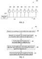
- FIG. 3is a flow chart illustrating a method for monitoring a street lighting subsystem to determine a fault in a light source, in accordance with aspects of the present specification.
- various embodiments of exemplary systems and methods for determining a malfunction in one or more light sources in a street lighting subsystemare presented.
- light emitted from a light sourceis evaluated and the condition of the light source is determined accordingly.
- the existing power line of the street lighting subsystemmay be utilized for monitoring the condition of the light source, which in turn substantially reduces the cost of operating and maintaining the street lighting subsystem.
- FIG. 1a diagrammatical representation 100 of a system for monitoring a street lighting subsystem 101 , in accordance with aspects of the present specification, is depicted.
- the exemplary system 100may be used for identifying a fault or malfunction in one or more light sources in the street lighting subsystem 101 .
- the dimming of the intensity of a light source or a burnt out light sourcemay be indicative of a faulty light source.
- the system 100may include a diagnostic unit 106 .
- the street lighting subsystem 101may be communicatively coupled to the diagnostic unit 106 .
- the street lighting subsystem 101may include one or more luminaires that are communicatively coupled to the diagnostic unit 106 .
- the street lighting subsystem 101is depicted with a single luminaire 102 .
- the street lighting subsystem 101may include any number of luminaires to illuminate a geographic location, and is not limited to one luminaire 102 as shown in FIG. 1 .
- a plurality of luminairesmay be linearly or non-linearly arranged along a street to provide adequate lighting to pedestrians and motorized and non-motorized vehicle operators and passengers on the street.
- the luminaire 102may be coupled to the diagnostic unit 106 via a power cable 116 that is used for supplying electrical power to the luminaire 102 .
- the luminaire 102may include a light source 104 , a monitoring device 108 , and a lamp post 110 .
- the light source 104is operatively coupled to the monitoring device 108 .
- the light source 104may be a light-emitting diode (LED) source that emits light to illuminate a location surrounding the luminaire 102 .
- the monitoring device 108is operatively coupled to the lamp post 110 .
- the monitoring device 108may be configured to determine a working condition of the light source 104 .
- the monitoring device 108may be configured to determine the working condition of the light source 104 by measuring an amount of light emitted from the light source 104 .
- the monitoring device 108may be detachably coupled to the light source 104 .
- the monitoring device 108 and the light source 104may be disposed in a single unit.
- the monitoring device 108 along with the light source 104may be mounted on the lamp post 110 .
- the lamp post 110may be used to elevate the light source 104 to a determined height from the ground.
- the monitoring device 108may include a sensing unit 112 and a squawk unit 114 .
- the sensing unit 112 and the squawk unit 114may be electrically coupled to each other. Further, the sensing unit 112 may be positioned proximate to the light source 104 .
- the sensing unit 112may be used to determine an amount of light emitted from the light source 104 .
- the sensing unit 112may include one or more photocells that are used to sense the light emitted from the light source 104 . It may be noted that the sensing unit 112 may include any type of photo-detector to detect the light emitted from the light source 104 .
- the sensing unit 112may also be configured to determine and/or monitor an intensity of the light emitted from the light source 104 .
- the sensing unit 112may be configured to generate an electrical signal that is representative of the emitted light from the light source 104 . It may be noted that if the amount of light emitted by the light source 104 is below a threshold value, it may be representative of a fault or malfunction in the light source 104 . Accordingly, the sensing unit 112 may be configured to compare this electrical signal with the threshold value to determine whether the emitted light from the light source 104 is below the threshold value. If the emitted light is below the threshold value, the sensing unit 112 may be configured to generate a triggering signal. Additionally, the sensing unit 112 may be configured to communicate the triggering signal to the squawk unit 114 .
- the squawk unit 114may be configured to generate a squawk signal. Further, the squawk unit 114 may be configured to communicate the generated squawk signal to the diagnostic unit 106 .
- the squawk signalmay include one or more tones that are generated at a determined frequency to indicate that the light source 104 is malfunctioning.
- the squawk unit 114may be configured to continuously generate the squawk signal until the electrical power supply to the light source 104 is decoupled.
- the squawk signalmay include an address associated with the luminaire 102 .
- This addressmay be utilized by the diagnostic unit 106 to identify the luminaire 102 among a plurality of luminaires (not show in FIG. 1 ) in the street.
- the squawk signalmay include the determined amount of light emitted from the light source 104 and the address associated with the luminaire 102 . This information may be used by the diagnostic unit 106 to determine a type of fault that has occurred in the luminaire 102 .
- the squawk unit 114may be configured to communicate the squawk signal to the diagnostic unit 106 over the existing power cable 116 that is used for supplying the electrical power to the light source 104 .
- the squawk unit 114may be configured to transmit the squawk signal having multiple tones to overcome multipath effects and/or attenuation effects in the power cable 116 .
- use of the existing power cable 116 to transmit the squawk signalaids in reducing the cost involved in maintaining and operating the system 100 .
- the squawk unit 114may be configured to aerially communicate the squawk signal to the diagnostic unit 106 .
- This squawk signalmay also be referred to as a sound-based squawk signal.
- the squawk unit 114may be configured to emit or radiate the squawk signal at an ultrasonic or infrasonic frequency, thereby minimizing any nuisance to the pedestrians and/or motorists on the street. It may be noted that the squawk signal may be emitted at any frequency, and is not limited to the ultrasonic or infrasonic frequency.
- the diagnostic unit 106may be configured to aerially receive this squawk signal.
- the diagnostic unit 106may be configured to analyze the squawk signal to determine the operating condition of the light source 104 . Particularly, the diagnostic unit 106 may be configured to identify the one or more tones in the squawk signal that may be present along with the noise or other signals. In one example, the diagnostic unit 106 may employ one or more narrowband filtering techniques to identify the tones in the squawk signal.
- the diagnostic unit 106may be configured to transmit a termination signal to the squawk unit 114 .
- the termination signalmay include an address associated with the luminaire 102 .
- the squawk unit 114may receive the termination signal only if the address associated with a corresponding luminaire is present in the termination signal.
- the squawk unit 114may be configured to decouple/stop the electrical power supply to the light source 104 .
- the diagnostic unit 106may be configured to transmit the termination signal to an addressable switch 118 disposed in the squawk unit 114 .
- the addressable switch 118 in the squawk unit 114may be configured to decouple the electrical power to the light source 104 based on the received termination signal. Also, in one embodiment, the diagnostic unit 106 may be configured to communicate a fault signal to an operator device, where the fault signal is indicative of a faulty light source 104 in the street lighting system 100 .
- the exemplary system 100may be configured to effectively identify a fault or malfunction in the light source 104 and decouple electrical power supply to the faulty light source 104 . Also, a signal indicative of a desired replacement and/or repair of a faulty light source 104 may be communicated to the operator.
- the street lighting subsystem 201may include a plurality of luminaires 202 , 204 , 206 , 208 , 210 , 212 , 214 , 216 that are communicatively coupled to a diagnostic unit 218 . It may be noted that each of the plurality of luminaires 202 - 216 may be representative of the luminaire 102 shown in FIG. 1 . Also, each of the plurality of luminaires 202 - 216 may include a corresponding light source, a sensing unit, and a squawk unit.
- the light sourceis configured to emit light and the sensing unit is used to monitor the light source to determine whether the emitted light is below a threshold value. Further, the squawk unit is used to generate a squawk signal if the emitted light is below the threshold value. Also, the diagnostic unit 218 may be representative of the diagnostic unit 106 shown in FIG. 1 .
- the street lighting subsystem 201includes the luminaires 202 - 216 that are coupled to a power line 220 . It may be noted that the street lighting system 201 may include any number of luminaires, and is not limited to the number of luminaires shown in FIG. 2 . Also, the diagnostic unit 218 may be connected to the same power line 220 to which the luminaires 202 - 216 are connected.
- the associated squawk unitmay be configured to transmit a squawk signal from the faulty luminaire to the diagnostic unit 218 .
- the diagnostic unit 218may continuously receive the squawk signal from the luminaire 202 until the electrical power supply to that luminaire 202 is decoupled.
- the luminaire 202may transmit the squawk signal to the diagnostic unit 218 until a termination signal is received from the diagnostic unit 218 , and the electrical power supply to the light source in the luminaire 202 is decoupled via use of an addressable switch in the luminaire 202 .
- the diagnostic unit 218may be configured to process the squawk signal that may include noise and/or other signals.
- the diagnostic unit 218may be configured to process the squawk signal to recognize one or more tones in the squawk signal.
- the one or more tonesmay be at a determined frequency.
- the diagnostic unit 218may receive different types of signals from external devices including the luminaires 202 - 216 , thereby enhancing the complexity of identification of the squawk signal among these signals by the diagnostic unit 218 . Therefore, the diagnostic unit 218 may be configured to process each of these signals to verify the presence of one or more tones in the signals.
- the diagnostic unit 218may be configured to identify the corresponding signal as a squawk signal.
- the diagnostic unit 218may employ narrowband filtering techniques to identify the one or more tones in the squawk signal.
- the squawk signalsmay also include an address of a corresponding luminaire. Accordingly, the diagnostic unit 218 may be configured to extract this address to identify the luminaire that is malfunctioning, thereby allowing timely identification of a malfunctioning luminaire.
- the squawk signalmay be affected/diminished by standing wave interference on the power line 220 . However, by including the plurality of tones in the squawk signal, the squawk signal may overcome the ability of standing wave interference on the power line to diminish the squawk signal.
- the luminaires 202 - 216may be configured to transmit the squawk signals that do not include the address of a corresponding luminaire.
- one or more malfunctioning luminairesmay transmit substantially similar squawk signals to the diagnostic unit 218 .
- the diagnostic unit 218may be configured to identify one or more malfunctioning luminaire using the squawk signals. More particularly, in this embodiment, the diagnostic unit 218 may be configured to identify the one or more malfunctioning luminaires by using a sequential testing protocol. As per the sequential testing protocol, the diagnostic unit 218 may be configured to sequentially deactivate individual luminaires or a group of luminaires in the plurality of luminaires for a determined time period.
- the diagnostic unit 218may be configured to verify receipt of the squawk signals from the individual luminaires or the group of luminaires. If no squawk signals are received, then the diagnostic unit 218 may be configured to confirm that the deactivated luminaires include one or more malfunctioning luminaires.
- the diagnostic unit 218may be configured to confirm that this single luminaire is a malfunctioning luminaire. In a similar manner, if no squawk signals are received after deactivating a group of luminaires, then the diagnostic unit 218 may be configured to confirm that one or more luminaires in this group of luminaires are malfunctioning. Also, the diagnostic unit 218 may further be configured to intelligently divide the luminaires in the group of luminaires by sequentially deactivating corresponding luminaires. Further, this refinement may continue until one or more malfunctioning luminaires are identified.
- the street lighting subsystem 201includes eight luminaires 202 - 216 that are coupled to the diagnostic unit 218 via the power line 220 . If the diagnostic unit 218 receives one or more squawk signals, the diagnostic unit 218 may be configured to initiate the sequential testing protocol. In one example, the diagnostic unit 218 may be configured to deactivate the luminaires 202 , 204 , 206 , 208 and verify whether the squawk signals are still being received by the diagnostic unit 218 . If it is determined that the diagnostic unit 218 continues to receive the squawk signals, the diagnostic unit 218 may deactivate the luminaires 210 , 212 and activate the luminaires 202 - 208 .
- the diagnostic unit 218may be configured to determine that one or both of the luminaires 210 , 212 are malfunctioning. In order to determine if one or both the luminaires 210 , 212 are malfunctioning, the diagnostic unit 218 may be configured to deactivate the luminaire 210 and activate the luminaire 212 . If the diagnostic unit 218 does not receive any squawk signals, then the diagnostic unit 218 may be configured to confirm that the luminaire 210 is malfunctioning. Otherwise, the diagnostic unit 218 may be configured to confirm that the luminaire 212 is malfunctioning.
- the diagnostic unit 218may include a sound detector configured to detect the squawk signals that are emitted or radiated into air by the one or more luminaires 202 - 216 . More particularly, the diagnostic unit 218 having the sound detector may be mounted on a vehicle. Further, the vehicle may be driven in the vicinity of the luminaires 202 - 216 and the diagnostic unit 218 may be configured to monitor for the presence of a sound-based squawk signal and its associated luminaire. In one embodiment, the vehicle may be driven in the vicinity of the luminaires 202 - 216 and the diagnostic unit 218 may be configured to individually activate and deactivate each of the luminaires 202 - 216 .
- the diagnostic unit 218may be configured to activate each of the luminaires 202 - 216 by providing the electrical power supply to a corresponding luminaire. Furthermore, the diagnostic unit 218 may be configured to deactivate each of the luminaires 202 - 216 by decoupling the electrical power supply to the corresponding luminaire. Also, the sound detector in the diagnostic unit 218 may be configured to determine whether the radiation of squawk signals is terminated by deactivating a respective luminaire. This process of activating and deactivating each luminaire is continued until the diagnostic unit 218 identifies one or more malfunctioning luminaires in the system 200 . In one another embodiment, the diagnostic unit 218 may be configured to notify an operator that one or more luminaires are malfunctioning. Also, the diagnostic unit 218 may be configured to notify the operator to repair or replace the one or more malfunctioning luminaires.
- FIG. 3a flow chart 300 illustrating a method for identifying a faulty luminaire among a plurality of luminaires in a street lighting subsystem, in accordance with aspects of the present specification, is depicted.
- the methodbegins at step 302 , where an amount of light emitted from a light source 104 in a luminaire 102 of the street lighting subsystem 100 is sensed or measured.
- a sensing unit 112 that is disposed in a monitoring device 108is used to measure the amount of light emitted from the light source 104 .
- the sensing unit 112may include one or more photo detectors to sense the light emitted by the light source 104 .
- a squawk signalmay be generated based on the amount of light emitted from the light source.
- a squawk unit 114 in the monitoring device 108is used to generate the squawk signal.
- the sensing unit 112may be configured to verify whether the amount of light emitted from the light source is below a threshold value. If the amount of light emitted from the light source is below the threshold value, the sensing unit 112 may be configured to transmit a triggering signal to the squawk unit 114 . Further, in response to receiving the triggering signal, the squawk unit 114 may be configured to generate the squawk signal that is indicative of a fault or malfunction in the light source.
- the squawk signalmay be communicated to a diagnostic unit 106 .
- the squawk unit 114may be configured to communicate the squawk signal to the diagnostic unit 106 .
- the squawk signalmay be transmitted by the squawk unit 114 via a power cable 116 that is used to operatively couple the light source 104 and the diagnostic unit 106 .
- the squawk unit 114may aerially transmit the squawk signal towards the diagnostic unit 106 .
- the diagnostic unit 106may use one or more sound detectors to receive the aerially transmitted squawk signals.
- the diagnostic unit 106may be configured to process the squawk signal to detect a fault or malfunctioning light source 104 .
- a termination signalmay be generated by the diagnostic unit 106 .
- the diagnostic unit 106may be configured to generate the termination signal in response to the squawk signal received by the diagnostic unit 106 from the squawk unit 114 .
- the diagnostic unit 106may also be configured to communicate the termination signal to the squawk unit 114 .
- the termination signalmay be used to decouple electrical power supply to the light source 104 that is malfunctioning.
- the diagnostic unit 106 , 218may also be configured to detect a fault or a malfunctioning light source 104 by using a sound detector. More particularly, the sound detector may be included in the diagnostic unit 106 , 218 that is mounted on a vehicle. Further, the vehicle may be driven in the vicinity of the luminaires 202 - 216 and the diagnostic unit 106 , 218 may be configured to monitor for the presence of a sound-based squawk signal and an associated luminaire. In another embodiment, the vehicle may be driven in the vicinity of the luminaires 202 - 216 and the diagnostic unit 106 , 218 may be configured to individually activate and deactivate each of the luminaires 202 - 216 .
- the diagnostic unit 106 , 218may be configured to activate each of the luminaires 202 - 216 by providing the electrical power supply to a corresponding luminaire. Furthermore, the diagnostic unit 106 , 218 may be configured to deactivate each of the luminaires 202 - 216 by decoupling the electrical power supply to the corresponding luminaire. Also, the sound detector in the diagnostic unit 106 , 218 may be configured to determine whether the radiation of squawk signals is terminated by deactivating a respective luminaire. This process of activating and deactivating the luminaires is continued until the diagnostic unit 106 , 218 identifies one or more malfunctioning luminaires in the system 200 .
- the electrical power supply to the light source 104is decoupled based on the received termination signal.
- the squawk unit 114may include an addressable switch 118 that is used to decouple the electrical power supply to the light source 104 when the termination signal is received form the diagnostic unit 106 .
- the diagnostic unit 106may be configured to inform an operator to rectify or replace the light source 104 that is malfunctioning.
- the various embodiments of the exemplary system and methodaid in identifying one or more faulty luminaires among a plurality of luminaires in the street lighting subsystem. Also, the system aids in terminating the electrical power supply to a light source, which in turn saves electrical power in the street lighting subsystem. Also, since the system utilizes the existing power cables for communicating signals between the luminaires and the diagnostic unit, the cost involved in operating and maintaining the system is substantially reduced.
Landscapes
- Circuit Arrangement For Electric Light Sources In General (AREA)
Abstract
Description
Claims (15)
Priority Applications (1)
| Application Number | Priority Date | Filing Date | Title |
|---|---|---|---|
| US14/484,300US9420674B2 (en) | 2013-11-21 | 2014-09-12 | System and method for monitoring street lighting luminaires |
Applications Claiming Priority (2)
| Application Number | Priority Date | Filing Date | Title |
|---|---|---|---|
| US201361907133P | 2013-11-21 | 2013-11-21 | |
| US14/484,300US9420674B2 (en) | 2013-11-21 | 2014-09-12 | System and method for monitoring street lighting luminaires |
Publications (2)
| Publication Number | Publication Date |
|---|---|
| US20150137684A1 US20150137684A1 (en) | 2015-05-21 |
| US9420674B2true US9420674B2 (en) | 2016-08-16 |
Family
ID=53172606
Family Applications (1)
| Application Number | Title | Priority Date | Filing Date |
|---|---|---|---|
| US14/484,300ActiveUS9420674B2 (en) | 2013-11-21 | 2014-09-12 | System and method for monitoring street lighting luminaires |
Country Status (1)
| Country | Link |
|---|---|
| US (1) | US9420674B2 (en) |
Cited By (4)
| Publication number | Priority date | Publication date | Assignee | Title |
|---|---|---|---|---|
| US9872361B1 (en) | 2017-06-13 | 2018-01-16 | General Electric Company | Networked light control system and method |
| US10321544B1 (en) | 2018-08-30 | 2019-06-11 | International Business Machines Corporation | Acoustics-based street light control |
| US11510298B1 (en) | 2022-02-24 | 2022-11-22 | Bnsf Railway Company | Smart lamp system and method |
| US11943852B2 (en) | 2022-02-24 | 2024-03-26 | Bnsf Railway Company | System and method for railroad smart flasher lamps |
Families Citing this family (4)
| Publication number | Priority date | Publication date | Assignee | Title |
|---|---|---|---|---|
| US9622323B2 (en)* | 2013-11-21 | 2017-04-11 | General Electric Company | Luminaire associate |
| US10104745B2 (en) | 2016-03-18 | 2018-10-16 | General Electric Company | Power handling system and method |
| US11794796B2 (en)* | 2018-05-08 | 2023-10-24 | TekTracking, LLC | System and method to ensure signal light integrity and viewability |
| US11509130B2 (en)* | 2021-02-10 | 2022-11-22 | Qualcomm Incorporated | Disconnection arc prevention in cable-supplied power connection |
Citations (153)
| Publication number | Priority date | Publication date | Assignee | Title |
|---|---|---|---|---|
| US4704610A (en) | 1985-12-16 | 1987-11-03 | Smith Michel R | Emergency vehicle warning and traffic control system |
| US5014052A (en) | 1983-04-21 | 1991-05-07 | Bourse Trading Company, Ltd. | Traffic signal control for emergency vehicles |
| US5199044A (en) | 1990-05-22 | 1993-03-30 | Tokimec Inc. | System for detecting position of object having data carrier |
| US5243185A (en) | 1992-07-31 | 1993-09-07 | Loral Aerospace Corp. | Apparatus and method for ice detection |
| US5345232A (en) | 1992-11-19 | 1994-09-06 | Robertson Michael T | Traffic light control means for emergency-type vehicles |
| US5519725A (en) | 1995-03-20 | 1996-05-21 | General Electric Company | Geometric harmonic modulation (GHM) for combined analog/digital transmissions |
| US5519692A (en) | 1995-03-20 | 1996-05-21 | General Electric Company | Geometric harmonic modulation (GHM)-digital implementation |
| US5526357A (en) | 1991-08-16 | 1996-06-11 | Pinpoint Communications, Inc. | Communication system and method for determining the location of a transponder unit |
| US5563906A (en) | 1995-03-20 | 1996-10-08 | General Electric Company | Method of geometric harmonic modulation (GHM) |
| US5568522A (en) | 1995-03-20 | 1996-10-22 | General Electric Company | Correction of multipath distortion in wideband carrier signals |
| US5568508A (en) | 1995-03-20 | 1996-10-22 | General Electric Company | Interlaced geometric harmonic modulation |
| US5568509A (en) | 1995-03-20 | 1996-10-22 | General Electric Company | Dynamic code division multiple access communication system |
| US5568507A (en) | 1995-03-20 | 1996-10-22 | General Electric Company | Geometric harmonic modulation (GHM) - analog implementation |
| US5682100A (en) | 1995-09-06 | 1997-10-28 | Electric Power Research Institute Inc. | System and method for locating faults in electric power cables |
| US5761238A (en) | 1996-07-05 | 1998-06-02 | General Electric Company | Transmitted reference spread spectrum communications system |
| US5844949A (en) | 1996-10-09 | 1998-12-01 | General Electric Company | Power line communication system |
| US5852243A (en) | 1997-07-21 | 1998-12-22 | J-Squared, Llc | Method and apparatus for detecting a road pavement surface condition |
| US5903594A (en) | 1997-04-16 | 1999-05-11 | General Electric Company | Power line communications spread spectrum protocol |
| US6011508A (en) | 1997-10-31 | 2000-01-04 | Magnemotion, Inc. | Accurate position-sensing and communications for guideway operated vehicles |
| US6101214A (en) | 1997-04-28 | 2000-08-08 | General Electric Company | Power line communications spread spectrum symbol timing and random phasing |
| US6288632B1 (en) | 1999-12-20 | 2001-09-11 | General Electric Company | Apparatus and method for power line communication (PLC) |
| US6346875B1 (en) | 2000-01-03 | 2002-02-12 | General Electric Company | GHM aggregator |
| US6424250B1 (en) | 1999-03-08 | 2002-07-23 | General Electric Company | Communication system utilizing modified geometric harmonic modulation |
| US6430210B1 (en) | 1999-04-05 | 2002-08-06 | General Electric Company | Receiver for detecting an amplitude modulated signal insinuated on an GHM signal |
| US6433976B1 (en)* | 1999-09-24 | 2002-08-13 | Square D Company | Instantaneous arc fault light detector with resistance to false tripping |
| US6459998B1 (en) | 1999-07-24 | 2002-10-01 | Gary R. Hoffman | Sensing downed power lines |
| US20020141882A1 (en) | 2000-03-29 | 2002-10-03 | Steve Ingistov | Method and apparatus for increasing the efficiency of a multi-stage compressor |
| US6522243B1 (en) | 2001-06-28 | 2003-02-18 | General Electric Company | Geometric harmonic modulation signaling and detection |
| US6659715B2 (en) | 2002-01-17 | 2003-12-09 | Siemens Aktiengesellschaft | Axial compressor and method of cleaning an axial compressor |
| US6717660B1 (en) | 2000-08-01 | 2004-04-06 | Safe Passage Systems Corporation | System for monitoring and testing of light sources |
| EP1437270A1 (en) | 2003-01-11 | 2004-07-14 | Grupo MSG 2000, S.A. | System and method for vehicle identification |
| GB2403357A (en) | 2003-06-25 | 2004-12-29 | Lighthouse Data Man Ltd | Monitoring system for public lighting |
| US20050017647A1 (en)* | 2003-07-23 | 2005-01-27 | Huang Shih-Chung | Back-lighted control and protection device for multi-lamp LCD |
| WO2005029437A2 (en) | 2003-09-15 | 2005-03-31 | California Institute Of Technology | Forwarding system for long-range preemption and corridor clearance for emergency response |
| US20050187701A1 (en) | 2004-02-23 | 2005-08-25 | Baney Douglas M. | Traffic communication system |
| US6943668B2 (en) | 2001-06-26 | 2005-09-13 | General Electric Company | Apparatus and method for reconfiguring a power line communication system |
| JP2005248607A (en) | 2004-03-05 | 2005-09-15 | Tokai Univ | Road facility |
| KR20060008967A (en) | 2003-05-07 | 2006-01-27 | 코닌클리케 필립스 일렉트로닉스 엔.브이. | Accident detection system |
| US7175082B2 (en) | 2003-03-20 | 2007-02-13 | Seiko Epson Corporation | Contactless data communication system, position information management system, contactless identification tag, data communication system, contactless identification tag control program, and data communication system control program |
| US7248149B2 (en) | 2003-10-06 | 2007-07-24 | California Institute Of Technology | Detection and enforcement of failure-to-yield in an emergency vehicle preemption system |
| US20070201540A1 (en) | 2006-02-14 | 2007-08-30 | Berkman William H | Hybrid power line wireless communication network |
| US20070229250A1 (en) | 2006-03-28 | 2007-10-04 | Wireless Lighting Technologies, Llc | Wireless lighting |
| US7294977B1 (en) | 2006-01-13 | 2007-11-13 | Holtkotter International, Inc. | Lamp dimming system and methods |
| US20080037241A1 (en) | 2006-04-21 | 2008-02-14 | Erco Leuchten Gmbh | Light fixture |
| US7333903B2 (en) | 2005-09-12 | 2008-02-19 | Acuity Brands, Inc. | Light management system having networked intelligent luminaire managers with enhanced diagnostics capabilities |
| US20080072766A1 (en) | 2006-09-14 | 2008-03-27 | Bunn-O-Matic Corporation | Brewer with air evacuation |
| US20080122642A1 (en) | 2006-11-02 | 2008-05-29 | Radtke William O | Power Line Communication and Power Distribution Parameter Measurement System and Method |
| US20080150757A1 (en) | 2006-12-20 | 2008-06-26 | Michael Cole Hutchison | Traffic signal with integrated sensors |
| US7418346B2 (en) | 1997-10-22 | 2008-08-26 | Intelligent Technologies International, Inc. | Collision avoidance methods and systems |
| US20080238720A1 (en) | 2007-03-30 | 2008-10-02 | Jin-Shyan Lee | System And Method For Intelligent Traffic Control Using Wireless Sensor And Actuator Networks |
| US20090002982A1 (en) | 2007-06-29 | 2009-01-01 | Foxsemicon Integrated Technology, Inc. | Outdoor lighting system with controlled luminance |
| JP2009025209A (en) | 2007-07-20 | 2009-02-05 | Panasonic Electric Works Co Ltd | Location information system |
| US20090034258A1 (en) | 2007-07-30 | 2009-02-05 | Topco Technologies Corp. | Illumination system |
| US20090066540A1 (en) | 2007-09-07 | 2009-03-12 | Dimitri Marinakis | Centralized route calculation for a multi-hop streetlight network |
| JP2009103497A (en) | 2007-10-22 | 2009-05-14 | Churyo Eng Kk | Running locus computing device of mobile station by independent gps positioning having initial position correction function |
| US20090120299A1 (en) | 2005-01-06 | 2009-05-14 | Bunn-O-Matic Corporation | Line Pressure Brewer |
| US20090164174A1 (en) | 2007-12-21 | 2009-06-25 | James Bears | Solar system automatic sizing and failure identification on location using resident gps receiver |
| US20090158739A1 (en) | 2007-12-21 | 2009-06-25 | Hans-Peter Messmer | Gas turbine systems and methods employing a vaporizable liquid delivery device |
| US7580705B2 (en) | 2005-10-11 | 2009-08-25 | Tropos Networks, Inc. | Remote wireless access node control |
| US20090214198A1 (en)* | 2008-02-21 | 2009-08-27 | Fujitsu Limited | Optical transmitter |
| US20090297156A1 (en) | 2002-10-24 | 2009-12-03 | Nakagawa Laboratories, Inc. | Illuminative light communication system, lighting device and illuminative light source |
| US7629899B2 (en) | 1997-10-22 | 2009-12-08 | Intelligent Technologies International, Inc. | Vehicular communication arrangement and method |
| EP2131630A2 (en) | 2008-06-06 | 2009-12-09 | Tecnologie e Servizi Innovativi - T.S.I. S.r.l. | Smart led street lamp designed for saving energy, monitored and controlled by a remote control center |
| WO2009148466A1 (en) | 2008-06-05 | 2009-12-10 | Relume Technologies, Inc. | Networked light control system |
| US7646330B2 (en) | 2005-03-14 | 2010-01-12 | Alfred E. Mann Foundation For Scientific Research | System and method for locating objects and communicating with the same |
| US20100115093A1 (en) | 2007-05-04 | 2010-05-06 | Patrick Jeremy Rice | Monitoring apparatus and system |
| WO2010079388A1 (en) | 2009-01-07 | 2010-07-15 | Koninklijke Philips Electronics N.V. | Intelligent controllable lighting networks and schemata therefore |
| KR100986279B1 (en) | 2010-06-30 | 2010-10-07 | 전영일 | Method for control intelligent traffic signal and system thereof |
| US7817063B2 (en) | 2005-10-05 | 2010-10-19 | Abl Ip Holding Llc | Method and system for remotely monitoring and controlling field devices with a street lamp elevated mesh network |
| US7834555B2 (en) | 2005-06-30 | 2010-11-16 | Streetlight Intelligence, Inc. | Method and system for luminance characterization |
| US20100295943A1 (en) | 2006-10-20 | 2010-11-25 | Kt Corporation | Real-time rfid positioning system and method, repeater installation method therefor, position confirmation service system using the same |
| US20100295475A1 (en) | 2008-04-14 | 2010-11-25 | Digital Lumens, Inc. | Power Management Unit with Ballast Interface |
| US20100295473A1 (en) | 2008-04-14 | 2010-11-25 | Digital Lumens, Inc. | Power Management Unit with Sensor Logging |
| US20100296285A1 (en) | 2008-04-14 | 2010-11-25 | Digital Lumens, Inc. | Fixture with Rotatable Light Modules |
| US20100295474A1 (en) | 2008-04-14 | 2010-11-25 | Digital Lumens, Inc. | Power Management Unit with Modular Sensor Bus |
| US20100295482A1 (en) | 2009-04-14 | 2010-11-25 | Digital Lumens, Inc. | Power Management Unit with Multi-Input Arbitration |
| US20100301774A1 (en) | 2008-04-14 | 2010-12-02 | Digital Lumens, Inc. | Power Management Unit with Automatic Output Configuration |
| US20100301771A1 (en) | 2008-04-14 | 2010-12-02 | Digital Lumens, Inc. | Power Management Unit with Power Source Arbitration |
| US20100301773A1 (en) | 2009-04-14 | 2010-12-02 | Digital Lumens, Inc. | Fixture with Individual Light Module Dimming |
| US20100301770A1 (en) | 2008-04-14 | 2010-12-02 | Digital Lumens, Inc. | Power Management Unit with Lifetime Prediction |
| US20100301768A1 (en) | 2008-04-14 | 2010-12-02 | Digital Lumens, Inc. | Power Management Unit with Real Time Clock |
| US20100301834A1 (en) | 2009-04-14 | 2010-12-02 | Digital Lumens, Inc. | Low-Cost Power Measurement Circuit |
| US20100302779A1 (en) | 2008-04-14 | 2010-12-02 | Digital Lumens, Inc. | Fixture with Replaceable Light Bars |
| US7855376B2 (en) | 2005-12-19 | 2010-12-21 | Institut National D'optique | Lighting system and method for illuminating and detecting object |
| US20110001626A1 (en) | 2008-02-22 | 2011-01-06 | Tri-Concept Technology Limited | Apparatus and system for led street lamp monitoring and control |
| US20110001436A1 (en) | 2008-04-14 | 2011-01-06 | Digital Lumens, Inc. | Power Management Unit with Light Module Identification |
| US20110001438A1 (en) | 2008-04-14 | 2011-01-06 | Digital Lumens, Inc. | Power Management Unit with Temperature Protection |
| US7876864B2 (en) | 2007-05-03 | 2011-01-25 | Motorola, Inc. | Method and device for enhancing signal detection in a frequency selective fading channel |
| US20110043035A1 (en) | 2009-03-19 | 2011-02-24 | Jose Luiz Yamada | Apparatus and methods for controlling light fixtures and electrical appliances |
| US7899621B2 (en) | 1997-10-22 | 2011-03-01 | Intelligent Technologies International, Inc. | Accident avoidance system |
| US7912645B2 (en) | 1997-10-22 | 2011-03-22 | Intelligent Technologies International, Inc. | Information transfer arrangement and method for vehicles |
| US20110069960A1 (en) | 2008-09-05 | 2011-03-24 | Knapp David J | Systems and methods for visible light communication |
| US20110095867A1 (en) | 2009-04-28 | 2011-04-28 | Rizwan Ahmad | Remote monitoring and control of led based street lights |
| US20110115384A1 (en) | 2008-07-21 | 2011-05-19 | Koninklijke Philips Electronics N.V. | Method of setting up a luminaire and luminaire to apply the method |
| US20110140950A1 (en) | 2008-06-18 | 2011-06-16 | Saab Ab | Validity check of vehicle position information transmitted over a time-synchronized data link |
| US7983685B2 (en) | 2006-12-07 | 2011-07-19 | Innovative Wireless Technologies, Inc. | Method and apparatus for management of a global wireless sensor network |
| US7983836B2 (en) | 1997-10-22 | 2011-07-19 | Intelligent Technologies International, Inc. | Vehicle-traffic control device communication techniques |
| US20110215736A1 (en) | 2010-03-08 | 2011-09-08 | Horbst Joseph E | Method and system for lighting control and monitoring |
| US20110227584A1 (en) | 2010-03-16 | 2011-09-22 | Bernhard Beck | Insulation test method for large-scale photovoltaic systems |
| WO2011142516A1 (en) | 2010-05-11 | 2011-11-17 | (주)한동테크 | Remotely monitored streetlight system |
| US20120062123A1 (en) | 2010-09-09 | 2012-03-15 | Jarrell John A | Managing Light System Energy Use |
| US8140276B2 (en) | 2008-02-27 | 2012-03-20 | Abl Ip Holding Llc | System and method for streetlight monitoring diagnostics |
| US8138690B2 (en) | 2008-04-14 | 2012-03-20 | Digital Lumens Incorporated | LED-based lighting methods, apparatus, and systems employing LED light bars, occupancy sensing, local state machine, and meter circuit |
| US20120086560A1 (en) | 2010-10-07 | 2012-04-12 | General Electric Company | Outdoor lighting system |
| US20120086561A1 (en) | 2010-10-07 | 2012-04-12 | General Electric Company | Outdoor lighting system |
| US20120126721A1 (en) | 2010-11-19 | 2012-05-24 | Lumination Llc | Gps-based lighting control system |
| US20120136485A1 (en) | 2010-11-19 | 2012-05-31 | Weber Theodore E | Control System and Method for Managing Wireless and Wired Components |
| US20120140748A1 (en) | 2010-12-07 | 2012-06-07 | John Carruthers | End point control method |
| US20120154239A1 (en) | 2010-12-15 | 2012-06-21 | Bridgewave Communications, Inc. | Millimeter wave radio assembly with a compact antenna |
| US20120163826A1 (en) | 2009-09-14 | 2012-06-28 | Koninklijke Philips Electronics N.V. | Coded light transmission and reception |
| WO2012090142A2 (en) | 2010-12-28 | 2012-07-05 | Koninklijke Philips Electronics N.V. | Outdoor lighting network control system |
| US8227995B2 (en) | 2007-10-12 | 2012-07-24 | Koninklijke Philips Electronics N.V. | Sensing coded light using retro reflectors |
| US8232745B2 (en) | 2008-04-14 | 2012-07-31 | Digital Lumens Incorporated | Modular lighting systems |
| US20120209505A1 (en) | 1999-03-11 | 2012-08-16 | American Vehicular Sciences | Vehicle Airbag System and Method |
| US20120218101A1 (en) | 2011-02-24 | 2012-08-30 | Ford Timothy D F | Situational marking and awareness tag (smart) beacon, system and method |
| US8260537B2 (en) | 1997-10-22 | 2012-09-04 | Intelligent Technologies International, Inc. | Method for modifying an existing vehicle on a retrofit basis to integrate the vehicle into an information exchange system |
| US20120230696A1 (en) | 2000-11-15 | 2012-09-13 | Federal Law Enforcement Development Services, Inc. | Led light communication system |
| US8274373B2 (en) | 1996-11-29 | 2012-09-25 | X-Cyte, Inc. | Dual mode transmitter-receiver and decoder for RF transponder tags |
| US20120245880A1 (en) | 2011-03-25 | 2012-09-27 | Thomas & Betts International, Inc. | Testing and monitoring an electrical system |
| US20120256777A1 (en) | 2011-04-07 | 2012-10-11 | United States Department of Homeland Security | Method for Identifying Materials Using Dielectric Properties through Active Millimeter Wave Illumination |
| US20120262304A1 (en) | 2011-04-13 | 2012-10-18 | Criptonic Energy Solutions, Inc. | Portable traffic signaling system |
| WO2012140152A1 (en) | 2011-04-12 | 2012-10-18 | Aleksander Gerbec | Network comprising nodes associated with outdoor lighting devices |
| EP2521426A1 (en) | 2011-04-28 | 2012-11-07 | Helvar Oy Ab | Device and method for controlling lighting control system |
| US20120286673A1 (en) | 2011-05-15 | 2012-11-15 | Lighting Science Group Corporation | Configurable environmental condition sensing luminaire, system and associated methods |
| US20120308239A1 (en) | 2011-06-03 | 2012-12-06 | Sheth Samir S | Active Tracking for Free-Space Optical Communication Systems |
| US20120309293A1 (en) | 2011-06-03 | 2012-12-06 | Thomas Kummetz | Mobile repeater system and method having geophysical location awareness without use of gps |
| US20120321321A1 (en) | 2011-06-14 | 2012-12-20 | Scott Riesebosch | Methods of communication utilizing an led lamp |
| US20120323474A1 (en) | 1998-10-22 | 2012-12-20 | Intelligent Technologies International, Inc. | Intra-Vehicle Information Conveyance System and Method |
| US8339069B2 (en) | 2008-04-14 | 2012-12-25 | Digital Lumens Incorporated | Power management unit with power metering |
| US8368321B2 (en) | 2008-04-14 | 2013-02-05 | Digital Lumens Incorporated | Power management unit with rules-based power consumption management |
| US8373362B2 (en) | 2008-04-14 | 2013-02-12 | Digital Lumens Incorporated | Methods, systems, and apparatus for commissioning an LED lighting fixture with remote reporting |
| US20130044488A1 (en) | 2011-08-17 | 2013-02-21 | G. Albert Hreish | Combination Lamp and Wireless Network Access System |
| US8384312B2 (en) | 2009-06-03 | 2013-02-26 | Ge Investment Co., Ltd. | Power distribution system for supplying electrical power to a plurality of lighting units |
| US20130057158A1 (en) | 2010-03-01 | 2013-03-07 | Led Roadway Lighting Ltd. | Gps-based streetlight wireless command and control system |
| US20130101003A1 (en) | 2011-10-24 | 2013-04-25 | Texas Instruments Incorporated | Relative Phase Detection in Power Line Communications Networks |
| US8436748B2 (en) | 2007-06-18 | 2013-05-07 | Leddartech Inc. | Lighting system with traffic management capabilities |
| US8441214B2 (en) | 2009-03-11 | 2013-05-14 | Deloren E. Anderson | Light array maintenance system and method |
| US8442403B2 (en) | 2008-03-02 | 2013-05-14 | Lumenetix, Inc. | Lighting and control systems and methods |
| US8456325B1 (en) | 2010-06-25 | 2013-06-04 | Tomar Electronics, Inc. | Networked streetlight systems and related methods |
| US20130140995A1 (en) | 2011-12-05 | 2013-06-06 | Morgan Jones | Determination of lighting contributions for light fixtures using optical bursts |
| US20130172012A1 (en) | 2010-08-02 | 2013-07-04 | Tridonic Gmbh & Co. Kg | Method, Apparatus and System for Addressing Operating Devices for Luminaires |
| US20130169468A1 (en) | 2011-12-30 | 2013-07-04 | Flir Systems, Inc. | Radar system and related methods |
| US20130181636A1 (en) | 2012-01-17 | 2013-07-18 | Cimcon Lighting, Inc. | Streetlight Controllers |
| US20130214697A1 (en) | 2012-02-08 | 2013-08-22 | Radiant Research Limited | Power control system for an illumination system |
| US20130229116A1 (en) | 2010-11-02 | 2013-09-05 | Paulus Thomas Maria Van Zeijl | Lighting system with radar detection |
| US20130257284A1 (en) | 2011-05-12 | 2013-10-03 | LSI Saco Technologies, Inc. | Lighting and Integrated Fixture Control |
| WO2013160791A2 (en) | 2012-04-25 | 2013-10-31 | Koninklijke Philips N.V. | Failure detection in lighting system |
| US20130293117A1 (en) | 2007-06-29 | 2013-11-07 | Orion Energy Systems, Inc. | Outdoor lighting fixtures control systems and methods |
| US20130330172A1 (en) | 2012-06-08 | 2013-12-12 | Alston Ilford Scipio | Method, system and apparatus for enhanced off line compressor and turbine cleaning |
| US20140055439A1 (en)* | 2012-08-21 | 2014-02-27 | Samsung Display Co., Ltd. | Backlight unit and a display apparatus having the same |
| US20140124007A1 (en) | 2012-11-07 | 2014-05-08 | General Electric Company | Offline compressor wash systems and methods |
| US20140175982A1 (en)* | 2012-12-21 | 2014-06-26 | General Electric Company | Fault protection system and method for fluorescent lamp ballasts |
| US8842009B2 (en)* | 2012-06-07 | 2014-09-23 | Mojo Labs, Inc. | Multiple light sensor multiple light fixture control |
- 2014
- 2014-09-12USUS14/484,300patent/US9420674B2/enactiveActive
Patent Citations (157)
| Publication number | Priority date | Publication date | Assignee | Title |
|---|---|---|---|---|
| US5014052A (en) | 1983-04-21 | 1991-05-07 | Bourse Trading Company, Ltd. | Traffic signal control for emergency vehicles |
| US4704610A (en) | 1985-12-16 | 1987-11-03 | Smith Michel R | Emergency vehicle warning and traffic control system |
| US5199044A (en) | 1990-05-22 | 1993-03-30 | Tokimec Inc. | System for detecting position of object having data carrier |
| US5526357A (en) | 1991-08-16 | 1996-06-11 | Pinpoint Communications, Inc. | Communication system and method for determining the location of a transponder unit |
| US5243185A (en) | 1992-07-31 | 1993-09-07 | Loral Aerospace Corp. | Apparatus and method for ice detection |
| US5345232A (en) | 1992-11-19 | 1994-09-06 | Robertson Michael T | Traffic light control means for emergency-type vehicles |
| US5568508A (en) | 1995-03-20 | 1996-10-22 | General Electric Company | Interlaced geometric harmonic modulation |
| US5519692A (en) | 1995-03-20 | 1996-05-21 | General Electric Company | Geometric harmonic modulation (GHM)-digital implementation |
| US5563906A (en) | 1995-03-20 | 1996-10-08 | General Electric Company | Method of geometric harmonic modulation (GHM) |
| US5568522A (en) | 1995-03-20 | 1996-10-22 | General Electric Company | Correction of multipath distortion in wideband carrier signals |
| US5519725A (en) | 1995-03-20 | 1996-05-21 | General Electric Company | Geometric harmonic modulation (GHM) for combined analog/digital transmissions |
| US5568509A (en) | 1995-03-20 | 1996-10-22 | General Electric Company | Dynamic code division multiple access communication system |
| US5568507A (en) | 1995-03-20 | 1996-10-22 | General Electric Company | Geometric harmonic modulation (GHM) - analog implementation |
| US5682100A (en) | 1995-09-06 | 1997-10-28 | Electric Power Research Institute Inc. | System and method for locating faults in electric power cables |
| US5761238A (en) | 1996-07-05 | 1998-06-02 | General Electric Company | Transmitted reference spread spectrum communications system |
| US5844949A (en) | 1996-10-09 | 1998-12-01 | General Electric Company | Power line communication system |
| US8274373B2 (en) | 1996-11-29 | 2012-09-25 | X-Cyte, Inc. | Dual mode transmitter-receiver and decoder for RF transponder tags |
| US5903594A (en) | 1997-04-16 | 1999-05-11 | General Electric Company | Power line communications spread spectrum protocol |
| US6101214A (en) | 1997-04-28 | 2000-08-08 | General Electric Company | Power line communications spread spectrum symbol timing and random phasing |
| US5852243A (en) | 1997-07-21 | 1998-12-22 | J-Squared, Llc | Method and apparatus for detecting a road pavement surface condition |
| US7629899B2 (en) | 1997-10-22 | 2009-12-08 | Intelligent Technologies International, Inc. | Vehicular communication arrangement and method |
| US7983836B2 (en) | 1997-10-22 | 2011-07-19 | Intelligent Technologies International, Inc. | Vehicle-traffic control device communication techniques |
| US7418346B2 (en) | 1997-10-22 | 2008-08-26 | Intelligent Technologies International, Inc. | Collision avoidance methods and systems |
| US8260537B2 (en) | 1997-10-22 | 2012-09-04 | Intelligent Technologies International, Inc. | Method for modifying an existing vehicle on a retrofit basis to integrate the vehicle into an information exchange system |
| US7899621B2 (en) | 1997-10-22 | 2011-03-01 | Intelligent Technologies International, Inc. | Accident avoidance system |
| US7912645B2 (en) | 1997-10-22 | 2011-03-22 | Intelligent Technologies International, Inc. | Information transfer arrangement and method for vehicles |
| US6011508A (en) | 1997-10-31 | 2000-01-04 | Magnemotion, Inc. | Accurate position-sensing and communications for guideway operated vehicles |
| US20120323474A1 (en) | 1998-10-22 | 2012-12-20 | Intelligent Technologies International, Inc. | Intra-Vehicle Information Conveyance System and Method |
| US6424250B1 (en) | 1999-03-08 | 2002-07-23 | General Electric Company | Communication system utilizing modified geometric harmonic modulation |
| US20120209505A1 (en) | 1999-03-11 | 2012-08-16 | American Vehicular Sciences | Vehicle Airbag System and Method |
| US6430210B1 (en) | 1999-04-05 | 2002-08-06 | General Electric Company | Receiver for detecting an amplitude modulated signal insinuated on an GHM signal |
| US6459998B1 (en) | 1999-07-24 | 2002-10-01 | Gary R. Hoffman | Sensing downed power lines |
| US6433976B1 (en)* | 1999-09-24 | 2002-08-13 | Square D Company | Instantaneous arc fault light detector with resistance to false tripping |
| US6288632B1 (en) | 1999-12-20 | 2001-09-11 | General Electric Company | Apparatus and method for power line communication (PLC) |
| US6346875B1 (en) | 2000-01-03 | 2002-02-12 | General Electric Company | GHM aggregator |
| US20020141882A1 (en) | 2000-03-29 | 2002-10-03 | Steve Ingistov | Method and apparatus for increasing the efficiency of a multi-stage compressor |
| US6717660B1 (en) | 2000-08-01 | 2004-04-06 | Safe Passage Systems Corporation | System for monitoring and testing of light sources |
| US20120230696A1 (en) | 2000-11-15 | 2012-09-13 | Federal Law Enforcement Development Services, Inc. | Led light communication system |
| US6943668B2 (en) | 2001-06-26 | 2005-09-13 | General Electric Company | Apparatus and method for reconfiguring a power line communication system |
| US6522243B1 (en) | 2001-06-28 | 2003-02-18 | General Electric Company | Geometric harmonic modulation signaling and detection |
| US6659715B2 (en) | 2002-01-17 | 2003-12-09 | Siemens Aktiengesellschaft | Axial compressor and method of cleaning an axial compressor |
| US20090297156A1 (en) | 2002-10-24 | 2009-12-03 | Nakagawa Laboratories, Inc. | Illuminative light communication system, lighting device and illuminative light source |
| EP1437270A1 (en) | 2003-01-11 | 2004-07-14 | Grupo MSG 2000, S.A. | System and method for vehicle identification |
| US7175082B2 (en) | 2003-03-20 | 2007-02-13 | Seiko Epson Corporation | Contactless data communication system, position information management system, contactless identification tag, data communication system, contactless identification tag control program, and data communication system control program |
| KR20060008967A (en) | 2003-05-07 | 2006-01-27 | 코닌클리케 필립스 일렉트로닉스 엔.브이. | Accident detection system |
| US7460787B2 (en) | 2003-05-07 | 2008-12-02 | Koninklijke Philips Electronics N.V. | Communication system with external synchronisation |
| GB2403357A (en) | 2003-06-25 | 2004-12-29 | Lighthouse Data Man Ltd | Monitoring system for public lighting |
| US20050017647A1 (en)* | 2003-07-23 | 2005-01-27 | Huang Shih-Chung | Back-lighted control and protection device for multi-lamp LCD |
| KR20060102552A (en) | 2003-09-15 | 2006-09-27 | 캘리포니아 인스티튜트 오브 테크놀로지 | Forwarding system for long distance preemption and passage clearance for emergency response |
| WO2005029437A2 (en) | 2003-09-15 | 2005-03-31 | California Institute Of Technology | Forwarding system for long-range preemption and corridor clearance for emergency response |
| US7248149B2 (en) | 2003-10-06 | 2007-07-24 | California Institute Of Technology | Detection and enforcement of failure-to-yield in an emergency vehicle preemption system |
| US20050187701A1 (en) | 2004-02-23 | 2005-08-25 | Baney Douglas M. | Traffic communication system |
| JP2005248607A (en) | 2004-03-05 | 2005-09-15 | Tokai Univ | Road facility |
| US20090120299A1 (en) | 2005-01-06 | 2009-05-14 | Bunn-O-Matic Corporation | Line Pressure Brewer |
| US7646330B2 (en) | 2005-03-14 | 2010-01-12 | Alfred E. Mann Foundation For Scientific Research | System and method for locating objects and communicating with the same |
| US7834555B2 (en) | 2005-06-30 | 2010-11-16 | Streetlight Intelligence, Inc. | Method and system for luminance characterization |
| US7333903B2 (en) | 2005-09-12 | 2008-02-19 | Acuity Brands, Inc. | Light management system having networked intelligent luminaire managers with enhanced diagnostics capabilities |
| US20110288658A1 (en) | 2005-09-12 | 2011-11-24 | Abl Ip Holding Llc | Light management system having networked intelligent luminaire managers |
| US7817063B2 (en) | 2005-10-05 | 2010-10-19 | Abl Ip Holding Llc | Method and system for remotely monitoring and controlling field devices with a street lamp elevated mesh network |
| US7580705B2 (en) | 2005-10-11 | 2009-08-25 | Tropos Networks, Inc. | Remote wireless access node control |
| US7855376B2 (en) | 2005-12-19 | 2010-12-21 | Institut National D'optique | Lighting system and method for illuminating and detecting object |
| US7294977B1 (en) | 2006-01-13 | 2007-11-13 | Holtkotter International, Inc. | Lamp dimming system and methods |
| US20070201540A1 (en) | 2006-02-14 | 2007-08-30 | Berkman William H | Hybrid power line wireless communication network |
| US20070229250A1 (en) | 2006-03-28 | 2007-10-04 | Wireless Lighting Technologies, Llc | Wireless lighting |
| US20080037241A1 (en) | 2006-04-21 | 2008-02-14 | Erco Leuchten Gmbh | Light fixture |
| US20080072766A1 (en) | 2006-09-14 | 2008-03-27 | Bunn-O-Matic Corporation | Brewer with air evacuation |
| US20100295943A1 (en) | 2006-10-20 | 2010-11-25 | Kt Corporation | Real-time rfid positioning system and method, repeater installation method therefor, position confirmation service system using the same |
| US20080122642A1 (en) | 2006-11-02 | 2008-05-29 | Radtke William O | Power Line Communication and Power Distribution Parameter Measurement System and Method |
| US8244260B2 (en) | 2006-12-07 | 2012-08-14 | Innovative Wireless Technologies, Inc. | Method and apparatus for management of a global wireless sensor network |
| US7983685B2 (en) | 2006-12-07 | 2011-07-19 | Innovative Wireless Technologies, Inc. | Method and apparatus for management of a global wireless sensor network |
| US20080150757A1 (en) | 2006-12-20 | 2008-06-26 | Michael Cole Hutchison | Traffic signal with integrated sensors |
| US20080238720A1 (en) | 2007-03-30 | 2008-10-02 | Jin-Shyan Lee | System And Method For Intelligent Traffic Control Using Wireless Sensor And Actuator Networks |
| US7876864B2 (en) | 2007-05-03 | 2011-01-25 | Motorola, Inc. | Method and device for enhancing signal detection in a frequency selective fading channel |
| US20100115093A1 (en) | 2007-05-04 | 2010-05-06 | Patrick Jeremy Rice | Monitoring apparatus and system |
| US8436748B2 (en) | 2007-06-18 | 2013-05-07 | Leddartech Inc. | Lighting system with traffic management capabilities |
| US20130293117A1 (en) | 2007-06-29 | 2013-11-07 | Orion Energy Systems, Inc. | Outdoor lighting fixtures control systems and methods |
| US20090002982A1 (en) | 2007-06-29 | 2009-01-01 | Foxsemicon Integrated Technology, Inc. | Outdoor lighting system with controlled luminance |
| JP2009025209A (en) | 2007-07-20 | 2009-02-05 | Panasonic Electric Works Co Ltd | Location information system |
| US20090034258A1 (en) | 2007-07-30 | 2009-02-05 | Topco Technologies Corp. | Illumination system |
| US20090066540A1 (en) | 2007-09-07 | 2009-03-12 | Dimitri Marinakis | Centralized route calculation for a multi-hop streetlight network |
| US8227995B2 (en) | 2007-10-12 | 2012-07-24 | Koninklijke Philips Electronics N.V. | Sensing coded light using retro reflectors |
| JP2009103497A (en) | 2007-10-22 | 2009-05-14 | Churyo Eng Kk | Running locus computing device of mobile station by independent gps positioning having initial position correction function |
| US20090164174A1 (en) | 2007-12-21 | 2009-06-25 | James Bears | Solar system automatic sizing and failure identification on location using resident gps receiver |
| US20090158739A1 (en) | 2007-12-21 | 2009-06-25 | Hans-Peter Messmer | Gas turbine systems and methods employing a vaporizable liquid delivery device |
| US20090214198A1 (en)* | 2008-02-21 | 2009-08-27 | Fujitsu Limited | Optical transmitter |
| US20110001626A1 (en) | 2008-02-22 | 2011-01-06 | Tri-Concept Technology Limited | Apparatus and system for led street lamp monitoring and control |
| US8140276B2 (en) | 2008-02-27 | 2012-03-20 | Abl Ip Holding Llc | System and method for streetlight monitoring diagnostics |
| US8442403B2 (en) | 2008-03-02 | 2013-05-14 | Lumenetix, Inc. | Lighting and control systems and methods |
| US20100301771A1 (en) | 2008-04-14 | 2010-12-02 | Digital Lumens, Inc. | Power Management Unit with Power Source Arbitration |
| US20100301770A1 (en) | 2008-04-14 | 2010-12-02 | Digital Lumens, Inc. | Power Management Unit with Lifetime Prediction |
| US8232745B2 (en) | 2008-04-14 | 2012-07-31 | Digital Lumens Incorporated | Modular lighting systems |
| US8373362B2 (en) | 2008-04-14 | 2013-02-12 | Digital Lumens Incorporated | Methods, systems, and apparatus for commissioning an LED lighting fixture with remote reporting |
| US20100301768A1 (en) | 2008-04-14 | 2010-12-02 | Digital Lumens, Inc. | Power Management Unit with Real Time Clock |
| US20100295475A1 (en) | 2008-04-14 | 2010-11-25 | Digital Lumens, Inc. | Power Management Unit with Ballast Interface |
| US20100295473A1 (en) | 2008-04-14 | 2010-11-25 | Digital Lumens, Inc. | Power Management Unit with Sensor Logging |
| US20100302779A1 (en) | 2008-04-14 | 2010-12-02 | Digital Lumens, Inc. | Fixture with Replaceable Light Bars |
| US8138690B2 (en) | 2008-04-14 | 2012-03-20 | Digital Lumens Incorporated | LED-based lighting methods, apparatus, and systems employing LED light bars, occupancy sensing, local state machine, and meter circuit |
| US8368321B2 (en) | 2008-04-14 | 2013-02-05 | Digital Lumens Incorporated | Power management unit with rules-based power consumption management |
| US20100296285A1 (en) | 2008-04-14 | 2010-11-25 | Digital Lumens, Inc. | Fixture with Rotatable Light Modules |
| US20110001436A1 (en) | 2008-04-14 | 2011-01-06 | Digital Lumens, Inc. | Power Management Unit with Light Module Identification |
| US20110001438A1 (en) | 2008-04-14 | 2011-01-06 | Digital Lumens, Inc. | Power Management Unit with Temperature Protection |
| US20100295474A1 (en) | 2008-04-14 | 2010-11-25 | Digital Lumens, Inc. | Power Management Unit with Modular Sensor Bus |
| US20100301774A1 (en) | 2008-04-14 | 2010-12-02 | Digital Lumens, Inc. | Power Management Unit with Automatic Output Configuration |
| US8339069B2 (en) | 2008-04-14 | 2012-12-25 | Digital Lumens Incorporated | Power management unit with power metering |
| WO2009148466A1 (en) | 2008-06-05 | 2009-12-10 | Relume Technologies, Inc. | Networked light control system |
| EP2131630A2 (en) | 2008-06-06 | 2009-12-09 | Tecnologie e Servizi Innovativi - T.S.I. S.r.l. | Smart led street lamp designed for saving energy, monitored and controlled by a remote control center |
| US20110140950A1 (en) | 2008-06-18 | 2011-06-16 | Saab Ab | Validity check of vehicle position information transmitted over a time-synchronized data link |
| US20110115384A1 (en) | 2008-07-21 | 2011-05-19 | Koninklijke Philips Electronics N.V. | Method of setting up a luminaire and luminaire to apply the method |
| US20110069960A1 (en) | 2008-09-05 | 2011-03-24 | Knapp David J | Systems and methods for visible light communication |
| WO2010079388A1 (en) | 2009-01-07 | 2010-07-15 | Koninklijke Philips Electronics N.V. | Intelligent controllable lighting networks and schemata therefore |
| US8441214B2 (en) | 2009-03-11 | 2013-05-14 | Deloren E. Anderson | Light array maintenance system and method |
| US20110043035A1 (en) | 2009-03-19 | 2011-02-24 | Jose Luiz Yamada | Apparatus and methods for controlling light fixtures and electrical appliances |
| US20100295482A1 (en) | 2009-04-14 | 2010-11-25 | Digital Lumens, Inc. | Power Management Unit with Multi-Input Arbitration |
| US20100301773A1 (en) | 2009-04-14 | 2010-12-02 | Digital Lumens, Inc. | Fixture with Individual Light Module Dimming |
| US20100301834A1 (en) | 2009-04-14 | 2010-12-02 | Digital Lumens, Inc. | Low-Cost Power Measurement Circuit |
| US20110095867A1 (en) | 2009-04-28 | 2011-04-28 | Rizwan Ahmad | Remote monitoring and control of led based street lights |
| US8384312B2 (en) | 2009-06-03 | 2013-02-26 | Ge Investment Co., Ltd. | Power distribution system for supplying electrical power to a plurality of lighting units |
| US20120163826A1 (en) | 2009-09-14 | 2012-06-28 | Koninklijke Philips Electronics N.V. | Coded light transmission and reception |
| US20130057158A1 (en) | 2010-03-01 | 2013-03-07 | Led Roadway Lighting Ltd. | Gps-based streetlight wireless command and control system |
| US20110215736A1 (en) | 2010-03-08 | 2011-09-08 | Horbst Joseph E | Method and system for lighting control and monitoring |
| US20110227584A1 (en) | 2010-03-16 | 2011-09-22 | Bernhard Beck | Insulation test method for large-scale photovoltaic systems |
| WO2011142516A1 (en) | 2010-05-11 | 2011-11-17 | (주)한동테크 | Remotely monitored streetlight system |
| US8456325B1 (en) | 2010-06-25 | 2013-06-04 | Tomar Electronics, Inc. | Networked streetlight systems and related methods |
| KR100986279B1 (en) | 2010-06-30 | 2010-10-07 | 전영일 | Method for control intelligent traffic signal and system thereof |
| US20130172012A1 (en) | 2010-08-02 | 2013-07-04 | Tridonic Gmbh & Co. Kg | Method, Apparatus and System for Addressing Operating Devices for Luminaires |
| US20120062123A1 (en) | 2010-09-09 | 2012-03-15 | Jarrell John A | Managing Light System Energy Use |
| US20120086561A1 (en) | 2010-10-07 | 2012-04-12 | General Electric Company | Outdoor lighting system |
| US20120086560A1 (en) | 2010-10-07 | 2012-04-12 | General Electric Company | Outdoor lighting system |
| US20130229116A1 (en) | 2010-11-02 | 2013-09-05 | Paulus Thomas Maria Van Zeijl | Lighting system with radar detection |
| US20120136485A1 (en) | 2010-11-19 | 2012-05-31 | Weber Theodore E | Control System and Method for Managing Wireless and Wired Components |
| US20120126721A1 (en) | 2010-11-19 | 2012-05-24 | Lumination Llc | Gps-based lighting control system |
| US20120140748A1 (en) | 2010-12-07 | 2012-06-07 | John Carruthers | End point control method |
| US20120154239A1 (en) | 2010-12-15 | 2012-06-21 | Bridgewave Communications, Inc. | Millimeter wave radio assembly with a compact antenna |
| WO2012090142A2 (en) | 2010-12-28 | 2012-07-05 | Koninklijke Philips Electronics N.V. | Outdoor lighting network control system |
| US20120218101A1 (en) | 2011-02-24 | 2012-08-30 | Ford Timothy D F | Situational marking and awareness tag (smart) beacon, system and method |
| US20120245880A1 (en) | 2011-03-25 | 2012-09-27 | Thomas & Betts International, Inc. | Testing and monitoring an electrical system |
| US20120256777A1 (en) | 2011-04-07 | 2012-10-11 | United States Department of Homeland Security | Method for Identifying Materials Using Dielectric Properties through Active Millimeter Wave Illumination |
| WO2012140152A1 (en) | 2011-04-12 | 2012-10-18 | Aleksander Gerbec | Network comprising nodes associated with outdoor lighting devices |
| US20120262304A1 (en) | 2011-04-13 | 2012-10-18 | Criptonic Energy Solutions, Inc. | Portable traffic signaling system |
| EP2521426A1 (en) | 2011-04-28 | 2012-11-07 | Helvar Oy Ab | Device and method for controlling lighting control system |
| US20130257284A1 (en) | 2011-05-12 | 2013-10-03 | LSI Saco Technologies, Inc. | Lighting and Integrated Fixture Control |
| US20120286673A1 (en) | 2011-05-15 | 2012-11-15 | Lighting Science Group Corporation | Configurable environmental condition sensing luminaire, system and associated methods |
| US20120309293A1 (en) | 2011-06-03 | 2012-12-06 | Thomas Kummetz | Mobile repeater system and method having geophysical location awareness without use of gps |
| US20120308239A1 (en) | 2011-06-03 | 2012-12-06 | Sheth Samir S | Active Tracking for Free-Space Optical Communication Systems |
| US20120321321A1 (en) | 2011-06-14 | 2012-12-20 | Scott Riesebosch | Methods of communication utilizing an led lamp |
| US20130044488A1 (en) | 2011-08-17 | 2013-02-21 | G. Albert Hreish | Combination Lamp and Wireless Network Access System |
| US20130101003A1 (en) | 2011-10-24 | 2013-04-25 | Texas Instruments Incorporated | Relative Phase Detection in Power Line Communications Networks |
| US20130140995A1 (en) | 2011-12-05 | 2013-06-06 | Morgan Jones | Determination of lighting contributions for light fixtures using optical bursts |
| US20130169468A1 (en) | 2011-12-30 | 2013-07-04 | Flir Systems, Inc. | Radar system and related methods |
| US20130181636A1 (en) | 2012-01-17 | 2013-07-18 | Cimcon Lighting, Inc. | Streetlight Controllers |
| US20130214697A1 (en) | 2012-02-08 | 2013-08-22 | Radiant Research Limited | Power control system for an illumination system |
| WO2013160791A2 (en) | 2012-04-25 | 2013-10-31 | Koninklijke Philips N.V. | Failure detection in lighting system |
| US8842009B2 (en)* | 2012-06-07 | 2014-09-23 | Mojo Labs, Inc. | Multiple light sensor multiple light fixture control |
| US20130330172A1 (en) | 2012-06-08 | 2013-12-12 | Alston Ilford Scipio | Method, system and apparatus for enhanced off line compressor and turbine cleaning |
| US20140055439A1 (en)* | 2012-08-21 | 2014-02-27 | Samsung Display Co., Ltd. | Backlight unit and a display apparatus having the same |
| US20140124007A1 (en) | 2012-11-07 | 2014-05-08 | General Electric Company | Offline compressor wash systems and methods |
| US20140175982A1 (en)* | 2012-12-21 | 2014-06-26 | General Electric Company | Fault protection system and method for fluorescent lamp ballasts |
Non-Patent Citations (36)
| Title |
|---|
| "Millimeter Wave Propagation: Spectrum Management Implications" published by the FCC as Bulletin No. 70, Jul. 1997. |
| "Monitoring and Evaluation Protocol for the Field Performance of LED Street Lighting Technologies", Light Savers Accelerating Advanced Outdoor Lighting, pp. 5-32, 2011. |
| "Wireless Control and Communication System for LED Luminaires and Other Devices", San Francisco Public Utilities Commission Power Enterprise, pp. 1-15, Jun. 7, 2012. |
| After Newtown: A new use for a weapons-detecting radar?, University of Michigan, Apr. 1, 2013. |
| Atlas, "Optical Extinction by Rainfall", Journal of Meteorology, vol. No. 10, pp. 486-488, Dec. 1953. |
| Awan et al., "Characterization of Fog and Snow Attenuations for Free-Space Optical Propagation", Journal of Communications, vol. No. 4, Issue No. 8, pp. 533-545, Sep. 2009. |
| Bullimore, "Controlling Traffic With Radio", IEEE Review, vol. No. 47, Issue No. 1, pp. 40-44, Jan. 2001. |
| Caillet et al., "LonMark, the open Smart Streetlight Platform", Lonmark International, pp. 1-16, Feb. 2013. |
| Chao-Qun et al., "Application of Low-voltage Power Line Communication in a City Street Lamp Long-distance Intelligent Monitoring System", Research and Developments, 2006. |
| Cho et al., "Street Lighting Control Based on LonWorks Power Line Communication", Power Line Communications and Its Applications, pp. 396-398, Apr. 2008. |
| Hershey et al., "Random and Pseudorandom Sequences," Data Transportation and Protection, pp. 259-310, 1986. |
| International Search Report and Written Opinion issued in connection with corresponding PCT Application No. PCT/US2014/066927 dated Feb. 27, 2015. |
| International Search Report and Written Opinion issued in connection with related PCT Application No. PCT/US2014/066337 dated Mar. 6, 2015. |
| International Search Report and Written Opinion issued in connection with related PCT Application No. PCT/US2014/066917 dated Mar. 5, 2015. |
| International Search Report and Written Opinion issued in connection with related PCT Application No. PCT/US2014/066922 dated Feb. 26, 2015. |
| International Search Report and Written Opinion issued in connection with related PCT Application No. PCT/US2014/066942 dated Mar. 20, 2015. |
| International Search Report and Written Opinion issued in connection with related PCT Application No. PCT/US2014/066948 dated Mar. 9, 2015. |
| International Search Report and Written Opinion issued in connection with related PCT Application No. PCT/US2014/066954 dated Feb. 26, 2015. |
| International Search Report and Written Opinion issued in connection with related PCT Application No. PCT/US2014/066957 dated Mar. 5, 2015. |
| Lee et al., "Distributed dimming control for LED lighting", Optics Express, vol. No. 21, Issue No. S6, pp. 1-16, Nov. 2013. |
| Mimbela et al., "A Summary of Vehicle Detection and Surveillance Technologies Used in Intelligent Transportation Systems", Southwest Technology Development Institute, pp. 1-211, Nov. 30, 2000. |
| Noe et al., "Global Positioning System, A Navigation Algorithm for the Low-Cost GPS Receiver", The Institute of Navigation, vol. No. 1, pp. 166-172, 1980. |
| Pang et al., "LED Traffic Light as a Communications Device", Proceedings of the International Conference on Intelligent Transportation Systems, pp. 788-793, 1999. |
| Proakis, "Spread Spectrum Signals for Digital Communication," in Digital Communications, for an overview of DS theory, pp. 1-27, 1983. |
| Qian et. al., "Based on PLC and GPRS, ZigBee street lamp wireless control system", Electronic Design Engineering, vol. No. 20, Issue No. 3, Feb. 2012. |
| Rich, "Light Monitoring System Keeps Glendale, Ariz., Out of the Dark", Government Technology, Oct. 24, 2011. |
| Stevens et al., "White Paper-The Benefits of 60 GHz Unlicensed Wireless Communications" as captured by Wayback machine, SUB10 systems.com, pp. 1-10, May 7, 2012. |
| U.S. Appl. No. 14/543,892, filed Nov. 18, 2014, Hershey et al. |
| U.S. Appl. No. 14/546,256, filed Nov. 18, 2014, Barnett et al. |
| U.S. Appl. No. 14/546,408, filed Nov. 18, 2014, Hartman et al. |
| U.S. Appl. No. 14/546,486, filed Nov. 18, 2014, Hartman et al. |
| U.S. Appl. No. 14/546,856, filed Nov. 18, 2014, Hartman et al. |
| U.S. Appl. No. 14/546,916, filed Nov. 18, 2014, Hartman et al. |
| U.S. Appl. No. 14/546,954, filed Nov. 18, 2014, Hartman et al. |
| U.S. Appl. No. 14/546,982, filed Nov. 18, 2014, Hartman et al. |
| Zotos et al., "Case study of a dimmable outdoor lighting system with intelligent management and remote control", Telecommunications and Multimedia (TEMU), 2012 International Conference on, pp. 43-48, Jul. 30-Aug. 1, 2012. |
Cited By (8)
| Publication number | Priority date | Publication date | Assignee | Title |
|---|---|---|---|---|
| US9872361B1 (en) | 2017-06-13 | 2018-01-16 | General Electric Company | Networked light control system and method |
| US10321544B1 (en) | 2018-08-30 | 2019-06-11 | International Business Machines Corporation | Acoustics-based street light control |
| US11147142B2 (en) | 2018-08-30 | 2021-10-12 | International Business Machines Corporation | Acoustics-based street light control |
| US11510298B1 (en) | 2022-02-24 | 2022-11-22 | Bnsf Railway Company | Smart lamp system and method |
| US11895752B2 (en) | 2022-02-24 | 2024-02-06 | Bnsf Railway Company | Smart lamp system and method |
| US11943852B2 (en) | 2022-02-24 | 2024-03-26 | Bnsf Railway Company | System and method for railroad smart flasher lamps |
| US12302467B2 (en) | 2022-02-24 | 2025-05-13 | Bnsf Railway Company | Smart lamp system and method |
| US12376212B2 (en) | 2022-02-24 | 2025-07-29 | Bnsf Railway Company | System and method for railroad smart flasher lamps |
Also Published As
| Publication number | Publication date |
|---|---|
| US20150137684A1 (en) | 2015-05-21 |
Similar Documents
| Publication | Publication Date | Title |
|---|---|---|
| US9420674B2 (en) | System and method for monitoring street lighting luminaires | |
| US6396216B1 (en) | Lamp fault detection | |
| US6222446B1 (en) | Method and apparatus for light outage detection | |
| KR102060812B1 (en) | LED Light Fixture with Wireless Flasher and Fault Monitor | |
| RU2628406C2 (en) | Methods and devices for reading the light output and controlling the light output | |
| JP6178926B2 (en) | Lighting unit, lighting fixture, and lighting network | |
| US9202349B2 (en) | Light signal device and method for ascertaining the degree of soiling of a shutter disk for a signal generator | |
| US11064591B2 (en) | Flooding localization and signalling via intelligent lighting | |
| JP6382845B2 (en) | Method for controlling lighting system and lighting system | |
| RU2573008C2 (en) | Lighting system | |
| WO2019180639A4 (en) | Failure detection circuit for hybrid turn signal lamps | |
| KR20190115482A (en) | Wireless control apparatus of internet of things smart light emitting diode streetlamp apparatus equipped with situation detection fuction method thereof | |
| JP2015138575A (en) | Illumination control system | |
| US9052069B2 (en) | System and method for providing LED tube lights with integrated sensors | |
| KR101393517B1 (en) | Remote checking system for smoke detector and device thereof | |
| KR102112691B1 (en) | System for detecting fire | |
| US7002453B2 (en) | Remote lamp status display via fiber optic system | |
| US20090195395A1 (en) | Supply And Control Device Of A Light Source | |
| KR20040075408A (en) | A traffic signal system for state and control of traffic signal using power line communication | |
| US9578717B2 (en) | Monitoring and control device and method for an illumination apparatus | |
| CN222928404U (en) | Anti-light interference test device for integrated receiver | |
| JP2013046117A (en) | Status information gathering device | |
| US20200221548A1 (en) | Lighting-based sensing and reporting | |
| WO2019192966A1 (en) | Luminaire for indoor or outdoor lighting | |
| TW200627322A (en) | Apparatus contains 2-wire power line and server/client circuits with each end, substituting for power transmitting line of traffic lights |
Legal Events
| Date | Code | Title | Description |
|---|---|---|---|
| AS | Assignment | Owner name:GENERAL ELECTRIC COMPANY, NEW YORK Free format text:ASSIGNMENT OF ASSIGNORS INTEREST;ASSIGNORS:HARTMAN, MICHAEL JAMES;HERSHEY, JOHN ERIK;DELL'ANNO, MICHAEL JOSEPH;AND OTHERS;SIGNING DATES FROM 20140902 TO 20140903;REEL/FRAME:033726/0292 | |
| FEPP | Fee payment procedure | Free format text:PAYOR NUMBER ASSIGNED (ORIGINAL EVENT CODE: ASPN); ENTITY STATUS OF PATENT OWNER: LARGE ENTITY | |
| STCF | Information on status: patent grant | Free format text:PATENTED CASE | |
| AS | Assignment | Owner name:CURRENT LIGHTING SOLUTIONS, LLC F/K/A GE LIGHTING Free format text:ASSIGNMENT OF ASSIGNORS INTEREST;ASSIGNOR:GENERAL ELECTRIC COMPANY;REEL/FRAME:048791/0001 Effective date:20190401 Owner name:CURRENT LIGHTING SOLUTIONS, LLC F/K/A GE LIGHTING SOLUTIONS, LLC, OHIO Free format text:ASSIGNMENT OF ASSIGNORS INTEREST;ASSIGNOR:GENERAL ELECTRIC COMPANY;REEL/FRAME:048791/0001 Effective date:20190401 | |
| AS | Assignment | Owner name:ALLY BANK, AS COLLATERAL AGENT, NEW YORK Free format text:SECURITY AGREEMENT;ASSIGNOR:CURRENT LIGHTING SOLUTIONS, LLC;REEL/FRAME:049672/0294 Effective date:20190401 Owner name:ALLY BANK, AS COLLATERAL AGENT, NEW YORK Free format text:SECURITY AGREEMENT;ASSIGNOR:CURRENT LIGHTING SOLUTIONS, LLC;REEL/FRAME:051047/0210 Effective date:20190401 | |
| MAFP | Maintenance fee payment | Free format text:PAYMENT OF MAINTENANCE FEE, 4TH YEAR, LARGE ENTITY (ORIGINAL EVENT CODE: M1551); ENTITY STATUS OF PATENT OWNER: LARGE ENTITY Year of fee payment:4 | |
| AS | Assignment | Owner name:ALLY BANK, AS COLLATERAL AGENT, NEW YORK Free format text:SECURITY AGREEMENT;ASSIGNOR:CURRENT LIGHTING SOLUTIONS, LLC;REEL/FRAME:052763/0643 Effective date:20190401 | |
| AS | Assignment | Owner name:ALLY BANK, AS COLLATERAL AGENT, NEW YORK Free format text:SECURITY AGREEMENT;ASSIGNORS:HUBBELL LIGHTING, INC.;LITECONTROL CORPORATION;CURRENT LIGHTING SOLUTIONS, LLC;AND OTHERS;REEL/FRAME:058982/0844 Effective date:20220201 | |
| AS | Assignment | Owner name:ATLANTIC PARK STRATEGIC CAPITAL FUND, L.P., AS COLLATERAL AGENT, NEW YORK Free format text:SECURITY INTEREST;ASSIGNORS:HUBBELL LIGHTING, INC.;LITECONTROL CORPORATION;CURRENT LIGHTING SOLUTIONS, LLC;AND OTHERS;REEL/FRAME:059034/0469 Effective date:20220201 | |
| AS | Assignment | Owner name:FORUM, INC., PENNSYLVANIA Free format text:RELEASE BY SECURED PARTY;ASSIGNOR:ALLY BANK;REEL/FRAME:059432/0592 Effective date:20220201 Owner name:CURRENT LIGHTING SOLUTIONS, LLC, OHIO Free format text:RELEASE BY SECURED PARTY;ASSIGNOR:ALLY BANK;REEL/FRAME:059432/0592 Effective date:20220201 Owner name:FORUM, INC., PENNSYLVANIA Free format text:RELEASE BY SECURED PARTY;ASSIGNOR:ALLY BANK;REEL/FRAME:059392/0079 Effective date:20220201 Owner name:CURRENT LIGHTING SOLUTIONS, LLC, OHIO Free format text:RELEASE BY SECURED PARTY;ASSIGNOR:ALLY BANK;REEL/FRAME:059392/0079 Effective date:20220201 | |
| AS | Assignment | Owner name:ALLY BANK, AS COLLATERAL AGENT, NEW YORK Free format text:CORRECTIVE ASSIGNMENT TO CORRECT THE PATENT NUMBER 10841994 TO PATENT NUMBER 11570872 PREVIOUSLY RECORDED ON REEL 058982 FRAME 0844. ASSIGNOR(S) HEREBY CONFIRMS THE SECURITY AGREEMENT;ASSIGNORS:HUBBELL LIGHTING, INC.;LITECONTROL CORPORATION;CURRENT LIGHTING SOLUTIONS, LLC;AND OTHERS;REEL/FRAME:066355/0455 Effective date:20220201 | |
| MAFP | Maintenance fee payment | Free format text:PAYMENT OF MAINTENANCE FEE, 8TH YEAR, LARGE ENTITY (ORIGINAL EVENT CODE: M1552); ENTITY STATUS OF PATENT OWNER: LARGE ENTITY Year of fee payment:8 | |
| AS | Assignment | Owner name:ATLANTIC PARK STRATEGIC CAPITAL FUND, L.P., AS COLLATERAL AGENT, NEW YORK Free format text:CORRECTIVE ASSIGNMENT TO CORRECT THE PATENT NUMBER PREVIOUSLY RECORDED AT REEL: 059034 FRAME: 0469. ASSIGNOR(S) HEREBY CONFIRMS THE SECURITY INTEREST;ASSIGNORS:HUBBELL LIGHTING, INC.;LITECONTROL CORPORATION;CURRENT LIGHTING SOLUTIONS, LLC;AND OTHERS;REEL/FRAME:066372/0590 Effective date:20220201 |